Embed Size (px)
Citation preview
PERMUTATION CIRCUITS
Presented by Wooyoung Kim, 1/28/2009
CSc 8530 Parallel Algorithms, Spring 2009
Dr. Sushil K. Prasad
Outline
Introduction: Problem Definition, Terminology.
Lower bound.
Permutation Circuit Design
Example
Constructive Proof
Analysis
Application

A permutation circuit is a combinational circuit that applies a given permutation ψn to its input x1,x2,… xn to get an output y1, y2, … , yn such that:
y1, y2, …yn = ψn (x1, x2, …, xn)
An example:
Ψ8 = 1 2 3 4 5 6 7 8
4 8 3 2 1 7 6 5
Definition
This means:
Input Output
1 4
1 8 …..
Hence, y1 = 5, y2 = 4, y3 = 3, y4=1, …
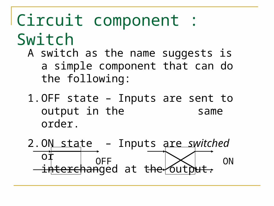
Circuit component : Switch
A switch as the name suggests is a simple component that can do the following:
1. OFF state – Inputs are sent to output in the same order.
2. ON state – Inputs are switched or interchanged at the output.
OFF ON
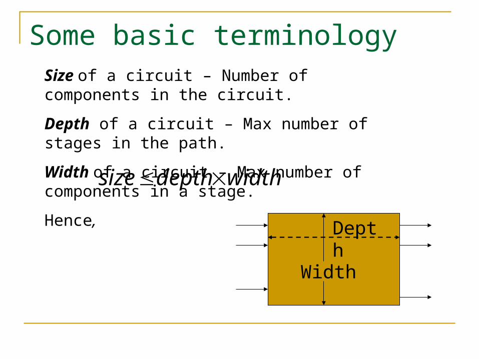
Some basic terminologySize of a circuit – Number of components in the circuit.
Depth of a circuit – Max number of stages in the path.
Width of a circuit – Max number of components in a stage.
Hence,
Width
Depth
widthdepthsize
Lower Bounds
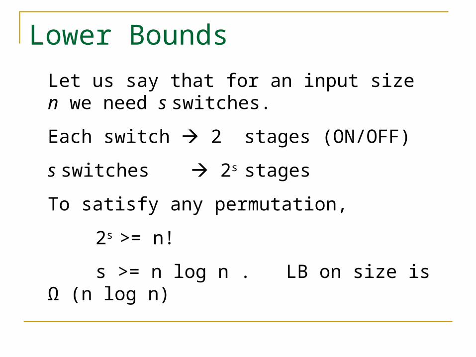
Let us say that for an input size n we need s switches.
Each switch 2 stages (ON/OFF)
s switches 2s stages
To satisfy any permutation,
2s >= n!
s >= n log n . LB on size is Ω (n log n)
Lower Bounds
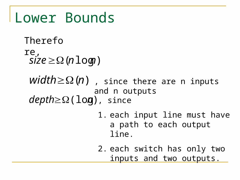
)log( nnsize
)(nwidth
Therefore,
)(log ndepth
, since there are n inputs and n outputs
, since
1. each input line must have a path to each output line.
2. each switch has only two inputs and two outputs.
Permutation Vs. Sorting
The order in which the inputs to a Sorting Circuit appear at the output, depends on the values of the input.
Hence, by having inputs in the form of a pair (i, j) (which implies input i is sent to output j ) we can perform permutations by using a sorting circuit and sorting by the j values.
Permutation Vs. Sorting
Sorting circuits are self-routing. That is, each comparator makes its decision as to which way the data it receives are to be directed; this decision is made when they reach the comparator and is based on their values.
In permutation circuits, switches are to be set ahead of time.
Circuit Design
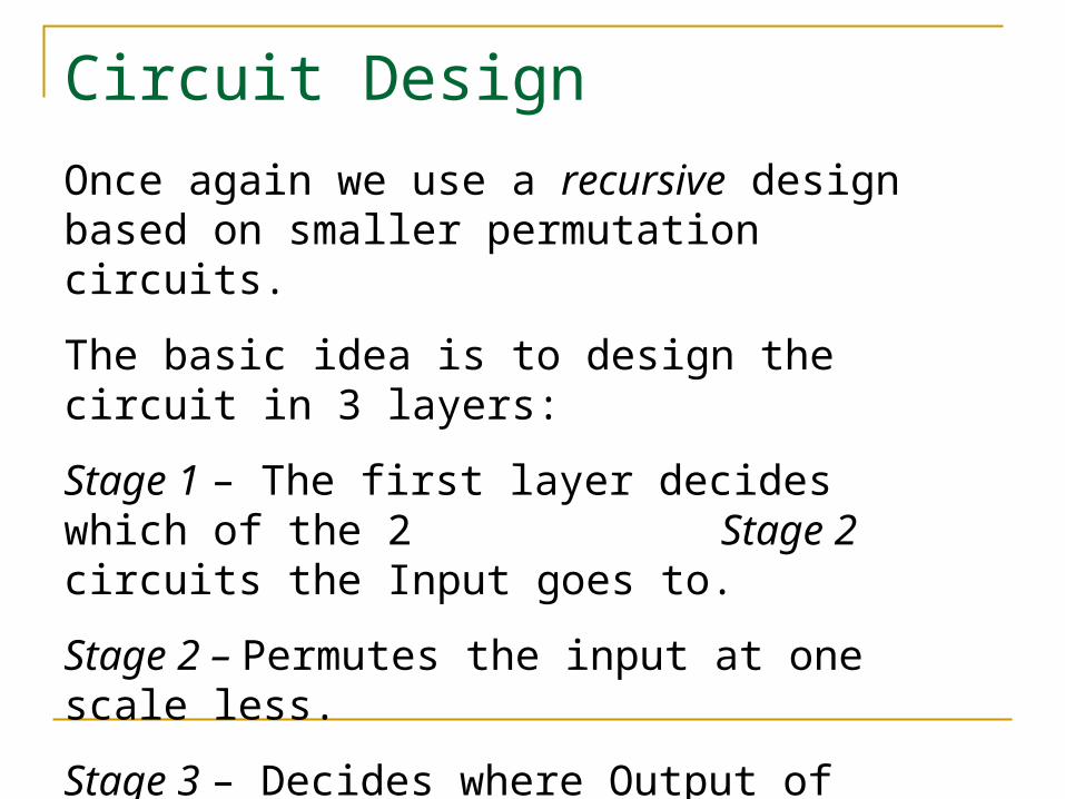
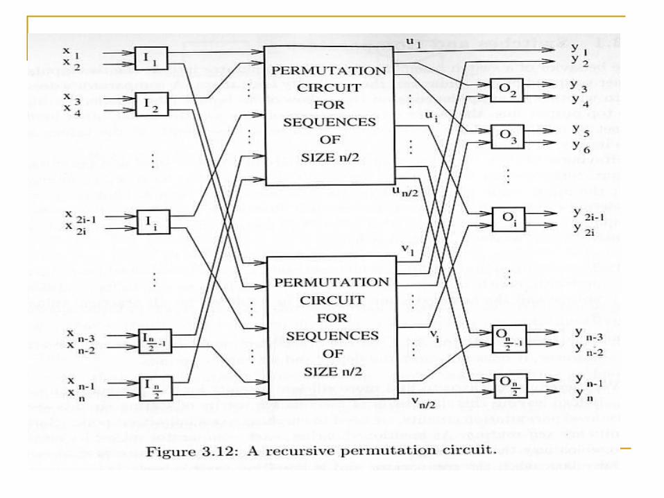
Once again we use a recursive design based on smaller permutation circuits.
The basic idea is to design the circuit in 3 layers:
Stage 1 – The first layer decides which of the 2 Stage 2 circuits the Input goes to.
Stage 2 – Permutes the input at one scale less.
Stage 3 – Decides where Output of Stage 2 goes in the final output sequence.
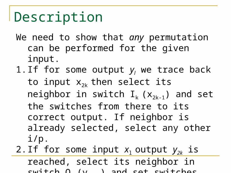
DescriptionWe need to show that any permutation can be
performed for the given input.1. If for some output yl we trace back to input x2k then
select its neighbor in switch Ik (x2k-1) and set the switches from there to its correct output. If neighbor is already selected, select any other i/p.
2. If for some input xl output y2k is reached, select its neighbor in switch Ok (y2k-1) and set switches from there to correct input.
Ping – Pong Technique
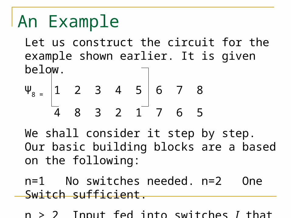
An ExampleLet us construct the circuit for the example shown earlier. It is given below.
Ψ8 = 1 2 3 4 5 6 7 8
4 8 3 2 1 7 6 5
We shall consider it step by step. Our basic building blocks are a based on the following:
n=1 No switches needed. n=2 One Switch sufficient.
n > 2 Input fed into switches I that direct them towards two n/2 permutation circuits.
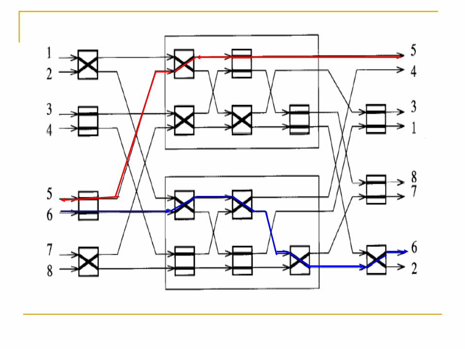
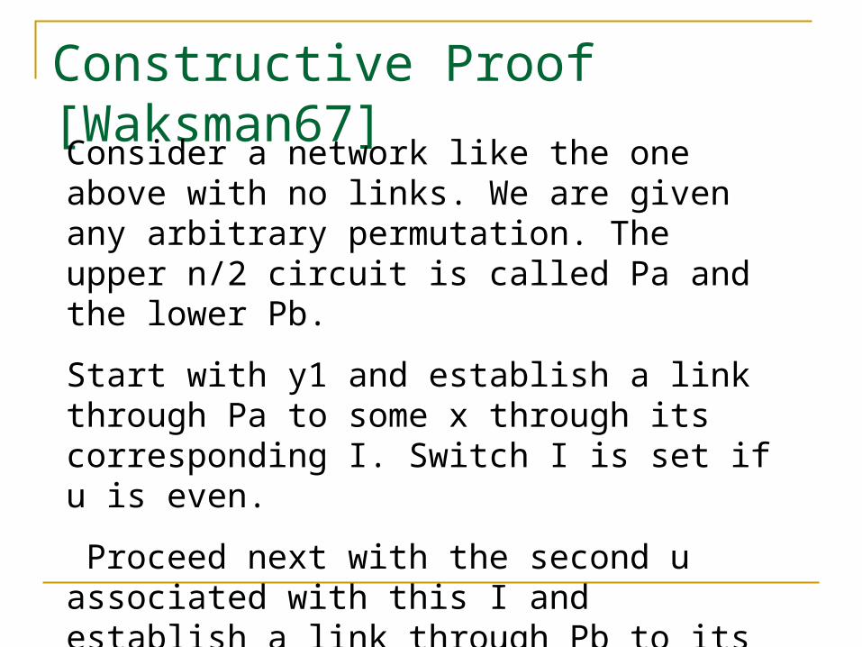
Constructive Proof [Waksman67] Consider a network like the one above with no links. We are given any arbitrary permutation. The upper n/2 circuit is called Pa and the lower Pb.
Start with y1 and establish a link through Pa to some x through its corresponding I. Switch I is set if u is even.
Proceed next with the second u associated with this I and establish a link through Pb to its y through the O associated with it. Set this O if y is even.
Repeat the process until all input-output pairs have been matched.
Now, since by construction Pa and Pb, are each associated with exactly N/2 inputs and N/2 outputs, and since by assumption Pa and Pb are permutation networks the assignment is complete and the link pattern is as in the figure.
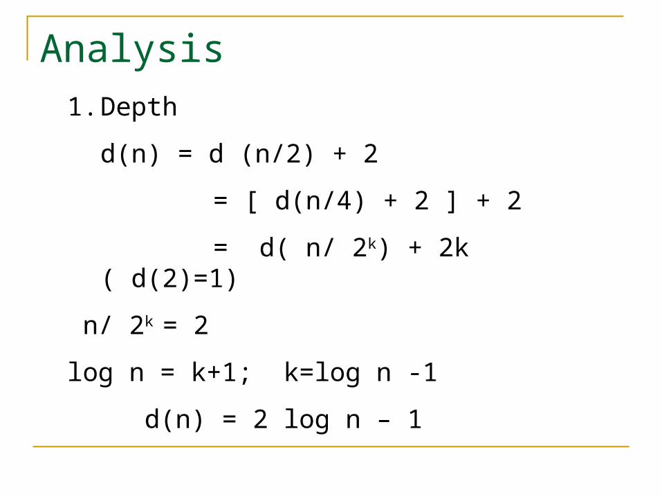
Analysis1. Depth
d(n) = d (n/2) + 2
= [ d(n/4) + 2 ] + 2
= d( n/ 2k) + 2k ( d(2)=1)
n/ 2k = 2
log n = k+1; k=log n -1
d(n) = 2 log n – 1
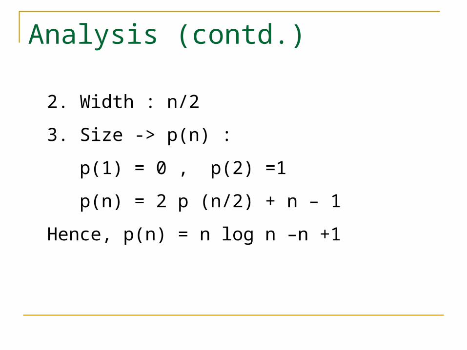
Analysis (contd.)
2. Width : n/2
3. Size -> p(n) :
p(1) = 0 , p(2) =1
p(n) = 2 p (n/2) + n – 1
Hence, p(n) = n log n –n +1
Applications
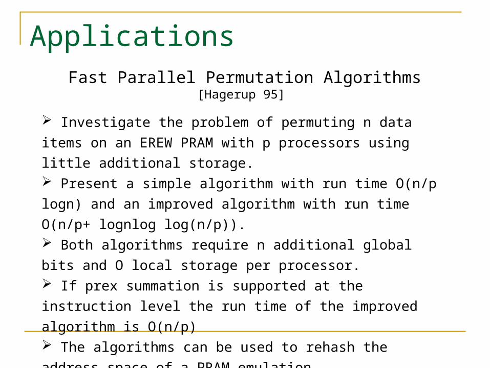
Investigate the problem of permuting n data items on an EREW
PRAM with p processors using little additional storage. Present a simple algorithm with run time O(n/p logn) and an
improved algorithm with run time O(n/p+ lognlog log(n/p)). Both algorithms require n additional global bits and O local storage
per processor. If prex summation is supported at the instruction level the run time of
the improved algorithm is O(n/p) The algorithms can be used to rehash the address space of a PRAM
emulation
Fast Parallel Permutation Algorithms [Hagerup 95]
Applications
Permute along the cycle until you reach it again.
Mark all positions that visited.
Continue until all positions have been visited.
O(n) to move all items and O(n) t search for unvisited
positions.
Sequential Algorithm
Applications
EREW PRAM with p processors.
Each processor P takes care of one block of B=n/p
positions.
P starts with x in its block and follows the cycle until it
meets a position y that is already marked as visited.
P is one of three states: searching, working on a cycle,
terminated.
Time: O((n/p)logn)
Basic Algorithm
Applications
Basic algorithm is not optimal because many processors
could terminate early- unbalanced.
The array of items is dynamically partitioned into active
and passive blocks.
passive: all positions have been visited.
active: split into smaller ones as the algorithm proceeds.
Time: O(n/p + logn log log (n/p))
Improved Algorithm
References
[Akl97] Selim G Akl, Parallel Computation, Prentice Hall, New Jersey, 1997.
[Waksman68] A permutation network. Journal of the ACM, Vol. 15, 1968, pp. 159-163.
[Hagerup 95] Fast Parallel Permutation Algorithms, Journal of Parallel Processing Letters, Vol. 5, No. 2, 995, pp. 139-148.