Embed Size (px)
Citation preview
MagnetanzeigerMagnetic Level Gauges
710
PHÖNiXPHÖNIX MESSTECHNIK GmbH
PHÖNIX MESSTECHNIK GmbHSalzschlirfer Straße 13, D-60386 FrankfurtTel. +49/69/41 67 42 -20Fax -29+49/69/41 67 42
MAGNETANZEIGER
PN 10 - PN 400MAGNETIC LEVEL GAUGES
Rev. 5 07/08PHÖNiX
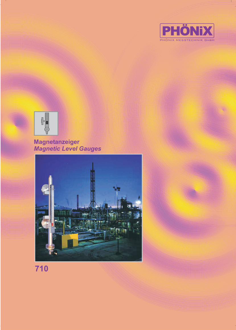
Typ-Übersicht / Types Overview
710.100.0 - 160.0PN40 - 400
710.102.0PN10
710.200.0PN40 - 400
710.100.3 - 160.3PN40 - 400
710.098.0 - 140.0PN40
710.220.0 - 221.0PN16
710.222.0 - 223.0PN16
710.101.0 - 161.0PN40 - 400
710.098.3 - 140.3PN40
710.300.0 - 100.3PN40 - 400
710.101.3 - 161.3PN40 - 400
710.103.0 - 106.0PN40
710.320.0 - 321.0PN16
710.322.0 - 323.0PN16
PHÖNIX MESSTECHNIK GmbHSalzschlirfer Straße 13, D-60386 FrankfurtTel. +49/69/41 67 42 -20Fax -29+49/69/41 67 42
MAGNETANZEIGER
PN 10 - PN 400MAGNETIC LEVEL GAUGES
Rev. 0 08/03PHÖNiX
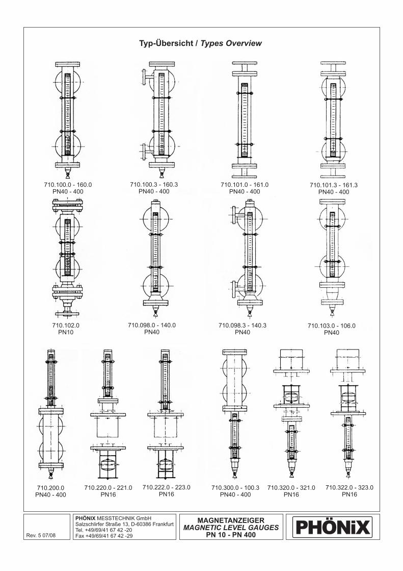
Magnetgesteuerte Niveauanzeiger
- Für alle Flüssigkeiten, besonders geeignet für giftige, korrosive,leicht brennbare, leicht flüchtige und teure Medien
- bis Druckstufe PN 400- geschlossene Schwimmer bis 400 bar Betriebsdruck- Temperaturen von - 200 °C bis + 400 °C (Höhere Drücke undTemperaturen - auf Anfrage)
- Bypassrohr und Schwimmer1.4571 oder Titan
- Abschluß- und Anschlußflansche aus- Anzeige mit zweifarbigen permanentmagnetischen Plättchen
- Andere Werkstoffe nach DIN und ANSI, Sonderlegierungen,verschiedene Kunststoffen sowie Beschichtung und Auskleidung
- Schwimmerfür sehr niedrige spezifische
Gewichte aus Titan- Anzeige für niedrige Temperaturen und/oder korrosiveUmgebung vakuumdicht im Glasrohr eingeschmolzen
- Isoliervorbereitung- Anzeige in Sonderfarben z. B. schwarz/gelb- Graduierte Skalen- Anstriche
- Größte Sicherheit, da Medium von Anzeigevorrichtung getrennt-- Betrieb ohne Hilfsenergie- Schaulänge unbegrenzt, ab 5 m geteilte Ausführung-
- Weithin sehr gut slchtbare kontrastreiche Anzeige
- Extrem niedriger Wartungsaufwand- Jede gewünschte Anschlußart möglich- Anzeige von Trennschichten- Automatisierung durch Anbringen von Grenzkontakten (sieheProduktgruppe 740) auch in Namur-Sicherheitstechnik undFernanzeigen ( mit Reed- undmagnetostriktivem Sensor (auch Ex-geschützt), 4-20 mA, HART,Profibus, Fieldbus
Zone 0, incl. Titan- Germanischer Lloyd
Werks- und Prüfzeugnisse nach EN 10204, Abnahme- undDruckprüfungen, Sauergas und nach Kundenspezifikationen
Bitte verlangen Sie ausführliche Unterlagen oder eine Beratungdurch unsere Spezialisten.
Anwendungsbereiche
WerkstoffeStandardausführung:
Spezialausführungen:
Besondere Vorteile:
Zulassungen:
Zeugnisse:
-
- 4 9 ATEX ,
Allgemeines
Richtlinie 97/23/EG (DGRL)- HPO/DIN EN 729-2/ (ersetzt durch DGRL)
Richtlinie 9 / /EG ( )
aus Edelstahl 1.4571
Edelstahl 1.4571
aus Sonderlegierungen (Hastelloy, Monel..), Glas,Kunststoff, mit Beschichtung und
Messgenauigkeit ±10mm
Spaltfreie Konstruktion- Ausgehalste seitliche Anschlüsse bis 3,5 mm Wandstärke- Magnetsystem rotationssymmetrisch
bis 400 °C- Vibrationsfest durch Anschlag für Anzeigeplättchen- Schwimmer-Kontrolle in der Anzeige- Anzeigeposition über 270° einstellbar- Sichere Anzeige auch mit Doppelrohrheizmantel
siehe Produktgruppe 745)
TRD 201
Magnetically operated Liquid Level Gauges
General
Rating
Materials of constructionStandard type:
Special designs:
Design advantages:
Approvals
Certificates:
- For all liquids, preferential for toxic, corrosive,inflammable, volatile and expensive media
- Pressure range up to PN 400- closed floats up to 400 bar operating pressure- Operating temperature from - 200 °C up to +400 °C (Higher ratingson request)
- Bypass tube float 1.4571 or Titanium- Connecting-, top- and bottom-flanges- Indicator with bi-coloured permanent magnetic wafers
- Other materials according to DIN and ANSI, special alloys, syntheticmaterials, coatings and linings
- Floats made offor very low specific gravities Titanium
- Indicator for low temperature and/or corrosive environment sealedin a glass tube.
- Insulation preparations- Indicator in other colors e. g. black/yellow- Graduated scales- Paintings
- Enhanced safety due to separation between media and indicator-
- Unlimited visible length from 5 m on in split version-
- very good vlslblllty even from far away with c indicatorup to 400 °C
- Vibration resistant due to stopper for indicating elements-
- Extreme low maintenance costs- Each kind of connections possible- Indicating of interface levels- Additional function for measuring and regulating with external limitswitches (see product group 740) also in Namur-safety design andremote sensors of Reed ormagnestostrictive type (also Ex-proof design),
- Directive 97/23/EG (PED)- HPO/DIN EN 729-2/ (replaced by PED)- Directive 94/9/EG (ATEX), Zone 0, incl. Titanium- Shipbuilding German Lloyd
Works and test certificates acc. to EN 10204, inspections andpressure tests, sour gas and acc. to customer's specifications
Please ask for our detailed literature or the advice of our engineers.
stainless steel 1.4571,stainless steel 1.4571
special alloys (Hastelloy, Monel...), glass, syntheticmaterials, with coating and
Measuring precision ±10mm- Operation without power supply
Gap-free construction- Sideways connection extruded up to 3.5 mm wall thickness- Magnet system rotational symmetric
ontrast-rich
Float-control in the level display- Display position over 270° adjustable- Safe display also with double pipe heating
(see product group 745)4-20 mA, HART,
Profibus, Fieldbus
TRD 201
PHÖNIX MESSTECHNIK GmbHSalzschlirfer Straße 13, D-60386 FrankfurtTel. +49/69/41 67 42 -20Fax -29+49/69/41 67 42
MAGNETANZEIGER
PN 10 - PN 400MAGNETIC LEVEL GAUGES
Rev. 0 08/03
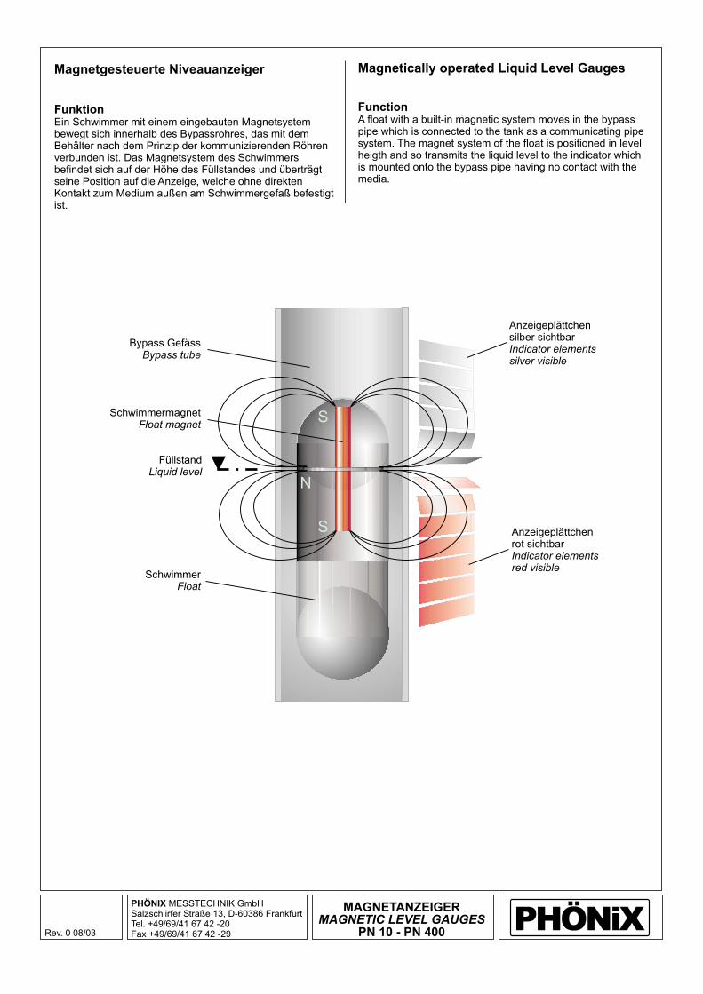
Anzeigeplättchensilber sichtbarIndicator elementssilver visible
Anzeigeplättchenrot sichtbarIndicator elementsred visible
SchwimmermagnetFloat magnet
FüllstandLiquid level
SchwimmerFloat
Bypass GefässBypass tube
PHÖNiX
Magnetgesteuerte Niveauanzeiger
FunktionEin Schwimmer mit einem eingebauten Magnetsystembewegt sich innerhalb des Bypassrohres, das mit demBehälter nach dem Prinzipverbunden ist. Das Magnetsystem des Schwimmersbefindet sich auf der Höhe des Füllstandes und überträgtseine Position auf die Anzeige, welche ohne direktenKontakt zum Medium außen am Schwimmergefaß befestigtist.
der kommunizierenden Röhren
Magnetically operated Liquid Level Gauges
FunctionA float with a built-in magnetic system moves in the bypasspipe which is connected to the tank as a communicating pipesystem. The magnet system of the float is positioned in levelheigth and so transmits the liquid level to the indicator whichis mounted onto the bypass pipe having no contact with themedia.
S
S
N

PHÖNIX MESSTECHNIK GmbHSalzschlirfer Straße 13, D-60386 FrankfurtTel. +49/69/41 67 42 -20Fax -29+49/69/41 67 42
MAGNETANZEIGER
PN 10 - PN 400MAGNETIC LEVEL GAUGES
Rev. 0 08/03
Magnetgesteuerte Niveauanzeiger
AnzeigeleisteDie permanentmagnetischen Anzeigeplättchen der PHÖNIXAnzeigevorrichtung sind drehbar gelagert, so daß sie sichan den Feldlinien des Magnetsystems ausrichten. Da dieRichtung der Feldlinien von der Mitte des Magnetsystemsaus entgegengesetzt verläuft, zeigen die Plättchen oberhalbund unterhalb des Füllstandes die entgegengesetzte Farbe,z. B. rot und silber. Die Plättchen sind auskorrosionsbeständigem Edelstahl.
Die Wahl der Anzeigevorrichtung hängt u. a. von denBetriebsbedingungen ab. Für normale Betriebsbedingungenund Mediumstemperaturen von -10 bis +400 °C besitzt dieAnzeigeleiste ein Aluminiumgehäuse mit Glasabdeckung.Für tiefe Temperaturen oder stark korrosive Umgebungbefindet sich die Anzeige in einem Glasrohr, das hermetischdicht ist.
Die Anzeigevorrichtung kann für jeden gewünschtenSichtwinkel innerhalb von 270° montiert werden, da dasMagnetsystem rotationssymmetrisch ist, eineSchwimmerausrichtung ist daher nicht notwendig. Dievertikale Position ist durch einen Auflagering am Anzeigerfestgelegt.
Die PHÖNIX Anzeige verfügt über eineSchwimmerkontrolle. Diese besteht aus dreiAnzeigeelementen am unteren Ende die mit umgekehrterMagnetisierung eingesetzt sind. Befindet sich dasMagnetsystems des Schwimmers oberhalb des unterenStutzens, zeigt die Schwimmerkontrolle silber, sinkt derSchwimmer darunter wechselt die Anzeige zu rot und zeigtdamit einen Schwimmerdefekt oder ein leeres Gefäss an.
Magnetically operated Liquid Level Gauges
IndicatorThe permanent magnetic indicating elements of the PHÖNIXindicator are carried rotatable so that they can align along themagnetic field lines of the float magnet. As the direction of thefield lines is changing in the center of the magnetic systemthe indicating elements show different colors above andbelow the liquid level, i. e. red and silver. The material of the
elements is corrosion resistant SS.
The indicator is chosen according to the operation conditions.For normal operating conditions and media temperature from-10 to +400 °C the indicator housing is made of aluminiumwith a glass cover. For low temperature or highly corrosiveenvironment the indicator is hermetically sealed in a glasstube.
The indicator can be mounted for any sight direction within anangle of 270° as the magnet system is rotationallysymmetrical, i. e. that the float has not be directed. Thevertical position is fixed with a support at the gauge tube.
The PHÖNIX indicator is equipped with a float control. Thisconsists of three indicating elements inserted at the lower endin opposite direction of magnetisation. When the float isabove the lower connection the float control shows silver,when the float is below the float control changes to red. Thisindicates a float defect or an empty gauge tube.
indicating
Schwimmermagnetfloat magnet
Schwimmerkontrolle aktivfloat control active
Anzeigeplättchenindicating elements
N
S
S
PHÖNIX MESSTECHNIK GmbHSalzschlirfer Straße 13, D-60386 FrankfurtTel. +49/69/41 67 42 -20Fax -29+49/69/41 67 42
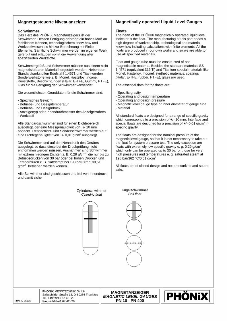
ZylinderschwimmerCylindric float
KugelschwimmerBall float
MAGNETANZEIGER
PN 10 - PN 400MAGNETIC LEVEL GAUGES
Rev. 0 08/03
Magnetgesteuerte Niveauanzeiger
SchwimmerDas Herz des PHÖNIX Magnetanzeigers ist derSchwimmer. Dessen Fertigung erfordert ein hohes Maß anfachlichem Können, technologischem know-how undWerkstoffwissen bis hin zur Berechnung mit FiniteElemente. Sämtliche Schwimmer werden im eigenen Werkgefertigt und erlauben somit die Verwendung allerspezifizierten Werkstoffe.
Schwimmergefäß und Schwimmer müssen aus einem nichtmagnetisierbaren Material hergestellt werden. Neben denStandardwerkstoffen Edelstahl 1.4571 und Titan werdenSonderwerkstoffe wie z. B. Monel, Hastelloy, Inconel,Kunststoffe, Beschichtungen (Halar, E-TFE, Gummi, PTFE),Glas für die Fertigung der Schwimmer verwendet.
Die wesentlichsten Grunddaten für die Schwimmer sind:
- Spezifisches Gewicht- Betriebs- und Designtemperatur- Betriebs druck- Anzeigertyp oder Innendurchmesser des Anzeigerrohres- Werkstoff
Alle Standardschwimmer sind für einen Dichtebereichausgelegt, der eine Messgenauigkeit von +/- 10 mmabdeckt. Trennschicht- und Sonderschwimmer werden aufeine Dichtegenauigkeit von +/- 0,01
Die Schwimmer sind auf den Nenndruck des Gerätesausgelegt, so dass diese bei der Druckprüfung nichtentnommen werden müssen. Ausnahmen sind Schwimmermit extrem niedrigen Dichten z. B. 0,29 g/cm die nur bis zuBetriebsdrücken von 30 bar oder bei hohen Drücken undTemperaturen z. B. Sattdampf bei 198 bar/362 °C/0,51g/cm betrieben werden können.
3
- und Design
g/cm ausgelegt.
Alle Schwimmer sind geschlossen und frei von Innendruckund damit sicher.
3
3
Magnetically operated Liquid Level Gauges
FloatsThe heart of the PHÖNIX magnetically operated liquid levelindicator is the float. The manufacturing of this part needs ahigh degree of workmanship, technological and materialknow-how including calculations with finite elements. All thefloats are produced in our own works and so we are able touse all specified materials.
Float and gauge tube must be constructed of nonmagnetisable material. Besides the standard materials SS1.4571 (equivalent 316 Ti) and Titanium special materials likeMonel, Hastelloy, Inconel, synthetic materials, coatings(
The essential data for the floats are:
- Specific gravity- Operating and design temperature- Operating pressure- Magnetic level gauge type or inner diameter of gauge tube- Material
All standard floats are designed for a range of specific gravitywhich corresponds to a precision of +/- 10 mm. Interface andspecial floats are designed for a precision of +/- 0,01 in
The floats are designed for the nominal pressure of themagnetic level gauge, so that it is not neccessary to take outthe float for system pressure test. The only exception arefloats with extremely low specific gravity e. g.which only can be operated up to 30 bar or those for veryhigh pressures and temperatures e. g. saturated steam at
Halar, E-TFE, rubber, PTFE), glass are used.
and design
g/cmspecific gravity.
0,29 g/cm
198 bar/362 °C/0,51 g/cm
All floats are of closed design and not pressurized and so aresafe.
3
3
3.
PHÖNIX MESSTECHNIK GmbHSalzschlirfer Straße 13, D-60386 FrankfurtTel. +49/69/41 67 42 -20Fax -29+49/69/41 67 42
MAGNETANZEIGER
PN 10 - PN 400MAGNETIC LEVEL GAUGES
Rev. 0 08/03
Magnetgesteuerte Niveauanzeiger
ZubehörKontakte
Fernanzeige
Absperrventile
Ablaß-/Entlüftungs-Einrichtungen
Sämtliche PHÖNIX Magnetanzeiger können mit einem odermehreren PHÖNIX Kontakten ausgerüstet werden.Detaillierte Informationen finden Sie in den zugehörigenDatenblättern Produktgruppe 740.Sie können diese einsetzen z. B. als Hoch- bzw.Tiefalarmschalter, für Pumpensteuerungen oder alsSignalgeber für Füll- bzw. Entleerschaltungen.
Alle PHÖNIX Magnetanzeiger können mit elektronischenFernanzeigevorrichtungen ausgerüstet werden.
PHÖNIX empfiehlt den Einbau von Absperrventilen mög-lichst mit Regulierkegel zwischen Behälter und Anzeiger, umbei der Anfahrphase der Anlage ein Beschädigen derSchwimmer durch Druckstöße zu vermeiden.
Alle PHÖNIX können entweder mit Ablaß.bzw. Entlüflungsventilen, Flanschen oderVerschlussschrauben bzw. gemäss den Anforderungen desKunden ausgerüstet werden.
Änderungen vorbehalten.
DetaillierteInformationen finden Sie in den zugehörigen DatenblätternProduktgruppe 745.
Magnetanzeiger
Magnetically operated Liquid Level Gauges
AccessoriesSwltches
Remote Control
Isolating valves
Drain/Vent devices
All PHÖNIX magnetically operated liquid level gauges can beequipped with one ore more PHÖNIX switches. Detailedinformations please find in the datasheets product group 740.The switches can be used e. g. for high or low level alarms,pump switching and for fill or drain operations.
All PHÖNIX magnetically operated liquid level gauges can beequipped with PHÖNIX sensors to get an analogue signal.
PHÖNIX recommends the mounting of isolating valves(possibly with regulating plug) between tank and level gaugesin order to avoid a damage of the floats during the startup-upprocedure.
PHÖNIX magnetically operated liquid level gauges can beequipped either with drain and/or vent valves, flanges orplugs rsp. acc. to customer's requirements.
Subject to alterations.
Detailed informations please find in the datasheets productgroup 745.

PHÖNIX MESSTECHNIK GmbHSalzschlirfer Straße 13, D-60386 FrankfurtTel. +49/69/41 67 42 -20Fax -29+49/69/41 67 42
MAGNETIC LEVEL GAUGESPN 10 - PN 400
Rev. 1 09/03PHÖNiX
Magnetically operated Liquid Level Gauges
Type data overview
Required data:
Float design
Note
- P (Design- and process pressure)- T (Design- and process temperature)- sg (specific gravity, lower, upper)- Connection to containment, tank- Vent/drain type- Material- Measuring lengthLevel, interface
- Closed floatsup to 400 bar max Pproce. g. 362 °C T at 198 bar P saturated steam
(sg=0,51 g/cm ).
- 710...0no heating jacket
- 710...3with heating jacket
Subject to alterations.
op op3
Other densities and materials on request710.102.0: float material=material of tube
710.102.0710.102.0710.102.0710.102.0710.103.0710.098.0/.098.3710.104.0/.104.3
710.106.0710.110.0/.110.3710.120.0/.120.3710.130.0710.140.0710.150.0710.160.0710.200/.300.0710.220/.320.0710.221/.321.0710.222/.322.0710.222.5710.223/.323.0
710.100.0/.101.3
PVCPEPPPVDF
/PTFE
/Gummi
SSSSSSSSSSSSSSSSSSSSSSSSSSSSSSSSSS
Type Material
Float for sg[g/cm ]
3
1.4571 Titanium
atT [°C]
Tmax[°C]
standardIndication tube /
bypass tube
DesignPressure
P[bar]
1025
616101952
2552
103160250320400
52/103
52
400400400400400
63,0 x63,0 x63,0 x60,3,0 x 2,9
76,1 x 2,9/
76,1 x 5,080,0 x 8,588,9 x 11,088,0 x 15,076,1 x 2,9
57,0
63,0 x 3,03,03,03,0
42,4 x 2,0 / 57,0 x 2,942,4 x 2,0 / 57,0 x 2,957,0 x 2,9 / 76,9 x 2,960,3,0 x 2,9
/ 88,9 x 3,276,1 x 4,0 88,9 x 3,2
x 2,957,0 x 2,957,0 x 2,957,0 x 2,957,0 x 2,9
+20...+60+20...+40+20...+50
-10...+140-10...+140
-200...+400-200...+400-200...+400
-10...+80-200...+400-200...+400-200...+400-200...+400-200...+400-200...+400-200...+400-200...+400-200...+400-200...+400-200...+400-200...+400
+60+40+90
+140+140+400+400+400
+80+400+400+400+400+400+400+400+400+400+400+400+400
0,70...2,000,70...2,000,70...2,000,70...2,000,70...2,000,70...1,670,74...1,60,75...1,5270,64...2,00
Custom designCustom designCustom designCustom designCustom design
0,54...0,780,48...1,430,64...2,000,29...0,720,57...1,170,57...1,170,51...1,270,51...1,030,51...1,030,51...1,17

400
Ppro
c[b
ar]
Tproc [°C]
350
300
250
200
150
100
50
00 50 100 150 200 250 300 350 400-50-100-150-200
400
Ppro
c[b
ar]
Tproc [°C]
350
710.160
710.160
710.150
710.150
710.140
710.140
710.130
710.130
710.120
710.120
710.100/104/110
710.100/104/110
710.098
710.098
710.106
710.106
710.103
710.103
300
250
200
150
100
50
00 50 100 150 200 250 300 350 400-50-100-150-200
Magnetgesteuerte Niveauanzeiger
P - T - Diagramm
P - T - Diagramm
Werkstoff: 1.0460
Werkstoff: 1.4571
Änderungen vorbehalten.
Magnetically operated Liquid Level Gauges
P - T - Diagram
P - T - Diagram
Material: 1.0460
Material: 1.4571
Subject to alterations.
PHÖNIX MESSTECHNIK GmbHSalzschlirfer Straße 13, D-60386 FrankfurtTel. +49/69/41 67 42 -20Fax -29+49/69/41 67 42
MAGNETANZEIGER
PN 10 - PN 400MAGNETIC LEVEL GAUGES
Rev. 0 08/03PHÖNiX
PHÖNIX MESSTECHNIK GmbHSalzschlirfer Straße 13, D-60386 FrankfurtTel. +49/69/41 67 42 -20Fax -29+49/69/41 67 42
MAGNETANZEIGER
PN 10 - PN 400MAGNETIC LEVEL GAUGES
Rev. 2 11/07PHÖNiX
Magnetically operated Liquid Level Gauges
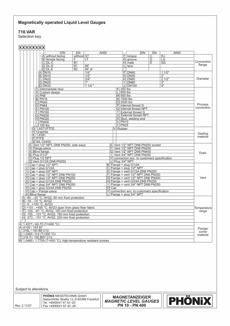
710.VARSelection key
Subject to alterations
X
A
6
1
E
B
G V
A
4
A
0
F
K
F
F
without facing without C
Vent 1/2" NPT, DN8 PN250, side ways
Cap + plug 1/2" NPT
Vent socket1/2" NPT DN8 PN250
Flange + plug G1/2A
1.4571/PTFE Rubber
-60...-20 °C, AVG2, 60 mm frost protection
1.4571 / A2-70 (T<400 °C)
DN10
Intermediate stud
PN160
300 lbs
tongue
DN40
ST
1/4"
RJ
1 1/2"
female facing F D
Flange-piece
Cap + plug G1/2A
Vent 1/2" NPT DN8 PN250
Flange + plug 1/2" NPT
Graphite
-19...-10 °C, AVG2
A105 / 193 B7
DN15
PN250
Custom design 600 lbs
Stud, welding end
groove
DN50
LT
1/2"3/4"
LG
2"
DL-C B1 E
Blind flange
Cap + plug 3/4" NPT
Vent 1/2" NPT DN6 PN400
Flange + vent G1/2A DN8 PN250
1.4391
-9...+150 °C, AVG3
316L / 193 B8 C12
-100...-61 °C, AVG2, 100 mm frost protection
1.0460 / 1.7709 (T<400 °C), high-temperature resistant screws
DN20
PN320
External thread G
PN6 900 lbs
male
DN65
SG
2 1/2"3"4"
DL-D B1
Plug G1/2"
Cap + plug 1/2" NPT DN6 PN100
Cap + plug 3/4" NPT DN8 PN250
Vent 3/4" NPT DN8 PN250
Flange + vent 1/2" NPT DN8 PN250
Flange + vent 3/4" NPT DN8 PN250
PTFE
+151...+450 °C, AVG3 span from glass fiber fabric
1.0460 / 8.8 (T<300 °C)
-150...-101 °C, AVG2, 150 mm frost protection
DN25
PN400
External thread NPT
PN16 1500 lbs
PN64 Internal thread GInternal thread NPT
PN25
lens
DN80DN100
RF
1"
DL-E B2
Plug 1/2 NPT
Cap + plug 1/2" NPT DN8 PN250
Cap + plug G3/4A DN8 PN250
connection acc. to customers specificationPlug 3/4" NPT
Flange + vent 1/2" NPT DN6 PN400Flange + vent G3/4A DN8 PN250
connection acc. to customers specificationFlange + plug 3/4" NPT
Cap
Vent G1/2A DN8 PN250
Cap + plug G1/2A DN8 PN250
Cap + Flange-pieceBlind flange
SIL C4400
316 Ti / 193 B8T C12
-273...-151 °C, AVG2, 200 mm frost protection
DN32
150 lbs
PN40 2500 lbs
PN10
PN100
RF sf
1 1/4 "
B
9
2
F
C
H
B
A
B
G
9 L
X
G
G
C
A
3
G
D
K
C
L
F
W
C
H
T
A M
H
H
D
B
4
7
I
F
I
P
D
S
G
D
I
U
B N
L
IJ
E
C
5
8
Yc
GH
OYc
D
6
9A
S
T
H
E
J
C O
b
D PQ
c
E
DIN EN ENDINANSI ANSI
Connectionflange
Diameter
Processconnection
Sealingmaterial
Temperaturerange
Flange/screw
material
Drain
Vent
X X X X X X X
Heatingsee710.HEAT
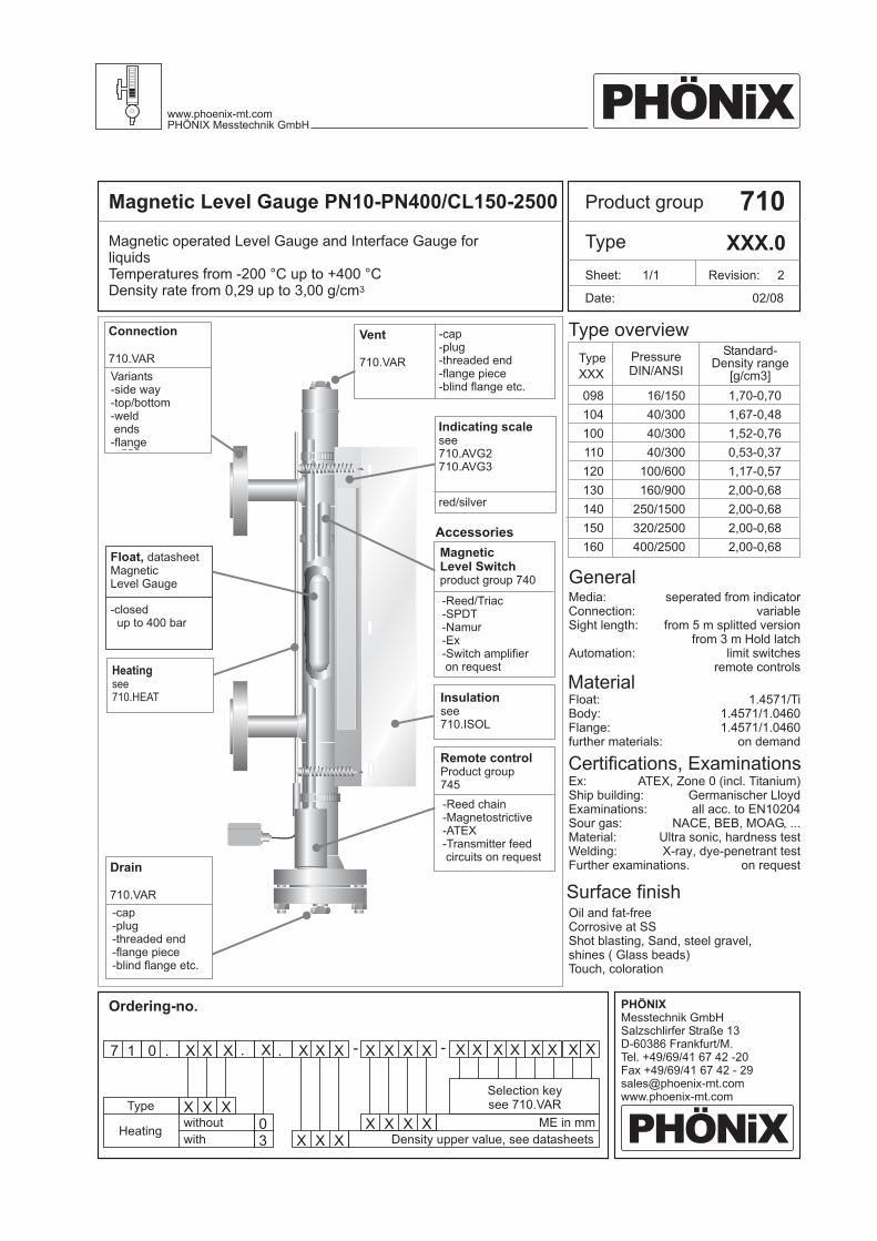
Product groupMagnetic Level Gauge PN10-PN400/CL150-2500 710
Type XXX.0Magnetic operated Level Gauge and Interface Gauge forliquidsTemperatures from -200 °C up to +400 °CDensity rate from 0,29 up to 3,00 g/cm3
Ordering-no.
General
Date:
Revision: 2
02/08
098
104
100
110
120
130
140
150
160
Type
XXX
Standard-Density range
[g/cm3]
16/150
40/300
40/300
40/300
100/600
160/900
250/1500
320/2500
400/2500
1,70-0,70
1,67-0,48
1,52-0,76
0,53-0,37
1,17-0,57
2,00-0,68
2,00-0,68
2,00-0,68
2,00-0,68
Vent
710.VAR
-cap-plug-threaded end-flange piece-blind flange etc.
Drain
710.VAR
-cap-plug-threaded end-flange piece-blind flange etc.
Remote controlProduct group745
-Reed chain-Magnetostrictive-ATEX-Transmitter feedcircuits on request
MagneticLevel Switchproduct group 740
-Reed/Triac-SPDT-Namur-Ex-Switch amplifieron request
Insulationsee710.ISOL
Type overview
Indicating scalesee710.AVG2710.AVG3
Sheet: 1/1
red/silver
Float, datasheetMagneticLevel Gauge
Accessories
-closedup to 400 bar
Connection
710.VAR
Variants-side way-top/bottom-weldends
-flange
PressureDIN/ANSI
Material
Certifications, ExaminationsEx:Ship building:Examinations:Sour gas:Material:Welding:Further examinations.
Surface finishOil and fat-freeCorrosive at SSShot blasting, Sand, steel gravel,shines ( Glass beads)Touch, coloration
Media:Connection:Sight length:
Automation:
Float:Body:Flange:further materials:
seperated from indicatorvariable
from 5 m splitted versionfrom 3 m Hold latch
limit switchesremote controls
1.4571/Ti1.4571/1.04601.4571/1.0460
on demand
ATEX, Zone 0 (incl. Titanium)Germanischer Lloydall acc. to EN10204
NACE, BEB, MOAG, ...Ultra sonic, hardness testX-ray, dye-penetrant test
on requestAcc.
Accessories
PHÖNiXwww.phoenix-mt.comPHÖNIX Messtechnik GmbH
PHÖNiX
PHÖNIXMesstechnik GmbHSalzschlirfer Straße 13D-60386 Frankfurt/M.Tel. +49/69/41 67 42 -20Fax +49/69/41 67 42 - [email protected]
7 1 0 . X
X
XX X
X
XX
X
XX0
3
X X . X
Type
Heatingwithout
with
. X X X X X X X
Density upper value, see datasheets
ME in mm
X X X X X X X X- -
Selection keysee 710.VAR
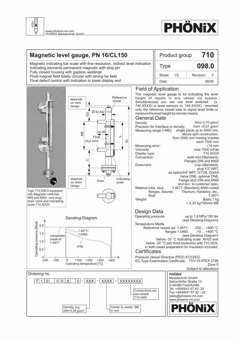
Magnetic level gauge, PN 16/CL150 710
098.0
7 XXXXXXXXXXXXXXX1 0 . 0 9 .8 0 - - -
08/06
10
0 42,4x2
ca.90
ME
C
Revision: 7
Magnetic indicating bar scale with fine resolution, indirect level indicationIndicating elements permanent magnetic with stop pinFully closed housing with gapless weldingsFloat magnet field totally circular with strong far fieldFloat defect control with indication in lower display end
The magnetic level gauge is for indicating the levelheight of liquids in any vessel via bypass.Simultaneously you can use level switches (s.740.XXXX) or level sensors (s. 745.XXXX) mountedonto the reference vessel tube to signal level limits ormeasure the level height by remote means.
Field of Application
Product group
Type
Date:
Sheet: 1/2
General DataDensity:Precision for Interface or density:Measuring range (=ME):
Measuring error:Viscosity:Display type:Connection:
Drain/vent:
Material tube, stud,flanges, fixtures:float:
Weight:
from 0,70 g/cm
single piece up to 5000 mm,above split construction,
from 3000 mm holding bracketeach 1500 mm
10 mmmax 1000 mPas
710.AVG3weld end (Standard),
Cap (Standard),plug 1/2" NPT,
as option3/4" NPT, G1/2A, G3/4AValve DN6, optional DN8,
Flange stud DIN and ANSIand acc. to customer spec.
(Standard),Titanium, Hastelloy, etc.,
1.4571Basic 7 kg
+ 0,33 kg/100mm ME
3
from 0,01 g/cm
Flanges DIN and ANSI
1.4571 ANSI-coded
3±
±
Type 710.098.0 equippedwith Magnetic switchesMIN and MAX, vent plug,drain valve and indicartingscale 710.AVG3.
dependson ventdesign
Referencevessel
Float
stud conn.
dependson draindesign
Indicatingscale
Drain
Operating pressure:
Temperature MediaReference vessel cpl. 1.4571:
flanges 1.0460:
up to 1, MPa/150 lbs(see Derating-Diagram)
- ... +400 °C
9
200-10 ... +400 °C
(see Derating-Diagram)Below -10 °C Indicating scale .AVG2 and
below -20 °C add frost protection with 710.ISOLIn both cases preparation for insulation included.
Design Data
Subject to alterations
Ordering no.
Connections etc.see sheett710.VAR
Density, e.g.054=0,54 g/cm
3
Center to center MEin mm
PHÖNiXwww.phoenix-mt.comPHÖNIX Messtechnik GmbH
PHÖNiX
PHÖNIXMesstechnik GmbHSalzschlirfer Straße 13D-60386 Frankfurt/M.Tel. +49/69/41 67 42 -20Fax +49/69/41 67 42 - [email protected]
TÜV 03 ATEX 2190Zone 0
Pressure Vessel Directive (PED) 97/23/EGEC-Type Examination Certificate:
Certificates
Operating temperature [°C]
0,5
1,0
1,5
2,0
0-100
Derating-Diagram
+100 +200 +300 +400-200 0
completelymade of1.4571
316L
1.4571/1.0460
Op
era
tin
gp
ressu
re[M
pa
]
GL
b

710
098.0
08/06
Operating pressure:
Test pressure:Operating temperature:
to 1, MPa/150 lbs(see derating diagram)
operating pressure x 1,3- ... +400 °C
9
200(see derating diagram)
Design Data
1,21 ... 1,671,03 ... 1,210,90 ... 1,030,81 ... 0,900,75 ... 0,810,70 ... 0,75
Interface float (individually designed g/cm )3
±0.01
139164194224259299
125150180210245285
8797
106117130144
Æ32
Magnetsystem
BG1000984167BG1000984121BG1000984103BG1000984090BG1000984081BG1000984075BG1001044TRX
Float material 1.4571, 32, PN16Æ
Revision: 7
L
45
DetailsFloat, Vent, Drain and Connection
Product group
Type
Date:
Sheet: 2/2
inse
rtio
nd
ep
th
Density range[g/cm ]
3
Measure C[mm]
Total length L[mm]
Weight[g] Part no.
Density range corresponds to measuring error 10 mm±
Vent
Drain
Flangepiece
Valve Valve sidewaysPlug
½ NPT
FlangeWeld end Threadedend
Connections
Subject to alterations
There may be any other customer specified connections, materials and special floats.
DesignationDevice Part no.Product group
FloatIndicating scaleSealingFixing springsAlign magnet
Magnetic switchLevel sensorIndicating scaleFrost protectionHeating
s. Float table aboveBG10.AVGX04750395XXX3813000672BG10XXXXMAKU
740.XXXX745.XXXX710.AVGX710.PLEXI710.HEAT
Accessories: Spare parts:
Ordering no.
CapFlangepiece
ValvePlug
½ NPT
PHÖNiXwww.phoenix-mt.comPHÖNIX Messtechnik GmbH
PHÖNiX
PHÖNIXMesstechnik GmbHSalzschlirfer Straße 13D-60386 Frankfurt/M.Tel. +49/69/41 67 42 -20Fax +49/69/41 67 42 - [email protected]
ca.20
ca.50
ca.90
ca.95 ca.50
ca.75
ca. 75
ca.70
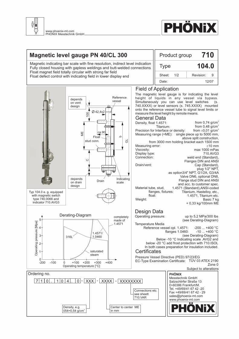
Magnetic level gauge PN 40/CL 300 710
104.0Magnetic indicating bar scale with fine resolution, indirect level indicationFully closed housing with gapless weldings and butt-welded connectionsFloat magnet field totally circular with strong far fieldFloat defect control with indicating field in lower display end
Ordering no.
7 XXXXXXXXXXXXXXX1 0 . 1 0 .4 0 - - -
12/07
Density, float 1.4571:Titanium:
Precision for Interface or density:Measuring range (=ME):
Measuring error:Viscosity:Display type:Connection:
Drain/vent:
Material tube, stud,flanges, fixtures:float:
Weight:
Operating pressure:
Temperature MediaReference vessel cpl. 1.4571:
flanges 1.0460:
from 0,74 g/cmfrom
single piece up to 5000 mm,above split construction,
from 3000 mm holding bracket each 1500 mm10 mm
max 1000 mPas710.AVG3
weld end (Standard),
Cap (Standard),plug 1/2" NPT,
as option3/4" NPT, G1/2A, G3/4AValve DN6, optional DN8,
Flange stud DIN and ANSIand acc. to customer spec.
(Standard),Titanium, Hastelloy, etc.,
1.4571, Titanium etc.Basic 7 kg
+ 0,33 kg/100mm ME
3
0,48 g/cmfrom 0,01 g/cm
Flanges DIN and ANSI
1.4571 ANSI-coded
3
3±
±
up to 5,2 MPa/300 lbs(see Derating-Diagram)
- ... +400 °C200-10 ... +400 °C
(see Derating-Diagram)Below -10 °C Indicating scale .AVG2 and
below -20 °C add frost protection with 710.ISOLIn both cases preparation for insulation included.
General Data
Design Data
The magnetic level gauge is for indicating the levelheight of liquids in any vessel via bypass.Simultaneously you can use level switches (s.740.XXXX) or level sensors (s. 745.XXXX) mountedonto the reference vessel tube to signal level limits ormeasure the level height by remote means.
Connections etc.see sheett710.VAR
Density, e.g.054=0,54 g/cm
3
Center to center MEin mm
Subject to alterations
Typ 104.0 e. g. equippedwith magnetic switchtype 740.0066 andindicator 710.AVG3
Field of Application
Product group
Type
Date:
Sheet: 1/2 Revision: 9
PHÖNiXwww.phoenix-mt.comPHÖNIX Messtechnik GmbH
PHÖNiX
PHÖNIXMesstechnik GmbHSalzschlirfer Straße 13D-60386 Frankfurt/M.Tel. +49/69/41 67 42 -20Fax +49/69/41 67 42 - [email protected]
TÜV 03 ATEX 2190Zone 0
Pressure Vessel Directive (PED) 97/23/EGEC-Type Examination Certificate:
Certificates
10
0 42,4x2
ca.90
ME
C
dependson ventdesign
Referencevessel
Float
stud conn.
dependson draindesign
Indicatingscale
Drain
Operating temperature [°C]
1
2
0-100
Derating-Diagram
+100 +200 +300 +400-200 0
completelymade of1.4571
1.4571/1.0460316L3
4
5
Op
era
tin
gp
ressu
re[M
pa
]
saturatedsteam
GL
b

Details 710
104.0Float, Vent, Drain and Connection
12/07
Operating pressure:
Test pressure:Operating temperature:
There may be any other customer specified connections, materials and special floats.
CapFlangepiece
Flangepiece FlangeWeld end Threaded
end
Valve
Valve Valve sideways
Plug½ NPT
Plug½ NPT
up to 5,2 MPa/300 lbs(see Derating-Diagram for 1.4571)
Operating pressure x 1,3- ... +400 °C200
(see Derating-Diagram for 1.4571)
Design Data
Subject to alterations
Density range[g/cm ]
3
Density range[g/cm ]
3
1,32 ... 1,671,10 ... 1,310,97 ... 1,090,87 ... 0,960,80 ... 0,860,74 ... 0,79
Interface float (individually designed g/cm )3
±0.01
1,09 ... 1,430,89 ... 1,080,75 ... 0,880,66 ... 0,740,60 ... 0,650,55 ... 0,590,51 ... 0,540,48 ... 0,50
Interface float (individually designed g/cm )3
±0.01
139169199239279329
139174214254304364434524
125155185225265315
125160200240290350420510
93106118134149169
778799
109124141162187
Æ32
Æ32
Magnet-system
Magnet-system
BG1001044167BG1001044131BG1001044109BG1001044096BG1001044086BG1001044079BG1001044TRX
BG1001049143BG1001049108BG1001049088BG1001049074BG1001049065BG1001049059BG1001049054BG1001049050BG1001049TRX
Measure C[mm]
Measure C[mm]
Total length L[mm]
Total length L[mm]
Weight[g]
Weight[g]
Part no.
Part no
Density range corresponds to measuring error 10 mm±
Float material 1.4571, 32, PN40/CL300Æ
Float material Titanium, 32, PN40/CL300Æ
Vent
Drain Connections
Product group
Type
Date:
Sheet: 2/2 Revision: 9
LL
inse
rtio
nd
ep
thin
se
rtio
nd
ep
th4
54
5
DesignationDevice Part no.Product group
FloatIndicating scaleSealingFixing springsAlign magnet
Magnetic switchLevel sensorIndicating scaleFrost protectionHeating
s. Float table aboveBG10.AVGX04750395XXX3813000672BG10XXXXMAKU
740.XXXX745.XXXX710.AVGX710.PLEXI710.HEAT
Accessories: Spare parts:
Ordering no.
PHÖNiXwww.phoenix-mt.comPHÖNIX Messtechnik GmbH
PHÖNiX
PHÖNIXMesstechnik GmbHSalzschlirfer Straße 13D-60386 Frankfurt/M.Tel. +49/69/41 67 42 -20Fax +49/69/41 67 42 - [email protected]
ca.20
ca.50
ca.90
ca.95 ca.50
ca.75
ca. 75
ca.70
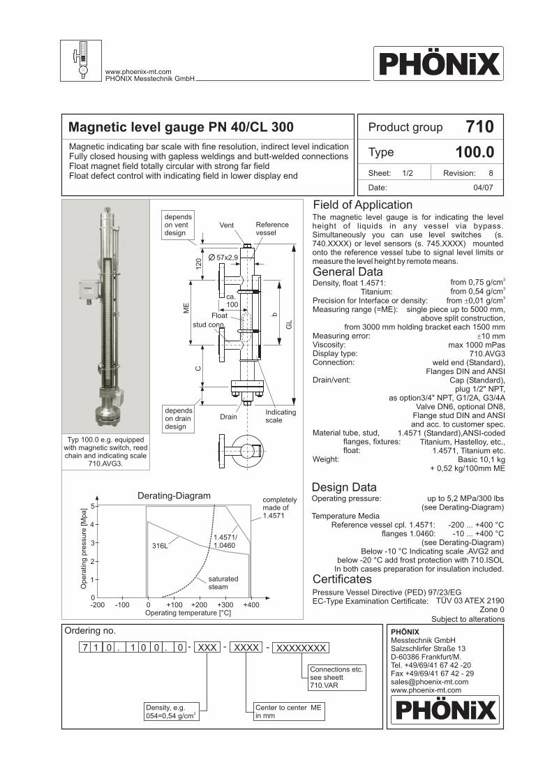
Typ 100.0 e.g. equippedwith magnetic switch, reedchain and indicating scale
710.AVG3.
Magnetic level gauge PN 40/CL 300 710
100.0Magnetic indicating bar scale with fine resolution, indirect level indicationFully closed housing with gapless weldings and butt-welded connectionsFloat magnet field totally circular with strong far fieldFloat defect control with indicating field in lower display end
Ordering no.
7 XXXXXXXXXXXXXXX1 0 . 1 0 .0 0 - - -
04/07
Density, float 1.4571:Titanium:
Precision for Interface or density:Measuring range (=ME):
Measuring error:Viscosity:Display type:Connection:
Drain/vent:
Material tube, stud,flanges, fixtures:float:
Weight:
Operating pressure:
Temperature MediaReference vessel cpl. 1.4571:
flanges 1.0460:
from 0,75 g/cmfrom
single piece up to 5000 mm,above split construction,
from 3000 mm holding bracket each 1500 mm10 mm
max 1000 mPas710.AVG3
weld end (Standard),
Cap (Standard),plug 1/2" NPT,
as option3/4" NPT, G1/2A, G3/4AValve DN6, optional DN8,
Flange stud DIN and ANSIand acc. to customer spec.
(Standard),Titanium, Hastelloy, etc.,
1.4571, Titanium etc.Basic 10,1 kg
+ 0,52 kg/100mm ME
3
0,54 g/cmfrom 0,01 g/cm
Flanges DIN and ANSI
1.4571 ANSI-coded
3
3±
±
up to 5,2 MPa/300 lbs(see Derating-Diagram)
- ... +400 °C200-10 ... +400 °C
(see Derating-Diagram)Below -10 °C Indicating scale .AVG2 and
below -20 °C add frost protection with 710.ISOLIn both cases preparation for insulation included.
General Data
Design Data
The magnetic level gauge is for indicating the levelheight of liquids in any vessel via bypass.Simultaneously you can use level switches (s.740.XXXX) or level sensors (s. 745.XXXX) mountedonto the reference vessel tube to signal level limits ormeasure the level height by remote means.
Connections etc.see sheett710.VAR
Density, e.g.054=0,54 g/cm
3
Center to center MEin mm
Subject to alterations
12
0
dependson ventdesign
Vent Referencevessel
57x2,9
ca.100
Float
stud conn.
dependson draindesign
Indicatingscale
Drain
ME
C
Field of Application
Product group
Type
Date:
Sheet: 1/2 Revision: 8
PHÖNiXwww.phoenix-mt.comPHÖNIX Messtechnik GmbH
PHÖNiX
PHÖNIXMesstechnik GmbHSalzschlirfer Straße 13D-60386 Frankfurt/M.Tel. +49/69/41 67 42 -20Fax +49/69/41 67 42 - [email protected]
TÜV 03 ATEX 2190Zone 0
Pressure Vessel Directive (PED) 97/23/EGEC-Type Examination Certificate:
Certificates
GL
b
Operating temperature [°C]
1
2
0-100
Derating-Diagram
+100 +200 +300 +400-200 0
completelymade of1.4571
1.4571/1.0460316L3
4
5
Op
era
tin
gp
ressu
re[M
pa
]
saturatedsteam
Details 710
100.0Float, Vent, Drain and Connection
04/07
Operating pressure:
Test pressure:Operating temperature:
There may be any other customer specified connections, materials and special floats.
CapFlangepiece
Flangepiece FlangeWeld end Threaded
end
Valve
Valve Valve sideways
Plug½ NPT
Plug½ NPT
up to 5,2 MPa/300 lbs(see Derating-Diagram for 1.4571)
Operating pressure x 1,3- ... +400 °C200
(see Derating-Diagram for 1.4571)
Design Data
Subject to alterations
Density range[g/cm ]
3
Density range[g/cm ]
3
Æ40
Æ40
Magnet-system
Magnet-system
Measure C[mm]
Measure C[mm]
Total length L[mm]
Total length L[mm]
Weight[g]
Weight[g]
Part no.
Part no
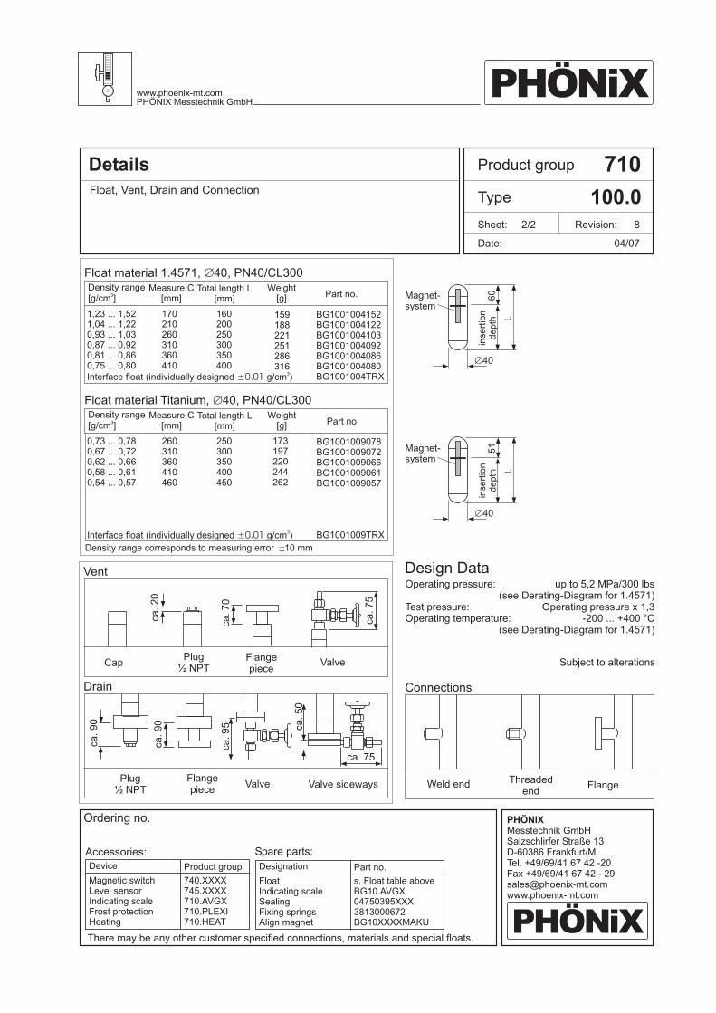
Density range corresponds to measuring error 10 mm±
Float material 1.4571, 40, PN40/CL300Æ
Float material Titanium, 40, PN40/CL300Æ
Vent
Drain Connections
Product group
Type
Date:
Sheet: 2/2 Revision: 8
LL
inse
rtio
nd
ep
thin
se
rtio
nd
ep
th6
05
1
DesignationDevice Part no.Product group
FloatIndicating scaleSealingFixing springsAlign magnet
Magnetic switchLevel sensorIndicating scaleFrost protectionHeating
s. Float table aboveBG10.AVGX04750395XXX3813000672BG10XXXXMAKU
740.XXXX745.XXXX710.AVGX710.PLEXI710.HEAT
Accessories: Spare parts:
Ordering no.
1,23 ... 1,521,04 ... 1,220,93 ... 1,030,87 ... 0,920,81 ... 0,860,75 ... 0,80
Interface float (individually designed g/cm )3
±0.01
170210260310360410
160200250300350400
159188221251286316
BG1001004152BG1001004122BG1001004103BG1001004092BG1001004086BG1001004080BG1001004TRX
0,73 ... 0,780,67 ... 0,720,62 ... 0,660,58 ... 0,610,54 ... 0,57
Interface float (individually designed g/cm )3
±0.01
260310360410460
250300350400450
173197220244262
BG1001009078BG1001009072BG1001009066BG1001009061BG1001009057
BG1001009TRX
PHÖNiXwww.phoenix-mt.comPHÖNIX Messtechnik GmbH
PHÖNiX
PHÖNIXMesstechnik GmbHSalzschlirfer Straße 13D-60386 Frankfurt/M.Tel. +49/69/41 67 42 -20Fax +49/69/41 67 42 - [email protected]
ca.20
ca.90
ca.95 ca.50
ca.75
ca. 75
ca.70
ca.
09
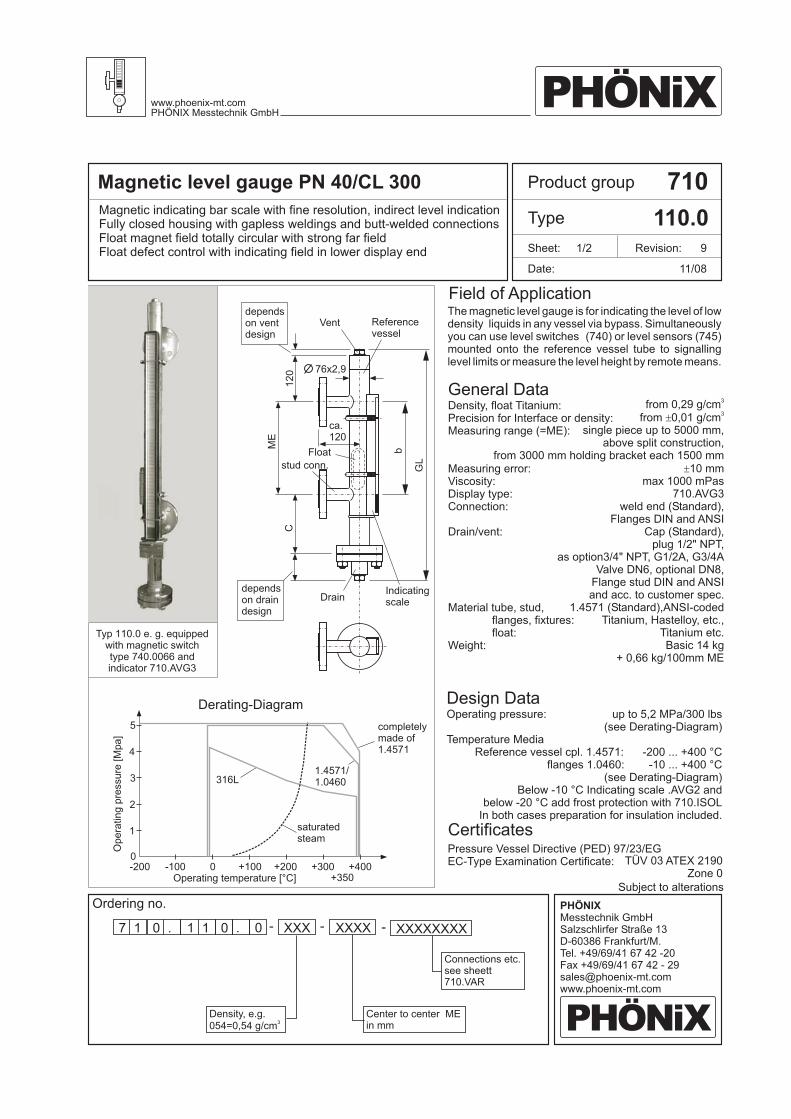
Magnetic level gauge PN 40/CL 300 710
110.0Magnetic indicating bar scale with fine resolution, indirect level indicationFully closed housing with gapless weldings and butt-welded connectionsFloat magnet field totally circular with strong far fieldFloat defect control with indicating field in lower display end
Ordering no.
7 XXXXXXXXXXXXXXX1 0 . 1 1 .0 0 - - -
11/08
Density, float Titanium:Precision for Interface or density:Measuring range (=ME):
Measuring error:Viscosity:Display type:Connection:
Drain/vent:
Material tube, stud,flanges, fixtures:float:
Weight:
Operating pressure:
Temperature MediaReference vessel cpl. 1.4571:
flanges 1.0460:
from 0,29 g/cm
single piece up to 5000 mm,above split construction,
from 3000 mm holding bracket each 1500 mm10 mm
max 1000 mPas710.AVG3
weld end (Standard),
Cap (Standard),plug 1/2" NPT,
as option3/4" NPT, G1/2A, G3/4AValve DN6, optional DN8,
Flange stud DIN and ANSIand acc. to customer spec.
(Standard),Titanium, Hastelloy, etc.,
Titanium etc.Basic 14 kg
+ 0,66 kg/100mm ME
3
from 0,01 g/cm
Flanges DIN and ANSI
1.4571 ANSI-coded
3±
±
up to 5,2 MPa/300 lbs(see Derating-Diagram)
- ... +400 °C200-10 ... +400 °C
(see Derating-Diagram)Below -10 °C Indicating scale .AVG2 and
below -20 °C add frost protection with 710.ISOLIn both cases preparation for insulation included.
General Data
Design Data
The magnetic level gauge is for indicating the level of lowdensity liquids in any vessel via bypass. Simultaneouslyyou can use level switches (740) or level sensors (745)mounted onto the reference vessel tube to signallinglevel limits or measure the level height by remote means.
Connections etc.see sheett710.VAR
Density, e.g.054=0,54 g/cm
3
Center to center MEin mm
Subject to alterations
12
0
dependson ventdesign
Vent Referencevessel
76x2,9
ca.120
Float
stud conn.
dependson draindesign
Indicatingscale
Drain
Operating temperature [°C]
Derating-Diagram
completelymade of1.4571
ME
C
Op
era
tin
gp
ressu
re[M
pa
]
Field of Application
Product group
Type
Date:
Sheet: 1/2 Revision: 9
saturatedsteam
1
2
0-100 +100 +200 +300
+350+400-200 0
1.4571/1.04603
4
5
PHÖNiXwww.phoenix-mt.comPHÖNIX Messtechnik GmbH
PHÖNiX
PHÖNIXMesstechnik GmbHSalzschlirfer Straße 13D-60386 Frankfurt/M.Tel. +49/69/41 67 42 -20Fax +49/69/41 67 42 - [email protected]
TÜV 03 ATEX 2190Zone 0
Pressure Vessel Directive (PED) 97/23/EGEC-Type Examination Certificate:
Certificates
316L
GL
b
Typ 110.0 e. g. equippedwith magnetic switchtype 740.0066 andindicator 710.AVG3
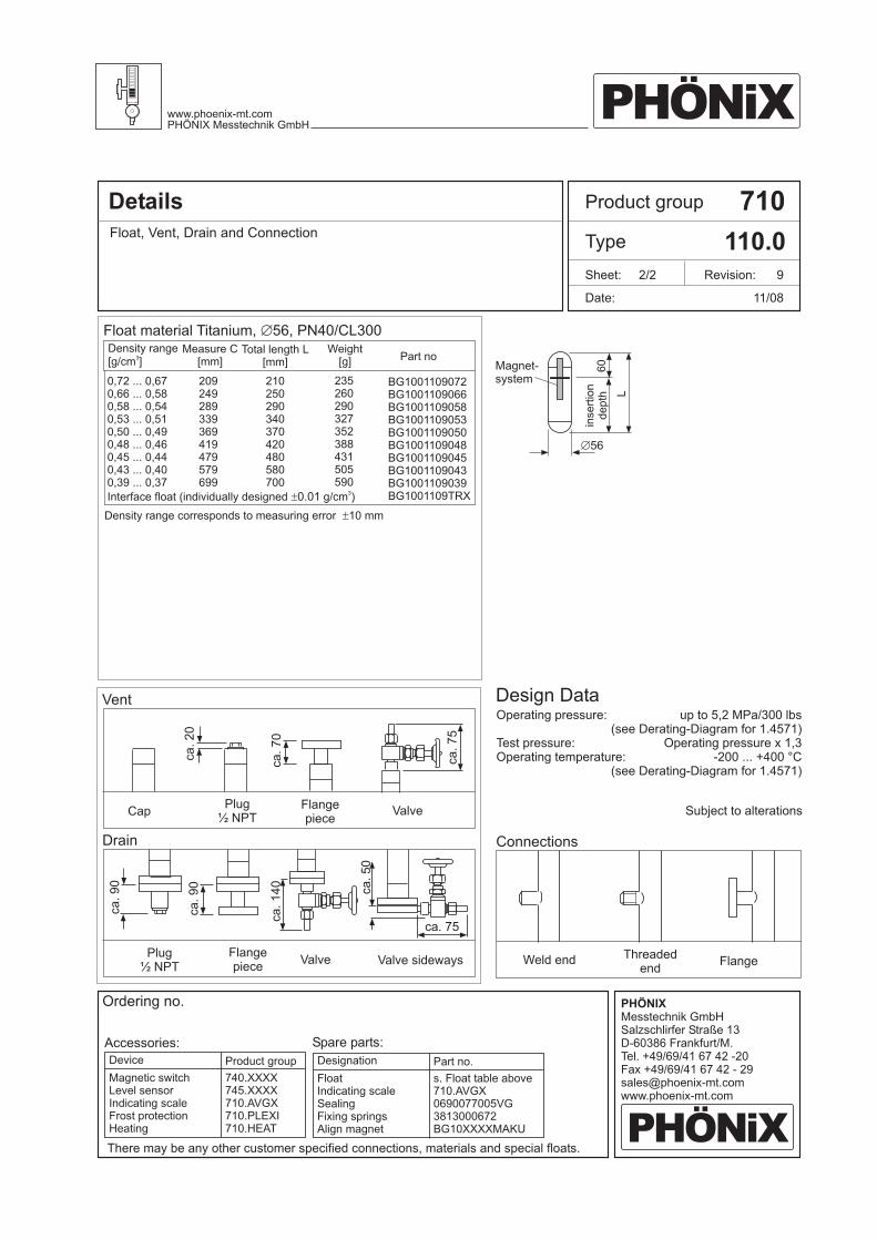
Details 710
110.0Float, Vent, Drain and Connection
11/08
Operating pressure:
Test pressure:Operating temperature:
There may be any other customer specified connections, materials and special floats.
CapFlangepiece
Flangepiece FlangeWeld end Threaded
end
Valve
Valve Valve sideways
Plug½ NPT
Plug½ NPT
up to 5,2 MPa/300 lbs(see Derating-Diagram for 1.4571)
Operating pressure x 1,3- ... +400 °C200
(see Derating-Diagram for 1.4571)
Design Data
Subject to alterations
Density range[g/cm ]
3
Æ56
Magnet-system
Measure C[mm]
Total length L[mm]
Weight[g] Part no
Density range corresponds to measuring error 10 mm±
Float material Titanium, 56, PN40/CL300Æ
Vent
Drain Connections
Product group
Type
Date:
Sheet: 2/2 Revision: 9
L
inse
rtio
nd
ep
th6
0
DesignationDevice Part no.Product group
FloatIndicating scaleSealingFixing springsAlign magnet
Magnetic switchLevel sensorIndicating scaleFrost protectionHeating
s. Float table above710.AVGX
3813000672BG10XXXXMAKU
0690077005VG
740.XXXX745.XXXX710.AVGX710.PLEXI710.HEAT
Accessories: Spare parts:
Ordering no.
0,72 ... 0,670,66 ... 0,580,58 ... 0,540,53 ... 0,510,50 ... 0,490,48 ... 0,460,45 ... 0,440,43 ... 0,400,39 ... 0,37
Interface float (individually designed g/cm )3
±0.01
209249289339369419479579699
210250290340370420480580700
235260290327352388431505590
BG1001109072BG1001109066BG1001109058BG1001109053BG1001109050BG1001109048BG1001109045BG1001109043BG1001109039BG1001109TRX
PHÖNiXwww.phoenix-mt.comPHÖNIX Messtechnik GmbH
PHÖNiX
PHÖNIXMesstechnik GmbHSalzschlirfer Straße 13D-60386 Frankfurt/M.Tel. +49/69/41 67 42 -20Fax +49/69/41 67 42 - [email protected]
ca.20
ca.75
ca.70
ca.90
ca.140
ca.50
ca. 75
ca.
09
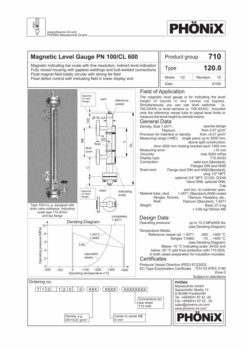
Magnetic Level Gauge PN 100/CL 600 710
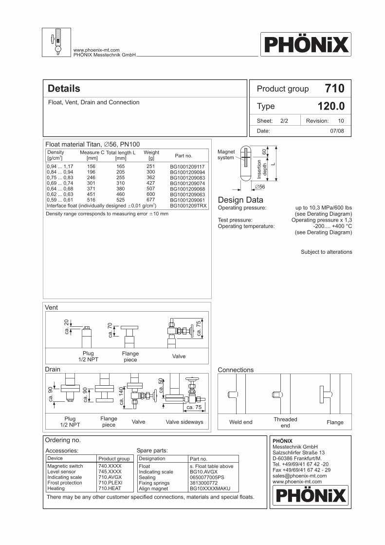
120.0
Ordering no.
7 XXXXXXXXXXXXXXX1 0 . 1 2 .0 0 - - -
07/08
Connections etc.see sheet710.VAR
Density, e.g.057=0,57 g/cm
3
Center to center MEin mm
Type 120.0 e. g. equipped withdrain valve sideways, indicating
scale type 710.AVG3and top flange
Operating temeperature [°C]
Derating-Diagram
completely1.4571
Op
era
tin
gp
ressu
re[M
Pa
]
Product group
Type
Date:
Sheet: 1/2 Revision: 10
Magnetic indicating bar scale with fine resolution, indirect level indicationFully closed housing with gapless weldings and butt-welded connectionsFloat magnet field totally circular with strong far fieldFloat defect control with indicating field in lower display end
Density, float 1.4571:Titanium:
Precision for Interface or density:Measuring range (=ME):
Measuring error:Viscosity:Display type:Connection:
Drain/vent:
Material tube, stud,flanges, fixtures:float:
Weight:
Operating pressure:
Temperature Media:Reference vessel cpl. 1.4571:
flanges 1.0460:
special designfrom
single piece up to 5000 mm,above split construction,
from 3000 mm holding bracket each 1500 mm10 mm
max 5000 mPas710.AVG3
weld end (Standard),
(Standard),plug 1/2" NPT,
optional 3/4" NPT, G1/2A, G3/4AValve DN8, optional DN6,
and acc. to customer spec.(Standard),
Titanium, Hastelloy, etc.,Titanium (Standard),
Basic 27,4 kg+ 0,66 kg/100mm ME
0,57 g/cmfrom 0,01 g/cm
Flanges DIN and ANSIFlange stud DIN and ANSI
Cap
1.4571 ANSI-coded
1.4571
3
3±
±
up to 10, MPa/600 lbs(see Derating-Diagram)
- ... +400 °C
3
200-10 ... +400 °C
(see Derating-Diagram)Below -10 °C Indicating scale .AVG2 and
below -20 °C add frost protection with 710.ISOLIn both cases preparation for insulation included.
General Data
Design Data
The magnetic level gauge is for indicating the levelheight of liquids in any vessel via bypass.Simultaneously you can use level switches (s.740.XXXX) or level sensors (s. 745.XXXX) mountedonto the reference vessel tube to signal level limits ormeasure the level height by remote means.
Subject to alterations
Field of Application
2
4
0-100 +100 +200 +300 +400-200 0
6
8
10
1.4571/1.0460
316L
saturatedsteam
PHÖNiXwww.phoenix-mt.comPHÖNIX Messtechnik GmbH
PHÖNiX
PHÖNIXMesstechnik GmbHSalzschlirfer Straße 13D-60386 Frankfurt/M.Tel. +49/69/41 67 42 -20Fax +49/69/41 67 42 - [email protected]
TÜV 03 ATEX 2190Zone 0
Pressure Vessel Directive (PED) 97/23/EGEC-Type Examination Certificate:
Certificates
12
0
dependson ventdesign
vent referencevessel
76,1x4
ca.165
float
studconn.
dependson draindesign
indicatingscale
drain
ME
C
GL
b
Details 710
120.0Float, Vent, Drain and Connection
07/08
Operating pressure:
Test pressure:Operating temperature:
Flangepiece
Flangepiece FlangeWeld end
Threadedend
Valve
Valve Valve sideways
Plug1/2 NPT
Plug1/2 NPT
up to 10, MPa/600 lbs(see Derating Diagram)
Operating pressure x 1,3- ... +400 °C
3
200.(see Derating Diagram)
Design Data
Subject to alterations
Æ56
Magnetsystem
Float material Titan, 56, PN100Æ
Vent
Drain Connections
Product group
Type
Date:
Sheet: 2/2 Revision: 10
L
Inse
rtio
nd
ep
th6
0
There may be any other customer specified connections, materials and special floats.
DesignationDevice Part no.Product group
FloatIndicating scaleSealingFixing springsAlign magnet
Magnetic switchLevel sensorIndicating scaleFrost protectionHeating
s. Float table aboveBG10.AVGX0650077005PS3813000772BG10XXXXMAKU
740.XXXX745.XXXX710.AVGX710.PLEXI710.HEAT
Accessories: Spare parts:
Ordering no.
PHÖNiXwww.phoenix-mt.comPHÖNIX Messtechnik GmbH
PHÖNiX
PHÖNIXMesstechnik GmbHSalzschlirfer Straße 13D-60386 Frankfurt/M.Tel. +49/69/41 67 42 -20Fax +49/69/41 67 42 - [email protected]
ca.20
ca.75
ca.70
ca.
09
ca.90
ca.140
ca.50
ca. 75
Density[g/cm ]
3
0,94 ... 1,170,84 ... 0,940,75 ... 0,830,69 ... 0,740,64 ... 0,680,62 ... 0,630,59 ... 0,61Interface float (individually designed 0,01 g/cm )
3±
156196246301371451516
165205255310380460525
251300362427507600677
BG1001209117BG1001209094BG1001209083BG1001209074BG1001209068BG1001209063BG1001209061BG1001209TRX
Measure C[mm]
Total length L[mm]
Weight[g] Part no.
Density range corresponds to measuring error 10 mm±

Magnetic Level Gauge PN 160/CL 900 710
130.0
Ordering no.
7 XXXXXXXXXXXXXXX1 0 . 1 3 .0 0 - - -
04/07
Connections etc.see sheet710.VAR
Density, e.g.057=0,57 g/cm
3
Center to center MEin mm
Operating temeperature [°C]
Op
era
tin
gp
ressu
re[M
Pa
]
Product group
Type
Date:
Sheet: 1/2 Revision: 9
Magnetic indicating bar scale with fine resolution, indirect level indicationIndicating elements permanent magnetic with stop pinFully closed housing with gapless weldingsFloat magnet field totally circular with strong far fieldFloat defect control with indication in lower display end
Density, float 1.4571:Titanium:
Precision for Interface or density:Measuring range (=ME):
Measuring error:Viscosity:Display type:Connection:
Drain/vent:
Material tube, stud,flanges, fixtures:float:
Weight:
Operating pressure:
Temperature Media:Reference vessel cpl. 1.4571:
flanges 1.0460:
special designfrom
single piece up to 5000 mm,above split construction,
from 3000 mm holding bracket each 1500 mm10 mm
max 5000 mPas710.AVG3
weld end (Standard),
(Standard),plug 1/2" NPT,
optional 3/4" NPT, G1/2A, G3/4AValve DN8, optional DN6,
and acc. to customer spec.(Standard),
Titanium, Hastelloy, etc.,Titanium (Standard),
Basic 30 kg+ 1,2 kg/100mm ME
0,51 g/cmfrom 0,01 g/cm
Flanges DIN and ANSIFlange stud DIN and ANSI
Cap
1.4571 ANSI-coded
1.4571
3
3±
±
up to 1 ,0 MPa/600 lbs(see Derating-Diagram)
- ... +400 °C
6
200-10 ... +400 °C
(see Derating-Diagram)Below -10 °C Indicating scale .AVG2 and
below -20 °C add frost protection with 710.ISOLIn both cases preparation for insulation included.
General Data
Design Data
The magnetic level gauge is for indicating the levelheight of liquids in any vessel via bypass.Simultaneously you can use level switches (s.740.XXXX) or level sensors (s. 745.XXXX) mountedonto the reference vessel tube to signal level limits ormeasure the level height by remote means.
Subject to alterations
Field of Application
saturatedsteam
PHÖNiXwww.phoenix-mt.comPHÖNIX Messtechnik GmbH
PHÖNiX
PHÖNIXMesstechnik GmbHSalzschlirfer Straße 13D-60386 Frankfurt/M.Tel. +49/69/41 67 42 -20Fax +49/69/41 67 42 - [email protected]
4
8
0-100 +100 +200 +300 +400-200 0
1.4571/1.0460
1212,5
10,5
16
completelymade of1.4571
TÜV 03 ATEX 2190Zone 0
Pressure Vessel Directive (PED) 97/23/EGEC-Type Examination Certificate:
Certificates
316L
Type 120.0 e. g. equipped withdrain valve sideways, indicating
scale type 710.AVG3and top flange
Derating-Diagram
13
5
dependson ventdesign
vent referencevessel
76,1x5
ca.165
float
studconn.
dependson draindesign
indicatingscale
drain
ME
C
GL
b
Details 710
130.0Float, Vent, Drain and Connection
04/07
Flangepiece
Flangepiece FlangeWeld end
Threadedend
Valve
Valve Valve sideways
Plug1/2 NPT
Plug1/2 NPT
Vent
Drain Connections
Product group
Type
Date:
Sheet: 2/2 Revision: 9
There may be any other customer specified connections, materials and special floats.
DesignationDevice Part no.Product group
FloatIndicating scaleSealingFixing springsAlign magnet
Magnetic switchLevel sensorIndicating scaleFrost protectionHeating
s. Float table above710.AVGX
3813000772BG10XXXXMAKU
0790101010PS
740.XXXX745.XXXX710.AVGX710.PLEXI710.HEAT
Accessories: Spare parts:
Ordering no.
PHÖNiXwww.phoenix-mt.comPHÖNIX Messtechnik GmbH
PHÖNiX
PHÖNIXMesstechnik GmbHSalzschlirfer Straße 13D-60386 Frankfurt/M.Tel. +49/69/41 67 42 -20Fax +49/69/41 67 42 - [email protected]
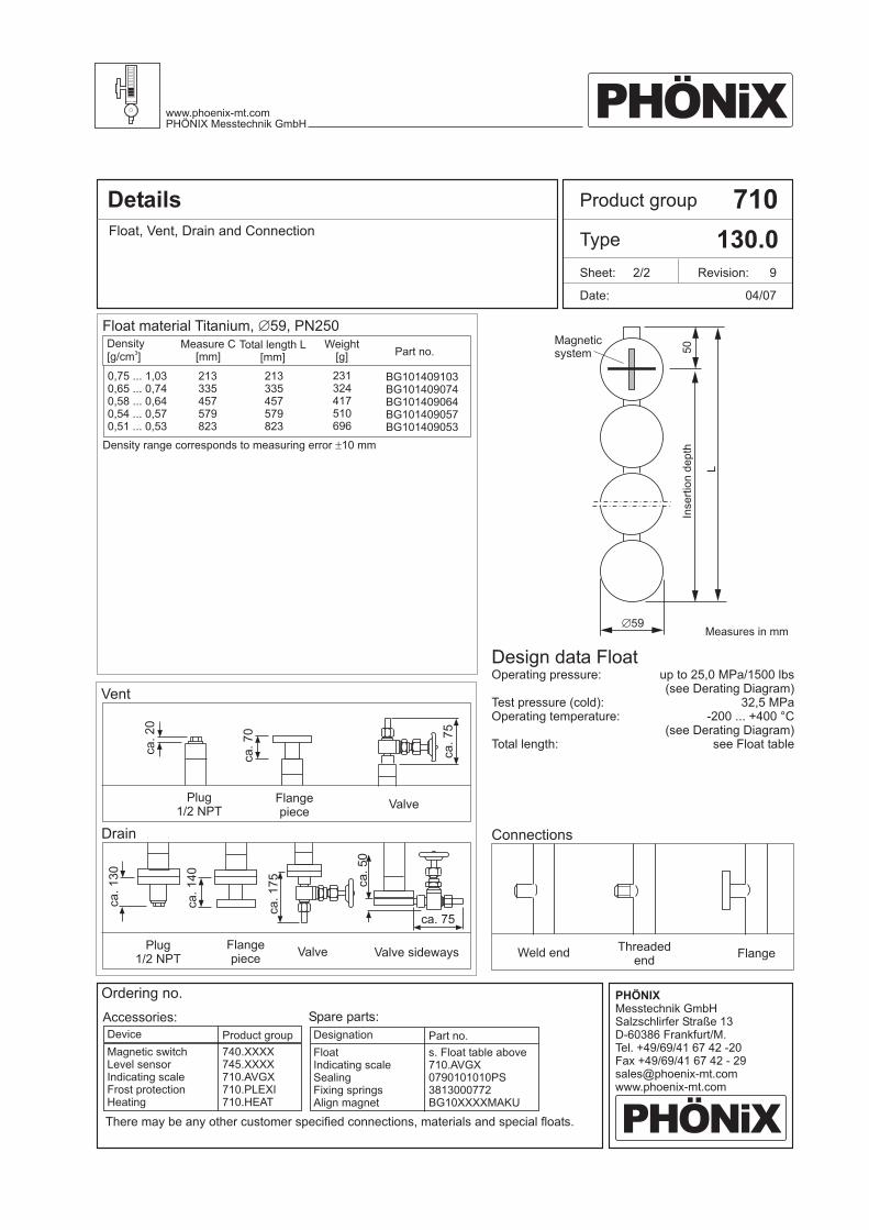
Operating pressure:
Test pressure (cold):Operating temperature:
Total length:
up to 25,0 MPa/1500 lbs(see Derating Diagram)
32,5 MPa- ... +400 °C200
(see Derating Diagram)see Float table
Design data Float
Magneticsystem
Measures in mm5Æ 9
50
L
Inse
rtio
nd
ep
th
Density[g/cm ]
3
Measure C[mm]
Total length L[mm]
Weight[g] Part no.
Density range corresponds to measuring error 10 mm±
Float material Titanium, 59, PN250Æ
0,75 ... 1,030,65 ... 0,740,58 ... 0,640,54 ... 0,570,51 ... 0,53
213335457579823
213335457579823
231324417510696
BG101409103BG101409074BG101409064BG101409057BG101409053
ca.20
ca.75
ca.70
ca.130
ca.140
ca.
75
1
ca.50
ca. 75

Magnetic Level Gauge PN 250/CL 1500 710
140.0Magnetic indicating bar scale with fine resolution, indirect level indicationIndicating elements permanent magnetic with stop pinFully closed housing with gapless weldingsFloat magnet field totally circular with strong far fieldFloat defect control with indication in lower display end
Ordering no.
7 XXXXXXXXXXXXXXX1 0 . 1 4 .0 0 - - -
04/07
Density::
:
Viscosity:Display type:Connection:
Drain/Vent:
Material tube, stud,flanges, fixtures:
Float:Weight:
Precision for Interface or densityMeasuring range (=ME)
Measuring error:
Operating pressure:
Temperature MediaReference vessel compl. 1.4571:
flanges 1.0460:
form
to 5000 mm,,
from 3000 mm holding bracket each 1500 mm10 mm
max 5000 mPas710.AVG3
weld end or
plug 1/2" NPT/capoptional 3/4" NPT, G1/2A, G3/4A,
Valve N 8, optional N 6,and acc. to customer spec.
SS 1.4571 (eq. 316Ti),optional,Hastelloy, etc.,
DIN + ANSI-materialsTitanium
Basic 32,5 kg+ 1,508 kg/100mm ME
0,51 g/cmfrom 0,1 g/cm
above split construction
Flanges DIN and ANSI
Flange stud DIN and ANSID D
Titanium
3
3±
±
up to 25 MPa/1500 lbs(see Derating-Diagram)
- ... +400 °C200-10 ... +400 °C
(see Derating-Diagram)Below -10 °C Indicating scale 710.AVG2
below -20 °C add frost protection with 710.ISOLIn both cases preparation for insulation included
General Data
Design Data
The magnetic level gauge is for indicating the levelheight or interface of liquids in any vessel via bypass.Simultaneously you can use level switches (s.740.XXXX) or level sensors (s. 745.XXXX) mountedonto the reference vessel tube to signal level limits ormeasure the level height by remote means.
Connections etc.see data sheet710.VAR
Density, e.g.057=0,57 g/cm
3
Center to center MEin mm
Subject to alterationsMedia temperature [°C]
5
10
0-100 +100 +200 +300 +400-200 0
completely1.4571(eq. 316Ti)
15
20
25
Op
era
tin
gp
ressu
re[M
Pa
]
Flanges1.0460 (CS)
saturatedwater steam
Field of Application
Product group
Type
Date:
Sheet: 1/2 Revision: 10
PHÖNiXwww.phoenix-mt.comPHÖNIX Messtechnik GmbH
PHÖNiX
PHÖNIXMesstechnik GmbHSalzschlirfer Straße 13D-60386 Frankfurt/M.Tel. +49/69/41 67 42 -20Fax +49/69/41 67 42 - [email protected]
TÜV 03 ATEX 2190Zone 0
P eqiupment directiveE - :
ressure (PED) 97/23/EGC Type Examination Certificate
Certificates
316L
Type 120.0 e. g. equipped withdrain valve sideways, indicating
scale type 710.AVG3and top flange
Derating-Diagram
13
5
dependson ventdesign
vent referencevessel
80x8,5
ca.165
float
studconn.
dependson draindesign
indicatingscale
drain
ME
C
GL
b
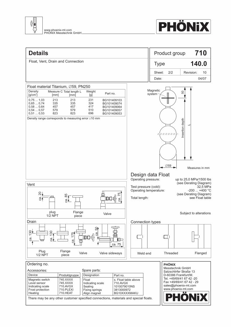
Details 710
140.0Float, Vent, Drain and Connection
04/07
Operating pressure:
Test pressure (cold):Operating temperature:
Total length:
There may be any other customer specified connections, materials and special floats.
Flangepiece
Flangepiece
FlangedWeld end Threaded
Valve
Valve Valve sideways
plug1/2 NPT
Plug1/2 NPT
up to 25,0 MPa/1500 lbs(see Derating Diagram)
32,5 MPa- ... +400 °C200
(see Derating Diagram)see Float table
Design data Float
Subject to alterations
Magneticsystem
Measures in mm5Æ 9
50
Vent
Drain Connection types
Product group
Type
Date:
Sheet: 2/2 Revision: 10
L
Inse
rtio
nd
ep
th
DesignationDevice Part no.Produktgruppe
FloatIndicating scaleSealingFixing springsAlign magnet
Magnetic switchLevel sensorIndicating scaleFrost protectionHeating
s. Float table above710.AVGX1010079010NS3813000972BG10XXXXMAKU
740.XXXX745.XXXX710.AVGX710.PLEXI710.HEAT
Accessories: Spare parts:
Ordering no.
PHÖNiXwww.phoenix-mt.comPHÖNIX Messtechnik GmbH
PHÖNiX
PHÖNIXMesstechnik GmbHSalzschlirfer Straße 13D-60386 Frankfurt/M.Tel. +49/69/41 67 42 -20Fax +49/69/41 67 42 - [email protected]
Density[g/cm ]
3
Measure C[mm]
Total length L[mm]
Weight[g] Part no.
Density range corresponds to measuring error 10 mm±
Float material Titanium, 59, PN250Æ
0,75 ... 1,030,65 ... 0,740,58 ... 0,640,54 ... 0,570,51 ... 0,53
213335457579823
213335457579823
231324417510696
BG101409103BG101409074BG101409064BG101409057BG101409053
ca.20
ca.75
ca.85
ca.130
ca.130
ca.
75
1
ca.50
ca. 75
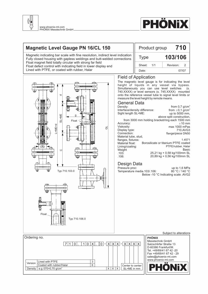
Magnetic Level Gauge PN 16/CL 150 710
103/106Magnetic indicating bar scale with fine resolution, indirect level indicationFully closed housing with gapless weldings and butt-welded connectionsFloat magnet field totally circular with strong far fieldFloat defect control with indicating field in lower display endLined with PTFE, or coated with rubber, Halar 07/07
Density:Interface/density difference:Sight length SL=ME:
Accuracy:Viskosity:Display type:Connection:Material tube, stud,flanges, fixtures:Material float:Lining/coating:Weight.103:.106:
Pressure proc:Temperature media.103/.106:
from 0,7 g/cmfrom 0,1 g/cmup to 5000 mm,
above split construction,from 3000 mm holding bracket/ring each 1500 mm
10 mmmax 1000 mPas
710.AVG3f ge/piece
Borosilicate or titanium PTFE coated/
Basic25,21 kg + 0,58 kg/100mm SL20,89 kg + 0,56 kg/100mm SL
3
3
N50
1.4571
PTFE rubber, Halar
±
±
lan D
up to 1,6 MPa80 °C / 140 °C
Below -10 °C Indicating scale .AVG2
General Data
Design Data
The magnetic level gauge is for indicating the levelheight of liquids in any vessel via bypass.Simultaneously you can use level switches (s.740.XXXX) or level sensors (s. 745.XXXX) mountedonto the reference vessel tube to signal level limits ormeasure the level height by remote means.
Subject to alterations
Field of Application
Product group
Type
Date:
Sheet: 1/1 Revision: 2
PHÖNiXwww.phoenix-mt.comPHÖNIX Messtechnik GmbH
PHÖNiX
PHÖNIXMesstechnik GmbHSalzschlirfer Straße 13D-60386 Frankfurt/M.Tel. +49/69/41 67 42 -20Fax +49/69/41 67 42 - [email protected]
Ordering no.
7 1 0 . 1 0 .X 0 X XX XX X X- -
e.g.070=0,70 g/cm3
Density XCenter to centerSL=ME in mmX X
VersionCoated with rubber/Halar
Lined with PTFE 3
6
D
Float
Typ 710.103.0
SL
=M
EC
d
g
L=
ME
+d
GL
Typ 710.106.0
Float
D
Float
SL=
ME
Cd
g
L=
ME
+c+
d
Standardversion
Specialversion
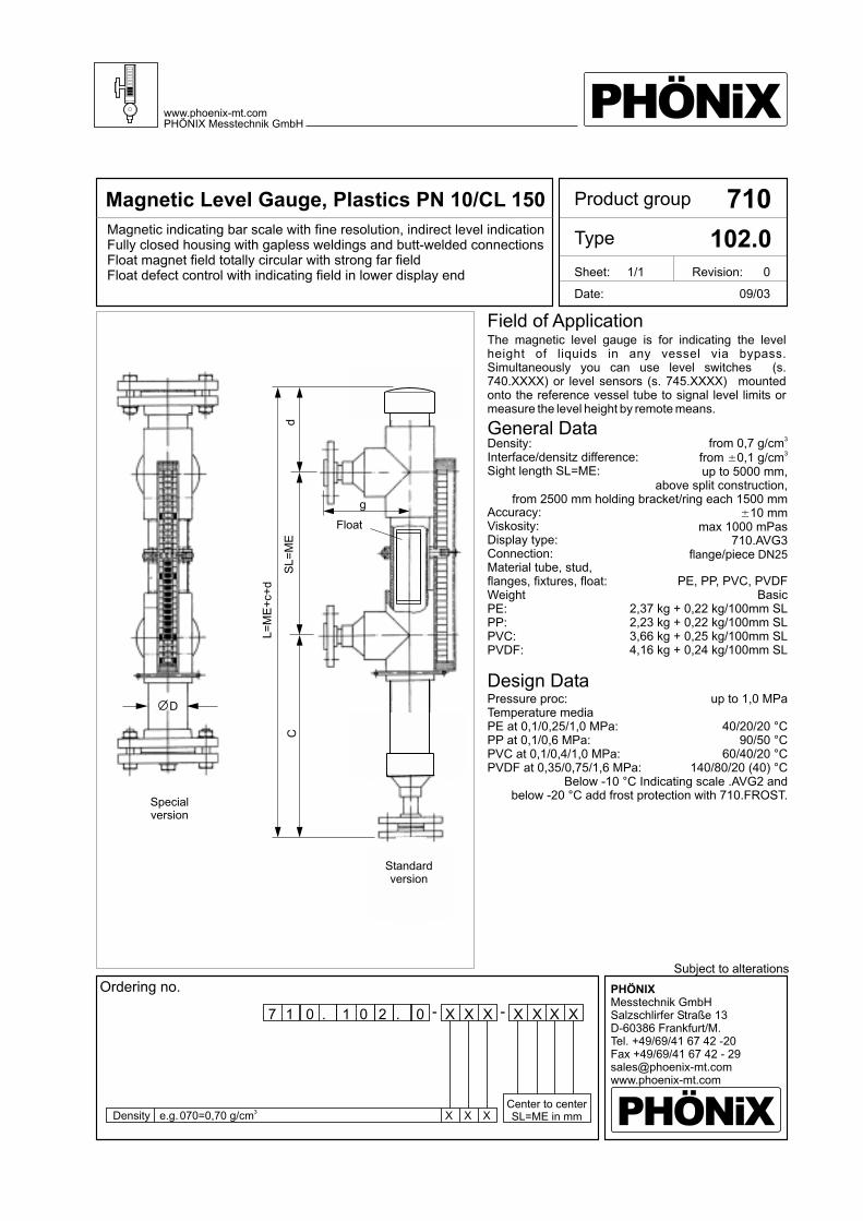
Magnetic Level Gauge, Plastics PN 10/CL 150 710
102.0Magnetic indicating bar scale with fine resolution, indirect level indicationFully closed housing with gapless weldings and butt-welded connectionsFloat magnet field totally circular with strong far fieldFloat defect control with indicating field in lower display end
09/03
Density:Interface/densitz difference:Sight length SL=ME:
Accuracy:Viskosity:Display type:Connection:Material tube, stud,flanges, fixtures, float:WeightPE:PP:PVC:PVDF:
Pressure proc:Temperature mediaPE at 0,1/0,25/1,0 MPa:PP at 0,1/0,6 MPa:PVC at 0,1/0,4/1,0 MPa:PVDF at 0,35/0,75/1,6 MPa:
from 0,7 g/cmfrom 0,1 g/cmup to 5000 mm,
above split construction,from 2500 mm holding bracket/ring each 1500 mm
10 mmmax 1000 mPas
710.AVG3f ge/piece
PE, PP, PVC, PVDFBasic
2,37 kg + 0,22 kg/100mm SL2,23 kg + 0,22 kg/100mm SL3,66 kg + 0,25 kg/100mm SL4,16 kg + 0,24 kg/100mm SL
3
3
N
±
±
lan D 25
up to 1,0 MPa
40/20/20 °C90/50 °C
60/40/20 °C140/80/20 (40) °C
Below -10 °C Indicating scale .AVG2 andbelow -20 °C add frost protection with 710.FROST.
General Data
Design Data
The magnetic level gauge is for indicating the levelheight of liquids in any vessel via bypass.Simultaneously you can use level switches (s.740.XXXX) or level sensors (s. 745.XXXX) mountedonto the reference vessel tube to signal level limits ormeasure the level height by remote means.
Subject to alterations
Field of Application
Product group
Type
Date:
Sheet: 1/1 Revision: 0
PHÖNiXwww.phoenix-mt.comPHÖNIX Messtechnik GmbH
PHÖNiX
PHÖNIXMesstechnik GmbHSalzschlirfer Straße 13D-60386 Frankfurt/M.Tel. +49/69/41 67 42 -20Fax +49/69/41 67 42 - [email protected]
Ordering no.
7 1 0 . 1 0 .2 0 X XX XX X X- -
e.g.070=0,70 g/cm3
Density XCenter to centerSL=ME in mmX X
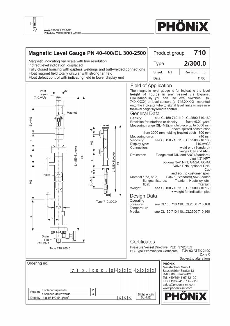
Magnetic Level Gauge PN 40-400/CL 300-2500 710
2/300.0
Ordering no.
11/03
Product group
Type
Date:
Sheet: 1/1 Revision: 0
Magnetic indicating bar scale with fine resolutionindirect level indication, displacedFully closed housing with gapless weldings and butt-welded connectionsFloat magnet field totally circular with strong far fieldFloat defect control with indicating field in lower display end
Density:Precision for Interface or density:Measuring range (SL=ME):
Measuring error:Viscosity:Display type:Connection:
Drain/vent:
Material tube, stud,flanges, fixtures:float:
Weight:
Operatingpressure:TemperatureMedia:
see CL150 710.110...CL2500 710.160from 0,01 g/cm
ted
Flanges DIN and ANSIFlange stud DIN and ANSI
Cap
1.4571 ANSI-coded
3
single piece up to 5000 mmabove split construction
from 3000 mm holding bracket each 1500 mm10 mm
710.AVG3weld end (Standard),
(Standard),plug 1/2" NPT,
optional 3/4" NPT, G1/2A, G3/4AValve DN8, optional DN6,
and acc. to customer spec.(Standard),
Titanium, Hastelloy, etc.,Titanium
+ weight for indication pipe
±
±
see CL150 710.110...CL2500 710.160
see CL150 710.110...CL2500 710.160
see CL150 710.110...CL2500 710.160
see CL150 710.110...CL2500 710.160
TÜV 03 ATEX 2190Zone 0
General Data
Design Data
The magnetic level gauge is for indicating the levelheight of liquids in any vessel via bypass.Simultaneously you can use level switches (s.740.XXXX) or level sensors (s. 745.XXXX) mountedonto the indicator tube to signal level limits or measurethe level height by remote control.
Subject to alterations
Pressure Vessel Directive (PED) 97/23/EGEC-Type Examination Certificate:
Certificates
Field of Application
PHÖNiXwww.phoenix-mt.comPHÖNIX Messtechnik GmbH
PHÖNiX
PHÖNIXMesstechnik GmbHSalzschlirfer Straße 13D-60386 Frankfurt/M.Tel. +49/69/41 67 42 -20Fax +49/69/41 67 42 - [email protected]
Float
Type 710.200.0
Drainsee
710.VAR
Ventsee
710.VAR
Type 710.300.0
Magnet
d
g
D
S
N N
S
ME
ME
d
d
e
e
SL
=M
E
SL
=M
E
L=
ME
+S
L+
c+
e
L=
ME
+S
L+
c+
e
GL
GL
c
c
7 1 0 . X 0 .0 0 X XX XX X X- -
e.g.054=0,54 g/cm3
Density
Versiondisplaced downwards
displaced upwards
XSight length
SL=ME
2
3
X X

Magnetic Level Gauge PN 16-400/CL 150-2500 710
22X.0Magnetic indicating bar scale with fine resolution, indirect level indication
Indicating elements permanent magnetic with stop pinFloat magnet field totally circular with strong far fieldFloat defect control with indication in lower display end
Indicating scale above containment
Ordering no.7 1 0 . 2 2 .X X X XX XX X X- -
9/08
D .2/ i :
Sight length:
:.2
.220/1/2/3:
ensity 20/1/2/3:Interface d fference of density
:AccuracyViscosity:Display type:Connection:
DN min.220/1/2/3:Material tube, stud,flanges, fixtures, wire/tube guide:
FloatFloat d 20/1/2/3:Weight
P proc .2 :Temperature media
f
ressure 20/1/2/3
Reference vessel compl. 1.4571:langes 1.0460:
from 0,7/0,6/0,7/0,7 g/cm
10 mmmax 1000 mPas
710.AVG3orc
kg+ 0, kg/100mm
3
from 0,1 g/cmplease request
flange-piecedire t
40/65/100/125
SS 1.4571optional,Hastelloy, Titanium etc
DIN + ANSI-materials1.4571, titanium
40/56/85/108 mmBasic
22,77/18,27/16,77/12,2772 SL
3±
±
up to 40,0
200-10 ... +400 °C
Below -10 °C Indicating scale 710.AVG2below -20 °C add frost protection with 710.ISOLIn both cases preparation for insulation included
MPa
- ... +400 °C
TÜV 03 ATEX 2190Zone 0
General Data
Design Data
The magnetic level gauge is for indicating the levelheight or interface of liquids in any vessel. Simul-taneously you can use level switches (s. 740.XXXX) orlevel sensors (s. 745.XXXX) mounted onto the gaugetube to signal level limits or measure the level height byremote control.
z.B.054=0,54 g/cm3
Density
Versiondirect, wire as float guide
all other connections
thread connection
Flange-piece, tube as float guide
Flange-piece, wire as float guide
direct, tube as float guide
XSight length
SL
0
1
2
3
0
5
X X
Subject to alterations
Field of Application
Product group
Type
Date:
Sheet: 1/1 Revision: 1
P eqiupment directive
E - :
ressure(PED) 97/23/EG
C Type Examination Certificate
Certificates
PHÖNiXwww.phoenix-mt.comPHÖNIX Messtechnik GmbH
PHÖNiX
PHÖNIXMesstechnik GmbHSalzschlirfer Straße 13D-60386 Frankfurt/M.Tel. +49/69/41 67 42 -20Fax +49/69/41 67 42 - [email protected]
Type710.221.0
Type710.220.0
Type710.222.0
Type710.223.0
a
GL
=S
L+
a+
e+
20
0
12
0
h
DN
150
d
d Float
eS
L
150
Type710.22X.5
PHÖNiXwww.phoenix-mt.comPHÖNIX Messtechnik GmbH
PHÖNiX
PHÖNIXMesstechnik GmbHSalzschlirfer Straße 13D-60386 Frankfurt/M.Tel. +49/69/41 67 42 -20Fax +49/69/41 67 42 - [email protected]
Type710.320.0
Type710.321.0
Type710.322.0
Type710.323.0
a
GL
=S
L+
a+
e+
20
0
12
0
h
DN
150150
d
dFloat
eS
L
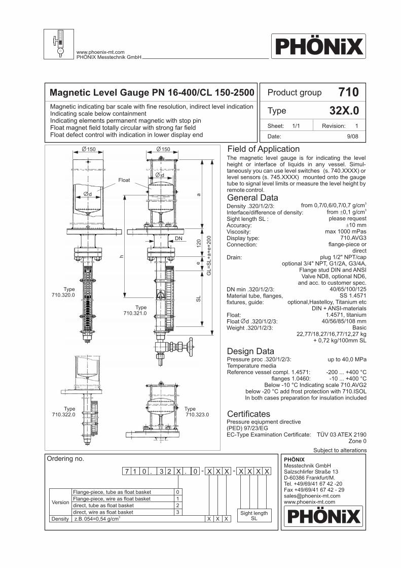
Magnetic Level Gauge PN 16-400/CL 150-2500 710
32X.0Magnetic indicating bar scale with fine resolution, indirect level indication
Indicating elements permanent magnetic with stop pinFloat magnet field totally circular with strong far fieldFloat defect control with indication in lower display end
Indicating scale below containment
9/08
Product group
Type
Date:
Sheet: 1/1 Revision: 1
D ./ i :
S SL:
:.
. 20/1/2/3:
ensity 320/1/2/3:Interface d fference of density
ight length :AccuracyViscosity:Display type:Connection:
Drain:
DN min .320/1/2/3:Material tube, flanges,fixtures, guide:
FloatFloat d 320/1/2/3:Weight 3
P proc .3 :Temperature media
f
ressure 20/1/2/3
Reference vessel compl. 1.4571:langes 1.0460:
from 0,7/0,6/0,7/0,7 g/cm
10 mmmax 1000 mPas
710.AVG3orc
kg+ 0, kg/100mm
3
from 0,1 g/cmplease request
flange-piecedire t
plug 1/2" NPT/capoptional 3/4" NPT, G1/2A, G3/4A,
Flange stud DIN and ANSIValve ND8, optional ND6,
and acc. to customer spec.40/65/100/125
SS 1.4571optional,Hastelloy, Titanium etc
DIN + ANSI-materials1.4571, titanium
40/56/85/108 mmBasic
22,77/18,27/16,77/12,2772 SL
3±
±
up to 40,0
200-10 ... +400 °C
Below -10 °C Indicating scale 710.AVG2below -20 °C add frost protection with 710.ISOLIn both cases preparation for insulation included
MPa
- ... +400 °C
TÜV 03 ATEX 2190Zone 0
General Data
Design Data
The magnetic level gauge is for indicating the levelheight or interface of liquids in any vessel. Simul-taneously you can use level switches (s. 740.XXXX) orlevel sensors (s. 745.XXXX) mounted onto the gaugetube to signal level limits or measure the level height byremote control.
Subject to alterations
Field of Application
P eqiupment directive
E - :
ressure(PED) 97/23/EG
C Type Examination Certificate
Certificates
Ordering no.
7 1 0 . 3 2 .X 0 X XX XX X X- -
z.B.054=0,54 g/cm3
Density
Version
direct, wire as float basket
Flange-piece, tube as float basket
Flange-piece, wire as float basket
direct, tube as float basket
XSight length
SL
0
1
2
3
X X
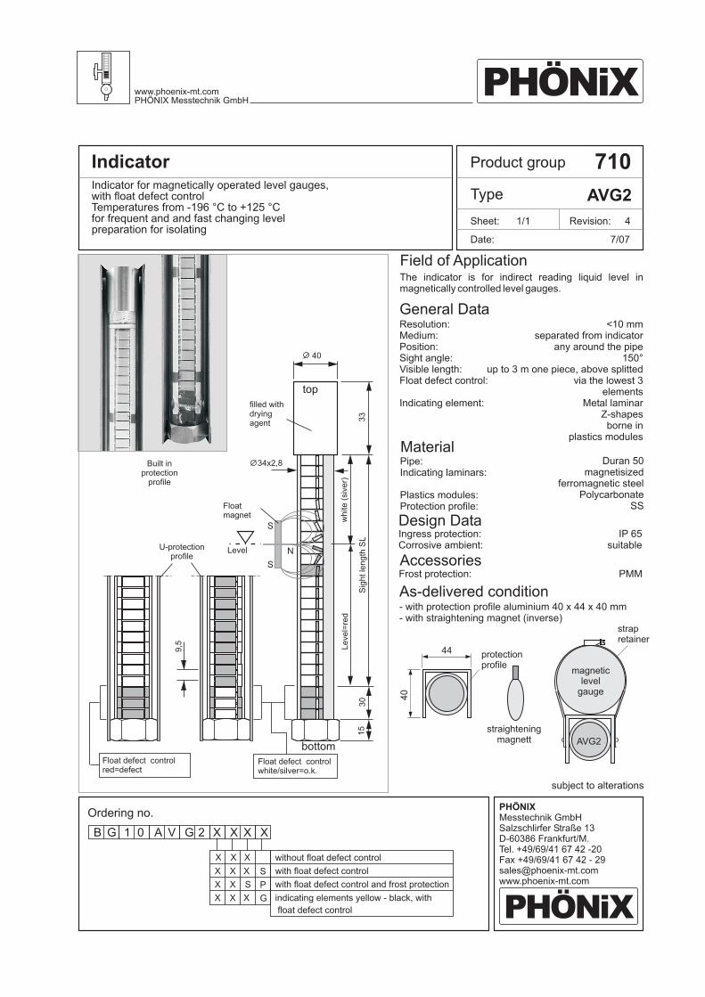
Product groupIndicator 710
Type AVG2Indicator for magnetically operated level gauges,with float defect controlTemperatures from -196 °C to +125 °Cfor frequent and and fast changing levelpreparation for isolating
General Data
Field of Application
Date:
Revision: 4
7/07
Sheet: 1/1
Material
Design DataIngress protection:Corrosive ambient:
Resolution:Medium:Position:Sight angle:Visible length:Float defect control:
Indicating element:
Pipe:Indicating laminars:
Plastics modules:Protection profile:
Built inprotection
profile
<10 mmseparated from indicator
any around the pipe150°
up to 3 m one piece, above splittedvia the lowest 3
elementsMetal laminar
Z-shapesborne in
plastics modules
Duran 50magnetisized
ferromagnetic steelPolycarbonate
SS
IP 65suitable
subject to alterations
The indicator is for indirect reading liquid level inmagnetically controlled level gauges.
Ordering no.
B G 1 0 XA XV XG X2
without float defect control
with float defect control
indicating elements yellow - black, with
float defect control
with float defect control and frost protection
S
G
X
X
X
X
X
X
X
X
X
PX SX
PHÖNiXwww.phoenix-mt.comPHÖNIX Messtechnik GmbH
PHÖNiX
PHÖNIXMesstechnik GmbHSalzschlirfer Straße 13D-60386 Frankfurt/M.Tel. +49/69/41 67 42 -20Fax +49/69/41 67 42 - [email protected]
Float defect controlwhite/silver=o.k.
Level=
red
white
(siv
er)
Sig
htle
ngth
SL
9,5
34x2,8
40
Level
Float defect controlred=defect
Floatmagnet
filled withdryingagent
U-protectionprofile
N
S
S
bottom
30
15
33
top
AccessoriesFrost protection: PMM
protectionprofile
44
40
straighteningmagnett
strapretainer
magneticlevel
gauge
AVG2
As-delivered condition- with protection profile aluminium 40 x 44 x 40 mm- with straightening magnet (inverse)
Ordering no.
subject to alterations
B G 1 0 XA XV XG X3
without float defect control
with float defect control
indicating elements yellow - black, with
float defect control
with float defect control and frost protection
S
G
X
X
X
X
X
X
X
X
X
PX SX
PHÖNiXwww.phoenix-mt.comPHÖNIX Messtechnik GmbH
PHÖNiX
PHÖNIXMesstechnik GmbHSalzschlirfer Straße 13D-60386 Frankfurt/M.Tel. +49/69/41 67 42 -20Fax +49/69/41 67 42 - [email protected]
Indicator
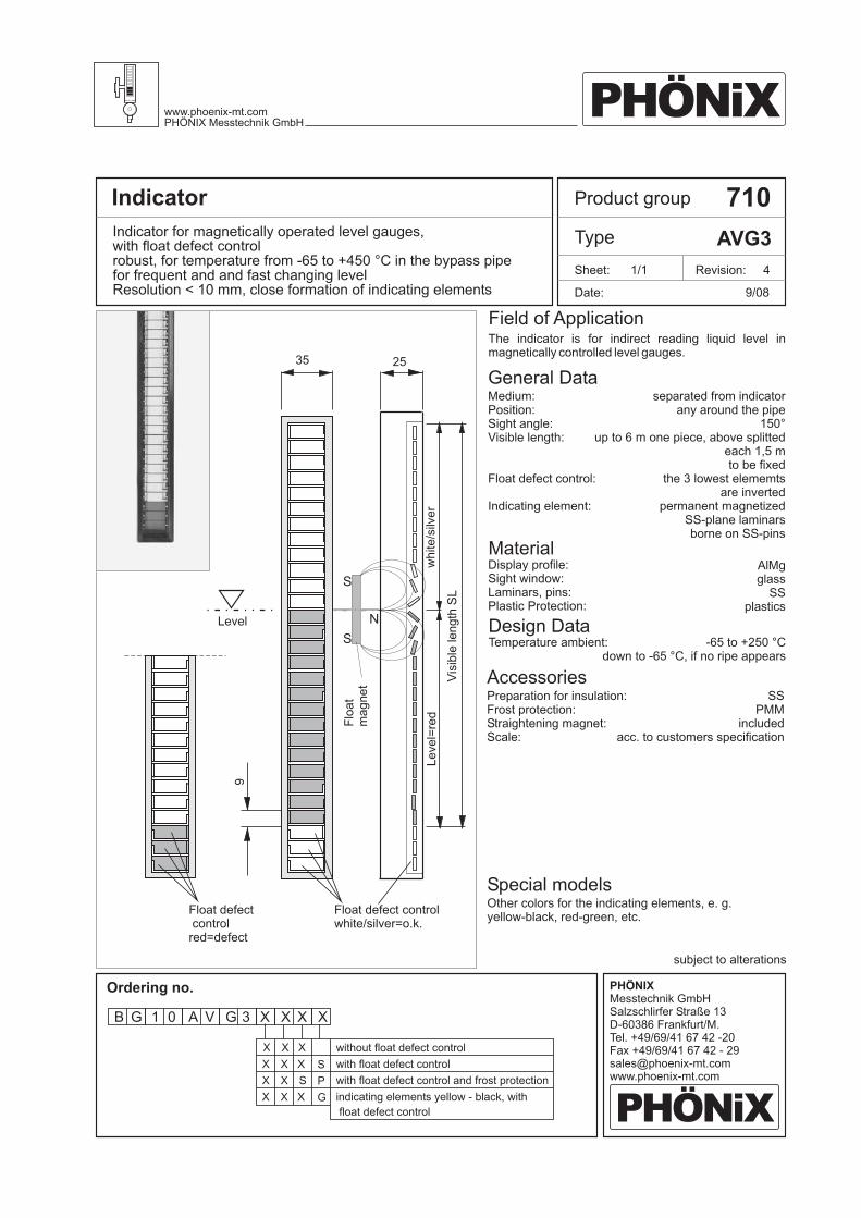
Indicator for magnetically operated level gauges,with float defect controlrobust, for temperature from -65 to +450 °C in the bypass pipefor frequent and and fast changing levelResolution < 10 mm, close formation of indicating elements
Product group 710
Type AVG3
Date:
Revision: 4
9/08
Sheet: 1/1
General Data
Field of Application
Material
Design DataTemperature ambient:
Medium:Position:Sight angle:Visible length:
Float defect control:
Indicating element:
Display profile:Sight window:Laminars, pins:Plastic Protection:
separated from indicatorany around the pipe
150°up to 6 m one piece, above splitted
each 1,5 mto be fixed
the 3 lowest elememtsare inverted
permanent magnetizedSS-plane laminarsborne on SS-pins
AlMgglass
SSplastics
-65 to +250 °Cdown to -65 °C, if no ripe appears
Accessories
Special models
Preparation for insulation:Frost protection:Straightening magnet:Scale:
Other colors for the indicating elements, e. g.yellow-black, red-green, etc.
SSPMM
includedacc. to customers specification
The indicator is for indirect reading liquid level inmagnetically controlled level gauges.
9
Level
Float defectcontrolred=defect
Float defect controlwhite/silver=o.k.
Vis
ible
length
SL
35
white/s
ilver
25
S
N
S
Level=
red
Flo
at
magnet
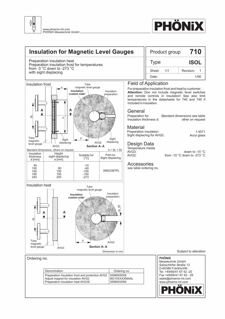
Product groupInsulation for Magnetic Level Gauges 710
Type ISOLPreparation insulation heata frost for temperatures
from 0 °C down to -273 °Cwith sight displacing
Prep ration insulation
General
Field of Application
Date:
Revision: 1
1/06
Sheet: 1/1
Material
Design DataTemperature mediaAVG3:AVG2:
Preparation forInsulation thickness d:
Preparation insulation:Sight displacing for AVG2:
AVG2
AVG3
Dimension in mm
b = SL + 50Standard dimensions, others on request
Tubemagnetic level gauge
Tubemagnetic level gauge
Tubemagneticlevel gauge
Tubemagneticlevel gauge
AVG2
AVG3
Insulationpreparation
Insulationpreparation
Insulationcustom side!
Insulationcustom side!
Sightdisplacing
Sightdisplacing
a
d
d
Section A- A
Section A- A
A
A
A
A
Standard dimensions see tableother on request
1.4571Acryl glass
down to -10 °Cfrom -10 °C down to -273 °C
Accessoriessee table ordering no.
Subject to alteration
For preparation insulation frost and heat by customer.Don not include magnetic level switches
and remote controls in insulation! See also limittemperatures in the datasheets for 740 and 745 ifincluded in insulation.
Attention:
Ordering no.
Insulation frost
Insulation heat
PHÖNiXwww.phoenix-mt.comPHÖNIX Messtechnik GmbH
PHÖNiX
PHÖNIXMesstechnik GmbHSalzschlirfer Straße 13D-60386 Frankfurt/M.Tel. +49/69/41 67 42 -20Fax +49/69/41 67 42 - [email protected]
Denomination
Preparation insulation frost and protection AVG2Adjust magnet for insulation AVG2Preparation insulation heat AVG3S
Ordering no.
5598005059BG10XXXXMAAL5598003059
bSL
SL
ca.40
I s
d
n ulationthickness
[mm]
H
a
eightsight displacing
[mm]
Part-no.Sight displacing
Suitable for[°C]
40100140190240
-10-60
-100-150-273
60100150200
39823387PL
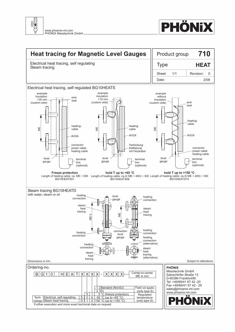
Product groupHeat tracing for Magnetic Level Gauges 710
Type HEATElectrical heat tracing, self regulatingSteam tracing
Date:
Revision: 0
2/08
Sheet: 1/1
Dimensions in mm Subject to alterations
Ordering-no.
Electrical heat tracing, self regulated BG10HEATS
Steam tracing BG10HEATDwith water, steam or oil
PHÖNiXwww.phoenix-mt.comPHÖNIX Messtechnik GmbH
PHÖNiX
PHÖNIXMesstechnik GmbHSalzschlirfer Straße 13D-60386 Frankfurt/M.Tel. +49/69/41 67 42 -20Fax +49/69/41 67 42 - [email protected]
AVGX AVGX AVGX
heating-cable
examplensulation
(custom side)
i>30 mm
exampleinsulation
(custom side)>10 mm
examplewithout
Insulation(custom side)
heating-cable
heating-cable
end-seal
end-seal
connectorpower cableheating cable
VerbindungKaltleitungmit Heizkabel
connectorpower cableheating cable
terminalbox(optional)
Freeze protectionca. ME + 500
BG10HEATS01Length of heating cable:
hold T up to +65 °Cca.2( ME + 400) + 300
BG10HEATS06Length of heating cable:
hold T up to +150 °CLength of heating cable: ca.3( ME + 400) + 300
BG10HEATS15
terminalbox(optional)
terminalbox(optional)
levelgauge
levelgauge
levelgauge
ME
ME
ME
heatingconnection
heatingconnection
levelgauge
heatingconnection
heatingconnection(alternative)
heatingconnection
heatingconnection
steamheat
tracing
steamheat
tracing
steamheattracing
steamheattracing(alternative)
connectionlevel
gauge
ME
ME
h
GB 1 0 . H E A T X X XX XX - X X
SD
001
165
12
Regulatedtemperature(only type S)
Field od applic.(only type S)
Steam hElectrical, self regulating
eat tracing
Further execution and more exact technical data on request
5 °C ( )65
150
freeze protection°C (up to +65 °C)°C (up to +150 °C)
Standard ( )Ex
Not-Ex
Center-to-centerME in mm
Tech-nology