Embed Size (px)
Citation preview
8/3/2019 Piezoresistive Sensors 11-4-2011
http://slidepdf.com/reader/full/piezoresistive-sensors-11-4-2011 1/21
Piezoresistive Sensors
Origin and expression of piezoresistivity
The resistance of a resistor:
A
L R
The resistance changes with the changesin geometry and resistivity.
The change in resistance is much greaterdue to the change in resistivity.
A
A
l
l
R
R
8/3/2019 Piezoresistive Sensors 11-4-2011
http://slidepdf.com/reader/full/piezoresistive-sensors-11-4-2011 2/21
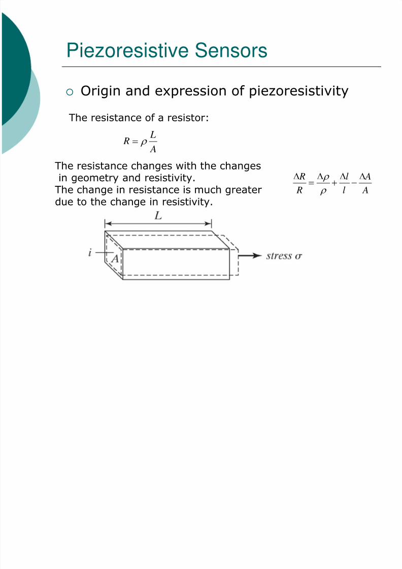
Expression of piezoresistivity
Resistivity of a semiconductor:
*
11
m
t q
qN
V
qn
Both t and m* are a function of atomic spacing.
N
N
V
V )(
l
l
A
A
V
V
G
N
N
R
R
))(
2(
Gauge factor
)100...20(
R
RFor semiconductors
8/3/2019 Piezoresistive Sensors 11-4-2011
http://slidepdf.com/reader/full/piezoresistive-sensors-11-4-2011 3/21
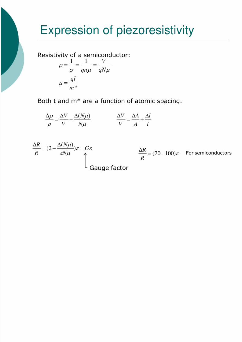
Single Crystal Silicon
Recall Ohm’s law:
z
y
x
z
y
x
i
i
i
E
E
E
345
426
561
J E
E J
Since piezoresistive coefficients depend onthe crystallographic directions:
Changes of 1 through 6 are related to the six stress components:
6
5
4
3
2
1
44
44
44
111212
121112
121211
06
05
04
03
02
01
0000000000
00000
000
000
000
/ /
/
/
/
/
For silicon, when the axesare aligned to <100>

8/3/2019 Piezoresistive Sensors 11-4-2011
http://slidepdf.com/reader/full/piezoresistive-sensors-11-4-2011 4/21
Piezoresistance Tensor,
There are three independent piezoresistive coefficients:
441211 ,,
These are influenced by the doping type,doping concentration N, and temperature.
when N and T.
Material Resistivity, Ω-cm π11, 10-11/Pa π12, 10
-11/Pa π44, , 10-11/Pa
p silicon 7.8 6.6 -1.1 138.1 n silicon
11.7
-102.2
53.4
-13.6
p germanium 1.1 -3.7 3.2 96.7 n germanium 1.5 -2.3 -3.2 -138.1

8/3/2019 Piezoresistive Sensors 11-4-2011
http://slidepdf.com/reader/full/piezoresistive-sensors-11-4-2011 5/21
Gauge factor, G
Longitudinal gauge factor, Gl,transverse gauge factor, Gt.
G is determined by multiplying the effective with E
in the direction of applied strain.
8/3/2019 Piezoresistive Sensors 11-4-2011
http://slidepdf.com/reader/full/piezoresistive-sensors-11-4-2011 6/21
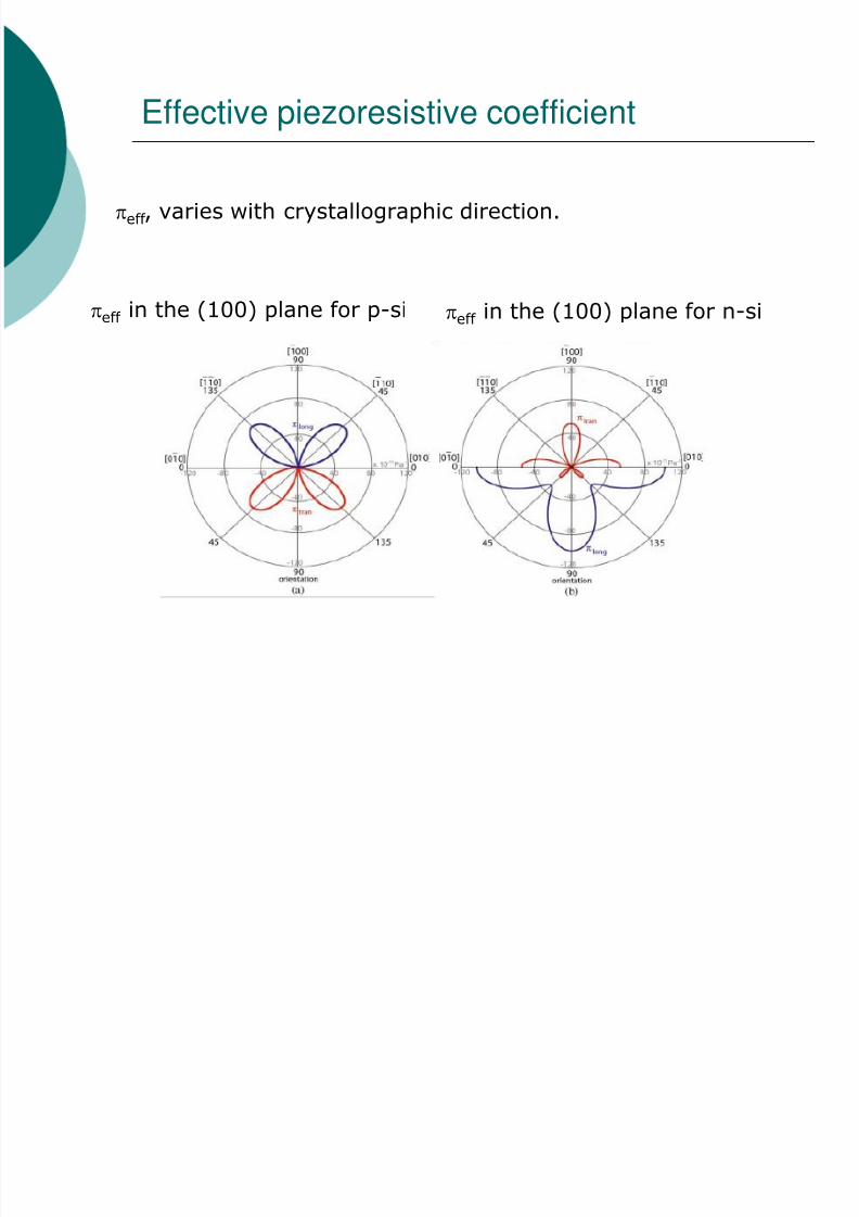
Effective piezoresistive coefficient
eff , varies with crystallographic direction.
eff in the (100) plane for p-si eff in the (100) plane for n-si

8/3/2019 Piezoresistive Sensors 11-4-2011
http://slidepdf.com/reader/full/piezoresistive-sensors-11-4-2011 7/21
Example I
A longitudinal piezoresistor is embedded on the top surfaceof a silicon cantilever near the anchored base. The cantileverPoints in the <110> direction. The piezoresistor is p-typedoped with resistivity of 7.8 cm. Young’s modulus is 168GPa.Find the longitudinal gauge factor of the piezoresistor.

8/3/2019 Piezoresistive Sensors 11-4-2011
http://slidepdf.com/reader/full/piezoresistive-sensors-11-4-2011 8/21
Polycrystalline Silicon
Advantages:• Ability to deposit on different substrates• G not dependent on the orientation of resistor• Easy doping
Disadvantages:• G is much smaller.• G is influenced by the growth and annealing conditions.
Gauge factor

8/3/2019 Piezoresistive Sensors 11-4-2011
http://slidepdf.com/reader/full/piezoresistive-sensors-11-4-2011 9/21
Stress Analysis - Cantilevers
The magnitude of stress at any point on the cross sectionis linearly proportional to the distance to the neutral axis.
The magnitude of stress reaches maximum at the top and
bottom surfaces.
The maximum strain is found to be at the surfacenear the fixed end.
EI
FLt
EI
t x M
22
)(max
F

8/3/2019 Piezoresistive Sensors 11-4-2011
http://slidepdf.com/reader/full/piezoresistive-sensors-11-4-2011 10/21
Example II
Consider a fixed-free cantilever beam made of single-crystalsilicon with its length pointing in the <100> direction. Ten points(A through J) are identified on the cantilever. The length, l,width, w, and thickness, t, are 100m, 10 m, and 6 m,respectively. If a 1mN force acts at the end of the cantilever,
what is the max? At which point does max occur?

8/3/2019 Piezoresistive Sensors 11-4-2011
http://slidepdf.com/reader/full/piezoresistive-sensors-11-4-2011 11/21
Example III
A fixed-free cantilever is made of single crystal silicon. Thelongitudinal axis points in the [100] direction. The resistorhas a longitudinal gauge factor of 50. The length, l,width, w, and thickness, t, are 200m, 20 m, and 5 m,respectively. If a force of 100 N is applied at the end of the
cantilever, what is the percentage change of resistance?

8/3/2019 Piezoresistive Sensors 11-4-2011
http://slidepdf.com/reader/full/piezoresistive-sensors-11-4-2011 12/21
Example IV
A single crystal cantilever beam has a diffused piezoresistor.The longitudinal gauge factor is 20 and the transverse gaugefactor is 10. Find the change in the resistance of the piezoresistorwhen the maximum longitudinal strain near the sensor is 1%.
F
Top view
Side view
8/3/2019 Piezoresistive Sensors 11-4-2011
http://slidepdf.com/reader/full/piezoresistive-sensors-11-4-2011 13/21
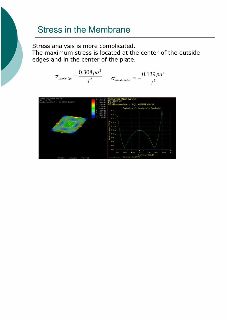
Stress in the Membrane
Stress analysis is more complicated.The maximum stress is located at the center of the outsideedges and in the center of the plate.
2
2
|max
308.0
t
pa
edge
2
2
|max
139.0
t
pacenter
8/3/2019 Piezoresistive Sensors 11-4-2011
http://slidepdf.com/reader/full/piezoresistive-sensors-11-4-2011 14/21
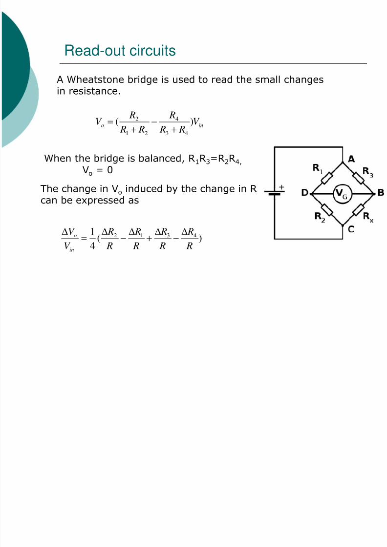
Read-out circuits
A Wheatstone bridge is used to read the small changesin resistance.
ino V R R
R
R R
RV )(
43
4
21
2
When the bridge is balanced, R1R3=R2R4,
Vo = 0
The change in Vo induced by the change in R
can be expressed as
)(4
1 4312
R
R
R
R
R
R
R
R
V
V
in
o
8/3/2019 Piezoresistive Sensors 11-4-2011
http://slidepdf.com/reader/full/piezoresistive-sensors-11-4-2011 15/21
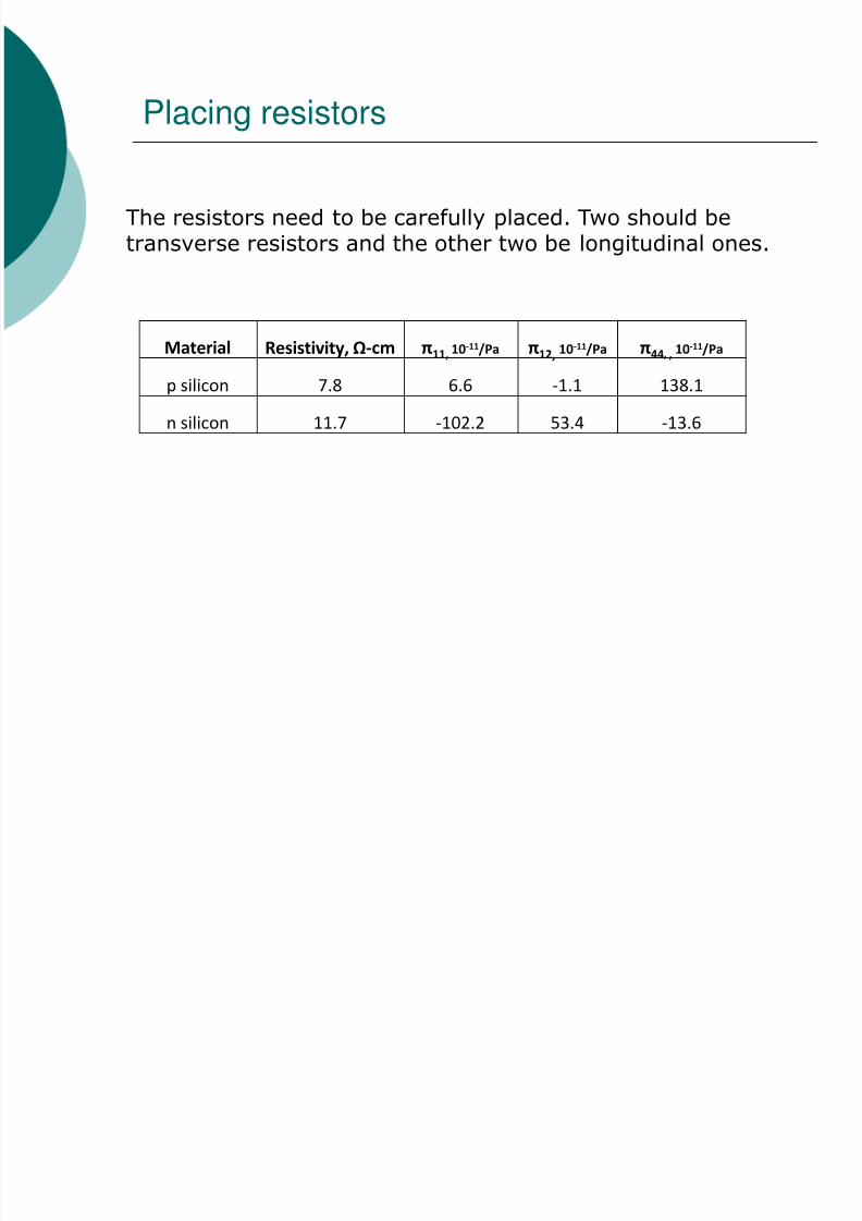
Placing resistors
The resistors need to be carefully placed. Two should betransverse resistors and the other two be longitudinal ones.
Material Resistivity, Ω-cm π11, 10-11/Pa π12, 10
-11/Pa π44, , 10-11/Pa
p silicon 7.8 6.6 -1.1 138.1 n silicon 11.7 -102.2 53.4 -13.6
8/3/2019 Piezoresistive Sensors 11-4-2011
http://slidepdf.com/reader/full/piezoresistive-sensors-11-4-2011 16/21
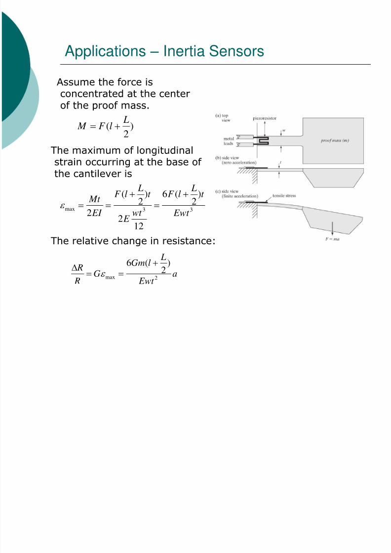
Applications – Inertia Sensors
)
2
(LlF M
Assume the force isconcentrated at the centerof the proof mass.
The maximum of longitudinalstrain occurring at the base of the cantilever is
33max
)
2
(6
122
)
2
(
2 Ewt
t LlF
wt E
t LlF
EI
Mt
The relative change in resistance:
a Ewt
LlGm
G R
R2max
)
2
(6
8/3/2019 Piezoresistive Sensors 11-4-2011
http://slidepdf.com/reader/full/piezoresistive-sensors-11-4-2011 17/21
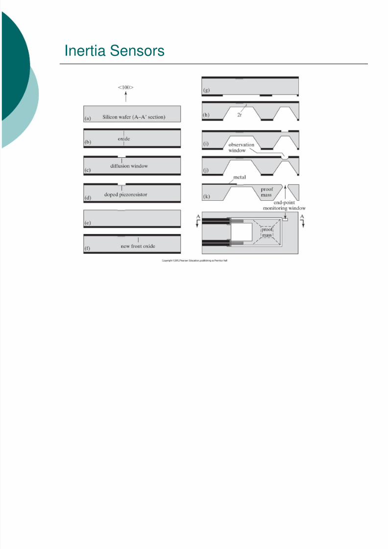
Inertia Sensors

8/3/2019 Piezoresistive Sensors 11-4-2011
http://slidepdf.com/reader/full/piezoresistive-sensors-11-4-2011 18/21
Pressure Sensors (Case Study)
The Omega PX409 pressure transducer can measure pressureranges from 0 – 6.9kPa to 0 – 34.5MPa. The DC excitationvoltage is between 5 – 10V. The output signals can eitherbe voltage (1 – 100mV, 0 – 5V) or current (4 – 20mA).
The (100) n-Si diaphragm is a square, 1.2 mm on each side and80m thick. The sensor has a 0-1MPa full scale input and0-100mV full scale output, a 10 VDC excitation.
8/3/2019 Piezoresistive Sensors 11-4-2011
http://slidepdf.com/reader/full/piezoresistive-sensors-11-4-2011 19/21
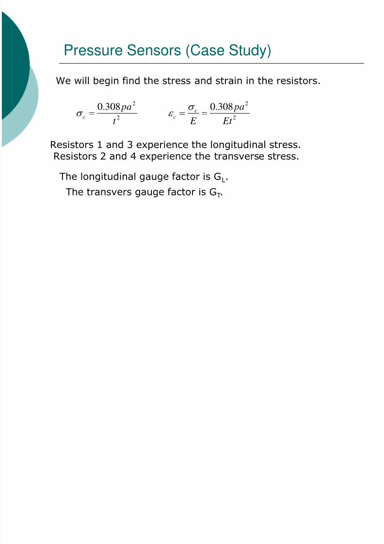
Pressure Sensors (Case Study)
We will begin find the stress and strain in the resistors.
Resistors 1 and 3 experience the longitudinal stress.Resistors 2 and 4 experience the transverse stress.
The longitudinal gauge factor is GL.
2
2308.0
t
pac
2
2308.0
Et
pa
E
cc
The transvers gauge factor is GT.

8/3/2019 Piezoresistive Sensors 11-4-2011
http://slidepdf.com/reader/full/piezoresistive-sensors-11-4-2011 20/21
Pressure Sensors (Case Study)
The output voltage change:

8/3/2019 Piezoresistive Sensors 11-4-2011
http://slidepdf.com/reader/full/piezoresistive-sensors-11-4-2011 21/21
Pressure Sensors (Case Study)
With L = -T 44 /2, Vin = 10V, and p=100kPa
mV
V o
7.95
10)1080(
)102.1(101308.0101.1382
2
1
26
23511