Embed Size (px)
Citation preview
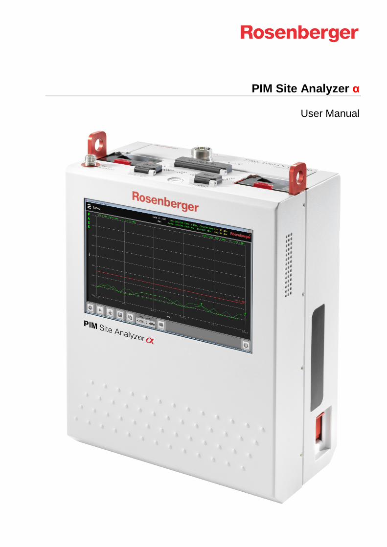
PIM Site Analyzer α
User Manual

PIM Site Analyzer α Manual
© Rosenberger 2017 - www.rosenberger.com/pia Page 2 of 54
PIM Site Analyzer α Manual
© Rosenberger 2017 - www.rosenberger.com/pia Page 3 of 54
Table of Contents
1 General Information and Safety Instructions .......................................................................................... 5
2 Package Contents .................................................................................................................................... 11
3 Product Description PIM Site Analyzer α ............................................................................................... 12
3.1 Overview .................................................................................................................................................. 12 3.2 Interface Side .......................................................................................................................................... 13 3.3 Filter ......................................................................................................................................................... 14 3.3.1 Changing the filter ................................................................................................................................ 14 4 Setting up the Device ............................................................................................................................... 15
4.1 Changing SFPs ....................................................................................................................................... 15 4.2 Battery Operation .................................................................................................................................... 15 5 Software Operation .................................................................................................................................. 16
5.1 Main Menu ............................................................................................................................................... 16 5.2 Common Settings .................................................................................................................................... 16 5.2.1 WiFi Configuration ................................................................................................................................ 16 5.2.2 Language / Color Theme ...................................................................................................................... 16 5.3 Device Info ............................................................................................................................................... 17 5.4 Measurement Screen .............................................................................................................................. 18 5.5 Report generation .................................................................................................................................... 20 5.5.1 Creating reports .................................................................................................................................... 21 5.6 Updating the PIMAnalyzer Software (Device & Tablet) .......................................................................... 23 6 Measurement Settings ............................................................................................................................. 24
6.1 Manual Mode ........................................................................................................................................... 24 6.2 2 Tone ...................................................................................................................................................... 25 6.3 Sweep ...................................................................................................................................................... 26 6.4 VSWR \ RL .............................................................................................................................................. 27 6.5 DTF .......................................................................................................................................................... 28 6.5.1 Zeroing PIM .......................................................................................................................................... 28 6.5.2 Zeroing Return Loss ............................................................................................................................. 29 6.5.3 Setting the velocity factor of the signal path ......................................................................................... 29 6.6 Isolation ................................................................................................................................................... 31 6.7 Power Sweep .......................................................................................................................................... 32 6.8 Spectrum Analyzer .................................................................................................................................. 33 7 Remote Control ......................................................................................................................................... 34
7.1 Tablet ....................................................................................................................................................... 34 8 Maintenance of the device ....................................................................................................................... 36
8.1 Handling................................................................................................................................................... 36 8.2 Cleaning................................................................................................................................................... 36 8.3 Calibration & Repair ................................................................................................................................ 36 8.4 Fundamental rules for handling fiber optics ............................................................................................ 37 9 Measurement Examples........................................................................................................................... 37
9.1 RF Measurements ................................................................................................................................... 37 9.1.1 PIM acceptance test ............................................................................................................................. 37 9.1.2 Troubleshooting a PIM problem ........................................................................................................... 37 9.1.3 PIM testing flowchart ............................................................................................................................ 38
PIM Site Analyzer α Manual
© Rosenberger 2017 - www.rosenberger.com/pia Page 4 of 54
10 Troubleshooting ..................................................................................................................................... 39
10.1 Reporting Software Problems to Rosenberger ..................................................................................... 39 10.2 How to avoid common problems ........................................................................................................... 39 11 Technical Specifications........................................................................................................................ 41
11.1 Base Unit ............................................................................................................................................... 41 11.1.1 General ............................................................................................................................................... 41 11.1.2 PIM Analyzer RF (Base Unit) ............................................................................................................. 41 11.1.3 PIM Analyzer CPRI (SW Option) ........................................................................................................ 41 11.1.4 Isolation Measurement RF ................................................................................................................. 42 11.1.5 VSWR / Return Loss RF..................................................................................................................... 42 11.1.6 Spectrum Analyzer RF ....................................................................................................................... 42 11.1.7 Environmental ..................................................................................................................................... 42 11.1.8 User Interfaces ................................................................................................................................... 43 11.2 Filter Units ............................................................................................................................................. 43 11.2.1 General ............................................................................................................................................... 43 11.2.2 Environmental ..................................................................................................................................... 43 11.2.3 IM-B-FI-700/B12+17 (LTE700 L) ........................................................................................................ 43 11.2.4 IM-B-FI-700/B13+14 (LTE700 U) ....................................................................................................... 44 11.2.5 IM-B-FI-700/B28 (APT700) ................................................................................................................ 44 11.2.6 IM-B-FI-800/B20 (DigiDiv800) ............................................................................................................ 44 11.2.7 IM-B-FI-850/B5 (AMPS850) ............................................................................................................... 44 11.2.8 IM-B-FI-900/B8 (EGSM900) ............................................................................................................... 45 11.2.9 IM-B-FI-1400/B11+21 (LTE1400) ....................................................................................................... 45 11.2.10 IM-B-FI-1800/B3 (DCS1800) ............................................................................................................ 45 11.2.11 IM-B-FI-1900/B2+4 (PCS/AWS1900) ............................................................................................... 46 11.2.12 IM-B-FI-2100/B1 (UMTS2100) ......................................................................................................... 46 11.2.13 IM-A-FI-2600/B7 (LTE II 2600) ......................................................................................................... 46 12 CE - Declaration of Conformity ............................................................................................................. 47
13 Accessories ............................................................................................................................................ 48
13.1 Power Unit ............................................................................................................................................. 48 13.2 Filter Units ............................................................................................................................................. 48 13.3 Software Option (CPRI) ......................................................................................................................... 48 13.4 Base Unit Bag ........................................................................................................................................ 49 13.5 Accessory Backpack ............................................................................................................................. 49 13.6 Other Accessories ................................................................................................................................. 50 14 Support and Sales Locations ................................................................................................................ 51
14.1 Europe, Middle East, Africa ................................................................................................................... 51 14.2 Americas ................................................................................................................................................ 51 14.3 Brazil ...................................................................................................................................................... 51 14.4 Asia Pacific ............................................................................................................................................ 52 14.5 India ....................................................................................................................................................... 52
PIM Site Analyzer α Manual
© Rosenberger 2017 - www.rosenberger.com/pia Page 5 of 54
1 General Information and Safety Instructions
Operation not according to the intended purpose, ignorance of this documentation, the use of insufficiently qualified personnel as well as unauthorized modifications exclude the liability of the manufacturer for damages resulting from this and render any warranty void.
People with cardiac stimulator must not expose the magnetic field of the batteries, the battery unit, the power unit or the charging cable.
Rosenberger makes every effort to keep the safety standards of our products up to date to offer our custom-ers the highest possible degree of safety. Our products and the accessory equipment they require are de-signed, built and tested in accordance with the safety standards that apply in each case. The compliance with these standards is monitored by our quality assurance system. The product described here has been designed, built and tested in accordance with the attached CE Certificate of Conformity and has left the manufacturers plant in a condition fully complying with safety standards. To maintain this condition and to ensure safe operation, you must observe all instructions and warnings provided in this manual. If you have any questions regarding these safety instructions please contact Rosenberger to answer them. Furthermore, it is your responsibility to use the product in an appropriate manner. This product is designed for field use and must not be used in any way that may cause personal injury or property damage. You are responsible if the product is used for any intention other than its designated purpose or in disregard of the manufacturer's instructions. The manufacturer shall assume no responsibility for such use of the product. The product is used for its designated purpose if it is used in accordance with its product documentation and within its performance limits (see data sheet, documentation, the following safety instructions). Using the product requires technical skills and a basic knowledge of the English language. It is therefore essential that only skilled and specialized staff or thoroughly trained personnel with the required skills are allowed to use the product. If personal safety gear is required for using Rosenberger PIM Site Analyzer α, this will be indi-cated at the appropriate place in the product documentation. Keep the basic safety instructions and the product documentation in a safe place and pass them on to the subsequent users. Observing the safety instructions will help prevent personal injury or damage of any kind caused by danger-ous situations. Therefore, carefully read through and adhere to the following safety instructions before and when using the product. It is also absolutely essential to observe the additional safety instructions on per-sonal safety, for example, that appear in relevant parts of the product documentation. Operating states and operating positions The product may be operated only under the operating conditions and in the positions specified by the manufacturer without the product’s ventilation being obstructed. If the manufacturer's specifications are not observed, this can result in electric shock, fire and/or serious personal injury or death. Applicable local or national safety regulations and rules for the prevention of accidents must be observed in all work performed.
• Never switch output power on (in manual mode or remote mode) without load or terminated OUT connected to the test port.
• Unless otherwise specified, the following requirements apply to this product: IP protection 2X, pollution severity 2, over voltage category 2, max. operating altitude 2000 m above sea level, max.
PIM Site Analyzer α Manual
© Rosenberger 2017 - www.rosenberger.com/pia Page 6 of 54
transport altitude 4500 m above sea level. A tolerance of: +-10 % shall apply to the nominal voltage and +- 5 % to the nominal frequency.
• Do not place the product on surfaces, vehicles, cabinets or tables that for reasons of weight or stability are unsuitable for this purpose. Always follow the manufacturer’s installation instructions when installing the product and fastening it to objects or structures (e.g. walls and shelves). An installation that is not carried out as described in the product documentation could result in personal injury or death.
• Do not cover the heat sink or ventilation openings.
• Do not place the product on heat-generating devices such as radiators or fan heaters. The ambient temperature must not exceed the maximum temperature specified in the product documentation or in the data sheet. Product overheating can cause electric shock, fire and/or serious personal injury or death.
Electrical safety If the information on electrical safety is not observed either at all to the extent necessary, electric shock, fire and/or serious personal injury or death may occur.
• Prior to switching on the product, always ensure that the nominal voltage setting on the product matches the nominal voltage of the AC supply network. If the equipment is used at different voltages, the power fuse of the product may have to be changed accordingly.
• In the case of products of safety class I with movable power cord and connector, operation is permitted only on sockets with an earthing contact and protective earth connection.
• Intentionally breaking the protective earth connection either in the feed line or in the product itself is not permitted. Doing so can result in the danger of an electric shock from the product. If extension cords or connector strips are implemented, they must be checked on a regular basis to ensure that they are safe to use.
• To disconnect the device from the AC supply network, the plug of the connecting cable is regarded as the disconnecting device. In such cases, always ensure that the power plug is easily reachable and accessible at all times (corresponding to the length of connecting cable, approx. 2 m). Functional or electronic switches are not suitable for providing disconnection from the AC supply network. If products without power switches are integrated into racks or systems, a disconnecting device must be provided at the system level.
• Never use the product if the power cable is damaged. Check the power cable on a regular basis to ensure that it is in proper operating condition. By taking appropriate safety measures and carefully laying the power cable, you can ensure that the cable will not be damaged and that no one can be hurt by, for example, tripping over the cable or suffering an electric shock.
• The product must be operated only in TN/TT mains networks fused with max. 16 A or with dedicated Rosenberger battery packs.
• Do not insert the plug into sockets that are dusty or dirty. Insert the plug firmly and all the way into the socket. Otherwise, sparks that result in fire and/or injuries may occur.
• Do not overload any sockets, extension cords or connector strips; doing so can cause fire or electric shocks.
PIM Site Analyzer α Manual
© Rosenberger 2017 - www.rosenberger.com/pia Page 7 of 54
• For measurements in circuits with voltages Vrms > 30 V, suitable measures (e.g. appropriate measuring equipment, fusing, current limiting, electrical separation, insulation) should be taken to avoid any hazards.
• Ensure that the connections with information technology equipment, e.g. PCs or other industrial computers, comply with the IEC60950-1 / EN60950-1 or IEC61010-1 / EN 61010-1 standards that apply in each case.
• Unless expressly permitted, never remove the cover or any part of the housing while the product is in operation. Doing so will expose circuits and components and can lead to injuries, fire or damage to the product.
• If a product is to be permanently installed, the connection between the PE terminal on site and the product's PE conductor must be made first before any other connection is made. The product may be installed and connected only by a licensed electrician.
• For permanently installed equipment without built—in fuses, circuit breakers or similar protective devices, the supply circuit must be fused in such a way that anyone who has access to the product, as well as the product itself, is adequately protected from injury or damage.
• Use suitable over voltage protection to ensure that no over voltage (such as that caused by a bolt of lightning) can reach the product. Otherwise, the person operating the product will be exposed to the danger of an electric shock.
• Any object that is not designed to be placed in the openings of the housing must not be used for this purpose. Doing so can cause short circuits inside the product and/or electric shocks, fire or injuries.
• Unless specified otherwise, products are not liquid-proof (see also section "Operating states and operating positions", item 1.) Therefore, the equipment must be protected against penetration by liquids. If the necessary precautions are not taken, the user may suffer electric shock or the product itself may be damaged, which can also lead to personal injury.
• Never use the product under conditions in which condensation has formed or can form in or on the product, e.g. if the product has been moved from a cold to a warm environment. Penetration by water increases the risk of electric shock.
Operation
• Operating the products requires special training and intense concentration. Make sure that persons who use the products are physically, mentally and emotionally fit enough to do so; otherwise, injuries or material damage may occur. It is the responsibility of the employer/operator to select suitable personnel for operating the products.
• Operation of the PIM Site Analyzer α can produce electromagnetic radiation. Ensure that the radiation levels do not exceed limits of national regulations. Persons with pacemakers and pregnant women are especially endangered.
• Before you move or transport the product, read and observe the section titled "Transport".
• Before you start processing the product mechanically and/or thermally, or before you take it apart, be sure to read and pay special attention to the section titled "Waste disposal", item 1.
PIM Site Analyzer α Manual
© Rosenberger 2017 - www.rosenberger.com/pia Page 8 of 54
• Should a fire occur, the product may release hazardous substances (gases, fluids, etc.) that can cause health problems. Therefore, suitable measures must be taken, e.g. protective masks and protective clothing must be worn.
Fundamental rules for handling fiber optics Laser Safety must be a concern. Refer to the module's documentation. Infrared Laser light is invisible and may be harmful for your eyes. Check fiber surfaces only with a video microscope.
• Make sure, SFP (pluggable module) is compatible with fiber type
• Do not mix fiber types in a link
• Do not touch connector ferrule
• Use protection caps whenever a connector or a module is not mated
• Do not bend or kink optical cables (R ≥ 25 mm)
• Do only use suitable cleaning equipment (Reel Cleaner, Click Cleaner)
• Check fiber surface with a video microscope before mating a connector
Repair and Service
• The product may be opened only by authorized, specially trained personnel. Before any work is performed on the product or before the product is opened, it must be disconnected from the AC supply network. Otherwise, personnel will be exposed to the risk of an electric shock.
• Adjustments, replacement of parts, maintenance and repair may be performed only by electrical experts authorized by Rosenberger. Only original parts can be used for replacing safety parts (e.g. power switches, power transformers, fuses). A safety test must always be performed after safety parts have been replaced (visual inspection, PE conductor test, insulation resistance measurement, leakage current measurement, functional test). This helps ensure the continued safety of the product.
Batteries and rechargeable batteries/cells If the information regarding batteries and rechargeable batteries/cells is not observed either at all or to the extent necessary, product users may be exposed to the risk of explosions, fire and/or serious personal injury, and, in some cases, death. Batteries and rechargeable batteries with alkaline electrolytes (e. g. lithium cells) must be handled in accordance with the EN 62133 standard.
• Cells must not be taken apart or crushed.
• Cells or batteries must not be exposed to heat or fire. Storage in direct sunlight must be avoided. Keep cells and batteries clean and dry. Clean soiled connectors using a dry, clean cloth.
• Cells or batteries must not be short-circuited. Cells or batteries must not be stored in a box or in a drawer where they can short-circuit each other, or where they can be short-circuited by other conductive materials. Cells and batteries must not be removed from their original packaging until they are ready to be used.
• Keep cells and batteries out of the hands of children. If a cell or a battery has been swallowed, seek medical aid immediately.
PIM Site Analyzer α Manual
© Rosenberger 2017 - www.rosenberger.com/pia Page 9 of 54
• Cells and batteries must not be exposed to any mechanical shocks that are stronger than permitted.
• If a cell develops a leak, the fluid must not be allowed to come into contact with the skin or eyes. If contact occurs, wash the affected area with plenty of water and seek medical aid.
• Improperly replacing or charging cells or batteries that contain alkaline electrolytes (e.g. lithium cells) can cause explosions. Replace cells or batteries only with the matching Rosenberger type (see bill of materials) in order to ensure the safety of the product.
• Cells and batteries must be recycled and kept separate from residual waste. Rechargeable batteries and normal batteries that contain lead, mercury or cadmium are hazardous waste. Observe the national regulations regarding waste disposal and recycling.
Transport
• The product may be very heavy. Therefore, the product must be handled with care. In some cases, the user may require a suitable means of lifting or moving the product (e.g. with a lift-truck) to avoid back or other physical injuries.
• The user is responsible for securely fastening the products to or on the means of transport or lifting. Observe the safety regulations of the manufacturer of the means of transport or lifting. Non-compliance can result in personal injury or material damage.
• If you use the product in a vehicle, it is the sole responsibility of the driver to drive the vehicle safely and properly. The manufacturer assumes no responsibility for accidents or collisions. Never use the product in a moving vehicle if doing so could distract the driver of the vehicle. Adequately secure the product in the vehicle to prevent injuries or other damage in the event of an accident.
• Transportation of Lithium batteries Lithium batteries as well as devices containing such batteries are classified as dangerous goods class 9 by the legislative authorities and therefore are subject to special regulations of load- securing and transportation. Regardless the type of battery, damage and contact with water or air moisture can cause heavy chemical reactions. Additionally, a short- circuit may cause a fire hazard. Employees who pack and ship Lithium batteries and devices equipped with batteries, have to be trained in compliance with the regulations: “The European Agreement Concerning the International Carriage of Dangerous Goods by Road” applies for the European traffic, and the “International Maritime Dangerous Goods Code” applies for the maritime traffic.
• Disposal of Lithium batteries You purchased a battery-operated product. The service life of the battery is quite long, but one day it needs to be disposed. Used batteries are not allowed to be dumped in the household garbage. Consumers are legally obligated to bring batteries to a suitable collection point in stores or the community. Used batteries may contain hazardous substances or heavy metals that may damage the environment and health. Batteries will be recycled; they contain important raw materials like iron, zinc, manganese or nickel. The environment and Rosenberger say Thank You.
PIM Site Analyzer α Manual
© Rosenberger 2017 - www.rosenberger.com/pia Page 10 of 54
Waste disposal
• If products or their components are mechanically and/or thermally processed in a manner that goes beyond their intended use, hazardous substances (heavy-metal dust such as lead, beryllium, nickel) may be released. For this reason, the product may only be disassembled by specially trained personnel. Improper disassembly may be hazardous to your health. National waste disposal regulations must be observed.
• If handling the product releases hazardous substances or fuels that must be disposed of in a special way, e.g. coolants or engine oils that must be replenished regularly, the safety instructions of the manufacturer of the hazardous substances or fuels and the applicable regional waste disposal regulations must be observed. Also observe the relevant safety instructions in the product documentation. The improper disposal of hazardous substances or fuels can cause health problems and lead to environmental damage.
Cleaning
• Prior to cleaning the product, disconnect it completely from the power supply (e.g. AC supply network or battery). Use a soft, non-linting cloth to clean the product. Never use chemical cleaning agents such as alcohol (except Test Port), acetone or diluents for cellulose lacquers.
• For cleaning the Test Port use pressurised air or alcohol soaked cotton swaps.
PIM Site Analyzer α Manual
© Rosenberger 2017 - www.rosenberger.com/pia Page 11 of 54
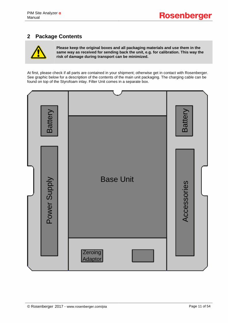
2 Package Contents
Please keep the original boxes and all packaging materials and use them in the same way as received for sending back the unit, e.g. for calibration. This way the risk of damage during transport can be minimized.
At first, please check if all parts are contained in your shipment; otherwise get in contact with Rosenberger. See graphic below for a description of the contents of the main unit packaging. The charging cable can be found on top of the Styrofoam inlay. Filter Unit comes in a separate box.
Base Unit Ac
cess
orie
s
Pow
er S
uppl
y
Zeroing Adaptor
Batte
ry
Batte
ry
PIM Site Analyzer α Manual
© Rosenberger 2017 - www.rosenberger.com/pia Page 12 of 54
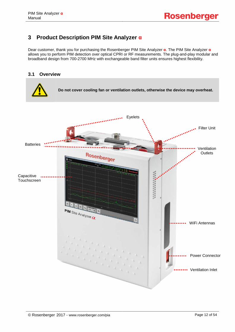
3 Product Description PIM Site Analyzer α Dear customer, thank you for purchasing the Rosenberger PIM Site Analyzer α. The PIM Site Analyzer α allows you to perform PIM detection over optical CPRI or RF measurements. The plug-and-play modular and broadband design from 700-2700 MHz with exchangeable band filter units ensures highest flexibility.
3.1 Overview
Do not cover cooling fan or ventilation outlets, otherwise the device may overheat.
Ventilation Inlet
Capacitive Touchscreen
Eyelets
Batteries
Power Connector
Filter Unit
Ventilation Outlets
WiFi Antennas
PIM Site Analyzer α Manual
© Rosenberger 2017 - www.rosenberger.com/pia Page 13 of 54
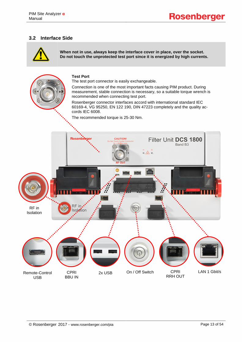
3.2 Interface Side
When not in use, always keep the interface cover in place, over the socket. Do not touch the unprotected test port since it is energized by high currents.
Remote-Control USB
2x USB LAN 1 Gbit/s CPRI BBU IN
CPRI RRH OUT
Test Port The test port connector is easily exchangeable. Connection is one of the most important facts causing PIM product. During measurement, stable connection is necessary, so a suitable torque wrench is recommended when connecting test port. Rosenberger connector interfaces accord with international standard IEC 60169-4, VG 95250, EN 122 190, DIN 47223 completely and the quality ac-cords IEC 6008. The recommended torque is 25-30 Nm.
On / Off Switch
RF in Isolation
PIM Site Analyzer α Manual
© Rosenberger 2017 - www.rosenberger.com/pia Page 14 of 54
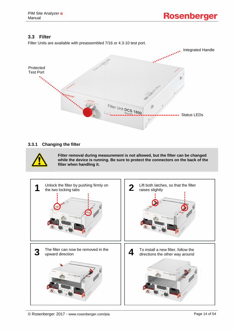
3.3 Filter Filter Units are available with preassembled 7/16 or 4.3-10 test port.
3.3.1 Changing the filter
Filter removal during measurement is not allowed, but the filter can be changed while the device is running. Be sure to protect the connectors on the back of the filter when handling it.
Integrated Handle
Protected Test Port
1 Unlock the filter by pushing firmly on the two locking tabs 2 Lift both latches, so that the filter
raises slightly
3 The filter can now be removed in the upward direction 4 To install a new filter, follow the
directions the other way around
Status LEDs
PIM Site Analyzer α Manual
© Rosenberger 2017 - www.rosenberger.com/pia Page 15 of 54
4 Setting up the Device
Always ensure the device stands stable and that the environmental conditions – listed under Chapter 1 – Section: Operating states and operating positions – are okay before starting to use the PIM Site Analyzer α.
After opening the box and unpacking the device including its accessories take the batteries and open the red protection lid on both of them. Push the batteries in the appropriate slots of the device until you feel them click into place. Before the first usage of the device the batteries should be charged fully. To do so, connect the PIM Site Analyzer α to the power supply using the included charging cable. Batteries are fully charged as soon as their LED indicators have stopped flashing. The next step is to lay the device onto the display side and insert the filter as shown in 3.3.1. After that the PIM Site Analyzer α is ready for operation. To boot the device press the Power Button, which is illuminated as long as the device is running. The boot process is finished as soon as the menu for the measurement operations is shown. You can now start your measurements. To power off the device, shortly press the Pow-er Button again and the device will shut down. The device has finished shutting down as soon as the illumi-nation of the Power Button is off.
4.1 Changing SFPs Choosing the right SFP modules depends on the site equipment. The SFP modules in the PIM Site Analyzer α have to be compatible with the Base Band Unit or else malfunction may occur. To re-move the SFP modules flap out the lever to unlock the module and pull the SFP module out. To equip a SFP module slide it in with the lever pushed down until the SFP snaps in. Mind the latching tab when connecting / disconnecting the FO cable.
4.2 Battery Operation
People with cardiac stimulator must not expose the magnetic field of the batteries, the battery unit, the power unit or the charging cable.
Always keep the red protection lid closed if batteries are removed from PIM Site Analyzer α or charger. Keep metal particles away from battery-pack and -slot, they could be attracted by the magnetic connector and cause short circuits.
The PIM Site Analyzer α runs on two battery packs. Each battery pack is dedicated to one amplifier, while the power flow to the basic system is intelligently controlled to keep the device running even if one battery fails. So, if no measurement is running one battery at a time can be changed without shutting down the de-vice. Battery charging will start immediately after connecting the charger which can be seen by the flashing LED indicator. For lifetime and safety reasons charging won’t start if battery temperature is too high or too low. Please plug in battery again when it reached a normal temperature. Fully discharged batteries (below approx. 5%) will run through a pre-charge cycle to lengthen their lifetime for up to 45 min prior to the fast charge. During that time their LED indicators will not flash and the battery may not be recognized in the status menu.
PIM Site Analyzer α Manual
© Rosenberger 2017 - www.rosenberger.com/pia Page 16 of 54
5 Software Operation
The PIM Site Analyzer α runs on Microsoft Windows 7. If you install additional soft-ware or change system settings, Rosenberger can’t guarantee a flawless operation anymore. Please backup your data (e.g. reports) on a regular basis.
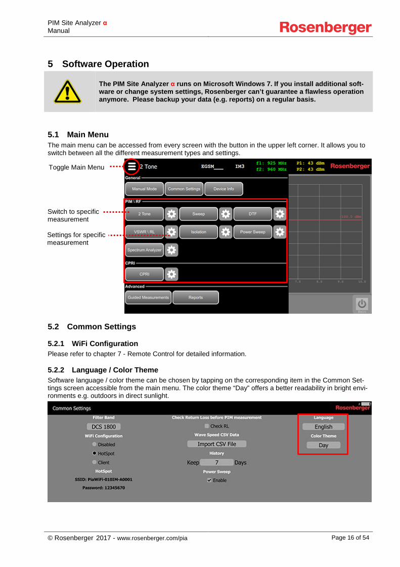
5.1 Main Menu The main menu can be accessed from every screen with the button in the upper left corner. It allows you to switch between all the different measurement types and settings.
5.2 Common Settings
5.2.1 WiFi Configuration Please refer to chapter 7 - Remote Control for detailed information.
5.2.2 Language / Color Theme Software language / color theme can be chosen by tapping on the corresponding item in the Common Set-tings screen accessible from the main menu. The color theme “Day” offers a better readability in bright envi-ronments e.g. outdoors in direct sunlight.
Switch to specific measurement
Toggle Main Menu
Settings for specific measurement
PIM Site Analyzer α Manual
© Rosenberger 2017 - www.rosenberger.com/pia Page 17 of 54
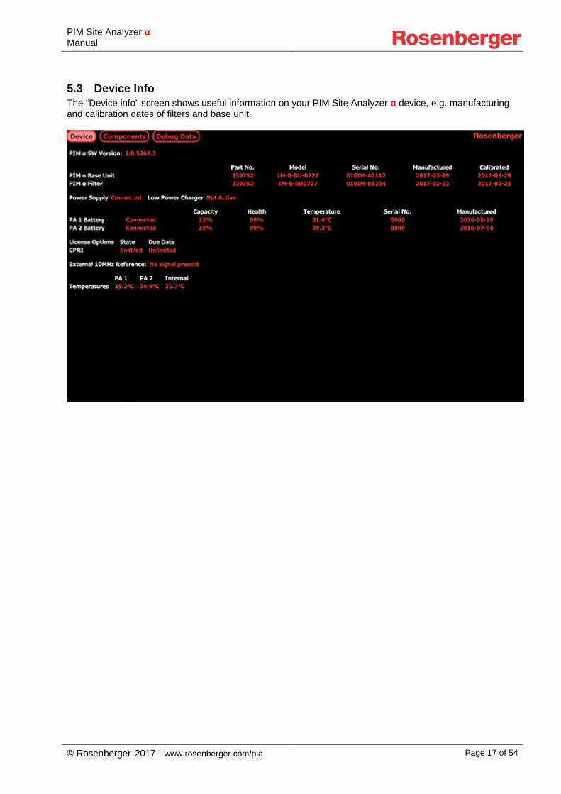
5.3 Device Info The “Device info” screen shows useful information on your PIM Site Analyzer α device, e.g. manufacturing and calibration dates of filters and base unit.
PIM Site Analyzer α Manual
© Rosenberger 2017 - www.rosenberger.com/pia Page 18 of 54
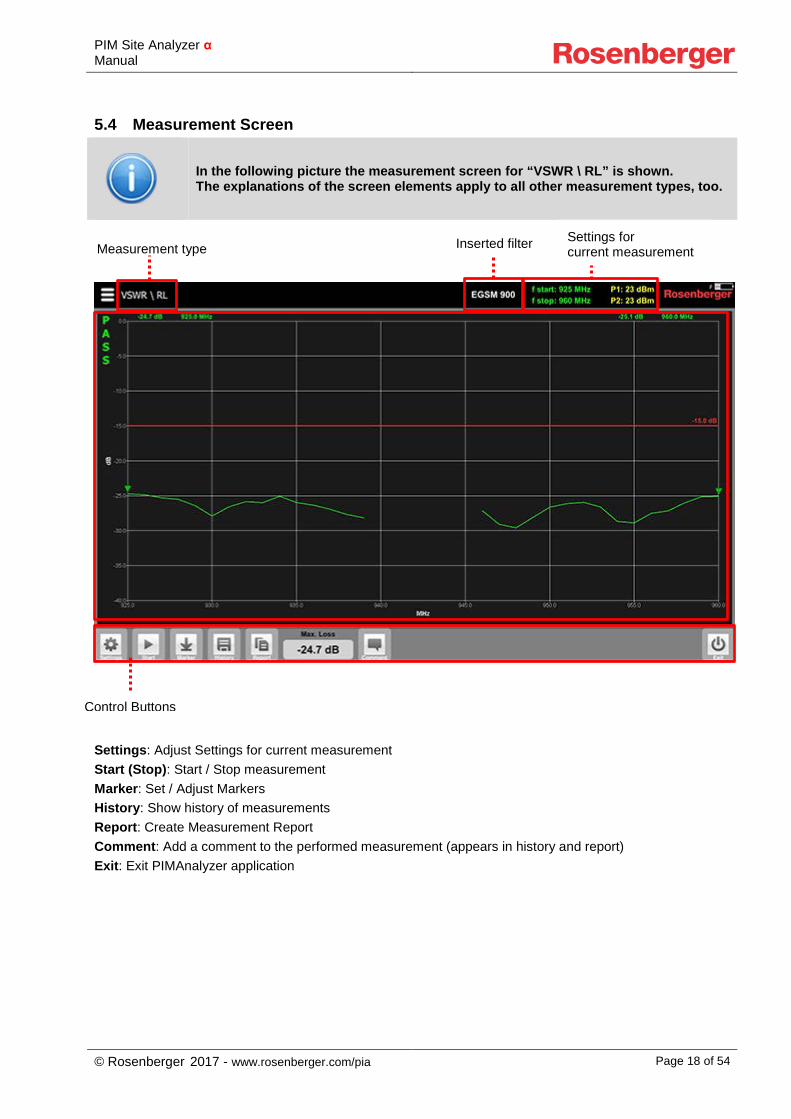
5.4 Measurement Screen
In the following picture the measurement screen for “VSWR \ RL” is shown. The explanations of the screen elements apply to all other measurement types, too.
Settings: Adjust Settings for current measurement Start (Stop): Start / Stop measurement Marker: Set / Adjust Markers History: Show history of measurements Report: Create Measurement Report Comment: Add a comment to the performed measurement (appears in history and report) Exit: Exit PIMAnalyzer application
Inserted filter Settings for current measurement
Control Buttons
Measurement type
PIM Site Analyzer α Manual
© Rosenberger 2017 - www.rosenberger.com/pia Page 19 of 54
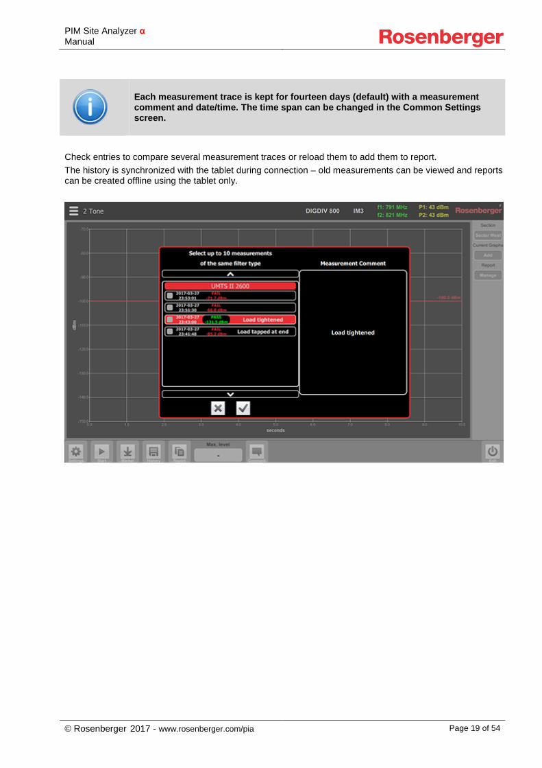
Each measurement trace is kept for fourteen days (default) with a measurement comment and date/time. The time span can be changed in the Common Settings screen.
Check entries to compare several measurement traces or reload them to add them to report. The history is synchronized with the tablet during connection – old measurements can be viewed and reports can be created offline using the tablet only.
PIM Site Analyzer α Manual
© Rosenberger 2017 - www.rosenberger.com/pia Page 20 of 54
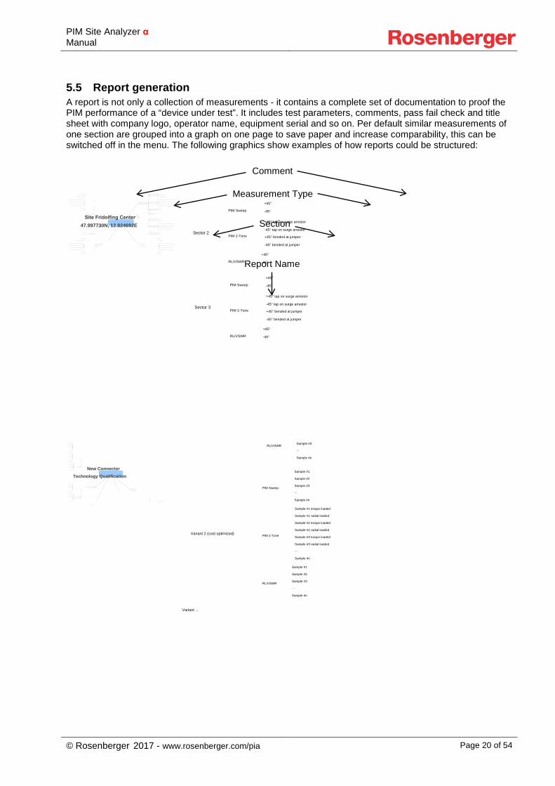
5.5 Report generation A report is not only a collection of measurements - it contains a complete set of documentation to proof the PIM performance of a “device under test”. It includes test parameters, comments, pass fail check and title sheet with company logo, operator name, equipment serial and so on. Per default similar measurements of one section are grouped into a graph on one page to save paper and increase comparability, this can be switched off in the menu. The following graphics show examples of how reports could be structured:
Site Fridolfing Center47.997730N, 12.824692E
Sector 2
PIM Sweep
+45°
-45°
PIM 2-Tone
+45° tap on surge arrestor
-45° tap on surge arrestor
+45° bended at jumper
-45° bended at jumper
RL/VSWR
+45°
-45°
Sector 3
PIM Sweep
+45°
-45°
PIM 2-Tone
+45° tap on surge arrestor
-45° tap on surge arrestor
+45° bended at jumper
-45° bended at jumper
RL/VSWR
+45°
-45°
New Connector Technology Qualification
RL/VSWR
p
Sample #3
...
Sample #n
Variant 2 (cost optimized)
PIM Sweep
Sample #1
Sample #2
Sample #3
...
Sample #n
PIM 2-Tone
Sample #1 torque loaded
Sample #1 radial loaded
Sample #2 torque loaded
Sample #2 radial loaded
Sample #3 torque loaded
Sample #3 radial loaded
...
Sample #n
RL/VSWR
Sample #1
Sample #2
Sample #3
...
Sample #n
Variant ...
Report Name
Section
Measurement Type
Comment
PIM Site Analyzer α Manual
© Rosenberger 2017 - www.rosenberger.com/pia Page 21 of 54
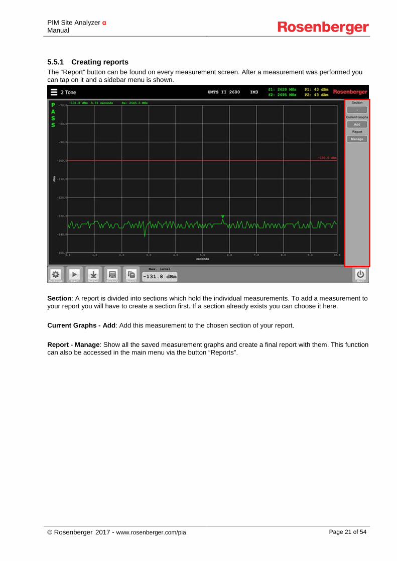
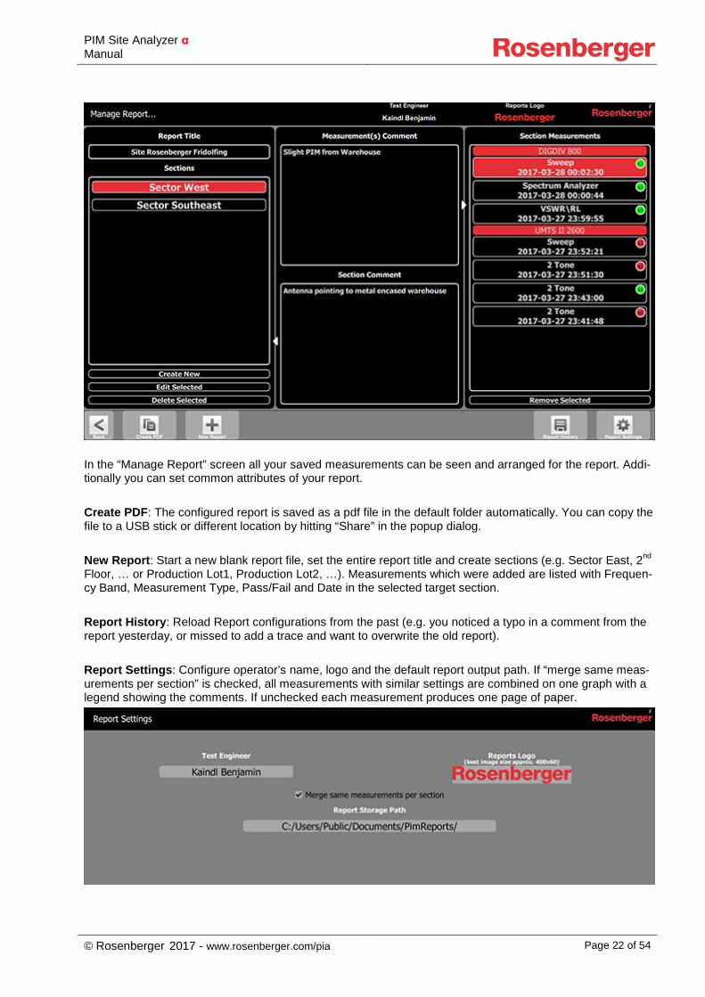
5.5.1 Creating reports The “Report” button can be found on every measurement screen. After a measurement was performed you can tap on it and a sidebar menu is shown.
Section: A report is divided into sections which hold the individual measurements. To add a measurement to your report you will have to create a section first. If a section already exists you can choose it here. Current Graphs - Add: Add this measurement to the chosen section of your report. Report - Manage: Show all the saved measurement graphs and create a final report with them. This function can also be accessed in the main menu via the button “Reports”.
PIM Site Analyzer α Manual
© Rosenberger 2017 - www.rosenberger.com/pia Page 22 of 54
In the “Manage Report” screen all your saved measurements can be seen and arranged for the report. Addi-tionally you can set common attributes of your report. Create PDF: The configured report is saved as a pdf file in the default folder automatically. You can copy the file to a USB stick or different location by hitting “Share” in the popup dialog. New Report: Start a new blank report file, set the entire report title and create sections (e.g. Sector East, 2nd Floor, … or Production Lot1, Production Lot2, …). Measurements which were added are listed with Frequen-cy Band, Measurement Type, Pass/Fail and Date in the selected target section. Report History: Reload Report configurations from the past (e.g. you noticed a typo in a comment from the report yesterday, or missed to add a trace and want to overwrite the old report). Report Settings: Configure operator’s name, logo and the default report output path. If “merge same meas-urements per section” is checked, all measurements with similar settings are combined on one graph with a legend showing the comments. If unchecked each measurement produces one page of paper.
PIM Site Analyzer α Manual
© Rosenberger 2017 - www.rosenberger.com/pia Page 23 of 54
5.6 Updating the PIMAnalyzer Software (Device & Tablet) To benefit from the latest the latest improvements and to ensure a reliable and secure operation of the PIM Site Analyzer α it is important to keep the software up to date. The following steps describe how to install software updates of the PIMAnalyzer software:
1. Go to http://www.rosenberger.com/pia to download the latest software version 2. Close PIMAnalyzer application and connected Tablet application 3. Run the Setup file PimAlphaSetup-x.x.exe on the PIMAnalyzer’s Windows system, typically from an
USB stick 4. Start the PIMAnalyzer application, and check the software version under Menu -> Device Info 5. Run the .apk file on the tablet. Connect the tablet to a PC via USB, choose “File Transfer” on the
Tablet and then copy the apk file to the tablet’s file system. Run the apk file on the tablet from “File Commander”
6. Start the Tablet application, and check the software version under Menu -> Device Info -> Components -> Tablet, SW version
PIM Site Analyzer α Manual
© Rosenberger 2017 - www.rosenberger.com/pia Page 24 of 54
6 Measurement Settings
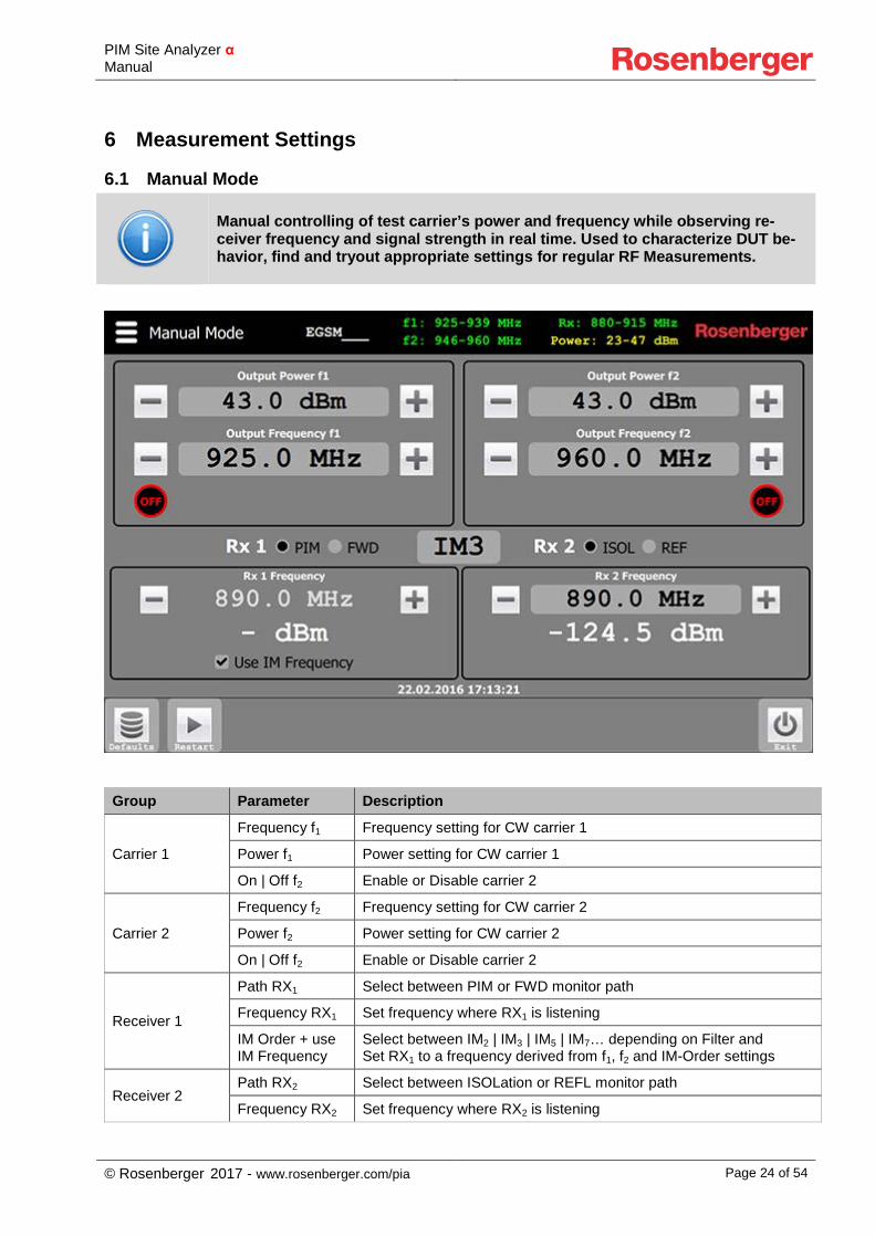
6.1 Manual Mode
Manual controlling of test carrier’s power and frequency while observing re-ceiver frequency and signal strength in real time. Used to characterize DUT be-havior, find and tryout appropriate settings for regular RF Measurements.
Group Parameter Description
Carrier 1
Frequency f1 Frequency setting for CW carrier 1
Power f1 Power setting for CW carrier 1
On | Off f2 Enable or Disable carrier 2
Carrier 2
Frequency f2 Frequency setting for CW carrier 2
Power f2 Power setting for CW carrier 2
On | Off f2 Enable or Disable carrier 2
Receiver 1
Path RX1 Select between PIM or FWD monitor path
Frequency RX1 Set frequency where RX1 is listening
IM Order + use IM Frequency
Select between IM2 | IM3 | IM5 | IM7… depending on Filter and Set RX1 to a frequency derived from f1, f2 and IM-Order settings
Receiver 2 Path RX2 Select between ISOLation or REFL monitor path
Frequency RX2 Set frequency where RX2 is listening
PIM Site Analyzer α Manual
© Rosenberger 2017 - www.rosenberger.com/pia Page 25 of 54
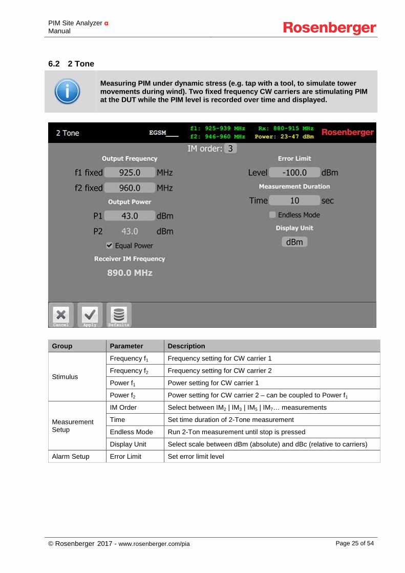
6.2 2 Tone
Measuring PIM under dynamic stress (e.g. tap with a tool, to simulate tower movements during wind). Two fixed frequency CW carriers are stimulating PIM at the DUT while the PIM level is recorded over time and displayed.
Group Parameter Description
Stimulus
Frequency f1 Frequency setting for CW carrier 1
Frequency f2 Frequency setting for CW carrier 2
Power f1 Power setting for CW carrier 1
Power f2 Power setting for CW carrier 2 – can be coupled to Power f1
Measurement Setup
IM Order Select between IM2 | IM3 | IM5 | IM7… measurements
Time Set time duration of 2-Tone measurement
Endless Mode Run 2-Ton measurement until stop is pressed
Display Unit Select scale between dBm (absolute) and dBc (relative to carriers)
Alarm Setup Error Limit Set error limit level
PIM Site Analyzer α Manual
© Rosenberger 2017 - www.rosenberger.com/pia Page 26 of 54
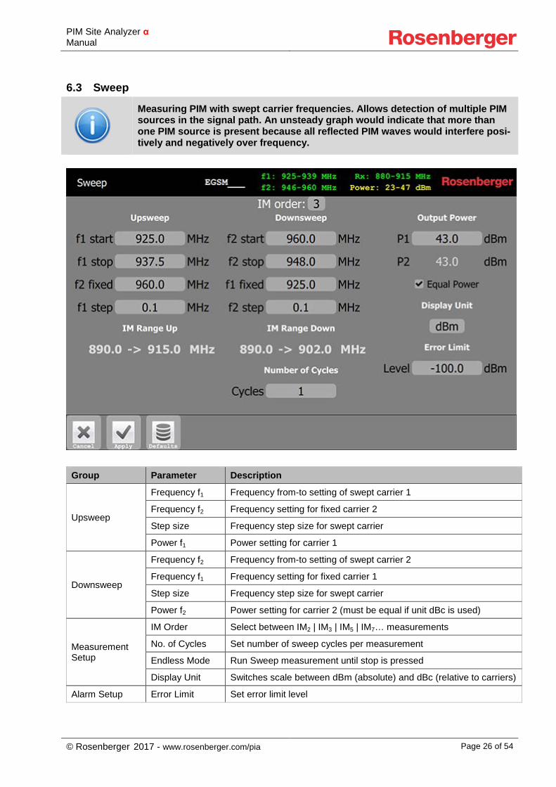
6.3 Sweep
Measuring PIM with swept carrier frequencies. Allows detection of multiple PIM sources in the signal path. An unsteady graph would indicate that more than one PIM source is present because all reflected PIM waves would interfere posi-tively and negatively over frequency.
Group Parameter Description
Upsweep
Frequency f1 Frequency from-to setting of swept carrier 1
Frequency f2 Frequency setting for fixed carrier 2
Step size Frequency step size for swept carrier
Power f1 Power setting for carrier 1
Downsweep
Frequency f2 Frequency from-to setting of swept carrier 2
Frequency f1 Frequency setting for fixed carrier 1
Step size Frequency step size for swept carrier
Power f2 Power setting for carrier 2 (must be equal if unit dBc is used)
Measurement Setup
IM Order Select between IM2 | IM3 | IM5 | IM7… measurements
No. of Cycles Set number of sweep cycles per measurement
Endless Mode Run Sweep measurement until stop is pressed
Display Unit Switches scale between dBm (absolute) and dBc (relative to carriers)
Alarm Setup Error Limit Set error limit level
PIM Site Analyzer α Manual
© Rosenberger 2017 - www.rosenberger.com/pia Page 27 of 54
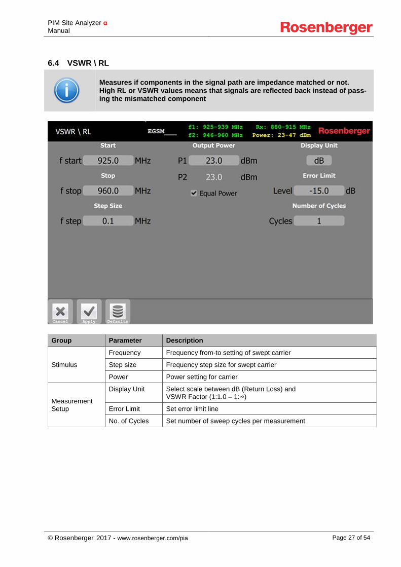
6.4 VSWR \ RL
Measures if components in the signal path are impedance matched or not. High RL or VSWR values means that signals are reflected back instead of pass-ing the mismatched component
Group Parameter Description
Stimulus
Frequency Frequency from-to setting of swept carrier
Step size Frequency step size for swept carrier
Power Power setting for carrier
Measurement Setup
Display Unit Select scale between dB (Return Loss) and VSWR Factor (1:1.0 – 1:∞)
Error Limit Set error limit line
No. of Cycles Set number of sweep cycles per measurement
PIM Site Analyzer α Manual
© Rosenberger 2017 - www.rosenberger.com/pia Page 28 of 54
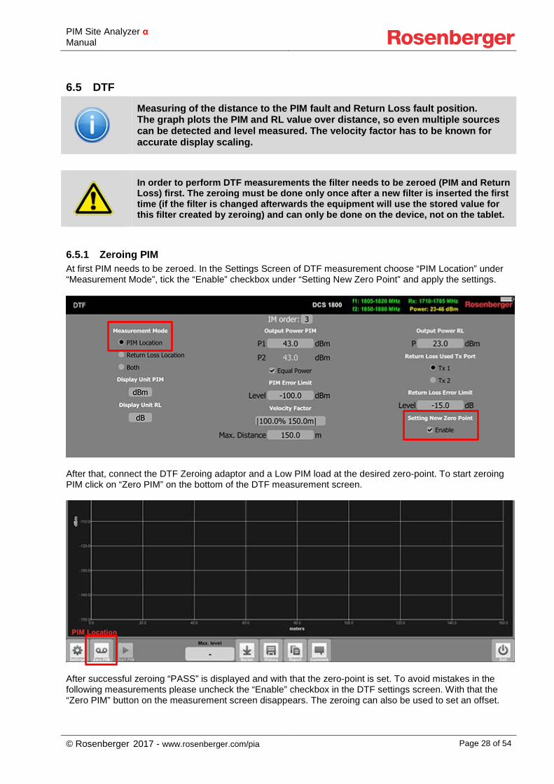
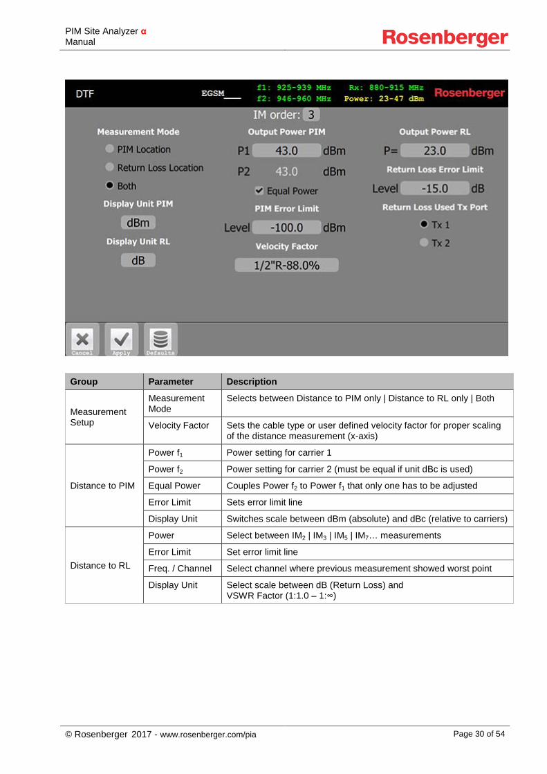
6.5 DTF
Measuring of the distance to the PIM fault and Return Loss fault position. The graph plots the PIM and RL value over distance, so even multiple sources can be detected and level measured. The velocity factor has to be known for accurate display scaling.
In order to perform DTF measurements the filter needs to be zeroed (PIM and Return Loss) first. The zeroing must be done only once after a new filter is inserted the first time (if the filter is changed afterwards the equipment will use the stored value for this filter created by zeroing) and can only be done on the device, not on the tablet.
6.5.1 Zeroing PIM At first PIM needs to be zeroed. In the Settings Screen of DTF measurement choose “PIM Location” under “Measurement Mode”, tick the “Enable” checkbox under “Setting New Zero Point” and apply the settings.
After that, connect the DTF Zeroing adaptor and a Low PIM load at the desired zero-point. To start zeroing PIM click on “Zero PIM” on the bottom of the DTF measurement screen.
After successful zeroing “PASS” is displayed and with that the zero-point is set. To avoid mistakes in the following measurements please uncheck the “Enable” checkbox in the DTF settings screen. With that the “Zero PIM” button on the measurement screen disappears. The zeroing can also be used to set an offset.
PIM Site Analyzer α Manual
© Rosenberger 2017 - www.rosenberger.com/pia Page 29 of 54
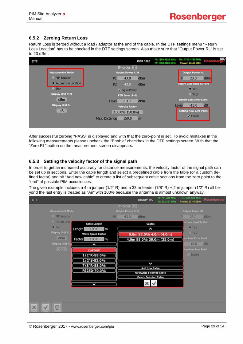
6.5.2 Zeroing Return Loss Return Loss is zeroed without a load / adaptor at the end of the cable. In the DTF settings menu “Return Loss Location” has to be checked in the DTF settings screen. Also make sure that “Output Power RL” is set to 23 dBm.
After successful zeroing “PASS” is displayed and with that the zero-point is set. To avoid mistakes in the following measurements please uncheck the “Enable” checkbox in the DTF settings screen. With that the “Zero RL” button on the measurement screen disappears.
6.5.3 Setting the velocity factor of the signal path In order to get an increased accuracy for distance measurements, the velocity factor of the signal path can be set up in sections. Enter the cable length and select a predefined cable from the table (or a custom de-fined factor) and hit “Add new cable” to create a list of subsequent cable sections from the zero point to the “end” of possible PIM occurrences. The given example includes a 4 m jumper (1/2” R) and a 33 m feeder (7/8” R) + 2 m jumper (1/2” R) all be-yond the last entry is treated as “Air” with 100% because the antenna is almost unknown anyway.
PIM Site Analyzer α Manual
© Rosenberger 2017 - www.rosenberger.com/pia Page 30 of 54
Group Parameter Description
Measurement Setup
Measurement Mode
Selects between Distance to PIM only | Distance to RL only | Both
Velocity Factor Sets the cable type or user defined velocity factor for proper scaling of the distance measurement (x-axis)
Distance to PIM
Power f1 Power setting for carrier 1
Power f2 Power setting for carrier 2 (must be equal if unit dBc is used)
Equal Power Couples Power f2 to Power f1 that only one has to be adjusted
Error Limit Sets error limit line
Display Unit Switches scale between dBm (absolute) and dBc (relative to carriers)
Distance to RL
Power Select between IM2 | IM3 | IM5 | IM7… measurements
Error Limit Set error limit line
Freq. / Channel Select channel where previous measurement showed worst point
Display Unit Select scale between dB (Return Loss) and VSWR Factor (1:1.0 – 1:∞)
PIM Site Analyzer α Manual
© Rosenberger 2017 - www.rosenberger.com/pia Page 31 of 54
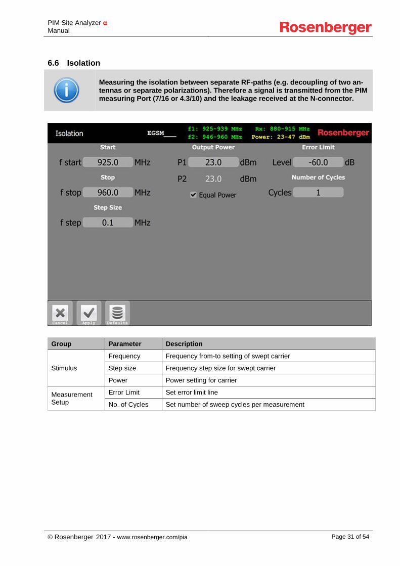
6.6 Isolation
Measuring the isolation between separate RF-paths (e.g. decoupling of two an-tennas or separate polarizations). Therefore a signal is transmitted from the PIM measuring Port (7/16 or 4.3/10) and the leakage received at the N-connector.
Group Parameter Description
Stimulus
Frequency Frequency from-to setting of swept carrier
Step size Frequency step size for swept carrier
Power Power setting for carrier
Measurement Setup
Error Limit Set error limit line
No. of Cycles Set number of sweep cycles per measurement
PIM Site Analyzer α Manual
© Rosenberger 2017 - www.rosenberger.com/pia Page 32 of 54
6.7 Power Sweep
Measuring PIM as a function of power to the DUT. Because PIM is an extremely nonlinear effect of many causes, it is hard to predict at which power PIM starts to rise. PIM sources or measurement headroom can be identified in this manner.
Group Parameter Description
Sweep Setup
Frequency f1 Frequency setting for CW carrier 1
Frequency f2 Frequency setting for CW carrier 2
Frequency fIM Shows resulting IM Frequency from f1 f2 setting
Power Power sweep from-to setting of both carriers
Step size Power increase per step for power sweep
Measurement Setup
IM Order Select between IM2 | IM3 | IM5 | IM7… measurements
No. of Cycles Set number of sweep cycles per measurement
Display Unit Switches scale between dBm (absolute) and dBc (relative to carriers)
Alarm Setup Error Limit Set error limit level
PIM Site Analyzer α Manual
© Rosenberger 2017 - www.rosenberger.com/pia Page 33 of 54
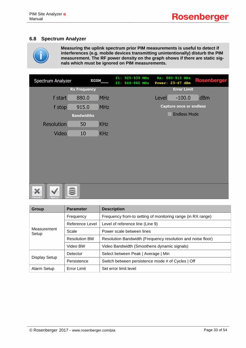
6.8 Spectrum Analyzer
Measuring the uplink spectrum prior PIM measurements is useful to detect if interferences (e.g. mobile devices transmitting unintentionally) disturb the PIM measurement. The RF power density on the graph shows if there are static sig-nals which must be ignored on PIM measurements.
Group Parameter Description
Measurement Setup
Frequency Frequency from-to setting of monitoring range (in RX range)
Reference Level Level of reference line (Line 9)
Scale Power scale between lines
Resolution BW Resolution Bandwidth (Frequency resolution and noise floor)
Video BW Video Bandwidth (Smoothens dynamic signals)
Display Setup Detector Select between Peak | Average | Min
Persistence Switch between persistence mode # of Cycles | Off
Alarm Setup Error Limit Set error limit level
PIM Site Analyzer α Manual
© Rosenberger 2017 - www.rosenberger.com/pia Page 34 of 54
7 Remote Control
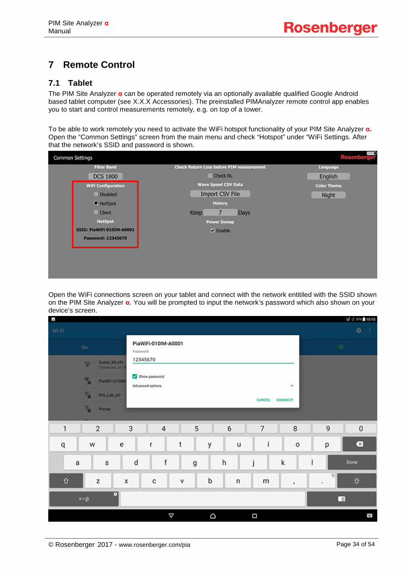
7.1 Tablet The PIM Site Analyzer α can be operated remotely via an optionally available qualified Google Android based tablet computer (see X.X.X Accessories). The preinstalled PIMAnalyzer remote control app enables you to start and control measurements remotely, e.g. on top of a tower. To be able to work remotely you need to activate the WiFi hotspot functionality of your PIM Site Analyzer α. Open the “Common Settings” screen from the main menu and check “Hotspot” under “WiFi Settings. After that the network’s SSID and password is shown.
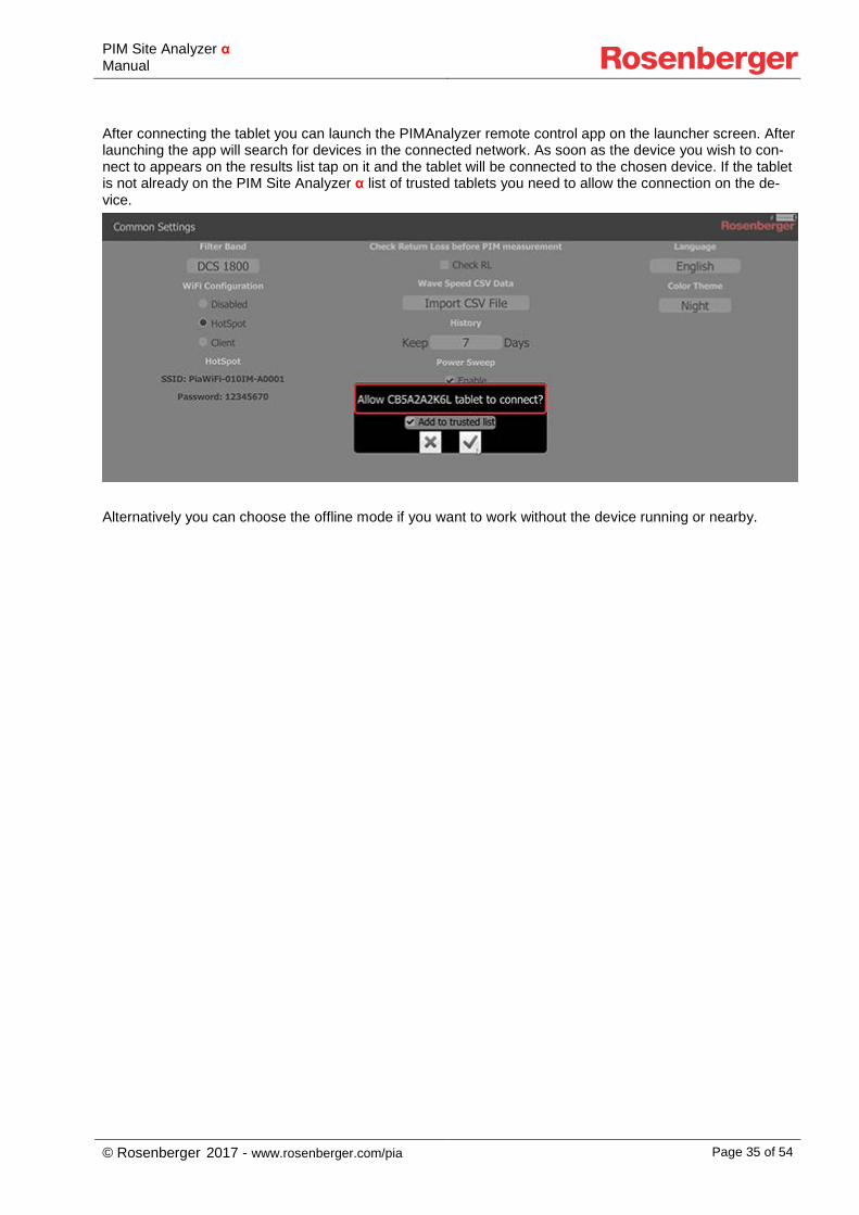
Open the WiFi connections screen on your tablet and connect with the network entitiled with the SSID shown on the PIM Site Analyzer α. You will be prompted to input the network’s password which also shown on your device’s screen.
PIM Site Analyzer α Manual
© Rosenberger 2017 - www.rosenberger.com/pia Page 35 of 54
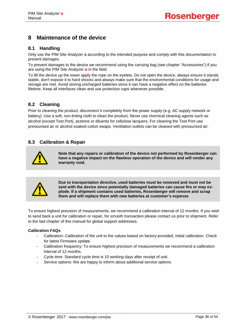
After connecting the tablet you can launch the PIMAnalyzer remote control app on the launcher screen. After launching the app will search for devices in the connected network. As soon as the device you wish to con-nect to appears on the results list tap on it and the tablet will be connected to the chosen device. If the tablet is not already on the PIM Site Analyzer α list of trusted tablets you need to allow the connection on the de-vice.
Alternatively you can choose the offline mode if you want to work without the device running or nearby.
PIM Site Analyzer α Manual
© Rosenberger 2017 - www.rosenberger.com/pia Page 36 of 54
8 Maintenance of the device
8.1 Handling Only use the PIM Site Analyzer α according to the intended purpose and comply with this documentation to prevent damages. To prevent damages to the device we recommend using the carrying bag (see chapter “Accessories”) if you are using the PIM Site Analyzer α in the field. To lift the device up the tower apply the rope on the eyelets. Do not open the device, always ensure it stands stable, don’t expose it to hard shocks and always make sure that the environmental conditions for usage and storage are met. Avoid storing uncharged batteries since it can have a negative effect on the batteries lifetime. Keep all interfaces clean and use protection caps whenever possible.
8.2 Cleaning Prior to cleaning the product, disconnect it completely from the power supply (e.g. AC supply network or battery). Use a soft, non-linting cloth to clean the product. Never use chemical cleaning agents such as alcohol (except Test Port), acetone or diluents for cellulose lacquers. For cleaning the Test Port use pressurised air or alcohol soaked cotton swaps. Ventilation outlets can be cleaned with pressurized air.
8.3 Calibration & Repair
Note that any repairs or calibration of the device not performed by Rosenberger can have a negative impact on the flawless operation of the device and will render any warranty void.
Due to transportation directive, used batteries must be removed and must not be sent with the device since potentially damaged batteries can cause fire or may ex-plode. If a shipment contains used batteries, Rosenberger will remove and scrap them and will replace them with new batteries at customer’s expense.
To ensure highest precision of measurements, we recommend a calibration interval of 12 months. If you wish to send back a unit for calibration or repair, for smooth transaction please contact us prior to shipment. Refer to the last chapter of this manual for global support addresses.
Calibration FAQs - Calibration: Calibration of the unit to the values based on factory-provided, initial calibration. Check
for latest Firmware update. - Calibration frequency: To ensure highest precision of measurements we recommend a calibration
interval of 12 months. - Cycle time: Standard cycle time is 10 working days after receipt of unit. - Service options: We are happy to inform about additional service options
PIM Site Analyzer α Manual
© Rosenberger 2017 - www.rosenberger.com/pia Page 37 of 54
8.4 Fundamental rules for handling fiber optics Laser Safety must be a concern. Refer to the module's documentation. Infrared Laser light is invisible and may be harmful for your eyes. Check fiber surfaces only with a video microscope.
• Make sure, SFP (pluggable module) is compatible with fiber type
• Do not mix fiber types in a link
• Do not touch connector ferrule
• Use protection caps whenever a connector or a module is not mated
• Do not bend or kink optical cables (R ≥ 25 mm)
• Only use suitable cleaning equipment (Reel Cleaner, Click Cleaner)
• Check fiber surface with a video microscope before mating a connector
9 Measurement Examples
The following instructions are only recommendations. The actual requirements of PIM testing and verification can vary depending on the site operators specifications.
9.1 RF Measurements
Common Checklist for fixing PIM: 1. Tighten RF-Connectors using appropriate torque 2. Cleaning connector interfaces with alcohol, Q-Tip and compressed air 3. Replace components (e.g. feeder connector)
9.1.1 PIM acceptance test 1. Disconnect cable from base station and connect it to the test port of the device 2. Disconnect the antenna and terminate the connection with a Low PIM Load (60Z150-020) 3. Do a 2 Tone measurement, during which you tap on every cable junction to simulate mechanical
stress (e.g. wind) 4. Do a Sweep measurement over the widest possible frequency range 5. If PIM is not within specified limit refer to 9.1.2 6. IF PIM is within specified limit, create test report and save it
9.1.2 Troubleshooting a PIM problem 1. Disconnect cable from base station and connect it to the test port of the device 2. Disconnect the antenna and terminate the connection with a Low PIM Load (60Z150-020) 3. Use the Spectrum Analyzer to evaluate interference signals from external sources (e.g. mobile
phones or other operator creating strong PIM signals) and eliminate them if present 4. Do a Sweep measurement to evaluate if the PIM depends on frequency
1. If no PIM is present do a 2 Tone measurement with a tap test
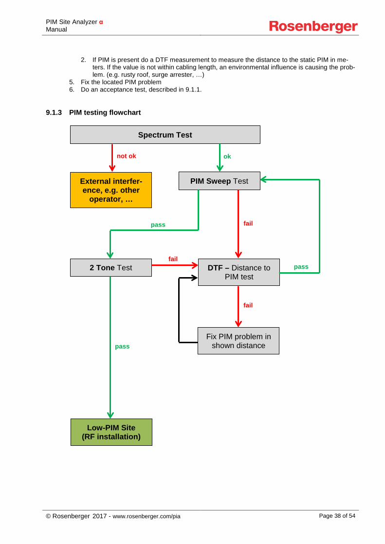
PIM Site Analyzer α Manual
© Rosenberger 2017 - www.rosenberger.com/pia Page 38 of 54
2. If PIM is present do a DTF measurement to measure the distance to the static PIM in me-ters. If the value is not within cabling length, an environmental influence is causing the prob-lem. (e.g. rusty roof, surge arrester, …)
5. Fix the located PIM problem 6. Do an acceptance test, described in 9.1.1.
9.1.3 PIM testing flowchart Spectrum Test
PIM Sweep Test External interfer-ence, e.g. other
operator, …
2 Tone Test DTF – Distance to PIM test
Low-PIM Site (RF installation)
pass fail
pass
fail
ok not ok
Fix PIM problem in shown distance
pass
fail
PIM Site Analyzer α Manual
© Rosenberger 2017 - www.rosenberger.com/pia Page 39 of 54
10 Troubleshooting
10.1 Reporting Software Problems to Rosenberger In case of any problems related to the use of PIM Analyzer Software, in order to make sure we can analyze the problem quickly and provide an effective solution, please follow these steps to provide related debug data to your Rosenberger sales/service partner: If the issue is reproducible without using the tablet:
1. Make sure that the latest software is installed 2. Restart PimAnalyzer Software
a. If the problem is that the PimAnalyzer software is not starting, execute C:\Software\PimAnalyzer\PiaDebugData.exe instead
3. Reproduce the issue 4. Go to Device Info -> Debug Data, and generate a debug data zip file. 5. Send the file to [email protected] along with the exact steps describing what has been
done with the device If the issue is reproducible only in case of using the tablet:
1. Make sure that the latest software (both on device and on tablet) is installed 2. Restart PimAnalyzer Software 3. Restart Tablet App 4. Reproduce the issue 5. On the Tablet: Go to Device Info -> Debug Data, and generate a debug data zip file 6. Close Tablet App 7. On the Device: Go to Device Info -> Debug Data, and generate a debug data zip file 8. Send the files to [email protected] along with the exact steps describing what has been
done with the device and the tablet
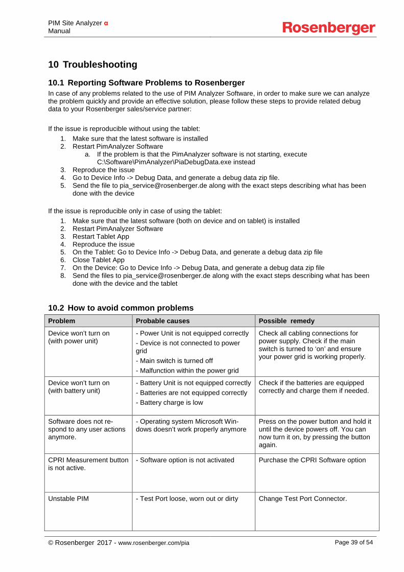
10.2 How to avoid common problems Problem Probable causes Possible remedy
Device won’t turn on (with power unit)
- Power Unit is not equipped correctly - Device is not connected to power grid - Main switch is turned off - Malfunction within the power grid
Check all cabling connections for power supply. Check if the main switch is turned to ‘on’ and ensure your power grid is working properly.
Device won’t turn on (with battery unit)
- Battery Unit is not equipped correctly - Batteries are not equipped correctly - Battery charge is low
Check if the batteries are equipped correctly and charge them if needed.
Software does not re-spond to any user actions anymore.
- Operating system Microsoft Win-dows doesn’t work properly anymore
Press on the power button and hold it until the device powers off. You can now turn it on, by pressing the button again.
CPRI Measurement button is not active.
- Software option is not activated Purchase the CPRI Software option
Unstable PIM - Test Port loose, worn out or dirty Change Test Port Connector.
PIM Site Analyzer α Manual
© Rosenberger 2017 - www.rosenberger.com/pia Page 40 of 54
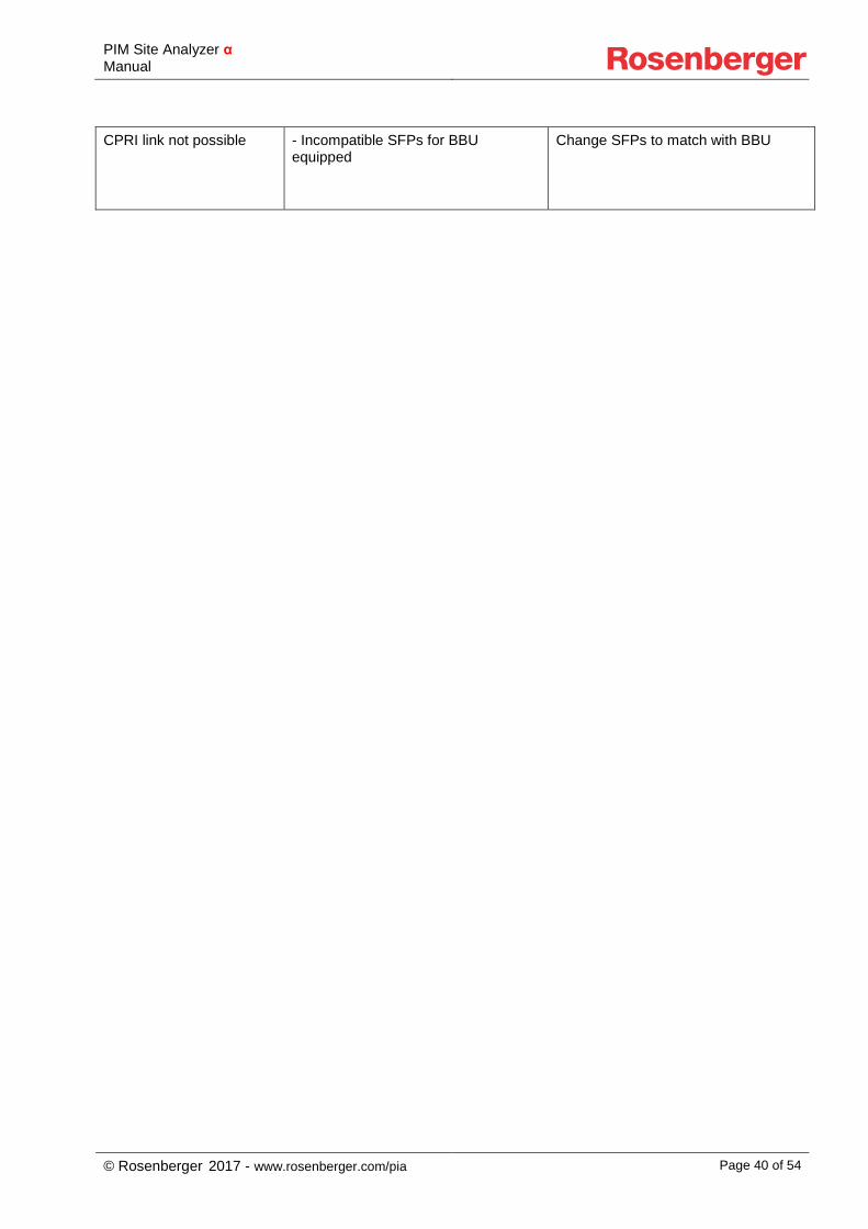
CPRI link not possible - Incompatible SFPs for BBU equipped
Change SFPs to match with BBU
PIM Site Analyzer α Manual
© Rosenberger 2017 - www.rosenberger.com/pia Page 41 of 54
11 Technical Specifications
11.1 Base Unit
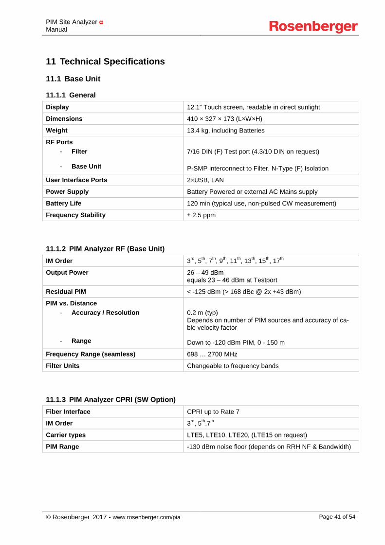
11.1.1 General Display 12.1” Touch screen, readable in direct sunlight
Dimensions 410 × 327 × 173 (L×W×H)
Weight 13.4 kg, including Batteries
RF Ports - Filter
- Base Unit
7/16 DIN (F) Test port (4.3/10 DIN on request) P-SMP interconnect to Filter, N-Type (F) Isolation
User Interface Ports 2×USB, LAN
Power Supply Battery Powered or external AC Mains supply
Battery Life 120 min (typical use, non-pulsed CW measurement)
Frequency Stability ± 2.5 ppm
11.1.2 PIM Analyzer RF (Base Unit) IM Order 3rd, 5th, 7th, 9th, 11th, 13th, 15th, 17th
Output Power 26 – 49 dBm equals 23 – 46 dBm at Testport
Residual PIM < -125 dBm (> 168 dBc @ 2x +43 dBm)
PIM vs. Distance - Accuracy / Resolution
- Range
0.2 m (typ) Depends on number of PIM sources and accuracy of ca-ble velocity factor Down to -120 dBm PIM, 0 - 150 m
Frequency Range (seamless) 698 … 2700 MHz
Filter Units Changeable to frequency bands
11.1.3 PIM Analyzer CPRI (SW Option) Fiber Interface CPRI up to Rate 7
IM Order 3rd, 5th,7th
Carrier types LTE5, LTE10, LTE20, (LTE15 on request)
PIM Range -130 dBm noise floor (depends on RRH NF & Bandwidth)
PIM Site Analyzer α Manual
© Rosenberger 2017 - www.rosenberger.com/pia Page 42 of 54
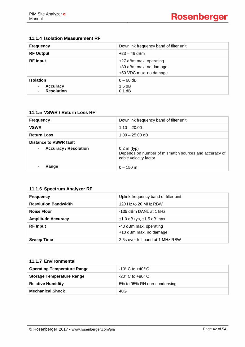
11.1.4 Isolation Measurement RF Frequency Downlink frequency band of filter unit
RF Output +23 – 46 dBm
RF Input +27 dBm max. operating +30 dBm max. no damage +50 VDC max. no damage
Isolation - Accuracy - Resolution
0 – 60 dB 1.5 dB 0.1 dB
11.1.5 VSWR / Return Loss RF Frequency Downlink frequency band of filter unit
VSWR 1.10 – 20.00
Return Loss 1.00 – 25.00 dB
Distance to VSWR fault - Accuracy / Resolution
- Range
0.2 m (typ) Depends on number of mismatch sources and accuracy of cable velocity factor 0 – 150 m
11.1.6 Spectrum Analyzer RF Frequency Uplink frequency band of filter unit
Resolution Bandwidth 120 Hz to 20 MHz RBW
Noise Floor -135 dBm DANL at 1 kHz
Amplitude Accuracy ±1.0 dB typ, ±1.5 dB max
RF Input -40 dBm max. operating +10 dBm max. no damage
Sweep Time 2.5s over full band at 1 MHz RBW
11.1.7 Environmental Operating Temperature Range -10° C to +40° C
Storage Temperature Range -20° C to +80° C
Relative Humidity 5% to 95% RH non-condensing
Mechanical Shock 40G
PIM Site Analyzer α Manual
© Rosenberger 2017 - www.rosenberger.com/pia Page 43 of 54
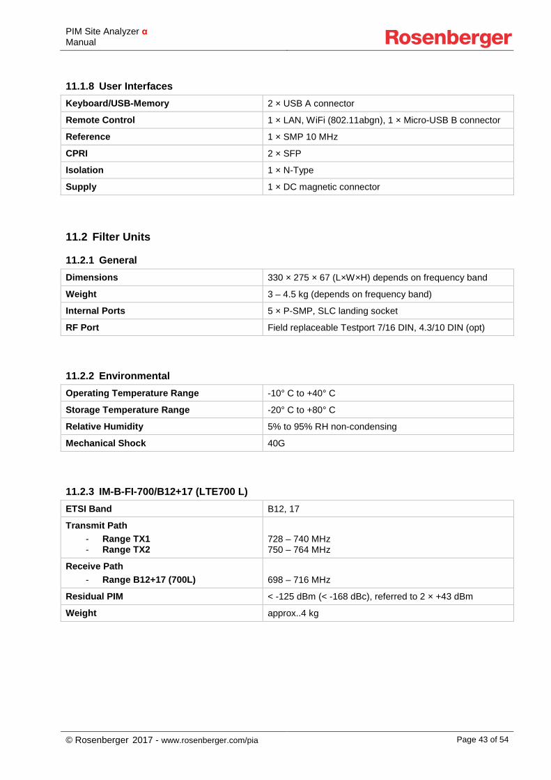
11.1.8 User Interfaces Keyboard/USB-Memory 2 × USB A connector
Remote Control 1 × LAN, WiFi (802.11abgn), 1 × Micro-USB B connector
Reference 1 × SMP 10 MHz
CPRI 2 × SFP
Isolation 1 × N-Type
Supply 1 × DC magnetic connector
11.2 Filter Units
11.2.1 General Dimensions 330 × 275 × 67 (L×W×H) depends on frequency band
Weight 3 – 4.5 kg (depends on frequency band)
Internal Ports 5 × P-SMP, SLC landing socket
RF Port Field replaceable Testport 7/16 DIN, 4.3/10 DIN (opt)
11.2.2 Environmental Operating Temperature Range -10° C to +40° C
Storage Temperature Range -20° C to +80° C
Relative Humidity 5% to 95% RH non-condensing
Mechanical Shock 40G
11.2.3 IM-B-FI-700/B12+17 (LTE700 L) ETSI Band B12, 17
Transmit Path - Range TX1 - Range TX2
728 – 740 MHz 750 – 764 MHz
Receive Path - Range B12+17 (700L)
698 – 716 MHz
Residual PIM < -125 dBm (< -168 dBc), referred to 2 × +43 dBm
Weight approx..4 kg
PIM Site Analyzer α Manual
© Rosenberger 2017 - www.rosenberger.com/pia Page 44 of 54
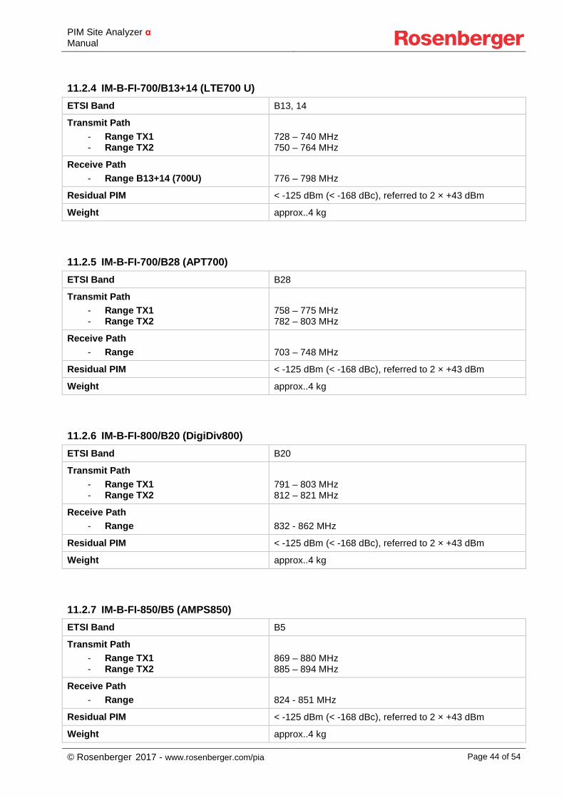
11.2.4 IM-B-FI-700/B13+14 (LTE700 U) ETSI Band B13, 14
Transmit Path - Range TX1 - Range TX2
728 – 740 MHz 750 – 764 MHz
Receive Path - Range B13+14 (700U)
776 – 798 MHz
Residual PIM < -125 dBm (< -168 dBc), referred to 2 × +43 dBm
Weight approx..4 kg
11.2.5 IM-B-FI-700/B28 (APT700) ETSI Band B28
Transmit Path - Range TX1 - Range TX2
758 – 775 MHz 782 – 803 MHz
Receive Path - Range
703 – 748 MHz
Residual PIM < -125 dBm (< -168 dBc), referred to 2 × +43 dBm
Weight approx..4 kg
11.2.6 IM-B-FI-800/B20 (DigiDiv800) ETSI Band B20
Transmit Path - Range TX1 - Range TX2
791 – 803 MHz 812 – 821 MHz
Receive Path - Range
832 - 862 MHz
Residual PIM < -125 dBm (< -168 dBc), referred to 2 × +43 dBm
Weight approx..4 kg
11.2.7 IM-B-FI-850/B5 (AMPS850) ETSI Band B5
Transmit Path - Range TX1 - Range TX2
869 – 880 MHz 885 – 894 MHz
Receive Path - Range
824 - 851 MHz
Residual PIM < -125 dBm (< -168 dBc), referred to 2 × +43 dBm
Weight approx..4 kg
PIM Site Analyzer α Manual
© Rosenberger 2017 - www.rosenberger.com/pia Page 45 of 54
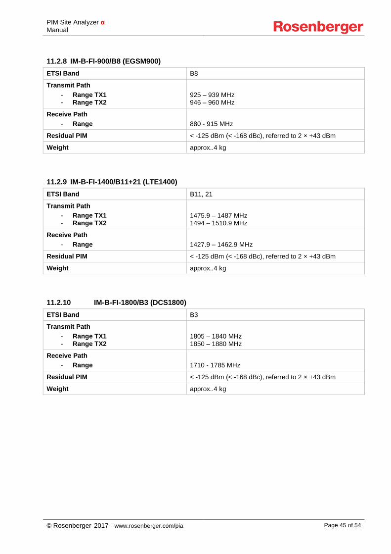
11.2.8 IM-B-FI-900/B8 (EGSM900) ETSI Band B8
Transmit Path - Range TX1 - Range TX2
925 – 939 MHz 946 – 960 MHz
Receive Path - Range
880 - 915 MHz
Residual PIM < -125 dBm (< -168 dBc), referred to 2 × +43 dBm
Weight approx..4 kg
11.2.9 IM-B-FI-1400/B11+21 (LTE1400) ETSI Band B11, 21
Transmit Path - Range TX1 - Range TX2
1475.9 – 1487 MHz 1494 – 1510.9 MHz
Receive Path - Range
1427.9 – 1462.9 MHz
Residual PIM < -125 dBm (< -168 dBc), referred to 2 × +43 dBm
Weight approx..4 kg
11.2.10 IM-B-FI-1800/B3 (DCS1800) ETSI Band B3
Transmit Path - Range TX1 - Range TX2
1805 – 1840 MHz 1850 – 1880 MHz
Receive Path - Range
1710 - 1785 MHz
Residual PIM < -125 dBm (< -168 dBc), referred to 2 × +43 dBm
Weight approx..4 kg
PIM Site Analyzer α Manual
© Rosenberger 2017 - www.rosenberger.com/pia Page 46 of 54
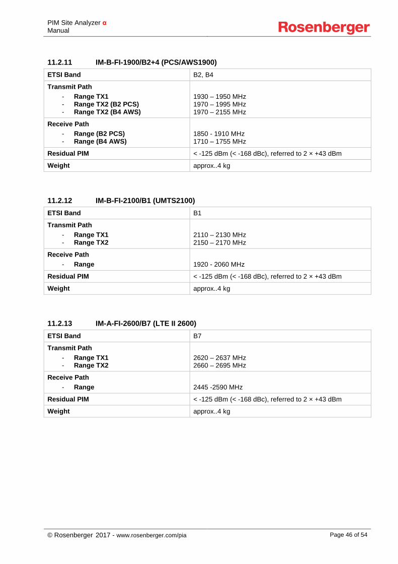
11.2.11 IM-B-FI-1900/B2+4 (PCS/AWS1900) ETSI Band B2, B4
Transmit Path - Range TX1 - Range TX2 (B2 PCS) - Range TX2 (B4 AWS)
1930 – 1950 MHz 1970 – 1995 MHz 1970 – 2155 MHz
Receive Path - Range (B2 PCS) - Range (B4 AWS)
1850 - 1910 MHz 1710 – 1755 MHz
Residual PIM < -125 dBm (< -168 dBc), referred to 2 × +43 dBm
Weight approx..4 kg
11.2.12 IM-B-FI-2100/B1 (UMTS2100) ETSI Band B1
Transmit Path - Range TX1 - Range TX2
2110 – 2130 MHz 2150 – 2170 MHz
Receive Path - Range
1920 - 2060 MHz
Residual PIM < -125 dBm (< -168 dBc), referred to 2 × +43 dBm
Weight approx..4 kg
11.2.13 IM-A-FI-2600/B7 (LTE II 2600) ETSI Band B7
Transmit Path - Range TX1 - Range TX2
2620 – 2637 MHz 2660 – 2695 MHz
Receive Path - Range
2445 -2590 MHz
Residual PIM < -125 dBm (< -168 dBc), referred to 2 × +43 dBm
Weight approx..4 kg
PIM Site Analyzer α Manual
© Rosenberger 2017 - www.rosenberger.com/pia Page 47 of 54
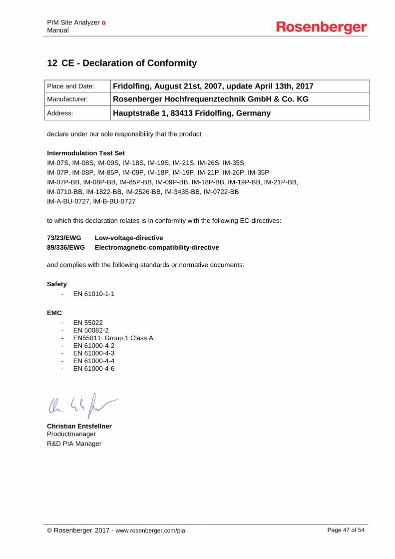
12 CE - Declaration of Conformity
Place and Date: Fridolfing, August 21st, 2007, update April 13th, 2017 Manufacturer: Rosenberger Hochfrequenztechnik GmbH & Co. KG Address: Hauptstraße 1, 83413 Fridolfing, Germany declare under our sole responsibility that the product Intermodulation Test Set IM-07S, IM-08S, IM-09S, IM-18S, IM-19S, IM-21S, IM-26S, IM-35S IM-07P, IM-08P, IM-85P, IM-09P, IM-18P, IM-19P, IM-21P, IM-26P, IM-35P IM-07P-BB, IM-08P-BB, IM-85P-BB, IM-09P-BB, IM-18P-BB, IM-19P-BB, IM-21P-BB, IM-0710-BB, IM-1822-BB, IM-2526-BB, IM-3435-BB, IM-0722-BB IM-A-BU-0727, IM-B-BU-0727 to which this declaration relates is in conformity with the following EC-directives: 73/23/EWG Low-voltage-directive 89/336/EWG Electromagnetic-compatibility-directive and complies with the following standards or normative documents: Safety
- EN 61010-1-1 EMC
- EN 55022 - EN 50082-2 - EN55011: Group 1 Class A - EN 61000-4-2 - EN 61000-4-3 - EN 61000-4-4 - EN 61000-4-6
Christian Entsfellner Productmanager R&D PIA Manager
PIM Site Analyzer α Manual
© Rosenberger 2017 - www.rosenberger.com/pia Page 48 of 54
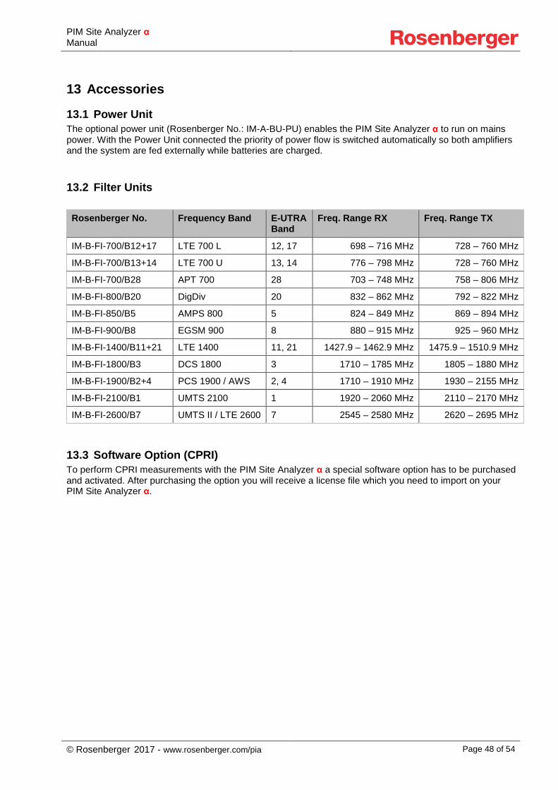
13 Accessories
13.1 Power Unit The optional power unit (Rosenberger No.: IM-A-BU-PU) enables the PIM Site Analyzer α to run on mains power. With the Power Unit connected the priority of power flow is switched automatically so both amplifiers and the system are fed externally while batteries are charged.
13.2 Filter Units
Rosenberger No. Frequency Band E-UTRA Band
Freq. Range RX Freq. Range TX
IM-B-FI-700/B12+17 LTE 700 L 12, 17 698 – 716 MHz 728 – 760 MHz
IM-B-FI-700/B13+14 LTE 700 U 13, 14 776 – 798 MHz 728 – 760 MHz
IM-B-FI-700/B28 APT 700 28 703 – 748 MHz 758 – 806 MHz
IM-B-FI-800/B20 DigDiv 20 832 – 862 MHz 792 – 822 MHz
IM-B-FI-850/B5 AMPS 800 5 824 – 849 MHz 869 – 894 MHz
IM-B-FI-900/B8 EGSM 900 8 880 – 915 MHz 925 – 960 MHz
IM-B-FI-1400/B11+21 LTE 1400 11, 21 1427.9 – 1462.9 MHz 1475.9 – 1510.9 MHz
IM-B-FI-1800/B3 DCS 1800 3 1710 – 1785 MHz 1805 – 1880 MHz
IM-B-FI-1900/B2+4 PCS 1900 / AWS 2, 4 1710 – 1910 MHz 1930 – 2155 MHz
IM-B-FI-2100/B1 UMTS 2100 1 1920 – 2060 MHz 2110 – 2170 MHz
IM-B-FI-2600/B7 UMTS II / LTE 2600 7 2545 – 2580 MHz 2620 – 2695 MHz
13.3 Software Option (CPRI) To perform CPRI measurements with the PIM Site Analyzer α a special software option has to be purchased and activated. After purchasing the option you will receive a license file which you need to import on your PIM Site Analyzer α.

PIM Site Analyzer α Manual
© Rosenberger 2017 - www.rosenberger.com/pia Page 49 of 54
13.4 Base Unit Bag
For protecting and carrying the PIM Site Analyzer α Base Unit Rosenberger offers a bag (Rosenberger No .IM-B-ACSRY-BAG-BU).
• Handy carry bag for PIM Site Analyzer α Base Unit • Shoulder belt and carrying strap • Protects α in harsh environment and during transportation • Allows easy access to all interfaces of α • Filters can be changed while α is packed in bag
Material: Nylon, UV protected Color: Dark & light grey Dimensions (L×W×H): 500 × 430 × 200 Weight: 1.55 kg
13.5 Accessory Backpack
For protecting and carrying Accessories of the PIM Site Analyzer α Rosenberger offers a backpack (Rosenberger No . IM-A-ACSRY-BACKPACK). The backpack can hold one α Filter Unit, Batteries, Load, Tools and Jumpers. The reinforced jacked protects accessories in harsh environment and during transportation
PIM Site Analyzer α Manual
© Rosenberger 2017 - www.rosenberger.com/pia Page 50 of 54
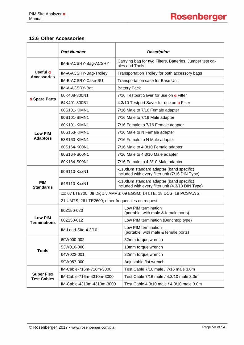
13.6 Other Accessories
Part Number Description
Useful α Accessories
IM-B-ACSRY-Bag-ACSRY Carrying bag for two Filters, Batteries, Jumper test ca-bles and Tools
IM-A-ACSRY-Bag-Trolley Transportation Trolley for both accessory bags
IM-B-ACSRY-Case-BU Transportation case for Base Unit
IM-A-ACSRY-Bat Battery Pack
α Spare Parts 60K408-800N1 7/16 Testport Saver for use on α Filter
64K401-800B1 4.3/10 Testport Saver for use on α Filter
Low PIM Adaptors
60S101-KIMN1 7/16 Male to 7/16 Female adapter
60S101-SIMN1 7/16 Male to 7/16 Male adapter
60K101-KIMN1 7/16 Female to 7/16 Female adapter
60S153-KIMN1 7/16 Male to N Female adapter
53S160-KIMN1 7/16 Female to N Male adapter
60S164-K00N1 7/16 Male to 4.3/10 Female adapter
60S164-S00N1 7/16 Male to 4.3/10 Male adapter
60K164-S00N1 7/16 Female to 4.3/10 Male adapter
PIM Standards
60S110-KxxN1 -110dBm standard adapter (band specific) included with every filter unit (7/16 DIN Type)
64S110-KxxN1 -110dBm standard adapter (band specific) included with every filter unit (4.3/10 DIN Type)
xx: 07 LTE700; 08 DigDiv|AMPS; 09 EGSM; 14 LTE, 18 DCS; 19 PCS/AWS;
21 UMTS; 26 LTE2600; other frequencies on request
Low PIM Terminations
60Z150-020 Low PIM termination (portable, with male & female ports)
60Z150-012 Low PIM termination (Benchtop type)
IM-Load-Site-4.3/10 Low PIM termination (portable, with male & female ports)
Tools
60W000-002 32mm torque wrench
53W010-000 18mm torque wrench
64W022-001 22mm torque wrench
99W057-000 Adjustable flat wrench
Super Flex Test Cables
IM-Cable-716m-716m-3000 Test Cable 7/16 male / 7/16 male 3.0m
IM-Cable-716m-4310m-3000 Test Cable 7/16 male / 4.3/10 male 3.0m
IM-Cable-4310m-4310m-3000 Test Cable 4.3/10 male / 4.3/10 male 3.0m
PIM Site Analyzer α Manual
© Rosenberger 2017 - www.rosenberger.com/pia Page 51 of 54
14 Support and Sales Locations
14.1 Europe, Middle East, Africa
Rosenberger Hochfrequenztechnik GmbH & Co. KG Hauptstraße 1 83413 Fridolfing, Germany Phone +49 8684 18-0 Fax +49 8684 18-1499 [email protected] www.rosenberger.com Rosenberger Site Solutions GmbH Mayerhofen 45A 83410 Laufen, Germany Phone +49 8684 18-5000 Fax +49 8684 18-1499 [email protected] www.rosenberger.com/siso
14.2 Americas Rosenberger Site Solutions, LLC P.O. Box 8817, Lake Charles, LA 70606, USA Phone +1 337 598 5250 Fax +1 337 598 5290 [email protected] www.rlss.us
14.3 Brazil Rosenberger Domex Telecom Cabletech Avenue, 601 Guaramirin CEP 12295-230 Cacapava – Sao Paulo, Brazil Phone +55 12 3221 8500 Fax +55 12 3221 8543 [email protected] www.rosenberger.com
PIM Site Analyzer α Manual
© Rosenberger 2017 - www.rosenberger.com/pia Page 52 of 54
14.4 Asia Pacific Rosenberger Asia Pacific Electronic Co., Ltd. No. 3, Anxiang Road, Block B Tianzhu Airport Industrial Zone Beijing, 101300, PR China Phone +86 10 80 48 1995 Fax +86 10 80 48 2438 [email protected] www.rosenbergerap.com
14.5 India Rosenberger Electronic Co. (India) Pvt Limited Plot No. N3B3, Phase-IV Verna Industrial Estate IND - 403722 Goa [email protected] www.rosenbergerap.com

PIM Site Analyzer α Manual
© Rosenberger 2017 - www.rosenberger.com/pia Page 53 of 54
Status May 2017 – Technical modifications and errors excepted. Similar images.
PIM Site Analyzer α Manual
© Rosenberger 2017 - www.rosenberger.com/pia Page 54 of 54
Hochfrequenztechnik GmbH & Co. KG Hauptstraße 1 | 83413 Fridolfing P.O. Box 1260 | 84526 Tittmoning Germany Phone +49 8684 18-0 [email protected] www.rosenberger.com Certified by ISO/TS 16949 · DIN EN 9100 · ISO 9001 · ISO 14001 Order No. pA 352613 · EIM-B-ACSRY-OM-en 5/2017 Rosenberger® is a registered trademark by Rosenberger Hochfrequenztechnik GmbH & Co. KG. All rights reserved.