Embed Size (px)
Citation preview

8/17/2019 PLACA b150 Pro Gaming
http://slidepdf.com/reader/full/placa-b150-pro-gaming 1/92
M o
t h
e r b
o a
r dB150 PRO GAMING/AURA

8/17/2019 PLACA b150 Pro Gaming
http://slidepdf.com/reader/full/placa-b150-pro-gaming 2/92
ii
E10939
First Edition (V1)October 2015
Copyright © 2015 ASUSTeK COMPUTER INC. All Rights Reserved.
No part of this manual, including the products and software described in it, may be reproduced,transmitted, transcribed, stored in a retrieval system, or translated into any language in any form or by anymeans, except documentation kept by the purchaser for backup purposes, without the express writtenpermission of ASUSTeK COMPUTER INC. (“ASUS”).
Product warranty or service will not be extended if: (1) the product is repaired, modied or altered, unlesssuch repair, modication of alteration is authorized in writing by ASUS; or (2) the serial number of theproduct is defaced or missing.
ASUS PROVIDES THIS MANUAL “AS IS” WITHOUT WARRANTY OF ANY KIND, EITHER EXPRESSOR IMPLIED, INCLUDING BUT NOT LIMITED TO THE IMPLIED WARRANTIES OR CONDITIONS OFMERCHANTABILITY OR FITNESS FOR A PARTICULAR PURPOSE. IN NO EVENT SHALL ASUS, ITSDIRECTORS, OFFICERS, EMPLOYEES OR AGENTS BE LIABLE FOR ANY INDIRECT, SPECIAL,
INCIDENTAL, OR CONSEQUENTIAL DAMAGES (INCLUDING DAMAGES FOR LOSS OF PROFITS,LOSS OF BUSINESS, LOSS OF USE OR DATA, INTERRUPTION OF BUSINESS AND THE LIKE),EVEN IF ASUS HAS BEEN ADVISED OF THE POSSIBILITY OF SUCH DAMAGES ARISING FROM ANYDEFECT OR ERROR IN THIS MANUAL OR PRODUCT.
SPECIFICATIONS AND INFORMATION CONTAINED IN THIS MANUAL ARE FURNISHED FORINFORMATIONAL USE ONLY, AND ARE SUBJECT TO CHANGE AT ANY TIME WITHOUT NOTICE,AND SHOULD NOT BE CONSTRUED AS A COMMITMENT BY ASUS. ASUS ASSUMES NORESPONSIBILITY OR LIABILITY FOR ANY ERRORS OR INACCURACIES THAT MAY APPEAR IN THISMANUAL, INCLUDING THE PRODUCTS AND SOFTWARE DESCRIBED IN IT.
Products and corporate names appearing in this manual may or may not be registered trademarks orcopyrights of their respective companies, and are used only for identication or explanation and to theowners’ benet, without intent to infringe.
Offer to Provide Source Code of Certain SoftwareThis product contains copyrighted software that is licensed under the General Public License (“GPL”),under the Lesser General Public License Version (“LGPL”) and/or other Free Open Source SoftwareLicenses. Such software in this product is distributed without any warranty to the extent permitted by theapplicable law. Copies of these licenses are included in this product.
Where the applicable license entitles you to the source code of such software and/or other additional data,you may obtain it for a period of three years after our last shipment of the product, either
(1) for free by downloading it from http://support.asus.com/download
or
(2) for the cost of reproduction and shipment, which is dependent on the preferred carrier and the locationwhere you want to have it shipped to, by sending a request to:
ASUSTeK Computer Inc.
Legal Compliance Dept.
15 Li Te Rd.,
Beitou, Taipei 112
Taiwan
In your request please provide the name, model number and version, as stated in the About Box of theproduct for which you wish to obtain the corresponding source code and your contact details so that wecan coordinate the terms and cost of shipment with you.
The source code will be distributed WITHOUT ANY WARRANTY and licensed under the same license asthe corresponding binary/object code.
This offer is valid to anyone in receipt of this information.ASUSTeK is eager to duly provide complete source code as required under various Free Open SourceSoftware licenses. If however you encounter any problems in obtaining the full corresponding sourcecode we would be much obliged if you give us a notication to the email address [email protected], statingthe product and describing the problem (please DO NOT send large attachments such as source codearchives, etc. to this email address).

8/17/2019 PLACA b150 Pro Gaming
http://slidepdf.com/reader/full/placa-b150-pro-gaming 3/92
iii
Contents
Safety information ...................................................................................... iv
About this guide ......................................................................................... iv
Package contents ....................................................................................... vi
B150 PRO GAMING/AURA specications summary ............................... vi
Chapter 1: Product introduction
1.1 Before you proceed ..................................................................... 1-1
1.2 Motherboard overview ................................................................. 1-1
1.3 Central Processing Unit (CPU) ................................................... 1-3
1.4 System memory ........................................................................... 1-7
1.5 Expansion slots.......................................................................... 1-121.6 Jumpers ...................................................................................... 1-14
1.7 Connectors ................................................................................. 1-15
1.8 Onboard LED .............................................................................. 1-25
1.9 Software support ........................................................................ 1-27
Chapter 2: BIOS information
2.1 Managing and updating your BIOS ............................................ 2-1
2.2 BIOS setup program .................................................................... 2-6
2.3 My Favorites ............................................................................... 2-13
2.4 Main menu .................................................................................. 2-14
2.5 Ai Tweaker menu ........................................................................ 2-16
2.6 Advanced menu ......................................................................... 2-24
2.7 Monitor menu ............................................................................. 2-32
2.8 Boot menu .................................................................................. 2-36
2.9 Tool menu ................................................................................... 2-402.10 Exit menu .................................................................................... 2-42
2.11 Installing an operating system ................................................. 2-43
Appendices
Notices .......................................................................................................A-1
ASUS contact information .......................................................................A-4

8/17/2019 PLACA b150 Pro Gaming
http://slidepdf.com/reader/full/placa-b150-pro-gaming 4/92
iv
Safety information
Electrical safety
• To prevent electrical shock hazard, disconnect the power cable from the electrical outletbefore relocating the system.
• When adding or removing devices to or from the system, ensure that the power cablesfor the devices are unplugged before the signal cables are connected. If possible,disconnect all power cables from the existing system before you add a device.
• Before connecting or removing signal cables from the motherboard, ensure that allpower cables are unplugged.
• Seek professional assistance before using an adapter or extension cord. These devices
could interrupt the grounding circuit.
• Ensure that your power supply is set to the correct voltage in your area. If you are notsure about the voltage of the electrical outlet you are using, contact your local power
company.
• If the power supply is broken, do not try to x it by yourself. Contact a qualied servicetechnician or your retailer.
Operation safety
• Before installing the motherboard and adding components, carefully read all the manualsthat came with the package.
• Before using the product, ensure all cables are correctly connected and the powercables are not damaged. If you detect any damage, contact your dealer immediately.
• To avoid short circuits, keep paper clips, screws, and staples away from connectors,slots, sockets and circuitry.
• Avoid dust, humidity, and temperature extremes. Do not place the product in any areawhere it may be exposed to moisture.
• Place the product on a stable surface.
• If you encounter technical problems with the product, contact a qualied servicetechnician or your retailer.
About this guideThis user guide contains the information you need when installing and conguring themotherboard.
How this guide is organized
This guide contains the following parts:
• Chapter 1: Product introduction
This chapter describes the features of the motherboard and the new technology it
supports. It includes descriptions of the switches, jumpers, and connectors on themotherboard.
• Chapter 2: BIOS information
This chapter discusses changing system settings through the BIOS Setup menus.
Detailed descriptions for the BIOS parameters are also provided.
8/17/2019 PLACA b150 Pro Gaming
http://slidepdf.com/reader/full/placa-b150-pro-gaming 5/92
v
Where to nd more information
Refer to the following sources for additional information and for product and softwareupdates.
1. ASUS websites
The ASUS website provides updated information on ASUS hardware and softwareproducts. Refer to the ASUS contact information.
2. Optional documentation
Your product package may include optional documentation, such as warranty yers,that may have been added by your dealer. These documents are not part of thestandard package.
Conventions used in this guideTo ensure that you perform certain tasks properly, take note of the following symbols usedthroughout this manual.
DANGER/WARNING: Information to prevent injury to yourself whencompleting a task.
CAUTION: Information to prevent damage to the components whencompleting a task
IMPORTANT: Instructions that you MUST follow to complete a task.
NOTE: Tips and additional information to help you complete a task.
Typography
Bold text Indicates a menu or an item to select.
Italics Used to emphasize a word or a phrase.
<Key> Keys enclosed in the less-than and greater-than signmeans that you must press the enclosed key.
Example: <Enter> means that you must press the Enter orReturn key.
<Key1> + <Key2> + <Key3> If you must press two or more keys simultaneously, the keynames are linked with a plus sign (+).

8/17/2019 PLACA b150 Pro Gaming
http://slidepdf.com/reader/full/placa-b150-pro-gaming 6/92
vi
B150 PRO GAMING/AURA specications summary
(continued on the next page)
Package contentsCheck your motherboard package for the following items.
Motherboard ASUS Gaming Motherboard – B150 PRO GAMING/AURA
Cables 4 x Serial ATA 6.0 Gb/s cables
Accessories
1 x I/O Shield
1 x PRO GAMING cable labels
1 x M.2 screw package
1 x pack of cable tie
Application DVD Support DVD
Documentation User Guide
If any of the above items is damaged or missing, contact your retailer.
CPU
LGA1151 socket for 6th Generation Intel ® Core™ i7 / i5 / i3, Pentium ® , andCeleron ® processors
Supports Intel ® 14nm CPU
Supports Intel ® Turbo Boost Technology 2.0*
* The Intel ® Turbo Boost Technology 2.0 support depends on the CPU types.
** Refer to www.asus.com for Intel ® CPU support list.
Chipset Intel ® B150 Express Chipset
Memory
4 x DIMMs, maximum 64 GB, DDR4 2133 MHz, non-ECC, un-buffered memory*
Dual-channel memory architecture
Supports Intel ® Extreme Memory Prole (XMP)
* Hyper DIMM support is subject to the physical characteristics of individual CPUs. Pleaserefer to Memory QVL (Qualied Vendors List) for details.
** Refer to www.asus.com or this user manual for the Memory QVL (Qualied VendorsList).
Graphics
Integrated graphics processor - Intel ® HD Graphics support
Multi-VGA output support: HDMI, D-Sub ports
- Supports HDMI 1.4b with maximum resolution of 4096 x 2160 @24Hz
- Supports D-Sub with maximum resolution of 1920 x 1200 @60Hz
Supports Intel ® InTruTM 3D, Quick Sync Video, Intel ® Clear Video HD Technology,and Intel ® InsiderTM
Maximum shared memory of 1024 MB
Multi-GPUSupport
Supports AMD ® 2-Way/ Quad-GPU CrossFireX™ Technology
Expansionslots
1 x PCI Express 3.0 x16 slot (at x16 mode)
1 x PCI Express 3.0 x16 slot (max. at x4 mode, compatible with PCIe x1 and x4devices)
2 x PCI Express 3.0 x1 slots*
2 x PCI slots
* When PCIE x16_2 is occupied by x4 or faster devices, PCIE x1_1 and PCIE x1_2 will bedisabled.
8/17/2019 PLACA b150 Pro Gaming
http://slidepdf.com/reader/full/placa-b150-pro-gaming 7/92
vii
B150 PRO GAMING/AURA specications summary
(continued on the next page)
Audio
SupremeFX 8-Channel High Denition Audio CODEC
- Supports Jack-detection, Multi-streaming, and Front Panel MIC Jack-retasking
- High quality 115dB SNR stereo playback output
Audio Features:
- SupremeFX Shielding™ Technology
- Headphone AMP
- Optical S/PDIF out port at back panel
- Sonic Radar II
Storage
Intel ® B150 Express Chipset
- 6 x SATA 6.0 Gb/s connectors
- 1 x M.2 Socket 3 with M Key, type 2242/2260/2280/22110 storage devicessupport (both SATA & PCIE x2 mode)*
* When the M.2 Socket 3 is operating in SATA mode, SATA port 1 will be disabled.
LAN
Intel ® Gigabit LAN
Anti-surge LANGuard
GameFirst technology
USB
ASMedia ® USB 3.1 controller - supports ASUS USB 3.1 Boost:
- 2 x USB 3.1 ports (1 Type-A, red; 1 Type-C, black at back panel)
Intel ® B150 Express Chipset - supports ASUS USB 3.1 Boost:
- 6 x USB 3.0 / 2.0 ports (2 ports at mid-board, 4 ports at rear panel, blue)
- 6 x USB 2.0/1.1 ports (4 ports at mid-board; 2 ports at back panel)*
* Two USB2.0 ports at mid-board share with the ROG extension (ROG_EXT) port.
ASUSgamingfeatures
Gamer’s Guardian- DIGI+ VRM
- DRAM Overcurrent Protection
- ESD Guards on VGA, LAN, Audio, KBMS and USB 3.0/ 2.0 ports
- Highly Durable Components
- Stainless Steel Back I/O
- Q-Design (Q-Shield, Q-DIMM, Q-LED, Q-Slot)
Performance Level Up- DIGI+ VRM
- AI Suite 3
- Fan Xpert 3 featuring Fan Auto Tuning function and multiple thermistors selectionfor optimized system cooling control
- UEFI BIOS EZ Mode (CrashFree BIOS 3, EZ Flash 3)
- RAMCache - Speed your game loads
ASUS Exclusive Features- ASUS CPU-Z
- USB 3.1 Boost featuring speedy USB 3.1 transmission
- AI Charger+
- Disk Unlocker
- Push Notice
- Media Streamer- Aura: RGB lighting control
8/17/2019 PLACA b150 Pro Gaming
http://slidepdf.com/reader/full/placa-b150-pro-gaming 8/92
viii
B150 PRO GAMING/AURA specications summary
Specications are subject to change without notice.
Rear Panel I/Oports
1 x PS/2 keyboard/mouse combo port
1 x Optical S/PDIF out
1 x HDMI port
1 x D-Sub port1 x LAN (RJ-45) port
2 x USB 3.1 ports (1 Type-A, red; 1 Type-C, black)
4 x USB 3.0 / 2.0 ports
2 x USB 2.0 ports
8-channel audio I/O ports
Internalconnectors
1 x 19-pin USB 3.0 / 2.0 connector support additional 2 USB 3.0 / 2.0 ports
2 x USB 2.0 / 1.1 connectors support additional 4 USB 2.0 / 1.1 ports (Oneconnector shares with the ROG_EXT header)
1 x System panel connector
1 x Front panel audio connector (AAFP)
6 x SATA 6.0 Gb/s connectors
1 x M.2 Socket 3 for M Key, type 2242/2260/2280/22110 devices
1 x 4-pin CPU fan connector
1 x 4-pin Water Pump connector
3 x Chassis fan connectors (4-pin) for both 3-pin (DC mode) and 4-pin (PWMmode) coolers control
1 x Thermal sensor connector
1 x COM header
1 x TPM header1 X CPU Over Voltage jumper (CPU_OV)
1 x 2-pin Clear CMOS jumper
1 x 24-pin EATX power connector
1 x 8-pin ATX 12V power connector
1 x ROG extension (ROG_EXT) header
BIOS features
128 Mb Flash ROM, UEFI AMI BIOS, PnP, DMI 3.0, WfM 2.0, SM BIOS 3.0,ACPI 5.0, Multi-language BIOS, ASUS EZ Flash 3, CrashFree BIOS 3, F6Q-fan Control, F3 My Favorites, F9 Quick Note, Last Modied Log, F12PrintScreen function, and ASUS DRAM SPD (Serial Presence Detect) memory
informationManageability WfM 2.0, DMI 3.0, WOL by PME, PXE
Support DVD
Drivers
ASUS utilities
EZ Update
Anti-virus software (OEM version)
OS support
Windows ® 10*
Windows ® 8.1*
Windows ® 7
* 64-bit supported only
Form factor ATX form factor: 12.0 in. x 9.6 in. (30.5 cm x 24.4 cm)

8/17/2019 PLACA b150 Pro Gaming
http://slidepdf.com/reader/full/placa-b150-pro-gaming 9/92
ASUS B150 PRO GAMING/AURA 1-1
Product introduction 11.1 Before you proceedTake note of the following precautions before you install motherboard components or changeany motherboard settings.
• Unplug the power cord from the wall socket before touching any component.
• Before handling components, use a grounded wrist strap or touch a safely groundedobject or a metal object, such as the power supply case, to avoid damaging them dueto static electricity.
• Before you install or remove any component, ensure that the ATX power supply isswitched off or the power cord is detached from the power supply. Failure to do somay cause severe damage to the motherboard, peripherals, or components.
1.2 Motherboard overviewBefore you install the motherboard, study the conguration of your chassis to ensure that the
motherboard ts.
Unplug the power cord before installing or removing the motherboard. Failure to do so cancause you physical injury and damage to motherboard components.
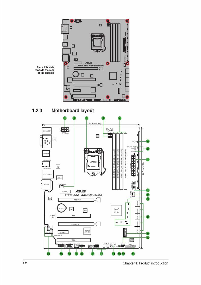
1.2.1 Placement direction
When installing the motherboard, place it into the chassis in the correct orientation. The edgewith external ports goes to the rear part of the chassis as indicated in the image.
1.2.2 Screw holes
Place nine screws into the holes indicated by circles to secure the motherboard to the
chassis.
Do not overtighten the screws! Doing so can damage the motherboard.
8/17/2019 PLACA b150 Pro Gaming
http://slidepdf.com/reader/full/placa-b150-pro-gaming 10/92
1-2 Chapter 1: Product introduction
Place this sidetowards the rear
of the chassis
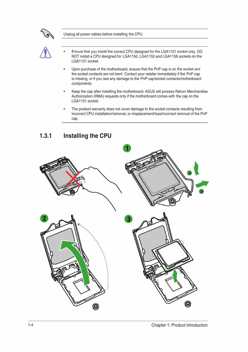
1.2.3 Motherboard layout
PCIEX16_1
CPU_LED
DRAM_LED
VGA_LED
BOOT_DEVICE_LED
RGB_LED
PCIEX16_2
PCI1
PCI2
PCIEX1_2
PCIEX1_1
M . 2 ( S O C K E T 3 )
Intel
I219V
ASM
1142
ASM
1442K
USB1112AAFP
E A T X P W R
BATTERY
Super
I/O
SupremeFX LED
SupremeFX
ALC
1150
TPUTPU
KBMS_USB78
T_SENSOR
CLRTC
CPU_OV
24.4cm(9.6in)
D D R 4 D I M M_
A 1 ( 6 4 b i t , 2 8 8 - p i n m o d u l e )
D D R 4 D I M M_
A 2 ( 6 4 b i t , 2 8 8 - p i n m o d u l e )
D D R 4 D I M M_
B 1 ( 6 4 b i t , 2 8 8 - p i n m o d u l e )
D D R 4 D I M M_
B 2 ( 6 4 b i t , 2 8 8 - p i n m o d u l e )
S A T A 6 G_
3
S A T A 6 G_
4
S A T A 6 G_
5
S A T A 6 G_
6
S A T A 6 G_
1 2
LANGuard
USB3.1_EA1
USB3_56
USB3.1_EC1
LAN_USB3_34
CHA_FAN1
C H A_
F A N 3
CHA_FAN2
CPU_FAN
W_PUMP
3 0 . 5 c m ( 1 2 . 0 i n )LGA1151
DIGI
+VRM
COM
EATX12V
U S B 3_
1 2
Intel ®
B150
TPM
ROG_EXT
128MbBIOS
PANELSB_PWR
AUDIO
USB910
V G A
H D M I
asmedia
ASM1083
21 3 42
121314 11151617181920 2
2
1
6
7
5
8
10
5
9

8/17/2019 PLACA b150 Pro Gaming
http://slidepdf.com/reader/full/placa-b150-pro-gaming 11/92
ASUS B150 PRO GAMING/AURA 1-3
1.2.4 Layout contents
1.3 Central Processing Unit (CPU)This motherboard comes with a surface mount LGA1151 socket designed for 6th Generation
Intel ® Core™ i7 / i5 / i3, Pentium ® , and Celeron ® processors.
Connectors/Jumpers/Slots/LED Page
1. ATX power connectors (24-pin EATXPWR, 8-pin ATX12V) 1-20
2. CPU, water pump, and chassis fan connectors (4-pin CPU_FAN, 4-pin W_PUMP, 4-pin CHA_FAN1~3)
1-19
3. Intel ® LGA1151 CPU socket 1-3
4. DDR4 DIMM slots 1-7
5. RGB LED 1-26
6. Q LEDs (BOOT_DEVICE_LED, VGA_LED, DRAM_LED, CPU_LED) 1-26
7. USB 3.0 connector (20-1 pin USB3_12) 1-22
8. Intel ® B150 Serial ATA 6.0 Gb/s connector (7-pin SATA6G_1~6) 1-23
9. M.2 Socket 3 1-18
10. CPU Over Voltage jumper (3-pin CPU_OV) 1-15
11. System panel connector (20-5 pin PANEL) 1-24
12. Thermal sensor connector (2-pin T_SENSOR) 1-20
13. Clear RTC RAM (2-pin CLRTC) 1-14
14. Standby Power LED (SB_PWR) 1-25
15. USB 2.0 connectors (10-1 pin USB910, USB1112) 1-18
16. ROG Extension connector (18-1 pin ROG_EXT) 1-21
17. TPM connector (14-1 pin TPM) 1-22
18. Serial port connectors (10-1 pin COM) 1-1719. Front panel audio connector (10-1 pin AAFP) 1-21
20. SupremeFX LED 1-25
B150 PRO GAMING/AURA CPU socket LGA1151
8/17/2019 PLACA b150 Pro Gaming
http://slidepdf.com/reader/full/placa-b150-pro-gaming 12/92
1-4 Chapter 1: Product introduction
1.3.1 Installing the CPU
Unplug all power cables before installing the CPU.
• Ensure that you install the correct CPU designed for the LGA1151 socket only. DO
NOT install a CPU designed for LGA1150, LGA1155 and LGA1156 sockets on theLGA1151 socket.
• Upon purchase of the motherboard, ensure that the PnP cap is on the socket andthe socket contacts are not bent. Contact your retailer immediately if the PnP capis missing, or if you see any damage to the PnP cap/socket contacts/motherboardcomponents.
• Keep the cap after installing the motherboard. ASUS will process Return MerchandiseAuthorization (RMA) requests only if the motherboard comes with the cap on theLGA1151 socket.
• The product warranty does not cover damage to the socket contacts resulting from
incorrect CPU installation/removal, or misplacement/loss/incorrect removal of the PnPcap.
1
2 3
A
B

8/17/2019 PLACA b150 Pro Gaming
http://slidepdf.com/reader/full/placa-b150-pro-gaming 13/92
ASUS B150 PRO GAMING/AURA 1-5
A
B
C 54
1.3.2 CPU heatsink and fan assembly installation
Apply the Thermal Interface Materialto the CPU heatsink and CPUbefore you install the heatsink andfan if necessary.

8/17/2019 PLACA b150 Pro Gaming
http://slidepdf.com/reader/full/placa-b150-pro-gaming 14/92
1-6 Chapter 1: Product introduction
3 4
A
B
B
A
To uninstall the CPU heatsink and fan assembly
21
To install the CPU heatsink and fan assembly
2
B
A
A
B
1

8/17/2019 PLACA b150 Pro Gaming
http://slidepdf.com/reader/full/placa-b150-pro-gaming 15/92
ASUS B150 PRO GAMING/AURA 1-7
1.4 System memory
1.4.1 Overview
This motherboard comes with four Double Data Rate 4 (DDR4) Dual Inline Memory Module(DIMM) sockets.
A DDR4 module is notched differently from a DDR, DDR2, or DDR3 module. DO NOTinstall a DDR, DDR2, or DDR3 memory module to the DDR4 slot.
1.4.2 Memory congurations
You may install 2 GB, 4 GB, 8 GB, and 16 GB unbuffered non-ECC DDR4 DIMMs into theDIMM sockets. You can refer to the recommended memory population below.
Recommended memory congurations
Channel Sockets
Channel A DIMM_A1 & DIMM_A2
Channel B DIMM_B1 & DIMM_B2
B150 PRO GAMING/AURA 288-pin DDR4 DIMM sockets
D I M M_
A 1
D I M M_
A 2
D I M M_
B 1
D I M M_
B 2

8/17/2019 PLACA b150 Pro Gaming
http://slidepdf.com/reader/full/placa-b150-pro-gaming 16/92
1-8 Chapter 1: Product introduction
• The default memory operation frequency is dependent on its Serial Presence Detect(SPD), which is the standard way of accessing information from a memory module.Under the default state, some memory modules for overclocking may operate at alower frequency than the vendor-marked value. To operate at the vendor-markedor at a higher frequency, refer to section 2.5 Ai Tweaker menu for manual memoryfrequency adjustment.
• Always install the DIMMS with the same CAS Latency. For an optimum compatibility,we recommend that you install memory modules of the same version or data code
(D/C) from the same vendor. Check with the vendor to get the correct memorymodules.
• For system stability, use a more efcient memory cooling system to support a fullmemory load (4 DIMMs) or overclocking condition.
• You may install varying memory sizes in Channel A and Channel B. The systemmaps the total size of the lower-sized channel for the dual-channel conguration. Anyexcess memory from the higher-sized channel is then mapped for single-channeloperation.
• According to Intel ®
CPU spec, DIMM voltage below 1.5V is recommended to protectthe CPU.
• Due to the memory address limitation on 32-bit Windows ® OS, when you install 4GBor more memory on the motherboard, the actual usable memory for the OS can beabout 3GB or less. For effective use of memory, we recommend that you do any of thefollowing:
- Use a maximum of 3 GB system memory if you are using a 32-bit Windows ® OS.
- Install a 64-bit Windows ® OS if you want to install 4GB or more on themotherboard.
- For more details, refer to the Microsoft ® support site at http://support.microsoft.com/kb/929605/en-us.
B150 PRO GAMING/AURA motherboard memory Qualied Vendors Lists (QVL)
DDR4 3000 MHz (O.C.) capability
DDR4 2800 MHz (O.C.) capability
Vendors Part No. Size SS/DS Chip Brand Chip NO. Timing Voltage
DIMM socket support
(Optional)1 DIMM 2 DIMMs 4 DIMMs
KINGSTON HX430C15PB2K4/16 4G SS N/A Heat-Sink Package - 1.35V • • •
KINGSTON HX430C15PB2K4/16 4G SS N/A Heat-Sink Package - 1.35V • • •
G.SKILL F4-3000C15Q-16GRR 4G SS N/A Heat-Sink Package 15-15-15-35 1.35V • • •
TEAM TCD48G3000C16ABK 8G DS TEAM T4D5128HT-30 16-16-16-36 1.35V • • •
TEAM TCD44G3000C16ABK 4G SS TEAM T4D5128HT-30 16-16-16-36 1.35V • • •
PANRAM PUD43000C154G4NJW 4G SS N/A Heat-Sink Package 15-17-17-35 1.35V • • •
KINGSTON HX430C15PBK4/32 8G DS N/A Heat-Sink Package 15-16-16-39-65 1.35V • • •
Vendors Part No. Size SS/DSChip
Brand
Chip NO. Timing VoltageDIMM socket support(Optional)
1 DIMM 2 DIMMs 4 DIMMsCORSAIR CMK16GX4M4A2800C16 4G S S N/A Heat-Sink Package 16-18-18-36 1.2V • • •
G.SKILL HX428C14PB2K4/16 4G SS N/A Heat-Sink Package - 1.35V • • •
G.SKILL F4-2800C6Q-16GRK 4G SS N/A Heat-Sink Package 16-16-16-36 1.2V • •
PATRIOT PX416G280C6QK 4G SS N/A Heat-Sink Package 16-18-18-36 1.2V • • •
GLOWAY PC4-22400 4G SS SK HYNIX H5AN4G8NMFR 16-16-16-36 1.2V • • •
PANRAM PUD42800C164G4NJW 4G SS N/A Heat-Sink Package 16-18-18-36 1.25V • • •
MUSHKIN 994207F 4G SS N/A Heat-Sink Package 16-16-16-36-52 1.2V • • •
KINGSTON HX428C14PBK/32 8G DS N/A Heat-Sink Package 14-15-15-39-63 1.35V • • •

8/17/2019 PLACA b150 Pro Gaming
http://slidepdf.com/reader/full/placa-b150-pro-gaming 17/92
ASUS B150 PRO GAMING/AURA 1-9
DDR4 2666 MHz (O.C.) capability
DDR4 2400 MHz (O.C.) capability
Vendors Part No. SizeSS/ DS
ChipBrand
Chip NO. Timing VoltageDIMM socket support(Optional)
1 DIMM 2 DIMMs 4 DIMMs
CORSAIR CMK16GX4M4A2666C16 4G SS N/A Heat-Sink Package 16-16-18-35 1.2V • • •
CORSAIR CMD32GX4M4A2666C15(Ver5.29) 8G DS N/A Heat-Sink Package 15-17-17-35 1.2V • • •
CORSAIR CMD128GX4MM8A2666C15 16G DS N/A Heat-Sink Package 15-18-18-35 1.2V • • •
CRUCIAL BLE4G4D26AFEA.8FAD 8G SS N/A Heat-Sink Package 16-16-17-36 1.2V • • •
CRUCIAL BLE8G4D26AFEA.16FAD 16G DS N/A Heat-Sink Package 16-16-17-36 1.2V • • •
G.SKILL F4-2666C15Q-16GRR 4G SS N/A Heat-Sink Package 15-15-15-35 1.2V • • •
PATRIOT PX416G266C5QK 4G SS N/A Heat-Sink Package 15-15-15-35 1.2V • • •
G.SKILL F4-2666C16Q2-64GRB 8G DS N/A Heat-Sink Package 16-16-16-36 1.2V • • •
TEAM TCD48G2666C15ABK 8G DS SK
HYNIX H5AN4G8NMFR 15-15-15-35 1.2V • • •
TEAM TCD44G2666C15ABK 4G SS SEC 443
BCPB K4A4G085WD 15-15-15-35 1.2V • • •
MUSHKIN 997192F 4G SS N/A Heat-Sink Package 15-15-15-35-50
1.2V • • •
KINGSTON HX426C13PBK4/32 8G DS N/A Heat-Sink Package 13-14-14-39-60
1.35V • • •
KINGSTON HX426C15FBK4/32 8G DS N/A Heat-Sink Package - 1.2V • • •
KINGSTON HX426C15FBK4/16 4G SS N/A Heat-Sink Package - 1.2V • • •
Vendors Part No. SizeSS/ DS
ChipBrand
Chip NO. Timing VoltageDIMM socket support(Optional)
1 DIMM 2 DIMMs 4 DIMMs
ADATA AX4U2400W8G16-DRZ 8G DS N/A Heat-Sink Package 16-16-16 1.2V • • •
G.SKILL F4-2400C15Q-32GRB 8G DS N/A Heat-Sink Package 15-15-15-35 1.2V • • •
G.SKILL F4-2400C14Q2-128GRK 16G DS N/A Heat-Sink Package 14-14-14-34 1.2V • • •
G.SKILL F4-2400C14Q-16GRK 4G SS N/A Heat-Sink Package 14-14-14-34 1.2V • • •
G.SKILL F4-2400C15Q-16GRR 4G SS N/A Heat-Sink Package 15-15-15-35 1.2V • • •
PATRIOT PX416G240C5QK 4G SS N/A Heat-Sink Package 15-15-15-35 1.2V • • •
GLOWAY PC4-19200 4G SS GLOWAY 512X8DDR4 16-16-16-35 1.2V • • •
TEAM TED44GM2400C16BK 4G SS SEC 437BCPB
K4A4G085WD 16-16-16-39 1.2V • • •
TEAM TED48GM2400C16BK 8G DS SEC 443
BCPB K4A4G085WD 16-16-16-39 1.2V • • •
PANRAM PUD42400C154G4NJW 4G SS N/A Heat-Sink Package 15-15-15-35 1.2V • • •
PANRAM PUD42400C158G4NJW 8G DS N/A Heat-Sink Package 15-15-15-35 1.2V • • •
CORSAIR CMK32GX4M4A2400C14 8G DS N/A Heat-Sink Package 14-16-16-31 1.2V • • •
CRUCIAL BLS4K4G4D240FSA 4G SS N/A Heat-Sink Package 16-16-16-39 1.2V • • •
ADATA AX4U2400W4G16-DRZ 4G SS N/A Heat-Sink Package 16-16-16 1.2V • • •
GEIL GPR416GB2400C15QC 4G SS N/A Heat-Sink Package 15-15-15-35 1.2V • • •
KINGSTON HX424C15FBK4/32 8G DS N/A Heat-Sink Package 15-15-15-35-57 1.2V • • •
KINGSTON HX424C15FBK4/16 4G SS N/A Heat-Sink Package - 1.2V • • •
APACER 78.C1GMA.AF30B 8G DS SK HYNIX H5AN4G8NMFR 16-16-16-36 1.2V • • •
APACER 78.B1GMA.AF20B 4G SS SK HYNIX H5AN4G8NMFR 16-16-16-36 1.2V • •
8/17/2019 PLACA b150 Pro Gaming
http://slidepdf.com/reader/full/placa-b150-pro-gaming 18/92
1-10 Chapter 1: Product introduction
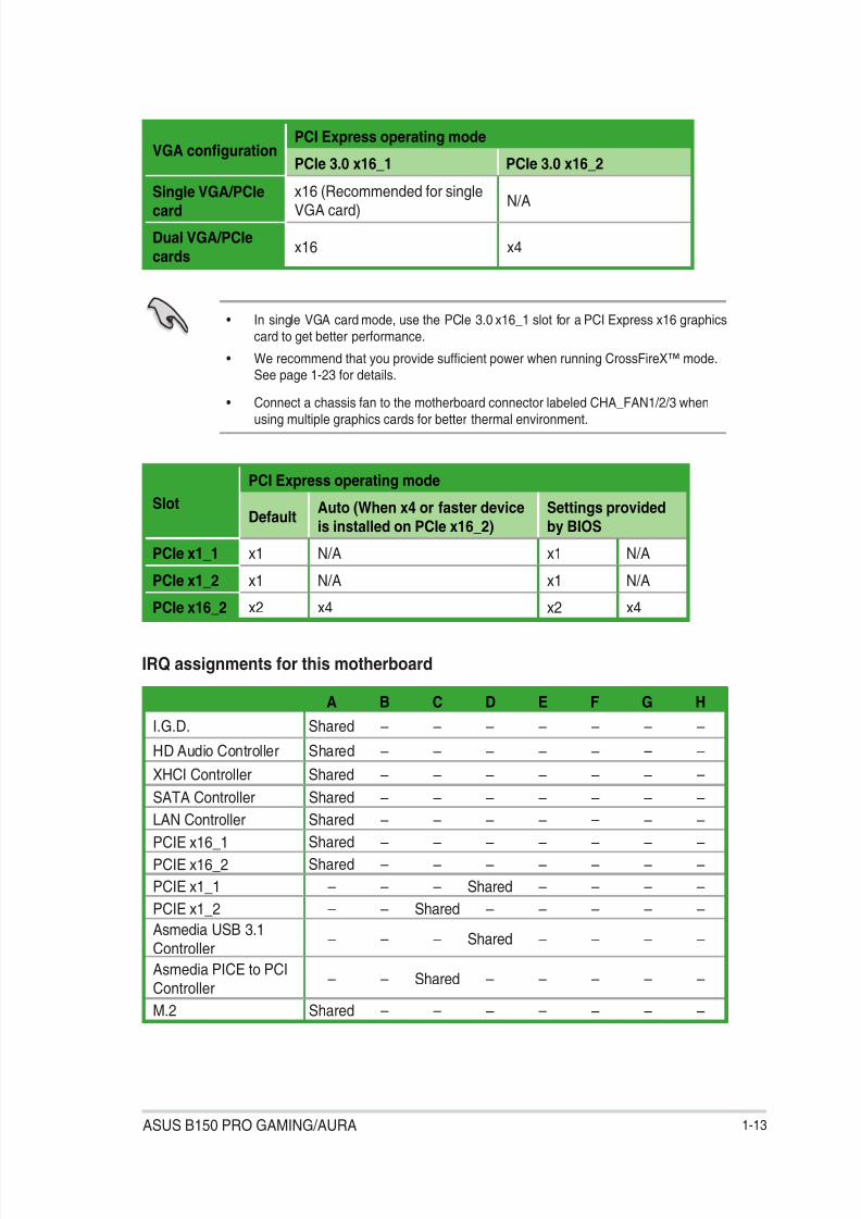
DDR4 2133 MHz capability
Vendors Part No. SizeSS/ DS
Chip Brand Chip NO. Timing VoltageDIMM socket support(Optional)
1 DIMM 2 DIMMs 4 DIMMs
SAMSUNG M378A5143DB0--CPB 4G SS SEC 428 BCPB K4A4G085WD 13-13-13-33 1.5V • • •
SAMSUNG M378A1G43DB0--CPB 8G DS SEC 428 BCPB K4A4G085WD 13-13-13-33 1.5V • • •
G.SKILL F4-2133C15Q-32GRK 8G DS N/A Heat-Sink Package 15-15-15-35 1.2V • • •
G.SKILL F4-2133C15Q-16GRB 4G SS N/A Heat-Sink Package 15-15-15-35 1.2V • • •
GLOWAY PC4-17000 4G SS N/A Heat-Sink Package 15-15-15-35 1.2V • • •
KINGSTON HX421C13PBK4/16 4G SS N/A Heat-Sink Package - 1.2V • • •
KINGSTON HX421C14FB/8 8G DS N/A Heat-Sink Package 14-14-14-35 1.2V • • •
KINGSTON HX421C14FBK4/32 8G DS N/A Heat-Sink Package - 1.2V • • •
PANRAM PUD42133C138G4NJW 8G DS N/A Heat-Sink Package 13-13-13-35 1.2V • • •
PANRAM PUD42133C134G4NJW 4G SS N/A Heat-Sink Package 13-13-13-35 1.2V • • •
CORSAIR CMK16GX4M4A2133C15 4G SS N/A Heat-Sink Package 15-15-15-36 1.2V • • •
CORSAIR CMV4GX4M1A2133C15 4G SS N/A 4GA72Z9RGR 13-13-34-33 1.5V • • •
CORSAIR CMV8GX4M1A2133C15 8G DS SEC 446 BCPB K4A4G085WD 13-13-13-33 1.5V • • •
CRUCIAL MTA8ATF51264AZ-2G1A1 4G SS MICRON 4QA77D9RCQ 13-13-13-33 1.2V • • •
TEAM TED48GM2133C15BK 8G DS SEC 437BCBP K4A4G085WD 15-15-15-36 1.2V • • •
TEAM TED44GM2133C15BK 4G SS SEC 443 BCBP K4A4G085WD 15-15-15-36 1.2V • •
APACER 78.C1GM3.AF10B 8G DS SK HYNIX H5AN4G8NMFR 14-14-14-33 1.5V • • •
APACER AU04GGB13CDTBGC 4G SS S K HYNIX H5AN4G8NMFR 14-14-14-33 1.5V • •
TEKISM T4U2133B8G15-SAD 8G DS SEC 446 BCPB K4A4G085WD - - • • •
• SS: Single-sided / DS: Double-sided
DIMM support:
• 1 DIMM: Supports one module inserted into any slot as Single-channel memoryconguration. Install the module into A2 slot for better compatibility.
• 2 DIMMs: Supports two modules inserted into the same color slots as one pair ofDual-channel memory conguration. Install the modules into A2/B2 slots
for better compatibility.
• 4 DIMMs: Supports four modules inserted into all slots as two pairs of Dual-channelmemory conguration
• Visit the ASUS website at www.asus.com for the latest QVL.
• When running XMP at DDR4 3200 MHz or higher, the system’s stability depends onthe CPU’s capabilities.
• Highly recommended to use 4-DIMM/2-DIMM kit for full DIMM conguration. FullDIMM support is subject to the physical characteristics of individual CPUs orMemory.
• Memory module with memory frequency higher than 2133 MHz and its correspondingtiming or the loaded XMP Prole is not the JEDEC memory standard. The stability andcompatibility of these memory modules depend on the CPU’s capabilities and otherinstalled devices.
• Due to Intel ® chipset limitation, DDR4 2133 MHz and faster memory modules on XMPmode will run at the maximum transfer rate of DDR4 2133 MHz.

8/17/2019 PLACA b150 Pro Gaming
http://slidepdf.com/reader/full/placa-b150-pro-gaming 19/92
ASUS B150 PRO GAMING/AURA 1-11
1.4.3 Installing a DIMM
1
2
3
To remove a DIMM
B A

8/17/2019 PLACA b150 Pro Gaming
http://slidepdf.com/reader/full/placa-b150-pro-gaming 20/92
1-12 Chapter 1: Product introduction
1.5 Expansion slotsIn the future, you may need to install expansion cards. The following sub-sections describethe slots and the expansion cards that they support.
Unplug the power cord before adding or removing expansion cards. Failure to do so may
cause you physical injury and damage motherboard components.
1.5.1 Installing an expansion card
To install an expansion card:
1. Before installing the expansion card, read the documentation that came with it andmake the necessary hardware settings for the card.
2. Remove the system unit cover (if your motherboard is already installed in a chassis).
3. Remove the bracket opposite the slot that you intend to use. Keep the screw for lateruse.
4. Align the card connector with the slot and press rmly until the card is completelyseated on the slot.
5. Secure the card to the chassis with the screw you removed earlier.
6. Replace the system cover.
1.5.2 Conguring an expansion card
After installing the expansion card, congure it by adjusting the software settings.
1. Turn on the system and change the necessary BIOS settings, if any. See Chapter 2 forinformation on BIOS setup.
2. Assign an IRQ to the card.
3. Install the software drivers for the expansion card.
When using PCI cards on shared slots, ensure that the drivers support “Share IRQ” or thatthe cards do not need IRQ assignments. Otherwise, conicts will arise between the two PCIgroups, making the system unstable and the card inoperable.
1.5.3 PCI slots
The PCI slot supports cards such as a LAN card, SCSI card, USB card, and other cards thatcomply with PCI specications.
1.5.3 PCI Express 3.0 x1 slots
This motherboard supports PCI Express x1 network cards, SCSI cards, and other cards that
comply with the PCI Express specications.
1.5.4 PCI Express 3.0 x16 slotsThis motherboard has two PCI Express 3.0 x16 slot that supports PCI Express 3.0 x16graphic cards complying with the PCI Express specications.
8/17/2019 PLACA b150 Pro Gaming
http://slidepdf.com/reader/full/placa-b150-pro-gaming 21/92
ASUS B150 PRO GAMING/AURA 1-13
• In single VGA card mode, use the PCIe 3.0 x16_1 slot for a PCI Express x16 graphicscard to get better performance.
• We recommend that you provide sufcient power when running CrossFireX™ mode.See page 1-23 for details.
• Connect a chassis fan to the motherboard connector labeled CHA_FAN1/2/3 whenusing multiple graphics cards for better thermal environment.
VGA congurationPCI Express operating mode
PCIe 3.0 x16_1 PCIe 3.0 x16_2
Single VGA/PCIecard
x16 (Recommended for singleVGA card)
N/A
Dual VGA/PCIe
cards x16 x4
Slot
PCI Express operating mode
DefaultAuto (When x4 or faster device
is installed on PCIe x16_2)
Settings provided
by BIOS
PCIe x1_1 x1 N/A x1 N/A
PCIe x1_2 x1 N/A x1 N/APCIe x16_2 x2 x4 x2 x4
IRQ assignments for this motherboard
A B C D E F G H
I.G.D. Shared – – – – – – –
HD Audio Controller Shared – – – – – – –
XHCI Controller Shared – – – – – – –SATA Controller Shared – – – – – – –
LAN Controller Shared – – – – – – –
PCIE x16_1 Shared – – – – – – –
PCIE x16_2 Shared – – – – – – –
PCIE x1_1 – – – Shared – – – –
PCIE x1_2 – – Shared – – – – –
Asmedia USB 3.1Controller
– – – Shared – – – –
Asmedia PICE to PCIController
– – Shared – – – – –
M.2 Shared – – – – – – –

8/17/2019 PLACA b150 Pro Gaming
http://slidepdf.com/reader/full/placa-b150-pro-gaming 22/92
1-14 Chapter 1: Product introduction
1.6 Jumpers1. Clear RTC RAM (2-pin CLRTC)
This header allows you to clear the Real Time Clock (RTC) RAM in CMOS. You canclear the CMOS memory of date, time, and system setup parameters by erasing theCMOS RTC RAM data. The onboard button cell battery powers the RAM data in
CMOS, which include system setup information such as system passwords.
To erase the RTC RAM:
1. Turn OFF the computer and unplug the power cord.
2. Use a metal object such as a screwdriver to short the two pins.
3. Plug the power cord and turn ON the computer.
4. Hold down the <Del> key during the boot process and enter BIOS setup to re-enter data.
• If the steps above do not help, remove the onboard battery and short the two pinsagain to clear the CMOS RTC RAM data. After clearing the CMOS, reinstall thebattery.
• You do not need to clear the RTC when the system hangs due to overclocking. Forsystem failure due to overclocking, use the CPU Parameter Recall (C.P.R.) feature.Shut down and reboot the system, then the BIOS automatically resets parametersettings to default values.
B150 PRO GAMING/AURA Clear RTC RAM
CLRTC
+ 3 V_
B A T
G N D
PIN 1
8/17/2019 PLACA b150 Pro Gaming
http://slidepdf.com/reader/full/placa-b150-pro-gaming 23/92
ASUS B150 PRO GAMING/AURA 1-15
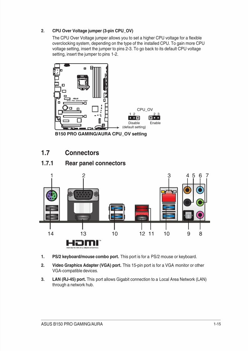
2. CPU Over Voltage jumper (3-pin CPU_OV)
The CPU Over Voltage jumper allows you to set a higher CPU voltage for a exibleoverclocking system, depending on the type of the installed CPU. To gain more CPUvoltage setting, insert the jumper to pins 2-3. To go back to its default CPU voltage
setting, insert the jumper to pins 1-2.
1.7 Connectors
1.7.1 Rear panel connectors
2 43 5 6 7
8913 10 1012 11
1
14
1. PS/2 keyboard/mouse combo port. This port is for a PS/2 mouse or keyboard.
2. Video Graphics Adapter (VGA) port. This 15-pin port is for a VGA monitor or otherVGA-compatible devices.
3. LAN (RJ-45) port. This port allows Gigabit connection to a Local Area Network (LAN)through a network hub.
B150 PRO GAMING/AURA CPU_OV setting
21 32
Disable(default setting)
Enable
CPU_OV

8/17/2019 PLACA b150 Pro Gaming
http://slidepdf.com/reader/full/placa-b150-pro-gaming 24/92
1-16 Chapter 1: Product introduction
LAN port
SpeedLED
Activity LinkLED
LAN port LED indications
4. Center / Subwoofer port (orange). This port connects the center/subwoofer speakers.
5. Rear Speaker Out port (black). This port connects the rear speakers in a 4.1 channel,5.1 channel, or 7.1 channel audio conguration.
6. Line In port (light blue). This port connects to the tape, CD, DVD player, or otheraudio sources.
7. Line Out port (lime). This port connects to a headphone or a speaker. In the 4.1, 5.1,and 7.1 channel congurations, the function of this port becomes Front Speaker Out.
8. Microphone port (pink). This port connects to a microphone.
Activity/Link LED Speed LED
Status Description Status Description
Off No link OFF 10 Mbps connectionOrange Linked ORANGE 100 Mbps connection
Orange
(Blinking)
Data activity GREEN 1 Gbps connection
Orange (Blinking
then steady)
Ready to wake
up from S5 mode
Port Headset2-channel
4.1-channel 5.1-channel 7.1-channel
Light Blue Line In Line In Line In Line In
Lime Line Out Front Speaker Out Front Speaker Out Front Speaker Out
Pink Mic In Mic In Mic In Mic In
Orange – – Center/Subwoofer Center/Subwoofer
Optical S/ PDIF out
– – – Side Speaker Out
Black – Rear Speaker Out Rear Speaker Out Rear Speaker Out
Audio 2, 4.1, 5.1, or 7.1-channel conguration
9. Optical S/PDIF out port. This port allows you to connect your PC to amplied
speakers, headphones, or Sony/Phillips Digital Interconnect Format (S/PDIF) compliantdevices.
10. USB 3.0 ports. These 9-pin Universal Serial Bus (USB) ports are for USB 3.0 devices.
• USB 3.0 devices can only be used for data storage.
• We strongly recommend that you connect USB 3.0 devices to USB 3.0 ports for fasterand better performance from your USB 3.0 devices.
• Due to the design of the Intel ® 100 series chipset, all USB devices connected to theUSB 2.0 and USB 3.0 ports are controlled by the xHCI controller. Some legacy USBdevices must update their rmware for better compatibility.

8/17/2019 PLACA b150 Pro Gaming
http://slidepdf.com/reader/full/placa-b150-pro-gaming 25/92
ASUS B150 PRO GAMING/AURA 1-17
11. USB 3.1 Type A port. This 9-pin Universal Serial Bus (USB) Type A port is for USB3.1 devices.
12. USB 3.1 Type C port. This Universal Serial Bus (USB) Type C port is for USB 3.1mobile or peripheral devices.
13. HDMI port. This port is for a High-Denition Multimedia Interface (HDMI) connector,and is HDCP compliant allowing playback of HD DVD, Blu-ray, and other protectedcontent.
14. USB 2.0 ports. These 4-pin Universal Serial Bus (USB) ports are for USB 2.0/1.1devices.
1.7.2 Internal connectors
1. Serial port connector (10-1 pin COM)
This connector is for a serial (COM) port. Connect the serial port module cable to this
connector, then install the module to a slot opening at the back of the system chassis.
The COM module is purchased separately.
B150 PRO GAMING/AURA Serial port (COM) connector
PIN 1
COM
D C D
T X D
G N D
R T S R
I
R X D
D T R
D S R
C T S
8/17/2019 PLACA b150 Pro Gaming
http://slidepdf.com/reader/full/placa-b150-pro-gaming 26/92
1-18 Chapter 1: Product introduction
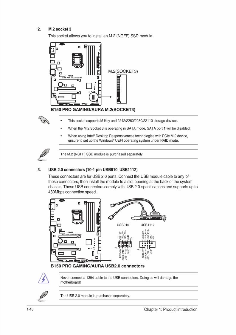
2. M.2 socket 3
This socket allows you to install an M.2 (NGFF) SSD module.
• This socket supports M Key and 2242/2260/2280/22110 storage devices.
• When the M.2 Socket 3 is operating in SATA mode, SATA port 1 will be disabled.
• When using Intel ® Desktop Responsiveness technologies with PCIe M.2 device,ensure to set up the Windows ® UEFI operating system under RAID mode.
The M.2 (NGFF) SSD module is purchased separately
B150 PRO GAMING/AURA M.2(SOCKET3)
M.2(SOCKET3)
3. USB 2.0 connectors (10-1 pin USB910, USB1112)
These connectors are for USB 2.0 ports. Connect the USB module cable to any ofthese connectors, then install the module to a slot opening at the back of the systemchassis. These USB connectors comply with USB 2.0 specications and supports up to480Mbps connection speed.
Never connect a 1394 cable to the USB connectors. Doing so will damage themotherboard!
The USB 2.0 module is purchased separately.
B150 PRO GAMING/AURA USB2.0 connectors
U S B + 5 V
U S B_
P 1 1 -
U S B_
P 1 1 +
G N D
N C
U S B + 5 V
U S B_
P 1 2 -
U S B_
P 1 2 +
G N D
USB1112
PIN 1
PIN 1
U S B + 5 V
U S B_
P 9 -
U S B_
P 9 +
G N D
N C
U S B + 5 V
U S B_
P 1 0 -
U S B_
P 1 0 +
G N D
USB910

8/17/2019 PLACA b150 Pro Gaming
http://slidepdf.com/reader/full/placa-b150-pro-gaming 27/92
ASUS B150 PRO GAMING/AURA 1-19
4. CPU, water pump, and chassis fan connectors (4-pin CPU_FAN; 4-pin W_PUMP;
4-pin CHA_FAN1~3)
Connect the fan cables to the fan connectors on the motherboard, ensuring that theblack wire of each cable matches the ground pin of the connector.
• Do not forget to connect the fan cables to the fan connectors. Insufcient air owinside the system may damage the motherboard components. These are not jumpers!
Do not place jumper caps on the fan connectors!
• Ensure that the CPU fan cable is securely installed to the CPU fan connector.
• The CPU_FAN connector supports a CPU fan of maximum 1 A (12 W) fan power.
• W_PUMP function support depends on water cooling device.
• The CPU_FAN connector and CHA_FAN connectors support the ASUS FAN Xpert 3feature.
• The CPU fan connector detects the type of CPU fan installed and automaticallyswitches the control modes. To congure the CPU fan’s control mode, go toAdvanced > Monitor > Q-Fan Conguration > CPU Q-Fan Control item in BIOS.
• The chassis fan connectors support DC and PWM modes. To set these fans to DCor PWM, go to Advanced > Monitor > Q-Fan Conguration > Chassis Fan 1/2/3Q-Fan Control items in BIOS.
CHA_FAN1
CHA_FAN3
C H A F A N P W M
C H A F A N I N
C H A F A N P W R
G N D
C H A F A N P W M
C H A F A N I N
C H A F A N P W R
G N D
A
D
E
D E
W_PUMPCPU_FAN
C P U F A N P W M
C P U F A N I N
C P U F A N P W R
G N D
P U M P P W M
P U M P I N
P U M P P W R
G N D
BA
CHA_FAN2
GND
CHA FAN PWR
CHA FAN IN
CHA FAN PWM
C
B
C
B150 PRO GAMING/AURA Fan connectors

8/17/2019 PLACA b150 Pro Gaming
http://slidepdf.com/reader/full/placa-b150-pro-gaming 28/92
1-20 Chapter 1: Product introduction
• For a fully congured system, we recommend that you use a power supply unit(PSU) that complies with ATX 12 V Specication 2.0 (or later version) and provides aminimum power of 350 W.
• DO NOT forget to connect the 4-pin/8-pin ATX +12V power plug. Otherwise, the
system will not boot up.• We recommend that you use a PSU with higher power output when conguring a
system with more power-consuming devices or when you intend to install additionaldevices. The system may become unstable or may not boot up if the power isinadequate.
• If you are uncertain about the minimum power supply requirement for your system,refer to the Recommended Power Supply Wattage Calculator at http://support.asus.com/PowerSupplyCalculator/PSCalculator.aspx?SLanguage=en-us for details.
5. ATX power connectors (24-pin EATXPWR, 8-pin ATX12V)
These connectors are for ATX power supply plugs. The power supply plugs aredesigned to t these connectors in only one orientation. Find the proper orientation andpush down rmly until the connectors completely t.
6. Thermal sensor connector (2-pin T_SENSOR)
This connector is for the thermistor cable that allows you to monitor the temperature ofyour motherboard’s critical components and connected devices.
B150 PRO GAMING/AURA ATX power connectors
EATX12V
+ 1 2 V
D C
+ 1 2 V
D C
+ 1 2 V
D C
+ 1 2 V
D C
G N D
G N D
G N D
G N D
EATXPWR
PIN 1
PIN 1
GND+5 Volts
+5 Volts
+5 Volts
-5 VoltsGND
GND
GNDPSON#
GND
-12 Volts+3 Volts
+3 Volts
+12 Volts
+12 Volts+5V Standby
Power OK
GND+5 Volts
GND
+5 VoltsGND
+3 Volts
+3 Volts
AA B
B
PIN 1
T_SENSOR
SENSOR IN
GND
B150 PRO GAMING/AURA T_SENSOR connector

8/17/2019 PLACA b150 Pro Gaming
http://slidepdf.com/reader/full/placa-b150-pro-gaming 29/92
ASUS B150 PRO GAMING/AURA 1-21
7. Front panel audio connector (10-1 pin AAFP)
This connector is for a chassis-mounted front panel audio I/O module that supports HDAudio audio standard. Connect one end of the front panel audio I/O module cable tothis connector.
• We recommend that you connect a high-denition front panel audio module to thisconnector to avail of the motherboard’s high-denition audio capability.
• If you want to connect a high-denition front panel audio module to this connector, setthe Front Panel Type item in the BIOS setup to [HD Audio]. By default, this connectoris set to [HD Audio]. See section 2.6.7 Onboard Devices Conguration for details.
8. ROG Extension - ROG_EXT connector (18-1 pin ROG_EXT)
This connector is for the Front Base.
• The Front Base is purchased separately.
• Visit www.asus.com for more information about the Front Base.
B150 PRO GAMING/AURA Front panel audio connector
AAFP
A G N D
N C S E N S E 1_
R E T U R
S E N S E 2_
R E T U R
P O R T 1 L
P O R T 1 R
P O R T 2 R
S E
N S E_
S E N D
P O R T 2 L
HD-audio-compliant
pin definition
B150 PRO GAMING/AURA ROG_EXT connectors
ROG_EXT

8/17/2019 PLACA b150 Pro Gaming
http://slidepdf.com/reader/full/placa-b150-pro-gaming 30/92
1-22 Chapter 1: Product introduction
9. USB 3.0 connector (20-1 pin USB3_12)
This connector allows you to connect a USB 3.0 module for additional USB 3.0 frontor rear panel ports. With an installed USB 3.0 module, you can enjoy all the benets ofUSB 3.0 including faster data transfer speeds of up to 5 Gbps, faster charging time for
USB-chargeable devices, optimized power efciency, and backward compatibility withUSB 2.0.
The USB 3.0 module is purchased separately.
• These connectors are based on xHCI specication. We recommend you to install therelated driver to fully use the USB 3.0 ports under Windows ® 7.
• The plugged USB 3.0 device will run on xHCI mode.
• These USB 3.0 ports support native UASP transfer standard in Windows ® 8 /Windows ® 8.1 and Turbo Mode when using USB 3.0 Boost feature.
B150 PRO GAMING/AURA USB3.0 Front panel connector
USB3_12
USB3+5V
IntA_P1_SSRX-
IntA_P1_SSRX+
GND
IntA_P1_SSTX-
IntA_P1_SSTX+
GNDIntA_P1_D-
IntA_P1_D+
GND
PIN 1
USB3+5V
IntA_P2_SSRX-
IntA_P2_SSRX+
GND
IntA_P2_SSTX-
IntA_P2_SSTX+GND
IntA_P2_D-
IntA_P2_D+
10. TPM connector (14-1 pin TPM)
This connector supports a Trusted Platform Module (TPM) system, which securely
store keys, digital certicates, passwords and data. A TPM system also helps enhancethe network security, protects digital identities, and ensures platform integrity.
TPM
B150 PRO GAMING/AURA TPM connector
PIN 1
+ 3 V S B
S_
P C I R S T #_
T B D
G N D
C_
P C I C L K_
T P M + 3 V
+ 3 V
F_
C L K R U N
F_
S E R I R Q
F_
F R A M E #
F_
L A D 3
F_
L A D 2
F_
L A D 1
F_
L A D 0
8/17/2019 PLACA b150 Pro Gaming
http://slidepdf.com/reader/full/placa-b150-pro-gaming 31/92
ASUS B150 PRO GAMING/AURA 1-23
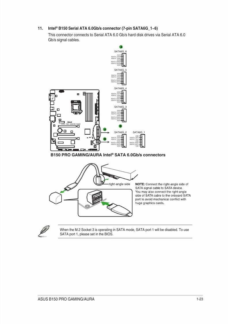
11. Intel ® B150 Serial ATA 6.0Gb/s connector (7-pin SATA6G_1~6)
This connector connects to Serial ATA 6.0 Gb/s hard disk drives via Serial ATA 6.0
Gb/s signal cables.
A
A
B
B
SATA6G_2
GND
RSATA_TXP2
RSATA_TXN2
GND
RSATA_RXN2
RSATA_RXP2
GND
SATA6G_3
GND
RSATA_TXP3
RSATA_TXN3
GND
RSATA_RXN3
RSATA_RXP3
GND
SATA6G_4
GND
RSATA_TXP4
RSATA_TXN4
GND
RSATA_RXN4
RSATA_RXP4
GND
SATA6G_5
GND
RSATA_TXP5
RSATA_TXN5
GND
RSATA_RXN5
RSATA_RXP5
GND
SATA6G_6GND
RSATA_TXP6
RSATA_TXN6
GND
RSATA_RXN6
RSATA_RXP6
GND
SATA6G_1
GND
RSATA_TXP1
RSATA_TXN1
GND
RSATA_RXN1
RSATA_RXP1
GND
B150 PRO GAMING/AURA
Intel ®
SATA 6.0Gb/s connectors
When the M.2 Socket 3 is operating in SATA mode, SATA port 1 will be disabled. To useSATA port 1, please set in the BIOS.
8/17/2019 PLACA b150 Pro Gaming
http://slidepdf.com/reader/full/placa-b150-pro-gaming 32/92
1-24 Chapter 1: Product introduction
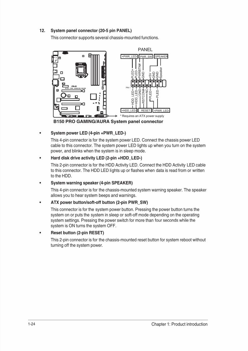
• System power LED (4-pin +PWR_LED-)
This 4-pin connector is for the system power LED. Connect the chassis power LEDcable to this connector. The system power LED lights up when you turn on the systempower, and blinks when the system is in sleep mode.
• Hard disk drive activity LED (2-pin +HDD_LED-)
This 2-pin connector is for the HDD Activity LED. Connect the HDD Activity LED cableto this connector. The HDD LED lights up or ashes when data is read from or writtento the HDD.
• System warning speaker (4-pin SPEAKER)
This 4-pin connector is for the chassis-mounted system warning speaker. The speakerallows you to hear system beeps and warnings.
• ATX power button/soft-off button (2-pin PWR_SW)
This connector is for the system power button. Pressing the power button turns thesystem on or puts the system in sleep or soft-off mode depending on the operatingsystem settings. Pressing the power switch for more than four seconds while the
system is ON turns the system OFF.
• Reset button (2-pin RESET)
This 2-pin connector is for the chassis-mounted reset button for system reboot withoutturning off the system power.
12. System panel connector (20-5 pin PANEL)
This connector supports several chassis-mounted functions.
B150 PRO GAMING/AURA System panel connector
P L E D +
P L E D -
P W R B T N #
G N D
+ 5 V G N D
G N D
S p e a k e r
H D D_
L E D +
H D D_
L E D -
G N D
R S T C O N # N C
P L E D +
P L E D -
PIN 1
+PWR_LED-
+PWR_LED-
SPEAKER
PANEL
+HDD_LED-
PWR_SW
RESET
* Requires an ATX power supply

8/17/2019 PLACA b150 Pro Gaming
http://slidepdf.com/reader/full/placa-b150-pro-gaming 33/92
ASUS B150 PRO GAMING/AURA 1-25
1.8 Onboard LED
1. Standby Power LED (SB_PWR)
The motherboard comes with a standby power LED that lights up to indicate that thesystem is ON, in sleep mode, or in soft-off mode. This is a reminder that you shouldshut down the system and unplug the power cable before removing or plugging in anymotherboard component. The illustration below shows the location of the onboard LED.
B150 PRO GAMING/AURA Standby power LED
SB_PWR
ONStandby Power Powered Off
OFF
2. SupremeFX LED
The SupremeFX LED lights up in the following three ways to bring you an ultimatelighting effect. This LED also outlines the separation of the audio components from the
rest of your motherboard.
Lit mode Description
Breathing mode The LED blinks intermittently.
Flowing mode The LED lights up and dims like owing water.
Still mode The LED becomes solid red.
You can turn off the SupremeFX LED or change the lit modes from the BIOS or the LEDControl app named Aura. To change the setting in BIOS, go to Advanced > OnboardDevices Conguration > SupremeFX LED Lighting item. See section 2.6.7 OnboardDevices Conguration for details.
B150 PRO GAMING/AURA SupremeFX LED Lighting
SupremeFX LED

8/17/2019 PLACA b150 Pro Gaming
http://slidepdf.com/reader/full/placa-b150-pro-gaming 34/92
1-26 Chapter 1: Product introduction
B150 PRO GAMING/AURA CPU/DRAM/
BOOT_DEVICE/VGA LED
CPU_LED
DRAM_LED
VGA_LED
BOOT_DEVICE_LED
3. Q LEDs (BOOT_DEVICE_LED, VGA_LED, DRAM_LED, CPU_LED)
Q LEDs check key components (CPU, DRAM, VGA card, and booting devices) insequence during motherboard booting process. If an error is found, the correspondingLED remains lit until the problem is solved. This user-friendly design provides an
intuitive way to locate the root problem within seconds.
4. RGB LED
The RGB LED lighting control provides several lighting schemes, which allow youto customize your favorite LED effect. You can set your favorite LED effect to casta stunning multi-color glow across your build, change shades to indicate CPUtemperature, or pulsate in time to the beat of your music.
B150 PRO GAMING/AURA RGB LED Lighting
RGB LED
You can change the lighting schemes from the LED Control app named Aura.
8/17/2019 PLACA b150 Pro Gaming
http://slidepdf.com/reader/full/placa-b150-pro-gaming 35/92
ASUS B150 PRO GAMING/AURA 1-27
1.9 Software support
1.9.1 Installing an operating system
This motherboard supports Windows ® 7 (32-bit / 64-bit), Windows ® 8.1 (64-bit) and Windows ®
10 (64-bit) Operating Systems (OS). Always install the latest OS version and correspondingupdates to maximize the features of your hardware.
Motherboard settings and hardware options vary. Refer to your OS documentation fordetailed information.
1.9.2 Support DVD information
The Support DVD that comes with the motherboard package contains the drivers, software
applications, and utilities that you can install to avail all motherboard features.
The contents of the Support DVD are subject to change at any time without notice. Visit theASUS website at www.asus.com for updates.
The following screen is for reference only.
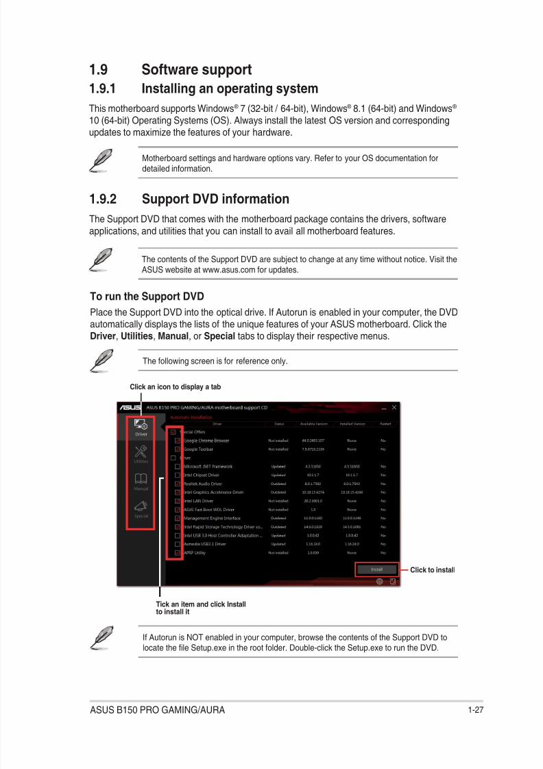
To run the Support DVD
Place the Support DVD into the optical drive. If Autorun is enabled in your computer, the DVDautomatically displays the lists of the unique features of your ASUS motherboard. Click theDriver, Utilities, Manual, or Special tabs to display their respective menus.
If Autorun is NOT enabled in your computer, browse the contents of the Support DVD tolocate the le Setup.exe in the root folder. Double-click the Setup.exe to run the DVD.
Click an icon to display a tab
Tick an item and click Install
to install it
Click to install

8/17/2019 PLACA b150 Pro Gaming
http://slidepdf.com/reader/full/placa-b150-pro-gaming 36/92
1-28 Chapter 1: Product introduction

8/17/2019 PLACA b150 Pro Gaming
http://slidepdf.com/reader/full/placa-b150-pro-gaming 37/92
2.1 Managing and updating your BIOS
Save a copy of the original motherboard BIOS le to a USB ash disk in case you needto restore the BIOS in the future. Copy the original motherboard BIOS using the ASUS
Update utility.
2.1.1 EZ Update
EZ Update is a utility that allows you to automatically update your motherboard’s softwares,
drivers and the BIOS version easily. With this utlity, you can also manually update the savedBIOS and select a boot logo when the system goes into POST.
To launch EZ Update, click EZ Update on the AI Suite 3 main menu bar.
BIOS information 2
EZ Update requires an Internet connection either through a network or an ISP (InternetService Provider).
Click to automaticallyupdate your
motherboard’s driver,software and rmware
Click to nd and
select the BIOSfrom le
Click to selecta boot logo
Click to updatethe BIOS
ASUS B150 PRO GAMING/AURA 2-1

8/17/2019 PLACA b150 Pro Gaming
http://slidepdf.com/reader/full/placa-b150-pro-gaming 38/92
2.1.2 ASUS EZ Flash 3
The ASUS EZ Flash 3 feature allows you to update the BIOS without using an OS‑basedutility.
• Ensure that you load the BIOS default settings to ensure system compatibility andstability. Select the Load Optimized Defaults item under the Exit menu. See section2.10 Exit Menu for details.
• Check your Internet connection before updating the BIOS via the Internet.
To update the BIOS using EZ Flash 3:
1. Enter the Advanced Mode of the BIOS setup program. Go to the Tool menu to selectASUS EZ Flash 3 Utility and press <Enter> to enable it.
2. Follow the steps below to update the BIOS via a storage device or Internet.
Via Storage Device
a) Insert the USB ash disk that contains the latest BIOS le to the USB port, thenselect via Storage Device.
b) Press <Tab> to switch to the Drive eld.
c) Press the Up/Down arrow keys to nd the USB ash disk that contains the latestBIOS, and then press <Enter>.
d) Press <Tab> to switch to the Folder Info eld.
e) Press the Up/Down arrow keys to nd the BIOS le, and then press <Enter> toperform the BIOS update process.
Via Internet
a) Select via Internet.
b) Press the Left/Right arrow keys to select an Internet connection method, and thenpress <Enter>.
c) Follow the onscreen instructions to complete the update.
3. Reboot the system when the update process is done.
• ASUS EZ Flash 3 supports USB devices, such as a USB ash disk, with FAT 32/16format and single partition only.
• DO NOT shut down or reset the system while updating the BIOS to prevent systemboot failure!
2-2 Chapter 2: Getting started
8/17/2019 PLACA b150 Pro Gaming
http://slidepdf.com/reader/full/placa-b150-pro-gaming 39/92
2.1.3 ASUS CrashFree BIOS 3 utility
The ASUS CrashFree BIOS 3 is an auto recovery tool that allows you to restore the BIOS lewhen it fails or gets corrupted during the updating process. You can restore a corrupted BIOS
le using the motherboard support DVD or a USB ash drive that contains the updated BIOS
le.
• Before using this utility, rename the BIOS le in the removable device into B5PGA.CAP.
• The BIOS le in the support DVD may not be the latest version. Download the latestBIOS le from the ASUS website at www.asus.com.
Recovering the BIOS
To recover the BIOS:
1. Turn on the system.
2. Insert the support DVD to the optical drive or the USB ash drive that contains theBIOS le to the USB port.
3. The utility automatically checks the devices for the BIOS le. When found, the utilityreads the BIOS le and enters ASUS EZ Flash 3 utility automatically.
4. The system requires you to enter BIOS Setup to recover BIOS settings. To ensuresystem compatibility and stability, we recommend that you press <F5> to load defaultBIOS values.
DO NOT shut down or reset the system while updating the BIOS! Doing so can causesystem boot failure!
2.1.4 ASUS BIOS Updater
ASUS BIOS Updater allows you to update the BIOS in DOS environment.
The screen captures used in this section are for reference only and may not be exactly thesame as actually shown on your computer screen.
Before updating BIOS
• Prepare the motherboard support DVD and a USB ash drive.
• Download the latest BIOS le and BIOS Updater from http://support.asus.com and
save them in your USB ash drive.
NTFS is not supported under FreeDOS environment. Ensure that your USB ash drive is insingle partition and in FAT32/16 format.
• Turn off the computer.• Ensure that your computer has a DVD optical drive.
ASUS B150 PRO GAMING/AURA 2‑3

8/17/2019 PLACA b150 Pro Gaming
http://slidepdf.com/reader/full/placa-b150-pro-gaming 40/92
Booting the system in DOS environment
To boot the system in DOS:
1. Insert the USB ash drive with the latest BIOS le and BIOS Updater to the USB port.
2. Boot your computer then press <F8> to launch the select boot device screen.
3. When the select boot device screen appears, insert the Support DVD into the opticaldrive then select the optical drive as the boot device.
Please select boot device:
and to move selection
ENTER to select boot device
ESC to boot using defaults
P2: ST3808110AS (76319MB)
aigo miniking (250MB)
UEFI: (FAT) ASUS DRW-2014L1T(4458MB)
P1: ASUS DRW-2014L1T(4458MB)
UEFI: (FAT) aigo miniking (250MB)
Enter Setup
4. When the booting message appears, press <Enter> within ve (5) seconds to enterFreeDOS prompt.
Welcome to FreeDOS (http://www.freedos.org)!
C:/> d:
D:/>
5. On the FreeDOS prompt, type d: then press <Enter> to switch the disk from Drive C(optical drive) to Drive D (USB ash drive).
ISOLINUX 3.20 2006-08-26 Copyright (C) 1994-2005 H. Peter Anvin
A Bootable DVD/CD is detected. Press ENTER to boot from the DVD/CD.If no key is pressed within 5 seconds, the system will boot next priority
device automatically. boot:
Updating the BIOS le
To update the BIOS le:
1. On the FreeDOS prompt, type bupdater /pc /g and press <Enter>.
2. On the BIOS Updater screen, press <Tab> to switch from Files panel to Drives panelthen select D:.
D:/> bupdater /pc /g
2-4 Chapter 2: Getting started

8/17/2019 PLACA b150 Pro Gaming
http://slidepdf.com/reader/full/placa-b150-pro-gaming 41/92
ASUSTeK BIOS Updater for DOS V1.30 [2014/01/01]
Current ROM BOARD: B150 PRO GAMING AURA
VER: 0204 (H :00 B :00)
DATE: 09/24/2015
Update ROM BOARD: Unknown
VER: Unknown
DATE: Unknown
PATH: C:\
C:
D:
FORMAN~1 <DIR>
B5PGA.CAP 16779264 2015-09-24 21:14:34
Note
[Enter] Select or Load [Tab] Switch [V] Drive Info[Up/Down/Home/End] Move [Esc] Exit
Filespanel
Drivespanel
3. Press <Tab> to switch from Drives panel to Files panel then press <Up/Down or Home/ End> keys to select the BIOS le and press <Enter>.
4. After the BIOS Updater checks the selected BIOS le, select Yes to conrm the BIOSupdate.
Are you sure you want to update the BIOS?
Yes No
The BIOS Backup feature is not supported due to security regulations.
5. Select Yes then press <Enter>. When BIOS update is done, press <ESC> to exit BIOSUpdater.
6. Restart your computer.
DO NOT shut down or reset the system while updating the BIOS to prevent system bootfailaure.
Ensure to load the BIOS default settings to ensure system compatibility and stability. Selectthe Load Optimized Defaults item under the Exit BIOS menu. See section 2.10 ExitMenu for details.
ASUS B150 PRO GAMING/AURA 2‑5

8/17/2019 PLACA b150 Pro Gaming
http://slidepdf.com/reader/full/placa-b150-pro-gaming 42/92
2.2 BIOS setup programUse the BIOS Setup program to update the BIOS or congure its parameters. The BIOSscreens include navigation keys and brief online help to guide you in using the BIOS Setupprogram.
Entering BIOS Setup at startupTo enter BIOS Setup at startup:
Press <Delete> or <F2> during the Power‑On Self Test (POST). If you do not press <Delete>or <F2>, POST continues with its routines.
Entering BIOS Setup after POST
To enter BIOS Setup after POST:
Press <Ctrl>+<Alt>+<Del> simultaneously.
Press the reset button on the system chassis.
Press the power button to turn the system off then back on. Do this option only if you failed toenter BIOS Setup using the rst two options.
Using the power button, reset button, or the <Ctrl>+<Alt>+<Del> keys to force reset from arunning operating system can cause damage to your data or system. We recommend youalways shut down the system properly from the operating system.
• The BIOS setup screens shown in this section are for reference purposes only, andmay not exactly match what you see on your screen.
• Visit the ASUS website at www.asus.com to download the latest BIOS le for thismotherboard.
• Ensure that a mouse is connected to your motherboard if you want to use the mouseto control the BIOS setup program.
• If the system becomes unstable after changing any BIOS setting, load the defaultsettings to ensure system compatibility and stability. Select the Load OptimizedDefaults item under the Exit menu or press hotkey F5. See section 2.10 Exit Menu for details.
• If the system fails to boot after changing any BIOS setting, try to clear the CMOS andreset the motherboard to the default value. See section 1.6 Headers for informationon how to erase the RTC RAM.
BIOS menu screen
The BIOS setup program can be used under two modes: EZ Mode and Advanced Mode.Press <F7> to change between the two modes.
2‑6 Chapter 2: Getting started

8/17/2019 PLACA b150 Pro Gaming
http://slidepdf.com/reader/full/placa-b150-pro-gaming 43/92
2.2.1 EZ Mode
By default, the EZ Mode screen appears when you enter the BIOS setup program. The EZMode provides you an overview of the basic system information, and allows you to select thedisplay language, system performance mode, fan prole and boot device priority. To access
the Advanced Mode, click Advanced Mode(F7) or press <F7>.
The default screen for entering the BIOS setup program can be changed. Refer to theSetup Mode item in section 2.8 Boot menu for details.
The boot device options vary depending on the devices you installed to the system.
Saves the changesand resets the
system
Selects the displaylanguage of the BIOS
setup program
Displays the CPU/motherboardtemperature, CPU voltage output,CPU/chassis fan speed, and SATAinformation
Displays the system properties ofthe selected mode. Click <Enter> to
switch EZ System Tuning modes
Displays theAdvanced mode
menus
Selects the boot
device priority
Loads optimized
default settings
Shows thebootabledevices
Displays the CPU Fan’s speed.Click the button to manually
tune the fans Search on FAQs
ASUS B150 PRO GAMING/AURA 2‑7
8/17/2019 PLACA b150 Pro Gaming
http://slidepdf.com/reader/full/placa-b150-pro-gaming 44/92
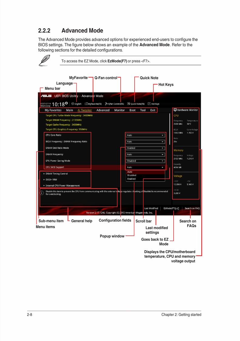
Conguration elds
Menu bar
General helpSub-menu item
Menu items
Scroll bar
Last modied
settings
Language Hot Keys
MyFavorite Q-Fan control
Goes back to EZMode
Search onFAQs
Displays the CPU/motherboardtemperature, CPU and memory
voltage output
Quick Note
2.2.2 Advanced Mode
The Advanced Mode provides advanced options for experienced end‑users to congure the
BIOS settings. The gure below shows an example of the Advanced Mode. Refer to thefollowing sections for the detailed congurations.
To access the EZ Mode, click EzMode(F7) or press <F7>.
Popup window
2‑8 Chapter 2: Getting started
8/17/2019 PLACA b150 Pro Gaming
http://slidepdf.com/reader/full/placa-b150-pro-gaming 45/92
Menu items
The highlighted item on the menu bar displays the specic items for that menu. For example,selecting Main shows the Main menu items.
The other items (My Favorites, Ai Tweaker, Advanced, Monitor, Boot, Tool, and Exit) on themenu bar have their respective menu items.
Submenu items
A greater than sign (>) before each item on any menu screen means that the item has asubmenu. To display the submenu, select the item and press <Enter>.
Language
This button above the menu bar contains the languages that you can select for your BIOS.Click this button to select the language that you want to display in your BIOS screen.
MyFavorites (F3)
This button above the menu bar shows all BIOS items in a Tree Map setup. Select frequently‑used BIOS settings and save it to MyFavorites menu.
Refer to section 2.3 My Favorites for more information.
Q-Fan Control (F6)This button above the menu bar displays the current settings of your fans. Use this button tomanually tweak the fans to your desired settings.
Refer to section 2.2.3 QFan Control for more information.
Quick Note (F9)
This button above the menu bar allows you to key in notes of the activities that you havedone in BIOS.
• The Quick Note function does not support the following keyboard functions: delete,cut, copy and paste.
• You can only use the alphanumeric characters to enter your notes.
Menu bar
The menu bar on top of the screen has the following main items:
My Favorites For saving the frequently‑used system settings and conguration
Main For changing the basic system congurationAi Tweaker For changing the overclocking settings
Advanced For changing the advanced system settings
Monitor For displaying the system temperature, power status, and changing the fan settings
Boot For changing the system boot conguration
Tool For conguring options for special functions
Exit For selecting the exit options and loading default settings
ASUS B150 PRO GAMING/AURA 2-9
8/17/2019 PLACA b150 Pro Gaming
http://slidepdf.com/reader/full/placa-b150-pro-gaming 46/92
Hot keys
This button above the menu bar contains the navigation keys for the BIOS setup program.Use the navigation keys to select items in the menu and change the settings.
Search on FAQ
Move your mouse over this button to show a QR code. Scan this QR code with your mobiledevice to connect to the ASUS BIOS FAQ web page. You can also scan the QR code below.
Scroll bar
A scroll bar appears on the right side of a menu screen when there are items that do not ton the screen. Press the Up/Down arrow keys or <Page Up> / <Page Down> keys to displaythe other items on the screen.
General help
At the bottom left corner of the menu screen is a brief description of the selected item. Use<F12> key to capture the BIOS screen and save it to the removable storage device.
Conguration elds
These elds show the values for the menu items. If an item is user‑congurable, you canchange the value of the eld opposite the item. You cannot select an item that is notuser‑congurable.
A congurable eld is highlighted when selected. To change the value of a eld, select it andpress <Enter> to display a list of options.
Last Modied button
This button shows the items that you last modied and saved in BIOS Setup.
2-10 Chapter 2: Getting started
8/17/2019 PLACA b150 Pro Gaming
http://slidepdf.com/reader/full/placa-b150-pro-gaming 47/92
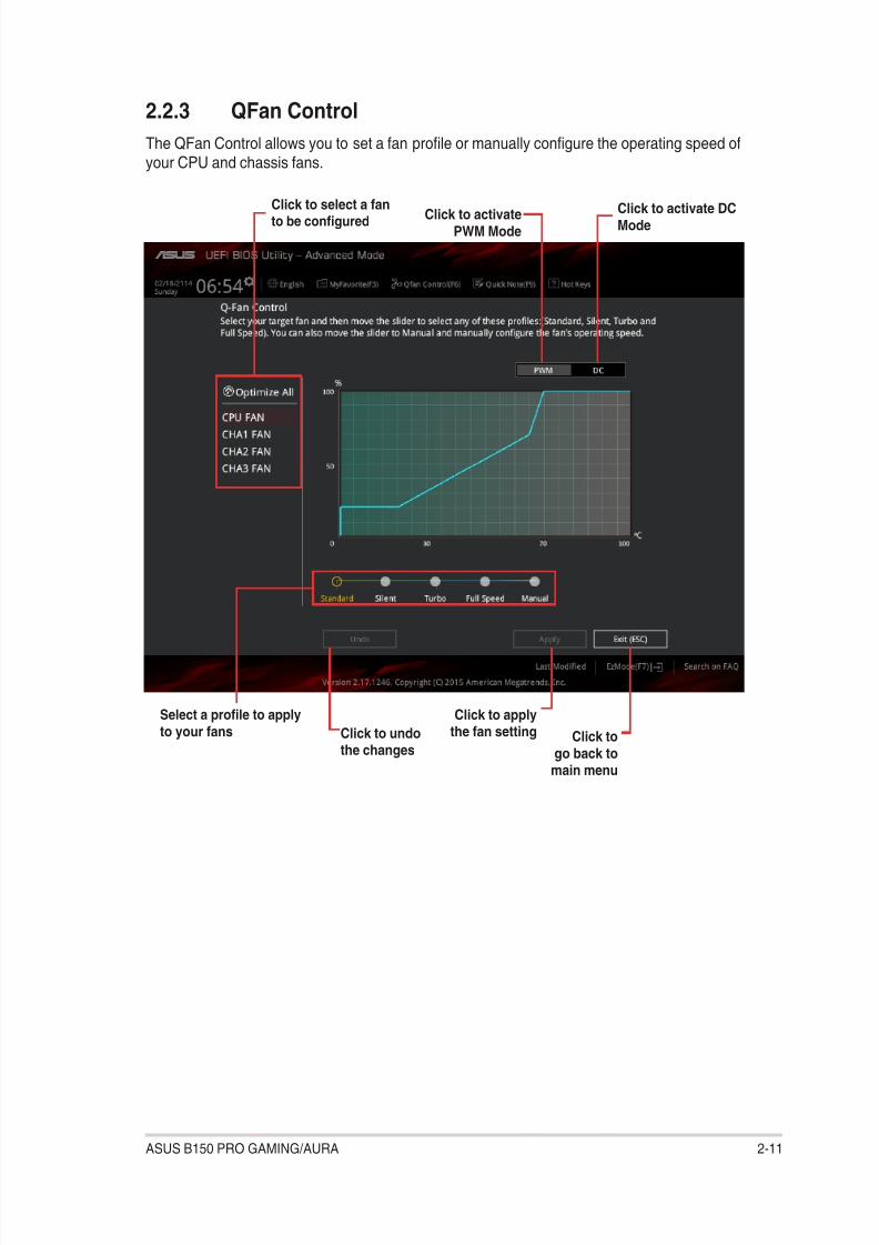
2.2.3 QFan Control
The QFan Control allows you to set a fan prole or manually congure the operating speed ofyour CPU and chassis fans.
Click to select a fanto be congured
Click to activatePWM Mode
Click to undothe changes
Click to applythe fan setting Click to
go back tomain menu
Select a prole to apply
to your fans
Click to activate DCMode
ASUS B150 PRO GAMING/AURA 2-11

8/17/2019 PLACA b150 Pro Gaming
http://slidepdf.com/reader/full/placa-b150-pro-gaming 48/92
Conguring fans manually
Select Manual from the list of proles to manually congure your fans’ operating speed.
To congure your fans:
1. Select the fan that you want to congure and to view its current status.
2. Click and drag the speed points to adjust the fans’ operating speed.
3. Click Apply to save the changes then click Exit (ESC).
Speed points Click to manuallycongure your fans
2-12 Chapter 2: Getting started

8/17/2019 PLACA b150 Pro Gaming
http://slidepdf.com/reader/full/placa-b150-pro-gaming 49/92
2.3 My FavoritesMyFavorites is your personal space where you can easily save and access your favorite
BIOS items.
My Favorites comes with several performance, power saving, and fast boot related items by
default. You can personalize this screen by adding or removing items.
Adding items to My Favorites
To add BIOS items:
1. Press <F3> on your keyboard or click from the BIOS screen to openSetup Tree Map screen.
2. On the Setup Tree Map screen, select the BIOS items that you want to save inMyFavorites screen.
Main menupanel
Submenupanel
Selectedshortcut items
ASUS B150 PRO GAMING/AURA 2‑13

8/17/2019 PLACA b150 Pro Gaming
http://slidepdf.com/reader/full/placa-b150-pro-gaming 50/92
3. Select an item from main menu panel, then click the submenu that you want to save as
favorite from the submenu panel and click .
You cannot add the following items to My Favorite items:
• User‑managed items such as language and boot order
4. Click Exit (ESC) or press <esc> key to close Setup Tree Map screen.
5. Go to My Favorites menu to view the saved BIOS items.
2.4.1 Language [English]
Allows you to choose the BIOS language version from the options. Conguration options:[English] [Español] [Русский] [Korean]
2.4.2 Security
The Security menu items allow you to change the system security settings.
• If you have forgotten your BIOS password, erase the CMOS Real Time Clock (RTC)RAM to clear the BIOS password. See section 1.6 Headers for information on how toerase the RTC RAM.
• The Administrator or User Password items on top of the screen show the defaultNot Installed. After you set a password, these items show Installed.
2.4 Main menuThe Main menu screen appears when you enter the Advanced Mode of the BIOS Setup
program. The Main menu provides you an overview of the basic system information, andallows you to set the system date, time, language, and security settings.
2-14 Chapter 2: Getting started

8/17/2019 PLACA b150 Pro Gaming
http://slidepdf.com/reader/full/placa-b150-pro-gaming 51/92
Administrator Password
If you have set an administrator password, we recommend that you enter the administratorpassword for accessing the system.
To set an administrator password:
1. Select the Administrator Password item and press <Enter>.
2. From the Create New Password box, key in a password, then press <Enter>.
3. From the Conrm New Password box, key in your password again to conrm thepassword, then click OK.
To change an administrator password:
1. Select the Administrator Password item and press <Enter>.
2. From the Enter Current Password box, key in the current password, then press<Enter>.
3. From the Create New Password box, key in a new password, then press <Enter>.
4. From the Conrm New Password box, key in your password again to conrm thepassword, then click OK.
To clear the administrator password, follow the same steps as in changing an administratorpassword, but click OK when prompted to create/conrm the password. After you clear thepassword, the Administrator Password item on top of the screen shows Not Installed.
User PasswordIf you have set a user password, you must enter the user password for accessing the system.The User Password item on top of the screen shows the default Not Installed. After you seta password, this item shows Installed.
To set a user password:
1. Select the User Password item and press <Enter>.
2. From the Create New Password box, key in a password, then press <Enter>.
3. From the Conrm New Password box, key in your password again to conrm the
password, then click OK.
To change a user password:
1. Select the User Password item and press <Enter>.
2. From the Enter Current Password box, key in the current password, then press<Enter>.
3. From the Create New Password box, key in a new password, then press <Enter>.
4. From the Conrm New Password box, key in your password again to conrm the
password, then click OK.
To clear the user password, follow the same steps as in changing a user password, but clickOK when prompted to create/conrm the password. After you clear the password, the User
Password item on top of the screen shows Not Installed.
ASUS B150 PRO GAMING/AURA 2‑15
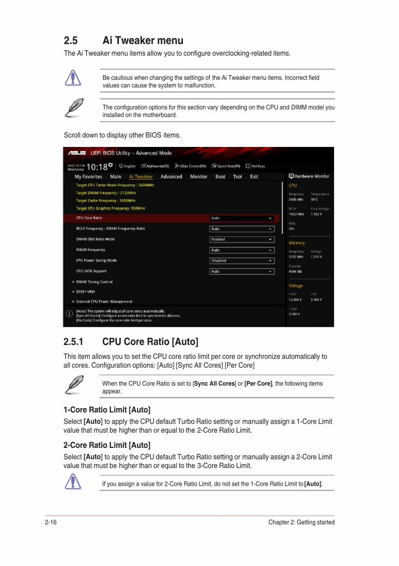
8/17/2019 PLACA b150 Pro Gaming
http://slidepdf.com/reader/full/placa-b150-pro-gaming 52/92
2.5 Ai Tweaker menuThe Ai Tweaker menu items allow you to congure overclocking‑related items.
Be cautious when changing the settings of the Ai Tweaker menu items. Incorrect eldvalues can cause the system to malfunction.
The conguration options for this section vary depending on the CPU and DIMM model youinstalled on the motherboard.
Scroll down to display other BIOS items.
2.5.1 CPU Core Ratio [Auto]
This item allows you to set the CPU core ratio limit per core or synchronize automatically to
all cores. Conguration options: [Auto] [Sync All Cores] [Per Core]
When the CPU Core Ratio is set to [Sync All Cores] or [Per Core], the following itemsappear.
1-Core Ratio Limit [Auto]
Select [Auto] to apply the CPU default Turbo Ratio setting or manually assign a 1‑Core Limitvalue that must be higher than or equal to the 2‑Core Ratio Limit.
2-Core Ratio Limit [Auto]
Select [Auto] to apply the CPU default Turbo Ratio setting or manually assign a 2‑Core Limitvalue that must be higher than or equal to the 3‑Core Ratio Limit.
If you assign a value for 2‑Core Ratio Limit, do not set the 1‑Core Ratio Limit to [Auto].
2‑16 Chapter 2: Getting started

8/17/2019 PLACA b150 Pro Gaming
http://slidepdf.com/reader/full/placa-b150-pro-gaming 53/92
3-Core Ratio Limit [Auto]
Select [Auto] to apply the CPU default Turbo Ratio setting or manually assign a 3‑Core Limitvalue that must be higher than or equal to the 4‑Core Ratio Limit.
If you assign a value for 3‑Core Ratio Limit, do not set the 1‑Core Ratio Limit and 2‑CoreRatio Limit to [Auto].
4-Core Ratio Limit [Auto]
Select [Auto] to apply the CPU default Turbo Ratio setting or manually assign a 4‑Core Limitvalue that must be lower than or equal to the 3‑Core Ratio Limit.
If you assign a value for 4‑Core Ratio Limit, do not set the 1‑Core Ratio Limit, 2‑Core Ratio
Limit, and 3‑Core Ratio to [Auto].
2.5.2 DRAM Odd Ratio Mode [Enabled]Enable Odd Ratio Mode to provide better granularity. Conguration options: [Disabled][Enabled]
2.5.3 DRAM Frequency [Auto]
This item allows you to set the memory operating frequency. The congurable options varywith the BCLK (base clock) frequency setting. Select the auto mode to apply the optimizedsetting. Conguration options: [DDR4‑800MHz] [DDR4‑933MHz] [DDR4‑1066MHz] [DDR4‑1200MHz] [DDR4‑1333MHz] [DDR4‑1400MHz] [DDR4‑1500MHz] [DDR4‑1600MHz]
[DDR4‑1700MHz] [DDR4‑1733MHz] [DDR4‑1800MHz] [DDR4‑1866MHz] [DDR4‑1900MHz][DDR4‑2000MHz] [DDR4‑2100MHz] [DDR4‑2133MHz] [DDR4‑2200MHz] [DDR4‑2266MHz][DDR4‑2300MHz] [DDR4‑2400MHz] [DDR4‑2500MHz] [DDR4‑2533MHz] [DDR4‑2600MHz][DDR4‑2666MHz] [DDR4‑2700MHz] [DDR4‑2800MHz] [DDR4‑2900MHz] [DDR4‑2933MHz][DDR4‑3000MHz] [DDR4‑3066MHz] [DDR4‑3100MHz] [DDR4‑3200MHz] [DDR4‑3333MHz][DDR4‑3466MHz] [DDR4‑3600MHz] [DDR4‑3733MHz] [DDR4‑3866MHz] [DDR4‑4000MHz][DDR4‑4133MHz] [DDR4‑4266MHz]
Selecting a very high memory frequency may cause the system to become unstable! If thishappens, revert to the default setting.
2.5.4 EPU Power Saving Mode [Disabled]
ASUS EPU (Energy Processing Unit) sets the CPU in its minimum power consumptionsettings. Enable this item to set lower CPU VCCIN and Vcore voltages and achieve the bestenergy saving condition. Conguration options: [Disabled] [Enabled]
2.5.5 CPU SVID Support [Auto]
Disabling SVID Support stops the processor from communicating with the external voltageregulator. Conguration options: [Auto] [Disabled] [Enabled]
ASUS B150 PRO GAMING/AURA 2‑17

8/17/2019 PLACA b150 Pro Gaming
http://slidepdf.com/reader/full/placa-b150-pro-gaming 54/92
2.5.6 DRAM Timing Control
The subitems in this menu allow you to set the DRAM timing control features. Use the<+> and <‑> keys to adjust the value. To restore the default setting, type [auto] using the
keyboard and press the <Enter> key.
Changing the values in this menu may cause the system to become unstable! If thishappens, revert to the default settings.
2.5.7 DIGI+ VRM
CPU Load-Line Calibration [Auto]
Load‑line is dened by Intel VRM specication and affects the CPU power voltage. The CPUworking voltage will decrease proportionally depending on the CPU loading. Higher levelsof the load‑line calibration can get a higher voltage and a better overclocking performancebut increases the CPU and VRM thermal. Select from level 1 to 7 to adjust the CPU powervoltage from 0% to 100%. Conguration options: [Auto] [Level 1] [Level 2] [Level 3] [Level 4][Level 5] [Level 6] [Level 7]
The boosted performance may vary depending on the CPU specication. Do not removethe thermal module.
CPU Current Capability [Auto]
Allows you to congure the total power range, and extends the overclocking frequency rangesimultaneously. Conguration options: [Auto] [100%] [110%] [120%] [130%] [140%]
Choose a higher value when overclocking, or under a high CPU loading for extra powersupport.
CPU VRM Switching Frequency [Auto]
This item affects the VRM transient response speed and the component thermal production.Select [Manual] to congure a higher frequency for a quicker transient response speed.Conguration options: [Auto] [Manual]
DO NOT remove the thermal module. The thermal conditions should be monitored.
The following item appears only when you set the CPU VRM Switching Frequency to[Manual].
Fixed CPU VRM Switching Frequency (KHz) [300]
This item allows you to set a higher frequency for a quicker transient response speed.Use the <+> and <‑> keys to adjust the value. The values range from 250KHz to500KHz with a 50KHz interval.
CPU Power Duty Control [T.Probe]
DIGI + VRM Duty control adjusts the current and thermal conditions of every component’sphase.
[T. Probe] Select to maintain the VRM thermal balance.
[Extreme] Select to maintain the current VRM balance.
2‑18 Chapter 2: Getting started

8/17/2019 PLACA b150 Pro Gaming
http://slidepdf.com/reader/full/placa-b150-pro-gaming 55/92
CPU Power Phase Control [Auto]
This item allows you to set the power phase control of the CPU. Conguration options: [Auto][Standard] [Optimized] [Extreme]
DO NOT remove the thermal module when setting this item to [Extreme]. The thermalconditions should be monitored.
CPU Graphics Load-Line Calibration [Auto]
Load‑line is dened by Intel VRM specication and affects the GT power voltage. The GTworking voltage will decrease proportionally depending on the GT loading. Higher levels ofthe load‑line calibration can get a higher voltage and a better overclocking performance butincreases the GT and VRM thermal. Select from level 1 to 7 to adjust the GT power voltagefrom 0% to 100%. Conguration options: [Auto] [Level 1] [Level 2] [Level 3] [Level 4] [Level 5]
[Level 6] [Level 7]
The boosted performance may vary depending on the GT specication. Do not remove thethermal module.
CPU Graphics Current Capability [Auto]
Allows you to congure the total power range, and extends the overclocking frequency rangesimultaneously. Conguration options: [Auto] [100%] [110%] [120%] [130%] [140%]
Choose a higher value when overclocking, or under a high GT loading for extra powersupport.
CPU Graphics Switching Frequency [Auto]
This item affects the GT transient response speed and the component thermal production.Select [Manual] to congure a higher frequency for a quicker transient response speed.Conguration options: [Auto] [Manual]
DO NOT remove the thermal module. The thermal conditions should be monitored.
The following item appears only when you set the CPU Graphics Switching Frequency to[Manual].
Fixed CPU Graphics Switching Frequency (KHz) [300]
This item allows you to set a higher frequency for a quicker transient response speed.Use the <+> and <‑> keys to adjust the value. The values range from 250KHz to500KHz with a 50KHz interval.
CPU Graphics Power Phase Control [Auto]
This item allows you to set the power phase control of GT. Conguration options: [Auto]
[Standard] [Optimized] [Extreme]
DO NOT remove the thermal module when setting this item to [Extreme]. The thermal
conditions should be monitored.
ASUS B150 PRO GAMING/AURA 2-19

8/17/2019 PLACA b150 Pro Gaming
http://slidepdf.com/reader/full/placa-b150-pro-gaming 56/92
2.5.8 Internal CPU Power Management
The subitems in this menu allow you to set the CPU ratio and their features.
Intel ® SpeedStepTM [Auto]
This item allows the operating system to dynamically adjust the processor voltage and coresfrequency, resulting to a decreased average power consumption and decreased averageheat production. Conguration options: [Auto] [Disabled] [Enabled]
Turbo Mode [Enabled]
This item allows you to enable your core processor’s speed to run faster than the baseoperating frequency when it is below operating power, current and temperature specication
limit. Conguration options: [Disabled] [Enabled]
The following items appear only when you set the Turbo Mode to [Enabled].
Turbo Mode Parameters
Long Duration Package Power Limit [Auto]
Allows you to limit the Turbo Ratio’s time duration that exceeds the TDP (ThermalDesign Power) for maximum performance. Use the <+> or <‑> keys to adjust the value.The values range from 1 W to 4095 W.
Package Power Time Window [Auto]
Also known as Power Limit 1, this item allows you to maintain the time window forTurbo Ratio over TDP (Thermal Design Power). Use the <+> or <‑> keys to adjust the
value. The values range from 1 to 127 in seconds.
Short Duration Package Power Limit [Auto]
Also known as Power Limit 2, this item allows you to provide rapid protection whenthe package power exceeds the Power Limit 1. Use the <+> or <‑> keys to adjust thevalue. The values range from 1 W to 4095 W.
IA AC Load Line [Auto]
This item allows you to set the AC loadline dened in 1/100 mOhms. Use the <+> and<‑> keys to adjust the value. Conguration options: [Auto] [0.01] ‑ [62.49]
IA DC Load Line [Auto]
This item allows you to set the DC loadline dened in 1/100 mOhms. Use the <+> and<‑> keys to adjust the value. Conguration options: [Auto] [0.01] ‑ [62.49]
2.5.9 CPU Core/Cache Current Limit Max. [Auto]
Allows you to set a higher current limit to prevent a frequency or power throttling whenoverclocking. Use the <+> or <‑> keys to adjust the value. The values range from 0.00A to255.50A with a 0.25A interval.
2.5.10 CPU Graphics Current Limit Max. [Auto]
Allows you to set a higher current limit to prevent a frequency or power throttling whenoverclocking. Use the <+> or <‑> keys to adjust the value. The values range from 0.00A to255.50A with a 0.25A interval.
2-20 Chapter 2: Getting started

8/17/2019 PLACA b150 Pro Gaming
http://slidepdf.com/reader/full/placa-b150-pro-gaming 57/92
2.5.11 Min. CPU Cache Ratio [Auto]
Allows you to set the minimum possible CPU cache ratio. Use the <+> or <‑> keys to adjustthe value. The values range from 8 to 34 with a 1 interval.
2.5.12 Max. CPU Cache Ratio [Auto]Allows you to set the maximum possible CPU cache ratio. Use the <+> or <‑> keys to adjustthe value. The values range from 8 to 34 with a 1 interval.
2.5.13 Max. CPU Graphics Ratio [Auto]
Allows you to set the maximum possible CPU graphics ratio. Use the <+> or <‑> keys toadjust the value. The values range from 1 to 60 with a 1 interval.
2.5.14 CPU Core/Cache Voltage [Auto]
This item allows you to congure the amount of voltage fed to the CPU cores. Increase thevoltage when setting a high Core Frequency value. Conguration options: [Auto] [ManualMode] [Offset Mode]
The following item appears only when you set the CPU Core Voltage to [Manual Mode].
CPU Core Voltage Override [Auto]
Allows you to set the input voltage for the CPU by the external voltage regulator. Use the<+> or <‑> keys to adjust the value. The values range from 0.600V to 1.700V with a 0.005Vinterval.
The following items appear only when you set the CPU Core Voltage to [Offset Mode].
Offset Mode Sign [+]
[+] To offset the voltage by a positive value.
[–] To offset the voltage by a negative value.
CPU Core Voltage Offset [Auto]
Use the <+> or <‑> keys to adjust the value. The values range from 0.005V to 0.635V with a
0.005V interval.
2.5.15 DRAM Voltage [Auto]
This item allows you to set the voltage for the DRAM. Use the <+> and <‑> keys to adjust thevalue. The values range from 1.000V to 1.800V with a 0.005 interval.
2.5.16 CPU System Agent Voltage [Auto]
This item allows you to set the voltage for the CPU System Agent. Use the <+> and <‑> keys
to adjust the value. The values range from 0.700V to 1.685V with a 0.005V interval.
2.5.17 CPU Graphics Voltage Mode [Auto]
This item allows you to congure the mode of voltage fed to the CPU Graphics Voltage.Manual mode allows user‑dened values. Offset mode modies values by SVID.Conguration options: [Auto] [Manual Mode] [Offset Mode]
ASUS B150 PRO GAMING/AURA 2-21

8/17/2019 PLACA b150 Pro Gaming
http://slidepdf.com/reader/full/placa-b150-pro-gaming 58/92
The following item appears only when you set the CPU Graphics Voltage Mode to [ManualMode].
CPU Graphics Voltage Override [Auto]
This item allows you to congure the CPU Graphics Voltage Override. Use the <+> or <‑>keys to adjust the value. The values range from 0.600V to 1.700V with a 0.005V interval.
The following item appears only when you set the CPU Core Voltage Mode to [OffsetMode].
Offset Mode Sign [+]
[+] To offset the voltage by a positive value.
[–] To offset the voltage by a negative value.
CPU Graphics Voltage Offset [Auto]
This item allows you to congure the CPU Graphics Voltage Offset. Use the <+> or <‑> keys
to adjust the value. The values range from 0.005V to 0.635V with a 0.005V interval.
2.5.18 PCH Core Voltage [Auto]This item allows you to set the PCH core voltage. Use the <+> and <‑> keys to adjust the
value. The values range from 0.800V to 1.635V with a 0.005V interval.
2.5.19 CPU Standby Voltage [Auto]This item allows you to set the voltage for the CPU Standby. Use the <+> and <‑> keys to
adjust the value. The values range from 0.800V to 1.63V with a 0.01V interval.
2.5.20 DRAM REF Voltage Control
DRAM CTRL REF Voltage [Auto]
Allows you to set the DRAM reference voltage on the control lines. You can use the <+> or<‑> keys to adjust the value. The values range from 0.39500V to 0.63000V with a 0.00500V
interval.
DRAM DATA REF Voltage on CHB [Auto]
Allows you to set the DRAM reference voltage on the data lines of channel B. You can use
the <+> or <‑> keys to adjust the value. The values range from 0.39500V to 0.63000V with a0.00500V interval.
DRAM DATA REF Voltage on CHA DIMM0 Rank0 BL0-7 [Auto]
Congures the DRAM Data REF Voltage. Conguration options: [Auto] [0] ‑ [63]
DRAM DATA REF Voltage on CHA DIMM0 Rank1 BL0-7 [Auto]
Congures the DRAM Data REF Voltage. Conguration options: [Auto] [0] ‑ [63]
DRAM DATA REF Voltage on CHA DIMM1 Rank0 BL0-7 [Auto]Congures the DRAM Data REF Voltage. Conguration options: [Auto] [0] ‑ [63]
DRAM DATA REF Voltage on CHA DIMM1 Rank1 BL0-7 [Auto]
Congures the DRAM Data REF Voltage. Conguration options: [Auto] [0] ‑ [63]
2-22 Chapter 2: Getting started
8/17/2019 PLACA b150 Pro Gaming
http://slidepdf.com/reader/full/placa-b150-pro-gaming 59/92
DRAM DATA REF Voltage on CHB DIMM0 Rank0 BL0-7 [Auto]
Congures the DRAM Data REF Voltage. Conguration options: [Auto] [0] ‑ [63]
DRAM DATA REF Voltage on CHB DIMM0 Rank1 BL0-7 [Auto]
Congures the DRAM Data REF Voltage. Conguration options: [Auto] [0] ‑ [63]
DRAM DATA REF Voltage on CHB DIMM1 Rank0 BL0-7 [Auto]
Congures the DRAM Data REF Voltage. Conguration options: [Auto] [0] ‑ [63]
DRAM DATA REF Voltage on CHB DIMM1 Rank1 BL0-7 [Auto]
Congures the DRAM Data REF Voltage. Conguration options: [Auto] [0] ‑ [63]
ASUS B150 PRO GAMING/AURA 2‑23
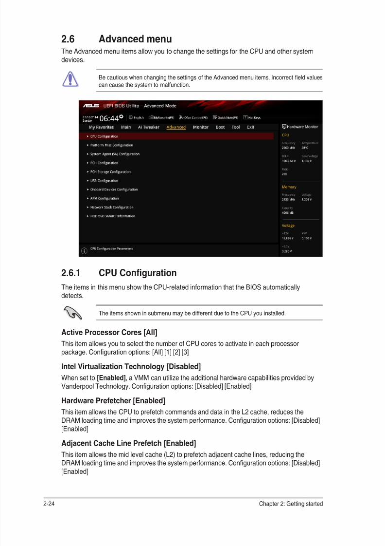
8/17/2019 PLACA b150 Pro Gaming
http://slidepdf.com/reader/full/placa-b150-pro-gaming 60/92
2.6 Advanced menuThe Advanced menu items allow you to change the settings for the CPU and other systemdevices.
Be cautious when changing the settings of the Advanced menu items. Incorrect eld values
can cause the system to malfunction.
2.6.1 CPU Conguration
The items in this menu show the CPU‑related information that the BIOS automaticallydetects.
The items shown in submenu may be different due to the CPU you installed.
Active Processor Cores [All]
This item allows you to select the number of CPU cores to activate in each processorpackage. Conguration options: [All] [1] [2] [3]
Intel Virtualization Technology [Disabled]
When set to [Enabled], a VMM can utilize the additional hardware capabilities provided byVanderpool Technology. Conguration options: [Disabled] [Enabled]
Hardware Prefetcher [Enabled]
This item allows the CPU to prefetch commands and data in the L2 cache, reduces theDRAM loading time and improves the system performance. Conguration options: [Disabled][Enabled]
Adjacent Cache Line Prefetch [Enabled]
This item allows the mid level cache (L2) to prefetch adjacent cache lines, reducing theDRAM loading time and improves the system performance. Conguration options: [Disabled]
[Enabled]
2-24 Chapter 2: Getting started

8/17/2019 PLACA b150 Pro Gaming
http://slidepdf.com/reader/full/placa-b150-pro-gaming 61/92
CPU Power Managerment Conguration
This item allows you to manage and congure the CPU’s power.
Intel ® SpeedStepTM [Auto]
This item allows the operating system to dynamically adjust the processor voltage andcores frequency, resulting to a decreased average power consumption and decreasedaverage heat production. Conguration options: [Auto] [Disabled] [Enabled]
Turbo Mode [Enabled]
This item allows you to enable your core processor’s speed to run faster than thebase operating frequency when it is below operating power, current and temperaturespecication limit. Conguration options: [Disabled] [Enabled]
CPU C states [Auto]
This item allows you to set the power saving of the CPU states. Conguration options:[Auto][Disabled] [Enabled]
The following items appear only when you set the CPU C‑States to [Enabled].
Enhanced C-States [Enabled]
This item allows your CPU to reduce power consumption when the system is in idlemode. Conguration options: [Enabled] [Disabled]
CPU C3 Report [Enabled]
This item allows you to disable or enable the CPU C3 report to the operatingsystem. Conguration options: [Enabled] [Disabled]
CPU C6 Report [Enabled] This item allows you to disable or enable the CPU C6 report to the operatingsystem. Conguration options: [Enabled] [Disabled]
CPU C7 Report [CPU C7s]
This item allows you to disable or enable the CPU C7 report to the operatingsystem. Conguration options: [Disabled] [CPU C7] [CPU C7s]
CPU C8 Report [Enabled]
This item allows you to disable or enable the CPU C8 report to the operatingsystem. Conguration options: [Enabled] [Disabled]
Package C State limit [Auto] This item allows you to set the a C‑state support for the CPU package.Conguration options: [C0/C1] [C2] [C3] [C6] [C7] [C7s] [C8] [Auto]
CFG lock [Disabled]
This item allows you to enable or disable the CFG lock. Conguration options:[Disabled] [Enabled]
2.6.2 Platform Misc Conguration
The items in this menu allow you to congure the platform‑related features.
PCI Express Native Power Management [Disabled]This item allows you to enhance the power saving feature of PCI Express and perform ASPMoperations in the operating system. Conguration options: [Disabled] [Enabled]
ASUS B150 PRO GAMING/AURA 2‑25
8/17/2019 PLACA b150 Pro Gaming
http://slidepdf.com/reader/full/placa-b150-pro-gaming 62/92
The following item appears only when you set the PCI Express Native Power Managementto [Enabled].
Native ASPM [Disabled]
[Enabled] Windows ® Vista OS controls the ASPM (active state powermanagement) support for devices.
[Disabled] BIOS controls the ASPM support for the device.
PCH - PCI Express options
DMI Link ASPM Control [Disabled]
This item allows you to control the Active State Power Management on both NB(NorthBridge) side and SB (SouthBridge) side of the DMI Link. Conguration options:[Disabled] [Enabled]
ASPM Support [Disabled]
This item allows you to select the ASPM state for energy‑saving conditions. Congurationoptions: [Disabled] [L0s] [L1] [L0sL1] [Auto]
SA - PCI Express options
DMI Link ASPM Control [Disabled]
This item allows you to control the Active State Power Management on both CPU and PCH
(platform controller hub) Both DMI link ASPM control items of the CPU and PCH sides mustbe enabled for the ASPM to take effect. Conguration options: [Disabled] [L1]
PEG ASPM [Disabled]
This item allows you to select the ASPM state for energy‑saving conditions, or use the ASUS
optimized energy saving prole. Conguration options: [Disabled] [Auto] [ASPM L0s] [ASPML1] [ASPM L0sL1]
2.6.3 System Agent (SA) Conguration
VT-d [Disabled]
Allows you to enable or disable VT‑d function on MCH. Conguration options: [Enabled]
[Disabled]
Graphics Conguration
Allows you to select a primary display from CPU, PCIE and PCI graphical devices.
Primary Display [Auto]
Allows you to select the primary display from CPU, PCIE and PCI graphics devices.
Conguration options: [Auto] [CPU Graphics] [PCIE] [PCI]
iGPU Multi-Monitor [Disabled]
This item allows you to empower both integrated and discrete graphics devices for themulti‑monitor output. The CPU graphics shared system memory size is xed at 64 MB.
Conguration options: [Disabled] [Enabled]
RC6(Render Standby) [Enabled]
Allows you to enable or disable Intel ® Graphics Render Standby support to reduceiGPU power use when the system is idle. Conguration options: [Disabled] [Enabled]
2‑26 Chapter 2: Getting started

8/17/2019 PLACA b150 Pro Gaming
http://slidepdf.com/reader/full/placa-b150-pro-gaming 63/92
DVMT Pre-Allocated [32M]
Allows you to select the amount of system memory pre‑allocated to DVMT 5.0 used bythe internal graphics device. Conguration options: [32M] [64M] [96M] [128M] [160M][192M] [224M] [256M] [288M] [320M] [352M] [384M] [416M] [448M] [480M] [512M]
[1024M]DMI/OPI Conguration
This item allows you to control various DMI (direct media interface) to run at PCI‑E 2.0 speed.
DMI Max Link Speed [Auto]
Allows you to congure the DMI speed. Conguration options: [Auto] [Gen1] [Gen2][Gen3]
PEG Port Conguration
Allows you to congure the PEG Port settings.
PCIEx16_1 Link Speed [Auto]
Allows you to congure the PCIEx16 speed for slot 1. Conguration options: [Auto]
[Gen1] [Gen2] [Gen3]
Memory Conguration
Allows you to congure the memory conguration parameters.
Memory Remap [Enabled]
Set this item to [Enabled] to support DRAM address remapping for 64‑bit operatingsystems. Conguration options: [Enabled] [Disabled]
2.6.4 PCH Conguration
This item allows you to congure the PCI Express conguration settings.
PCI Express Conguration
PCIe Speed [Auto]
Allows you to congure the PCIe speed. Conguration options: [Auto] [Gen1] [Gen2] [Gen3]
2.6.5 PCH Storage Conguration
While entering Setup, the BIOS automatically detects the presence of SATA devices. TheSATA Port items show Empty if no SATA device is installed to the corresponding SATA port.
Hyper Kit Mode [Disabled]
Disables this option for M.2 devices. Enables this option for ASUS Hyper Kit card.Conguration options: [Disabled] [Enabled]
SATA Controller(s) [Enabled]
Enables or disables onboard the SATA device. Conguration options: [Disabled] [Enabled]
The following items appear only when you set the SATA Controller(s) to [Enabled].
Aggressive LPM Support [Disabled]
This item is designed for LPM (link power management) support with a better energy savingconditions. When disabled, the hot plug function of SATA ports are disabled. Congurationoptions: [Disabled] [Enabled]
ASUS B150 PRO GAMING/AURA 2‑27
8/17/2019 PLACA b150 Pro Gaming
http://slidepdf.com/reader/full/placa-b150-pro-gaming 64/92
SMART Self Test [On]
S.M.A.R.T. (Self‑Monitoring, Analysis and Reporting Technology) is a monitoring system thatshows a warning message during POST (Power‑on Self Test) when an error occurs in thehard disks. Conguration options: [On] [Off]
SATA6G_1~6(Gray) [Enabled]
Allow you to enable/disable the SATA6G_1~6 port. Conguration options: [Disabled][Enabled]
Hot Plug [Disabled]
These items allow you to enable/disable SATA Hot Plug Support. Conguration options:[Disabled] [Enabled]
2.6.6 USB Conguration
The items in this menu allow you to change the USB‑related features.
The USB Devices item shows the auto‑detected values. If no USB device is detected, theitem shows None.
Legacy USB Support [Enabled]
[Enabled] Your system supports the USB devices in legacy operating systems.
[Disabled] Your USB devices can be used for BIOS setup only and cannot berecognized in the boot devices list.
[Auto] Your system automatically detects the presence of USB devices at startup.If any USB devices are detected, the legacy USB support is enabled.
XHCI Hand-off [Disabled]
[Enabled] Enables the support for operating systems without an XHCI hand‑off
feature.
[Disabled] Disables the XHCI Hand‑off support.
USB Single Port Control
The subitems in this menu allow you to set the USB Port Disable Override features.
USB3_1~6, USB7~12 [Enabled]
Allows you to enable or disable the USB ports individually. Conguration options:[Disabled] [Enabled]
Refer to section 1.2.3 Motherboard layout for the location of the USB ports.
2.6.7 Onboard Devices Conguration
HD Audio Controller [Enabled][Enabled] Enables the HD Audio Device.
[Disabled] Disables the HD Audio Device.
2‑28 Chapter 2: Getting started
8/17/2019 PLACA b150 Pro Gaming
http://slidepdf.com/reader/full/placa-b150-pro-gaming 65/92
The following two items appear only when you set the HD Audio Controller item to[Enabled].
Front Panel Type [HD Audio]
Allows you to set the front panel audio connector (AAFP) mode to legacy AC’97 orhigh‑denition audio depending on the audio standard that the front panel audiomodule supports.[HD] Sets the front panel audio connector (AAFP) mode to high denition
audio.
[AC97] Sets the front panel audio connector (AAFP) mode to legacy AC’97.
Depop [Enabled]
Conguration options: [Enabled] [Disabled]
SupremeFX LED Lighting [Still Mode]Allows you to set the behavior of the audio LED. Conguration options: [Disabled] [Still Mode][Breathing Mode] [Flowing Mode]
RGB LED (onboard) [Enabled]
[Enabled] The LEDs will always light up at the S0(Working), S3(Sleep), and S5(Softoff) states, but not light up at the S4/S5 state when the ErP Ready item isenabled.
[Disabled] The LEDs will not light up.
M.2 / SATA6G_1 Conguration [Auto]Conguration options: [Auto] [Manual]
The following item appears only when you set the M.2 / SATA6G_1 Conguration to [Manual].
M.2 and SATA6G_1 SATA Mode Configuration [SATA6G_1]
M.2 shares SATA mode with SATA6G_1 port. Change this item before installing M.2SATA devices.[M.2] SATA mode will be switched to M.2. SATA6G_1 can only support
PCIE devices.[SATA6G_1] SATA mode will be switched to SATA6G_1. M.2 can only support
PCIE devices.
PCIEX16_2 slot (Black) bandwidth [Auto]
[Auto] When X4 or faster card is installed on PCIe X16_2 slot, PCIe X16_2 slotruns at X4 mode for high performance support. When X1/X2 card or nocard is installed on PCIe X16_2 slot, PCIe X16_2 slot runs at X2 mode withall slots enabled.
[X4 mode] PCIe X16_2 slot runs at X4 mode for high performance support. PCIe X1_1
and PCIe X1_2 will be disabled.
[X2 mode] PCIe X16_2 slot runs at X2 mode with all slots enabled.
ASUS B150 PRO GAMING/AURA 2-29

8/17/2019 PLACA b150 Pro Gaming
http://slidepdf.com/reader/full/placa-b150-pro-gaming 66/92
Asmedia USB 3.1 Controller [Enabled]
[Enabled] Enables the onboard USB 3.0 controller.
[Disabled] Disables the controller.
Asmedia USB 3.1 Battery Charging Support [Disabled]This item appears only when the Asmedia USB 3.0 Controller item is set to [Enabled].
[Enabled] Enables the Asmedia USB 3.0 battery charging function.
[Disabled] Disables this function.
Intel LAN Controller [Enabled]
[Enabled] Enables the Intel LAN controller.
[Disabled] Disables the controller.
Intel PXE Option ROM [Off]
This item appears only when you set the previous item to [On] and allows you to enable ordisable the PXE OptionRom of the Intel LAN controller. Conguration options: [On] [Off]
USB Type C Power Switch [Auto]
[Auto] Turns off power to the Type C port when the device is not supported.
[Enabled] Turns on power to the Type C port.
Serial Port Conguration
The sub‑items in this menu allow you to set the serial port conguration.
Serial Port [On]
Allows you to enable or disable the serial port (COM).Conguration options: [On] [Off]
Change Settings [IO=3F8h; IRQ=4]
This item appears only when you set the Serial Port to [On] and allows you to selectthe Serial Port base address. Conguration options: [IO=3F8h; IRQ=4] [IO=2F8h;IRQ=3] [IO=3E8h; IRQ=4] [IO=2E8h; IRQ=3]
2.6.8 APM Conguration
ErP Ready [Disabled]
Allows BIOS to switch off some power at S4/S5 to get the system ready for ErP requirement.When set to [Enabled], all other PME options will be switched off. Conguration options:[Enable(S4+S5)] [Enable(S5)] [Disabled]
Restore AC Power Loss [Power Off]
[Power On] The system goes into on state after an AC power loss.
[Power Off] The system goes into off state after an AC power loss.
[Last State] The system goes into either off or on state, whatever the system state wasbefore the AC power loss.
2‑30 Chapter 2: Getting started

8/17/2019 PLACA b150 Pro Gaming
http://slidepdf.com/reader/full/placa-b150-pro-gaming 67/92
Power On By PS/2 Keyboard [Disabled]
[Disabled] Disables the Power On by a PS/2 keyboard.
[Space Bar] Sets the Space Bar on the PS/2 keyboard to turn on the system.
[Ctrl‑Esc] Sets the Ctrl+Esc key on the PS/2 keyboard to turn on the system.
[Power Key] Sets Power key on the PS/2 keyboard to turn on the system. This featurerequires an ATX power supply that provides at least 1A on the +5VSB lead.
Power On By PCI-E/PCI [Disabled]
This item allows you to enable or disable the Wake‑on‑LAN function of the onboard LANcontroller or other installed PCIe/PCI LAN cards. Conguration options: [Disabled] [Enabled]
Power On By Ring [Disabled]
[Disabled] Disables Ring to generate a wake event.
[Enabled] Enables Ring to generate a wake event.
Power On By RTC [Disabled]
This item allows you to enable or disable the RTC (Real‑Time Clock) to generate a wake
event and congure the RTC alarm date. When enabled, you can set the days, hours,minutes, or seconds to schedule an RTC alarm date. Conguration options: [Disabled][Enabled]
2.6.9 Network Stack Conguration
Network Stack [Disabled]
This item allows user to disable or enable the UEFI network stack. Conguration options:[Disabled] [Enabled]
The following two items appear only when you set the previous item to [Enabled].
Ipv4 / Ipv6 PXE Support [Enabled]
This item allows you to enable or disable the Ipv4/Ipv6 PXE wake event. Congurationoptions: [Disabled] [Enabled]
2.6.10 HDD/SSD SMART InformationThis menu displays the SMART information of the connected devices.
ASUS B150 PRO GAMING/AURA 2‑31

8/17/2019 PLACA b150 Pro Gaming
http://slidepdf.com/reader/full/placa-b150-pro-gaming 68/92
2.7 Monitor menuThe Monitor menu displays the system temperature/power status, and allows you to changethe fan settings.
Scroll down to display the other BIOS items.
2.7.1 CPU/ MotherBoard Temperature, VRM Temperature,PCH Temperature, T_Sensor Temperature [xxxºC/
xxxºF]/ [Ignore]
The onboard hardware monitor automatically detects and displays the CPU and motherboardtemperatures. Select [Ignore] if you do not wish to display the detected temperatures.
2.7.2 CPU Fan, Water Pump Speed, Chassis Fan 1/2/3Speed [xxxx RPM]/ [Ignore]/ [N/A]
The onboard hardware monitor automatically detects and displays the CPU fan, water pump,and chassis fan 1/2/3 speeds in rotations per minute (RPM). If the fan is not connected to themotherboard, the eld shows N/A. Select [Ignore] if you do not wish to display the detected
speed.
2.7.3 CPU Core Voltage, CPU Graphics Voltage, 3.3VVoltage, 5V Voltage, 12V Voltage, PCH Core Voltage,CPU System Agent Voltage, DRAM Voltage, CPUStandby Voltage
The onboard hardware monitor automatically detects the voltage output through the onboardvoltage regulators. Select [Ignore] if you do not want to detect this item.
2.7.4 Q-Fan CongurationThe subitems in this menu allows you to congure the Q‑Fan features.
Qfan Tuning
Click this item to automatically detect the lowest speed and congure the minimum duty cyclefor each fan.
2‑32 Chapter 2: Getting started

8/17/2019 PLACA b150 Pro Gaming
http://slidepdf.com/reader/full/placa-b150-pro-gaming 69/92
CPU Q-Fan Control [PWM Mode]
[Auto] Enables the CPU Q‑Fan control for 4‑pin CPU fan.
[Disabled] Disables the CPU Q‑Fan control feature.
[PWM Mode] Enable the CPU Q‑Fan control in PWM mode for 4‑pin CPU fan.
[DC Mode] Enable the CPU Q‑Fan control in DC mode for 3‑pin CPU fan.
CPU Fan Speed Lower Limit [300 RPM]
This item appears only when you enable the CPU Q‑Fan Control feature and allows you todisable or set the CPU fan warning speed. Conguration options: [Ignore] [200RPM] [300RPM] [400 RPM] [500 RPM] [600RPM]
CPU Fan Prole [Standard]
This item appears only when you enable the CPU Q‑Fan Control feature and allows you toset the appropriate performance level of the CPU fan.
[Standard] Sets to [Standard] to make the CPU fan automatically adjust depending onthe CPU temperature.
[Silent] Sets to [Silent] to minimize the fan speed for quiet CPU fan operation.
[Turbo] Sets to [Turbo] to achieve maximum CPU fan speed.
[Manual] Sets to [Manual] to assign detailed fan speed control parameters.
The following items appear only when you set CPU Fan Prole to [Manual].
CPU Upper Temperature [70]
Use the <+> and <‑> keys to adjust the upper limit of the CPU temperature. The valuesrange from 25ºC to 75ºC.
CPU Fan Max. Duty Cycle(%) [100]
Use the <+> and <‑> keys to adjust the maximum CPU fan duty cycle. The valuesrange from 20% to 100%. When the CPU temperature reaches the upper limit, theCPU fan will operate at the maximum duty cycle.
CPU Middle Temperature [25]
Use the <+> or <‑> keys to set the value for CPU Middle Temperature. The range of
the values depends on the CPU installed.CPU Fan Middle Duty Cycle(%) [20]
Use the <+> or <‑> keys to adjust the CPU fan middle duty cycle. The values rangefrom 20% to 100%. When the CPU temperature reaches the upper limit, the CPU fanoperates at the maximum duty cycle.
CPU Lower Temperature [20]
Use the <+> or <‑> keys to adjust the CPU fan’s lower temperature. The values rangefrom 20°C to 75°C.
CPU Fan Min. Duty Cycle(%) [20]
Use the <+> and <‑> keys to adjust the minimum CPU fan duty cycle. The valuesrange from 20% to 100%. When the CPU temperature is under the lower limit, the CPUfan will operate at the minimum duty cycle.
ASUS B150 PRO GAMING/AURA 2‑33

8/17/2019 PLACA b150 Pro Gaming
http://slidepdf.com/reader/full/placa-b150-pro-gaming 70/92
2.7.5 Chassis Fan 1/2/3 Q-Fan Control [DC Mode]
[PWM mode] Enables the chassis Q‑Fan control in PWM mode for 4‑pin chassis fan.
[DC mode] Enables the chassis Q‑Fan control in DC mode for 3‑pin chassis fan.
[Disabled] Disables the chassis Q‑Fan control feature.
The following items appear only when you set the Chassis Fan 1/2/3 Q‑Fan Control to[PWM Mode] or [DC Mode].
Chassis Fan 1/2/3 Q-Fan Source [CPU]
This item controls the assigned fan according to the selected temperature source.Conguration options: [CPU] [MotherBoard] [VRM] [PCH] [T_Sensor]
Chassis Fan 1/2/3 Speed Low Limit [300 RPM]
This item allows you to disable or set the chassis fan warning speed. Conguration options:[Ignore] [200RPM] [300 RPM] [400 RPM] [500 RPM] [600 RPM]
Chassis Fan 1/2/3 Prole [Standard]
This item allows you to set the appropriate performance level of the chassis fan.
[Standard] Sets to [Standard] to make the chassis fan automatically adjust dependingon the chassis temperature.
[Silent] Sets to [Silent] to minimize the fan speed for quiet chassis fan operation.
[Turbo] Sets to [Turbo] to achieve maximum chassis fan speed.
[Manual] Sets to [Manual] to assign detailed fan speed control parameters.
The following items appear only when you set Chassis Fan 1/2/3 Prole to [Manual].
Chassis Fan 1/2/3 Upper Temperature [70]
Use the <+> or <‑> keys to adjust the upper limit of the chassis fan temperature. Thevalues range from 45°C to 75°C.
Chassis Fan 1/2/3 Max. Duty Cycle(%) [100]
Use the <+> or <‑> keys to adjust the maximum chassis fan duty cycle. The values
range from 60% to 100%. When the chassis temperature reaches the upper limit, thechassis fan will operate at the maximum duty cycle.
Chassis Fan 1/2/3 Middle Temperature [45]
Use the <+> or <‑> keys to set the value for Chassis Fan Middle Temperature.
Chassis Fan 1/2/3 Middle Duty Cycle(%) [60]
Use the <+> or <‑> keys to adjust the chassis fan middle duty cycle. The values rangefrom 60% to 100%.
Chassis Fan 1/2/3 Lower Temperature [40]
Use the <+> or <‑> keys to adjust the chassis fans’ lower temperature. The values
range from 20°C to 75°C.Chassis Fan 1/2/3 Min. Duty Cycle(%) [60]
Use the <+> or <‑> keys to adjust the minimum chassis fan duty cycle. The values
range from 60% to 100%. When the CPU temperature is under the lower limit, thechassis fan operates at the minimum duty cycle.
2‑34 Chapter 2: Getting started
8/17/2019 PLACA b150 Pro Gaming
http://slidepdf.com/reader/full/placa-b150-pro-gaming 71/92
Water Pump Control [Disabled]
[Disabled] Disable the Water Pump control feature.
[DC mode] Enable the Water Pump control in DC mode for 3‑pin chassis fan.
[PWM mode] Enable the Water Pump control in PWM mode for 4‑pin chassis fan.
The following items appear only when you set the Water Pump Control to [DC mode] or[PWM mode].
Water Pump Upper Temperature [70]
Use the <+> or <‑> keys to adjust the upper limit of the Water Pump temperature. Thevalues range from 45 to 75.
Water Pump Max. Duty Cycle (%) [100]
Use the <+> or <‑> keys to adjust the maximum Extension Fan 1‑4 duty cycle. The
values range from 60% to 100%. When the CPU temperature reaches the upper limit,the Water Pump will operate at the maximum duty cycle.
Water Pump Middle Temperature [25]
Use the <+> or <‑> keys to adjust the middle limit of the Water Pump temperature. Thevalues range from 40 to 75.
Water Pump Middle. Duty Cycle (%) [20]
Use the <+> or <‑> keys to adjust the maximum Water Pump duty cycle. The values
range from 60% to 100%. When the CPU temperature reaches the upper limit, theWater Pump will operate at the maximum duty cycle.
Water Pump Lower Temperature [20]Use the <+> or <‑> keys to adjust the lower limit of the Water Pump temperature. The
values range from 0 to 75. The Water Pump will operate at the minimum duty cyclewhen the temperature is lower than the limit.
Water Pump Min. Duty Cycle(%) [20]
Use the <+> or <‑> keys to adjust the minimum Water Pump duty cycle. The values
range from 60% to 100%. When the CPU temperature is under the limit, the WaterPump will operate at the minimum duty cycle.
2.7.6 Anti Surge Support [On]
This item allows you to enable or disable the Anti Surge function. Conguration options: [On] [Off]
ASUS B150 PRO GAMING/AURA 2‑35
8/17/2019 PLACA b150 Pro Gaming
http://slidepdf.com/reader/full/placa-b150-pro-gaming 72/92
2.8 Boot menuThe Boot menu items allow you to change the system boot options.
Scroll down to display the other BIOS items.
2.8.1 Fast Boot [Enabled]
[Enabled] Select to accelerate the boot speed.
[Disabled] Select to go back to normal boot speed.
Next Boot after AC Power Loss [Normal Boot]
[Normal Boot] Returns to normal boot on the next boot after AC power loss.
[Fast Boot] Accelerates the boot speed on the next boot after AC power loss.
2.8.2 Boot Logo Display [Auto]
[Auto] Adjusts logo automatically based on Windows ® display requrements.
[Full Screen] Maximize the boot logo size.
[Disabled] Hide the logo during POST.
POST Delay Time [3 sec]
This item appears only when you set Boot Logo Display to [Auto] and [Full Screen]. This itemallows you to select the desired additional POST waiting time to easily enter the BIOS setup.
You can only execute the POST delay time during Normal Boot. The values range from 0 to10 seconds.
This feature will only work under normal boot.
Post Report [5 sec]
This item appears only when you set Boot Logo Display to [Disabled]. This item allows you to
select a desired post report waiting time. Conguration options: [1 sec] ~ [10 sec] [Until PressESC].
2.8.3 Boot up NumLock State [Enabled]
This item allows you to enable or disable power‑on state of the NumLock. Congurationoptions: [Disabled] [Enabled]
2‑36 Chapter 2: Getting started

8/17/2019 PLACA b150 Pro Gaming
http://slidepdf.com/reader/full/placa-b150-pro-gaming 73/92
2.8.4 Wait for ‘F1’ If Error [Enabled]
When this item is set to [Enabled], the system waits for the F1 key to be pressed when erroroccurs. Conguration options: [Disabled] [Enabled]
2.8.5 Option ROM Messages [Force BIOS][Force BIOS] The third‑party ROM messages will be displayed during POST.
[Keep Current] Disables the ROM messages and displays only the ASUS logo duringPOST.
2.8.6 Interrupt 19 Capture [Disabled]
This item allows you to trap Interrupt 19 by the option ROMs. Conguration options:
[Disabled] [Enabled]
2.8.7 Setup Mode [EZ Mode][Advanced Mode] This item allows you to go to Advanced Mode of the BIOS after POST.
[EZ Mode] This item allows you to go to EZ Mode of the BIOS after POST.
2.8.8 CSM (Compatibility Support Module)
Allows you to congure the CSM (Compatibility Support Module) items to fully support thevarious VGA, bootable devices and add‑on devices for better compatibility.
Launch CSM [Enabled]
[Auto] The system automatically detects the bootable devices and the add‑ondevices.
[Enabled] For better compatibility, enable the CSM to fully support the non‑UEFIdriver add‑on devices or the Windows ® UEFI mode.
[Disabled] Disable the CSM to fully support the Windows ® Security Update andSecurity Boot.
The following four items appear when you set Launch CSM to [Enabled].
Boot Device Control [UEFI and Legacy OPROM]
Allows you to select the type of devices that you want to boot up. Conguration options:[UEFI and Legacy OPROM] [Legacy OPROM only] [UEFI only]
Boot from Network Devices [Legacy only]
Allows you to select the type of network devices that you want to launch. Congurationoptions: [Ignore] [Legacy only] [UEFI driver rst]
Boot from Storage Devices [Legacy Only]
Allows you to select the type of storage devices that you want to launch. Congurationoptions: [Ignore] [Legacy only] [UEFI driver rst]
Boot from PCI-E/PCI Expansion Devices [Legacy Only]
Allows you to select the type of PCIe/PCI expansion devices that you want to launch.Conguration options: [Legacy only] [UEFI driver rst]
ASUS B150 PRO GAMING/AURA 2‑37
8/17/2019 PLACA b150 Pro Gaming
http://slidepdf.com/reader/full/placa-b150-pro-gaming 74/92
2.8.9 Secure Boot
Allows you to congure the Windows ® Secure Boot settings and manage its keys to protectthe system from unauthorized access and malwares during POST.
OS Type [Windows UEFI mode]Allows you to select your installed operating system.
[Windows UEFI mode] This item allows you to select your installed operating system.Execute the Microsoft ® Secure Boot check. Only select thisoption when booting on Windows ® UEFI mode or other Microsoft ® Secure Boot compliant OS.
[Other OS] Get the optimized function when booting on Windows ® non‑UEFImode. Microsoft ® Secure Boot only supports Windows ® UEFImode.
Key ManagementThis allows you to manage the Secure Boot keys.
Clear Secure Boot keys
This item appears only when you load the default Secure Boot keys. This item allowsyou to clear all the previously applied Secure Boot keys.
Save Secure Boot Keys
This item allows you to save all the Secure Boot keys to a USB storage device.
PK Management
The Platform Key (PK) locks and secures the rmware from any non‑permissiblechanges. The system veries the PK before your system enters the OS.
Set New Key
This item allows you to load the downloaded PK from a USB storage device.
Delete key
Allows you to delete the PK from your system. Once the PK is deleted, all thesystem’s Secure Boot keys will not be active. Conguration options: [Yes] [No]
The PK le must be formatted as a public key certicate or UEFI variable structure withtime‑based authenticated variable.
KEK Management
The KEK (Key‑exchange Key or Key Enrollment Key) manages the Signature database(db) and Revoked Signature database (dbx).
Key‑exchange Key (KEK) refers to Microsoft ® Secure Boot Key‑Enrollment Key (KEK).
Set New Key
Allows you to load the downloaded KEK from a USB storage device.
Append Key
Allows you to load the additional KEK from a storage device for an additional db anddbx loaded management.
The KEK le must be formatted as a public key certicate or UEFI variable structure withtime‑based authenticated variable.
2‑38 Chapter 2: Getting started
8/17/2019 PLACA b150 Pro Gaming
http://slidepdf.com/reader/full/placa-b150-pro-gaming 75/92
Delete key
Allows you to delete the Key from your system. Conguration options: [Yes] [No]
DB Management
The db (Authorized Signature database) lists the signers or images of UEFI
applications, operating system loaders, and UEFI drivers that you can load on thesingle computer.
Set New Key
Allows you to load the downloaded db from a USB storage device.
Append Key
Allows you to load the additional KEK from a storage device for an additional db anddbx loaded management.
The KEK le must be formatted as a public key certicate or UEFI variable structure withtime‑based authenticated variable.
Delete key
Allows you to delete the Key from your system. Conguration options: [Yes] [No]
DBX Management
The DBX (Revoked Signature database) lists the forbidden images of db items that areno longer trusted and cannot be loaded.
Set New Key
Allows you to load the downloaded dbx from a USB storage device.
Append Key Allows you to load the additional KEK from a storage device for an additional db anddbx loaded management.
The KEK le must be formatted as a public key certicate or UEFI variable structure withtime‑based authenticated variable.
Delete key
Allows you to delete the Key from your system. Conguration options: [Yes] [No]
2.8.11 Boot Option Priorities
These items specify the boot device priority sequence from the available devices. Thenumber of device items that appears on the screen depends on the number of devicesinstalled in the system.
• To access Windows ® OS in Safe Mode, press <F8 > after POST (Windows ® 8 notsupported).
• To select the boot device during system startup, press <F8> when ASUS Logoappears.
2.8.12 Boot OverrideThese items displays the available devices. The number of device items that appears onthe screen depends on the number of devices installed in the system. Click an item to start
booting from the selected device.
ASUS B150 PRO GAMING/AURA 2‑39
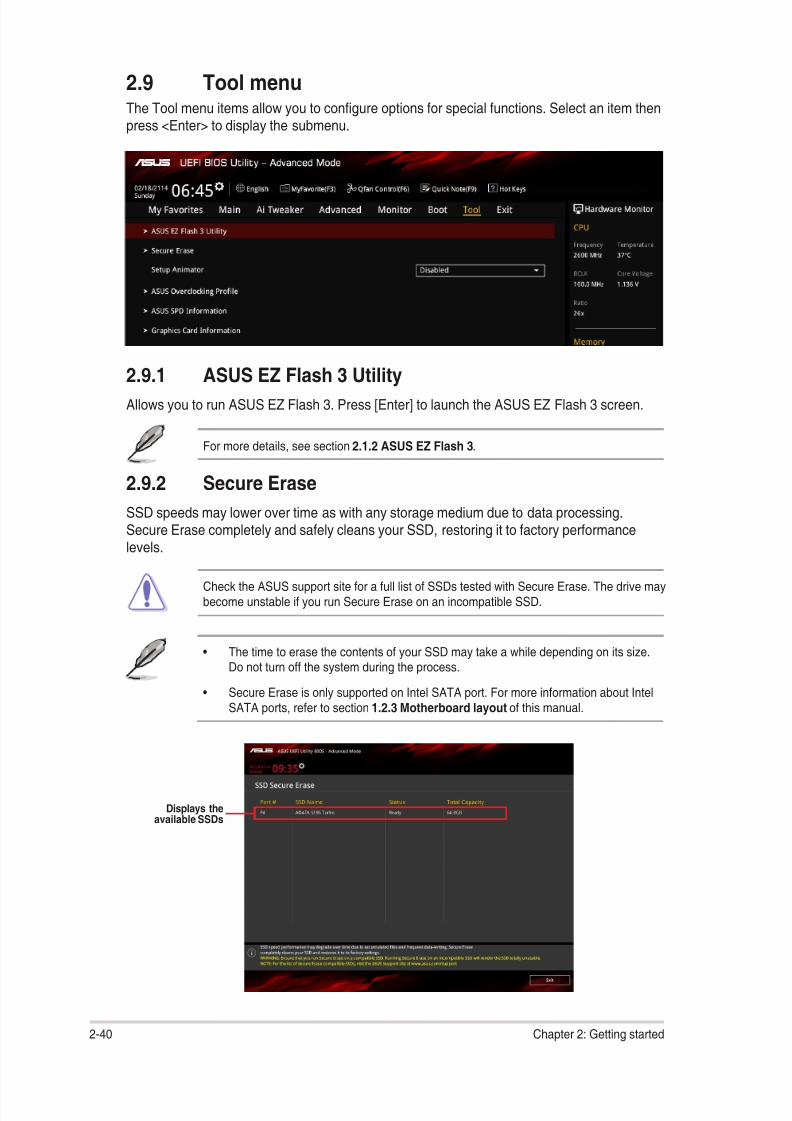
8/17/2019 PLACA b150 Pro Gaming
http://slidepdf.com/reader/full/placa-b150-pro-gaming 76/92
2.9 Tool menuThe Tool menu items allow you to congure options for special functions. Select an item thenpress <Enter> to display the submenu.
2.9.1 ASUS EZ Flash 3 Utility
Allows you to run ASUS EZ Flash 3. Press [Enter] to launch the ASUS EZ Flash 3 screen.
For more details, see section 2.1.2 ASUS EZ Flash 3.
2.9.2 Secure Erase
SSD speeds may lower over time as with any storage medium due to data processing.
Secure Erase completely and safely cleans your SSD, restoring it to factory performancelevels.
Check the ASUS support site for a full list of SSDs tested with Secure Erase. The drive maybecome unstable if you run Secure Erase on an incompatible SSD.
• The time to erase the contents of your SSD may take a while depending on its size.Do not turn off the system during the process.
• Secure Erase is only supported on Intel SATA port. For more information about IntelSATA ports, refer to section 1.2.3 Motherboard layout of this manual.
Displays theavailable SSDs
2-40 Chapter 2: Getting started

8/17/2019 PLACA b150 Pro Gaming
http://slidepdf.com/reader/full/placa-b150-pro-gaming 77/92
Status denition:
• Frozen. The frozen state is the result of a BIOS protective measure. The BIOSguards drives that do not have password protection by freezing them prior to booting.If the drive is frozen, a power off or hard reset of your PC must be performed to
proceed with the Secure Erase.
• Locked. SSDs might be locked if the Secure Erase process is either incompleteor was stopped. This may be due to a third party software that uses a differentpassword dened by ASUS. You have to unlock the SSD in the software beforeproceeding with Secure Erase.
2.9.3 Setup Animator [Disabled]
Enables or disables the Setup animator. Conguration options: [Disabled] [Enabled]
2.9.4 ASUS Overclocking ProleThis item allows you to store or load multiple BIOS settings.
The Overclocking Prole items show Not assigned if no prole is created.
Load from Prole
Allows you to load the previous BIOS settings saved in the BIOS Flash. Key in the prole
number that saved your CMOS settings, press <Enter>, and then select Yes.
• DO NOT shut down or reset the system while updating the BIOS to prevent thesystem boot failure!
• We recommend that you update the BIOS le only coming from the same memory/ CPU conguration and BIOS version.
Prole Name
Allows you to create a name for the prole you want to save.
Save to Prole
Allows you to save the current BIOS settings to the BIOS Flash, and create a prole. Key in aprole number from one to eight, press <Enter>, and then select Yes.
Load/Save Prole from/to USB Drive
This item allows you to load or save prole from your USB drive, load and save prole to yourUSB drive.
2.9.5 ASUS SPD Information
DIMM Slot Number [DIMM_A2]
Displays the Serial Presence Detect (SPD) information of the DIMM module installed on theselected slot. Conguration options: [DIMM_A1] [DIMM_B1] [DIMM_A2] [DIMM_B2]
2.9.6 Graphics Card Information
This item displays the information about the graphics card installed in your system.
ASUS B150 PRO GAMING/AURA 2-41
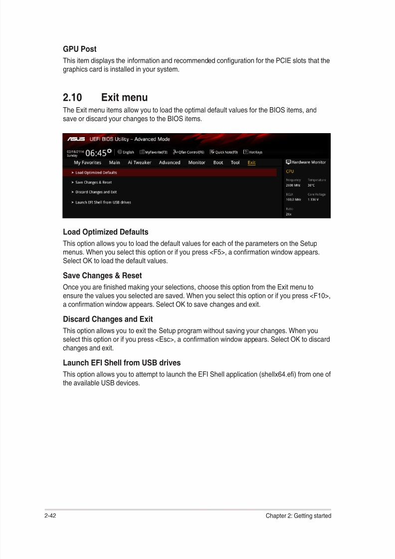
8/17/2019 PLACA b150 Pro Gaming
http://slidepdf.com/reader/full/placa-b150-pro-gaming 78/92
GPU Post
This item displays the information and recommended conguration for the PCIE slots that thegraphics card is installed in your system.
Load Optimized Defaults
This option allows you to load the default values for each of the parameters on the Setupmenus. When you select this option or if you press <F5>, a conrmation window appears.Select OK to load the default values.
Save Changes & Reset
Once you are nished making your selections, choose this option from the Exit menu toensure the values you selected are saved. When you select this option or if you press <F10>,a conrmation window appears. Select OK to save changes and exit.
Discard Changes and Exit
This option allows you to exit the Setup program without saving your changes. When youselect this option or if you press <Esc>, a conrmation window appears. Select OK to discardchanges and exit.
Launch EFI Shell from USB drives
This option allows you to attempt to launch the EFI Shell application (shellx64.e) from one ofthe available USB devices.
2.10 Exit menuThe Exit menu items allow you to load the optimal default values for the BIOS items, andsave or discard your changes to the BIOS items.
2-42 Chapter 2: Getting started

8/17/2019 PLACA b150 Pro Gaming
http://slidepdf.com/reader/full/placa-b150-pro-gaming 79/92
1. Insert the Windows ® 7 installation DVD into a USB ODD, or copy all les on theWindows ® 7 installation DVD to a USB storage device on a working system.
2. Connect the USB ODD or USB storage device to your 100 series platform.
3. Insert the ASUS support DVD into a SATA ODD on your 100 series platform.
4. Power on your system and press F8 during POST (Power‑On Self Test) to enter theboot screen.
2.11.1 Windows ® 7 and USB 3.0 driver for 100 SeriesBased on the chipset specication, the 100 series requires USB 3.0 drivers to be preloadedin order to use USB keyboard/mouse during Windows ® 7 installation. This section is a guideon preloading USB 3.0 drivers and installing Windows ® 7.
Method 1: Using SATA ODD & USB devices
Load USB 3.0 drivers using the ASUS support DVD and install Windows ®
7 using a USBdevice.
Requirement:
• 1 x ASUS support DVD
• 1 x Windows ® 7 installation source
• 1 x SATA ODD
• 1 x USB device (ODD or storage)
The USB storage device requires 8 GB or more capacity. It is recommended to format thestorage device before use.
2.11 Installing an operating system
Motherboard settings and hardware options vary. The setup procedures presented in thischapter are for reference only. Refer to Windows ® operating system documentation for
detailed information.
ASUS B150 PRO GAMING/AURA 2‑43
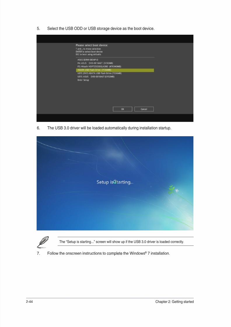
8/17/2019 PLACA b150 Pro Gaming
http://slidepdf.com/reader/full/placa-b150-pro-gaming 80/92
6. The USB 3.0 driver will be loaded automatically during installation startup.
The “Setup is starting...” screen will show up if the USB 3.0 driver is loaded correctly.
7. Follow the onscreen instructions to complete the Windows ® 7 installation.
5. Select the USB ODD or USB storage device as the boot device.
2-44 Chapter 2: Getting started

8/17/2019 PLACA b150 Pro Gaming
http://slidepdf.com/reader/full/placa-b150-pro-gaming 81/92
Method 2: Using a modied Windows ® 7 ISO
Load USB 3.0 drivers and install Windows ® 7 using a modied Windows ® 7 installation DVD.
Requirement:
• 1 x ASUS support DVD
• 1 x Windows ® 7 installation source
• 1 x Working system (PC or notebook)
• 1 x SATA ODD
1. On your working system, create an ISO image le of the Windows ® 7 installationsource using a third‑party ISO software.
2. Copy both “Auto_Unattend.xml” and “Auto_Unattend” folder from the root directory ofthe ASUS supporting DVD to your system.
3. Edit the ISO le and add both “Auto_Unattend.xml” and “Auto_Unattend” folder into theISO le.
4. Burn this ISO le onto an empty DVD to create a modied Windows ® 7 installationDVD.
5. Insert the modied Windows ® 7 installation DVD into an ODD on your 100 seriesplatform.
6. Power on your system and press F8 during POST (Power‑On Self Test) to enter theboot screen.
7. Select the ODD as the boot device.
8. The USB 3.0 driver will be loaded automatically during installation startup.
The “Setup is starting...” screen will show up if the USB 3.0 driver is loaded correctly.
9. Follow the onscreen instructions to complete the Windows ® 7 installation.
ASUS B150 PRO GAMING/AURA 2‑45

8/17/2019 PLACA b150 Pro Gaming
http://slidepdf.com/reader/full/placa-b150-pro-gaming 82/92
Method 3: Using ASUS EZ Installer
Use the ASUS EZ Installer to create a modied Windows ® 7 installation source.
Requirement:
• 1 x ASUS support DVD
• 1 x Windows ® 7 installation DVD
• 1 x Working system (PC or notebook)
• 1 x SATA ODD
• 1 x USB storage device (8 GB or more)
1. Insert the Windows ® 7 installation DVD.
2. Launch the ASUS EZ Installer located on the ASUS support DVD.
3. Select a method of creating a modied Windows ® 7 installation le:
• Windows ® 7 OS disk to USB storage device
- Select Windows 7 OS disk to USB storage device then click Next.
‑ Check I agree and then click Next.
2‑46 Chapter 2: Getting started

8/17/2019 PLACA b150 Pro Gaming
http://slidepdf.com/reader/full/placa-b150-pro-gaming 83/92
‑ Select the source of the Windows ® 7 installation disk then click Next.
‑ Select the USB storage device and click next.
Click the refresh icon if the USB storage device is not displayed.
‑ Click Yes to clear the contents on the USB storage device and create abootable USB device.
Make sure to backup contents on the USB storage device, as it will be formatted.
‑ Once completed, click OK to nish.
ASUS B150 PRO GAMING/AURA 2‑47

8/17/2019 PLACA b150 Pro Gaming
http://slidepdf.com/reader/full/placa-b150-pro-gaming 84/92
• Windows ® 7 OS disk to ISO le
- Select Windows 7 OS disk to ISO le then click Next.
‑ Check I agree and then click Next.
‑ Select the source of the Windows ® 7 installation disk then click Next.
2‑48 Chapter 2: Getting started

8/17/2019 PLACA b150 Pro Gaming
http://slidepdf.com/reader/full/placa-b150-pro-gaming 85/92
‑ Select the folder to save the modied Windows ® 7 installation ISO le and clickNext.
‑ Once completed, click OK to nish.
‑ Burn this ISO le onto an empty DVD to create a modied Windows ® 7
installation DVD.
4. Insert the modied Windows ® 7 installation DVD into an ODD or connect the USBstorage device with modied Windows ® 7 installation les onto your 100 seriesplatform.
5. Power on your system and press F8 during POST (Power‑On Self Test) to enter the
boot screen.6. Select the ODD or USB storage device as the boot device.
7. The USB 3.0 driver will be loaded automatically during installation startup.
The “Setup is starting...” screen will show up if the USB 3.0 driver is loaded correctly.
8. Follow the onscreen instructions to complete the Windows ® 7 installation.
ASUS B150 PRO GAMING/AURA 2-49

8/17/2019 PLACA b150 Pro Gaming
http://slidepdf.com/reader/full/placa-b150-pro-gaming 86/92
2‑50 Chapter 2: Getting started

8/17/2019 PLACA b150 Pro Gaming
http://slidepdf.com/reader/full/placa-b150-pro-gaming 87/92
Appendices
Notices
Federal Communications Commission StatementThis device complies with Part 15 of the FCC Rules. Operation is subject to the following twoconditions:
• This device may not cause harmful interference.
• This device must accept any interference received including interference that may causeundesired operation.
This equipment has been tested and found to comply with the limits for a Class B digitaldevice, pursuant to Part 15 of the FCC Rules. These limits are designed to provide
reasonable protection against harmful interference in a residential installation. Thisequipment generates, uses and can radiate radio frequency energy and, if not installedand used in accordance with manufacturer’s instructions, may cause harmful interferenceto radio communications. However, there is no guarantee that interference will not occurin a particular installation. If this equipment does cause harmful interference to radio ortelevision reception, which can be determined by turning the equipment off and on, the useris encouraged to try to correct the interference by one or more of the following measures:
• Reorient or relocate the receiving antenna.
• Increase the separation between the equipment and receiver.
• Connect the equipment to an outlet on a circuit different from that to which the receiveris connected.
• Consult the dealer or an experienced radio/TV technician for help.
The use of shielded cables for connection of the monitor to the graphics card is requiredto assure compliance with FCC regulations. Changes or modications to this unit notexpressly approved by the party responsible for compliance could void the user’s authorityto operate this equipment.
IC: Canadian Compliance Statement
Complies with the Canadian ICES-003 Class B specications. This device complies with RSS210 of Industry Canada. This Class B device meets all the requirements of the Canadianinterference-causing equipment regulations.This device complies with Industry Canada license exempt RSS standard(s). Operation issubject to the following two conditions: (1) this device may not cause interference, and (2)this device must accept any interference, including interference that may cause undesiredoperation of the device.Cut appareil numérique de la Classe B est conforme à la norme NMB-003 du Canada.Cet appareil numérique de la Classe B respecte toutes les exigences du Règlement sur le
matériel brouilleur du Canada.
Cet appareil est conforme aux normes CNR exemptes de licence d’Industrie Canada. Lefonctionnement est soumis aux deux conditions suivantes :(1) cet appareil ne doit pas provoquer d’interférences et(2) cet appareil doit accepter toute interférence, y compris celles susceptibles de provoquerun fonctionnement non souhaité de l’appareil.
ASUS B150 PRO GAMING/AURA A-1
8/17/2019 PLACA b150 Pro Gaming
http://slidepdf.com/reader/full/placa-b150-pro-gaming 88/92
REACH
Complying with the REACH (Registration, Evaluation, Authorisation, and Restriction ofChemicals) regulatory framework, we published the chemical substances in our products atASUS REACH website at http://csr.asus.com/english/REACH.htm.
DO NOT throw the motherboard in municipal waste. This product has been designed toenable proper reuse of parts and recycling. This symbol of the crossed out wheeled binindicates that the product (electrical and electronic equipment) should not be placed inmunicipal waste. Check local regulations for disposal of electronic products.
DO NOT throw the mercury-containing button cell battery in municipal waste. This symbolof the crossed out wheeled bin indicates that the battery should not be placed in municipalwaste.
ASUS Recycling/Takeback ServicesASUS recycling and takeback programs come from our commitment to the highest standardsfor protecting our environment. We believe in providing solutions for you to be able toresponsibly recycle our products, batteries, other components as well as the packagingmaterials. Please go to http://csr.asus.com/english/Takeback.htm for detailed recyclinginformation in different regions.
Canadian Department of Communications Statement
This digital apparatus does not exceed the Class B limits for radio noise emissions fromdigital apparatus set out in the Radio Interference Regulations of the Canadian Department
of Communications.
This class B digital apparatus complies with Canadian ICES-003.
VCCI: Japan Compliance Statement
VCCI Class B Statement
This is a Class B product based on the standard of the VCCI Council. If this is used near aradio or television receiver in a domestic environment, it may cause radio interference. Installand use the equipment according to the instruction manual.
KC: Korea Warning Statement
A-2 Appendices

8/17/2019 PLACA b150 Pro Gaming
http://slidepdf.com/reader/full/placa-b150-pro-gaming 89/92
Română Prin prezenta, AsusTek Inc. declară faptul că acest dispozitivrespectă cerinţele esenţiale şi alte prevederi relevante ale directivelor CE.Pentru mai multe detalii, consultaţi declaraţia de conformitate CE.
Srpski AsusTek Inc. ovim izjavljuje da je ovaj uređaj u saglasnosti saključnim zahtevima i drugim relevantnim odredbama CE Direktiva. Molimovas, pogledajte CE Deklaraciju o usklađenosti za više detalja.
Slovensky Spoločnosť AsusTek Inc. týmto prehlasuje, že toto zariadenievyhovuje príslušným požiadavkám a ďalším súvisiacim ustanoveniamsmerníc ES. Viac podrobností si pozrite v prehlásení o zhode ES.
Slovenščina AsusTek Inc. tukaj izjavlja, da je ta naprava skladna stemeljnimi zahtevami in drugimi relevantnimi določili direktiv CE. Za večinformacij glejte Izjavo CE o skladnosti.
Español Por la presente, AsusTek Inc. declara que este dispositivo cumplelos requisitos básicos y otras disposiciones relevantes de las directivasde la CE. Consulte la Declaración de conformidad de la CE para obtener
más detalles.
Svenska AsusTek Inc. förklarar härmed att denna enhet är i
överensstämmelse med de grundläggande kraven och andra relevantabestämmelser i CE-direktiven. Se CE-försäkran om överensstämmelse för
mer information.
Українська AsusTek Inc. заявляє, що цей пристрій відповідає основним
вимогам відповідних Директив ЄС. Будь ласка, див. більше подробиць у
Декларації відповідності нормам ЄС.
Türkçe AsusTek Inc., bu aygıtın temel gereksinimlerle ve CE Yönergelerinindiğer ilgili koşullarıyla uyumlu olduğunu beyan eder. Daha fazla ayrıntı içinlütfen CE Uygunluk Beyanına bakın.
Bosanski AsusTek Inc. ovim potvrđuje da je ovaj uređaj usklađen sosnovnim zahtjevima i drugim relevantnim propisima Direktiva EK. Za višeinformacija molimo pogledajte Deklaraciju o usklađenosti EK.
English AsusTek Inc. hereby declares that this device is in compliance withthe essential requirements and other relevant provisions of CE Directives.Please see the CE Declaration of Conformity for more details.
Français AsusTek Inc. déclare par la présente que cet appareil est
conforme aux critères essentiels et autres clauses pertinentes des directiveseuropéennes. Veuillez consulter la déclaration de conformité CE pour plusd’informations.
Deutsch AsusTek Inc. erklärt hiermit, dass dieses Gerät mit denwesentlichen Anforderungen und anderen relevanten Bestimmungen derCE-Richtlinien übereinstimmt. Weitere Einzelheiten entnehmen Sie bitte derCE-Konformitätserklärung.
Italiano AsusTek Inc. con la presente dichiara che questo dispositivo
è conforme ai requisiti essenziali e alle altre disposizioni pertinenti alledirettive CE. Per maggiori informazioni fate riferimento alla dichiarazione diconformità CE.
Компания ASUS заявляет, что это устройство соответствует основным
требованиям и другим соответствующим условиям европейских директив.
Подробную информацию, пожалуйста, смотрите в декларации соответствия.
Български С настоящото AsusTek Inc. декларира, че това устройство
е в съответствие със съществените изисквания и другите приложимипостановления на директивите CE. Вижте CE декларацията за съвместимост
за повече информация.
Hrvatski AsusTek Inc. ovim izjavljuje da je ovaj uređaj sukladan sbitnim zahtjevima i ostalim odgovarajućim odredbama CE direktiva. Višepojedinosti potražite u CE izjavi o sukladnosti.
Čeština Společnost AsusTek Inc. tímto prohlašuje, že toto zařízenísplňuje základní požadavky a další příslušná ustanovení směrnic CE. Dalšípodrobnosti viz Prohlášení o shodě CE.
Dansk AsusTek Inc. Erklærer hermed, at denne enhed er ioverensstemmelse med hovedkravene and andre relevante bestemmelser iCE-direktiverne. Du kan læse mere i CE-overensstemmelseserklæring.
Nederlands AsusTek Inc. verklaart hierbij dat dit apparaat compatibel
is met de essentiële vereisten en andere relevante bepalingen van CE-richtlijnen. Raadpleeg de CE-verklaring van conformiteit voor meer details.
Eesti Käesolevaga kinnitab AsusTek Inc., et see seade vastab CEdirektiivide oluliste nõuetele ja teistele asjakohastele sätetele. Vt üksikasju
CE vastavusdeklaratsioonist.
Suomi AsusTek Inc. vakuuttaa täten, että tämä laite on CE-direktiivienolennaisten vaatimusten ja muiden asiaan kuuluvien lisäysten mukainen.Katso lisätietoja CE-vaatimustenmukaisuusvakuutuksesta.
Ελληνικά Με το παρόν, η AsusTek Inc. Δηλώνει ότι αυτή η συσκευή
συμμορφώνεται με τις θεμελιώδεις απαιτήσεις και άλλες σχετικές διατάξεις
των Οδηγιών της ΕΕ. Για περισσότερες λεπτομέρειες ανατρέξτε στην Δήλωση
Συμμόρφωσης ΕΕ.
Magyar Az AsusTek Inc. ezennel kijelenti, hogy a készülék megfelel
a CE-irányelvek alapvető követelményeinek és ide vonatkozó egyébrendelkezéseinek. További részletekért tekintse meg a CE-megfelelőséginyilatkozatot.
Latviski Līdz ar šo AsusTek Inc. paziņo, ka šī ierīce atbilst būtiskajāmprasībām un citiem saistošajiem nosacījumiem, kas norādīti CE direktīvā. Laiuzzinātu vairāk, skatiet CE Atbilstības deklarāciju.
Lietuvių Šiuo dokumentu bendrovė „AsusTek Inc.“ pareiškia, kad šisįrenginys atitinka pagrindinius CE direktyvų reikalavimus ir kitas susijusiasnuostatas. Daugiau informacijos rasite CE atitikties deklaracijoje.
Norsk AsusTek Inc. erklærer herved at denne enheten er i samsvar medhovedsaklige krav og andre relevante forskrifter i CE-direktiver. Du nnermer informasjon i CE-samsvarserklæringen.
Polski Niniejszym AsusTek Inc. deklaruje, że to urządzenie jest zgodne zistotnymi wymaganiami oraz innymi powiązanymi zaleceniami Dyrektyw CE.
W celu uzyskania szczegółów, sprawdź Deklarację zgodności CE.
Português A AsusTek Inc. declara que este dispositivo está emconformidade com os requisitos essenciais e outras disposições relevantesdas Diretivas da CE. Para mais detalhes, consulte a Declaração deConformidade CE.
ASUS B150 PRO GAMING/AURA A-3

8/17/2019 PLACA b150 Pro Gaming
http://slidepdf.com/reader/full/placa-b150-pro-gaming 90/92
ASUS contact information
ASUSTeK COMPUTER INC.Address 15 Li-Te Road, Peitou, Taipei, Taiwan 11259Telephone +886-2-2894-3447
Fax +886-2-2890-7798E-mail [email protected] site http://www.asus.com
Technical Support Telephone +86-21-3842-9911Fax +86-21-5866-8722 ext. 9101#Online support http://support.asus.com/techserv/techserv.aspx
ASUS COMPUTER INTERNATIONAL (America)Address 800 Corporate Way, Fremont, CA 94539, USATelephone +1-510-739-3777Fax +1-510-608-4555Web site http://www.asus.com/us/
Technical Support Support fax +1-812-284-0883General support +1-812-282-2787Online support http://www.service.asus.com/
ASUS COMPUTER GmbH (Germany and Austria)Address Harkort Str. 21-23, D-40880 Ratingen, GermanyFax +49-2102-959931Web site http://www.asus.com/deOnline contact http://eu-rma.asus.com/sales
Technical Support Telephone +49-2102-5789555Support Fax +49-2102-959911
Online support http://www.asus.com/de/support/
A-4 Appendices

8/17/2019 PLACA b150 Pro Gaming
http://slidepdf.com/reader/full/placa-b150-pro-gaming 91/92

8/17/2019 PLACA b150 Pro Gaming
http://slidepdf.com/reader/full/placa-b150-pro-gaming 92/92