Embed Size (px)
Citation preview
8/4/2019 PlanetCCTV Configuration Guide Ver 4
http://slidepdf.com/reader/full/planetcctv-configuration-guide-ver-4 1/72
©2000-2007 PLANETCCTV INC. - 1 -
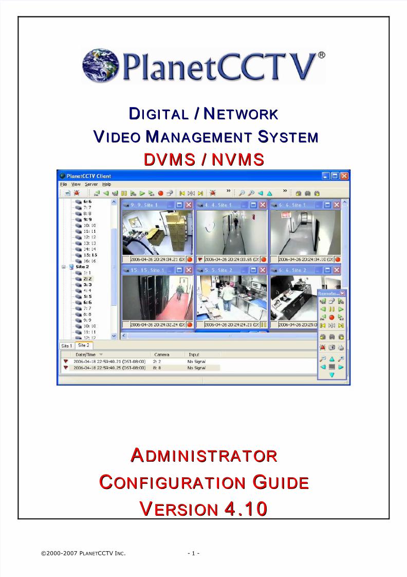
DD IIGGII TTAALL // NNEETTWWOORRKK
VV II DDEEOO MMAANNAAGGEEMMEENNTT SSYYSSTTEEMM
DDVVMMSS // NNVVMMSS
AADDMMIINN IISSTTRRAATTOORR
CCOONNFFIIGGUURRAATT IIOONN GGUUIIDDEE
VVEERRSSIIOONN 44 ..1100
8/4/2019 PlanetCCTV Configuration Guide Ver 4
http://slidepdf.com/reader/full/planetcctv-configuration-guide-ver-4 2/72
©2000-2007 PLANETCCTV INC. - 2 -
8/4/2019 PlanetCCTV Configuration Guide Ver 4
http://slidepdf.com/reader/full/planetcctv-configuration-guide-ver-4 3/72
©2000-2007 PLANETCCTV INC. - 3 -
Plane t CCTV DVMS/NVMS Adm inis t rat or
Conf igurat ion Guide v4.1
About this guide
The PlanetCCTV Software Suite (P lanetCCTV®) is a comprehensive solution
for digitally capturing, compressing and storing CCTV camera images.
PlanetCCTV digital recording systems are available for traditional ana log (CCD)camera systems or I P/ n et w o r k ca m e r a systems, or a combination of bothtechnologies known as h y b r i d systems.
Intended audience
The PlanetCCTV Conf igur a t io n Guide is intended for Administrators as aguide to configuring the PlanetCCTV system.
This guide assumes that the Administrator has a basic knowledge of Windows2000 and Windows XP Professional.
Using this guide
The following topics are covered
• Chapter 1: Configuration of the PlanetCCTV Server Control Panel A description of how to set up and customize your configurable options viathe PlanetCCTV Server Control Panel.
• Chapter 2: Configuration of the PlanetCCTV Basestation Control Panel A description of how to set up and customize your configurable options viathe PlanetCCTV Basestation Control Panel.
• Chapter 3: Configuration of the PlanetCCTV Server Service A description of how to set up the PlanetCCTV server.
• Chapter 4: Configuration of the PlanetCCTV Remote Access ServerA description of how to set up and customize remote access to the
PlanetCCTV system.
• Appendices: Includes a list of error codes and other specifications
8/4/2019 PlanetCCTV Configuration Guide Ver 4
http://slidepdf.com/reader/full/planetcctv-configuration-guide-ver-4 4/72
©2000-2007 PLANETCCTV INC. - 4 -
INDEX
• Chapter 1: CONFIGURATION OF THE PLANETCCTV SERVER CONTROL PANEL 5
o PlanetCCTV Server Control Panel: GENERAL 5
o PlanetCCTV Server Control Panel: CAMERAS 6 General Tab 7 Images Tab 8
o Recording Options 10o Video Motion Detection 12
Alarms Tab 15 PTZ Tab 16
o Presets 18 Users Tab 20 Copying Camera Settings between Cameras 21
o PlanetCCTV Server Control Panel: I/ O 24o PlanetCCTV Server Control Panel: PTZ 30o PlanetCCTV Server Control Panel: USERS 32
o PlanetCCTV Server Control Panel: ARCHIVE 33o PlanetCCTV Server Control Panel: ADVANCED 35
o PlanetCCTV Server Control Panel: ADVANCED-NOTIFICATIONS 36
o PlanetCCTV Server Control Panel: ADVANCED-BASESTATION 39
o PlanetCCTV Server Control Panel: ADVANCED-HTTP 40o PlanetCCTV Server Control Panel: ADVANCED-EXT. MONI TOR 41o PlanetCCTV Server Control Panel: MAPS 43o PlanetCCTV Server Control Panel: SERVICE 45
• Chapter 2: CONFIGURATION OF THE PLANETCCTV BASESTATION CONTROL PANEL 47
o PlanetCCTV Basestation Control Panel: GENERAL 47
o PlanetCCTV Basestation Control Panel: SERVERS 48o PlanetCCTV Basestation Control Panel: USERS 50o PlanetCCTV Basestation Control Panel: SERVICE 51
• Chapter 3: CONFIGURATION OF THE PLANETCCTV SERVER SERVICE 53
• Chapter 4: CONFIGURATION OF THE PLANETCCTV REMOTE ACCESS SERVER 59
• Appendices: INCLUDES A LIST OF ERROR CODES AND OTHER SPECIFICATIONS 67
8/4/2019 PlanetCCTV Configuration Guide Ver 4
http://slidepdf.com/reader/full/planetcctv-configuration-guide-ver-4 5/72
©2000-2007 PLANETCCTV INC. - 5 -
Chapter 1: Configuration of the PlanetCCTVServer Control Panel
IntroductionThis chapter introduces the PlanetCCTV Configuration software for systemadministrators of PlanetCCTV.
The PlanetCCTV Control Panel can be found in the Windows Control Panel or
under the Server Context menu options (right-click menu) within thePlanetCCTV Client.
PlanetCCTV Server Control Panel: General
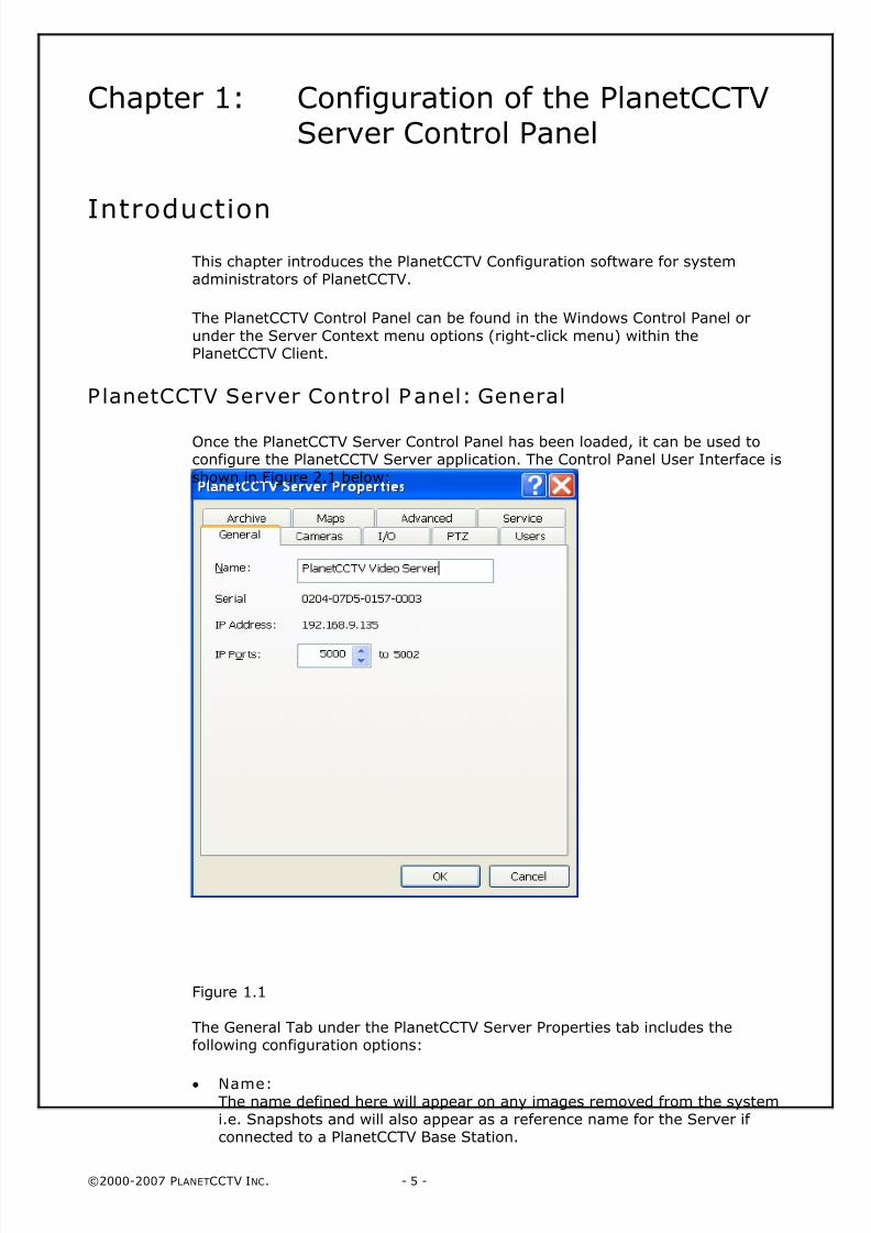
Once the PlanetCCTV Server Control Panel has been loaded, it can be used toconfigure the PlanetCCTV Server application. The Control Panel User Interface is
shown in Figure 2.1 below:
Figure 1.1
The General Tab under the PlanetCCTV Server Properties tab includes thefollowing configuration options:
• Name: The name defined here will appear on any images removed from the systemi.e. Snapshots and will also appear as a reference name for the Server if connected to a PlanetCCTV Base Station.
8/4/2019 PlanetCCTV Configuration Guide Ver 4
http://slidepdf.com/reader/full/planetcctv-configuration-guide-ver-4 6/72
©2000-2007 PLANETCCTV INC. - 6 -
• Serial Number:The Serial Number displayed here is the hard coded number that appears in
the I-Button attached to the Parallel Port of the Server.
• IP Address:IP address of the DVR Server.
• IP P orts:
TCP/IP Port Numbers used by the server. These should be set in conjunctionwith the Firewall Administrator so that these ports can be enabled on anyFirewalls between the Client and the Server.
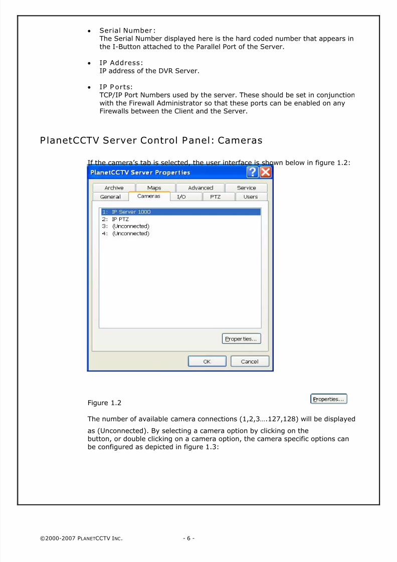
PlanetCCTV Server Control Panel: Cameras
If the camera’s tab is selected, the user interface is shown below in figure 1.2:
Figure 1.2
The number of available camera connections (1,2,3….127,128) will be displayed
as (Unconnected). By selecting a camera option by clicking on thebutton, or double clicking on a camera option, the camera specific options canbe configured as depicted in figure 1.3:
8/4/2019 PlanetCCTV Configuration Guide Ver 4
http://slidepdf.com/reader/full/planetcctv-configuration-guide-ver-4 7/72
©2000-2007 PLANETCCTV INC. - 7 -
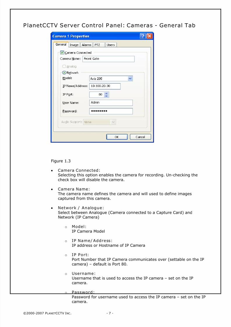
PlanetCCTV Server Control Panel: Cameras - General Tab
Figure 1.3
•
Camera Connected:Selecting this option enables the camera for recording. Un-checking the
check box will disable the camera.
• Camera Name:The camera name defines the camera and will used to define imagescaptured from this camera.
• Network / Analogue:
Select between Analogue (Camera connected to a Capture Card) andNetwork (IP Camera)
o Model:IP Camera Model
o IP Name/ Address:
IP address or Hostname of IP Camera
o IP Port: Port Number that IP Camera communicates over (settable on the IPcamera) – default is Port 80.
o Username: Username that is used to access the IP camera – set on the IPcamera.
o Password:
Password for username used to access the IP camera – set on the IPcamera.
8/4/2019 PlanetCCTV Configuration Guide Ver 4
http://slidepdf.com/reader/full/planetcctv-configuration-guide-ver-4 8/72
©2000-2007 PLANETCCTV INC. - 8 -
• Audio Support:The audio support option are none, 1 way record or 2 way audio link. 1 way
audio records the audio for the selected camera on the server. 2 way audioenables 2 way audio link between client and server. The 2 way audio link isnot recorded.
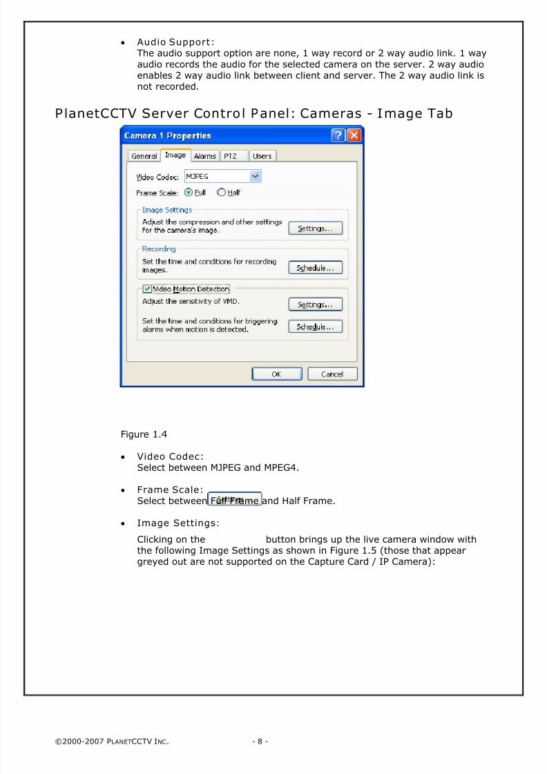
PlanetCCTV Server Control Panel: Cameras - Image Tab
Figure 1.4
• Video Codec:Select between MJPEG and MPEG4.
• Frame Scale:Select between Full Frame and Half Frame.
• Image Settings:
Clicking on the button brings up the live camera window withthe following Image Settings as shown in Figure 1.5 (those that appeargreyed out are not supported on the Capture Card / IP Camera):
8/4/2019 PlanetCCTV Configuration Guide Ver 4
http://slidepdf.com/reader/full/planetcctv-configuration-guide-ver-4 9/72
©2000-2007 PLANETCCTV INC. - 9 -
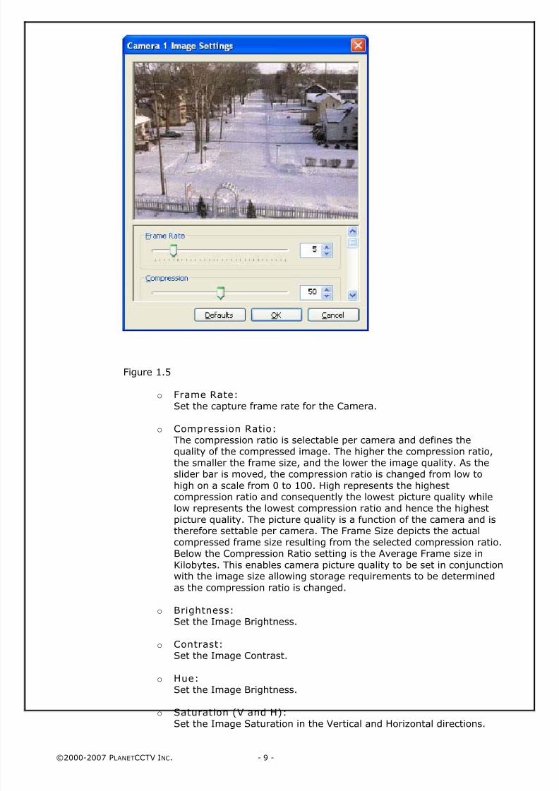
Figure 1.5
o Frame Rate:
Set the capture frame rate for the Camera.
o Compression Ratio:The compression ratio is selectable per camera and defines thequality of the compressed image. The higher the compression ratio,the smaller the frame size, and the lower the image quality. As theslider bar is moved, the compression ratio is changed from low to
high on a scale from 0 to 100. High represents the highestcompression ratio and consequently the lowest picture quality whilelow represents the lowest compression ratio and hence the highestpicture quality. The picture quality is a function of the camera and istherefore settable per camera. The Frame Size depicts the actualcompressed frame size resulting from the selected compression ratio.
Below the Compression Ratio setting is the Average Frame size inKilobytes. This enables camera picture quality to be set in conjunctionwith the image size allowing storage requirements to be determined
as the compression ratio is changed.
o Brightness:Set the Image Brightness.
o Contrast:Set the Image Contrast.
o Hue:
Set the Image Brightness.
o Saturation (V and H):Set the Image Saturation in the Vertical and Horizontal directions.
8/4/2019 PlanetCCTV Configuration Guide Ver 4
http://slidepdf.com/reader/full/planetcctv-configuration-guide-ver-4 10/72
©2000-2007 PLANETCCTV INC. - 10 -
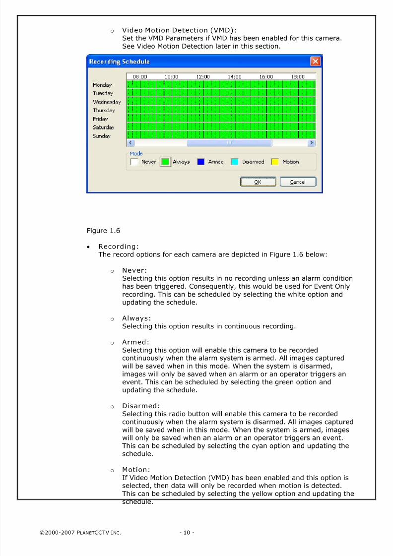
o Video Motion Detection (VMD): Set the VMD Parameters if VMD has been enabled for this camera.
See Video Motion Detection later in this section.
Figure 1.6
• Recording:The record options for each camera are depicted in Figure 1.6 below:
o Never:Selecting this option results in no recording unless an alarm conditionhas been triggered. Consequently, this would be used for Event Only
recording. This can be scheduled by selecting the white option andupdating the schedule.
o Always: Selecting this option results in continuous recording.
o Armed:
Selecting this option will enable this camera to be recordedcontinuously when the alarm system is armed. All images captured
will be saved when in this mode. When the system is disarmed,images will only be saved when an alarm or an operator triggers anevent. This can be scheduled by selecting the green option and
updating the schedule.
o Disarmed:Selecting this radio button will enable this camera to be recorded
continuously when the alarm system is disarmed. All images capturedwill be saved when in this mode. When the system is armed, imageswill only be saved when an alarm or an operator triggers an event.This can be scheduled by selecting the cyan option and updating theschedule.
o Motion:
If Video Motion Detection (VMD) has been enabled and this option is
selected, then data will only be recorded when motion is detected.This can be scheduled by selecting the yellow option and updating theschedule.
8/4/2019 PlanetCCTV Configuration Guide Ver 4
http://slidepdf.com/reader/full/planetcctv-configuration-guide-ver-4 11/72
©2000-2007 PLANETCCTV INC. - 11 -
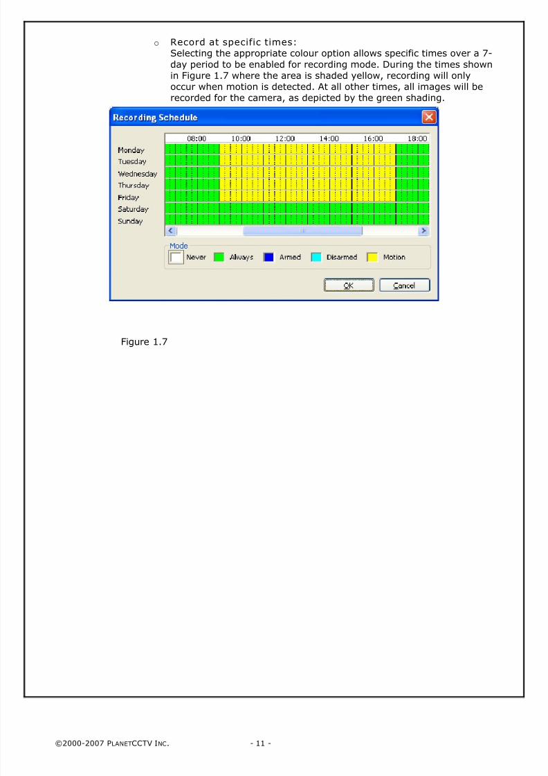
o Record at specific times:Selecting the appropriate colour option allows specific times over a 7-
day period to be enabled for recording mode. During the times shownin Figure 1.7 where the area is shaded yellow, recording will onlyoccur when motion is detected. At all other times, all images will berecorded for the camera, as depicted by the green shading.
Figure 1.7
8/4/2019 PlanetCCTV Configuration Guide Ver 4
http://slidepdf.com/reader/full/planetcctv-configuration-guide-ver-4 12/72
©2000-2007 PLANETCCTV INC. - 12 -
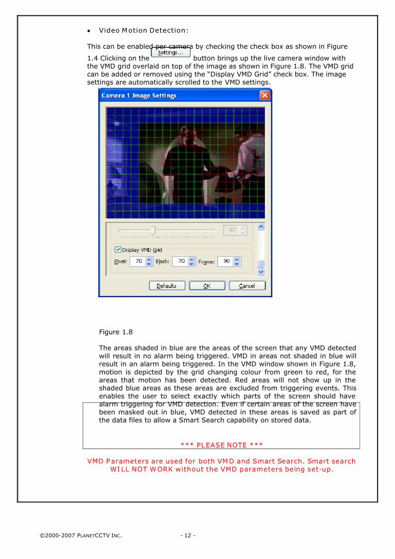
• Video Motion Detection:
This can be enabled per camera by checking the check box as shown in Figure
1.4 Clicking on the button brings up the live camera window withthe VMD grid overlaid on top of the image as shown in Figure 1.8. The VMD gridcan be added or removed using the “Display VMD Grid” check box. The imagesettings are automatically scrolled to the VMD settings.
Figure 1.8
The areas shaded in blue are the areas of the screen that any VMD detectedwill result in no alarm being triggered. VMD in areas not shaded in blue willresult in an alarm being triggered. In the VMD window shown in Figure 1.8,
motion is depicted by the grid changing colour from green to red, for theareas that motion has been detected. Red areas will not show up in theshaded blue areas as these areas are excluded from triggering events. Thisenables the user to select exactly which parts of the screen should havealarm triggering for VMD detection. Even if certain areas of the screen havebeen masked out in blue, VMD detected in these areas is saved as part of the data files to allow a Smart Search capability on stored data.
*** PLEASE NOTE ***
VMD Parameters are used for both VMD and Smart Search. Smart searchWI LL NOT WORK without the VMD parameters being set-up.
8/4/2019 PlanetCCTV Configuration Guide Ver 4
http://slidepdf.com/reader/full/planetcctv-configuration-guide-ver-4 13/72
©2000-2007 PLANETCCTV INC. - 13 -
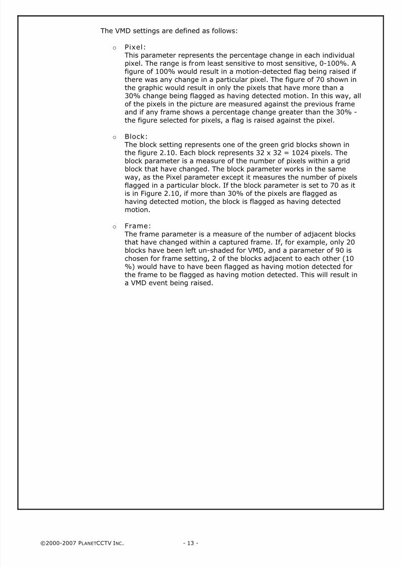
The VMD settings are defined as follows:
o Pixel:This parameter represents the percentage change in each individualpixel. The range is from least sensitive to most sensitive, 0-100%. Afigure of 100% would result in a motion-detected flag being raised if there was any change in a particular pixel. The figure of 70 shown inthe graphic would result in only the pixels that have more than a
30% change being flagged as having detected motion. In this way, allof the pixels in the picture are measured against the previous frameand if any frame shows a percentage change greater than the 30% -
the figure selected for pixels, a flag is raised against the pixel.
o Block:The block setting represents one of the green grid blocks shown inthe figure 2.10. Each block represents 32 x 32 = 1024 pixels. Theblock parameter is a measure of the number of pixels within a gridblock that have changed. The block parameter works in the same
way, as the Pixel parameter except it measures the number of pixelsflagged in a particular block. If the block parameter is set to 70 as itis in Figure 2.10, if more than 30% of the pixels are flagged ashaving detected motion, the block is flagged as having detectedmotion.
o Frame:
The frame parameter is a measure of the number of adjacent blocksthat have changed within a captured frame. If, for example, only 20
blocks have been left un-shaded for VMD, and a parameter of 90 ischosen for frame setting, 2 of the blocks adjacent to each other (10%) would have to have been flagged as having motion detected forthe frame to be flagged as having motion detected. This will result ina VMD event being raised.
8/4/2019 PlanetCCTV Configuration Guide Ver 4
http://slidepdf.com/reader/full/planetcctv-configuration-guide-ver-4 14/72
©2000-2007 PLANETCCTV INC. - 14 -
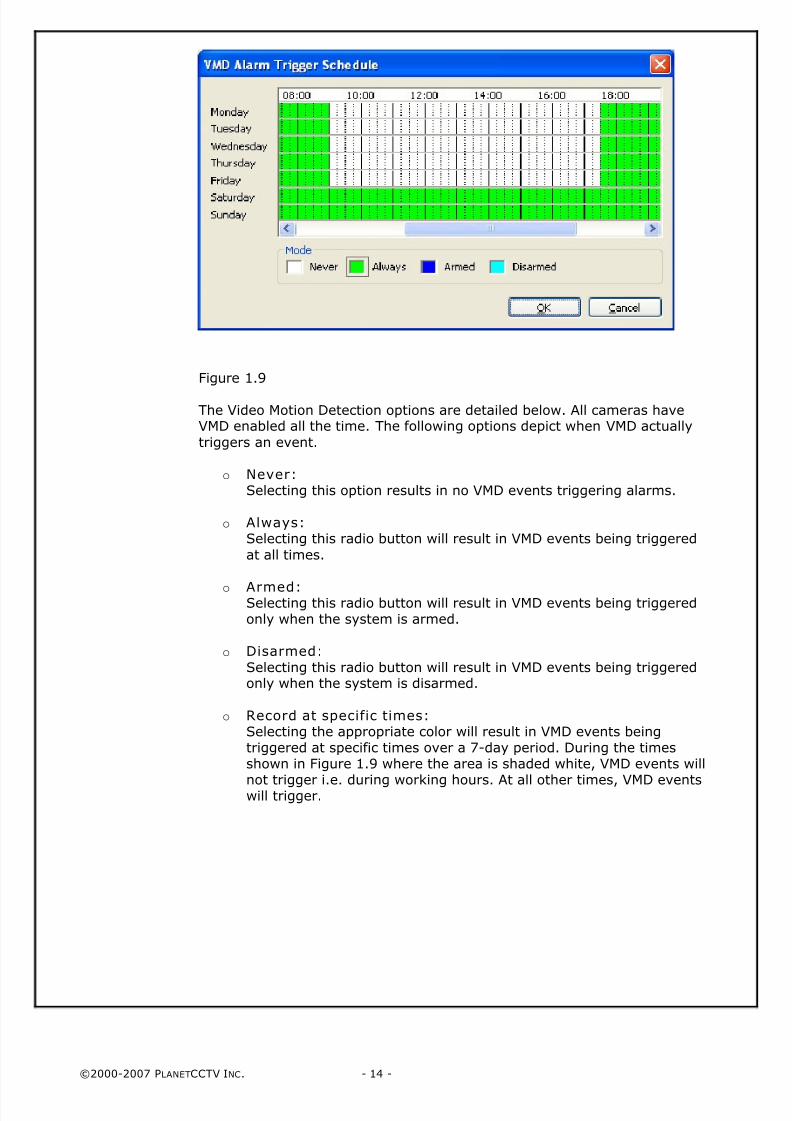
Figure 1.9
The Video Motion Detection options are detailed below. All cameras haveVMD enabled all the time. The following options depict when VMD actually
triggers an event.
o Never:Selecting this option results in no VMD events triggering alarms.
o Always:Selecting this radio button will result in VMD events being triggered
at all times.
o Armed: Selecting this radio button will result in VMD events being triggeredonly when the system is armed.
o Disarmed:
Selecting this radio button will result in VMD events being triggeredonly when the system is disarmed.
o Record at specific times:Selecting the appropriate color will result in VMD events beingtriggered at specific times over a 7-day period. During the timesshown in Figure 1.9 where the area is shaded white, VMD events will
not trigger i.e. during working hours. At all other times, VMD eventswill trigger.
8/4/2019 PlanetCCTV Configuration Guide Ver 4
http://slidepdf.com/reader/full/planetcctv-configuration-guide-ver-4 15/72
©2000-2007 PLANETCCTV INC. - 15 -
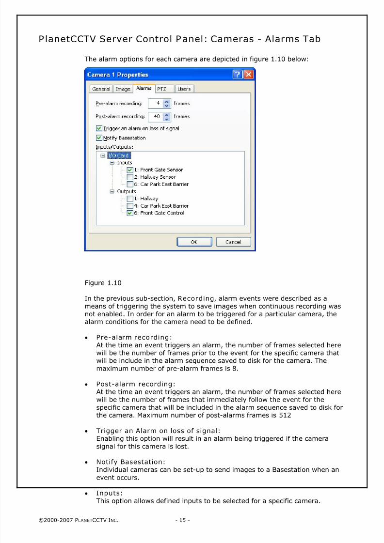
PlanetCCTV Server Control Panel: Cameras - Alarms Tab
The alarm options for each camera are depicted in figure 1.10 below:
Figure 1.10
In the previous sub-section, Recording, alarm events were described as ameans of triggering the system to save images when continuous recording wasnot enabled. In order for an alarm to be triggered for a particular camera, thealarm conditions for the camera need to be defined.
• Pre-alarm recording:At the time an event triggers an alarm, the number of frames selected here
will be the number of frames prior to the event for the specific camera thatwill be include in the alarm sequence saved to disk for the camera. The
maximum number of pre-alarm frames is 8.
• Post-alarm recording:At the time an event triggers an alarm, the number of frames selected herewill be the number of frames that immediately follow the event for the
specific camera that will be included in the alarm sequence saved to disk forthe camera. Maximum number of post-alarms frames is 512
• Trigger an Alarm on loss of signal:Enabling this option will result in an alarm being triggered if the camerasignal for this camera is lost.
• Notify Basestation:Individual cameras can be set-up to send images to a Basestation when an
event occurs.
• Inputs:This option allows defined inputs to be selected for a specific camera.
8/4/2019 PlanetCCTV Configuration Guide Ver 4
http://slidepdf.com/reader/full/planetcctv-configuration-guide-ver-4 16/72
©2000-2007 PLANETCCTV INC. - 16 -
• Outputs:This option allows defined outputs to be selected for a specific camera.
A camera can have multiple inputs and outputs. Inputs and Outputs can beassigned to more than one camera. Figure 2.5 shows one input and one outputselected for camera 1.
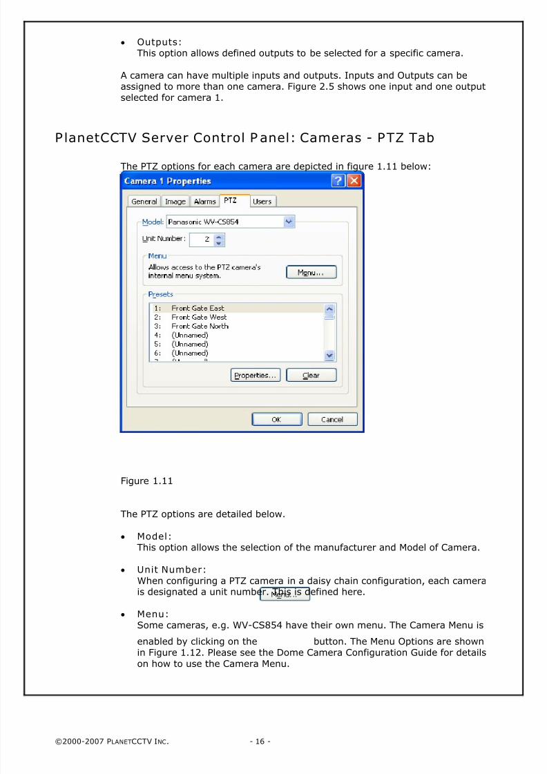
PlanetCCTV Server Control P anel: Cameras - PTZ Tab
The PTZ options for each camera are depicted in figure 1.11 below:
Figure 1.11
The PTZ options are detailed below.
• Model:This option allows the selection of the manufacturer and Model of Camera.
• Unit Number:
When configuring a PTZ camera in a daisy chain configuration, each camerais designated a unit number. This is defined here.
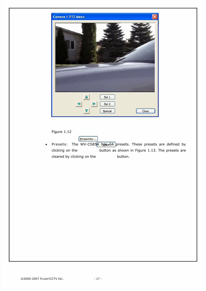
• Menu:Some cameras, e.g. WV-CS854 have their own menu. The Camera Menu is
enabled by clicking on the button. The Menu Options are shownin Figure 1.12. Please see the Dome Camera Configuration Guide for details
on how to use the Camera Menu.
8/4/2019 PlanetCCTV Configuration Guide Ver 4
http://slidepdf.com/reader/full/planetcctv-configuration-guide-ver-4 17/72
©2000-2007 PLANETCCTV INC. - 17 -
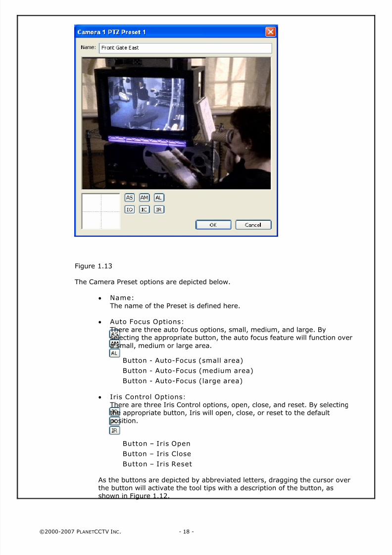
Figure 1.12
• Presets: The WV-CS854 has 64 presets. These presets are defined by
clicking on the button as shown in Figure 1.13. The presets are
cleared by clicking on the button.
8/4/2019 PlanetCCTV Configuration Guide Ver 4
http://slidepdf.com/reader/full/planetcctv-configuration-guide-ver-4 18/72
©2000-2007 PLANETCCTV INC. - 18 -
Figure 1.13
The Camera Preset options are depicted below.
• Name:
The name of the Preset is defined here.
• Auto Focus Options:There are three auto focus options, small, medium, and large. Byselecting the appropriate button, the auto focus feature will function over
a small, medium or large area.
Button - Auto-Focus (small area)
Button - Auto-Focus (medium area)
Button - Auto-Focus (large area)
• Iris Control Options:There are three Iris Control options, open, close, and reset. By selectingthe appropriate button, Iris will open, close, or reset to the defaultposition.
Button – Iris Open
Button – Iris Close
Button – Iris Reset
As the buttons are depicted by abbreviated letters, dragging the cursor over
the button will activate the tool tips with a description of the button, asshown in Figure 1.12.
8/4/2019 PlanetCCTV Configuration Guide Ver 4
http://slidepdf.com/reader/full/planetcctv-configuration-guide-ver-4 19/72
©2000-2007 PLANETCCTV INC. - 19 -
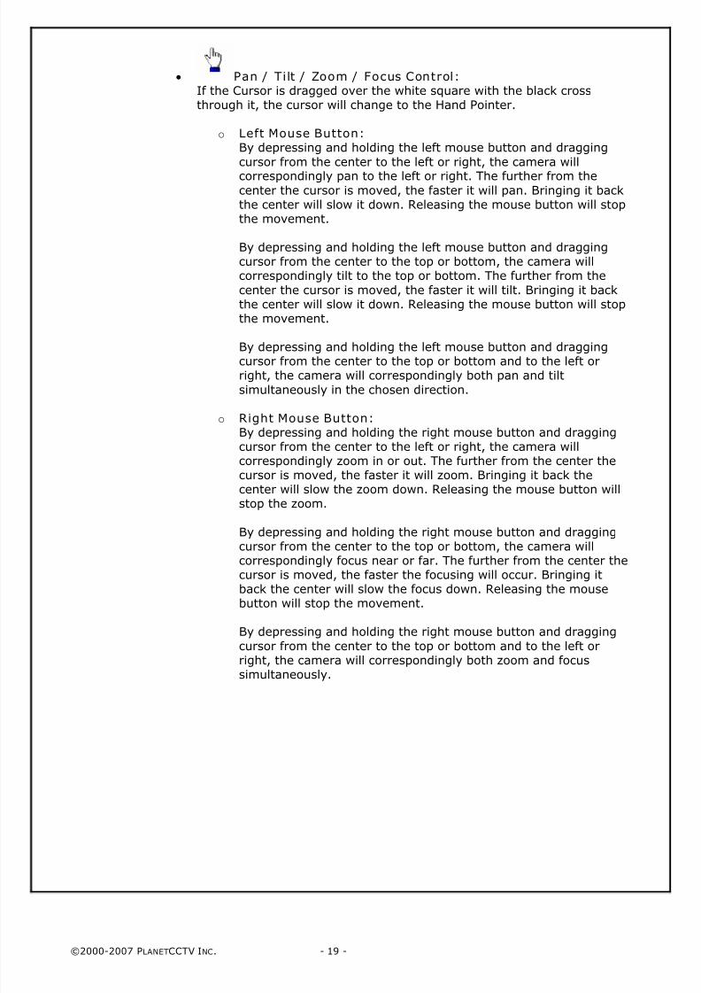
• Pan / Tilt / Zoom / Focus Control:If the Cursor is dragged over the white square with the black crossthrough it, the cursor will change to the Hand Pointer.
o Left Mouse Button:By depressing and holding the left mouse button and dragging
cursor from the center to the left or right, the camera will
correspondingly pan to the left or right. The further from thecenter the cursor is moved, the faster it will pan. Bringing it backthe center will slow it down. Releasing the mouse button will stopthe movement.
By depressing and holding the left mouse button and draggingcursor from the center to the top or bottom, the camera willcorrespondingly tilt to the top or bottom. The further from the
center the cursor is moved, the faster it will tilt. Bringing it backthe center will slow it down. Releasing the mouse button will stopthe movement.
By depressing and holding the left mouse button and draggingcursor from the center to the top or bottom and to the left orright, the camera will correspondingly both pan and tilt
simultaneously in the chosen direction.
o Right Mouse Button:By depressing and holding the right mouse button and draggingcursor from the center to the left or right, the camera willcorrespondingly zoom in or out. The further from the center thecursor is moved, the faster it will zoom. Bringing it back thecenter will slow the zoom down. Releasing the mouse button willstop the zoom.
By depressing and holding the right mouse button and draggingcursor from the center to the top or bottom, the camera willcorrespondingly focus near or far. The further from the center thecursor is moved, the faster the focusing will occur. Bringing itback the center will slow the focus down. Releasing the mousebutton will stop the movement.
By depressing and holding the right mouse button and dragging
cursor from the center to the top or bottom and to the left orright, the camera will correspondingly both zoom and focussimultaneously.
8/4/2019 PlanetCCTV Configuration Guide Ver 4
http://slidepdf.com/reader/full/planetcctv-configuration-guide-ver-4 20/72
©2000-2007 PLANETCCTV INC. - 20 -
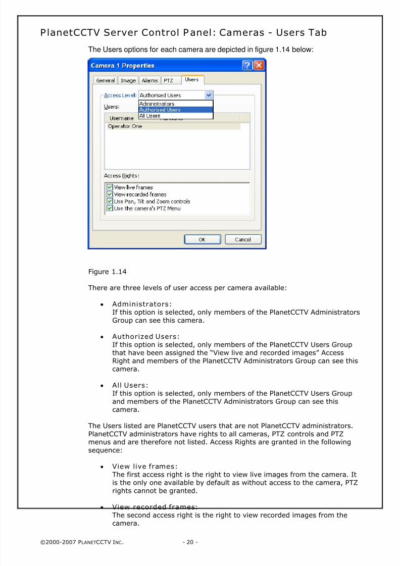
PlanetCCTV Server Control Panel: Cameras - Users Tab
The Users options for each camera are depicted in figure 1.14 below:
Figure 1.14
There are three levels of user access per camera available:
• Administrators:If this option is selected, only members of the PlanetCCTV AdministratorsGroup can see this camera.
• Authorized Users: If this option is selected, only members of the PlanetCCTV Users Groupthat have been assigned the “View live and recorded images” AccessRight and members of the PlanetCCTV Administrators Group can see thiscamera.
• All Users:
If this option is selected, only members of the PlanetCCTV Users Groupand members of the PlanetCCTV Administrators Group can see thiscamera.
The Users listed are PlanetCCTV users that are not PlanetCCTV administrators.
PlanetCCTV administrators have rights to all cameras, PTZ controls and PTZmenus and are therefore not listed. Access Rights are granted in the following
sequence:
• View live frames:The first access right is the right to view live images from the camera. Itis the only one available by default as without access to the camera, PTZrights cannot be granted.
• View recorded frames:The second access right is the right to view recorded images from thecamera.
8/4/2019 PlanetCCTV Configuration Guide Ver 4
http://slidepdf.com/reader/full/planetcctv-configuration-guide-ver-4 21/72
©2000-2007 PLANETCCTV INC. - 21 -
• Use Pan, Tilt and Zoom controls:If the user has been granted rights to view live images from the camera,
the option to use the PTZ functionality can be selected.
• Use the camera’s PTZ Menu:Once PTZ rights have been granted, the option to grant access to thePTZ configuration Menu can be selected.
This completes the set-up for an individual camera.
PlanetCCTV Server Control Panel: Cameras
Copying Camera Settings between Cameras
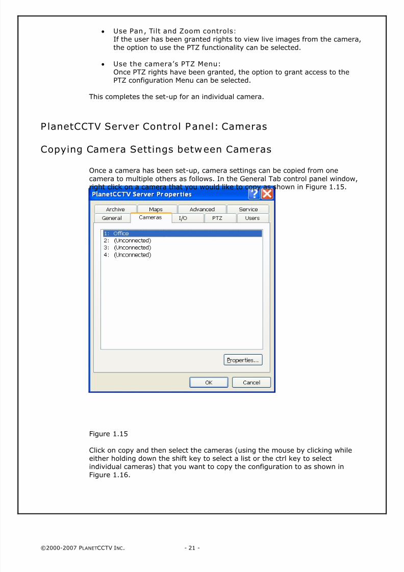
Once a camera has been set-up, camera settings can be copied from one
camera to multiple others as follows. In the General Tab control panel window,right click on a camera that you would like to copy as shown in Figure 1.15.
Figure 1.15
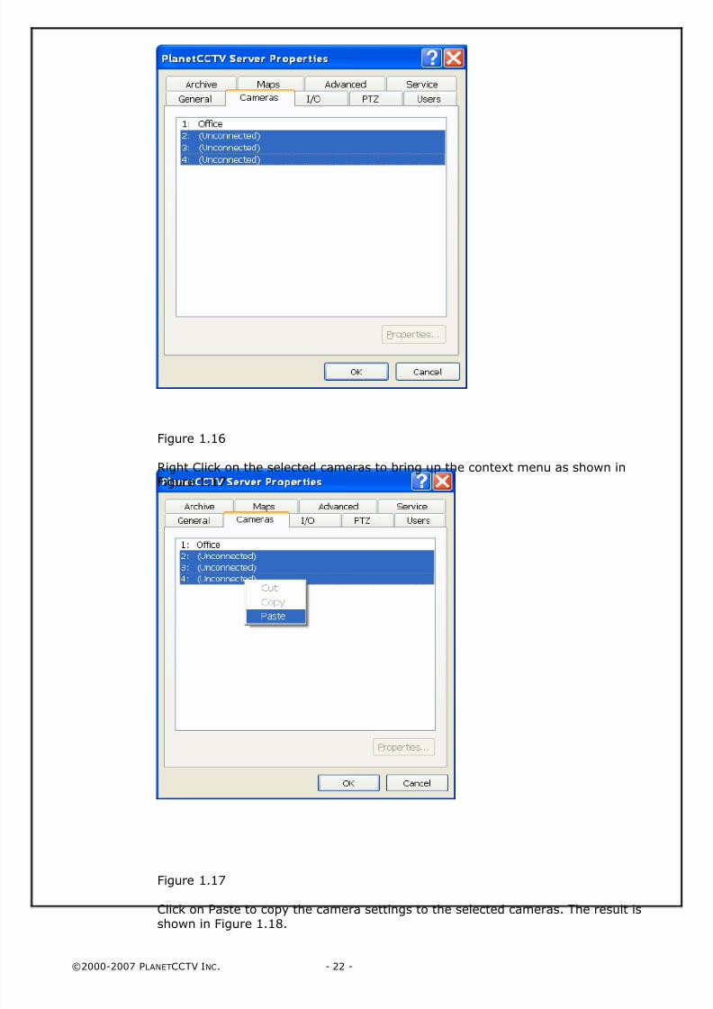
Click on copy and then select the cameras (using the mouse by clicking whileeither holding down the shift key to select a list or the ctrl key to selectindividual cameras) that you want to copy the configuration to as shown inFigure 1.16.
8/4/2019 PlanetCCTV Configuration Guide Ver 4
http://slidepdf.com/reader/full/planetcctv-configuration-guide-ver-4 22/72
©2000-2007 PLANETCCTV INC. - 22 -
Figure 1.16
Right Click on the selected cameras to bring up the context menu as shown inFigure 1.17
Figure 1.17
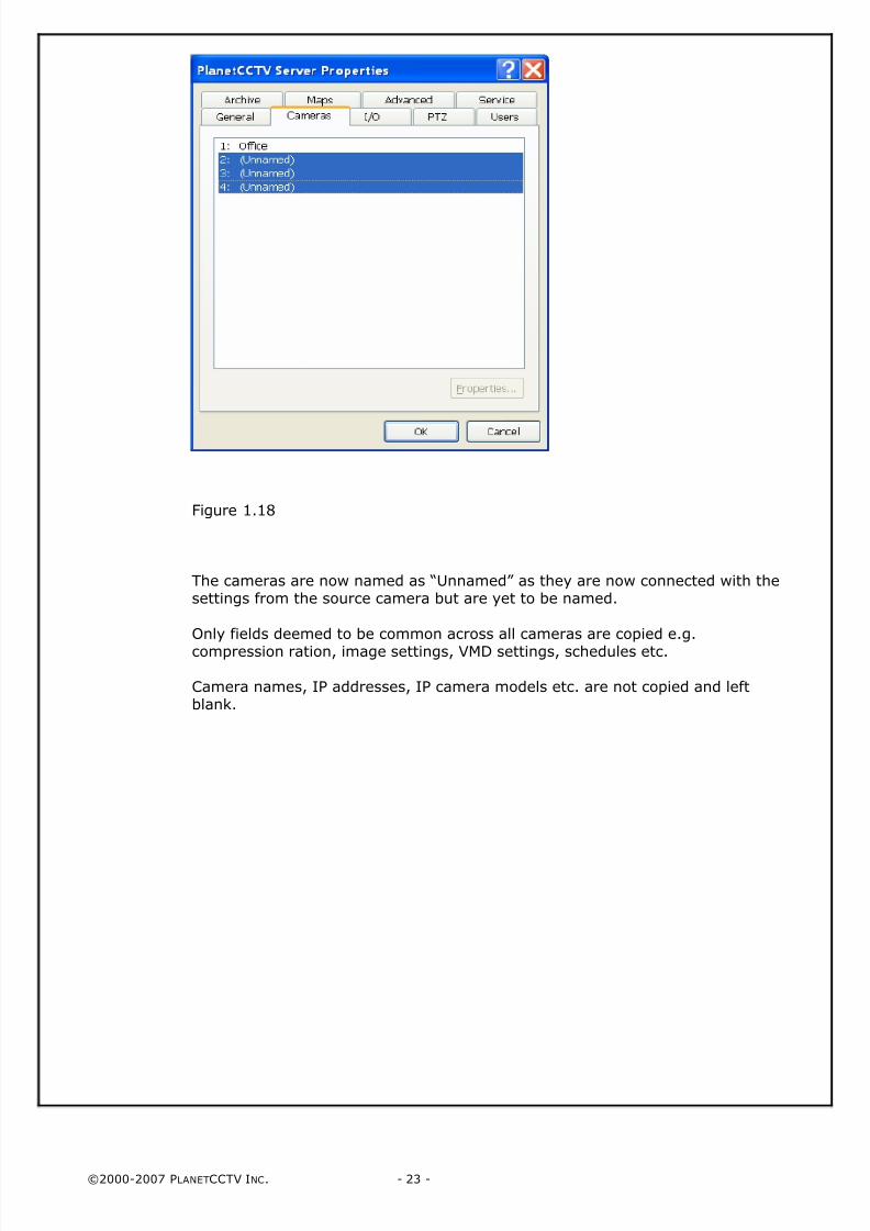
Click on Paste to copy the camera settings to the selected cameras. The result isshown in Figure 1.18.
8/4/2019 PlanetCCTV Configuration Guide Ver 4
http://slidepdf.com/reader/full/planetcctv-configuration-guide-ver-4 23/72
©2000-2007 PLANETCCTV INC. - 23 -
Figure 1.18
The cameras are now named as “Unnamed” as they are now connected with thesettings from the source camera but are yet to be named.
Only fields deemed to be common across all cameras are copied e.g.
compression ration, image settings, VMD settings, schedules etc.
Camera names, IP addresses, IP camera models etc. are not copied and leftblank.
8/4/2019 PlanetCCTV Configuration Guide Ver 4
http://slidepdf.com/reader/full/planetcctv-configuration-guide-ver-4 24/72
©2000-2007 PLANETCCTV INC. - 24 -
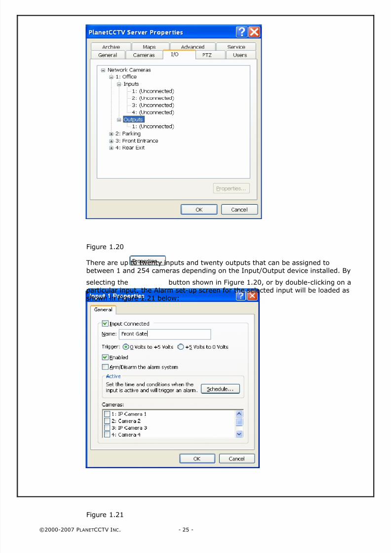
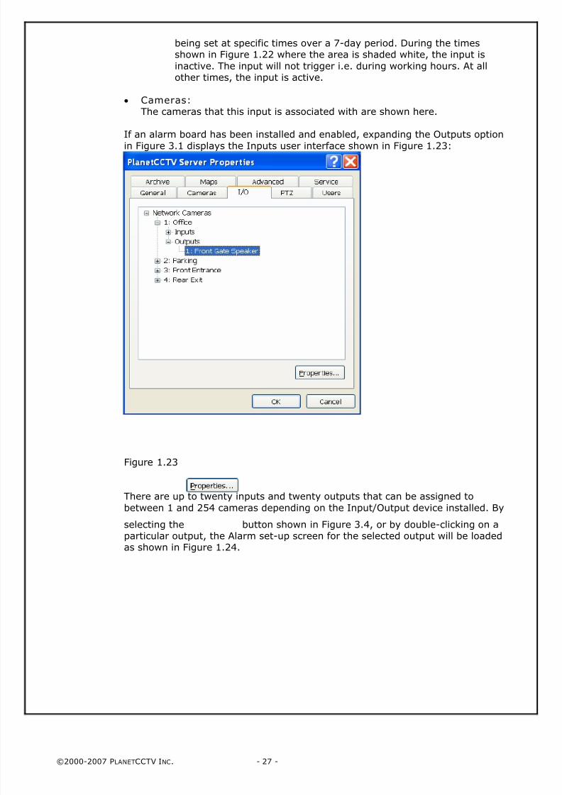
PlanetCCTV Server Control Panel: I/ O
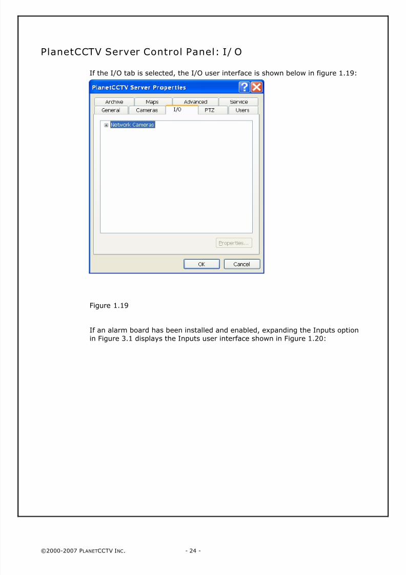
If the I/O tab is selected, the I/O user interface is shown below in figure 1.19:
Figure 1.19
If an alarm board has been installed and enabled, expanding the Inputs option
in Figure 3.1 displays the Inputs user interface shown in Figure 1.20:
8/4/2019 PlanetCCTV Configuration Guide Ver 4
http://slidepdf.com/reader/full/planetcctv-configuration-guide-ver-4 25/72
©2000-2007 PLANETCCTV INC. - 25 -
Figure 1.20
There are up to twenty inputs and twenty outputs that can be assigned tobetween 1 and 254 cameras depending on the Input/Output device installed. By
selecting the button shown in Figure 1.20, or by double-clicking on a
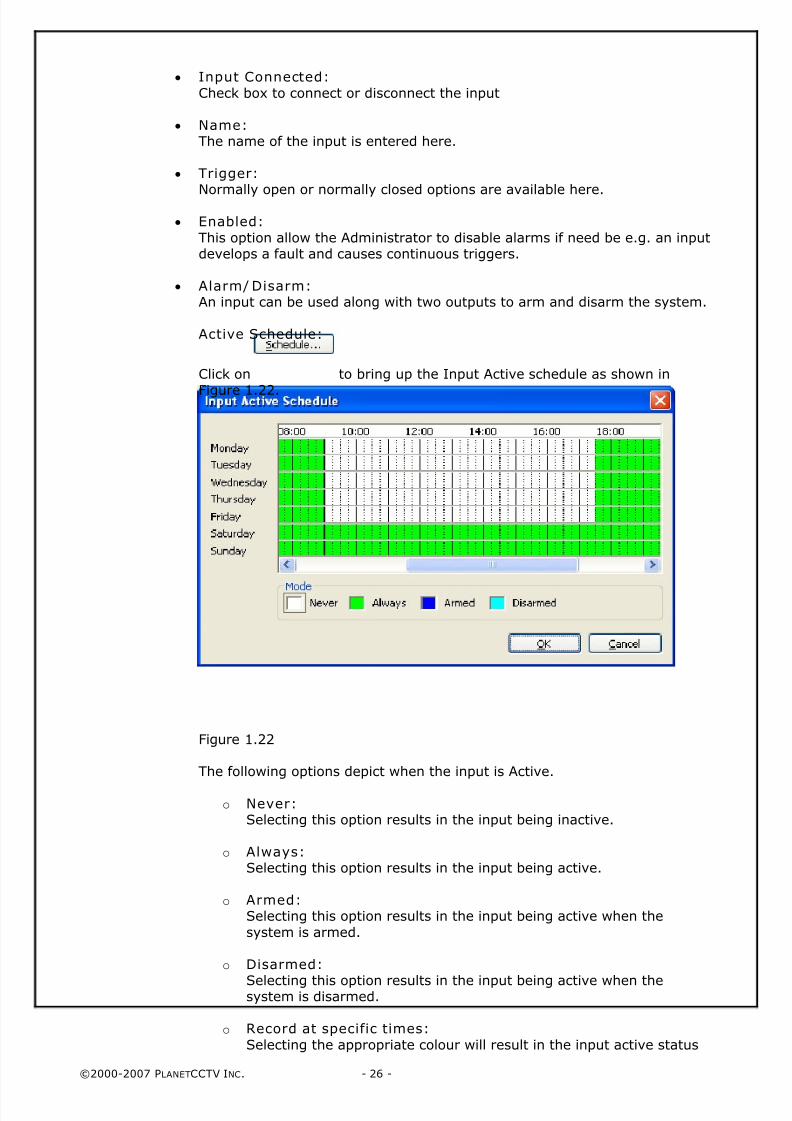
particular input, the Alarm set-up screen for the selected input will be loaded asshown in Figure 1.21 below:
Figure 1.21
8/4/2019 PlanetCCTV Configuration Guide Ver 4
http://slidepdf.com/reader/full/planetcctv-configuration-guide-ver-4 26/72
©2000-2007 PLANETCCTV INC. - 26 -
• Input Connected:
Check box to connect or disconnect the input
• Name:The name of the input is entered here.
• Trigger:
Normally open or normally closed options are available here.
• Enabled:
This option allow the Administrator to disable alarms if need be e.g. an inputdevelops a fault and causes continuous triggers.
• Alarm/ Disarm: An input can be used along with two outputs to arm and disarm the system.
Active Schedule:
Click on to bring up the Input Active schedule as shown in
Figure 1.22.
Figure 1.22
The following options depict when the input is Active.
o Never:Selecting this option results in the input being inactive.
o Always:Selecting this option results in the input being active.
o Armed: Selecting this option results in the input being active when the
system is armed.
o Disarmed:
Selecting this option results in the input being active when thesystem is disarmed.
o Record at specific times:
Selecting the appropriate colour will result in the input active status
8/4/2019 PlanetCCTV Configuration Guide Ver 4
http://slidepdf.com/reader/full/planetcctv-configuration-guide-ver-4 27/72
©2000-2007 PLANETCCTV INC. - 27 -
being set at specific times over a 7-day period. During the timesshown in Figure 1.22 where the area is shaded white, the input is
inactive. The input will not trigger i.e. during working hours. At allother times, the input is active.
• Cameras: The cameras that this input is associated with are shown here.
If an alarm board has been installed and enabled, expanding the Outputs optionin Figure 3.1 displays the Inputs user interface shown in Figure 1.23:
Figure 1.23
There are up to twenty inputs and twenty outputs that can be assigned to
between 1 and 254 cameras depending on the Input/Output device installed. By
selecting the button shown in Figure 3.4, or by double-clicking on aparticular output, the Alarm set-up screen for the selected output will be loadedas shown in Figure 1.24.
8/4/2019 PlanetCCTV Configuration Guide Ver 4
http://slidepdf.com/reader/full/planetcctv-configuration-guide-ver-4 28/72
©2000-2007 PLANETCCTV INC. - 28 -
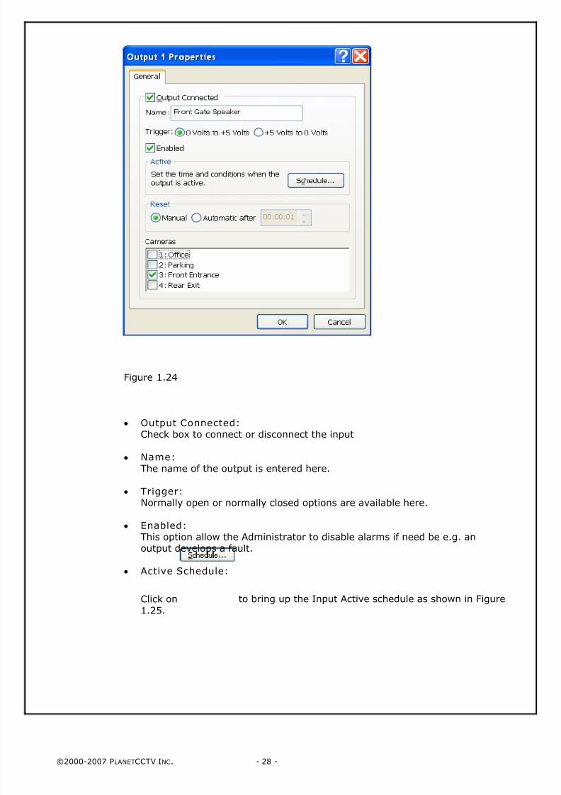
Figure 1.24
• Output Connected:Check box to connect or disconnect the input
• Name:The name of the output is entered here.
• Trigger: Normally open or normally closed options are available here.
• Enabled: This option allow the Administrator to disable alarms if need be e.g. anoutput develops a fault.
• Active Schedule:
Click on to bring up the Input Active schedule as shown in Figure
1.25.
8/4/2019 PlanetCCTV Configuration Guide Ver 4
http://slidepdf.com/reader/full/planetcctv-configuration-guide-ver-4 29/72
©2000-2007 PLANETCCTV INC. - 29 -
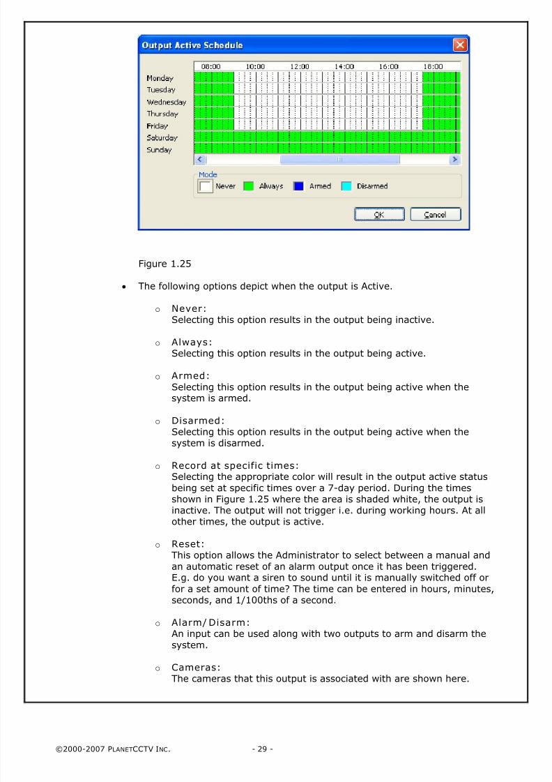
Figure 1.25
• The following options depict when the output is Active.
o Never:Selecting this option results in the output being inactive.
o Always:Selecting this option results in the output being active.
o Armed:
Selecting this option results in the output being active when thesystem is armed.
o Disarmed:Selecting this option results in the output being active when thesystem is disarmed.
o Record at specific times:Selecting the appropriate color will result in the output active status
being set at specific times over a 7-day period. During the timesshown in Figure 1.25 where the area is shaded white, the output isinactive. The output will not trigger i.e. during working hours. At allother times, the output is active.
o
Reset: This option allows the Administrator to select between a manual and
an automatic reset of an alarm output once it has been triggered.E.g. do you want a siren to sound until it is manually switched off or
for a set amount of time? The time can be entered in hours, minutes,seconds, and 1/100ths of a second.
o Alarm/ Disarm: An input can be used along with two outputs to arm and disarm the
system.
o Cameras: The cameras that this output is associated with are shown here.
8/4/2019 PlanetCCTV Configuration Guide Ver 4
http://slidepdf.com/reader/full/planetcctv-configuration-guide-ver-4 30/72
©2000-2007 PLANETCCTV INC. - 30 -
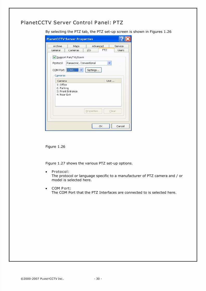
PlanetCCTV Server Control Panel: PTZ
By selecting the PTZ tab, the PTZ set-up screen is shown in Figures 1.26
Figure 1.26
Figure 1.27 shows the various PTZ set-up options.
• Protocol:The protocol or language specific to a manufacturer of PTZ camera and / ormodel is selected here.
• COM P ort:
The COM Port that the PTZ Interfaces are connected to is selected here.
8/4/2019 PlanetCCTV Configuration Guide Ver 4
http://slidepdf.com/reader/full/planetcctv-configuration-guide-ver-4 31/72
©2000-2007 PLANETCCTV INC. - 31 -
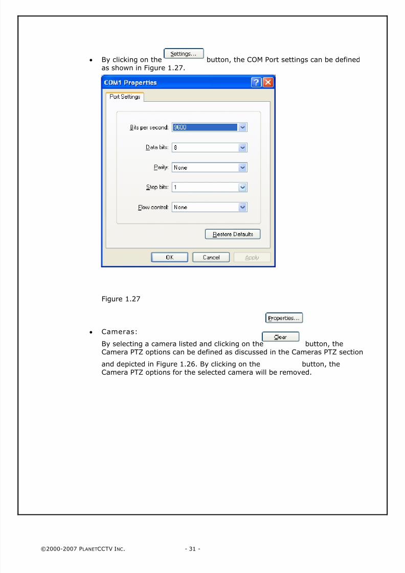
• By clicking on the button, the COM Port settings can be definedas shown in Figure 1.27.
Figure 1.27
• Cameras:
By selecting a camera listed and clicking on the button, theCamera PTZ options can be defined as discussed in the Cameras PTZ section
and depicted in Figure 1.26. By clicking on the button, theCamera PTZ options for the selected camera will be removed.
8/4/2019 PlanetCCTV Configuration Guide Ver 4
http://slidepdf.com/reader/full/planetcctv-configuration-guide-ver-4 32/72
©2000-2007 PLANETCCTV INC. - 32 -
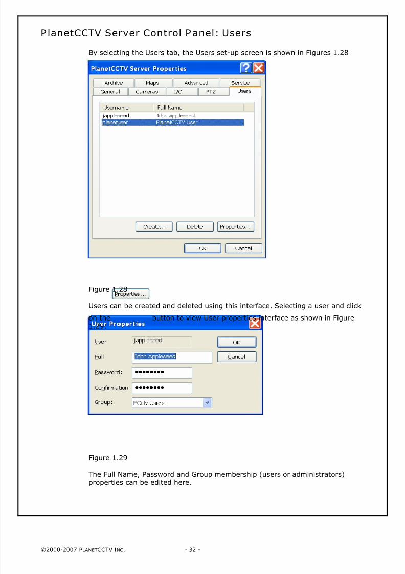
PlanetCCTV Server Control Panel: Users
By selecting the Users tab, the Users set-up screen is shown in Figures 1.28
Figure 1.28
Users can be created and deleted using this interface. Selecting a user and click
on the button to view User properties interface as shown in Figure1.29.
Figure 1.29
The Full Name, Password and Group membership (users or administrators)properties can be edited here.
8/4/2019 PlanetCCTV Configuration Guide Ver 4
http://slidepdf.com/reader/full/planetcctv-configuration-guide-ver-4 33/72
©2000-2007 PLANETCCTV INC. - 33 -
PlanetCCTV Server Control Panel: Archive
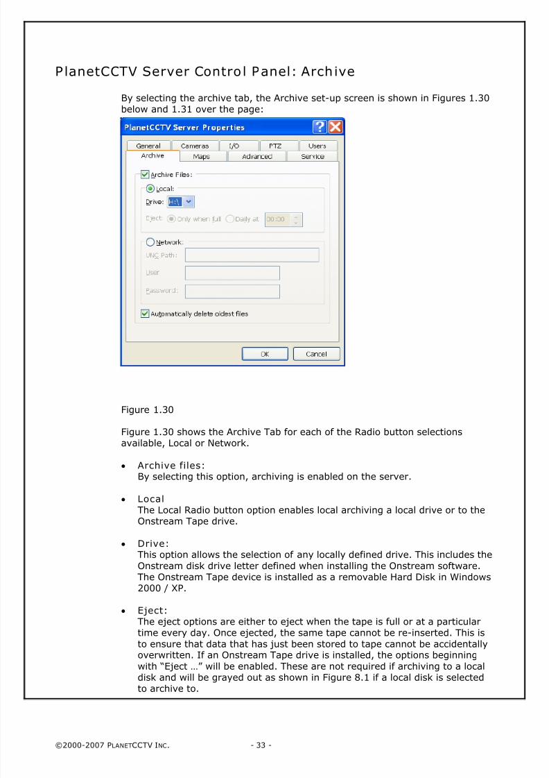
By selecting the archive tab, the Archive set-up screen is shown in Figures 1.30below and 1.31 over the page:
Figure 1.30
Figure 1.30 shows the Archive Tab for each of the Radio button selectionsavailable, Local or Network.
• Archive files:By selecting this option, archiving is enabled on the server.
• LocalThe Local Radio button option enables local archiving a local drive or to theOnstream Tape drive.
• Drive:This option allows the selection of any locally defined drive. This includes the
Onstream disk drive letter defined when installing the Onstream software.The Onstream Tape device is installed as a removable Hard Disk in Windows2000 / XP.
• Eject:The eject options are either to eject when the tape is full or at a particulartime every day. Once ejected, the same tape cannot be re-inserted. This is
to ensure that data that has just been stored to tape cannot be accidentallyoverwritten. If an Onstream Tape drive is installed, the options beginning
with “Eject …” will be enabled. These are not required if archiving to a local
disk and will be grayed out as shown in Figure 8.1 if a local disk is selectedto archive to.
8/4/2019 PlanetCCTV Configuration Guide Ver 4
http://slidepdf.com/reader/full/planetcctv-configuration-guide-ver-4 34/72
©2000-2007 PLANETCCTV INC. - 34 -
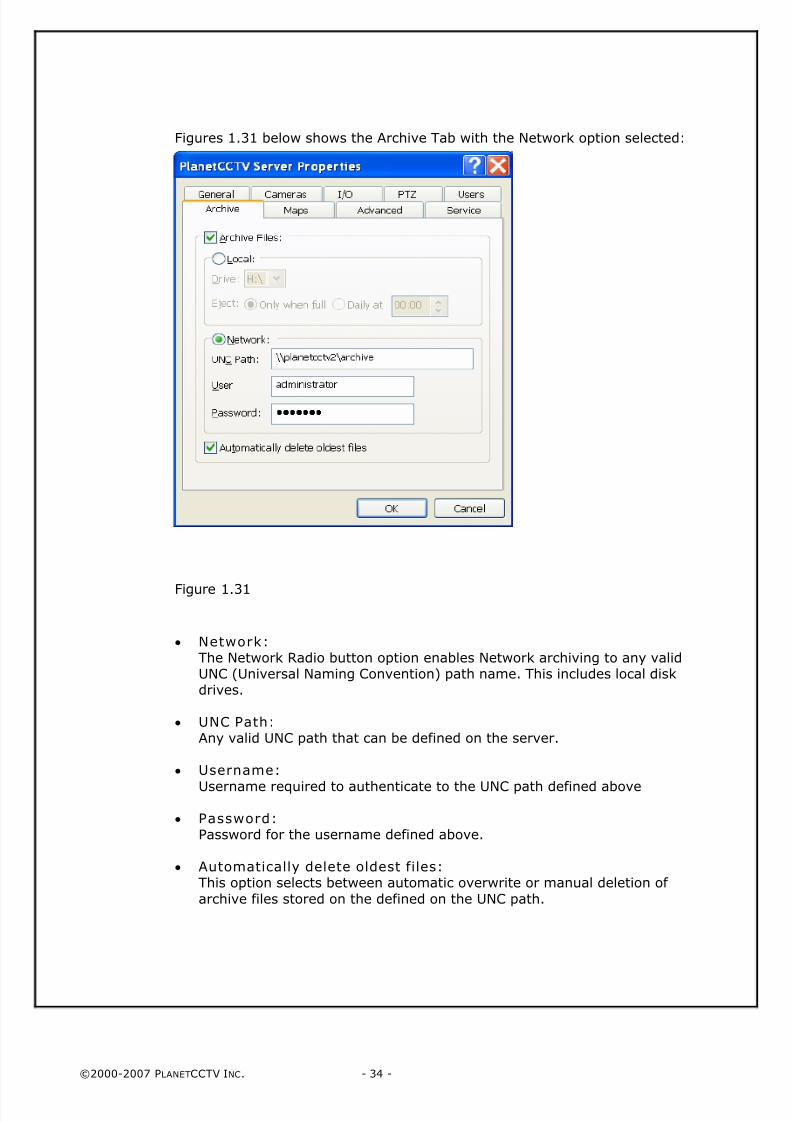
Figures 1.31 below shows the Archive Tab with the Network option selected:
Figure 1.31
• Network:The Network Radio button option enables Network archiving to any validUNC (Universal Naming Convention) path name. This includes local diskdrives.
• UNC Path:Any valid UNC path that can be defined on the server.
• Username:
Username required to authenticate to the UNC path defined above
• Password:Password for the username defined above.
• Automatically delete oldest files: This option selects between automatic overwrite or manual deletion of
archive files stored on the defined on the UNC path.
8/4/2019 PlanetCCTV Configuration Guide Ver 4
http://slidepdf.com/reader/full/planetcctv-configuration-guide-ver-4 35/72
©2000-2007 PLANETCCTV INC. - 35 -
PlanetCCTV Server Control Panel: Advanced
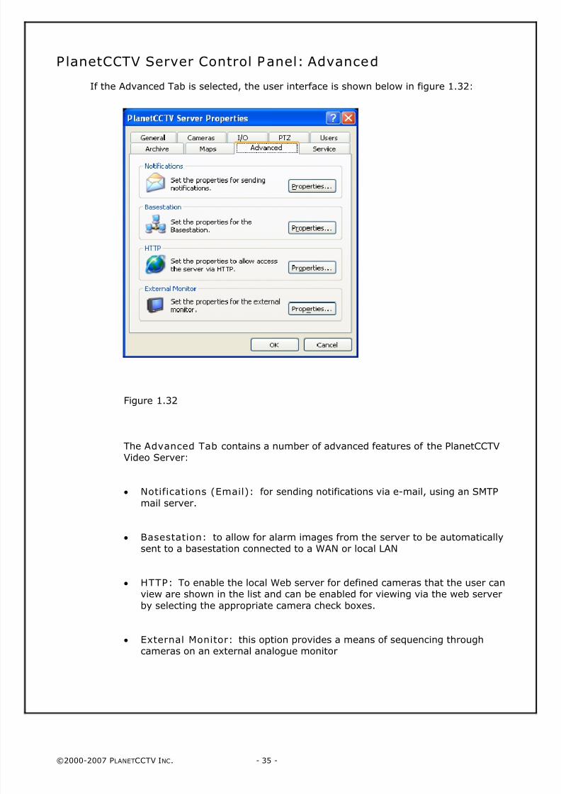
If the Advanced Tab is selected, the user interface is shown below in figure 1.32:
Figure 1.32
The Advanced Tab contains a number of advanced features of the PlanetCCTVVideo Server:
• Notifications (Email): for sending notifications via e-mail, using an SMTP
mail server.
• Basestation: to allow for alarm images from the server to be automaticallysent to a basestation connected to a WAN or local LAN
• HTTP: To enable the local Web server for defined cameras that the user canview are shown in the list and can be enabled for viewing via the web server
by selecting the appropriate camera check boxes.
• External Monitor: this option provides a means of sequencing throughcameras on an external analogue monitor
8/4/2019 PlanetCCTV Configuration Guide Ver 4
http://slidepdf.com/reader/full/planetcctv-configuration-guide-ver-4 36/72
©2000-2007 PLANETCCTV INC. - 36 -
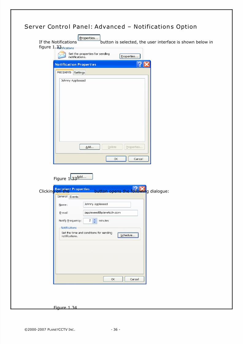
Server Control Panel: Advanced – Notifications Option
If the Notifications button is selected, the user interface is shown below infigure 1.33
Figure 1.33
Clicking on the button opens the following dialogue:
Figure 1.34
8/4/2019 PlanetCCTV Configuration Guide Ver 4
http://slidepdf.com/reader/full/planetcctv-configuration-guide-ver-4 37/72
©2000-2007 PLANETCCTV INC. - 37 -
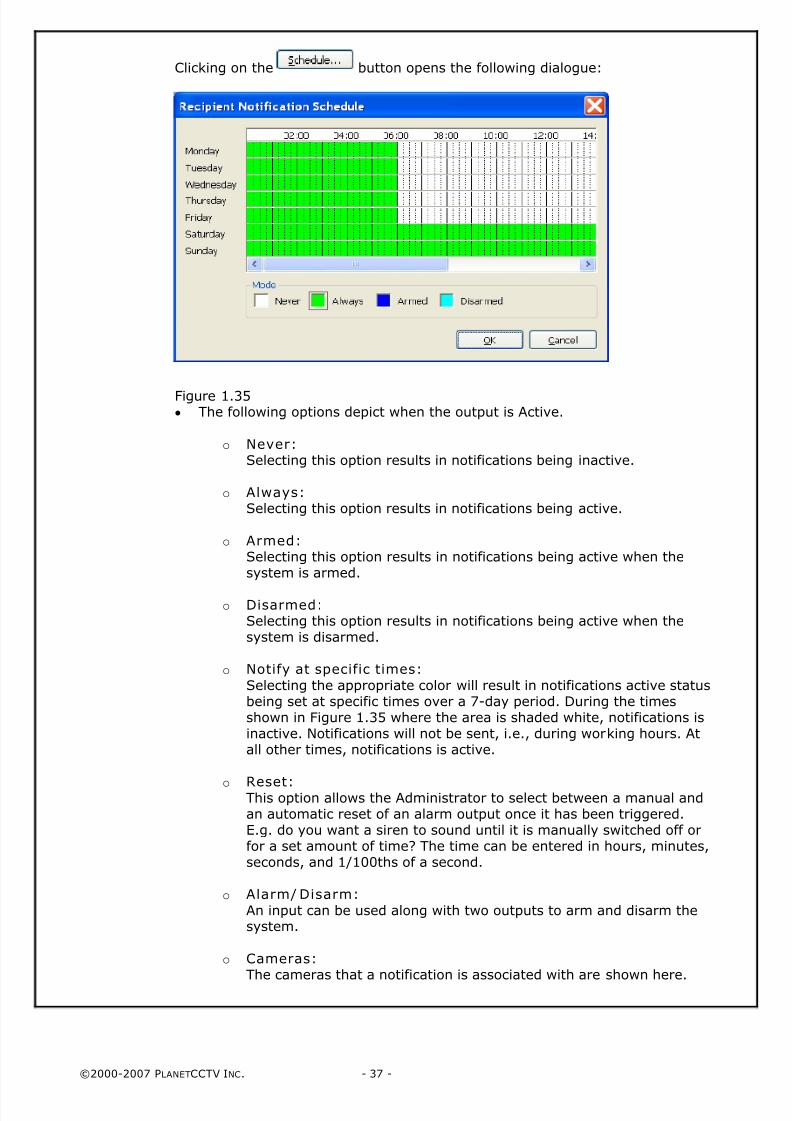
Clicking on the button opens the following dialogue:
Figure 1.35• The following options depict when the output is Active.
o Never:Selecting this option results in notifications being inactive.
o Always:Selecting this option results in notifications being active.
o Armed: Selecting this option results in notifications being active when thesystem is armed.
o Disarmed:Selecting this option results in notifications being active when thesystem is disarmed.
o Notify at specific times:
Selecting the appropriate color will result in notifications active statusbeing set at specific times over a 7-day period. During the timesshown in Figure 1.35 where the area is shaded white, notifications isinactive. Notifications will not be sent, i.e., during working hours. Atall other times, notifications is active.
o Reset: This option allows the Administrator to select between a manual andan automatic reset of an alarm output once it has been triggered.E.g. do you want a siren to sound until it is manually switched off orfor a set amount of time? The time can be entered in hours, minutes,seconds, and 1/100ths of a second.
o Alarm/ Disarm:
An input can be used along with two outputs to arm and disarm thesystem.
o Cameras: The cameras that a notification is associated with are shown here.
8/4/2019 PlanetCCTV Configuration Guide Ver 4
http://slidepdf.com/reader/full/planetcctv-configuration-guide-ver-4 38/72
©2000-2007 PLANETCCTV INC. - 38 -
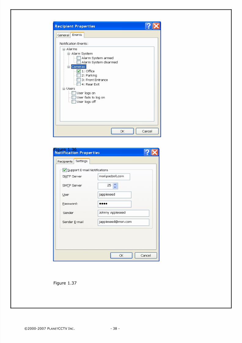
Figure 1.36
Figure 1.37
8/4/2019 PlanetCCTV Configuration Guide Ver 4
http://slidepdf.com/reader/full/planetcctv-configuration-guide-ver-4 39/72
©2000-2007 PLANETCCTV INC. - 39 -
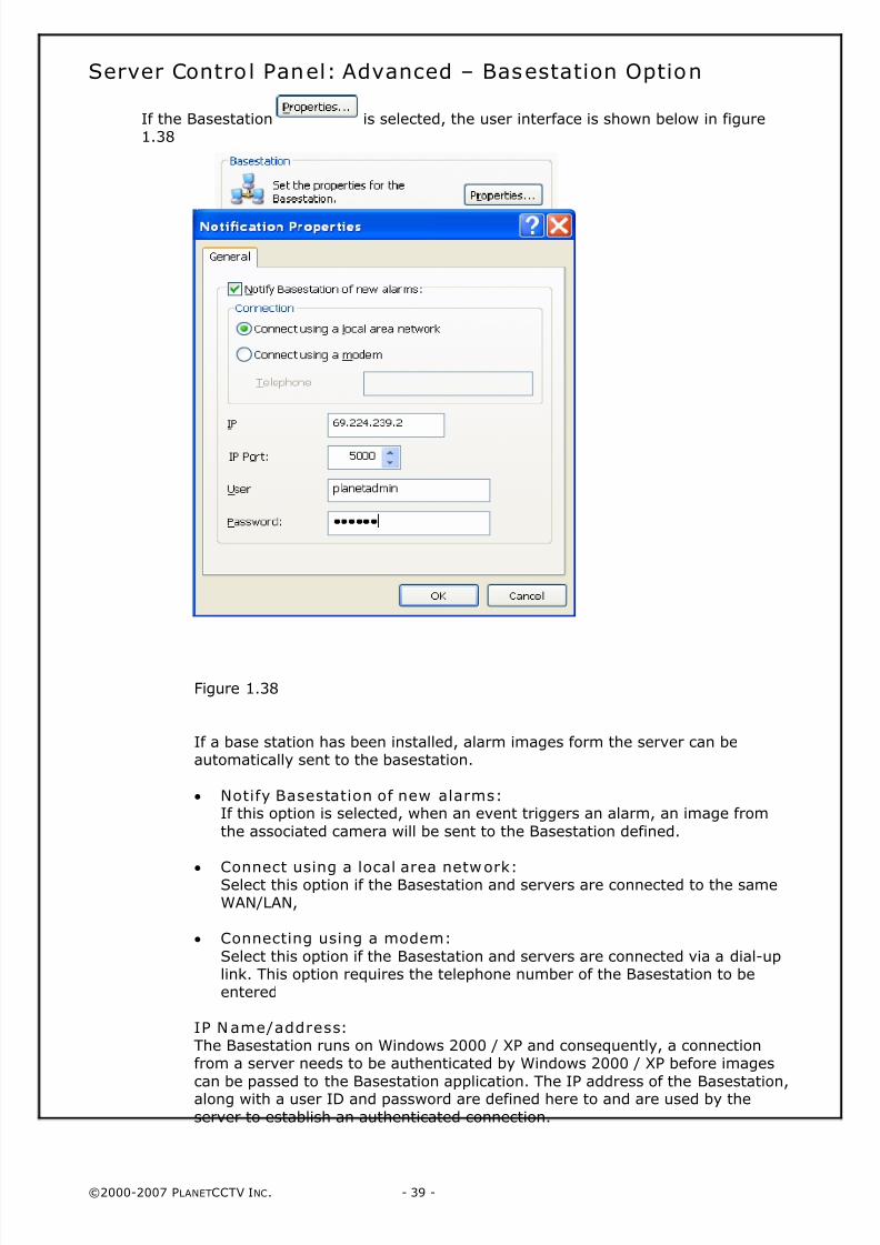
Server Control Panel: Advanced – Basestation Option
If the Basestation is selected, the user interface is shown below in figure1.38
Figure 1.38
If a base station has been installed, alarm images form the server can beautomatically sent to the basestation.
• Notify Basestation of new alarms:If this option is selected, when an event triggers an alarm, an image from
the associated camera will be sent to the Basestation defined.
•
Connect using a local area network:Select this option if the Basestation and servers are connected to the sameWAN/LAN,
• Connecting using a modem:
Select this option if the Basestation and servers are connected via a dial-uplink. This option requires the telephone number of the Basestation to beentered
IP Name/address: The Basestation runs on Windows 2000 / XP and consequently, a connectionfrom a server needs to be authenticated by Windows 2000 / XP before images
can be passed to the Basestation application. The IP address of the Basestation,along with a user ID and password are defined here to and are used by the
server to establish an authenticated connection.
8/4/2019 PlanetCCTV Configuration Guide Ver 4
http://slidepdf.com/reader/full/planetcctv-configuration-guide-ver-4 40/72
©2000-2007 PLANETCCTV INC. - 40 -
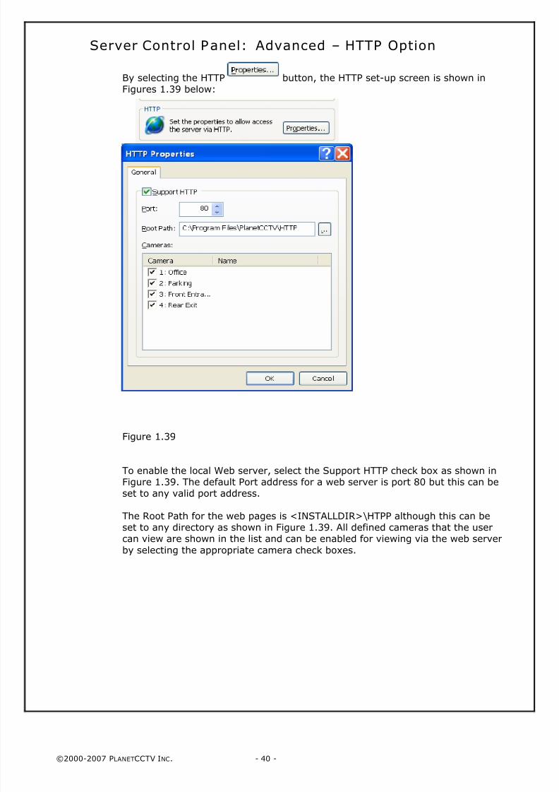
Server Control Panel: Advanced – HTTP Option
By selecting the HTTP button, the HTTP set-up screen is shown inFigures 1.39 below:
Figure 1.39
To enable the local Web server, select the Support HTTP check box as shown inFigure 1.39. The default Port address for a web server is port 80 but this can beset to any valid port address.
The Root Path for the web pages is <INSTALLDIR>\HTPP although this can beset to any directory as shown in Figure 1.39. All defined cameras that the usercan view are shown in the list and can be enabled for viewing via the web server
by selecting the appropriate camera check boxes.
8/4/2019 PlanetCCTV Configuration Guide Ver 4
http://slidepdf.com/reader/full/planetcctv-configuration-guide-ver-4 41/72
©2000-2007 PLANETCCTV INC. - 41 -
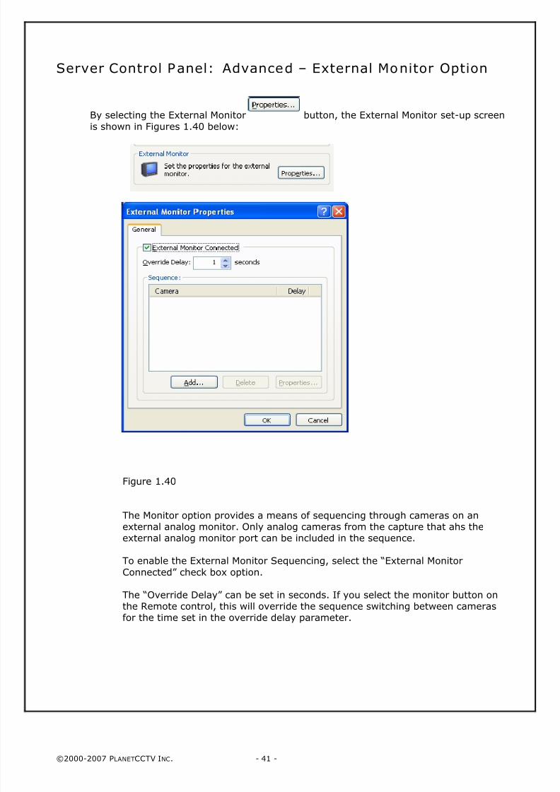
Server Control Panel: Advanced – External Monitor Option
By selecting the External Monitor button, the External Monitor set-up screen
is shown in Figures 1.40 below:
Figure 1.40
The Monitor option provides a means of sequencing through cameras on anexternal analog monitor. Only analog cameras from the capture that ahs theexternal analog monitor port can be included in the sequence.
To enable the External Monitor Sequencing, select the “External Monitor
Connected” check box option.
The “Override Delay” can be set in seconds. If you select the monitor button onthe Remote control, this will override the sequence switching between camerasfor the time set in the override delay parameter.
8/4/2019 PlanetCCTV Configuration Guide Ver 4
http://slidepdf.com/reader/full/planetcctv-configuration-guide-ver-4 42/72
©2000-2007 PLANETCCTV INC. - 42 -
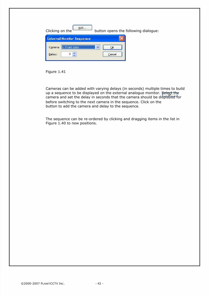
Clicking on the button opens the following dialogue:
Figure 1.41
Cameras can be added with varying delays (in seconds) multiple times to build
up a sequence to be displayed on the external analogue monitor. Select thecamera and set the delay in seconds that the camera should be displayed for
before switching to the next camera in the sequence. Click on thebutton to add the camera and delay to the sequence.
The sequence can be re-ordered by clicking and dragging items in the list inFigure 1.40 to new positions.
8/4/2019 PlanetCCTV Configuration Guide Ver 4
http://slidepdf.com/reader/full/planetcctv-configuration-guide-ver-4 43/72
©2000-2007 PLANETCCTV INC. - 43 -
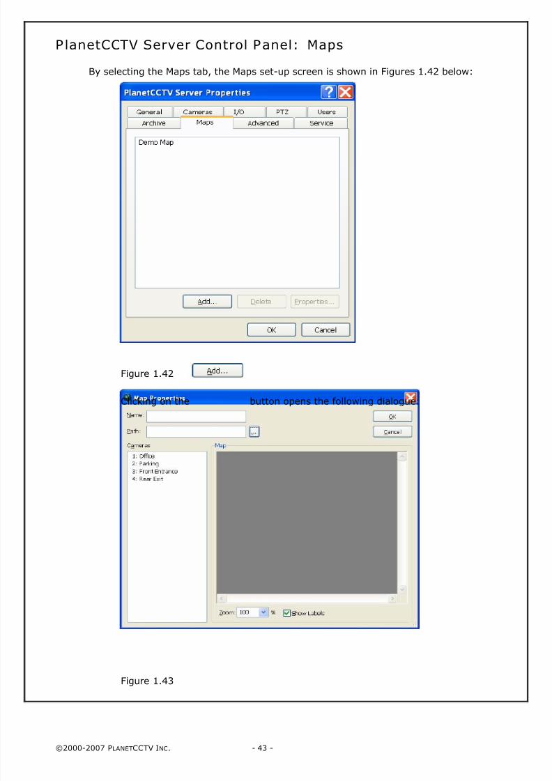
PlanetCCTV Server Control Panel: Maps
By selecting the Maps tab, the Maps set-up screen is shown in Figures 1.42 below:
Figure 1.42
Clicking on the button opens the following dialogue:
Figure 1.43
8/4/2019 PlanetCCTV Configuration Guide Ver 4
http://slidepdf.com/reader/full/planetcctv-configuration-guide-ver-4 44/72
©2000-2007 PLANETCCTV INC. - 44 -
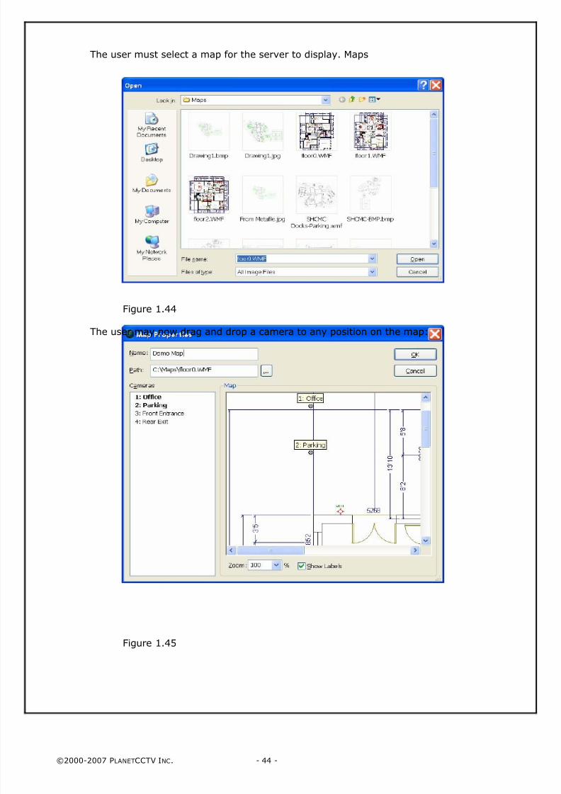
The user must select a map for the server to display. Maps
Figure 1.44
The user may now drag and drop a camera to any position on the map:
Figure 1.45
8/4/2019 PlanetCCTV Configuration Guide Ver 4
http://slidepdf.com/reader/full/planetcctv-configuration-guide-ver-4 45/72
©2000-2007 PLANETCCTV INC. - 45 -
PlanetCCTV Server Control Panel: Service
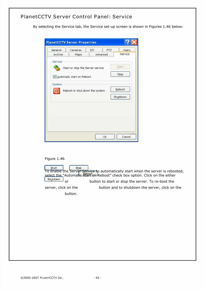
By selecting the Service tab, the Service set-up screen is shown in Figures 1.46 below:
Figure 1.46
To enable the Server Service to automatically start when the server is rebooted,
select the “Automatic start on Reboot” check box option. Click on the either
or button to start or stop the server. To re-boot the
server, click on the button and to shutdown the server, click on the
button.

8/4/2019 PlanetCCTV Configuration Guide Ver 4
http://slidepdf.com/reader/full/planetcctv-configuration-guide-ver-4 46/72
©2000-2007 PLANETCCTV INC. - 46 -
PAGE 46 INTENTIONALLY LEFT BLANK
8/4/2019 PlanetCCTV Configuration Guide Ver 4
http://slidepdf.com/reader/full/planetcctv-configuration-guide-ver-4 47/72
©2000-2007 PLANETCCTV INC. - 47 -
Chapter 2: Configuration of the PlanetCCTVBasestation Control Panel
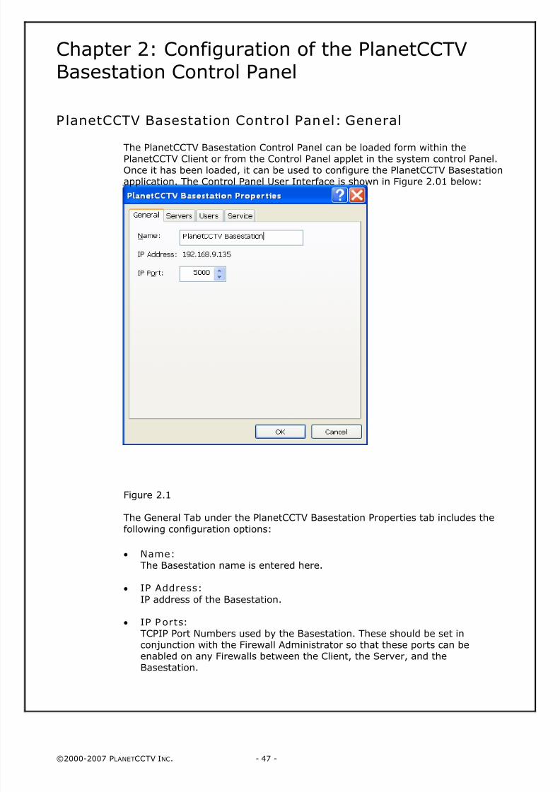
PlanetCCTV Basestation Control Panel: General
The PlanetCCTV Basestation Control Panel can be loaded form within thePlanetCCTV Client or from the Control Panel applet in the system control Panel.Once it has been loaded, it can be used to configure the PlanetCCTV Basestationapplication. The Control Panel User Interface is shown in Figure 2.01 below:
Figure 2.1
The General Tab under the PlanetCCTV Basestation Properties tab includes the
following configuration options:
• Name: The Basestation name is entered here.
• IP Address:
IP address of the Basestation.
• IP P orts:TCPIP Port Numbers used by the Basestation. These should be set inconjunction with the Firewall Administrator so that these ports can beenabled on any Firewalls between the Client, the Server, and theBasestation.
8/4/2019 PlanetCCTV Configuration Guide Ver 4
http://slidepdf.com/reader/full/planetcctv-configuration-guide-ver-4 48/72
©2000-2007 PLANETCCTV INC. - 48 -
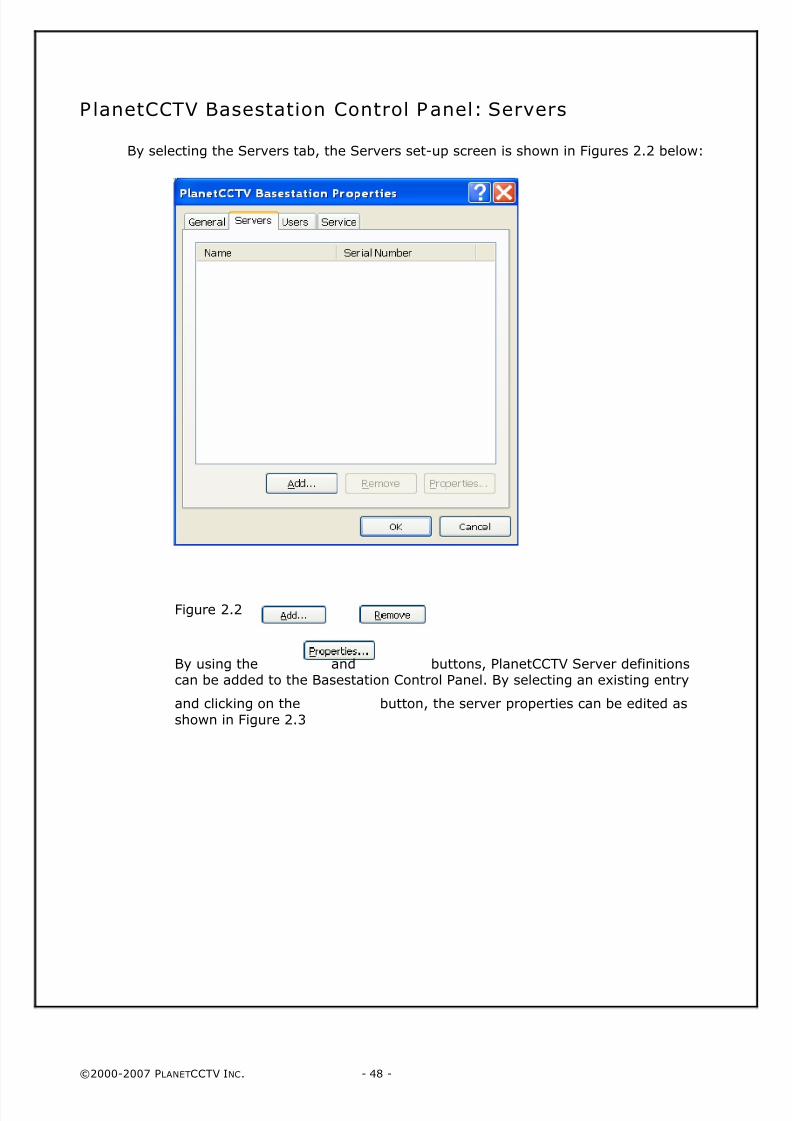
PlanetCCTV Basestation Control Panel: Servers
By selecting the Servers tab, the Servers set-up screen is shown in Figures 2.2 below:
Figure 2.2
By using the and buttons, PlanetCCTV Server definitionscan be added to the Basestation Control Panel. By selecting an existing entry
and clicking on the button, the server properties can be edited as
shown in Figure 2.3
8/4/2019 PlanetCCTV Configuration Guide Ver 4
http://slidepdf.com/reader/full/planetcctv-configuration-guide-ver-4 49/72
©2000-2007 PLANETCCTV INC. - 49 -
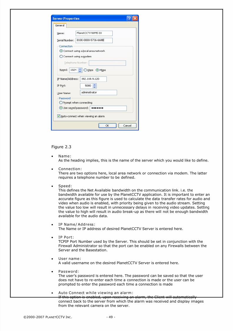
Figure 2.3
• Name:As the heading implies, this is the name of the server which you would like to define.
• Connection:
There are two options here, local area network or connection via modem. The latterrequires a telephone number to be defined.
• Speed:This defines the Net Available bandwidth on the communication link. i.e. thebandwidth available for use by the PlanetCCTV application. It is important to enter anaccurate figure as this figure is used to calculate the data transfer rates for audio andvideo when audio is enabled, with priority being given to the audio stream. Settingthe value too low will result in unnecessary delays in receiving video updates. Settingthe value to high will result in audio break-up as there will not be enough bandwidthavailable for the audio data.
• IP Name/ Address:
The Name or IP address of desired PlanetCCTV Server is entered here.
• IP Port:TCPIP Port Number used by the Server. This should be set in conjunction with theFirewall Administrator so that the port can be enabled on any Firewalls between theServer and the Basestation.
• User name:A valid username on the desired PlanetCCTV Server is entered here.
• Password: The user’s password is entered here. The password can be saved so that the userdoes not have to re-enter each time a connection is made or the user can beprompted to enter the password each time a connection is made
• Auto Connect while viewing an alarm:If this option is enabled, upon receiving an alarm, the Client will automaticallyconnect back to the server from which the alarm was received and display imagesfrom the relevant camera on the server.
8/4/2019 PlanetCCTV Configuration Guide Ver 4
http://slidepdf.com/reader/full/planetcctv-configuration-guide-ver-4 50/72
©2000-2007 PLANETCCTV INC. - 50 -
PlanetCCTV Basestation Control P anel: Users
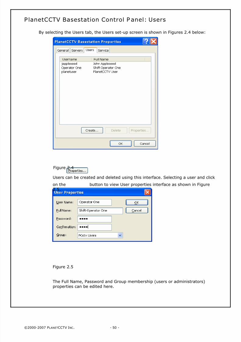
By selecting the Users tab, the Users set-up screen is shown in Figures 2.4 below:
Figure 2.4
Users can be created and deleted using this interface. Selecting a user and click
on the button to view User properties interface as shown in Figure2.5.
Figure 2.5
The Full Name, Password and Group membership (users or administrators)properties can be edited here.
8/4/2019 PlanetCCTV Configuration Guide Ver 4
http://slidepdf.com/reader/full/planetcctv-configuration-guide-ver-4 51/72
©2000-2007 PLANETCCTV INC. - 51 -
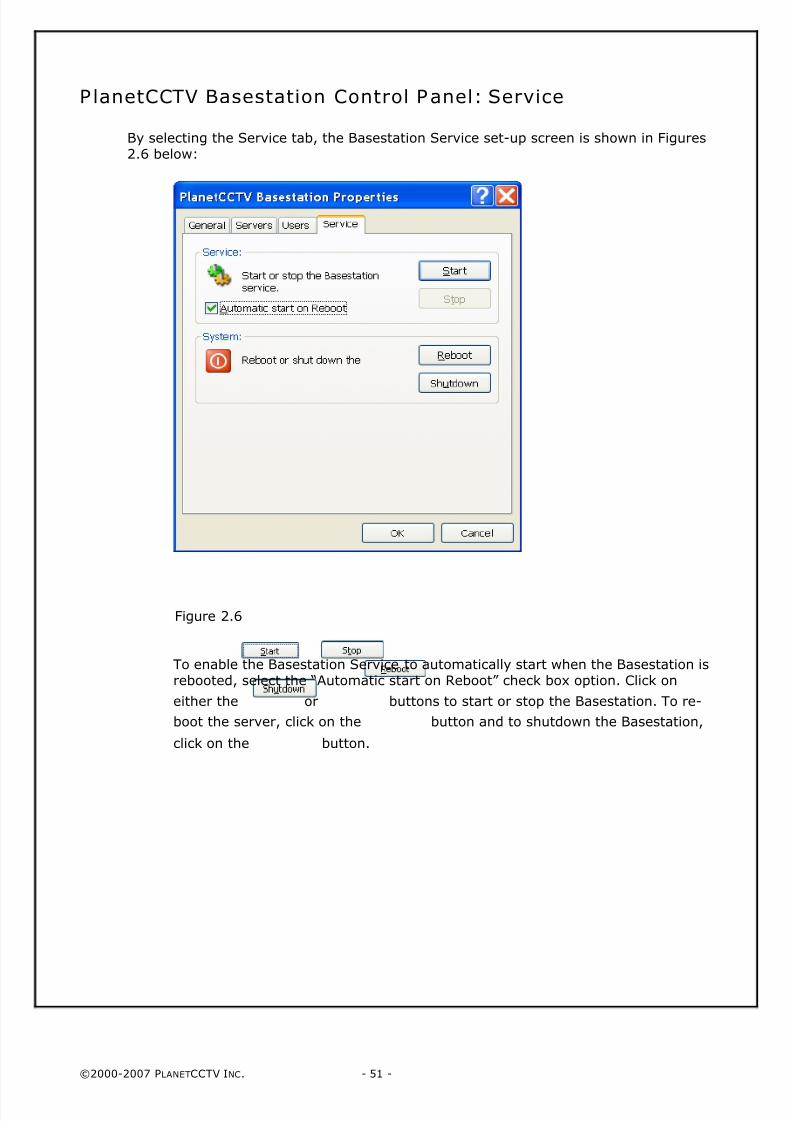
PlanetCCTV Basestation Control Panel: Service
By selecting the Service tab, the Basestation Service set-up screen is shown in Figures2.6 below:
Figure 2.6
To enable the Basestation Service to automatically start when the Basestation isrebooted, select the “Automatic start on Reboot” check box option. Click on
either the or buttons to start or stop the Basestation. To re-
boot the server, click on the button and to shutdown the Basestation,
click on the button.

8/4/2019 PlanetCCTV Configuration Guide Ver 4
http://slidepdf.com/reader/full/planetcctv-configuration-guide-ver-4 52/72
©2000-2007 PLANETCCTV INC. - 52 -
P AGE 5 2 LEFT I NTENTI ONALLY B LANK
8/4/2019 PlanetCCTV Configuration Guide Ver 4
http://slidepdf.com/reader/full/planetcctv-configuration-guide-ver-4 53/72
©2000-2007 PLANETCCTV INC. - 53 -
Chapter 3: Configuration of the PlanetCCTVServer Service
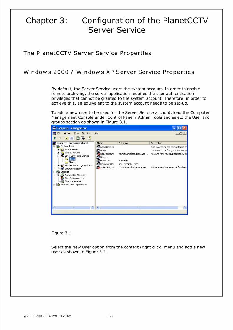
The P lanetCCTV Server Service Properties
Window s 2000 / Window s XP Server Service Properties
By default, the Server Service users the system account. In order to enableremote archiving, the server application requires the user authenticationprivileges that cannot be granted to the system account. Therefore, in order to
achieve this, an equivalent to the system account needs to be set-up.
To add a new user to be used for the Server Service account, load the ComputerManagement Console under Control Panel / Admin Tools and select the User andgroups section as shown in Figure 3.1.
Figure 3.1
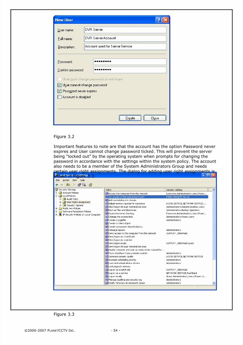
Select the New User option from the context (right click) menu and add a newuser as shown in Figure 3.2.
8/4/2019 PlanetCCTV Configuration Guide Ver 4
http://slidepdf.com/reader/full/planetcctv-configuration-guide-ver-4 54/72
©2000-2007 PLANETCCTV INC. - 54 -
Figure 3.2
Important features to note are that the account has the option Password neverexpires and User cannot change password ticked. This will prevent the serverbeing “locked out” by the operating system when prompts for changing thepassword in accordance with the settings within the system policy. The accountalso needs to be a member of the System Administrators Group and needs
certain user right assignments. The dialog for adding user right assignments isshown in Figure 3.3.
Figure 3.3
8/4/2019 PlanetCCTV Configuration Guide Ver 4
http://slidepdf.com/reader/full/planetcctv-configuration-guide-ver-4 55/72
©2000-2007 PLANETCCTV INC. - 55 -
These are added by selecting the appropriate rights in turn and adding the
appropriate user account to the user right assignment. For a user account to beused to run as a service, the following rights are needed.
• Act as part of the operating system
• Log on as a service
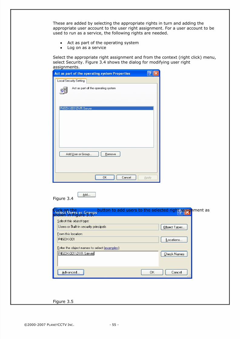
Select the appropriate right assignment and from the context (right click) menu,select Security. Figure 3.4 shows the dialog for modifying user rightassignments.
Figure 3.4
Click on the button to add users to the selected right assignment asshown in Figure 3.5.
Figure 3.5
8/4/2019 PlanetCCTV Configuration Guide Ver 4
http://slidepdf.com/reader/full/planetcctv-configuration-guide-ver-4 56/72
©2000-2007 PLANETCCTV INC. - 56 -
Once the user has been added to the right assignment, click on thebutton to commit the changes. Repeat for the remaining user right assignments.
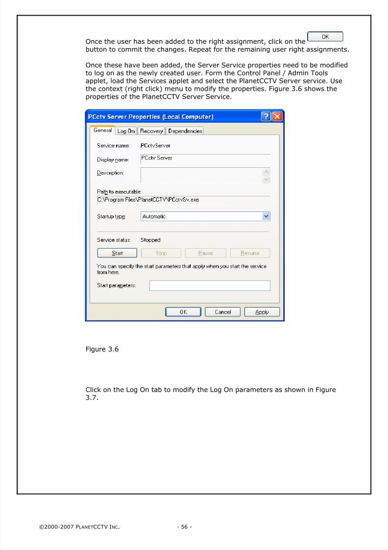
Once these have been added, the Server Service properties need to be modifiedto log on as the newly created user. Form the Control Panel / Admin Toolsapplet, load the Services applet and select the PlanetCCTV Server service. Usethe context (right click) menu to modify the properties. Figure 3.6 shows the
properties of the PlanetCCTV Server Service.
Figure 3.6
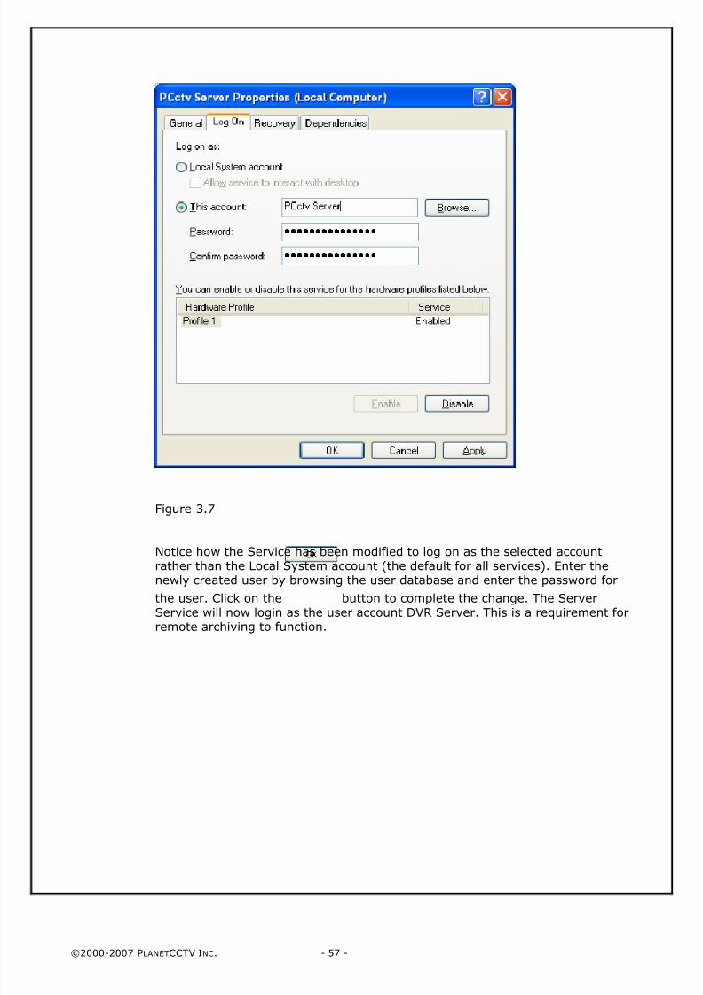
Click on the Log On tab to modify the Log On parameters as shown in Figure3.7.
8/4/2019 PlanetCCTV Configuration Guide Ver 4
http://slidepdf.com/reader/full/planetcctv-configuration-guide-ver-4 57/72
©2000-2007 PLANETCCTV INC. - 57 -
Figure 3.7
Notice how the Service has been modified to log on as the selected accountrather than the Local System account (the default for all services). Enter thenewly created user by browsing the user database and enter the password for
the user. Click on the button to complete the change. The ServerService will now login as the user account DVR Server. This is a requirement forremote archiving to function.

8/4/2019 PlanetCCTV Configuration Guide Ver 4
http://slidepdf.com/reader/full/planetcctv-configuration-guide-ver-4 58/72
©2000-2007 PLANETCCTV INC. - 58 -
PAGE 58 LEFT INTENTIONALLY BLANK
8/4/2019 PlanetCCTV Configuration Guide Ver 4
http://slidepdf.com/reader/full/planetcctv-configuration-guide-ver-4 59/72
©2000-2007 PLANETCCTV INC. - 59 -
Chapter 4: Configuration of the RemoteAccess Server
The PlanetCCTV Remote Access Server
Window s 2000 / Windows XP Remote Access Server
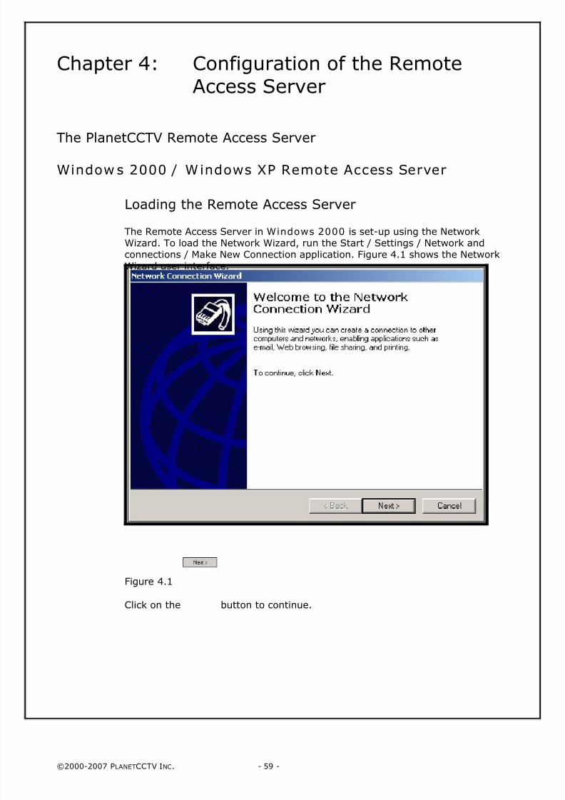
Loading the Remote Access Server
The Remote Access Server in Windows 2000 is set-up using the NetworkWizard. To load the Network Wizard, run the Start / Settings / Network andconnections / Make New Connection application. Figure 4.1 shows the NetworkWizard user interface.
Figure 4.1
Click on the button to continue.
8/4/2019 PlanetCCTV Configuration Guide Ver 4
http://slidepdf.com/reader/full/planetcctv-configuration-guide-ver-4 60/72
©2000-2007 PLANETCCTV INC. - 60 -
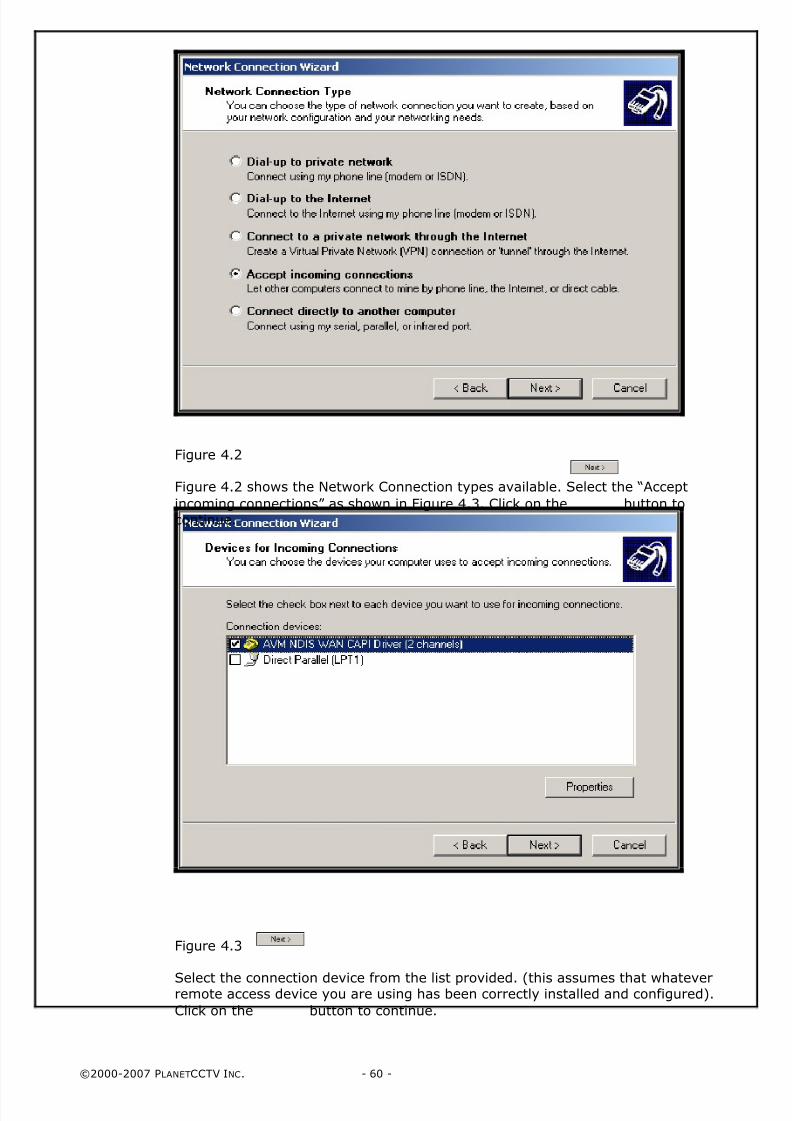
Figure 4.2
Figure 4.2 shows the Network Connection types available. Select the “Accept
incoming connections” as shown in Figure 4.3. Click on the button tocontinue.
Figure 4.3
Select the connection device from the list provided. (this assumes that whateverremote access device you are using has been correctly installed and configured).
Click on the button to continue.
8/4/2019 PlanetCCTV Configuration Guide Ver 4
http://slidepdf.com/reader/full/planetcctv-configuration-guide-ver-4 61/72
©2000-2007 PLANETCCTV INC. - 61 -
Figure 4.4
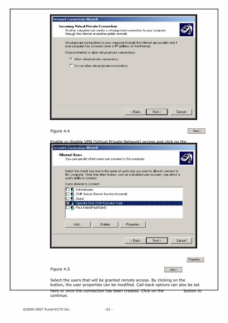
Enable or disable VPN (Virtual Private Network) access and click on the
button to continue.
Figure 4.5
Select the users that will be granted remote access. By clicking on thebutton, the user properties can be modified. Call-back options can also be set
here or once the connection has been created. Click on the button tocontinue.
8/4/2019 PlanetCCTV Configuration Guide Ver 4
http://slidepdf.com/reader/full/planetcctv-configuration-guide-ver-4 62/72
©2000-2007 PLANETCCTV INC. - 62 -
Figure 4.6
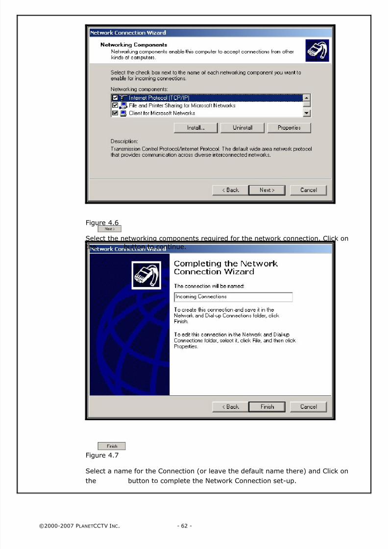
Select the networking components required for the network connection. Click on
the button to continue.
Figure 4.7
Select a name for the Connection (or leave the default name there) and Click on
the button to complete the Network Connection set-up.
8/4/2019 PlanetCCTV Configuration Guide Ver 4
http://slidepdf.com/reader/full/planetcctv-configuration-guide-ver-4 63/72
©2000-2007 PLANETCCTV INC. - 63 -
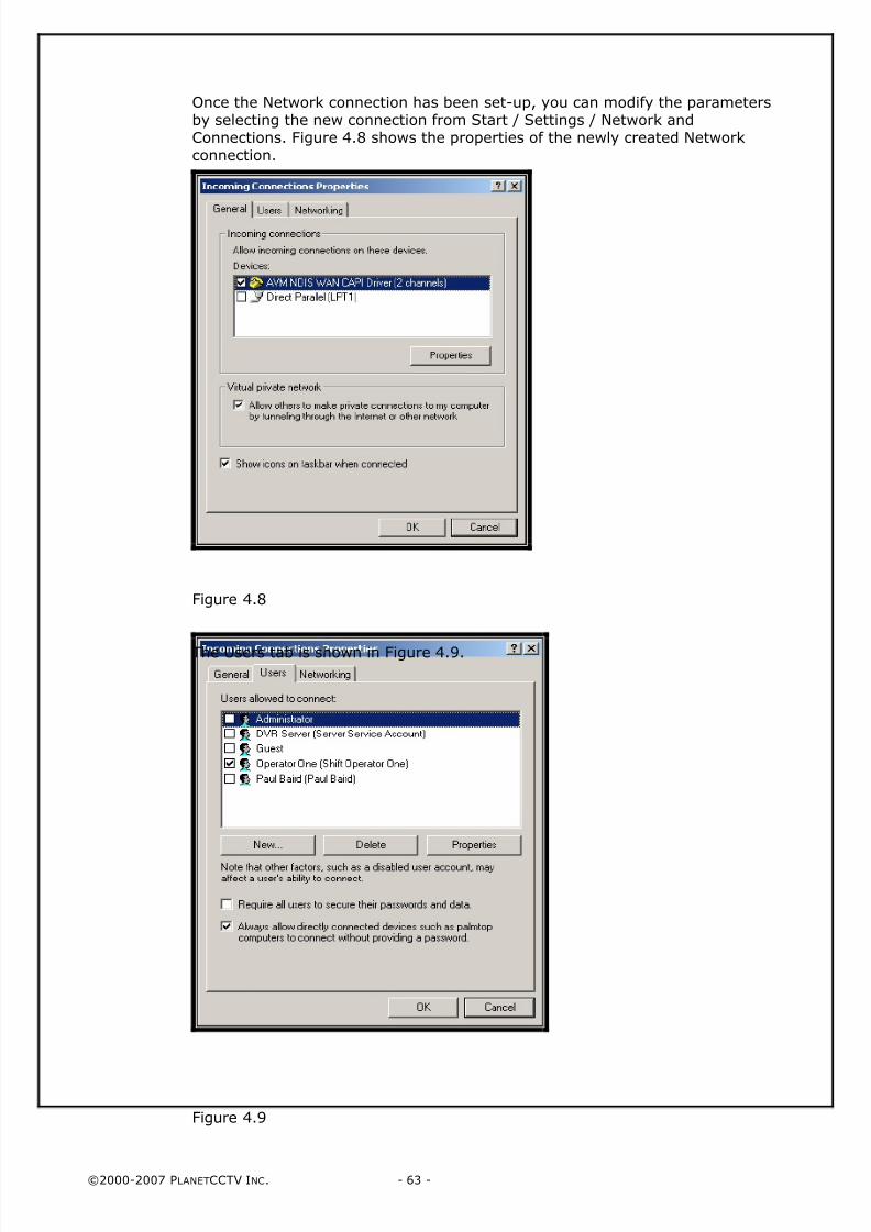
Once the Network connection has been set-up, you can modify the parametersby selecting the new connection from Start / Settings / Network andConnections. Figure 4.8 shows the properties of the newly created Networkconnection.
Figure 4.8
The Users tab is shown in Figure 4.9.
Figure 4.9
8/4/2019 PlanetCCTV Configuration Guide Ver 4
http://slidepdf.com/reader/full/planetcctv-configuration-guide-ver-4 64/72
©2000-2007 PLANETCCTV INC. - 64 -
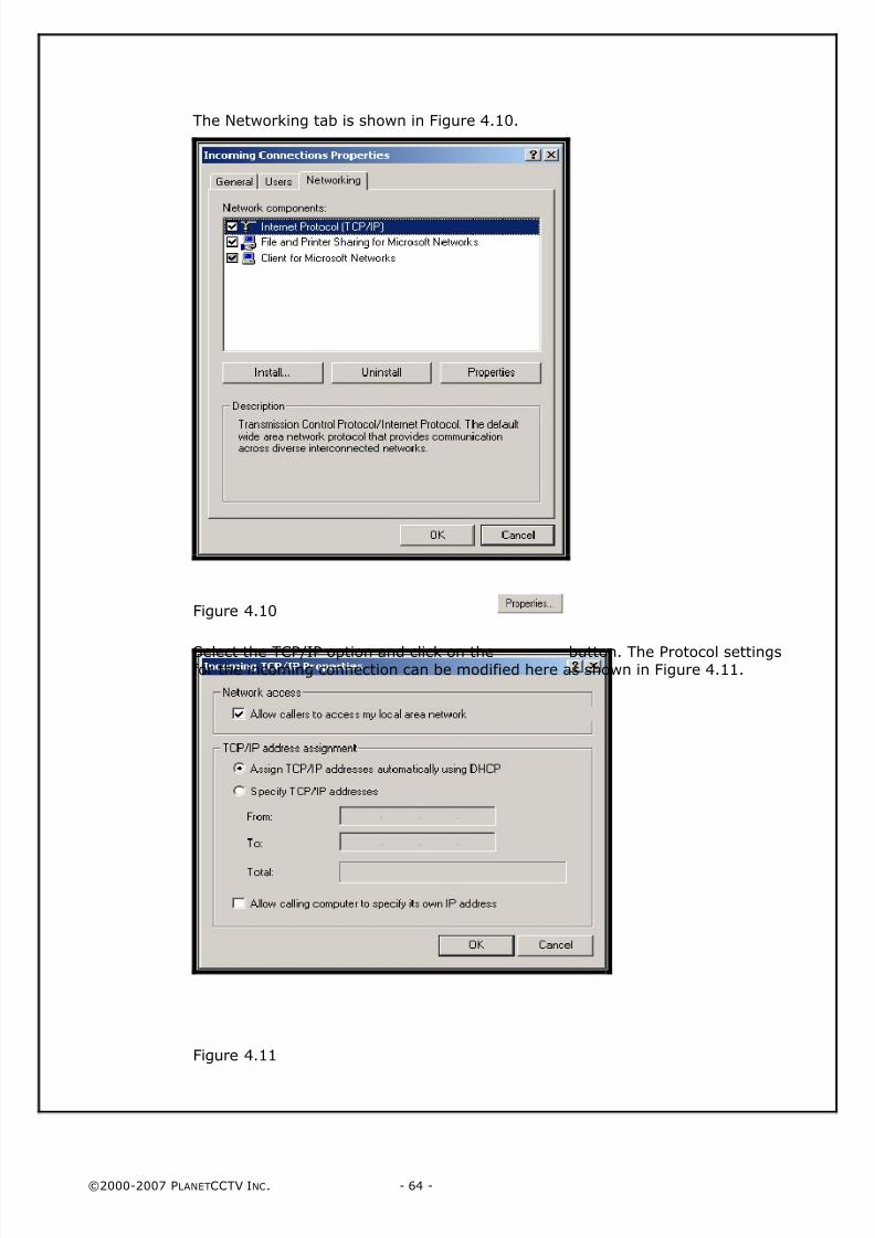
The Networking tab is shown in Figure 4.10.
Figure 4.10
Select the TCP/IP option and click on the button. The Protocol settingsfor the incoming connection can be modified here as shown in Figure 4.11.
Figure 4.11
8/4/2019 PlanetCCTV Configuration Guide Ver 4
http://slidepdf.com/reader/full/planetcctv-configuration-guide-ver-4 65/72
©2000-2007 PLANETCCTV INC. - 65 -
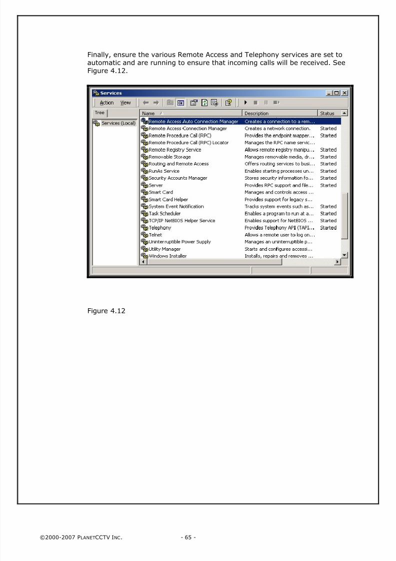
Finally, ensure the various Remote Access and Telephony services are set toautomatic and are running to ensure that incoming calls will be received. SeeFigure 4.12.
Figure 4.12

8/4/2019 PlanetCCTV Configuration Guide Ver 4
http://slidepdf.com/reader/full/planetcctv-configuration-guide-ver-4 66/72
©2000-2007 PLANETCCTV INC. - 66 -
PAGE 66 LEFT INTENTIONALLY BLANK
8/4/2019 PlanetCCTV Configuration Guide Ver 4
http://slidepdf.com/reader/full/planetcctv-configuration-guide-ver-4 67/72
©2000-2007 PLANETCCTV INC. - 67 -
Appendices
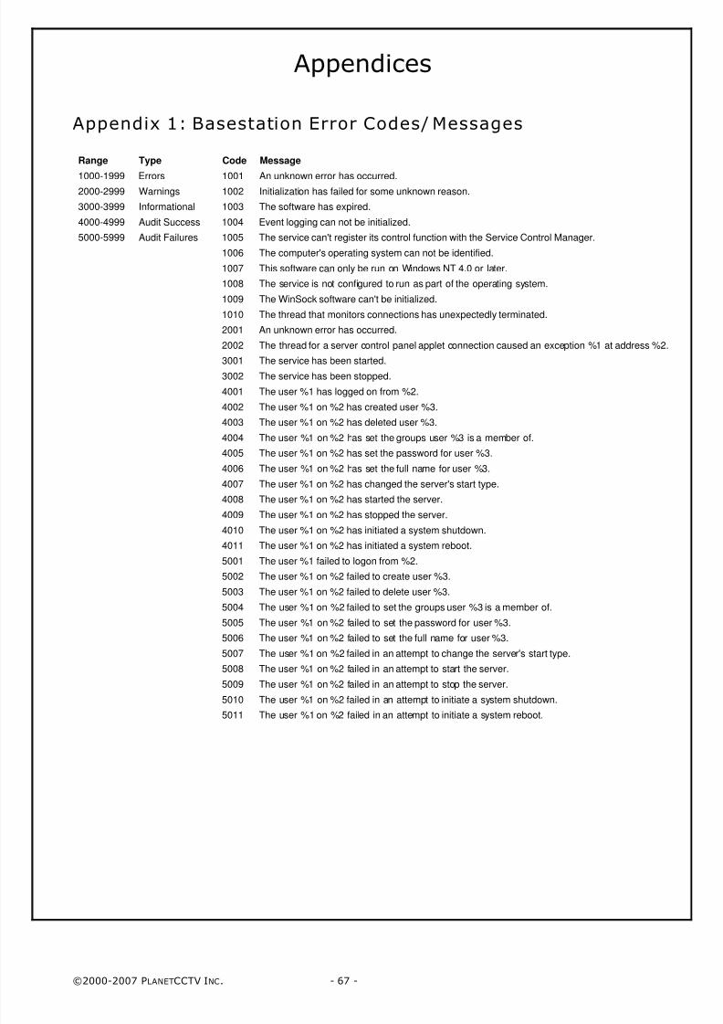
Appendix 1: Basestation Error Codes/ Messages
Range Type Code Message
1000-1999 Errors 1001 An unknown error has occurred.2000-2999 Warnings 1002 Initialization has failed for some unknown reason.
3000-3999 Informational 1003 The software has expired.
4000-4999 Audit Success 1004 Event logging can not be initialized.
5000-5999 Audit Failures 1005 The service can't register its control function with the Service Control Manager.
1006 The computer's operating system can not be identified.
1007 This software can only be run on Windows NT 4.0 or later.
1008 The service is not configured to run as part of the operating system.
1009 The WinSock software can't be initialized.
1010 The thread that monitors connections has unexpectedly terminated.
2001 An unknown error has occurred.
2002 The thread for a server control panel applet connection caused an exception %1 at address %2.
3001 The service has been started.
3002 The service has been stopped.
4001 The user %1 has logged on from %2.
4002 The user %1 on %2 has created user %3.
4003 The user %1 on %2 has deleted user %3.
4004 The user %1 on %2 has set the groups user %3 is a member of.
4005 The user %1 on %2 has set the password for user %3.
4006 The user %1 on %2 has set the full name for user %3.
4007 The user %1 on %2 has changed the server's start type.
4008 The user %1 on %2 has started the server.
4009 The user %1 on %2 has stopped the server.
4010 The user %1 on %2 has initiated a system shutdown.
4011 The user %1 on %2 has initiated a system reboot.
5001 The user %1 failed to logon from %2.
5002 The user %1 on %2 failed to create user %3.
5003 The user %1 on %2 failed to delete user %3.
5004 The user %1 on %2 failed to set the groups user %3 is a member of.
5005 The user %1 on %2 failed to set the password for user %3.
5006 The user %1 on %2 failed to set the full name for user %3.
5007 The user %1 on %2 failed in an attempt to change the server's start type.
5008 The user %1 on %2 failed in an attempt to start the server.
5009 The user %1 on %2 failed in an attempt to stop the server.
5010 The user %1 on %2 failed in an attempt to initiate a system shutdown.
5011 The user %1 on %2 failed in an attempt to initiate a system reboot.
8/4/2019 PlanetCCTV Configuration Guide Ver 4
http://slidepdf.com/reader/full/planetcctv-configuration-guide-ver-4 68/72
©2000-2007 PLANETCCTV INC. - 68 -
Appendix 1: Server Error Codes/ Messages
Range Type Code Message
1000-1999 Errors 1001 An unknown error has occurred.
2000-2999 Warnings 1002 Initialization has failed for some unknown reason.
3000-3999 Informationals 1003 The software has expired.
4000-4999AuditSuccess
1004 Event logging can't be initialized.
5000-5999 Audit Failures 1005 The service can't register its control function with the Service Control Manager.
1006 The computer's operating system can't be identified.1007 This software can only be run on Windows 2000 or later.
1008 The camera properties can't be obtained from the registry.
1009 No camera is set up to capture frames.
1010 The frame files can't be opened.
1011 The alarm file can't be opened.
1012 The WinSock software can't be initialized.
1013 Video capture can't be initialized.
1014 A video compression codec can't be initialized.
1015 Information for the clients can't be initialized.
1016 A thread can't be created to capture frames.
1017 Flags can't be written to the frame file %1.
1018 Frame information can't be written to frame file %1.
1019 The thread that captures frames has unexpectedly terminated.
1020 The thread that compresses frames has unexpectedly terminated.1021 The thread that monitors connections has unexpectedly terminated.
1022 The server's properties can't be obtained from the registry.
1023 The server's basestation properties can't be obtained from the registry.
1024 The server's I/O properties can't be obtained from the registry.
1025 The server's archive properties can't be obtained from the registry.
1026 The configured archive drive doesn't exist.
1027 The configured drive type is invalid for the archive drive.
1028 The archive drive's type is unsupported.
1029 There are too few frame files to safely archive.
1030 Archiving can't be initialized.
1031 The recording of alarms can't be initialized.
1032 The I/O card can't be initialized.
1033 There is no license.
1034 The license is corrupted.
1035 The trial license has expired.
1036 The computer's time zone is not standard and can't be used.
1037 The audio software can't be initialized.
1038 Archiving can't be initialized because the service doesn't have access to the network.
1039 The server is not configured to run as part of the operating system.
1040 Not enough memory can be allocated to run the server.
1041 Domain information for the computer can't be obtained.
1042 The PTZ software can't be initialized.
1043 A thread caused an exception %1 at address %2.
1044 The frame rate is invalid.
1045 Data can't be read from the frame file %1.
1046 Data can't be written to the frame file %1.
1047 The system time has moved backwards more than is permitted.
1048 The thread that writes frames has unexpectedly terminated.
1049 The service has failed to restart itself.
1050 The watchdog can't be initialized.
1051 The server's map properties can't be obtained from the registry.
2001 An unknown error has occurred.
2002 The video compression codec can't compress a frame.
2003 The PTZ properties can't be obtained or are invalid. All PTZ functionality has been disabled.
2004 The PTZ properties for camera %1 are invalid. PTZ functionality has been disabled for camera %1.
2006 The thread for a client connection caused an exception %1 at address %2.
2007 The thread for a monitor connection caused an exception %1 at address %2.
2008 The PTZ software can't be initialized. All PTZ functionality has been disabled.
2009 The HTTP properties can't be obtained or are invalid. All HTTP functionality has been disabled.
2010 The HTTP software can't be initialized. All HTTP functionality has been disabled.
2011 The HTTP root path specified is invalid or doesn't exist. All HTTP functionality has been disabled.
2012 The HTTP port specified is invalid or already in use. All HTTP functionality has been disabled.
2013 The Video Out software can't be initialized. All Video Out functionality has been disabled.
2014 The system page size is larger than expected.
2015 The archiving of one of the frame files has failed.
2016 There is no media in the archive drive.
2017 The media in the archive drive is full.
8/4/2019 PlanetCCTV Configuration Guide Ver 4
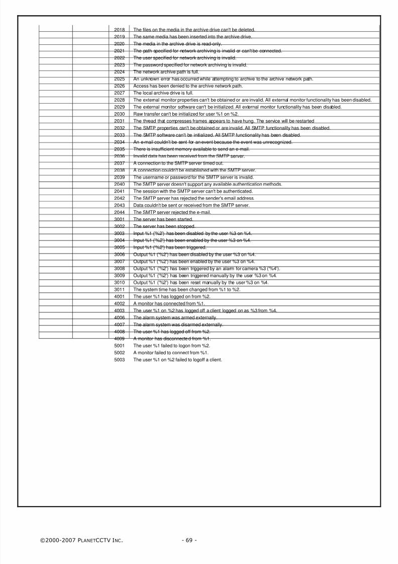
http://slidepdf.com/reader/full/planetcctv-configuration-guide-ver-4 69/72
©2000-2007 PLANETCCTV INC. - 69 -
2018 The files on the media in the archive drive can't be deleted.
2019 The same media has been inserted into the archive drive.
2020 The media in the archive drive is read-only.
2021 The path specified for network archiving is invalid or can't be connected.
2022 The user specified for network archiving is invalid.
2023 The password specified for network archiving is invalid.
2024 The network archive path is full.
2025 An unknown error has occurred while attempting to archive to the archive network path.
2026 Access has been denied to the archive network path.
2027 The local archive drive is full.
2028 The external monitor properties can't be obtained or are invalid. All external monitor functionality has been disabled.
2029 The external monitor software can't be initialized. All external monitor functionality has been disabled.
2030 Raw transfer can't be initialized for user %1 on %2.
2031 The thread that compresses frames appears to have hung. The service will be restarted
2032 The SMTP properties can't be obtained or are invalid. All SMTP functionality has been disabled.
2033 The SMTP software can't be initialized. All SMTP functionality has been disabled.
2034 An e-mail couldn't be sent for an event because the event was unrecognized.
2035 There is insufficient memory available to send an e-mail.
2036 Invalid data has been received from the SMTP server.
2037 A connection to the SMTP server timed out.
2038 A connection couldn't be established with the SMTP server.
2039 The username or password for the SMTP server is invalid.
2040 The SMTP server doesn't support any available authentication methods.
2041 The session with the SMTP server can't be authenticated.
2042 The SMTP server has rejected the sender's email address.
2043 Data couldn't be sent or received from the SMTP server.
2044 The SMTP server rejected the e-mail.
3001 The server has been started.
3002 The server has been stopped.
3003 Input %1 ('%2') has been disabled by the user %3 on %4.
3004 Input %1 ('%2') has been enabled by the user %3 on %4.
3005 Input %1 ('%2') has been triggered.
3006 Output %1 ('%2') has been disabled by the user %3 on %4.
3007 Output %1 ('%2') has been enabled by the user %3 on %4.
3008 Output %1 ('%2') has been triggered by an alarm for camera %3 ('%4').
3009 Output %1 ('%2') has been triggered manually by the user %3 on %4.
3010 Output %1 ('%2') has been reset manually by the user %3 on %4.
3011 The system time has been changed from %1 to %2.
4001 The user %1 has logged on from %2.4002 A monitor has connected from %1.
4003 The user %1 on %2 has logged off a client logged on as %3 from %4.
4006 The alarm system was armed externally.
4007 The alarm system was disarmed externally.
4008 The user %1 has logged off from %2.
4009 A monitor has disconnected from %1.
5001 The user %1 failed to logon from %2.
5002 A monitor failed to connect from %1.
5003 The user %1 on %2 failed to logoff a client.
8/4/2019 PlanetCCTV Configuration Guide Ver 4
http://slidepdf.com/reader/full/planetcctv-configuration-guide-ver-4 70/72
©2000-2007 PLANETCCTV INC. - 70 -
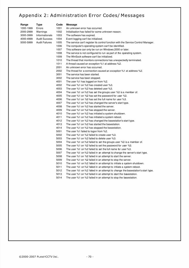
Appendix 2: Administration Error Codes/ Messages
Range Type Code Message
1000-1999 Errors 1001 An unknown error has occurred.
2000-2999 Warnings 1002 Initialisation has failed for some unknown reason.
3000-3999 Informationals 1003 The software has expired.
4000-4999 Audit Success 1004 Event logging can't be initialized.
5000-5999 Audit Failures 1005 The service can't register its control function with the Service Control Manager.
1006 The computer's operating system can't be identified.1007 This software can only be run on Windows 2000 or later.
1008 The service is not configured to run as part of the operating system.
1009 The WinSock software can't be initialized.
1010 The thread that monitors connections has unexpectedly terminated.
1011 A thread caused an exception %1 at address %2.
2001 An unknown error has occurred.
2002 The thread for a connection caused an exception %1 at address %2.
3001 The service has been started.
3002 The service has been stopped.
4001 The user %1 has logged on from %2.
4002 The user %1 on %2 has created user %3.
4003 The user %1 on %2 has deleted user %3.
4004 The user %1 on %2 has set the groups user %3 is a member of.
4005 The user %1 on %2 has set the password for user %3.
4006 The user %1 on %2 has set the full name for user %3.
4007 The user %1 on %2 has changed the server's start type.
4008 The user %1 on %2 has started the server.
4009 The user %1 on %2 has stopped the server.
4010 The user %1 on %2 has initiated a system shutdown.
4011 The user %1 on %2 has initiated a system reboot.
4012 The user %1 on %2 has changed the basestation's start type.
4013 The user %1 on %2 has started the basestation.
4014 The user %1 on %2 has stopped the basestation.
5001 The user %1 failed to logon from %2.
5002 The user %1 on %2 failed to create user %3.
5003 The user %1 on %2 failed to delete user %3.
5004 The user %1 on %2 failed to set the groups user %3 is a member of.
5005 The user %1 on %2 failed to set the password for user %3.
5006 The user %1 on %2 failed to set the full name for user %3.
5007 The user %1 on %2 failed in an attempt to change the server's start type.
5008 The user %1 on %2 failed in an attempt to start the server.
5009 The user %1 on %2 failed in an attempt to stop the server.
5010 The user %1 on %2 failed in an attempt to initiate a system shutdown.
5011 The user %1 on %2 failed in an attempt to initiate a system reboot.
5012 The user %1 on %2 failed in an attempt to change the basestation's start type.
5013 The user %1 on %2 failed in an attempt to start the basestation.
5014 The user %1 on %2 failed in an attempt to stop the basestation.
8/4/2019 PlanetCCTV Configuration Guide Ver 4
http://slidepdf.com/reader/full/planetcctv-configuration-guide-ver-4 71/72
©2000-2007 PLANETCCTV INC. - 71 -
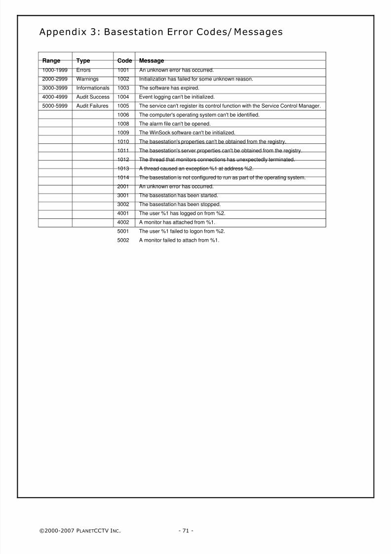
Appendix 3: Basestation Error Codes/ Messages
Range Type Code Message
1000-1999 Errors 1001 An unknown error has occurred.
2000-2999 Warnings 1002 Initialization has failed for some unknown reason.
3000-3999 Informationals 1003 The software has expired.
4000-4999 Audit Success 1004 Event logging can't be initialized.
5000-5999 Audit Failures 1005 The service can't register its control function with the Service Control Manager.
1006 The computer's operating system can't be identified.
1008 The alarm file can't be opened.
1009 The WinSock software can't be initialized.
1010 The basestation's properties can't be obtained from the registry.
1011 The basestation's server properties can't be obtained from the registry.
1012 The thread that monitors connections has unexpectedly terminated.
1013 A thread caused an exception %1 at address %2.
1014 The basestation is not configured to run as part of the operating system.
2001 An unknown error has occurred.
3001 The basestation has been started.
3002 The basestation has been stopped.
4001 The user %1 has logged on from %2.
4002 A monitor has attached from %1.
5001 The user %1 failed to logon from %2.
5002 A monitor failed to attach from %1.

8/4/2019 PlanetCCTV Configuration Guide Ver 4
http://slidepdf.com/reader/full/planetcctv-configuration-guide-ver-4 72/72
PlanetCCTV ® Digital Video Systems11440 West Bernardo Court
Suite 300San Diego, CA 92127
(858) 613-5200Fax : (858) 613-5201
Support : [email protected]
Sales : [email protected] Website : http://www.planetcctv.com
Dealer:


![[오픈소스컨설팅]Zabbix Installation and Configuration Guide](https://img.pdfslide.tips/doc/110x75/54b5064e4a79598a568b4630/zabbix-installation-and-configuration-guide.jpg)