Embed Size (px)
Citation preview
��Installation, Wiring,and Specifications
������������ �������
������������������
���������������������
����������������������
�������������� �����������������
���!"����#$������"����%� ��������������
���&'�%� ������ ������
���&'��������%� ���������(���(�����
������� �������(���(������� �
Inst
alla
tion,
Wiri
ng,
and
Spe
cific
atio
nsIn
stal
latio
n an
dS
afet
y G
uide
lines
2–2Installation, Wiring, and Specifications
Safety Guidelines
WARNING: Providing a safe operating environment for personnel and equipment isyour responsibility and should be your primary goal during system planning andinstallation. Automation systems can fail and may result in situations that can causeserious injury to personnel or damage to equipment. Do not rely on the automationsystem alone to provide a safe operating environment. You should use externalelectromechanical devices, such as relays or limit switches, that are independent ofthe PLC system to provide protection for any part of the system that may causepersonal injury or damage.
Every automation application is different, so there may be special requirements foryour particular application. Make sure you follow all National, State, and localgovernment requirements for the proper installation and use of your equipment.
The best way to provide a safe operating environment is to make personnel andequipment safety part of the planning process. You should examine every aspect ofthe system to determine which areas are critical to operator or machine safety.If you are not familiar with PLC system installation practices, or your company doesnot have established installation guidelines, you should obtain additionalinformation from the following sources.
• NEMA — The National Electrical Manufacturers Association, located inWashington, D.C., publishes many different documents that discussstandards for industrial control systems. You can order thesepublications directly from NEMA. Some of these include:ICS 1, General Standards for Industrial Control and SystemsICS 3, Industrial SystemsICS 6, Enclosures for Industrial Control Systems
• NEC — The National Electrical Code provides regulations concerningthe installation and use of various types of electrical equipment. Copiesof the NEC Handbook can often be obtained from your local electricalequipment distributor or your local library.
� Local and State Agencies — many local governments and stategovernments have additional requirements above and beyond thosedescribed in the NEC Handbook. Check with your local ElectricalInspector or Fire Marshall office for information.
The publications mentioned provide many ideas and requirements for systemsafety. We recommend following these regulations as a minimum. Using thetechniques listed below will further help reduce the risk of safety problems.
• Orderly system shutdown sequence in the PLC control program.• System power disconnects (guard limits, emergency stop switches, etc.)
Plan for Safety
Safety Techniques
Installation, Wiring,
and Specifications
Installation andS
afety Guidelines
2–3Installation , Wiring, and Specifications
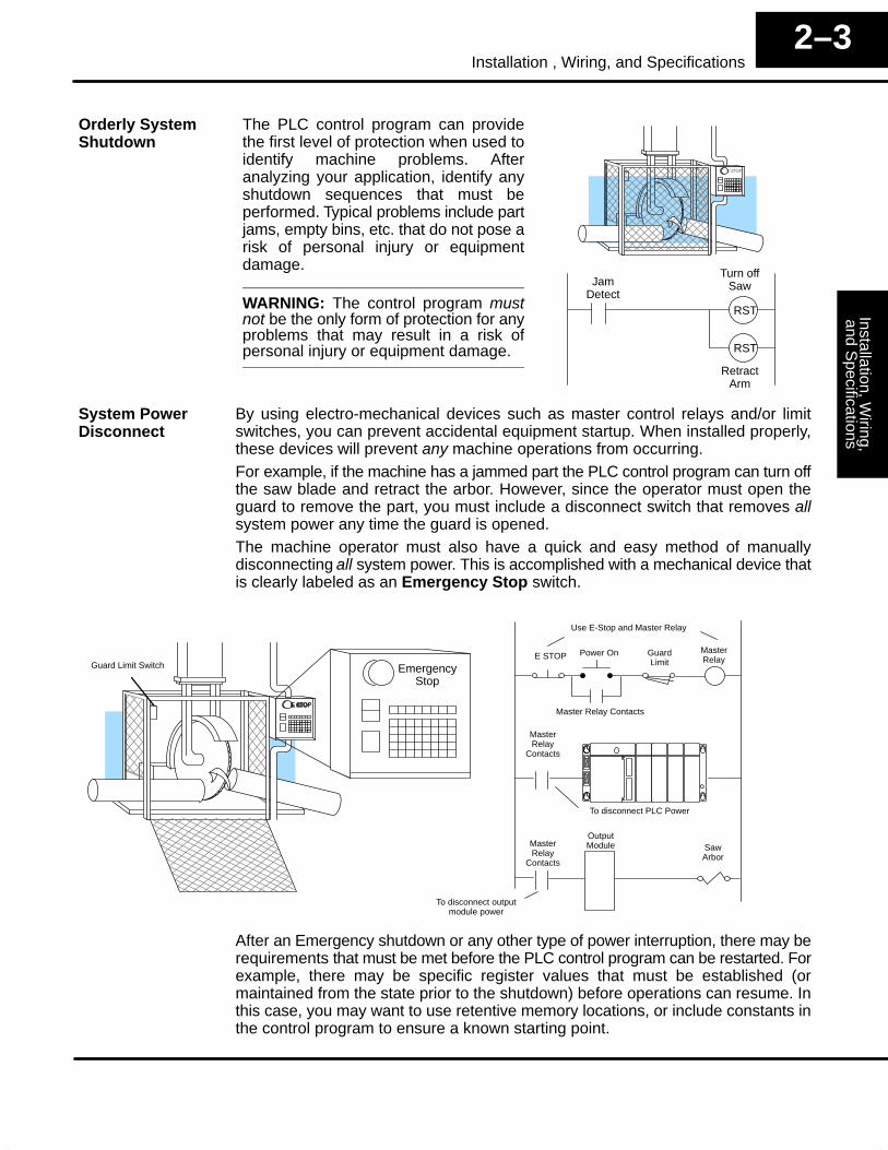
The PLC control program can providethe first level of protection when used toidentify machine problems. Afteranalyzing your application, identify anyshutdown sequences that must beperformed. Typical problems include partjams, empty bins, etc. that do not pose arisk of personal injury or equipmentdamage.
WARNING: The control program mustnot be the only form of protection for anyproblems that may result in a risk ofpersonal injury or equipment damage.
Turn offSawJam
DetectRST
RST
RetractArm
By using electro-mechanical devices such as master control relays and/or limitswitches, you can prevent accidental equipment startup. When installed properly,these devices will prevent any machine operations from occurring.For example, if the machine has a jammed part the PLC control program can turn offthe saw blade and retract the arbor. However, since the operator must open theguard to remove the part, you must include a disconnect switch that removes allsystem power any time the guard is opened.The machine operator must also have a quick and easy method of manuallydisconnecting all system power. This is accomplished with a mechanical device thatis clearly labeled as an Emergency Stop switch.
OutputModule Saw
Arbor
E STOPMasterRelay
MasterRelay
Contacts
To disconnect PLC Power
EmergencyStop
Power On
Master Relay Contacts
To disconnect outputmodule power
Use E-Stop and Master Relay
GuardLimitGuard Limit Switch
MasterRelay
Contacts
After an Emergency shutdown or any other type of power interruption, there may berequirements that must be met before the PLC control program can be restarted. Forexample, there may be specific register values that must be established (ormaintained from the state prior to the shutdown) before operations can resume. Inthis case, you may want to use retentive memory locations, or include constants inthe control program to ensure a known starting point.
Orderly SystemShutdown
System PowerDisconnect
Inst
alla
tion,
Wiri
ng,
and
Spe
cific
atio
nsIn
stal
latio
n an
dS
afet
y G
uide
lines
2–4Installation, Wiring, and Specifications
Mounting Guidelines
In addition to the panel layout guidelines, other specifications can affect theinstallation of a PLC system. Always consider the following:
• Environmental specifications• Power supply specifications• Regulatory Agency Approvals• Enclosure Selection and Component Dimensions
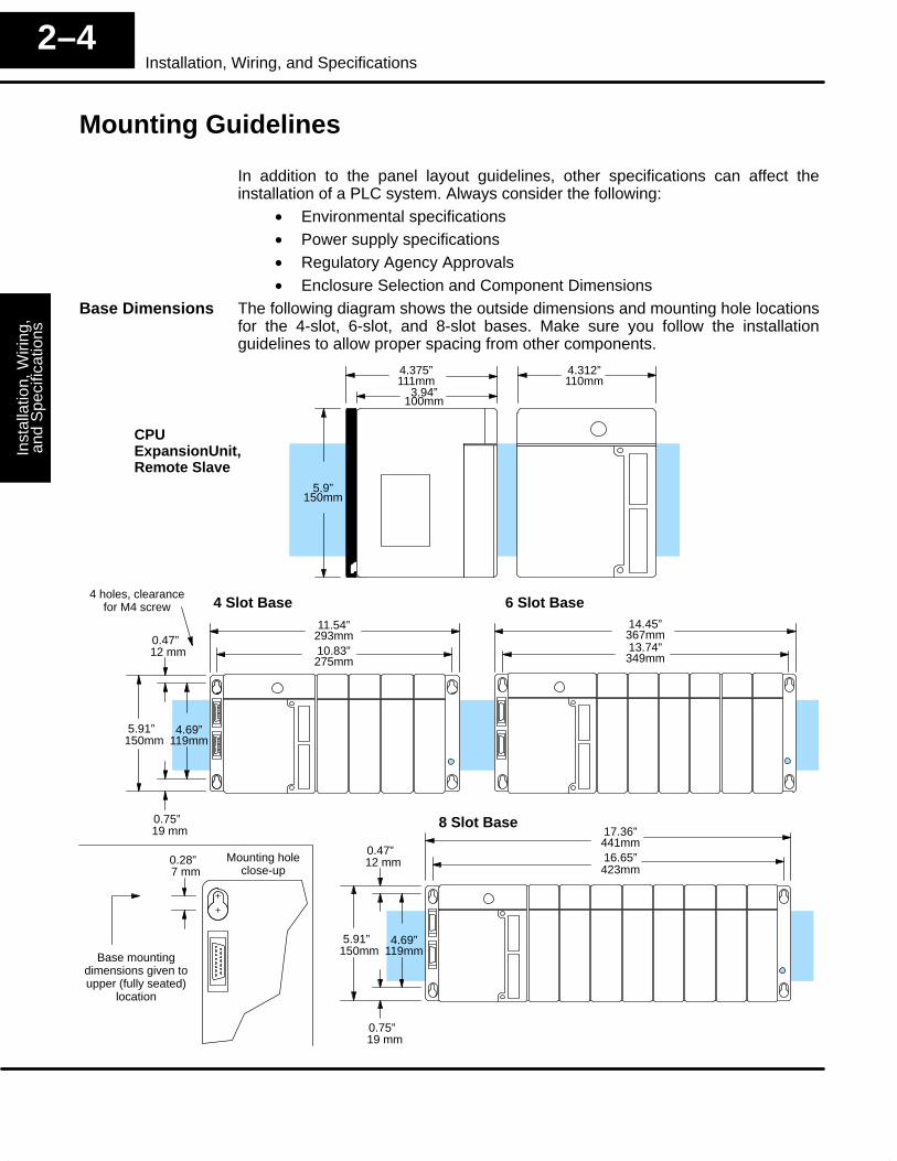
The following diagram shows the outside dimensions and mounting hole locationsfor the 4-slot, 6-slot, and 8-slot bases. Make sure you follow the installationguidelines to allow proper spacing from other components.
4 Slot Base 6 Slot Base
8 Slot Base
11.54”293mm10.83”275mm
5.91”150mm
14.45”367mm13.74”349mm
17.36”441mm16.65”423mm
CPUExpansionUnit,Remote Slave
3.94”100mm
5.9”150mm
4.375”111mm
4.69”119mm
4.312”110mm
4 holes, clearancefor M4 screw
0.75”19 mm
0.47”12 mm
5.91”150mm
4.69”119mm
0.75”19 mm
0.47”12 mm0.28”
7 mm
Base mountingdimensions given toupper (fully seated)
location
Mounting holeclose-up
Base Dimensions
Installation, Wiring,
and Specifications
Installation andS
afety Guidelines
2–5Installation , Wiring, and Specifications
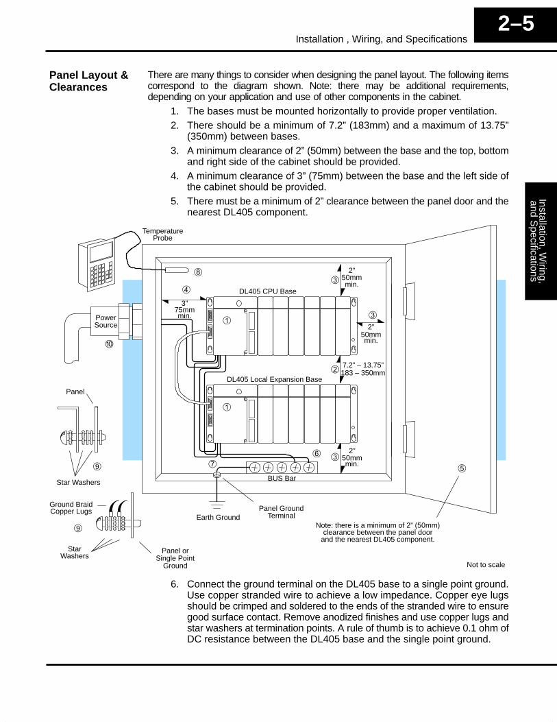
There are many things to consider when designing the panel layout. The following itemscorrespond to the diagram shown. Note: there may be additional requirements,depending on your application and use of other components in the cabinet.
1. The bases must be mounted horizontally to provide proper ventilation.2. There should be a minimum of 7.2” (183mm) and a maximum of 13.75”
(350mm) between bases.3. A minimum clearance of 2” (50mm) between the base and the top, bottom
and right side of the cabinet should be provided.4. A minimum clearance of 3” (75mm) between the base and the left side of
the cabinet should be provided.5. There must be a minimum of 2” clearance between the panel door and the
nearest DL405 component.
Earth GroundPanel Ground
Terminal
DL405 CPU Base
DL405 Local Expansion Base
PowerSource
TemperatureProbe
Star Washers
Ground BraidCopper Lugs
Panel orSingle Point
Ground
Star
�
�
BUS Bar
�
�
Note: there is a minimum of 2” (50mm)clearance between the panel door
and the nearest DL405 component.
�
3”75mmmin.
2”50mmmin.�
�
�2”
50mmmin.
�7.2” – 13.75”183 – 350mm
�
2”50mmmin.
�
�
Not to scale
Panel
Washers
6. Connect the ground terminal on the DL405 base to a single point ground.Use copper stranded wire to achieve a low impedance. Copper eye lugsshould be crimped and soldered to the ends of the stranded wire to ensuregood surface contact. Remove anodized finishes and use copper lugs andstar washers at termination points. A rule of thumb is to achieve 0.1 ohm ofDC resistance between the DL405 base and the single point ground.
Panel Layout &Clearances
Inst
alla
tion,
Wiri
ng,
and
Spe
cific
atio
nsIn
stal
latio
n an
dS
afet
y G
uide
lines
2–6Installation, Wiring, and Specifications
7. There must be a single point ground (i.e. copper bus bar) for all devices inthe panel requiring an earth ground return. The single point of ground mustbe connected to the panel ground termination.The panel ground termination must be connected to earth ground. For thisconnection you should use #12 AWG stranded copper wire as a minimum.Minimum wire sizes, color coding, and general safety practices shouldcomply with appropriate electrical codes and standards for your area.A good common ground reference (Earth ground) is essential for properoperation of the DL405, which include:
a) Installing a ground rod as close to the panel as possible.b) Connection to incoming power system ground.
8. Installations where the ambient temperature may approach the lower orupper limits of the specifications should be evaluated properly. To do thisplace a temperature probe in the panel, close the door and operate thesystem until the ambient temperature has stabilized. If the ambienttemperature is not within the operating specification for the DL405 system,measures such as installing a cooling/heating source must be taken to getthe ambient temperature within the DL405 operating specifications.
9. Device mounting bolts and ground braid termination bolts should be #10copper bolts or equivalent. Tapped holes instead of nut–bolt arrangementsshould be used whenever possible. To assure good contact on terminationareas impediments such as paint, coating or corrosion should be removedin the area of contact.
10. The DL405 system is designed to be powered by 110 VAC, 220 VAC, or 24VDC normally available throughout an industrial environment. Isolationtransformers and noise suppression devices are not normally necessary,but may be helpful in eliminating/reducing suspect power problems.
Your selection of a proper enclosure is important to ensure safe and properoperation of your DL405 system. Applications of DL405 systems vary and mayrequire additional features. The minimum considerations for enclosures include:
• Conformance to electrical standards• Protection from the elements in an industrial environment• Common ground reference• Maintenance of specified ambient temperature• Access to equipment• Security or restricted access� Sufficient space for proper installation, cooling, and maintenance
Some applications require agency approvals. The DL405 agency approvals forwhich DL405 products are submitted are;
• UL (Underwriters’ Laboratories, Inc.)• CE EMC (Electromagnetic Compatibility)• CUL (Canadian Underwriters’ Laboratories)
A complete listing of agency approvals for each product in the DL405 family isavailable in the sales catalog, or you may call 1–800–633–0405 (U.S.).
Enclosures
Agency Approvals
Installation, Wiring,
and Specifications
Installation andS
afety Guidelines
2–7Installation , Wiring, and Specifications
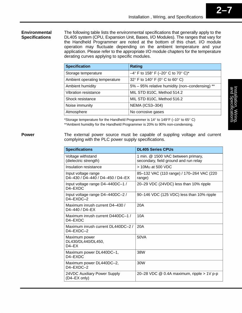
The following table lists the environmental specifications that generally apply to theDL405 system (CPU, Expansion Unit, Bases, I/O Modules). The ranges that vary forthe Handheld Programmer are noted at the bottom of this chart. I/O moduleoperation may fluctuate depending on the ambient temperature and yourapplication. Please refer to the appropriate I/O module chapters for the temperaturederating curves applying to specific modules.
Specification Rating
Storage temperature –4° F to 158° F (–20° C to 70° C)*
Ambient operating temperature 32° F to 140° F (0° C to 60° C)
Ambient humidity 5% – 95% relative humidity (non–condensing) **
Vibration resistance MIL STD 810C, Method 514.2
Shock resistance MIL STD 810C, Method 516.2
Noise immunity NEMA (ICS3–304)
Atmosphere No corrosive gases
*Storage temperature for the Handheld Programmer is 14° to 149°F (–10° to 65° C)**Ambient humidity for the Handheld Programmer is 20% to 90% non-condensing.
The external power source must be capable of suppling voltage and currentcomplying with the PLC power supply specifications.
Specifications DL405 Series CPUs
Voltage withstand(dielectric strength)
1 min. @ 1500 VAC between primary,secondary, field ground and run relay
Insulation resistance > 10M� at 500 VDC
Input voltage rangeD4–430 / D4–440 / D4–450 / D4–EX
85–132 VAC (110 range) / 170–264 VAC (220range)
Input voltage range D4–440DC–1 /D4–EXDC
20–29 VDC (24VDC) less than 10% ripple
Input voltage range D4–440DC–2 /D4–EXDC–2
90–146 VDC (125 VDC) less than 10% ripple
Maximum inrush current D4–430 /D4–440 / D4–EX
20A
Maximum inrush current D440DC–1 /D4–EXDC
10A
Maximum inrush current DL440DC–2 /D4–EXDC–2
20A
Maximum powerDL430/DL440/DL450,D4–EX
50VA
Maximum power DL440DC–1,D4–EXDC
38W
Maximum power DL440DC–2,D4–EXDC–2
30W
24VDC Auxiliary Power Supply(D4–EX only)
20–28 VDC @ 0.4A maximum, ripple > 1V p-p
EnvironmentalSpecifications
Power
Inst
alla
tion,
Wiri
ng,
and
Spe
cific
atio
nsIn
stal
latio
n an
dS
afet
y G
uide
lines
2–8Installation, Wiring, and Specifications
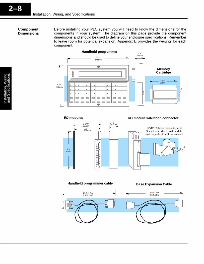
Before installing your PLC system you will need to know the dimensions for thecomponents in your system. The diagram on this page provide the componentdimensions and should be used to define your enclosure specifications. Rememberto leave room for potential expansion. Appendix E provides the weights for eachcomponent.
Handheld programmer cable
4.5 ft.(1.5m)9.1 ft. (3m)
Base Expansion Cable
1.6ft. (.5m)
I/O modules
4”100mm
5.9”150m
1.37”34.8mm4.375”
111mm
Handheld programmer1.2”
30mm
3.14”80mm
5.7”145mm
4.65”118mm
MemoryCartridge
I/O module w/Ribbon connector
3.3 ft. (1m)
NOTE: Ribbon connector andD shell extend out past moduleand may affect depth of cabinet
ComponentDimensions
Installation, Wiring,
and Specifications
Installation andS
afety Guidelines
2–9Installation , Wiring, and Specifications
Installing DL405 Bases
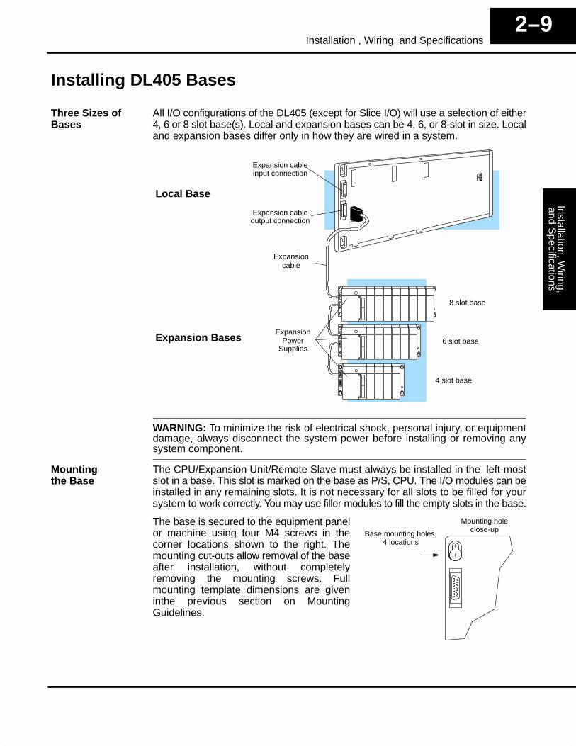
All I/O configurations of the DL405 (except for Slice I/O) will use a selection of either4, 6 or 8 slot base(s). Local and expansion bases can be 4, 6, or 8-slot in size. Localand expansion bases differ only in how they are wired in a system.
Expansion cableinput connection
Expansion cableoutput connection
Expansion
ExpansionPower
8 slot base
6 slot base
4 slot base
cable
Supplies
Local Base
Expansion Bases
WARNING: To minimize the risk of electrical shock, personal injury, or equipmentdamage, always disconnect the system power before installing or removing anysystem component.
The CPU/Expansion Unit/Remote Slave must always be installed in the left-mostslot in a base. This slot is marked on the base as P/S, CPU. The I/O modules can beinstalled in any remaining slots. It is not necessary for all slots to be filled for yoursystem to work correctly. You may use filler modules to fill the empty slots in the base.
The base is secured to the equipment panelor machine using four M4 screws in thecorner locations shown to the right. Themounting cut-outs allow removal of the baseafter installation, without completelyremoving the mounting screws. Fullmounting template dimensions are giveninthe previous section on MountingGuidelines.
Base mounting holes,4 locations
Mounting holeclose-up
Three Sizes ofBases
Mountingthe Base
Inst
alla
tion,
Wiri
ng,
and
Spe
cific
atio
nsIn
stal
latio
n an
dS
afet
y G
uide
lines
2–10Installation, Wiring, and Specifications
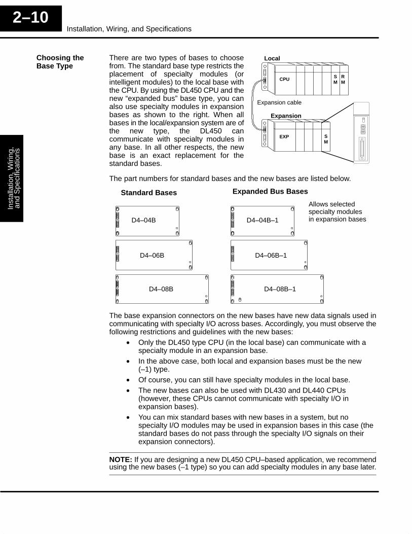
There are two types of bases to choosefrom. The standard base type restricts theplacement of specialty modules (orintelligent modules) to the local base withthe CPU. By using the DL450 CPU and thenew “expanded bus” base type, you canalso use specialty modules in expansionbases as shown to the right. When allbases in the local/expansion system are ofthe new type, the DL450 cancommunicate with specialty modules inany base. In all other respects, the newbase is an exact replacement for thestandard bases.
Local
MS
MRCPU
EXP
Expansion cable
Expansion
MS
The part numbers for standard bases and the new bases are listed below.
D4–04B
D4–06B
D4–08B
D4–04B–1
D4–06B–1
D4–08B–1
Standard Bases Expanded Bus Bases
Allows selectedspecialty modulesin expansion bases
The base expansion connectors on the new bases have new data signals used incommunicating with specialty I/O across bases. Accordingly, you must observe thefollowing restrictions and guidelines with the new bases:
• Only the DL450 type CPU (in the local base) can communicate with aspecialty module in an expansion base.
• In the above case, both local and expansion bases must be the new(–1) type.
• Of course, you can still have specialty modules in the local base.• The new bases can also be used with DL430 and DL440 CPUs
(however, these CPUs cannot communicate with specialty I/O inexpansion bases).
• You can mix standard bases with new bases in a system, but nospecialty I/O modules may be used in expansion bases in this case (thestandard bases do not pass through the specialty I/O signals on theirexpansion connectors).
NOTE: If you are designing a new DL450 CPU–based application, we recommendusing the new bases (–1 type) so you can add specialty modules in any base later.
Choosing theBase Type
Installation, Wiring,
and Specifications
Installation andS
afety Guidelines
2–11Installation , Wiring, and Specifications
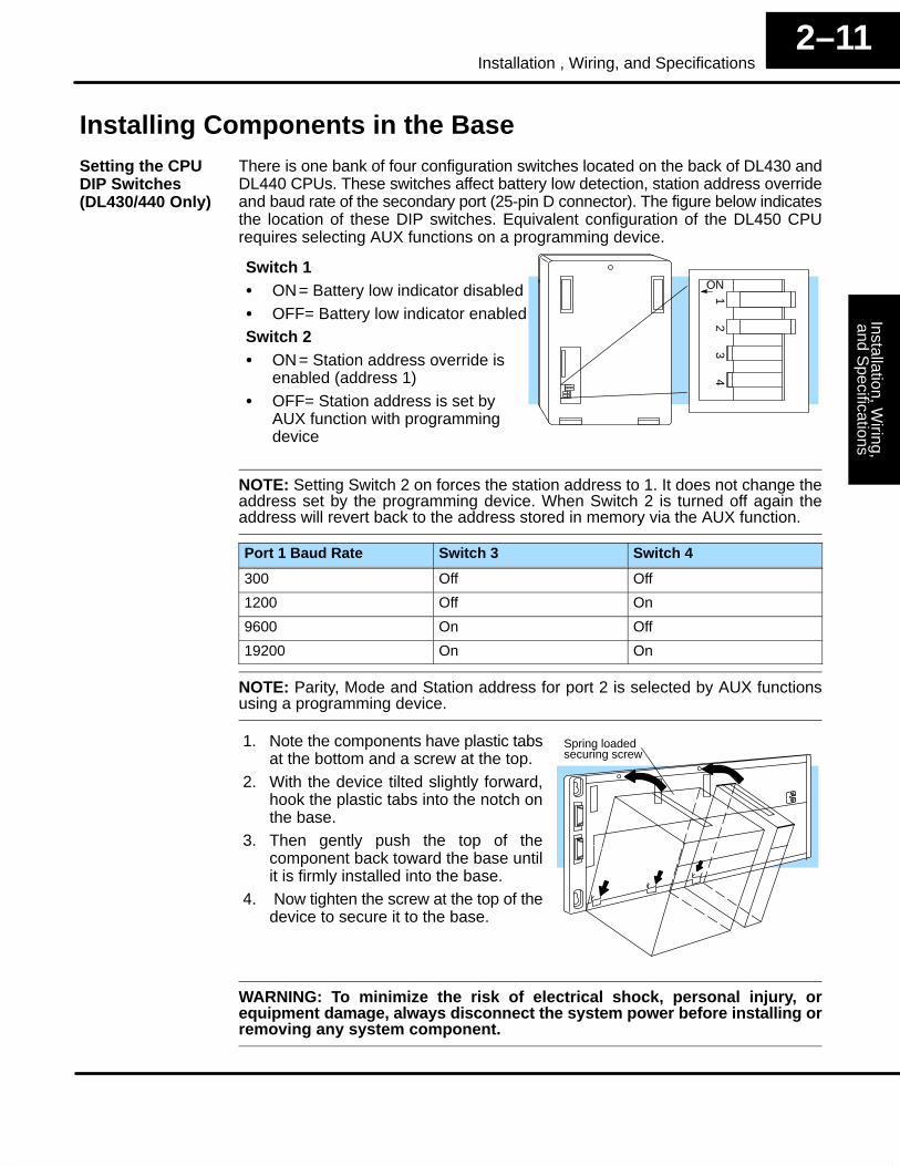
Installing Components in the BaseThere is one bank of four configuration switches located on the back of DL430 andDL440 CPUs. These switches affect battery low detection, station address overrideand baud rate of the secondary port (25-pin D connector). The figure below indicatesthe location of these DIP switches. Equivalent configuration of the DL450 CPUrequires selecting AUX functions on a programming device.
Switch 1� ON= Battery low indicator disabled� OFF= Battery low indicator enabledSwitch 2� ON= Station address override is
enabled (address 1)� OFF= Station address is set by
AUX function with programmingdevice
ON
12
34
NOTE: Setting Switch 2 on forces the station address to 1. It does not change theaddress set by the programming device. When Switch 2 is turned off again theaddress will revert back to the address stored in memory via the AUX function.
Port 1 Baud Rate Switch 3 Switch 4
300 Off Off
1200 Off On
9600 On Off
19200 On On
NOTE: Parity, Mode and Station address for port 2 is selected by AUX functionsusing a programming device.
1. Note the components have plastic tabsat the bottom and a screw at the top.
2. With the device tilted slightly forward,hook the plastic tabs into the notch onthe base.
3. Then gently push the top of thecomponent back toward the base untilit is firmly installed into the base.
4. Now tighten the screw at the top of thedevice to secure it to the base.
Spring loadedsecuring screw
WARNING: To minimize the risk of electrical shock, personal injury, orequipment damage, always disconnect the system power before installing orremoving any system component.
Setting the CPUDIP Switches(DL430/440 Only)
Inst
alla
tion,
Wiri
ng,
and
Spe
cific
atio
nsIn
stal
latio
n an
dS
afet
y G
uide
lines
2–12Installation, Wiring, and Specifications
CPU and Expansion Unit Wiring Guidelines
The main power terminal connections are under the front covers of the DL405 CPUsand Expansion Units. The list below describes the function of each of the terminalscrews. Most of the terminal screws are identical between the CPU and theExpansion Unit. If the terminal screw only applies to one of the units it will be noted.
• Run Relay – (CPU only) indicates to an external device when the CPUis in Run Mode by contact closure. Its normally-open contacts can alsoremove power from critical I/O points if CPU comes out of Run mode.
• 24VDC Auxiliary Power – can be used to power field devices or I/Omodules requiring external power. It supplies up to 400 mA of current at20–28VDC, ripple less than 1 V P-P. (Not available on DC CPUs.)
• Logic Ground – internal ground to the system which can be tied to fielddevices/communication ports to unite ground signals.
• Chassis Ground – where earth ground is connected to the unit.• AC Power –where the line (hot) and the neutral (common) connections
are made to the CPU/Expansion Unit. (This is also where the DC powersource is connected for the 24/125 VDC CPU. The positive connectionis tied to line and the negative connection is tied to ground.)
• 110/220 Voltage Select – a shunt across two of the terminalsdetermines the voltage selection. Install the shunt to select 110VACinput power, and remove the shunt to select 220VAC power input (theshunt is not required for DC-powered CPUs or Expansion Units.)
WARNING: Damage will occur to the power supply if 220 VAC is connected to theterminal connections with the 115 VAC shunt installed. Once the power wiring isconnected, install the protective cover to avoid risk of accidental shock.
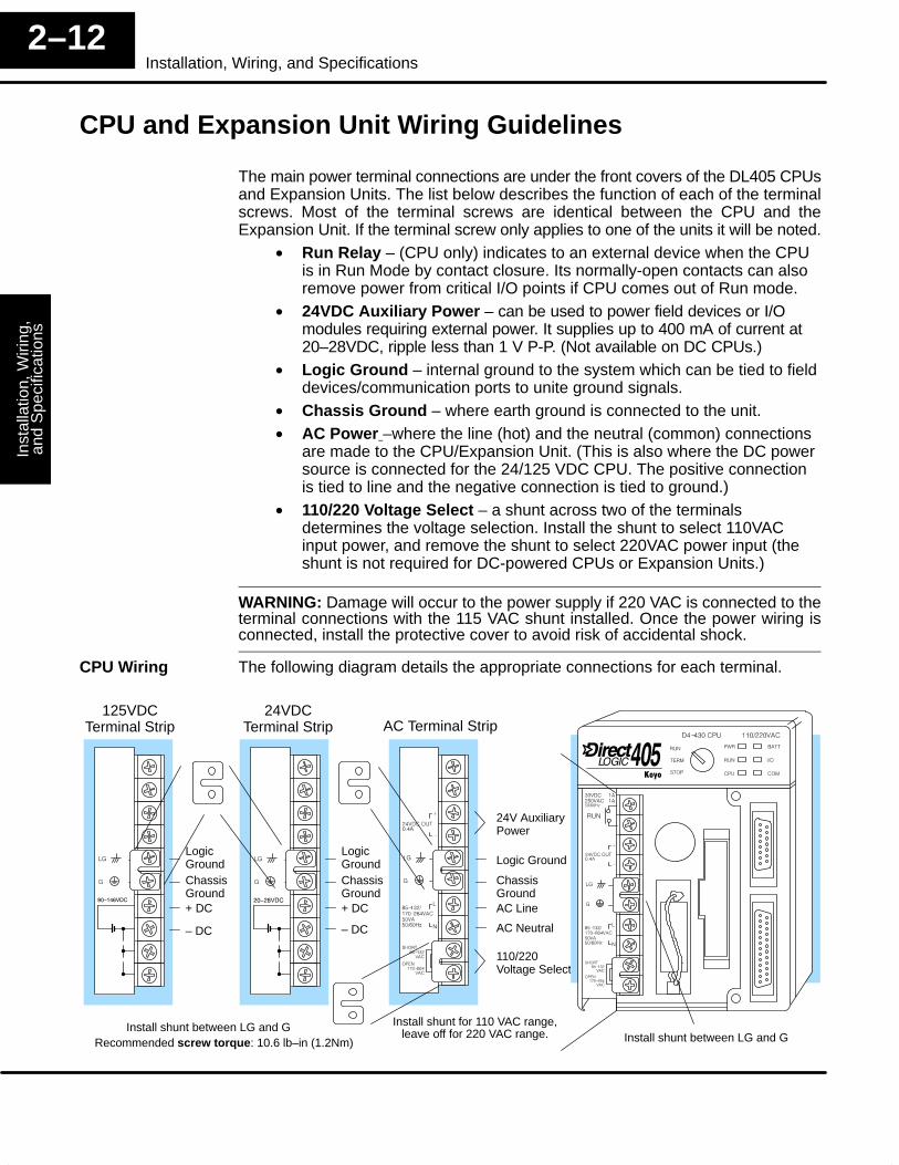
The following diagram details the appropriate connections for each terminal.
LogicGroundChassisGround
AC Terminal Strip
24V AuxiliaryPower
Logic Ground
ChassisGround
110/220Voltage Select
LogicGroundChassisGround
24VDCTerminal Strip
125VDCTerminal Strip
+ DC
– DC
+ DC
– DC
AC Line
AC Neutral
Install shunt for 110 VAC range,leave off for 220 VAC range. Install shunt between LG and G
Install shunt between LG and GRecommended screw torque: 10.6 lb–in (1.2Nm)
CPU Wiring
Installation, Wiring,
and Specifications
Installation andS
afety Guidelines
2–13Installation , Wiring, and Specifications
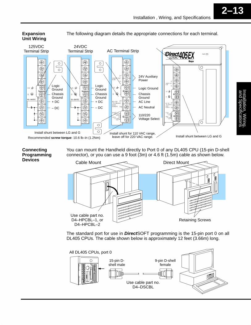
The following diagram details the appropriate connections for each terminal.
LogicGroundChassisGround
AC Terminal Strip
24V AuxiliaryPower
Logic Ground
ChassisGround
110/220Voltage Select
LogicGroundChassisGround
24VDCTerminal Strip
125VDCTerminal Strip
+ DC
– DC
+ DC
– DC
AC Line
AC Neutral
Install shunt for 110 VAC range,leave off for 220 VAC range. Install shunt between LG and G
Install shunt between LG and G
Recommended screw torque: 10.6 lb–in (1.2Nm)
You can mount the Handheld directly to Port 0 of any DL405 CPU (15-pin D-shellconnector), or you can use a 9 foot (3m) or 4.6 ft (1.5m) cable as shown below.
Retaining Screws
Cable Mount Direct Mount
Use cable part no.D4–HPCBL–1, or
D4–HPCBL–2
The standard port for use in DirectSOFT programming is the 15-pin port 0 on allDL405 CPUs. The cable shown below is approximately 12 feet (3.66m) long.
Use cable part no.D4–DSCBL
9-pin D-shellfemale
All DL405 CPUs, port 0
15-pin D-shell male
ExpansionUnit Wiring
ConnectingProgrammingDevices
Inst
alla
tion,
Wiri
ng,
and
Spe
cific
atio
nsIn
stal
latio
n an
dS
afet
y G
uide
lines
2–14Installation, Wiring, and Specifications
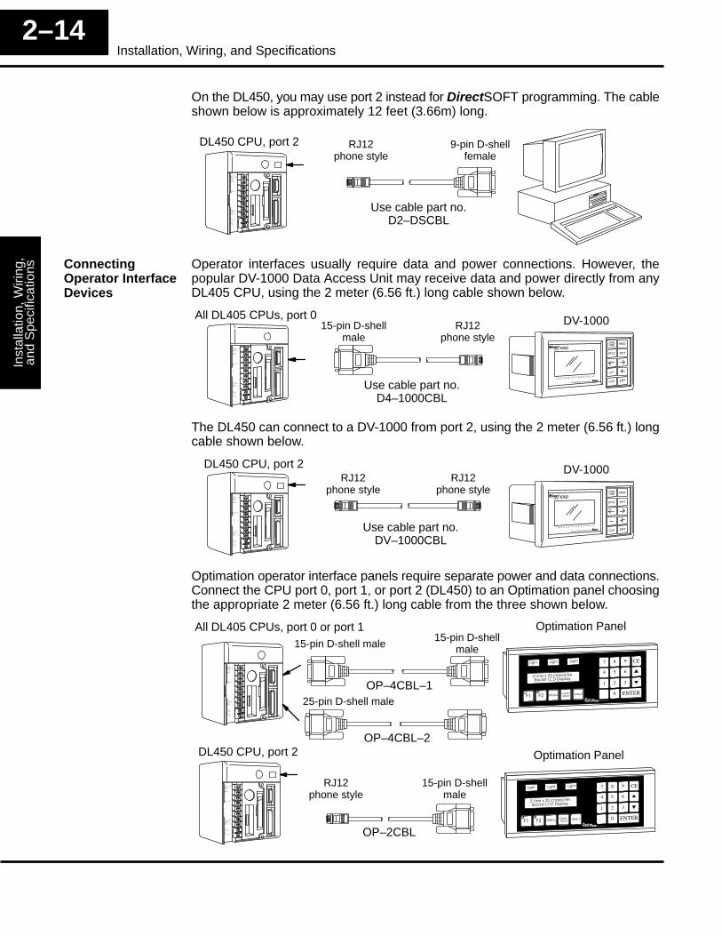
On the DL450, you may use port 2 instead for DirectSOFT programming. The cableshown below is approximately 12 feet (3.66m) long.
Use cable part no.D2–DSCBL
9-pin D-shellfemale
RJ12phone style
DL450 CPU, port 2
Operator interfaces usually require data and power connections. However, thepopular DV-1000 Data Access Unit may receive data and power directly from anyDL405 CPU, using the 2 meter (6.56 ft.) long cable shown below.
All DL405 CPUs, port 0 DV-1000
Use cable part no.D4–1000CBL
15-pin D-shellmale
RJ12phone style
The DL450 can connect to a DV-1000 from port 2, using the 2 meter (6.56 ft.) longcable shown below.
DL450 CPU, port 2 DV-1000
Use cable part no.DV–1000CBL
RJ12phone style
RJ12phone style
Optimation operator interface panels require separate power and data connections.Connect the CPU port 0, port 1, or port 2 (DL450) to an Optimation panel choosingthe appropriate 2 meter (6.56 ft.) long cable from the three shown below.
Optimation Panel
OP–4CBL–1
15-pin D-shellmale
All DL405 CPUs, port 0 or port 115-pin D-shell male
Optimation Panel
OP–4CBL–2
15-pin D-shellmale
DL450 CPU, port 2
25-pin D-shell male
RJ12phone style
OP–2CBL
ConnectingOperator InterfaceDevices
Installation, Wiring,
and Specifications
Installation andS
afety Guidelines
2–15Installation , Wiring, and Specifications
I/O Wiring Strategies
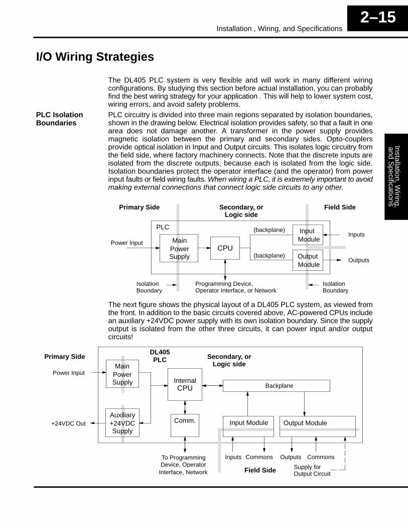
The DL405 PLC system is very flexible and will work in many different wiringconfigurations. By studying this section before actual installation, you can probablyfind the best wiring strategy for your application . This will help to lower system cost,wiring errors, and avoid safety problems.PLC circuitry is divided into three main regions separated by isolation boundaries,shown in the drawing below. Electrical isolation provides safety, so that a fault in onearea does not damage another. A transformer in the power supply providesmagnetic isolation between the primary and secondary sides. Opto-couplersprovide optical isolation in Input and Output circuits. This isolates logic circuitry fromthe field side, where factory machinery connects. Note that the discrete inputs areisolated from the discrete outputs, because each is isolated from the logic side.Isolation boundaries protect the operator interface (and the operator) from powerinput faults or field wiring faults. When wiring a PLC, it is extremely important to avoidmaking external connections that connect logic side circuits to any other.
CPU
InputModuleMain
PowerSupply
Inputs
Outputs
Power Input
OutputModule
Primary Side Secondary, orLogic side
Field Side
PLC
Programming Device,Operator Interface, or Network
IsolationBoundary
IsolationBoundary
(backplane)
(backplane)
The next figure shows the physical layout of a DL405 PLC system, as viewed fromthe front. In addition to the basic circuits covered above, AC-powered CPUs includean auxiliary +24VDC power supply with its own isolation boundary. Since the supplyoutput is isolated from the other three circuits, it can power input and/or outputcircuits!
Input Module
CPU
Comm.
MainPowerSupply
Auxiliary+24VDCSupply
To ProgrammingDevice, Operator
Inputs Commons CommonsOutputs
+24VDC Out
Power Input
PLCDL405
Interface, Network
Output Module
InternalBackplane
Supply forOutput Circuit
Primary Side Secondary, orLogic side
Field Side
PLC IsolationBoundaries
Inst
alla
tion,
Wiri
ng,
and
Spe
cific
atio
nsIn
stal
latio
n an
dS
afet
y G
uide
lines
2–16Installation, Wiring, and Specifications
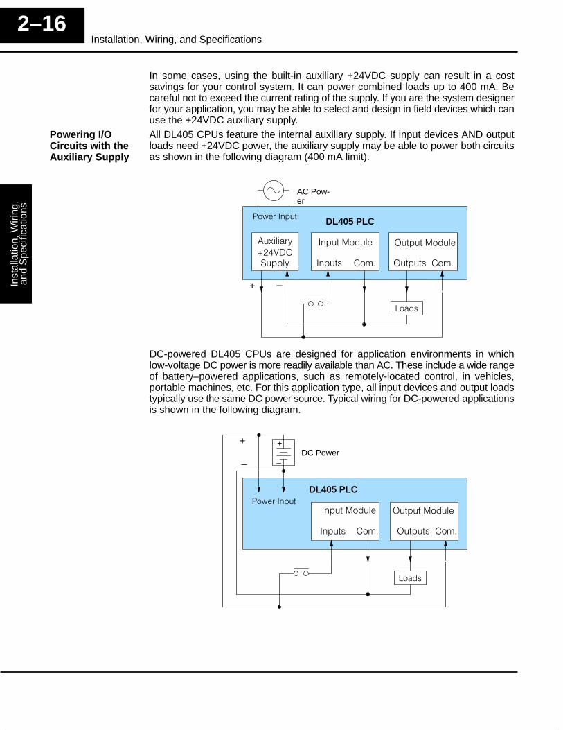
In some cases, using the built-in auxiliary +24VDC supply can result in a costsavings for your control system. It can power combined loads up to 400 mA. Becareful not to exceed the current rating of the supply. If you are the system designerfor your application, you may be able to select and design in field devices which canuse the +24VDC auxiliary supply.All DL405 CPUs feature the internal auxiliary supply. If input devices AND outputloads need +24VDC power, the auxiliary supply may be able to power both circuitsas shown in the following diagram (400 mA limit).
�����������)�$��� �
*+�,������
!�-� ����� DL405 PLC
'�����������
����
AC Pow-er
+ –
����� �� � '����� �� �
DC-powered DL405 CPUs are designed for application environments in whichlow-voltage DC power is more readily available than AC. These include a wide rangeof battery–powered applications, such as remotely-located control, in vehicles,portable machines, etc. For this application type, all input devices and output loadstypically use the same DC power source. Typical wiring for DC-powered applicationsis shown in the following diagram.
�����������!�-� �����
DL405 PLC
'�����������
����
DC Power+
–
+
–
����� �� � '����� �� �
Powering I/OCircuits with theAuxiliary Supply
Installation, Wiring,
and Specifications
Installation andS
afety Guidelines
2–17Installation , Wiring, and Specifications
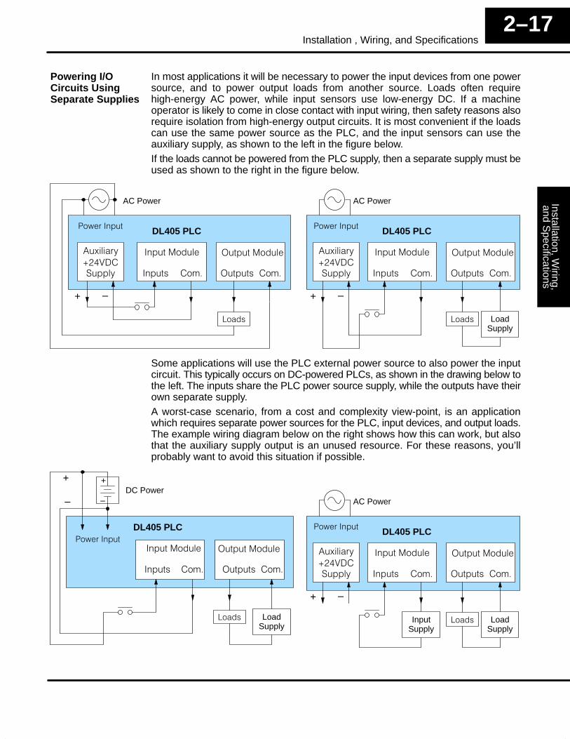
In most applications it will be necessary to power the input devices from one powersource, and to power output loads from another source. Loads often requirehigh-energy AC power, while input sensors use low-energy DC. If a machineoperator is likely to come in close contact with input wiring, then safety reasons alsorequire isolation from high-energy output circuits. It is most convenient if the loadscan use the same power source as the PLC, and the input sensors can use theauxiliary supply, as shown to the left in the figure below.If the loads cannot be powered from the PLC supply, then a separate supply must beused as shown to the right in the figure below.
�����������)�$��� �
*+�,������
!�-� ����� DL405 PLC
'�����������
����
AC Power
+ –
����� �� � '����� �� �
�����������)�$��� �
*+�,������
!�-� ����� DL405 PLC
'�����������
����
AC Power
+ –
����� �� � '����� �� �
LoadSupply
Some applications will use the PLC external power source to also power the inputcircuit. This typically occurs on DC-powered PLCs, as shown in the drawing below tothe left. The inputs share the PLC power source supply, while the outputs have theirown separate supply.A worst-case scenario, from a cost and complexity view-point, is an applicationwhich requires separate power sources for the PLC, input devices, and output loads.The example wiring diagram below on the right shows how this can work, but alsothat the auxiliary supply output is an unused resource. For these reasons, you’llprobably want to avoid this situation if possible.
�����������!�-� �����
DL405 PLC
'�����������
����
DC Power+
–
+
–
����� �� � '����� �� �
LoadSupply
�����������)�$��� �
*+�,������
!�-� ����� DL405 PLC
'�����������
����
AC Power
+ –
����� �� � '����� �� �
LoadSupply
InputSupply
Powering I/OCircuits UsingSeparate Supplies
Inst
alla
tion,
Wiri
ng,
and
Spe
cific
atio
nsIn
stal
latio
n an
dS
afet
y G
uide
lines
2–18Installation, Wiring, and Specifications
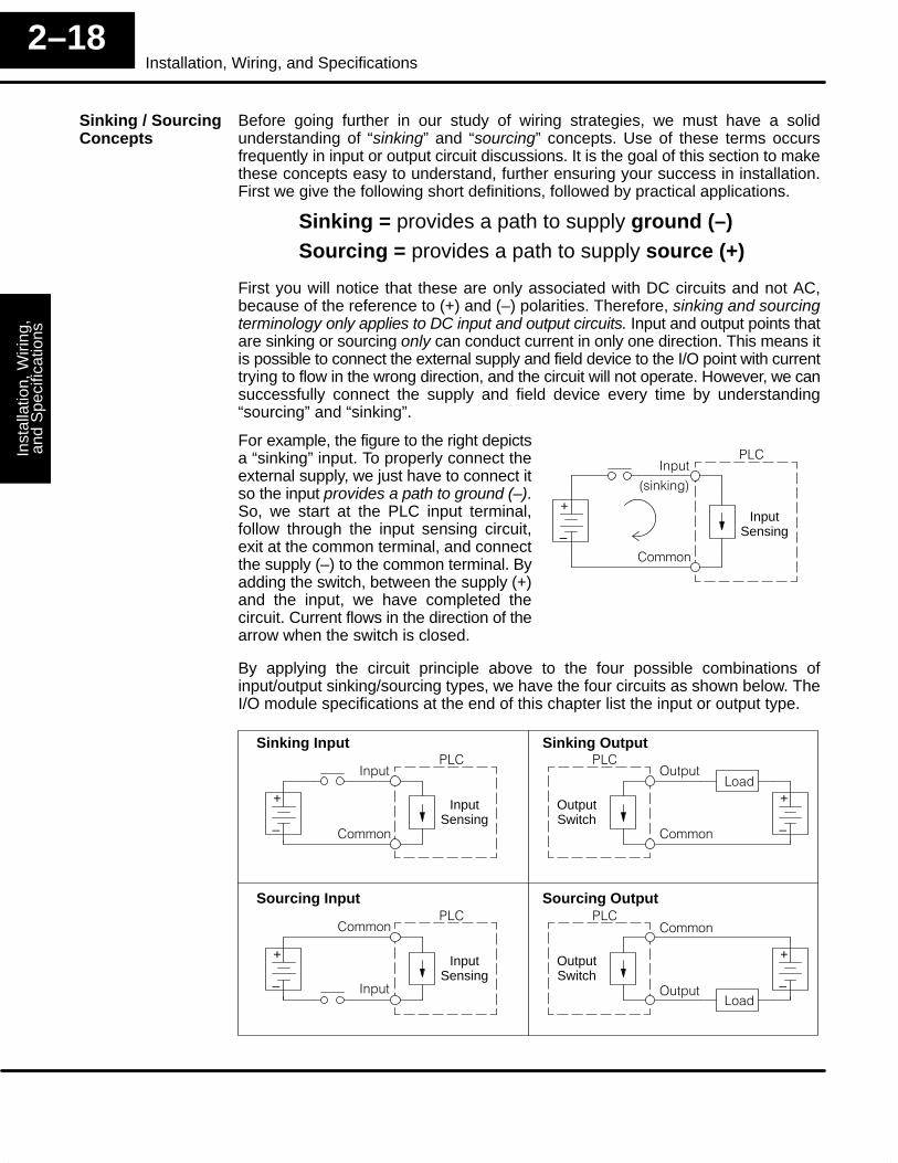
Before going further in our study of wiring strategies, we must have a solidunderstanding of “sinking” and “sourcing” concepts. Use of these terms occursfrequently in input or output circuit discussions. It is the goal of this section to makethese concepts easy to understand, further ensuring your success in installation.First we give the following short definitions, followed by practical applications.
Sinking = provides a path to supply ground (–)Sourcing = provides a path to supply source (+)
First you will notice that these are only associated with DC circuits and not AC,because of the reference to (+) and (–) polarities. Therefore, sinking and sourcingterminology only applies to DC input and output circuits. Input and output points thatare sinking or sourcing only can conduct current in only one direction. This means itis possible to connect the external supply and field device to the I/O point with currenttrying to flow in the wrong direction, and the circuit will not operate. However, we cansuccessfully connect the supply and field device every time by understanding“sourcing” and “sinking”.
For example, the figure to the right depictsa “sinking” input. To properly connect theexternal supply, we just have to connect itso the input provides a path to ground (–).So, we start at the PLC input terminal,follow through the input sensing circuit,exit at the common terminal, and connectthe supply (–) to the common terminal. Byadding the switch, between the supply (+)and the input, we have completed thecircuit. Current flows in the direction of thearrow when the switch is closed.
+
–
InputSensing
!������
�� ��
.���/���0
By applying the circuit principle above to the four possible combinations ofinput/output sinking/sourcing types, we have the four circuits as shown below. TheI/O module specifications at the end of this chapter list the input or output type.
+
–
InputSensing
���
Sinking Input Sinking Output
Sourcing Input Sourcing Output
!������
�� ��
+
–
OutputSwitch
!��'����
�� ��
+
–
InputSensing
���
!��
����
�� ��
+
–
OutputSwitch
!��
'����
�� ��
Sinking / SourcingConcepts
Installation, Wiring,
and Specifications
Installation andS
afety Guidelines
2–19Installation , Wiring, and Specifications
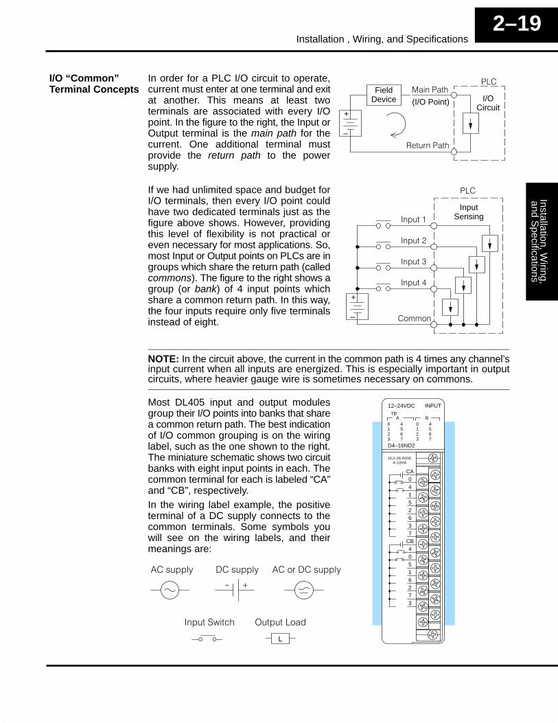
In order for a PLC I/O circuit to operate,current must enter at one terminal and exitat another. This means at least twoterminals are associated with every I/Opoint. In the figure to the right, the Input orOutput terminal is the main path for thecurrent. One additional terminal mustprovide the return path to the powersupply.
+
–
I/OCircuit
!��
(I/O Point)
1��� ��!��
FieldDevice
����!��
If we had unlimited space and budget forI/O terminals, then every I/O point couldhave two dedicated terminals just as thefigure above shows. However, providingthis level of flexibility is not practical oreven necessary for most applications. So,most Input or Output points on PLCs are ingroups which share the return path (calledcommons). The figure to the right shows agroup (or bank) of 4 input points whichshare a common return path. In this way,the four inputs require only five terminalsinstead of eight.
+
–
InputSensing
!��
������
�� ��
�����2
�����+
�����3
NOTE: In the circuit above, the current in the common path is 4 times any channel’sinput current when all inputs are energized. This is especially important in outputcircuits, where heavier gauge wire is sometimes necessary on commons.
Most DL405 input and output modulesgroup their I/O points into banks that sharea common return path. The best indicationof I/O common grouping is on the wiringlabel, such as the one shown to the right.The miniature schematic shows two circuitbanks with eight input points in each. Thecommon terminal for each is labeled “CA”and “CB”, respectively.In the wiring label example, the positiveterminal of a DC supply connects to thecommon terminals. Some symbols youwill see on the wiring labels, and theirmeanings are:
0123
4567
ATB
12–24VDC
D4–16ND2
0123
4567
B
INPUT
CA04152637
CB40516273
10.2–26.4VDC4–12mA
L
)������ )��� ��������
������-��(� '��������
�������
*4
I/O “Common”Terminal Concepts
Inst
alla
tion,
Wiri
ng,
and
Spe
cific
atio
nsIn
stal
latio
n an
dS
afet
y G
uide
lines
2–20Installation, Wiring, and Specifications
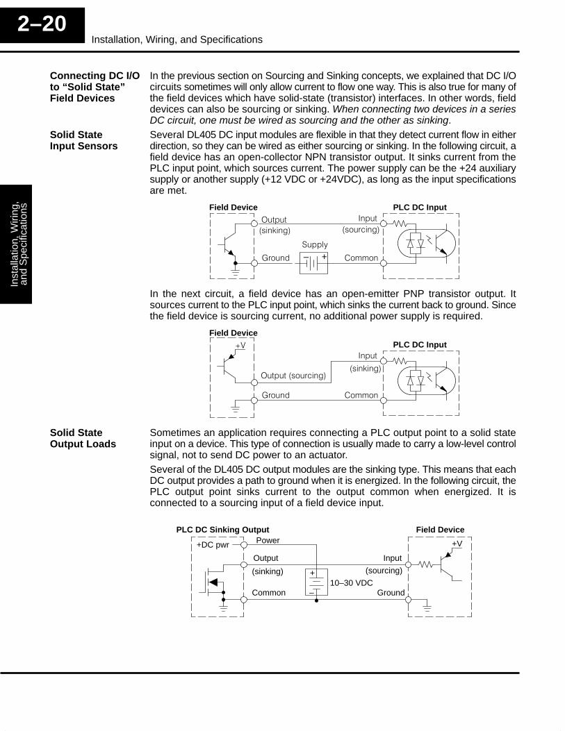
In the previous section on Sourcing and Sinking concepts, we explained that DC I/Ocircuits sometimes will only allow current to flow one way. This is also true for many ofthe field devices which have solid-state (transistor) interfaces. In other words, fielddevices can also be sourcing or sinking. When connecting two devices in a seriesDC circuit, one must be wired as sourcing and the other as sinking.Several DL405 DC input modules are flexible in that they detect current flow in eitherdirection, so they can be wired as either sourcing or sinking. In the following circuit, afield device has an open-collector NPN transistor output. It sinks current from thePLC input point, which sources current. The power supply can be the +24 auxiliarysupply or another supply (+12 VDC or +24VDC), as long as the input specificationsare met.
Field Device
+–
PLC DC Input
'����
� ����
����
�� ��
����
.���/���0 .��� (���0
In the next circuit, a field device has an open-emitter PNP transistor output. Itsources current to the PLC input point, which sinks the current back to ground. Sincethe field device is sourcing current, no additional power supply is required.
Field DevicePLC DC Input
'�����.��� (���0
� ����
����
�� ��
*,
.���/���0
Sometimes an application requires connecting a PLC output point to a solid stateinput on a device. This type of connection is usually made to carry a low-level controlsignal, not to send DC power to an actuator.Several of the DL405 DC output modules are the sinking type. This means that eachDC output provides a path to ground when it is energized. In the following circuit, thePLC output point sinks current to the output common when energized. It isconnected to a sourcing input of a field device input.
Field Device
Output
Ground
Input
Common
+V
PLC DC Sinking Output
+DC pwr
+
–
(sourcing)(sinking)
Power
10–30 VDC
Connecting DC I/Oto “Solid State”Field Devices
Solid StateInput Sensors
Solid StateOutput Loads
Installation, Wiring,
and Specifications
Installation andS
afety Guidelines
2–21Installation , Wiring, and Specifications
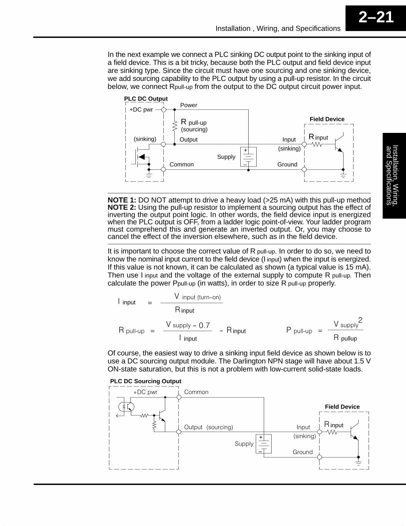
In the next example we connect a PLC sinking DC output point to the sinking input ofa field device. This is a bit tricky, because both the PLC output and field device inputare sinking type. Since the circuit must have one sourcing and one sinking device,we add sourcing capability to the PLC output by using a pull-up resistor. In the circuitbelow, we connect Rpull-up from the output to the DC output circuit power input.
Field Device
Output
Ground
Input
Common
PLC DC Output
+DC pwr
+
–
(sourcing)
(sinking)
Power
(sinking)
pull-up
Supply
R
inputR
NOTE 1: DO NOT attempt to drive a heavy load (>25 mA) with this pull-up methodNOTE 2: Using the pull-up resistor to implement a sourcing output has the effect ofinverting the output point logic. In other words, the field device input is energizedwhen the PLC output is OFF, from a ladder logic point-of-view. Your ladder programmust comprehend this and generate an inverted output. Or, you may choose tocancel the effect of the inversion elsewhere, such as in the field device.
It is important to choose the correct value of R pull-up. In order to do so, we need toknow the nominal input current to the field device (I input) when the input is energized.If this value is not known, it can be calculated as shown (a typical value is 15 mA).Then use I input and the voltage of the external supply to compute R pull-up. Thencalculate the power Ppull-up (in watts), in order to size R pull-up properly.
���5�1 input16����, �4���7
4input�
input� 6�����.�� �4��0,
input1
���5�! 6����,
+
pullup1
Of course, the easiest way to drive a sinking input field device as shown below is touse a DC sourcing output module. The Darlington NPN stage will have about 1.5 VON-state saturation, but this is not a problem with low-current solid-state loads.
Field Device
'����
� ����
����
�� ��
PLC DC Sourcing Output
*���-
+
–
.��� (���0
.���/���0
����
input1
Inst
alla
tion,
Wiri
ng,
and
Spe
cific
atio
nsIn
stal
latio
n an
dS
afet
y G
uide
lines
2–22Installation, Wiring, and Specifications
Four output modules in the DL405 I/O family feature relay outputs: D4–08TR,F4–08TRS–1, F4–08TRS–2, D4–16TR. Relays are best for the followingapplications:
• Loads that require higher currents than the solid-state outputs candeliver
• Cost-sensitive applications• Some output channels need isolation from other outputs (such as when
some loads require different voltages than other loads)
Some applications in which NOT to use relays:
• Loads that require currents under 10 mA� Loads which must be switched at high speed or heavy duty cycle
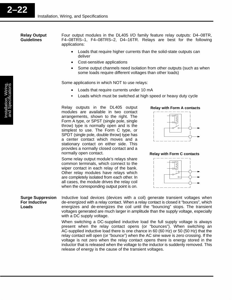
Relay outputs in the DL405 outputmodules are available in two contactarrangements, shown to the right. TheForm A type, or SPST (single pole, singlethrow) type is normally open and is thesimplest to use. The Form C type, orSPDT (single pole, double throw) type hasa center contact which moves and astationary contact on either side. Thisprovides a normally closed contact and anormally open contact.Some relay output module’s relays sharecommon terminals, which connect to thewiper contact in each relay of the bank.Other relay modules have relays whichare completely isolated from each other. Inall cases, the module drives the relay coilwhen the corresponding output point is on.
Relay with Form A contacts
Relay with Form C contacts
Inductive load devices (devices with a coil) generate transient voltages whende-energized with a relay contact. When a relay contact is closed it “bounces”, whichenergizes and de-energizes the coil until the “bouncing” stops. The transientvoltages generated are much larger in amplitude than the supply voltage, especiallywith a DC supply voltage.When switching a DC-supplied inductive load the full supply voltage is alwayspresent when the relay contact opens (or “bounces”). When switching anAC-supplied inductive load there is one chance in 60 (60 Hz) or 50 (50 Hz) that therelay contact will open (or “bounce”) when the AC sine wave is zero crossing. If thevoltage is not zero when the relay contact opens there is energy stored in theinductor that is released when the voltage to the inductor is suddenly removed. Thisrelease of energy is the cause of the transient voltages.
Relay OutputGuidelines
Surge SuppresionFor InductiveLoads
Installation, Wiring,
and Specifications
Installation andS
afety Guidelines
2–23Installation , Wiring, and Specifications
When inductive load devices (motors, motor starters, interposing relays, solenoids,valves, etc.) are controlled with relay contacts, it is recommended that a surgesuppression device be connected directly across the coil of the field device. If theinductive device has plug-type connectors, the suppression device can be installedon the terminal block of the relay output.
Transient Voltage Suppressors (TVS or transorb) provide the best surge andtransient suppression of AC and DC powered coils, providing the fastest responsewith the smallest overshoot.
Metal Oxide Varistors (MOV) provide the next best surge and transientsuppression of AC and DC powered coils.
+24 VDC –24 VDC
Module Relay Contact
–324 VDC
+24 VDC
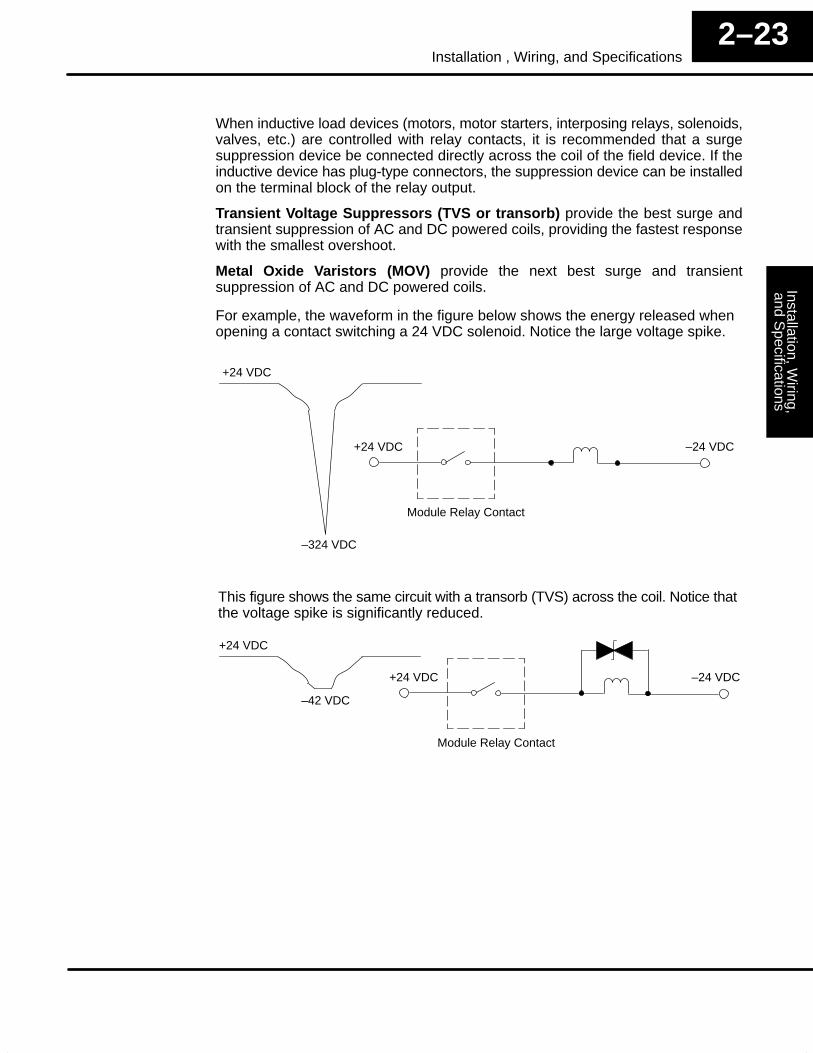
For example, the waveform in the figure below shows the energy released whenopening a contact switching a 24 VDC solenoid. Notice the large voltage spike.
This figure shows the same circuit with a transorb (TVS) across the coil. Notice thatthe voltage spike is significantly reduced.
+24 VDC –24 VDC
Module Relay Contact
–42 VDC
+24 VDC
Inst
alla
tion,
Wiri
ng,
and
Spe
cific
atio
nsIn
stal
latio
n an
dS
afet
y G
uide
lines
2–24Installation, Wiring, and Specifications
Use the following table to help select a TVS or MOV suppressor for your applicationbased on the inductive load voltage.
hhVendor / Catalog Type (TVS, MOV, Diode) Inductive Load Voltage Part Number
General Instrument Transient Voltage Suppressors, LiteOnDiodes; from DigiKeyCatalog; Phone:1-800-344-4539
TVS
TVS
TVS
Diode
110/120 VAC
220/240 VAC
12/24 VDC or VAC
12/24 VDC or VAC
P6KE180CAGICT–ND
P6KE350CA
P6K30CAGICT–ND
1N4004CT–ND
Harris Metal Oxide Varistors; from NewarkCatalog; Phone:1-800-463-9275
MOV
MOV
110/120 VAC
220/240 VAC
V150LA20C
V250LA20C
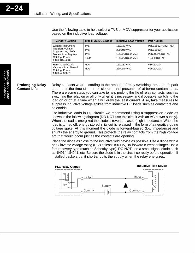
Relay contacts wear according to the amount of relay switching, amount of sparkcreated at the time of open or closure, and presence of airborne contaminants.There are some steps you can take to help prolong the life of relay contacts, such asswitching the relay on or off only when it is necessary, and if possible, switching theload on or off at a time when it will draw the least current. Also, take measures tosuppress inductive voltage spikes from inductive DC loads such as contactors andsolenoids.For inductive loads in DC circuits we recommend using a suppression diode asshown in the following diagram (DO NOT use this circuit with an AC power supply).When the load is energized the diode is reverse-biased (high impedance). When theload is turned off, energy stored in its coil is released in the form of a negative-goingvoltage spike. At this moment the diode is forward-biased (low impedance) andshunts the energy to ground. This protects the relay contacts from the high voltagearc that would occur just as the contacts are opening.Place the diode as close to the inductive field device as possible. Use a diode with apeak inverse voltage rating (PIV) at least 100 PIV, 3A forward current or larger. Use afast-recovery type (such as Schottky type). DO NOT use a small-signal diode suchas 1N914, 1N941, etc. Be sure the diode is in the circuit correctly before operation. Ifinstalled backwards, it short-circuits the supply when the relay energizes.
Inductive Field Device
+ –
PLC Relay Output
'����
�� ��
����
�� ��
����
Prolonging RelayContact Life
Installation, Wiring,
and Specifications
Installation andS
afety Guidelines
2–25Installation , Wiring, and Specifications
Another method of surge suppression is to use a resistor and capacitor (RC)snubber network. The RC network must be located close to the relay module outputconnector. To find the values for the RC snubber network, first determine the voltageacross the contacts when open, and the current through them when closed. If theload supply is AC, then convert the current and voltage values to peak values:Now we are ready to calculate values for R and C, according to the formulas:
R (�)�6C (�F) =10
I2
V
10 x I x, where x=
50
V1 +
C minimum = 0.001 �F, the voltage rating of C must be � V, non-polarizedR minimum = 0.5 �, 1/2 W, tolerance is � 5%
For example, suppose a relay contact drives a load at 120VAC, 1/2 A. Since thisexample has an AC power source, we first, we calculate the peak values:
Ipeak = Irms x 1.414, = 0.5 x 1.414 = 0.707 Amperes
Vpeak = Vrms x 1.414 = 120 x 1.414 = 169.7 Volts
Now, finding the values of R and C, we have:
R (�)�6
C (�F) =10
I2
V
10 x I x, where x=
50
V1 +
=10
0.7072
= 0.05 �F, voltage rating � 170 Volts
x=50
169.71 + = 1.29 R (�)�6
169.7
10 x 0.707 1.296�38��9�3&+�%9�� 5%
Inst
alla
tion,
Wiri
ng,
and
Spe
cific
atio
nsIn
stal
latio
n an
dS
afet
y G
uide
lines
2–26Installation, Wiring, and Specifications
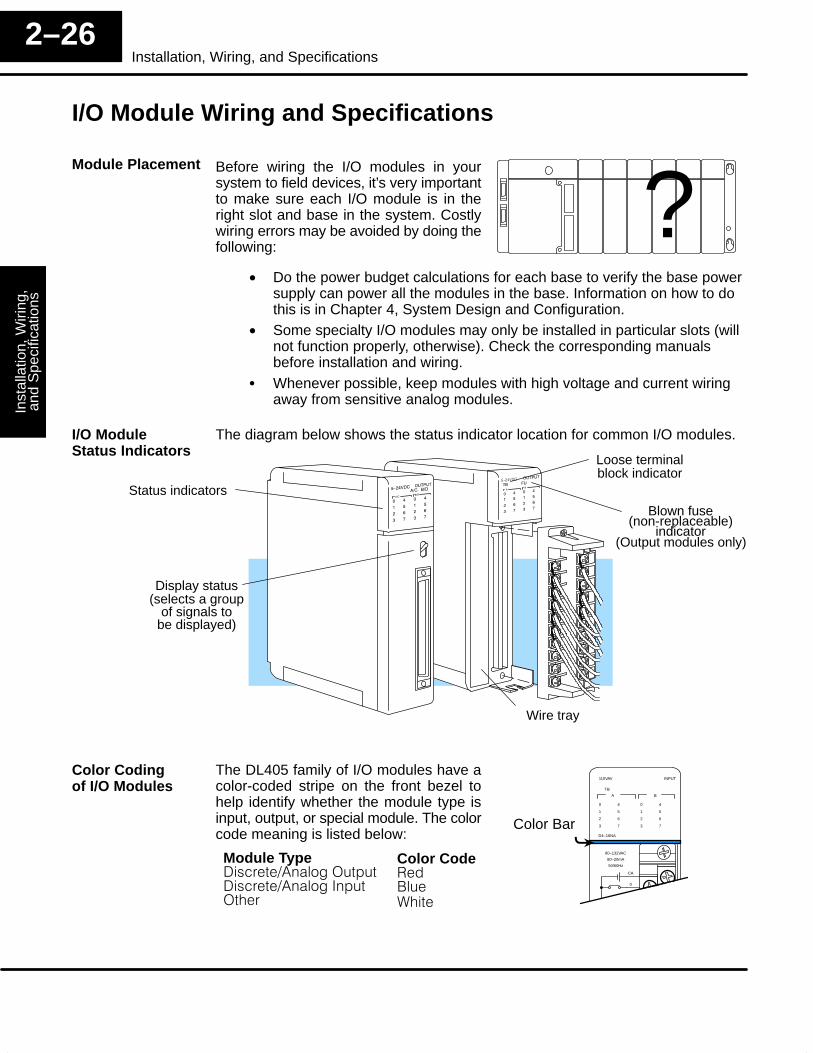
I/O Module Wiring and Specifications
Before wiring the I/O modules in yoursystem to field devices, it’s very importantto make sure each I/O module is in theright slot and base in the system. Costlywiring errors may be avoided by doing thefollowing:
?• Do the power budget calculations for each base to verify the base power
supply can power all the modules in the base. Information on how to dothis is in Chapter 4, System Design and Configuration.
• Some specialty I/O modules may only be installed in particular slots (willnot function properly, otherwise). Check the corresponding manualsbefore installation and wiring.
� Whenever possible, keep modules with high voltage and current wiringaway from sensitive analog modules.
The diagram below shows the status indicator location for common I/O modules.
Display status
Blown fuse(non-replaceable)
indicator
Loose terminalblock indicator
Status indicators
(selects a groupof signals to
be displayed)
Wire tray
(Output modules only)
The DL405 family of I/O modules have acolor-coded stripe on the front bezel tohelp identify whether the module type isinput, output, or special module. The colorcode meaning is listed below:
0
1
2
3
4
5
6
7
A
TB
110VAV
D4–16NA
0
1
2
3
4
5
6
7
B
INPUT
CA
0
80–132VAC
80–20mA
50/60Hz
Color Bar
Module Type���( ���&)�����'�������( ���&)���������'���
Color Code1������%����
�
Module Placement
I/O ModuleStatus Indicators
Color Codingof I/O Modules
Installation, Wiring,
and Specifications
Installation andS
afety Guidelines
2–27Installation , Wiring, and Specifications
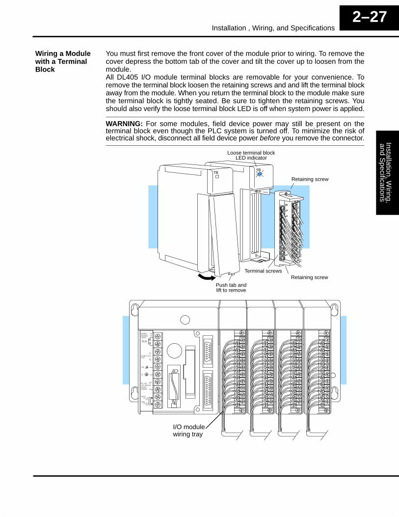
You must first remove the front cover of the module prior to wiring. To remove thecover depress the bottom tab of the cover and tilt the cover up to loosen from themodule.All DL405 I/O module terminal blocks are removable for your convenience. Toremove the terminal block loosen the retaining screws and and lift the terminal blockaway from the module. When you return the terminal block to the module make surethe terminal block is tightly seated. Be sure to tighten the retaining screws. Youshould also verify the loose terminal block LED is off when system power is applied.
WARNING: For some modules, field device power may still be present on theterminal block even though the PLC system is turned off. To minimize the risk ofelectrical shock, disconnect all field device power before you remove the connector.
Push tab andlift to remove
Retaining screwTerminal screws
Retaining screw
Loose terminal blockLED indicator
I/O modulewiring tray
Wiring a Modulewith a TerminalBlock
Inst
alla
tion,
Wiri
ng,
and
Spe
cific
atio
nsIn
stal
latio
n an
dS
afet
y G
uide
lines
2–28Installation, Wiring, and Specifications
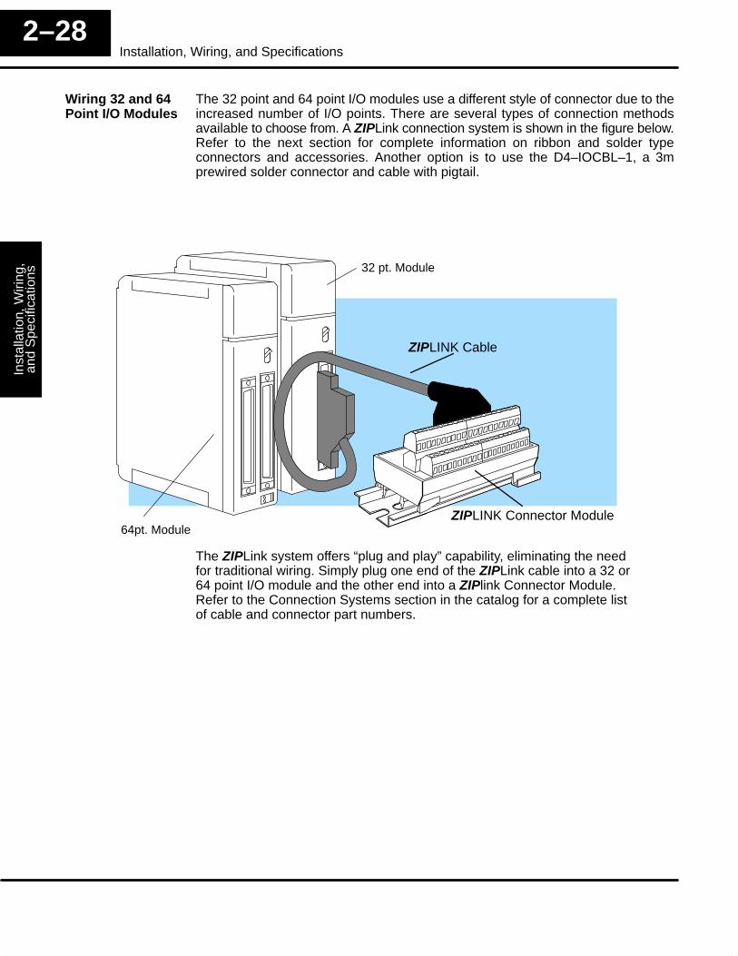
The 32 point and 64 point I/O modules use a different style of connector due to theincreased number of I/O points. There are several types of connection methodsavailable to choose from. A ZIPLink connection system is shown in the figure below.Refer to the next section for complete information on ribbon and solder typeconnectors and accessories. Another option is to use the D4–IOCBL–1, a 3mprewired solder connector and cable with pigtail.
32 pt. Module
64pt. Module
ZIPLINK Cable
ZIPLINK Connector Module
The ZIPLink system offers “plug and play” capability, eliminating the needfor traditional wiring. Simply plug one end of the ZIPLink cable into a 32 or64 point I/O module and the other end into a ZIPlink Connector Module.Refer to the Connection Systems section in the catalog for a complete listof cable and connector part numbers.
Wiring 32 and 64Point I/O Modules
Installation, Wiring,
and Specifications
Installation andS
afety Guidelines
2–29Installation , Wiring, and Specifications
Both types of connectors are available from PLCDirect. These same connectors arealso available from other Fujitsu Microelectronics, Inc. Use the following partnumbers to order these connectors.PLCDirect Part Numbers
� D4–IO3264R — Ribbon cable connectors, 2 in a pack. Can be used oneither 32 point or 64 point modules.
� D4–IO3264S — Solder type connector, 2 in a pack. Can be used oneither 32 point or 64 point modules.
Fujitsu Part NumbersFor connectors made by Fujitsu, you may contact Fijitsu at the following address:Fujitsu Microelectronics, Inc.Electronic Components Division3545 North First StreetSan Jose, CA 95134–1804 USA408–922–9000
• FCN–367J040–AU/F, or –AG/F — 32 / 64 point ribbon cable connector• FCN–361J040–AU, or –AG — 32 / 64 point solder type connector
(AU connectors use gold over palladium plating. AG connectors use silver plating.)
If you wish to use a terminal block with your 32 or 64 point module, here is a partial listof vendors who can provide the parts you will need to build the configuration shownearlier consisting of a ribbon cable, a ribbon cable connector and a terminal block.
Vendors
3M Electronic Products Division6801 River Place Blvd.Austin, TX 78726–9000800–225–5373
DuPont Connector SystemsBarley Mill PlazaWilmington, DE 19898–0019800–237–2374
Augat/RDI525 Randy Rd.Carol Stream, IL 60188708–682–4100
Phoenix Contacts ProductsP.O. Box 4100Harrisburg, PA 17111–0100717–944–1300
AMP IncorporatedP.O. Box 3608Harrisburg, PA 17105–3608717–564–0100
Thomas & Betts Electronics Div.200 Executive Center DriveGreenville, SC 29616803–676–2900
Cooper Industries, Belden Div.P.O. Box 1980Richmond, IN 47375317–983–5200
Weidmuller, Inc.821 Southlake Blvd.Richmond, VA 23236804–794–2877
Newark Electronics4108 North Ravenswood Ave.Chicago, Il 60640312–784–5100
(Newark Electronics is a distributorfor all of the above product manufac-turers except for Phoenix ContactsProducts)
Part Numbers forModuleConnectors
Vendors For theParts Used in theTerminal BlockConfiguration
Inst
alla
tion,
Wiri
ng,
and
Spe
cific
atio
nsIn
stal
latio
n an
dS
afet
y G
uide
lines
2–30Installation, Wiring, and Specifications
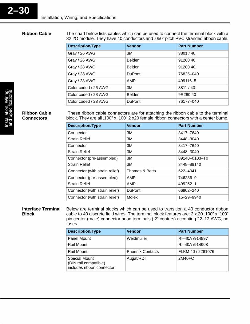
The chart below lists cables which can be used to connect the terminal block with a32 I/O module. They have 40 conductors and .050” pitch PVC stranded ribbon cable.
Description/Type Vendor Part Number
Gray / 26 AWG 3M 3801 / 40
Gray / 26 AWG Belden 9L260 40
Gray / 28 AWG Belden 9L280 40
Gray / 28 AWG DuPont 76825–040
Gray / 28 AWG AMP 499116–5
Color coded / 26 AWG 3M 3811 / 40
Color coded / 28 AWG Belden 9R280 40
Color coded / 28 AWG DuPont 76177–040
These ribbon cable connectors are for attaching the ribbon cable to the terminalblock. They are all .100” x .100” 2 x20 female ribbon connectors with a center bump.
Description/Type Vendor Part Number
Connector
Strain Relief
3M
3M
3417–7640
3448–3040
Connector
Strain Relief
3M
3M
3417–7640
3448–3040
Connector (pre-assembled) 3M 89140–0103–T0
Strain Relief 3M 3448–89140
Connector (with strain relief) Thomas & Betts 622–4041
Connector (pre-assembled) AMP 746286–9
Strain Relief AMP 499252–1
Connector (with strain relief) DuPont 66902–240
Connector (with strain relief) Molex 15–29–9940
Below are terminal blocks which can be used to transition a 40 conductor ribboncable to 40 discrete field wires. The terminal block features are: 2 x 20 .100” x .100”pin center (male) connector head terminals (.2” centers) accepting 22–12 AWG, nofuses.
Description/Type Vendor Part Number
Panel Mount Weidmuller RI–40A /914897
Rail Mount RI–40A /914908
Rail Mount Phoenix Contacts FLKM 40 / 2281076
Special Mount (DIN rail compatible) includes ribbon connector
Augat/RDI 2M40FC
Ribbon Cable
Ribbon CableConnectors
Interface TerminalBlock
Installation, Wiring,
and Specifications
Installation andS
afety Guidelines
2–31Installation , Wiring, and Specifications
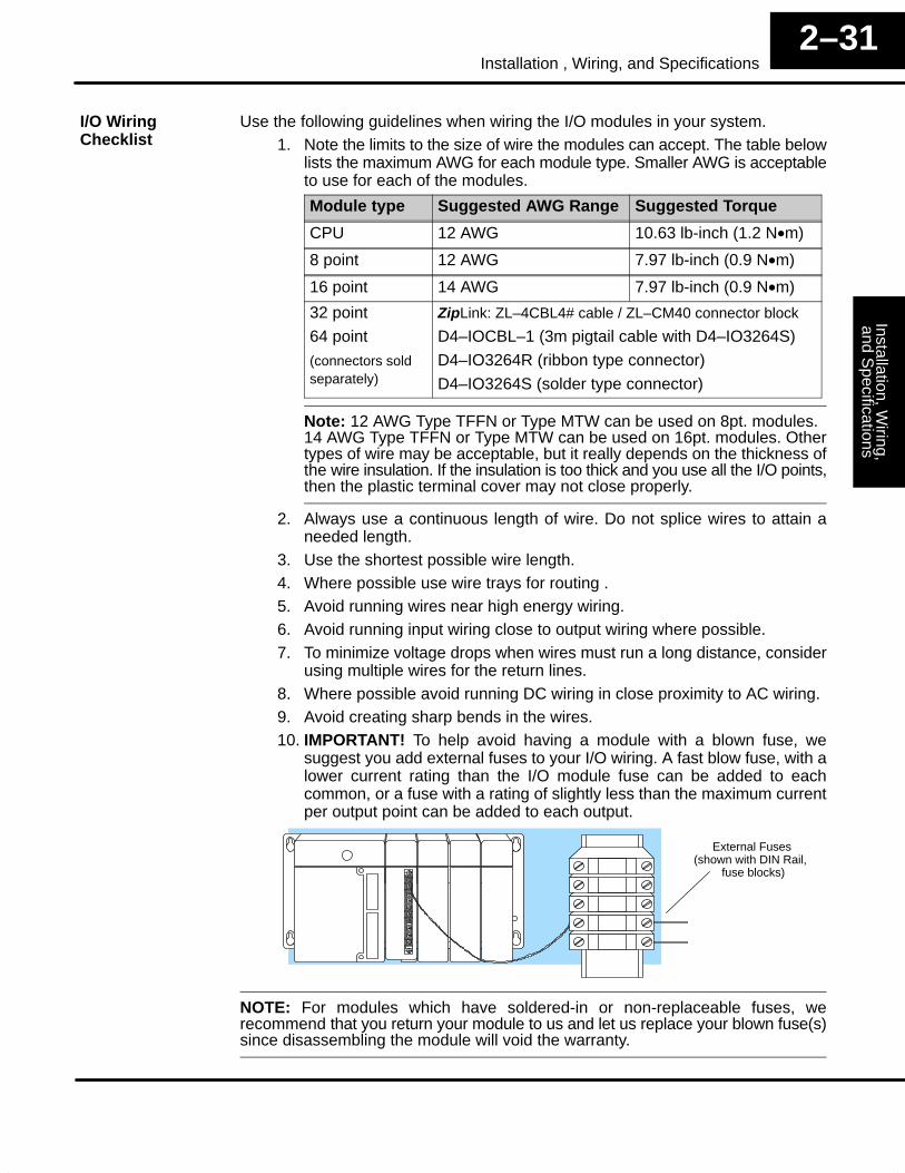
Use the following guidelines when wiring the I/O modules in your system.1. Note the limits to the size of wire the modules can accept. The table below
lists the maximum AWG for each module type. Smaller AWG is acceptableto use for each of the modules.
Module type Suggested AWG Range Suggested Torque
CPU 12 AWG 10.63 lb-inch (1.2 N•m)
8 point 12 AWG 7.97 lb-inch (0.9 N•m)
16 point 14 AWG 7.97 lb-inch (0.9 N•m)
32 point
64 point
(connectors soldseparately)
ZipLink: ZL–4CBL4# cable / ZL–CM40 connector block
D4–IOCBL–1 (3m pigtail cable with D4–IO3264S)
D4–IO3264R (ribbon type connector)
D4–IO3264S (solder type connector)
Note: 12 AWG Type TFFN or Type MTW can be used on 8pt. modules.14 AWG Type TFFN or Type MTW can be used on 16pt. modules. Othertypes of wire may be acceptable, but it really depends on the thickness ofthe wire insulation. If the insulation is too thick and you use all the I/O points,then the plastic terminal cover may not close properly.
2. Always use a continuous length of wire. Do not splice wires to attain aneeded length.
3. Use the shortest possible wire length.4. Where possible use wire trays for routing .5. Avoid running wires near high energy wiring.6. Avoid running input wiring close to output wiring where possible.7. To minimize voltage drops when wires must run a long distance, consider
using multiple wires for the return lines.8. Where possible avoid running DC wiring in close proximity to AC wiring.9. Avoid creating sharp bends in the wires.10. IMPORTANT! To help avoid having a module with a blown fuse, we
suggest you add external fuses to your I/O wiring. A fast blow fuse, with alower current rating than the I/O module fuse can be added to eachcommon, or a fuse with a rating of slightly less than the maximum currentper output point can be added to each output.
External Fuses(shown with DIN Rail,
fuse blocks)
NOTE: For modules which have soldered-in or non-replaceable fuses, werecommend that you return your module to us and let us replace your blown fuse(s)since disassembling the module will void the warranty.
I/O WiringChecklist
Inst
alla
tion,
Wiri
ng,
and
Spe
cific
atio
nsIn
stal
latio
n an
dS
afet
y G
uide
lines
2–32Installation, Wiring, and Specifications
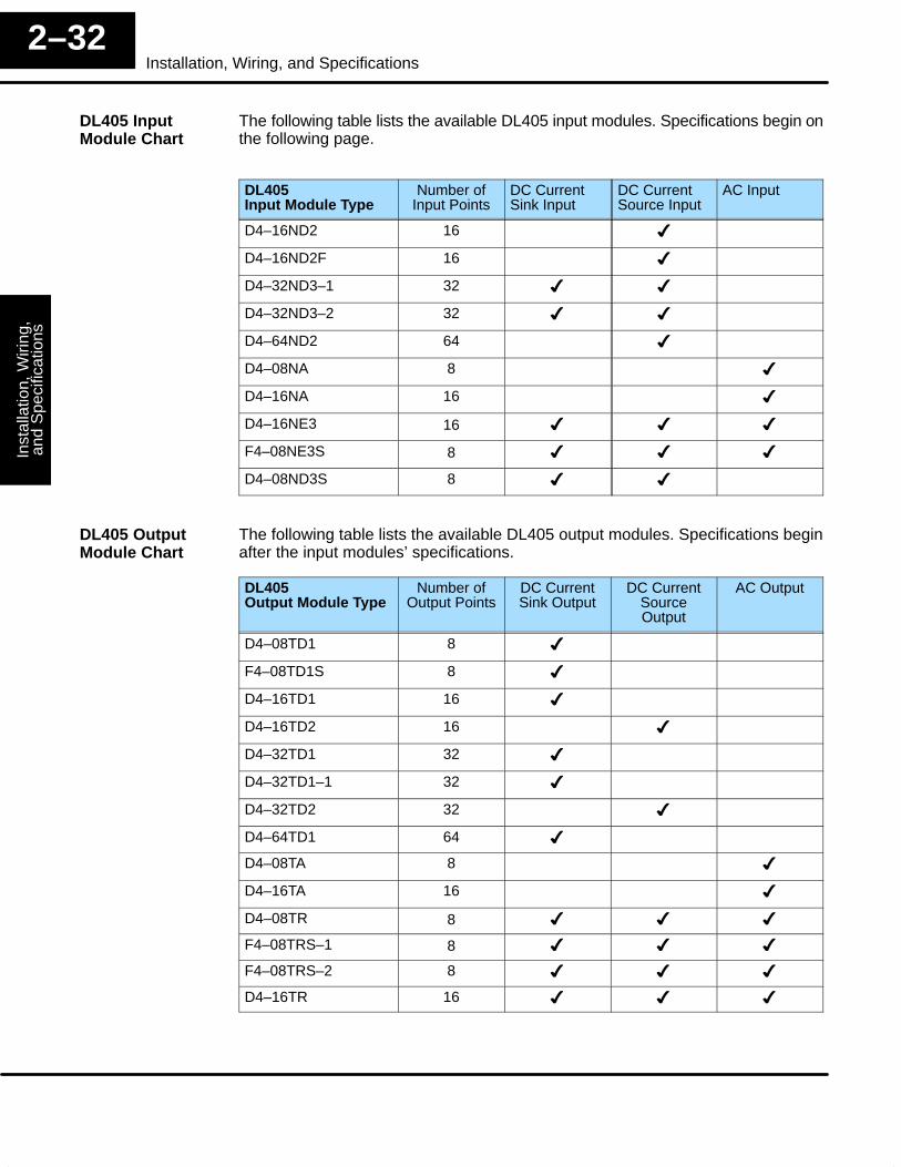
The following table lists the available DL405 input modules. Specifications begin onthe following page.
DL405Input Module Type
Number ofInput Points
DC CurrentSink Input
DC CurrentSource Input
AC Input
D4–16ND2 16 �
D4–16ND2F 16 �
D4–32ND3–1 32 � �
D4–32ND3–2 32 � �
D4–64ND2 64 �
D4–08NA 8 �
D4–16NA 16 �
D4–16NE3 16 � � �
F4–08NE3S 8 � � �
D4–08ND3S 8 � �
The following table lists the available DL405 output modules. Specifications beginafter the input modules’ specifications.
DL405 Output Module Type
Number ofOutput Points
DC CurrentSink Output
DC CurrentSourceOutput
AC Output
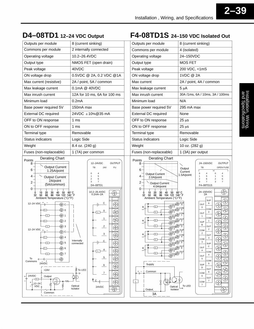
D4–08TD1 8 �
F4–08TD1S 8 �
D4–16TD1 16 �
D4–16TD2 16 �
D4–32TD1 32 �
D4–32TD1–1 32 �
D4–32TD2 32 �
D4–64TD1 64 �
D4–08TA 8 �
D4–16TA 16 �
D4–08TR 8 � � �
F4–08TRS–1 8 � � �
F4–08TRS–2 8 � � �
D4–16TR 16 � � �
DL405 InputModule Chart
DL405 OutputModule Chart
Installation, Wiring,
and Specifications
Installation andS
afety Guidelines
2–33Installation , Wiring, and Specifications
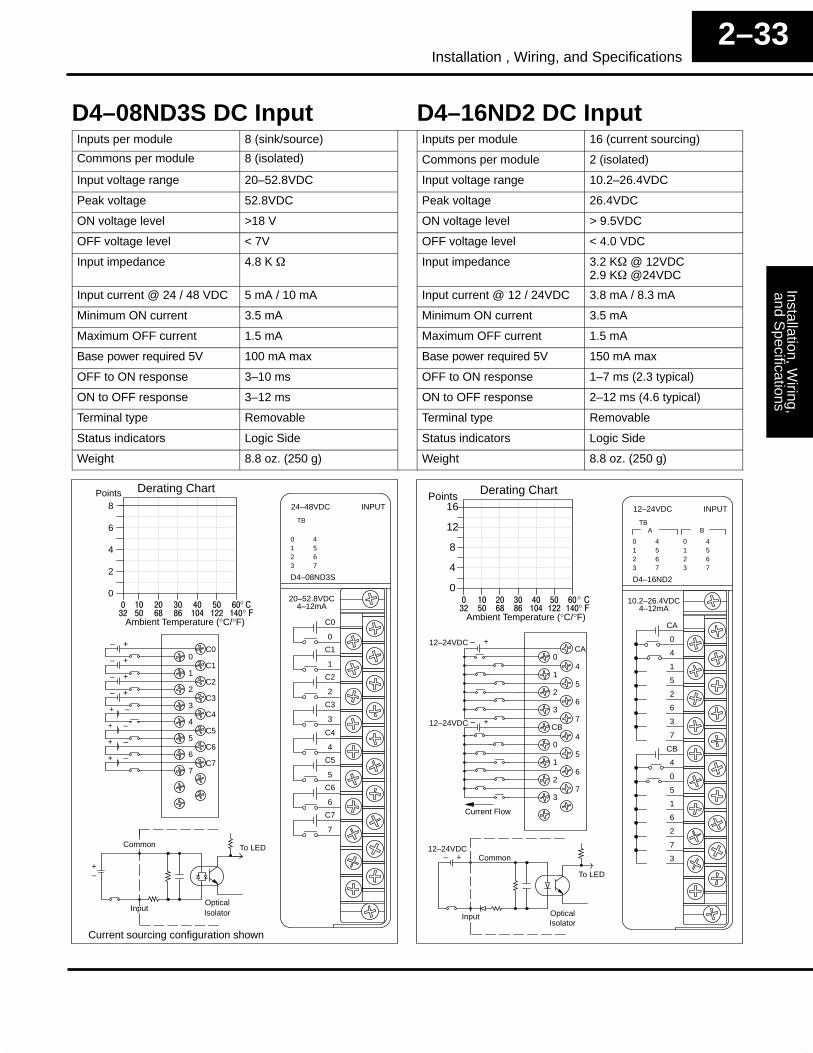
D4–08ND3S DC Input D4–16ND2 DC InputInputs per module 8 (sink/source) Inputs per module 16 (current sourcing)
Commons per module 8 (isolated) Commons per module 2 (isolated)
Input voltage range 20–52.8VDC Input voltage range 10.2–26.4VDC
Peak voltage 52.8VDC Peak voltage 26.4VDC
ON voltage level >18 V ON voltage level > 9.5VDC
OFF voltage level < 7V OFF voltage level < 4.0 VDC
Input impedance 4.8 K � Input impedance 3.2 K� @ 12VDC2.9 K� @24VDC
Input current @ 24 / 48 VDC 5 mA / 10 mA Input current @ 12 / 24VDC 3.8 mA / 8.3 mA
Minimum ON current 3.5 mA Minimum ON current 3.5 mA
Maximum OFF current 1.5 mA Maximum OFF current 1.5 mA
Base power required 5V 100 mA max Base power required 5V 150 mA max
OFF to ON response 3–10 ms OFF to ON response 1–7 ms (2.3 typical)
ON to OFF response 3–12 ms ON to OFF response 2–12 ms (4.6 typical)
Terminal type Removable Terminal type Removable
Status indicators Logic Side Status indicators Logic Side
Weight 8.8 oz. (250 g) Weight 8.8 oz. (250 g)
0123
4567
TB
24–48VDC
D4–08ND3S
INPUT
C0
0
20–52.8VDC4–12mA
C1
1
C2
2
C3
3
C4
4
C5
5
C6
6
C7
7
Derating Chart
0
2
4
6
8Points
� �� �� �� �� �� ��
Ambient Temperature (°C/°F)�� �� �� �� ��� ��� ���
°°
C00
C11
C22
C33
C44
C55
C66
C77
– +
– +
– +
– +
+ –
+ –
+ –
+ –
OpticalIsolator
Common
Input
+–
To LED
Current sourcing configuration shown
0123
4567
ATB
12–24VDC
D4–16ND2
0123
4567
B
INPUT
CA
0
4
1
5
2
6
3
7
CB
4
0
5
1
6
2
7
3
10.2–26.4VDC4–12mA
Derating Chart
0
4
8
12
16Points
� �� �� �� �� �� ��
Ambient Temperature (°C/°F)�� �� �� �� ��� ��� ���
°°
CA0
41
52
63
7CB
40
51
62
73
– +
– +12–24VDC
12–24VDC
Current Flow
Optical
Common
Isolator
– +12–24VDC
To LED
Input
Inst
alla
tion,
Wiri
ng,
and
Spe
cific
atio
nsIn
stal
latio
n an
dS
afet
y G
uide
lines
2–34Installation, Wiring, and Specifications
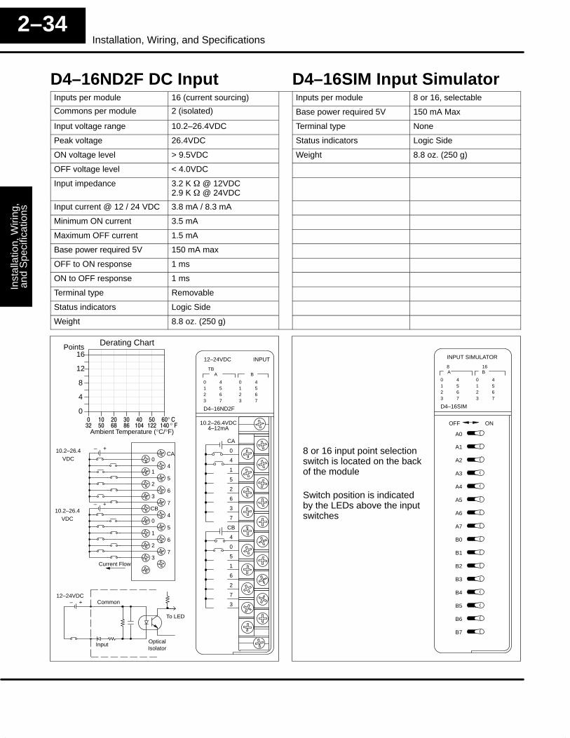
D4–16ND2F DC Input D4–16SIM Input SimulatorInputs per module 16 (current sourcing) Inputs per module 8 or 16, selectable
Commons per module 2 (isolated) Base power required 5V 150 mA Max
Input voltage range 10.2–26.4VDC Terminal type None
Peak voltage 26.4VDC Status indicators Logic Side
ON voltage level > 9.5VDC Weight 8.8 oz. (250 g)
OFF voltage level < 4.0VDC
Input impedance 3.2 K � @ 12VDC2.9 K � @ 24VDC
Input current @ 12 / 24 VDC 3.8 mA / 8.3 mA
Minimum ON current 3.5 mA
Maximum OFF current 1.5 mA
Base power required 5V 150 mA max
OFF to ON response 1 ms
ON to OFF response 1 ms
Terminal type Removable
Status indicators Logic Side
Weight 8.8 oz. (250 g)
0123
4567
ATB
12–24VDC
D4–16ND2F
0123
4567
B
INPUT
CA
0
4
1
5
2
6
3
7
CB
4
0
5
1
6
2
7
3
10.2–26.4VDC4–12mA
CA0
41
52
63
7CB
40
51
62
73
– +
– +10.2–26.4
VDC
Current Flow
Derating Chart
0
4
8
12
16Points
� �� �� �� �� �� ��
Ambient Temperature (°C/°F)�� �� �� �� ��� ��� ���
°°
Optical
Common
Isolator
– +12–24VDC
To LED
Input
0123
4567
A8 16
INPUT SIMULATOR
D4–16SIM
0123
4567
B
A0
A1
A2
A3
A4
A5
A6
A7
B0
B1
B2
B3
B4
B5
B6
B7
OFF ON
8 or 16 input point selectionswitch is located on the backof the module
Switch position is indicatedby the LEDs above the inputswitches
10.2–26.4VDC

Installation, Wiring,
and Specifications
Installation andS
afety Guidelines
2–35Installation , Wiring, and Specifications
D4–32ND3–1, 24VDC Input D4–32ND3–2 5–12VDC InputInputs per module 32 (sink/source) Inputs per module 32 (sink/source)
Commons per module 4 (isolated) Commons per module 4 (isolated)
Input voltage range 20–28VDC Input voltage range 4.75–13.2VDC (TTL, CMOS)
Peak voltage 30VDC Peak voltage 15VDC
ON voltage level > 19V ON voltage level > 4 V (use pullup R for TTL in)
OFF voltage level < 10 V OFF voltage level < 2 V
Input impedance 4.8 K � Input impedance 2 K� @ 5V,1.6 K� @ 12V
Input current 5 mA Input current 3.1 mA @ 5V, 7.5 mA @ 12V
Minimum ON current 3.5 mA Minimum ON current 1.8 mA
Maximum OFF current 1.6 mA Maximum OFF current 0.8 mA
Base power required 5V 150 mA max Base power required 5V 150 mA max
OFF to ON response 2–10 ms OFF to ON response 1–4 ms
ON to OFF response 2–10 ms ON to OFF response 1–4 ms
Terminal type Removable, 40 pin conn. Terminal type Removable, 40 pin conn.
Status indicators Logic Side Status indicators Logic Side
Weight 6.6 oz. (190 g) Weight 6.6 oz. (190 g)
0123
4567
A/CA-B C-D
24VDC
D4–32ND3–1
0123
4567
B/D
INPUT
A4A0
A5A1
A6A2
A7A3
CICI
B4B0
B5B1
B6B2
B7B3
CIICII
C4C0
C5C1
C6C2
C7C3
CIIICIII
D4D0
D5D1
D6D2
D7D3
CIVCIV
DISPLAYSELECT A - B
C - D
4.2–5.8mA20–28VDC, CLASS2
A4A0
A5A1
A6A2
A7A3
COM I
B4B0
B5B1
B6B2
B7B3
COM II
C4C0
C5C1
C6C2
C7C3
COM III
D4D0
D5D1
D6D2
D7D3
COM IV
Current Flow
+
–User
Supply
+
–UserSupply
Current Flow
+
–User
Supply
Current Flow
Current Flow
Derating Chart
048121620242832
Points
� �� �� �� �� �� ��
Ambient Temperature (°C/°F)�� �� �� �� ��� ��� ���
°°
Optical
Common
Isolator
+ –24 VDC
To LED
InputCurrent sinking config. shown
Use Display Select switch to view(A0–A7, B0–B7) or (C0–C7, D0–D7)
0123
4567
A/CA-B C-D
5–12VDC
D4–32ND3–2
0123
4567
B/D
INPUT
A4A0
A5A1
A6A2
A7A3
CICI
B4B0
B5B1
B6B2
B7B3
CIICII
C4C0
C5C1
C6C2
C7C3
CIIICIII
D4D0
D5D1
D6D2
D7D3
CIVCIV
DISPLAYSELECT
4.75–13.2VDC, CLASS23.1–8.2mA
A - B
C - D
Derating Chart
048121620242832
Points
A4A0
A5A1
A6A2
A7A3
COM I
B4B0
B5B1
B6B2
B7B3
COM II
C4C0
C5C1
C6C2
C7C3
COM III
D4D0
D5D1
D6D2
D7D3
COM IV
Current Flow
+
–User
Supply
+
–User
Supply
Current Flow
+
–User
Supply
Current Flow
Current Flow
Optical
Common
Isolator
+ –5–12 VDC
To LED
Input Current sinking config. shown
Use Display Select switch to view(A0–A7, B0–B7) or (C0–C7, D0–D7)
� �� �� �� �� �� ��
Ambient Temperature (°C/°F)�� �� �� �� ��� ��� ���
°°
Inst
alla
tion,
Wiri
ng,
and
Spe
cific
atio
nsIn
stal
latio
n an
dS
afet
y G
uide
lines
2–36Installation, Wiring, and Specifications
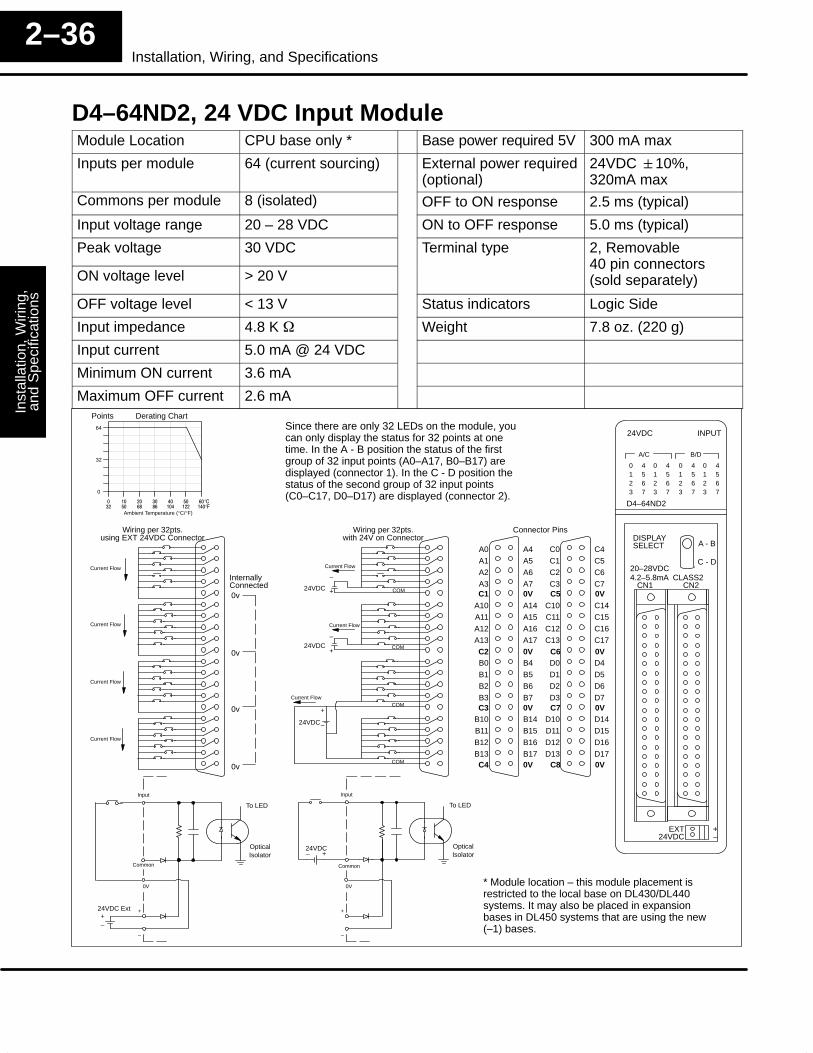
D4–64ND2, 24 VDC Input ModuleModule Location CPU base only * Base power required 5V 300 mA max
Inputs per module 64 (current sourcing) External power required(optional)
24VDC �10%,320mA max
Commons per module 8 (isolated) OFF to ON response 2.5 ms (typical)
Input voltage range 20 – 28 VDC ON to OFF response 5.0 ms (typical)
Peak voltage 30 VDC Terminal type 2, Removable
ON voltage level > 20 V40 pin connectors(sold separately)
OFF voltage level < 13 V Status indicators Logic Side
Input impedance 4.8 K � Weight 7.8 oz. (220 g)
Input current 5.0 mA @ 24 VDC
Minimum ON current 3.6 mA
Maximum OFF current 2.6 mA
COM
COM
COM
COM
Current Flow
+
–
24VDC
+
–24VDC
+
–24VDC
Current Flow
Current Flow
0123
4567
A/C
24VDC
D4–64ND2
B/D
INPUT
Derating Chart
0
32
64
Points
DISPLAYSELECT
4.2–5.8mA CLASS2CN1
Optical
Common
Isolator– +24VDC
� �� �� �� �� �� ��
Ambient Temperature (°C/°F)�� �� �� �� ��� ��� ���
°°
To LED
A - B
C - D
Input
Since there are only 32 LEDs on the module, youcan only display the status for 32 points at onetime. In the A - B position the status of the firstgroup of 32 input points (A0–A17, B0–B17) aredisplayed (connector 1). In the C - D position thestatus of the second group of 32 input points(C0–C17, D0–D17) are displayed (connector 2).
0123
4567
0123
4567
0123
4567
20–28VDC
CN2
EXT24VDC
+–
Wiring per 32pts.with 24V on Connector
OpticalIsolator
To LED
Input
+–
–
+24VDC Ext
0V
Wiring per 32pts.using EXT 24VDC Connector
A1
A0
A3
A2Current Flow
Current Flow
Current Flow
Current Flow
A5
A4
A7
A6
A11
A10
A13
A12
A15
A14
A17
A16
B1
B0
B3
B2
B5
B4
B7
B6
B11
B10
B13
B12
B15
B14
B17
B16
C1
C0
C3
C2
C5
C4
C7
C6
C11
C10
C13
C12
C15
C14
C17
C16
D1
D0
D3
D2
D5
D4
D7
D6
D11
D10
D13
D12
D15
D14
D17
D16
0v
0v
0v
0v
InternallyConnected
Common
Connector Pins
C1 0V
C2 0V
C3 0V
C4 0V
C5 0V
C6 0V
C7 0V
C8 0V
–
+
0V * Module location – this module placement isrestricted to the local base on DL430/DL440systems. It may also be placed in expansionbases in DL450 systems that are using the new(–1) bases.
Installation, Wiring,
and Specifications
Installation andS
afety Guidelines
2–37Installation , Wiring, and Specifications
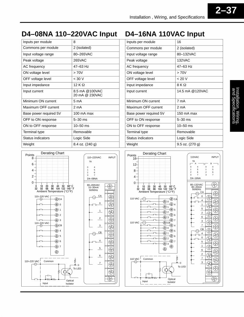
D4–08NA 110–220VAC Input D4–16NA 110VAC InputInputs per module 8 Inputs per module 16
Commons per module 2 (isolated) Commons per module 2 (isolated)
Input voltage range 80–265VAC Input voltage range 80–132VAC
Peak voltage 265VAC Peak voltage 132VAC
AC frequency 47–63 Hz AC frequency 47–63 Hz
ON voltage level > 70V ON voltage level > 70V
OFF voltage level < 30 V OFF voltage level < 20 V
Input impedance 12 K � Input impedance 8 K �
Input current 8.5 mA @100VAC20 mA @ 230VAC
Input current 14.5 mA @120VAC
Minimum ON current 5 mA Minimum ON current 7 mA
Maximum OFF current 2 mA Maximum OFF current 2 mA
Base power required 5V 100 mA max Base power required 5V 150 mA max
OFF to ON response 5–30 ms OFF to ON response 5–30 ms
ON to OFF response 10–50 ms ON to OFF response 10–50 ms
Terminal type Removable Terminal type Removable
Status indicators Logic Side Status indicators Logic Side
Weight 8.4 oz. (240 g) Weight 9.5 oz. (270 g)
0123
4567
TB
110–220VAC
D4–08NA
INPUT
CA
0
1
2
3
CB
4
5
6
7
80–265VAC10–30mA50/60Hz
CA
0
1
2
3
CB
4
5
6
7
110–220 VAC
110–220 VAC
OpticalIsolator
Common
To LED
Input
110–220 VAC
0123
4567
ATB
110VAC
D4–16NA
0123
4567
B
INPUT
CA
0
4
1
5
2
6
3
7
CB
4
0
5
1
6
2
7
3
80–132VAC80–20mA50/60Hz
Derating Chart
0
4
8
12
16Points
� �� �� �� �� �� ��
Ambient Temperature (°C/°F)�� �� �� �� ��� ��� ���
°°
CA0
41
52
63
7CB
40
51
62
73
110 VAC
110 VAC
OpticalIsolator
Common
To LED
Input
110 VAC
Derating Chart
0
2
4
6
8Points
� �� �� �� �� �� ��
Ambient Temperature (°C/°F)�� �� �� �� ��� ��� ���
°°

Inst
alla
tion,
Wiri
ng,
and
Spe
cific
atio
nsIn
stal
latio
n an
dS
afet
y G
uide
lines
2–38Installation, Wiring, and Specifications
D4-16NE3 12–24VAC/DC Input F4-08NE3S 90–150VAC/DC InInputs per module 16 (sink/source) Inputs per module 8 (sink/source)
Commons per module 2 (isolated) Commons per module 8 (isolated)
Input voltage range 10.2–26.4VAC/VDC Input voltage range 90–150 VAC/VDC
Peak voltage 37.5VAC/VDC Peak voltage 350 peak < 1ms
AC frequency 47–63 Hz AC frequency 47–63 Hz
ON voltage level > 9.5V ON voltage level > 90 VDC / 75VAC
OFF voltage level < 3.0V OFF voltage level < 60 VDC / 45VAC
Input impedance @ 12V/24V 3.2 K � / 2.9 K � Input impedance 22 K �
Input current @ 12V / 24V 3.8 mA / 8.3 mA Input current 5.5 mA @ 120V
Minimum ON current 4 mA Minimum ON current 4 mA
Maximum OFF current 1.5 mA Maximum OFF current 2 mA
Base power required 5V 150 mA max Base power required 5V 90 mA max
OFF to ON response 5–40 ms OFF to ON response 8 ms
ON to OFF response 10–50 ms ON to OFF response 15 ms
Terminal type Removable Terminal type Removable
Status indicators Logic Side Status indicators Logic Side
Weight 8.8 oz. (250 g) Weight 9 oz. (256 g)
Derating Chart
0
4
8
12
16Points
� �� �� �� �� �� ��
Ambient Temperature (°C/°F)�� �� �� �� ��� ��� ���
°°
0123
4567
ATB
12–24VAC/DC
D4–16NE3
0123
4567
B
INPUT
CA
0
4
1
5
2
6
3
7
CB
4
0
5
1
6
2
7
3
10.2–26.4V
4–18mA50/60 Hz/DC
AC/DC
CA0
41
52
63
7CB
40
51
62
73
Common
Current sourcing configuration shown
+To LED
OpticalIsolator
–
Input
TB
90–150VAC/DC
F4–08NE3S
INPUT
90–150VDC90–150VAC
0123
4567
IN0
IN0
IN2
IN2
IN4
IN4
IN6
IN6
IN1
IN1
IN3
IN3
IN5
IN5
IN7
IN7
Derating Chart
0
2
4
6
8Points
� �� �� �� �� �� ��
Ambient Temperature (°C/°F)�� �� �� �� ��� ��� ���
°°
IN0
IN0
IN2
IN2
IN4
IN4
IN6
IN6
IN1
IN1
IN3
IN3
IN5
IN5
IN7
IN7
+
To LED
OpticalIsolator
–
Common
Input
Installation, Wiring,
and Specifications
Installation andS
afety Guidelines
2–39Installation , Wiring, and Specifications
D4–08TD1 12–24 VDC Output F4-08TD1S 24–150 VDC Isolated OutOutputs per module 8 (current sinking) Outputs per module 8 (current sinking)
Commons per module 2 internally connected Commons per module 4 (isolated)
Operating voltage 10.2–26.4VDC Operating voltage 24–150VDC
Output type NMOS FET (open drain) Output type MOS FET
Peak voltage 40VDC Peak voltage 200 VDC, <1mS
ON voltage drop 0.5VDC @ 2A, 0.2 VDC @1A ON voltage drop 1VDC @ 2A
Max current (resistive) 2A / point, 5A / common Max current 2A / point, 4A / common
Max leakage current 0.1mA @ 40VDC Max leakage current 5 �A
Max inrush current 12A for 10 ms, 6A for 100 ms Max inrush current 30A /1ms, 6A / 10ms, 3A / 100ms
Minimum load 0.2mA Minimum load N/A
Base power required 5V 150mA max Base power required 5V 295 mA max
External DC required 24VDC �10%@35 mA External DC required None
OFF to ON response 1 ms OFF to ON response 25 �s
ON to OFF response 1 ms ON to OFF response 25 �s
Terminal type Removable Terminal type Removable
Status indicators Logic Side Status indicators Logic Side
Weight 8.4 oz. (240 g) Weight 10 oz. (282 g)
Fuses (non-replaceable) 1 (7A) per common Fuses (non-replaceable) 1 (3A) per output
0123
4567
TB FU
12–24VDC
D4–08TD1
OUTPUT
C
0
1
2
3
C
4
5
6
7
10.2–26.4VDC0.2mA–2A
L
L
24VDC
24V
C
Derating Chart
0
2
4
6
8Points
� �� �� �� �� �� ��
Ambient Temperature (°C/°F)�� �� �� �� ��� ��� ���
°°
Output Current1.25A/point
Output Current2A/point
(5A/common)
C
0
1
2
3
C
4
5
6
7
+ –
L
L
L
L
+ –
L
L
L
L
24VDC– +
To Commons
12–24 VDC
12–24 VDC
Common
L
12–24+
–
+
–
24VDC
VDC
To LED
OpticalIsolator
+24V
Output
Internally connected
TB OPEN FUSE
24–150VDC
F4–08TD1S
OUTPUT
24–150VDC2A
0123
4567
0123
4567
SUPA
COM0
COM1
OUT2
OUT3
SUPC
COM4
COM5
OUT6
OUT7
OUT0
OUT1
SUPB
COM2
COM3
OUT4
OUT5
SUPD
COM6
COM7
Derating Chart
0
2
4
6
8Points
� �� �� �� �� �� ��
Ambient Temperature (°C/°F)�� �� �� �� ��� ��� ���
°°
Output Current
1.5A/pointOutput Current2.0A/point
Output Current4.0A/point
L
L
L
L
L
L
L
L
–+
–+
–+
–+
OUT0
OUT1
SUPA
COM0
COM1SUP
B
COM2
COM3
OUT4
OUT5
SUPD
COM6
COM7
OUT2
OUT3
SUPC
COM4
COM5
OUT6
OUT7
OpticalIsolator
+ –
L
To LED
3A
Supply
Common
Output
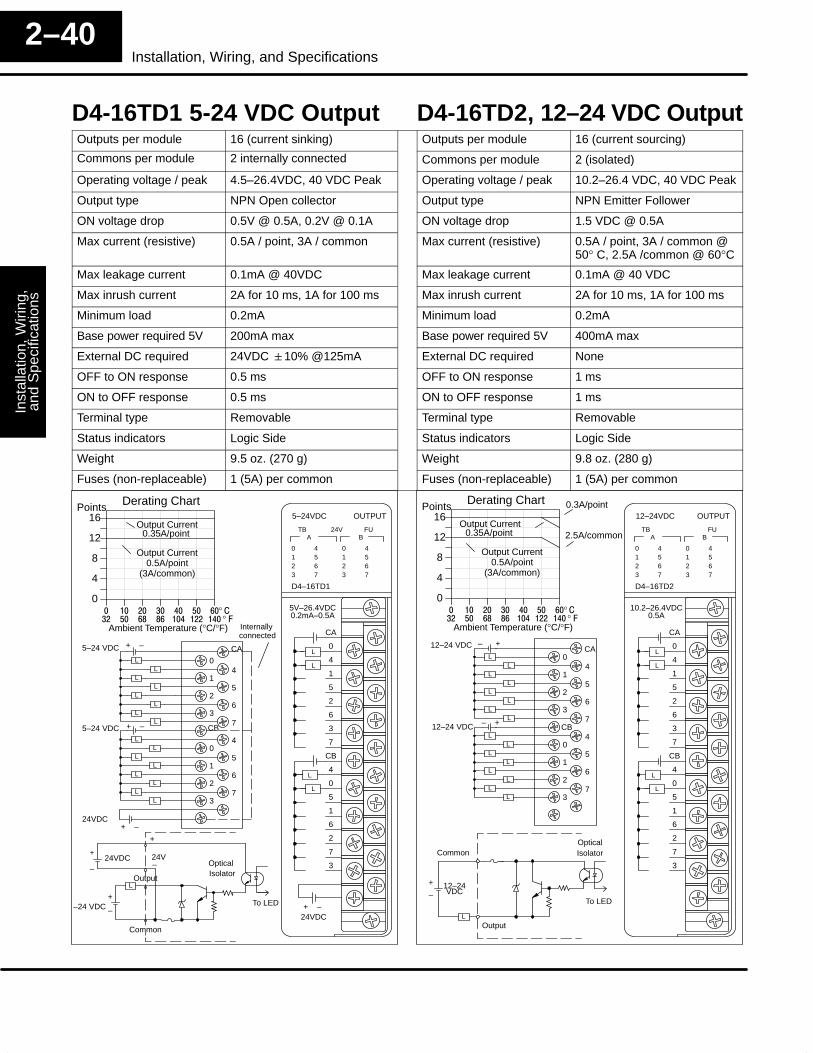
Inst
alla
tion,
Wiri
ng,
and
Spe
cific
atio
nsIn
stal
latio
n an
dS
afet
y G
uide
lines
2–40Installation, Wiring, and Specifications
D4-16TD1 5-24 VDC Output D4-16TD2, 12–24 VDC OutputOutputs per module 16 (current sinking) Outputs per module 16 (current sourcing)
Commons per module 2 internally connected Commons per module 2 (isolated)
Operating voltage / peak 4.5–26.4VDC, 40 VDC Peak Operating voltage / peak 10.2–26.4 VDC, 40 VDC Peak
Output type NPN Open collector Output type NPN Emitter Follower
ON voltage drop 0.5V @ 0.5A, 0.2V @ 0.1A ON voltage drop 1.5 VDC @ 0.5A
Max current (resistive) 0.5A / point, 3A / common Max current (resistive) 0.5A / point, 3A / common @50° C, 2.5A /common @ 60°C
Max leakage current 0.1mA @ 40VDC Max leakage current 0.1mA @ 40 VDC
Max inrush current 2A for 10 ms, 1A for 100 ms Max inrush current 2A for 10 ms, 1A for 100 ms
Minimum load 0.2mA Minimum load 0.2mA
Base power required 5V 200mA max Base power required 5V 400mA max
External DC required 24VDC �10% @125mA External DC required None
OFF to ON response 0.5 ms OFF to ON response 1 ms
ON to OFF response 0.5 ms ON to OFF response 1 ms
Terminal type Removable Terminal type Removable
Status indicators Logic Side Status indicators Logic Side
Weight 9.5 oz. (270 g) Weight 9.8 oz. (280 g)
Fuses (non-replaceable) 1 (5A) per common Fuses (non-replaceable) 1 (5A) per common
0123
4567
ATB FU
5–24VDC
D4–16TD1
0123
4567
B
OUTPUT
CA
0
4
1
5
2
6
3
7
CB
4
0
5
1
6
2
7
3
5V–26.4VDC0.2mA–0.5A
L
L
L
L
24VDC+ –
24V
CA
04
15
26
37
CB
40
51
62
73
+ –
LL
LL
LL
LL
LL
LL
LL
LL
+ –
24VDC+ –
Internally connected
5–24 VDC
5–24 VDC
Derating Chart
0
4
8
12
16Points
� �� �� �� �� �� ��
Ambient Temperature (°C/°F)�� �� �� �� ��� ��� ���
°°
Output Current0.35A/point
Output Current0.5A/point
(3A/common)
Common
L
+
–
+
–24VDC
To LED
OpticalIsolator
Output
–
+
24V
–24 VDC
0123
4567
ATB FU
12–24VDC
D4–16TD2
0123
4567
B
OUTPUT
CA
0
4
1
5
2
6
3
7
CB
4
0
5
1
6
2
7
3
10.2–26.4VDC0.5A
L
L
L
L
CA0
41
52
63
7CB
40
51
62
73
– +
LL
LL
LL
LL
LL
LL
LL
LL
– +12–24 VDC
12–24 VDC
Derating Chart
0
4
8
12
16Points
� �� �� �� �� �� ��
Ambient Temperature (°C/°F)�� �� �� �� ��� ��� ���
°°
Output Current0.35A/point
Output Current0.5A/point
(3A/common)
2.5A/common
0.3A/point
Common
L
12–24+
– VDCTo LED
OpticalIsolator
Output
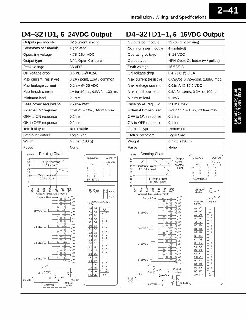
Installation, Wiring,
and Specifications
Installation andS
afety Guidelines
2–41Installation , Wiring, and Specifications
D4–32TD1, 5–24VDC Output D4–32TD1–1, 5–15VDC OutputOutputs per module 32 (current sinking) Outputs per module 32 (current sinking)
Commons per module 4 (isolated) Commons per module 4 (isolated)
Operating voltage 4.75–26.4 VDC Operating voltage 5–15 VDC
Output type NPN Open Collector Output type NPN Open Collector (w / pullup)
Peak voltage 36 VDC Peak voltage 16.5 VDC
ON voltage drop 0.6 VDC @ 0.2A ON voltage drop 0.4 VDC @ 0.1A
Max current (resistive) 0.2A / point, 1.6A / common Max current (resistive) 0.09A/pt, 0.72A/com, 2.88A/ mod.
Max leakage current 0.1mA @ 36 VDC Max leakage current 0.01mA @ 16.5 VDC
Max inrush current 1A for 10 ms, 0.5A for 100 ms Max inrush current 0.5A for 10ms, 0.2A for 100ms
Minimum load 0.1mA Minimum load 0.1mA
Base power required 5V 250mA max Base power req., 5V 250mA max
External DC required 24VDC �10%, 140mA max External DC required 5–15VDC �10%, 700mA max
OFF to ON response 0.1 ms OFF to ON response 0.1 ms
ON to OFF response 0.1 ms ON to OFF response 0.1 ms
Terminal type Removable Terminal type Removable
Status indicators Logic Side Status indicators Logic Side
Weight 6.7 oz. (190 g) Weight 6.7 oz. (190 g)
Fuses None Fuses None
0123
4567
A/CA-B C-D
5–24VDC
D4–32TD1
0123
4567
B/D
OUTPUT
A4A0
A5A1
A6A2
A7A3
VICI
B4B0
B5B1
B6B2
B7B3
VIICII
C4C0
C5C1
C6C2
C7C3
VIIICIII
D4D0
D5D1
D6D2
D7D3
VIVCIV
DISPLAYSELECT A - B
C - D
5–26VDC,CLASS 20.2A
Derating Chart
048
121620242832
Points
� �� �� �� �� �� ��
Ambient Temperature (°C/°F)�� �� �� �� ��� ��� ���
°°
Output current0.1A / point
Output current0.2A / point
L
+–24 VDC
Common
Output
OpticalIsolator
To LED
V+
A4A0
A5A1
A6A2
A7A3
V ICOM I
B4B0
B5B1
B6B2
B7B3
V IICOM II
C4C0
C5C1
C6C2
C7C3
V IIICOM III
D4D0
D5D1
D6D2
D7D3
V IVCOM IV
Current Flow
+
–24VDC
LL
LL
LL
LL
LL
LL
LL
LL
LL
LL
LL
LL
LL
LL
LL
LL
24 VDC
24 VDC
24 VDC
+
–
+
–
+
–
0123
4567
A/CA-B C-D
5–15VDC
D4–32TD1–1
0123
4567
B/D
OUTPUT
A4A0
A5A1
A6A2
A7A3
VICI
B4B0
B5B1
B6B2
B7B3
VIICII
C4C0
C5C1
C6C2
C7C3
VIIICIII
D4D0
D5D1
D6D2
D7D3
VIVCIV
DISPLAYSELECT A - B
C - D
5–15VDC, CLASS 20.09A
5–15VDC
5–15VDC
5–15VDC
5–15VDC
A4A0
A5A1
A6A2
A7A3
V ICOM I
B4B0
B5B1
B6B2
B7B3
V IICOM II
C4C0
C5C1
C6C2
C7C3
V IIICOM III
D4D0
D5D1
D6D2
D7D3
V IVCOM IV
Current Flow
+
–
LL
LL
LL
LL
LL
LL
LL
LL
LL
LL
LL
LL
LL
LL
LL
LL
+
–
+
–
+
–
Derating Chart
048
121620242832
Points
� �� �� �� �� �� ��
Ambient Temperature (°C/°F)�� �� �� �� ��� ��� ���
°°
Output current0.015A / point
Output current0.09A / point
Outputcurrent0.06A /point
L
+
–5–15VDC
Common
OutOpticalIsolator
To LED
V+
1.5K
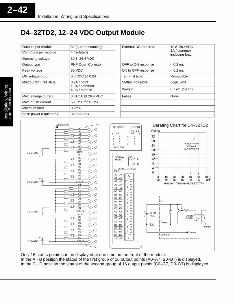
Inst
alla
tion,
Wiri
ng,
and
Spe
cific
atio
nsIn
stal
latio
n an
dS
afet
y G
uide
lines
2–42Installation, Wiring, and Specifications
D4–32TD2, 12–24 VDC Output Module
Outputs per module 32 (current sourcing) External DC required 10.8–26.4VDC
Commons per module 4 (isolated) 1A / common including load
Operating voltage 10.8–26.4 VDCincluding load
Output type PNP Open Collector OFF to ON response < 0.2 ms
Peak voltage 30 VDC ON to OFF response < 0.2 ms
ON voltage drop 0.6 VDC @ 0.2A Terminal type Removable
Max current (resistive) 0.2A / point Status indicators Logic Side1.0A / common4.0A / module Weight 6.7 oz. (190 g)
Max leakage current 0.01mA @ 26.4 VDC Fuses None
Max inrush current 500 mA for 10 ms
Minimum load 0.2mA
Base power required 5V 350mA max
0123
4567
A/CA-B C-D
12–24VDC
D4–32TD2
0123
4567
B/D
OUTPUT Derating Chart for D4–32TD2
0
4
8
12
16
20
24
28
32
Points
Output current 0.2 A /pt
(1A /common)
A4A0
A5A1
A6A2
A7A3
VICI
B4B0
B5B1
B6B2
B7B3
VIICII
C4C0
C5C1
C6C2
C7C3
VIIICIII
D4D0
D5D1
D6D2
D7D3
VIVCIV
DISPLAYSELECT A - B
C - D
11–26VDC, CLASS20.2A
A4A0
A5A1
A6A2
A7A3
V ICOM I
B4B0
B5B1
B6B2
B7B3
V IICOM II
C4C0
C5C1
C6C2
C7C3
V IIICOM III
D4D0
D5D1
D6D2
D7D3
V IVCOM IV
Current Flow
–
+
–
+
12–24VDC
L
L
L
L
L
L
L
L
L
L
L
L
L
L
L
L
–
+
–
+
L
L
L
L
L
L
L
L
L
L
L
L
L
L
L
L
12–24VDC
12–24VDC
12–24VDC
� �� �� �� �� �� ��
Ambient Temperature (°C/°F)�� �� �� �� ��� ��� ���
°°
L
+
–12–24VDC
Common
Output
OpticalIsolator
To LED
V+
Only 16 status points can be displayed at one time on the front of the module.In the A - B position the status of the first group of 16 output points (A0–A7, B0–B7) is displayed.In the C - D position the status of the second group of 16 output points (C0–C7, D0–D7) is displayed.
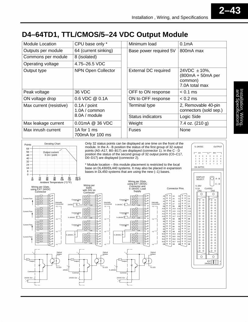
Installation, Wiring,
and Specifications
Installation andS
afety Guidelines
2–43Installation , Wiring, and Specifications
D4–64TD1, TTL/CMOS/5–24 VDC Output ModuleModule Location CPU base only * Minimum load 0.1mA
Outputs per module 64 (current sinking) Base power required 5V 800mA maxCommons per module 8 (isolated)
Operating voltage 4.75–26.5 VDC
Output type NPN Open Collector External DC required 24VDC �10%,(800mA + 50mA percommon)7.0A total max
Peak voltage 36 VDC OFF to ON response < 0.1 ms
ON voltage drop 0.6 VDC @ 0.1A ON to OFF response < 0.2 ms
Max current (resistive) 0.1A / point 1.0A / common
Terminal type 2, Removable 40-pinconnectors (sold sep.)
8.0A / module Status indicators Logic Side
Max leakage current 0.01mA @ 36 VDC Weight 7.4 oz. (210 g)
Max inrush current 1A for 1 ms700mA for 100 ms
Fuses None
0
1
2
3
4
5
6
7
A/C
5–24VDC
D4–64TD1
B/D
OUTPUT
DISPLAYSELECT
0.1A CLASS2CN1
A - B
C - D
0
1
2
3
4
5
6
7
0
1
2
3
4
5
6
7
0
1
2
3
4
5
6
7
5–26V
CN2
EXT24VDC
+–
Derating Chart
08
16243240485664
Points
� �� �� �� �� �� ��
Ambient Temperature (°C/°F)�� �� �� �� ��� ��� ���
°°
Output current0.1A / point
Only 32 status points can be displayed at one time on the front of themodule. In the A - B position the status of the first group of 32 outputpoints (A0–A17, B0–B17) are displayed (connector 1). In the C - Dposition the status of the second group of 32 output points (C0–C17,D0–D17) are displayed (connector 2).
COM
COM
COM
COM
Current Flow
+–24VDC
+
–5–26VDC
+–
5–26VDC
Current Flow
Current Flow
Wiring per32pts.
with 24V onConnector
OpticalIsolator
To LED
V
+–
–
+24VDC Ext
Wiring per 32pts.using EXT 24VDC
Connector
A1
A0
A3
A2
Current Flow
Current Flow
Current Flow
Current Flow
A5
A4
A7
A6
A11
A10
A13
A12
A15
A14
A17
A16
B1
B0
B3
B2
B5
B4
B7
B6
B11
B10
B13
B12
B15
B14
B17
B16
C1
C0
C3
C2
C5
C4
C7
C6
C11
C10
C13
C12
C15
C14
C17
C16
D1
D0
D3
D2
D5
D4
D7
D6
D11
D10
D13
D12
D15
D14
D17
D16
+V
+V
+V
+V
InternallyConnected
Connector Pins
C1 V1
C2 V2
C3 V3
C4 V4
C5 V5
C6 V6
C7 V7
C8 V8
L
L
L
L
L
L
L
L
L
L
L
L
L
L
L
L
L
L
L
L
L
L
L
L
L
L
L
L
L
L
L
L
LOutput
Common
L
L
L
L
L
L
L
L
L
L
L
L
L
L
L
L
L
L
L
L
L
L
L
L
L
L
L
L
L
L
L
L
+V
+V
+V
+V
InternallyConnected
OpticalIsolator
To LED+
–
–
+
24VDC
LOutput
Common
24VDC Ext
COM
COM
COM
COM
Current Flow
+–5–26VDC
+
–5–26VDC
+–
5–26VDC
Current Flow
Current Flow
Wiring per 32pts.using EXT 24VDC
Connector and5–26VDC Load
Supply
L
L
L
L
L
L
L
L
L
L
L
L
L
L
L
L
L
L
L
L
L
L
L
L
L
L
L
L
L
L
L
L
+V
+V
+V
+V
InternallyConnected
OpticalIsolator
To LED+
–
–
+
5–26VDC
LOutput
Common
24VDC Ext+–
+V
+V
+
* Module location – this module placement is restricted to the localbase on DL430/DL440 systems. It may also be placed in expansionbases in DL450 systems that are using the new (–1) bases.
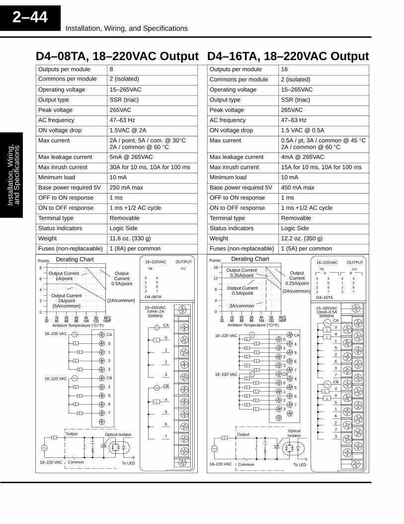
Inst
alla
tion,
Wiri
ng,
and
Spe
cific
atio
nsIn
stal
latio
n an
dS
afet
y G
uide
lines
2–44Installation, Wiring, and Specifications
D4–08TA, 18–220VAC Output D4–16TA, 18–220VAC OutputOutputs per module 8 Outputs per module 16
Commons per module 2 (isolated) Commons per module 2 (isolated)
Operating voltage 15–265VAC Operating voltage 15–265VAC
Output type SSR (triac) Output type SSR (triac)
Peak voltage 265VAC Peak voltage 265VAC
AC frequency 47–63 Hz AC frequency 47–63 Hz
ON voltage drop 1.5VAC @ 2A ON voltage drop 1.5 VAC @ 0.5A
Max current 2A / point, 5A / com. @ 30°C2A / common @ 60 °C
Max current 0.5A / pt, 3A / common @ 45 °C2A / common @ 60 °C
Max leakage current 5mA @ 265VAC Max leakage current 4mA @ 265VAC
Max inrush current 30A for 10 ms, 10A for 100 ms Max inrush current 15A for 10 ms, 10A for 100 ms
Minimum load 10 mA Minimum load 10 mA
Base power required 5V 250 mA max Base power required 5V 450 mA max
OFF to ON response 1 ms OFF to ON response 1 ms
ON to OFF response 1 ms +1/2 AC cycle ON to OFF response 1 ms +1/2 AC cycle
Terminal type Removable Terminal type Removable
Status indicators Logic Side Status indicators Logic Side
Weight 11.6 oz. (330 g) Weight 12.2 oz. (350 g)
Fuses (non-replaceable) 1 (8A) per common Fuses (non-replaceable) 1 (5A) per common
0123
4567
TB FU
18–220VAC
D4–08TA
OUTPUT
CA
0
1
2
3
CB
4
5
6
7
15–265VAC10mA–2A
L
50/60Hz
L
CA
0
1
2
3
CB
4
5
6
7
L
L
L
L
L
L
L
L
18–220 VAC
18–220 VAC
Derating Chart
0
2
4
6
8
Points
� �� �� �� �� �� ��
Ambient Temperature (°C/°F)�� �� �� �� ��� ��� ���
°°
Output Current1A/point
Output Current2A/point
(5A/common)
OutputCurrent
0.5A/point
(2A/common)
Common
L
To LED
Optical IsolatorOutput
18–220 VAC
0123
4567
ATB FU
18–220VAC
D4–16TA
0123
4567
B
OUTPUT
CA
0
4
1
5
2
6
3
7
CB
4
0
5
1
6
2
7
3
15–265VAC10mA–0.5A
L
L
L
L
50/60Hz
CA0
41
52
63
7CB
40
51
62
73
LL
LL
LL
LL
LL
LL
LL
LL
18–220 VAC
18–220 VAC
Derating Chart
0
4
8
12
16
Points
� �� �� �� �� �� ��
Ambient Temperature (°C/°F)�� �� �� �� ��� ��� ���
°°
Output Current0.35A/point
Output Current0.5A/point
OutputCurrent
0.25A/point
(2A/common)
3A/common
Common
L
To LED
OpticalIsolatorOutput
18–220 VAC
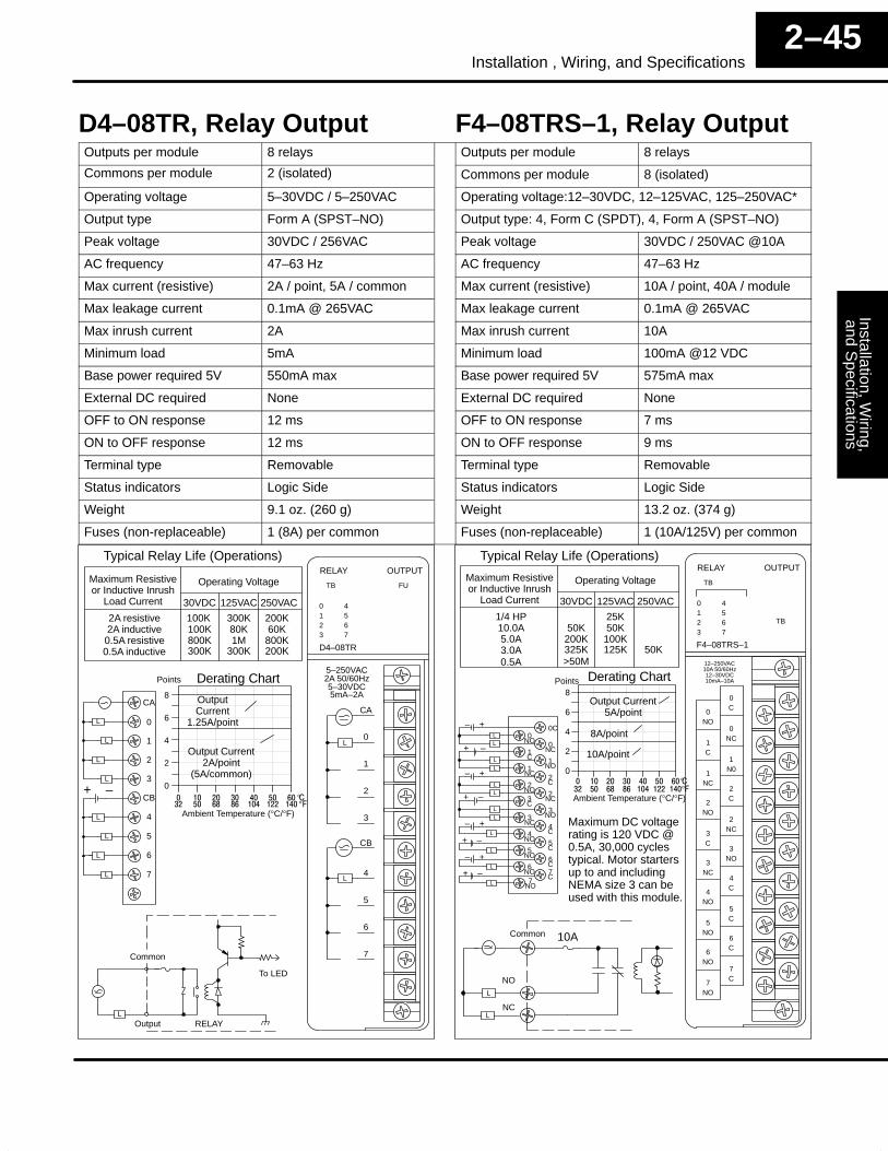
Installation, Wiring,
and Specifications
Installation andS
afety Guidelines
2–45Installation , Wiring, and Specifications
D4–08TR, Relay Output F4–08TRS–1, Relay OutputOutputs per module 8 relays Outputs per module 8 relays
Commons per module 2 (isolated) Commons per module 8 (isolated)
Operating voltage 5–30VDC / 5–250VAC Operating voltage:12–30VDC, 12–125VAC, 125–250VAC*
Output type Form A (SPST–NO) Output type: 4, Form C (SPDT), 4, Form A (SPST–NO)
Peak voltage 30VDC / 256VAC Peak voltage 30VDC / 250VAC @10A
AC frequency 47–63 Hz AC frequency 47–63 Hz
Max current (resistive) 2A / point, 5A / common Max current (resistive) 10A / point, 40A / module
Max leakage current 0.1mA @ 265VAC Max leakage current 0.1mA @ 265VAC
Max inrush current 2A Max inrush current 10A
Minimum load 5mA Minimum load 100mA @12 VDC
Base power required 5V 550mA max Base power required 5V 575mA max
External DC required None External DC required None
OFF to ON response 12 ms OFF to ON response 7 ms
ON to OFF response 12 ms ON to OFF response 9 ms
Terminal type Removable Terminal type Removable
Status indicators Logic Side Status indicators Logic Side
Weight 9.1 oz. (260 g) Weight 13.2 oz. (374 g)
Fuses (non-replaceable) 1 (8A) per common Fuses (non-replaceable) 1 (10A/125V) per common
0123
4567
TB FU
RELAY
D4–08TR
OUTPUT
CA
0
1
2
3
CB
4
5
6
7
L
L
5–250VAC2A 50/60Hz5–30VDC5mA–2A
Typical Relay Life (Operations)
Maximum Resistiveor Inductive Inrush
Load Current
2A resistive2A inductive0.5A resistive0.5A inductive
Operating Voltage
30VDC
100K800K
125VAC
300K80K1M
250VAC
100K
300K 300K
200K60K800K200K
CA
0
1
2
3
CB
4
5
6
7
L
L
L
L
+ –
L
L
L
L
Derating Chart
0
2
4
6
8
Points
� �� �� �� �� �� ��
Ambient Temperature (°C/°F)�� �� �� �� ��� ��� ���
°°
OutputCurrent
1.25A/point
Output Current2A/point
(5A/common)
Common
LRELAY
To LED
Output
TB
RELAY
F4–08TRS–1
OUTPUT
12–250VAC10A 50/60Hz
0123
4567
0C
0NC
1N0
2C
2NC
3NO
4C
5C
6C
7C
0NO
1C
1NC
2NO
3C
3NC
4NO
5NO
6NO
7NO
12–30VDC10mA–10A
TB
Typical Relay Life (Operations)
Maximum Resistiveor Inductive Inrush
Load Current
1/4 HP10.0A5.0A3.0A
Operating Voltage
30VDC
50K200K
125VAC
25K50K100K
250VAC
325K 125K 50K0.5A >50M
0C0
01
11
22
23
33
44
55
66
– +L
L
L
L– +
LL
NC
NO
C
NC
NO
C
C
C7C
NO
C
NC
NO
C
NC
NO
NO
NO7
NO
LL
– +L
L– +
L
L
+ –
+ –
+ –
+ –
Derating Chart
0
2
4
6
8Points
� �� �� �� �� �� ��
Ambient Temperature (°C/°F)�� �� �� �� ��� ��� ���
°°
Output Current5A/point
8A/point
10A/point
L
10ACommon
NO
NCL
Maximum DC voltagerating is 120 VDC @0.5A, 30,000 cyclestypical. Motor startersup to and includingNEMA size 3 can beused with this module.
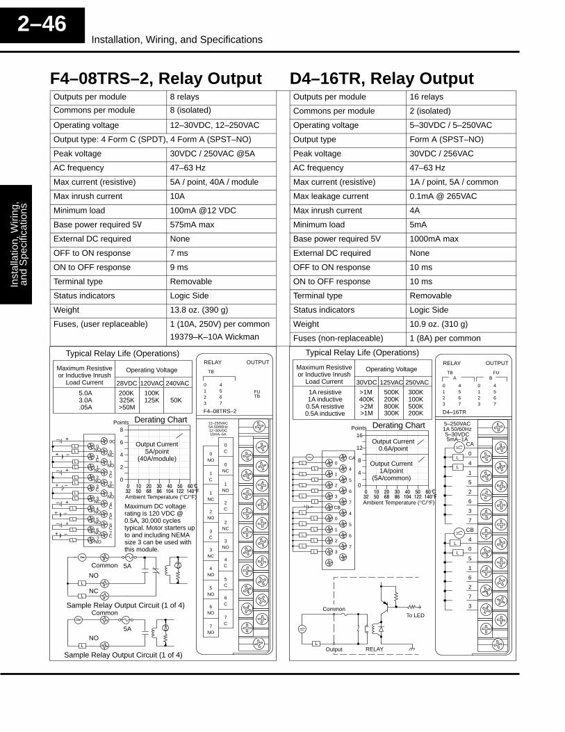
Inst
alla
tion,
Wiri
ng,
and
Spe
cific
atio
nsIn
stal
latio
n an
dS
afet
y G
uide
lines
2–46Installation, Wiring, and Specifications
F4–08TRS–2, Relay Output D4–16TR, Relay OutputOutputs per module 8 relays Outputs per module 16 relays
Commons per module 8 (isolated) Commons per module 2 (isolated)
Operating voltage 12–30VDC, 12–250VAC Operating voltage 5–30VDC / 5–250VAC
Output type: 4 Form C (SPDT), 4 Form A (SPST–NO) Output type Form A (SPST–NO)
Peak voltage 30VDC / 250VAC @5A Peak voltage 30VDC / 256VAC
AC frequency 47–63 Hz AC frequency 47–63 Hz
Max current (resistive) 5A / point, 40A / module Max current (resistive) 1A / point, 5A / common
Max inrush current 10A Max leakage current 0.1mA @ 265VAC
Minimum load 100mA @12 VDC Max inrush current 4A
Base power required 5� 575mA max Minimum load 5mA
External DC required None Base power required 5V 1000mA max
OFF to ON response 7 ms External DC required None
ON to OFF response 9 ms OFF to ON response 10 ms
Terminal type Removable ON to OFF response 10 ms
Status indicators Logic Side Terminal type Removable
Weight 13.8 oz. (390 g) Status indicators Logic Side
Fuses, (user replaceable) 1 (10A, 250V) per common Weight 10.9 oz. (310 g)
19379–K–10A Wickman Fuses (non-replaceable) 1 (8A) per common
0123
4567
ATB FU
RELAY
D4–16TR
0123
4567
B
OUTPUT
CA
0
4
1
5
2
6
3
7
CB
4
0
5
1
6
2
7
3
5–250VAC1A 50/60Hz
L
L
L
L
5–30VDC5mA–1A
Typical Relay Life (Operations)
Maximum Resistiveor Inductive Inrush
Load Current
5.0A3.0A.05A
Operating Voltage
28VDC
325K>50M
120VAC
100K125K
240VAC
200K50K
TB
FU
RELAY
F4–08TRS–2
OUTPUT
12–250VAC5A 50/60Hz
0123
4567
0C
0NC
1NO
2C
2NC
3NO
4C
5C
6C
7C
0NO
1C
1NC
2NO
3C
3NC
4NO
5NO
6NO
7NO
12–30VDC10mA–5A
TB
0C0
01
11
22
23
33
44
55
66
– +L
L
L
L– +
LL
NC
NO
C
NC
NO
C
C
C7C
NO
C
NC
NO
C
NC
NO
NO
NO7
NO
LL
– +L
L– +
L
L
+ –
+ –
+ –
+ –
Derating Chart
0
2
4
6
8Points
� �� �� �� �� �� ��
Ambient Temperature (°C/°F)�� �� �� �� ��� ��� ���
°°
Output Current5A/point
(40A/module)
L
5ACommon
NO
NC
Sample Relay Output Circuit (1 of 4)L
L
5A
Common
NO
Sample Relay Output Circuit (1 of 4)
Typical Relay Life (Operations)
Maximum Resistiveor Inductive Inrush
Load Current
1A resistive1A inductive0.5A resistive0.5A inductive
Operating Voltage
30VDC
400K>2M
125VAC
500K200K800K
250VAC
>1M
>1M 300K
300K100K500K200K
CA0
41
52
63
7CB
40
51
62
73
L
L
L
L
L
L
L
L
L
L
L
L
L
L
L
L
+ –
Derating Chart
0
4
8
12
16Points
Output Current0.6A/point
Output Current1A/point
(5A/common)
Common
LRELAY
To LED
Output
Maximum DC voltagerating is 120 VDC @0.5A, 30,000 cyclestypical. Motor starters upto and including NEMAsize 3 can be used withthis module.
� �� �� �� �� �� ��
Ambient Temperature (°C/°F)�� �� �� �� ��� ��� ���
°°
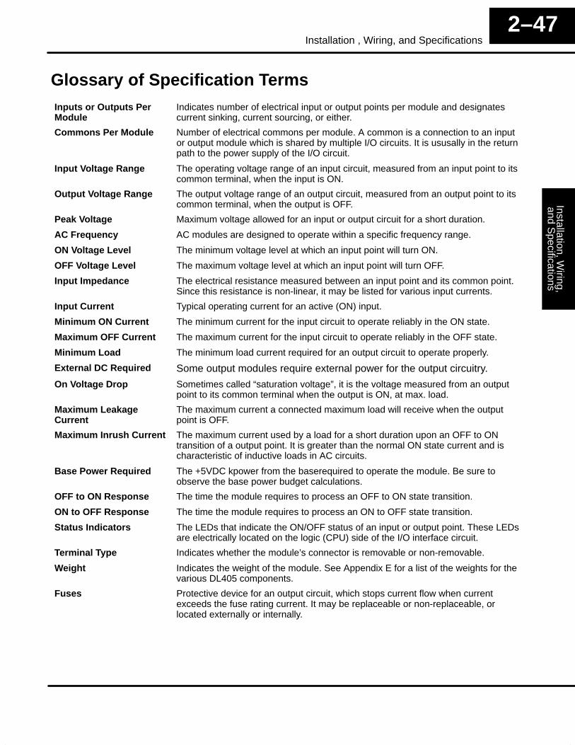
Installation, Wiring,
and Specifications
Installation andS
afety Guidelines
2–47Installation , Wiring, and Specifications
Glossary of Specification TermsInputs or Outputs PerModule
Indicates number of electrical input or output points per module and designatescurrent sinking, current sourcing, or either.
Commons Per Module Number of electrical commons per module. A common is a connection to an inputor output module which is shared by multiple I/O circuits. It is ususally in the returnpath to the power supply of the I/O circuit.
Input Voltage Range The operating voltage range of an input circuit, measured from an input point to itscommon terminal, when the input is ON.
Output Voltage Range The output voltage range of an output circuit, measured from an output point to itscommon terminal, when the output is OFF.
Peak Voltage Maximum voltage allowed for an input or output circuit for a short duration.
AC Frequency AC modules are designed to operate within a specific frequency range.
ON Voltage Level The minimum voltage level at which an input point will turn ON.
OFF Voltage Level The maximum voltage level at which an input point will turn OFF.
Input Impedance The electrical resistance measured between an input point and its common point.Since this resistance is non-linear, it may be listed for various input currents.
Input Current Typical operating current for an active (ON) input.
Minimum ON Current The minimum current for the input circuit to operate reliably in the ON state.
Maximum OFF Current The maximum current for the input circuit to operate reliably in the OFF state.
Minimum Load The minimum load current required for an output circuit to operate properly.
External DC Required Some output modules require external power for the output circuitry.
On Voltage Drop Sometimes called “saturation voltage”, it is the voltage measured from an outputpoint to its common terminal when the output is ON, at max. load.
Maximum LeakageCurrent
The maximum current a connected maximum load will receive when the outputpoint is OFF.
Maximum Inrush Current The maximum current used by a load for a short duration upon an OFF to ONtransition of a output point. It is greater than the normal ON state current and ischaracteristic of inductive loads in AC circuits.
Base Power Required The +5VDC kpower from the baserequired to operate the module. Be sure toobserve the base power budget calculations.
OFF to ON Response The time the module requires to process an OFF to ON state transition.
ON to OFF Response The time the module requires to process an ON to OFF state transition.
Status Indicators The LEDs that indicate the ON/OFF status of an input or output point. These LEDsare electrically located on the logic (CPU) side of the I/O interface circuit.
Terminal Type Indicates whether the module’s connector is removable or non-removable.
Weight Indicates the weight of the module. See Appendix E for a list of the weights for thevarious DL405 components.
Fuses Protective device for an output circuit, which stops current flow when currentexceeds the fuse rating current. It may be replaceable or non-replaceable, orlocated externally or internally.