Embed Size (px)
Citation preview
LA3370
Ordering number : EN619H
PLL FM Multiplex Stereo Demodulatorfor Car Stereo
Monolithic Linear IC
SANYO Electric Co.,Ltd. Semiconductor Bussiness HeadquartersTOKYO OFFICE Tokyo Bldg., 1-10, 1 Chome, Ueno, Taito-ku, TOKYO, 110 JAPAN
63097HA (KOTO) / 8288YT/3018TA/5205MW, TS No.619-1/11
OverviewThe LA3370 is a multiplex IC for FM car stereo, and it has
the following 2 functions through its utilization of the IF
meter output voltage, etc.
1. Stereo noise control (SNC) under which the noise
particular to the FM stereo unit in the weak electric
field is reduced smoothly.
2. High-cut control (HCC) under which the high
frequency is smoothly attenuated. In additioin, the
LA3370 can be, due to its low distortion factor, an IC
for multiplex stereo demodulator which is appropriate
for the car component stereo unit.
Functions• Stereo noise control (SNC terminal)
Through controlling the quality of sound from stereo mode to monaural mode with the voltage applied to the control
pin, the FM stereo noise in the weak electric field is reduced by this function.
• High-cut control function (HCC terminal)
The FM noise in the weak electric field is reduced through the attenuation of high frequency thereof.
Such attenuation can be changed smoothly from "Normal" to "High Cut" by controlling the voltage applied to the
control pin. The volume of "High Cut" can be selected by using an external capacitor.
• Stereo-monaural automatic select
This selection has priority over the stereo noise control. Pilot input prioritized.
• Stoppage of VCO oscillation
When a voltage of 7.5V or higher is applied to the HCC terminal, the oscillation of VCO can be discontinued. In this
case, the stereo lamp does not malfunction.
• With separation control terminal.
Features• Low distortion factor. (0.05% typ. 300mV input, mono)
• The ripple of power source can effectively be rejected. (35dB typ.)
• The range of voltage to be used is wide. (VCC=6.5 to 14V)
• The space factor is advantageous because of the single-end package.
• The printed circuit board can easily be prepared as 3mm pitch is used between the pins.
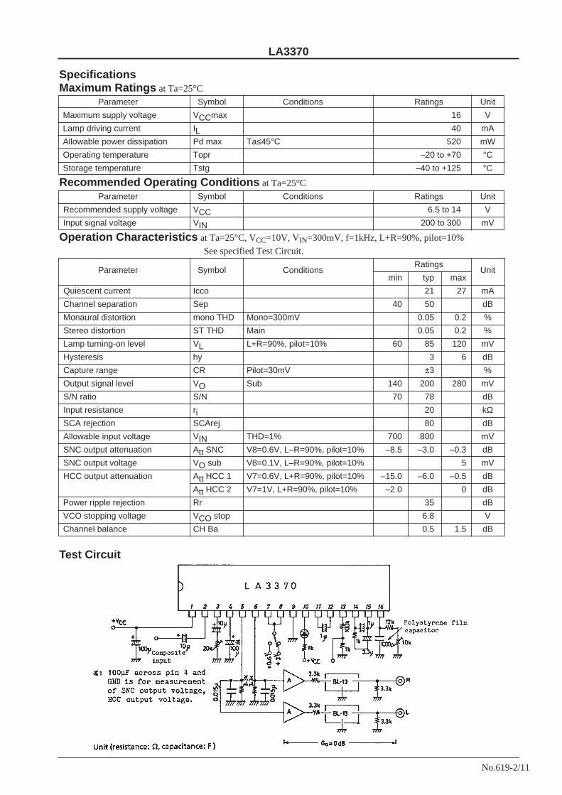
Package Dimensions
unit: mm
3020A-SIP16
[LA3370]
SANYO: SIP16
LA3370
No.619-2/11
SpecificationsMaximum Ratings at Ta=25°C
Parameter Symbol Conditions Ratings Unit
Maximum supply voltage VCCmax 16 V
Lamp driving current IL 40 mA
Allowable power dissipation Pd max Ta≤45°C 520 mW
Operating temperature Topr –20 to +70 °C
Storage temperature Tstg –40 to +125 °C
Recommended Operating Conditions at Ta=25°C
Parameter Symbol Conditions Ratings Unit
Recommended supply voltage VCC 6.5 to 14 V
Input signal voltage VIN 200 to 300 mV
Operation Characteristics at Ta=25°C, VCC=10V, VIN=300mV, f=1kHz, L+R=90%, pilot=10%
See specified Test Circuit.
Parameter Symbol ConditionsRatings
min typ maxUnit
Quiescent current Icco 21 27 mA
Channel separation Sep 40 50 dB
Monaural distortion mono THD Mono=300mV 0.05 0.2 %
Stereo distortion ST THD Main 0.05 0.2 %
Lamp turning-on level VL L+R=90%, pilot=10% 60 85 120 mV
Hysteresis hy 3 6 dB
Capture range CR Pilot=30mV ±3 %
Output signal level VO Sub 140 200 280 mV
S/N ratio S/N 70 78 dB
Input resistance ri 20 kΩSCA rejection SCArej 80 dB
Allowable input voltage VIN THD=1% 700 800 mV
SNC output attenuation Att SNC V8=0.6V, L–R=90%, pilot=10% –8.5 –3.0 –0.3 dB
SNC output voltage VO sub V8=0.1V, L–R=90%, pilot=10% 5 mV
HCC output attenuation Att HCC 1 V7=0.6V, L+R=90%, pilot=10% –15.0 –6.0 –0.5 dB
Att HCC 2 V7=1V, L+R=90%, pilot=10% –2.0 0 dB
Power ripple rejection Rr 35 dB
VCO stopping voltage VCO stop 6.8 V
Channel balance CH Ba 0.5 1.5 dB
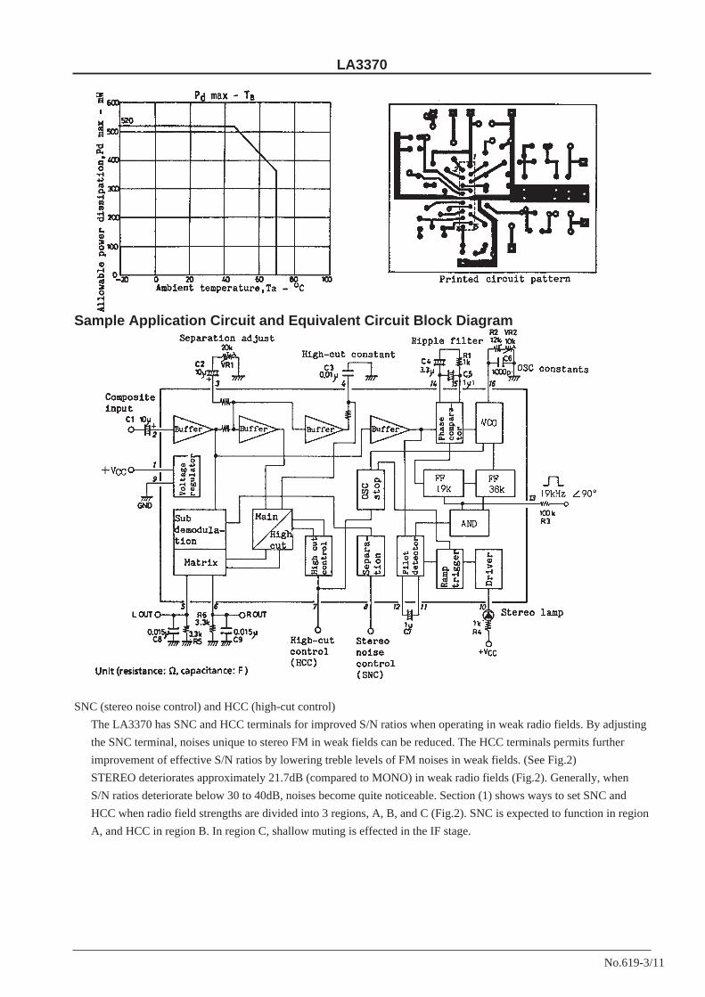
Test Circuit
LA3370
No.619-3/11
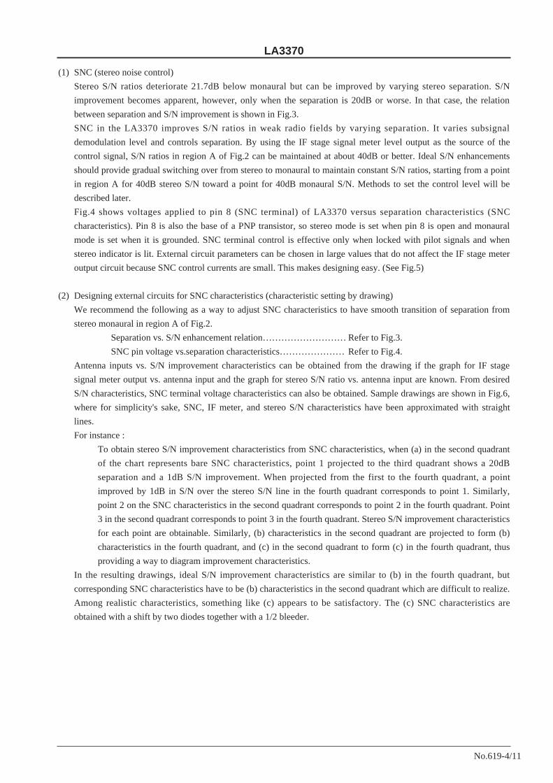
SNC (stereo noise control) and HCC (high-cut control)
The LA3370 has SNC and HCC terminals for improved S/N ratios when operating in weak radio fields. By adjusting
the SNC terminal, noises unique to stereo FM in weak fields can be reduced. The HCC terminals permits further
improvement of effective S/N ratios by lowering treble levels of FM noises in weak fields. (See Fig.2)
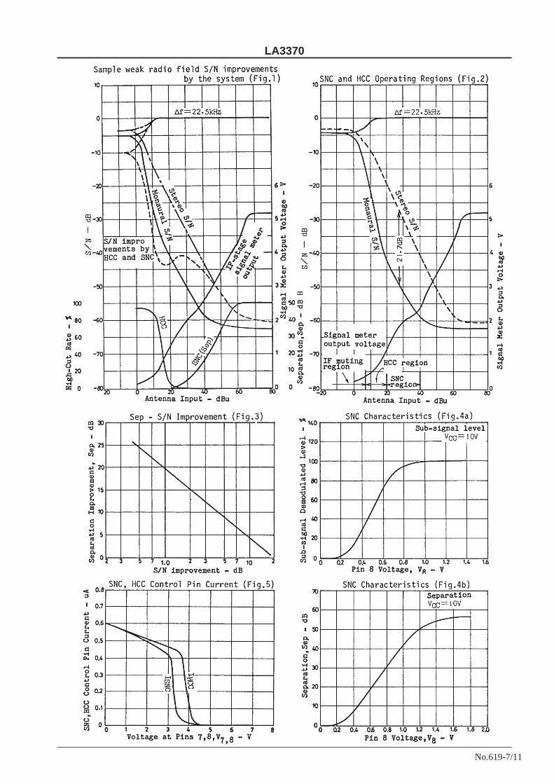
STEREO deteriorates approximately 21.7dB (compared to MONO) in weak radio fields (Fig.2). Generally, when
S/N ratios deteriorate below 30 to 40dB, noises become quite noticeable. Section (1) shows ways to set SNC and
HCC when radio field strengths are divided into 3 regions, A, B, and C (Fig.2). SNC is expected to function in region
A, and HCC in region B. In region C, shallow muting is effected in the IF stage.
Sample Application Circuit and Equivalent Circuit Block Diagram
LA3370
No.619-4/11
(1) SNC (stereo noise control)
Stereo S/N ratios deteriorate 21.7dB below monaural but can be improved by varying stereo separation. S/N
improvement becomes apparent, however, only when the separation is 20dB or worse. In that case, the relation
between separation and S/N improvement is shown in Fig.3.
SNC in the LA3370 improves S/N ratios in weak radio fields by varying separation. It varies subsignal
demodulation level and controls separation. By using the IF stage signal meter level output as the source of the
control signal, S/N ratios in region A of Fig.2 can be maintained at about 40dB or better. Ideal S/N enhancements
should provide gradual switching over from stereo to monaural to maintain constant S/N ratios, starting from a point
in region A for 40dB stereo S/N toward a point for 40dB monaural S/N. Methods to set the control level will be
described later.
Fig.4 shows voltages applied to pin 8 (SNC terminal) of LA3370 versus separation characteristics (SNC
characteristics). Pin 8 is also the base of a PNP transistor, so stereo mode is set when pin 8 is open and monaural
mode is set when it is grounded. SNC terminal control is effective only when locked with pilot signals and when
stereo indicator is lit. External circuit parameters can be chosen in large values that do not affect the IF stage meter
output circuit because SNC control currents are small. This makes designing easy. (See Fig.5)
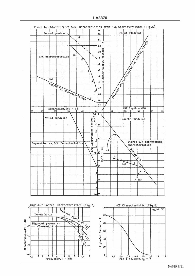
(2) Designing external circuits for SNC characteristics (characteristic setting by drawing)
We recommend the following as a way to adjust SNC characteristics to have smooth transition of separation from
stereo monaural in region A of Fig.2.
Separation vs. S/N enhancement relation……………………… Refer to Fig.3.
SNC pin voltage vs.separation characteristics………………… Refer to Fig.4.
Antenna inputs vs. S/N improvement characteristics can be obtained from the drawing if the graph for IF stage
signal meter output vs. antenna input and the graph for stereo S/N ratio vs. antenna input are known. From desired
S/N characteristics, SNC terminal voltage characteristics can also be obtained. Sample drawings are shown in Fig.6,
where for simplicity's sake, SNC, IF meter, and stereo S/N characteristics have been approximated with straight
lines.
For instance :
To obtain stereo S/N improvement characteristics from SNC characteristics, when (a) in the second quadrant
of the chart represents bare SNC characteristics, point 1 projected to the third quadrant shows a 20dB
separation and a 1dB S/N improvement. When projected from the first to the fourth quadrant, a point
improved by 1dB in S/N over the stereo S/N line in the fourth quadrant corresponds to point 1. Similarly,
point 2 on the SNC characteristics in the second quadrant corresponds to point 2 in the fourth quadrant. Point
3 in the second quadrant corresponds to point 3 in the fourth quadrant. Stereo S/N improvement characteristics
for each point are obtainable. Similarly, (b) characteristics in the second quadrant are projected to form (b)
characteristics in the fourth quadrant, and (c) in the second quadrant to form (c) in the fourth quadrant, thus
providing a way to diagram improvement characteristics.
In the resulting drawings, ideal S/N improvement characteristics are similar to (b) in the fourth quadrant, but
corresponding SNC characteristics have to be (b) characteristics in the second quadrant which are difficult to realize.
Among realistic characteristics, something like (c) appears to be satisfactory. The (c) SNC characteristics are
obtained with a shift by two diodes together with a 1/2 bleeder.
LA3370
No.619-5/11
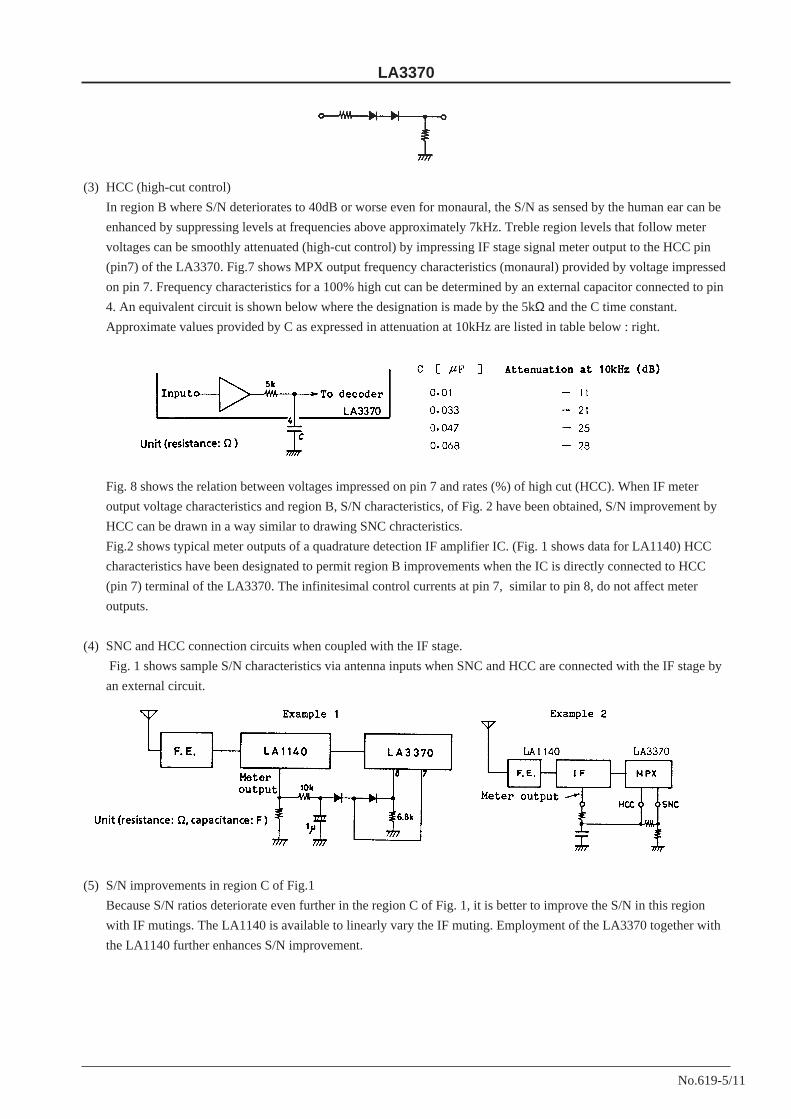
(3) HCC (high-cut control)
In region B where S/N deteriorates to 40dB or worse even for monaural, the S/N as sensed by the human ear can be
enhanced by suppressing levels at frequencies above approximately 7kHz. Treble region levels that follow meter
voltages can be smoothly attenuated (high-cut control) by impressing IF stage signal meter output to the HCC pin
(pin7) of the LA3370. Fig.7 shows MPX output frequency characteristics (monaural) provided by voltage impressed
on pin 7. Frequency characteristics for a 100% high cut can be determined by an external capacitor connected to pin
4. An equivalent circuit is shown below where the designation is made by the 5kΩ and the C time constant.
Approximate values provided by C as expressed in attenuation at 10kHz are listed in table below : right.
Fig. 8 shows the relation between voltages impressed on pin 7 and rates (%) of high cut (HCC). When IF meter
output voltage characteristics and region B, S/N characteristics, of Fig. 2 have been obtained, S/N improvement by
HCC can be drawn in a way similar to drawing SNC chracteristics.
Fig.2 shows typical meter outputs of a quadrature detection IF amplifier IC. (Fig. 1 shows data for LA1140) HCC
characteristics have been designated to permit region B improvements when the IC is directly connected to HCC
(pin 7) terminal of the LA3370. The infinitesimal control currents at pin 7, similar to pin 8, do not affect meter
outputs.
(4) SNC and HCC connection circuits when coupled with the IF stage.
Fig. 1 shows sample S/N characteristics via antenna inputs when SNC and HCC are connected with the IF stage by
an external circuit.
(5) S/N improvements in region C of Fig.1
Because S/N ratios deteriorate even further in the region C of Fig. 1, it is better to improve the S/N in this region
with IF mutings. The LA1140 is available to linearly vary the IF muting. Employment of the LA3370 together with
the LA1140 further enhances S/N improvement.
LA3370
No.619-6/11
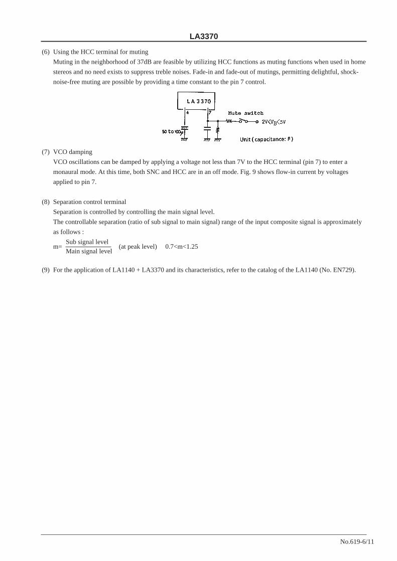
(6) Using the HCC terminal for muting
Muting in the neighborhood of 37dB are feasible by utilizing HCC functions as muting functions when used in home
stereos and no need exists to suppress treble noises. Fade-in and fade-out of mutings, permitting delightful, shock-
noise-free muting are possible by providing a time constant to the pin 7 control.
(7) VCO damping
VCO oscillations can be damped by applying a voltage not less than 7V to the HCC terminal (pin 7) to enter a
monaural mode. At this time, both SNC and HCC are in an off mode. Fig. 9 shows flow-in current by voltages
applied to pin 7.
(8) Separation control terminal
Separation is controlled by controlling the main signal level.
The controllable separation (ratio of sub signal to main signal) range of the input composite signal is approximately
as follows :
Sub signal levelm=
Main signal level(at peak level) 0.7<m<1.25
(9) For the application of LA1140 + LA3370 and its characteristics, refer to the catalog of the LA1140 (No. EN729).
LA3370
No.619-7/11
LA3370
No619-8/11

LA3370
No.619-9/11
LA3370
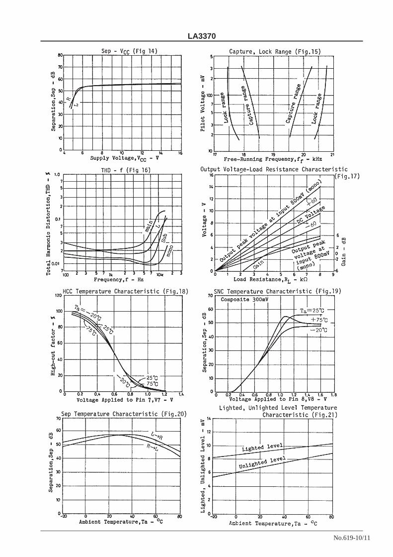
No.619-10/11
LA3370
No.619-11/11
No products described or contained herein are intended for use in surgical implants, life-support systems, aerospace equipment, nuclear power control systems, vehicles, disaster/crime-prevention equipment and the like, the failure of which may directly or indirectly cause injury, death or property lose.
Anyone purchasing any products described or contained herein for an above-mentioned use shall: Accept full responsibility and indemnify and defend SANYO ELECTRIC CO., LTD., its affiliates, subsidiaries and distributors and all their officers and employees, jointly and severally, against any and all claims and litigation and all damages, cost and expenses associated with such use: Not impose any responsibilty for any fault or negligence which may be cited in any such claim or litigation on SANYO ELECTRIC CO., LTD., its affiliates, subsidiaries and distributors or any of their officers and employees jointly or severally.
Information (including circuit diagrams and circuit parameters) herein is for example only; it is not guarant-eed for volume production. SANYO believes information herein is accurate and reliable, but no guarantees are made or implied regarding its use or any infringements of intellectual property rights or other rights of third parties.
This catalog provides information as of June, 1997. Specifications and information herein are subject to
change without notice.

This datasheet has been download from:
www.datasheetcatalog.com
Datasheets for electronics components.