Embed Size (px)
Citation preview
Pneumatic Power & Control
This page is part of a complete catalog which contains technical and safety data that must be reviewed when selecting a product.
Hydraulic P
ower &
Control
Pneum
atic Pow
er & C
ontrolF
luid Conveying
Miscellaneous P
roductsIndexes &
Technical Information
Category Page
771 1999-2016 Hydraulic Supply Co. • 1-800-507-9651 • www.hydraulic-supply.com
Pneumatic Cylinders . . . . . . . . . . . . . . . . . . . . . . . . . . . . . . . . . . . . . . . . . . . . . . . . . . . . . . . . . . . . . . . . . . . . . 772American Cylinder 76 Series • Aluminum Barrel • 3/4 to 2-1/2 Inch Bore. . . . . . . . . . . . . . . . . . . . . . . . . . . . . 772American Cylinder Stainless Steel Series • Stainless Steel Barrel • 7/16 to 1-1/2 Inch Bore . . . . . . . . . . . . . . 774Aro Silverair™ Series • Stainless Steel Barrel • 1/2 to 2-1/2 Inch Bore . . . . . . . . . . . . . . . . . . . . . . . . . . . . . . 775
Pneumatic Valves & Accessories. . . . . . . . . . . . . . . . . . . . . . . . . . . . . . . . . . . . . . . . . . . . . . . . . . . . . . . . . . . 777Aro® Aro-Flo Series FRL's . . . . . . . . . . . . . . . . . . . . . . . . . . . . . . . . . . . . . . . . . . . . . . . . . . . . . . . . . . . . . . . . 794Aro® Aro-Flo Series Filters. . . . . . . . . . . . . . . . . . . . . . . . . . . . . . . . . . . . . . . . . . . . . . . . . . . . . . . . . . . . . . . . 795Aro® Aro-Flo Series Regulators . . . . . . . . . . . . . . . . . . . . . . . . . . . . . . . . . . . . . . . . . . . . . . . . . . . . . . . . . . . . 796Aro® Aro-Flo Series Piggyback Filter/Regulators. . . . . . . . . . . . . . . . . . . . . . . . . . . . . . . . . . . . . . . . . . . . . . . 797Aro® Aro-Flo Series Lubricators. . . . . . . . . . . . . . . . . . . . . . . . . . . . . . . . . . . . . . . . . . . . . . . . . . . . . . . . . . . . 798Numatics FlexiBlok Filters . . . . . . . . . . . . . . . . . . . . . . . . . . . . . . . . . . . . . . . . . . . . . . . . . . . . . . . . . . . . . . . . 800Numatics FlexiBlok Regulators. . . . . . . . . . . . . . . . . . . . . . . . . . . . . . . . . . . . . . . . . . . . . . . . . . . . . . . . . . . . . 801Numatics FlexiBlok Piggyback Filter/Regulators . . . . . . . . . . . . . . . . . . . . . . . . . . . . . . . . . . . . . . . . . . . . . . . 801Numatics FlexiBlok Lubricators . . . . . . . . . . . . . . . . . . . . . . . . . . . . . . . . . . . . . . . . . . . . . . . . . . . . . . . . . . . . 802Numatics Filters . . . . . . . . . . . . . . . . . . . . . . . . . . . . . . . . . . . . . . . . . . . . . . . . . . . . . . . . . . . . . . . . . . . . . . . . 803
Pneumatic System Accessories. . . . . . . . . . . . . . . . . . . . . . . . . . . . . . . . . . . . . . . . . . . . . . . . . . . . . . . . . . . . 804Air Tool Hose Assemblies. . . . . . . . . . . . . . . . . . . . . . . . . . . . . . . . . . . . . . . . . . . . . . . . . . . . . . . . . . . . . . . . . 804Aro® Air Line Lubricating Oil . . . . . . . . . . . . . . . . . . . . . . . . . . . . . . . . . . . . . . . . . . . . . . . . . . . . . . . . . . . . . . 805Safety Pop-Off Valves . . . . . . . . . . . . . . . . . . . . . . . . . . . . . . . . . . . . . . . . . . . . . . . . . . . . . . . . . . . . . . . . . . . 806Pneumatic Cylinders Technical Information . . . . . . . . . . . . . . . . . . . . . . . . . . . . . . . . . . . . . . . . . . . . . . . . . . . 807
This page is part of a complete catalog which contains technical and safety data that must be reviewed when selecting a product
Pneumatic Cylinders
Hyd
raul
ic P
ower
& C
ontr
olP
neum
atic
Pow
er &
Con
trol
Flu
id C
onve
ying
Mis
cella
neou
s P
rodu
cts
Inde
xes
& T
echn
ical
Info
rmat
ion
772 1999-2016 Hydraulic Supply Co. • 1-800-507-9651 • www.hydraulic-supply.com
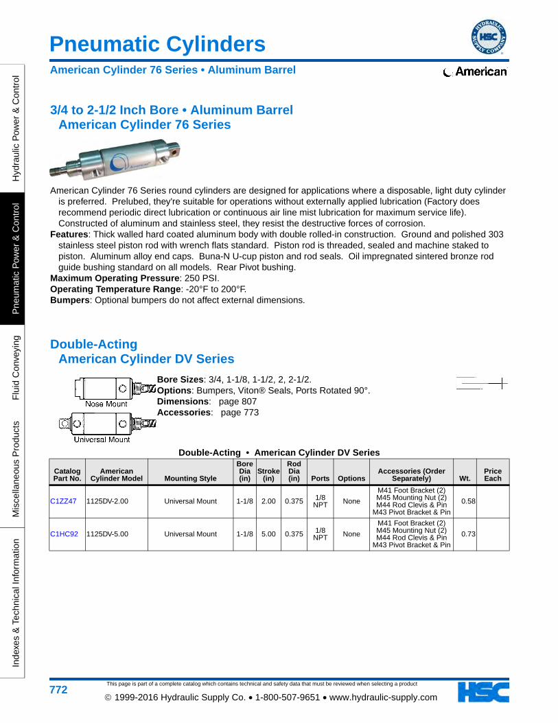
3/4 to 2-1/2 Inch Bore • Aluminum Barrel American Cylinder 76 Series
American Cylinder 76 Series round cylinders are designed for applications where a disposable, light duty cylinder is preferred. Prelubed, they're suitable for operations without externally applied lubrication (Factory does recommend periodic direct lubrication or continuous air line mist lubrication for maximum service life). Constructed of aluminum and stainless steel, they resist the destructive forces of corrosion.
Features: Thick walled hard coated aluminum body with double rolled-in construction. Ground and polished 303 stainless steel piston rod with wrench flats standard. Piston rod is threaded, sealed and machine staked to piston. Aluminum alloy end caps. Buna-N U-cup piston and rod seals. Oil impregnated sintered bronze rod guide bushing standard on all models. Rear Pivot bushing.
Maximum Operating Pressure: 250 PSI.Operating Temperature Range: -20°F to 200°F.Bumpers: Optional bumpers do not affect external dimensions.
Double-Acting American Cylinder DV Series
Bore Sizes: 3/4, 1-1/8, 1-1/2, 2, 2-1/2. Options: Bumpers, Viton® Seals, Ports Rotated 90°. Dimensions: page 807Accessories: page 773
Double-Acting • American Cylinder DV Series
Catalog Part No.
American Cylinder Model Mounting Style
Bore Dia (in)
Stroke (in)
Rod Dia (in) Ports Options
Accessories (Order Separately) Wt.
Price Each
C1ZZ47 1125DV-2.00 Universal Mount 1-1/8 2.00 0.375 1/8 NPT None
M41 Foot Bracket (2) M45 Mounting Nut (2) M44 Rod Clevis & Pin
M43 Pivot Bracket & Pin
0.58
C1HC92 1125DV-5.00 Universal Mount 1-1/8 5.00 0.375 1/8 NPT None
M41 Foot Bracket (2) M45 Mounting Nut (2) M44 Rod Clevis & Pin
M43 Pivot Bracket & Pin
0.73
American Cylinder 76 Series • Aluminum Barrel
Pneumatic Cylinders
This page is part of a complete catalog which contains technical and safety data that must be reviewed when selecting a product
Hydraulic P
ower &
Control
Pneum
atic Pow
er & C
ontrolF
luid Conveying
Miscellaneous P
roductsIndexes &
Technical Information
773 1999-2016 Hydraulic Supply Co. • 1-800-507-9651 • www.hydraulic-supply.com
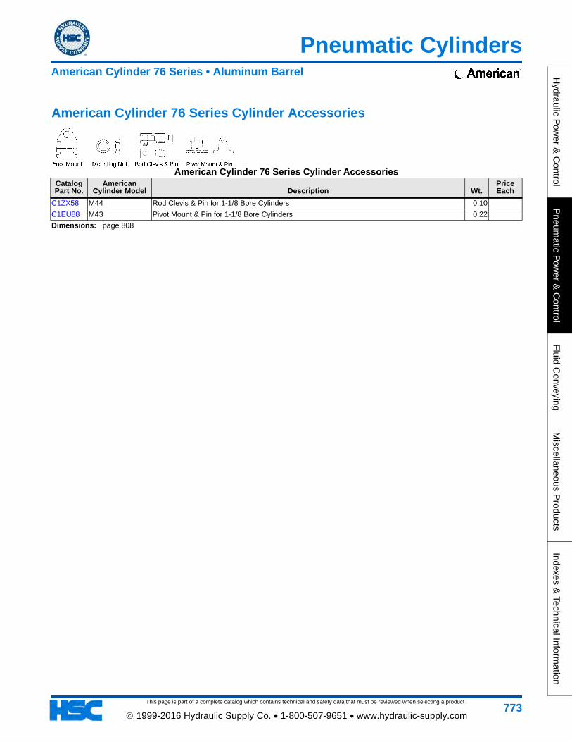
American Cylinder 76 Series Cylinder Accessories
American Cylinder 76 Series Cylinder AccessoriesCatalog Part No.
American Cylinder Model Description Wt.
Price Each
C1ZX58 M44 Rod Clevis & Pin for 1-1/8 Bore Cylinders 0.10
C1EU88 M43 Pivot Mount & Pin for 1-1/8 Bore Cylinders 0.22
Dimensions: page 808
American Cylinder 76 Series • Aluminum Barrel
This page is part of a complete catalog which contains technical and safety data that must be reviewed when selecting a product
Pneumatic Cylinders
Hyd
raul
ic P
ower
& C
ontr
olP
neum
atic
Pow
er &
Con
trol
Flu
id C
onve
ying
Mis
cella
neou
s P
rodu
cts
Inde
xes
& T
echn
ical
Info
rmat
ion
774 1999-2016 Hydraulic Supply Co. • 1-800-507-9651 • www.hydraulic-supply.com
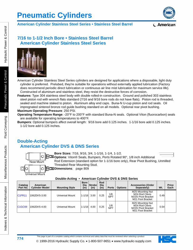
7/16 to 1-1/2 Inch Bore • Stainless Steel Barrel American Cylinder Stainless Steel Series
American Cylinder Stainless Steel Series cylinders are designed for applications where a disposable, light duty cylinder is preferred. Prelubed, they're suitable for operations without externally applied lubrication (Factory does recommend periodic direct lubrication or continuous air line mist lubrication for maximum service life). Constructed of aluminum and stainless steel, they resist the destructive forces of corrosion.
Features: Type 304 stainless steel body with double rolled-in construction. Ground and polished 303 stainless steel piston rod with wrench flats standard (7/16 and 9/16 bore rods do not have flats). Piston rod is threaded, sealed and machine staked to piston. Aluminum alloy end caps. Buna-N U-cup piston and rod seals. Oil impregnated sintered bronze rod guide bushing standard on all models. Optional rear pivot bushing.
Maximum Operating Pressure: 250 PSI.Operating Temperature Range: -20°F to 200°F with standard Buna-N seals. Optional Viton (fluorocarbon) seals
are available for operating temperatures to 400°F.Bumpers: Optional bumpers affect overall length: 9/16 bore add 0.125 inches. 1-1/16 bore add 0.125 inches.
1-1/2 bore add 0.125 inches.
Double-Acting American Cylinder DVS & DNS Series
Bore Sizes: 7/16, 9/16, 3/4, 1-1/16, 1-1/4, 1-1/2. Options: Viton® Seals, Bumpers, Ports Rotated 90°, 1/8 inch Additional Rod Extension (standard option for 1-1/16 bore only), Rear Pivot Bushing, Unmilled Threaded Rear Mounting Stud. Dimensions: page 809
Double-Acting • American Cylinder DVS & DNS Series
Catalog Part No.
American Cylinder Model Mounting Style
Bore Dia (in)
Stroke (in)
Rod Dia (in) Ports Options
Accessories (Order Separately) Wt.
Price Each
C1FR11 1062DVS-3.00 Universal Mount 1-1/16 3.00 0.25 1/8 NPT
M25 Mounting Nut M24 Rod Clevis
M23S Pivot Bracket M21 Foot Bracket
0.49
C1GC69 1062DVS-4.00 Universal Mount 1-1/16 4.00 0.25 1/8 NPT
M25 Mounting Nut M24 Rod Clevis
M23S Pivot Bracket M21 Foot Bracket
0.54
American Cylinder Stainless Steel Series • Stainless Steel Barrel
Pneumatic Cylinders
This page is part of a complete catalog which contains technical and safety data that must be reviewed when selecting a product
Hydraulic P
ower &
Control
Pneum
atic Pow
er & C
ontrolF
luid Conveying
Miscellaneous P
roductsIndexes &
Technical Information
775 1999-2016 Hydraulic Supply Co. • 1-800-507-9651 • www.hydraulic-supply.com
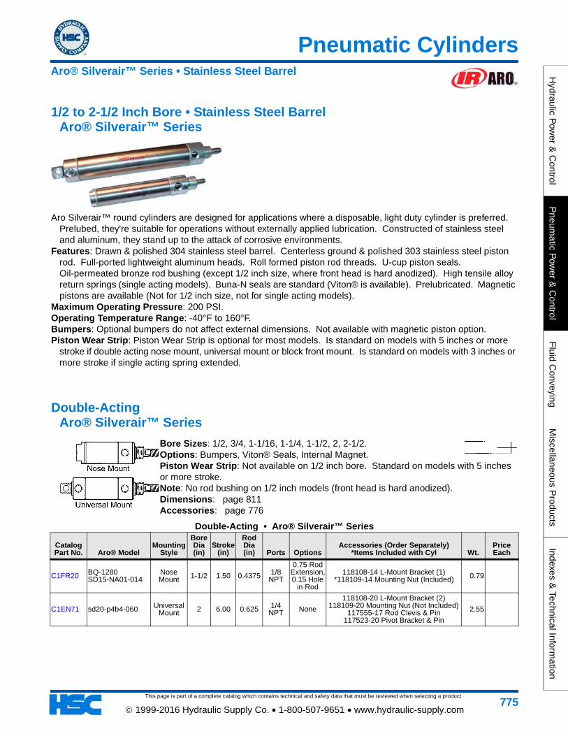
1/2 to 2-1/2 Inch Bore • Stainless Steel Barrel Aro® Silverair™ Series
Aro Silverair™ round cylinders are designed for applications where a disposable, light duty cylinder is preferred. Prelubed, they're suitable for operations without externally applied lubrication. Constructed of stainless steel and aluminum, they stand up to the attack of corrosive environments.
Features: Drawn & polished 304 stainless steel barrel. Centerless ground & polished 303 stainless steel piston rod. Full-ported lightweight aluminum heads. Roll formed piston rod threads. U-cup piston seals. Oil-permeated bronze rod bushing (except 1/2 inch size, where front head is hard anodized). High tensile alloy return springs (single acting models). Buna-N seals are standard (Viton® is available). Prelubricated. Magnetic pistons are available (Not for 1/2 inch size, not for single acting models).
Maximum Operating Pressure: 200 PSI.Operating Temperature Range: -40°F to 160°F.Bumpers: Optional bumpers do not affect external dimensions. Not available with magnetic piston option.Piston Wear Strip: Piston Wear Strip is optional for most models. Is standard on models with 5 inches or more
stroke if double acting nose mount, universal mount or block front mount. Is standard on models with 3 inches or more stroke if single acting spring extended.
Double-Acting Aro® Silverair™ Series
Bore Sizes: 1/2, 3/4, 1-1/16, 1-1/4, 1-1/2, 2, 2-1/2. Options: Bumpers, Viton® Seals, Internal Magnet. Piston Wear Strip: Not available on 1/2 inch bore. Standard on models with 5 inches or more stroke. Note: No rod bushing on 1/2 inch models (front head is hard anodized). Dimensions: page 811Accessories: page 776
Double-Acting • Aro® Silverair™ Series
Catalog Part No. Aro® Model
Mounting Style
Bore Dia (in)
Stroke (in)
Rod Dia (in) Ports Options
Accessories (Order Separately) *Items Included with Cyl Wt.
Price Each
C1FR20 BQ-1280 SD15-NA01-014
Nose Mount 1-1/2 1.50 0.4375 1/8
NPT
0.75 Rod Extension, 0.15 Hole
in Rod
118108-14 L-Mount Bracket (1) *118109-14 Mounting Nut (Included) 0.79
C1EN71 sd20-p4b4-060 Universal Mount 2 6.00 0.625 1/4
NPT None
118108-20 L-Mount Bracket (2) 118109-20 Mounting Nut (Not Included)
117555-17 Rod Clevis & Pin 117523-20 Pivot Bracket & Pin
2.55
Aro® Silverair™ Series • Stainless Steel Barrel

This page is part of a complete catalog which contains technical and safety data that must be reviewed when selecting a product
Pneumatic Cylinders
Hyd
raul
ic P
ower
& C
ontr
olP
neum
atic
Pow
er &
Con
trol
Flu
id C
onve
ying
Mis
cella
neou
s P
rodu
cts
Inde
xes
& T
echn
ical
Info
rmat
ion
776 1999-2016 Hydraulic Supply Co. • 1-800-507-9651 • www.hydraulic-supply.com
Aro® Silverair™ Series Cylinder Accessories
Aro® Silverair™ Series Cylinder AccessoriesCatalog Part No. Aro® Model Description Wt.
Price Each
C1ES36 117555-17 Rod Clevis & Pin Kit for 1-3/4, 2, and 2-1/2 Bore Cylinders 0.21
Materials: Bright zinc plated steel. Dimensions: page 812
Aro® Silverair™ Series • Stainless Steel Barrel
Pneumatic Valves & Accessories
This page is part of a complete catalog which contains technical and safety data that must be reviewed when selecting a product.
Hydraulic P
ower &
Control
Pneum
atic Pow
er & C
ontrolF
luid Conveying
Miscellaneous P
roductsIndexes &
Technical Information
Category Page
777 1999-2016 Hydraulic Supply Co. • 1-800-507-9651 • www.hydraulic-supply.com
Note: Valves that can be used for both Pneumatic & Hydraulic service (certain Ball Valves, Check Valves, Flow Control Valves, Needle Valves & Plug Valves) are located in the Hydraulic Power & Control section. See the alphabetical list on page 238
Ball Valves . . . . . . . . . . . . . . . . . . . . . . . . . . . . . . . . . . . . . . . . . . . . . . . . . . . . . . . . . . . . . . . . . . . . . . . . . . . . . 778Directional - Manually Operated . . . . . . . . . . . . . . . . . . . . . . . . . . . . . . . . . . . . . . . . . . . . . . . . . . . . . . . . . . . . 779
Aro® 460 Series • 2-Way & 3-Way • To 7.5 SCFM . . . . . . . . . . . . . . . . . . . . . . . . . . . . . . . . . . . . . . . . . . . . . 779Aro® 50 Series • 3-Way & 4-Way • To 16 SCFM . . . . . . . . . . . . . . . . . . . . . . . . . . . . . . . . . . . . . . . . . . . . . . . 779Aro® E Series • 3-Way & 4-Way • To 26 SCFM. . . . . . . . . . . . . . . . . . . . . . . . . . . . . . . . . . . . . . . . . . . . . . . . 780Numatics L2 Inline 4-Way • To 79 SCFM . . . . . . . . . . . . . . . . . . . . . . . . . . . . . . . . . . . . . . . . . . . . . . . . . . . . . 780
Directional - Pilot Operated. . . . . . . . . . . . . . . . . . . . . . . . . . . . . . . . . . . . . . . . . . . . . . . . . . . . . . . . . . . . . . . . 781Aro® Alpha™ Series (Body Ported) • 4-Way • To 61 SCFM . . . . . . . . . . . . . . . . . . . . . . . . . . . . . . . . . . . . . . 781
Directional - Solenoid Operated . . . . . . . . . . . . . . . . . . . . . . . . . . . . . . . . . . . . . . . . . . . . . . . . . . . . . . . . . . . . 782Aro® CAT Series 3-Way NC & NO • To 6.9 SCFM . . . . . . . . . . . . . . . . . . . . . . . . . . . . . . . . . . . . . . . . . . . . . 782Numatics 92280 Inline 4-Way • To 17.7 SCFM . . . . . . . . . . . . . . . . . . . . . . . . . . . . . . . . . . . . . . . . . . . . . . . . 783Numatics L01 Inline 4-Way • To 9.3 SCFM . . . . . . . . . . . . . . . . . . . . . . . . . . . . . . . . . . . . . . . . . . . . . . . . . . . 784Aro® Alpha™ Series (Body Ported) • 4-Way • To 61 SCFM . . . . . . . . . . . . . . . . . . . . . . . . . . . . . . . . . . . . . . 785Numatics L2 Inline 4-Way • To 79 SCFM . . . . . . . . . . . . . . . . . . . . . . . . . . . . . . . . . . . . . . . . . . . . . . . . . . . . . 786Aro® MaxAir™ Series • 4-Way • To 167 SCFM . . . . . . . . . . . . . . . . . . . . . . . . . . . . . . . . . . . . . . . . . . . . . . . . 787
Drain Cocks . . . . . . . . . . . . . . . . . . . . . . . . . . . . . . . . . . . . . . . . . . . . . . . . . . . . . . . . . . . . . . . . . . . . . . . . . . . . 788Flow Control Valves. . . . . . . . . . . . . . . . . . . . . . . . . . . . . . . . . . . . . . . . . . . . . . . . . . . . . . . . . . . . . . . . . . . . . . 789
Aro® Right Angle . . . . . . . . . . . . . . . . . . . . . . . . . . . . . . . . . . . . . . . . . . . . . . . . . . . . . . . . . . . . . . . . . . . . . . . 789Aro® Inline . . . . . . . . . . . . . . . . . . . . . . . . . . . . . . . . . . . . . . . . . . . . . . . . . . . . . . . . . . . . . . . . . . . . . . . . . . . . 790
Valve Exhaust Port Mufflers & Speed Controls . . . . . . . . . . . . . . . . . . . . . . . . . . . . . . . . . . . . . . . . . . . . . . . 791Aro® 50 Series . . . . . . . . . . . . . . . . . . . . . . . . . . . . . . . . . . . . . . . . . . . . . . . . . . . . . . . . . . . . . . . . . . . . . . . 814Aro® E Series . . . . . . . . . . . . . . . . . . . . . . . . . . . . . . . . . . . . . . . . . . . . . . . . . . . . . . . . . . . . . . . . . . . . . . . . 815Aro® Alpha Series . . . . . . . . . . . . . . . . . . . . . . . . . . . . . . . . . . . . . . . . . . . . . . . . . . . . . . . . . . . . . . . . . . . . . 816
Directional - Solenoid Operated . . . . . . . . . . . . . . . . . . . . . . . . . . . . . . . . . . . . . . . . . . . . . . . . . . . . . . . . . . . . 817Aro® CAT Series . . . . . . . . . . . . . . . . . . . . . . . . . . . . . . . . . . . . . . . . . . . . . . . . . . . . . . . . . . . . . . . . . . . . . . 817Aro® Alpha Series . . . . . . . . . . . . . . . . . . . . . . . . . . . . . . . . . . . . . . . . . . . . . . . . . . . . . . . . . . . . . . . . . . . . . 817Aro® MaxAir Series . . . . . . . . . . . . . . . . . . . . . . . . . . . . . . . . . . . . . . . . . . . . . . . . . . . . . . . . . . . . . . . . . . . . 818Aro® Sierra® 18 Series . . . . . . . . . . . . . . . . . . . . . . . . . . . . . . . . . . . . . . . . . . . . . . . . . . . . . . . . . . . . . . . . . 818
This page is part of a complete catalog which contains technical and safety data that must be reviewed when selecting a product
Pneumatic Valves & Accessories
Hyd
raul
ic P
ower
& C
ontr
olP
neum
atic
Pow
er &
Con
trol
Flu
id C
onve
ying
Mis
cella
neou
s P
rodu
cts
Inde
xes
& T
echn
ical
Info
rmat
ion
778 1999-2016 Hydraulic Supply Co. • 1-800-507-9651 • www.hydraulic-supply.com
Brass Bonomi 383N - 383M Series
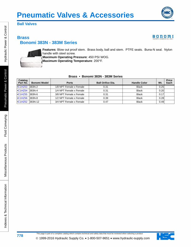
Features: Blow out proof stem. Brass body, ball and stem. PTFE seats. Buna-N seal. Nylon handle with steel screw. Maximum Operating Pressure: 450 PSI WOG. Maximum Operating Temperature: 200°F.
Brass • Bonomi 383N - 383M SeriesCatalog Part No. Bonomi Model Ports Ball Orifice Dia. Handle Color Wt.
Price Each
•C1HZ53 383N-2 1/8 NPT Female x Female 0.31 Black 0.25
•C1HZ54 383N-4 1/4 NPT Female x Female 0.31 Black 0.20
•C1HZ55 383N-6 3/8 NPT Female x Female 0.31 Black 0.17
•C1HZ56 383N-8 1/2 NPT Female x Female 0.39 Black 0.28
•C1HZ52 383N-12 3/4 NPT Female x Female 0.47 Black 0.49
Ball Valves
This page is part of a complete catalog which contains technical and safety data that must be reviewed when selecting a product
Pneumatic Valves & Accessories
Hydraulic P
ower &
Control
Pneum
atic Pow
er & C
ontrolF
luid Conveying
Miscellaneous P
roductsIndexes &
Technical Information
779 1999-2016 Hydraulic Supply Co. • 1-800-507-9651 • www.hydraulic-supply.com
3-Way Palm Button Pneumatic Valves Aro® 460 Series • To 7.5 SCFM
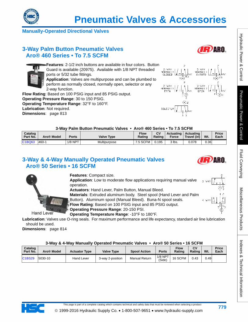
Features: 2-1/2 inch buttons are available in four colors. Button Guard is available (20975). Available with 1/8 NPT threaded ports or 5/32 tube fittings. Application: Valves are multipurpose and can be plumbed to perform as normally closed, normally open, selector or any 2-way function.
Flow Rating: Based on 100 PSIG input and 85 PSIG output. Operating Pressure Range: 30 to 150 PSIG. Operating Temperature Range: 32°F to 160°F. Lubrication: Not required. Dimensions: page 813
3-Way Palm Button Pneumatic Valves • Aro® 460 Series • To 7.5 SCFMCatalog Part No. Aro® Model Ports Valve Type
Flow Rating
CV Rating
Actuating Force
Actuating Travel (in) Wt.
Price Each
C1BQ63 460-1 1/8 NPT Multipurpose 7.5 SCFM 0.195 3 lbs. 0.078 0.36
3-Way & 4-Way Manually Operated Pneumatic Valves Aro® 50 Series • 16 SCFM
Features: Compact size. Application: Low to moderate flow applications requiring manual valve operation. Actuators: Hand Lever, Palm Button, Manual Bleed. Materials: Extruded aluminum body. Steel spool (Hand Lever and Palm Button). Aluminum spool (Manual Bleed). Buna-N spool seals. Flow Rating: Based on 100 PSIG input and 85 PSIG output. Operating Pressure Range: 20-150 PSI. Operating Temperature Range: -10°F to 180°F.
Lubrication: Valves use O-ring seals. For maximum performance and life expectancy, standard air line lubrication should be used.
Dimensions: page 814
3-Way & 4-Way Manually Operated Pneumatic Valves • Aro® 50 Series • 16 SCFMCatalog Part No. Aro® Model Actuator Type Valve Type Spool Action Ports
Flow Rating
CV Rating Wt.
Price Each
C1BS29 5030-10 Hand Lever 3-way 2-position Manual Return 1/8 NPT (Side) 16 SCFM 0.43 0.49
Manually-Operated Directional Valves
This page is part of a complete catalog which contains technical and safety data that must be reviewed when selecting a product
Pneumatic Valves & Accessories
Hyd
raul
ic P
ower
& C
ontr
olP
neum
atic
Pow
er &
Con
trol
Flu
id C
onve
ying
Mis
cella
neou
s P
rodu
cts
Inde
xes
& T
echn
ical
Info
rmat
ion
780 1999-2016 Hydraulic Supply Co. • 1-800-507-9651 • www.hydraulic-supply.com
3-Way & 4-Way Manually Operated Pneumatic Valves Aro® E Series • 26 SCFM
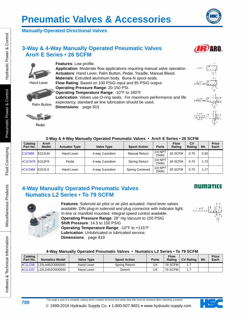
Features: Low profile. Application: Moderate flow applications requiring manual valve operation. Actuators: Hand Lever, Palm Button, Pedal, Treadle, Manual Bleed. Materials: Extruded aluminum body. Buna-N spool seals. Flow Rating: Based on 100 PSIG input and 85 PSIG output. Operating Pressure Range: 20-150 PSI. Operating Temperature Range: -10°F to 180°F. Lubrication: Valves use O-ring seals. For maximum performance and life expectancy, standard air line lubrication should be used. Dimensions: page 815
3-Way & 4-Way Manually Operated Pneumatic Valves • Aro® E Series • 26 SCFMCatalog Part No.
Aro® Model Actuator Type Valve Type Spool Action Ports
Flow Rating
CV Rating Wt.
Price Each
C1CN80 E212LM Hand Lever 4-way 2-position Manual Return 1/4 NPT (Side) 26 SCFM 0.70 0.92
•C1CN79 E212FS Pedal 4-way 2-position Spring Return 1/4 NPT (Side) 26 SCFM 0.70 1.72
•C1CN84 E312LS Hand Lever 4-way 3-position Spring Centered 1/4 NPT (Side) 26 SCFM 0.70 1.17
4-Way Manually Operated Pneumatic Valves Numatics L2 Series • To 79 SCFM
Features: Solenoid air pilot or air pilot actuated. Hand-lever valves available. DIN plug-in solenoid and plug connector with indicator light. In-line or manifold mounted. Integral speed control available. Operating Pressure Range: 28" Hg Vacuum to 150 PSIG Shift Pressure: 14.5 to 150 PSIG Operating Temperature Range: -10°F to +115°F Lubrication: Unlubricated or lubricated service. Dimensions: page 819
4-Way Manually Operated Pneumatic Valves • Numatics L2 Series • To 79 SCFMCatalog Part No. Numatics Model Valve Type Spool Action Ports
Flow Rating CV Rating Wt.
Price Each
•C1LC66 L22LA452O000000 Hand Lever Spring Return 1/4 79 SCFM 1.7
•C1LC67 L22LD452O000000 Hand Lever Detent 1/4 79 SCFM 1.7
Manually-Operated Directional Valves
This page is part of a complete catalog which contains technical and safety data that must be reviewed when selecting a product
Pneumatic Valves & Accessories
Hydraulic P
ower &
Control
Pneum
atic Pow
er & C
ontrolF
luid Conveying
Miscellaneous P
roductsIndexes &
Technical Information
781 1999-2016 Hydraulic Supply Co. • 1-800-507-9651 • www.hydraulic-supply.com
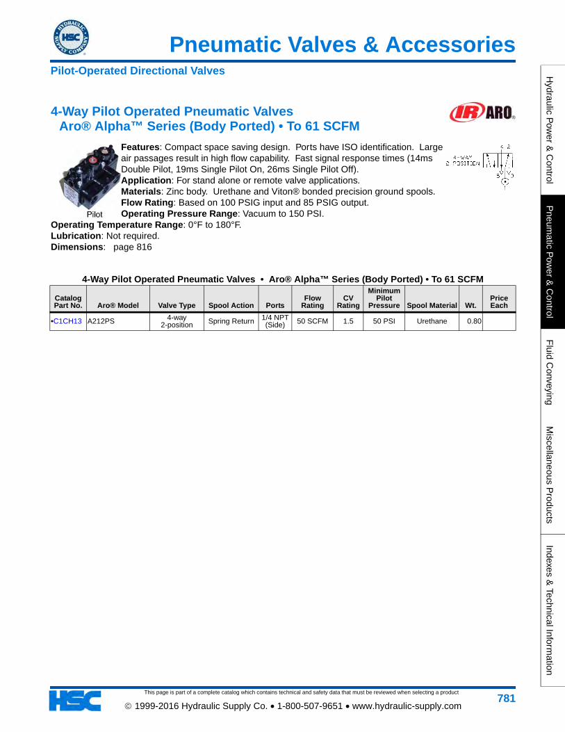
4-Way Pilot Operated Pneumatic Valves Aro® Alpha™ Series (Body Ported) • To 61 SCFM
Features: Compact space saving design. Ports have ISO identification. Large air passages result in high flow capability. Fast signal response times (14ms Double Pilot, 19ms Single Pilot On, 26ms Single Pilot Off). Application: For stand alone or remote valve applications. Materials: Zinc body. Urethane and Viton® bonded precision ground spools. Flow Rating: Based on 100 PSIG input and 85 PSIG output. Operating Pressure Range: Vacuum to 150 PSI.
Operating Temperature Range: 0°F to 180°F. Lubrication: Not required. Dimensions: page 816
4-Way Pilot Operated Pneumatic Valves • Aro® Alpha™ Series (Body Ported) • To 61 SCFM
Catalog Part No. Aro® Model Valve Type Spool Action Ports
Flow Rating
CV Rating
Minimum Pilot
Pressure Spool Material Wt.Price Each
•C1CH13 A212PS 4-way 2-position Spring Return 1/4 NPT
(Side) 50 SCFM 1.5 50 PSI Urethane 0.80
Pilot-Operated Directional Valves
This page is part of a complete catalog which contains technical and safety data that must be reviewed when selecting a product
Pneumatic Valves & Accessories
Hyd
raul
ic P
ower
& C
ontr
olP
neum
atic
Pow
er &
Con
trol
Flu
id C
onve
ying
Mis
cella
neou
s P
rodu
cts
Inde
xes
& T
echn
ical
Info
rmat
ion
782 1999-2016 Hydraulic Supply Co. • 1-800-507-9651 • www.hydraulic-supply.com
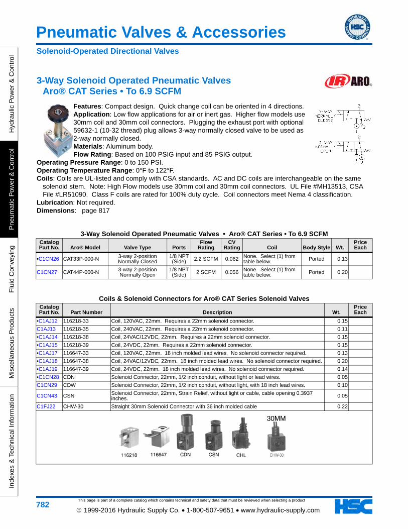
3-Way Solenoid Operated Pneumatic Valves Aro® CAT Series • To 6.9 SCFM
Features: Compact design. Quick change coil can be oriented in 4 directions. Application: Low flow applications for air or inert gas. Higher flow models use 30mm coil and 30mm coil connectors. Plugging the exhaust port with optional 59632-1 (10-32 thread) plug allows 3-way normally closed valve to be used as 2-way normally closed. Materials: Aluminum body. Flow Rating: Based on 100 PSIG input and 85 PSIG output.
Operating Pressure Range: 0 to 150 PSI. Operating Temperature Range: 0°F to 122°F. Coils: Coils are UL-listed and comply with CSA standards. AC and DC coils are interchangeable on the same
solenoid stem. Note: High Flow models use 30mm coil and 30mm coil connectors. UL File #MH13513, CSA File #LR51090. Class F coils are rated for 100% duty cycle. Coil connectors meet Nema 4 classification.
Lubrication: Not required. Dimensions: page 817
3-Way Solenoid Operated Pneumatic Valves • Aro® CAT Series • To 6.9 SCFMCatalog Part No. Aro® Model Valve Type Ports
Flow Rating
CV Rating Coil Body Style Wt.
Price Each
•C1CN26 CAT33P-000-N 3-way 2-position Normally Closed
1/8 NPT (Side) 2.2 SCFM 0.062 None. Select (1) from
table below. Ported 0.13
C1CN27 CAT44P-000-N 3-way 2-position Normally Open
1/8 NPT (Side) 2 SCFM 0.056 None. Select (1) from
table below. Ported 0.20
Coils & Solenoid Connectors for Aro® CAT Series Solenoid ValvesCatalog Part No. Part Number Description Wt.
Price Each
•C1AJ12 116218-33 Coil, 120VAC, 22mm. Requires a 22mm solenoid connector. 0.15
C1AJ13 116218-35 Coil, 240VAC, 22mm. Requires a 22mm solenoid connector. 0.11
•C1AJ14 116218-38 Coil, 24VAC/12VDC, 22mm. Requires a 22mm solenoid connector. 0.15
•C1AJ15 116218-39 Coil, 24VDC, 22mm. Requires a 22mm solenoid connector. 0.15
•C1AJ17 116647-33 Coil, 120VAC, 22mm. 18 inch molded lead wires. No solenoid connector required. 0.13
•C1AJ18 116647-38 Coil, 24VAC/12VDC, 22mm. 18 inch molded lead wires. No solenoid connector required. 0.20
•C1AJ19 116647-39 Coil, 24VDC, 22mm. 18 inch molded lead wires. No solenoid connector required. 0.14
•C1CN28 CDN Solenoid Connector, 22mm, 1/2 inch conduit, without light or lead wires. 0.05
C1CN29 CDW Solenoid Connector, 22mm, 1/2 inch conduit, without light, with 18 inch lead wires. 0.10
C1CN43 CSN Solenoid Connector, 22mm, Strain Relief, without light or cable, cable opening 0.3937 inches. 0.05
C1FJ22 CHW-30 Straight 30mm Solenoid Connector with 36 inch molded cable 0.22
Solenoid-Operated Directional Valves
This page is part of a complete catalog which contains technical and safety data that must be reviewed when selecting a product
Pneumatic Valves & Accessories
Hydraulic P
ower &
Control
Pneum
atic Pow
er & C
ontrolF
luid Conveying
Miscellaneous P
roductsIndexes &
Technical Information
783 1999-2016 Hydraulic Supply Co. • 1-800-507-9651 • www.hydraulic-supply.com
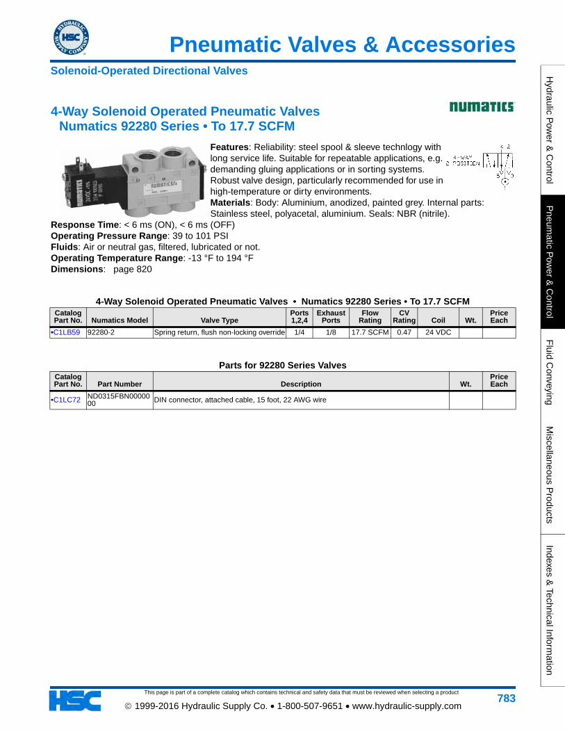
4-Way Solenoid Operated Pneumatic Valves Numatics 92280 Series • To 17.7 SCFM
Features: Reliability: steel spool & sleeve technlogy with long service life. Suitable for repeatable applications, e.g. demanding gluing applications or in sorting systems. Robust valve design, particularly recommended for use in high-temperature or dirty environments. Materials: Body: Aluminium, anodized, painted grey. Internal parts: Stainless steel, polyacetal, aluminium. Seals: NBR (nitrile).
Response Time: < 6 ms (ON), < 6 ms (OFF) Operating Pressure Range: 39 to 101 PSI Fluids: Air or neutral gas, filtered, lubricated or not. Operating Temperature Range: -13 °F to 194 °F Dimensions: page 820
4-Way Solenoid Operated Pneumatic Valves • Numatics 92280 Series • To 17.7 SCFMCatalog Part No. Numatics Model Valve Type
Ports 1,2,4
Exhaust Ports
Flow Rating
CV Rating Coil Wt.
Price Each
•C1LB59 92280-2 Spring return, flush non-locking override 1/4 1/8 17.7 SCFM 0.47 24 VDC
Parts for 92280 Series ValvesCatalog Part No. Part Number Description Wt.
Price Each
•C1LC72 ND0315FBN0000000 DIN connector, attached cable, 15 foot, 22 AWG wire
Solenoid-Operated Directional Valves
This page is part of a complete catalog which contains technical and safety data that must be reviewed when selecting a product
Pneumatic Valves & Accessories
Hyd
raul
ic P
ower
& C
ontr
olP
neum
atic
Pow
er &
Con
trol
Flu
id C
onve
ying
Mis
cella
neou
s P
rodu
cts
Inde
xes
& T
echn
ical
Info
rmat
ion
784 1999-2016 Hydraulic Supply Co. • 1-800-507-9651 • www.hydraulic-supply.com
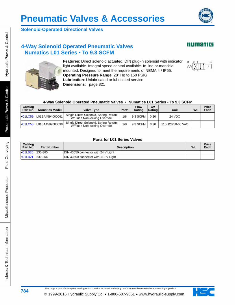
4-Way Solenoid Operated Pneumatic Valves Numatics L01 Series • To 9.3 SCFM
Features: Direct solenoid actuated. DIN plug-in solenoid with indicator light available. Integral speed control available. In-line or manifold mounted. Designed to meet the requirements of NEMA 4 / IP65. Operating Pressure Range: 28" Hg to 150 PSIG Lubrication: Unlubricated or lubricated service Dimensions: page 821
4-Way Solenoid Operated Pneumatic Valves • Numatics L01 Series • To 9.3 SCFMCatalog Part No. Numatics Model Valve Type Ports
Flow Rating
CV Rating Coil Wt.
Price Each
•C1LC59 L01SA4594000061 Single Direct Solenoid, Spring Return W/Flush Non-locking Override 1/8 9.3 SCFM 0.20 24 VDC
•C1LC58 L01SA4592000030 Single Direct Solenoid, Spring Return W/Flush Non-locking Override 1/8 9.3 SCFM 0.20 110-120/50-60 VAC
Parts for L01 Series ValvesCatalog Part No. Part Number Description Wt.
Price Each
•C1LB20 230-365 DIN 43650 connector with 24 V Light
•C1LB21 230-366 DIN 43650 connector with 110 V Light
Solenoid-Operated Directional Valves
This page is part of a complete catalog which contains technical and safety data that must be reviewed when selecting a product
Pneumatic Valves & Accessories
Hydraulic P
ower &
Control
Pneum
atic Pow
er & C
ontrolF
luid Conveying
Miscellaneous P
roductsIndexes &
Technical Information
785 1999-2016 Hydraulic Supply Co. • 1-800-507-9651 • www.hydraulic-supply.com
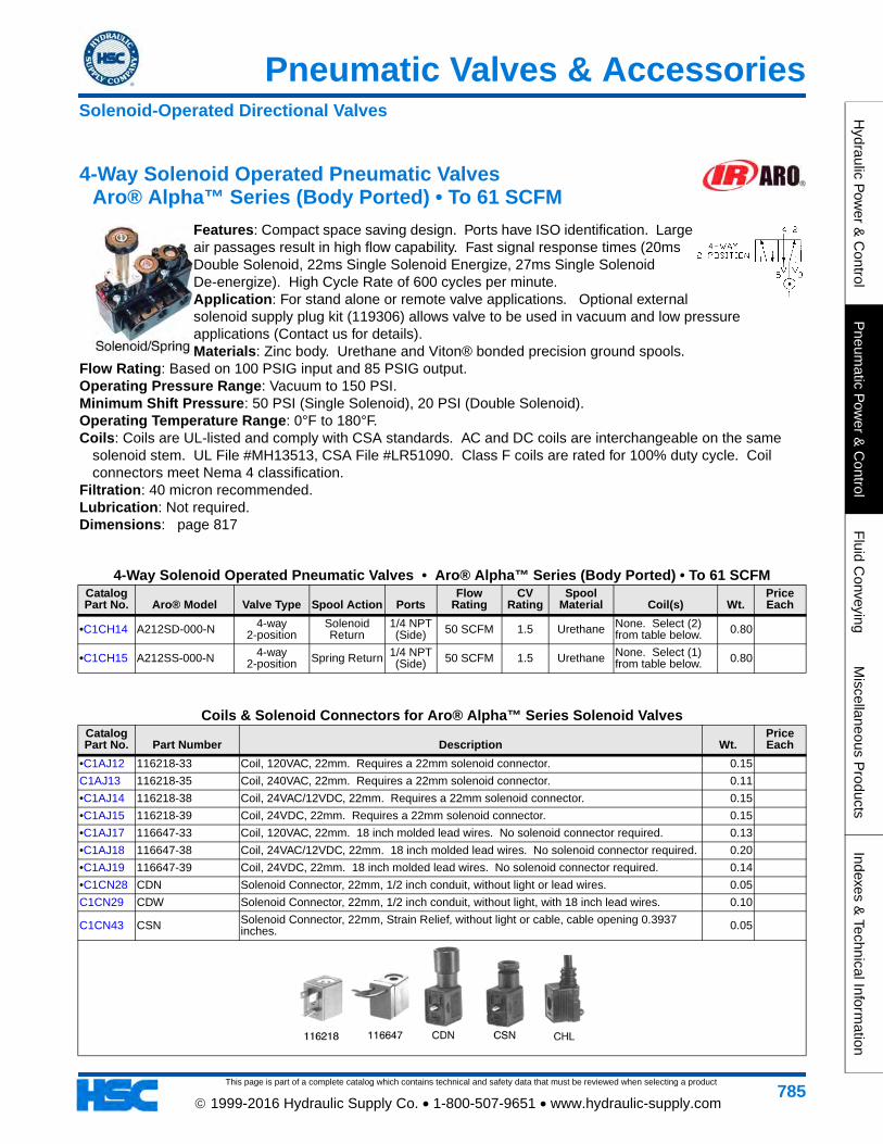
4-Way Solenoid Operated Pneumatic Valves Aro® Alpha™ Series (Body Ported) • To 61 SCFM
Features: Compact space saving design. Ports have ISO identification. Large air passages result in high flow capability. Fast signal response times (20ms Double Solenoid, 22ms Single Solenoid Energize, 27ms Single Solenoid De-energize). High Cycle Rate of 600 cycles per minute. Application: For stand alone or remote valve applications. Optional external solenoid supply plug kit (119306) allows valve to be used in vacuum and low pressure applications (Contact us for details). Materials: Zinc body. Urethane and Viton® bonded precision ground spools.
Flow Rating: Based on 100 PSIG input and 85 PSIG output. Operating Pressure Range: Vacuum to 150 PSI. Minimum Shift Pressure: 50 PSI (Single Solenoid), 20 PSI (Double Solenoid). Operating Temperature Range: 0°F to 180°F. Coils: Coils are UL-listed and comply with CSA standards. AC and DC coils are interchangeable on the same
solenoid stem. UL File #MH13513, CSA File #LR51090. Class F coils are rated for 100% duty cycle. Coil connectors meet Nema 4 classification.
Filtration: 40 micron recommended. Lubrication: Not required. Dimensions: page 817
4-Way Solenoid Operated Pneumatic Valves • Aro® Alpha™ Series (Body Ported) • To 61 SCFMCatalog Part No. Aro® Model Valve Type Spool Action Ports
Flow Rating
CV Rating
Spool Material Coil(s) Wt.
Price Each
•C1CH14 A212SD-000-N 4-way 2-position
Solenoid Return
1/4 NPT (Side) 50 SCFM 1.5 Urethane None. Select (2)
from table below. 0.80
•C1CH15 A212SS-000-N 4-way 2-position Spring Return 1/4 NPT
(Side) 50 SCFM 1.5 Urethane None. Select (1) from table below. 0.80
Coils & Solenoid Connectors for Aro® Alpha™ Series Solenoid ValvesCatalog Part No. Part Number Description Wt.
Price Each
•C1AJ12 116218-33 Coil, 120VAC, 22mm. Requires a 22mm solenoid connector. 0.15
C1AJ13 116218-35 Coil, 240VAC, 22mm. Requires a 22mm solenoid connector. 0.11
•C1AJ14 116218-38 Coil, 24VAC/12VDC, 22mm. Requires a 22mm solenoid connector. 0.15
•C1AJ15 116218-39 Coil, 24VDC, 22mm. Requires a 22mm solenoid connector. 0.15
•C1AJ17 116647-33 Coil, 120VAC, 22mm. 18 inch molded lead wires. No solenoid connector required. 0.13
•C1AJ18 116647-38 Coil, 24VAC/12VDC, 22mm. 18 inch molded lead wires. No solenoid connector required. 0.20
•C1AJ19 116647-39 Coil, 24VDC, 22mm. 18 inch molded lead wires. No solenoid connector required. 0.14
•C1CN28 CDN Solenoid Connector, 22mm, 1/2 inch conduit, without light or lead wires. 0.05
C1CN29 CDW Solenoid Connector, 22mm, 1/2 inch conduit, without light, with 18 inch lead wires. 0.10
C1CN43 CSN Solenoid Connector, 22mm, Strain Relief, without light or cable, cable opening 0.3937 inches. 0.05
Solenoid-Operated Directional Valves
This page is part of a complete catalog which contains technical and safety data that must be reviewed when selecting a product
Pneumatic Valves & Accessories
Hyd
raul
ic P
ower
& C
ontr
olP
neum
atic
Pow
er &
Con
trol
Flu
id C
onve
ying
Mis
cella
neou
s P
rodu
cts
Inde
xes
& T
echn
ical
Info
rmat
ion
786 1999-2016 Hydraulic Supply Co. • 1-800-507-9651 • www.hydraulic-supply.com
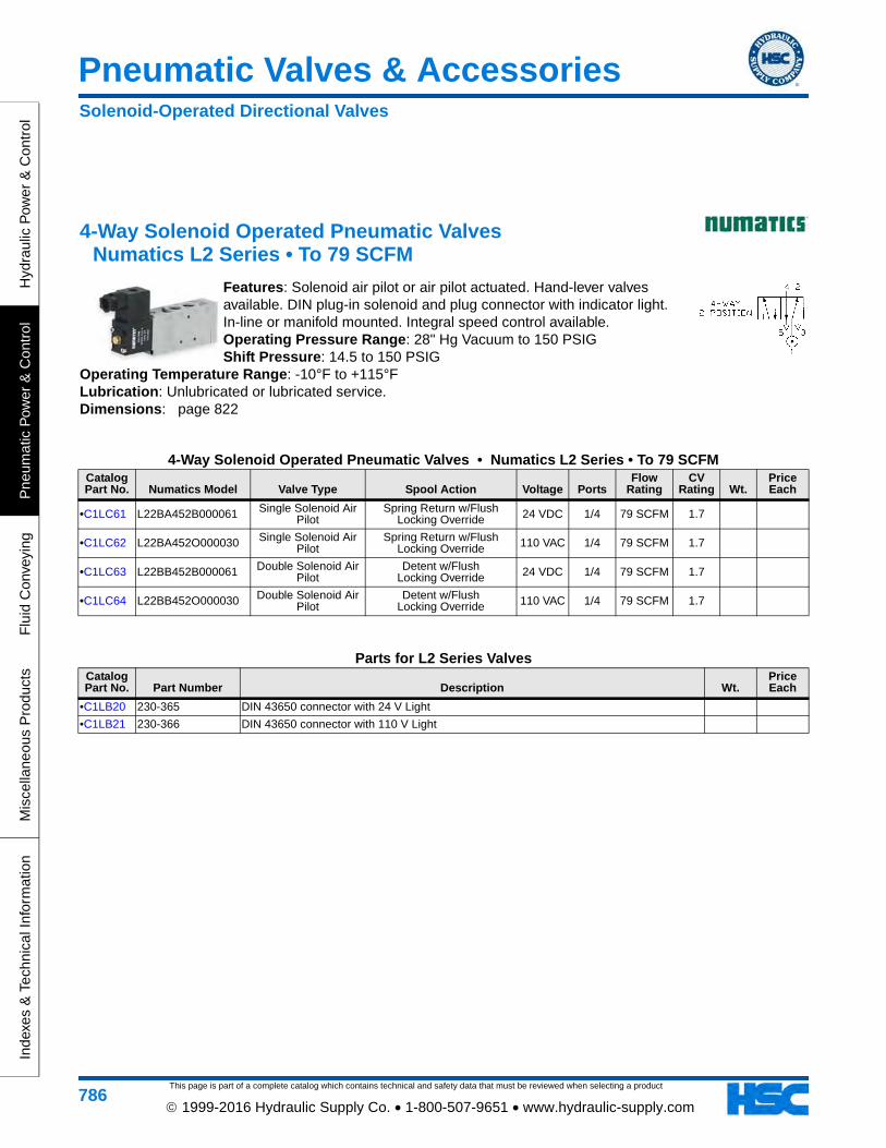
4-Way Solenoid Operated Pneumatic Valves Numatics L2 Series • To 79 SCFM
Features: Solenoid air pilot or air pilot actuated. Hand-lever valves available. DIN plug-in solenoid and plug connector with indicator light. In-line or manifold mounted. Integral speed control available. Operating Pressure Range: 28" Hg Vacuum to 150 PSIG Shift Pressure: 14.5 to 150 PSIG
Operating Temperature Range: -10°F to +115°F Lubrication: Unlubricated or lubricated service. Dimensions: page 822
4-Way Solenoid Operated Pneumatic Valves • Numatics L2 Series • To 79 SCFMCatalog Part No. Numatics Model Valve Type Spool Action Voltage Ports
Flow Rating
CV Rating Wt.
Price Each
•C1LC61 L22BA452B000061 Single Solenoid Air Pilot
Spring Return w/Flush Locking Override 24 VDC 1/4 79 SCFM 1.7
•C1LC62 L22BA452O000030 Single Solenoid Air Pilot
Spring Return w/Flush Locking Override 110 VAC 1/4 79 SCFM 1.7
•C1LC63 L22BB452B000061 Double Solenoid Air Pilot
Detent w/FlushLocking Override 24 VDC 1/4 79 SCFM 1.7
•C1LC64 L22BB452O000030 Double Solenoid Air Pilot
Detent w/FlushLocking Override 110 VAC 1/4 79 SCFM 1.7
Parts for L2 Series ValvesCatalog Part No. Part Number Description Wt.
Price Each
•C1LB20 230-365 DIN 43650 connector with 24 V Light
•C1LB21 230-366 DIN 43650 connector with 110 V Light
Solenoid-Operated Directional Valves
This page is part of a complete catalog which contains technical and safety data that must be reviewed when selecting a product
Pneumatic Valves & Accessories
Hydraulic P
ower &
Control
Pneum
atic Pow
er & C
ontrolF
luid Conveying
Miscellaneous P
roductsIndexes &
Technical Information
787 1999-2016 Hydraulic Supply Co. • 1-800-507-9651 • www.hydraulic-supply.com
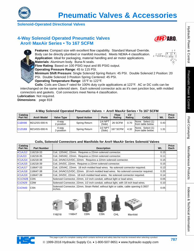
4-Way Solenoid Operated Pneumatic Valves Aro® MaxAir Series • To 167 SCFM
Features: Compact size with excellent flow capability. Standard Manual Override. Body can be directly plumbed or manifold mounted. Meets NEMA-4 classification. Application: Ideal for packaging, material handling and air motor applications. Materials: Aluminum body. Buna-N seals. Flow Rating: Based on 100 PSIG input and 85 PSIG output. Operating Pressure Range: 45 to 115 PSI. Minimum Shift Pressure: Single Solenoid Spring Return: 45 PSI. Double Solenoid 2 Position: 20 PSI. Double Solenoid 3 Position Spring Centered: 45 PSI. Operating Temperature Range: 15°F to 122°F. Coils: Coils are Class F rated for 100% duty cycle applications at 122°F. AC or DC coils can be
interchanged on the same solenoid stem. Each solenoid connector acts as it's own junction box, with molded connectors and gaskets. Coil connectors meet Nema 4 classification.
Lubrication: Not required. Dimensions: page 818
4-Way Solenoid Operated Pneumatic Valves • Aro® MaxAir Series • To 167 SCFMCatalog Part No. Aro® Model Valve Type Spool Action Ports
Flow Rating
CV Rating Coil(s) Wt.
Price Each
C1EK66 M212SS-000-N 4-way 2-position Spring Return 1/4 NPT
(Side) 26 SCFM 0.70 None. Select (1) from table below. 0.43
C1ZU69 M214SS-000-N 4-way 2-position Spring Return 1/2 NPT
(Side) 167 SCFM 4.32 None. Select (1) from table below. 1.31
Coils, Solenoid Connectors and Manifolds for Aro® MaxAir Series Solenoid ValvesCatalog Part No. Part Number Description Wt.
Price Each
•C1AJ12 116218-33 Coil, 120VAC, 22mm. Requires a 22mm solenoid connector. 0.15
C1AJ13 116218-35 Coil, 240VAC, 22mm. Requires a 22mm solenoid connector. 0.11
•C1AJ14 116218-38 Coil, 24VAC/12VDC, 22mm. Requires a 22mm solenoid connector. 0.15
•C1AJ15 116218-39 Coil, 24VDC, 22mm. Requires a 22mm solenoid connector. 0.15
•C1AJ17 116647-33 Coil, 120VAC, 22mm. 18 inch molded lead wires. No solenoid connector required. 0.13
•C1AJ18 116647-38 Coil, 24VAC/12VDC, 22mm. 18 inch molded lead wires. No solenoid connector required. 0.20
•C1AJ19 116647-39 Coil, 24VDC, 22mm. 18 inch molded lead wires. No solenoid connector required. 0.14
•C1CN28 CDN Solenoid Connector, 22mm, 1/2 inch conduit, without light or lead wires. 0.05
C1CN29 CDW Solenoid Connector, 22mm, 1/2 inch conduit, without light, with 18 inch lead wires. 0.10
C1CN43 CSN Solenoid Connector, 22mm, Strain Relief, without light or cable, cable opening 0.3937 inches. 0.05
Solenoid-Operated Directional Valves
This page is part of a complete catalog which contains technical and safety data that must be reviewed when selecting a product
Pneumatic Valves & Accessories
Hyd
raul
ic P
ower
& C
ontr
olP
neum
atic
Pow
er &
Con
trol
Flu
id C
onve
ying
Mis
cella
neou
s P
rodu
cts
Inde
xes
& T
echn
ical
Info
rmat
ion
788 1999-2016 Hydraulic Supply Co. • 1-800-507-9651 • www.hydraulic-supply.com
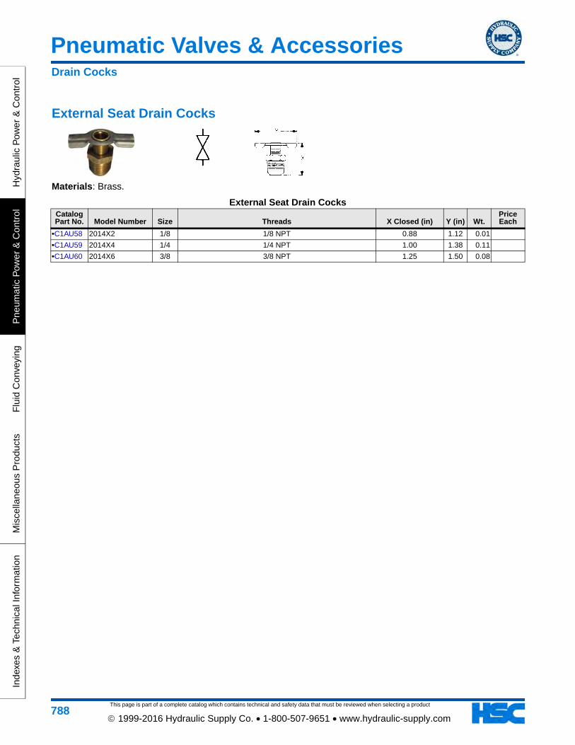
External Seat Drain Cocks
Materials: Brass.
External Seat Drain CocksCatalog Part No. Model Number Size Threads X Closed (in) Y (in) Wt.
Price Each
•C1AU58 2014X2 1/8 1/8 NPT 0.88 1.12 0.01
•C1AU59 2014X4 1/4 1/4 NPT 1.00 1.38 0.11
•C1AU60 2014X6 3/8 3/8 NPT 1.25 1.50 0.08
Drain Cocks
This page is part of a complete catalog which contains technical and safety data that must be reviewed when selecting a product
Pneumatic Valves & Accessories
Hydraulic P
ower &
Control
Pneum
atic Pow
er & C
ontrolF
luid Conveying
Miscellaneous P
roductsIndexes &
Technical Information
789 1999-2016 Hydraulic Supply Co. • 1-800-507-9651 • www.hydraulic-supply.com
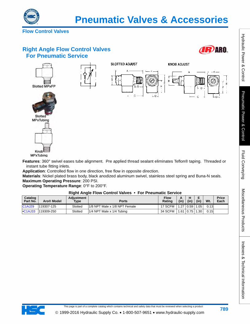
Right Angle Flow Control Valves For Pneumatic Service
Features: 360° swivel eases tube alignment. Pre applied thread sealant eliminates Teflon® taping. Threaded or instant tube fitting inlets.
Application: Controlled flow in one direction, free flow in opposite direction. Materials: Nickel plated brass body, black anodized aluminum swivel, stainless steel spring and Buna-N seals. Maximum Operating Pressure: 200 PSI. Operating Temperature Range: 0°F to 200°F.
Right Angle Flow Control Valves • For Pneumatic ServiceCatalog Part No. Aro® Model
Adjustment Type Ports
Flow Rating
A (in)
H (in)
E (in) Wt.
Price Each
C1AJ29 119307-125 Slotted 1/8 NPT Male x 1/8 NPT Female 17 SCFM 1.27 0.59 1.05 0.13
•C1AJ33 119309-250 Slotted 1/4 NPT Male x 1/4 Tubing 34 SCFM 1.61 0.75 1.30 0.15
Flow Control Valves
This page is part of a complete catalog which contains technical and safety data that must be reviewed when selecting a product
Pneumatic Valves & Accessories
Hyd
raul
ic P
ower
& C
ontr
olP
neum
atic
Pow
er &
Con
trol
Flu
id C
onve
ying
Mis
cella
neou
s P
rodu
cts
Inde
xes
& T
echn
ical
Info
rmat
ion
790 1999-2016 Hydraulic Supply Co. • 1-800-507-9651 • www.hydraulic-supply.com
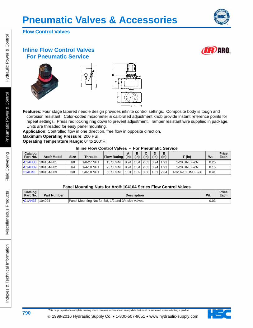
Inline Flow Control Valves For Pneumatic Service
Features: Four stage tapered needle design provides infinite control settings. Composite body is tough and corrosion resistant. Color-coded micrometer & calibrated adjustment knob provide instant reference points for repeat settings. Press red locking ring down to prevent adjustment. Tamper resistant wire supplied in package. Units are threaded for easy panel mounting.
Application: Controlled flow in one direction, free flow in opposite direction. Maximum Operating Pressure: 200 PSI. Operating Temperature Range: 0° to 200°F.
Inline Flow Control Valves • For Pneumatic ServiceCatalog Part No. Aro® Model Size Threads Flow Rating
A (in)
B (in)
C (in)
D (in)
E (in) F (in) Wt.
Price Each
•C1AH38 104104-F01 1/8 1/8-27 NPT 15 SCFM 0.94 1.34 2.83 0.94 1.91 1-20 UNEF-2A 0.25
•C1AH39 104104-F02 1/4 1/4-18 NPT 25 SCFM 0.94 1.34 2.83 0.94 1.91 1-20 UNEF-2A 0.15
C1AH40 104104-F03 3/8 3/8-18 NPT 55 SCFM 1.31 1.69 3.86 1.31 2.84 1-3/16-18 UNEF-2A 0.41
Panel Mounting Nuts for Aro® 104104 Series Flow Control ValvesCatalog Part No. Part Number Description Wt.
Price Each
•C1AH37 104094 Panel Mounting Nut for 3/8, 1/2 and 3/4 size valves. 0.03
Flow Control Valves
This page is part of a complete catalog which contains technical and safety data that must be reviewed when selecting a product
Pneumatic Valves & Accessories
Hydraulic P
ower &
Control
Pneum
atic Pow
er & C
ontrolF
luid Conveying
Miscellaneous P
roductsIndexes &
Technical Information
791 1999-2016 Hydraulic Supply Co. • 1-800-507-9651 • www.hydraulic-supply.com
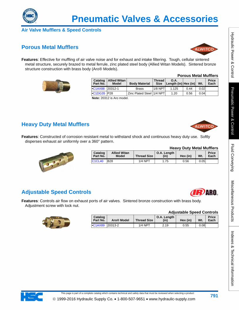
Porous Metal Mufflers
Features: Effective for muffling of air valve noise and for exhaust and intake filtering. Tough, cellular sintered metal structure, securely brazed to metal ferrule, zinc plated steel body (Allied Witan Models). Sintered bronze structure construction with brass body (Aro® Models).
Porous Metal MufflersCatalog Part No.
Allied Witan Model Body Material
Thread Size
O.A. Length (in) Hex (in) Wt.
Price Each
•C1AX88 20312-1 Brass 1/8 NPT 1.125 0.44 0.02
•C1DG35 P28 Zinc Plated Steel 1/4 NPT 1.20 0.56 0.04
Note: 20312 is Aro model.
Heavy Duty Metal Mufflers
Features: Constructed of corrosion resistant metal to withstand shock and continuous heavy duty use. Softly disperses exhaust air uniformly over a 360° pattern.
Heavy Duty Metal MufflersCatalog Part No.
Allied Witan Model Thread Size
O.A. Length (in) Hex (in) Wt.
Price Each
C1CL40 B28 1/4 NPT 1.75 0.56 0.05
Adjustable Speed Controls
Features: Controls air flow on exhaust ports of air valves. Sintered bronze construction with brass body. Adjustment screw with lock nut.
Adjustable Speed ControlsCatalog Part No. Aro® Model Thread Size
O.A. Length (in) Hex (in) Wt.
Price Each
•C1AX89 20313-2 1/4 NPT 2.19 0.55 0.08
Air Valve Mufflers & Speed Controls
This page is part of a complete catalog which contains technical and safety data that must be reviewed when selecting a product
Pneumatic Valves & Accessories
Hyd
raul
ic P
ower
& C
ontr
olP
neum
atic
Pow
er &
Con
trol
Flu
id C
onve
ying
Mis
cella
neou
s P
rodu
cts
Inde
xes
& T
echn
ical
Info
rmat
ion
792 1999-2016 Hydraulic Supply Co. • 1-800-507-9651 • www.hydraulic-supply.com
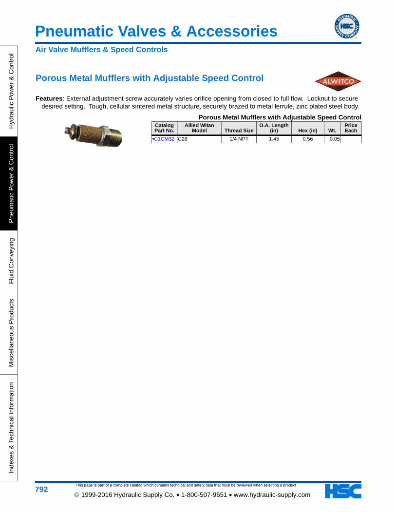
Porous Metal Mufflers with Adjustable Speed Control
Features: External adjustment screw accurately varies orifice opening from closed to full flow. Locknut to secure desired setting. Tough, cellular sintered metal structure, securely brazed to metal ferrule, zinc plated steel body.
Porous Metal Mufflers with Adjustable Speed ControlCatalog Part No.
Allied Witan Model Thread Size
O.A. Length (in) Hex (in) Wt.
Price Each
•C1CM32 C28 1/4 NPT 1.45 0.56 0.05
Air Valve Mufflers & Speed Controls
Air Line FRL's
This page is part of a complete catalog which contains technical and safety data that must be reviewed when selecting a product
Hydraulic P
ower &
Control
Pneum
atic Pow
er & C
ontrolF
luid Conveying
Miscellaneous P
roductsIndexes &
Technical Information
793 1999-2016 Hydraulic Supply Co. • 1-800-507-9651 • www.hydraulic-supply.com
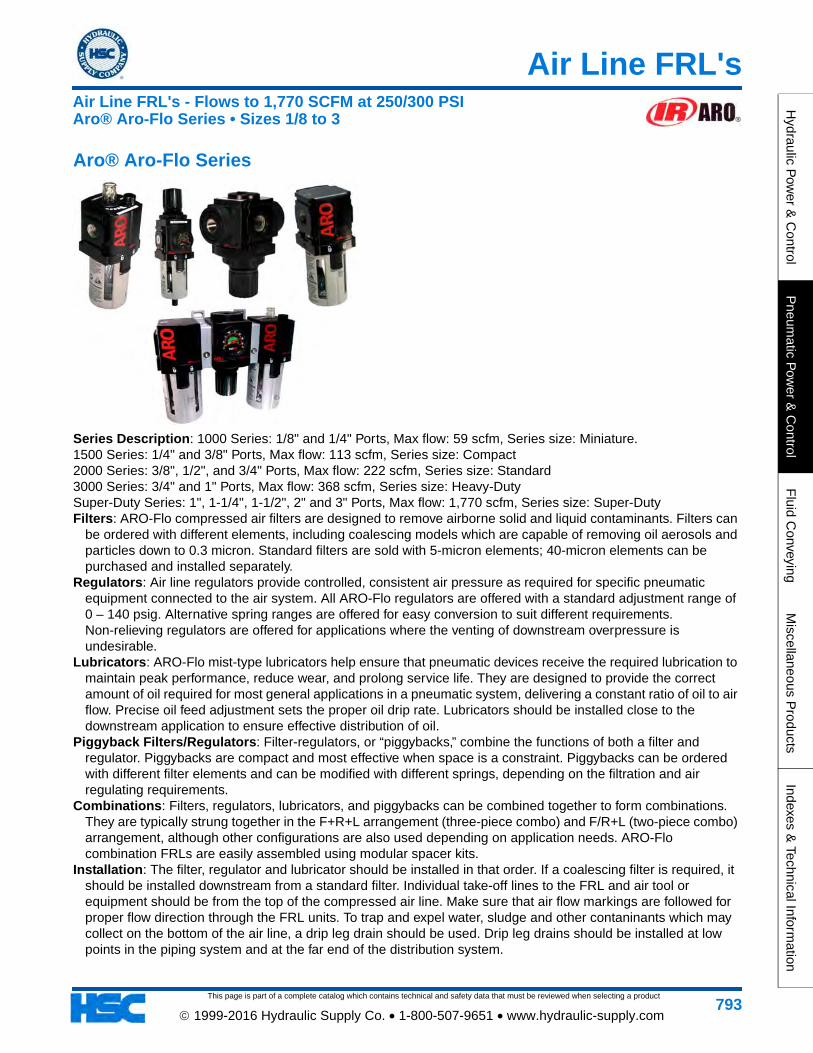
Aro® Aro-Flo Series
Series Description: 1000 Series: 1/8" and 1/4" Ports, Max flow: 59 scfm, Series size: Miniature.1500 Series: 1/4" and 3/8" Ports, Max flow: 113 scfm, Series size: Compact2000 Series: 3/8", 1/2", and 3/4" Ports, Max flow: 222 scfm, Series size: Standard3000 Series: 3/4" and 1" Ports, Max flow: 368 scfm, Series size: Heavy-DutySuper-Duty Series: 1", 1-1/4", 1-1/2", 2" and 3" Ports, Max flow: 1,770 scfm, Series size: Super-DutyFilters: ARO-Flo compressed air filters are designed to remove airborne solid and liquid contaminants. Filters can
be ordered with different elements, including coalescing models which are capable of removing oil aerosols and particles down to 0.3 micron. Standard filters are sold with 5-micron elements; 40-micron elements can be purchased and installed separately.
Regulators: Air line regulators provide controlled, consistent air pressure as required for specific pneumatic equipment connected to the air system. All ARO-Flo regulators are offered with a standard adjustment range of 0 – 140 psig. Alternative spring ranges are offered for easy conversion to suit different requirements. Non-relieving regulators are offered for applications where the venting of downstream overpressure is undesirable.
Lubricators: ARO-Flo mist-type lubricators help ensure that pneumatic devices receive the required lubrication to maintain peak performance, reduce wear, and prolong service life. They are designed to provide the correct amount of oil required for most general applications in a pneumatic system, delivering a constant ratio of oil to air flow. Precise oil feed adjustment sets the proper oil drip rate. Lubricators should be installed close to the downstream application to ensure effective distribution of oil.
Piggyback Filters/Regulators: Filter-regulators, or “piggybacks,” combine the functions of both a filter and regulator. Piggybacks are compact and most effective when space is a constraint. Piggybacks can be ordered with different filter elements and can be modified with different springs, depending on the filtration and air regulating requirements.
Combinations: Filters, regulators, lubricators, and piggybacks can be combined together to form combinations. They are typically strung together in the F+R+L arrangement (three-piece combo) and F/R+L (two-piece combo) arrangement, although other configurations are also used depending on application needs. ARO-Flo combination FRLs are easily assembled using modular spacer kits.
Installation: The filter, regulator and lubricator should be installed in that order. If a coalescing filter is required, it should be installed downstream from a standard filter. Individual take-off lines to the FRL and air tool or equipment should be from the top of the compressed air line. Make sure that air flow markings are followed for proper flow direction through the FRL units. To trap and expel water, sludge and other contaninants which may collect on the bottom of the air line, a drip leg drain should be used. Drip leg drains should be installed at low points in the piping system and at the far end of the distribution system.
Air Line FRL's - Flows to 1,770 SCFM at 250/300 PSIAro® Aro-Flo Series • Sizes 1/8 to 3
This page is part of a complete catalog which contains technical and safety data that must be reviewed when selecting a product
Air Line FRL's
Hyd
raul
ic P
ower
& C
ontr
olP
neum
atic
Pow
er &
Con
trol
Flu
id C
onve
ying
Mis
cella
neou
s P
rodu
cts
Inde
xes
& T
echn
ical
Info
rmat
ion
794 1999-2016 Hydraulic Supply Co. • 1-800-507-9651 • www.hydraulic-supply.com
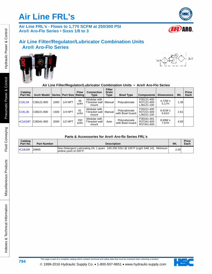
Air Line Filter/Regulator/Lubricator Combination Units Aro® Aro-Flo Series
Air Line Filter/Regulator/Lubricator Combination Units • Aro® Aro-Flo Series
Catalog Part No. Aro® Model Series Port Size
Flow Rating
Connection Type
Filter Drain Type Bowl Type Components Dimensions Wt.
Price Each
C1KL34 C38121-800 1000 1/4 NPT 46 scfm
Modular with T-bracket wall
mountManual Polycabonate
F35121-400 R37121-600 L36121-100
4.72W x 5.17H 1.35
C1KL35 C38221-800 1500 1/4 NPT 61 scfm
Modular with T-bracket wall
mountManual Polycabonate
with Bowl Guard
F35221-400 R37221-600 L36221-100
6.61W x 6.61H 2.61
•C1KG87 C38341-800 2000 1/2 NPT 150 scfm
Modular with T-bracket wall
mountAuto Polycabonate
with Bowl Guard
F35341-401 R37341-600 R37341-600
8.69W x 7.67H 4.83
Parts & Accessories for Aro® Aro-flo Series FRL'sCatalog Part No. Part Number Description Wt.
Price Each
•C1BJ99 29665 Non-Detergent Lubricating Oil, 1 quart. 100-200 SSU @ 100°F (Light SAE 10). Minimum aniline point of 200°F. 2.00
Air Line FRL's - Flows to 1,770 SCFM at 250/300 PSIAro® Aro-Flo Series • Sizes 1/8 to 3
Air Line FRL's
This page is part of a complete catalog which contains technical and safety data that must be reviewed when selecting a product
Hydraulic P
ower &
Control
Pneum
atic Pow
er & C
ontrolF
luid Conveying
Miscellaneous P
roductsIndexes &
Technical Information
795 1999-2016 Hydraulic Supply Co. • 1-800-507-9651 • www.hydraulic-supply.com
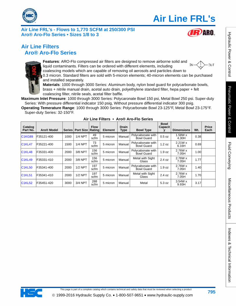
Air Line Filters Aro® Aro-Flo Series
Features: ARO-Flo compressed air filters are designed to remove airborne solid and liquid contaminants. Filters can be ordered with different elements, including coalescing models which are capable of removing oil aerosols and particles down to 0.3 micron. Standard filters are sold with 5-micron elements; 40-micron elements can be purchased and installed separately. Materials: 1000 through 3000 Series: Aluminum body, nylon bowl guard for polycarbonate bowls, brass + nitrile manual drain, acetal auto drain, polyethylene standard filter, hepa paper + felt coalescing filter, nitrile seals, acetal filter baffle.
Maximum Inlet Pressure: 1000 through 3000 Series: Polycaronate Bowl 150 psi, Metal Bowl 250 psi. Super-duty Series: With pressure differential indicator 150 psig, Without pressure differential indicator 300 psig.
Operating Temerature Range: 1000 through 3000 Series: Polycarbonate Bowl 23-125°F, Metal Bowl 23-175°F. Super-duty Series: 32-150°F.
Air Line Filters • Aro® Aro-Flo Series
Catalog Part No. Aro® Model Series Port Size
Flow Rating Element
Drain Type Bowl Type
Bowl Capacit
y Dimensions Wt.Price Each
C1KG89 F35121-400 1000 1/4 NPT 49 scfm 5 micron Manual Polycabonate with
Bowl Guard 0.5 oz 1.58W x 4.30H 0.38
C1KL47 F35221-400 1500 1/4 NPT 73 scfm 5 micron Manual Polycabonate with
Bowl Guard 1.2 oz 2.21W x 6.16H 0.69
C1KL48 F35331-400 2000 3/8 NPT 156 scfm 5 micron Manual Polycabonate with
Bowl Guard 1.9 oz 2.76W x 7.05H 1.00
C1KL49 F35331-410 2000 3/8 NPT 156 scfm 5 micron Manual Metal with Sight
Glass 2.4 oz 2.76W x 7.05H 1.77
C1KL50 F35341-400 2000 1/2 NPT 197 scfm 5 micron Manual Polycabonate with
Bowl Guard 1.9 oz 2.76W x 7.05H 1.40
C1KL51 F35341-410 2000 1/2 NPT 197 scfm 5 micron Manual Metal with Sight
Glass 2.4 oz 2.76W x 7.05H 1.70
C1KL52 F35451-420 3000 3/4 NPT 288 scfm 5 micron Manual Metal 5.3 oz 3.54W x
9.93H 3.17
Air Line FRL's - Flows to 1,770 SCFM at 250/300 PSIAro® Aro-Flo Series • Sizes 1/8 to 3
This page is part of a complete catalog which contains technical and safety data that must be reviewed when selecting a product
Air Line FRL's
Hyd
raul
ic P
ower
& C
ontr
olP
neum
atic
Pow
er &
Con
trol
Flu
id C
onve
ying
Mis
cella
neou
s P
rodu
cts
Inde
xes
& T
echn
ical
Info
rmat
ion
796 1999-2016 Hydraulic Supply Co. • 1-800-507-9651 • www.hydraulic-supply.com
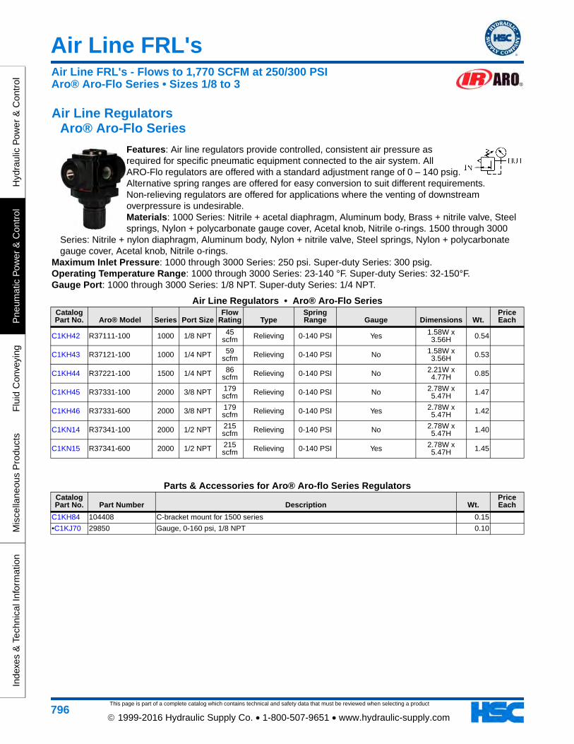
Air Line Regulators Aro® Aro-Flo Series
Features: Air line regulators provide controlled, consistent air pressure as required for specific pneumatic equipment connected to the air system. All ARO-Flo regulators are offered with a standard adjustment range of 0 – 140 psig. Alternative spring ranges are offered for easy conversion to suit different requirements. Non-relieving regulators are offered for applications where the venting of downstream overpressure is undesirable. Materials: 1000 Series: Nitrile + acetal diaphragm, Aluminum body, Brass + nitrile valve, Steel springs, Nylon + polycarbonate gauge cover, Acetal knob, Nitrile o-rings. 1500 through 3000
Series: Nitrile + nylon diaphragm, Aluminum body, Nylon + nitrile valve, Steel springs, Nylon + polycarbonate gauge cover, Acetal knob, Nitrile o-rings.
Maximum Inlet Pressure: 1000 through 3000 Series: 250 psi. Super-duty Series: 300 psig. Operating Temperature Range: 1000 through 3000 Series: 23-140 °F. Super-duty Series: 32-150°F. Gauge Port: 1000 through 3000 Series: 1/8 NPT. Super-duty Series: 1/4 NPT.
Air Line Regulators • Aro® Aro-Flo SeriesCatalog Part No. Aro® Model Series Port Size
Flow Rating Type
Spring Range Gauge Dimensions Wt.
Price Each
C1KH42 R37111-100 1000 1/8 NPT 45 scfm Relieving 0-140 PSI Yes 1.58W x
3.56H 0.54
C1KH43 R37121-100 1000 1/4 NPT 59 scfm Relieving 0-140 PSI No 1.58W x
3.56H 0.53
C1KH44 R37221-100 1500 1/4 NPT 86 scfm Relieving 0-140 PSI No 2.21W x
4.77H 0.85
C1KH45 R37331-100 2000 3/8 NPT 179 scfm Relieving 0-140 PSI No 2.78W x
5.47H 1.47
C1KH46 R37331-600 2000 3/8 NPT 179 scfm Relieving 0-140 PSI Yes 2.78W x
5.47H 1.42
C1KN14 R37341-100 2000 1/2 NPT 215 scfm Relieving 0-140 PSI No 2.78W x
5.47H 1.40
C1KN15 R37341-600 2000 1/2 NPT 215 scfm Relieving 0-140 PSI Yes 2.78W x
5.47H 1.45
Parts & Accessories for Aro® Aro-flo Series RegulatorsCatalog Part No. Part Number Description Wt.
Price Each
C1KH84 104408 C-bracket mount for 1500 series 0.15
•C1KJ70 29850 Gauge, 0-160 psi, 1/8 NPT 0.10
Air Line FRL's - Flows to 1,770 SCFM at 250/300 PSIAro® Aro-Flo Series • Sizes 1/8 to 3
Air Line FRL's
This page is part of a complete catalog which contains technical and safety data that must be reviewed when selecting a product
Hydraulic P
ower &
Control
Pneum
atic Pow
er & C
ontrolF
luid Conveying
Miscellaneous P
roductsIndexes &
Technical Information
797 1999-2016 Hydraulic Supply Co. • 1-800-507-9651 • www.hydraulic-supply.com
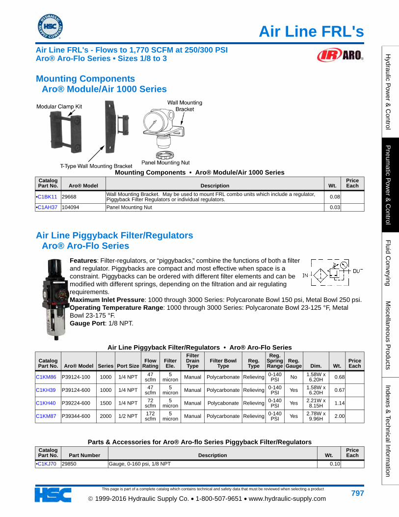
Mounting Components Aro® Module/Air 1000 Series
Mounting Components • Aro® Module/Air 1000 SeriesCatalog Part No. Aro® Model Description Wt.
Price Each
•C1BK11 29668 Wall Mounting Bracket. May be used to mount FRL combo units which include a regulator, Piggyback Filter Regulators or individual regulators. 0.08
•C1AH37 104094 Panel Mounting Nut 0.03
Air Line Piggyback Filter/Regulators Aro® Aro-Flo Series
Features: Filter-regulators, or “piggybacks,” combine the functions of both a filter and regulator. Piggybacks are compact and most effective when space is a constraint. Piggybacks can be ordered with different filter elements and can be modified with different springs, depending on the filtration and air regulating requirements. Maximum Inlet Pressure: 1000 through 3000 Series: Polycaronate Bowl 150 psi, Metal Bowl 250 psi. Operating Temperature Range: 1000 through 3000 Series: Polycaronate Bowl 23-125 °F, Metal Bowl 23-175 °F. Gauge Port: 1/8 NPT.
Air Line Piggyback Filter/Regulators • Aro® Aro-Flo Series
Catalog Part No. Aro® Model Series Port Size
Flow Rating
Filter Ele.
Filter Drain Type
Filter Bowl Type
Reg. Type
Reg. Spring Range
Reg. Gauge Dim. Wt.
Price Each
C1KM86 P39124-100 1000 1/4 NPT 47 scfm
5 micron Manual Polycarbonate Relieving 0-140
PSI No 1.58W x 6.20H 0.68
C1KH39 P39124-600 1000 1/4 NPT 47 scfm
5 micron Manual Polycarbonate Relieving 0-140
PSI Yes 1.58W x 6.20H 0.67
C1KH40 P39224-600 1500 1/4 NPT 72 scfm
5 micron Manual Polycabonate Relieving 0-140
PSI Yes 2.21W x 8.15H 1.14
C1KM87 P39344-600 2000 1/2 NPT 172 scfm
5 micron Manual Polycarbonate Relieving 0-140
PSI Yes 2.78W x 9.96H 2.00
Parts & Accessories for Aro® Aro-flo Series Piggyback Filter/RegulatorsCatalog Part No. Part Number Description Wt.
Price Each
•C1KJ70 29850 Gauge, 0-160 psi, 1/8 NPT 0.10
Air Line FRL's - Flows to 1,770 SCFM at 250/300 PSIAro® Aro-Flo Series • Sizes 1/8 to 3
This page is part of a complete catalog which contains technical and safety data that must be reviewed when selecting a product
Air Line FRL's
Hyd
raul
ic P
ower
& C
ontr
olP
neum
atic
Pow
er &
Con
trol
Flu
id C
onve
ying
Mis
cella
neou
s P
rodu
cts
Inde
xes
& T
echn
ical
Info
rmat
ion
798 1999-2016 Hydraulic Supply Co. • 1-800-507-9651 • www.hydraulic-supply.com
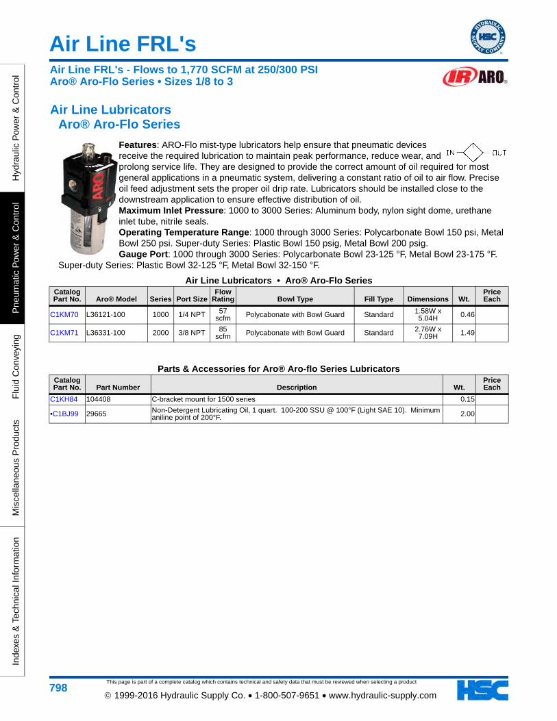
Air Line Lubricators Aro® Aro-Flo Series
Features: ARO-Flo mist-type lubricators help ensure that pneumatic devices receive the required lubrication to maintain peak performance, reduce wear, and prolong service life. They are designed to provide the correct amount of oil required for most general applications in a pneumatic system, delivering a constant ratio of oil to air flow. Precise oil feed adjustment sets the proper oil drip rate. Lubricators should be installed close to the downstream application to ensure effective distribution of oil. Maximum Inlet Pressure: 1000 to 3000 Series: Aluminum body, nylon sight dome, urethane inlet tube, nitrile seals. Operating Temperature Range: 1000 through 3000 Series: Polycarbonate Bowl 150 psi, Metal Bowl 250 psi. Super-duty Series: Plastic Bowl 150 psig, Metal Bowl 200 psig. Gauge Port: 1000 through 3000 Series: Polycarbonate Bowl 23-125 °F, Metal Bowl 23-175 °F.
Super-duty Series: Plastic Bowl 32-125 °F, Metal Bowl 32-150 °F.
Air Line Lubricators • Aro® Aro-Flo SeriesCatalog Part No. Aro® Model Series Port Size
Flow Rating Bowl Type Fill Type Dimensions Wt.
Price Each
C1KM70 L36121-100 1000 1/4 NPT 57 scfm Polycabonate with Bowl Guard Standard 1.58W x
5.04H 0.46
C1KM71 L36331-100 2000 3/8 NPT 85 scfm Polycabonate with Bowl Guard Standard 2.76W x
7.09H 1.49
Parts & Accessories for Aro® Aro-flo Series LubricatorsCatalog Part No. Part Number Description Wt.
Price Each
C1KH84 104408 C-bracket mount for 1500 series 0.15
•C1BJ99 29665 Non-Detergent Lubricating Oil, 1 quart. 100-200 SSU @ 100°F (Light SAE 10). Minimum aniline point of 200°F. 2.00
Air Line FRL's - Flows to 1,770 SCFM at 250/300 PSIAro® Aro-Flo Series • Sizes 1/8 to 3
Air Line FRL's
This page is part of a complete catalog which contains technical and safety data that must be reviewed when selecting a product
Hydraulic P
ower &
Control
Pneum
atic Pow
er & C
ontrolF
luid Conveying
Miscellaneous P
roductsIndexes &
Technical Information
799 1999-2016 Hydraulic Supply Co. • 1-800-507-9651 • www.hydraulic-supply.com
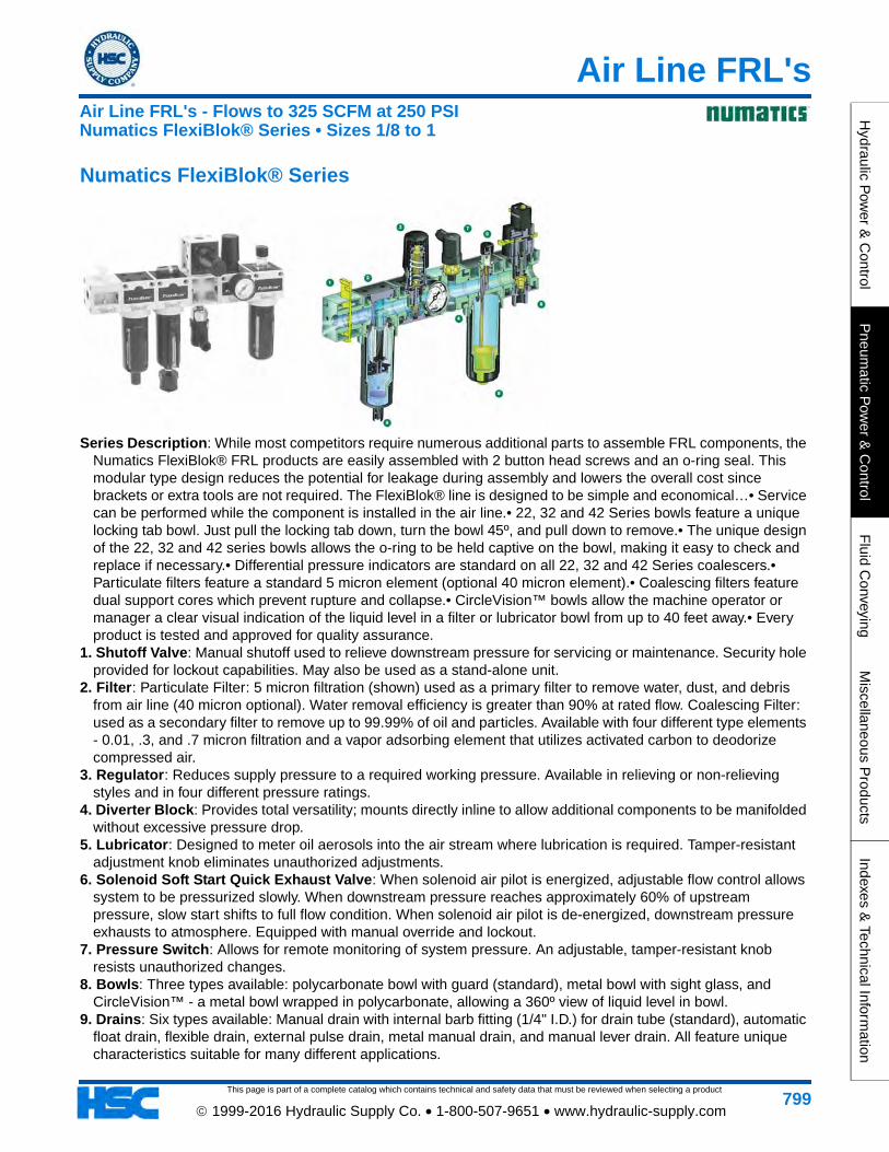
Numatics FlexiBlok® Series
Series Description: While most competitors require numerous additional parts to assemble FRL components, the Numatics FlexiBlok® FRL products are easily assembled with 2 button head screws and an o-ring seal. This modular type design reduces the potential for leakage during assembly and lowers the overall cost since brackets or extra tools are not required. The FlexiBlok® line is designed to be simple and economical…• Service can be performed while the component is installed in the air line.• 22, 32 and 42 Series bowls feature a unique locking tab bowl. Just pull the locking tab down, turn the bowl 45º, and pull down to remove.• The unique design of the 22, 32 and 42 series bowls allows the o-ring to be held captive on the bowl, making it easy to check and replace if necessary.• Differential pressure indicators are standard on all 22, 32 and 42 Series coalescers.• Particulate filters feature a standard 5 micron element (optional 40 micron element).• Coalescing filters feature dual support cores which prevent rupture and collapse.• CircleVision™ bowls allow the machine operator or manager a clear visual indication of the liquid level in a filter or lubricator bowl from up to 40 feet away.• Every product is tested and approved for quality assurance.
1. Shutoff Valve: Manual shutoff used to relieve downstream pressure for servicing or maintenance. Security hole provided for lockout capabilities. May also be used as a stand-alone unit.
2. Filter: Particulate Filter: 5 micron filtration (shown) used as a primary filter to remove water, dust, and debris from air line (40 micron optional). Water removal efficiency is greater than 90% at rated flow. Coalescing Filter: used as a secondary filter to remove up to 99.99% of oil and particles. Available with four different type elements - 0.01, .3, and .7 micron filtration and a vapor adsorbing element that utilizes activated carbon to deodorize compressed air.
3. Regulator: Reduces supply pressure to a required working pressure. Available in relieving or non-relieving styles and in four different pressure ratings.
4. Diverter Block: Provides total versatility; mounts directly inline to allow additional components to be manifolded without excessive pressure drop.
5. Lubricator: Designed to meter oil aerosols into the air stream where lubrication is required. Tamper-resistant adjustment knob eliminates unauthorized adjustments.
6. Solenoid Soft Start Quick Exhaust Valve: When solenoid air pilot is energized, adjustable flow control allows system to be pressurized slowly. When downstream pressure reaches approximately 60% of upstream pressure, slow start shifts to full flow condition. When solenoid air pilot is de-energized, downstream pressure exhausts to atmosphere. Equipped with manual override and lockout.
7. Pressure Switch: Allows for remote monitoring of system pressure. An adjustable, tamper-resistant knob resists unauthorized changes.
8. Bowls: Three types available: polycarbonate bowl with guard (standard), metal bowl with sight glass, and CircleVision™ - a metal bowl wrapped in polycarbonate, allowing a 360º view of liquid level in bowl.
9. Drains: Six types available: Manual drain with internal barb fitting (1/4" I.D.) for drain tube (standard), automatic float drain, flexible drain, external pulse drain, metal manual drain, and manual lever drain. All feature unique characteristics suitable for many different applications.
Air Line FRL's - Flows to 325 SCFM at 250 PSINumatics FlexiBlok® Series • Sizes 1/8 to 1
This page is part of a complete catalog which contains technical and safety data that must be reviewed when selecting a product
Air Line FRL's
Hyd
raul
ic P
ower
& C
ontr
olP
neum
atic
Pow
er &
Con
trol
Flu
id C
onve
ying
Mis
cella
neou
s P
rodu
cts
Inde
xes
& T
echn
ical
Info
rmat
ion
800 1999-2016 Hydraulic Supply Co. • 1-800-507-9651 • www.hydraulic-supply.com
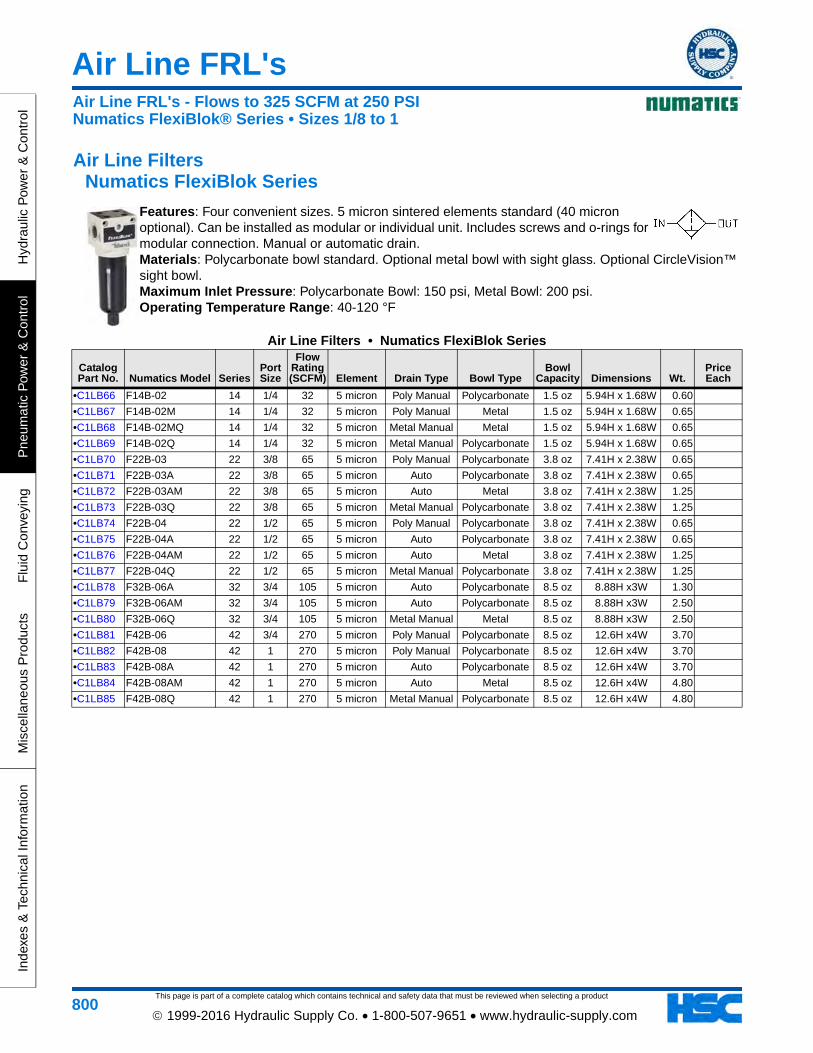
Air Line Filters Numatics FlexiBlok Series
Features: Four convenient sizes. 5 micron sintered elements standard (40 micron optional). Can be installed as modular or individual unit. Includes screws and o-rings for modular connection. Manual or automatic drain. Materials: Polycarbonate bowl standard. Optional metal bowl with sight glass. Optional CircleVision™ sight bowl. Maximum Inlet Pressure: Polycarbonate Bowl: 150 psi, Metal Bowl: 200 psi. Operating Temperature Range: 40-120 °F
Air Line Filters • Numatics FlexiBlok Series
Catalog Part No. Numatics Model Series
Port Size
Flow Rating (SCFM) Element Drain Type Bowl Type
Bowl Capacity Dimensions Wt.
Price Each
•C1LB66 F14B-02 14 1/4 32 5 micron Poly Manual Polycarbonate 1.5 oz 5.94H x 1.68W 0.60
•C1LB67 F14B-02M 14 1/4 32 5 micron Poly Manual Metal 1.5 oz 5.94H x 1.68W 0.65
•C1LB68 F14B-02MQ 14 1/4 32 5 micron Metal Manual Metal 1.5 oz 5.94H x 1.68W 0.65
•C1LB69 F14B-02Q 14 1/4 32 5 micron Metal Manual Polycarbonate 1.5 oz 5.94H x 1.68W 0.65
•C1LB70 F22B-03 22 3/8 65 5 micron Poly Manual Polycarbonate 3.8 oz 7.41H x 2.38W 0.65
•C1LB71 F22B-03A 22 3/8 65 5 micron Auto Polycarbonate 3.8 oz 7.41H x 2.38W 0.65
•C1LB72 F22B-03AM 22 3/8 65 5 micron Auto Metal 3.8 oz 7.41H x 2.38W 1.25
•C1LB73 F22B-03Q 22 3/8 65 5 micron Metal Manual Polycarbonate 3.8 oz 7.41H x 2.38W 1.25
•C1LB74 F22B-04 22 1/2 65 5 micron Poly Manual Polycarbonate 3.8 oz 7.41H x 2.38W 0.65
•C1LB75 F22B-04A 22 1/2 65 5 micron Auto Polycarbonate 3.8 oz 7.41H x 2.38W 0.65
•C1LB76 F22B-04AM 22 1/2 65 5 micron Auto Metal 3.8 oz 7.41H x 2.38W 1.25
•C1LB77 F22B-04Q 22 1/2 65 5 micron Metal Manual Polycarbonate 3.8 oz 7.41H x 2.38W 1.25
•C1LB78 F32B-06A 32 3/4 105 5 micron Auto Polycarbonate 8.5 oz 8.88H x3W 1.30
•C1LB79 F32B-06AM 32 3/4 105 5 micron Auto Polycarbonate 8.5 oz 8.88H x3W 2.50
•C1LB80 F32B-06Q 32 3/4 105 5 micron Metal Manual Metal 8.5 oz 8.88H x3W 2.50
•C1LB81 F42B-06 42 3/4 270 5 micron Poly Manual Polycarbonate 8.5 oz 12.6H x4W 3.70
•C1LB82 F42B-08 42 1 270 5 micron Poly Manual Polycarbonate 8.5 oz 12.6H x4W 3.70
•C1LB83 F42B-08A 42 1 270 5 micron Auto Polycarbonate 8.5 oz 12.6H x4W 3.70
•C1LB84 F42B-08AM 42 1 270 5 micron Auto Metal 8.5 oz 12.6H x4W 4.80
•C1LB85 F42B-08Q 42 1 270 5 micron Metal Manual Polycarbonate 8.5 oz 12.6H x4W 4.80
Air Line FRL's - Flows to 325 SCFM at 250 PSINumatics FlexiBlok® Series • Sizes 1/8 to 1
Air Line FRL's
This page is part of a complete catalog which contains technical and safety data that must be reviewed when selecting a product
Hydraulic P
ower &
Control
Pneum
atic Pow
er & C
ontrolF
luid Conveying
Miscellaneous P
roductsIndexes &
Technical Information
801 1999-2016 Hydraulic Supply Co. • 1-800-507-9651 • www.hydraulic-supply.com
Air Line Regulators Numatics FlexiBlok Series
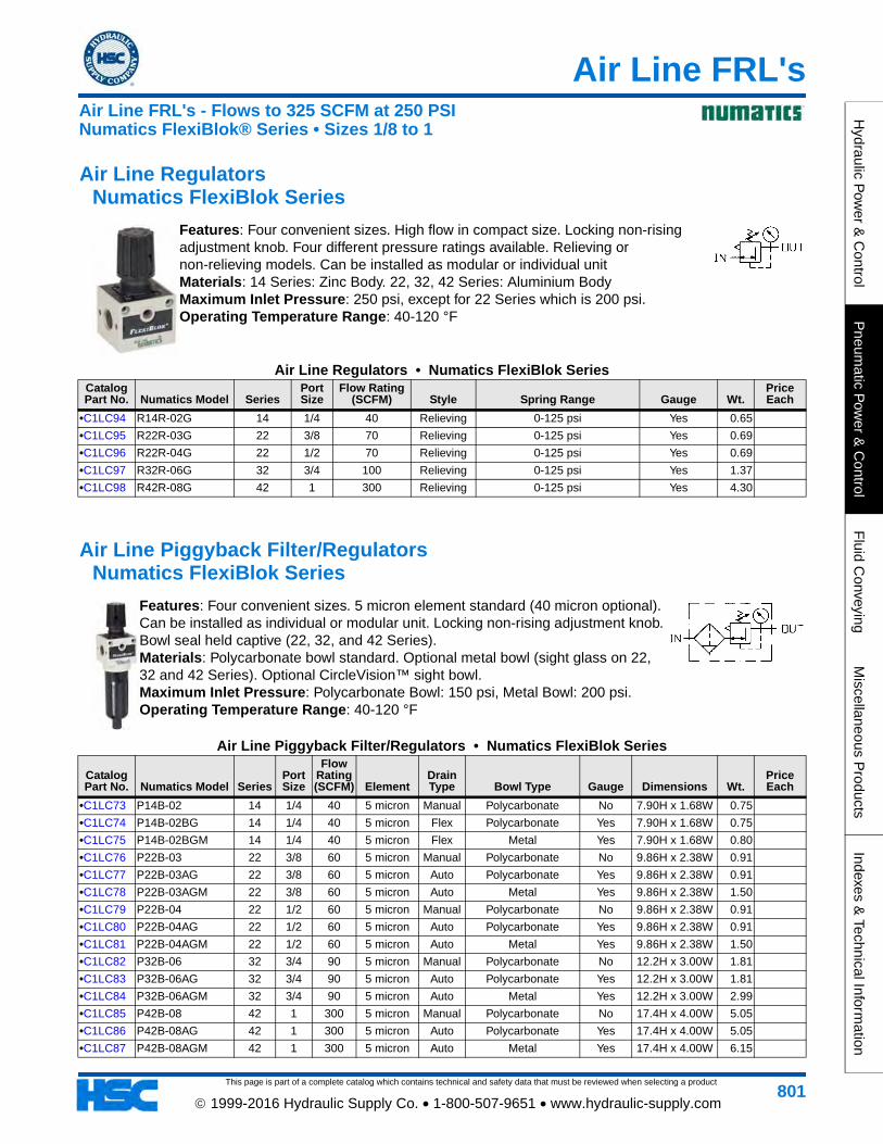
Features: Four convenient sizes. High flow in compact size. Locking non-rising adjustment knob. Four different pressure ratings available. Relieving or non-relieving models. Can be installed as modular or individual unit Materials: 14 Series: Zinc Body. 22, 32, 42 Series: Aluminium Body Maximum Inlet Pressure: 250 psi, except for 22 Series which is 200 psi. Operating Temperature Range: 40-120 °F
Air Line Regulators • Numatics FlexiBlok SeriesCatalog Part No. Numatics Model Series
Port Size
Flow Rating (SCFM) Style Spring Range Gauge Wt.
Price Each
•C1LC94 R14R-02G 14 1/4 40 Relieving 0-125 psi Yes 0.65
•C1LC95 R22R-03G 22 3/8 70 Relieving 0-125 psi Yes 0.69
•C1LC96 R22R-04G 22 1/2 70 Relieving 0-125 psi Yes 0.69
•C1LC97 R32R-06G 32 3/4 100 Relieving 0-125 psi Yes 1.37
•C1LC98 R42R-08G 42 1 300 Relieving 0-125 psi Yes 4.30
Air Line Piggyback Filter/Regulators Numatics FlexiBlok Series
Features: Four convenient sizes. 5 micron element standard (40 micron optional). Can be installed as individual or modular unit. Locking non-rising adjustment knob. Bowl seal held captive (22, 32, and 42 Series). Materials: Polycarbonate bowl standard. Optional metal bowl (sight glass on 22, 32 and 42 Series). Optional CircleVision™ sight bowl. Maximum Inlet Pressure: Polycarbonate Bowl: 150 psi, Metal Bowl: 200 psi. Operating Temperature Range: 40-120 °F
Air Line Piggyback Filter/Regulators • Numatics FlexiBlok Series
Catalog Part No. Numatics Model Series
Port Size
Flow Rating (SCFM) Element
Drain Type Bowl Type Gauge Dimensions Wt.
Price Each
•C1LC73 P14B-02 14 1/4 40 5 micron Manual Polycarbonate No 7.90H x 1.68W 0.75
•C1LC74 P14B-02BG 14 1/4 40 5 micron Flex Polycarbonate Yes 7.90H x 1.68W 0.75
•C1LC75 P14B-02BGM 14 1/4 40 5 micron Flex Metal Yes 7.90H x 1.68W 0.80
•C1LC76 P22B-03 22 3/8 60 5 micron Manual Polycarbonate No 9.86H x 2.38W 0.91
•C1LC77 P22B-03AG 22 3/8 60 5 micron Auto Polycarbonate Yes 9.86H x 2.38W 0.91
•C1LC78 P22B-03AGM 22 3/8 60 5 micron Auto Metal Yes 9.86H x 2.38W 1.50
•C1LC79 P22B-04 22 1/2 60 5 micron Manual Polycarbonate No 9.86H x 2.38W 0.91
•C1LC80 P22B-04AG 22 1/2 60 5 micron Auto Polycarbonate Yes 9.86H x 2.38W 0.91
•C1LC81 P22B-04AGM 22 1/2 60 5 micron Auto Metal Yes 9.86H x 2.38W 1.50
•C1LC82 P32B-06 32 3/4 90 5 micron Manual Polycarbonate No 12.2H x 3.00W 1.81
•C1LC83 P32B-06AG 32 3/4 90 5 micron Auto Polycarbonate Yes 12.2H x 3.00W 1.81
•C1LC84 P32B-06AGM 32 3/4 90 5 micron Auto Metal Yes 12.2H x 3.00W 2.99
•C1LC85 P42B-08 42 1 300 5 micron Manual Polycarbonate No 17.4H x 4.00W 5.05
•C1LC86 P42B-08AG 42 1 300 5 micron Auto Polycarbonate Yes 17.4H x 4.00W 5.05
•C1LC87 P42B-08AGM 42 1 300 5 micron Auto Metal Yes 17.4H x 4.00W 6.15
Air Line FRL's - Flows to 325 SCFM at 250 PSINumatics FlexiBlok® Series • Sizes 1/8 to 1
This page is part of a complete catalog which contains technical and safety data that must be reviewed when selecting a product
Air Line FRL's
Hyd
raul
ic P
ower
& C
ontr
olP
neum
atic
Pow
er &
Con
trol
Flu
id C
onve
ying
Mis
cella
neou
s P
rodu
cts
Inde
xes
& T
echn
ical
Info
rmat
ion
802 1999-2016 Hydraulic Supply Co. • 1-800-507-9651 • www.hydraulic-supply.com
Air Line Lubricators Numatics FlexiBlok Series
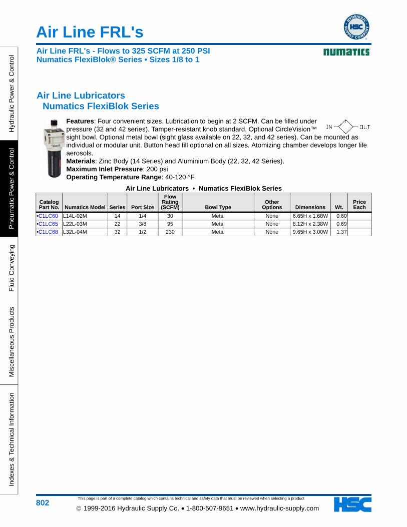
Features: Four convenient sizes. Lubrication to begin at 2 SCFM. Can be filled under pressure (32 and 42 series). Tamper-resistant knob standard. Optional CircleVision™ sight bowl. Optional metal bowl (sight glass available on 22, 32, and 42 series). Can be mounted as individual or modular unit. Button head fill optional on all sizes. Atomizing chamber develops longer life aerosols. Materials: Zinc Body (14 Series) and Aluminium Body (22, 32, 42 Series). Maximum Inlet Pressure: 200 psi Operating Temperature Range: 40-120 °F
Air Line Lubricators • Numatics FlexiBlok Series
Catalog Part No. Numatics Model Series Port Size
Flow Rating (SCFM) Bowl Type
Other Options Dimensions Wt.
Price Each
•C1LC60 L14L-02M 14 1/4 30 Metal None 6.65H x 1.68W 0.60
•C1LC65 L22L-03M 22 3/8 95 Metal None 8.12H x 2.38W 0.69
•C1LC68 L32L-04M 32 1/2 230 Metal None 9.65H x 3.00W 1.37
Air Line FRL's - Flows to 325 SCFM at 250 PSINumatics FlexiBlok® Series • Sizes 1/8 to 1
Air Line Filters
This page is part of a complete catalog which contains technical and safety data that must be reviewed when selecting a product
Hydraulic P
ower &
Control
Pneum
atic Pow
er & C
ontrolF
luid Conveying
Miscellaneous P
roductsIndexes &
Technical Information
803 1999-2016 Hydraulic Supply Co. • 1-800-507-9651 • www.hydraulic-supply.com
Air Line Filters Numatics Delta 901X Series
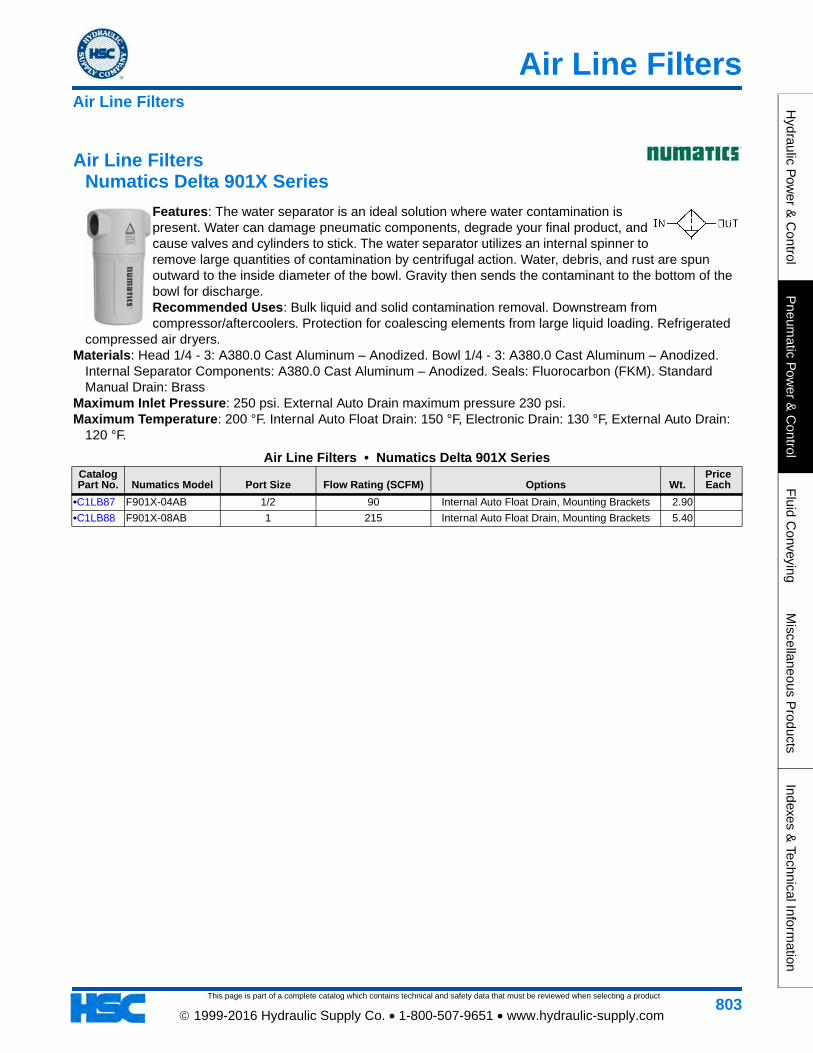
Features: The water separator is an ideal solution where water contamination is present. Water can damage pneumatic components, degrade your final product, and cause valves and cylinders to stick. The water separator utilizes an internal spinner to remove large quantities of contamination by centrifugal action. Water, debris, and rust are spun outward to the inside diameter of the bowl. Gravity then sends the contaminant to the bottom of the bowl for discharge. Recommended Uses: Bulk liquid and solid contamination removal. Downstream from compressor/aftercoolers. Protection for coalescing elements from large liquid loading. Refrigerated
compressed air dryers. Materials: Head 1/4 - 3: A380.0 Cast Aluminum – Anodized. Bowl 1/4 - 3: A380.0 Cast Aluminum – Anodized.
Internal Separator Components: A380.0 Cast Aluminum – Anodized. Seals: Fluorocarbon (FKM). Standard Manual Drain: Brass
Maximum Inlet Pressure: 250 psi. External Auto Drain maximum pressure 230 psi. Maximum Temperature: 200 °F. Internal Auto Float Drain: 150 °F, Electronic Drain: 130 °F, External Auto Drain:
120 °F.
Air Line Filters • Numatics Delta 901X SeriesCatalog Part No. Numatics Model Port Size Flow Rating (SCFM) Options Wt.
Price Each
•C1LB87 F901X-04AB 1/2 90 Internal Auto Float Drain, Mounting Brackets 2.90
•C1LB88 F901X-08AB 1 215 Internal Auto Float Drain, Mounting Brackets 5.40
Air Line Filters
This page is part of a complete catalog which contains technical and safety data that must be reviewed when selecting a product
Pneumatic System Accessories
Hyd
raul
ic P
ower
& C
ontr
olP
neum
atic
Pow
er &
Con
trol
Flu
id C
onve
ying
Mis
cella
neou
s P
rodu
cts
Inde
xes
& T
echn
ical
Info
rmat
ion
804 1999-2016 Hydraulic Supply Co. • 1-800-507-9651 • www.hydraulic-supply.com
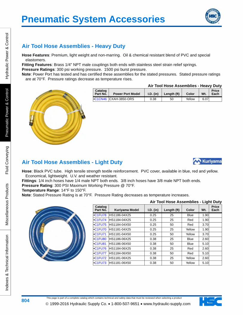
Air Tool Hose Assemblies - Heavy Duty
Hose Features: Premium, light weight and non-marring. Oil & chemical resistant blend of PVC and special elastomers.
Fitting Features: Brass 1/4" NPT male couplings both ends with stainless steel strain relief springs. Pressure Ratings: 300 psi working pressure. 1500 psi burst pressure. Note: Power Port has tested and has certified these assemblies for the stated pressures. Stated pressure ratings
are at 70°F. Pressure ratings decrease as temperature rises.
Air Tool Hose Assemblies - Heavy DutyCatalog Part No. Power Port Model I.D. (in) Length (ft) Color Wt.
Price Each
•C1CN46 CXAH-3850-ORS 0.38 50 Yellow 6.07
Air Tool Hose Assemblies - Light Duty
Hose: Black PVC tube. High tensile strength textile reinforcement. PVC cover, available in blue, red and yellow. Economical, lightweight. U.V. and weather resistant.
Fittings: 1/4 inch hoses have 1/4 male NPT both ends. 3/8 inch hoses have 3/8 male NPT both ends. Pressure Rating: 300 PSI Maximum Working Pressure @ 70°F. Temperature Range: 14°F to 150°F. Note: Stated Pressure Rating is at 70°F. Pressure Rating decreases as temperature increases.
Air Tool Hose Assemblies - Light DutyCatalog Part No. Kuriyama Model I.D. (in) Length (ft) Color Wt.
Price Each
•C1FU78 HS1186-04X25 0.25 25 Blue 1.90
•C1FU74 HS1184-04X25 0.25 25 Red 1.90
•C1FU75 HS1184-04X50 0.25 50 Red 3.70
•C1FU70 HS1181-04X25 0.25 25 Yellow 1.90
•C1FU71 HS1181-04X50 0.25 50 Yellow 3.70
•C1FU80 HS1186-06X25 0.38 25 Blue 2.60
•C1FU81 HS1186-06X50 0.38 50 Blue 5.10
•C1FU76 HS1184-06X25 0.38 25 Red 2.60
•C1FU77 HS1184-06X50 0.38 50 Red 5.10
•C1FU72 HS1181-06X25 0.38 25 Yellow 2.60
•C1FU73 HS1181-06X50 0.38 50 Yellow 5.10
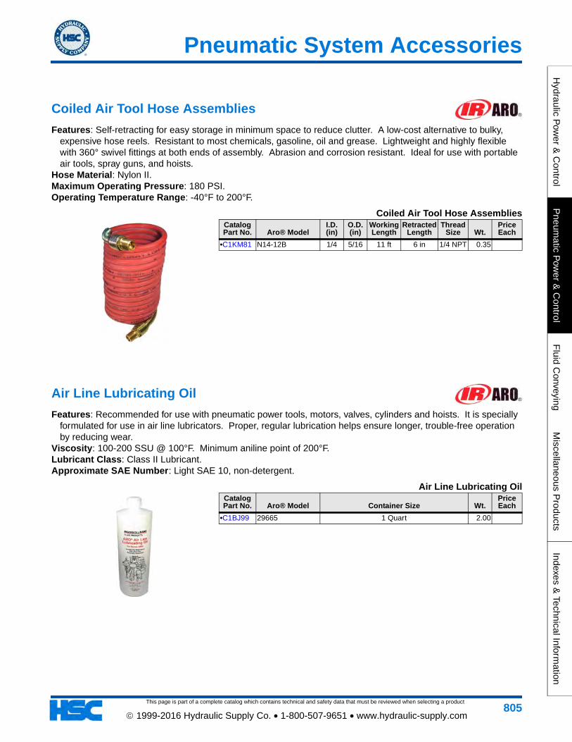
This page is part of a complete catalog which contains technical and safety data that must be reviewed when selecting a product
Pneumatic System Accessories
Hydraulic P
ower &
Control
Pneum
atic Pow
er & C
ontrolF
luid Conveying
Miscellaneous P
roductsIndexes &
Technical Information
805 1999-2016 Hydraulic Supply Co. • 1-800-507-9651 • www.hydraulic-supply.com
Coiled Air Tool Hose Assemblies
Features: Self-retracting for easy storage in minimum space to reduce clutter. A low-cost alternative to bulky, expensive hose reels. Resistant to most chemicals, gasoline, oil and grease. Lightweight and highly flexible with 360° swivel fittings at both ends of assembly. Abrasion and corrosion resistant. Ideal for use with portable air tools, spray guns, and hoists.
Hose Material: Nylon II. Maximum Operating Pressure: 180 PSI. Operating Temperature Range: -40°F to 200°F.
Coiled Air Tool Hose AssembliesCatalog Part No. Aro® Model
I.D. (in)
O.D. (in)
Working Length
Retracted Length
Thread Size Wt.
Price Each
•C1KM81 N14-12B 1/4 5/16 11 ft 6 in 1/4 NPT 0.35
Air Line Lubricating Oil
Features: Recommended for use with pneumatic power tools, motors, valves, cylinders and hoists. It is specially formulated for use in air line lubricators. Proper, regular lubrication helps ensure longer, trouble-free operation by reducing wear.
Viscosity: 100-200 SSU @ 100°F. Minimum aniline point of 200°F. Lubricant Class: Class II Lubricant. Approximate SAE Number: Light SAE 10, non-detergent.
Air Line Lubricating OilCatalog Part No. Aro® Model Container Size Wt.
Price Each
•C1BJ99 29665 1 Quart 2.00
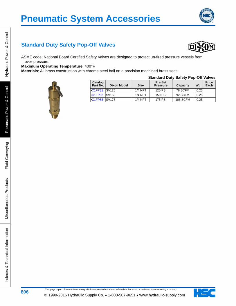
This page is part of a complete catalog which contains technical and safety data that must be reviewed when selecting a product
Pneumatic System Accessories
Hyd
raul
ic P
ower
& C
ontr
olP
neum
atic
Pow
er &
Con
trol
Flu
id C
onve
ying
Mis
cella
neou
s P
rodu
cts
Inde
xes
& T
echn
ical
Info
rmat
ion
806 1999-2016 Hydraulic Supply Co. • 1-800-507-9651 • www.hydraulic-supply.com
Standard Duty Safety Pop-Off Valves
ASME code, National Board Certified Safety Valves are designed to protect un-fired pressure vessels from over-pressure.
Maximum Operating Temperature: 400°F. Materials: All brass construction with chrome steel ball on a precision machined brass seat.
Standard Duty Safety Pop-Off ValvesCatalog Part No. Dixon Model Size
Pre-Set Pressure Capacity Wt.
Price Each
•C1FP81 SV125 1/4 NPT 125 PSI 78 SCFM 0.25
•C1FP82 SV150 1/4 NPT 150 PSI 92 SCFM 0.25
•C1FP83 SV175 1/4 NPT 175 PSI 106 SCFM 0.25
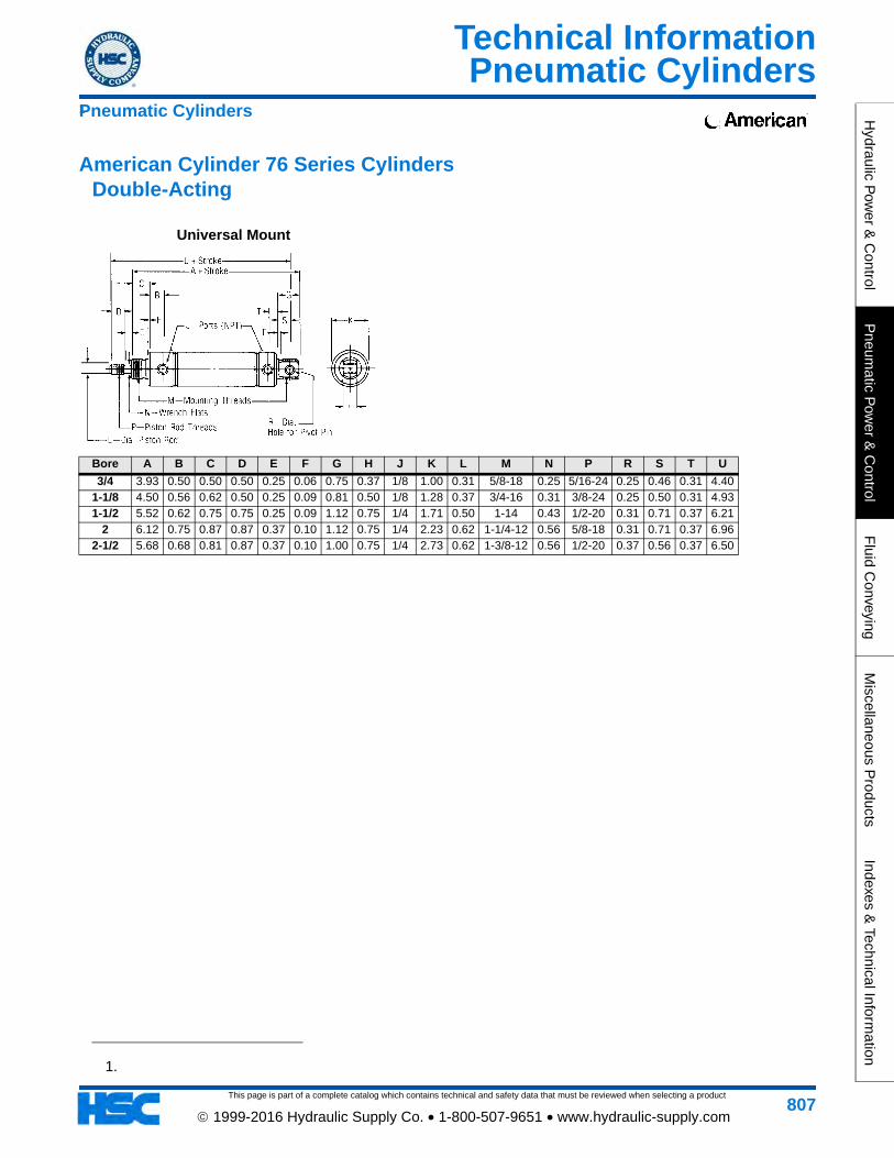
Pneumatic Cylinders
This page is part of a complete catalog which contains technical and safety data that must be reviewed when selecting a product
Technical InformationH
ydraulic Pow
er & C
ontrolP
neumatic P
ower &
Control
Fluid C
onveyingM
iscellaneous Products
Indexes & Technical Inform
ation
807 1999-2016 Hydraulic Supply Co. • 1-800-507-9651 • www.hydraulic-supply.com
1
1.
Pneumatic Cylinders
Universal Mount
American Cylinder 76 Series Cylinders Double-Acting
Bore A B C D E F G H J K L M N P R S T U
3/4 3.93 0.50 0.50 0.50 0.25 0.06 0.75 0.37 1/8 1.00 0.31 5/8-18 0.25 5/16-24 0.25 0.46 0.31 4.401-1/8 4.50 0.56 0.62 0.50 0.25 0.09 0.81 0.50 1/8 1.28 0.37 3/4-16 0.31 3/8-24 0.25 0.50 0.31 4.931-1/2 5.52 0.62 0.75 0.75 0.25 0.09 1.12 0.75 1/4 1.71 0.50 1-14 0.43 1/2-20 0.31 0.71 0.37 6.21
2 6.12 0.75 0.87 0.87 0.37 0.10 1.12 0.75 1/4 2.23 0.62 1-1/4-12 0.56 5/8-18 0.31 0.71 0.37 6.962-1/2 5.68 0.68 0.81 0.87 0.37 0.10 1.00 0.75 1/4 2.73 0.62 1-3/8-12 0.56 1/2-20 0.37 0.56 0.37 6.50
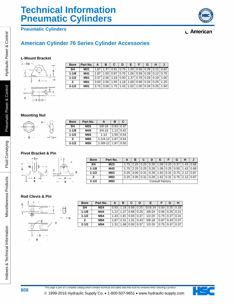
This page is part of a complete catalog which contains technical and safety data that must be reviewed when selecting a product
Pneumatic CylindersTechnical Information
Hyd
raul
ic P
ower
& C
ontr
olP
neum
atic
Pow
er &
Con
trol
Flu
id C
onve
ying
Mis
cella
neou
s P
rodu
cts
Inde
xes
& T
echn
ical
Info
rmat
ion
808 1999-2016 Hydraulic Supply Co. • 1-800-507-9651 • www.hydraulic-supply.com
American Cylinder 76 Series Cylinder Accessories
L-Mount Bracket
Pneumatic Cylinders
Mounting Nut
Pivot Bracket & Pin
Rod Clevis & Pin
Bore Part No. A B C D E F G H J
3/4 M23 1.75 2.25 0.25 0.28 1.09 0.25 0.37 1.43 0.681-1/8 M43 1.75 2.25 0.25 0.28 1.09 0.25 0.50 1.43 0.681-1/2 M63 2.25 3.00 0.31 0.28 1.62 0.31 0.75 2.12 0.87
2 M83 2.25 3.00 0.31 0.28 1.62 0.31 0.75 2.12 0.872-1/2 M93 Consult Factory
Bore Part No. A B C D E F G H
3/4 M24 0.93 1.18 0.68 0.25 5/16-24 0.50 0.25 0.181-1/8 M44 1.12 1.37 0.68 0.25 3/8-24 0.56 0.25 0.211-1/2 M64 1.43 1.81 0.93 0.37 1/2-20 0.75 0.37 0.31
2 M84 1.87 2.31 1.31 0.43 5/8-18 0.87 0.43 0.372-1/2 M94 1.31 1.68 0.93 0.37 1/2-20 0.75 0.37 0.37
Bore Part No. A B C
3/4 M25 5/8-18 0.93 0.371-1/8 M45 3/4-16 1.12 0.421-1/2 M65 1-14 1.50 0.54
2 M85 1-1/4-12 1.87 0.542-1/2 M95 1-3/8-12 1.87 0.50
Bore Part No. A B C D E F G H J
3/4 M21 1.87 1.37 0.81 0.75 1.00 0.56 0.28 0.12 0.621-1/8 M41 1.87 1.50 0.87 0.75 1.06 0.59 0.28 0.12 0.751-1/2 M61 2.37 2.06 1.18 0.93 1.37 0.78 0.28 0.19 1.00
2 M81 3.00 2.56 1.50 1.18 1.68 0.96 0.34 0.25 1.252-1/2 M91 3.75 3.06 1.75 1.43 1.62 1.00 0.34 0.25 1.50
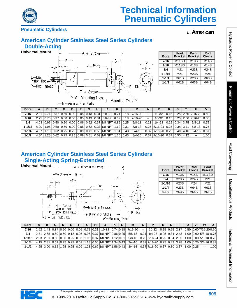
Pneumatic Cylinders
This page is part of a complete catalog which contains technical and safety data that must be reviewed when selecting a product
Technical InformationH
ydraulic Pow
er & C
ontrolP
neumatic P
ower &
Control
Fluid C
onveyingM
iscellaneous Products
Indexes & Technical Inform
ation
809 1999-2016 Hydraulic Supply Co. • 1-800-507-9651 • www.hydraulic-supply.com
Pneumatic Cylinders
American Cylinder Stainless Steel Series Cylinders Double-Acting
American Cylinder Stainless Steel Series Cylinders Single-Acting Spring-Extended
Universal Mount
Universal Mount
Bore A B C D E F G H J K L M N P R S T U V
7/16 2.81 0.71 0.37 0.50 0.00 0.05 0.43 0.31 10-32 0.74 0.18 7/16-20 -- 10-32 0.15 0.25 2.56 7/16-20 0.509/16 2.75 0.75 0.37 0.50 0.00 0.05 0.43 0.31 10-32 0.62 0.18 7/16-20 -- 10-32 0.15 0.25 2.56 7/16-20 0.503/4 4.03 0.96 0.50 0.50 0.00 0.06 0.62 0.37 1/8 NPT 0.86 0.25 5/8-18 0.21 1/4-28 0.25 0.34 3.75 5/8-18 0.75
1-1/16 4.00 1.06 0.50 0.50 0.00 0.06 0.62 0.37 1/8 NPT 1.12 0.31 5/8-18 0.25 5/16-24 0.25 0.34 3.71 5/8-18 0.751-1/4 4.87 1.18 0.62 0.75 0.25 0.09 0.71 0.50 1/8 NPT 1.34 0.43 3/4-16 0.37 7/16-20 0.25 0.40 4.46 3/4-16 0.871-1/2 4.50 1.25 0.62 0.75 0.25 0.09 0.81 0.62 1/8 NPT 1.56 0.43 3/4-16 0.37 7/16-20 0.37 0.50 4.12 -- 1.00
BoreFoot
BracketPivot
BracketRod
Clevis
7/16 M11SD M13S M14S9/16 M11SD M13S M14S3/4 M21 M23S M24S
1-1/16 M21 M23S M241-1/4 M61S M23S M63S1-1/2 M61S M63S M64S
BorePivot
BracketRod
ClevisFoot
Bracket
7/16 M13S M14S M11SD3/4 M23S M24S M21
1-1/16 M23S M24 M211-1/4 M23S M64S M61S1-1/2 M63S M64S M61S
Bore A B C D E F G H J K L M N P R S T U V W X
7/16 2.62 1.43 0.37 0.50 0.00 0.05 0.71 0.31 10-32 0.74 0.18 7/16-20 -- 10-32 0.15 0.25 2.37 0.50 0.00 7/16-20 0.503/4 2.71 2.68 0.50 0.50 0.12 0.05 0.96 0.37 1/8 NPT 0.86 0.25 5/8-18 0.21 1/4-28 0.25 0.34 2.43 1.00 0.00 5/8-18 0.75
1-1/16 2.93 2.81 0.50 0.50 0.25 0.06 1.06 0.37 1/8 NPT 1.12 0.31 5/8-18 0.25 5/16-24 0.25 0.34 2.65 1.00 0.00 5/8-18 0.751-1/4 4.15 2.81 0.62 0.75 0.25 0.09 1.18 0.50 1/8 NPT 1.34 0.43 3/4-16 0.37 7/16-20 0.25 0.43 3.78 1.00 0.25 3/4-16 0.871-1/2 4.25 3.00 0.62 1.25 0.25 0.09 1.25 0.62 1/8 NPT 1.56 0.43 3/4-16 0.37 7/16-20 0.37 0.50 3.87 1.00 0.25 -- 1.00
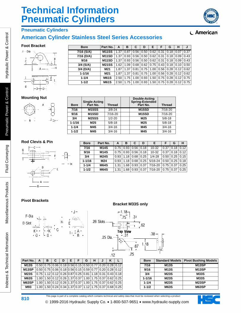
This page is part of a complete catalog which contains technical and safety data that must be reviewed when selecting a product
Pneumatic CylindersTechnical Information
Hyd
raul
ic P
ower
& C
ontr
olP
neum
atic
Pow
er &
Con
trol
Flu
id C
onve
ying
Mis
cella
neou
s P
rodu
cts
Inde
xes
& T
echn
ical
Info
rmat
ion
810 1999-2016 Hydraulic Supply Co. • 1-800-507-9651 • www.hydraulic-supply.com
American Cylinder Stainless Steel Series AccessoriesPneumatic Cylinders
Foot Bracket
Mounting Nut
Rod Clevis & Pin Bore Part No. A B C D E F G H
7/16 M14S 0.75 0.93 0.56 0.18 10-32 0.37 0.18 0.129/16 M14S 0.75 0.93 0.56 0.18 10-32 0.37 0.18 0.123/4 M24S 0.93 1.18 0.68 0.25 1/4-28 0.50 0.25 0.15
1-1/16 M24 0.93 1.18 0.68 0.25 5/16-24 0.50 0.25 0.181-1/4 M64S 1.31 1.68 0.93 0.37 7/16-20 0.75 0.37 0.251-1/2 M64S 1.31 1.68 0.93 0.37 7/16-20 0.75 0.37 0.25
BoreSingle-Acting
Part No. Thread
Double-ActingSpring-Extended
Part No. Thread
7/16 M15SS 3/8-24 M15SD 7/16-209/16 M15SD 7/16-20 M15SD 7/16-203/4 M25SS 1/2-20 M25 5/8-18
1-1/16 M25 5/8-18 M25 5/8-181-1/4 M45 3/4-16 M45 3/4-161-1/2 M45 3/4-16 M45 3/4-16
Bore Part No. A B C D E F G H J
7/16 (S/A) M11SS 1.37 0.87 0.56 0.50 0.62 0.31 0.18 0.07 0.377/16 (D/A) M11SD 1.37 0.93 0.56 0.50 0.62 0.31 0.18 0.09 0.43
9/16 M11SD 1.37 0.93 0.56 0.50 0.62 0.31 0.18 0.09 0.433/4 (S/A) M21SS 1.62 1.09 0.68 0.62 0.75 0.43 0.18 0.10 0.503/4 (D/A) M21 1.87 1.37 0.81 0.75 1.00 0.56 0.28 0.12 0.62
1-1/16 M21 1.87 1.37 0.81 0.75 1.00 0.56 0.28 0.12 0.621-1/4 M61S 2.50 1.75 1.00 0.93 1.50 0.75 0.28 0.12 0.751-1/2 M61S 2.50 1.75 1.00 0.93 1.50 0.75 0.28 0.12 0.75
Pivot BracketsBracket M33S only
Part No. A B C D E F G H J K L
M13S 0.50 0.75 0.06 0.18 0.56 0.15 0.50 0.77 0.20 0.28 0.12M13SP 0.50 0.75 0.06 0.18 0.56 0.15 0.59 0.77 0.20 0.28 0.12M23S 0.75 1.12 0.12 0.26 0.87 0.25 0.81 1.18 0.31 0.43 0.18M63S 1.00 1.50 0.12 0.26 1.37 0.37 1.00 1.75 0.37 0.62 0.25
M63SP 1.00 1.50 0.12 0.26 1.37 0.37 1.00 1.75 0.37 0.62 0.25M93 1.00 1.50 0.24 0.34 1.37 0.37 1.12 1.75 0.37 0.68 0.25
Bore Standard Models Pivot Bushing Models
7/16 M13S M13SP9/16 M13S M13SP3/4 M23S M33S
1-1/16 M23S M33S1-1/4 M23S M23SP1-1/2 M63S M63SP
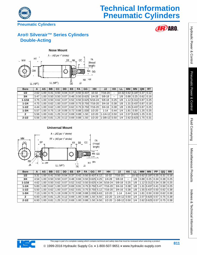
Pneumatic Cylinders
This page is part of a complete catalog which contains technical and safety data that must be reviewed when selecting a product
Technical InformationH
ydraulic Pow
er & C
ontrolP
neumatic P
ower &
Control
Fluid C
onveyingM
iscellaneous Products
Indexes & Technical Inform
ation
811 1999-2016 Hydraulic Supply Co. • 1-800-507-9651 • www.hydraulic-supply.com
Pneumatic Cylinders
Aro® Silverair™ Series Cylinders Double-Acting
Nose Mount
Bore A AS BB CC DD EE FA GG HH JJ KK LL MM MN QM RT
1/2 2.62 1.00 0.41 0.50 0.04 0.37 0.50 0.437 10-32 7/16-20 -- 10-32 0.62 0.187 0.37 0.123/4 3.47 1.00 0.50 0.50 0.07 0.48 0.50 0.625 1/4-28 5/8-18 -- 1/8 0.88 0.25 0.62 0.16
1-1/16 3.75 1.00 0.50 0.62 0.07 0.52 0.50 0.625 5/16-24 5/8-18 0.25 1/8 1.12 0.312 0.87 0.251-1/4 4.75 1.00 0.62 1.00 0.07 0.69 0.75 0.750 7/16-20 3/4-16 0.38 1/8 1.31 0.437 0.87 0.181-1/2 4.44 1.00 0.62 1.00 0.07 0.62 0.75 0.750 7/16-20 3/4-16 0.38 1/8 1.55 0.437 0.87 0.251-3/4 5.57 1.00 0.75 1.19 0.09 0.72 0.88 1.030 1/2-20 1-14 0.44 1/4 1.81 0.50 1.25 0.25
2 5.56 1.00 0.81 1.25 0.12 0.69 0.88 1.50 1/2-20 1-1/4-12 0.50 1/4 2.07 0.625 1.25 0.312-1/2 5.56 1.00 0.81 1.25 0.12 0.69 0.88 1.50 1/2-20 1-3/8-12 0.50 1/4 2.62 0.625 1.75 0.31
Universal Mount
Bore A AS BB CC DD EE EP FA GG FF HH JJ KK LL MM MN PP QQ RR
1/2 3.31 1.00 0.41 0.50 0.04 0.37 0.42 0.50 0.437 6.12 10-32 7/16-20 -- 10-32 0.62 0.187 0.25 0.31 0.163/4 4.54 1.00 0.50 0.50 0.07 0.48 0.66 0.50 0.625 4.25 1/4-28 5/8-18 -- 1/8 0.88 0.25 0.34 0.38 0.25
1-1/16 4.62 1.00 0.50 0.62 0.07 0.52 0.62 0.50 0.625 4.34 5/16-24 5/8-18 0.25 1/8 1.12 0.312 0.34 0.38 0.251-1/4 5.83 1.00 0.62 1.00 0.07 0.69 0.91 0.75 0.750 5.47 7/16-20 3/4-16 0.38 1/8 1.31 0.437 0.41 0.50 0.251-1/2 5.50 1.00 0.62 1.00 0.07 0.62 0.81 0.75 0.750 5.12 7/16-20 3/4-16 0.38 1/8 1.55 0.437 0.50 0.62 0.381-3/4 7.13 1.00 0.75 1.19 0.09 0.72 0.98 0.88 1.030 6.63 1/2-20 1-14 0.44 1/4 1.81 0.50 0.50 0.62 0.38
2 6.93 1.00 0.81 1.25 0.12 0.69 1.00 0.88 1.50 6.50 1/2-20 1-1/4-12 0.50 1/4 2.07 0.625 0.57 0.75 0.382-1/2 6.93 1.00 0.81 1.25 0.12 0.69 1.00 0.88 1.50 6.50 1/2-20 1-3/8-12 0.50 1/4 2.62 0.625 0.57 0.75 0.38
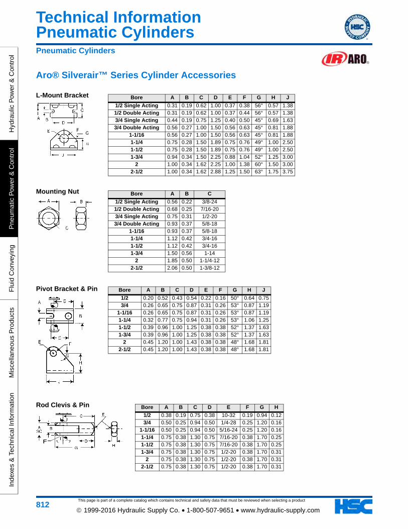
This page is part of a complete catalog which contains technical and safety data that must be reviewed when selecting a product
Pneumatic CylindersTechnical Information
Hyd
raul
ic P
ower
& C
ontr
olP
neum
atic
Pow
er &
Con
trol
Flu
id C
onve
ying
Mis
cella
neou
s P
rodu
cts
Inde
xes
& T
echn
ical
Info
rmat
ion
812 1999-2016 Hydraulic Supply Co. • 1-800-507-9651 • www.hydraulic-supply.com
L-Mount Bracket
Aro® Silverair™ Series Cylinder Accessories
Pneumatic Cylinders
Mounting Nut
Pivot Bracket & Pin
Rod Clevis & Pin
Bore A B C D E F G H J
1/2 Single Acting 0.31 0.19 0.62 1.00 0.37 0.38 56° 0.57 1.381/2 Double Acting 0.31 0.19 0.62 1.00 0.37 0.44 56° 0.57 1.383/4 Single Acting 0.44 0.19 0.75 1.25 0.40 0.50 45° 0.69 1.633/4 Double Acting 0.56 0.27 1.00 1.50 0.56 0.63 45° 0.81 1.88
1-1/16 0.56 0.27 1.00 1.50 0.56 0.63 45° 0.81 1.881-1/4 0.75 0.28 1.50 1.89 0.75 0.76 49° 1.00 2.501-1/2 0.75 0.28 1.50 1.89 0.75 0.76 49° 1.00 2.501-3/4 0.94 0.34 1.50 2.25 0.88 1.04 52° 1.25 3.00
2 1.00 0.34 1.62 2.25 1.00 1.38 60° 1.50 3.002-1/2 1.00 0.34 1.62 2.88 1.25 1.50 63° 1.75 3.75
Bore A B C
1/2 Single Acting 0.56 0.22 3/8-241/2 Double Acting 0.68 0.25 7/16-203/4 Single Acting 0.75 0.31 1/2-203/4 Double Acting 0.93 0.37 5/8-18
1-1/16 0.93 0.37 5/8-181-1/4 1.12 0.42 3/4-161-1/2 1.12 0.42 3/4-161-3/4 1.50 0.56 1-14
2 1.85 0.50 1-1/4-122-1/2 2.06 0.50 1-3/8-12
Bore A B C D E F G H J
1/2 0.20 0.52 0.43 0.54 0.22 0.16 50° 0.64 0.753/4 0.26 0.65 0.75 0.87 0.31 0.26 53° 0.87 1.19
1-1/16 0.26 0.65 0.75 0.87 0.31 0.26 53° 0.87 1.191-1/4 0.32 0.77 0.75 0.94 0.31 0.26 53° 1.06 1.251-1/2 0.39 0.96 1.00 1.25 0.38 0.38 52° 1.37 1.631-3/4 0.39 0.96 1.00 1.25 0.38 0.38 52° 1.37 1.63
2 0.45 1.20 1.00 1.43 0.38 0.38 48° 1.68 1.812-1/2 0.45 1.20 1.00 1.43 0.38 0.38 48° 1.68 1.81
Bore A B C D E F G H
1/2 0.38 0.19 0.75 0.38 10-32 0.19 0.94 0.123/4 0.50 0.25 0.94 0.50 1/4-28 0.25 1.20 0.16
1-1/16 0.50 0.25 0.94 0.50 5/16-24 0.25 1.20 0.161-1/4 0.75 0.38 1.30 0.75 7/16-20 0.38 1.70 0.251-1/2 0.75 0.38 1.30 0.75 7/16-20 0.38 1.70 0.251-3/4 0.75 0.38 1.30 0.75 1/2-20 0.38 1.70 0.31
2 0.75 0.38 1.30 0.75 1/2-20 0.38 1.70 0.312-1/2 0.75 0.38 1.30 0.75 1/2-20 0.38 1.70 0.31
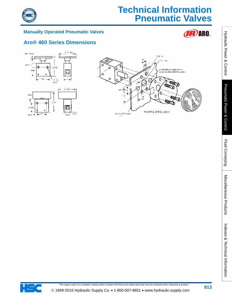
Pneumatic Valves
This page is part of a complete catalog which contains technical and safety data that must be reviewed when selecting a product
Technical InformationH
ydraulic Pow
er & C
ontrolP
neumatic P
ower &
Control
Fluid C
onveyingM
iscellaneous Products
Indexes & Technical Inform
ation
813 1999-2016 Hydraulic Supply Co. • 1-800-507-9651 • www.hydraulic-supply.com
Manually Operated Pneumatic Valves
Aro® 460 Series Dimensions
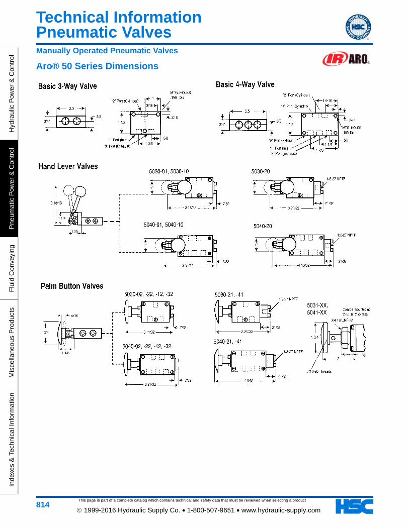
This page is part of a complete catalog which contains technical and safety data that must be reviewed when selecting a product
Pneumatic ValvesTechnical Information
Hyd
raul
ic P
ower
& C
ontr
olP
neum
atic
Pow
er &
Con
trol
Flu
id C
onve
ying
Mis
cella
neou
s P
rodu
cts
Inde
xes
& T
echn
ical
Info
rmat
ion
814 1999-2016 Hydraulic Supply Co. • 1-800-507-9651 • www.hydraulic-supply.com
Manually Operated Pneumatic Valves
Aro® 50 Series Dimensions
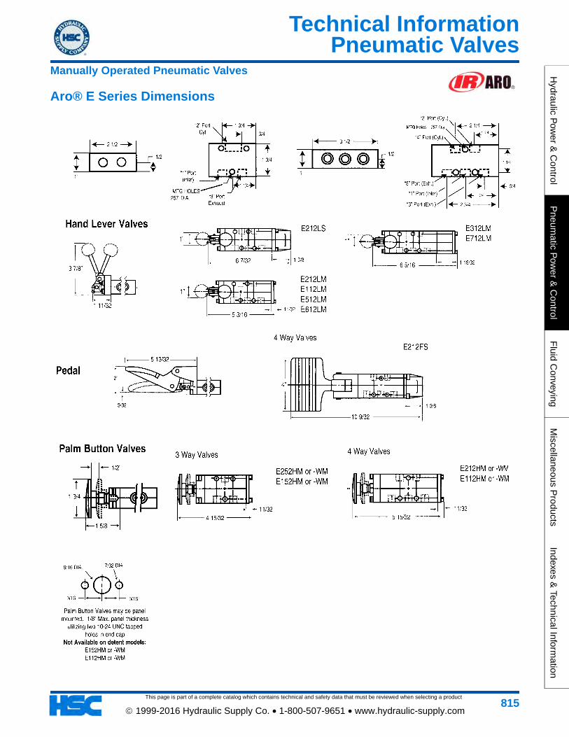
Pneumatic Valves
This page is part of a complete catalog which contains technical and safety data that must be reviewed when selecting a product
Technical InformationH
ydraulic Pow
er & C
ontrolP
neumatic P
ower &
Control
Fluid C
onveyingM
iscellaneous Products
Indexes & Technical Inform
ation
815 1999-2016 Hydraulic Supply Co. • 1-800-507-9651 • www.hydraulic-supply.com
Aro® E Series Dimensions
Manually Operated Pneumatic Valves
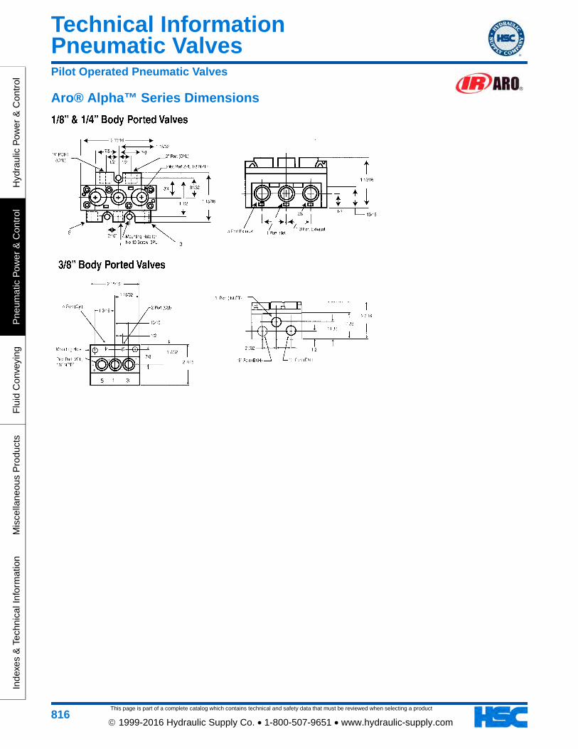
This page is part of a complete catalog which contains technical and safety data that must be reviewed when selecting a product
Pneumatic ValvesTechnical Information
Hyd
raul
ic P
ower
& C
ontr
olP
neum
atic
Pow
er &
Con
trol
Flu
id C
onve
ying
Mis
cella
neou
s P
rodu
cts
Inde
xes
& T
echn
ical
Info
rmat
ion
816 1999-2016 Hydraulic Supply Co. • 1-800-507-9651 • www.hydraulic-supply.com
Pilot Operated Pneumatic Valves
Aro® Alpha™ Series Dimensions
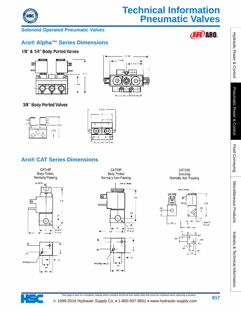
Pneumatic Valves
This page is part of a complete catalog which contains technical and safety data that must be reviewed when selecting a product
Technical InformationH
ydraulic Pow
er & C
ontrolP
neumatic P
ower &
Control
Fluid C
onveyingM
iscellaneous Products
Indexes & Technical Inform
ation
817 1999-2016 Hydraulic Supply Co. • 1-800-507-9651 • www.hydraulic-supply.com
Solenoid Operated Pneumatic Valves
Aro® CAT Series Dimensions
Aro® Alpha™ Series Dimensions
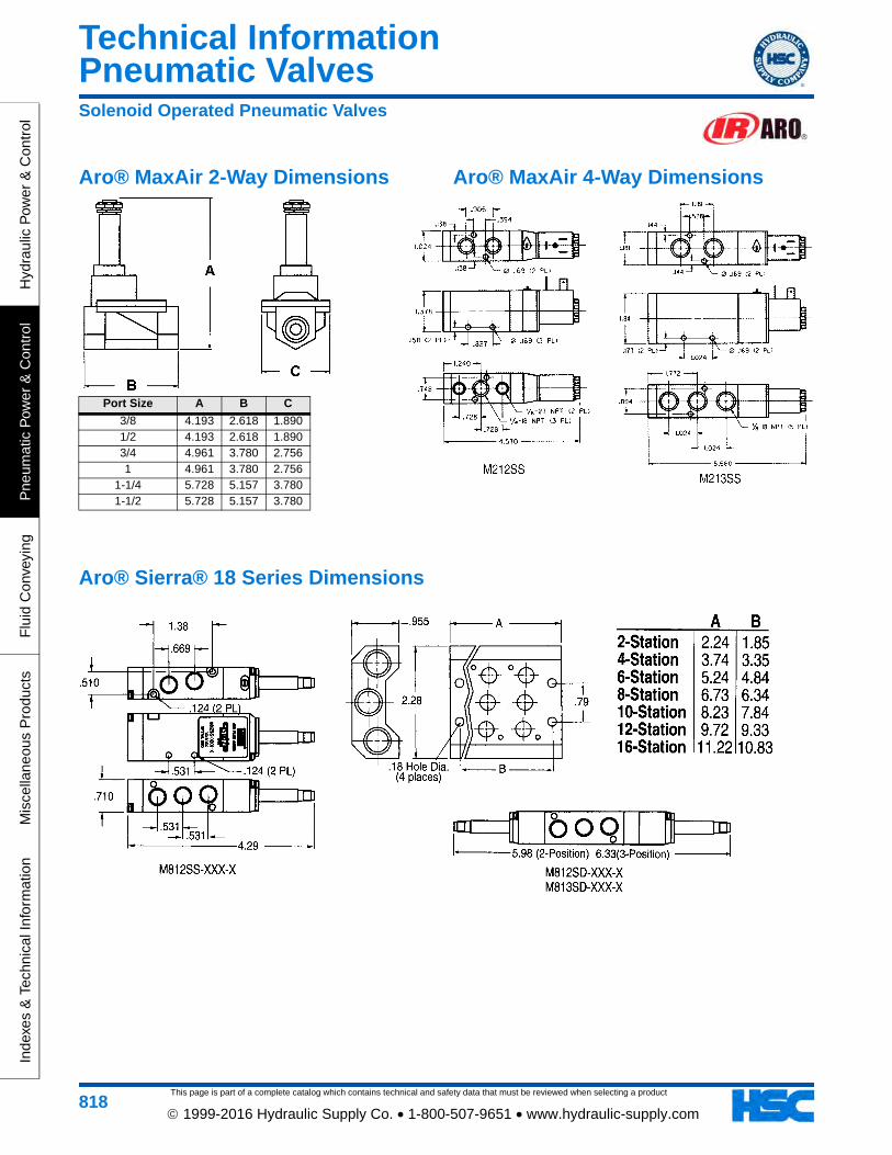
This page is part of a complete catalog which contains technical and safety data that must be reviewed when selecting a product
Pneumatic ValvesTechnical Information
Hyd
raul
ic P
ower
& C
ontr
olP
neum
atic
Pow
er &
Con
trol
Flu
id C
onve
ying
Mis
cella
neou
s P
rodu
cts
Inde
xes
& T
echn
ical
Info
rmat
ion
818 1999-2016 Hydraulic Supply Co. • 1-800-507-9651 • www.hydraulic-supply.com
Solenoid Operated Pneumatic Valves
Aro® MaxAir 4-Way DimensionsAro® MaxAir 2-Way Dimensions
Port Size A B C
3/8 4.193 2.618 1.8901/2 4.193 2.618 1.8903/4 4.961 3.780 2.7561 4.961 3.780 2.756
1-1/4 5.728 5.157 3.7801-1/2 5.728 5.157 3.780
Aro® Sierra® 18 Series Dimensions
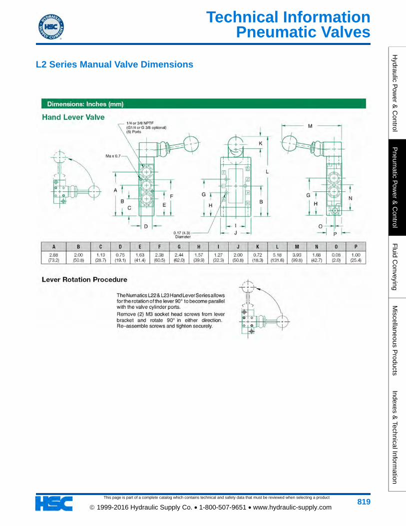
Pneumatic Valves
This page is part of a complete catalog which contains technical and safety data that must be reviewed when selecting a product
Technical InformationH
ydraulic Pow
er & C
ontrolP
neumatic P
ower &
Control
Fluid C
onveyingM
iscellaneous Products
Indexes & Technical Inform
ation
819 1999-2016 Hydraulic Supply Co. • 1-800-507-9651 • www.hydraulic-supply.com
L2 Series Manual Valve Dimensions
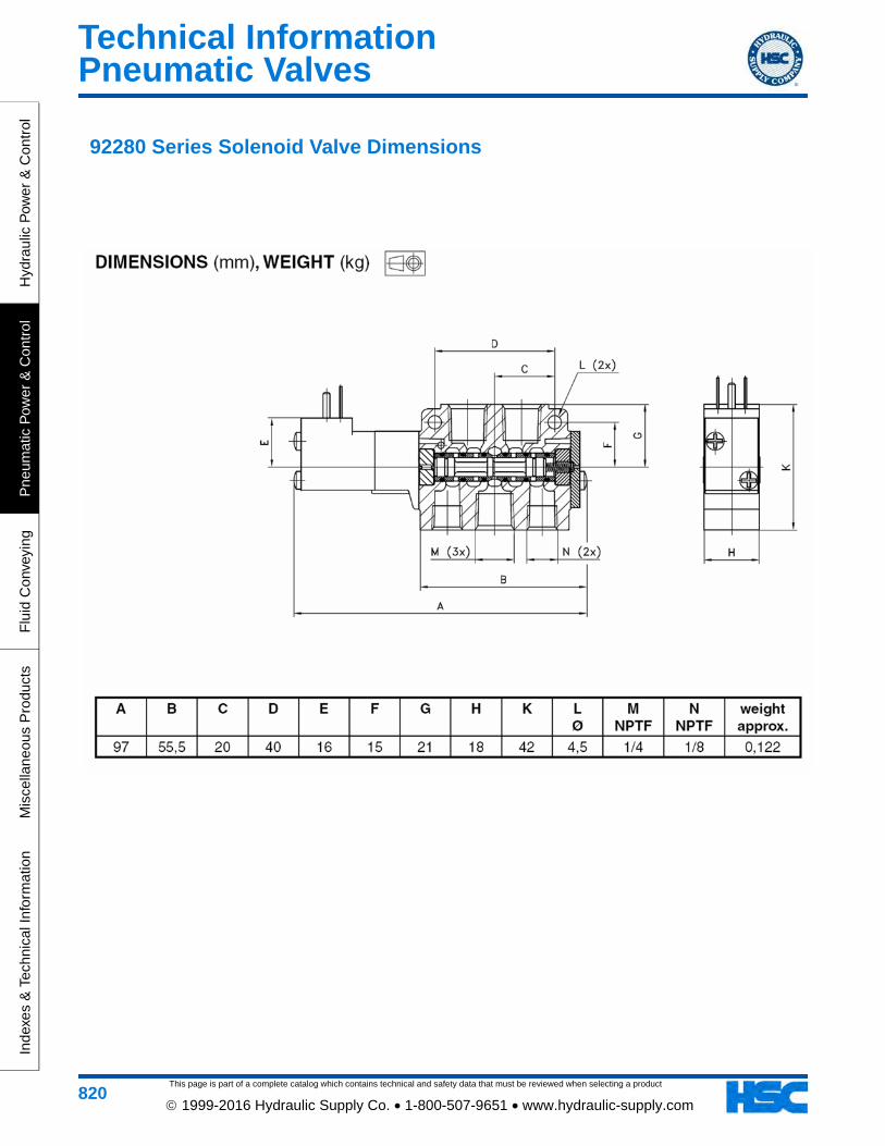
This page is part of a complete catalog which contains technical and safety data that must be reviewed when selecting a product
Pneumatic ValvesTechnical Information
Hyd
raul
ic P
ower
& C
ontr
olP
neum
atic
Pow
er &
Con
trol
Flu
id C
onve
ying
Mis
cella
neou
s P
rodu
cts
Inde
xes
& T
echn
ical
Info
rmat
ion
820 1999-2016 Hydraulic Supply Co. • 1-800-507-9651 • www.hydraulic-supply.com
92280 Series Solenoid Valve Dimensions
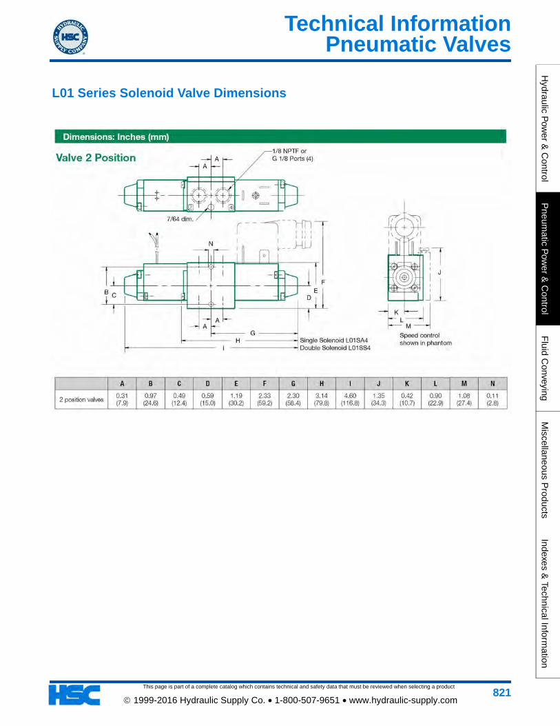
Pneumatic Valves
This page is part of a complete catalog which contains technical and safety data that must be reviewed when selecting a product
Technical InformationH
ydraulic Pow
er & C
ontrolP
neumatic P
ower &
Control
Fluid C
onveyingM
iscellaneous Products
Indexes & Technical Inform
ation
821 1999-2016 Hydraulic Supply Co. • 1-800-507-9651 • www.hydraulic-supply.com
L01 Series Solenoid Valve Dimensions
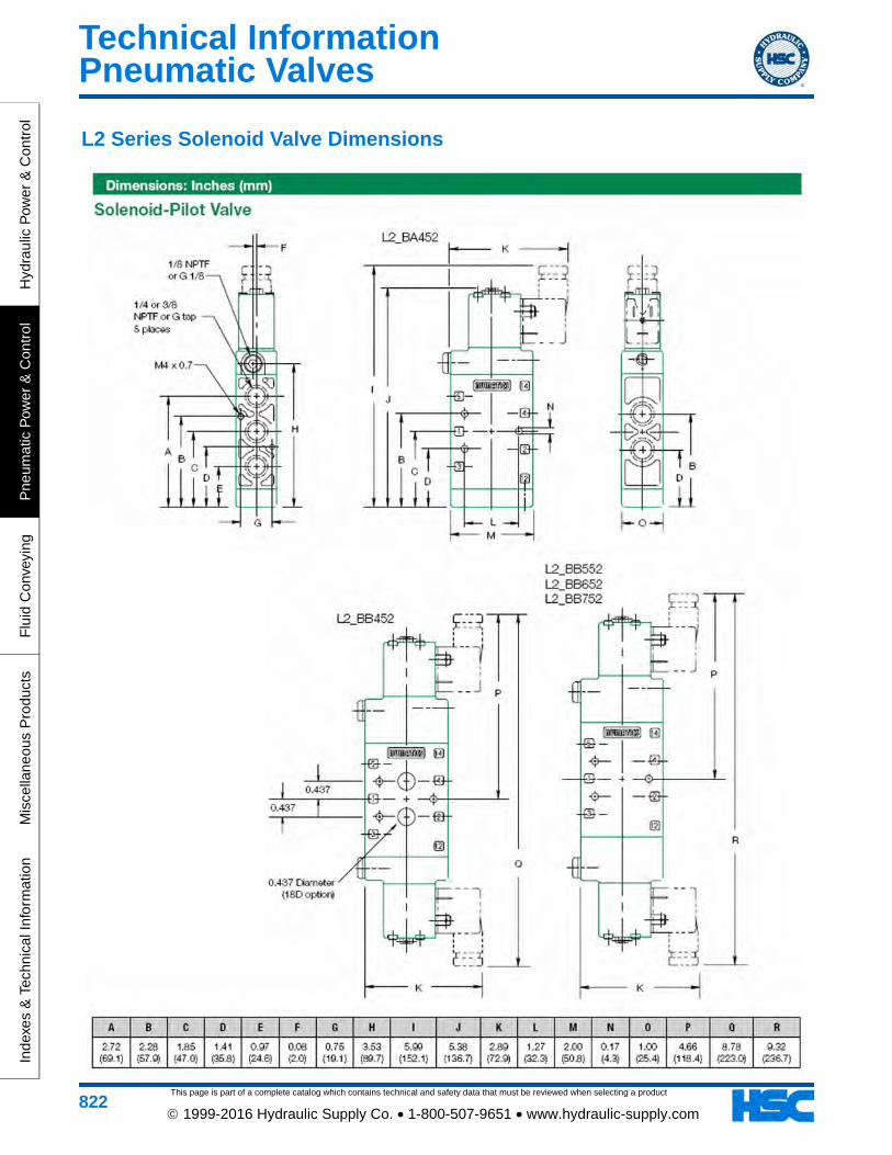
This page is part of a complete catalog which contains technical and safety data that must be reviewed when selecting a product
Pneumatic ValvesTechnical Information
Hyd
raul
ic P
ower
& C
ontr
olP
neum
atic
Pow
er &
Con
trol
Flu
id C
onve
ying
Mis
cella
neou
s P
rodu
cts
Inde
xes
& T
echn
ical
Info
rmat
ion
822 1999-2016 Hydraulic Supply Co. • 1-800-507-9651 • www.hydraulic-supply.com
L2 Series Solenoid Valve Dimensions
Notes
This page is part of a complete catalog which contains technical and safety data that must be reviewed when selecting a product.
__________________________________________________________________________________________
__________________________________________________________________________________________
__________________________________________________________________________________________
__________________________________________________________________________________________
__________________________________________________________________________________________
__________________________________________________________________________________________
__________________________________________________________________________________________
__________________________________________________________________________________________
__________________________________________________________________________________________
__________________________________________________________________________________________
__________________________________________________________________________________________
__________________________________________________________________________________________
__________________________________________________________________________________________
__________________________________________________________________________________________
__________________________________________________________________________________________
__________________________________________________________________________________________
__________________________________________________________________________________________
__________________________________________________________________________________________
__________________________________________________________________________________________
__________________________________________________________________________________________
__________________________________________________________________________________________
__________________________________________________________________________________________
__________________________________________________________________________________________
__________________________________________________________________________________________
__________________________________________________________________________________________
__________________________________________________________________________________________
__________________________________________________________________________________________
Hydraulic P
ower &
Control
Pneum
atic Pow
er & C
ontrolF
luid Conveying
Miscellaneous P
roductsIndexes &
Technical Information
823 1999-2016 Hydraulic Supply Co. • 1-800-507-9651 • www.hydraulic-supply.com

This page is part of a complete catalog which contains technical and safety data that must be reviewed when selecting a product.
Notes
__________________________________________________________________________________________
__________________________________________________________________________________________
__________________________________________________________________________________________
__________________________________________________________________________________________
__________________________________________________________________________________________
__________________________________________________________________________________________
__________________________________________________________________________________________
__________________________________________________________________________________________
__________________________________________________________________________________________
__________________________________________________________________________________________
__________________________________________________________________________________________
__________________________________________________________________________________________
__________________________________________________________________________________________
__________________________________________________________________________________________
__________________________________________________________________________________________
__________________________________________________________________________________________
__________________________________________________________________________________________
__________________________________________________________________________________________
__________________________________________________________________________________________
__________________________________________________________________________________________
__________________________________________________________________________________________
__________________________________________________________________________________________
__________________________________________________________________________________________
__________________________________________________________________________________________
__________________________________________________________________________________________
__________________________________________________________________________________________
__________________________________________________________________________________________
Hyd
raul
ic P
ower
& C
ontr
olP
neum
atic
Pow
er &
Con
trol
Flu
id C
onve
ying
Mis
cella
neou
s P
rodu
cts
Inde
xes
& T
echn
ical
Info
rmat
ion
824 1999-2016 Hydraulic Supply Co. • 1-800-507-9651 • www.hydraulic-supply.com

Notes
This page is part of a complete catalog which contains technical and safety data that must be reviewed when selecting a product.
__________________________________________________________________________________________
__________________________________________________________________________________________
__________________________________________________________________________________________
__________________________________________________________________________________________
__________________________________________________________________________________________
__________________________________________________________________________________________
__________________________________________________________________________________________
__________________________________________________________________________________________
__________________________________________________________________________________________
__________________________________________________________________________________________
__________________________________________________________________________________________
__________________________________________________________________________________________
__________________________________________________________________________________________
__________________________________________________________________________________________
__________________________________________________________________________________________
__________________________________________________________________________________________
__________________________________________________________________________________________
__________________________________________________________________________________________
__________________________________________________________________________________________
__________________________________________________________________________________________
__________________________________________________________________________________________
__________________________________________________________________________________________
__________________________________________________________________________________________
__________________________________________________________________________________________
__________________________________________________________________________________________
__________________________________________________________________________________________
__________________________________________________________________________________________
Hydraulic P
ower &
Control
Pneum
atic Pow
er & C
ontrolF
luid Conveying
Miscellaneous P
roductsIndexes &
Technical Information
825 1999-2016 Hydraulic Supply Co. • 1-800-507-9651 • www.hydraulic-supply.com

This page is part of a complete catalog which contains technical and safety data that must be reviewed when selecting a product.
Notes
__________________________________________________________________________________________
__________________________________________________________________________________________
__________________________________________________________________________________________
__________________________________________________________________________________________
__________________________________________________________________________________________
__________________________________________________________________________________________
__________________________________________________________________________________________
__________________________________________________________________________________________
__________________________________________________________________________________________
__________________________________________________________________________________________
__________________________________________________________________________________________
__________________________________________________________________________________________
__________________________________________________________________________________________
__________________________________________________________________________________________
__________________________________________________________________________________________
__________________________________________________________________________________________
__________________________________________________________________________________________
__________________________________________________________________________________________
__________________________________________________________________________________________
__________________________________________________________________________________________
__________________________________________________________________________________________
__________________________________________________________________________________________
__________________________________________________________________________________________
__________________________________________________________________________________________
__________________________________________________________________________________________
__________________________________________________________________________________________
__________________________________________________________________________________________
Hyd
raul
ic P
ower
& C
ontr
olP
neum
atic
Pow
er &
Con
trol
Flu
id C
onve
ying
Mis
cella
neou
s P
rodu
cts
Inde
xes
& T
echn
ical
Info
rmat
ion
826 1999-2016 Hydraulic Supply Co. • 1-800-507-9651 • www.hydraulic-supply.com

Notes
This page is part of a complete catalog which contains technical and safety data that must be reviewed when selecting a product.
__________________________________________________________________________________________
__________________________________________________________________________________________
__________________________________________________________________________________________
__________________________________________________________________________________________
__________________________________________________________________________________________
__________________________________________________________________________________________
__________________________________________________________________________________________
__________________________________________________________________________________________
__________________________________________________________________________________________
__________________________________________________________________________________________
__________________________________________________________________________________________
__________________________________________________________________________________________
__________________________________________________________________________________________
__________________________________________________________________________________________
__________________________________________________________________________________________
__________________________________________________________________________________________
__________________________________________________________________________________________
__________________________________________________________________________________________
__________________________________________________________________________________________
__________________________________________________________________________________________
__________________________________________________________________________________________
__________________________________________________________________________________________
__________________________________________________________________________________________
__________________________________________________________________________________________
__________________________________________________________________________________________
__________________________________________________________________________________________
__________________________________________________________________________________________
Hydraulic P
ower &
Control
Pneum
atic Pow
er & C
ontrolF
luid Conveying
Miscellaneous P
roductsIndexes &
Technical Information
827 1999-2016 Hydraulic Supply Co. • 1-800-507-9651 • www.hydraulic-supply.com

This page is part of a complete catalog which contains technical and safety data that must be reviewed when selecting a product.
Notes
__________________________________________________________________________________________
__________________________________________________________________________________________
__________________________________________________________________________________________
__________________________________________________________________________________________
__________________________________________________________________________________________
__________________________________________________________________________________________
__________________________________________________________________________________________
__________________________________________________________________________________________
__________________________________________________________________________________________
__________________________________________________________________________________________
__________________________________________________________________________________________
__________________________________________________________________________________________
__________________________________________________________________________________________
__________________________________________________________________________________________
__________________________________________________________________________________________
__________________________________________________________________________________________
__________________________________________________________________________________________
__________________________________________________________________________________________
__________________________________________________________________________________________
__________________________________________________________________________________________
__________________________________________________________________________________________
__________________________________________________________________________________________
__________________________________________________________________________________________
__________________________________________________________________________________________
__________________________________________________________________________________________
__________________________________________________________________________________________
__________________________________________________________________________________________
Hyd
raul
ic P
ower
& C
ontr
olP
neum
atic
Pow
er &
Con
trol
Flu
id C
onve
ying
Mis
cella
neou
s P
rodu
cts
Inde
xes
& T
echn
ical
Info
rmat
ion
828 1999-2016 Hydraulic Supply Co. • 1-800-507-9651 • www.hydraulic-supply.com

Notes
This page is part of a complete catalog which contains technical and safety data that must be reviewed when selecting a product.
__________________________________________________________________________________________
__________________________________________________________________________________________
__________________________________________________________________________________________
__________________________________________________________________________________________
__________________________________________________________________________________________
__________________________________________________________________________________________
__________________________________________________________________________________________
__________________________________________________________________________________________
__________________________________________________________________________________________
__________________________________________________________________________________________
__________________________________________________________________________________________
__________________________________________________________________________________________
__________________________________________________________________________________________
__________________________________________________________________________________________
__________________________________________________________________________________________
__________________________________________________________________________________________
__________________________________________________________________________________________
__________________________________________________________________________________________
__________________________________________________________________________________________
__________________________________________________________________________________________
__________________________________________________________________________________________
__________________________________________________________________________________________
__________________________________________________________________________________________
__________________________________________________________________________________________
__________________________________________________________________________________________
__________________________________________________________________________________________
__________________________________________________________________________________________
Hydraulic P
ower &
Control
Pneum
atic Pow
er & C
ontrolF
luid Conveying
Miscellaneous P
roductsIndexes &
Technical Information
829 1999-2016 Hydraulic Supply Co. • 1-800-507-9651 • www.hydraulic-supply.com

This page is part of a complete catalog which contains technical and safety data that must be reviewed when selecting a product.
Notes
__________________________________________________________________________________________
__________________________________________________________________________________________
__________________________________________________________________________________________
__________________________________________________________________________________________
__________________________________________________________________________________________
__________________________________________________________________________________________
__________________________________________________________________________________________
__________________________________________________________________________________________
__________________________________________________________________________________________
__________________________________________________________________________________________
__________________________________________________________________________________________
__________________________________________________________________________________________
__________________________________________________________________________________________
__________________________________________________________________________________________
__________________________________________________________________________________________
__________________________________________________________________________________________
__________________________________________________________________________________________
__________________________________________________________________________________________
__________________________________________________________________________________________
__________________________________________________________________________________________
__________________________________________________________________________________________
__________________________________________________________________________________________
__________________________________________________________________________________________
__________________________________________________________________________________________
__________________________________________________________________________________________
__________________________________________________________________________________________
__________________________________________________________________________________________
Hyd
raul
ic P
ower
& C
ontr
olP
neum
atic
Pow
er &
Con
trol
Flu
id C
onve
ying
Mis
cella
neou
s P
rodu
cts
Inde
xes
& T
echn
ical
Info
rmat
ion
830 1999-2016 Hydraulic Supply Co. • 1-800-507-9651 • www.hydraulic-supply.com
Notes
This page is part of a complete catalog which contains technical and safety data that must be reviewed when selecting a product.
__________________________________________________________________________________________
__________________________________________________________________________________________
__________________________________________________________________________________________
__________________________________________________________________________________________
__________________________________________________________________________________________
__________________________________________________________________________________________
__________________________________________________________________________________________
__________________________________________________________________________________________
__________________________________________________________________________________________
__________________________________________________________________________________________
__________________________________________________________________________________________
__________________________________________________________________________________________
__________________________________________________________________________________________
__________________________________________________________________________________________
__________________________________________________________________________________________
__________________________________________________________________________________________
__________________________________________________________________________________________
__________________________________________________________________________________________
__________________________________________________________________________________________
__________________________________________________________________________________________
__________________________________________________________________________________________
__________________________________________________________________________________________
__________________________________________________________________________________________
__________________________________________________________________________________________
__________________________________________________________________________________________
__________________________________________________________________________________________
__________________________________________________________________________________________
Hydraulic P
ower &
Control
Pneum
atic Pow
er & C
ontrolF
luid Conveying
Miscellaneous P
roductsIndexes &
Technical Information
831 1999-2016 Hydraulic Supply Co. • 1-800-507-9651 • www.hydraulic-supply.com
This page is part of a complete catalog which contains technical and safety data that must be reviewed when selecting a product.
Notes
__________________________________________________________________________________________
__________________________________________________________________________________________
__________________________________________________________________________________________
__________________________________________________________________________________________
__________________________________________________________________________________________
__________________________________________________________________________________________
__________________________________________________________________________________________
__________________________________________________________________________________________
__________________________________________________________________________________________
__________________________________________________________________________________________
__________________________________________________________________________________________
__________________________________________________________________________________________
__________________________________________________________________________________________
__________________________________________________________________________________________
__________________________________________________________________________________________
__________________________________________________________________________________________
__________________________________________________________________________________________
__________________________________________________________________________________________
__________________________________________________________________________________________
__________________________________________________________________________________________
__________________________________________________________________________________________
__________________________________________________________________________________________
__________________________________________________________________________________________
__________________________________________________________________________________________
__________________________________________________________________________________________
__________________________________________________________________________________________
__________________________________________________________________________________________
Hyd
raul
ic P
ower
& C
ontr
olP
neum
atic
Pow
er &
Con
trol
Flu
id C
onve
ying
Mis
cella
neou
s P
rodu
cts
Inde
xes
& T
echn
ical
Info
rmat
ion
832 1999-2016 Hydraulic Supply Co. • 1-800-507-9651 • www.hydraulic-supply.com

Notes
This page is part of a complete catalog which contains technical and safety data that must be reviewed when selecting a product.
__________________________________________________________________________________________
__________________________________________________________________________________________
__________________________________________________________________________________________
__________________________________________________________________________________________
__________________________________________________________________________________________
__________________________________________________________________________________________
__________________________________________________________________________________________
__________________________________________________________________________________________
__________________________________________________________________________________________
__________________________________________________________________________________________
__________________________________________________________________________________________
__________________________________________________________________________________________
__________________________________________________________________________________________
__________________________________________________________________________________________
__________________________________________________________________________________________
__________________________________________________________________________________________
__________________________________________________________________________________________
__________________________________________________________________________________________
__________________________________________________________________________________________
__________________________________________________________________________________________
__________________________________________________________________________________________
__________________________________________________________________________________________
__________________________________________________________________________________________
__________________________________________________________________________________________
__________________________________________________________________________________________
__________________________________________________________________________________________
__________________________________________________________________________________________
Hydraulic P
ower &
Control
Pneum
atic Pow
er & C
ontrolF
luid Conveying
Miscellaneous P
roductsIndexes &
Technical Information
833 1999-2016 Hydraulic Supply Co. • 1-800-507-9651 • www.hydraulic-supply.com
This page is part of a complete catalog which contains technical and safety data that must be reviewed when selecting a product.
Notes
__________________________________________________________________________________________
__________________________________________________________________________________________
__________________________________________________________________________________________
__________________________________________________________________________________________
__________________________________________________________________________________________
__________________________________________________________________________________________
__________________________________________________________________________________________
__________________________________________________________________________________________
__________________________________________________________________________________________
__________________________________________________________________________________________
__________________________________________________________________________________________
__________________________________________________________________________________________
__________________________________________________________________________________________
__________________________________________________________________________________________
__________________________________________________________________________________________
__________________________________________________________________________________________
__________________________________________________________________________________________
__________________________________________________________________________________________
__________________________________________________________________________________________
__________________________________________________________________________________________
__________________________________________________________________________________________
__________________________________________________________________________________________
__________________________________________________________________________________________
__________________________________________________________________________________________
__________________________________________________________________________________________
__________________________________________________________________________________________
__________________________________________________________________________________________
Hyd
raul
ic P
ower
& C
ontr
olP
neum
atic
Pow
er &
Con
trol
Flu
id C
onve
ying
Mis
cella
neou
s P
rodu
cts
Inde
xes
& T
echn
ical
Info
rmat
ion
834 1999-2016 Hydraulic Supply Co. • 1-800-507-9651 • www.hydraulic-supply.com