Embed Size (px)
Citation preview

ENARCO, S.A.
es
en
fr
de
Manual de instruccionesInstruction manual
Manuel d'instructionsGebrauchsanweisungen
MX-492-0601
PNU
25,
PN
U 4
0, P
NU
50,
PN
U 6
0, P
NU
80
VIBRADORES NEUMÁTICOS
PNEUMATIC POKERS
VIBRATEURS PNEUMATIQUES
PRESSLUFTTRÜTTLER

VIBRADORES NEUMÁTICOS 1
es
PNU 25, PNU 40, PNU 50, PNU 60, PNU 80
ÍNDICE
1 PRÓLOGO 2
2 CARACTERÍSTICAS 3
3 CONDICIONES DE UTILIZACIÓN 3
4 OPERACIÓN Y MANTENIMIENTO 4
4.1 PUESTA EN SERVICIO 4
4.2 CONEXIóN DE LA TOMA DE AIRE AL VIBRADOR NEUMATICO 4
4.3 INSPECCION 4
5 MEDIDAS DE DESGASTE PARA DIÁMETROS Y LONGITUDES EN LAS AGUJAS VIBRANTES 5
6 MANTENIMIENTO PERIODICO 5
6.1 ALMACENAMIENTO 6
6.2 TRANSPORTE 6
7 LOCALIZACION DE AVERIAS 7
8 iNSTRUCCIONES PARA PEDIR REPUESTOS 8
8.1 INSTRUCCIONES PARA PEDIR REPUESTOS 8
8.2 INSTRUCCIONES PARA SOLICITAR GARANTÍAS 8
9 RECOMENDACIONES DE USO 9

VIBRADORES NEUMÁTICOS
es
2 PNU 25, PNU 40, PNU 50, PNU 60, PNU 80
1 PRÓLOGO
Agradecemos su confianza depositada en la marca ENAR Para el máximo aprovechamiento de su equipo de vibración recomendamos que lea y entienda las normas de seguridad, mantenimiento y utilización recogidas en este manual de instrucciones. Las piezas defectuosas deben ser reeemplazadas inmediatamente para evitar problemas mayores. El grado de disponibilidad de la máquina aumentará si sigue las indicaciones de este manual. Para cualquier comentario o sugerencia sobre nuestras máquinas estamos a su total disposición.
VIBRADORES NEUMÁTICOS 3
es
PNU 25, PNU 40, PNU 50, PNU 60, PNU 80
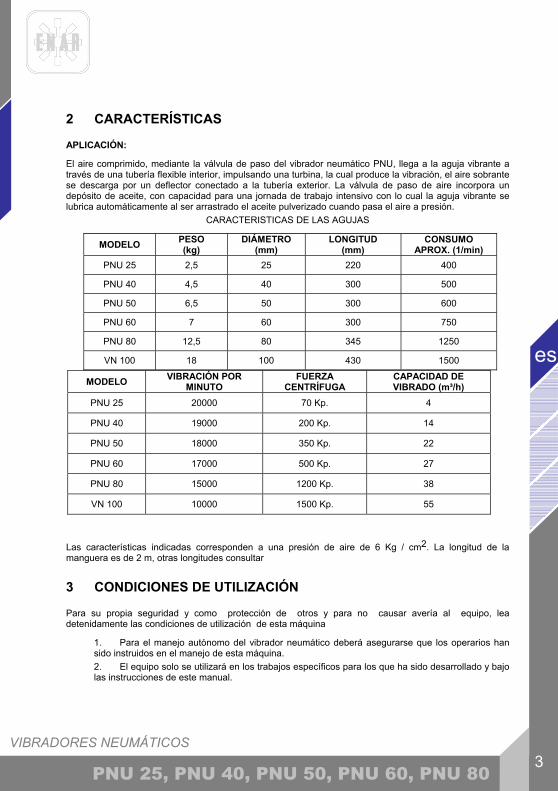
2 CARACTERÍSTICAS
APLICACIÓN:
El aire comprimido, mediante la válvula de paso del vibrador neumático PNU, llega a la aguja vibrante a través de una tubería flexible interior, impulsando una turbina, la cual produce la vibración, el aire sobrante se descarga por un deflector conectado a la tubería exterior. La válvula de paso de aire incorpora un depósito de aceite, con capacidad para una jornada de trabajo intensivo con lo cual la aguja vibrante se lubrica automáticamente al ser arrastrado el aceite pulverizado cuando pasa el aire a presión.
CARACTERISTICAS DE LAS AGUJAS
MODELO PESO (kg)
DIÁMETRO (mm)
LONGITUD (mm)
CONSUMO APROX. (1/min)
PNU 25 2,5 25 220 400
PNU 40 4,5 40 300 500
PNU 50 6,5 50 300 600
PNU 60 7 60 300 750
PNU 80 12,5 80 345 1250
VN 100 18 100 430 1500
Las características indicadas corresponden a una presión de aire de 6 Kg / cm2. La longitud de la manguera es de 2 m, otras longitudes consultar
3 CONDICIONES DE UTILIZACIÓN
Para su propia seguridad y como protección de otros y para no causar avería al equipo, lea detenidamente las condiciones de utilización de esta máquina
1. Para el manejo autónomo del vibrador neumático deberá asegurarse que los operarios han sido instruidos en el manejo de esta máquina. 2. El equipo solo se utilizará en los trabajos específicos para los que ha sido desarrollado y bajo las instrucciones de este manual.
MODELO VIBRACIÓN POR MINUTO
FUERZA CENTRÍFUGA
CAPACIDAD DE VIBRADO (m³/h)
PNU 25 20000 70 Kp. 4
PNU 40 19000 200 Kp. 14
PNU 50 18000 350 Kp. 22
PNU 60 17000 500 Kp. 27
PNU 80 15000 1200 Kp. 38
VN 100 10000 1500 Kp. 55
VIBRADORES NEUMÁTICOS
es
4 PNU 25, PNU 40, PNU 50, PNU 60, PNU 80
3. Antes de trabajar asegúrese que la toma de aire esta conectada a la válvula de paso del vibrador y que esta se encuentra cerrada. 4. Asegúrese que todas las roscas de la aguja están bien apretadas. 5. No trabaje con la manguera con curvas pronunciadas puede obstruir el paso de aire. 6. No tenga la aguja funcionando fuera del hormigón. 7. No limite el movimiento del vibrador durante el trabajo. 8. No pare la aguja durante la operación de vibrado. 9. No opere en la aguja vibrante cuando esta esté en marcha. 10. Reemplace los tubos y puntas desgastados para evitar daños a los componentes internos. 11. Realice el mantenimiento con los tipos y cantidades de lubricantes recomendados. 12. No permita a personal no capacitado o sin experiencia manipular el equipo. 13. Durante el trabajo con este sistema el nivel de ruido puede llegar a 105 dB (98 de presión acústica)
14. La vibración transmitida al usuario no excede de 2,5 m/s2 si se usa adecuadamente (1,1 m /s2 valor medido).
ADICIONALMENTE SE DEBERA RESPETAR LAS ORDENANZAS
VIGENTES EN SU PAIS.
4 OPERACIÓN Y MANTENIMIENTO
4.1 PUESTA EN SERVICIO
En primer lugar leer el punto 3 CONDICIONES DE UTILIZACIÓN
4.2 CONEXIÓN DE LA TOMA DE AIRE AL VIBRADOR NEUMATICO
El vibrador esta diseñado para acoplar de forma rápida y segura la válvula a la toma de aire, haciéndolo así más manejable y ponerlo en uso fácilmente. Modo de conexión:
1. Conectar el acoplamiento de la válvula del vibrador con el acoplamiento de la toma de aire del compresor. 2. Tener en cuenta que la capacidad del compresor sea la adecuada para el consumo de aire de la aguja vibrante.
4.3 INSPECCION 1. Antes de iniciar los trabajos se deberá comprobar el correcto funcionamiento de todos los dispositivos de manejo y seguridad. 2. Inspeccionar regularmente el estado del filtro de entrada de aire a la valvula . Cuando se rompa la manguera exterior repárela o reemplácela para evitar daños en la aguja vibrante. 3. Cuando se detecten piezas desgastadas reemplácelas para evitar daños mayores. 4. Cuando se comprueben defectos que hagan peligrar la manipulación segura, se debe suspender el trabajo y realizar el mantenimiento correspondiente.
VIBRADORES NEUMÁTICOS 5
es
PNU 25, PNU 40, PNU 50, PNU 60, PNU 80
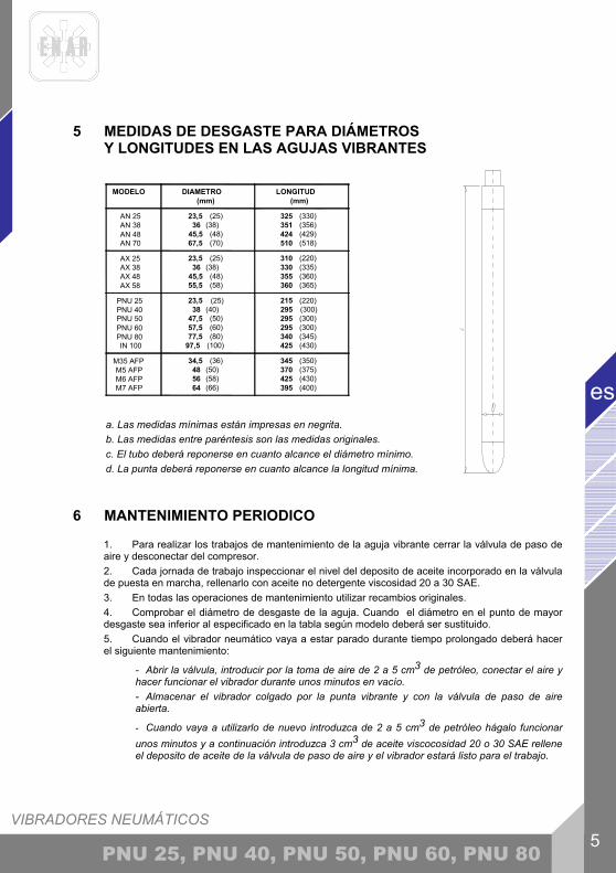
5 MEDIDAS DE DESGASTE PARA DIÁMETROS Y LONGITUDES EN LAS AGUJAS VIBRANTES
a. Las medidas mínimas están impresas en negrita. b. Las medidas entre paréntesis son las medidas originales. c. El tubo deberá reponerse en cuanto alcance el diámetro mínimo. d. La punta deberá reponerse en cuanto alcance la longitud mínima.
6 MANTENIMIENTO PERIODICO
1. Para realizar los trabajos de mantenimiento de la aguja vibrante cerrar la válvula de paso de aire y desconectar del compresor. 2. Cada jornada de trabajo inspeccionar el nivel del deposito de aceite incorporado en la válvula de puesta en marcha, rellenarlo con aceite no detergente viscosidad 20 a 30 SAE. 3. En todas las operaciones de mantenimiento utilizar recambios originales. 4. Comprobar el diámetro de desgaste de la aguja. Cuando el diámetro en el punto de mayor desgaste sea inferior al especificado en la tabla según modelo deberá ser sustituido. 5. Cuando el vibrador neumático vaya a estar parado durante tiempo prolongado deberá hacer el siguiente mantenimiento:
- Abrir la válvula, introducir por la toma de aire de 2 a 5 cm3 de petróleo, conectar el aire y hacer funcionar el vibrador durante unos minutos en vacío. - Almacenar el vibrador colgado por la punta vibrante y con la válvula de paso de aire abierta.
- Cuando vaya a utilizarlo de nuevo introduzca de 2 a 5 cm3 de petróleo hágalo funcionar unos minutos y a continuación introduzca 3 cm3 de aceite viscocosidad 20 o 30 SAE rellene el deposito de aceite de la válvula de paso de aire y el vibrador estará listo para el trabajo.
MODELO DIAMETRO(mm)
LONGITUD(mm)
AN 25 AN 38 AN 48 AN 70
23,5 (25)36 (38)
45,5 (48)67,5 (70)
325 (330)351 (356)424 (429)510 (518)
AX 25 AX 38 AX 48 AX 58
23,5 (25)36 (38)
45,5 (48)55,5 (58)
310 (220)330 (335)355 (360)360 (365)
PNU 25 PNU 40 PNU 50 PNU 60 PNU 80 IN 100
23,5 (25)38 (40)
47,5 (50)57,5 (60)77,5 (80)
97,5 (100)
215 (220)295 (300)295 (300)295 (300)340 (345)425 (430)
M35 AFP M5 AFP M6 AFP M7 AFP
34,5 (36)48 (50)56 (58)64 (66)
345 (350)370 (375)425 (430)395 (400)

VIBRADORES NEUMÁTICOS
es
6 PNU 25, PNU 40, PNU 50, PNU 60, PNU 80
6. Siempre que se realice un mantenimiento en la aguja vibrante siga los siguientes pasos:
- Limpiar las piezas con disolvente y secar todas las partes. - Examinar el estado de los piezas. Si la inspección revela algún desgaste excesivo, las piezas deberán ser reemplazados. - Al montar las piezas colocar las juntas tóricas y aplicar adhesivo sellante en todas roscas. Apretar y limpiar el exceso de sellante. Es importante que queden bien apretadas todas las partes para que el agua no pueda penetrar. Si la pala se ha desgastado y precisa cambiarse lleve el vibrador a un taller autorizado o siga los siguientes pasos:
DESMONTAJE 1. SOLTAR LA VALVULA
1.1. Suelte el cuerpo de la válvula (23) con una llave de 32mm 1.2. Soltar la grupilla (14) para liberar el racord del tubo interior (16) 1.3. Sacar el racord (16 ) de forum que el tubo interior pueda girar al soltar la cabeza de la aguja (12)
2. Soltar la cabeza del vibrador (12) con una llave que se ajuste a los planos (p.e. llave inglesa) para ello sujetar el tubo (3) en un tornillo, giro a derecha 3. Soltar la punta del vibrador (1), con una llave que se ajuste a los planos (p.e. llave inglesa) para ello sujetar el tubo (3) en un tornillo, giro a izquierda. 4. LIBERAR EL MOTOR NEUMÁTICO (5+6+7+8) 4.1. Empujar por el lado de la punta y sacarlo del tubo (3) por el lado de la cabeza 4.2. Sacar la gualdera anterior (5) del eje (7) 4.3. Sacar el cilindro (6) 4.4. Quitar la pala (8). Tener en cuenta la posición de la pala para colocar la nueva en la misma posición. 5. MONTAR LA PALA Y MONTAR LA AGUAJ (proceso inverso): 5.1. colocar PALA EN MISMA POSICION 5.2. colocar cilindró (6) y colocar gualdera posterior (5) sobre el eje (8) con presión EN LA MISMA POSICION QUE ESTABA EN PUNTO 4.2! 5.3. Meter motor neumático (5+6+7+8+9)en el tubo (3) con presión y roscar la punta (1) a izquierdas sobre el tubo (3).Luego rosca la cabeza (12) a derechas sobre el tubo (3). 5.4. Volver a colocar la 16 en posición sobre el cuerp válvula (23) y colocar grupilla (14) sobre la 16.Roscar conjunto puño sobre el cuerpo válvula (23) , rosca a derechas. 7. Después de trabajos de mantenimiento y servicio se deberá montar correctamente todas las partes.
8. Cada 12 meses o con más frecuencia dependiendo de las condiciones de uso se recomienda que sea revisado por un taller autorizado.
6.1 ALMACENAMIENTO 1. Almacenar siempre el vibrador colgado por la aguja y con la válvula abierta en zonas limpias, secas y protegidas, cuando no sea usado por tiempo prolongado.
6.2 TRANSPORTE 1. En vehículos de transporte se deberá asegurar la aguja contra deslizamientos y golpes.
VIBRADORES NEUMÁTICOS 7
es
PNU 25, PNU 40, PNU 50, PNU 60, PNU 80
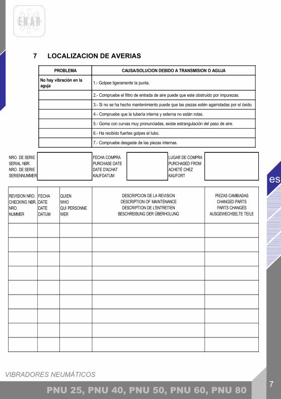
7 LOCALIZACION DE AVERIAS
PROBLEMA CAUSA/SOLUCION DEBIDO A TRANSMISION O AGUJA
No hay vibración en laaguja 1.- Golpee ligeramente la punta.
2.- Compruebe el filtro de entrada de aire puede que este obstruido por impurezas.
3.- Si no se ha hecho mantenimiento puede que las piezas estén agarrotadas por el óxido.
4.- Compruebe que la tubería interna y externa no están rotas.
5.- Goma con curvas muy pronunciadas, existe estrangulación del paso de aire.
6.- Ha recibido fuertes golpes el tubo.
7.- Compruebe desgaste de las piezas internas.
NRO. DE SERIE SERIAL NBR. NRO. DE SERIE SERIENNUMMER
FECHA COMPRA PURCHASE DATE DATE D'ACHAT KAUFDATUM
LUGAR DE COMPRA PURCHASED FROM ACHETÉ CHEZ KAUFORT
REVISION NRO. CHECKING NBR. NRO. NUMMER
FECHA DATE DATE DATUM
QUIEN WHO QUI PERSONNE WER
DESCRIPCION DE LA REVISION DESCRIPTION OF MAINTENANCE DESCRIPTION DE L'ENTRETIEN
BESCHREIBUNG DER ÜBERHOLUNG
PIEZAS CAMBIADAS CHANGED PARTS PARTS CHANGÉS
AUSGEWECHSELTE TEILE
VIBRADORES NEUMÁTICOS
es
8 PNU 25, PNU 40, PNU 50, PNU 60, PNU 80
8 INSTRUCCIONES PARA PEDIR REPUESTOS
8.1 INSTRUCCIONES PARA PEDIR REPUESTOS
1.- En todos los pedidos de repuestos DEBE INCLUIRSE EL CÓDIGO DE LA PIEZA SEGÚN LA LISTA DE PIEZAS. Es recomendable incluir el NÚMERO DE FABRICACIÓN DE LA MÁQUINA. 2.- La placa de identificación con los números de serie y modelo se encuentran en la parte superior de la base motor. 3.- Provéanos con las instrucciones de transporte correctas, incluyendo la ruta preferida, la dirección y nombre completo del consignatario. 4.- No devuelva repuestos a fábrica a menos que tenga permiso por escrito de la misma, todas las devoluciones autorizadas deben enviarse a portes pagados.
8.2 INSTRUCCIONES PARA SOLICITAR GARANTÍAS
1.- La garantía tiene validez por 1 año a partir de la compra de la máquina. La garantía cubrirá las piezas con defecto de fabricación.
- En ningún caso la garantía cubrirá una avería por mal uso del equipo. - La mano de obra y los gastos de envío correrán siempre a cargo del cliente.
2.- En todas las solicitudes de garantía DEBE ENVIARSE LA MÁQUINA A ENARCO, S.A. O TALLER AUTORIZADO, indicando siempre la dirección y nombre completo del consignatario. 3.- El departamento de S.A.T. notificará de inmediato si se acepta la garantía y en el caso de que se solicite se enviará un informe técnico. 4.- No tendrá ningún tipo de garantía cualquier equipo que haya sido previamente manipulado por personal no vinculado a ENARCO, S.A.
NOTA: ENARCO, S.A. se reserva el derecho a modificar cualquier dato de este manual sin previo aviso

VIBRADORES NEUMÁTICOS 9
es
PNU 25, PNU 40, PNU 50, PNU 60, PNU 80
9 RECOMENDACIONES DE USO
1. Seleccionar el tipo de vibrador adecuado según las dimensiones del encofrado, el espacio libre entre las armaduras, la consistencia del hormigón. Consultar el punto como seleccionar el vibrador. Se recomienda siempre tener un vibrador de reserva. 2. Antes de comenzar comprobar que el vibrador está en buenas condiciones y funciona correctamente. Usar los sistemas de protección y seguridad recomendados. 3. Verter el hormigón en la estructura evitando que el hormigón caiga desde gran altura. Se debe verter en el molde o encofrado más o menos nivelado. El espesor de cada capa será inferior a 50 cm, se recomienda entre 30 y 50 cm. 4. Introducir el vibrador verticalmente en la masa sin desplazarlo horizontalmente. No usar el vibrador para arrastrar el hormigón horizontalmente. El vibrador se introduce verticalmente a intervalos regulares, separados de unos a otros una distancia de 8 a 10 veces el diámetro del vibrador (consultar el radio de acción). Mirar al hormigón cuando se vibra para determinar el campo de acción del vibrador. El campo de acción de cada punto de vibración se debe solapar para evitar zonas sin vibrar. La aguja debe penetrar unos 10 cm en la capa anterior para asegurar una buena adhesión entre las diferentes capas. Entre cada capa no deberá transcurrir mucho tiempo para evitar juntas frías. No forzar o empujar el vibrador dentro del hormigón, este podría quedar atrapado en el refuerzo. 5. El tiempo de vibrado en cada punto dependerá del tipo de hormigón, tamaño del vibrador y otros factores. Este tiempo de vibrado puede oscilar entre 5 y 15 segundos. El tiempo es más corto para consistencias fluidas, en estas mezclas un vibrado en exceso puede producir segregación. Un exceso de vibrado podría llegar a producir disgregación. Se considerará el hormigón bien vibrado cuando la superficie se vuelve compacta y brillante y dejan de salir burbujas de aire, también se nota un cambio en el ruido que produce el vibrador. Muchos defectos en estructuras son debidos a una ejecución de la operación de vibrado de forma desordenada y con prisas. 6. No se deberá presionar el vibrador contra armaduras o encofrados. Mantener una distancia de 7 cm como mínimo de las paredes. 7. La aguja se sacará despacio del hormigón y con movimientos hacia arriba y hacia abajo para dar tiempo que el hormigón rellene el agujero dejado por el tubo. La velocidad de extracción del vibrador debe ser aproximadamente 8 cm por segundo. Cuando está prácticamente fuera sacarlo rápidamente para evitar agitación de la superficie. 8. Para vibrar losas, inclinar la aguja para que el contacto superficial con la masa sea mayor. 9. No mantener durante largos periodos el vibrador fuera del hormigón, si no se continúa vibrando pararlo. No usar el vibrador para arrastrar el hormigón horizontalmente. 10. Seguir las instrucciones de mantenimiento del vibrador. Para conseguir una buena estructura de hormigón debemos partir de los componentes adecuados y realizar una vibración de la masa en toda la estructura.
PNEUMATIC POKERS 1
en
PNU 25, PNU 40, PNU 50, PNU 60, PNU 80
INDEX
1 INTRODUCTION 2 2 CHARACTERISTICS 3
2.1 SCOPE 3 3 USAGE CONDITIONS 4 4 OPERATION AND MAINTENANCE 4
4.1 GETTING STARTED 4 4.2 CONNECTION OF THE AIR COUPLING TO THE ADMISSION VALVE: 4 4.3 INSPECTION 5
5 DIMENSIONS OF WEAR FOR DIAMETERS AND LENGTHS OF THE POKERS 5
6 PERIODIC MAINTENANCE 5 6.1 STORAGE 6 6.2 TRANSPORTATION 6
7 LOCATING MALFUNCTIONS 7 8 INSTRUCTIONS TO ORDER SPARE PARTS AND WARRANTIES 8
8.1 INSTRUCTIONS TO ORDER SPARE PARTS 8 8.2 INSTRUCTIONS TO REQUEST WARRANTIES 8
9 RECOMENDATIONS OF USE OF CONCRETE VIBRATOR 9
PNEUMATIC POKERS 2
PNU 25, PNU 40, PNU 50, PNU 60, PNU 80
en
1 INTRODUCTION
Thank you for trusting the ENAR brand For the maximum performance of the equipment, we recommend to read carefully the safety recommendations, maintenance, and usage listed in this manual Defective parts should be replaced immediately to avoid major problems. The effective longevity of the equipment will increase if the manual instructions are followed. We will glad to help you with any comments or suggestions in reference to our equipment.
PNEUMATIC POKERS 3
en
PNU 25, PNU 40, PNU 50, PNU 60, PNU 80
2 CHARACTERISTICS
2.1 SCOPE
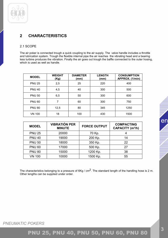
The air poker is connected trough a quick coupling to the air supply. The valve handle includes a throttle and lubrication system. Trough the flexible internal pipe the air reaches the vibrating head and a bearing less turbine produces the vibration. Finally the air goes out trough the baffle connected to the outer hosing, which is used as well as handle.
MODEL WEIGHT (Kg)
DIAMETER (mm)
LENGTH (mm)
CONSUMPTION APPROX. (1/min)
PNU 25 2,5 25 220 400
PNU 40 4,5 40 300 500
PNU 50 6,5 50 300 600
PNU 60 7 60 300 750
PNU 80 12,5 80 345 1250
VN 100 18 100 430 1500
MODEL VIBRATIÓN PER MINUTE FORCE OUTPUT COMPACTING
CAPACITY (m³/h) PNU 25 20000 70 Kp. 4 PNU 40 19000 200 Kp. 14 PNU 50 18000 350 Kp. 22 PNU 60 17000 500 Kp. 27 PNU 80 15000 1200 Kp. 38 VN 100 10000 1500 Kp. 55
The characteristics belonging to a pressure of 6Kg / cm2. The standard length of the handling hose is 2 m. Other lengths can be supplied under order.

PNEUMATIC POKERS 4
PNU 25, PNU 40, PNU 50, PNU 60, PNU 80
en
3 USAGE CONDITIONS
For your own safety, as protection for others, and to avoid damage to the equipment, read carefully the usage recommendations.
1. For the proper use of this device, please assure that the operator has been correctly informed of the content of this manual before using it. 2. This device can be used only under the applications for which it has been designed and according to these safety instructions. 3. Before working, please secure that the air coupling is connected to the handle and that the handle is closed. 4. Please secure also all the threads are properly screwed. 5. Please do not curve the tube excessively so that it could cause an obstruction in the air input. 6. Do not run the machine out of the concrete. 7. Do not impede the movement of the bottle in operation in the concrete mass. 8. Do not stop the poker until the concrete mass is fully vibrated. 9. Do not try to dismount the bottle or any other part of the poker when running. 10.Replace the worn heads and bottles in order not to damage the internal components of the turbine.. 11. Do the maintenance with the recommended types and quantities of lubricants. 12. Do not allow inexperienced or not trained personal to use the poker alone. 13. Proper protective equipment should be used because the acoustic power level of this machine is 105 dB (98 the pressure level)
14. the vibration that transmitted to the operator does not exceed 2,5 m/s2 of acceleration. (1,1 m/s2 obtained value).
FUTHERMORE, THE OPERATOR IS COMPELLED TO RESPECT ADDITIONAL REGULATIONS ENFORCED IN THE COUNTRY OF THE USAGE.
4 OPERATION AND MAINTENANCE
4.1 GETTING STARTED
Read item 3 USAGE CONDITIONS
4.2 CONNECTION OF THE AIR COUPLING TO THE ADMISSION VALVE:
The valve is fitted out with a standard quick-coupling bolt that ensures a quick and safe connection to any compressor or air intake. Connection procedure: 1. Connect the valve coupling of the poker to the coupling of the compressor or the air intake. 2. Make sure that the intake (air central, compressor) is in accordance to the consumption of the poker.

PNEUMATIC POKERS 5
en
PNU 25, PNU 40, PNU 50, PNU 60, PNU 80
4.3 INSPECTION 1. Please ensure before working that all the safety and use devices are effective. 2. Inspect daily the condition of the air filter in the valve. Do not hesitate to change the filter and the outer housing regularly in order to ensure a convenient running. 3. As soon as a defective part is detected, change it to avoid a major damage. 4. As soon as defect that many endanger the running of the device is detected, please do the correspondent repair of maintenance.
5 DIMENSIONS OF WEAR FOR DIAMETERS AND LENGTHS OF THE POKERS
a. The minimum dimensions are bold printed. b. The dimensions into brackets are the original dimensions. c. Replace the housing when reach the minimum diameter. d. Replace the tip when reach the minimum length.
6 PERIODIC MAINTENANCE
1. The poker has to be disconnected from the air intake and the valve has to be in the off position. 2. Check and refill if necessary every day the oil reservoir located in the handle. Always fill the reservoir with a non detergent oil with a viscosity of 20 to 30 SAE. 3. Every maintenance has to be done with original ENAR spare parts. 4. Check the diameter and length of the bottle in order to measure its wearing and its state. The bottle must be replaced when the measures are less than the specified standard ones, the part must be replaced. 5. Before having the poker unused during a long period of time, the following maintenance has to be done:
MODEL DIAMETER(mm)
LENGHT(mm)
AN 25AN 38AN 48AN 70
23,5 (25)36 (38)
45,5 (48)67,5 (70)
325 (330)351 (356)424 (429)510 (518)
AX 25AX 38AX 48AX 58
23,5 (25)36 (38)
45,5 (48)55,5 (58)
310 (220)330 (335)355 (360)360 (365)
PNU 25PNU 40PNU 50PNU 60PNU 80IN 100
23,5 (25)38 (40)
47,5 (50)57,5 (60)77,5 (80)
97,5 (100)
215 (220)295 (300)295 (300)295 (300)340 (345)425 (430)
M35 AFPM5 AFPM6 AFPM7 AFP
34,5 (36)48 (50)56 (58)64 (66)
345 (350)370 (375)425 (430)395 (400)
PNEUMATIC POKERS 6
PNU 25, PNU 40, PNU 50, PNU 60, PNU 80
en
- Open the handle and introduce from 2 to 5 cm3 of petrol with oil in the air intake, then connect the handle to the air source and make the poker run 5 minutes in vacuum. - Always stock the vibrator hanging from the head with the handle open.
- When the poker is about to be used again, repeat the same operation introducing 2 to 5 cm3 of oil only this time with a viscosity of 20-30 SAE in the in the air intake and make the poker run in vacuum for a few minutes so that the oil comes into the head and lubricates the turbine again.
6. Always follow these steps in order to make a proper maintenance: - Clean all the parts with solvent and dry them to remove the solvent excess. - xamine all the parts carefully. The parts that are excessively worn should be replaced. - By re-assembling the parts together, apply sealant on the threads and place the "O" rings, then screw all the threads tight and remove the excess of sealant, after having checked that the ensemble is water-proof.
When the vain is wore and it is necessary change it take it to a technical service or follows the following steps: DISMOUNTING THE VAIN:
1.1 unscrew the valve body(23) with a 32mm end wrench, right thread 1.2 remove circlip (14) to free the internal hose connection rod(16) 1.3 make the connection(16) slide into the valve body(23) to let the internal hose turn when removing the rear cap (12)
2. rear cap: unscrew it (12) with a 45 or 52 mm end wrench holding the tube (3), right thread. 3. cap: unscrew it (1) holding the tube(3) with an end wrench, left thread. 4. freeing the pneumatic motor (5+6+7+8+9):
4.1 push the pneumatic motor from the cap side and make it fall from the tube (3) o the rear cap side 4.2 pull out the front baffle (5) from the shaft (7). 4.3 remove cilinder (6) 4.4 remove vain (8)mind the position of the vain to assemble the new one correctly!
5. MOUNTING THE NEW VAIN (inverting the process): 5.1. insert the new vain in the shaft(7) IN THE RIGHT POSITION!! 5.2. insert the cilinder (6) then front baffle(5) on the shaft (7) IN SAME POSITION THAN IN POINT 4.2 FROM DISMOUNTING THE VAIN! 5.3. replace the pneumatic motor(5+6+7+8+9) with pressure into the tube (3) (1 left thread) in the tube (3).Then screw the rear cap (12 right thread) into the tube(3). 5.4. put the connection(16) in position over valve body (23) and close circlip(14) over(16). 5.5. screw throttle on valve body(23) , right thread.
7. All the parts have to be mounted correctly respecting the diagram of machine type. 8. Every year at least, or depending on the use intensity, the machine has to be sent to an authorized repair specialist.
6.1 STORAGE
Always stock the poker hanging from the head and with the valve opened in a clean and dry area when not be used for a long period of time.
6.2 TRANSPORTATION Make sure the poker won´t suffer any ripping or shock that could cause any damage.
PNEUMATIC POKERS 7
en
PNU 25, PNU 40, PNU 50, PNU 60, PNU 80
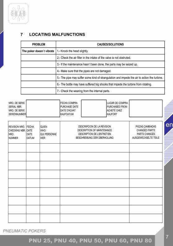
7 LOCATING MALFUNCTIONS
PROBLEM CAUSES/SOLUTIONS
The poker doesn´t vibrate 1.- Knock the head slightly.
2.- Check the air filter in the intake of the valve is not obstruted.
3.- If the maintenance hasn´t been done, the parts may be seized up.
4.- Make sure that the pipes are not damaged.
5.- The pipe may suffer some kind of strangulation and impede the air to action the turbine.
6.- The bottle may have suffered big shocks that impede the turbine from rotating.
7.- Check the wearing from the internal parts.
NRO. DE SERIE SERIAL NBR. NRO. DE SERIE SERIENNUMMER
FECHA COMPRA PURCHASE DATE DATE D'ACHAT KAUFDATUM
LUGAR DE COMPRA PURCHASED FROM ACHETÉ CHEZ KAUFORT
REVISION NRO. CHECKING NBR. NRO. NUMMER
FECHA DATE DATE DATUM
QUIEN WHO QUI PERSONNE WER
DESCRIPCION DE LA REVISION DESCRIPTION OF MAINTENANCE DESCRIPTION DE L'ENTRETIEN
BESCHREIBUNG DER ÜBERHOLUNG
PIEZAS CAMBIADAS CHANGED PARTS PARTS CHANGÉS
AUSGEWECHSELTE TEILE

PNEUMATIC POKERS 8
PNU 25, PNU 40, PNU 50, PNU 60, PNU 80
en
8 INSTRUCTIONS TO ORDER SPARE PARTS AND WARRANTIES
8.1 INSTRUCTIONS TO ORDER SPARE PARTS 1.- All spare parts request must include PART CODE NUMBER AS STATED IN THE PART LIST. We recommend to include ITEM´S MANUFACTURE NUMBER. 2.- The identification plate with manufacture and model number is located in the top part of the motor`s plastic frame. The transmission and pokers have the manufacture number engraved outside. 3.- Let us to know the correct shipping instructions, including the wished route and the address and consignee`s complete name.
8.2 INSTRUCTIONS TO REQUEST WARRANTIES
1.- The warranty is valid 1 year after the purchasing of the machine, The warranty will cover parts with manufacture`s defects. In no case the warranty will cover a malfunction due to improper usage of the equipment. Labour and shipping fees will always be paid by the customer. 2.- In all warranty requests THE MACHINE MUST BE SENT TO ENARCO, S.A. or to an AUTHORIZED SHOP, always including the complete address and name of the consignee. 3.- The Technical Assistance Service will immediately notify you if it accepts the warranty and if requested, it will send a technical report. 4.- The warranty will be void if any equipment has been previously handled by personnel outside of ENARCO, S.A. or not authorized by it.
PNEUMATIC POKERS 9
en
PNU 25, PNU 40, PNU 50, PNU 60, PNU 80
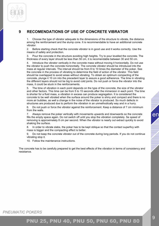
9 RECOMENDATIONS OF USE OF CONCRETE VIBRATOR
1. Choose the type of vibrator adequate to the dimensions of the structure to vibrate, the distance among the reinforcement and the slump cone. It is recommendable to have an additional concrete vibrator. 2. Before starting check that the concrete vibrator is in good use and it works correctly. Use the means of safety and protection. 3. Pour the concrete in the structure avoiding high heights. Try to pour levelled the concrete. The thickness of every layer should be less than 50 cm, it is recomendable between 30 and 50 cm. 4. Introduce the vibrator vertically in the concrete mass without moving it horizontally. Do not use the vibrator to push the concrete horizontally. The concrete vibrator should be introduced into the mass at regular intervals. The interval should be from 8 to 10 times the diameter of the poker. See the concrete in the process of vibrating to determine the field of action of the vibrator. This field should be overlapped to avoid areas without vibrating. To obtain an optimum compacting of the concrete, plunge it 10 cm into the precedent layer to assure a good adherence. The time in vibrating the different layers should not be big to avoid cold joints. Do not push or force the vibrator into the mass, it could be stuck in the reinforcements. 5. The time of vibration in each point depends on the type of the concrete, the size of the vibrator and other factors. This time can be from 5 to 15 seconds after the immersion in each point. The time is shorter for a fluid mass, a vibration in excess can produce segregation. It is considered the concrete to be well vibrated when the surface around the poker is shiny and compact and there is no more air bubbles, as well a change in the noise of the vibrator is produced. So much defects in structures are produced due to perform the vibration in an unmethodically way and in a hurry. 6. Do not push or force the vibrator against the reinforcement. Keep a distance of 7 cm minimum from the walls. 7. Always remove the poker vertically with movements upwards and downwards so the concrete fills the empty space again. Do not switch off until you stop the vibration completely. Se speed of removing is approximately 8 cm per second. When the vibrator is nearly out extract quickly to avoid shaking the surface. 8. In order to vibrate slabs, the poker has to be kept oblique so that the contact superficy with mass is bigger and the compacting effect is better. 9. Do not keep the concrete vibrator out of the concrete during long periods. If you do not continue vibrating stop it. 10. Follow the maintenance instructions.
The concrete has to be carefully prepared to get the best effects of the vibration in terms of consistency and resistance.
VIBRATEURS PNEUMATIQUES 1
fr
PNU 25, PNU 40, PNU 50, PNU 60, PNU 80
INDICE
1 PROLOGUE 2
2 CHARACTERISTICS 3
2.1 APPLICATION 3
3 CONDITIONS D'UTILISATION 4
4 OPERATION AND MAINTENANCE 4
4.1 MISE EN MARCHE 4
4.2 CONNEXION DE LA PRISE D'AIR AU VIBRATEUR PNEUMATIQUE 4
4.3 INSPECTION 4
5 COTES D'USURE POUR LES DIAMETRES ET LONGUEURS DES AIGUILLES VIBRANTES. 5
6 ENTRETIEN PERIODIQUE 5
6.1 ENTREPOSAGE 6
6.2 TRANSPORT 6
7 LOCALISATION PANNES 7
8 L’APPROVISIONNEMENT EN PIECES DETACHEES 8
8.1 INSTRUCTIONS POUR COMMANDER LES PIECES DETACHEES 8
8.2 INSTRUCTIONS POUR FAIRE VALOIR LA GARANTIE 8
9 RECOMMENDATIONS D'UTILISATION DU VIBREUR INTERNE 9

VIBRATEURS PNEUMATICS
fr
2 PNU 25, PNU 40, PNU 50, PNU 60, PNU 80
1 PROLOGUE
Nous vous remercions de la confiance que vous avez déposé en la marque ENAR. Pour profiter de votre appareil ENAR , nous vous recommandons de bien vouloir lire attentivement les recommandations de sécurité, entretien et d'utilisation que regroupe ce manuel d'instructions. Les pièces défectueuses doivent être remplacées pour éviter des problèmes majeurs. Le degré d'efficacité de l'appareil se verra amélioré si les instructions sont suivies comme indiqué ci-après. Nous tenons à votre entière disposition pour répondre à tout type de remarque, question ou suggestion concernant cet appareil ENAR.
VIBRATEURS PNEUMATIQUES 3
fr
PNU 25, PNU 40, PNU 50, PNU 60, PNU 80
2 CHARACTERISTICS
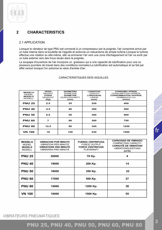
2.1 APPLICATION
Lorsque le vibrateur de type PNU est connecté à un compresseur par la poignée, l'air comprimé arrive par un tube interne dans la bouteille de l'aiguille et actionne un mécanisme de simple turbine.Lorsque la turbine effectue une rotation su elle-même, elle va emmener l'air vers une zone d'échappement et l'air va sortir par un tube externe vers des trous situés dans la poignée. La soupape d'ouverture de l'air incorpore un graisseur qui a une capacité de lubrification pour une ou plusieurs journées de travail dans des conditions normales:La lubrification est automatique et se fait par effet venturi lorsque l'on actionne la valve d'entrée d'air.
CARACTERISTIQUES DEIS AIGUILLES
MODELOMODEL
MODELEMODELL
PESOWEIGHTPOIDS
GEWICHT(Kg)
DIAMETRODIAMETERDIAMETRE
DURCHSCHNITT(mm)
LONGITUDLENGTH
LONGUEURLÄNGE(mm)
CONSUMO APROX.CONSUMPTION APPROX.
CONSOMMATION APPROX.VERBRAUCH CA.
(l/min)
PNU 25 2,5 25 220 400
PNU 40 4,5 40 300 500
PNU 50 6,5 50 300 600
PNU 60 7 60 300 750
PNU 80 12,5 80 345 1250
VN 100 18 100 430 1500
MODELOMODEL
MODELEMODELL
VIBRACION POR MINUTOVIBRATION PER MINUTE
VIBRATIONS PAR MINUTEVIBRIEREN PRO MINUTE
FUERZA CENTRIFUGAFORCE OUTPUT
FORCE CENTRIFUGEFLIEHKRAFT
CAPACIDAD DE VIBRADOCOMPACTING CAPACITYCAPACITÉ DE VIBRATION
VIBRATIONSLEISTUNG(m3/h)
PNU 25 20000 70 Kp. 4
PNU 40 19000 200 Kp. 14
PNU 50 18000 350 Kp. 22
PNU 60 17000 500 Kp. 27
PNU 80 15000 1200 Kp. 38
VN 100 10000 1500 Kp. 55
VIBRATEURS PNEUMATICS
fr
4 PNU 25, PNU 40, PNU 50, PNU 60, PNU 80
3 CONDITIONS D'UTILISATION Pour votre sécurité et celle des autres ainsi que pour ne pas endommager le moteur, lire attentivement et suivre les instructions d'utilisation de cet appareil.
1.- Vérifier que les utilisateurs ont été informés sur les conditions d'utilisation de cet appareil. 2.- Utiliser l'appareil aux fins pour lesquelles il a été conçu et en respectant ses conditions d'utilisation. 3.- Avant de commencer à travailler, s'assurer que l'aiguille est bien connectée à la prise d'air du compresseur et que la soupape d'arrivée d'air est bien fermée. 4.- S'assurer que tous les parties de l'aiguille sont bien sérrées. 5.- Ne pas plier ou courber le tube d'air . 6.- Ne pas faire tourner l'aiguille hors du béton. 7.- Ne pas limiter le mouvement de l'aiguille dans le béton. 8.- Ne pas débrancher l'aiguille avant que l'opération de vibration ne soit achevée. 9.- Ne pas toucher ou essayer de démonter l'aiguille en marche. 10.- Remplacer la tête et la bouteille lorsqu'elles sont usées pour ne pas endommager les composants internes. 11.- Réaliser l'entretien avec les types et quantités de lubrifiant recommendées. 12.- Ne pas laisser l'appareil entre les mains de personnel non autorisé ou non qualifié. 13.- Durant l'utilisation de ce type d'appareil, le bruit produit peut atteindre 105 dB(préssion accoustique de 98dB), l'utilisateur devra donc se protéger avec un casque. 14.- La vibration transmise à l'utilisateur n'excède pas les 2,5m/s2 d'accéleration (valeur mesurée 1.1 m/s2).
RESPECTER ADDITIONNELLEMENT LES NORMES EN VIGUEUR DANS CHAQUE PAYS D'UTILISATION
4 OPERATION AND MAINTENANCE 4.1 MISE EN MARCHE En premier lieu, lire la partie n 3 CONDITIONS D'UTILISATION
4.2 CONNEXION DE LA PRISE D'AIR AU VIBRATEUR PNEUMATIQUE Le vibrateur a été conçu pour s'accoupler de façon facile et rapide à la prise d'air du convertisseur. Connexion:
1.- Connecter la poignée déssinée ci-dessous à la prise de sortie d'air du convertisseur. 2.- Le compresseur doit avoir un débit adéquat à la consommation de l'aiguille branchée.
4.3 INSPECTION 1.- Avant de commencer à travailler, vérifier le correct fonctionnement de tous les dipositifs de sécurité. 2.- Inspecter régulièrement l'état du filtre d'entrée d'air de la poignée.Lorsque le tube extérieur est endommagé, il faut le réparer ou le remplacer pour éviter d'endommager l'aiguille. 3.- Dès que l'on détecte des pièces usées, les remplacer pour éviter des dégâts majeurs. 4.- Dès qu'un défaut est détecté qui puisse rendre la manipulation dangereuse, suspendre le travail en cours et procéder à la réparation ou au remplacement de l'aiguille.
Les caractéristiques indiquées correspondent à une pression de 6 Kg/cm2. La longeur de la poignée est deux metres.

VIBRATEURS PNEUMATIQUES 5
fr
PNU 25, PNU 40, PNU 50, PNU 60, PNU 80
5 COTES D'USURE POUR LES DIAMETRES ET LONGUEURS DES AIGUILLES VIBRANTES.
a. Les cotes d'usure sont imprimées en gras. b. Les cotes entre parenthèses sont celles de la pièce neuve. c. Remplacer le tube dès qu'il atteint le diamètre minimum. d. Remplacer la tête dès qu'elle atteint la longueur minimum.
6 ENTRETIEN PERIODIQUE 1.- Pour réaliser les travaux d'entretien, fermer l'arrivée d'air et débrancher l'aiguille du compresseur. 2.- Après chaque journée de travail, vérifier le niveau d'huile du graisseur incorporé à la poignée et le remplir si nécéssaire d'huile sans détergent de viscosité 20 à 30 SAE. 3.- Dans toutes les opérations d'entretien, utiliser des pièces de rechange d'origine. 4.- Vérifier le diamètre d'usure de l'aiguille.Quand le diamètre de la bouteille au point d'usure maximum est inférieur au diamètre minimum spécificié dans le tableau ci-dessous, elle doit être changée. 5.- Avant d'immobiliser l'aiguille pour une longue période, effectuer les opérations suivantes :
Ouvrir la poignée, introduire 2 à 5 cm3 de pétrole, la brancher au compresseur et faire tourner quelques minutes dans le vide. Suspendre l'aiguille par la pointe et laisser l'arrivée d'air ouverte. Lors de la réutilisation, introduire à nouveau 2 à 5 cm3 de pétrole et faire tourner dans le vide puis rajouter environ 3 cm3 d'huile de viscosité 20 à 30 SAE, remplir à continuation le graisseur et le vibrateur est prêt à être utilisé.
6.- Toujours suivre les pas suivants pour effectuer une opération d'entretien : - Nettoyer les pièces au dissolvent puis bien les sécher.
MODÈLE DIAMÈTRE(mm)
LONGUEUR(mm)
AN 25AN 38AN 48AN 70
23,5 (25)36 (38)
45,5 (48)67,5 (70)
325 (330)351 (356)424 (429)510 (518)
AX 25AX 38AX 48AX 58
23,5 (25)36 (38)
45,5 (48)55,5 (58)
310 (315)330 (335)355 (360)360 (365)
PNU 25PNU 40PNU 50PNU 60PNU 80IN 100
23,5 (25)38 (40)
47,5 (50)56,5 (58)77,5 (80)97,5 (100)
215 (220)290 (295)295 (300)295 (300)340 (345)425 (430)
M3 AFM5 AFM6 AFM7 AF
34,5 (36)48 (50)56 (58)64 (65)
345 (350)370 (375)425 (430)395 (400)

VIBRATEURS PNEUMATICS
fr
6 PNU 25, PNU 40, PNU 50, PNU 60, PNU 80
- Examiner l'état des pièces. Si l'inspection révèle une usure excéssive, procéder au remplacement des pièces en question. - Lors du remontage, replacer les joints thoriques et mettre de la pâte à joint sur toutes les parties filetées.Serrer et enlever l'excés de pâte. S'assurer que toutes les pièces sont bien serrées pour garantir l'étanchéité de l'aiguille.
Si la pale est usée et doit être changée, amener le vibreur à un garage autorisée ou suivez les recommendations suivantes 1.DEMONTER LA PALE:
1.1 dévisser le corps de came (23) avec clef plate de 32mm , pas à droite 1.2 enleve goupille (14) pour libérer le raccord tube interne (16) 1.3 faire glisser le raccord (16) du corps came (23) pour que le tube interne puisse tourner librement lors du démontage de la tête.
2.tête: libérer la tête (12) avec une clef plate de 45 o 52 mm en tenant le tube (3).pas à droite. 3.Pointe: devisser la pointe (1) en tenant le tube(3) avec une clef, pas à gauche. 4.libérer le moteur pneumatique (5+6+7+8+9):
4.1 pousser le moteur pneumatique par le côté de la tête pour le sortir du hors du tube 4.2 arracher la flasque postérieure (5) de l'axe (7). 4.3 retirer le cylindre (6) 4.4 enlever la pale (8) faire attention à la position de la pale pour la remonter corectement!
5.- MONTER LA PALE (procédé inverse): 5.1.- mettre la pale dans l'axe (7) DANS LA MEME POSITION!! 5.2.- mettre le cylindre (6) replacer la flasque postérieure à préssion (5) sur l'axe (7) DANS LA MEME POSITION QU'AU POINT 4.2 DU DEMONTAGE! 5.3.- remettre le moteur pneumatique(5+6+7+8+9)dans le tube(3) à préssion et visser la pointe (1 pas de vis à gauche) au tube (3).Puis visser la tête (12 pas de vis à droite) au tube (3). 5.4.- remettre le raccord(16) en position sobre le corps de câme (23) et placer goupille (14) sur (16). 5.5.-visser la poignée sur le corps de câme (23) , pas de vis à droite.
7.- Après tout type d'opération d'entretien ou de réparation, bien remonter toutes les pièces. 8.- Faire réviser par l'usine ou par un atelier agrée tous les 12 mois ou plus si les conditions d'utilisation l'exigent.
6.1 ENTREPOSAGE
1.- Toujours entreposer suspendu par la tête, l'arrivée d'air ouverte afin que l'eau s'évapore graduellement dans un endroit à l'abri des intempéries.
6.2 TRANSPORT
1.- S'assurer auprès du transporteur ou lors des déplacements que l'aiguille ne sera pas soumise à un mauvais traitement.
VIBRATEURS PNEUMATIQUES 7
fr
PNU 25, PNU 40, PNU 50, PNU 60, PNU 80
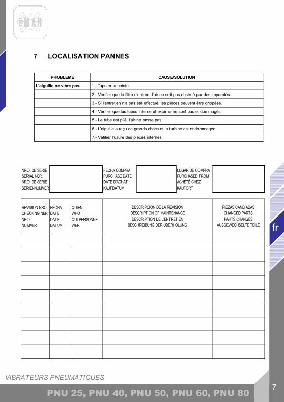
7 LOCALISATION PANNES
PROBLEME CAUSE/SOLUTION
L'aiguille ne vibre pas. 1.- Tapoter la pointe.
2.- Vérifier que le filtre d'entrée d'air ne soit pas obstrué par des impuretés.
3.- Si l'entretien n'a pas été effectué, les pièces peuvent être grippées.
4.- Vérifier que les tubes interne et externe ne sont pas endommagés.
5.- Le tube est plié, l'air ne passe pas.
6.- L'aiguille a reçu de grands chocs et la turbine est endommagée.
7.- Véfifier l'usure des pièces internes.
NRO. DE SERIE SERIAL NBR. NRO. DE SERIE SERIENNUMMER
FECHA COMPRA PURCHASE DATE DATE D'ACHAT KAUFDATUM
LUGAR DE COMPRA PURCHASED FROM ACHETÉ CHEZ KAUFORT
REVISION NRO. CHECKING NBR. NRO. NUMMER
FECHA DATE DATE DATUM
QUIEN WHO QUI PERSONNE WER
DESCRIPCION DE LA REVISION DESCRIPTION OF MAINTENANCE DESCRIPTION DE L'ENTRETIEN
BESCHREIBUNG DER ÜBERHOLUNG
PIEZAS CAMBIADAS CHANGED PARTS PARTS CHANGÉS
AUSGEWECHSELTE TEILE
VIBRATEURS PNEUMATICS
fr
8 PNU 25, PNU 40, PNU 50, PNU 60, PNU 80
8 L’APPROVISIONNEMENT EN PIECES DETACHEES
8.1 INSTRUCTIONS POUR COMMANDER LES PIECES DETACHEES
Inclure dans toute commande de pièces détachées LA REFERENCE DE LA PIECE QUI CORRESPOND A CELLE DE LA VUE ECLATEE AINSI QUE LE NUMERO DE SERIE DE L’APPAREIL. La plaque d’identification avec les numeros de serie et le modèle se trouve sur la partie supérieure de la carcasse en plastique du moteur, sur la transmission et pour ce qui est de l’aiguille, le numero est gravé à l’extérieur, sur la bouteille. Fournir les instructions de transport correctes, en incluant le transporteur et la route désirée ainsi que la direction complète du consignataire. Ne pas retourner de pièces détachées à l’usine à moins d’y être expressement autorisé, sachant que même les retours autorisés doivent être effectués en port dû.
8.2 INSTRUCTIONS POUR FAIRE VALOIR LA GARANTIE
La garantie a une durée de validité de 1 an à partir de la date d’achat de la machine. La garantie couvre les pièces qui présentent un défaut de fabrication. En aucun cas la garantie ne couvrira les dégâts occasionnés par une mauvaise utilisation de l’appareil. La main d’oeuvre et les frais seront toujours à charge du client. Il faut envoyer, pour toute demande, l’appareil à ENARCO, S.A. ou un REPARATEUR AGREE, en indiquant toujours l’adresse et le nom complèt du consignataire. Le département de S.A.V. notifiera immédiatement si la garantie joue et si le client le demande il sera en mesure d’avoir un rapport technique détaillé sur les causes de la panne et sur les opérations à effectuer pour réparer l’appareil. Tout appareil qui aurait été manipulé par un réparateur ou un personnel non agrée par ENARCO, S.A. ne pourra être garanti.
NB : ENARCO, S.A. se reserve le droit de modifier toutes données de ce manuel sans préavis..

VIBRATEURS PNEUMATIQUES 9
fr
PNU 25, PNU 40, PNU 50, PNU 60, PNU 80
9 RECOMMENDATIONS D'UTILISATION DU VIBREUR INTERNE
1. Choisir le vibreur adéquat en fonction des dimensions du cofrage, de l'espace libre entre les armatures, de la consistance du ciment. Se reporter au point "Comment choisir le vibreur ?" Il est recommandé de toujours avoir un vibreur en réserve. 2. Avant de commencer, vérifier que le vibreur est en bon état et fonctionne correctement. Utiliser les systèmes de protection et de sécurité recommandés. 3. Verser le ciment dans la structure en évitant que celui-ci ne tombe de très haut. Il faut verser le ciment dans le moule ou dans le cofrage +/- nivelé. L'épaisseur de chaque couche sera inférieure à 50 cm, il est recommandé entre 30 et 50 cm. 4. Introduire le vibreur verticalement dans la masse sans le déplacer horizontalement. Ne pas utiliser le vibreur pour déplacer le ciment horizontalement. Le vibreur s'introduit verticalement à intervalles réguliers de 8 à 10 fois le diamètre du vibreur (consulter le diamètre d'action). Regarder le ciment quand celui-ci vibre pour déterminer le champ d'action du vibreur. Le champ d'action de chaque point de vibration doit se recouvrir pour éviter les zones non vibrées. L'aiguille de vibration doit pénétrer de 10 cm dans la couche antérieure pour assurer une bonne adhésion entre les différentes couches. Entre chaque couche, il ne faudra pas attendre tropl ongtemps afin d'éviter les joints froids. Ne pas forcer ou pousser le vibreur dans le ciment. Celui-ci pourrait rester coincé dans le renfort. 5. Le temps de vibration de chaque point dépendra du type de ciment, de la taille du vibreur et d'autres facteurs. Ce temps de vibration peut varier entre 5 et 15 secondes. Le temps est plus court pour des consistances fluides. Dans ces mélanges, un vibrage en excès peut produire de la ségrégation. On considérera le ciment bien vibré lorsque la superficie sera compacte et brillante et également lorsqu'on ne verra plus apparaître de bulles d'air. On notera un changement dans le bruit du vibreur. Beaucoup de pannes dans des structures sont dûes à une exécution trop rapide ou désordonnée d'une opération de vibrage. 6. Il ne faudra pas faire une pression du vibreur trop importante contre les armatures ou les cofrages. Maintenir une distance de 7 cm minimum entre le vibreur et les murs. 7. Faire sortir l'aiguille doucement du ciment avec des mouvements de haut vers le bas pour que le ciment bouche le trou laissé par le tube. La vitesse d'extraction du vibreur doit être de 8 cm par seconde. Lorsqu'il est pratiquement sorti, le retirer rapidement pour éviter une agitation de la superficie. 8. Pour la vibration des dalles, incliner l'aiguille afin que le contact superficiel avec la masse soit plus grand. 9. Ne pas laisser trop longtemps le vibreur hors du ciment. Lors des pauses, arrêter le vibreur. Ne pas utiliser le vibreur pour pousser le ciment horizontalement. 10. Suivre les instructions de maintenance du vibreur. Pour arriver à une bonne structure du ciment, il faut avoir de bons composants et réaliser une vibration du béton dans la structure.

PRESSLUFTRÜTTLER 1
de
PNU 25, PNU 40, PNU 50, PNU 60, PNU 80
INHALTSVERZEICHNIS
1 VORWORT 2
2 TECHNISCHE DATEN 3
2.1 EINSATZ 3
3 EINSATZVORAUSSETZUNGEN 4
4 BETRIEB UND WARTUNG 4
4. INSTANDSETZUNG 4
4.2 ANSCHLUSS DES LUFTZUFUHRSTUTZENS AN DEN PRESSLUFTRÜTTLER 4
4.3 ÜBERPRÜFUNG 5
5 ABNUTZUNGSMASSE FÜR DURCHMESSER UND LÄNGEN BEI DEN RÜTTELLANZEN 5
6 REGELMÄSSIGE WARTUNG 6
6.1 LAGERUNG 6
6.2 TRANSPORT 6
7 FEHLERSUCHE 7
8 ANSWEISUNGEN FÜR DIE BESTELLUNG VON ERSATZTEILEN 8
8.1 ANWEISUNGEN FÜR DIE BESTELLUNG VON ERSATZTEILEN 8
8.2 ANWEISUNG FÜR DIE GARANTIEGEWÄHRUNG 8
9 EINSATZVORAUSSETZUNGEN 9
TEILEZERLEGUNG UND TEILEISTE BEILAGE
PRESSLUFTRÜTTLER
de
2 PNU 25, PNU 40, PNU 50, PNU 60, PNU 80
1 VORWORT
Vielen dank für Ihre Vertrauen in die Marke ENAR. Wir empfehlen Ihnen, die Sicherheits- , Instandhaltungs- und anwendungvorschriften in diesem Handbuch zu lesen, damit Sie Ihre ENAR - Anlage voll ausnützen können. Beschädigte Teile müssen umgehend wechselt werden, um größere Probleme zu vermeiden. Die Einsatzbereitschaft der Maschine nimmt zu, wenn Sie dieses Handbuch befolgen. Ihre Anmerkungen und Vorschläge bezüglich unserer Maschinen nehmen wir gern entgegen.
PRESSLUFTRÜTTLER 3
de
PNU 25, PNU 40, PNU 50, PNU 60, PNU 80
2 TECHNISCHE DATEN
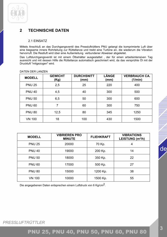
2.1 EINSATZ Mittels Anschluß an das Durchgangsventil des Pressluftrüttlers PNU gelangt die komprimierte Luft über eine biegsame innere Rohrleitung zur Rüttellanze und treibt eine Turbine an, die wiederum die Vibration hervorruft. Die Restluft wird über eine Außenleitung verbundener Abweiser abgeleitet. Das Luftdurchgangsventil ist mit einem Ölbehälter ausgestattet , der für einen arbeitsintensiven Tag ausreicht und mit dessen Hilfe die Rüttellanze automatisch geschmiert wird, da das versprühte Öl mit der Druckluft "mitgezogen" wird. DATEN DER LANZEN
MODELL GEWICHT (Kg)
DURCHSNITT (mm)
LÄNGE (mm)
VERBRAUCH CA. (1/min)
PNU 25 2,5 25 220 400
PNU 40 4,5 40 300 500
PNU 50 6,5 50 300 600
PNU 60 7 60 300 750
PNU 80 12,5 80 345 1250
VN 100 18 100 430 1500
Die angegebenen Daten entsprechen einem Luftdruck von 6 Kg/cm2.
MODELL VIBRIEREN PRO MINUTE FLIEHKRAFT VIBRATIONS
LEISTUNG (m³/h) PNU 25 20000 70 Kp. 4
PNU 40 19000 200 Kp. 14
PNU 50 18000 350 Kp. 22
PNU 60 17000 500 Kp. 27
PNU 80 15000 1200 Kp. 38
VN 100 10000 1500 Kp. 55

PRESSLUFTRÜTTLER
de
4 PNU 25, PNU 40, PNU 50, PNU 60, PNU 80
3 EINSATZVORAUSSETZUNGEN
Lesen Sie bitte zu Ihrer eigenen Sicherheit , zum Schutz anderer Personen und, um zu vermeiden, daß die Anlage beschädigt wird, die Voraussetzungen zur Bedienung dieser Maschine aufmerksam durch.
1. Bitte vergewissern Sie sich hinsichtlich des selbständigen Betriebs der Anlage, daß die an ihr arbeitenden Personen in die Bedienung dieser Maschine eingewiesen worden sind. 2. Die Anlage darf nur im Rahmen jener Arbeiten, für die sie entwickelt worden ist, eingesetzt werden, und lediglich unter Befolgung der Anweisungen dieses Handbuchs. 3. Bitte überzeugen Sie sich vor Arbeitsbeginn, daß die Luftzufuhr an das Durchgangsventil des Rüttlers angeschlossen ist und, daß dieses geschlossen ist. 4. Bitte überzeugen Sie sich vor Arbeitsbeginn, daß alle Gewinde an der Rüttellanze fest angezogen sind. 5. Nicht arbeiten, wenn der Schlauch ausgeprägte Krümmungen aufweist, die die Luftzufuhr unterbrechen können. 6. Lassen Sie die Lanzen nicht länger als 5 Minuten außerhalb des Betons laufen. 7. Behindern Sie nicht die Bewegung des laufenden Rüttlers. 8. Stellen Sie die Lanze während des Betonrüttelns nicht ab. 9. Führen Sie keine Eingriffe an der laufenden Lanze durch. 10. Ersetzen Sie abgenutzte Schläuche, Rohre und Spitzen, um Schäden bei inneren Teilen zu verhindern. 11. Nicht ausgebildetem oder unerfahrenem Personal ist das Bedienen der Anlage zu untersagen. 12. Während der Arbeit mit diesem System kann gelegentlich der zulässige Lärmpegel von 105dB überschritten werden. In diesem Fall muß eine Lärmschutzanlage eingesetzt werden. 13. Aufgrund der Konzeption der Maschine kann die auf den sie bedienenden Arbeiter überghende Vibration 2,5m/s2 überschreiten (1,1 m/s2).
ZUSÄTZLICH MÜSSEN DIE IN IHREM LAND GELTENDEN VORSCHRIFTEN BEFOLGT WERDEN.
4 BETRIEB UND WARTUNG
4.1 INSTANDSETZUNG
Lesen Sie bitte zunächst Punkt 3 EINSATZVORAUSSETZUNGEN
4.2 ANSCHLUSS DES LUFTZUFUHRSTUTZENS AN DEN PRESSLUFTRÜTTLER Die Konstruktion des Rüttlerventils erlaubt ein schnelles und sichers Ankuppeln des Ventils an den Luftzufuhrstutzen und ist damit leicht zu handhaben und in Betrieb zu nehmen. ANSCHLUSSWEISE:
1. Das Kuppelstück des Rüttlerventils mit dem Kuppelstück des Luftzufuhrstutzens des Kompressors verbinden. 2. Die Kapazität des Kompressors muß unbedingt auf den Luftverbrauch der Rüttellanze abgestimmt sein.

PRESSLUFTRÜTTLER 5
de
PNU 25, PNU 40, PNU 50, PNU 60, PNU 80
4.3 ÜBERPRÜFUNG
1. Vor Arbeitsbeginn ist zu überprüfen, ob alle Betriebs- und Sicherheitsvorrichtungen einwandfrei funktionieren. 2. Regelmäßig den Luftzufuhrfilter am Ventil überprüfen.Wenn der Außenschlauch kaputtgeht, dann reparieren oder ersetzen Sie ihn, um Schäden an der Rüttellanze zu vermeiden. 3. Abgenutzte Teile ersetzen, um größere Schäden zu vermeiden. 4. Sobald Fehler auftreten, die den sicheren Umgang der Maschine gefährden, muß die
Arbeit abgebrochen und die entsprechende Instandsetzung unternommen werden.
5 ABNUTZUNGSMASSE FÜR DURCHMESSER UND LÄNGEN BEI DEN RÜTTELLANZEN
a. Die Mindestmaße sind fett gedruckt. b. Die Maße, die in Klammern stehen, sind die Originalmaße. c. Der Schlauch muß ausgetauscht werden, sobald er den Mindestdurchmesser erreicht. d. Die Spitze muß ausgetauscht werden, sobald sie die Mindestlänge erreicht.
MODELL DURCHMESSER(mm)
LÄNGE(mm)
AN 25AN 38AN 48AN 70
23,5 (25)36 (38)
45,5 (48)67,5 (70)
325 (330)351 (356)424 (429)510 (518)
AX 25AX 38AX 48AX 58
23,5 (25)36 (38)
45,5 (48)55,5 (58)
310 (315)330 (335)355 (360)360 (365)
PNU 25PNU 40PNU 50PNU 60PNU 80IN 100
23,5 (25)38 (40)
47,5 (50)56,5 (58)77,5 (80)97,5 (100)
215 (220)290 (295)295 (300)295 (300)340 (345)425 (430)
M3 AFM5 AFM6 AFM7 AF
34,5 (36)48 (50)56 (58)64 (65)
345 (350)370 (375)425 (430)395 (400)
PRESSLUFTRÜTTLER
de
6 PNU 25, PNU 40, PNU 50, PNU 60, PNU 80
6 REGELMÄSSIGE WARTUNG
1. Bei Wartungsarbeiten an der Rüttellanze das Luftdurchgangsventil schließen und den Kompressor abschalten. 2. An jedem Arbeitstag den Ölstand im Ölbehälter des Anlassventils prüfen, nicht schäumendes Öl mit Viskosität 20 bis 30 SAE nachfüllen. 3. Bei allen Wartungsarbeiten Originalersatzteile verwenden. 4. Den Durchmesser der Abnutzung an der Lanze überprüfen.Wenn der Durchmesser an jener Stelle , die die meiste Abnutzung aufweist, unter dem Wert liegt, der in der nach Modellen geordneten Liste aufgeführt ist, muß die Lanze ausgetauscht werden. 5. Falls der Pressluftrüttler längere Zeit nicht benutzt wurde, sind folgende Wartungsarbeiten durchzuführen : Ventil öffnen, durch die Luftzufuhr 2 bis 5 cm3 Petroleum einfüllen, Luft anschließen und den Rüttler einige Minuten im Leerlauf laufen lassen. Den Rüttler an der Spitze aufhängen, bei geöffnetem Luftdurchgangsventil.
Bei erneuter Inbetriebnahme 2 bis 5 cm3 Petroleum einfüllen, ein paar Minuten laufen lassen und anschließend 3 cm3 Öl, Viskosität 20 oder 30 SAE, einfüllen. Den Ölbehälter des Luftdurchgangsventils auffüllen und schon ist der Rüttler einsatzbereit. 6. Bei allen Wartungsarbeiten an der Rüttellanze folgende Schritte befolgen:
- Teile mit Verdünner reinigen und trocken. - Den Zustand der Teile überprüfen. Wenn sich hierbei ein übermäßiger Verschleiß herausstellen sollte, müssen die entsprechenden Teile ausgewechselt werden. - Beim Zusammenbau der Teile die Rundringdichtungen anbringen und alle Gewinde. - Schrauben Sie wieder die Schaltung (16) in das Ventil (23) rechtsdrehend. - Schrauben Sie das Handgriffgesamt in das Ventil (23) rechtsdrehend.
7. Nach Service- und Wartungsarbeiten sind die Teile richtig zusammenzubauen. 8. Je nach Einsatzbedingungen sollte die Anlage alle 12 Monate, oder öfter, von einer
Vertragswerkstatt überprüft werden.
6.1 LAGERUNG 1. Wenn die Lanze für längere Zeit nicht benutzt werden soll, ist sie stets an einem sauberen,
trockenen und geschützten Ort aufzubewahren.
6.2 TRANSPORT
1. In Transportfahrzeugen ist die Lanze stoß- und rutschfest zu sichern.
PRESSLUFTRÜTTLER 7
de
PNU 25, PNU 40, PNU 50, PNU 60, PNU 80
7 FEHLERSUCHE
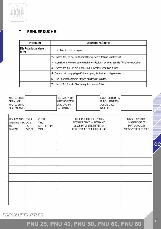
PROBLEM URSACHE / LÖSUNG
Die Rüttellanze vibriertnicht 1.- Leicht an die Spitze klopfen.
2.- Überprüfen, ob der Lufteintrittsfilter verschmutzt und verstopft ist.
3.- Wenn keine Wartung durchgeführt wurde, kann es sein, daß die Teile verrostet sind.
4.- Überprüfen Sie, ob die Innen- und Außenleitungen kaputt sind.
5.- Gummi hat ausgeprägte Krümmungen, die Luft wird abgeklemmt.
6.- Das Rohr ist schweren Stößen ausgesetzt worden.
7.- Überprüfen Sie die Abnutzung der inneren Teile.
NRO. DE SERIE SERIAL NBR. NRO. DE SERIE SERIENNUMMER
FECHA COMPRA PURCHASE DATE DATE D'ACHAT KAUFDATUM
LUGAR DE COMPRA PURCHASED FROM ACHETÉ CHEZ KAUFORT
REVISION NRO. CHECKING NBR. NRO. NUMMER
FECHA DATE DATE DATUM
QUIEN WHO QUI PERSONNE WER
DESCRIPCION DE LA REVISION DESCRIPTION OF MAINTENANCE DESCRIPTION DE L'ENTRETIEN
BESCHREIBUNG DER ÜBERHOLUNG
PIEZAS CAMBIADAS CHANGED PARTS PARTS CHANGÉS
AUSGEWECHSELTE TEILE
PRESSLUFTRÜTTLER
de
8 PNU 25, PNU 40, PNU 50, PNU 60, PNU 80
8 ANSWEISUNGEN FÜR DIE BESTELLUNG VON ERSATZTEILEN
8.1 ANWEISUNGEN FÜR DIE BESTELLUNG VON ERSATZTEILEN
Bei allen Ersatzteibestellungen muss DIE IN DER TEILELISTE AUFGEFÜHRTE BESTELLNUMMER DES ERSATZTEILS angegeben werden. Es wird empfohlen, ebenfalls DIE FABRIKATIONSNUMMER DER MASCHINE anzugeben. Die Kennplakette mit den Serien – und Modellnummern befindet sich auf der Oberseite des Kunststoffgehäuses des Motors, beim Übersetzungsgetriebe und der Lanze steht die Nummer Aussen. Stets die Korrekten Verladungsbedingungen angeben, einschlisslich beföffderungsmittel, Adresse vollständigen Namen des Warenempfängers. Die Ersatzteilrückgabe an die Fabrik darf nur mit schriftlicher Genehmigung derselben erfolgen. Bei allen genehmigten Rückgaben sind die Portokosten zu entrichten.
8.2 ANWEISUNG FÜR DIE GARANTIEGEWÄHRUNG
Die garantiezeit beträgt ab dem Kaufdatum der Maschine 1 Jahr.Die Garantie ertreckt sich auf Teile mit Fabrikationsfehlern. In Keinem Fall ertreckt sich dir Garantie auf Schäden, die auf denunsachgemässen Gebrauch der Maschine zurückzuführen sind. Die Kosten für Techniker und Versand sind Stets vom Kunden zu tragen. Bei allen anträge auf die Garantie IST DIE MASCHINE AN ENARCO, S.A. ODER AN EINE VERTRAGSWERKSTATT EINZUSCHICKEN. Hierbei sin stets die vollständige Adresse und der vollständige Name des warenempfängers anzugeben. Die Kundendienst Abteilung wird unverzügliche Mitteilung darüber ergehen lassen, ob die Garantie übernohmmen wird, und gegebengfalls einen technischen Bericht übermitteln. Für Anlagen, an denen zuvor von personal manipuliert wurde, das nicht im Auftrag von ENARCO, S.A. gehandelt hat, wird keinerlei Garantie übernohmmen.
NB: Zusatzbemerkung: ENARCO, S.A. behält sich das Recht vor, jede Angabe in diesem Handbuch ohne vorherige Mitteilung zu ändern.

PRESSLUFTRÜTTLER 9
de
PNU 25, PNU 40, PNU 50, PNU 60, PNU 80
9 EINSATZVORAUSSETZUNGEN
1- Wählen Sie den Rüttler gemäß den Dimensionen der Schalung oder der Stahlstruktur. Lesen Sie hierzu den Punkt "Den Rüttler wählen". Es wird empfohlen, immer einen Zusatzrüttler auf der Baustelle zu haben, im Falle einer Panne. 2- Vergewissern Sie sich vor Arbeitsbeginn, daß der Rüttler in gutem Zustand ist. Überprüfen Sie, ob alle Betriebs- und Sicherheitsvorrichtungen einwandfrei funktionieren. 3- Pumpen Sie die Betonmasse in die Struktur, wobei Sie vermeiden sollten, daß der Beton aus großer Höhe herunterfällt. Ebnen Sie den Beton in dem Modell oder in der Schalung. Die Dicke jeder Schicht sollte unter 50 cm liegen. Empfohlen wird ein Wert zwischen 30 und 50 cm. 4- Führen Sie den Rüttler senkrecht in die Masse ein, ohne ihn waagrecht zu bewegen. Benützen Sie den Rüttler nicht, um die Betonmasse waagerecht zu ziehen. Der Rüttler wird senkrecht in gleichmäßigen Abständen in die Betonmasse eingeführt (8 oder 10 Mal des Durchmessers der Flasche). Benutzen Sie dazu den Aktionsradius. Den Beton während der Rüttlung beobachten, um das Aktionsfeld des Rüttlers festzulegen. Um ungerüttelte Flächen zu vermeiden, müssen die Entfernungen der Immersionen der Flasche in der Masse kleiner als der Wirkungsradius des Rüttlers sein. Die Anlage muß 10 cm in die vordere Schicht eindringen, damit man eine gute Haftung zwischen den verschiedenen Schichten erhält. Zwischen der Rüttlung der Schichten nicht zuviel Zeit verstreichen lassen, um kalte Dichtungen zu vermeiden. Die Flasche im Beton nicht zwingen oder schieben, sie könnte zwischen den Stahlrohren blockieren. 5- Die Rüttlungszeit in jedem Punkt hängt von der Betonmasse, dem Durchmesser der Flasche und anderen Faktoren ab. Diese Zeit kann zwischen 5 und 15 Sekunden schwanken. Für flüssigen Beton ist die Rüttlungszeit kürzer. Bei diesen Mischungen kann die übermäßige Rüttlung eine Absonderung verursachen. Die Betonmasse ist fertig, wenn die Oberfläche fest und glänzend aussieht oder, wenn keine Luftblasen mehr an die Oberfläche steigen. Sie werden auch eine Änderung des Geraüschs des Rüttlers bemerken. Viele Fehler in Betonstrukturen sind auf eine unordentliche und zu schnelle Rüttlung zurückzuführen. Die Struktur muß in allen ihren Elemnten gleichmäßig gerüttelt worden sein. 6- Drücken Sie die Flasche nicht gegen die Schalung und die Gerüste. 7- Die Anlage muß langsam und senkrecht aus der Betonmasse herausgezogen werden, damit der Beton Zeit hat , das durch die Anlage entstandene Loch wieder zu schließen. Die Geschwindigkeit mit der die Anlage herausgezogen werden sollte, sollte etwa 8 cm / Sekunden betragen. Wenn die Flasche fast draußen ist (letzten 10 cm), muß sie ziemlich schnell rausgezogen werden, um Bewegungen auf der Oberfläche zu vermeiden. 8- Um die Betonplatte (Boden...) zu rütteln, beugen sie die Anlage um einen besseren Kontakt mit der Masse zu schaffen. 9- Lassen Sie den laufenden Rüttler nicht länger als 3 Minuten außerhalb der Betonmasse. Der Rüttler braucht die Kühlung des Betons. Benützen Sie den Rüttler nicht, um die Masse waagerecht zu ziehen. 10- Folgen Sie den Wartungsanweisungen der Maschine. Um eine gute Betonstruktur zu erhalten, müssen Sie die richtigen Komponenten verwenden und die ganze Struktur gleichmäßig rütteln.
PARA REALIZAR CUALQUIER CONSULTA SOBRE LOS DESPIECES Y LISTAS DE PIEZAS DE NUESTRAS MÁQUINAS CONSULTE NUESTRA PÁGINA WEB.
FOR ANY REQUIREMENT ABOUT THE PART LIST OF OUR MACHINES CONSULT OUR WEB PAGE.
POUR CONSULTER TOUS LES RENSEIGNEMENTS DES PIÈCES DETACHEES OU LA LISTE DE NOS MACHINES VOIR NOTRE SITE.
UM DIE VERSCHIEDENE EXPLOSIONSZEICHNUNGEN SO WIE DIE ERSATZTEILLISTEN EINZUSEHEN, BESUCHEN SIE BITTE UNSERE INTERNET-SEITE.
Web: http://www.enar.es

ENARCO, S.A.
ENARCO, S.A. C/Tomás Edison, 19 50014 ZARAGOZA
SPAIN
Tfno. (34) 902 464 090 (34) 976 144 578 Fax (34) 976 471 470
e-mail: [email protected] Web: http://www.enar.es