Embed Size (px)
Citation preview

WARNING:Improper installation, adjustment, altera-tion, service, or maintenance can cause injury or property damage. Refer to this manual. For assistance or additional infor-mation, consult a qualified installer, ser-vice agency, or the gas utility.
FOR YOUR SAFETY• Do not store or use gasoline or other
flammable vapours and liquids in the vi-cinity of this or any other appliance.
• Installation and service must be per-formed by a qualified installer, service agency or the gas utility.
WARNING:If the information in these instructions is not followed exactly, a fire or explosion may result causing property damage, per-sonal injury or death.
• Do not try to light any appliance.• Do not touch any electrical switch; do
not use any phone in your building.• Immediately call your gas supplier from
a neighbor’s phone. Follow the gas supplier’s instructions.
• If you cannot reach your gas supplier, call the fire department.
WHAT TO DO IF YOU SMELL GAS
PART No. 100281151 (17-01)
Installation and service must be performed by a qualifi ed installer, service agency or the gas supplier.
POWER VENTED GAS FIRED WATER HEATER
INSTALLATION ANDOPERATING INSTRUCTIONS
Read these instructions thoroughly before starting
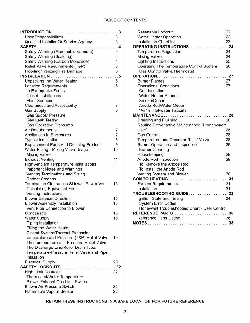
TABLE OF CONTENTS
INTRODUCTION . . . . . . . . . . . . . . . . . . . . . . . . . . . . .3 User Responsibilities 3 Qualified Installer Or Service Agency 3 SAFETY . . . . . . . . . . . . . . . . . . . . . . . . . . . . . . . . . . . .4 Safety Warning (Flammable Vapours) 4 Safety Warning (Scalding) 4 Safety Warning (Carbon Monoxide) 4 Relief Valve Requirements (T&P) 5 Flooding/Freezing/Fire Damage 5 INSTALLATION . . . . . . . . . . . . . . . . . . . . . . . . . . . . . .5 Unpacking the Water Heater 5 Location Requirements 5 In Earthquake Zones Closet Installations Floor Surfaces Clearances and Accessibility 6 Gas Supply 6 Gas Supply Pressure Gas Leak Testing Gas Operating Pressures Air Requirements 7 Appliances In Enclosures 7 Typical Installation 8 Replacement Parts And Deliming Products 9 Water Piping - Mixing Valve Usage 10 Mixing Valves Exhaust Venting 11 High Ambient Temperature Installations 11 Important Notes and Warnings Venting Terminations and Sizing Rodent Screens Termination Clearances Sidewall Power Vent 13 Calculating Equivalent Feet Venting Instructions Blower Exhaust Direction 16 Blower Assembly Installation 16 Vent Pipe Connection to Blower Condensate 18 Water Supply 18 Piping Installation Filling the Water Heater Closed System/Thermal Expansion Temperature and Pressure (T&P) Relief Valve 19 The Temperature and Pressure Relief Valve: The Discharge Line/Relief Drain Tube: Temperature-Pressure Relief Valve and Pipe
Insulation Electrical Supply 20 SAFETY LOCKOUTS . . . . . . . . . . . . . . . . . . . . . . . .22 High Limit Controls 22 Thermostat/Water Temperature Blower Exhaust Gas Limit Switch Blower Air Pressure Switch 22 Flammable Vapour Sensor 22
Resettable Lockout 22 Water Heater Operation 22 Installation Checklist 23 OPERATING INSTRUCTIONS . . . . . . . . . . . . . . . . .24 Temperature Regulation 24 Mixing Valves 24 Lighting Instructions 25 Operating The Temperature Control System 26 Gas Control Valve/Thermostat OPERATION . . . . . . . . . . . . . . . . . . . . . . . . . . . . . . . .27 Burner Flames 27 Operational Conditions 27 Condensation Water Heater Sounds Smoke/Odour Anode Rod/Water Odour “Air” In Hot-water Faucets MAINTENANCE . . . . . . . . . . . . . . . . . . . . . . . . . . . . .28 Draining and Flushing 28 Routine Preventative Maintenance (Homeowner/
User) 28 Gas Control 28 Temperature and Pressure Relief Valve 28 Burner Operation and Inspection 28 Burner Cleaning Housekeeping 29 Anode Rod Inspection 29 To Remove the Anode Rod To Install the Anode Rod Venting System and Blower 30 COMBO HEATING . . . . . . . . . . . . . . . . . . . . . . . . . . .31 System Requirements 31 Installation 31 TROUBLESHOOTING GUIDE . . . . . . . . . . . . . . . . . .32 Ignition State and Timing 34 System Error Codes Honeywell Troubleshooting Chart - User Control REFERENCE PARTS . . . . . . . . . . . . . . . . . . . . . . . .36 Reference Parts Listing 36 NOTES . . . . . . . . . . . . . . . . . . . . . . . . . . . . . . . . . . . .38
RETAIN THESE INSTRUCTIONS IN A SAFE LOCATION FOR FUTURE REFERENCE
– 2 –
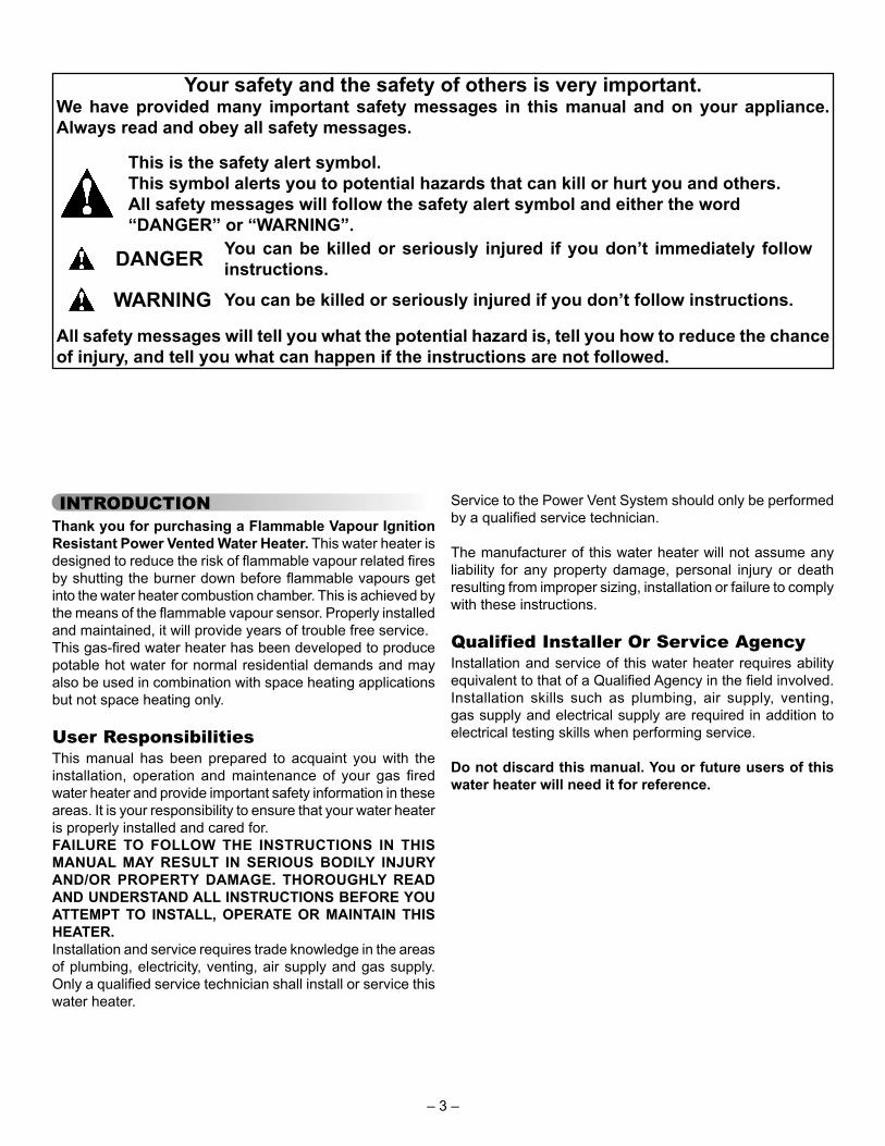
Your safety and the safety of others is very important.We have provided many important safety messages in this manual and on your appliance. Always read and obey all safety messages.
All safety messages will tell you what the potential hazard is, tell you how to reduce the chance of injury, and tell you what can happen if the instructions are not followed.
This is the safety alert symbol.This symbol alerts you to potential hazards that can kill or hurt you and others.All safety messages will follow the safety alert symbol and either the word“DANGER” or “WARNING”.
DANGER
WARNING
You can be killed or seriously injured if you don’t immediately follow instructions.
You can be killed or seriously injured if you don’t follow instructions.
INTRODUCTIONThank you for purchasing a Flammable Vapour Ignition Resistant Power Vented Water Heater. This water heater is designed to reduce the risk of fl ammable vapour related fi res by shutting the burner down before fl ammable vapours get into the water heater combustion chamber. This is achieved by the means of the fl ammable vapour sensor. Properly installed and maintained, it will provide years of trouble free service.This gas-fi red water heater has been developed to produce potable hot water for normal residential demands and may also be used in combination with space heating applications but not space heating only.
User ResponsibilitiesThis manual has been prepared to acquaint you with the installation, operation and maintenance of your gas fi red water heater and provide important safety information in these areas. It is your responsibility to ensure that your water heater is properly installed and cared for.FAILURE TO FOLLOW THE INSTRUCTIONS IN THIS MANUAL MAY RESULT IN SERIOUS BODILY INJURY AND/OR PROPERTY DAMAGE. THOROUGHLY READ AND UNDERSTAND ALL INSTRUCTIONS BEFORE YOU ATTEMPT TO INSTALL, OPERATE OR MAINTAIN THIS HEATER.Installation and service requires trade knowledge in the areas of plumbing, electricity, venting, air supply and gas supply. Only a qualifi ed service technician shall install or service this water heater.
Service to the Power Vent System should only be performed by a qualifi ed service technician.
The manufacturer of this water heater will not assume any liability for any property damage, personal injury or death resulting from improper sizing, installation or failure to comply with these instructions.
Qualified Installer Or Service AgencyInstallation and service of this water heater requires ability equivalent to that of a Qualifi ed Agency in the fi eld involved. Installation skills such as plumbing, air supply, venting, gas supply and electrical supply are required in addition to electrical testing skills when performing service.
Do not discard this manual. You or future users of this water heater will need it for reference.
– 3 –

SAFETY
This water heater is design-certifi ed by CSA International as a Category III, water heater that takes its combustion and dilution air either from the installation area or from air ducted to the unit from the outside.In addition to the installation instructions found in this manual, the water heater must be installed in accordance with provincial codes and the latest edition of "Natural Gas and Propane Installation Code" CSA-B149.1.
Safety Warning (Flammable Vapours)
WARNING
Flammable VapoursFLAMMABLES
FIRE AND EXPLOSION HAZARDCan result in serious injury or death
Do not store or use gasoline or other flammable vapours and liquids in the vicinity of this or any other appliance. Storage of or use of gasoline or other flammable vapours or liquids in the vicinity of this or any other appliance can result in serious injury or death.
There is a risk of property damage, personal injury or death from the by-products of combustion (e.g., fl ue gases), in using fuel-burning appliances such as water heaters. Areas that may not be suitable for water heater installation include those where fl ammable liquids, gasoline, solvents, adhesives etc. are stored. Also not suitable are areas where engine-driven equipment is stored, operated or repaired. Flammable vapour products should not be stored or used near the water heater or air intake. Due to the nature of air movement, fl ammable vapours can be carried some distance from the point of storage. Although the safety system is designed to reduce the risk of fl ammable vapour related fi res, the gas-fi red water heater igniter or burner fl ame can ignite these vapours causing a fl ashback, fi re or explosion, which may result in severe property damage, serious personal injury or death. If fl ammable liquids or vapours have spilled or leaked in the area of the water heater, leave the area immediately and call the fi re department from a neighbor's home. Do not attempt to clean the spill until all ignition sources have been extinguished.
Safety Warning (Scalding)
DANGER
Hot water produced by this appliance can cause severe burns due to scalding. The hazard is increased for young children, the aged or the disabled when water temperatures exceed 52°C (125°F). Use tempering valves, also known as mixing valves, in the hot-water system to reduce the risk of scalding at point-of-use such as lavatories, sinks and bathing facilities (see Figures 11 & 12). Such precautions must be followed when this heater is operated in combination with dishwashing or space heating applications.
Safety Warning (Carbon Monoxide)
Breathing carbon monoxide can cause brain damage or death.Always read and understand instruction manual.
• Install vent system in accordance with codes.• Do not operate water heater if flood damaged.• For operation above 10,100’ (3,079 m), a high
altitude orifice must be installed.• Do not operate if soot buildup is present.• Do not obstruct water heater air intake with
insulating jacket.• Do not obstruct blower air intake.• Do not place chemical vapor emitting products
near water heater.• Gas and carbon monoxide detectors are
available.• No vent damper installation is compatible with
this power vented water heater.
Breathing Hazard - Carbon Monoxide Gas
WARNING
As with all fuel burning equipment, this heater requires an adequate supply of air for combustion. An insuffi cient air supply can result in poor combustion or the re-circulation of the fl ue gases. Such a condition may cause soot build-up and present a fi re hazard. Flow reversal of fl ue gases may cause an increase of carbon monoxide inside of the dwelling that could result in serious bodily harm or death from asphyxiation.
MAKE SURE THE FLOW OF COMBUSTION AIR IS NOT RESTRICTED.
– 4 –

Relief Valve Requirements (T&P)All water heaters must be fi tted with a proper temperature and pressure relief valve. These valves must be certifi ed as meeting the requirements of the "Standard For Relief Valves For Hot Water Supply Systems, ANSI Z21.22/CSA 4.4".
Flooding/Freezing/Fire DamageIf this water heater has been exposed to fl ooding, freezing, fi re or any unusual condition, do not put it into operation until it has been inspected and approved by a qualifi ed service technician. THESE CONDITIONS CAN RESULT IN UNSEEN INTERNAL DAMAGE.
CAUTIONHydrogen gas can be produced in a hot water system served by this heater that has not been used for a long pe-riod of time (generally two (2) weeks or more). Hydrogen gas is extremely fl ammable and can ignite when ex-posed to a spark or fl ame. To reduce the risk of injury un-der these conditions, it is recommended that the hot water faucet be opened for several minutes at the kitchen sink before using any electrical appliance connected to the hot water system. Use caution in opening faucets. If hydrogen is present, there will probably be an unusual sound such as air escaping through the pipe as the water begins to fl ow. There should be no smoking or open fl ame near the faucet at the time it is open.
INSTALLATION Unpacking the Water HeaterImportant: Do not remove any permanent instructions, labels, or the data label from outside of the water heater or on the inside of panels.
• Remove exterior packaging and place installation com-ponents aside.
• Inspect all parts for damage prior to installation and start-up.
• Completely read all instructions before attempting to assemble and install this product.
• Read the “Safety” section of this manual first and then entire manual carefully. If you don’t follow safety rules, the water heater will not operate properly. It could cause DEATH, SERIOUS BODILY INJURY AND/OR PROPERTY DAMAGE. This manual contains instruc-tions for installation, operation, and maintenance of the gas-fired water heater. It also contains warnings throughout the manual that you must read and be aware of. All warnings and instructions are essential to proper operation of the water heater and your safety. Since we cannot put everything on the first few pages, READ ENTIRE MANUAL BEFORE ATTEMPTING TO INSTALL OR OPERATE THE WATER HEATER.
• After installation, dispose of packaging material in the proper manner.
Location RequirementsIMPORTANT:
This water heater must be installed strictly in accordance with the instructions enclosed, and all applicable electrical, fuel and building codes. It is possible that connections to the water heater, or the water heater itself, may develop leaks. It is therefore strongly recommended that the wa-ter heater be installed so that any leakage of the tank or related water piping is directed to an adequate drain in such a manner that it cannot damage the building, fur-niture, fl oor covering, adjacent areas, lower fl oors of the structure or other property subject to water damage. This is particularly important if the water heater is installed in a multi-story building, on fi nished fl ooring or carpeted sur-faces. THE MANUFACTURER WILL NOT ASSUME ANY LIABILITY for damage caused by water leaking from the water heater, pressure relief valve, or related fi ttings. Se-lect a location as centralized within the piping system as possible. In any location selected, it is recommended that a suitable drain pan be installed under the water heater. This pan must limit the water level to a MAXIMUM depth of 45mm (1 3/4 in.) and have a diameter that is a minimum of 50mm (2 in.) greater than the diameter of the water heater. Suitable piping shall connect the drain pan to a properly operating fl oor drain. When used with a fuel-fi red heater, this drain pan must not restrict combustion air fl ow.
45mm max (1 3/4 in.)
AT LEAST 50mm (2 in.) GREATER THAN THE DIAMETER OF THE
WATER HEATER. PIPE TO ADEQUATE
DRAIN
Figure 1
The water heater must be installed indoors in an area not subject to freezing temperatures and in a vertical position on a level surface. Water heaters located in unconditioned spaces (e.g., attics, basements etc.) may require insulation of the water piping, drain piping and venting to protect against condensation. The power vented series of water heaters are designed to vent the products of combustion horizontally through the wall or vertically through the roof. The blower expels the products of combustion by means of certifi ed plastic piping to the outdoors without the need for a conventional chimney.
– 5 –
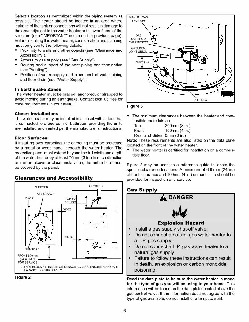
Select a location as centralized within the piping system as possible. The heater should be located in an area where leakage of the tank or connections will not result in damage to the area adjacent to the water heater or to lower fl oors of the structure (see "IMPORTANT" notice on the previous page). Before installing this water heater, consideration and planning must be given to the following details:• Proximity to walls and other objects (see "Clearance and
Accessibility").• Access to gas supply (see "Gas Supply").• Routing and support of the vent piping and termination
(see "Venting").• Position of water supply and placement of water piping
and floor drain (see "Water Supply").
In Earthquake ZonesThe water heater must be braced, anchored, or strapped to avoid moving during an earthquake. Contact local utilities for code requirements in your area.
Closet InstallationsThe water heater may be installed in a closet with a door that is connected to a bedroom or bathroom providing the units are installed and vented per the manufacturer's instructions.
Floor SurfacesIf installing over carpeting, the carpeting must be protected by a metal or wood panel beneath the water heater. The protective panel must extend beyond the full width and depth of the water heater by at least 76mm (3 in.) in each direction or if in an alcove or closet installation, the entire fl oor must be covered by the panel.
Clearances and Accessibility
* DO NOT BLOCK AIR INTAKE OR SENSOR ACCESS. ENSURE ADEQUATE CLEARANCE FOR AIR SUPPLY
FRONT 600mm (24 in.) MIN.
FOR SERVICE
BACKAIR INTAKE *
SENSOR *
SIDES
ALCOVES
SIDES
TOP TO CEILING
CLOSETS
Figure 2
DRIP LEG
MANUAL GAS SHUT-OFF
GASCONTROL/
THERMOSTAT
GROUND-JOINT UNION
76mm (3 in.)
Figure 3
• The minimum clearances between the heater and com-bustible materials are:
Top 200mm (8 in.) Front 100mm (4 in.) Rear and Sides 0mm (0 in.)Note: These requirements are also listed on the data plate located on the front of the water heater.• The water heater is certified for installation on a combus-
tible floor.
Figure 2 may be used as a reference guide to locate the specifi c clearance locations. A minimum of 600mm (24 in.) of front clearance and 100mm (4 in.) on each side should be provided for inspection and service.
Gas SupplyDANGER
Explosion Hazard• Install a gas supply shut-off valve.• Do not connect a natural gas water heater to
a L.P. gas supply.• Do not connect a L.P. gas water heater to a
natural gas supply• Failure to follow these instructions can result
in death, an explosion or carbon monoxide poisoning.
Read the data plate to be sure the water heater is made for the type of gas you will be using in your home. This information will be found on the data plate located above the gas control valve. If the information does not agree with the type of gas available, do not install or attempt to start.
– 6 –

Note: An odourant is added by the gas supplier to the gas used by this water heater. This odourant may fade over an extended period of time. Do not depend upon this odourant as an indication of leaking gas.
This gas piping must be installed in accordance with all provincial requirements and the latest edition of "Natural Gas and Propane Installation Code" CSA-B149.1.
Use properly sized gas piping and to ensure full gas input and a properly sized gas supply regulator to ensure adequate gas supply pressure. The supply piping and regulator must be large enough to satisfy the requirements of all appliances connected to the gas service and when all appliances are operating simultaneously. Undersize piping and insuffi cient pressure can restrict the gas fl ow causing the water heater to perform poorly. Improperly sized piping may pose a safety hazard.
Note: When installing gas piping, apply sealing compounds approved for use with natural and propane gas.1. Install a readily accessible manual shut-off valve in the
gas supply line as required "Natural Gas and Propane Installation Code" CSA-B149.1. The owner/operator must be shown the location of this valve and be given instructions on how to use it to shut off the gas to the heater.
2. Install a drip leg (if not already incorporated as part of the water heater) as shown. The drip leg must be no less than 76mm (3 in.) long for the accumulation of dirt, foreign material, and water droplets.
3. Install a ground joint union, or other approved gas dis-connect, between the gas control/thermostat and the manual shut-off valve. This is to allow easy removal of the gas control/thermostat.
4. Turn the gas supply on and check for leaks. Use a chlo-ride-free soap and water solution (bubbles forming indi-cate a leak) or other approved method.
Gas Supply PressureImportant: The gas supply pressure must not exceed the maximum supply pressure as stated on the water heater's data plate.
Gas Leak TestingImportant: This water heater and its gas connection must be leak tested before placing the appliance in operation.• If the code requires the gas lines to be tested at a pres-
sure exceeding 14 in. w.c. (3.5 kPa), the water heater and its manual shut-off valve must be disconnected from the gas supply piping system and the line capped.
• If the gas lines are to be tested at a pressure less than 14 in. w.c. (3.5 kPa), the water heater must be isolated from the gas supply piping system by closing its manual shut-off valve.
WARNINGExposure to a higher gas supply pressure may cause damage to the control, resulting in explosion or fi re. Consult your local gas supplier and gas authorities. DO NOT PUT INTO SERVICE IF OVER-PRESSURIZATION HAS OCCURRED.
Gas Operating PressuresThe gas supply pressure and burner manifold pressure is listed on the data plate located on the front of the heater above the gas control/thermostat. Ensure the gas supply pressure to the water heater and the burner manifold pressure are properly adjusted while all appliances are in operation. Refer to Figure 35 for Honeywell Gas Control/Thermostat Details.
Rated Manifold Pressure.
in. w.c. (kPa)
Min. Manifold Pressure.
in. w.c. (kPa)
Max. Manifold Pressure.
in. w.c. (kPa)10 (2.48) 9.2 (2.28) 10.2 (2.53)4 (0.99) 3.6 (0.89) 4.4 (1.09)
U.L. and CSA recognized fuel gas and Carbon Monoxide (CO) detectors are recommended in all applications and should be installed using the manufacturer's instructions and local codes, rules or regulations.
Air RequirementsA gas water heater cannot operate properly without the correct amount of air for combustion. Do not install in a confi ned area such as a closet, unless you provide adequate air supply. Never obstruct the fl ow of dilution/ventilation air. If you have any doubts or questions at all, call your gas supplier. Failure to provide the proper amounts of air can result in a fi re or explosion and cause death, serious bodily injury, or property damage. The combustion and dilution air inlets are shown in Figure 5.
Important: Air must not come from a corrosive atmosphere. Any failure due to corrosive elements in the atmosphere is excluded from warranty coverage.Installations in or for certain places including, but not limited to, those listed below may require outdoor air for combustion and dilution to reduce the risk of chemical exposure. In these cases it is probably necessary to install a Power Direct Vent (PDV) water heater:• Beauty shops, Photo processing labs• Buildings with indoor pools• Water heaters installed in some laundry, hobby or craft
rooms• Water heaters installed near chemical storage areasIn some cases, isolation of the water heater from corrosive environments may be required.
Appliances In EnclosuresIf the water heater is installed in an enclosure ensure an air supply is provided as required by the current edition of "Natural Gas and Propane Installation Codes" CSA-B149.1.
– 7 –

Typical Installation
1. Vent Termination Elbow with Rodent Screen
2. *Vent Pipe3. *Vent Pipe Coupling (if required)4. *Vent Pipe Elbow (long radius)5. Limit Switch (see Figure 9)6. T&P Valve7. Diptube8. Baffle Assembly9. * Discharge Pipe10. Gas Control Valve/Thermostat
(Honeywell)11. Gas Valve Electronic Control
Module And Cover (Honeywell)12. Drain Valve13. Outer Gas Door14. Manifold Door Assembly (behind
outer door) (see Figures 6 & 7)15. *Floor Drain16. *Metal Drain Pan17. Flammable Vapour Sensor (under
cover) (see Figure 8)
18. **Combo Heating System Return Inlet (Optional)
19. Air Inlet Snorkel20. **Combo Heating System Supply
Outlet (Optional)21. Blower with Power Cord (see
Figure 9)22. Air Switch (inside box) (see Figure
9)23. Junction Box (see Figure 9)24. Junction Box Cover (see Figure 6)25. Air Tubing (see Figure 9)26. Rubber Coupling27. Gear Clamp28. Flue Collector29. Hot-Water Outlet Nipple30. Anode (under cap)31. Cold-Water Inlet Nipple32. Flexible Manifold Tube (see
Figures 6 & 7)33. Viewport (see Figures 6 & 7)34. Flame Sensor Rod (see Figures 6
& 7)35. Gas Orifice (see Figures 6 & 7)
36. Sheet Metal Burner (see Figures 6 & 7)
37. Gas Manifold (see Figures 6 & 7)38. Hot-Surface Igniter (see Figures 6
& 7)39. Manifold Door Gasket (see Figures
6 & 7)40. Manifold Door (see Figures 6 & 7)41. Two Piece Grommet With Clip
(see Figures 6 & 7)42. *Inlet Water Shut-off Valve43. *Gas Supply*44. *Main Manual Gas Shut-off Valve45. *Ground Joint Union (gas connec-
tion)46. *Sediment Trap/Dirt Leg47. *Union (water connection)48. Rating Plate49. ***Control Harness50. *Thermal Expansion Tank
(required for all closed systems)
Front View Rear ViewFigure 4 Figure 5
1
6
9
10
12
13
16
17
20
18
2 3 4
21
27
21
8
7
14
11
15
26
43
44
45
46
49
48
19
21 29
3130
Combustion Air Inlets
29
42
47
4750
28
Dilution Air Inlets
– 8 –

3234
36
3338
39
37
35
4041
Natural gas and Propane main burner with igniter assembly for 40k to 50k Btu/hr models
Figure 6
32 34
36
3338
39
37
35
4041
Natural gas and Propane main burner with igniter assembly for 60k to 75k Btu/hr models
Figure 7
17
Figure 8
25
23
24
22
5
26
27
Figure 9
Vacuum relief valve install per local codes (not supplied with heater).
Figure 10
* Items not supplied with the water heater** The side recirculation loop connections may not be used
as the primary water inlet and outlet connections. For your convenience, plugs are installed in these fittings at the factory. Remove these plugs if needed for your specific installation. Otherwise (as with all connections) check for leaks while filling the tank with water and after completing the installation.
*** Caution: harness has 120 VAC present during opera-tion.
Replacement Parts And Deliming ProductsReplacement parts and recommended delimer may be ordered through authorized servicers or distributors. When ordering parts, provide complete model and serial numbers (see rating plate), quantity and name of part desired. Standard hardware items may be purchased locally.
– 9 –

Water Piping - Mixing Valve Usage
MIXING VALVESHUT-OFF
VALVE
SUGGESTED PIPING ARRANGEMENT FOR TOP CONNECTIONS
COLD-WATER INLET
TEMPERED POTABLE WATER
DISCHARGE PIPE (DO NOT CAP OR PLUG)
GAS SUPPLY
TEMPERATURE-PRESSURE RELIEF VALVE
DRAIN VALVE
METALDRAIN PAN
150mm (6”)MAX. AIRGAP*
TO SUITABLE DRAIN
CERTAIN MODELS ARE
EQUIPPED WITH SIDE PLUMBING
CONNECTIONS FOR SPACE HEATING.
THE HOT AND COLD FITTING ASSEMBLIES
(PART #9001262) CAN BE ORDERED
THROUGH AN AUTHORIZED
DEALER
* NOTE: THE T&P VALVE CAN BE PIPED DIRECTLY TO THE DRAIN
Figure 11
This appliance has been design certifi ed as complying with CSA Standard for water heaters and certain models with side plumbing connections are considered suitable for Water (Potable) Heating and Space Heating.The water heater should not be subjected to excessive water pressure fl uctuations and should not be subjected to an operating pressure greater than 80 psi. If this occurs, a pressure-reducing valve with a bypass should be installed in the cold-water inlet line. This should be placed on the supply to the entire house in order to maintain equal hot and cold water pressure.
MIXING VALVESHUT-OFF
VALVE
SUGGESTED PIPING ARRANGEMENT FOR TOP CONNECTIONS
COLD-WATER INLET
TEMPERED POTABLE WATER
DISCHARGE PIPE (DO NOT CAP OR PLUG)
GAS SUPPLY
NON-TEMPERED WATER SUPPLY
NON-TEMPERED WATER RETURN
TEMPERATURE-PRESSURE RELIEF VALVE
DRAIN VALVE
METALDRAIN PAN
150mm (6”)MAX. AIRGAP*
TO SUITABLE DRAIN
* NOTE: THE T&P VALVE CAN BE PIPED DIRECTLY TO THE DRAIN
Figure 12
Mixing ValvesWater heaters are intended to produce hot water. Water heated to a temperature which satisfi es space heating, clothes washing, dish washing, and other sanitizing needs can scald and cause permanent injury upon contact. Short repeated heating cycles caused by small hot-water uses can cause temperatures at the point of use to exceed the water heater’s temperature setting by up to 11C° (20F°).Some people are more likely to be permanently injured by hot water than others. These include the elderly, children, the infi rm and the physically/mentally disabled. Table 3 shows the approximate time-to-burn relationship for normal adult skin. National plumbing code requirements limit the temperatures of certain fi xtures in the home. Local codes may have additional requirements. In addition to these requirements, if anyone using hot water in your home fi ts into one of these groups, then you must take special precautions. In addition to using the lowest possible temperature setting that satisfi es your hot water needs, a means such as a Mixing Valve, should be used at the hot water taps used by these people or at the water heater. Mixing valves are available at plumbing supply or hardware stores. Consult a Qualifi ed Installer or Service Agency. Follow mixing valve manufacturer’s instructions for installation of the valves (see Figures 11 & 12). Before changing the factory setting on the thermostat, read the “Temperature Regulation” section in this manual.
– 10 –

Exhaust VentingThis heater is designed to exhaust the products of combustion (fl ue gases) to the outdoors using a sealed piping system. Table 1 lists the allowable vent materials and sizing information. Figure 16 shows the general venting layout while Figures 17-19 show various end termination details and clearances. Connection of the venting piping to the blower is shown in Figures 21-25.
Correct installation of the venting system is essential to the safe and effi cient operation of this water heater. Vent piping must be installed in accordance with all applicable national and provincial codes. All installations shall meet the requirements as stated in the latest edition of the "Natural Gas and Propane Installation Codes" CSA-B149.1.
STREET ELBOW NORMAL ELBOW
150mm(6 in.) min.
BACK TO BACK ELBOWS
90° LONG SWEEP ELBOW (LESS RESTRICTIVE)
90° SHORT SWEEP ELBOW (MORE RESTRICTIVE)
PREFERRED PRACTICE
PREFERRED PRACTICESNOT RECOMMENDED
Figure 13
Note: The information provided in Figure 13 is intended as a guideline for good vent installation practices only and is not intended to restrict venting options beyond those restrictions established by the latest edition of the "Natural Gas and Propane Installation Codes" CSA-B149.1 or any applicable local and provincial codes.
High Ambient Temperature InstallationsThis heater requires room air to lower the fl ue gas temperatures before the gases pass through the vent system. The dilution air inlets are located on the rear of the blower assembly (see Figures 5 & 21). As the room temperature rises, the ability to lower the fl ue gases lessens so special attention to the choice of venting material is required. Establishing the ambient temperatures where the heater and the venting is installed is very important, especially in regions with warmer climates or any region that experiences hot summers. Ambient conditions hotter than 43°C (110°F) require that the venting material be either CPVC or polypropylene. Areas that can experience high ambient environments include closets, alcoves, areas under staircases, attics especially in metal roofed buildings, areas with restricted air movement, rooms with large solar gains, metal sheds, industrial or commercial enterprises and venting systems exposed to direct sunlight. For high temperature environments, obtain high limit switch upgrade Kit # 9008306015 and use the higher rated vent piping.
Important Notes and Warnings• This heater is certified to be installed using Schedule
40 PVC or CPVC or polypropylene plastic vent material. All jurisdictions require that this material is approved to ULC S636. Only use approved material. All venting mate-rial and components must be joined with the approved primer/cleaner and solvent cement.
• Do not common vent this heater with any other appli-ance.
• During operation the plastic piping will expand as it heats up and contract as it cools down. This is normal for this type of venting. Rigidly fastening the vent piping can cause undue stress that may result in the cracking or fracturing the vent piping material. A fracture of the vent-ing pipe may pose a serious safety hazard. To prevent stressing of the vent system, all hangers and supports must allow the vent piping freedom to move.
• Use long sweep elbows wherever possible. Closely-coupled elbows and short radius elbows can reduce the venting capacity.
• All power vented water heaters generate a certain amount of operational noise. In order to minimize noise transmission to the support structure, it is recommended to use isolation pads between the pipe hangers and the vent pipe.
• Most power vent installations develop some condensa-tion in the vent piping. When using long runs of venting or when the venting passes through cold or unheated areas, considerable amounts of condensate from the flue gases can develop. Provision must be made for the con-densate to drain freely from the system or to be collected in a condensate trap(s) that can be drained. Damage or fracture of the vent piping may occur if the condensate is allowed to collect and freeze. Pooling of condensate can restrict airflow and can cause nuisance failures of the system.
– 11 –
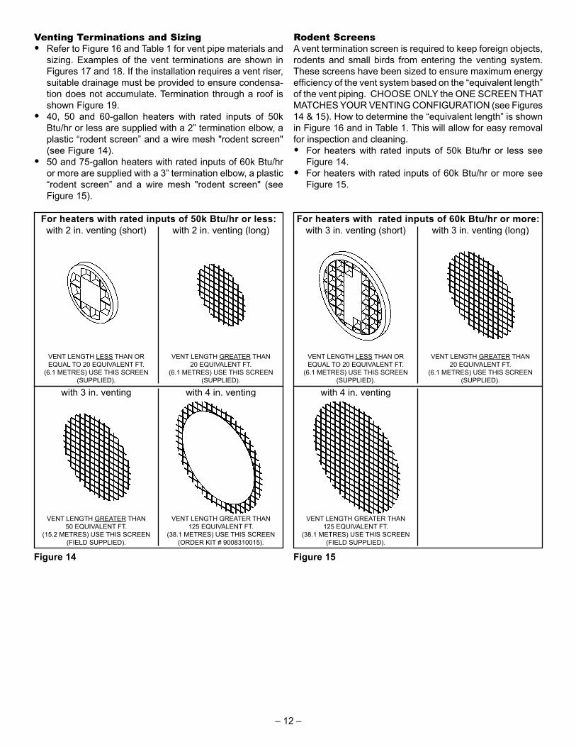
Venting Terminations and Sizing• Refer to Figure 16 and Table 1 for vent pipe materials and
sizing. Examples of the vent terminations are shown in Figures 17 and 18. If the installation requires a vent riser, suitable drainage must be provided to ensure condensa-tion does not accumulate. Termination through a roof is shown Figure 19.
• 40, 50 and 60-gallon heaters with rated inputs of 50k Btu/hr or less are supplied with a 2” termination elbow, a plastic “rodent screen” and a wire mesh "rodent screen" (see Figure 14).
• 50 and 75-gallon heaters with rated inputs of 60k Btu/hr or more are supplied with a 3” termination elbow, a plastic “rodent screen” and a wire mesh "rodent screen" (see Figure 15).
with 3 in. venting with 4 in. venting
VENT LENGTH GREATER THAN 50 EQUIVALENT FT.
(15.2 METRES) USE THIS SCREEN (FIELD SUPPLIED).
VENT LENGTH GREATER THAN 125 EQUIVALENT FT.
(38.1 METRES) USE THIS SCREEN (ORDER KIT # 9008310015).
with 2 in. venting (short) with 2 in. venting (long)For heaters with rated inputs of 50k Btu/hr or less:
VENT LENGTH LESS THAN OR EQUAL TO 20 EQUIVALENT FT.
(6.1 METRES) USE THIS SCREEN (SUPPLIED).
VENT LENGTH GREATER THAN 20 EQUIVALENT FT.
(6.1 METRES) USE THIS SCREEN (SUPPLIED).
Figure 14
Rodent ScreensA vent termination screen is required to keep foreign objects, rodents and small birds from entering the venting system. These screens have been sized to ensure maximum energy effi ciency of the vent system based on the “equivalent length” of the vent piping. CHOOSE ONLY the ONE SCREEN THAT MATCHES YOUR VENTING CONFIGURATION (see Figures 14 & 15). How to determine the “equivalent length” is shown in Figure 16 and in Table 1. This will allow for easy removal for inspection and cleaning.• For heaters with rated inputs of 50k Btu/hr or less see
Figure 14.• For heaters with rated inputs of 60k Btu/hr or more see
Figure 15.
with 4 in. venting
VENT LENGTH GREATER THAN 125 EQUIVALENT FT.
(38.1 METRES) USE THIS SCREEN (FIELD SUPPLIED).
with 3 in. venting (short) with 3 in. venting (long)For heaters with rated inputs of 60k Btu/hr or more:
VENT LENGTH LESS THAN OR EQUAL TO 20 EQUIVALENT FT.
(6.1 METRES) USE THIS SCREEN (SUPPLIED).
VENT LENGTH GREATER THAN 20 EQUIVALENT FT.
(6.1 METRES) USE THIS SCREEN (SUPPLIED).
Figure 15
– 12 –
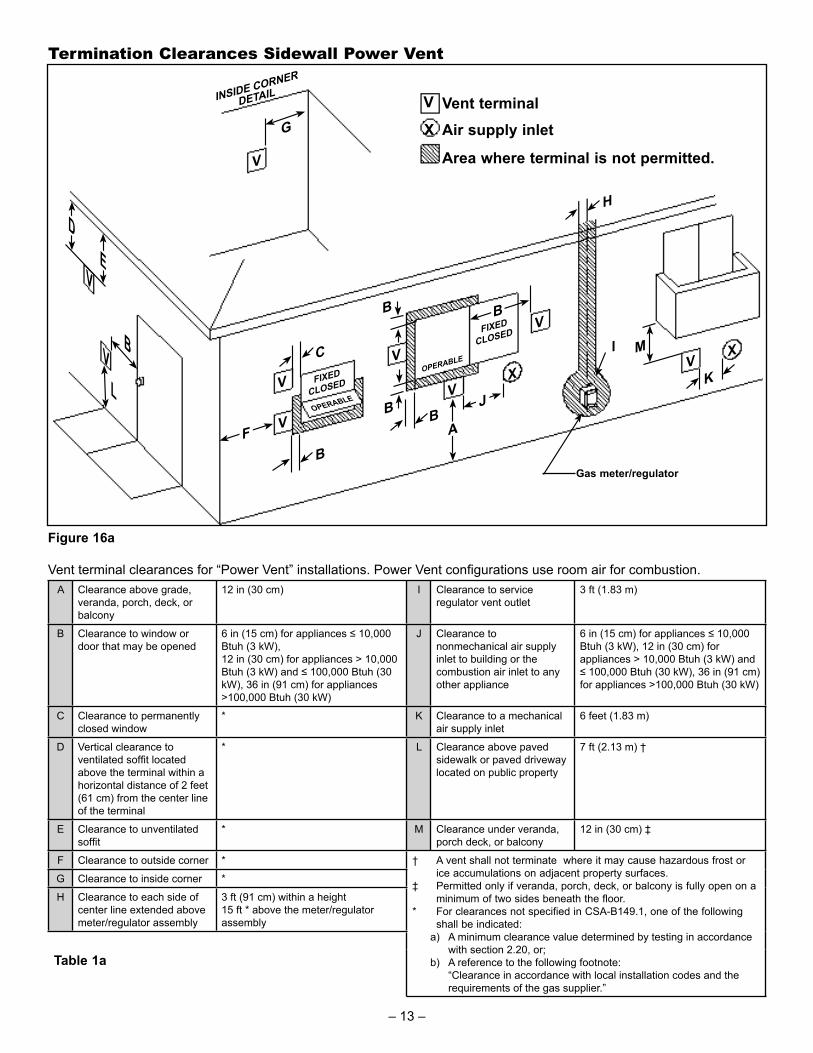
Termination Clearances Sidewall Power Vent
Vent terminalAir supply inlet
Area where terminal is not permitted.
Gas meter/regulator
V
X
B
C
V
V
V
B
B BA
VJ
BV
I MV
X
K
F
V
G
FIXED
CLOSED
FIXED
CLOSED
OPERABLE
OPERABLE
INSIDE CORNER
DETAIL
D
VE
VB
LX
H
Figure 16a
Vent terminal clearances for “Power Vent” installations. Power Vent confi gurations use room air for combustion.A Clearance above grade,
veranda, porch, deck, or balcony
12 in (30 cm) I Clearance to service regulator vent outlet
3 ft (1.83 m)
B Clearance to window or door that may be opened
6 in (15 cm) for appliances ≤ 10,000 Btuh (3 kW), 12 in (30 cm) for appliances > 10,000 Btuh (3 kW) and ≤ 100,000 Btuh (30 kW), 36 in (91 cm) for appliances >100,000 Btuh (30 kW)
J Clearance to nonmechanical air supply inlet to building or the combustion air inlet to any other appliance
6 in (15 cm) for appliances ≤ 10,000 Btuh (3 kW), 12 in (30 cm) for appliances > 10,000 Btuh (3 kW) and ≤ 100,000 Btuh (30 kW), 36 in (91 cm) for appliances >100,000 Btuh (30 kW)
C Clearance to permanently closed window
* K Clearance to a mechanical air supply inlet
6 feet (1.83 m)
D Vertical clearance to ventilated soffi t located above the terminal within a horizontal distance of 2 feet (61 cm) from the center line of the terminal
* L Clearance above paved sidewalk or paved driveway located on public property
7 ft (2.13 m) †
E Clearance to unventilated soffi t
* M Clearance under veranda, porch deck, or balcony
12 in (30 cm) ‡
F Clearance to outside corner * † A vent shall not terminate where it may cause hazardous frost or ice accumulations on adjacent property surfaces.
‡ Permitted only if veranda, porch, deck, or balcony is fully open on a minimum of two sides beneath the floor.
* For clearances not specified in CSA-B149.1, one of the following shall be indicated:
a) A minimum clearance value determined by testing in accordance with section 2.20, or;
b) A reference to the following footnote:“Clearance in accordance with local installation codes and the requirements of the gas supplier.”
G Clearance to inside corner *
H Clearance to each side of center line extended above meter/regulator assembly
3 ft (91 cm) within a height 15 ft * above the meter/regulator assembly
Table 1a
– 13 –
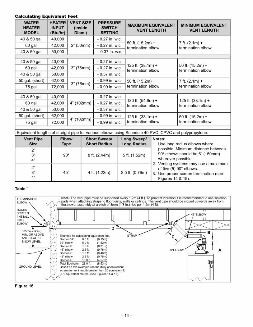
Calculating Equivalent FeetWATER HEATER MODEL
HEATER INPUT
(Btu/hr)
VENT SIZE(Inside Diam.)
PRESSURE SWITCH SETTING
MAXIMUM EQUIVALENT VENT LENGTH
MINIMUM EQUIVALENT VENT LENGTH
40 & 50 gal. 40,0002” (50mm)
- 0.27 in. w.c.50 ft. (15.2m) + termination elbow
7 ft. (2.1m) + termination elbow60 gal. 42,000 - 0.27 in. w.c.
40 & 50 gal. 50,000 - 0.37 in. w.c
40 & 50 gal. 40,0003” (76mm)
- 0.27 in. w.c.125 ft. (38.1m) + termination elbow
50 ft. (15.2m) + termination elbow60 gal. 42,000 - 0.27 in. w.c.
40 & 50 gal. 50,000 - 0.37 in. w.c.50 gal. (short) 62,000
3” (76mm)- 0.99 in. w.c. 50 ft. (15.2m) +
termination elbow7 ft. (2.1m) + termination elbow75 gal. 72,000 - 0.99 in. w.c.
40 & 50 gal. 40,0004” (102mm)
- 0.27 in. w.c.180 ft. (54.9m) + termination elbow
125 ft. (38.1m) + termination elbow60 gal. 42,000 - 0.27 in. w.c.
40 & 50 gal. 50,000 - 0.37 in. w.c.50 gal. (short) 62,000
4” (102mm)- 0.99 in. w.c. 125 ft. (38.1m) +
termination elbow50 ft. (15.2m) + termination elbow75 gal. 72,000 - 0.99 in. w.c.
Equivalent lengths of straight pipe for various elbows using Schedule 40 PVC, CPVC and polypropylene.Vent Pipe
SizeElbow Type
Short Sweep/Short Radius
Long Sweep/Long Radius
Notes: 1. Use long radius elbows where
possible. Minimum distance between 90º elbows should be 6” (150mm) wherever possible.
2. Venting systems may use a maximum of fi ve (5) 90° elbows.
3. Use proper screen termination (see Figures 14 & 15).
2”3"4"
90° 8 ft. (2.44m) 5 ft. (1.52m)
2”3"4"
45° 4 ft. (1.22m) 2.5 ft. (0.76m)
Table 1
Example for calculating equivalent feet.Section “A” 0.5 ft. (0.15m)90° elbow 5.0 ft. (1.52m)Section B 1.0 ft. (0.31m)45° elbow 2.5 ft. (0.76m)Section C 1.5 ft. (0.46m)45° elbow 2.5 ft. (0.76m)Section D 15.0 ft. (4.57m)Total Equivalent 28.0 ft. (8.53m)Based on this example use the (fully open) rodent screen for vent length greater than 20 equivalent ft. (6.1 equivalent metres) (see Figures 14 & 15).
Note: The vent pipe must be supported every 1.2m (4 ft.). To prevent vibration it is recommended to use isolation pads when attaching straps to fl oor joists, walls or ceilings. The vent pipe should be sloped upwards away from the blower assembly at a pitch of 3mm (1/8 in.) rise per 1.2m (4 ft).
STRAP
45°ELBOW
90°ELBOW
RODENT SCREEN (INSTALL INTO ELBOW)
TERMINATION ELBOW
GROUND LEVEL
305mm (12 in.) MIN. OR ABOVE ANTICIPATED SNOW LEVEL.
Figure 16
– 14 –

Venting Instructions1. Plan the venting layout starting at the vent termination
and work back toward the heater. Take into consider-ation the style and position of the vent termination, the vent pipe routing, elbows and connectors required and the necessary support hangers. Follow the vent manu-facturer's installation instructions.
2. 40, 50 and 60-gallon heaters may use 2 in., 3 in. or 4 in. venting depending on "Equivalent Vent Length" as described in Table 1. High input models require 3 in. or 4 in. venting. See also the section on "Vent pipe connec-tion to blower".
3. Venting should be as direct as possible with the fewest number of fittings. Use long radius 45 degree and long radius 90 degree elbows wherever possible.
4. Avoid the use of 90 degree elbows "back to back" and do not use street elbows. Maintain a minimum 150mm (6 in.) straight section between elbows. Closely coupled and short radius elbows reduce the venting capacity. Figure 13 shows examples of vent pipe connections.
5. DO NOT USE AN ELBOW AS A SUPPORT POINT. Elbows are not designed to carry the weight of the vent-ing system.
6. Calculate "Equivalent Vent Length" before starting. Do not exceed the values shown in Table 1. An example of how this length is determined is shown in Figure 16. The value from your calculations should also be used to determine which rodent screen to install into the vent termination elbow.
7. Follow the vent manufacturer's instructions for cutting and assembling the venting.
8. Provide support hangers for horizontal vent piping every 1.2m (4 ft.) to prevent sagging and stress. Provide a minimum of 3mm (1/8 in.) rise per 1.2m (4 ft.) of vent piping to ensure adequate drainage. Horizontal vent pip-ing must not sag to form valleys where condensate may collect. Vertical venting shall be supported every 1.5m (5 ft.).
CAUTION:Use of Solvent Cement and Primer• Use only in well-ventilated areas.• Do not use near fl ame or open fi re.• Use only the Solvent Cement and Primer
appropriate for the venting material being used.
• Solvent cements for plastic pipe are fl am-mable liquids and must be kept away from all sources of ignition.
SEALANT
SEALANTGROUND LEVEL*
RODENT SCREEN (INSTALL INTO ELBOW)
* WHERE SNOW COVER IS NORMAL DURING WINTER, ENSURE OUTLET IS INSTALLED ABOVE ANTICIPATED SNOW LEVEL.
305mm (12 in.) MIN.*
ATTACH TERMINATION ELBOW
152mm (6 in.)
THE END OF THE VENT PIPING MAY BE SLOPED IN ANY DIRECTION, AS LONG AS A WATER TRAP IS NOT CREATED IN THE VENTING SYSTEM. THE SLOPE SHOULD BE KEPT TO A MINIMUM SO AS NOT TO EXERT ANY UNDUE STRESS ON THE PIPE.
Figure 17
BRACKET
VENT RISER
SEALANT
SEALANT
ATTACH TERMINATION ELBOW
GROUND LEVEL*
RODENT SCREEN (INSTALL INTO ELBOW)
VENT PIPING TO BE SLOPED (DOWN) TOWARD HEATER TO PREVENT WATER FROM COLLECTING (MAY REQUIRE A CONDENSATE TEE).
EQUIVALENT VENT LENGTH MEASURED FROM THIS POSITION
* WHERE SNOW COVER IS NORMAL DURING WINTER, ENSURE OUTLET IS INSTALLED ABOVE ANTICIPATED SNOW LEVEL.
305mm (12 in.) MIN.*
Figure 18
Caution: Solvent cements may produce fl ammable vapours. Use only in well-ventilated areas and keep away from all sources of ignition.Note: Vapours produced by solvent cements can trigger the vapour sensor and lock-out the heater (see "Flammable Vapour Sensor" section).9. Install the properly sized rodent screen into the outlet
elbow and secure with a small quantity of silicone seal-ant (see "Rodent Screen" section).
10. Do not seal the vent piping to the wall until the venting is properly connected to the blower assembly.
– 15 –
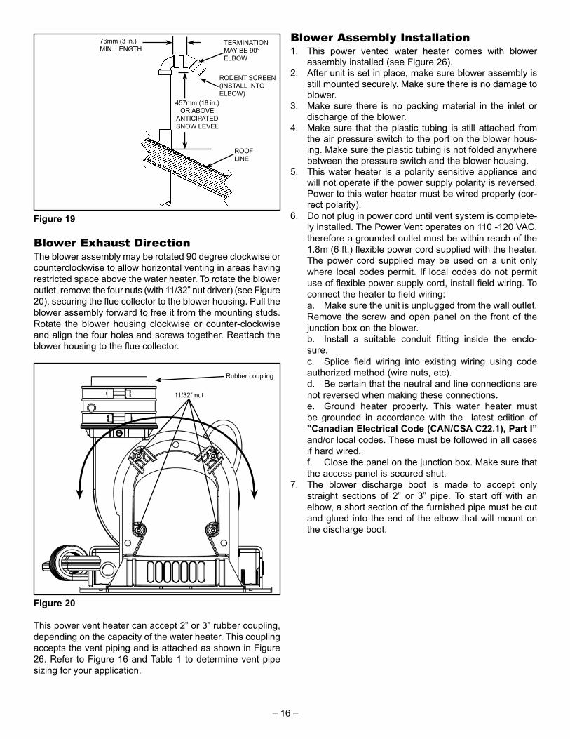
TERMINATION MAY BE 90° ELBOW
76mm (3 in.) MIN. LENGTH
ROOF LINE
457mm (18 in.) OR ABOVE
ANTICIPATED SNOW LEVEL
RODENT SCREEN (INSTALL INTO ELBOW)
Figure 19
Blower Exhaust DirectionThe blower assembly may be rotated 90 degree clockwise or counterclockwise to allow horizontal venting in areas having restricted space above the water heater. To rotate the blower outlet, remove the four nuts (with 11/32” nut driver) (see Figure 20), securing the fl ue collector to the blower housing. Pull the blower assembly forward to free it from the mounting studs. Rotate the blower housing clockwise or counter-clockwise and align the four holes and screws together. Reattach the blower housing to the fl ue collector.
11/32” nut
Rubber coupling
Figure 20
This power vent heater can accept 2” or 3” rubber coupling, depending on the capacity of the water heater. This coupling accepts the vent piping and is attached as shown in Figure 26. Refer to Figure 16 and Table 1 to determine vent pipe sizing for your application.
Blower Assembly Installation1. This power vented water heater comes with blower
assembly installed (see Figure 26).2. After unit is set in place, make sure blower assembly is
still mounted securely. Make sure there is no damage to blower.
3. Make sure there is no packing material in the inlet or discharge of the blower.
4. Make sure that the plastic tubing is still attached from the air pressure switch to the port on the blower hous-ing. Make sure the plastic tubing is not folded anywhere between the pressure switch and the blower housing.
5. This water heater is a polarity sensitive appliance and will not operate if the power supply polarity is reversed. Power to this water heater must be wired properly (cor-rect polarity).
6. Do not plug in power cord until vent system is complete-ly installed. The Power Vent operates on 110 -120 VAC. therefore a grounded outlet must be within reach of the 1.8m (6 ft.) flexible power cord supplied with the heater. The power cord supplied may be used on a unit only where local codes permit. If local codes do not permit use of flexible power supply cord, install field wiring. To connect the heater to field wiring:
a. Make sure the unit is unplugged from the wall outlet. Remove the screw and open panel on the front of the junction box on the blower.
b. Install a suitable conduit fitting inside the enclo-sure.
c. Splice field wiring into existing wiring using code authorized method (wire nuts, etc).
d. Be certain that the neutral and line connections are not reversed when making these connections.
e. Ground heater properly. This water heater must be grounded in accordance with the latest edition of "Canadian Electrical Code (CAN/CSA C22.1), Part I” and/or local codes. These must be followed in all cases if hard wired.
f. Close the panel on the junction box. Make sure that the access panel is secured shut.
7. The blower discharge boot is made to accept only straight sections of 2” or 3” pipe. To start off with an elbow, a short section of the furnished pipe must be cut and glued into the end of the elbow that will mount on the discharge boot.
– 16 –

Vent Pipe Connection to BlowerCAUTION:
• Do Not Overtighten The Top And Bottom Gear Clamps Of The Rubber Coupling.
• Do Not Apply Solvent Cement Or Silicone To The Rubber Coupling Connection.
1. The plastic vent piping connects into the rubber coupling located on the top of the blower assembly. This cou-pling includes gear clamps to connect the venting to the blower. These connections must be properly seated and tightened to prevent the leakage of flue gases into the area. See Figures 21-25.
2. The 40, 50 and 60-gallon heaters with rated inputs of 50,000 Btu/hr or less are designed and supplied with a 51mm (2 in.) rubber coupling to accept the vent pipe.
3. The 50 and 75-gallon models with rated inputs of 60,000 Btu/hr or more are supplied with a 76mm (3 in.) rubber coupling to accept the vent pipe.
4. Before installing clean and lightly sand the end of the plastic vent piping that will connect into the rubber cou-pling.
5. Loosen the upper clamp on the rubber coupling and insert the sanded end of the vent piping a full 32mm (1-1/4 in.). Do not use glue or sealant in the rubber coupling. Check that there is no stress on the connection or the vent piping that may be caused by twisting or bending.
6. Tighten the upper clamp so that the vent piping is firmly secured in the coupling and is gas tight. Do not over tighten or cause distortion of any of the parts. Ensure the bottom of the rubber coupling is firmly seated on the blower outlet and that the lower gear clamp is also secure. Check to ensure there is no distortion or move-ment of the clamped assembly once it is completed.
BLOWER
2” VENT PIPE
2” RUBBER COUPLING (SUPPLIED)
CONFIGURATION FOR 40, 50 AND 60-GALLON (LO-INPUT) HEATERS CONNECTED TO 2" VENTING.
Figure 21
2” RUBBER COUPLING (SUPPLIED)
BLOWER
3” VENT PIPE
2”-3” ADAPTER*
(FIELD SUPPLIED)
2” VENT PIPE, 75mm (3 in.)
MAX LENGTH
CONFIGURATION FOR 40, 50 AND 60-GALLON (LO-INPUT) HEATERS CONNECTED TO 3” VENTING.
* FOR 3” DIRECT CONNECTION TO THE BLOWER, ORDER COUPLING Kit # 9008311005 (SEE ALSO FIGURE 24).
Figure 22
4” VENT PIPE3” RUBBER
COUPLING(ORDER COUPLING
Kit # 9008311005 TO REPLACE 2”
RUBBER COUPLING SUPPLIED.) 3” VENT PIPE,
75mm (3 in.) MAX LENGTH
3”-4” ADAPTER
(FIELD SUPPLIED)
BLOWER
CONFIGURATION FOR LO-INPUT HEATERS CONNECTED TO 4” VENTING.
LOW-INPUT HEATERS ARE SUPPLIED WITH A 2” RUBBER COUPLING.
Figure 23
3” VENT PIPE
3” RUBBER COUPLING (SUPPLIED)
BLOWER
CONFIGURATION FOR HI-INPUT HEATERS CONNECTED TO 3” VENTING.
(OPTIONAL CONFIGURATION FOR LO-INPUT HEATERS CONNECTED TO 3” VENTING.)
Figure 24
4” VENT PIPE
3” RUBBER COUPLING (SUPPLIED) 3” VENT PIPE,
75mm (3 in.) MAX LENGTH
3”-4” ADAPTER
(FIELD SUPPLIED)
BLOWER
CONFIGURATION FOR HI-INPUT HEATER CONNECTED TO 4” VENTING.
Figure 25
– 17 –

CondensateCondensate formation does not occur in all installations of power vented water heaters, but should be drained on installations where it can form in the venting system. Condensation in the venting system of power vented water heaters is dependent upon installation conditions including, but not limited to ambient temperature and humidity of installation location, ambient temperature and humidity of venting space, vent discharge and slope, and product usage. In certain conditions, installations in unconditioned space or having long horizontal or vertical vent runs can accumulate condensate. Long lengths of venting that pass through cool/cold areas will experience condensation. The vent pipe should be sloped upwards away from the blower assembly, then adequate means for draining and disposing of the condensate needs to be made by the installer. If installation conditions cause condensation, install a condensate trap loop approximately 200mm (8 in.) in diameter using 3/8" plastic hose. Connect the hose to the built-in drain port of the rubber coupling of the blower assembly (see Figure 26). Loop the hose in a vertical position as shown. The tube loop must be fi lled with water at least half way prior to operating the heater. Ensure the end of the tube has access to a drain as condensate will fl ow from the end. Secure the tubing to the side of the heater. Prior to operating the water heater, make sure the removable cap is installed on the drain port (if a drain hose is not needed). Note: This cap must remain in place if a drain hose is not installed.
HOSE CONNECTION
PORT FOR CONDENSATE
DRAIN
DILUTION AIR
INLETS
200mm (8 in.) LOOP
TO DRAIN
BLOWER ASSEMBLY
Figure 26
Water Supply Piping InstallationPiping, fi ttings, and valves should be installed according to the installation drawing (Figure 27). Water supply pressure should not exceed 550 kPa (80psi). If this occurs a pressure reducing valve and/or an expansion tank may be required. The pressure reducing valve should be placed on the supply to the entire house in order to maintain equal hot and cold water pressures.
Important:• Do not apply heat to the water fittings on the heater as
they may contain nonmetallic parts. If solder connections are used, solder the pipe to an adapter before attaching the adapter to the hot and cold water fittings.
• All models contain energy saving heat traps to prevent the circulation of hot water within the pipes.
• Always use a proper grade of joint compound and be certain that all fittings are drawn up tight.
1. Install the water piping and fittings as shown in Figure 27. Connect the cold water supply to the fitting (3/4" NPT) marked "COLD" (or "C"). Connect the hot water supply to the fitting (3/4" NPT) marked "HOT" (or "H").
2. The installation of unions in both the hot and cold water supply lines is recommended.
3. The manufacturer of this water heater recommends installing a tempering valve in the domestic hot-water line as shown in Figure 28. These valves reduce the point-of-use water temperature by mixing cold and hot water.
4. If installing the water heater in a closed water system, install an expansion tank in the cold water line as speci-fied under "Closed System/Thermal Expansion".
5. Install a shut-off valve in the cold-water inlet line. It should be located close to the water heater and be easily accessible. The owner/operator must be shown the loca-tion of this valve and be given instructions on how to use it to shut off the water to the heater.
– 18 –

Filling the Water HeaterDo not insert the power cord into the electrical receptacle until all the following steps have been completed.1. Make sure the drain valve is closed.2. Open a nearby hot-water faucet served by the system to
allow air to escape from the tank.3. Open the cold-water inlet valve.
Note: When filling, avoid water leakage. Do not allow the insulation of the water heater to get wet as water can reduce the effectiveness of the insulation.
4. When an uninterrupted stream of water, without apparent air bubbles, flows from the open hot-water faucets, the tank is full.
5. Close the hot-water faucets and check the system for leaks. Repair as required and retest.
Please note the following:The system should be installed only with piping that is suitable for potable (drinkable) water.DO NOT use any pumps, valves, or fi ttings that are not compatible with potable water.AVOID use of valves that may cause excessive restriction to water fl ow. Use full fl ow ball or gate valves only.DO NOT use any lead based solder in potable water lines. Use appropriate tin-antimony or other equivalent material.DO NOT tamper with the gas control/thermostat, igniter, fl ammable vapour sensor or temperature and pressure relief valve. Tampering voids all warranties. Only a qualifi ed service technician should service these components.DO NOT use with piping that has been treated with chromates, boiler seal, or other chemicals.DO NOT add any chemicals to the system piping which will contaminate the potable water supply.
COLD WATER INLET
COLD WATER INLET VALVE
TEMPERATURE AND PRESSURE RELIEF VALVE
HOTWATER OUTLET
UNION
DRAIN PAN CONNECT TO PROPERLY OPERATING FLOOR DRAIN.
DISCHARGE LINE 300mm (12 in.) max ABOVE FLOOR
In a closed system use either:1.THERMAL EXPANSION TANK2.PRESSURE RELIEF VALVE.
NOTE: BLOWER ASSEMBLY NOT SHOWN FOR CLARITY.
1
2
Figure 27
COLD WATER INLET
HOT WATER OUTLET
TEMPERING VALVE (SET TO 49°C (120°F))
FOLLOW THE TEMPERING VALVE MANUFACTURER'S INSTRUCTIONS
T&P VALVE AND DISCHARGE LINE
COLD WATER
TEMPERED
WATER TO
FIXTURE
Figure 28
Closed System/Thermal ExpansionWater supply systems may, because of code requirements or such conditions as high line pressure, among others, have installed devices such as pressure reducing valves, check valves, and back fl ow preventers. Devices such as these cause the water system to be a closed system. As water is heated, it expands (thermal expansion). In a closed system the volume of water will grow when it is heated. As the volume of water grows there will be a corresponding increase in water pressure due to thermal expansion. Thermal expansion can cause premature tank failure (leakage). This type of failure is not covered under the limited warranty. Thermal expansion can also cause intermittent Temperature-Pressure Relief Valve operation: water discharged from the valve due to excessive pressure buildup. This condition is not covered under the limited warranty. The Temperature-Pressure Relief Valve is not intended for the constant relief of thermal expansion. A properly sized thermal expansion tank must be installed on all closed systems to control the harmful effects of thermal expansion. Contact a local plumbing service agency to have a thermal expansion tank installed. Important: Do not plug or remove the temperature and pressure (T&P) relief valve.
Temperature and Pressure (T&P) Relief ValveFor protection against excessive pressures and temperatures, a temperature and pressure relief valve must be installed in the opening marked "T&P RELIEF VALVE" (see Figure 30). This valve must be design certifi ed to meet the requirements of the "Standard For Relief Valves For Hot Water Supply Systems", ANSI Z21.22/CSA 4.4. The function of the temperature and pressure relief valve is to discharge water in large quantities in the event of excessive temperature or pressure developing in the water heater. The valve's relief pressure must not exceed the working pressure of the water heater as stated on the data plate.
– 19 –
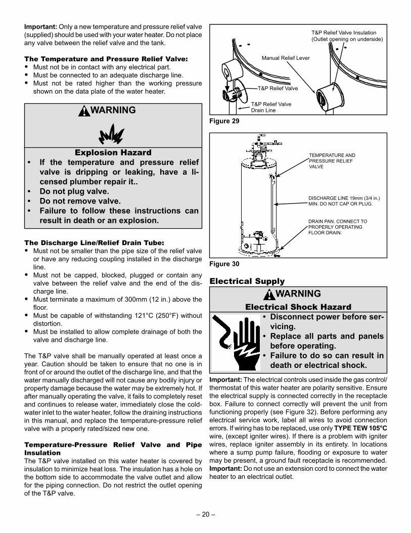
Important: Only a new temperature and pressure relief valve (supplied) should be used with your water heater. Do not place any valve between the relief valve and the tank.
The Temperature and Pressure Relief Valve:• Must not be in contact with any electrical part.• Must be connected to an adequate discharge line.• Must not be rated higher than the working pressure
shown on the data plate of the water heater.
WARNING
Explosion Hazard• If the temperature and pressure relief
valve is dripping or leaking, have a li-censed plumber repair it..
• Do not plug valve.• Do not remove valve.• Failure to follow these instructions can
result in death or an explosion.
The Discharge Line/Relief Drain Tube:• Must not be smaller than the pipe size of the relief valve
or have any reducing coupling installed in the discharge line.
• Must not be capped, blocked, plugged or contain any valve between the relief valve and the end of the dis-charge line.
• Must terminate a maximum of 300mm (12 in.) above the floor.
• Must be capable of withstanding 121°C (250°F) without distortion.
• Must be installed to allow complete drainage of both the valve and discharge line.
The T&P valve shall be manually operated at least once a year. Caution should be taken to ensure that no one is in front of or around the outlet of the discharge line, and that the water manually discharged will not cause any bodily injury or property damage because the water may be extremely hot. If after manually operating the valve, it fails to completely reset and continues to release water, immediately close the cold-water inlet to the water heater, follow the draining instructions in this manual, and replace the temperature-pressure relief valve with a properly rated/sized new one.
Temperature-Pressure Relief Valve and Pipe InsulationThe T&P valve installed on this water heater is covered by insulation to minimize heat loss. The insulation has a hole on the bottom side to accommodate the valve outlet and allow for the piping connection. Do not restrict the outlet opening of the T&P valve.
T&P Relief Valve
T&P Relief ValveDrain Line
Manual Relief Lever
T&P Relief Valve Insulation(Outlet opening on underside)
Figure 29
TEMPERATURE AND PRESSURE RELIEF VALVE
DISCHARGE LINE 19mm (3/4 in.) MIN. DO NOT CAP OR PLUG.
DRAIN PAN. CONNECT TO PROPERLY OPERATING FLOOR DRAIN.
Figure 30
Electrical SupplyWARNING
Electrical Shock Hazard• Disconnect power before ser-
vicing.• Replace all parts and panels
before operating.• Failure to do so can result in
death or electrical shock.Important: The electrical controls used inside the gas control/thermostat of this water heater are polarity sensitive. Ensure the electrical supply is connected correctly in the receptacle box. Failure to connect correctly will prevent the unit from functioning properly (see Figure 32). Before performing any electrical service work, label all wires to avoid connection errors. If wiring has to be replaced, use only TYPE TEW 105°C wire, (except igniter wires). If there is a problem with igniter wires, replace igniter assembly in its entirety. In locations where a sump pump failure, fl ooding or exposure to water may be present, a ground fault receptacle is recommended.Important: Do not use an extension cord to connect the water heater to an electrical outlet.
– 20 –
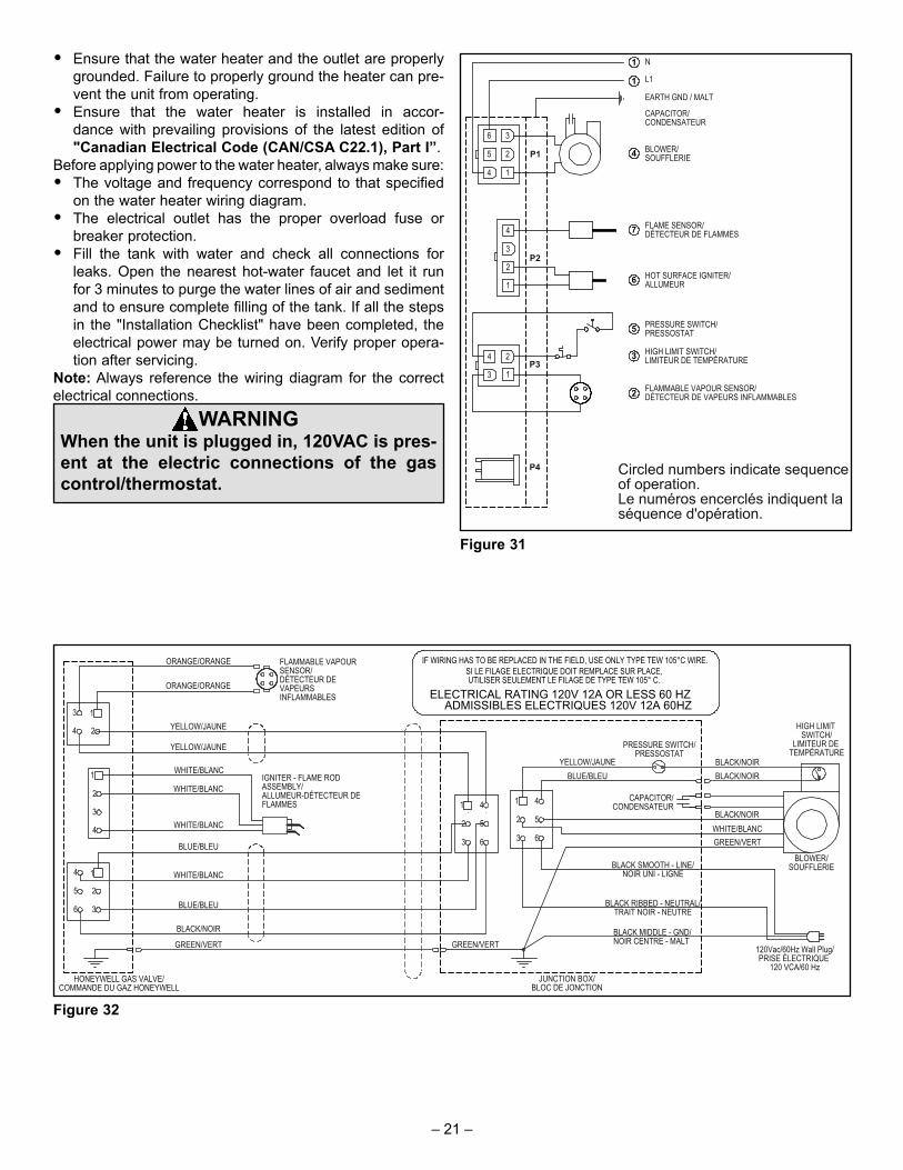
• Ensure that the water heater and the outlet are properly grounded. Failure to properly ground the heater can pre-vent the unit from operating.
• Ensure that the water heater is installed in accor-dance with prevailing provisions of the latest edition of "Canadian Electrical Code (CAN/CSA C22.1), Part I”.
Before applying power to the water heater, always make sure:• The voltage and frequency correspond to that specified
on the water heater wiring diagram.• The electrical outlet has the proper overload fuse or
breaker protection.• Fill the tank with water and check all connections for
leaks. Open the nearest hot-water faucet and let it run for 3 minutes to purge the water lines of air and sediment and to ensure complete filling of the tank. If all the steps in the "Installation Checklist" have been completed, the electrical power may be turned on. Verify proper opera-tion after servicing.
Note: Always reference the wiring diagram for the correct electrical connections.
WARNINGWhen the unit is plugged in, 120VAC is pres-ent at the electric connections of the gas control/thermostat.
Figure 31
Figure 32
– 21 –
SAFETY LOCKOUTSThis water heater has several lockout features designed to prevent the heater from operating in unsafe conditions.
High Limit Controls Thermostat/Water TemperatureThis feature is a part of the gas control valve/thermostat (see Figure 35) and limits the maximum water temperature. In the event of the water overheating, this safety feature shuts off the fuel supply to the burner.
Blower Exhaust Gas Limit SwitchThis device is located on the blower (see Item 5, Figure 9) and limits the maximum temperature of the blower. If the blower temperature rises above the temperature setting, the switch opens causing the heater to shut down. The switch will auto reset once the temperature drops suffi ciently.
Blower Air Pressure SwitchThis device, located in the junction box, monitors the air pressure produced by the blower. In the event that the exhaust venting becomes blocked or suffi ciently restricted, the switch will shut the heater down (see Item 22, Figure 9).
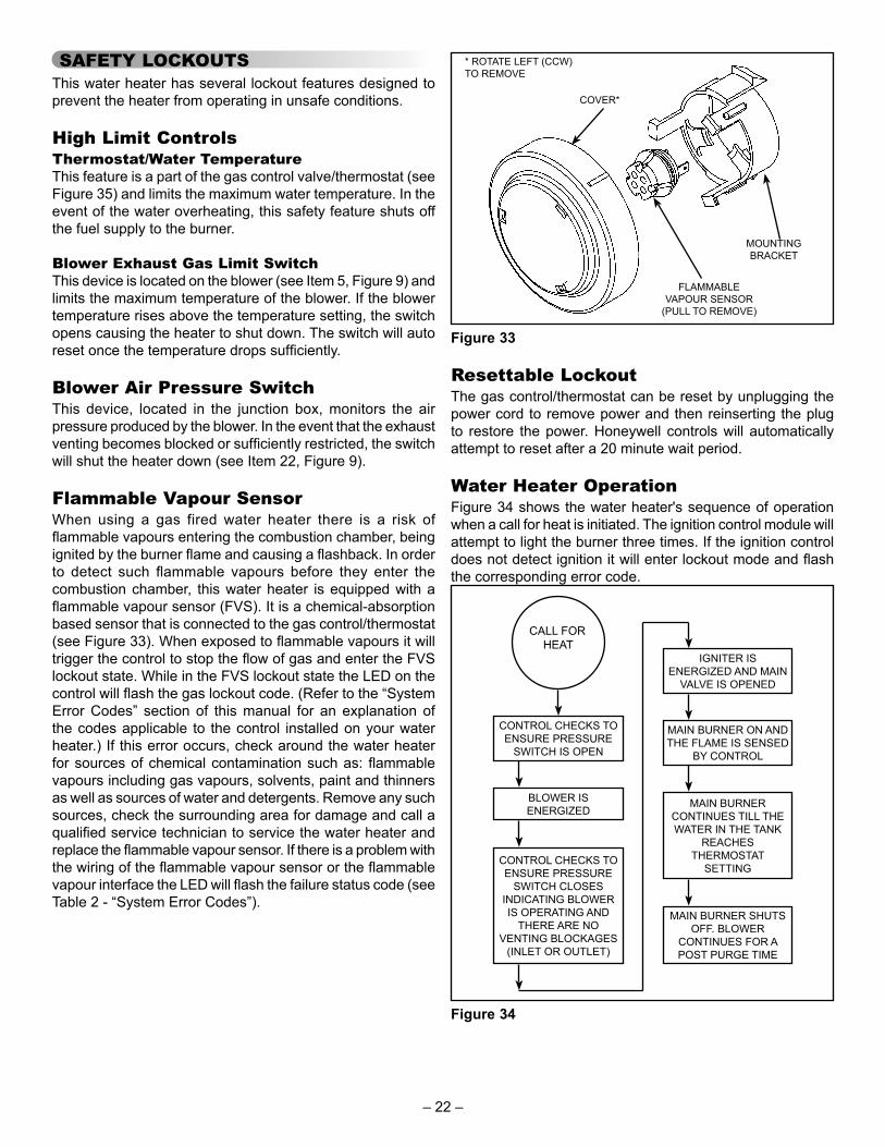
Flammable Vapour SensorWhen using a gas fired water heater there is a risk of fl ammable vapours entering the combustion chamber, being ignited by the burner fl ame and causing a fl ashback. In order to detect such fl ammable vapours before they enter the combustion chamber, this water heater is equipped with a fl ammable vapour sensor (FVS). It is a chemical-absorption based sensor that is connected to the gas control/thermostat (see Figure 33). When exposed to fl ammable vapours it will trigger the control to stop the fl ow of gas and enter the FVS lockout state. While in the FVS lockout state the LED on the control will fl ash the gas lockout code. (Refer to the “System Error Codes” section of this manual for an explanation of the codes applicable to the control installed on your water heater.) If this error occurs, check around the water heater for sources of chemical contamination such as: fl ammable vapours including gas vapours, solvents, paint and thinners as well as sources of water and detergents. Remove any such sources, check the surrounding area for damage and call a qualifi ed service technician to service the water heater and replace the fl ammable vapour sensor. If there is a problem with the wiring of the fl ammable vapour sensor or the fl ammable vapour interface the LED will fl ash the failure status code (see Table 2 - “System Error Codes”).
MOUNTING BRACKET
FLAMMABLE VAPOUR SENSOR
(PULL TO REMOVE)
COVER*
* ROTATE LEFT (CCW) TO REMOVE
Figure 33
Resettable LockoutThe gas control/thermostat can be reset by unplugging the power cord to remove power and then reinserting the plug to restore the power. Honeywell controls will automatically attempt to reset after a 20 minute wait period.
Water Heater OperationFigure 34 shows the water heater's sequence of operation when a call for heat is initiated. The ignition control module will attempt to light the burner three times. If the ignition control does not detect ignition it will enter lockout mode and fl ash the corresponding error code.
CONTROL CHECKS TO ENSURE PRESSURE
SWITCH IS OPEN
BLOWER ISENERGIZED
CONTROL CHECKS TO ENSURE PRESSURE
SWITCH CLOSESINDICATING BLOWER IS OPERATING AND
THERE ARE NOVENTING BLOCKAGES
(INLET OR OUTLET)
IGNITER ISENERGIZED AND MAIN
VALVE IS OPENED
MAIN BURNER ON AND THE FLAME IS SENSED
BY CONTROL
MAIN BURNERCONTINUES TILL THE WATER IN THE TANK
REACHESTHERMOSTAT
SETTING
MAIN BURNER SHUTS OFF. BLOWER
CONTINUES FOR A POST PURGE TIME
CALL FOR HEAT
Figure 34
– 22 –
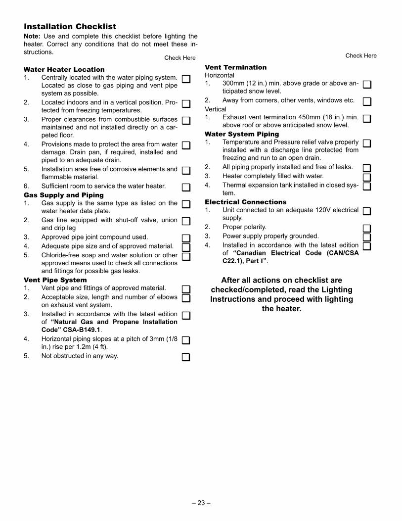
Installation ChecklistNote: Use and complete this checklist before lighting the heater. Correct any conditions that do not meet these in-structions.
Water Heater Location1. Centrally located with the water piping system.
Located as close to gas piping and vent pipe system as possible.
2. Located indoors and in a vertical position. Pro-tected from freezing temperatures.
3. Proper clearances from combustible surfaces maintained and not installed directly on a car-peted floor.
4. Provisions made to protect the area from water damage. Drain pan, if required, installed and piped to an adequate drain.
5. Installation area free of corrosive elements and flammable material.
6. Sufficient room to service the water heater.Gas Supply and Piping1. Gas supply is the same type as listed on the
water heater data plate.2. Gas line equipped with shut-off valve, union
and drip leg3. Approved pipe joint compound used.4. Adequate pipe size and of approved material.5. Chloride-free soap and water solution or other
approved means used to check all connections and fittings for possible gas leaks.
Vent Pipe System1. Vent pipe and fittings of approved material.2. Acceptable size, length and number of elbows
on exhaust vent system.3. Installed in accordance with the latest edition
of “Natural Gas and Propane Installation Code” CSA-B149.1.
4. Horizontal piping slopes at a pitch of 3mm (1/8 in.) rise per 1.2m (4 ft).
5. Not obstructed in any way.
Check HereVent TerminationHorizontal1. 300mm (12 in.) min. above grade or above an-
ticipated snow level.2. Away from corners, other vents, windows etc.Vertical1. Exhaust vent termination 450mm (18 in.) min.
above roof or above anticipated snow level.Water System Piping1. Temperature and Pressure relief valve properly
installed with a discharge line protected from freezing and run to an open drain.
2. All piping properly installed and free of leaks.3. Heater completely filled with water.4. Thermal expansion tank installed in closed sys-
tem.Electrical Connections1. Unit connected to an adequate 120V electrical
supply.2. Proper polarity.3. Power supply properly grounded.4. Installed in accordance with the latest edition
of “Canadian Electrical Code (CAN/CSA C22.1), Part I”.
After all actions on checklist are checked/completed, read the Lighting Instructions and proceed with lighting
the heater.
Check Here
– 23 –
OPERATING INSTRUCTIONSCAUTION:
Read before proceeding. If you do notfollow these instructions exactly, a fi re or explosion may result, causing property damage, personal injury or loss of life.
This appliance is equipped with an ignition device that automatically lights the burner.
Do not try to light manually witha match or fl ame.
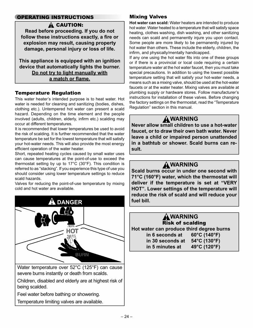
Temperature RegulationThis water heater’s intended purpose is to heat water. Hot water is needed for cleaning and sanitizing (bodies, dishes, clothing etc.). Untempered hot water can present a scald hazard. Depending on the time element and the people involved (adults, children, elderly, infi rm etc.) scalding may occur at different temperatures.It is recommended that lower temperatures be used to avoid the risk of scalding. It is further recommended that the water temperature be set for the lowest temperature that will satisfy your hot-water needs. This will also provide the most energy effi cient operation of the water heater.Short, repeated heating cycles caused by small water uses can cause temperatures at the point-of-use to exceed the thermostat setting by up to 17°C (30°F). This condition is referred to as “stacking”. If you experience this type of use you should consider using lower temperature settings to reduce scald hazards.Valves for reducing the point-of-use temperature by mixing cold and hot water are available.
DANGER
Water temperature over 52°C (125°F) can cause severe burns instantly or death from scalds.Children, disabled and elderly are at highest risk of being scalded.Feel water before bathing or showering.Temperature limiting valves are available.
Mixing ValvesHot water can scald: Water heaters are intended to produce hot water. Water heated to a temperature that will satisfy space heating, clothes washing, dish washing, and other sanitizing needs can scald and permanently injure you upon contact. Some people are more likely to be permanently injured by hot water than others. These include the elderly, children, the infi rm, and physically/mentally handicapped.If any one using the hot water fi ts into one of these groups or if there is a provincial or local code requiring a certain temperature water at the hot water faucet, then you must take special precautions. In addition to using the lowest possible temperature setting that will satisfy your hot-water needs, a means such as a mixing valve, should be used at the hot-water faucets or at the water heater. Mixing valves are available at plumbing supply or hardware stores. Follow manufacturer’s instructions for installation of these valves. Before changing the factory settings on the thermostat, read the “Temperature Regulation” section in this manual.
WARNINGNever allow small children to use a hot-water faucet, or to draw their own bath water. Never leave a child or impaired person unattended in a bathtub or shower. Scald burns can re-sult.
WARNINGScald burns occur in under one second with 71°C (160°F) water, which the thermostat will deliver if the temperature is set at “VERY HOT”. Lower settings of the temperature will reduce the risk of scald and will reduce your fuel bill.
WARNINGRisk of scalding
Hot water can produce third degree burns in 6 seconds at 60°C (140°F) in 30 seconds at 54°C (130°F) in 5 minutes at 49°C (120°F)
– 24 –

Lighting InstructionsRead and understand these directions thoroughly before attempting to operate the water heater. Make sure the viewport is not missing or damaged. Make sure the tank is completely fi lled with water before operating the water heater. The gas control valve/thermostat has an “On/Off Switch” and must be turned on before the water heater is operational. Check the label on the front of the water heater near the gas control valve/thermostat for the correct gas. Do not start this water heater with any gas other than the one listed on the label. If you have any questions or doubts, consult the gas supplier or gas utility company. The following Lighting Instruction label appears on the front of the water heater.
324501-000
1. Turn the thermostat counter-clockwise to the lowest setting.2. Set the gas control switch to the “OFF” position.3. Turn off electrical power to the appliance if service is to be performed.
TO TURN OFF GAS TO APPLIANCE
1. STOP! Read the safety information above on this label.
2. Turn off all electric power to the appliance.
3. Turn the thermostat counter-clockwise to the lowest setting.
4. Set the switch on the control to the “OFF” position.
5. Do not attempt to light manually.6. Wait five (5) minutes to clear out
any gas. If you then smell gas, STOP! Follow “B” in the safety information above on this label. If you don't smell gas, go the next step.
7. Turn on all electric power to the appliance.
8. Set the switch on the control to the “ON” position.
9. Turn thermostat to desired setting.DANGER Hotter water increases the risk of scald injury. Consult the instruction manual before changing temperature.
10. If the appliance will not operate, follow the instructions “To Turn Off Gas To Appliance” and call your service technician or gas supplier.
OPERATING INSTRUCTIONS
DANGER
A. This appliance does not have a pilot. It is equipped with an ignition device which automatically lights the burner. Do NOT try to light the burner by hand.
B. BEFORE OPERATING smell all around the appliance area for gas. Be sure to smell next to the floor because some gas is heavier than air and will settle on the floor.
WHAT TO DO IF YOU SMELL GAS: • Do not try to light any appliance. • Do not touch any electric switch; Do not use
any phone in your building. • Immediately call your gas supplier from a
neighbor's phone. Follow the gas suppliers instructions.
• If you cannot reach your gas supplier, call the fire department.
C. Use only your hand to turn the gas control buttons. Never use tools. If the control buttons will not turn, don't try to repair them, call a qualified service technician. Force or attempted repair may result in a fire or explosion.
D. Do not use this appliance if any part has been under water. Immediately contact a qualified installer or service agency to replace a flooded water heater. Do not attempt to repair the unit. It must be replaced!
BEFORE OPERATING: ENTIRE SYSTEM MUST BE FILLED WITH WATER AND AIR PURGED FROM ALL LINES.FLAMMABLE
WARNING: If you do not follow these instructions exactly, a fire or explosion may result causing property damage, personal injury or loss of life.
FOR YOUR SAFETY READ BEFORE LIGHTING
– 25 –
Operating The Temperature Control SystemIt is recommended that lower water temperatures be used to avoid the risk of scalding. It is further recommended, in all cases, that the water temperature be set for the lowest temperature which satisfi es your hot-water needs. This will also provide the most energy effi cient operation of the water heater.Short repeated heating cycles caused by small hot-water uses can cause a temperature increase of the hot water by 11C° (20F°) higher than the heater’s temperature settings. If you experience this type of use you should consider using lower temperature settings to reduce scald hazards.
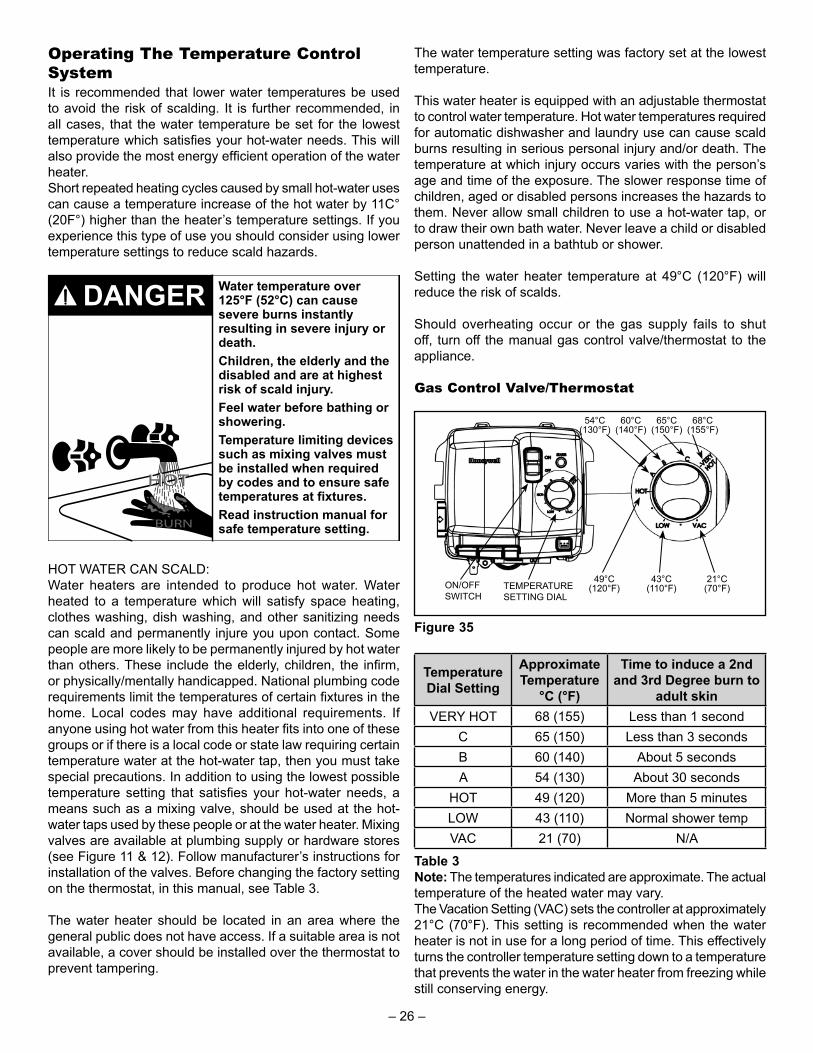
Water temperature over 125°F (52°C) can cause severe burns instantly resulting in severe injury or death.Children, the elderly and the disabled and are at highest risk of scald injury.Feel water before bathing or showering.Temperature limiting devices such as mixing valves must be installed when required by codes and to ensure safe temperatures at fixtures.Read instruction manual for safe temperature setting.BURN
HOTHOT
DANGER
HOT WATER CAN SCALD:Water heaters are intended to produce hot water. Water heated to a temperature which will satisfy space heating, clothes washing, dish washing, and other sanitizing needs can scald and permanently injure you upon contact. Some people are more likely to be permanently injured by hot water than others. These include the elderly, children, the infi rm, or physically/mentally handicapped. National plumbing code requirements limit the temperatures of certain fi xtures in the home. Local codes may have additional requirements. If anyone using hot water from this heater fi ts into one of these groups or if there is a local code or state law requiring certain temperature water at the hot-water tap, then you must take special precautions. In addition to using the lowest possible temperature setting that satisfi es your hot-water needs, a means such as a mixing valve, should be used at the hot-water taps used by these people or at the water heater. Mixing valves are available at plumbing supply or hardware stores (see Figure 11 & 12). Follow manufacturer’s instructions for installation of the valves. Before changing the factory setting on the thermostat, in this manual, see Table 3.
The water heater should be located in an area where the general public does not have access. If a suitable area is not available, a cover should be installed over the thermostat to prevent tampering.
The water temperature setting was factory set at the lowest temperature.
This water heater is equipped with an adjustable thermostat to control water temperature. Hot water temperatures required for automatic dishwasher and laundry use can cause scald burns resulting in serious personal injury and/or death. The temperature at which injury occurs varies with the person’s age and time of the exposure. The slower response time of children, aged or disabled persons increases the hazards to them. Never allow small children to use a hot-water tap, or to draw their own bath water. Never leave a child or disabled person unattended in a bathtub or shower.
Setting the water heater temperature at 49°C (120°F) will reduce the risk of scalds.
Should overheating occur or the gas supply fails to shut off, turn off the manual gas control valve/thermostat to the appliance.
Gas Control Valve/Thermostat
ON/OFF SWITCH
TEMPERATURE SETTING DIAL
68°C (155°F)
21°C (70°F)
54°C (130°F)
60°C (140°F)
65°C (150°F)
49°C (120°F)
43°C (110°F)
Figure 35
Temperature Dial Setting
Approximate Temperature
°C (°F)
Time to induce a 2nd and 3rd Degree burn to
adult skinVERY HOT 68 (155) Less than 1 second
C 65 (150) Less than 3 secondsB 60 (140) About 5 secondsA 54 (130) About 30 seconds
HOT 49 (120) More than 5 minutesLOW 43 (110) Normal shower tempVAC 21 (70) N/A
Table 3Note: The temperatures indicated are approximate. The actual temperature of the heated water may vary.The Vacation Setting (VAC) sets the controller at approximately 21°C (70°F). This setting is recommended when the water heater is not in use for a long period of time. This effectively turns the controller temperature setting down to a temperature that prevents the water in the water heater from freezing while still conserving energy.
– 26 –

OPERATION Burner FlamesInspect the burner fl ames through the viewport and compare them to the drawings in Figure 36. A properly operating burner should produce a soft blue fl ame. Blue tips with light blue inner cones are satisfactory. The tips of the fl ame may have a slight yellow tint. The fl ame should not be all yellow or have a sharp blue-orange colour. Contaminated air may cause an orange coloured fl ame. Contact a qualifi ed service technician if the fl ame is not satisfactory.
CORRECT FLAME SOFT BLUE
INCORRECT FLAME LAZY
YELLOW
BLUE TIPS (NAT. GAS), BLUE FLAME WITH
YELLOW TIPS (LP GAS)
LIGHT BLUE INNER CONES ARE
SATISFACTORY
Figure 36
Operational Conditions CondensationMoisture from the products of combustion condenses on the tank surface and forms drops of water that may fall onto the burner or other hot surfaces. This will produce a "sizzling" or "frying" noise. This condensation is normal and should not be confused with a leaking tank. Condensation may increase or decrease at different times of the year. High effi cient energy saver water heaters will produce larger amounts of condensation on initial start-up or when a large amount of hot water is being used. Do not confuse this with a "tank leak". Once the water reaches operating temperature and the tank warms up (usually 1 hour), the condensation will stop.Important: It is always recommended that a suitable drain pan be installed under the water heater to protect the area from water damage resulting from condensation, a leaking tank or piping connections. Refer to "Location Requirements". Under no circumstances is the manufacturer to be held responsible for any water damage in connection with this water heater.
Water Heater SoundsDuring the normal operation of the water heater, sounds or noises may be heard. These noises are common and may result from the following:1. Normal expansion and contraction of metal parts during
periods of heat-up and cool-down.2. Condensation causes sizzling and popping within the
burner area and should be considered normal.3. Sediment buildup in the tank bottom will create varying
amounts of noise and may cause premature tank failure. Drain and flush the tank as directed under "Draining and Flushing".
Smoke/OdourThe water heater may give off a small amount of smoke and odour during the initial start-up of the unit. This is due to the burning off of oil from metal parts of a new unit and will disappear after a few minutes of operation.
Anode Rod/Water OdourEach water heater contains at least one anode rod, which will slowly deplete while protecting the glass-lined tank from corrosion and prolonging the life of the water heater. Once the anode is depleted, the tank will start to corrode, eventually developing a leak. Certain water conditions will cause a reaction between this rod and the water. The most common complaint associated with the anode rod is a "rotten egg smell" produced from the presence of hydrogen sulfi de gas dissolved in the water. Do not remove this rod permanently as it will void any warranties, stated or implied. A special anode can be ordered if water odour or discolouration occurs. This rod may reduce, if not eliminate, water odour problems. The water supply system may require special fi ltration equipment from water conditioning company to successfully eliminate all water odour problems.
“Air” In Hot-water Faucets
• Flammable hydrogen gases may be present.
• Keep all ignition sources away from faucet when turning on hot water.
Explosion Hazard
WARNING
HYDROGEN GAS: Hydrogen gas can be produced in a hot-water system that has not been used for a long period of time (generally two weeks or more). Hydrogen gas is extremely fl ammable and explosive. To prevent the possibility of injury under these conditions, it is recommended that the hot-water faucet, located farthest away, be opened for several minutes before any electrical appliances which are connected to the hot-water system are used (such as a dishwasher or washing machine). If hydrogen gas is present, there will probably be an unusual sound similar to air escaping through the pipe as the hot-water faucet is opened. There must be no smoking or open fl ame near the faucet at the time it is open.
– 27 –

MAINTENANCE Draining and FlushingIt is recommended that the user drain and fl ush the tank every 6 months to remove sediment that may build up during operation. The water heater should be drained if being shut down and exposed to freezing temperatures. To drain the tank, perform the following steps:1. Turn off the gas to the water heater at the manual gas
shut-off valve.2. Turn off the electrical supply to the water heater.3. Close the cold-water inlet valve.4. Open a nearby hot-water faucet.5. Connect a hose to the drain valve and terminate it to an
adequate drain.Note: The drain hose should be rated for at least 93°C (200°F). If the drain hose does not have this rating, open the cold-water inlet valve and a nearby hot-water faucet until the water is no longer hot.
6. Open the water heater drain valve and allow all the water to drain from the tank. Flush the tank with water as needed to remove sediment.
7. Close the drain valve, refill the tank, and restart the heater as directed under "Water Heater Operation".
If the water heater is going to be shut down for an extended period, the drain valve should be left open and the gas supply turned off.Important: Condensation may occur when refi lling the tank and should not be confused with a tank leak.
Routine Preventative Maintenance (Homeowner/User)Important: If you lack the necessary skills required to properly perform this visual inspection, you should not proceed, but get help from a qualifi ed service technician.At least annually, a visual inspection should be made of the venting and air supply system, piping systems and main burner. Check the water heater for the following:• Build up of soot and carbon on the main burner. Check
for a soft blue flame (see Figure 36).• Leaking or damaged water and gas piping.• Presence of flammable or corrosive materials in the
installation area.• Presence of combustible materials near the water heat-
er.• Verify proper operation after any service is performed on
this water heater.
Gas ControlThere are no user serviceable parts in this control. The control is supplied with tamper resistant screws. DO NOT attempt to repair or adjust the control. If you experience problems, discontinue use and replace the control immediately. Continuing to use a damaged control could result in fi re and/or explosion.If you wish to verify that the water heater is operating properly:1. Make sure there is power to the water heater.
2. Make sure that the gas is turned on to the water heater.3. Initiate a call for heat by either drawing hot water from
a nearby faucet or raising the temperature setting (see section “Temperature Regulation”).
4. If an error code appears proceed to the “Troubleshooting” section.
Temperature and Pressure Relief ValveWARNING
Explosion Hazard• If the temperature and pressure relief valve
is dripping or leaking, contact a qualifi ed service technician.
• Do not plug valve.• Do not remove valve.• Failure to follow these instructions can
result in death or an explosion.
Manually operate the temperature and pressure relief valve pe-riodically to make sure it is working properly (see Figure 37). To prevent water damage, the valve must be properly connected to a discharge line that terminates at an adequate drain. Standing clear of the outlet (discharged water may be hot), slowly lift and release the lever handle on the temperature and pressure relief valve to allow the valve to operate freely and return to its closed position. If the valve fails to completely reset and continues to release water, immediately shut off the manual gas valve and the cold-water inlet valve and call a qualifi ed service technician.
TEMPERATURE AND PRESSURE RELIEF VALVE
MANUAL RELIEF VALVE
DISCHARGE LINE TO DRAIN
Figure 37
Burner Operation and InspectionAt least once a year a visual inspection should be made of the main burner and the hot surface igniter assembly for proper fl ame characteristics and ignition sequences. This can be done by removing the outer door and viewing the main burner operation through the viewport on the inner door (see Figure 4). The main burner should provide complete combustion of gas, ignite rapidly, give reasonably quiet operation, and cause no excessive fl ame lifting from the burner ports. If the proper fl ame characteristics are not evident (see Figure 36),
– 28 –

make sure that the fl ow of combustion and ventilation air is not blocked.
You should also check for sooting. Soot is not normal and will impair proper combustion. A visual inspection of the main burner and hot surface igniter should also be done at least once a year (see Figure 38).
Soot build-up indicates a problem that requires correction before further use. Turn “OFF” gas to water heater by unplugging the power cord and leave off until repairs are made. Failure to correct the cause of the sooting can result in a fi re causing death, serious injury, or property damage.
VIEWPORT
Figure 38
Burner CleaningIn the event your burner or burner air openings require cleaning, turn the gas control/thermostat switch to the “OFF” position and unplug the blower and allow the burner to cool. Call a service agency to remove and clean the burner and correct the problem that required the burner to be cleaned.
Housekeeping
• Do not obstruct combustion air openings at the bottom of the water heater.
• Do not use or store flammable vapor products such as gaso-line, solvents or adhesives in the same room or area near water heater or other appliance.
• Can cause serious injury or death.
Fire and Explosion Hazard
DANGER
INSTALLED IN SUITABLE AREA:To ensure suffi cient ventilation and combustion air supply, proper clearances from the water heater must be maintained. See “Locating the New Water Heater” section. Combustible materials such as clothing, cleaning materials, or fl ammable liquids, etc. must not be placed against or adjacent to the water heater which can cause a fi re.
Anode Rod InspectionEach water heater contains at least one anode rod, which will slowly deplete (due to electrolysis) prolonging the life of the water heater by protecting the glass-lined tank from corrosion. Adverse water quality, hotter water temperatures, high hot water usage, hydronic heating devices, and water softening methods can increase the rate of anode rod depletion. Once the anode rod is depleted, the tank will start to corrode, eventually developing a leak.Certain water conditions will cause a reaction between the anode rod and the water. The most common complaint associated with the anode rod is a “rotten egg smell” produced from the presence of hydrogen sulfi de gas dissolved in the water.
CAP
ANODE ROD *
* THE ANODE ROD IS COVERED BY URETHANE FOAM LOCATED
UNDER THE CAP. CHIP AWAY THE FOAM TO EXPOSE THE
TOP OF THE ANODE ROD
Figure 39
Important: Do not remove this anode rod permanently as it will void any warranties. A special anode rod may be available if water odour or discolouration occurs.Note: This anode rod may reduce but not eliminate water odour problems. The water supply system may require special fi ltration equipment from a water conditioning company to successfully eliminate all water odour problems.Artifi cially softened water is exceedingly corrosive because the process substitutes sodium ions for magnesium and calcium ions. The use of excessively soft water may decrease the life of the water heater tank.The anode rod should be inspected after a maximum of three years and annually thereafter until the condition of the anode rod dictates its replacement. The anode may need to be inspected more often in areas of hard water or highly conductive water. NOTE: Artifi cially softened water requires the anode rod to be inspected annually.The following are typical (but not all) signs of a depleted anode rod (see Figure 40):• The majority of the anode rod’s diameter is less than
3/8”.• Significant sections of the support wire (approx. 1/3 or
more of the anode rod’s length) are visible. – 29 –

If the anode rod show signs of either or both it should be replaced.Note: Whether re-installing or replacing the anode rod, check for any leaks and immediately correct if found.
To Remove the Anode Rod1. Set the gas control valve/thermostat to its lowest setting
by turning the knob counter-clockwise to the VAC point (Figure 35).
2. Turn gas control switch to the “OFF” position and turn “OFF” the gas supply to the unit (Figure 35).
3. Disconnect the electrical power to the water heater from the wall outlet.
4. Shut off the incoming water supply to the water heater and open a nearby hot-water faucet to depressurize the water tank.
5. Connect a hose to the drain valve and terminate it to adequate drain or to the exterior of the building. Open the drain valve and allow at least 5 gallons of water from the tank to drain. Close drain and remove hose.
6. Remove the anode cap on top of the heater and remove just enough insulation so you can access to the anode head (Figure 39). Keep in a safe place for reinstallation later.
7. Remove the anode rod by using a ratchet and a 1-1/16” socket turning counter-clockwise (Figure 39).
To Install the Anode Rod1. Use Teflon® tape or an approved pipe sealant on threads
of the new anode rod.2. Place the anode rod in the spud (top of the tank) and turn
clockwise until the threads are hand tight. Using a ratchet and 1-1/16” socket tighten down water tight.
3. Open a nearby hot-water faucet to purge air from the water line. Fill water heater tank completely (Note: To assure the water heater tank is full, keep the hot-water faucet open for 3 minutes after a constant flow of water is obtained).
4. After turning off the hot-water faucet, check for water leaks around anode rod and immediately correct any if found.
5. Reinstall the insulation and anode cap which were removed in step 6 above.
6. Reconnect the electrical power to the water heater in the wall outlet and turn the gas supply back “ON” to the gas control valve/thermostat.
7. Turn the gas control switch to the “ON” position (Figure 35).
8. To restart the water heater, follow the directions on the “Lighting and Operating Instructions” label located on the front of the water heater near the gas control valve/ther-mostat.
See the “Repair Parts Illustration” for anode rod location.
Figure 40
Venting System and BlowerWARNING
Keep the area around the heater clear and unobstructed.
Inspect the venting system periodically to make certain that the vent passageways, vent terminal and blower assembly are free and unobstructed. Ensure that any condensate is draining freely. Clean as necessary.• Inspect the vent piping, elbows and connections for signs
of stress cracking or deterioration. Make certain the vent-ing is free to move and that all pipe hangers and isolation supports are properly positioned and securely attached. Any broken components or installation problems should be corrected by a qualified service technician.
• Particles, especially lint, can clog the vent blower wheel. This can be problematic, especially where condensation is present, as particles may adhere to the venting sur-faces. These conditions can result in nuisance failures. In areas that have a high level of airborne particulate (e.g. lint, sawdust, process smoke, laundry areas, etc.) inspection and cleaning may need to be done more fre-quently. The blower wheel and venting must be cleaned as required to ensure proper performance. This must be done by a qualified service technician.
• Inspect the flue collector area for signs of corrosion (see Figure 41). This can be an indication of contaminated air, a wet environment, poor burner set up, or high levels of condensation occurring at the flue collector. Determine and correct any poor operating conditions.
REAR BLOWER AIR
INTAKES
COUPLING
BLOWER
FLUE COLLECTOR
HOOD
11/32” NUTS
MOUNTING PLATE
GEAR CLAMP
VENT PIPE
MOTOR
Figure 41
– 30 –

COMBO HEATINGThis section serves as a guide for the installation and use of "Combo" heating systems utilizing a domestic water heater that has been specifi cally approved for such use. It is written for those knowledgeable in the required trades and professionals involved in the design and installation of Combo Heating Systems.It is the responsibility of the installer/designer to follow all applicable codes to ensure the effectiveness and safety of the installation.
System RequirementsThis water heater is suitable for combination water (potable) heating and space heating but not for space heating only.The following requirements must be met for the installation of Combo Heating Systems:1. All components used for the distribution of water in the
heating loop must be suitable for potable water. These include all piping, fittings, solder and fluxes, pumps for circulation of water, valves, etc.
2. The water heater must not be connected to a hydronic heating system that has been used previously.
3. No boiler treatment chemicals of any kind shall be intro-duced into the system.
4. The Combo System components must be selected and sized to meet and maintain the total calculated demands for both domestic service hot water and space heat-ing requirement. The sizing and installation must be performed in accordance with good engineering prac-tice such as "ASHRAE Handbooks", HRAI's Unified Combo Guidelines, "Hydronics Institute Manuals", CSA-B149.1, ANSI Z223.1, CSA F280, National/Provincial Building Codes, CSA C22.1, ANSI, CSA B51 and/or codes having jurisdiction.
5. The air handler (fan coil) and/or the circulating pump in a baseboard hydronic loop will require a dedicated 120V circuit. This must be provided and identified for this pur-pose.
6. All piping between the water heater and the air handler or hydronic baseboard loop must be adequately insulated to reduce heat loss.
7. If the local jurisdiction requires a back-flow preventer in the cold water line, an expansion tank of adequate size must be installed.
8. "Combo" Heating Systems require higher water tem-peratures than other applications. When the system is used to supply water for Combo Heating applications, a means, such as mixing valve, must be installed to temper the water in order to reduce scald hazard potential (see Figures 42 & 43).
InstallationThe heating mode may be one of the following options:A. A fan coil/air handler (Figure 42).B. A hydronic baseboard (fi nned tube) loop/In fl oor heating (Figure 43).The following is a list of requirements for the installation of option A or B.1. Install shut-off valves and unions so that the water heater
can be isolated from the heating module should servicing of the water heater become necessary.
2. Install a drain valve at the lowest point of the heating loop so that water can be drained from the heating module without affecting the water heater.
3. If the air handler does not have a venting means at the highest point of the piping arrangement, install an air bleed at the highest point of the plumbing arrangement.
4. A properly-sized thermal expansion tank should be installed on all closed systems to control the harmful effects of thermal expansion. Contact a plumbing service agency or your retail supplier regarding the installation of a thermal expansion tank.
WATER HEATER
8 in TO 12 in MAX.
HOT OUTLET
EXPANSION TANK (OPTIONAL)
MIXING VALVE
COLD INLET
CHECK VALVE (IF USED REQUIRES EXPANSION TANK)
COLD SUPPLY
HOSE BIB (OPTIONAL)
FLOW CONTROL
SUPPLYRETURN
CHECK VALVE
EXTERNAL CIRCULATOR
AIR HANDLER
HOT WATER TO HOUSE FIXTURE
CH
M
INTERNAL CIRCULATOR
DRAIN/PURGE VALVE
Figure 42
WATER HEATER
8 in TO 12 in MAX.
HOT OUTLET
EXPANSION TANK (OPTIONAL)
MIXING VALVE
COLD INLET
CHECK VALVE (IF USED REQUIRES EXPANSION TANK)
COLD SUPPLY
HOSE BIB (OPTIONAL)
FLOW CONTROL
SUPPLY
RETURN
CHECK VALVE
EXTERNAL CIRCULATOR
HOT WATER TO HOUSE FIXTURE
CH
M
HYDRONIC BASEBOARDS (SERIES CONNECTED SHOWN)
Figure 43
– 31 –
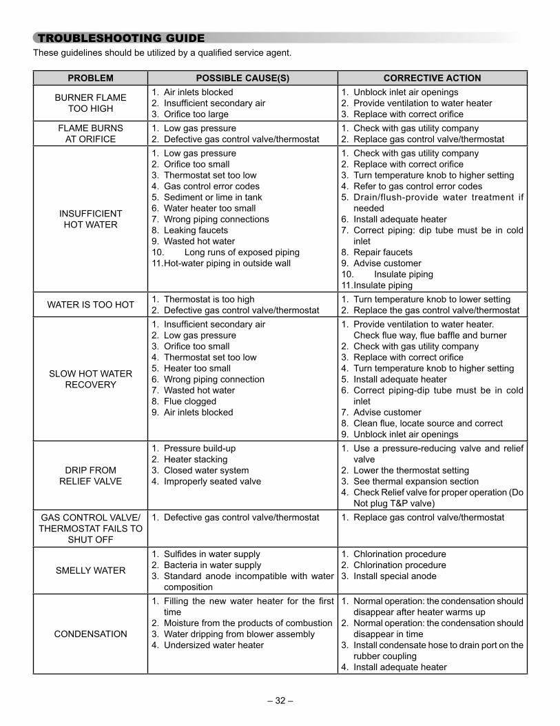
TROUBLESHOOTING GUIDEThese guidelines should be utilized by a qualifi ed service agent.
PROBLEM POSSIBLE CAUSE(S) CORRECTIVE ACTION
BURNER FLAME TOO HIGH
1. Air inlets blocked2. Insuffi cient secondary air3. Orifi ce too large
1. Unblock inlet air openings2. Provide ventilation to water heater3. Replace with correct orifi ce
FLAME BURNS AT ORIFICE
1. Low gas pressure2. Defective gas control valve/thermostat
1. Check with gas utility company2. Replace gas control valve/thermostat
INSUFFICIENT HOT WATER
1. Low gas pressure2. Orifi ce too small3. Thermostat set too low4. Gas control error codes5. Sediment or lime in tank6. Water heater too small7. Wrong piping connections8. Leaking faucets9. Wasted hot water10. Long runs of exposed piping11. Hot-water piping in outside wall
1. Check with gas utility company2. Replace with correct orifi ce3. Turn temperature knob to higher setting4. Refer to gas control error codes5. Drain/flush-provide water treatment if
needed6. Install adequate heater7. Correct piping: dip tube must be in cold
inlet8. Repair faucets9. Advise customer10. Insulate piping11. Insulate piping
WATER IS TOO HOT 1. Thermostat is too high2. Defective gas control valve/thermostat
1. Turn temperature knob to lower setting2. Replace the gas control valve/thermostat
SLOW HOT WATER RECOVERY
1. Insuffi cient secondary air2. Low gas pressure3. Orifi ce too small4. Thermostat set too low5. Heater too small6. Wrong piping connection7. Wasted hot water8. Flue clogged9. Air inlets blocked
1. Provide ventilation to water heater. Check fl ue way, fl ue baffl e and burner
2. Check with gas utility company3. Replace with correct orifi ce4. Turn temperature knob to higher setting5. Install adequate heater6. Correct piping-dip tube must be in cold
inlet7. Advise customer8. Clean fl ue, locate source and correct9. Unblock inlet air openings
DRIP FROM RELIEF VALVE
1. Pressure build-up2. Heater stacking3. Closed water system4. Improperly seated valve
1. Use a pressure-reducing valve and relief valve
2. Lower the thermostat setting3. See thermal expansion section4. Check Relief valve for proper operation (Do
Not plug T&P valve)GAS CONTROL VALVE/THERMOSTAT FAILS TO
SHUT OFF
1. Defective gas control valve/thermostat 1. Replace gas control valve/thermostat
SMELLY WATER
1. Sulfi des in water supply2. Bacteria in water supply3. Standard anode incompatible with water
composition
1. Chlorination procedure2. Chlorination procedure3. Install special anode
CONDENSATION
1. Filling the new water heater for the fi rst time
2. Moisture from the products of combustion3. Water dripping from blower assembly4. Undersized water heater
1. Normal operation: the condensation should disappear after heater warms up
2. Normal operation: the condensation should disappear in time
3. Install condensate hose to drain port on the rubber coupling
4. Install adequate heater
– 32 –
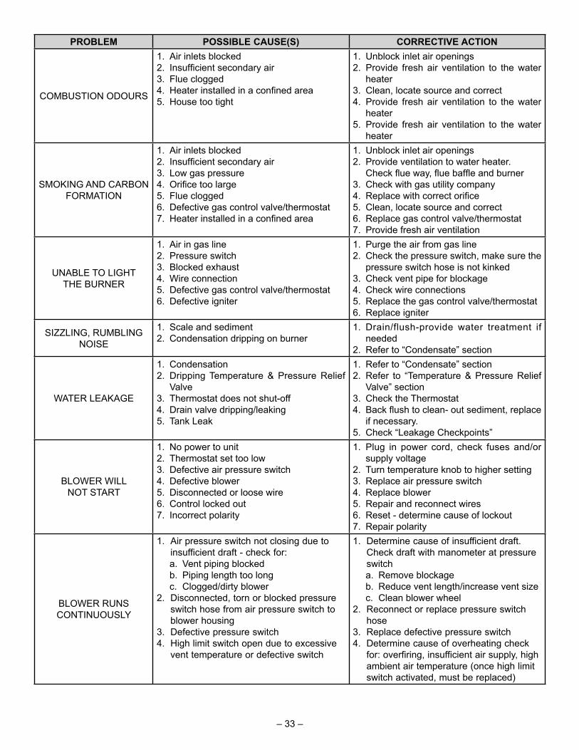
PROBLEM POSSIBLE CAUSE(S) CORRECTIVE ACTION
COMBUSTION ODOURS
1. Air inlets blocked2. Insuffi cient secondary air3. Flue clogged4. Heater installed in a confi ned area5. House too tight
1. Unblock inlet air openings2. Provide fresh air ventilation to the water
heater3. Clean, locate source and correct4. Provide fresh air ventilation to the water
heater5. Provide fresh air ventilation to the water
heater
SMOKING AND CARBON FORMATION
1. Air inlets blocked2. Insuffi cient secondary air3. Low gas pressure4. Orifi ce too large5. Flue clogged6. Defective gas control valve/thermostat7. Heater installed in a confi ned area
1. Unblock inlet air openings2. Provide ventilation to water heater.
Check fl ue way, fl ue baffl e and burner3. Check with gas utility company4. Replace with correct orifi ce5. Clean, locate source and correct6. Replace gas control valve/thermostat7. Provide fresh air ventilation
UNABLE TO LIGHT THE BURNER
1. Air in gas line2. Pressure switch3. Blocked exhaust4. Wire connection5. Defective gas control valve/thermostat6. Defective igniter
1. Purge the air from gas line2. Check the pressure switch, make sure the
pressure switch hose is not kinked3. Check vent pipe for blockage4. Check wire connections5. Replace the gas control valve/thermostat6. Replace igniter
SIZZLING, RUMBLING NOISE
1. Scale and sediment2. Condensation dripping on burner
1. Drain/flush-provide water treatment if needed
2. Refer to “Condensate” section
WATER LEAKAGE
1. Condensation2. Dripping Temperature & Pressure Relief
Valve3. Thermostat does not shut-off4. Drain valve dripping/leaking5. Tank Leak
1. Refer to “Condensate” section2. Refer to “Temperature & Pressure Relief
Valve” section3. Check the Thermostat4. Back fl ush to clean- out sediment, replace
if necessary.5. Check “Leakage Checkpoints”
BLOWER WILL NOT START
1. No power to unit2. Thermostat set too low3. Defective air pressure switch4. Defective blower5. Disconnected or loose wire6. Control locked out7. Incorrect polarity
1. Plug in power cord, check fuses and/or supply voltage
2. Turn temperature knob to higher setting3. Replace air pressure switch4. Replace blower5. Repair and reconnect wires6. Reset - determine cause of lockout7. Repair polarity
BLOWER RUNS CONTINUOUSLY
1. Air pressure switch not closing due to insufficient draft - check for:
a. Vent piping blocked b. Piping length too long c. Clogged/dirty blower2. Disconnected, torn or blocked pressure
switch hose from air pressure switch to blower housing
3. Defective pressure switch4. High limit switch open due to excessive
vent temperature or defective switch
1. Determine cause of insufficient draft. Check draft with manometer at pressure switch
a. Remove blockage b. Reduce vent length/increase vent size c. Clean blower wheel2. Reconnect or replace pressure switch
hose3. Replace defective pressure switch4. Determine cause of overheating check
for: overfiring, insufficient air supply, high ambient air temperature (once high limit switch activated, must be replaced)
– 33 –

PROBLEM POSSIBLE CAUSE(S) CORRECTIVE ACTIONHOT SURFACE IGNITER
NOT GLOWING FOLLOWING WARM-UP
PERIOD
1. 120VAC polarity reversed at 120VAC outlet receptacle
2. Defective hot surface igniter3. Defective gas control valve/thermostat
1. Reverse polari ty at 120VAC outlet receptacle
2. Replace igniter3. Replace gas control valve/thermostat
VENT PIPE TOO HOT(ABOVE 149°F)
1. Blower does not run when heater fi red2. Not enough dilution air to mix with fl ue
gases3. Air in room too hot for mixing with fl ue
gases4. Wrong burner orifi ce5. Baffl e incorrect or missing
1. Refer to “BLOWER WILL NOT START” problem
2. Proper air circulation must be provided for combustion and dilution of fl ue temp
3. Room air to be used for dilution with combustion products in fl ue should be less than 90°F
4. Install correct orifi ce.5. Contact water heater supplier
Ignition State and Timing
IGNITION STATE TIMING
Pre-purge5 seconds (NG models)15 seconds (LP models)
HSI Warmup 10 secondsIgnition Activation Period (IAP) 3.5 seconds maximum
Flame Recognition Period (FRP) 0.5 second
Trial For Ignition IAP + FRPFlame Stabilization Period Not Applicable
Inter-purge 30 seconds Flame Failure Response Time
2 seconds max (@ 1uA fl ame current)
Post-purge 30 seconds PS Prove Period 2 minutesPS Fault Delay (failed open/closed) 2 minutes
Soft Lockout 20 minutes Energy Cut Off(ECO) Limit Lockout Indefi nite
Flammable Vapour Sensor Lockout
Indefi nite (follow defi ned procedure to restart)
Hardware Fault Lockout Indefi nite (clear fault to restart in 15 seconds or less)
– 34 –

System Error CodesThe micro-controller inside the gas control monitors the fl ammable vapour safety features, the ignition sequence, temperature settings and overall operation of the heater. If any of these parameters does not operate properly the controller will shut down the water heater, diagnose the failure and fl ash an error code. Table 2 lists the System Status Codes for the Honeywell control. Refer to Table 2 and to the “Trouble Shooting Guide” to diagnose the problem before attempting corrective action. See also “Flammable Vapour Sensor” and “Resettable Lockout”.
Honeywell Troubleshooting Chart - User Control
LED Flash Sequence Control StatusShort fl ash once every four seconds
IDLE (no call for heat, no fault conditions)
“Heartbeat”, alternates bright/dim
Call For Heat (no fault conditions)
One Flash, three second pause
Low Flame Signal (control continues to operate)
Two Flash, three second pause
Pressure Switch Failed Closed
Three Flash, three second pause Pressure Switch Failed Open
Four Flash, three second pause
ECO (Energy Cut Off) Limit Lockoutthermostat temperature limit was exceeded.
Five Flash, three second pause Flame Out Of Sequence
Six-One Flash, three second pause
Soft Lockout - Retry Limit - Failed TFI
Six-Two Flash, three second pause
Soft Lockout - Recycle Limit - PS/Limit opened
Six-Three Flash, three second pause
Soft Lockout - Recycle Limit - Flame Lost
Six-Four Flash, three second pause
Soft Lockout - Flame out of Sequence Sensed
Seven Flash, three second pause
Flammable Vapour Sensor Lockout
Eight-One Flash, three second pause FVS Fault Detected
Eight-Two Flash, three second pause
Temperature Sensor Fault Detected
Eight-Three Flash, three second pause Electronics Fault Detected
Eight-Four Flash, three second pause Valve Fault Detected
Table 2 – 35 –
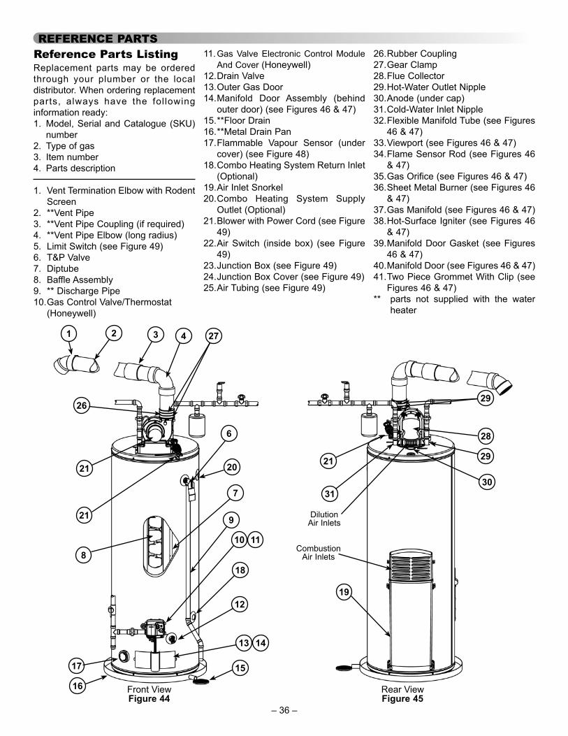
REFERENCE PARTS Reference Parts ListingReplacement parts may be ordered through your plumber or the local distributor. When ordering replacement parts, always have the fol lowing information ready:1. Model, Serial and Catalogue (SKU)
number2. Type of gas3. Item number4. Parts description
1. Vent Termination Elbow with Rodent Screen
2. **Vent Pipe3. **Vent Pipe Coupling (if required)4. **Vent Pipe Elbow (long radius)5. Limit Switch (see Figure 49)6. T&P Valve7. Diptube8. Baffle Assembly9. ** Discharge Pipe10. Gas Control Valve/Thermostat
(Honeywell)
11. Gas Valve Electronic Control Module And Cover (Honeywell)
12. Drain Valve13. Outer Gas Door14. Manifold Door Assembly (behind
outer door) (see Figures 46 & 47)15. **Floor Drain16. **Metal Drain Pan17. Flammable Vapour Sensor (under
cover) (see Figure 48)18. Combo Heating System Return Inlet
(Optional)19. Air Inlet Snorkel20. Combo Heating System Supply
Outlet (Optional)21. Blower with Power Cord (see Figure
49)22. Air Switch (inside box) (see Figure
49)23. Junction Box (see Figure 49)24. Junction Box Cover (see Figure 49)25. Air Tubing (see Figure 49)
26. Rubber Coupling27. Gear Clamp28. Flue Collector29. Hot-Water Outlet Nipple30. Anode (under cap)31. Cold-Water Inlet Nipple32. Flexible Manifold Tube (see Figures
46 & 47)33. Viewport (see Figures 46 & 47)34. Flame Sensor Rod (see Figures 46
& 47)35. Gas Orifice (see Figures 46 & 47)36. Sheet Metal Burner (see Figures 46
& 47)37. Gas Manifold (see Figures 46 & 47)38. Hot-Surface Igniter (see Figures 46
& 47)39. Manifold Door Gasket (see Figures
46 & 47)40. Manifold Door (see Figures 46 & 47)41. Two Piece Grommet With Clip (see
Figures 46 & 47)** parts not supplied with the water
heater
Front View Rear ViewFigure 44 Figure 45
1
6
9
10
12
13
16
17
20
18
2 3 4
21
27
21
8
7
14
11
15
26
19
21 29
3130
Combustion Air Inlets
29
28
Dilution Air Inlets
– 36 –

3234
36
3338
39
37
35
4041
Natural gas and Propane main burner with igniter assembly for 40k to 50k Btu/hr models
Flare Nut**
*
Figure 46
32 34
36
3338
39
37
35
4041
Natural gas and Propane main burner with igniter assembly for 60k to 75k Btu/hr models
Flare Nut**
*
Figure 47
17
Figure 48
25
23
24
22
5
26
27
Figure 49
Notes: * Natural gas models have Right-hand thread, Propane models have Left-hand thread.
** For Natural gas models the Flare Nut has Right-hand thread. For Propane models the Flare Nut has Left-hand thread.
– 37 –

NOTES
– 38 –

NOTES
– 39 –