Embed Size (px)
Citation preview
1
PP-H (100)
•Gamma dimensionale da d 20 mm a d 110 mm.
•Materiale: polipropilene PP-H•Resistenza a pressioni di eserci-
zio fino a 10 bar a 20°C •Temperatura massima di eserci-
zio: 100 °C.•Sistema di giunzione: saldatura
nel bicchiere o filettatura.
• Size range: from d 20 mm up to d 110 mm.
• Material: polypropylene PP-H• Maximum working pressure: 10
bar at 20°C• Maximum working temperature:
100 °C.• Jointing by socket fusion techni-
que or threaded connections.
• Gamme dimensionnelle de d 20 mm à d 110 mm.
• Matériau: polypropylène PP-H• Pression de service jusqu’à 10
bar à 20°C• Température de service jusqu’à
100 °C.• Système de jonction par soudu-
re dans l’emboîture aussi bien que par filetage.
• Abmessungen von d 20 mm bis d 110 mm.• Material: Polypropylen PP-H• Zulässige Betriebsüberdruck 10
bar bei wasser 20° C. • Max Betriebstemperatur: 100 °C.• Verbindung durch Heizelementmuffen- schweißen oder Gewinde.
d diametro nominale esterno del tubo in mm
DN diametro nominale interno in mm
R dimensione nominale della filet-tatura in pollici
PN pressione nominale in bar (pressione max di esercizio a 20° C - acqua - 50 anni)
g peso in grammin numero di foriM bulloni
C codice di riferimento O-ring
PPH polipropilene omopo-limero-MRS-10
MRS Minimo valore garan-tito del carico di rottu-ra del materiale a 20° C - acqua per 50 anni di servizio
FPM fluoroelastomero
EPDM elastomero etilene propilenePVC-C cloruro di polivinile
d nominal outside dia- meter of the pipe in mm
DN nominal internal dia- meter in mm
R nominal size of the thread in inches
PN nominal pressure in bar (max. working pressure at 20° C - water - 50 years)
g weight in gramsn number of holesM bolts
C O-ring code
PPH homopolymer poly-propylene MRS-10
MRS Minimum required strenght for water at 20° C for 50 years
FPM vinylidene fluoride rubber
EPDM ethylene propylene rubber
C-PVC chlorinated polyvynil chloride
d diamètre extérieur nominal du tube en mm
DN diamètre nominal interieur en mm
R dimension nominale du filetage en pouces
PN pression nominale en bar (pression de service max à 20° C - eau - 50 années)
g poids en grammesn nombre de trousM boulons
C codification joint
PPH polypropylène homo-polymère MRS-10
MRS Tension de ropture minimale (avec de l’eau à 20°C a 50
années)
FPM fluorélastomère de vinylidèneEPDM élastomère ethylène- propylène PVC-C polychlorure de vinyle
surchloré
d Rohraußendurchmesser, mmDN Nennweite, mm R Gewinde in Inches
PN Nenndruck, in bar (max Betriebsdruck
bei Wasser 20° C - 50 Jahre)g Gewicht in Grammn LochzahlM Schrauben (metrisches
Gewinde)C Kode O-Ring
PPH Polypropylen Homopoly-merisat
MRS-10MRS Erforderliche
Mindestfestigkeit bei Wasser 20°C -
50 Jahre
FPM Fluor-Kautschuk
EPDM Ethylen-Propylen- KautschukPVC-C Polyvinylchlorid, chlo-
riert
Raccordi per sal-datura nel bicchie-re in PP-H (100)
PP-H (100) socket welding fittings
Formteile zumHeizelementmuffen-schweißen aus PP-H (100)
Raccords pour sou-dure dans l’emboîtu-re en PP-H (100)
LEGENDA
2
PP-H (100)
2
PP-H (100)
La FIP ha approntato una gamma completa di raccordi (tipo B) in accordo con le seguenti norme:
• saldatura nel bicchiere: DIN 16962, UNIPLAST 383, accop-piabili con tubi secondo le norme: ISO DIS 3609, DIN 8077, UNI 8318, BS 4991, ISO DIS 15494
• filettatura: UNI ISO 228/1, DIN 2999, BS 21.
FIP produces a complete range of fittings (type B) according to the following standards:
• polyfusion sockets: DIN 16962, UNIPLAST 383, coupling to pipes complying with: ISO DIS 3609, DIN 8077, UNI 8318, BS 4991, ISO DIS 15494
• threaded coupling: UNI ISO 228/1, DIN 2999, BS 21.
FIP à réalisé une gamme com-plète de raccords (type B) confor-mes aux normes suivantes:
• soudure suivant la DIN 16962, UNIPLAST 383, qui peuvent être soudès avec des tubes conformes aux normes: ISO DIS 3609, DIN 8077, UNI 8318, BS 4991, ISO DIS 15494
• filetage: UNI ISO 228/1, DIN 2999, BS 21.
FIP produziert ein komplettes Programm Formstücke (Type B) welcher folgenden Normen entspricht:
• Schweißanschlüsse: DIN 16962, UNIPLAST 383, für die Verbindung mit Rohren nach: ISO DIS 3609, DIN 8077, UNI 8318, BS 4991, ISO DIS 15494
• Gewindeanschlüsse: UNI ISO 228/1, DIN 2999, BS 21.
Dimensioni Dimensions DimensionenDimensions
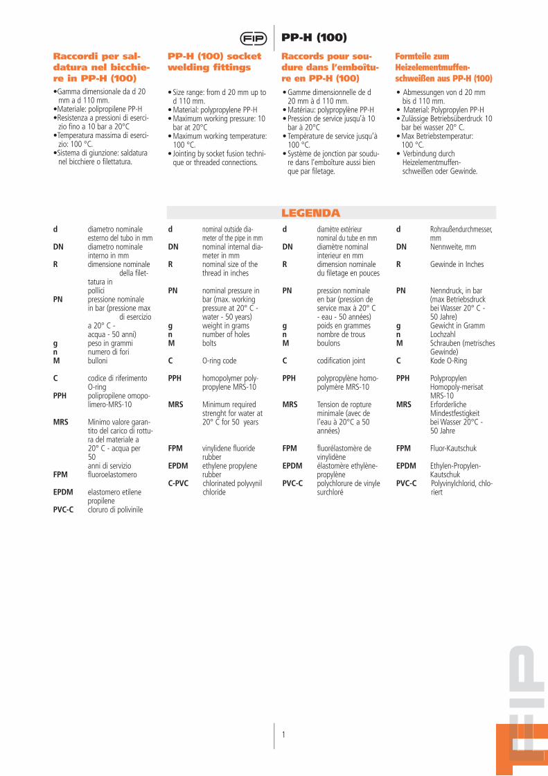
GIMGOMITO A 90°per saldatura nel bicchiere
90° ELBOWfor socket fusion
COUDE À 90°femelle à souder
WINKEL 90°für Muffenschweißung27.010.01
g
14233764
105180300455815
Z
13.016.020.022.027.533.542.049.059.0
H
27.532.037.042.551.061.073.084.5
100.5
E
27.533.541.551.563.578.592.5
110.5135.0
d
2025324050637590
110
Variazione della pressione in funzione della temperatura per acqua o fluidi non pericolosi nei confronti dei quali il PP è classificato CHIMICAMENTE RESISTENTE. Vedere il prospetto “Guida alla resistenza chimica”. In altri casi è richiesta un’ade-guata diminuzione della pressio-ne nominale PN.____ 10 anni - - - - 50 anni
Pressure/temperature rating for water and harmless fluids to which PP is RESISTANT. See “A guide to chemical resistance”. In other cases a reduction of the rated PN is required.____ 10 years - - - - 50 years
Variation de la pression en fonction de la température pour l’eau et les fluides non agressifs pour lequel le PP est considéré CHIMIQUEMENT RESISTANT. Voir “Guide de résistance chimique”. Pour les autres cas une diminution du PN est nécessaire.____ 10 années - - - - 50 années
Druck/Temperatur Diagramm für Wasser und ungefähr-liche Medien wogegen die PP beständig ist (siehe Beständigkeitsliste). In allen anderen Fällen ist eine Reduzierung der Druckstufe erforderlich.____ 10 Jahre - - - - 50 Jahre
1
DatiTecnici
TechnicalData
TechnischeDaten
DonnéesTechniques
1bar
10
8
6
4
2
0
-20 0 20 40 °C60 10080
PN 10
pres
sione
di e
serc
izio
- wor
king
pre
ssur
epr
essio
n de
ser
vice
- Bet
riebs
druc
k
temperatura di esercizio - working temperaturetempérature de service - Betriebstemperatur
2
PP-H (100)
3
PP-H (100)
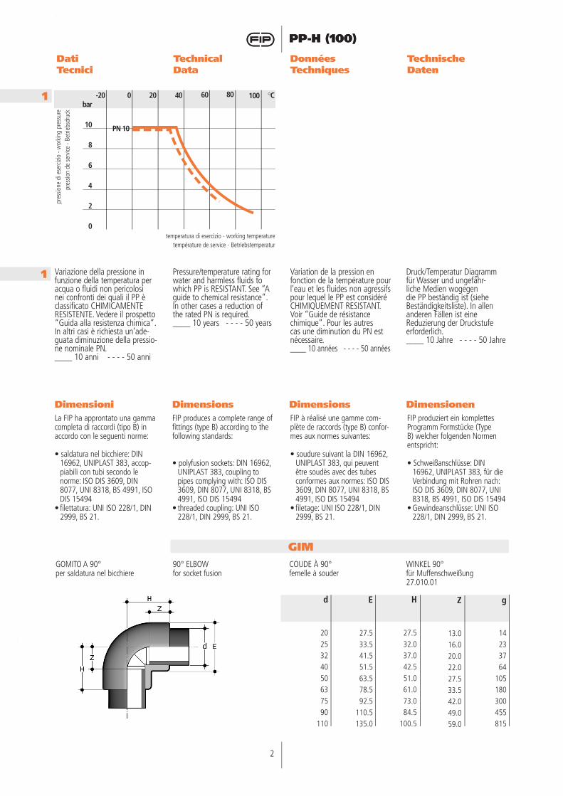
RIMRIDUZIONEper saldatura nel bicchiered maschio, d1 ridotto femmina
REDUCING PIECEfor socket fusion, d male, d1reduced female
REDUCTIONmâle à souder sur le 1er dfemelle à souder sur led1 reduit
REDUZIERSTÜCKfür Muffenschweißung, d Aussengewinde, d1 Innengewinde reduziert 27.091.03
g
101317242739446976
106115156175290305
Z
24.530.030.033.033.036.036.044.044.047.047.056.056.066.066.0
H
39.043.046.048.051.054.056.561.067.569.074.582.087.593.0
101.5
E
28.035.533.542.042.051.551.565.065.077.577.591.591.5
111.5111.5
d x d1
25 x 2032 x 2032 x 2540 x 2540 x 3250 x 3250 x 4063 x 3263 x 5075 x 5075 x 6390 x 6390 x 75
110 x 63110 x 90
TIMTI A 90°per saldatura nel bicchiere
90° TEEfor socket fusion
TE À 90°femelles à souder
T-STÜCK 90°für Muffenschweißung27.020.01
g
19304780
145250370560990
Z
13.015.519.022.528.535.040.046.058.0
H
27.531.537.043.052.062.571.081.599.5
E
27.533.541.552.064.079.592.5
110.5134.5
d
2025324050637590
110
HIMGOMITO A 45°per saldatura nel bicchiere
45° ELBOWfor socket fusion
COUDE À 45°femelle à souder
winkel 45°für Muffenschweißung
g
12193357
105182220410590
Z
6.58.5
12.015.019.023.538,546,056,0
H
21.024.529.035.542.551.071,082,598,7
E
27.533.542.051.563.079.092,0
113,7135,0
d
2025324050637590
110
4
PP-H (100)
4
PP-H (100)
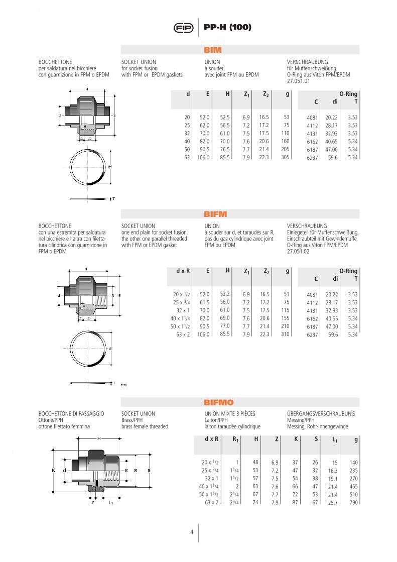
BIM
BIFM
BOCCHETTONEper saldatura nel bicchiere con guarnizione in FPM o EPDM
SOCKET UNIONfor socket fusionwith FPM or EPDM gaskets
UNIONà souderavec joint FPM ou EPDM
VERSCHRAUBUNGfür MuffenschweißungO-Ring aus Viton FPM/EPDM27.051.01
BOCCHETTONEcon una estremità per saldatura nel bicchiere e l’altra con filetta-tura cilindrica con guarnizione in FPM o EPDM
SOCKET UNIONone end plain for socket fusion, the other one parallel threaded with FPM or EPDM gasket
UNIONà souder sur d, et taraudés sur R, pas du gaz cylindrique avec joint FPM ou EPDM
VERSCHRAUBUNGEinlegeteil für Muffenschweißung, Einschraubteil mit Gewindemuffe, O-Ring aus Viton FPM/EPDM27.051.02
BIFMOBOCCHETTONE DI PASSAGGIOOttone/PPHottone filettato femmina
SOCKET UNIONBrass/PPHbrass female threaded
UNION MIXTE 3 PIÈCESLaiton/PPHlaiton taraudée cylindrique
ÜBERGANGSVERSCHRAUBUNGMessing/PPHMessing, Rohr-Innengewinde
d
202532405063
Z1
6.97.27.57.67.77.9
H
52.556.561.070.076.585.5
g
5375
110160205305
E
52.062.070.082.090.5
106.0
Z2
16.517.217.520.621.422.3
C
408141124131616261876237
T
3.533.533.535.345.345.34
di
20.2228.1732.9340.6547.0059.6
O-Ring
d x R
20 x 1/225 x 3/4
32 x 140 x 11/450 x 11/2
63 x 2
Z1
6.97.27.57.67.77.9
H
52.256.061.069.077.085.5
g
5175
115155210310
E
52.061.570.082.090.5
106.0
Z2
16.517.217.520.621.422.3
C
408141124131616261876237
T
3.533.533.535.345.345.34
di
20.2228.1732.9340.6547.0059.6
O-Ring
g
140235270455510790
L1
1516.319.121.421.425.7
K
374754667287
S
263238475367
H
485357636774
Z
6.97.27.57.67.77.9
R1
111/411/2
221/423/4
d x R
20 x 1/225 x 3/4
32 x 140 x 11/450 x 11/2
63 x 2
4
PP-H (100)
5
PP-H (100)
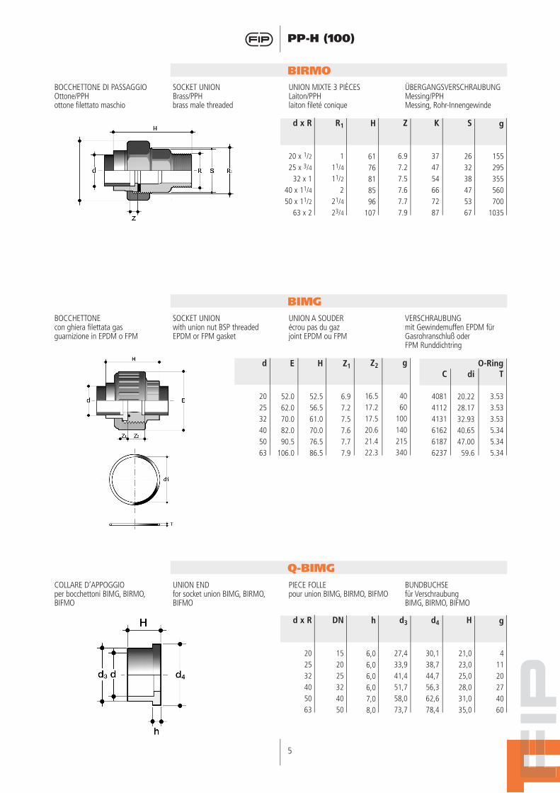
BIRMOBOCCHETTONE DI PASSAGGIOOttone/PPHottone filettato maschio
SOCKET UNIONBrass/PPHbrass male threaded
UNION MIXTE 3 PIÈCESLaiton/PPHlaiton fileté conique
ÜBERGANGSVERSCHRAUBUNGMessing/PPHMessing, Rohr-Innengewinde
BIMGBOCCHETTONEcon ghiera filettata gasguarnizione in EPDM o FPM
SOCKET UNIONwith union nut BSP threaded EPDM or FPM gasket
UNION A SOUDERécrou pas du gazjoint EPDM ou FPM
VERSCHRAUBUNGmit Gewindemuffen EPDM für Gasrohranschluß oderFPM Runddichtring
Q-BIMGCOLLARE D’APPOGGIOper bocchettoni BIMG, BIRMO, BIFMO
UNION ENDfor socket union BIMG, BIRMO, BIFMO
PIECE FOLLEpour union BIMG, BIRMO, BIFMO
BUNDBUCHSEfür VerschraubungBIMG, BIRMO, BIFMO
d
202532405063
Z1
6.97.27.57.67.77.9
H
52.556.561.070.076.586.5
g
4060
100140215340
E
52.062.070.082.090.5
106.0
Z2
16.517.217.520.621.422.3
C
408141124131616261876237
T
3.533.533.535.345.345.34
di
20.2228.1732.9340.6547.0059.6
O-Ring
g
155295355560700
1035
S
263238475367
Z
6.97.27.57.67.77.9
K
374754667287
H
6176818596
107
R1
111/411/2
221/423/4
d x R
20 x 1/225 x 3/4
32 x 140 x 11/450 x 11/2
63 x 2
g
41120274060
H
21,023,025,028,031,035,0
d3
27,433,941,451,758,073,7
d4
30,138,744,756,362,678,4
h
6,06,06,06,07,08,0
DN
152025324050
d x R
202532405063
6
PP-H (100)
6
PP-H (100)
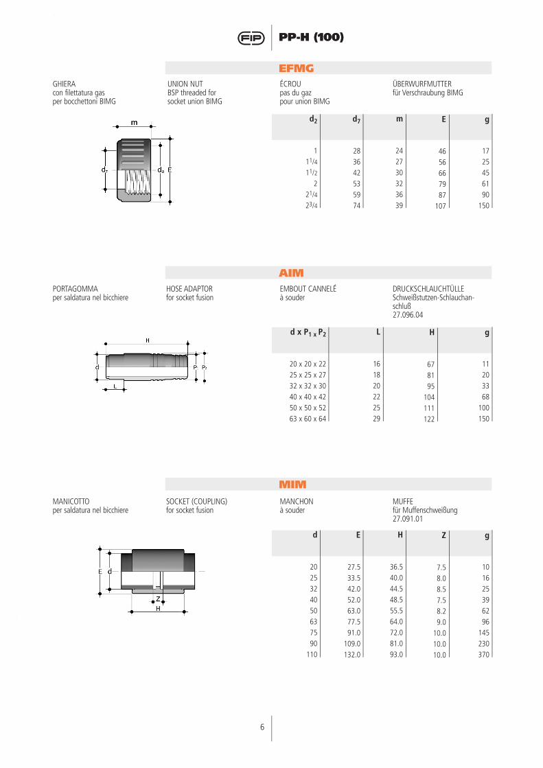
EFMGGHIERAcon filettatura gasper bocchettoni BIMG
UNION NUTBSP threaded forsocket union BIMG
ÉCROUpas du gazpour union BIMG
ÜBERWURFMUTTERfür Verschraubung BIMG
AIMPORTAGOMMAper saldatura nel bicchiere
HOSE ADAPTORfor socket fusion
EMBOUT CANNELÉà souder
DRUCKSCHLAUCHTÜLLESchweißstutzen-Schlauchan-schluß27.096.04
MIMMANICOTTOper saldatura nel bicchiere
SOCKET (COUPLING)for socket fusion
MANCHONà souder
MUFFEfür Muffenschweißung27.091.01
g
1725456190
150
E
4656667987
107
m
242730323639
d7
283642535974
d2
111/411/2
221/423/4
g
101625396296
145230370
Z
7.58.08.57.58.29.0
10.010.010.0
H
36.540.044.548.555.564.072.081.093.0
E
27.533.542.052.063.077.591.0
109.0132.0
d
2025324050637590
110
g
11203368
100150
H
678195
104111122
L
161820222529
d x P1 x P2
20 x 20 x 2225 x 25 x 2732 x 32 x 3040 x 40 x 4250 x 50 x 5263 x 60 x 64
6
PP-H (100)
7
PP-H (100)
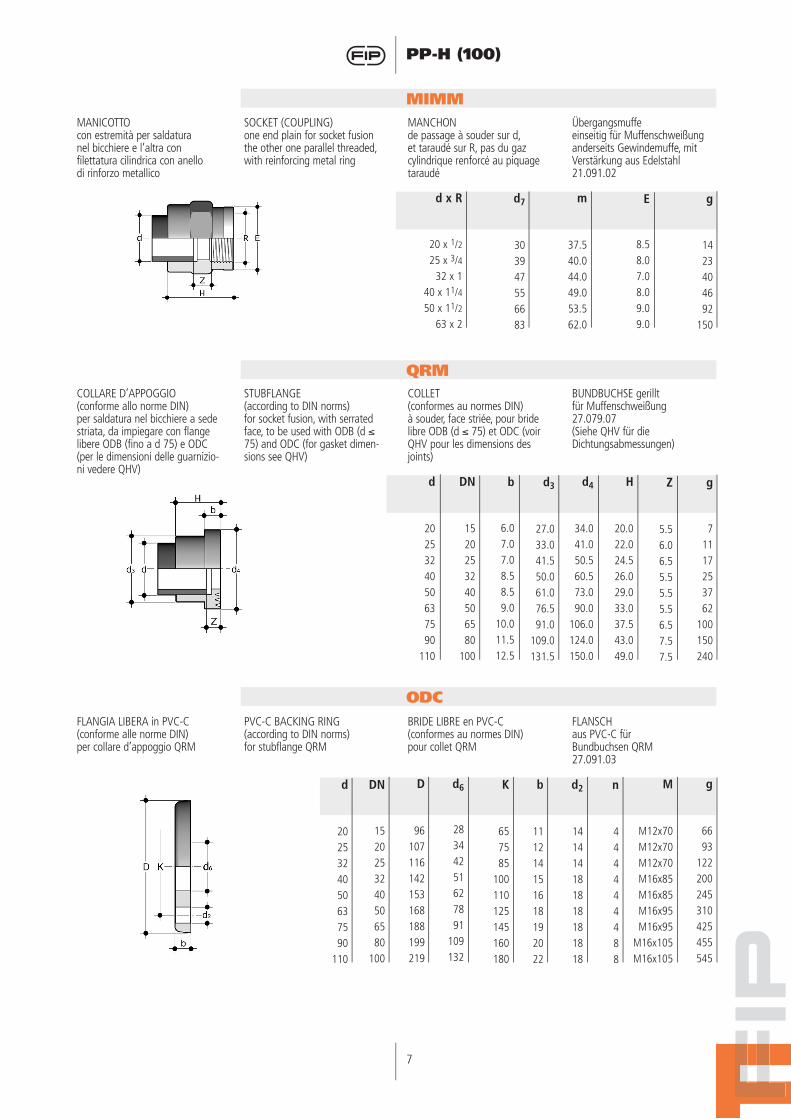
MIMMMANICOTTOcon estremità per saldaturanel bicchiere e l’altra confilettatura cilindrica con anello di rinforzo metallico
SOCKET (COUPLING)one end plain for socket fusionthe other one parallel threaded, with reinforcing metal ring
MANCHONde passage à souder sur d, et taraudé sur R, pas du gaz cylindrique renforcé au piquage taraudé
Übergangsmuffeeinseitig für Muffenschweißunganderseits Gewindemuffe, mit Verstärkung aus Edelstahl21.091.02
FLANGIA LIBERA in PVC-C(conforme alle norme DIN)per collare d’appoggio QRM
PVC-C BACKING RING(according to DIN norms)for stubflange QRM
BRIDE LIBRE en PVC-C(conformes au normes DIN)pour collet QRM
FLANSCHaus PVC-C fürBundbuchsen QRM27.091.03
QRMCOLLARE D’APPOGGIO (conforme allo norme DIN)per saldatura nel bicchiere a sede striata, da impiegare con flange libere ODB (fino a d 75) e ODC (per le dimensioni delle guarnizio-ni vedere QHV)
STUBFLANGE(according to DIN norms)for socket fusion, with serrated face, to be used with ODB (d ≤ 75) and ODC (for gasket dimen-sions see QHV)
COLLET(conformes au normes DIN)à souder, face striée, pour bride libre ODB (d ≤ 75) et ODC (voir QHV pour les dimensions des joints)
BUNDBUCHSE gerilltfür Muffenschweißung27.079.07(Siehe QHV für die Dichtungsabmessungen)
ODC
g
1423404692
150
E
8.58.07.08.09.09.0
m
37.540.044.049.053.562.0
d7
303947556683
d x R
20 x 1/225 x 3/4
32 x 140 x 11/450 x 11/2
63 x 2
g
71117253762
100150240
Z
5.56.06.55.55.55.56.57.57.5
d4
34.041.050.560.573.090.0
106.0124.0150.0
H
20.022.024.526.029.033.037.543.049.0
b
6.07.07.08.58.59.0
10.011.512.5
d3
27.033.041.550.061.076.591.0
109.0131.5
DN
1520253240506580
100
d
2025324050637590
110
K
657585
100110125145160180
D
96107116142153168188199219
DN
1520253240506580
100
d
2025324050637590
110
d6
28344251627891
109132
n
444444488
d2
141414181818181818
g
6693
122200245310425455545
b
111214151618192022
M
M12x70M12x70M12x70M16x85M16x85M16x95M16x95
M16x105M16x105
8
PP-H (100)
8
PP-H (100)
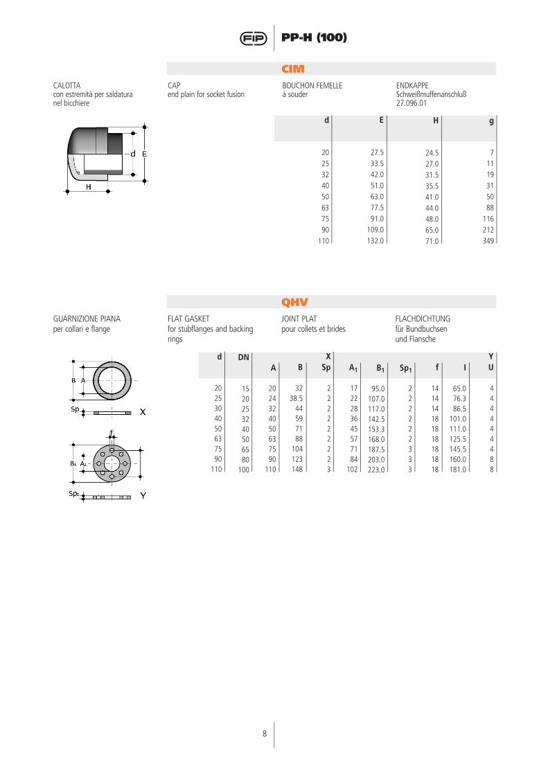
CALOTTAcon estremità per saldaturanel bicchiere
CAPend plain for socket fusion
BOUCHON FEMELLEà souder
ENDKAPPESchweißmuffenanschluß27.096.01
CIM
GUARNIZIONE PIANAper collari e flange
FLAT GASKETfor stubflanges and backing rings
JOINT PLATpour collets et brides
FLACHDICHTUNGfür Bundbuchsenund Flansche
QHV
g
71119315088
116212349
H
24.527.031.535.541.044.048.065.071.0
E
27.533.542.051.063.077.591.0
109.0132.0
d
2025324050637590
110
A1
1722283645577184
102
B
3238.5
44597188
104123148
A
2024324050637590
110
DN
1520253240506580
100
d
2025304050637590
110
Sp
222222223
f
141414181818181818
Sp1
222222333
U
444444488
B1
95.0107.0117.0142.5153.3168.0187.5203.0223.0
I
65.076.386.5
101.0111.0125.5145.5160.0181.0
X Y
8
PP-H (100)
9
PP-H (100)
La saldatura termica nel bicchiereLa saldatura termica a caldo nel bicchiere prevede la fusione del tubo entro il bicchiere del raccor-do. La giunzione viene ottenuta portando contemporaneamente a fusione le superfici maschio e femmina da saldare tramite appo-site apparecchiature riscaldanti di tipo manuale o automatico. Tali macchine sono, nella forma più semplice, costituite da una piastra termica sulla quale sono montate delle bussole di fusione. Un ade-guato sistema di riscaldamento, corredato da un controllore auto-matico di temperatura completa l’apparecchiatura. Nessun mate-riale di apporto è richiesto per effettuare la saldatura termica. La saldatura termica nel bicchiere non diminuisce il grado di resi-stenza chimica del polipropilene e mantiene inalterati i requisiti di resistenza a pressione interna dei tubi e dei raccordi accoppiati. Il tubo che deve essere saldato va tagliato, smussato ed even-tualmente raschiato. Superficie esterna del tubo ed interna del raccordo vanno accuratamente pulite e sulle superfici esterne di tubo e raccordo è utile eseguire una tacca di riferimento per evi-tare di ruotare gli stessi mentre si esegue la giunzione. Il passo successivo è quello di inserire il tubo nella bussola femmina ed il raccordo nella bussola maschio e di mantenerveli per un tempo minimo di riscaldamento; trascor-so tale tempo occorre estrarre rapidamente gli elementi dalle bussole ed inserire il tubo nel raccordo per l’intera lunghezza di inserzione precedentemente sta-bilita, rispettando l’allineamento delle tacche di riferimento. Quindi è necessario sostenere gli elemen-ti giuntati per 15 secondi circa e lasciarli raffreddare a temperatura ambiente senza ricorrere a ven-tilazione oppure a immersione in acqua.
Fusion Socket welding
Socket welding involves fusing of the pipe in the socket of the fitting. The joint is made by simul-taneously fusing the male and female surfaces by means of spe-cial manual or automatic heating devices. The welding appliances, in their simplest form, are compo-sed of a heating surface on which a series of heating bushes are mounted. The appliance is com-pleted by an appropriate heating system complete with automatic temperature controller. No addi-tional materials are required for this type of welding. Socket wel-ding does not affect the chemical resistance of the polypropylene, and nor does it influence the chemical resistance or pressure resistance of the assembled pipes and fittings. The pipe to be welded must be cut, chamfered and peeled if necessary. The external surface of the pipe and internal surface of the fitting must be carefully cleaned, and the external sur-faces of pipe and fitting can be marked with a reference notch to eliminate the risk of inadvertent rotation while the joint is setting. The next step is to insert the pipe in the heating bush and the fitting in the heating spigot and hold them in position for the necessary heating time; when this time has elapsed the two parts must be quickly removed from the bushes and then the pipe inserted into the fitting to the full previously determined insertion length, ensuring the reference marks are correctly aligned. The two elements must be supported for approximately 15 seconds after initial insertion and then left to cool at ambient temperature without using forced air flows or water immersion.
La soudure dans l’emboîture
La soudure dans l’emboîture prévoit la fusion du tube à l’in-térieur du raccord. On obtient la jonction en amenant simul-tanément au point de fusion les surfaces mâle et femelle à souder à travers des appareils chauffants spéciaux de type manuel ou automatique. Ces machines com-prennent, dans la forme la plus simple, une plaque thermique sur laquelle sont montées des douilles de fusion. Un système de chauffage approprié et équipé d’un contrôleur automatique de température complète l’appareil. Aucun matériau d’apport n’est nécessaire pour effectuer la sou-dure dans l’emboîture. La soudure dans l’emboîture ne réduit pas le degré de résistance chimique du polypropylène et maintient les conditions de résistance à la pression interne des Tube et des raccords accouplés inaltérée. Le tube qui doit être soudé est préa-lablement coupé, chanfreiné et éventuellement alésé. Les surfa-ces extérieure du tube et intérieu-re du raccord sont nettoyées à fond; de plus, il est utile de marquer un point de repère sur les surfaces extérieures du tube et du raccord pour éviter de les tourner lors de la jonction. L’étape suivante est celle de l’introduction du tube dans la douille femelle et du raccord dans la douille m-âle ; maintenir ces éléments dans cette position le temps nécessaire pour qu’ils chauffent, après quoi, les dégager rapidement des douilles et introduire le tube dans le raccord sur toute la longueur préalablement déterminée, en respectant l’alignement des repères. Maintenir les éléments accouplés pendant 15 secondes environ puis les laisser refroidir à température ambiante sans avoir recours à la ventilation ou à l’im-mersion dans l’eau.
Das Heizelementmuffen-schweißenBeim Heizelementmuffen-schweißen wird das anplasti-fizierte Rohr in die ebenfalls anplastifizierte Muffe gefügt. Die Schweißverbindung wird durch das aufschmelzen der Oberflächen im Kontaktbereich der beiden Schweißpartner, mittels speziel-len, manuell oder automatisch betätigter Heizelemente, erzielt. Diese Geräte bestehen, in der einfachsten Ausführung, aus einem Heizspiegel, auf dem einseitig jeweils ein Heizdorn und eine Heizbuchse montiert sind. Vervollständigt wird das Heizelement durch eine auto-matische Temperaturregeleinheit. Zur Durchführung der Schweißung ist kein Zusatzmaterial erfor-derlich. Ist die notwendige Schweißtemperatur erreicht, werden sowohl das Rohr in die Heizmuffe als auch die Muffe auf den Heizdorn gesteckt. Nach Ablauf der Aufwärmzeit, werden die beiden Schweißteile vom Heizelement genommen, ineinander gesteckt, und dann unter Druck gefügt. Danach läßt man die Teile langsam und spannungsfrei abkühlen. Das Heizelementmuffen-schweißen hat keinen Einfluß auf die che-mische Widerstandsfähigkeit des Poly-propylens und auch die Innendruckbelastbarkeit der Rohre und Formteile verringert nicht. Das zu schweißende Rohr ist planparallel abzuschneiden und gut anzufasen. Die Rohroberfläche und die Innenfläche der Muffe im Schweißbereich sind sorgfältig zu reinigen. Vor dem eigentlichen Schweißvorgang empfielt es sich die Einstecktiefe der Muffe auf dem Rohr zu kennzeichnen, damit das Rohr während des Fügevorgangs mit der entspre-chenden Tiefe in die Muffe eingesteckt wird. Danach beginnt der eigentliche Schweißvorgang, indem man das Rohr auf die vorgeheizten Heizbuchse führt und die Muffe auf den Heizdorn aufsteckt (Anwärmzeit). Unter leichtem Druck werden die bei-den Schweißpartner so lange in dieser Stellung gehalten, bis die Kontaktflächen anplastifiziert sind. Ist der notwendige Schweißwulst sichtbar, werden die beiden Schweißteile vom Heizelement abgezogen und möglichst rasch, gemäß der vorher angezeich-neten Länge zusammenge-fügt. Die beiden Teile müssen dann bei Zimmertemperatur und ohne Zuhilfenahme von Ventilatoren oder Wasserkühlung ca. 15 Sekunden in fixiertem Zustand unter entsprechendem Schweißdruck abgekühlt werden.
Istruzioni per la saldatura nel bicchiere
Socket weldinginstructions
Anleitung fürMuffenschweißung
Instructions pour la soudure dans l’emboîture
10
PP-H (100)
10
PP-H (100)
Procedura di saldatura a caldo nel bicchiere
Il metodo illustrato nel seguente paragrafo si applica solamente nella realizzazione di saldature termiche nel bicchiere che preve-dono l’impiego di apparecchiature saldanti di tipo manuale (FOTO 1). L’utilizzo di apparecchiature automatiche e semi-automatiche, particolarmente indicato per diametri superiori a 63mm, com-porta una conoscenza specifica dell’attrezzo, per cui si consiglia di attenersi alle indicazioni suggerite dal costruttore.
Fusion socket welding
The method described in the fol-lowing heading is applicable only when creating thermal welds in the socket that call for the use of manual type welding equipment (PHOTO 1). The use of automatic and semi-automatic appliances, which are particularly suitable for diameters greater than 63 mm, calls for a specific working know-ledge of the welding tool. In this case, adhere strictly to the tool manufactureris instructions.
Procédure de soudure dans l’emboîture
La méthode illustrée dans ce paragraphe s’applique unique-ment à la réalisation de soudures dans l’emboîture qui prévoient l’utilisation d’appareils de sou-dage de type manuel (PHOTO 1). L’utilisation d’appareils auto-matiques et semi-automatiques, particulièrement recommandés pour les diamètres supérieurs à 63 mm, comporte une con-naissance spécifique de l’outil; il est donc conseillé de respecter les indications suggérées par le constructeur.
Heizelementmuffenschweißverfahren
Im nachfolgend dargestellten Verfahren wird das Heizelementmuffenschweißen von Hand dargestellt. Das Bild (FOTO 1) zeigt einen Heizspiegel mit einem Heizdorn und einer Heizbuchse. Dieses Verfahren wird bei Dimensionen ( 63mm angewandt. Bei größeren Dimensionen wer-den Heizelementstumpfschweiß-maschinen (automatische Schweißmaschinen) eingesetzt, die jedoch spezifische Kenntnisse der Maschinen erfordern. Es emp-fielt sich daher, die Hinweise der Maschinen-hersteller genau zu beachten.
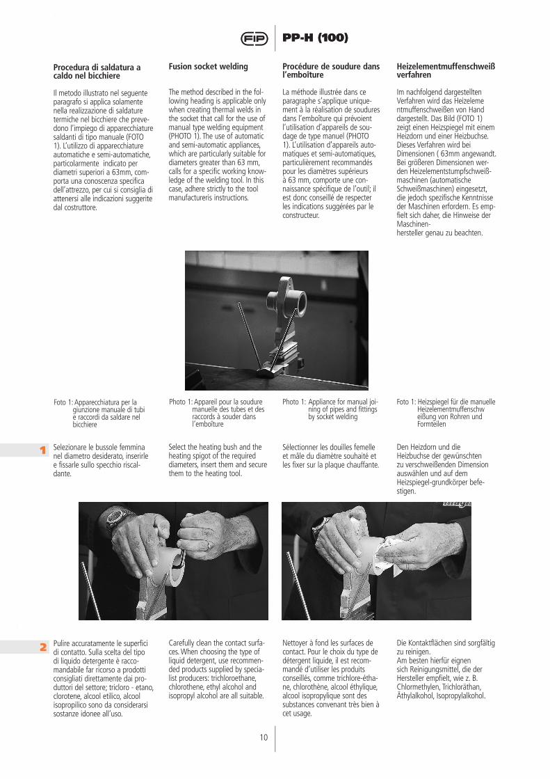
Selezionare le bussole femmina nel diametro desiderato, inserirle e fissarle sullo specchio riscal-dante.
Select the heating bush and the heating spigot of the required diameters, insert them and secure them to the heating tool.
Sélectionner les douilles femelle et mâle du diamètre souhaité et les fixer sur la plaque chauffante.
Den Heizdorn und die Heizbuchse der gewünschten zu verschweißenden Dimension auswählen und auf dem Heizspiegel-grundkörper befe-stigen.
Pulire accuratamente le superfici di contatto. Sulla scelta del tipo di liquido detergente è racco-mandabile far ricorso a prodotti consigliati direttamente dai pro-duttori del settore; tricloro - etano, clorotene, alcool etilico, alcool isopropilico sono da considerarsi sostanze idonee all’uso.
Carefully clean the contact surfa-ces. When choosing the type of liquid detergent, use recommen-ded products supplied by specia-list producers: trichloroethane, chlorothene, ethyl alcohol and isopropyl alcohol are all suitable.
Nettoyer à fond les surfaces de contact. Pour le choix du type de détergent liquide, il est recom-mandé d’utiliser les produits conseillés, comme trichlore-étha-ne, chlorothène, alcool éthylique, alcool isopropylique sont des substances convenant très bien à cet usage.
Die Kontaktflächen sind sorgfältig zu reinigen. Am besten hierfür eignen sich Reinigungsmittel, die der Hersteller empfielt, wie z. B. Chlormethylen, Trichloräthan, Äthylalkohol, Isopropylalkohol.
1
2
Foto 1: Apparecchiatura per la giunzione manuale di tubi e raccordi da saldare nel bicchiere
Photo 1: Appareil pour la soudure manuelle des tubes et des raccords à souder dans l’emboîture
Photo 1: Appliance for manual joi-ning of pipes and fittings by socket welding
Foto 1: Heizspiegel für die manuelle Heizelementmuffenschweißung von Rohren und Formteilen
10
PP-H (100)
11
PP-H (100)
Settare la temperatura dell’ele-mento riscaldante.L’intervallo di temperatura che va impostato sulla termoresistenza per una corretta giunzione è tra 250 - 270° C.
Set the temperature of the hea-ting tool. To form the joint cor-rectly, the temperature should be set between 250 and 270° C.
Régler la température de l’élé-ment chauffant. L’intervalle de température à pro-grammer sur la résistance ther-mique pour une jonction correcte varie entre 250 et 270° C.
Temperatur des Heizgerätes einstellen. Die korrekte Schweißtemperatur, die für eine fachgerechte Verbindung notwendig ist, liegt zwischen 250-270°C.
Quando l’apparecchiatura ha raggiunto il livello termico sele-zionato sul termostato, verificare la temperatura superficiale dello specchio riscaldante con apposite matite pirometriche.
When the appliance has reached the preset temperature, check the temperature of the heating surface using a fast hacting ther-moprobe.
Lorsque l’appareil a atteint le niveau thermique sélectionné sur le thermostat, vérifier la tempéra-ture de la surface de la plaque chauffante à l’aide de crayons pyrométriques.
Sobald das Gerät die auf dem Thermostat gewählte Temperatur erreicht hat, sollte die Temperatur mit einem Temperaturmeßgerät oder mit speziellen pyrometri-schen Stiften die Temperatur des Heizelementes kontrolliert werden.
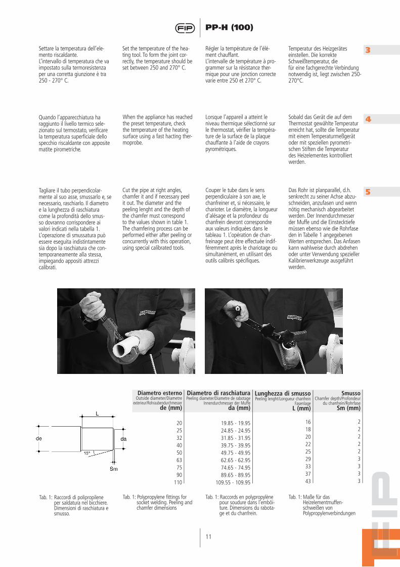
Tagliare il tubo perpendicolar-mente al suo asse, smussarlo e, se necessario, raschiarlo. Il diametro e la lunghezza di raschiatura come la profondità dello smus-so dovranno corrispondere ai valori indicati nella tabella 1. L’operazione di smussatura può essere eseguita indistintamente sia dopo la raschiatura che con-temporaneamente alla stessa, impiegando appositi attrezzi calibrati.
Cut the pipe at right angles, chamfer it and if necessary peel it out. The diameter and the peeling lenght and the depth of the chamfer must correspond to the values shown in table 1. The chamfering process can be performed either after peeling or concurrently with this operation, using special calibrated tools.
Couper le tube dans le sens perpendiculaire à son axe, le chanfreiner et, si nécessaire, le charioter. Le diamètre, la longueur d’alésage et la profondeur du chanfrein devront correspondre aux valeurs indiquées dans le tableau 1. L’opération de chan-freinage peut être effectuée indif-féremment après le chariotage ou simultanément, en utilisant des outils calibrés spécifiques.
Das Rohr ist planparallel, d.h. senkrecht zu seiner Achse abzu-schneiden, anzufasen und wenn nötig mechanisch abgearbeitet werden. Der Innendurchmesser der Muffe und die Einstecktiefe müssen ebenso wie die Rohrfase den in Tabelle 1 angegebenen Werten entsprechen. Das Anfasen kann wahlweise durch abdrehen oder unter Verwendung spezieller Kalibrierwerkzeuge ausgeführt werden.
3
4
5
SmussoChamfer depth/Profondeur
du chanfrein/RohrfaseSm (mm)
222223333
Lunghezza di smussoPeeling lenght/Longueur chanfrein
FasenlageL (mm)
161820222529333743
Diametro di raschiaturaPeeling diameter/Diametre de rabotage
Innendurchmesser der Muffeda (mm)
19.85 - 19.9524.85 - 24.9531.85 - 31.9539.75 - 39.9549.75 - 49.9562.65 - 62.9574.65 - 74.9589.65 - 89.95
109.55 - 109.95
Diametro esternoOutside diameter/Diametre
exterieur/Rohraubendurchmesserde (mm)
2025324050637590
110
Tab. 1: Raccordi di polipropilene per saldatura nel bicchiere. Dimensioni di raschiatura e smusso.
Tab. 1: Polypropylene fittings for socket welding. Peeling and chamfer dimensions
Tab. 1: Raccords en polypropylène pour soudure dans l’embôi-ture. Dimensions du rabota-ge et du chanfrein.
Tab. 1: Maße für das Heizelementmuffen-schweißen von Polypropylenverbindungen
12
PP-H (100)
12
PP-H (100)
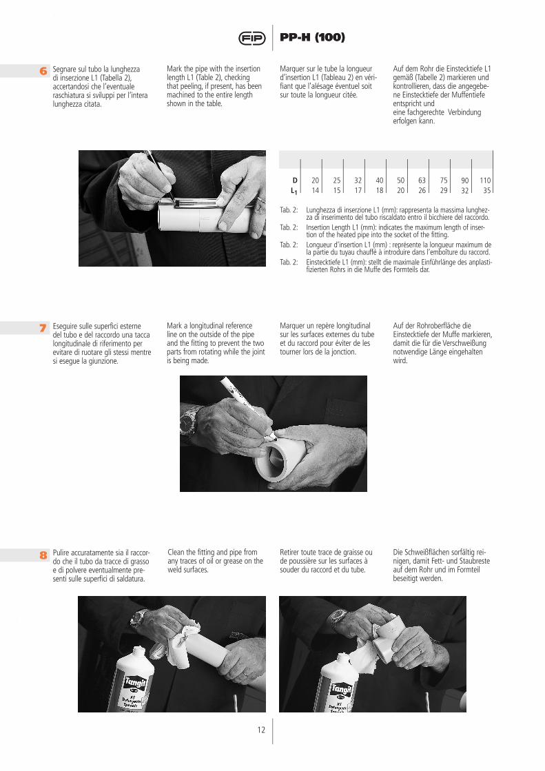
Segnare sul tubo la lunghezza di inserzione L1 (Tabella 2), accertandosi che l’eventuale raschiatura si sviluppi per l’intera lunghezza citata.
Mark the pipe with the insertion length L1 (Table 2), checking that peeling, if present, has been machined to the entire length shown in the table.
Marquer sur le tube la longueur d’insertion L1 (Tableau 2) en véri-fiant que l’alésage éventuel soit sur toute la longueur citée.
Auf dem Rohr die Einstecktiefe L1 gemäß (Tabelle 2) markieren und kontrollieren, dass die angegebe-ne Einstecktiefe der Muffentiefe entspricht und eine fachgerechte Verbindung erfolgen kann.
Eseguire sulle superfici esterne del tubo e del raccordo una tacca longitudinale di riferimento per evitare di ruotare gli stessi mentre si esegue la giunzione.
Mark a longitudinal reference line on the outside of the pipe and the fitting to prevent the two parts from rotating while the joint is being made.
Marquer un repère longitudinal sur les surfaces externes du tube et du raccord pour éviter de les tourner lors de la jonction.
Auf der Rohroberfläche die Einstecktiefe der Muffe markieren, damit die für die Verschweißung notwendige Länge eingehalten wird.
Pulire accuratamente sia il raccor-do che il tubo da tracce di grasso e di polvere eventualmente pre-senti sulle superfici di saldatura.
Clean the fitting and pipe from any traces of oil or grease on the weld surfaces.
Retirer toute trace de graisse ou de poussière sur les surfaces à souder du raccord et du tube.
Die Schweißflächen sorfältig rei-nigen, damit Fett- und Staubreste auf dem Rohr und im Formteil beseitigt werden.
6
7
8
11035
9032
7529
DL1
2014
2515
3217
4018
5020
6326
Tab. 2: Lunghezza di inserzione L1 (mm): rappresenta la massima lunghez-za di inserimento del tubo riscaldato entro il bicchiere del raccordo.
Tab. 2: Insertion Length L1 (mm): indicates the maximum length of inser-tion of the heated pipe into the socket of the fitting.
Tab. 2: Longueur d’insertion L1 (mm) : représente la longueur maximum de la partie du tuyau chauffé à introduire dans l’emboîture du raccord.
Tab. 2: Einstecktiefe L1 (mm): stellt die maximale Einführlänge des anplasti-fizierten Rohrs in die Muffe des Formteils dar.
12
PP-H (100)
13
PP-H (100)
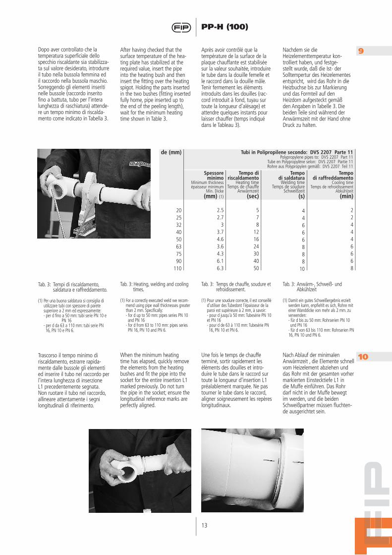
Dopo aver controllato che la temperatura superficiale dello specchio riscaldante sia stabilizza-ta sul valore desiderato, introdurre il tubo nella bussola femmina ed il raccordo nella bussola maschio. Sorreggendo gli elementi inseriti nelle bussole (raccordo inserito fino a battuta, tubo per l’intera lunghezza di raschiatura) attende-re un tempo minimo di riscalda-mento come indicato in Tabella 3.
After having checked that the surface temperature of the hea-ting plate has stabilized at the required value, insert the pipe into the heating bush and then insert the fitting over the heating spigot. Holding the parts inserted in the two bushes (fitting inserted fully home, pipe inserted up to the end of the peeling length), wait for the minimum heating time shown in Table 3.
Après avoir contrôlé que la température de la surface de la plaque chauffante est stabilisée sur la valeur souhaitée, introduire le tube dans la douille femelle et le raccord dans la douille mâle. Tenir fermement les éléments introduits dans les douilles (rac-cord introduit à fond, tuyau sur toute la longueur d’alésage) et attendre quelques instants pour laisser chauffer (temps indiqué dans le Tableau 3).
Nachdem sie die Heizelementtemperatur kon-trolliert haben, und festge-stellt wurde, daß die Ist- der Solltempertur des Heizelementes entspricht, wird das Rohr in die Heizbuchse bis zur Markierung und das Formteil auf den Heizdorn aufgesteckt gemäß den Angaben in Tabelle 3. Die beiden Teile sind während der Anwärmszeit mit der Hand ohne Druck zu halten.
Trascorso il tempo minimo di riscaldamento, estrarre rapida-mente dalle bussole gli elementi ed inserire il tubo nel raccordo per l’intera lunghezza di inserzione L1 precedentemente segnata. Non ruotare il tubo nel raccordo, allineare attentamente i segni longitudinali di riferimento.
When the minimum heating time has elapsed, quickly remove the elements from the heating bushes and fit the pipe into the socket for the entire insertion L1 marked previously. Do not turn the pipe in the socket; ensure the longitudinal reference marks are perfectly aligned.
Une fois le temps de chauffe terminé, sortir rapidement les éléments des douilles et intro-duire le tube dans le raccord sur toute la longueur d’insertion L1 préalablement marquée. Ne pas tourner le tube dans le raccord, aligner soigneusement les repères longitudinaux.
Nach Ablauf der minimalen Anwärmzeit , die Elemente schnell vom Heizelement abziehen und das Rohr mit der gesamten vorher markierten Einstecktiefe L1 in die Muffe einführen. Das Rohr darf nicht in der Muffe bewegt im werden, und die beiden Schweißpartner müssen fluchten-de ausgerichtet sein.
Tab. 3: Tempi di riscaldamento, saldatura e raffreddamento.
(1) Per una buona saldatura si consiglia di utilizzare tubi con spessore di parete superiore a 2 mm ed espressamente:
- per d fino a 50 mm: tubi serie PN 10 e PN 16
- per d da 63 a 110 mm: tubi serie PN 16, PN 10 e PN 6.
Tab. 3: Heating, welding and cooling times.
(1) For a correctly executed weld we recom-mend using pipe wall thicknesses greater than 2 mm. Specifically:
- for d up to 50 mm: pipes series PN 10 and PN 16
- for d from 63 to 110 mm: pipes series PN 16, PN 10 and PN 6.
Tab. 3: Temps de chauffe, soudure et refroidissement.
(1) Pour une soudure correcte, il est conseillé d’utiliser des Tubedont l’épaisseur de la paroi est supérieure à 2 mm, à savoir:
- pour d jusqu’à 50 mm: Tubesérie PN 10 et PN 16
- pour d de 63 à 110 mm: Tubesérie PN 16, PN 10 et PN 6.
Tab. 3: Anwärm-, Schweiß- und Abkühlzeit
(1) Damit ein gutes Schweißergebnis erzielt werden kann, enpfiehlt es sich, Rohre mit einer Wanddicke von mehr als 2 mm. zu verwenden:
- für d bis zu 50 mm: Rohrserien PN 10 und PN 16
- für d von 63 bis 110 mm: Rohrserien PN 16, PN 10 und PN 6.
9
10
Tempodi raffreddamento
Cooling timeTemps de refroidissement
Abkühlzeit(min)
224446668
Tempodi saldatura
Welding timeTemps de soudure
Schweißzeit(s)
44666888
10
Spessore minimo
Minimum thicknessépaisseur minimum
Min. Dicke(mm) (1)
2.52.7
33.74.63.64.36.16.3
de (mm)
2025324050637590
110
Tempo di riscaldamento
Heating timeTemps de chauffe
Anwärmzeit(sec)
578
121624304050
Tubi in Polipropilene secondo: DVS 2207 Parte 11Polypropylene pipes to: DVS 2207 Part 11
Tube en Polypropylène selon: DVS 2207 Partie 11Rohre aus Polypropylen gemäß: DVS 2207 Teil 11
14
PP-H (100)
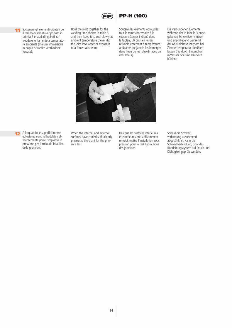
Sostenere gli elementi giuntati per il tempo di saldatura riportato in tabella 3 e lasciarli, quindi, raf-freddare lentamente a temperatu-ra ambiente (mai per immersione in acqua o tramite ventilazione forzata).
Hold the joint together for the welding time shown in table 3 and then leave it to cool slowly at ambient temperature (never dip the joint into water or expose it to a forced airstream).
Soutenir les éléments accouplés tout le temps nécessaire à la soudure (temps indiqué dans le tableau 3) puis les laisser refroidir lentement à température ambiante (ne jamais les immerger dans l’eau ou les refroidir avec un ventilateur).
Die verbundenen Elemente während der in Tabelle 3 ange-gebenen Schweißzeit stützen und anschließend während der Abkühlphase langsam bei Zimmer-temperatur abkühlen lassen (nie durch Eintauchen in Wasser oder mit Druckluft kühlen).
Allorquando le superfici interne ed esterne sono raffreddate suf-ficentemente porre l’impianto in pressione per il collaudo idraulico delle giunzioni.
When the internal and external surfaces have cooled suffiuciently, pressurize the plant for the pres-sure test.
Dès que les surfaces intérieures et extérieures ont suffisamment refroidi, mettre l’installation sous pression pour le test hydraulique des jonctions.
Sobald die Schweiß-verbindung ausreichend abgekühlt ist, kann die Schweißverbindung, bzw. das Rohrleitungssystem auf Druck und Dichtigkeit geprüft werden.
11
12