Embed Size (px)
Citation preview

AVR200: Multiply and Divide Routines
Features • 8 and 16-bit Implementations • Signed & Unsigned Routines • Speed & Code Size Optimized Routines • Runable Example Programs • Speed is Comparable with HW Multiplicators/Dividers • Example: 8 x 8 Mul in 2.8 µs, 16 x 16 Mul in 8.7 µs (12 MHz) • Extremely Compact Code
1 Introduction This application note lists subroutines for multiplication and division of 8- and 16-bit signed and unsigned numbers. A listing of all implementations with key performance specifications is given in Table 1-1.
Table 1-1. Performance Figures Summary
Application Code Size (Words)
Execution Time (Cycles)
8 x 8 = 16 bit unsigned (Code Optimized) 9 58
8 x 8 = 16 bit unsigned (Speed Optimized) 34 34
8 x 8 = 16 bit signed (Code Optimized) 10 73
16 x 16 = 32 bit unsigned (Code Optimized) 14 153
16 x 16 = 32 bit unsigned (Speed Optimized) 105 105
16 x 16 = 32 bit signed (Code Optimized) 16 218
8 / 8 = 8 + 8 bit unsigned (Code Optimized) 14 97
8 / 8 = 8 + 8 bit unsigned (Speed Optimized) 66 58
8 / 8 = 8 + 8 bit signed (Code Optimized) 22 103
16 / 16 = 16 + 16 bit unsigned (Code Optimized) 19 243
16 / 16 = 16 + 16 bit unsigned (Speed Optimized) 196 173
16 / 16 = 16 + 16 bit signed (Code Optimized) 39 255 The application note listing consists of two files:
• “avr200.asm”: Code size optimized multiplied and divide routines. • “avr200b.asm”: Speed optimized multiply and divide routines.
8-bit Microcontrollers Application Note
Rev. 0936C-AVR-05/06

2 AVR200 0936C-AVR-05/06
2 8 x 8 = 16 Unsigned Multiplication – “mpy8u” Both program files contain a routine called “mpy8u” which performs unsigned 8-bit multiplication. Both implementations are based on the same algorithm. The code size optimized implementation, however, uses looped code whereas the speed optimized code is a straight-line code implementation. Figure 2-1 shows the flow chart for the code size optimized version.
2.1 Algorithm Description The algorithm for the Code Size optimized version is as follows:
1. Clear result High byte. 2. Load Loop counter with eight. 3. Shift right multiplier 4. If carry (previous bit 0 of multiplier) set, add multiplicand to result High byte. 5. Shift right result High byte into result Low byte/multiplier. 6. Shift right result Low byte/multiplier. 7. Decrement Loop counter. 8. If Loop counter not zero, go to Step 4. Figure 2-1. “mpy8u” Flow Chart (Code Size Optimized Implementation)
DECREMENT LOOP COUNTER
MPY8U
CLEAR RESULT HIGH BYTE
LOOP COUNTER ← 8
SHIFT MULTIPLIERRIGHT
SHIFT RIGHT RESULTHIGH BYTE
SHIFT RIGHT RESULT LOW BYTE AND MULTIPLIER
CARRY SET?
LOOP COUNTER = 0?
RETURN
Y
N
N
ADD MULTIPLICANDTO RESULT HIGH BYTE
Y
AVR200
3
0936C-AVR-05/06
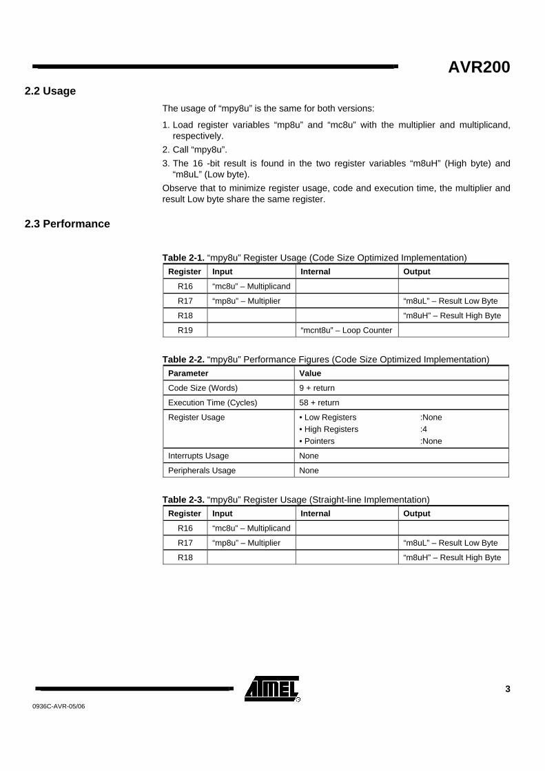
2.2 Usage The usage of “mpy8u” is the same for both versions:
1. Load register variables “mp8u” and “mc8u” with the multiplier and multiplicand, respectively.
2. Call “mpy8u”. 3. The 16 -bit result is found in the two register variables “m8uH” (High byte) and
“m8uL” (Low byte). Observe that to minimize register usage, code and execution time, the multiplier and result Low byte share the same register.
2.3 Performance
Table 2-1. “mpy8u” Register Usage (Code Size Optimized Implementation) Register Input Internal Output
R16 “mc8u” – Multiplicand
R17 “mp8u” – Multiplier “m8uL” – Result Low Byte
R18 “m8uH” – Result High Byte
R19 “mcnt8u” – Loop Counter
Table 2-2. “mpy8u” Performance Figures (Code Size Optimized Implementation) Parameter Value
Code Size (Words) 9 + return
Execution Time (Cycles) 58 + return
Register Usage • Low Registers • High Registers • Pointers
:None :4 :None
Interrupts Usage None
Peripherals Usage None
Table 2-3. “mpy8u” Register Usage (Straight-line Implementation) Register Input Internal Output
R16 “mc8u” – Multiplicand
R17 “mp8u” – Multiplier “m8uL” – Result Low Byte
R18 “m8uH” – Result High Byte

4 AVR200 0936C-AVR-05/06
Table 2-4. “mpy8u” Performance Figures (Straight-line Implementation) Parameter Value
Code Size (Words) 34 + return
Execution Time (Cycles) 34 + return
Register Usage • Low Registers • High Registers • Pointers
:None :3 :None
Interrupts Usage None
Peripherals Usage None
3 8 x 8 = 16 Signed Multiplication – “mpy8s” This subroutine, which is found in “avr200.asm” implements signed 8 x 8 multiplication. Negative numbers are represented as 2’s complement numbers. The application is an implementation of Booth's algorithm. The algorithm provides both small and fast code. However, it has one limitation that the user should bear in mind; If all 16 bits of the result is needed, the algorithm fails when used with the most negative number (-128) as the multiplicand.
3.1 Algorithm Description The algorithm for signed 8 x 8 multiplication is as follows:
1. Clear result High byte and carry. 2. Load Loop counter with eight. 3. If carry (previous bit 0 of multiplier) set, add multiplicand to result High byte. 4. If current bit 0 of multiplier set, subtract multiplicand from result High byte. 5. Shift right result High byte into result Low byte/multiplier. 6. Shift right result Low byte/multiplier. 7. Decrement Loop counter. 8. If Loop counter not zero, go to Step 3.

AVR200
5
0936C-AVR-05/06
Figure 3-1. “mpy8s” Flow Chart
DECREMENT LOOP COUNTER
MPY8S
CLEAR RESULT HIGH BYTE AND CARRY
LOOP COUNTER ← 8
SHIFT RIGHT RESULTHIGH BYTE
SHIFT RIGHT RESULT LOW BYTE AND MULTIPLIER
CARRY = 1?
BIT 0 OF MULTIPLIER
SET?
LOOP COUNTER = 0?
RETURN
Y
N
N
N
ADD MULTIPLICANDTO RESULT HIGH BYTE
SUBTRACT MULTIPLICANDFROM RESULT HIGH BYTE
Y
Y
3.2 Usage The usage of “mpy8s” is as follows:
1. Load register variables “mp8s” and “mc8s” with the multiplier and multiplicand, respectively.
2. Call “mpy8s”. 3. The 16 -bit result is found in the two register variables “m8sH” (High byte) and
“m8sL” (Low byte). Observe that to minimize register usage, code and execution time, the multiplier and result Low byte share the same register.
3.3 Performance Table 3-1. “mpy8s” Register Usage
Register Input Internal Output
R16 “mc8s” – Multiplicand
R17 “mp8s” – Multiplier “m8sL” – Result Low Byte
R18 “m8sH” – Result High Byte
R19 “mcnt8s” – Loop Counter

6 AVR200 0936C-AVR-05/06
Table 3-2. “mpy8s” Performance Figures Parameter Value
Code Size (Words) 10 + return
Execution Time (Cycles) 73 + return
Register Usage • Low Registers • High Registers • Pointers
:None :4 :None
Interrupts Usage None
Peripherals Usage None
4 16 x 16 = 32 Unsigned Multiplication – “mpy16u” Both program files contain a routine called “mpy16u” which performs unsigned 16-bit multiplication. Both implementations are based on the same algorithm. The code size optimized implementation, however, uses looped code whereas the speed optimized code is a straight-line code implementation. Figure 4-1 shows the flow chart for the Code Size optimized (looped) version.
4.1 Algorithm Description The algorithm for the Code Size optimized version is as follows:
1. Clear result High word (Bytes 2 and 3) 2. Load Loop counter with 16. 3. Shift multiplier right 4. If carry (previous bit 0 of multiplier Low byte) set, add multiplicand to result High
word. 5. Shift right result High word into result Low word/multiplier. 6. Shift right Low word/multiplier. 7. Decrement Loop counter. 8. If Loop counter not zero, go to Step 4.

AVR200
7
0936C-AVR-05/06
Figure 4-1. “mpy16u” Flow Chart (Code Size Optimized Implementation)
DECREMENT LOOP COUNTER
MPY16U
CLEAR RESULT HIGH WORD
LOOP COUNTER ←$16
SHIFT MULTIPLIERRIGHT
SHIFT RIGHT RESULTHIGH WORD
SHIFT RIGHT RESULT LOWWORD AND MULTIPLIER
CARRY SET?
LOOP COUNTER = 0?
RETURN
Y
N
N
ADD MULTIPLICANDTO RESULT HIGH WORD
Y
4.2 Usage The usage of “mpy16u” is the same for both versions:
1. Load register variables “mp16uL”/”mp16uH” with multiplier Low and High byte, respectively.
2. Load register variables “mc16uH”/”mc16uH” with multiplicand Low and High byte, respectively.
3. Call “mpy16u”. 4. The 32-bit result is found in the 4-byte register variable
“m16u3:m16u2:m16u1:m16u0”. Observe that to minimize register usage, code and execution time, the multiplier and result Low word share the same registers.

8 AVR200 0936C-AVR-05/06
4.3 Performance Table 4-1. “mpy16u” Register Usage (Code Size Optimized Implementation)
Register Input Internal Output
R16 “mc16uL” – Multiplicand Low Byte
R17 “mc16uH” – Multiplicand High Byte
R18 “mp16uL” – Multiplier Low Byte “m16u0” – Result Byte 0
R19 “mp16uH” – Multiplier High Byte “m16u1” – Result Byte 1
R20 “m16u2” – Result Byte 2
R21 “m16u2” – Result Byte 2
R22 “mcnt16u” – Loop Counter
Table 4-2. “mpy16u” Performance Figures (Code Size Optimized Implementation) Parameter Value
Code Size (Words) 14 + return
Execution Time (Cycles) 153 + return
Register Usage • Low Registers • High Registers • Pointers
:None :7 :None
Interrupts Usage None
Peripherals Usage None
Table 4-3. “mpy16u” Register Usage (Straight-line Implementation) Register Input Internal Output
R16 “mc16uL” – Multiplicand Low Byte
R17 “mc16uH” – Multiplicand High Byte
R18 “mp16uL” – Multiplier Low Byte “m16u0” – Result Byte 0
R19 “mp16uH” – Multiplier High Byte “m16u1” – Result Byte 1
R20 “m16u2” – Result Byte 2
R21 “m16u2” – Result Byte 2
Table 4-4. “mpy16u” Performance Figures (Straight-line Implementation) Parameter Value
Code Size (Words) 105 + return
Execution Time (Cycles) 105 + return
Register Usage • Low Registers • High Registers • Pointers
:None :6 :None
Interrupts Usage None
Peripherals Usage None

AVR200
9
0936C-AVR-05/06
5 16 x 16 = 32 Signed Multiplication - “mpy16s” This subroutine, which is found in “avr200.asm” implements signed 16 x 16 multiplication. Negative numbers are represented as 2’s complement numbers. The application is an implementation of Booth’s algorithm. The algorithm provides both small and fast code. However, it has one limitation that the user should bear in mind; If all 32 bits of the result is needed, the algorithm fails when used with the most negative number (-32768) as the multiplicand.
5.1 Algorithm Description The algorithm for signed 16 x 16 multiplication is as follows:
1. Clear result High word (Bytes 2&3) and carry. 2. Load Loop counter with 16. 3. If carry (previous bit 0 of multiplier Low byte) set, add multiplicand to result High
word. 4. If current bit 0 of multiplier Low byte set, subtract multiplicand from result High
word. 5. Shift right result High word into result Low word/multiplier. 6. Shift right Low word/multiplier. 7. Decrement Loop counter. 8. If Loop counter not zero, go to Step 3. Figure 5-1. “mpy16s” Flow Chart
DECREMENT LOOP COUNTER
MPY16S
CLEAR RESULT HIGH WORD AND CARRY
LOOP COUNTER ← $8
SHIFT RIGHT RESULTHIGH WORD
SHIFT RIGHT RESULT LOWWORD AND MULTIPLIER
CARRY = 1?
BIT 0 OF MULTIPLIER LOW
BYTE SET?
LOOP COUNTER = 0?
RETURN
Y
N
N
N
ADD MULTIPLICANDTO RESULT HIGH WORD
SUBTRACT MULTIPLICANDFROM RESULT HIGH WORD
Y
Y

10 AVR200 0936C-AVR-05/06
5.2 Usage The usage of “mpy16s” is as follows:
1. Load register variables “mp16sL”/”mp16sH” with multiplier Low and High byte, respectively.
2. Load register variables “mc16sH”/”mc16sH” with multiplicand Low and High byte, respectively.
3. Call “mpy16s”. 4. The 32-bit result is found in the 4-byte register variable
“m16s3:m16s2:m16s1:m16s0”. Observe that to minimize register usage, code and execution time, the multiplier and result Low byte share the same register.
5.3 Performance Table 5-1. “mpy16s” Register Usage
Register Input Internal Output
R16 “mc16sL” – Multiplicand Low Byte
R17 “mc16sH” – Multiplicand High Byte
R18 “mp16sL” – Multiplier Low Byte “m16s0” – Result Byte 0
R19 “mp16sH” – Multiplier High Byte “m16s1” – Result Byte 1
R20 “m16s2” – Result Byte 2
R21 “m16s2” – Result Byte 2
R22 “mcnt16s” – Loop Counter
Table 5-2. “mpy16s” Performance Figures Parameter Value
Code Size (Words) 16 + return
Execution Time (Cycles) 218 + return
Register Usage • Low Registers • High Registers • Pointers
:None :7 :None
Interrupts Usage None
Peripherals Usage None

AVR200
11
0936C-AVR-05/06
6 8 / 8 = 8 + 8 Unsigned Division – “div8u” Both program files contain a routine called “div8u” which performs unsigned 8-bit division. Both implementations are based on the same algorithm. The code size optimized implementation, however, uses looped code, whereas the speed optimized code is a straight-line code implementation. Figure 6-1 shows the flow chart for the code size optimized version.
6.1 Algorithm Description The algorithm for unsigned 8/8 division (Code Size optimized code) is as follows:
1. Clear remainder and carry. 2. Load Loop counter with nine. 3. Shift left dividend into carry. 4. Decrement Loop counter. 5. If Loop counter = 0, return. 6. Shift left carry (from dividend/result) into remainder 7. Subtract divisor from remainder. 8. If result negative, add back divisor, clear carry and goto Step 3. 9. Set carry and go to Step 3.
Figure 6-1. “div8u” Flow Chart (Code Size Optimized Implementation)
CLEAR CARRY
SET CARRY
DIV8U
CLEAR REMAINDERAND CARRY
LOOP COUNTER ← $9
DECREMENT LOOPCOUNTER
SHIFT LEFT DIVIDEND
REMAINDER ←REMAINDER + DIVISOR
LOOP COUNTER = 0?
RESULT NEGATIVE?
RETURN
Y
SHIFT LEFT REMAINDER
REMAINDER ← REMAINDER DIVISOR
N
Y
N

12 AVR200 0936C-AVR-05/06
6.2 Usage The usage of “div8u” is the same for both implementations and is described in the following procedure:
1. Load register variable “dd8u” with the dividend (the number to be divided). 2. Load register variable “dv8u” with the divisor (the dividing number). 3. Call “div8u”. 4. The result is found in “dres8u” and the remainder in “drem8u”.
6.3 Performance Table 6-1. “div8u” Register Usage (Code Size Optimized Version)
Register Input Internal Output
R15 “drem8u” – Remainder
R16 “dd8u” – Dividend “dres8u” – Result
R17 “dv8u” – Divisor”
R18 “dcnt8u” – Loop Counter
Table 6-2. “div8u” Performance Figures (Code Size Optimized Version) Parameter Value
Code Size (Words) 14
Execution Time (Cycles) 97
Register Usage • Low Registers • High Registers • Pointers
:1 :3 :None
Interrupts Usage None
Peripherals Usage None
Table 6-3. “div8u” Register Usage (Speed Optimized Version) Register Input Internal Output
R15 “drem8u” – Remainder
R16 “dd8u” – Dividend “dres8u” – Result
R17 “dv8u” – Divisor”
Table 6-4. “div8u” Performance Figures (Speed Optimized Version) Parameter Value
Code Size (Words) 66
Execution Time (Cycles) 58
Register Usage • Low Registers • High Registers • Pointers
:1 :2 :None
Interrupts Usage None
Peripherals Usage None

AVR200
13
0936C-AVR-05/06
7 8 / 8 = 8 + 8 Signed Division – “div8s” The subroutine “mpy8s” implements signed 8-bit division. The implementation is Code Size optimized. If negative, the input values shall be represented on 2’s complement's form.
7.1 Algorithm Description The algorithm for signed 8/8 division is as follows:
1. XOR dividend and divisor and store in a Sign Register. 2. If MSB of dividend set, negate dividend. 3. If MSB if divisor set, negate dividend. 4. Clear remainder and carry. 5. Load Loop counter with nine. 6. Shift left dividend into carry. 7. Decrement Loop counter. 8. If Loop counter ¼ 0, goto step 11. 9. If MSB of Sign Register set, negate result. 10. Return 11. Shift left carry (from dividend/result) into remainder. 12. Subtract divisor from remainder. 13. If result negative, add back divisor, clear carry and go to Step 6. 14. Set carry and go to Step 6.

14 AVR200 0936C-AVR-05/06
Figure 7-1. “div8s” Flow Chart
DECREMENT LOOP COUNTER
NEGATE RESULT
DIV8S
SIGN REGISTER ← DIVIDEND XOR DIVISOR
LOOP COUNTER ← 9
SHIFT LEFT DIVIDEND
SET CARRY
REMAINDER ←REMAINDER + DIVISOR
CLEAR CARRY
MSB OFDIVIDEND SET?
MSB OFDIVISOR SET?
LOOP COUNTER = 0?
REMAINDER ←REMAINDER DIVISOR
SHIFT LEFT REMAINDER
RESULT NEGATIVE?
N
Y MSB OF SIGNREGISTER SET?
RETURN
N
Y
Y
Y
NEGATE DIVISOR
N
NEGATE DIVIDEND
N
N
Y
7.2 Usage The usage of “div8s” follows the procedure below:
1. Load register variable “dd8s” with the dividend (the number to be divided). 2. Load register variable “dv8s” with the divisor (the dividing number). 3. Call “div8s”. 4. The result is found in “dres8s” and the remainder in “drem8s”.

AVR200
15
0936C-AVR-05/06
7.3 Performance Table 7-1. “div8u” Register Usage
Register Input Internal Output
R14 “d8s” – Sign Register
R15 “drem8s” – Remainder
R16 “dd8s” – Dividend “dres8s” – Result
R17 “dv8s” – Divisor”
R18 “dcnt8s” – Loop Counter
Table 7-2. “div8s” Performance Figures (Code Size Optimized Version) Parameter Value
Code Size (Words) 22
Execution Time (Cycles) 103
Register Usage • Low Registers • High Registers • Pointers
:2 :3 :None
Interrupts Usage None
Peripherals Usage None
8 16 / 16 = 16 + 16 Unsigned Division – “div16u” Both program files contain a routine called “div16u” which performs unsigned 16-bit division
Both implementations are based on the same algorithm. The code size optimized implementation, however, uses looped code whereas the speed optimized code is a straight-line code implementation. Figure 8-1 shows the flow chart for the code size optimized version.
8.1 Algorithm Description The algorithm for unsigned 16 / 16 division (Code Size optimized code) is as follows:
1. Clear remainder and carry. 2. Load Loop counter with 17. 3. Shift left dividend into carry 4. Decrement Loop counter. 5. If Loop counter = 0, return. 6. Shift left carry (from dividend/result) into remainder 7. Subtract divisor from remainder. 8. If result negative, add back divisor, clear carry and go to Step 3. 9. Set carry and go to Step 3.

16 AVR200 0936C-AVR-05/06
Figure 8-1. “div16u” Flow Chart (Code Size Optimized Implementation) DIV16U
CLEAR REMAINDER AND CARRY
LOOP COUNTER ← 17
SHIFT LEFT DIVIDEND
DECREMENT LOOPCOUNTER
SET CARRY
REMAINDER ←REMAINDER + DIVISOR
CLEAR CARRY
LOOP COUNTER = 0?
Y
RETURN
REMAINDER ←REMAINDER DIVISOR
SHIFT LEFT REMAINDER
RESULT NEGATIVE?
N
N
Y
8.2 Usage The usage of “div16u” is the same for both implementations and is described in the following procedure:
1. Load the 16-bit register variable “dd16uH:dd16uL” with the dividend (the number to be divided).
2. Load the 16-bit register variable “dv16uH:dv16uL” with the divisor (the dividing number).
3. Call “div16u”. 4. The result is found in “dres16u” and the remainder in “drem16u”.

AVR200
17
0936C-AVR-05/06
8.3 Performance Table 8-1. “div16u” Register Usage (Code Size Optimized Version)
Register Input Internal Output
R14 “drem16uL” – Remainder Low Byte
R15 “drem16uH – Remainder High Byte
R16 “dd16uL” – Dividend Low Byte
“dres16uL” – Result Low Byte
R17 “dd16uH” – Dividend High Byte
“dres16uH” – Result High Byte
R18 “dv16uL” – Divisor Low Byte
“drem16uL” – Remainder Low Byte
R19 “dv16uH” – Divisor High Byte
R20 “dcnt16u” – Loop Counter
Table 8-2. “div16u” Performance Figures (Code Size Optimized Version) Parameter Value
Code Size (Words) 19
Execution Time (Cycles) 243
Register Usage • Low Registers • High Registers • Pointers
:2 :5 :None
Interrupts Usage None
Peripherals Usage None
Table 8-3. “div16u” Register Usage (Speed Optimized Version) Register Input Internal Output
R14 “drem16uL” – Remainder Low Byte
R15 “drem16uH – Remainder High Byte
R16 “dd16uL” – Dividend Low Byte
“dres16uL” – Result Low Byte
R17 “dd16uH” – Dividend High Byte
“dres16uH” – Result High Byte
R18 “dv16uL” – Divisor Low Byte
R19 “dv16uH” – Divisor High Byte

18 AVR200 0936C-AVR-05/06
Table 8-4. “div16u” Performance Figures (Speed Optimized Version) Parameter Value
Code Size (Words) 196 + return
Execution Time (Cycles) 173
Register Usage • Low Registers • High Registers • Pointers
:2 :4 :None
Interrupts Usage None
Peripherals Usage None
9 16 / 16 = 16 + 16 Signed Division – “div16s” The subroutine “mpy16s” implements signed 16-bit division. The implementation is Code Size optimized. If negative, the input values shall be represented on 2’s complement’s form.
9.1 Algorithm Description The algorithm for signed 16 / 16 division is as follows:
1. XOR dividend and divisor High bytes and store in a Sign Register. 2. If MSB of dividend High byte set, negate dividend. 3. If MSB if divisor set High byte, negate dividend. 4. Clear remainder and carry. 5. Load Loop counter with 17. 6. Shift left dividend into carry. 7. Decrement Loop counter. 8. If Loop counter ¼ 0, go to step 11. 9. If MSB of Sign register set, negate result. 10. Return 11. Shift left carry (from dividend/result) into remainder 12. Subtract divisor from remainder. 13. If result negative, add back divisor, clear carry and go to Step 6. 14. Set carry and go to Step 6.

AVR200
19
0936C-AVR-05/06
Figure 9-1. “div16s” Flow Chart
DECREMENT LOOP COUNTER
NEGATE RESULT
DIV16S
SIGN REGISTER ←DIVIDENDH XOR DIVISORH
LOOP COUNTER ← 17
SHIFT LEFT DIVIDEND
SET CARRY
REMAINDER ←REMAINDER + DIVISOR
CLEAR CARRY
MSB OFDIVIDEND SET?
MSB OFDIVISOR SET?
LOOP COUNTER = 0?
REMAINDER ←REMAINDER DIVISOR
SHIFT LEFT REMAINDER
RESULT NEGATIVE?
N
Y MSB OF SIGNREGISTER SET?
RETURN
N
Y
Y
Y
NEGATE DIVISOR
N
NEGATE DIVIDEND
N
N
Y
9.2 Usage The usage of “div16s” is described in the following procedure:
1. Load the 16-bit register variable “dd16sH:dd16sL” with the dividend (the number to be divided).
2. Load the 16-bit register variable “dv16sH:dv16sL” with the divisor (the dividing number).
3. Call “div16s”. 4. The result is found in “dres16s” and the remainder in “drem16s”.

20 AVR200 0936C-AVR-05/06
9.3 Performance Table 9-1. “div16s” Register Usage
Register Input Internal Output
R14 “drem16sL” – Remainder Low Byte
R15 “drem16sH – Remainder High Byte
R16 “dd16sL” – Dividend Low Byte
“dres16sL” – Result Low Byte
R17 “dd16sH” – Dividend High Byte
“dres16sH” – Result High Byte
R18 “dv16sL” – Divisor Low Byte
R19 “dv16sH” – Divisor High Byte
R20 “dcnt16s” – Loop Counter
Table 9-2. “div16s” Performance Figures Parameter Value
Code Size (Words) 39
Execution Time (Cycles) 255
Register Usage • Low Registers • High Registers • Pointers
:2 :5 :None
Interrupts Usage None
Peripherals Usage None

0936C-AVR-05/06
Disclaimer Atmel Corporation
2325 Orchard Parkway San Jose, CA 95131, USA Tel: 1(408) 441-0311 Fax: 1(408) 487-2600
Regional Headquarters Europe
Atmel Sarl Route des Arsenaux 41 Case Postale 80 CH-1705 Fribourg Switzerland Tel: (41) 26-426-5555 Fax: (41) 26-426-5500
Asia Room 1219 Chinachem Golden Plaza 77 Mody Road Tsimshatsui East Kowloon Hong Kong Tel: (852) 2721-9778 Fax: (852) 2722-1369
Japan 9F, Tonetsu Shinkawa Bldg. 1-24-8 Shinkawa Chuo-ku, Tokyo 104-0033 Japan Tel: (81) 3-3523-3551 Fax: (81) 3-3523-7581
Atmel Operations Memory
2325 Orchard Parkway San Jose, CA 95131, USA Tel: 1(408) 441-0311 Fax: 1(408) 436-4314
Microcontrollers 2325 Orchard Parkway San Jose, CA 95131, USA Tel: 1(408) 441-0311 Fax: 1(408) 436-4314 La Chantrerie BP 70602 44306 Nantes Cedex 3, France Tel: (33) 2-40-18-18-18 Fax: (33) 2-40-18-19-60
ASIC/ASSP/Smart Cards Zone Industrielle 13106 Rousset Cedex, France Tel: (33) 4-42-53-60-00 Fax: (33) 4-42-53-60-01 1150 East Cheyenne Mtn. Blvd. Colorado Springs, CO 80906, USA Tel: 1(719) 576-3300 Fax: 1(719) 540-1759 Scottish Enterprise Technology Park Maxwell Building East Kilbride G75 0QR, Scotland Tel: (44) 1355-803-000 Fax: (44) 1355-242-743
RF/Automotive Theresienstrasse 2 Postfach 3535 74025 Heilbronn, Germany Tel: (49) 71-31-67-0 Fax: (49) 71-31-67-2340 1150 East Cheyenne Mtn. Blvd. Colorado Springs, CO 80906, USA Tel: 1(719) 576-3300 Fax: 1(719) 540-1759
Biometrics/Imaging/Hi-Rel MPU/ High Speed Converters/RF Datacom
Avenue de Rochepleine BP 123 38521 Saint-Egreve Cedex, France Tel: (33) 4-76-58-30-00 Fax: (33) 4-76-58-34-80
Literature Requests
www.atmel.com/literature
Disclaimer: The information in this document is provided in connection with Atmel products. No license, express or implied, by estoppel or otherwise, to any intellectual property right is granted by this document or in connection with the sale of Atmel products. EXCEPT AS SET FORTH IN ATMEL’S TERMS AND CONDITIONS OF SALE LOCATED ON ATMEL’S WEB SITE, ATMEL ASSUMES NO LIABILITY WHATSOEVER AND DISCLAIMS ANY EXPRESS, IMPLIED OR STATUTORY WARRANTY RELATING TO ITS PRODUCTS INCLUDING, BUT NOT LIMITED TO, THE IMPLIED WARRANTY OF MERCHANTABILITY, FITNESS FOR A PARTICULAR PURPOSE, OR NON-INFRINGEMENT. IN NO EVENT SHALL ATMEL BE LIABLE FOR ANY DIRECT, INDIRECT, CONSEQUENTIAL, PUNITIVE, SPECIAL OR INCIDENTAL DAMAGES (INCLUDING, WITHOUT LIMITATION, DAMAGES FOR LOSS OF PROFITS, BUSINESS INTERRUPTION, OR LOSS OF INFORMATION) ARISING OUT OF THE USE OR INABILITY TO USE THIS DOCUMENT, EVEN IF ATMEL HAS BEEN ADVISED OF THE POSSIBILITY OF SUCH DAMAGES. Atmel makes no representations or warranties with respect to the accuracy or completeness of the contents of this document and reserves the right to make changes to specifications and product descriptions at any time without notice. Atmel does not make any commitment to update the information contained herein. Unless specifically provided otherwise, Atmel products are not suitable for, and shall not be used in, automotive applications. Atmel’s products are not intended, authorized, or warranted for use as components in applications intended to support or sustain life. © 2006 Atmel Corporation. All rights reserved. ATMEL®, logo and combinations thereof, Everywhere You Are®, AVR®, and others, are the registered trademarks or trademarks of Atmel Corporation or its subsidiaries. Other terms and product names may be trademarks of others.