Embed Size (px)
Citation preview

Stephen Shumaker, PE; Randall Hill, PE; Jason Yoshimura, PE;
Genevieve Osmena, PE; and Sami Kabar, PE
Stephen Shumaker
Genevieve Osmeña
Presented by

• Introduction to LA County Waterworks Districts and the Antelope Valley
• Water Supply Challenges for the Region
• Regional Planning Efforts
• Recycled Water Backbone Pipeline Project
• Approx. 180,000 customers
• Approx. 56,000 connections
Malibu
Val Verde
Kagel Cyn
Acton
Marina Del Rey
Downtown
Los Angeles
Antelope Valley (75 mi. north of downtown)

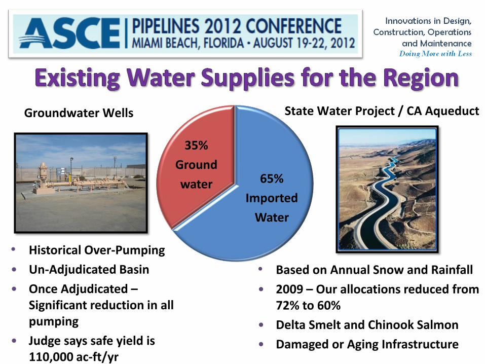
• Historical Over-Pumping
• Un-Adjudicated Basin
• Once Adjudicated – Significant reduction in all pumping
• Judge says safe yield is 110,000 ac-ft/yr
35%
Ground
water
65%
Imported
Water
Groundwater Wells
State Water Project / CA Aqueduct
• Based on Annual Snow and Rainfall
• 2009 – Our allocations reduced from 72% to 60%
• Delta Smelt and Chinook Salmon
• Damaged or Aging Infrastructure
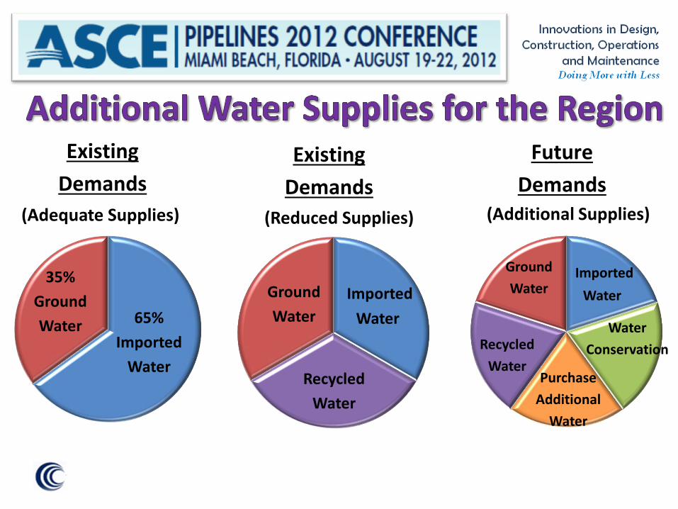
35%
Ground
Water
65%
Imported
Water
Existing
Demands
(Adequate Supplies)
Ground
Water
Imported
Water
Recycled
Water
Existing
Demands
(Reduced Supplies)
Future
Demands
Ground
Water
Imported
Water
Recycled
Water
Purchase
Additional
Water
Water
Conservation
(Additional Supplies)
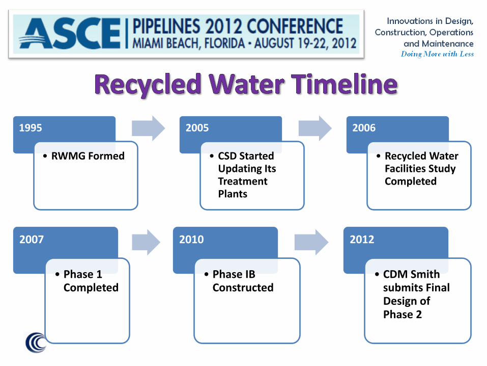
1995
• RWMG Formed
2005
• CSD Started Updating Its Treatment Plants
2006
• Recycled Water Facilities Study Completed
2007
• Phase 1 Completed
2010
• Phase IB Constructed
2012
• CDM Smith submits Final Design of Phase 2


• Low - 2,500 ft MSL at the future Palmdale Hybrid Power Plant site,
• High - 2,660 ft MSL near the water storage tank site.
• Uniform grades sloping southwest to northeast

• Pockets of residential,
commercial, and
industrial
development
• Rural desert

• Where practical, broad dirt shoulders along most of these roads were used.
• Congested with utilities.
• Most of the pipeline alignments are along existing roads.
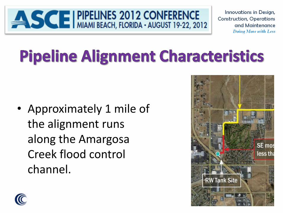
• Approximately 1 mile of the alignment runs along the Amargosa Creek flood control channel.
System Hydraulics

• Maximum initial design flow of 4,600 gpm
• Ultimate flow of 9,200 gpm
• At ultimate flow, velocity through a 24-inch pipe is 6.5 feet per second (ft/s), resulting in fairly high friction headlosses.
• Therefor the system was also analyzed based on a 30-inch pipeline.
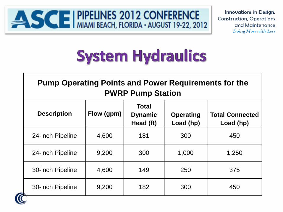
Pump Operating Points and Power Requirements for the
PWRP Pump Station
Description Flow (gpm) Total
Dynamic
Head (ft)
Operating
Load (hp)
Total Connected
Load (hp)
24-inch Pipeline 4,600 181 300 450
24-inch Pipeline 9,200 300 1,000 1,250
30-inch Pipeline 4,600 149 250 375
30-inch Pipeline 9,200 182 300 450

• 30-inch provides a slight reduction in
headlosses and power requirements for initial maximum, but large reduction in headlosses and power requirement for ultimate.
• However, there is uncertainty that capacity beyond the initial maximum capacity will be required.

• Given the expense of constructing a larger
pipeline (approximately $1,000,000 cost increase) to accommodate hydraulic conditions that may not occur, the District decided that a more economical 24-inch pipeline was appropriate for this project.

Pipe Material Selection

• The District’s preference for the project was
welded steel pipe.
• However, District staff asked CDM Smith to perform a brief evaluation of PVC, DIP, and HDPE pipeline materials for suitability for this project.
• The evaluations were general in nature and did not include life-cycle cost analyses.
• High strength, flexibility, and durability.
• Field welded joints typically used in western US require more labor than gasketted push-on typical of other pipe materials.
• Requires corrosion protection.
– Cement mortar lining and coating
– Cathodic protection

• High strength, durability, and impact
resistance.
• Requires corrosion protection.
– Polyethelyne encasement
– Cathodic protection in severe conditions
• Push-on gasket joints or mechanical joints
• Restrained push-on and MJ available

• Typically, less labor to install than welded
joint pipe particularly in utility-dense areas.
• Requires no corrosion protection.
• Push-on gasket joints
• After-market joint restraint for thrust
• Pressure classes exceeding 235 psi - sufficient for ultimate pressures
• Durable, ductile, and flexible material.
• Requires no corrosion protection.
• In sizes required for this project, available in pressure classes up to 200 psi, sufficient for maximum initial design pressures.
• Joint cooling time up to 90 s/in dia. = 36 minutes; for DR9 thickness > 2” and 100 summer heat, additional cooling time is likely

• Long strings of fused pipe can be lowered into
trench, ideal for long stretches with few crossing utilities, such as many areas along the proposed alignment
• Areas with many crossing utilities require special techniques and materials (electrofusion couplings)

• Any of these materials are suitable for the initial maximum flow condition of this project.
• District chose to use steel due to high strength, durability, and long service life.
• Also, the District’s familiarity with steel throughout it’s existing potable system will allow the new recycled water backbone system to be easily incorporated into the District’s operations and maintenance program.

Pipe Joints
• In the western US, steel pipelines are commonly installed with welded joints.
• Welded joints provide benefits such as no leakage and thrust restraint.
• However, the effort and time required to weld the joints adds cost and can slow the contractor’s production rate, further increasing construction cost.
• Significant portions of the pipeline alignments for this project include long straight runs of pipe, which do not require thrust restraint.
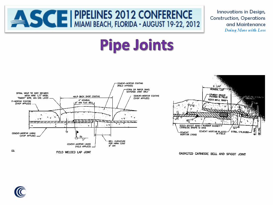
• In order to realize potential cost savings, the bid documents will allow contractors to bid the project with either all-welded joints, or with gasketted bell and spigot joints for portions not requiring thrust restraint.

Native Material as Backfill

• The soils along the alignment are suitable for trench-zone backfill.
• Substantial cost savings are possible if the native material from the trench excavation can be used for backfill in the pipe zone.
• The majority of the on-site granular soils with a sand equivalent (SE) greater than 30 are suitable for bedding and pipe zone backfill.
• SE is determined by ASTM Test Method D2419-91
• SE test can be done in less than 1 hour in the field
• Soil passing No. 4 sieve is mixed with a flocculating solution in a graduated cylinder.
• After settling, SE is measured as the ratio (in %) of the height of sand to the height of flocculated clay.
• High ratio indicates low clay fraction, resulting in ease of compaction and therefore better suitability as a bedding and pipe zone material.
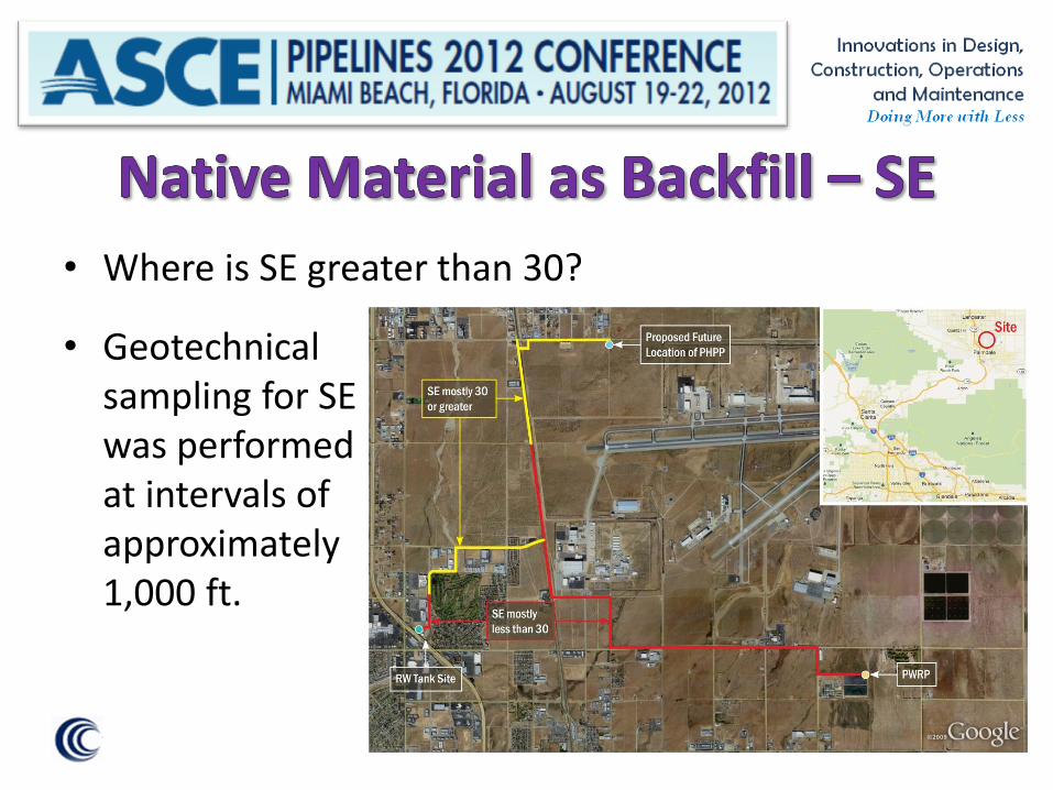
• Geotechnical sampling for SE was performed at intervals of approximately 1,000 ft.
• Where is SE greater than 30?

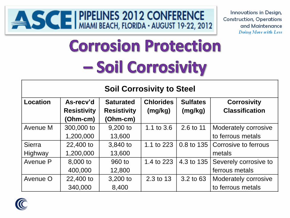
Corrosion Protection
Soil Corrosivity to Steel
Location As-recv’d
Resistivity
(Ohm-cm)
Saturated
Resistivity
(Ohm-cm)
Chlorides
(mg/kg)
Sulfates
(mg/kg)
Corrosivity
Classification
Avenue M 300,000 to
1,200,000
9,200 to
13,600
1.1 to 3.6 2.6 to 11 Moderately corrosive
to ferrous metals
Sierra
Highway
22,400 to
1,200,000
3,840 to
13,600
1.1 to 223 0.8 to 135 Corrosive to ferrous
metals
Avenue P 8,000 to
400,000
960 to
12,800
1.4 to 223 4.3 to 135 Severely corrosive to
ferrous metals
Avenue O 22,400 to
340,000
3,200 to
8,400
2.3 to 13 3.2 to 63 Moderately corrosive
to ferrous metals

• Although the soils are considered moderately to
severely corrosive, deep groundwater levels and typically dry desert soils allow cement-mortar coated steel.
• Corrosion monitoring test stations at 500 ft.
• Pipeline joints welded or to facilitate future cathodic protection if necessary.
• Factory applied coating for Copper pipe (AV piping)
Railroad and Creek Crossings

• Two crossings of the SCRRA railroad
• Typical jacked steel casing, 36-inch diameter
• Sufficient depth (minimum 3.5 casing diameters to springline) to prevent surface deformation

• Channel characteristics at
crossing: – Soft bottom
– Rip rap over geotextile embankment reinforcement
– Downstream scour control
• Reinforced concrete encasement of pipeline
• Keep encased pipeline below extents of embankment reinforcement
Key Lessons Learned
• Key Lessons Learned during planning and design for
the Phase 2 Recycled Water System:
– Recycled water can provide relief to a growing arid area with an increasingly-unreliable water supply.
– Regional water supply solutions require careful coordination with affected water agencies and communities
– Designing recycled water facilities for an uncertain hypothetical ultimate flow may not be the best use of current resources; nearer-term reliable projections of maximum use can provide a more cost effective design.
• Key Lessons Learned (Continued):
– Consideration should be given to owner/operator’s preferences and familiarity when evaluating materials of construction.
– Take advantage of suitable native soils for bedding and pipe-zone material.
– Consider typical soil moisture conditions when assessing the need to install cathodic protection.
– Open cut construction of stream crossings can still be a viable option in the 21st century.