Embed Size (px)
Citation preview
1/39
P3FY-A054-01
PRIMERGY S60!"#$%!"#$%!"#$%!"#$% !"#$%&'"()*+,-./0 PPIMERGY S601234564789:;<%:!=>?@A=BCD4:EFGH$%GIJ>KLMN<4OPPRIMERGY S60 QRSTHU%2VW%PSANArray ManagerQRSTHU"XY1Z[;<2@:EFGIJ1C\]>^O_>`a2bcd8M4F
2002e 1f ghijkl'
1 PRIMERGY S60!"#$%&'!"#$%&'!"#$%&'!"#$%&' !!m$%PPRIMERGY S60QRSTHU1Z[%:7$%no;:EF
1.1 ()*+()*+()*+()*+ OS GIJApqrs;<4O OS$tu"i@mEF
!"Microsoft® Windows® 2000 Server SP1tv !"Microsoft® Windows® 2000 Advanced Server SP1tv
1.2 ,-.,-.,-.,-.
&'()*+,-./0&'()*+,-./0&'()*+,-./0&'()*+,-./0 CD-ROM %123%123%123%123
PG-DA101wPRIMERGY S60x(*yzy.{|%PG-R1DA1wPRIMERGY S60 }~+���sy.{|>$%P���1��;<d8M4U>X�MN<4OP���QRSTH(ry
CD-ROMU$KLMN<4:��F!!>��m2�W�;��:E==�>%noM�<4789:EF
PRIMERGY ServerView CD-ROM %123%123%123%123 GIJ>$%PPRIMERGY ServerView V3.10L10UAKLMN<2@:EF� CD-ROMKL"STH>%��pr��(zA PRIMERGY L100/C200/F200=X�MN<4O��A?@:EA%���s��,$%PRIMERGY H200/N400/P200>���;<2@:EF PRIMERGY ServerView $�"IJ>�KLMNO��A?@:EA%�" $¡¢£;4�r¤¥�" CD-ROM1C¦]d8M4:EVB2§447;:EF
2/39
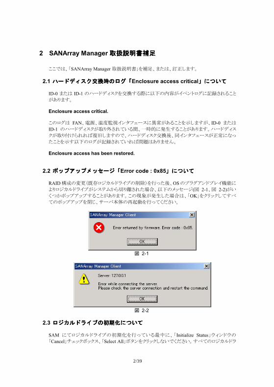
2 SANArray Manager!"#$%&'!"#$%&'!"#$%&'!"#$%&' !!m$%PSANArray ManagerQRSTHU1Z[%:7$%no;:EF
2.1 /*0123456789:;/*0123456789:;/*0123456789:;/*0123456789:;Enclosure access critical<=>?@<=>?@<=>?@<=>?@ ID-0 :7$ ID-1 "¨r©()*+1ª«EO >tu"¬A.®�s¯°>X±MNO!=A?@:EF Enclosure access critical. !"¯°$ FAN%²³%´#µ¶.�y��r*>·¸A?O!=1¹;:EA%ID-0 :7$ID-1 "¨r©()*+AQ@ºMN<4O»%¡¼½>¾¿EO!=A?@:EF¨r©()*+AQ@LÀÁNNÂÃÄ;:E"m%¨r©()*+ª«Å%�.�y��r*Ao¸>^Æ
7!=1¹Etu"¯°AX±MN<4NÂÇÈ$?@:��F Enclosure access has been restored.
2.2 )ABCABDAE*F;)ABCABDAE*F;)ABCABDAE*F;)ABCABDAE*F;Error code : 0x85<=>?@<=>?@<=>?@<=>?@ RAIDÉÊ"ËÌwÍί¤Ïz©}.Ð"ÑÒ|1ÓÆ7Å%OS"{}°,�©{-.ÔÕ>V@¯¤Ïz©}.ÐAÖ*×ØÙÁÚ@ÛMN7��%tu"Ü~Ýr¤(Þ 2-1%Þ 2-2)A4dßÙq~{,~{EO!=A?@:EF!"à�A¾¿;7��$%POKU1+á~+;<Eâ<"q~{,~{1ãä%pr�Gå"æçè1ÓÆ<d8M4F
4 2-1
4 2-2
2.3 9FGH0IJK8LMN=>?@9FGH0IJK8LMN=>?@9FGH0IJK8LMN=>?@9FGH0IJK8LMN=>?@
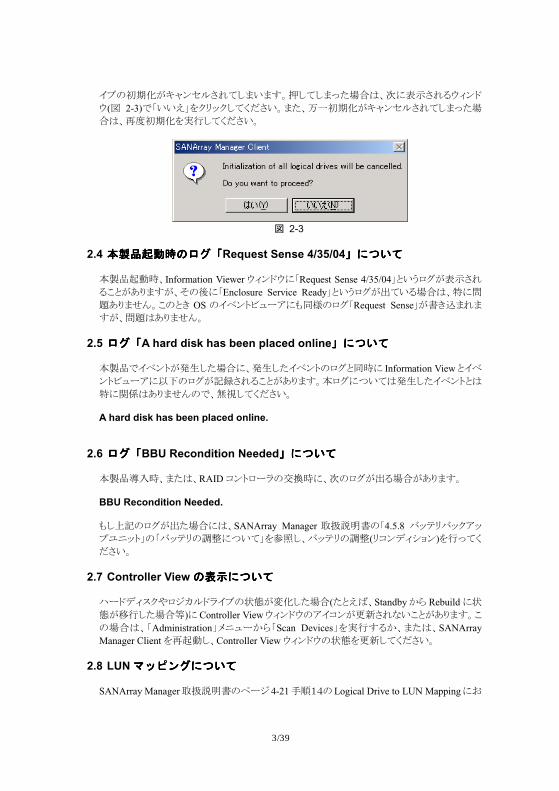
SAM ><¯¤Ïz©}.Ð"éêë1ÓÆ<4Oìí>%PInitialize StatusU�)�©�"PCancelUî�~+ï~+*%PSelect AllUïy�1+á~+;^4md8M4FEâ<"¯¤Ïz©}
3/39
.Ð"éêëAðñ�ÝzMN<;:4:EFò;<;:Æ7��$%ó>ô¹MNO�)�©
�(Þ 2-3)mP44õU1+á~+;<d8M4F:7%ö¡éêëAðñ�ÝzMN<;:Æ7��$%æ#éêë1÷Ó;<d8M4F
4 2-3
2.4 OP.QR789:;OP.QR789:;OP.QR789:;OP.QR789:;Request Sense 4/35/04<=>?@<=>?@<=>?@<=>?@
GIJçè¼%Information Viewer �)�©�>PRequest Sense 4/35/04U=4B¯°Aô¹MNO!=A?@:EA%�"Å>PEnclosure Service ReadyU=4B¯°Aø<4O��$%ù>ÇÈ?@:��F!"=9 OS ".®�súûr,>��ü"¯°PRequest SenseUAH9ý:N:EA%ÇÈ$?@:��F
2.5 9:;9:;9:;9:;A hard disk has been placed online<=>?@<=>?@<=>?@<=>?@ GIJm.®�sA¾¿;7��>%¾¿;7.®�s"¯°=�¼> Information View=.®�súûr,>tu"¯°AX±MNO!=A?@:EFG¯°>ß4<$¾¿;7.®�s=$
ù>þÿ$?@:��"m%!¶;<d8M4F A hard disk has been placed online.
2.6 9:;9:;9:;9:;BBU Recondition Needed<=>?@<=>?@<=>?@<=>?@ GIJ"#¼%:7$%RAID $�s¯r}"ª«¼>%ó"¯°AøO��A?@:EF BBU Recondition Needed. �;�X"¯°Aø7��>$%SANArray Manager QRSTH"P4.5.8 �~×á�~+,~{%&~sU"P�~×á"'(>ß4<U1)*;%�~×á"'((á$�()Ö¥�)1ÓÆ<d8M4F
2.7 Controller View8ST=>?@8ST=>?@8ST=>?@8ST=>?@ ¨r©()*++¯¤Ïz©}.Ð",-AËë;7��(7=õÂ%StandbyÙÁ Rebuild>,-A.Ó;7��/)>Controller View�)�©�",.$�AÌ£MN^4!=A?@:EF!"��$%PAdministrationUÜ&ûrÙÁPScan DevicesU1÷ÓEOÙ%:7$%SANArray Manager Client1æçè;%Controller View �)�©�",-1Ì£;<d8M4F
2.8 LUNUAVW:=>?@UAVW:=>?@UAVW:=>?@UAVW:=>?@ SANArray ManagerQRSTH"xr¤ 4-210123"Logical Drive to LUN Mapping>2
4/39
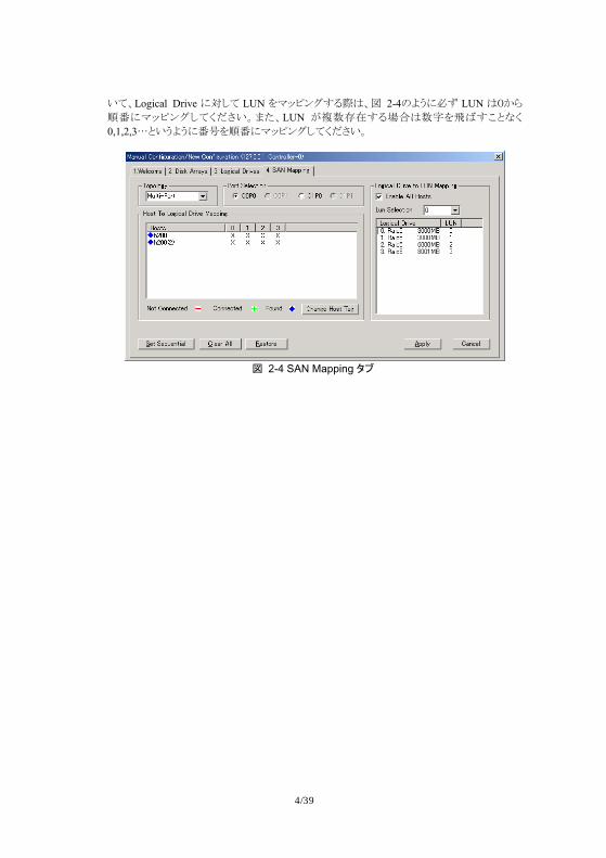
4<%Logical Drive >�;< LUN 1�~4�°EO $%Þ 2-4"VB>`a LUN $5ÙÁ1¢>�~4�°;<d8M4F:7%LUN A67Î8EO��$791:ÂE!=^d0,1,2,3;=4BVB>¢<11¢>�~4�°;<d8M4F
4 2-4 SAN Mapping 05
5/39
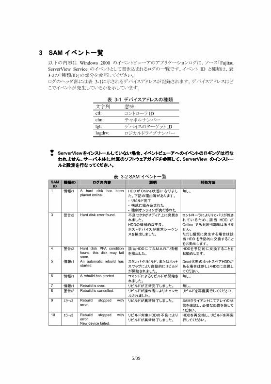
3 SAMJXW+YZJXW+YZJXW+YZJXW+YZ tu"¬$ Windows 2000 ".®�súûr,",{á=rÖ¥�¯°>%�r*PFujitsu ServerView ServiceU".®�s=;<H9ý:NO¯°"¡>mEF.®�s ID =?@$%ô 3-2"P?@/IDU"AB1)*;<d8M4F ¯°"C~DA>$ô 3-1>¹MNO(�.*,©-*AX±MN:EF(�.*,©-*$E!m.®�sA¾¿;<4OÙ1¹;<4:EF
6 3-1 .789:;<9=>? F9G HI ctl: $�s¯r} ID chn: îñJzK��r tgt: (�.*"yrL~s ID logdrv: ¯¤Ïz©}.ÐK��r
!" ServerView@8A9B/CD32E2FGH8IABJK/:L=8IAB=MNAOPQE@8A9B/CD32E2FGH8IABJK/:L=8IAB=MNAOPQE@8A9B/CD32E2FGH8IABJK/:L=8IAB=MNAOPQE@8A9B/CD32E2FGH8IABJK/:L=8IAB=MNAOPQE
RSTUVWX/7YZ%[\=]^B_`:a8;@bcD3HRSTUVWX/7YZ%[\=]^B_`:a8;@bcD3HRSTUVWX/7YZ%[\=]^B_`:a8;@bcD3HRSTUVWX/7YZ%[\=]^B_`:a8;@bcD3HServerView =8A9B/=8A9B/=8A9B/=8A9B/
CCCCdef@QEg3hij2Wdef@QEg3hij2Wdef@QEg3hij2Wdef@QEg3hij2W
6 3-2 SAM8IABkl SAM
ID >?>?>?>?/ID MO=mnMO=mnMO=mnMO=mn +,+,+,+, opqropqropqropqr
1 st/1 A hard disk has been placed online.
HDDuOnlinevw%ExTDyWz{=|}~u�xT�W - �JC;�� - ��%���TSy - ���A�8Au�QjSy
�DW
3 ��/2 Hard disk error found.
����0u�.�:�%��j
STDyW HDD=���E��W �9B.789u�� /¡A
9@¢£DTDyW
¤ABM/�%¥x�¦7�u§j
S32¨y©Hª« HDD u
Online ¬�¨x®¯P�xTUVW yiD°±%�²�¨FGPª
« HDD @³´�%µ¶�¨·d@¸¹©DT�W
4 ��/2 Hard disk PFA condition found, this disk may fail soon.
ª«HDD%3S.M.A.R.T.st@¢£DyW
HDD@³´�%µ¶�¨·d@¸¹©DT�W
5 st/1 An automatic rebuild has started.
90A78�JC;HTyP�ºB
9»º¼%¥x½¾�%�JC;
u¿ÀjSTDyW
Deadvw=�ºB9Á:HDDu�¨FGPÂD2HDD%µ¶D3hij2W
6 st/1 A rebuild has started. ¤ÃA;%¥¨�JC;u¿Àj
STDyW �DW
7 st/1 Rebuild is over. �JC;uÄ���DTDyW �DW 8 ��/2 Rebuild is cancelled. �JC;uÅÆÇ%¥xÈÉA�
CjSTDyW �JC;@ÊË�QD3hij2W
9 ÌÍÎ/3 Rebuild stopped with error.
�JC;u��Ï�DTDyW SAM��8:AB%3:<8=vw@ÐÑDHÒÓEpÔ@§D3
hij2W 10 ÌÍÎ/3 Rebuild stopped with
error. New device failed.
�JC;oÕHDD=��%¥x�JC;u��Ï�DTDyW
HDD@ʵ¶DH�JC;@Ê�QD3hij2W
6/39
SAM ID
>?>?>?>?/ID MO=mnMO=mnMO=mnMO=mn +,+,+,+, opqropqropqropqr
11 ÌÍÎ/3 Rebuild stopped because logical drive failed.
�JC;]/9.�9�%Ö×=
��5Mº�u�gyy©H�J
C;u���DTDyW
Criticalvw=:<8ØÙ./0@7º�:º¼D3hij2WÚ%
��5Mº�u¢£jSyHDD@µ¶ÛH:<8@Ê�Ü/ÝÞßDHÊ�ÜDy:<8%7º�
:º¼./0@�9B:D3hij
2W 12 ÌÍÎ/3 A hard disk has failed. HDDuàáDTDyW )*+,-@bcDHDeadvw
%Egyâ/;.�9�=µ¶ã�
JC;Æä@Qg3hij2W 13 st/1 A new hard disk has been
found. Ây%HDD@¢£DTDyWz{=¥åEFG%MOjST�W - HDD@æçDy - ¤ABM/�=èéuêëjSy - ¤ABM/�@æçDy - 9ìí@�5/BDy
�DW
14 st/1 A hard disk has been removed.
HDDu)xîjSTDyW SAM��8:AB%3:<8=vw@ÐÑDHÒÓEpÔ@§D3
hij2W 19 ��/2 SCSI command timeout
on hard device. ¤ÃA;08í:_B@¢£DT
DyW �DW
22 ��/2 Parity error found. ï�ì�ð�/@¢£DTDyW �DW 25 st/1 SCSI device reset. ^ñ/í_`:u�¦7�=y©
��ºB@�QDTDyW �DW
50 ��/2 Physical device status changed to offline.
HDD=vwuOffline%ExTDyW
�DW
51 ��/2 Physical device status changed to Hot Spare.
HDD=vwuHotSpare%ExTDyW
�DW
52 ��/2 Physical device status changed to rebuild.
HDD=vwuRebuilding%ExTDyW
�DW
54 ��/2 Physical device failed to start.
HDD=ò¾%óôDTDyW SAM��8:AB%3:<8=vw@ÐÑDHÒÓEpÔ@§D3
hij2W 57 ÌÍÎ/3 Physical drive missing on
startup. ò¾õ%HDDu¢£jSTUV¬DyW
SAM��8:AB%3:<8=vw@ÐÑDHÒÓEpÔ@§D3
hij2W 59 ��/2 Physical drive is switching
from a channel to the other channel.
HDD=ö÷øÔuùújSTDyW�¨2PHûÉüCuùú
jSTDyW
SAM��8:AB%3:<8=vw@ÐÑDHÒÓEpÔ@§D3
hij2W 96 ÌÍÎ/3 Device Loop Id Conflict
(Soft Addressing) Detected.
HDD=Loop IDuýGD32T�W
þÿuÒÓ¬�W!"#«$%
&%!'(hij2W
128 st/1 Consistency check is started.
k)*û`º�u¿ÀjSTD
yW �DW
129 st/1 Consistency check is finished.
k)*û`º�uÄ�Ï�DT
DyW �DW
130 ��/2 Consistency check is cancelled.
k)*û`º�uÈÉA�CjS
TDyW ÒÓ¬�S+Hk)*û`º�@
ÊË�QD3hij2W 131 ÌÍÎ/3 Consistency check on
logical drive error. k)*û`º�¬ð�/@¢£D
TDyW Yð�/u�²DyFGP
,SANArray Manager)*+,- - = , 4.6.1 Consistency Check-@bcD3hij2W
132 ÌÍÎ/3 Consistency check on logical drive failed.
.ÙØ=M/¦C;�85=�
�%¥xHConsistency Checku��Ï�DTDyW
SAM��8:AB%3:<8=vw@ÐÑDHÒÓEpÔ@§D3
hij2W 133 ÌÍÎ/3 Consistency check failed
due to physical device failure.
HDD��%¥xHConsistency Checku��Ï�DTDyW
SAM��8:AB%3:<8=vw@ÐÑDHÒÓEpÔ@§D3
hij2W
7/39
SAM ID
>?>?>?>?/ID MO=mnMO=mnMO=mnMO=mn +,+,+,+, opqropqropqropqr
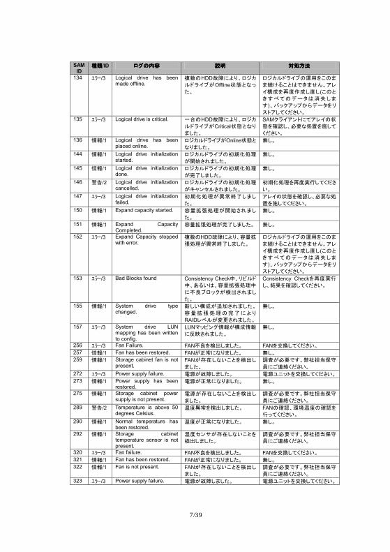
134 ÌÍÎ/3 Logical drive has been made offline.
0×=HDDàá%¥xHM/¦C;�85uOfflinevwdEgyW
M/¦C;�85=1#@·=T
T23¨·dP¬4TUVW:<
8��@ÊËÆ�D5D(·=d4�63=./0P7óDT
�)H7º�:º¼ØÙ./0@�9B:D3hij2W
135 ÌÍÎ/3 Logical drive is critical. k8=HDDàá%¥xHM/¦C;�85uCriticalvwdExTDyW
SAM��8:AB%3:<8=vw@ÐÑDHÒÓEpÔ@§D3
hij2W 136 st/1 Logical drive has been
placed online. M/¦C;�85uOnlinevwdExTDyW
�DW
144 st/1 Logical drive initialization started.
M/¦C;�85=ÝÞßp|
u¿ÀjSTDyW �DW
145 st/1 Logical drive initialization done.
M/¦C;�85=ÝÞßp|
u��DTDyW �DW
146 ��/2 Logical drive initialization cancelled.
M/¦C;�85=ÝÞßp|
uÈÉA�CjSTDyW ÝÞßp|@ÊË�QD3hij
2W 147 ÌÍÎ/3 Logical drive initialization
failed. ÝÞßp|u��Ï�DTD
yW :<8=vw@ÐÑDHÒÓEp
Ô@§D3hij2W 150 st/1 Expand capacity started. n9:;p|u¿ÀjSTD
yW �DW
151 st/1 Expand Capacity Completed.
n9:;p|u��DTDyW �DW
152 ÌÍÎ/3 Expand Capacity stopped with error.
0×=HDDàá%¥xHn9:;p|u��Ï�DTDyW
M/¦C;�85=1#@·=T
T23¨·dP¬4TUVW:<
8��@ÊËÆ�D5D(·=d4�63=./0P7óDT
�)H7º�:º¼ØÙ./0@�9B:D3hij2W
153 ÌÍÎ/3 Bad Blocks found Consistency Check<H�JC;<H�¨2PHn9:;p|<
%��5Mº�u¢£jSTD
yW
Consistency Check@ÊË�QDH=>@ÐÑD3hij2W
155 st/1 System drive type changed.
ÂD2��uæçjSTDyW
n9:;p|=��%¥x
RAID<ICuùújSTDyW
�DW
157 ÌÍÎ/3 System drive LUN mapping has been written to config.
LUNú?AOstu��st%@AjSTDyW
�DW
256 ÌÍÎ/3 Fan Failure. FAN��@¢£DTDyW FAN@µ¶D3hij2W 257 st/1 Fan has been restored. FANuÄ�%ExTDyW �DW 259 st/1 Storage cabinet fan is not
present. FANuBCDE2·d@¢£DTDyW
þÿuÒÓ¬�W!"#«$%
&%!'(hij2W 272 ÌÍÎ/3 Power supply failure. èéuàáDTDyW èéDEºB@µ¶D3hij2W 273 st/1 Power supply has been
restored. èéuÄ�%ExTDyW �DW
275 st/1 Storage cabinet power supply is not present.
èéuBCDE2·d@¢£D
TDyW þÿuÒÓ¬�W!"#«$%
&%!'(hij2W 289 ��/2 Temperature is above 50
degrees Celsius. FË��@¢£DTDyW FAN=ÐÑHGHFË=ÐÑ@
Qg3hij2W 290 st/1 Normal temperature has
been restored. FËuÄ�%ExTDyW �DW
292 st/1 Storage cabinet temperature sensor is not present.
FË�AXuBCDE2·d@
¢£DTDyW þÿuÒÓ¬�W!"#«$%
&%!'(hij2W
320 ÌÍÎ/3 Fan failure. FAN��@¢£DTDyW FAN@µ¶D3hij2W 321 st/1 Fan has been restored. FANuÄ�%ExTDyW �DW 322 st/1 Fan is not present. FANuBCDE2·d@¢£D
TDyW þÿuÒÓ¬�W!"#«$%
&%!'(hij2W 323 ÌÍÎ/3 Power supply failure. èéuàáDTDyW èéDEºB@µ¶D3hij2W
8/39
SAM ID
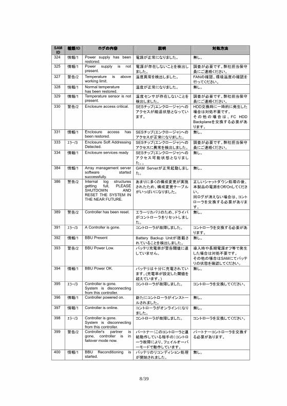
>?>?>?>?/ID MO=mnMO=mnMO=mnMO=mn +,+,+,+, opqropqropqropqr
324 st/1 Power supply has been restored.
èéuÄ�%ExTDyW �DW
325 st/1 Power supply is not present.
èéuBCDE2·d@¢£D
TDyW þÿuÒÓ¬�W!"#«$%
&%!'(hij2W 327 ��/2 Temperature is above
working limit. FË��@¢£DTDyW FAN=ÐÑHGHFË=ÐÑ@
Qg3hij2W 328 st/1 Normal temperature
has been restored. FËuÄ�%ExTDyW �DW
329 st/1 Temperature sensor is not present.
FË�AXuBCDE2·d@
¢£DTDyW þÿuÒÓ¬�W!"#«$%
&%!'(hij2W 330 ��/2 Enclosure access critical. SESûº¼(ðA�M//É)L=
:��9uIJvwdEg32
T�W
HDDµ¶õ%kõ�%�²DyFGPop�Ó¬�W K=L=FGP H FC HDD Backplane@µ¶�¨ÒÓu�xT�W
331 st/1 Enclosure access has been restored.
SESûº¼(ðA�M//É)L=:��9uÄ�%ExTDyW
�DW
333 ÌÍÎ/3 Enclosure Soft Addressing Detected.
SESûº¼(ðA�M//É)L=:��9%��@¢£DTDyW
þÿuÒÓ¬�W!"#«$%
&%!'(hij2W 334 st/1 Enclosure services ready SESûº¼(ðA�M//É)L=
:��9MNvwdExTD
yWW
�DW
384 st/1 Array management server software started successfully.
GAM ServeruÄ�ò¾DTDyW
�DW
386 ��/2 Internal log structures getting full, PLEASE SHUTDOWN AND RESET THE SYSTEM IN THE NEAR FUTURE.
�Tx%Öh=��ùúu�§
jSyy©H��ùúì/5C
u2gO2%ExTDyW
ÄD2 ɺBP_Ap|=ÛH
YQR=èé@Off/OnD3hij2W SMOu7TE2FGPH¤AB
M/�@µ¶�¨ÒÓu�xT
�W 389 ��/2 Controller has been reset. ð�/�¦7�=y©H;�87
u¤ABM/�@��ºBDTD
yW
�DW
391 ÌÍÎ/3 A Controller is gone. ¤ABM/�uàáDTDyW ¤ABM/�@µ¶�¨ÒÓu�
xT�W 392 st/1 BBU Present Battery Backup Unituö÷j
S32¨·d@¢£DTDyW �DW
393 ��/2 BBU Power Low. 7ºì�UèVu��WX%Y
D32TUVW Zëõ[\Þèé�^~¬�²
DyFGPop�Ó¬�W K=L=FGPSAM%37ºì�=vw@ÐÑD3hij2W
394 st/1 BBU Power OK. 7ºì�P]^%UèjS32
T�W(UèVuefDyWX@_T32T�W)
�DW
395 ÌÍÎ/3 Controller is gone. System is disconnecting from this controller.
¤ABM/�uàáDTDyW ¤ABM/�@µ¶D3hij2W
396 st/1 Controller powered on. Ây%¤ABM/�u8A9B/
CjSTDyW �DW
397 st/1 Controller is online. ¤ABM/�u�A�8A%Ex
TDyW �DW
398 ÌÍÎ/3 Controller is gone. System is disconnecting from this controller.
¤ABM/�uàáDTDyW ¤ABM/�@µ¶D3hij2W
399 ��/2 Controller's partner is gone, controller is in failover mode now.
ï/B`/a·=¤ABM/�d'
=¾ÆD32¨bc=d¤ABM
/�àá%¥xH^`8C�/7
/e/;¬¾ÆD32T�W
ï/B`/¤ABM/�@µ¶�
¨ÒÓu�xT�W
400 st/1 BBU Reconditioning is started.
7ºì�=�¤A.� fAp|
u¿ÀjSTDyW �DW
9/39
SAM ID
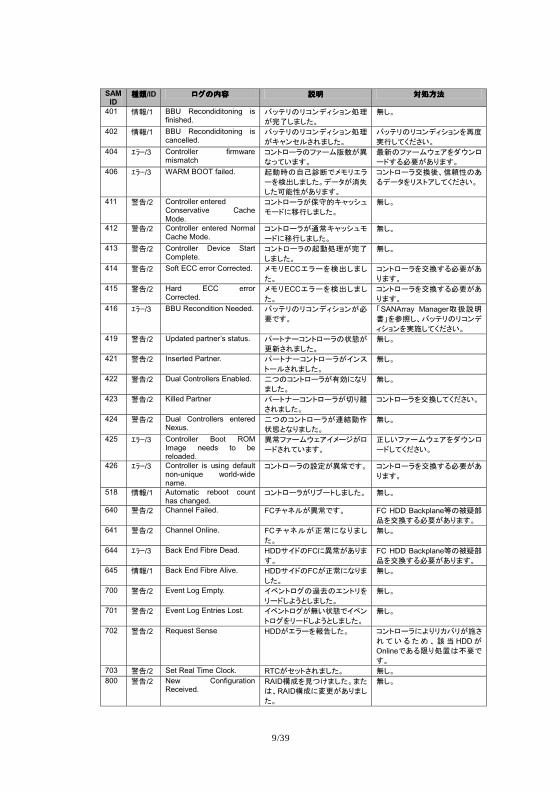
>?>?>?>?/ID MO=mnMO=mnMO=mnMO=mn +,+,+,+, opqropqropqropqr
401 st/1 BBU Recondiditoning is finished.
7ºì�=�¤A.� fAp|
u��DTDyW �DW
402 st/1 BBU Recondiditoning is cancelled.
7ºì�=�¤A.� fAp|
uÈÉA�CjSTDyW 7ºì�=�¤A.� fA@ÊË
�QD3hij2W 404 ÌÍÎ/3 Controller firmware
mismatch ¤ABM/�=^ñ/í(×u�
Eg32T�W gÂ=^ñ/í_`:@P_AM
/;�¨ÒÓu�xT�W 406 ÌÍÎ/3 WARM BOOT failed. ò¾õ=½hij¬�e�ð�
/@¢£DTDyW./0u7ó
DyMN*u�xT�W
¤ABM/�µ¶ÛHkl*=�
¨./0@�9B:D3hij2W
411 ��/2 Controller entered Conservative Cache Mode.
¤ABM/�u$%�Èɺ K
e/;%mQDTDyW �DW
412 ��/2 Controller entered Normal Cache Mode.
¤ABM/�un�Èɺ Ke
/;%mQDTDyW �DW
413 ��/2 Controller Device Start Complete.
¤ABM/�=ò¾p|u��
DTDyW �DW
414 ��/2 Soft ECC error Corrected. �e�ECCð�/@¢£DTDyW
¤ABM/�@µ¶�¨ÒÓu�
xT�W 415 ��/2 Hard ECC error
Corrected. �e�ECCð�/@¢£DTDyW
¤ABM/�@µ¶�¨ÒÓu�
xT�W 416 ÌÍÎ/3 BBU Recondition Needed. 7ºì�=�¤A.� fAuÒ
Ó¬�W ,SANArray Manager)*+,--@bcDH7ºì�=�¤A.
� fA@�§D3hij2W 419 ��/2 Updated partner’s status. ï/B`/¤ABM/�=vwu
úÂjSTDyW �DW
421 ��/2 Inserted Partner. ï/B`/¤ABM/�u8A9
B/CjSTDyW �DW
422 ��/2 Dual Controllers Enabled. o1=¤ABM/�upq%Ex
TDyW �DW
423 ��/2 Killed Partner ï/B`/¤ABM/�urxs
jSTDyW ¤ABM/�@µ¶D3hij2W
424 ��/2 Dual Controllers entered Nexus.
o1=¤ABM/�u'=¾Æ
vwdExTDyW �DW
425 ÌÍÎ/3 Controller Boot ROM Image needs to be reloaded.
��^ñ/í_`:8�//uM
/;jS32T�W ÄD2^ñ/í_`:@P_AM
/;D3hij2W
426 ÌÍÎ/3 Controller is using default non-unique world-wide name.
¤ABM/�=efu��¬�W ¤ABM/�@µ¶�¨ÒÓu�xT�W
518 st/1 Automatic reboot count has changed.
¤ABM/�u�5/BDTDyW �DW
640 ��/2 Channel Failed. FCûÉüCu��¬�W FC HDD Backplane~=tuvR@µ¶�¨ÒÓu�xT�W
641 ��/2 Channel Online. FCûÉüCuÄ�%ExTDyW
�DW
644 ÌÍÎ/3 Back End Fibre Dead. HDDX8;=FC%��u�xT�W
FC HDD Backplane~=tuvR@µ¶�¨ÒÓu�xT�W
645 st/1 Back End Fibre Alive. HDDX8;=FCu�%ExTDyW
�DW
700 ��/2 Event Log Empty. 8IABMO=wx=ðAB�@
�/;D¥ådDTDyW �DW
701 ��/2 Event Log Entries Lost. 8IABMOu�2vw¬8IA
BMO@�/;D¥ådDTDyW �DW
702 ��/2 Request Sense HDDuð�/@t�DyW ¤ABM/�%¥x�¦7�u§j
S32¨y© Hª« HDDuOnline¬�¨xpÔP�Ó¬�W
703 ��/2 Set Real Time Clock. RTCu�ºBjSTDyW �DW 800 ��/2 New Configuration
Received. RAID��@�13TDyWTyPHRAID��%ùúu�xTDyW
�DW
10/39
SAM ID
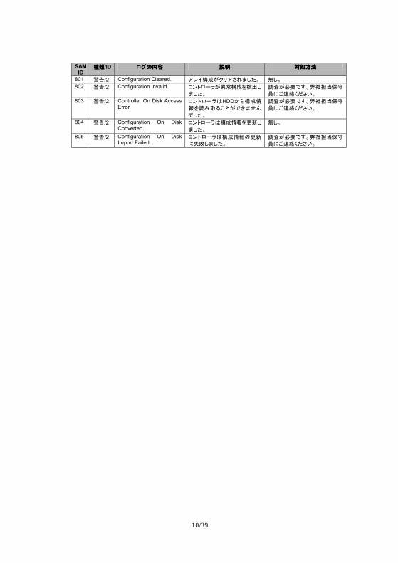
>?>?>?>?/ID MO=mnMO=mnMO=mnMO=mn +,+,+,+, opqropqropqropqr
801 ��/2 Configuration Cleared. :<8��u��:jSTDyW �DW 802 ��/2 Configuration Invalid ¤ABM/�u����@¢£D
TDyW þÿuÒÓ¬�W!"#«$%
&%!'(hij2W 803 ��/2 Controller On Disk Access
Error. ¤ABM/�PHDDØÙ��st@y�)¨·du¬4TUV
¬DyW
þÿuÒÓ¬�W!"#«$%
&%!'(hij2W
804 ��/2 Configuration On Disk Converted.
¤ABM/�P��st@úÂD
TDyW �DW
805 ��/2 Configuration On Disk Import Failed.
¤ABM/�P��st=úÂ
%óôDTDyW þÿuÒÓ¬�W!"#«$%
&%!'(hij2W
11/39
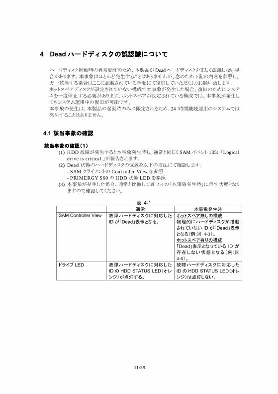
4 Dead/*012348[\]=>?@/*012348[\]=>?@/*012348[\]=>?@/*012348[\]=>?@ ¨r©()*+çè¼"·¸èM"76%GIJADead¨r©()*+1o;d�N;^4��A?@:EFGO�$P=�E¾¿EO!=$?@:��A%Q"76uX"¬1)*;%
ö¡RSEO��$!!>X�MN<4O01><ÃÄ;<478dVB2§4T;:EF U~s*x,()*+AVWMN<4^4ÉÊmGO�A¾¿;7��%ÃÄ"76>Ö*×
Ø1¡#XYEO`ZA?@:EFU~s*x,AVWMN<4OÉÊm$%GO�A¾¿;
<�Ö*×Ø[]í"ÃÄA\ÕmEF GO�"¾¿$%GIJ"çè¼"c>]WMNO76%24 ¼»^_[]"Ö*×Øm$¾¿EO!=$?@:��F
4.1 ^_`a8^_`a8^_`a8^_`a8b\b\b\b\ ª«zÕ=ÐÑa{dª«zÕ=ÐÑa{dª«zÕ=ÐÑa{dª«zÕ=ÐÑa{d
(1) HDD`aA¾¿EO=GO�¾¿¼�%i¸=�äd SAM.®�s 135: PLogical drive is critical.UAbcMN:EF
(2) Dead,-"¨r©()*+"d01tu"ef><��;:EF - SAM +}.,�s" Controller View1)* - PRIMERGY S60" HDD,- LED1)*
(3) GO�A¾¿;7��%i¸=gh;<ô 4-1"PGO�¾¿¼U>¹E,-=^@:E"m��;<d8M4F
6 4-1
n� YzÕ�²õ SAM Controller View àáâ/;.�9�%o|Dy
IDu,Dead-6}dE¨W �ºB9Á:�D=�� ~|�%â/;.�9�uö÷
jS32E2 IDu,Dead-6}dE¨a�:Þ 4-3dW �ºB9Á:px=�� ,Dead-6}dEg32¨ ID uBCDE2vwdE¨a� :Þ 4-6dW
;�85 LED àáâ/;.�9�%o|Dy
ID= HDD STATUS LEDa�<A/du���¨W
àáâ/;.�9�%o|Dy
ID= HDD STATUS LEDa�<A/dP��DE2W
12/39
ª«zÕ=ÐÑa�dª«zÕ=ÐÑa�dª«zÕ=ÐÑa�dª«zÕ=ÐÑa�d
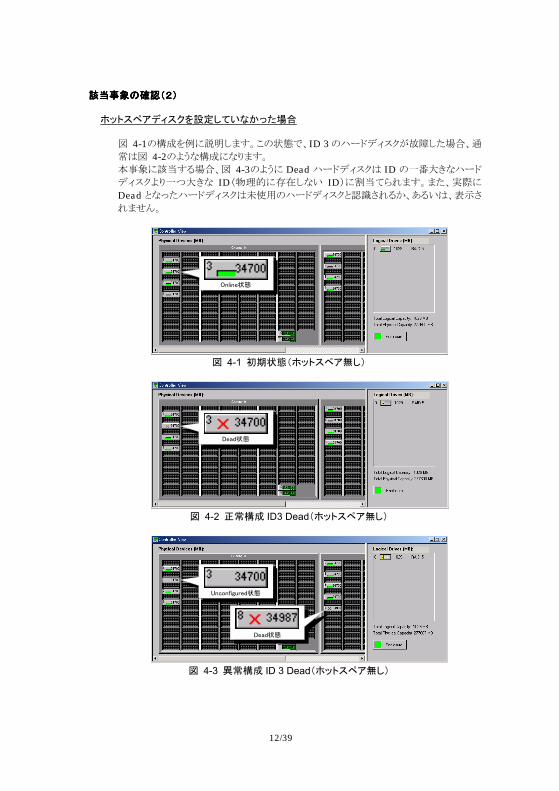
�ºB9Á:.�9�@efD32EØgyFG Þ 4-1"ÉÊ1i>ST;:EF!",-m%ID 3"¨r©()*+A`a;7��%i¸$Þ 4-2"VB^ÉÊ>^@:EF GO�>RSEO��%Þ 4-3"VB> Dead ¨r©()*+$ ID "¡¢j9^¨r©()*+V@¡ßj9^ IDw�k½>Î8;^4 ID|>lS<ÁN:EF:7%÷ >Dead =^Æ7¨r©()*+$m¦]"¨r©()*+=�NMNOÙ%?O4$%ô¹MN:��F
������vw
4 4-1 ÝÞvwa�ºB9Á:�Dd
����vw
4 4-2 Ä��� ID3 Deada�ºB9Á:�Dd
������������vw
����vw
4 4-3 ���� ID 3 Deada�ºB9Á:�Dd
13/39
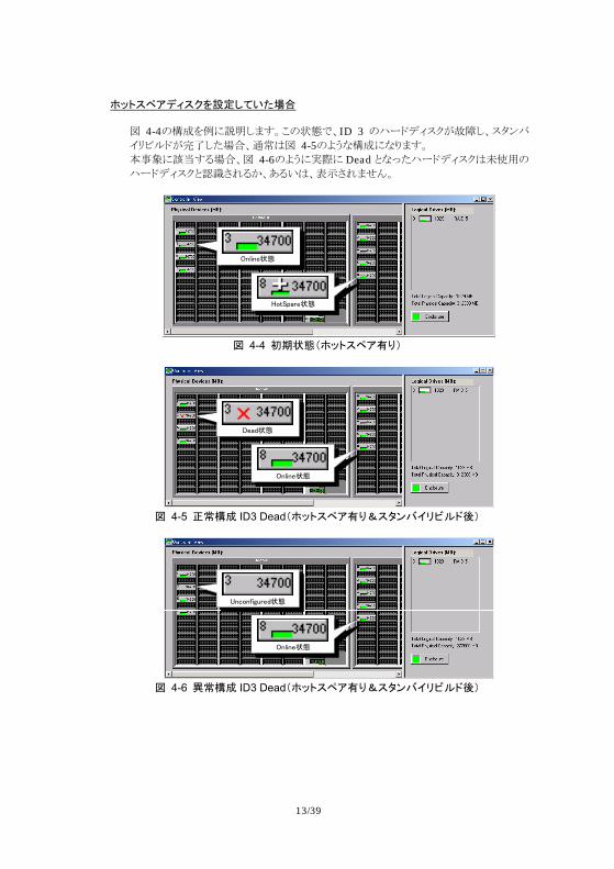
�ºB9Á:.�9�@efD32yFG Þ 4-4"ÉÊ1i>ST;:EF!",-m%ID 3 "¨r©()*+A`a;%*y��.áúz©Ano;7��%i¸$Þ 4-5"VB^ÉÊ>^@:EF GO�>RSEO��%Þ 4-6"VB>÷ > Dead =^Æ7¨r©()*+$m¦]"¨r©()*+=�NMNOÙ%?O4$%ô¹MN:��F
������vw
��������vw
4 4-4 ÝÞvwa�ºB9Á:pxd
����vw
������vw
4 4-5 Ä��� ID3 Deada�ºB9Á:px�90A78�JC;Ûd
������������vw
������vw
4 4-6 ���� ID3 Deada�ºB9Á:px�90A78�JC;Ûd
14/39
4.2 cdefcdefcdefcdef
�ºB9Á:.�9�@efD32EØgy�ºB9Á:.�9�@efD32EØgy�ºB9Á:.�9�@efD32EØgy�ºB9Á:.�9�@efD32EØgyFGFGFGFG !"��%Gà�A¾¿EO=%Dead=^Æ7¨r©()*+$ô¹MN^4%:7$%m¦],-=;<ô¹MN%p"d0(÷ >$¨r©()*+"Î8;<4^4d0)> Dead ¨r©()*+()*+Aô¹MN:EF 1. SAM+}.,�s"Controller View�)�©�m%÷ >$¨r©()*+"Î8;^4
*¯~s> Dead,-"¨r©()*+Aô¹MN<4O!=1��;<d8M4F
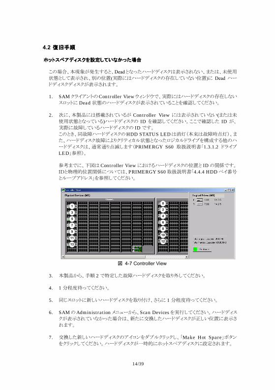
2. ó>%GIJ>$q�MN<4OA Controller View >$ô¹MN<4^4(:7$m¦],-=^Æ<4O)¨r©()*+" ID 1��;<d8M4F!!m��;7 ID A%÷ >`a;<4O¨r©()*+" IDmEF !"=9%�`a¨r©()*+"HDD STATUS LED$rswGt$`a¼us|%:7%¨r©()*+`a>V@+á×)Ïz,-=^Æ7¯¤Ïz©}.Ð1ÉÊEO�"¨
r©()*+$%i¸i@uv;:EwPRIMERGY S60 QRSTHP1.3.1.2 ©}.ÐLEDU)*|F )w:m>%uÞ$ Controller View>2ÀO¨r©()*+"d0= ID"þÿmEFxy=�k½d0þÿ>ß4<$%PRIMERGY S60QRSTHP4.4.4 HDD®.¢<=zr{,©-*U1)*;<d8M4F
1
3
5
7
9
11
13
0
2
4
6
8
10
12
4 4-7 Controller View
3. GIJÙÁ%01 2mùW;7`a¨r©()*+1Q@º;<d8M4F
4. 1Bz#{Æ<d8M4F
5. �ä*¯~s>£;4¨r©()*+1Q@LÀ%MÁ> 1Bz#{Æ<d8M4F
6. SAM"AdministrationÜ&ûrÙÁ%Scan Devices1÷Ó;<d8M4F¨r©()*
+Aô¹MN<4^ÙÆ7��$%£7>ª«;7¨r©()*+Ao;4d0>ô¹M
N:EF
7. ª«;7£;4¨r©()*+",.$�1DÐz+á~+;%PMake Hot SpareUïy�1+á~+;<d8M4F¨r©()*+A¡¼½>U~s*x,()*+>VWMN:EF
15/39
8. pr�1Öñ~sD��;7Å%GIJ"²³1|=;<d8M4F
9. GIJ"²³1#N<d8M4F
10. pr�1çè;%SAMÙÁª«;7¨r©()*+w¡¼½>U~s*x,()*+>VW
;7¨r©()*+|Aáúz©,-m?O!=1��;<d8M4F
11. áúz©Ano;7Á%ÃÄnomEF
�ºB9Á:.�9�@efD32yFG�ºB9Á:.�9�@efD32yFG�ºB9Á:.�9�@efD32yFG�ºB9Á:.�9�@efD32yFG Gà�A¾¿EO=%Dead=^Æ7¨r©()*+Aô¹MN^4%:7$%m¦],-=;<ô¹MN:EF 1. SAM+}.,�s"Controller} View�)�©�m%U~s*x,áúz©A~è½>÷Ó
MN<4O!=1��;<d8M4F U~s*x,áúz©Ano;<4O!=1��;7Á%GIJ>$q�MN<4OA
Controller View>$ô¹MN<4^4(:7$m¦],-=^Æ<4O)¨r©()*+" ID1��;<d8M4F!!m��;7 IDA÷ >`a;<4O¨r©()*+" IDmEFÞ 4-7$¨r©()*+1�zq�;<4O��"¨r©()*+"q�d0= ID"þÿmEF¨r©()*+Aô¹MN<4^4��$Þ1)w> ID 1ùW;<d8M4F xy=�k½d0þÿ>ß4<$%PRIMERGY S60QRSTHP4.4.4 HDD®.¢<=zr{,©-*U1)*;<d8M4F
2. GIJÙÁ%01�mùW;7`a¨r©()*+1Q@º;<d8M4F
3. 2Bz#{Æ<d8M4F
4. �ä*¯~s>£;4¨r©()*+1Q@LÀ%MÁ>2Bz#{Æ<d8M4F
5. SAM" Administration Ü&ûrÙÁ%Scan Device1÷Ó;<d8M4F¨r©()*+Aô¹MN<4^ÙÆ7��$%£7>ª«;7¨r©()*+Ao;4d0>ô¹M
N:EF
6. ª«;7£;4¨r©()*+",.$�1DÐz+á~+;%PMake Hot SpareUïy�1+á~+;<d8M4F¨r©()*+AU~s*x,()*+>VWMN:EF
7. t�mnomEF
Microsoft%Windows%Windows NT$��Microsoft Corporation"���W�"�"�>2ÀO�±��mEF Global Array Manager%SANArray Manager$%��Mylex'"��mEF

16/39
17/39
PRIMERGY S60 Supplement
Thank you for your purchase of the Fujitsu RAID Device. This document provides additional explanations for the User Guide that is supplied with this product. Read this document before you start using this product.
January 2002, Fujitsu Limited
1 Checking the Items Supplied Ensure that all of the following items are included in the package before using this product. If any items are missing, contact the Fujitsu service representative.
!"RAID storage subsystem whiRAID storage subsystem whiRAID storage subsystem whiRAID storage subsystem which includes:ch includes:ch includes:ch includes: - 1 unit of RAID Controller - 2 units of Power Supply - 3 units of Hard Disk Drive
!"AC cables (2 pieces)AC cables (2 pieces)AC cables (2 pieces)AC cables (2 pieces) !"User Guide CDUser Guide CDUser Guide CDUser Guide CD----ROMROMROMROM !"Wrist StrapWrist StrapWrist StrapWrist Strap !"1 Set of Metallic Parts for Rack1 Set of Metallic Parts for Rack1 Set of Metallic Parts for Rack1 Set of Metallic Parts for Rack----mount (attached only for rackmount (attached only for rackmount (attached only for rackmount (attached only for rack----mount model)mount model)mount model)mount model) !"Key (2 pieces)Key (2 pieces)Key (2 pieces)Key (2 pieces) !"Battery ReplacemenBattery ReplacemenBattery ReplacemenBattery Replacement Stickert Stickert Stickert Sticker !"PRIMERGY ServerView V3.10L10 (CDPRIMERGY ServerView V3.10L10 (CDPRIMERGY ServerView V3.10L10 (CDPRIMERGY ServerView V3.10L10 (CD----ROM)*ROM)*ROM)*ROM)*
* Though the document attached to the PRIMERGY ServerView may show that the supported servers are PRIMERGY L100, C200 and F200. The ServerView also supports PRIMERGY H200, N400 and P200. The ServerView CD-ROM may be attached to other products. Use the latest version of the CD-ROM, if you have two or more ServerView CD-ROMs.
18/39
2 General Guide
2.1 Product ID and Options
Table 2-1 Model Name and Options Product Name Product ID Specification PRIMERGY S60 PGUDA101 RAID Subsystem
Floorstand Type PRIMERGY S60 PGUR1DA1 RAID Subsystem
Rack-mount Type Additional Controller PG-DAC1 DAC FFx
RAID Controller Module Additional Fibre Cannel Port PG-DAP1 GBIC
Firbre Channel (Copper) Fibre Channel Controller PG-FC103 QLA2200 PCI to
Fibre Channel (Copper) HBA Hard Disk Drive-36GB PG-HDH61E Hard Disk Drive 36GB
Fibre Channel Interface Fibre Channel Cable PG-CBLF001 Fibre Channel Cable 3m
(Copper) Fibre Channel Cable PG-CBLF002 Fibre Channel Cable 10m
(Copper) Remote Service Board PG-RSB101S Remote Service Board DDM MultiPath PG-DAS1 Multi-path management
software
2.2 Supported Operating System This product supports following OS.
!"Microsoft® Windows® 2000 Server SP1 or Later !"Microsoft® Windows® 2000 Advanced Server SP1 or Later
2.3 Redundant Hard Disk Drive (Standard)
Maximum 14 units of hard disk drives can be mounted in this product and it provides big logical drive. Three hard disk drives are mounted in this product as standard. If you need more capacity, optional hard disk drives can be mounted additionally. The hard disk drives should be configured with RAID 1, 5 or 0+1 via SAM Client to use the hard disk drive redundancy. Fujitsu does not support other RAID levels. Hot-Swap is available for a failed hard disk drive. Physical replacement for the failed hard disk drive can be performed when the server and this product are running.
2.4 Redundant Power Supply (Standard) Two power supply modules are mounted in this product as standard and the redundancy of the power supply module is provided. Hot-Swap is available for a failed power supply module. Physical replacement for the failed power supply module can be performed when the server and this product are running.
19/39
2.5 Redundant FAN (Standard) Two FAN modules are mounted in this product as standard and the redundancy of the FAN module is provided. Hot-Swap is NOT available for a failed FAN module. Physical replacement for the failed FAN module should be performed when the server and this product are in Power Off status. Fujitsu does not support Hot-Swap of the failed FAN module.
2.6 Redundant RAID Controller (Option) Maximum two RAID controllers can be mounted in this system. If two RAID controllers are mounted, the redundancy of RAID controller is provided. One RAID controller is mounted in this product as standard. If you need RAID controller redundancy, mounting another optional RAID controller (PG-DAC1) is necessary. The configuration with one RAID controller is called as Simplex and the configuration with two RAID controllers is called as Dual-Active. Hot-Swap of a failed RAID controller is available only with the Dual-Active and Redundant Path configuration. Hot-Swap is NOT available for other configurations – neither Simplex nor Dual-Active without Multi-Path.
2.7 Redundant Path (Option) This product provides maximum 4 fibre channel ports. One fibre channel port on a RAID controller is provides as standard. If you need three more fibre channel ports, mounting another RAID controller and two GBIC (PG-DAP1) is necessary. If the server provides two fibre ports and Multi-Path software is installed in the server, the redundancy of the fibre channel port (path) is provided. Following modules are necessary to make redundant path configuration. Dual-Active configuration with a optional RAID controller (PG-DAC1) Two Fibre Channel Card (PG-FC103) per one server Two Fibre Channel Cable (PG-CBLF001 or PG-CBLF002) per one server One DDM MultiPath (PG-DAS1) software per one server Two GBIC (PG-DAP1) are necessary, if you need cluster configuration
2.8 Remote Service Board (Option) The Remote Service Board (PG-RSB101S) that provides monitoring feature for PRIMERGY S60 enclosure (FAN, temperature, power and drives etc.) is now available. Server View monitors the enclosure status via the board with LAN. The board also supports power management between the server(s) and this product. It is necessary to mount Remote Service Board (PGURSB101) in the host server of this product in order to use the Remote Service Board (PG-RSB101S) with this product. Please see the user guide of PG-RSB101S for more details.
2.9 Notes on Use of PG-FC103 Though the user guide supplied with PG-FC103 may guide PG-FC102, PG-FC103 is the same as PG-FC102 except their device side interfaces. The device side interface of PG-FC103 is fibre channel copper (HSSDC connector). The usage, device drivers and utilities for PG-FC102 can be also used with PG-FC103. In the case, please follow the user guide of PG-FC102 for using PG-FC103.
20/39
3 Additional Guide for User Guide CD-ROM Below table shows the documents in the User Guide CD-ROM. This section shows additional guides or corrections for the documents in the User Guide CD-ROM.
Table 3-1 Document List in the User Guide CD-ROM Filename Document’s Title Operating-Manual-e-Sept-2001.pdf PRIMERGY S60 Storage Subsystem Technical-Config-Guide-Aug-2001.pdf PRIMERGY S60 Storage Subsystem
Technical Configuration Guide Mylex--Embedded-Configuration-Utility-User-Guide.pdf
Embedded Configuration Utility User’s Guide
Safety-Warranty-Ergonomics.pdf SAFETY, WARRANTY AND ERGONOMICS
Mylex—GAM-TM-Server-SW-Install-Guide-User-Manual.pdf
Global Array Manager™ Server Software Installation Guide and User Manual
Mylex--SANArray-TM-Install-Guide-User-Manual.pdf
SANArray Manager™ Client Software for Mylex External Disk Array Controllers Installation Guide and User Manual
3.1 Operating Manual (PRIMERGY S60 Storage Subsystem) Following shows additional guides for ‘PRIMERGY S60 Storage Subsystem’.
#" Contact Fujitsu service representative for details on following contents. - Page 13 ‘Take-back, recycling and disposal’ - Page 13 ‘Further information on environmental protection’
#" The server management status LED shown on ‘3.1.1 Meaning of the S60 Operating Status LEDs’ is not available.
#" If you mount the Remote Service Board in this product and manage the power switch with the board, the position of the power switch shown on ‘3.2.3 Power Switch’ should be set to (R). It is now available. Please see the user guide of the board for more details.
#" FAN module can be replaced physically illustrated as ‘6. Fan Module’, but hot swapping of the FAN module should not be performed. Please ignore the sentence ‘The fan module can be replaced during operation’. It has to be replaced when the power status of this product is OFF. Hot swapping of the FAN module may effect any physical damage to other components.
#" The VT100 Terminal-Emulation-Interface shown on page 46 is not available. Please always use SANArray Manager Client instead. The VT100/DEBUG connector shown on page 47 is not used as well.
#" If the Remote Service Board is mounted in this product, the temperature warning and switch-off because of high temperature are managed by the board with different thresholds. Please see the user guide of the board for more details. If the Remote Service Board is not mounted in this product, please see ’11.1.4 Storage Subsystem Switches OFF’.
#" Please see ‘Mounting Remote Service Board in PRIMERGY S60’ on page 21 of this document for mounting the Remote Service Board in this product.
21/39
Life Expectancy Components
It is recommended that the life expectancy components be replaced before they reach to the end of life. Below table shows the approximate life times of the life expectancy components mounted in this product. Note that the values listed on the table are determined on the assumption that the room temperature for this product is 25 degrees Celsius. The life time depends on the environment that they are used. In general, increasing 10 degrees Celsius shortens the life time to half approximately. Treat the life time values as a rule of thumb.
Table 3-2 Approximate Life Time Life Expectancy Component
Life Time Remark
Power Supply Approx. 26000 hrs 8 hrs/day: approx. 9 yrs 24 hrs/day: approx. 3 yrs
Fan Approx. 26000 hrs 8 hrs/day: 9 yrs 24 hrs/day: 3 yrs
Battery Unit On RAID controller
Approx. 2 yrs 8 or 24 hrs/day: 2 yrs
Mounting Remote Service Board in PRIMERGY S60
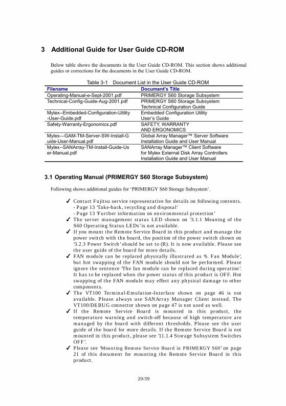
Fig. 3-a Removing the protection shield
- Remove the two screws near the rear side (1). - Pull out the protection shield in an angular position (2).
22/39
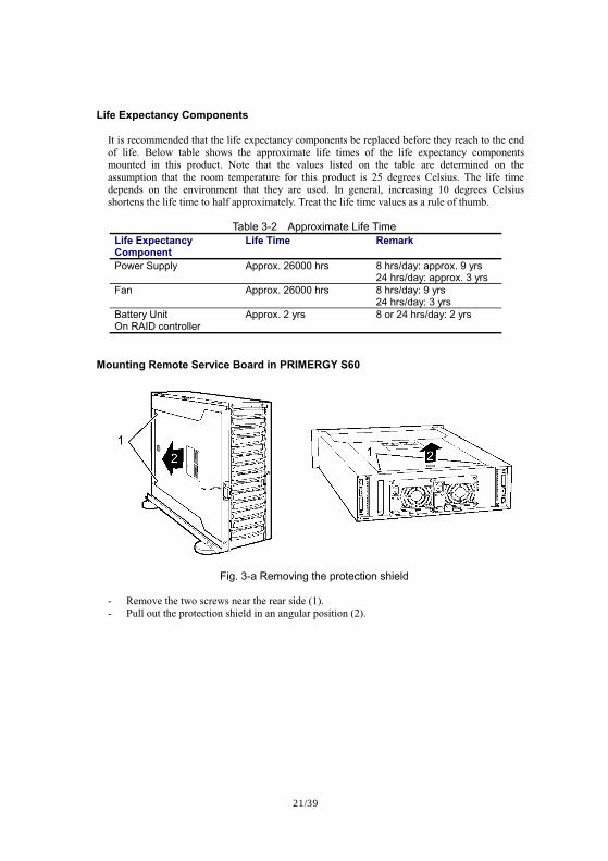
Fig. 3-b Removing the slot cover
- Loosen the fastening screw on the rear side of the storage subsystem. - Remove the slot cover.
Fig. 3-c Connecting the RSB cable
- Connect the RSB cable to the connector (RSB2) on the Remote Service Board.
23/39
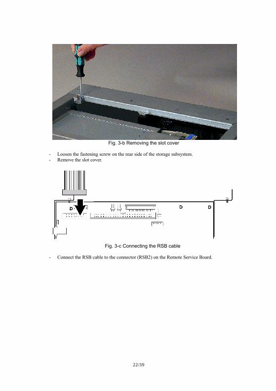
Fig. 3-d Inserting the RSB into the slot (1)
- Put the connected RSB module carefully into the storage subsystem directly placed
behind the HDD backplane.
Fig. 3-e Inserting the RSB into the slot (2)
- Push the RSB module carefully in direction of the rear side of the storage subsystem and
hang it in the existing mounting brackets.
24/39
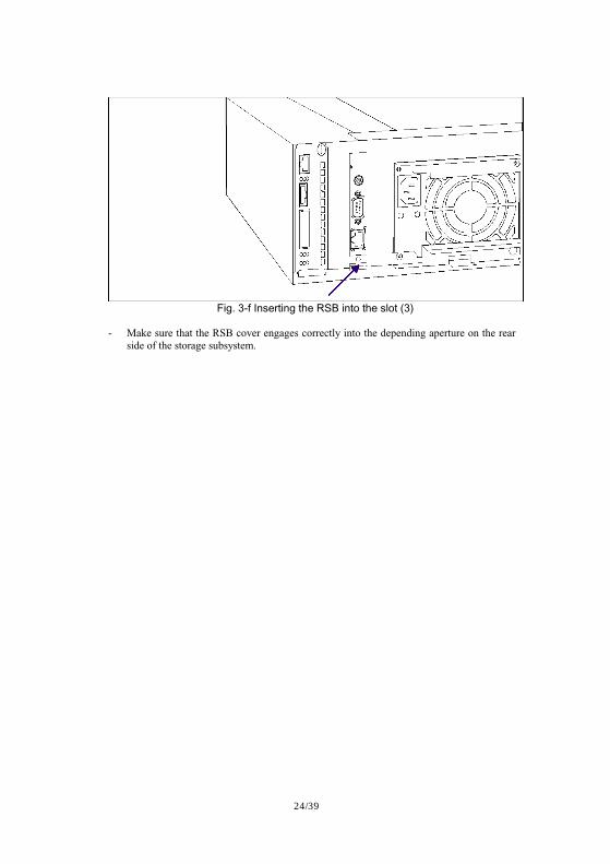
Fig. 3-f Inserting the RSB into the slot (3)
- Make sure that the RSB cover engages correctly into the depending aperture on the rear
side of the storage subsystem.
25/39
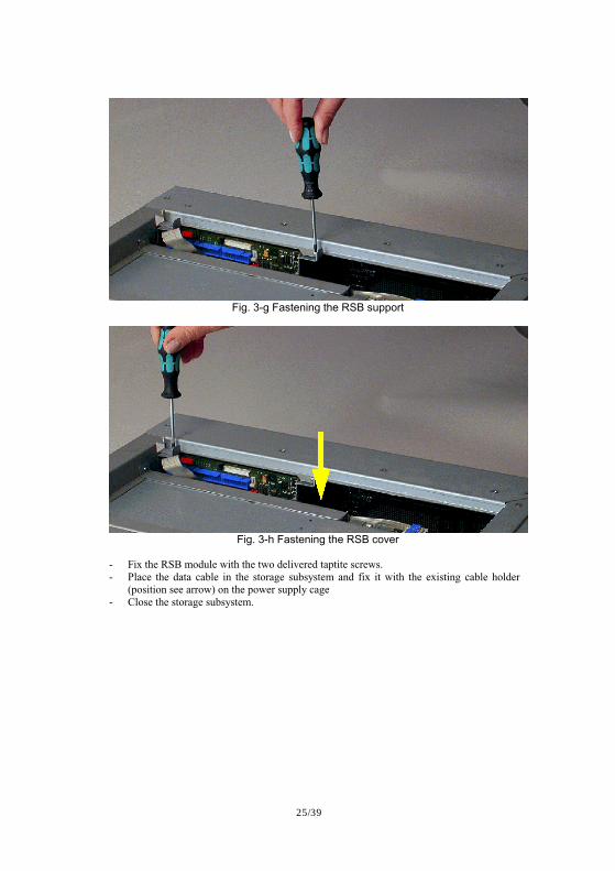
Fig. 3-g Fastening the RSB support
Fig. 3-h Fastening the RSB cover
- Fix the RSB module with the two delivered taptite screws. - Place the data cable in the storage subsystem and fix it with the existing cable holder
(position see arrow) on the power supply cage - Close the storage subsystem.
26/39
3.2 Technical Configuration Guide Following shows additional guides for ‘PRIMERGY S60 Storage Subsystem Technical Configuration Guide’.
#" The Embedded Configuration Utility shown on page 5 is not available. Please always use SANArray Manager Client instead. VT100-DEBUG port is not used as well.
#" Though the setting of ‘Enable Automatic Rebuild Management’ is shown as ‘Disabled’ on page 6, it has to be set to ‘Enabled’. The setting shown on page 8 and 11 is correct.
#" Though the setting of Controller 1 Port 0 is shown as ‘5’ on page 6 and 12, it may be ‘6’ depends on the configuration. Please see the section ‘Supported Configurations’ from page 27 of this document.
#" It is mentioned about Switch/Fabric configurations, Fujitsu does not support the configurations. The Connection Options in Extended Firmware Settings shown on page 54 should be always set to ‘0’ – Loop Only.
#" It is mentioned about MMF (Multi Mode Fibre) or SMF (Single Mode Fibre) on page 15 or after the page, Fujitsu does not support MMF. Fujitsu supports copper interface (HSSDC connector, up to 10m) only.
#" Though 16 configurations are shown from page 16 to page 47, Fujitsu supports 4 configurations shown on this document. Please see the section ‘Supported Configurations’ from page 27 of this document.
#" Though the setting of ‘Fibre-Topology’ is shown as ‘Multi Target ID’ on ‘3.3.3 Cluster with MultiPath’, it has to be set as ‘Multi-Port’ for the requirement of DDM MultiPath (PG-DAS1).
#" Fujitsu does not provide NVRAM file mentioned on page 49. Please set the QLA2200 configuration setting manually with Fast!UTIL as shown from page 51 to 54.
27/39
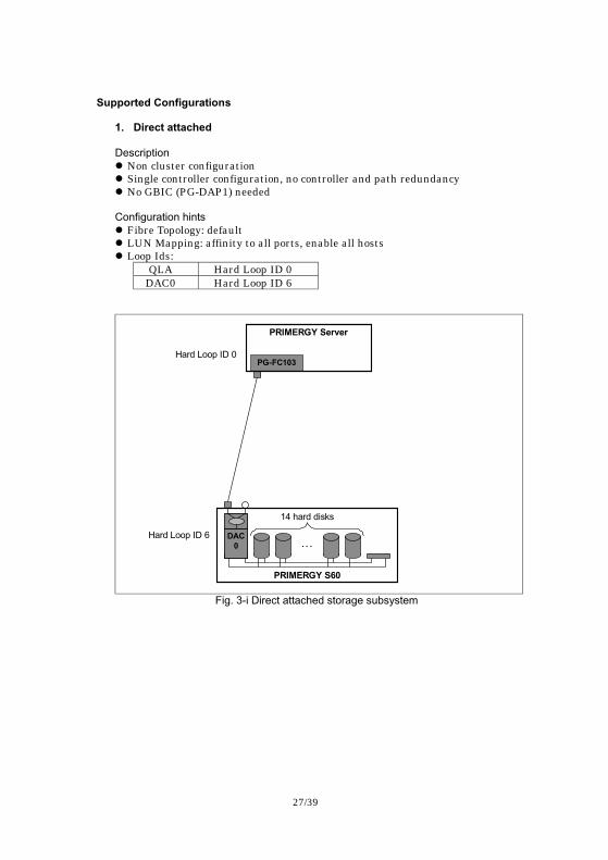
Supported Configurations 1. Direct attached Description #"Non cluster configuration #"Single controller configuration, no controller and path redundancy #"No GBIC (PG-DAP1) needed Configuration hints #"Fibre Topology: default #"LUN Mapping: affinity to all ports, enable all hosts #"Loop Ids:
QLA Hard Loop ID 0 DAC0 Hard Loop ID 6
Hard Loop ID 6
PRIMERGY Server
PG-FC103
PRIMERGY S60
. . .
14 hard disks
DAC 0
Hard Loop ID 0
Fig. 3-i Direct attached storage subsystem
28/39
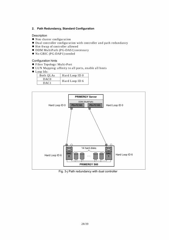
2. Path Redundancy, Standard Configuration Description #"Non cluster configuration #"Dual controller configuration with controller and path redundancy #"Hot-Swap of controller allowed #"DDM MultiPath (PG-DAS1) necessary #"No GBIC (PG-DAP1) needed Configuration hints #"Fibre Topology: Multi-Port #"LUN Mapping: affinity to all ports, enable all hosts #"Loop Ids:
Both QLAs Hard Loop ID 0 DAC0 DAC1 Hard Loop ID 6
PRIMERGY Server
DDM (MultiPath) PG-FC103 PG-FC103
PRIMERGY S60
. . .
14 hard disks
DAC 0
DAC 1 Hard Loop ID 6 Hard Loop ID 6
Hard Loop ID 0 Hard Loop ID 0
Fig. 3-j Path redundancy with dual controller
29/39
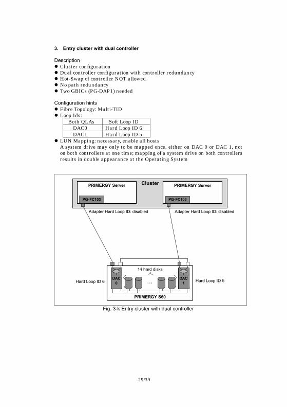
3. Entry cluster with dual controller Description #"Cluster configuration #"Dual controller configuration with controller redundancy #"Hot-Swap of controller NOT allowed #"No path redundancy #"Two GBICs (PG-DAP1) needed Configuration hints #"Fibre Topology: Multi-TID #"Loop Ids:
Both QLAs Soft Loop ID DAC0 Hard Loop ID 6 DAC1 Hard Loop ID 5
#"LUN Mapping: necessary, enable all hosts A system drive may only to be mapped once, either on DAC 0 or DAC 1, not on both controllers at one time; mapping of a system drive on both controllers results in double appearance at the Operating System
PRIMERGY S60
. . .
14 hard disks
DAC 0
DAC 1
Cluster PRIMERGY Server
PG-FC103
PRIMERGY Server
PG-FC103
Adapter Hard Loop ID: disabled
Hard Loop ID 6 Hard Loop ID 5
Adapter Hard Loop ID: disabled
Fig. 3-k Entry cluster with dual controller
30/39
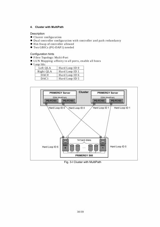
4. Cluster with MultiPath Description #"Cluster configuration #"Dual controller configuration with controller and path redundancy #"Hot-Swap of controller allowed #"Two GBICs (PG-DAP1) needed Configuration hints #"Fibre Topology: Multi-Port #"LUN Mapping: affinity to all ports, enable all hosts #"Loop Ids:
Left QLA Hard Loop ID 0 Right QLA Hard Loop ID 1
DAC0 Hard Loop ID 6 DAC1 Hard Loop ID 5
PRIMERGY Server
DDM (MultiPath) PG-FC103 PG-FC103
PRIMERGY Server
DDM (MultiPath) PG-FC103 PG-FC103
Cluster
DAC 1
DAC 0
PRIMERGY S60
. . .
14 hard disks
Hard Loop ID 6 Hard Loop ID 5
Hard Loop ID 0 Hard Loop ID 0 Hard Loop ID 1 Hard Loop ID 1
Fig. 3-l Cluster with MultiPath
31/39
3.3 Embedded Configuration Utility User’s Guide Fujitsu does not support the Embedded Configuration Utility. Please always use SANArray Manager Client and Server View instead for RAID management.
3.4 SAFETY, WARRANTY AND ERGONOMICS The following shows additional guides for ‘SAFTY, WARRANTY AND ERGONOMICS’.
#" Items mentioned from page 4 to page 9 are not applied to this product. Fujitsu offers different warranty from the items mentioned from page 4 to page 9 for customers. Please contact Fujitsu service representative for details.
3.5 GAM Server Software Installation Guide and User Manual
The following shows additional guides for ‘Global Array Manager™ Server Software Installation Guide and User Manual’.
#" The Global Array Manager Server software for Windows 2000 is not provided on the Software Kit CD-ROM. The software is provided on ServerStart CD-ROM. (P.4-1)
#" Create the setup floppy disks of Global Array Manager from the ServerStart CD-ROM and start Setup.exe in the floppy disk#1 to install Global Array Manager Server instead of clicking ‘Install Global Array Manager’. (P.4-3, Figure 4-1)
#"Never install ‘Workstation Array Manager’. It is not supported. (P.4-5, Figure 4-4)
#" Don’t install ‘Global Array Manager Client’ for PRIMERGY S60. The software is for Mylex PCI to SCSI RAID products. (P.4-5, Figure 4-4)
#" SNMP subcomponents are necessary. (P.4-6, Figure 4-5) #" Don’t install DMI. It is not supported. (P4-6, Figure 4-5)
3.6 SAM Client Software Installation Guide and User Manual
The following shows additional guides for ‘SANArray Manager� Client Software for Mylex External Disk Array Controllers Installation Guide and User Manual’.
#" Create the setup floppy disks of Global Array Manager from the ServerStart CD-ROM and start Setup.exe in the floppy disk#1 to install SANArray Manager Client instead of clicking ‘Install Global Array Manager’. (P.2-2, Figure 2-1)
#"Never install ‘Workstation Array Manager’. It is not supported. (P.2-4, Figure 2-3)
#" Don’t install ‘Global Array Manager Client’ for PRIMERGY S60. The software is for Mylex PCI to SCSI RAID products. (P.2-4, Figure 2-3)
#" “Settings” in Administration menu is not supported. Don’t use this function. (P.4-7, Figure 4-8)
#" Don’t use “Automatic Configuration” and “Assisted Configuration”. These are not supported. Please always use “Manual Configuration” instead to configure disk arrays. (P.4-39, Figure 4-34)
#" If you delete existing logical drives, a reboot is necessary to access
32/39
RAID controller via SAM Client. Otherwise the access capability may be disturbed because of plug-and-play feature of Windows 2000.
#" Don’t use “Edit Configuration” feature except in case of deleting existing logical drives. (P.4-52)
#" “Expand Array” function is NOT supported. Don’t use this function. (P.4-53)
#"Hard disk drives comprising a disk array (a physical pack) should be the same model, with the same storage capacity and rotational speed. (P.4-54)
#" The spare disk must also be the same model, with the same storage capacity and rotational speed as the other hard disks in the disk array (the physical pack). (P.4-55)
#" Don’t set different RAID levels for logical drives in the same physical pack. (P.4-55)
#" Always set “Stripe Size” to 64KB in logical drive definition. (P.4-56) #" “Kill Partner” and “Relinquish Partner” feature in “Controller
Information” window is NOT supported. Don’t use these functionalities. (P.5-11)
#" Don’t use “Force On Line” feature in “Logical Drive Information” window. This feature is NOT supported. (P.5-16)
#" “Show Bad Data Blocks” feature in “Logical Drive Information” window is NOT supported. (P.5-16)
#" Don’t cancel initialization, rebuilding and battery reconditioning process.
#" The “Enclosure Information” in Administration menu is not supported. This function cannot be used to monitor the enclosure. (P.5-17)
#" Don’t use the logical drive before the completion of the initialization. #" This product doesn’t support “Statistic View” in View menu. (P.5-23) #" The “Current Power” and “Maximum Power” values shown in
“Intelligent Battery Backup Unit” windows are only an approximate value. The values may differ from actual time due to battery degradation. (P.5-39)
4 Precaution
4.1 Log ‘Enclosure access critical’ on HDD Hot-Swap The following message may be logged when replacing the hard disk drive assigned at ID-0 or ID-1. Enclosure access critical. This log means one of two paths of enclosure monitoring is lost. Since the RAID controller(s) uses the path of ID-0 and ID-1 for enclosure monitoring, this status happens if the hard disk drive assigned at ID-0 or ID-1 is removed. If below message is logged after inserting the new hard disk drive, it is no problem. Enclosure access has been restored.
33/39
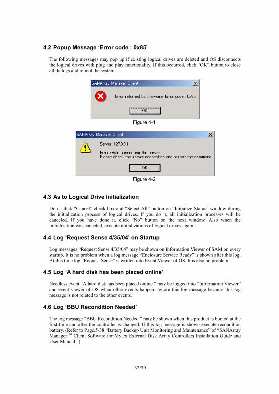
4.2 Popup Message ‘Error code : 0x85’ The following messages may pop up if existing logical drives are deleted and OS disconnects the logical drives with plug and play functionality. If this occurred, click “OK” button to close all dialogs and reboot the system.
Figure 4-1
Figure 4-2
4.3 As to Logical Drive Initialization Don’t click “Cancel” check box and “Select All” button on “Initialize Status” window during the initialization process of logical drives. If you do it, all initialization processes will be canceled. If you have done it, click “No” button on the next window. Also when the initialization was canceled, execute initializations of logical drives again.
4.4 Log ‘Request Sense 4/35/04’ on Startup Log messages “Request Sense 4/35/04” may be shown on Information Viewer of SAM on every startup. It is no problem when a log message “Enclosure Service Ready” is shown after this log. At this time log “Request Sense” is written into Event Viewer of OS. It is also no problem.
4.5 Log ‘A hard disk has been placed online’ Needless event “A hard disk has been placed online.” may be logged into “Information Viewer” and event viewer of OS when other events happen. Ignore this log message because this log message is not related to the other events.
4.6 Log ‘BBU Recondition Needed’ The log message “BBU Recondition Needed.” may be shown when this product is booted at the first time and after the controller is changed. If this log message is shown execute recondition battery. (Refer to Page.5-38 “Battery Backup Unit Monitoring and Maintenance” of “SANArray ManagerTM Client Software for Mylex External Disk Array Controllers Installation Guide and User Manual”.)
34/39
4.7 As to Controller View of SAM Physical device and logical drive icons of controller view window may not be updated automatically when these states are changed. (e.g. the case of changing state “Standby” to “Rebuilding”, etc.) Execute “Scan Devices” from “Administration” menu or re-start SAM client to update controller view in this case.
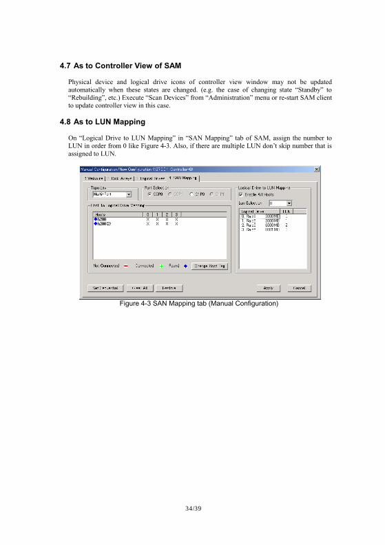
4.8 As to LUN Mapping On “Logical Drive to LUN Mapping” in “SAN Mapping” tab of SAM, assign the number to LUN in order from 0 like Figure 4-3. Also, if there are multiple LUN don’t skip number that is assigned to LUN.
Figure 4-3 SAN Mapping tab (Manual Configuration)
35/39
5 Miss-assignment of HDD Dead RAID controller may mark as Dead to incorrect ID of a hard disk drive, when a hard disk drive works abnormally during startup. Though this problem happens with very rare possibility, read this section for confirmation and follow the recovery procedure shown on this section if this problem happened. If the problem happens with the configuration in that no hot-spare drive is set, one power cycle is necessary to recover. With the configuration which includes a hot-spare drive, the recovery can be done without any power cycles. Since the problem only happens at the startup process, it does not happen with the subsystem that operates continuously for 24 hours a day.
5.1 Problem Isolation
Problem Isolation (1) (1) Since this problem happens because of a drive failure, SAM event 135
‘Logical drive is critical’ is reported same as a normal drive failure. (2) Look at SAM Controller view and HDD STATUS LED as usual. (3) Below table shows the difference between the normal drive failure and the
drive failure with this problem.
Table 5-1 Phenomena Difference Normal Drive Failure This Problem SAM Controller View The status of the ID
corresponding to the failed drive becomes ‘Dead’.
Without Hot-spare The ID that no drive exists physically becomes ‘Dead’. With Hot-spare No ID becomes ‘Dead’.
HDD STATUS LED The LED corresponding to the failed drive lights.
No LED shows a failed drive.
36/39
Problem Isolation (2)
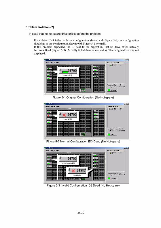
In case that no hot-spare drive exists before the problem If the drive ID-3 failed with the configuration shown with Figure 5-1, the configuration should go to the configuration shown with Figure 5-2 normally. If this problem happened, the ID next to the biggest ID that no drive exists actually becomes Dead (Figure 5-3). Actually failed drive is marked as ‘Unconfigured’ or it is not displayed.
������vw
Figure 5-1 Original Configuration (No Hot-spare)
����vw
Figure 5-2 Normal Configuration ID3 Dead (No Hot-spare)
������������vw
����vw
Figure 5-3 Invalid Configuration ID3 Dead (No Hot-spare)
37/39
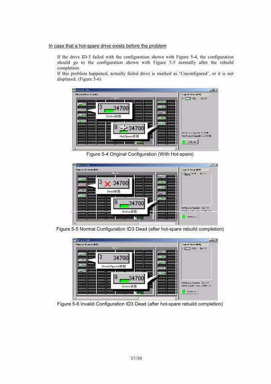
In case that a hot-spare drive exists before the problem If the drive ID-3 failed with the configuration shown with Figure 5-4, the configuration should go to the configuration shown with Figure 5-5 normally after the rebuild completion. If this problem happened, actually failed drive is marked as ‘Unconfigured’, or it is not displayed. (Figure 5-6)
������vw
��������vw
Figure 5-4 Original Configuration (With Hot-spare)
����vw
������vw
Figure 5-5 Normal Configuration ID3 Dead (after hot-spare rebuild completion)
������������vw
������vw
Figure 5-6 Invalid Configuration ID3 Dead (after hot-spare rebuild completion)
38/39
5.2 Recovery
No hot-spare drive exists before the problem Actually failed drive is marked as Unconfigured, or it is not displayed. Wrong location that no drive exists actually is marked as Dead. 1. Ensure that Dead is marked at the ID that actually no drive exists, with SAM
Client Controller View.
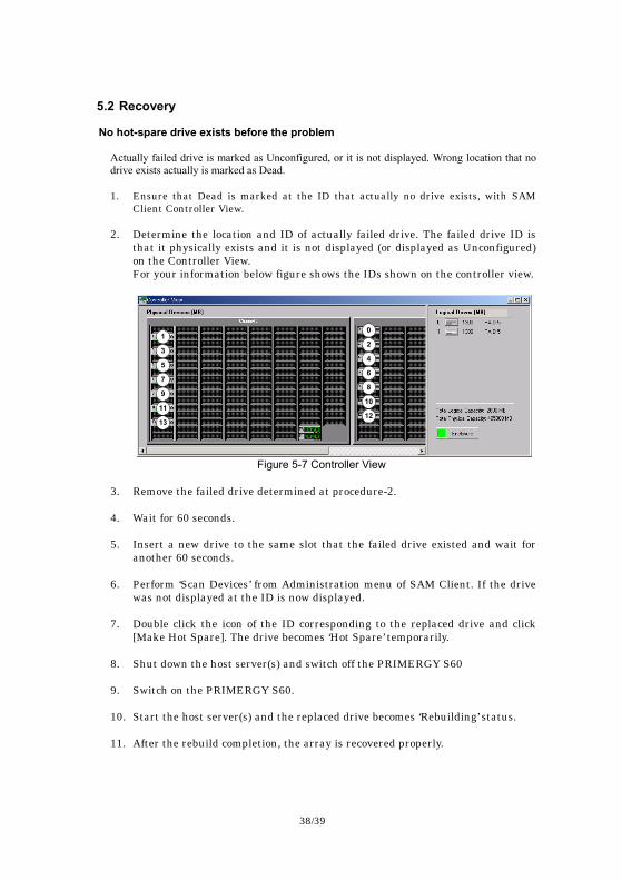
2. Determine the location and ID of actually failed drive. The failed drive ID is that it physically exists and it is not displayed (or displayed as Unconfigured) on the Controller View. For your information below figure shows the IDs shown on the controller view.
1
3
5
7
9
11
13
0
2
4
6
8
10
12
Figure 5-7 Controller View
3. Remove the failed drive determined at procedure-2.
4. Wait for 60 seconds.
5. Insert a new drive to the same slot that the failed drive existed and wait for
another 60 seconds.
6. Perform ‘Scan Devices’ from Administration menu of SAM Client. If the drive was not displayed at the ID is now displayed.
7. Double click the icon of the ID corresponding to the replaced drive and click [Make Hot Spare]. The drive becomes ‘Hot Spare’ temporarily.
8. Shut down the host server(s) and switch off the PRIMERGY S60
9. Switch on the PRIMERGY S60.
10. Start the host server(s) and the replaced drive becomes ‘Rebuilding’ status.
11. After the rebuild completion, the array is recovered properly.
39/39
A hot-spare drive exists before the problem Actually failed drive is marked as Unconfigured, or it is not displayed. 1. Ensure that the rebuild is completed automatically with SAM Client Controler
View and SAM log.
2. Determine the location and ID of actually failed drive. The failed drive ID is that it physically exists and it is not displayed (or displayed as Unconfigured) on the Controller View. For your information Figure 5-7 shows the IDs shown on the controller view.
3. Remove the failed drive determined at procedure-2.
4. Wait for 60 seconds.
5. Insert a new drive to the same slot that the failed drive existed and wait for another 60 seconds.
6. Perform ‘Scan Devices’ from Administration menu of SAM Client. If the drive was not displayed at the ID is now displayed.
7. Double click the icon of the ID corresponding to the replaced drive and click [Make Hot Spare]. The drive becomes ‘Hot Spare’. Then the array is recovered.
“Microsoft”, “Windows” and “Windows NT” are registered trademarks of Microsoft Corporation, U.S.A. in the United States and other countries. “SANArray Manager” and “Global Array Manager” are trademarks of Mylex Corporation, U.S.A.


![PRIMERGY BX620 S4 (Xeon® X5355 / E5310 / 5160 …...2007/05/14 · PRIMERGY BX620 S4 (Xeon® X5355 / E5310 / 5160 / 5130 / 5110 搭載タイプ) [A-1] PRIMERGY BX620 S4 サーバブレード](https://img.pdfslide.tips/doc/110x75/5f22fbfe212d1d184b19d6c3/primergy-bx620-s4-xeon-x5355-e5310-5160-20070514-primergy-bx620.jpg)