Embed Size (px)
Citation preview
B
B-108
Proceedings of the 9th
Domain-Specific Modeling(DSM´09)
OOPSLA Workshop on
Matti RossiJonathan Sprinkle
Matti R
ossi, Jonathan Sprinkle, Jeff Gray, Juha-Pekka Tolvanen (eds.):
Proceedings of the 9th OO
PSLA W
orkshop on Dom
ain-Specific Modeling (D
SM’09)
B-108
B-108
Jeff GrayJuha-Pekka Tolvanen (eds.)
HELSINGIN KAUPPAKORKEAKOULUN
JULKAISUJA
B-108
Matti Rossi, Jonathan Sprinkle, Jeff Gray, Juha-Pekka Tolvanen (eds.)
Proceedings of the 9th OOPSLA Workshop onDomain-Specific Modeling
(DSM’09)

© Matti Rossi, Jonathan Sprinkle, Jeff Gray, Juha-Pekka Tolvanen (eds.) and Helsingin kauppakorkeakoulu
ISSN 0356-889XISBN 978-952-488-371-9
E-versio:
ISBN 978-952-488-372-6
Helsingin kauppakorkeakoulu - HSE Print 2009

Welcome to the 9th Workshop on Domain-Specific Modeling Workshop – DSM’09
Preface
Domain-Specific Modeling (DSM) is continuing to receive interest among the general software engineering community. As an example, the special issue of IEEE Software (July/August 2009) gave the approach much needed visibility. Several controlled experiments have shown that DSMs are more productive than general model based approaches. As Booch et al. have stated, “the full value of MDA is only achieved when the modeling concepts map directly to domain concepts rather than computer technology concepts.” For example, DSM for cell phone software would have concepts like “Soft key button,” “SMS” and “Ring tone,” and generators to create calls to the corresponding code components.
Continued investigation is still needed in order to advance the acceptance and viability of DSM. This workshop, which is in its ninth incarnation at OOPSLA 2009, features research and experience papers describing new ideas at either a practical or theoretical level. On the practical side, several papers in these proceedings describe application of modeling techniques within a specific domain. As in previous workshops, there are plenty of language examples contributed to these proceedings.
We have organized the 18 papers in these proceedings to emphasize general areas of interest into which the papers loosely fit. Authors from both industry and academia have contributed research ideas that initiate and forward the technical underpinnings of domain-specific modeling. The papers in this proceedings are categorized into the areas of Language Design, Language Examples, DSLs for the web, Transformations and Language Evolution, Model Verification and Testing and Special Topics. Many papers in these proceedings are cross-cutting in their analysis and reporting. As a whole, the body of work highlights the importance of metamodeling and related tooling, which significantly ease the implementation of domain-specific languages and provide support for experimenting with the modeling language as it is built (thus, metamodel-based language definition also assists in the task of constructing generators that reduce the burden of tool creation and maintenance). We hope that you will enjoy this record of the workshop and find the information within these proceedings valuable toward your understanding of the current state-of-the-art in Domain-Specific Modeling.
Matti Rossi, Jonathan Sprinkle, Jeff Gray, Juha-Pekka Tolvanen
October 2009 Orlando, Florida

9th WORKSHOP ON DOMAIN-SPECIFIC MODELING
25-26 October 2009, Orlando, USA
Program Committee
Pierre America, Philips Robert Baillargeon, Panasonic Automotive Systems, USA Krishnakumar Balasubramanian, The MathWorks Inc. Peter Bell, SystemsForge Jorn Bettin, Sofismo Philip T. Cox, Dalhousie University Krzysztof Czarnecki, University of Waterloo Brandon Eames, Utah State University Robert France, Colorado State University Ethan Jackson, Microsoft Frederic Jouault, AtlanMod (INRIA & EMN) Jürgen Jung, Deutsche Post Steven Kelly, MetaCase Gunther Lenz, Microsoft Shih-Hsi Liu, California State University, Fresno Kalle Lyytinen, Case Western Reserve University Juha Pärssinen, VTT Arturo Sanchez, Univ of North Florida Jun Suzuki, University of Massachusetts, Boston Markus Völter, independent consultant Jos Warmer, Ordina Jing Zhang, Motorola Research
Organizing Committee
Juha-Pekka Tolvanen, MetaCase Jeff Gray, University of Alabama at Birmingham Matti Rossi, Helsinki School of Economics Jonathan Sprinkle, University of Arizona

Table of Contents Welcome message from the organizers List of program and organizing committees
Language Design
Design Guidelines for Domain-Specific Languages Gabor Karsai, Holger Krahn, Claas Pinkernell, Bernhard Rumpe, Martin Schindler, and Steven Völkel
7
Evaluating the Use of Domain-Specific Modeling in Practice Juha Kärnä, Juha-Pekka Tolvanen and Steven Kelly
14
Multi-Language Development of Embedded Systems Thomas Kuhn, Soeren Kemmann, Mario Trapp and Christian Schäfer
21
Language Examples
ITML : A Domain-Specific Modeling Language for Supporting Business Driven IT Management
Ulrich Frank, David Heise, Heiko Kattenstroth, Donald F. Ferguson, Ethan Hadar and Marvin G. Waschke
28
Domain Specific Languages for Business Process Management: a Case Study Janis Barzdins, Karlis Cerans, Mikus Grasmanis, Audris Kalnins, Sergejs Kozlovics, Lelde Lace, Renars Liepins, Edgars Rencis, Arturs Sprogis and Andris Zarins
36
Use of a Domain Specific Modeling Language for Realizing Versatile Dashboards Ulrich Frank, David Heise and Heiko Kattenstroth
43
DSML-Aided Development for Mobile P2P Systems Tihamer Levendovszky, Tamás Mészáros, Péter Ekler and Mark Asztalos
51
DSLs for the Web
MobiDSL - a Domain Specific Language for Mobile Web : developing applications for mobile platform without web programming
Ankita Arvind Kejriwal and Mangesh Bedekar
57
MontiWeb - Modular Development of Web Information Systems Michael Dukaczewski, Dirk Reiss, Bernhard Rumpe and Mark Stein
64
ProcDSL + ProcEd - a Web-based Editing Solution for Domain Specific Process-Engineering
Christian Berger, Tim Gülke and Bernhard Rumpe
70
Transformations and Language Evolution
Model-View-Controller Architecture Specific Model Transformation Hiroshi Kazato, Rafael Weiss, Shinpei Hayashi, Takashi Kobayashi and Motoshi Saeki
75
Evolution of a Domain Specific Language and its engineering environment - Lehman’s laws revisited
Mika Karaila
81
Automatic Domain Model Migration to Manage Metamodel Evolution Daniel Balasubramanian, Tihamer Levendovszky, Anantha Narayanan and Gabor Karsai
88

Model Verification and Testing
Using Model-Based Testing for Testing Application Models in the Context of Domain-Specific Modelling
Janne Merilinna and Olli-Pekka Puolitaival
95
Right or Wrong? – Verification of Model Transformations using Colored Petri Nets Manuel Wimmer, Gerti Kappel, Angelika Kusel, Werner Retschitzegger, Johannes Schoenboeck and Wieland Schwinger
101
A Tooling Environment for Quality-Driven Model-Based Software Development Janne Merilinna and Tomi Räty
107
Special Topics
Towards a Generic Layout Composition Framework for Domain-Speci c Models Jendrik Johannes and Karsten Gaul
113
Model-Based Autosynthesis of Time-Triggered Buffers for Event-Based Middleware Systems
Jonathan Sprinkle and Brandon Eames
119

Design Guidelines for Domain Specific Languages
Gabor KarsaiInstitute for SoftwareIntegrated SystemsVanderbilt University
Nashville, USA
Holger KrahnSoftware Engineering Group
Department of ComputerScience
RWTH Aachen, Germany
Claas PinkernellSoftware Engineering Group
Department of ComputerScience
RWTH Aachen, Germany
Bernhard RumpeSoftware Engineering Group
Department of ComputerScience
RWTH Aachen, Germany
Martin SchindlerSoftware Engineering Group
Department of ComputerScience
RWTH Aachen, Germany
Steven VölkelSoftware Engineering Group
Department of ComputerScience
RWTH Aachen, Germany
ABSTRACTDesigning a new domain specific language is as any othercomplex task sometimes error-prone and usually time con-suming, especially if the language shall be of high-qualityand comfortably usable. Existing tool support focuses onthe simplification of technical aspects but lacks support foran enforcement of principles for a good language design. Inthis paper we investigate guidelines that are useful for de-signing domain specific languages, largely based on our ex-perience in developing languages as well as relying on ex-isting guidelines on general purpose (GPLs) and modelinglanguages. We defined guidelines to support a DSL devel-oper to achieve better quality of the language design and abetter acceptance among its users.
1. INTRODUCTIONDesigning a new language that allows us to model new
technical properties in a simpler and easier way, describe orimplement solutions, or to describe the problem resp. re-quirements in a more concise way is one of the core chal-lenges of computer science. The creation of a new languageis a time consuming task, needs experience and is thus usu-ally carried out by specialized language engineers. Nowa-days, the need for new languages for various growing do-mains is strongly increasing. Fortunately, also more sophis-ticated tools exist that allow software engineers to define anew language with a reasonable effort. As a result, an in-creasing number of DSLs (Domain Specific Languages) aredesigned to enhance the productivity of developers withinspecific domains. However, these languages often fit onlyto a rather specific domain problem and are neither of thequality that they can be used by many people nor flexibleenough to be easily adapted for related domains.
During the last years, we developed the frameworks Mon-tiCore [13] and GME [2] which support the definition ofdomain specific languages. Using these frameworks we de-signed several DSLs for a variety of domains, e.g., a textualversion of UML/P notations [17] and a language based onfunction nets in the automotive domain [5]. We experiencedthat the design of a new DSL is a difficult task because dif-ferent people have a varying perception of what a “good”language actually is.
This of course also depends on the taste of the developerrespectively the users, but there are a number of generallyacceptable guidelines that assist in language development,making it more a systematic, methodological task and lessan intellectual ad-hoc challenge. In this paper we summa-rize, categorize, and amend existing guidelines as well asadd our new ones assuming that they improve design andusability of future DSLs.
In the following we present general guidelines to be consid-ered for both textual and graphical DSLs with main focus ison the former. The guidelines are discussed sometimes usingexamples from well-known programming languages or math-ematics, because these languages are known best. Depend-ing on the concrete language and the domain these guidelineshave to be weighted differently as there might be differentpurposes, complexity, and number of users of the resultinglanguage. For example, for a rather simple configurationlanguage used in only one project a timely realization is usu-ally more important than the optimization of its usability.Therefore, guidelines must be sometimes ignored, altered, orenforced. Especially quality-assurance guidelines can resultin an increased amount of work.
While we generally focus in our work on DSLs that arespecifically dedicated to modeling aspects of (software) sys-tems, we believe that these guidelines generally hold for anyDSL that embeds a certain degree of complexity.
1.1 Literature on Language DesignFor programming languages, design guidelines have been
intensively discussed since the early 70s. Hoare [8] intro-duced simplicity, security, fast translation, efficient objectcode, and readability as general criteria for the design ofgood languages. Furthermore, Wirth [22] discussed sev-eral guidelines for the design of languages and correspond-ing compilers. The rationale behind most of the guidelinesand hints of both articles can be accepted as still valid to-day, but the technical constraints have changed dramati-cally since the 70s. First of all, computer power has in-creased significantly. Therefore, speed and space problemshave become less important. Furthermore, due to sophis-ticated tools (e.g., parser generators) the implementationof accompanying tools is often not a necessary part of thelanguage development any more. Of course, both articles
7 7
concentrate on programming languages and do not considerthe greater variety of domain specific languages.
More recently, authors have also discussed the design ofdomain specific modeling languages. General principles formodeling language design were introduced in [14]. Theseinclude simplicity, uniqueness, consistency, and scalability,on which we will rely later. However, the authors did notdiscuss how these higher level principles can be achieved.In [12] certain aspects of the DSL development are explainedand some guidelines are introduced. More practical guide-lines for implementing DSLs are given in [10]. These focuson how to identify the necessary language constructs to gen-erate full code from models. The authors explain how toprovide tool support with the MetaEdit+ environment. [20]explains 12 lessons learned from DSL experiments that canhelp to improve a DSL. Although more detailed discussionson explicit guidelines are missing, these lessons embed doc-umented empirical evidence – a documentation that manyother discussions, including ours do not have. In [16] theauthors introduce a toolset which supports the definitionof DSLs by checking their consistency with respect to sev-eral objectives. Language designers can select properties oftheir DSL to be developed and the system automaticallyderives other design decisions in order to gain a consistentlanguage definition. However, the introduced criteria coveronly a subset of the decisions to be made and hence, cannotserve as the only criteria for good language design. Quitethe contrary, to our experience many design guidelines can-not be translated in automatic measures and thus cannot bechecked by a tool.
1.2 Categories of DSL Design GuidelinesThe various design guidelines we will discuss below, can
be organized into several categories. Essentially, these guide-lines describe techniques that are useful at different activitiesof the language development process, which range from thedomain analysis to questions of how to realize the DSL to thedevelopment of an abstract and a concrete syntax includingthe definition of context conditions. An alignment of guide-lines with the language development activities and the de-veloped artifacts has the advantage that a language designercan concentrate on the respective subset of the guidelines ateach activity. This should help identifying and realizing thedesired guidelines. Therefore, we decided for a developmentphase oriented classification and identified the following cat-egories:
Language Purpose discusses design guidelines for the earlyactivities of the language development process.
Language Realization introduces guidelines which discusshow to implement the language.
Language Content contains guidelines which focus on theelements of a language.
Concrete Syntax concentrates on design guidelines for thereadable (external) representation of a language.
Abstract Syntax concentrates on design guidelines for theinternal representation of a language.
For each of these categories we will discuss the designguidelines we found useful. Please be aware that the subse-quently discussed guidelines sometimes are in conflict with
each other and the language developer sometimes has to bal-ance them accordingly. Additionally, semantics is explicitlynot listed as a separate step as it should be part of the entiredevelopment process and therefore has an influence on all ofthe categories above.
2. DSL DESIGN GUIDELINES
2.1 Language PurposeLanguage design is not only influenced by the question of
what it needs to describe, but equally important what to dowith the language. Therefore, one of the first activities inlanguage design is to analyze the aim of the language.
Guideline 1: “Identify language uses early.” The languagedefined will be used for at least one task. Most commonuses are: documentation of knowledge (only) and code ge-neration. However, there are a lot more forms of usage:definition or generation of tests, formal verification, auto-matic analysis of various kinds, configuration of the systemat deployment- or run-time, and last but increasingly im-portant, simulation.
An early identification of the language uses have strong in-fluence on the concepts the language will allow to offer. Codegeneration for example is not generally feasible when thelanguage embeds concepts of underspecification (e.g., non-deterministic Statecharts). Even if everything is designed tobe executable, there are big differences regarding the over-head necessary to run certain kinds of models. If efficientexecution on a small target machine is necessary (e.g., mo-bile or car control device) then high-level concepts must bedesigned for optimized code generations. For simulation andvalidation of requirements however, efficiency plays a minorrole.
Guideline 2: “Ask questions.” Once the uses of a languagehave been identified it is helpful to embed these forms oflanguage uses into the overall software development process.People/roles have to be identified that develop, review, anddeploy the involved programs and models. The followingquestions are helpful for determining the necessary decisions:Who is going to model in the DSL? Who is going to reviewthe models? When? Who is using the models for whichpurpose?
Based thereon, the question after whether the language istoo complex or captures all the necessary domain elementscan be revisited. In particular, appropriate tutorials for theDSL users in their respective development process shouldnow be prepared.
Guideline 3: “Make your language consistent.” DSLs aretypically designed for a specific purpose. Therefore, eachfeature of a language should contribute to this purpose, oth-erwise it should be omitted. As an illustrative example weconsider a platform independent modeling language. In thislanguage, all features should be platform independent aswell. This design principle was already discussed in [14].
2.2 Language RealizationWhen starting to define a new language, there are severaloptions on how to realize it. One can implement the DSLfrom scratch or reuse and extend or reduce an existing lan-guage, one can use a graphical or a textual representation,
8 8

and so on. We have identified general hints which have tobe taken into account for these decisions.
Guideline 4: “Decide carefully whether to use graphical ortextual realization.” Nowadays, it is common to use toolssupporting the design of graphical DSLs such as the EclipseModeling Framework (EMF) or MetaEdit+. On the otherhand, there exist sophisticated tools and frameworks likeMontiCore or xText for text-based modeling. As describedin [6], there are a number of advantages and disadvantagesfor both approaches. Textual representations for exampleusually have the advantage of faster development and areplatform and tool independent whereas graphical modelsprovide a better overview and ease the understanding ofmodels. Therefore, advantages and disadvantages have tobe weighted and matched against end users’ preferences inorder to make a substantiated decision for one of the real-izations. From this point on, a more informed decision canbe made for a concrete tool to realize the language basedon their particular features and the intended use of the lan-guage. Comparisons can be found in [21] or [3].
Guideline 5: “Compose existing languages where possible.”The development of a new language and an accompanyingtoolset is a labor-intensive task. However, it is often thecase that existing languages can be reused, sometimes evenwithout adaptation. A good example for language reuseis OCL: it can be embedded in other languages in orderto define constraints on elements expressed in the hostinglanguage.
The most general and useful form of language reuse is thusthe unchanged embedding of an existing language into an-other language. A more sophisticated approach is to havepredefined holes in a host language, such that the defini-tion of a new language basically consists of a compositionof different languages. For textual languages this composi-tional style of language definitions is well understood andsupported by sophisticated tools such as [11] which also as-sists the composition of appropriate tools.
However, according to the seamlessness principle [14], theconcepts of the languages to be composed need to fit to-gether. In the UML, the object oriented paradigm under-lies both class diagrams and Statecharts which therefore fitwell together. Additionally, when composing languages caremust be exercised to avoid confusion: similar constructs withdifferent semantics should be avoided.
Guideline 6: “Reuse existing language definitions.” If thelanguage cannot be simply composed from some given lan-guage parts, e.g., by language embedding as proposed inguideline 5, it is still a good idea to reuse existing languagedefinitions as much as possible. In [18] more possible real-ization strategies, such as language extension or languagespecialization are analyzed. This means, taking the defini-tion of a language as a starter to develop a new one is betterthan creating a language from scratch. Both the concreteand the abstract syntax will benefit from this form of reuse.The new language then might retain a look-and-feel of theoriginal, thus allowing the user to easily identify familiarnotations. Looking at the abstract syntax of existing lan-guages, one can identify “language pattern” (quite similarto design pattern), which are good guidelines for languagedesign. For example, expressions, primary expressions, orstatements have quite a common pattern in all languages.
Only if there is no existing language/notation or the disad-vantages do not allow using the strategies mentioned above,a standalone realization should be considered. The websitesof parser generators like Antlr [1] or Atlantic Zoo [19] are agood starting point for reusing language definitions.
Guideline 7: “Reuse existing type systems.” A DSL usedfor software development often comprises and even extendseither a property language such as OCL or an implementa-tion language such as Java. As described in [8], the designof a type system for such a language is one of the hardesttasks because of the complex correlations of name spaces,generic types, type conversions, and polymorphism.
Furthermore, an unconventional type system would behard for users to adopt as well. Therefore, a language de-signer should reuse existing type systems to improve com-prehensibility and to avoid errors that are caused by misin-terpretations in an implementation. Furthermore, it is farmore economical to use an existing type system, than devel-oping a new one as this is a labor intensive and error-pronetask. A well-documented object-oriented type system canbe tailored to the needs of the DSL or even an implementedreusable type system can be used (e.g. [4]).
2.3 Language ContentOne main activity in language development is the task ofdefining the different elements of the language. Obviously,we cannot define in general which elements should be partof a language as this typically depends on the intended use.However, the decisions can be guided by some basic hintswe propose in this Section.
Guideline 8: “Reflect only the necessary domain concepts.”Any language shall capture a certain set of domain artifacts.These domain artifacts and their essential properties needto be reflected appropriately in the language in a way thatthe language user is able to express all necessary domainconcepts. To ensure this, it is helpful to define a few modelsearly to show how such a reflection would look like. Thesemodels are a good basis for feedback from domain expertswhich helps the developer to validate the language definitionagainst the domain. However, when designing a languagenot all domain concepts need to be reflected, but only thosethat contribute to the tasks the language shall be used for.
Guideline 9: “Keep it simple.” Simplicity is a well knowncriterion which enhances the understandability of a language[8, 14, 22]. The demand for simplicity has several rea-sons. First, introducing a new language in a domain pro-duces work in developing new tools and adapting existingprocesses. If the language itself is complex, it is usuallyharder to understand and thus raises the barrier of intro-ducing the language. Second, even when such a language issuccessfully introduced in a domain, unnecessary complexitystill minimizes the benefit the language should have yielded.Therefore, simplicity is one of the main targets in designinglanguages. The following more detailed Guidelines 10, 11,and 12 will show how to achieve simplicity.
Guideline 10: “Avoid unnecessary generality.” Usually, adomain has a finite collection of concepts that should bereflected in the language design. Statements like “maybewe can generalize or parameterize this concept for futurechanges in the domain” should be avoided as they unneces-
9 9
sarily complicate the language and hinder a quick and suc-cessful introduction of the DSL in the domain. Therefore,this guideline can also be defined as “design only what isnecessary”.
Guideline 11: “Limit the number of language elements.” Alanguage which has several hundreds of elements is obviouslyhard to understand. One approach to limit the number ofelements in a language for complex domains is to designsublanguages which cover different aspects of the systems.This concept is, e.g., employed by the UML: different kindsof diagrams are used for special purposes such as structure,behavior, or deployment. Each of them has its own notationwith a limited number of concepts.
A further possibility to limit the number of elements ofa language is to use libraries that contain more elaboratedconcepts based on the concepts of the basic language andthat can be reused in other models. Elements which werepreviously defined as part of the language itself can thenbe moved to a model in the library (compare, e.g., I/O inPascal vs. C++). Furthermore, users can extend a libraryby their own definitions and thus, can add more and morefunctionality without changing the language structure itself.Therefore, introducing a library leads to a flexible, extensi-ble, and extensive language that nevertheless is kept simple.On the other hand, a language capable of library importand definition of those elements must have a number of ap-propriate concepts embedded to enable this (e.g., methodand class definitions, modularity, interfaces - whatever thismeans in the DSL under construction). This principle hassuccessfully been applied in GPL design where the languagesare usually small compared to their huge standard libraries.
Guideline 12: “Avoid conceptual redundancy.” Redun-dancy is a constant source of problems. Having several con-cepts at hand to describe the same fact allows users to modelit differently. The case of conceptual richness in C++ showsthat coding guidelines then usually forbid a number of con-cepts. E.g., the concept of classes and structs is nearly iden-tical, the main difference is the default access of memberswhich is public for structs and private for classes. There-fore, classes and structs can be used interchangeably withinC++ whereas the slight difference might be easily forgot-ten. So, it should be generally avoided to add redundantconcepts to a language.
Guideline 13: “Avoid inefficient language elements.” Onemain target of domain specific modeling is to raise the levelof abstraction. Therefore, the main artifacts users deal withare the input models and not the generated code. On theother hand, the generated code is necessary to run the finalsystem and more important, the generated code determinessignificant properties of the system such as efficiency. Hence,the language developer should try to generate efficient code.
Furthermore, efficiency of a model should be transparentto the language user and therefore should only depend onthe model itself and not on specific elements used withinthe model. Elements which would lead to inefficient codeshould be avoided already during language design so thatonly the language user is able to introduce inefficiency [8].For example, in Java there is no operator to get all instancesof one class as this would increase memory usage and oper-ating time significantly. However, this functionality can beimplemented by a Java user if needed.
2.4 Concrete SyntaxConcrete syntax has to be chosen well in order to have anunderstandable, well structured language. Thus, we con-centrate on the concrete syntax first and will deal with theabstract syntax later.
Guideline 14: “Adopt existing notations domain expertsuse.” As [20] says, it is generally useful to adopt what-ever formal notation the domain experts already have, ratherthan inventing a new one.
Computer experts and especially language designers areusually very practiced in learning new languages. On thecontrary, domain experts often use a language for a longertime and do not want to learn a new concrete syntax es-pecially when they already have a notation for a certainproblem. As already mentioned, it is often the case that theintroduction of a DSL makes new tools and modified pro-cesses necessary. Inventing a new concrete syntax for givenconcepts would raise the barrier for domain experts. Thus,existing notations should be adopted as much as possible.E.g., queries within the database domain should be definedwith SQL instead of inventing a new query language. Evenif queries are only part of a new language to be defined SQLcould be embedded within the new language.
In case a suitable notation does not already exist, the newlanguage should be adopted as close as possible to otherexisting notations within the domain or to other commonused languages. A good example for commonly acceptedlanguages are mathematical notations like arithmetical ex-pressions [8].
Guideline 15: “Use descriptive notations.” A descriptivenotation supports both learnability and comprehensibilityof a language especially when reusing frequently-used termsand symbols of domain or general knowledge. To avoid mis-interpretation it is highly important to maintain the seman-tics of these reused elements. For instance, the sign “+”usually stands for addition or at least something seman-tically similar to that whereas commas or semicolons areinterpreted as separators. This applies to keywords witha widely-accepted meaning as well. Furthermore, keywordsshould be easily identifiable. It is helpful to restrict the num-ber of keywords to a few memorizable ones and of course, tohave a keyword-sensitive editor.
A good example for a descriptive notation is the way howspecial character like Greek letters are expressed in Latex.Instead of using a Unicode-notation each letter can be ex-pressed by its name (\alpha for α, \beta for β, and so on).
Guideline 16: “Make elements distinguishable.” Easily dis-tinguishable representations of language elements are a ba-sic requirement to support understandability. In graphicalDSLs, different model elements should have representationsthat exhibit enough syntactic differences to be easily dis-tinguishable. Different colors as the only criteria may becounterproductive, e.g., when printed in black and white. Intextual languages usually keywords are used in order to sep-arate kinds of elements. These keywords have to be placedin appropriate positions of the concrete syntax, as other-wise readers need to start backtracking when “parsing” thetext [8, 22]. The absence of keywords is often based on effi-ciency for the writer. But this is a very weak reason becausemodels are much more often read than written and thereforeto be designed from a readers point of view.
10 10

Guideline 17: “Use syntactic sugar appropriately.” Lan-guages typically offer syntactic sugar, i.e., elements which donot contribute to the expressiveness of the language. Syn-tactic sugar mainly serves to improve readability, but tosome extent also helps the parser to parse effectively. Key-words chosen wisely help to make text readable. Generally,if an efficient parser cannot be implemented, the languageis probably also hard to understand for human readers.
However, an overuse of the addition of syntactic sugar dis-tracts, because verbosity hinders to see the important con-tent directly. Furthermore, it should be kept in mind thatseveral forms of syntactic sugar for one concept may hindercommunication as different persons might prefer differentelements for expressing the same idea.
Nevertheless the introduction of syntactic sugar can alsoimprove a language, e.g., the enhanced for-statement in Java5 is widely accepted although it is conceptually redundant toa common for-statement. This is a conflict to guideline 12,but the frequency of occurrence of common for-statements inJava legitimates a more effective alternative of this notation.
Guideline 18: “Permit comments.” Comments on modelelements are essential for explaining design decisions madefor other developers. This makes models more understand-able and simplifies or even enables collaborative work. Soa widely accepted standard form of grouped comments, like/* ... */, and line comments, like // ... for textuallanguages or text boxes and tooltips for graphical languagesshould be embedded.
Furthermore, specially structured comments can be usedfor further documentation purposes as generating HTML-pages like Javadoc. In [8] it is mentioned that the “purposeof a programming language is to assist in the documenta-tion of programs”. Therefore we recommend that every DSLshould allow a user to generally comment at various partsof the model. If desired, the language may even contain thedefinition of a comment structure directly, thus enforcing acertain style of documentation.
Guideline 19: “Provide organizational structures for mod-els.” Especially for complex systems the separation of mod-els in separate artifacts (files) is inevitable but often notenough as the number of files would lead to an overflowedmodel directory. Therefore, it is desirable to allow usersto arrange their models in hierarchies, e.g., using a pack-age mechanism similar to Java and store them in variousdirectories.
As a consequence, the language should provide conceptsto define references between different files. Most commonly“import” is used to refer to another name space. Importsmake elements defined in other DSL artifacts visible, whiledirect references to elements in other files usually are ex-pressed by qualified names like“package.File.name”. Some-times one form of import isn’t enough and various relationsapply which have to be reflected in the concrete syntax ofthe language.
Guideline 20: “Balance compactness and comprehensibil-ity.” As stated above, usually a document is written onlyonce but read many times. Therefore, the comprehensibilityof a notation is very important, without too much verbosity.On the other hand, the compactness of a language is stilla worthwhile and important target in order to achieve ef-fectiveness and productivity while writing in the language.
Hence a short notation is more preferable for frequently usedelements rather than for rarely used elements.
Guideline 21: “Use the same style everywhere.” DSLs aretypically developed for a clearly defined task or viewpoint.Therefore, it is often necessary to use several languages tospecify all aspects of a system. In order to increase under-standability the same look-and-feel should be used for allsublanguages and especially for the elements within a lan-guage. In this way the user can obtain some kind of intuitionfor a new language due to his knowledge of other ones. Forinstance, it is hardly intuitive if curly braces are used forcombining elements in one language and parentheses in an-other. Additionally, a general style can also assist the user inidentifying language elements, e.g., if every keyword consistsof one word and is written in lower case letters.
A conflicting example is the embedment of OCL. One theone hand it is possible to adapt the OCL syntax to theenclosing language to provide the same syntactic style inboth languages. On the other hand different OCL stylesimpede the comprehensibility of OCL, what endorses theuse of a standard OCL syntax.
Guideline 22: “Identify usage conventions.” Preferablynot every single aspect should be defined within the languagedefinition itself to keep it simple and comprehensible (seeguideline 11). Furthermore, besides syntactic correctness itis too rigid to enforce a certain layout directly by the tools.Instead, usage conventions can be used which describe moredetailed regulations that can, but need not be enforced.
In general, usage conventions can be used to raise the levelof comprehensibility and maintainability of a language. Thedecision, whether something goes as a usage convention orwithin a language definition is not always clear. So, usageconventions must be defined in parallel to the concrete syn-tax of the language itself. Typical usage conventions includenotation of identifiers (uppercase/lowercase), order of ele-ments (e.g. attributes before methods), or extent and formof comments. A good example for code conventions for aprogramming language can be found in [9].
2.5 Abstract Syntax
Guideline 23: “Align abstract and concrete syntax.” Giventhe concrete syntax, the abstract syntax and especially itsstructure should follow closely to the concrete syntax to easeautomated processing, internal transformations and also pre-sentation (pretty printing) of the model.
In order to align abstract and concrete syntax three mainprinciples apply: First, elements that differ in the concretesyntax need to have different abstract notations. Second,elements that have a similar meaning can be internally rep-resented by reusing concepts of the abstract syntax (usuallythrough subclassing). This is more a semantics-based deci-sion than a structurally based decision. Third, the abstractnotation should not depend on the context an element isused in but only on the element itself. A pretty bad exam-ple for context-dependent notations is the use of “=” as as-signment in OCL-statements (let-construct) and as equalityin OCL-expressions. Here, the semantics obviously differswhilst the syntax is equal.
Furthermore, the use of a transformation engine usuallyalso requires an understanding of the internal structure of alanguage, which is related to the abstract syntax. Therefore,
11 11
the user to some extent is exposed to the internal structureof the language and hence needs an alignment between hisconcrete representations and the abstract syntax, where thetransformations operate on.
Alignment of both versions of syntax and the seamlessnessprinciple discussed in [14] assures that it is possible to mapabstractions from a problem space to concrete realizationsin the solution space. For a domain specific language thedomain is then reflected as directly as possible without muchbias, e.g., of implementation or executability considerations.
Guideline 24: “Prefer layout which does not affect trans-lation from concrete to abstract syntax.” A good layout ofa model can be used to simplify the understanding for a hu-man reader and is often used to structure the model. Nev-ertheless, a layout should be preferred which does not haveany impact on the meaning of the model, and thus, does notaffect the translation of the concrete to the abstract syntaxand the semantics. As an example, this is the case for com-puter languages where the program structure is achieved byindentation. From a practical point of view, line separators,tabs, and spaces are often treated differently depending oneditors and platforms and are usually difficult to distinguishby a human reader. If these elements gain a meaning, de-velopers have to be much more cautious and a collaborativedevelopment requires more effort. For graphical languagesa well-known bad example is the twelve o’clock semantics inStateflow [7] where the order of the placement of transitionscan change the behavior of the Statechart. To simplify theusage of DSLs, we recommend that the layout of programsdoesn’t affect their semantics.
Guideline 25: “Enable modularity.” Nowadays, systemsare very complex and thus, hard to understand in their en-tirety. One main technique to tackle complexity is modu-larization [15] which leads to a managerial, flexible, compre-hensible, and understandable infrastructure. Furthermore,modularization is a prerequisite for incremental code gener-ation which in turn can lead to a significant improvementof productivity. Therefore, the language should provide ameans to decompose systems into small pieces that can beseparately defined by the language users, e.g., by providinglanguage elements which can be used in order to referenceartifacts in other files.
Guideline 26: “Introduce interfaces.” Interfaces in pro-gramming languages provide means for a modular develop-ment of parts of the system. This is especially importantfor complex systems as developers may define interfaces be-tween their parts to be able to exchange one implementa-tion of an interface with another which significantly increasesflexibility. Furthermore, the introduction of interfaces is acommon technique for information hiding: developers areable to change parts of their models and can be sure thatthese changes do not affect other parts of the system whenthe interface does not change. Therefore, we recommendthat a DSL should provide an interface concept similar tothe interfaces of known programming languages.
One example of interfaces are visibility modifiers in Java.They provide a means to restrict the access to members ina simple way. Another common example are ports, e.g., incomposite structure diagrams, which explicitly define inter-action points and specify services they provide or need, thusdeclaring a more detailed interface of a part of a system.
3. DISCUSSIONIn the previous sections we introduced and categorized a
bundle of guidelines dedicated to different language artifactsand development phases. Some of them already containednotes on relationships with other guidelines and trade-offsbetween them, and some of them briefly discussed their im-portance in different project settings. However, the follow-ing more detailed discussion shall help to identify possibleconflicting guidelines and their reasons and gives hints ondecision criteria.
The most contradicting point is reuse of existing artifactsversus the implementation of a language from scratch (cf.No. 5, 6, and 7). The main reason for the reuse of a lan-guage or a type system is that it can significantly decreasedevelopment time. Furthermore, existing languages oftenprovide at least an initial level of quality. Thus, some of theguidelines, e.g., guidelines which target at consistency (e.g.,No. 21) or claim modularity (e.g., No. 25), are met auto-matically. However, reusing existing languages can hinderflexibility and agility as an adaption may be hard to realizeif not impossible. The same ideas apply to an improvementof the reused language itself (e.g., to meet guidelines whichwere not respected by the original language): the implemen-tation of a single guideline may require a significant changeof the language. Another important point is that this ap-proach may influence the satisfiability of other guidelines.One example is No. 14 which suggests the reuse of exist-ing notations of the domain. In case there are no languageswhich are similar to these notations, this guideline and lan-guage reuse are obviously contradicting. Furthermore, com-bining several existing languages may introduce conceptualinconsistencies, such as different styles or different underly-ing type systems which have to be translated into each other(cf., No. 5).
Implementing a new language from scratch in turn permitsa high degree of freedom, agility, and flexibility. In thiscase, some guidelines can be realized more easily than in thecase of reuse. However, these advantages are not for free:designing concrete and abstract syntax, context conditions,and a type system are time- and cost-intensive task. Tosummarize, a decision whether to reuse existing languagesor to implement a new one is one of the most important andcritical decisions to be made.
Another important point which was already mentionedin the introduction is that some of the presented guidelineshave to be weighted according to the project settings, to theform of use, etc. One example is the expected size of thelanguages instances. Some DSLs serve as configuration lan-guages and thus, typical instances consist of a small amountof lines only. Other DSLs are used to describe complex sys-tems leading to huge instances. In the former case guidelineswhich target at compositionality or claim references betweenfiles (e.g., No. 19 and 25) have nearly no validity whereas inthe latter example these guidelines are of high importance.However, not only the expected size of the instances can in-fluence the weight of guidelines. Another important aspectis the intended usage of the language. Sometimes DSLs arenot executable; they are designed for documentation only.In these cases, the guideline which demands to avoid inef-ficient elements in the language (No. 13) is of course notmeaningful. However, for languages which are translatedinto running code, this is of high importance.
A last point we want to discuss here are the costs induced
12 12
by applying the guidelines. Some of them can be imple-mented easily and straightforward (e.g., distinguishabilityof elements or permitting comments, No. 16 and 18) whilstothers require a significant amount of work (e.g., introduc-tion of references between files including appropriate reso-lution mechanisms and symbol tables, No. 19). Of course,especially guidelines whose implementation is cost intensivehave to be matched against project settings as describedabove. For small DSLs such guidelines should be ignored in-stead as the cost will often not amortize the improvements.However, from our experiences DSLs are often subject tochanges. While growing these guidelines become more andmore important. The main problem which emerges in thesecases is that adding new things to a grown language (e.g.,modularity) is typically more difficult and time-consumingthan it would have been at the beginning. Therefore, ana-lyzing the domain and usage scenarios as described in Guide-lines 1 and 2 can prevent those unnecessary costs.
4. CONCLUSIONIn this paper 26 guidelines have been discussed that should
be considered while developing domain specific languages.To our experience this set of guidelines is a good basis fordeveloping a language. For space reasons, we restricted our-selves to guidelines for designing the language itself. Otherguidelines are needed for successfully integrating DSLs ina software development process, deploying it to new users,and evolving the syntax and existing models in a coherentway.
In general, a guideline should not be followed closely, butmany of them are proposals as to what a language designershould consider during development. Some of the guidelineshave to be discussed in certain domains, because they mightnot have the same relevance and as discussed many guide-lines contradict each other and the language developer hasto balance them appropriately.
But generally, the consideration of explicitly formulatedguidelines is improving language design. We also think thatit is worthwhile to develop much more detailed sets of con-crete instructions for particular DSLs. We currently focuson textual languages in the spirit of Java.
Although we have compiled this list from literature andour own experience, we are sure that this list is not com-plete and has to be extended constantly. In addition, guide-lines might change during time as developers gather moreexperience, tools become more elaborate, and taste changes.Maybe some guidelines are not relevant anymore in a fewyears, as some guidelines from the 1970’s are less importanttoday.
Acknowledgment: The work presented in this paper ispartly undertaken in the MODELPLEX project. MOD-ELPLEX is a project co-funded by the European Commis-sion under the“Information Society Technologies”Sixth Frame-work Programme (2002-2006). Information included in thisdocument reflects only the authors’ views. The EuropeanCommunity is not liable for any use that may be made ofthe information contained herein.
5. REFERENCES[1] Antlr Website www.antlr.org.
[2] GME Websitehttp://www.isis.vanderbilt.edu/projects/gme/.
[3] T. Goldschmidt, S. Becker, and A. Uhl. Classificationof concrete textual syntax mapping approaches. InECMDA-FA, pages 169–184, 2008.
[4] J. Gough. Compiling for the .NET Common LanguageRuntime (CLR). Prentice Hall, November 2001.
[5] H. Gronniger, J. Hartmann, H. Krahn, S. Kriebel, andB. Rumpe. View-based modeling of function nets. InProceedings of the Object-oriented Modelling ofEmbedded Real-Time Systems (OMER4) Workshop,Paderborn,, October 2007.
[6] H. Gronniger, H. Krahn, B. Rumpe, M. Schindler, andS. Volkel. Textbased Modeling. In 4th InternationalWorkshop on Software Language Engineering, 2007.
[7] G. Hamon and J. Rushby. An operational semanticsfor stateflow. In Fundamental Approaches to SoftwareEngineering: 7th International Conference (FASE),volume 2984 of Lecture Notes in Computer Science,pages 229–243, Barcelona, Spain, March 2004.Springer-Verlag.
[8] C. A. R. Hoare. Hints on programming languagedesign. Technical report, Stanford University,Stanford, CA, USA, 1973.
[9] Java Code Conventionshttp://java.sun.com/docs/codeconv/.
[10] S. Kelly and J.-P. Tolvanen. Domain-SpecificModeling: Enabling Full Code Generation. Wiley,2008.
[11] H. Krahn, B. Rumpe, and S. Volkel. Monticore:Modular development of textual domain specificlanguages. In Proceedings of Tools Europe, 2008.
[12] M. Mernik, J. Heering, and A. M. Sloane. When andhow to develop domain-specific languages. TechnicalReport SEN-E0309, Centrum voor Wiskunde enInformatica, Amsterdam, 2005.
[13] MontiCore Website http://www.monticore.de.
[14] R. Paige, J. Ostroff, and P. Brooke. Principles forModeling Language Design. Technical ReportCS-1999-08, York University, December 1999.
[15] D. L. Parnas. On the criteria to be used indecomposing systems into modules. Commun. ACM,15(12):1053–1058, 1972.
[16] P. Pfahler and U. Kastens. Language Design andImplementation by Selection. In Proc. 1stACM-SIGPLAN Workshop onDomain-Specific-Languages, DSL ’97, pages 97–108,Paris, France, January 1997. Technical Report,University of Illinois at Urbana-Champaign.
[17] B. Rumpe. Modellierung mit UML. Springer, Berlin,May 2004.
[18] D. Spinellis. Notable Design Patterns for DomainSpecific Languages. Journal of Systems and Software,56(1):91–99, Feb. 2001.
[19] The Atlantic Zoo Websitehttp://www.eclipse.org/gmt/am3/zoos/atlanticZoo/.
[20] D. Wile. Lessons learned from real DSL experiments.Science of Computer Programming, 51(3):265–290,June 2004.
[21] D. S. Wile. Supporting the DSL Spectrum. Computingand Information Technology, 4:263–287, 2001.
[22] N. Wirth. On the Design of Programming Languages.In IFIP Congress, pages 386–393, 1974.
13 13

Evaluating the Use of Domain-Specific Modeling in Practice
Juha Kärnä Polar Electro
Professorintie 5 FI-90440 Kempele, Finland
+358 8 5202 100
Juha-Pekka Tolvanen MetaCase
Ylistönmäentie 31 FI-40500 Jyväskylä, Finland
+358 14 641 000
Steven Kelly MetaCase
Ylistönmäentie 31 FI-40500 Jyväskylä, Finland
+358 14 641 000
ABSTRACT Domain-Specific Modeling (DSM) raises the level of abstraction beyond coding, making development faster and easier. When companies develop their own in-house DSM solution — domain-specific modeling languages and code generators — they often need to provide evidence that it gives better results than their current practice. We describe an approach applied at Polar to evaluate a DSM solution for developing embedded devices. The evaluation approach takes into account the objectives set for the creation of the DSM solution and collects data via controlled laboratory studies. The evaluation proved the benefits of the DSM solution: an increase of at least 750% in developer productivity, and greatly improved quality of the code and development process.
Categories and Subject Descriptors D.2.2 [Software Engineering] Design Tools and Techniques - user interfaces, state diagrams D.2.6 [Software Engineering] Programming Environments - programmer workbench, graphical environments D.3.2 [Programming Languages] Language Classifications - Specialized application languages, very high-level languages
General Terms Design, Economics, Experimentation, Languages.
Keywords Domain-specific modeling, code generation, empirical evaluation, language design
1. INTRODUCTION Domain-Specific Modeling (DSM) improves on current software development approaches in two ways. First, it raises the level of abstraction beyond programming by specifying the solution in languages that directly uses concepts and rules from a specific problem domain. Second, it can generate fully functional production code from these high-level specifications. The most effective DSM solutions are usually applied within a single company. The domain can then be narrowed and the automation becomes easier to achieve when addressing the requirements of only one company.
When a company moves from coding to DSM the fundamental questions are: will the DSM solution provide the desired benefits, and can those benefits be measured? Development teams in
companies, however, do not usually have the time and resources to conduct extensive analysis, such as building the same system twice with different development approaches, using parallel teams [2], evaluating dozens of developers [1], analyzing large numbers of development tasks [2], or focusing on development activities in detail with video recording, speaking while working, or observing individual developers’ actions [6]. Many good scientific research methods are simply too expensive and time-consuming for practical use in a commercial setting. Some of the characteristics of good empirical research, like a large number of participants to support generalization of the results, are not always even possible since there may only be a handful of developers using the particular language within the company.
The evaluation of the DSM solution may not even be necessary at all if a small inspection already shows a major difference: “why conduct a comparison when we can see that a task that earlier took days can be done with DSM during an afternoon?” The comparison is not always so straightforward. The development team may need to present more compelling data to management to get resources for finalizing the DSM solution or investing in training and tools. The nature of the work may be such that there is no clear view on the current development process, e.g. it is scattered among teams. The last situation is typical if the DSM solution reduces duplication and unnecessary work by changing the roles and division of work among teams or even organizations.
This paper presents the evaluation of a DSM solution at Polar. The evaluation approach combines developers’ opinions with quantative measurements of the development process. We first introduce the domain for which our case’s DSM solution was created: UI applications in sports heart rate monitors [4]. We briefly describe the DSM solution and show a sample model to illustrate the modeling language. Then we move to the actual evaluation and describe the evaluation criteria and how the evaluation was conducted. We report the findings: at least a 750% increase in productivity, with developers also estimating the quality of the code and the quality of the design process to be significantly better with DSM. We conclude by proposing some improvements for evaluating DSM in companies: gathering metrics stepwise starting from initial prototypes, and considering development processes outside the typical implementation phase.
2. DOMAIN The study was conducted at Polar, the leading brand in the sports instruments and heart rate monitoring category, delivering state-of-the-art training technology and solutions. This study focused on heart rate monitors. Figure 1 illustrates three typical products
1414

in this product category. The features in these products depend on the product segment and the type of sports the product is designed for, such as running, cycling, fitness and cross-training, team sports or snow sports. Some possible features in these products include:
• Heart rate measurement, analysis and visualization • Calorie calculation, e.g. current, cumulative, expenditure
rate, active time • Speed: current, average, maximum • Distance, based on interval, trip, recovery • Altimeter, vertical speed, altitude alarms, slope counter,
graphical trend • Cycling information, e.g. pedaling rate and cycling power • Barometer, pressure drop alarm, graphical trend • Compass
• Temperature • Odometer • Logbooks • Exercise diaries • Sensor connectivity (heart rate, speed, cadence, power, GPS) • Data transfer for web and other applications • Date and weekday indicator • Localization with different display texts • Visual and audible alarm in target zones Depending on the features there are also various settings, starting from age and weight to bicycle wheel size adjustment and various exercise settings and plans. These products also show time with various time related applications, such as dual time zone, stopwatch, alarm, countdown timer and lap time.
Figure 1. Sample products
Software development for these devices is constrained by the limited resources they contain, such as the amount of memory, processor speed and battery life. The actual area of interest — the domain — reported in this study is the UI applications: how the various capabilities and features are available to the user. The sample products in Figure 1 give some indication of what UI applications can look like as they show the display and its content in different applications. UI applications, however, do not focus on (G)UI elements alone. They also cover control, navigation, and connectivity to other devices, such as to sensors and other applications to transfer the data. The design and implementation of the UI applications is heavily constrained by device capabilities such as display size, type, and user interaction controls. It is worth mentioning that as these devices are used in special conditions — users may have little time and concentration capability while exercising — the usability of UI applications is crucial.
3. THE DSM SOLUTION When implementing the DSM solution Polar decided to focus on UI applications for two main reasons. First, the UI applications form the single largest piece of software, typically requiring 40–
50% of the development time. Improvements to UI application development would therefore have the greatest impact on overall development times. Second, the analysis of the domain showed that 70% of UI applications would be easy to automate with DSM, while a further 25% could probably also be handled with DSM. This left only 5% of the UIs that would be difficult to cover with DSM, indicating that the domain was understood well enough to specify the languages and code generators. Polar set a number of requirements for the DSM solution. These included:
1. Fundamentally improve the productivity of UI application development
2. Significantly reduce the manual work needed to copy data from specifications into code
3. Be independent of the target environment 4. Be independent of the programming language, but
support currently used languages such as C and Assembler
5. Make the introduction of new developers easier 6. Be usable for both experienced and novice developers
1515

7. Improve the quality and maintainability of the code 8. Be easy to modify to meet new and changing
requirements, e.g. when resources in the device change
At Polar, one UI application developer defined the modeling language, along with the generators that transformed models made with that language into the artifacts the company needed (e.g. code, configuration files, links to simulators, document generation). The modeling language was supported by a tool [5] that provided the functionality needed to work effectively with models, such as reusing models, refactoring and replacing model elements, organizing and handling large models, multi-user access — as well as usual modeling operations like copy and paste.
UI application developers can thus use this modeling language and tool to create high-level models, such as Figure 2. This model shows a small sample feature for selecting a favorite drink: a
selection state along with two views ('Water', 'Milk') as well as various navigation paths within the application. The diagram uses a small portion of the modeling language: the full set of modeling concepts are shown in the toolbar. These concepts originate from the problem domain and thus the modeling language raises the abstraction from coding, while also providing support for reuse when developing multiple products. The diagram is also executable, in that full code can be automatically generated from it. While the application in Figure 2 illustrates the use of the language, it is about the smallest possible model. In real cases there may be dozens of elements in a diagram, dozens of diagrams in an application, and dozens of applications in a full product. An element in one diagram can be linked, referred to and reused in other diagrams, or can be linked to a subdiagram specifying it in more detail. Applications too can be reused between products.
Figure 2. Sample model of a UI application.
While the whole lifecycle of product development was acknowledged and known, the DSM solution focused on technical design and implementation. In other words, the primary users of the language and generators described in the paper are the current UI application developers. This means that the expected outcome of the generators was the full code of the UI applications, which earlier had to be written by hand. Other artifacts than code can also be generated from the same models, e.g. documentation, build scripts and material for review meetings, saving the UI developers further time.
In addition to serving UI application implementation, generators could also be created to support other roles and processes in the life cycle: Generators can provide input for testing, parts of the user manuals, or rapid prototyping as part of user interface and interaction design, typically carried out before the implementation phase. Limited space does not allow us to go into these details and the evaluation reported in this paper addresses only the technical design and implementation tasks.
4. EVALUATING THE DSM SOLUTION With their evaluation Polar wanted to find out how well, if at all, the requirements set for the created DSM solution were met. The
1616

evaluation was made by using the DSM solution in product development, covering the application design and implementation phases. Development tasks were carried out using the modeling language to create models and the generator to produce the application code. The starting point for DSM use during the evaluation was a UI specification, as used in the current development process. The evaluation therefore did not test the possible scenario of using the DSM solution further upstream at the UI specification phase. Similarly links to other development phases, like testing, localization, documentation and providing user manuals, were excluded from the evaluation: although DSM could help there too, the current DSM solution offers at least the same output to those phases as earlier manual coding.
Before the evaluation, the creator of the DSM solution had already used it to build example models during its creation. During a pilot project he had also implemented the majority of a whole product’s UI applications, including some large ones.
The evaluation focused on three factors: developer productivity, product quality and the general usability of the tooling. These factors also formed the major requirements for the DSM solution as outlined in Section 3. The measures for these factors were selected so that they could be easily understood and estimated by the developers. To calculate the return on investment — when the effort to define the language and generators is amortized — the application development time was recorded in addition to asking developers opinions on the possible influence to productivity. The evaluation did not evaluate if the requirements of independency of target environment (#3) and of generated programming language (#4) were met as the generators were made only for one target and programming language applied in the company. As the support of customizable code generators for different targets and programming languages is well attested, these requirements were not further analyzed.
The evaluation was set up to find credible and repeatable results with reasonable costs. Rather than developing a whole product, Polar set up a laboratory experiment to develop one typical UI application: the setup for sporting exercises. Experience from the pilot project allowed the size and complexity of this application to be chosen such that it was expected to be completed with the DSM solution within a few hours. Results of the single UI application development were then compared to the development approach currently in use, and to the experiences of modeling on a larger scale in the pilot project.
In the laboratory experiment the same UI application was developed separately by 6 developers. The developers were selected so that they all had experience of making UI applications. They could then compare the DSM approach with the current development approach. Four of the developers had over three years’ experience in UI application development; the other two had less than one year’s experience. Only one of the developers had previous experience with the modeling tool used.
4.1 Evaluation process The evaluation process had four phases: training, conducting the laboratory experiment, evaluating the correctness of the results and reporting experiences. Training covered introduction to the modeling language and to the modeling tool. Since the language concepts were taken directly from the problem domain, and hence
already familiar to the developers, training took 1 hour. In this time the basic modeling features of the tool were also taught.
The input for the development task in the laboratory experiment was the specification of the desired exercise setup UI application. The developers were each timed separately as they modeled the application. They were asked to finish the task as completely as possible, and the completeness and correctness of the result were checked together with the developer. If there were errors or data was missing the specification or the modeling language was explained so that the developer could finish the implementation.
Finally, the developers’ experiences and opinions were collected with a questionnaire and with interviews. The results are described in the following sections.
4.2 Development time and productivity The influence on productivity (requirement #1) was inspected in two ways: by measuring the development time and by collecting developers’ opinions after having used both approaches: the current development method and the DSM approach used for the first time.
Development time for the UI application varied among the developers from 75 minutes to 125 minutes, with a mean of 105 minutes. Implementing the same UI application with the current development approach would take about 960 minutes (16 hours). The productivity improvement for the mean time is thus over 900%. Even for the slowest completion time, the productivity increase is over 750%.
The pilot project had produced UI applications whose implementation time with the current development approach was estimated to have taken 3 weeks (120 hours). The size of the UI application models in the experiment was measured to be 16% of the total size of the pilot project, based on the number of states and views in the models. This gives us a second way to estimate the time to code this UI application, 16% of 120 hours = 1152 minutes. Taking the mean of the two estimates, 1056 minutes, gives a mean productivity increase over the 6 developers of over 1000%.
The influence on productivity was also measured by asking the developers’ opinions — after all, they now had experience of using both approaches. As shown in Figure 3, there were almost no differences among developers’ opinions: all found the DSM approach to be significantly faster than current practice. Developers’ opinions were asked on a scale from 1 to 5, with 5 being the best. Although the laboratory experiment did not cover maintenance (new features and error corrections), developers were also asked if the DSM solution would support maintenance better than the current approach: 5 developers thought DSM would be better and one could not say.
1717

Figure 3. Perceived productivity (scale 1–5, 5=best productivity).
4.3 Quality of process and resulting code When studying the influence on quality, both process and result were evaluated (requirement #7). The influence on the process was evaluated by asking developers’ opinions on how well the development approaches — current and DSM — prevented errors. As with the results of the productivity measurement there was a clear difference in DSM’s favor, although the answers varied more (Figure 4). The piloting of the DSM solution also showed that the DSM solution’s support for error prevention could be further improved. For example, the DSM solution did not check that values entered as text met a specific syntax (using regular expressions in MetaEdit+ [5]), and some fields used string entries when selection lists would better ensure correctness. Also, model checking did not inspect all relevant parts of model completeness and errors. These areas for improvement will be taken into account in future versions of the DSM solution, and the error prevention grades are expected to improve as a result.
Figure 4. Error prevention
The quality of the outcome was measured by inspecting the generated code and comparing it with the manually written code. Code quality is particularly relevant for embedded products like heart rate monitors. The results show that the generated code was
considered to be of better quality: a smaller, but still clear, difference between the approaches (Figure 5).
Figure 5. Code quality.
4.4 Usability and learning To assess the usability (requirement #6) developers were asked how usable they found the resulting modeling tools and how easy it was to learn and use the modeling language. The answers were then compared to the evaluation of the current approach. Figure 6 shows the results on usability. Here the opinions of developers differed the most, but the created DSM tooling (average 4.5) was still considered clearly better than current tools (average 2.5).
Figure 6. Tool usability.
Since none of the developers was a beginner the study did not directly measure how well new developers could learn the DSM approach (requirement #5). Introducing new developers just for the sake of DSM evaluation was not considered practical. Instead, developers estimated the ease of learning. The results indicated that learning the UI application design and implementation with DSM would be much easier than with the current approach. As Figure 7 indicates this opinion was quite clear.
1818

Figure 7. Ease of learning.
5. RETURN ON INVESTMENT The benefits of DSM do not come for free: first the modeling language and generators, the DSM solution, must be developed. Depending on the tooling used, time may also need to be allocated to tool creation and maintenance.
At Polar, creation of the DSM solution took 7.5 working days, covering the development of the modeling language and the code generator. Both of these were implemented using MetaEdit+ Workbench [5]. MetaEdit+ automatically provides modeling tools based on the modeling language, so no extra time needed to be spent on tool building. It is worth noting that the 7.5 days also included the creation of example models specifying UI applications, along with related code. This was natural since the best way to test a DSM solution under development is to apply it immediately on real examples.
When we compare the time to implement the DSM solution to the productivity improvements when creating UI applications, it is evident that the investment would pay back very quickly, as illustrated in Figure 8. The pilot project was estimated to be about 64% of a whole product, so a whole product would take over 23 days to build with the current development method. With DSM, after the 7.5 days’ metamodeling, the first whole product would take 2.3 days to build, making DSM over twice as fast as coding even for the first product. Each subsequent product would take another 2.3 days, so in the time it took to build one whole product by coding, Polar could build several whole products with DSM.
The time required to build the UI applications for a complete product may seem to become almost trivial. However in reality, the problem domain is not completely static. Therefore after the pilot project it is essential to evolve the DSM solution further to maintain the measured benefits. From our experiences in other languages [3], after the first few products the effort to maintain the DSM solution becomes a small fraction of the time to develop each product.
Figure 8. Return on investment: comparison.
6. CONCLUDING REMARKS We described an approach and results to evaluate a particular DSM solution. The evaluation showed that the DSM solution for developing UI applications for heart rate monitors is applicable for its domain. The applicability was inspected with a pilot project, laboratory experiment and questionnaire. In the pilot project the majority of a whole product was developed with the DSM solution. In the laboratory experiment, the DSM solution was found to be at least 7.5 times and on average 10 times as productive as the current development approach. In the questionnaire, the DSM solution was considered to offer better productivity, quality and usability, and be easier to learn. Figure 9 summarizes the questionnaire findings by comparing the current approach and DSM based on the average grading calculated from developers’ opinions.
Figure 9. Comparing approaches based on average grades.
While the actual evaluation focused on the laboratory experiment and questionnaire, the DSM solution was also evaluated during its construction and in the pilot project, which developed a large portion of a whole product. The collection of data could already have been started with those initial prototypes, so that development time statistics could be measured from a wider variety of modeling tasks. A further point of evaluation would be to extend the scope of the DSM solution to cover a larger part of the development processes, from requirements and UI specification steps to build automation and testing. This would allow the same domain concepts to be applied pervasively within
1919

the company through the modeling languages. Parts of these steps could also be automated with generators, saving time and avoiding manual errors when copying data from one step to another (requirement #2). The DSM solution evaluated here is thus not final and complete, but can be extended incrementally in the future. One obvious way is to extend the language to include future new UI concepts. This need for extensibility was actually one requirement (#8) that was not evaluated here, because of the focus on a single product and its set of UI concepts. One way to evaluate the extensibility would be to apply the DSM solution to model older generation products and study if their development could be supported.
Since companies have limited resources to evaluate new approaches in practice, the evaluation approach described strikes a balance between the effort expended on the evaluation and the credibility of the results achieved. It was considered particularly important to have several developers involved in the evaluation, as this improved the visibility of the DSM solution within the company and the credibility of its evaluation. It also helped to train the developers and offered the possibility to obtain feedback for further improvements. While the results are not statistically significant or generalizable, they are highly relevant and credible for the company performing the evaluation. The evaluation approach itself can be used to evaluate other kinds of DSM
solutions and in other companies. In that case, the main foreseeable changes would be adaptations to the questionnaire to ensure it covers the issues most relevant to that company’s development.
7. REFERENCES [1] Cao, L., Ramesh, B., Rossi, M., Are Domain Specific
Models Easier to Maintain Than UML Models?, IEEE Software, July/August, 2009
[2] Kieburtz, R. et al., A Software Engineering Experiment in Software Component Generation, Proceedings of 18th International Conference on Software Engineering, Berlin, IEEE Computer Society Press, 1996
[3] Kelly, S., Tolvanen, J-P., Domain-Specific Modeling: Enabling Full Code Generation, Wiley-IEEE Society Press, 2008
[4] Kärnä, J., Using DSM for embedded UI development (in Finnish), Master’s thesis, University of Oulu, 2009
[5] MetaCase, MetaEdit+ Workbench 4.5 SR1 User’s Guide, http://www.metacase.com/support/45/manuals/, 2008
[6] Wijers, G., Modeling Support in Information Systems Development, Thesis Publishers Amsterdam, 1991
2020

Multi-Language Development of Embedded Systems Thomas Kuhn Fraunhofer IESE
Fraunhofer-Platz 1 67663 Kaiserslautern +49 631 6800 2177 thomas.kuhn@
iese.fraunhofer.de
Soeren Kemmann Fraunhofer IESE
Fraunhofer-Platz 1 67663 Kaiserslautern +49 631 6800 2218
soeren.kemmann@ iese.fraunhofer.de
Mario Trapp Fraunhofer IESE
Fraunhofer-Platz 1 67663 Kaiserslautern +49 631 6800 2272
mario.trapp@ iese.fraunhofer.de
Christian Schäfer Fraunhofer IESE
Fraunhofer-Platz 1 67663 Kaiserslautern +49 631 6800 2121
christian.schaefer@ iese.fraunhofer.de
ABSTRACT Graphical, well focused and intuitive domain specific languages (DSLs) are more and more used to design parts of embedded sys-tems. These languages are highly specialized and often tailored to one domain; one single language therefore cannot describe all relevant aspects of systems and system components. This raises the need for heterogeneous modeling approaches that are capable of combining multiple DSLs into holistic system models. Our CompoSE modeling approach focuses on this problem; it does not only cover system modeling with DSLs, but provides also inter-facing of language specific generators and harmonization of gen-erated code. In this paper, we describe the principles of Com-poSE, together with the integration of an existing modeling lan-guage with industrial strength tool support into CompoSE. Sup-porting the integration of existing languages is of particular im-portance in the domain of embedded systems, because modern modeling approaches will only be accepted in industry if they support existing and proven technologies.
Categories and Subject Descriptors C.0 [Computer Systems Organization]: General – System speci-fication methodology
General Terms Design, Languages
Keywords System modeling, Domain specific languages, Multi formalism development
1. INTRODUCTION Development of embedded systems in research and industry is more and more shifting from code based development to model driven development (MDD) approaches, which are founded on high-level modeling languages. Modeling languages are not as generic as general purpose programming languages, they provide more specialized language constructs, e.g. for the creation of data flow based systems (cf. Simulink) or for the creation of system models (cf. SysML). These MDD approaches are supported by industrial strength tool chains; prominent examples of MDD tools that are applied in both research and industry are Simulink, AS-CET, SCADE, Rhapsody, Artisan, and MagicDraw. MDD tools implement modeling languages, provide infrastructure support, e.g. tailored editors and code generators, and include runtime libraries and frameworks that support execution of generated code. Domain specific languages (DSLs) are more specialized
than generic MDD approaches; being tailored to a specific appli-cation domain, they enable domain experts to express themselves with native constructs of their respective domains. One example for DSLs is a graphical language for creating wiring diagrams. These modeling languages are either implemented as language profiles, e.g. as UML profiles, or they are built on top of existing language frameworks (cf. Eclipse GMF or MetaEdit+). In both cases, DSLs provide their own tool chains and model to code transformations.
This is a major challenge for the development of embedded systems: generic and domain specific modeling languages are limited and support some aspects of embedded system develop-ment only. Simulink for example supports definition of data flow based behavior only, UML based languages support the definition of software architecture and control flow, and SysML supports the definition of system architectures. Graphical editors, code generators, and language frameworks only support one or a lim-ited set of modeling languages. Detailed modeling of all aspects of complex embedded systems therefore requires the combination of models defined in multiple modeling languages and tool chains to provide one holistic system model. Code generation needs to be done with multiple independent generators in this case. This yields the situation that developers need to combine multiple gen-erated artifacts and runtime libraries, and need to connect required inputs and provided outputs of models, which may even imple-ment different semantics. One common execution model is re-quired that supports all relevant modeling languages. This non-trivial task currently limits the applicability of DSL approaches in development of complex software systems, since the effort re-quired for integrating modeling languages may outweigh the addi-tional benefits of modeling languages.
CompoSE is our multi formalism modeling approach that supports the integration of modeling languages on language, in-frastructure and runtime levels. Being independent of concrete modeling languages, it defines a common host component model, which supports multi-formalism development of embedded sys-tems. Guest modeling languages are integrated as language com-ponents; these languages are applied for modeling functional and non-functional details of system components. Support is provided for the integration of general purpose, and domain specific model-ing languages. Language components address all of the three aforementioned layers: they provide integration of modeling lan-guages at language, infrastructure, and runtime levels.
The remainder of this paper explains CompoSE principles and is structured as following: Section 2 describes the basic prin-ciples of our multi-formalism development approach. Section 3 describes the CompoSE host language in greater detail. Section 4
2121

provides an application example that illustrates briefly the inte-gration of Simulink into CompoSE. Section 5 surveys and dis-cusses related approaches. Section 6 draws conclusions and lays out future work.
2. MULTI-FORMALISM DEVELOPMENT CompoSE supports multi-formalism development through the integration of independent modeling languages and tools into one multi formalism framework (MFF). Despite the independency of the different languages and tools, the MFF ensures their seamless combination for the creation of integrated system models. This is achieved through the application of component based develop-ment basic principles to the domain of language engineering.
CompoSE is based on the principle of one host language and several guest languages. The host language defines system com-ponents and a basic set of views for modeling system architec-tures; it also defines language constructs for the integration of language components. Language components integrate guest lan-guages into CompoSE. As shown in Figure 1, language compo-nents address the three main elements of modeling languages to ensure their seamless integration: view types provide integration on language level, infrastructure interfaces integrate tool chains, and runtime interfaces ensure interfacing of generated code with a common runtime model.
Language components provide one or multiple view types that integrate modeling languages. Compose additionally provides several predefined view types that support definition of interfaces (InterfaceView), aggregations (AggregationView), and coupling (CouplingView). Native models of integrated existing modeling languages are stored in guest models, which are containers that conform to some unknown, guest specific format, and are there-fore not directly accessible. Meta models support the (bidirec-tional) projection of guest model parts into the host model through transformations – this way, information stored in guest models is made accessible, and is shared and synchronized between guest models and language components. Additionally, views represent their modeling languages to developers and therefore support the manipulation of their underlying models – for this reason, infra-structure parts (IFParts) are used to expose language infrastruc-ture, e.g. graphical editors.
Infrastructure parts (IFParts) enable the integration of exist-ing language tool chains. These parts implement proxies that pro-vide common interfaces to the CompoSE MFF and hide native interfaces of language specific tools. Runtime parts of language components define the runtime interfaces of generated code; when existing tool chains are integrated into CompoSE, they model the interface between generated code and existing, language specific runtime frameworks. A CompoSE runtime framework then pro-vides glue code that interfaces generated code for each language
component with each other and that conforms to a common run-time specification. Note that CompoSE does not include a specific runtime environment, but it defines common requirements that conforming runtime environments need to fulfill. These require-ments define syntactic and semantic constraints that runtime framework implementations need to conform to. Adapter code that is generated by generator proxies serves as interface between the generated code from language specific tools (whose interface is defined through language components) and the runtime frame-work. Figure 2 provides an example – two host components are defined: the component Control that realizes a data low based controlling algorithm, and a Filter component that preprocesses data for the Control component. The Control component is real-ized with Simulink, the Filter component is realized with a do-main specific language. Therefore, two language components provide necessary views, infrastructure, and runtime support.
The Simulink language component provides the Simulink re-alization view, integrates the native Simulink tool chain, which consists of a code generator (Simulink Generator) and of the Simulink runtime framework. It also includes the Simulink Proxy that generated adapter code (Simulink Adapter), which interfaces generated code by Simulink with the common runtime frame-work. The DSL language component provides a view that sup-ports editing models based on its domain specific language to-gether with a code generator. No proxies and adapters are re-quired, since the code generator outputs conforming code directly.
3. THE COMPOSE HOST LANGUAGE The CompoSE host language implements a component modeling approach that is based on components, properties, ports and links. Components represent parts of the developed system, which are either black or white boxes. Ports belong to components and de-fine points of interaction that links are connected to. Properties store component information – three types of properties are de-fined by CompoSE: Guest model properties store complete guest models in their native format. Meta model properties are based on a CompoSE conforming meta model definition, and represent containers that store models conforming to those meta models. Primitive properties store one type, e.g. an integer or a structured type. Properties are subdivided into two property types: Specifica-tion properties define whole or partial component specifications. Component specifications define what a component does, and how a component is to be used. Specification properties are asso-ciated with specification views. Realization properties define how a component is realized – they are associated to realization views. Component realizations always need to conform to the specifica-tion of their component.
Figure 2: Compose Multi Formalism Framework
Figure 1: Language component meta model
2222

3.1 CompoSE language components Language components integrate new modeling or domain specific languages into CompoSE that are used for defining component details. On language level, language components consist of views, transformations, and models.
Views present data, which is represented by models. For this reason, two model types are distinguished: guest models and meta models. Existing modeling languages that ship with their own tool chains usually store data in their own container format, e.g. a language specific binary representation. Models stored in such a container are referred to as guest models. Other language compo-nents cannot access this data, since file format and structure is not known – guest model properties are therefore black boxes for other language components. New, CompoSE conforming DSLs store all of their data in containers that conform to defined meta models instead, therefore, this data may be accessed by other language components – this is a white box representation.
3.1.1 Guest model synchronization If a language component uses a guest model representation for storing models, these models are not accessible for other language components, which may be cumbersome. For example, a Simu-link view defines component realizations as data flow between input and output flow ports of components. The InterfaceView (see below), which is a predefined and therefore language inde-pendent view of CompoSE, defines component ports as part of the component interface as well. Both views therefore store the same information in different properties: the Simulink view stores com-ponent ports as part of its Simulink guest model, the interface view stores component ports in a meta model property.
This situation is not satisfactory for developers using Com-poSE – they need to manually ensure consistency between views. Existing tools for UML for example provide this synchronization between diagrams that operate on the same model automatically – changes in the model through one diagram are immediately re-flected in all other diagrams. CompoSE provides a similar func-tionality through transformations in a manner that supports multi-ple modeling languages. Transformation components implement model to model transformations; they are part of language com-ponent views and therefore implement a bridge between host and guest models. Transformations may be applied to transform mod-els conforming to one meta model into a model that conforms to another meta model of the same component, to modify models, and to transform models into guest models and back. Guest mod-els may only be accessed by the language component that defines them, and each guest model type may be defined by one language component only. Through transformations, complete guest models or parts of it are projected into models that conform to defined meta models, and are therefore accessible by other language com-ponents (see Figure 3).
In the example defined by Figure 3, two views are attached to the system component type Control. This component type has three properties – the first property Interface.interface defines the component interface and contains data conforming to the interface meta model defined by the common InterfaceView. It is manipu-lated through the interface specification view. The Simu-link.simulink property holds the guest model of the Simulink re-alization, and is manipulated through the Simulink realization
view. Model transformations synchronize the Simulink guest model and the interface meta model with the Simulink flow meta model, which is a common white box representation. This model is not manipulated directly through a view, and stored in the Simulink.flow property.
As shown in the example, component data is stored in properties. Therefore, complex components possibly require a large number of properties to store the data of all views. Additional data that is shared between views, for example ports, attributes, and opera-tions are stored in properties as well. Therefore, to prevent name-space pollution, the name of a property is composed out of a lan-guage component that its type belongs to, together with its identi-fier (see Figure 3).
3.1.2 Specialization Language component hierarchies support the concept of speciali-zation, which is known from other languages, e.g. from the MOF or from the UML. However, specialization of language compo-nents needs different semantics to ensure proper handling of views, infrastructure, and runtime. Specialized language compo-nents inherit all elements of more generic components and may override them. Specialized components, for example, define new guest models, new transformations, and new meta models. Exist-ing transformations and meta models are possibly extended by specialized language components. Infrastructure parts of parents may be inherited or overridden. In the latter case, the existing infrastructure (tools, editors, code generators…) of the parent may be used by the infrastructure of the specialized language compo-nent. Runtime interfaces may be inherited or overridden, but over-riding is only permitted with more specialized interfaces that at least provide the functionality of the base interface type. Figure 6 illustrates an example for language component specialization. The base component GenericLanguageComponent defines a frame-work for all subsequent language component definitions. The component DataflowLanguage redefines the language view and the runtime. The DataflowView view adds a data flow meta model, the DataflowRuntime component adds a data flow runtime interface. The Simulink language component extends all three views. Therefore, all existing elements are inherited first. The meta model SimulinkMM may only extend the more generic Data-flowMM meta model, since it is its specialization. The guest model definition is a new language component element. Simulink infrastructure are new language component elements as well. The Simulink runtime interface SimulinkRuntimeIF replaces the old DataflowRuntimeIF with a derived and specialized interface.
Figure 3: Components, models, views, and properties
2323

This inheritance scheme supports language component hierar-chies, e.g. the data flow hierarchy from the example. Specialized language components may introduce new guest models and tool chains but still re-use meta models of parent language compo-nents. Guest and meta model properties that are qualified with the type of their defining language component retain their type speci-fier; derived meta model types or replaced guest models therefore appear with their original qualifier. Therefore, meta models may only be extended through specialization and therefore are down-ward compatible to meta models of base components. Guest model access restrictions ensure that only transformations and infrastructure of one language component type may access the same guest model, and therefore also ensure that specialization does not lead to type conflicts.
3.1.3 Conflicting view types The special relation conflictingView may be defined for any pair of views that must never be used together on one component. Specialized view types inherit this property from their base views. This way, it is ensured that conflicting realization views are never used together to define one component. This is handy if two lan-guage components are not sufficiently synchronized, but enable definition of similar things. For example, both Simulink and AS-CET views define (different) data flow models. In order to oper-ate properly on the same component, both views need to synchro-nize their whole model into a common meta model. While this is possible with CompoSE through transformations, this is impracti-cal in real world applications. For this reason, both view types could be marked as conflicting instead, preventing developers to use them together on the same component.
3.1.4 Checks Automated checks are executed similar to transformations every time when a connected property was modified. In contrast to transformations that produce output models, checks validate pre-defined properties or consistency rules. Typical application areas for automated checks in the CompoSE framework are DSL spe-cific consistency checks across views. Similar to transformations, checks are currently developed in Java; for subsequent implemen-tations, we plan the development of a DSL for specifying Open-ArchitectureWare (OAW) based checks and model transforma-tions using OAW’s extend language.
3.2 CompoSE components CompoSE components represent all system components – in this paper, we focus on the definition of software components though. Components are defined through properties – property values are modified through views. CompoSE supports two basic relations
between components that are known from the UML: Component aggregation and component specialization. Currently, no distinc-tion between aggregation and composition is made in CompoSE. However, due to the view concept, the behavior of both principles needs to be adapted.
Component aggregation is supported through the basic view type AggregationView. Aggregated components, i.e. components that consist of other components, are created through component aggregation only; no other non-aggregation realization views may be assigned to that component type. The two view types Aggrega-tionView and NonAggregationView, from which all non-aggregating view types derive are therefore marked as conflicting views. The realization of aggregated components is therefore only defined through the aggregation view – no other realization views may be applied to that component. Component specifications are not affected by aggregation views. Therefore, specifications of aggregated components are defined through specification views similar to any other view type. The aggregation view of Com-poSE is similar to the composite structure diagram of UML that defines component substructures through instances, ports, and links. Figure 5 illustrates an example component aggregation. In the example, the component CruiseControlSystem is aggregated out of one instance of the component type Filter and one instance of the component type Control.
Component specialization is more complicated than component aggregation, because it affects both component specification and realization views with unknown language semantics. Component specifications and realizations are defined through properties. Specialized components initially inherit all properties of their derived components. In addition, specialized components also may override properties of their base components, and therefore replace their value. This must be done through a compatible view that is able to modify the property in question. However, when replacing property values, the following additional restrictions apply, which are specific to guest languages and therefore are validated automatically by checks (cf. Section 3.1.4).
• Properties defining component specifications may not be lowered by specialized components - everything that was de-fined by the specification of the parent component must still be part of the specification provided by derived components.
• Properties defining realizations may be overridden and changed by specialized components as long as the compo-nent specification, and therefore inherited component speci-fications are met.
Depending on the guest language, language specific specialization constructs may be available. For example SDL and UML lan-guages provide such concepts, while Simulink does not support type inheritance. If specialization constructs are available in a guest language, these constructs may be used for creating special-ized guest models based on their parent guest models from parent components. Figure 6 illustrates this with an example.
Figure 4: Language component specialization
Figure 5: Aggregation view
2424

The example from Figure 6 illustrates CompoSE component spe-cialization. The SpeedFilter component specializes the more ge-neric filter component type. It also replaces the DSL based com-ponent realization. DSL dependent specialization constructs sup-port specialization of the original realization of the base compo-nent. CompoSE aggregation and specialization are intentionally not strict and enforcing, because this would limit the applicability of CompoSE to a smaller number of guest modeling languages. CompoSE defines a necessary and sufficient set of constraints for aggregation and specialization that enable creation components and views with defined semantics.
4. MULFI-FORMALISM COUPLING Up to now, we defined the integration of language components and therefore new modeling languages into Compose. View types define properties, meta models, and therefore containers for stor-ing information. Transformations map models from one meta model into another, and bridge between guest models. Views also provide means to modify model elements by integrating infra-structure parts that represent existing language infrastructure, e.g. editors. Runtime adapters provide an interface between code gen-erated by different language infrastructures, i.e. code generators, and bridge generated code. This works well as long as languages with conforming runtime semantics are coupled – for example Simulink and ASCET provide similar semantics, and therefore coupling is simple. However, multi formalism development re-quires the combination of modeling languages that implement different semantics. Bridging these languages is a challenging task, and the approach used for providing this coupling is an im-portant design decision.
CompoSE supports this bridging through the InterfaceView and the CouplingView view types. The InterfaceView predefines port types that represent different semantics. The CouplingView supports connections between ports that represent similar seman-tics, or between port types for which a semantic mapping is de-fined. Basic port types that are defined by the InterfaceView are the following:
• Data flow ports (FlowPort) represent data flow semantics.
• Event ports (EventPort) represent asynchronously transmit-ted and received events.
• Control flow ports (ControlFlowPort) represent control flow semantics, e.g. the definition of operations with entry points and control flow transfer upon invocation.
The coupling of components that provide interfaces based on these port types, and therefore implement conforming semantics is defined through the coupling view. While coupling of compati-ble interfaces is trivial, the coupling view also defines coupling semantics that map from one interface type to another. Runtime adapters need to support these predefined mappings in order to
support semantic coupling of their supported modeling languages. The following automated mappings are currently supported by CompoSE:
• Output data flow ports map to event ports by generating an event each time the output value changes. Event ports are mapped to input data flow ports by changing the respective data value each time an event is received.
• Control flow ports map to output data flow ports, if they define one operation with one parameter only that is then in-voked upon parameter change. Mapping of control flow ports to input flow ports is supported if one operation is provided that carries one parameter, which will be the new value of the flow port.
• Mapping between event ports and control flow ports is sup-ported as following: Whenever an event leaves an event port, which is connected to a control flow port, the corresponding operation will be invoked. If a response event is declared, the return value will be transmitted back upon the operation is completed. Operation execution is not synchronized with the execution of the component that transmitted the event. Map-ping of control flow ports to realize required operation re-quires the definition of request/response pairs of events. The execution of required operations is mapped to the transmis-sion of the request event. The calling component is sus-pended, until the corresponding response is required, in order to conform to control flow semantics.
By generating explicit adapter components using any supported language, more sophisticated mapping may be explicitly defined in addition to these predefined mappings. This coupling approach documents the basic rationale of compose to support black box components with defined white-box interfaces and properties; definition of component semantics are supported in a similar manner. While CompoSE is not aware of the complete semantic model of its black box components, it is aware of their interface semantics, and therefore is able to connect them to each other. Runtime semantics of components are supported in a similar way.
CompoSE predefines semantic models that are connected to views; not components. They are therefore stored in a property of the view type. These semantic models represent an abstraction of the runtime semantics of integrated modeling languages – since components may support multiple views (as long as restrictions regarding incompatible view types are not violated), they may as well implement different semantics. Predefined semantic models need to be supported by all runtime infrastructures. Additionally, new semantic models may be defined; the support of these models is then optional to runtime frameworks. The following semantic models are predefined:
• Data flow semantics realize a continuous data flow that con-tinuously recalculates output values.
• Event based semantics provide semantics that realize views defining asynchronously executed behavior, which is trig-gered by events.
• Control flow semantics are passive – views using these se-mantics define component behavior that is triggered only through active transfer of control flow through control flow ports.
Figure 6: CompoSE component specialization
2525

• Active control flow semantics are used to realize views which may receive control flow through control flow ports, but still provide an behavior on its own that is independent from explicit control flow transfer from other components.
Runtime frameworks, as already mentioned, need to implement at least these four semantic models. They also need to support com-ponents that apply different semantic models for different views.
5. COMPOSE APPLICATION EXAMPLE In this section, we describe the integration of Simulink, an exist-ing modeling language for data flow models. The Simulink lan-guage component supports the definition of component specifica-tions and realizations through two different views, which conse-quently affect two different component properties. Simulink is supported by an industrial strength tool chain; this tool chain is integrated through the infrastructure interface into CompoSE.
Figure 7 describes the new language component SimulinkLan-guage. New CompoSE language components extends directly or indirectly the type GenericLanguageComponent. The Simulink language component defines a white box meta model Simu-linkMM, a guest model SLGuestModel that represents native .mdl files, and a model to model transformation that transforms parts of the native model into the white box model (not shown in Figure 7). Simulink views implement data flow semantics; their provided infrastructure is defined through an editor and a generator proxy. The definition of these infrastructure components is implementa-tion specific. In our case, CompoSE was implemented into MagicDraw, which is a generic UML modeling tool. Infrastruc-ture components are magic draw plugins that integrate code gen-eration capabilities by calling code generators of integrated tool chains, or by invoking editors of generated tool chains. The editor connects to the Simulink editor, which is also part of the commer-cial tool chain. It is invoked in a similar manner as one if Magic-Draws native UML diagram editors; however, changes in the model are synchronized only after saving in our implementation. Simulink diagrams are stored together with its native model rep-resentation in the guest model; after saving a diagram, transforma-tions are invoked that extract relevant data from the diagrams and update component properties and white box meta models. The runtime interface of generated code is defined by the Simulink-RuntimeIF interface. Native Simulink code does not conform to that interface. Therefore, adapter code is generated by the Simu-
linkGen infrastructure proxy to mediate between the CompoSE runtime and generated Simulink code.
6. RELATED WORK The author of [1] proposes a generic, component based frame-work for the evaluation of quality attributes like timeliness and safety. Each component gets four artifact types assigned: an en-capsulated evaluation model, an operational/usage profile, com-position algorithms, and evaluation algorithms. Based on these artifacts, a process for the evaluation of quality attributes is de-fined. This approach focuses clearly on evaluation of white box models; in contrast, CompoSE focuses currently on the efficient integration of new modeling languages as black box models, as well as providing an extensible framework for synchronizing information contained in different black box models.
The work presented in [2] present BIP, a component based development approach that supports multi formalism development of behavior components. BIP defines three layers per component, focusing on component behavior, interaction, and execution. The authors focus on behavioral realizations, and provide a framework for modeling components, as well as for the generation of glue code to link these components together at runtime. This approach focuses on correctness by construction and the adherence to prop-erties while composing components, e.g. ensuring deadlock free-dom. This is done via one common modeling language that com-ponent behavior is mapped to; in contrast, CompoSE provides the ability of integrating any language as language component. BIP could be used as a backend framework for performing formal analysis by defining the language of BIP as a white box meta model, and by providing transformations for guest models of lan-guage components into the formal language of BIP.
The authors of [3] present a framework for multi language development of embedded systems, which provides tool and model integration. Modeling languages are integrated into the proposed framework through adaption layers that provide a link between domain specific models and the common framework. Like CompoSE, connected models are divided into public parts that are exposed to other models, and private parts that are stored in a common repository, but will not be exposed. In contrast to this work, the basic framework described in [3] implements multi-language development on the tool level, not on modeling level. Therefore, no modeling language for the combination of multiple modeling languages is defined.
The authors of [4] provide an approach for multi formalism development that is much more tightly integrated than CompoSE; the described approach aims at integrating the meta models of used modeling languages. This is one difference between Com-poSE and the approach presented in [4]: while CompoSE uses a central system model to synchronize modeling elements, the au-thors of [4] directly synchronize meta models with each other. While this approach is certainly appealing, the creation of the proposed consistency checking and mapping meta models costs considerable effort when defining a multi-language modeling approach for multiple already existing modeling languages. De-pending on the amount of exported data and the complexity of the synchronization rules in views, CompoSE might provide such a tight synchronization as well. However CompoSE scales; in most cases full meta model synchronization is not required. Therefore, CompoSE will only synchronize a small subset of model data,
Figure 7: Simulink language component
2626

resulting in a smaller and therefore less expensive synchroniza-tion approach in these situation (regarding both money and re-quired processing power).
Ptolemy, which is presented in [5], is a famous approach for the application of execution semantics in Java environments, as well as for their evaluation, simulation, and composition. The focus of Ptolemy is on the semantic coupling, and simulation of components that implement different execution semantics. How-ever, other aspects besides runtime semantics, e.g. the integration of modeling languages, tools, and (meta) model synchronization is not covered. Therefore, both approaches, Ptolemy and Com-posE have a slight overlapping, which is the coupling of seman-tics. This coupling is currently in Ptolemy much more developed than in CompoSE, which focuses on the integration of modeling languages and light-weight model synchronization.
The authors of [6] describe Metropolis, which is a compo-nent based modeling framework, which is based on the following core concept of separation between communication and computa-tion, and separation of functionality and architecture. Metropolis provides a common meta model that most existing models of computation may be transformed into. The metropolis model of computation is based on concurrent execution of action se-quences; actions are subdivided into communication and compu-tation actions. The main difference between CompoSE and Me-tropolis is its focus: CompoSE is an approach that aims at inte-grating (domain specific) languages, infrastructure and runtime frameworks in a light-weight manner. Runtime frameworks are combined using common runtime interfaces – as long as a runtime adapter and semantic mappings are provided, a specific language may be integrated into CompoSE. Metropolis provides a common model of computation that languages are transformed into. This requires a much more tight integration with respect to runtime models, and therefore much more integration effort.
7. CONCLUSION AND FUTURE WORK In this paper, we have presented CompoSE, our multi-formalism modeling framework. CompoSE has been devised by applying principles from component based software engineering to the creation of a multi formalism modeling approach. It supports multi formalism development at three levels: the modeling level, the infrastructure level, and the runtime level. The principle for multi-formalism development with CompoSE is the application of guest models and guest languages that are plugged into one host model as language components. Views provide access to guest languages at modeling level and present data stored in models. Guest models are stored in their native file format and meta model of the guest language, meta models may be used to export whole guest models or part of it into the host model, so that other lan-guage components may access this information. This transforma-tion is performed though explicit transformations. The CompoSE approach is different from most other approaches, because it pro-vides a light weight language integration; the degree of language integration depends on provided meta models and transforma-tions, and may therefore be adapted. This is an important aspect for its practical applicability, where integration effort equals to money.
Through the concept of guest models, existing languages, in-frastructure, and runtime frameworks may be used with Com-poSE. This is especially important in industry, because multi for-
malism approaches are only accepted if they support established and well proven tool chains. The separation between black box guest models and white box meta models enables a rapid integra-tion of new modeling languages, because only relevant attributes of guest models need to be synchronized with the host model; full meta model synchronization is possible, but not necessary with CompoSE. We have proven the applicability of CompoSE through the integration of the existing Simulink language as lan-guage component.
Ongoing and future work with respect to CompoSE is the definition of a set of views for systems modeling in the automo-tive industry. Additionally, the definition of formal semantics for CompoSE language constructs, relations, as well as for language and formalism coupling is currently ongoing work. Once this is finished, clear coupling semantics will be available, as well as an approach for the integration of new coupling semantics.
8. REFERENCES [1] L. Grunske, Early Quality Prediction of Component-Based
Systems - A Generic Framework, Journal of Systems and Software, Elsevier, Volume 80, Issue 5, May 2007, pp. 678-686
[2] G. Gössler, J. Sifakis, Composition for Component-Based Modeling, Science of Computer Programming, Volume 55(1-3), 2005
[3] J. El-Khoury, O. Redell, M. Törngren, A Tool Integration Platform for Multi-Disciplinary Development, Proceedings of the 2005 31st EUROMICRO Conference on Software En-gineering and Advanced Applications (EUROMICRO-SEAA’05), Porto, Portugal, 2005
[4] S. Burmester, H. Giese, J. Niere, M. Tichy, J. P. Wadsack, R. Wagner, L. Wendehals, A. Zündorf, Tool Integration at the Meta-Model Level within the FUJABA Tool Suite, Proceed-ings of the Workshop on Tool-Integration in System Devel-opment (TIS), 2003
[5] J. Eker, J. W. Janneck, E. A. Lee, J. Liu, X. Liu, J. Ludvig, S. Neuendorffer, S. Sachs, Y. Xiong: Taming Heterogeneity - the Ptolemy Approach. Proceedings of the IEEE, v.91, No. 2, January 2003.
[6] F. Balarin, L. Lavagno, C. Passerone, A. Sangiovanni-Vincentelli, M. Sgroi, and Y. Watanabe. Modeling and De-signing Heterogeneous Systems, volume 2549 of LNCS, pages 228–273. Springer-Verlag, 2002.
2727

ITML: A Domain-Specific Modeling Language forSupporting Business Driven IT Management
Ulrich [email protected]
David [email protected]
Heiko [email protected]
Chair of Information Systems and Enterprise ModelingUniversity of Duisburg-Essen
Universitaetsstr. 9, 45141 Essen, Germany
Donald F. Fergusona
[email protected] Hadarb
[email protected] G. Waschkec
CA Inc.aNew York, NY, USA; bHerzelia, Israel; cWashington, NY, USA
ABSTRACTManagement of today’s IT is a challenging task that requiresa profound understanding of both the IT landscape and therelevant business context. Numerous relations and depen-dencies between business and IT exist, which have to be ac-counted for, e.g., for better IT/business alignment. This pa-per presents ITML (IT domain specific Modeling Language)integrated with a comprehensive method for enterprise mod-eling. The language advantages are illustrated in terms ofsupport for profound analyses, development of sophisticatedIT Management tools (build-time), and use of correspondingmodels at run-time, e.g., as part of IT Dashboards.
KeywordsDomain-Specific Modeling Language, Enterprise Modeling,IT-Management
1. MOTIVATION AND SCOPEIT Management is confronted with remarkable challenges.On the one hand, it is expected to serve the business withhigh efficiency, on the other hand it must cope with the di-versity of IT platforms, networks, and information systemsand their interdependencies. From a technical perspective,there is need for integrating and consistently maintainingthese IT artifacts. From a managerial perspective, the tran-sition from taylorism to process-oriented organizations aswell as the growing relevance of cross-organizational busi-ness processes emphasizes the need for information systemsthat are not restricted to particular business functions, butthat provide effective and versatile support for business pro-cesses and fulfill the business’ needs (’IT/business Align-ment’, cf.[10, 15]). These challenges are made more difficultby language barriers between IT and business and betweenthe different IT domains.
To cope with these challenges, methods and tools are re-quired that support the range of IT management tasks. Ex-isting tools and methods for IT Management are unsatis-factory in this respect. Approaches for integrating IS ormanaging the IT infrastructure, such as Enterprise Appli-cation Integration and Middleware (e.g., [20]) or Configu-ration Management Databases (CMDBs; e.g., [19]), focus
on issues such as hardware and its operational metrics, e.g.,address the matter of physical data exchange or manage-ment of concrete IT resources and the implementation of ITprocesses. Their support for elaborate technical analyses,e.g., for checking IT architectural weaknesses, or for inte-grating heterogeneous systems (cf. [6]) is somewhat limited,since these approaches abstract away the business contextof the IS. In contrast, IT Management frameworks such asITIL1 or CobIT2 present high-level guidelines for IT organi-zation’s services and processes. They provide an abstractedapproach for managing IT for typical IT processes, and oc-casionally define metrics and key performance indicators forevaluating the quality of the operational status of the ITdomains. However, there remains a gap between the ITManagement and the business context on the one hand, andthe detailed technical level on the other. While the gap issupposed to be overcome by IT managers, the complexityof this task suggests appropriate support – both for analysispurposes and for communicating with various stakeholders.In this respect, the motivation is twofold: First, we proposea domain-specific modeling language (DSML) for modelingIT infrastructures – the IT Modeling Language (ITML). Itprovides concepts for conveniently creating illustrative andconsistent models of IT infrastructures, which enable varioustypes of analyses and transformations. At the same time, itcan be supplemented by corresponding process models to en-gineer modeling methods for IT Management. Second, theITML is intended to support the design of tools for IT Man-agement (build-time). We also show that ITML is usefulas a versatile management instrument at run-time of thesetools, e.g., by using diagrams as front end for instance data.
The ITML is part of a comprehensive method for enterprisemodeling that includes various other modeling languages,e.g., an organization modeling language or a strategy mod-eling language. Therefore, ITML models can be supple-mented by models of the relevant context in order to pro-mote IT/business alignment and foster communication be-tween stakeholders with different professional backgrounds.
1IT Infrastructure Library, [19]2Control Objectives for Information and Related Technol-ogy, [11]
28 28
The remainder of the paper is structured as follows: In Sec-tion 2, the requirements for a DSML for IT Management areanalyzed. In Section 3, two exemplary use cases illustrateconcepts and graphical notation of the ITML and the lan-guage’s benefits for IT Management. Subsequently, the con-ceptual background of the ITML is presented in the form ofa meta-model and a language architecture. Related work isdiscussed in Section 5. The paper closes with an evaluationof the solution and an outlook on future work.
2. REQUIREMENTSThe following requirements analysis is aimed at preparinga foundation for the design of the ITML, and clarifies thechoice between a domain-specific modeling language in gen-eral and a general-purpose modeling language (GPML).
For many planning and analyses scenarios, accounting forall resources in all details is not necessary. In fact, too muchdetail can obscure goals and make planning and analysismore difficult than an intelligently simplified view.
Req. 1 – Reduction of Complexity: IT Management demandsfor abstractions that allow for focusing on those conceptsthat are pivotal for certain types of analyses and applica-tion scenarios. This requires avoiding distraction causedby irrelevant technical detail. Nevertheless, ignoring tech-nical details on principle will not be satisfactory, sincesome scenarios require information about concrete instan-ces.
Ever changing and evolving technologies and corresponding“buzz words” are distinctive of the IT domain – although thebasic concepts seldom change.
Req. 2 – Protection of Investment: To protect investmentsinto models, the language concepts should neither repre-sent technical aspects that are subject to change nor fea-tures that are specific to particular products. Note thatstressing this kind of abstraction also contributes to theprotection of investments into the IT itself, since it makesIT infrastructures less vulnerable against changes of vari-able details.
IT Management is hampered because various stakeholders,such as end-users, executives, IT experts etc., need to beinvolved in planning, designing, and managing IT. The lan-guage barriers between these groups may cause misunder-standing, compromising the efficiency of IT systems.
Req. 3 – Support for Multiple Perspectives: On the one hand,meaningful representations of IT at different levels of ab-straction are required to satisfy the needs of the variousgroups of prospective users of the language. If possible,they should correspond to concepts and representationscurrent in the prospective users’ domain. On the otherhand, these perspectives should be integrated to fostercommunication between stakeholders with different pro-fessional backgrounds.
IT is not an end in itself. Instead, it supports an organiza-tion’s business processes, enterprise goals, and – in general– its competitiveness. Hence, adequate management of ITrequires a profound understanding of the interdependencies
between business and IT.
Req. 4 – Business Context: IT Management must not betreated as an isolated function. Instead, users should beinformed of the organizational context of IT. This requiresincluding concepts that represent the business context,e.g., strategies and goals or business processes.
IT Management still strives to integrate the multitude ofdifferent tools that are scattered over the enterprise. Dataabout the enterprise’s IT areas (e.g., hardware, software, ITservices, security, governance) are often gathered and man-aged separately in different information systems. This leadsto independent data silos, which jeopardize data consistency(cf. [6]).
Req. 5 – Integration: To support analyses on interoperati-bilty of IT systems, there is need for concepts to expressdata or functional similarities or functions and integrationdeficiencies within business processes. To develop concep-tual foundations for integrating heterogeneous artifacts,there is need for concepts – i.e., meta types – that canbe instantiated into a range of corresponding types, e.g.,different implementation of a type “Customer”.
Models created with the ITML should be used to designtools for IT Management (build-time), for instance, by trans-forming the IT models into an enterprise-specific databaseschema for software to manage instances of hardware; andfor providing versatile and extensible operational interfacesthat can be used during business operation (run-time).
Req. 6 – Formal Foundation: The semantics of the ITMLshould be specified precisely enough for unambiguous trans-formations into implementation documents such as code.
Ostensibly, general-purpose modeling languages address therequirements. One could argue that a GPML like the ’Uni-fied Modeling Language’ (UML, [18]) or the ’Entity Rela-tionship Models’ (ERM, [2]) meet these requirements. How-ever, such an approach has serious deficiencies (e.g., [3, 13,16]). First, a GPML does not effectively support the con-struction of domain-specific models, because its syntax andsemantics are designed to express any model; they are notdesigned to exclude inconsistent models, and thus they donot constrain users from creating – from a domain’s per-spective – wrong models, e.g., with ’hardware running onsoftware’ (lack of integrity). Second, it would be rather in-convenient to describe IT resources using only generic con-cepts such as ’Class’, ’Attribute’, or ’Association’ (lack ofconvenience), which are well-suited to modeling software,but were not chosen with modeling IT in mind. Third, thegraphical notation, i.e., concrete syntax of a GPML doesnot contribute to an illustrative visualization in the graphicidiom of IT stakeholders, such as business managers (lackof comprehensive models); hence, it would, if at all, provideonly little support for cross-IT domain communication.
Against this background, a DSML specific for IT Manage-ment seems to be more likely to meet the preceding require-ments than a GPML. In addition to the general requirementspresented above, the design of a DSML is guided by theobjective to reconstruct existing technical languages, in this
29 29

case the professional language of IT Management. This is fortwo reasons. First, it benefits from the elaborate and proventechnical language of the domain instead of reinventing thewheel. Second, it makes the DSML more comprehensible,since its concepts correspond closely to terms the prospec-tive users are familiar with – i.e., provide high semantics(cf. [6]).
3. ILLUSTRATION OF THE SOLUTIONThe following scenario serves to illustrate the use of theITML to support IT Management. The scenario is dividedinto two steps. First, focus is on a model of IT infrastructurethat is integrated with a business process model. This stepaims at indicating the potential of the modeling languageto support for planning as well as ’strategic’ analysis. Sec-ond, the models are extended with instance level data, whichpromises to support decisions dealing with concrete IT re-sources, e.g., a particular server or software. This requiresintegrating an ITML modeling tool with corresponding sys-tems at the operational level such as CMDBs.
Figure 1 presents a model of an IT landscape (Resource/Service and Location level), which is extended by a busi-ness perspective (Process Map). It shows various types ofIT concepts such as (from top to bottom) IT services, soft-ware, diverse hardware like database systems, mainframe,mail servers, or web server, and locations (data centers).Furthermore, the elements are interrelated if they are de-pendent in some way, e.g., software runs on hardware andenables IT services. Such a model of the enterprise’s ITalready enables various analyses for IT Management. Twosimplified examples are illustrated below.
Example 1 – Outsourcing: The depicted model at typelevel provides a foundation for outsourcing decisions. First,depending on the interencies (coupling) an IT resource type– e.g., the hardware type ’DBS 3’ – has with other IT re-source types, it might be a good/poor candidate for out-sourcing. This is based on the following assumption: Thehigher the amount of interdependencies, the more compli-cated it will be to detach it and outsource to an externallocation. However, accounting only for the sheer amount ofinterdependencies would be an oversimplification. Rather,it is necessary to evaluate the importance of the interde-pendencies, i.e., the associations of a resource type. Forinstance, one can use the depicted models to assess the de-pendency between ’DBS 3’ and the software type ’SAP BW’.If the association between these two types does not indicatestrong coupling, and decoupling might be accomplished rela-tively easy, the impact of outsourcing will be less substantial.
With respect to the business perspective, the models allowfor evaluating a resource’s relevance for the business, e.g.,by analyzing the ’business impact’ of a resource in case ofits breakdown/malfunction. In our example, an analysis ofthe associations among the modeled types reveals that the’DBS 3’ is used – to a yet unknown extent – in two services(’customer rating’, ’customer contact’), which in turn sup-port various business process types. Hence, in contrast topredominant descriptions of IT – such as records in configu-ration databases (e.g., a CMDB) – the model-based descrip-tion, although still on type level, already indicates mani-fold advantages, like comprehensive analyses. The illustra-
Customer Rating
located at
Data Center
Houston
Data Center
AustinData Center
Munich, GermanyLocation
Process Map
Resource / Service
DBS 1
Oracle 10g
DBS 3DBS 2 Exchange Website
Groupware
Web-MailOutlook
BI / DW
DBS 9
SAP BW
DW HPC 1
Customer ContactCustomer Data
Web-Server
Mail-Server
Mainframe
Database-Server
Software
IT ServiceBusiness
ProcessLocation
Legend
Business Process 5
Business Process 4
Business Process 3
Business Process 2
Business Process 1
runs oncomprises / requiressupported by
Data Center
Georgia
Figure 1: Exemplary Scenario
tive visualization further allows for inspecting a model onsight and by stakeholders that are not familiar with, e.g.,data-querying languages that are necessary for analyses indatabase-oriented apporaches like CMDBs.
In a second step, these models can be enriched with ad-ditional information about the actual instances. Figure 2shows the IT/business process models, in which two types,the ’business process 2’ and the ’customer data’ IT service,are enhanced with information about current instances. Thisrequires that the types in the model (e.g., the IT servicetype ’Customer Data’) are ’linked’ to corresponding instan-ces (e.g., information about actual instance of this service).Such an integration of models with corresponding instanceinformation, i.e., the use of models at run-time, fosters amore profound decision-making and a variety of analysesthan analyzing at instance level only, since information aboutparticular instances are now enriched with the business con-text, while at the same time distracting complexity of thedomain is still reduced. For our example, this can be appliedto:
- Resource type ’DBS 3’: Is there need for an upgrade inany way (e.g., based on purchase date, end of maintenancecontract, number of breakdowns/incidents, costs)?
- Software types and their utilization of resource types:How frequent ly do they depend on each other (e.g., basedon capacity utilization, amount of database accesses)?
- IT services: How frequent are the services accessed (e.g.,charges, amount of instances)?
- Evaluating the return on investment by monitoring theIT services usage: How frequent are the services accessed(e.g., charges, amount of instances)?
- Business processes adjustments: What is the process’ crit-icality (e.g., based on its value to customer, revenue, amountof instances)?
30 30

Customer Rating
Data CenterHouston
Data CenterAustin
Data CenterMunich, GermanyL
ocation
Process Map
Resource / Service
DBS 1
Oracle 10g
DBS 3DBS 2 Exchange Website
Groupware
Web-MailOutlook
BI / DW
DBS 9
SAP BW
DW HPC 1
Customer ContactCustomer Data
Business Process 5
Business Process 4
Business Process 3
Business Process 2
Business Process 1
Data CenterGeorgia
No. of current instances
Average Revenue / Instance
Total number of faulty instances
136
4157 $
445
02:54 minutes
Utilization
Averagte duration
Availability
Average costs / instance
1.20 $
Figure 2: Exemplary Scenario enhanced with in-stance information
Example 2 – Consolidation/Integration: Already thedevelopment of an ITML model helps to structure the do-main of interest and identify potential similarities, for in-stance between services offered to the business processes.Thereby, such models foster identification of candidates forconsolidation and integration, e.g., of redundant data cen-ters caused by mergers and acquisitions. If a data centeroffers services that are identical or closely related to ser-vices from another data center, it might be a candidate forconsolidation. In many cases, such analyses still require aninspection and interpretation of the models by the users.However, depending on the analyses and application sce-nario tool-support might be possible, e.g., by highlightingIT services that have similar relationships; and, for instance,in contrast to querying datasets in a CMDB, it is more intu-itive and comprehensive in terms of Req. 3 & 4. In the exam-ple illustrated in Fig. 1, the data center ’Austin’ offers theservice ’Customer Data’ that is apparently closely relatedto the service ’Customer Contact’ provided by data cen-ter ’Munich’. Moreover, both data centers jointly providethe service ’Customer Rating’. In order to decide aboutconsolidating similar or related services into a single datacenter, the models can be enriched with information aboutthe instances, for example, to assess the importance of thedifferent services and accordingly of the data centers, thecriticality of the underling infrastructure, and type of solu-tion, the number of problems and tickets associated with theinstance level over time, and more. Note that in decision-making usually far more information than only name andassociations of, e.g., an IT service type – such as depicted inFig. 1 & 2 – is required; in this respect, the models presentedare simplifications (i.e., attributes are omitted for sake ofspace restrictions).
4. CONCEPTUAL BACKGROUND: METAMODEL & LANGUAGE ARCHITECTURE
The DSML is specified in a meta model using the MetaModeling Language MML (cf. [7]), which was specifically de-signed for specifying languages for enterprise modeling thatfeature a high degree of inter-language integration. The de-
sign of the DSML is guided by several objectives, driven bythe requirements identified in Section 2. First, the model-ing language should provide concepts that represent a re-construction of the technical terminology of the IT domain(cf. Req. 1 ). This requires finding abstractions that closelycorrespond to concepts in the domain – i.e., provide a highlevel of semantics – in order to facilitate a comfortable use ofthe DSML and communication between the involved stake-holders. At the same time, the concepts of the modeling lan-guage should be rather generic in the sense that they applyto a wide range of enterprise settings and over a longer pe-riod (cf.Req. 2 ). The reconstruction also pertains to businessterminology. The language has to consider concepts from thebusiness domain that might be relevant for IT Managementand provide integration between both domains (cf. Req. 4 ).
While there are various ways to structure the IT Manage-ment domain, we follow Kirchner [14], who proposes threecategories of concepts for an earlier version of the ITML:technological concepts, such as hardware, software, network,peripherals, and so on; organizational concepts, which in-clude business processes, roles/people, costs, and goals; andadditional abstractions like IT services or information sys-tems. Figure 3 illustrates a semantic net of the basic rela-tions of the most prominent core concepts (cf. [14]): ’hard-ware’ is located at a ’location’ and required by ’software’.An ’information system’ is an abstraction over a certain setof software and hardware. It provides ’IT services’, whichsupport ’business processes’ and, in the end, contribute tothe realization of the company goals and strategies. Organi-zational roles are related to these concepts in various ways,e.g., by means of utilization, maintenance, or responsibility,and as part of information systems (e.g., a database admin)or apart from them (e.g., help desk staff). Consequently,these core concepts constitute the foundation for the ITMLlanguage specification presented in Section 4.1.
Business Processes
Software
Hardware
IT Service
Business Goal
Information System
Location
runs on
realizes
provides
supports
located at
Organizational Role
Figure 3: Core Concepts of ITML
A second design objective refers to offering a graphical nota-tion (concrete syntax). In contrast to, e.g., textual or formaldescriptions, a graphical notation supports a rich and intu-itive documentation while it at the same time can depictnumerous relations in a more comprehensible way. The no-tation has already been illustrated to some extent Section 3.
4.1 The ITML Meta Model (Excerpt)The concepts in Figure 3 already provide a basis for theITML meta-model. However, the specification of the mod-eling language still faces a number of challenges. The threemost pivotal ones are discussed below. Subsequently, corre-sponding design decisions are presented.
31 31

SoftwareimplementationLanguage : String
installationDate : StringlastUpdate : Date
SoftwareRoledescription : String
LicenselicenseType : String
validUntil : Date
HardwareavgAvailability : StringisAtomic : Boolean
serial-no : StringpurchaseDate : Date
NetworkDeviceip-address : String
NetworkisWired : Boolean
ip-range : String
HardwareRoledescription : String
Location
InformationSystem
IT Servicepriority : Integer
availability-start : Dateavailability-end : Date
SLA
ii
SoftwareRoleAttributedesignator : StringattributeType : String
HardwareRoleAttributedesignator : StringattributeType : String
supports aimed at
offe
rs
comprises
defined by
requires
runs on
requires haslocated at
has
acce
sses
BusinessProcessGoal
name : Stringdescription : Stringpriority : String
1..1
1..*
1..*1..*ha
sii
comprises
ivalid for
enriched by
comprises
governs
1..1
specialized from
1..1
specialized from
0..1
context Softwaredef: let allSuperTypes: collect (me | me = me.super)inv: (self.allSuperTypes-> includes self) = false
C1
ii i
i
specified in MEMO-OrgML
1..*1..*
1..1
i i
1..*
1..1
0..1 1..*
1..1
0..1
‚Intrinsic Feature’i
Figure 4: The ITML Meta Model (Excerpt)
Modelling Challenge A: Contingent Classification.Besides generic concepts such as ’software’ or ’hardware’there exists a plethora of further refinements and characteri-zations for these concepts. For instance, software can be cat-egorized with regard to its architecture (e.g., client/server),primary purpose (e.g., database management, middleware,web server), or its nature (e.g., infrastructure, application,frontend). From a modeling perspective such differentia-tions can be realized in different ways: In terms of specificmeta types, by the use of generalization/specialization (i.e.,differentiations as sub-types of ’software’), as a value of anattribute of the generic meta type ’software’ (e.g., an enu-meration ’type of software’), or as a role. At first glance,reconstructing all classifications as separate meta types orsub-types would conform to Req. 1. However, such a re-construction would not be compliant with the demand forinvariant concepts (Req. 2 ) and to an unambiguous assign-ment of real-world entities to concepts of the language. Theconcerns can be that the classification of software is oftensuperficial and a matter of perspective – i.e., while in onedecision scenario a software might count infrastructural, itcan be regarded as application software in another. Thoughaccurate in terms of technical concerns of a repeating struc-ture, it remains conceptually different in a business context.Prominent examples are modern operating systems (usuallyinfrastructure software) that provide integrated functional-ities that count as application software; or complex appli-cation servers that provide, among others, database, mid-dleware, and server functionalities. Furthermore, softwarecan be assigned to several categories. The same accountsfor the concept of ’hardware’. Even more, consider the con-vergence of devices, when multi-purpose hardware solutionssuch as a combined print/fax/copy machine, or a media-phone-handheld computer are introduced, classification is-sues are more evident
Modelling Challenge B: Interfacing to Instance Level.The DSML is designed for creating models at type level(cf. Req. 5 ); hence, the concepts in the models represent types.For design purposes, this focus is usually sufficient and nec-essary at the same time. However, often, it is required todifferentiate between types and instances (cf. Req. 1 ). Ignor-ing instance information in general might generate wrongful
assumptions as indicated by the above application scenarios.Therefore, the language concepts should allow for referringto instances somehow.
Modelling Challenge C: Type Differentiation. Themodeling challenge pertains to the restrictions given by thetype/instance dichotomy commonly applied in conceptualmodeling (such as in [17]) and the semantic differences be-tween instantiation and specialization. A discrimination oftypes and instances is – especially in the IT domain – nottrivial, and it remains often unclear whether a real-worldentity is represented as a modeling concept (i.e., a type)or as an application (i.e., an instance) of a modeling con-cept. Take, for instance, the meta-type ’software’. Possi-ble type instantiations could be ’Word Processing Software’,’Microsoft Word’, ’Microsoft Word 2003’, or ’Microsoft Word2003 Business Edition’. However, at the same time, ’Mi-crosoft Word’ could be regarded as an instance of a meta-type ’Word Processing Software’ or as a specialization. Hard-ware concepts raise similar abstraction problems. For exam-ple, ’Printer’ could be conceptualized as a meta-type withinstantiated types such as ’Laser Printer’ or ’Ink Jet Printer’.Alternatively, ’Laser Printer’ could be specified as meta-type, with ’Color Laser Printer’, ’HP Laser Printer XY-Series’ etc. as instantiated types (cf. [5]). The decision for acertain abstraction, i.e., what is regarded as software type,as its specialisation and as its instance, variies among enter-prises. If a modeling language is not flexible in this regard,it might constrain its application range or even be unsuit-able for enterprises. Hence, the ITML should provide userswith appropiate concepts and guidelines.
Figure 4 illustrates an excerpt of the ITML meta-model.Note that certain aspects were simplified due to space re-strictions. It also shows only one exemplary OCL-constraint(C1 ), as well as ’0..*’-cardinalities are omitted for reasonof clarity. The meta-model illustrates the design decisionswhich target the above challenges:
Ad A – ’Roles’: To enable users to express that a soft-ware/hardware type can be assigned to different categories,we use the concept ’role’. Software and hardware types areinstantiated from meta-types software or hardware. To as-
32 32

sign a type a specific purpose, it can be associated to an ac-cording softwareRole or hardwareRole, which either alreadyexists or has to be instantiated (cf. [14]). In order to reuseand extend software roles that also provide (higher) seman-tics, a software role can be enriched with further attributes(SoftwareRoleAttribute/ HardwareRoleAttribute), which al-lows for defining individual sets of software/hardware roles.While it would be possible to present a set of predefined roletypes by specializing softwareRole/hardwareRole in an en-terprise specific language modification, our solution is moreconvenient because it can be used by users without metamodeling expertise – i.e., it is not necessary to adapt themeta model.
Ad B – ’Intrinsic features’: There are certain apparentfeatures of IT artifacts that we cannot express through thespecification of a type only, since they are used to representinstance states (e.g., an IP address of a network device, serialnumber of hardware, or installation date of software). Withregard to Req. 1, neglecting such instance features would notbe satisfactory. To meet this challenge, we use the conceptof ’intrinsic features’ [7]. An intrinsic feature is a type, anattribute or an association that reflects a characteristic thatwe associate with a type that applies, however, only to theinstance level. Hence, an intrinsic feature within a metamodel is not instantiated at type level, but only one levelfurther, i.e., at the instance level. In the MEMO Meta Mod-eling Language (MML), which is used to specify the presentmeta model in Fig. 4, intrinsic features are marked by an ’i’that is printed white on black (cf. [7]). A meta type that ismarked as intrinsic, is actually a type (such as ’Location’).
Ad C – Customized Specialisation: With respect to therestricted number of instantiation levels available for model-ing, there is no perfect solution to this challenge. The ITMLoffers two approaches to cope with it: First, the meta-typesare restricted to a few rather generic ones (such as ’Hard-ware’, ’Computer’, ’Printer’ etc.– some are not shown inthe excerpt). More specific types would then be created byinstantiation, e.g. ’Laser Printer’ from ’Printer’. Second,if there is need to create more specialized types, this canbe done by making use of a ’specialized from’-relationship,which is specified for IT artifacts such as Hardware or Soft-ware. Note that the introduction of a specialization rela-tionship implies additional constraints. These constraintsare not included in the excerpt – along with further at-tributes and additional concepts such as (software) techni-cal Standards, Software/Hardware Interfaces, and Organi-zational Roles.
4.2 Language ArchitectureThe integration with the business context requires to offernot only concepts that represent the IT domain, but thatalso account for concepts from business (cf. Req. 4 ). In theITML meta-model the business context is represented by themeta types business process and goal. It would be inefficientto “re-invent” these modeling concepts for the ITML again,especially since they are not its primary concepts and mainfocus. To promote such reuse the ITML is integrated withother modeling languages for, e.g., business process or goalmodeling in a way that allows for reusing concepts at themeta level and, by this, fosters the integrity of the corre-sponding models at the type level.
Figure 5: MEMO Architecture and the integrationof ITML
For this purpose, the ITML is integrated with a method forenterprise modeling – the multi-perspective enterprise mod-eling (MEMO) method [4] – that already contains a numberof domain-specific modeling languages. MEMO is multi-perspective in that it provides different groups of stakehold-ers with special abstractions and specific views on their rel-evant activities within the enterprise. Figure 5 illustrates asimplified version of the language architecture of MEMO.A more elaborate version can be found in [7]. All model-ing languages within MEMO, including ITML, are specifiedusing the MEMO Meta Modeling Language (MML, [7]) atthe M3 level. This fosters their integration since they arespecified using the same modeling concepts – which allowsfor defining and re-using common concepts at the meta-level(M2). This consequently leads to integrated models at typelevel (M1), e.g., integrated IT and business process models.Thus, the ITML is integrated with a DSML for business pro-cesses and organizational structure (organizational modelinglanguage, OrgML [4]), for resources (resource modeling lan-guage, ResML [12]), and for strategies and goals (strategymodeling language, SML [8]).
Concerning the use of the ITML, the integration with MEMObroadens the scope of the ITML as it is extended from anIT perspective to a more comprehensive view on an enter-prise, thus fostering IT/business alignment and communica-tion between the various enterprise stakeholders.
Note, even the excerpt in Fig. 4 might overstrain some users.Hence, the ’technical’ details of modeling should be hiddenfrom users, e.g., by a corresponding modeling tool. Further-more, the amount of concepts that are necessary and thepreferred level of detail vary between decision scenarios andthe stakeholders involved. Thus, it is necessary to adaptthe application of the language from case to case – whichleads to the topic of ’method engineering’ (cf. [1]). Methodengineering is supported by MemoCenterNG3, a modelingenvironment that implements the presented language archi-tecture in Fig. 5). Thereby, it offers modeling editors for theMEMO languages, which includes an ITML modeling edi-tor (see [7]). It also offers a meta-model editor that allowsfor creating further model editors. This enables experiencedusers to generate model editors that are based on the ITMLmeta-model and provide customized diagram types that, for
3Visit http://www.wi-inf.uni-due.de/fgfrank/memocenter-en or refer to [7] for more details.
33 33

instance, hide concepts that are irrelevant in the specificapplication scenario.
5. RELATED WORKIn practice, various tools for IT Management, e.g., for moni-toring, network management, or IT Service Management areavailable, which are often based on a Configuration Manage-ment Database (CMDB) or similar databases. Such toolsoften allow for arbitrary models and do not provide a clearseparation between different levels of abstraction, e.g., typeand instance level (cf. Req. 1–3 ). Furthermore, these mod-els mainly focus the management of instance data aboutIT resources and hardly account for the business context(cf. Req. 4 ).
An example of a related approach for modeling IT land-scapes is the Common Information Model (CIM) publishedby the Distributed Management Task Force (DMTF4). Itcomprises a meta-model that defines basic concepts used forvendor-independent descriptions of IT landscapes. In thisregard, the CIM solely focuses on describing IT resourcesand its main purpose is to use it as a schema for corre-sponding databases. However, since CIM does not provideany concepts from the business domain, e.g., abstractionsfor business processes, it neither contributes to a betterIT/business alignment nor fosters communication betweendifferent stakeholders (cf. Req. 3 & 4 ).
Note, there are some modeling tools available (e.g., ARIS5,ADOit6) that provide concepts for modeling IT landscapesand – to a certain extent – allow to integrate them withmodels of the business context. However, their languagespecification is usually not available. As far as we can ex-trapolate by examining these tools, they do not foster thedevelopment of customized tools, e.g., through code gen-eration (cf. Ref. 6 ). Finally, these approaches and tools donot go beyond a company’s boundaries – yet, there exist nomechanisms for exchanging and reusing IT models betweenenterprises or even within an enterprise (cf. Req. 2 & 5 ).
6. EVALUATION & FUTURE RESEARCHIn this paper, we outlined a domain-specific modeling lan-guage for IT landscapes. The language is aimed at accom-plishing transparency by structuring and integrating the do-main and, by this, reducing its complexity in order to sup-port IT Management.
The language was designed to fulfill six requirements: Thecore concepts of the ITML have been reconstructed fromthe IT domain to provide abstraction that focus on relevantaspects (Req. 1 ). For this purpose, irrelevant technical de-tails have been omitted. Thereby, focus is on invariant con-cepts so that efforts and investments made into IS/modelsare protected (Req. 2 ). This also fosters reuse of models andintegration of IS (Req. 5 ). By embedding the ITML intoa method for enterprise modeling, representations of IT in-frastructures can be enriched with related representations.This supports not only accounting for the business context,e.g., for a better alignment with business objectives (Req. 4 )
4http://www.dmtf.org/standards/cim/5http://www.ids-scheer.com6http://www.boc-group.com
but also facilitates the communication between stakeholderswith different professional backgrounds (Req. 3 ). Finally,the semantics of the ITML allow for transforming an ITmodel into, e.g., a database schema for a CMDB, as well asfor code generation in order to develop (integrated) softwarefor managing IT resources (cf. [9, 13]; Req. 6 ).
Currently, the ITML primarily focuses on modeling IT in-frastructures, albeit it also accounts for services and pro-cesses. Modeling of further important aspects of the IT do-main, such as IT projects, is subject to future work. More-over, we plan to refine the language specification, e.g., byfurther research projects with business practice, and advancethe implementation of the modeling environment. This in-cludes research on the aspects addressed, such as promotingthe use of the ITML in IT Management dashboards, i.e., us-ing models created with a DSML at run-time for advancedinformation systems. In this regard, the integration of in-stance information is a pivotal issue, which will be addressednext.
Compared to other approaches as described in Section 5,our approach shows clear advantages, mainly by featuringa higher level of semantics. Beyond satisfying the require-ments discussed above, the ITML promises to supplementde-facto standards such as CobIT and ITIL by providingcommon concepts to describe the IT Management domain– thus fostering the integrated use of both standards. Fur-ther, the ITML serves as an instrument for bridging the gapbetween their high-level guidelines and the technical, i.e.,more detailed view of IT Management. As highlighted inthe application scenario and the language specification, theITML features integration with the instance level, i.e., ITMLmodels can be used to generate schemata for databases thatmanage instance data. Taken one-step further, this integra-tion can be used to leverage ITML models for run-time, too.Envisioning an integration of the MEMO modeling environ-ment with operational systems that manage the instancedata (e.g., workflow management systems or the CMDB),ITML diagrams can also serve to build versatile and mean-ingful ’dashboards’ for IT Management. Furthermore, weillustrated, that the ITML and corresponding models of theIT landscape foster comprehensive analysis and facilitateprofound decision-making. Finally and with respect to Req. 5,the language serves as conceptual foundation for integratinginformation systems on a level of semantics that goes beyondall current capabilities: Information systems can describethemselves by referring to IT models extended (i.e., inte-grated) with business models – hence, enabling self-referentialinformation systems (cf. [9]).
7. REFERENCES[1] S. Brinkkemper. Method engineering: engineering of
information systems development methods and tools.INFORM SOFTWARE TECH, 38(4):275–280, 1996.
[2] P. P. Chen. The Entity-Relationship Model – Towarda Unified View of Data. ACM T DATABASE SYST,1(1):9–36, 1976.
[3] R. Esser and J. Janneck. A Framework for DefiningDomain-Specific Visual Languages. In Proc. of the 1st
OOPSLA Workshop on Domain-Specific Modeling(DSM’01), Tampa Bay, 2001.
[4] U. Frank. Multi-Perspective Enterprise Modeling
34 34
(MEMO): Conceptual Framework and ModelingLanguages. In Proc. of the 35th Hawaii InternationalConference on System Sciences (HICSS-35).Honolulu, 2002.
[5] U. Frank. Ebenen der Abstraktion und ihre Abbildungauf konzeptionelle Modelle – oder: Anmerkungen zurSemantik von Spezialisierungs- undInstanzierungsbeziehungen. EMISA Forum,23(2):14–18, 2003.
[6] U. Frank. Integration – Reflections on a PivotalConcept for Designing and Evaluating InformationSystems. In R. Kaschek, C. Kop, C. Steinberger, andG. Fliedl, editors, Information Systems and e-BusinessTechnologies, pages 111–122, Berlin, Heidelberg, 2008.Springer.
[7] U. Frank. The MEMO Meta Modelling Language(MML) and Language Architecture. ICB ResearchReport 24, Institute for Computer Science andBusiness Information Systems (ICB), University ofDuisburg-Essen, 2008.
[8] U. Frank and C. Lange. E-MEMO: a method tosupport the development of customized electroniccommerce systems. Inf. Syst. E-BusinessManagement, 5(2):93–116, 2007.
[9] U. Frank and S. Strecker. Beyond ERP Systems: AnOutline of Self-Referential Enterprise Systems. ICBResearch Report 31, Institute for Computer Scienceand Business Information Systems (ICB), Universityof Duisburg-Essen, 2009.
[10] J. C. Henderson and N. Venkatraman. Strategicalignment: Leveraging information technology fortransforming organisations. IBM SYST J, 32(1):4–16,1993.
[11] IT Governance Institute, editor. CobiT 4.1:Framework, Control Objectives, ManagementGuidelines, Maturity Models. IT Governance Institute,Rolling Meadows, 2007.
[12] J. Jung. Entwurf einer Sprache fur die Modellierungvon Ressourcen im Kontext derGeschaftsprozessmodellierung. Logos, Berlin, 2007.
[13] S. Kelly and J.-P. Tolvanen. Domain-SpecificModeling: Enabling Full Code Generation. Wiley, NewYork, 2008.
[14] L. Kirchner. Eine Methode zur Unterstutzung desIT–Managements im Rahmen derUnternehmensmodellierung. Logos, Berlin, 2008.
[15] J. N. Luftman, P. R. Lewis, and S. H. Oldach.Transforming the Enterprise: The Alignment ofBusiness and Information Technology Strategies. IBMSYST J, 32(1):198–221, 1993.
[16] J. Luoma, S. Kelly, and J.-P. Tolvanen. DefiningDomain-Specific Modeling Languages: CollectedExperiences. In Proc. of the 4th OOPSLA Workshopon Domain-Specific Modeling (DSM’04), Oct 2004.
[17] Object Management Group. Meta Object Facility(MOF) Core Specification,http://www.omg.org/docs/formal/06-01-01.pdf.2009-08-07.
[18] Object Management Group. Unified ModelingLanguage Infrastructure,http://www.omg.org/docs/formal/07-11-04.pdf.2009-08-07.
[19] Office of Government Commerce, editor. ITIL –Service Operation. The Stationery Office, London,2007.
[20] D. Serain. Middleware and Enterprise ApplicationIntegration. Springer, London, 2002.
35 35

Domain Specific Languages for Business Process Management: a Case Study
Janis Barzdins Karlis Cerans Mikus Grasmanis Audris Kalnins Sergejs Kozlovics Lelde Lace Renars Liepins
Edgars Rencis Arturs Sprogis Andris Zarins Institute of Mathematics and Computer Science, University of Latvia
Raina blvd. 29, LV-1459, Riga, Latvia
{janis.barzdins, karlis.cerans, mikus.grasmanis, audris.kalnins, sergejs.kozlovics, lelde.lace, renars.liepins, edgars.rencis, arturs.sprogis, andris.zarins}@lumii.lv
ABSTRACT Nowadays, more and more issues need to be considered when implementing tools for domain specific languages with an orientation to the business process management. It is not enough to build just an editor for the language, various specific services need to be provided as well. In this paper, we describe our approach how to develop new domain specific languages for the mentioned field and their support tools. A description of, so called, transformation-driven architecture is outlined as well. It is shown how to use principles of the architecture in developing tool building platforms. Two domain specific languages together with tools implementing them are described as an example.
Keywords Transformation-Driven Architecture, tool building platform, metamodels, model transformations, business process management.
1. INTRODUCTION When talking about business processes and their role in development of information systems, an abbreviation BPM usually comes up. However, the meaning of BPM is not always the same. Initially, the letter M stood for Modeling, so with BPM everyone was to understand the development of tools being able to design business processes graphically. Later, the modelers' community realized it is not enough, and the second meaning of BPM arose – Business Process Management [1]. Now, business processes are not only modeled but also managed (meaning the process modeling tool had been integrated into some process management system which controls the process execution and integrates other parts of the information system).
Consequently, two kinds of graphical languages regarding business processes exist nowadays. Firstly, there are plenty of business process modeling languages. One of the most popular of them is probably the UML [2] activity diagrams. And secondly, there are also some business process management languages for which a compiler to some code executable on a process engine exists. Here, one must mention the BPMN (Business Process Modeling Notation [3]) and its possible target language – the BPEL (Business Process Execution Language [4]). A very important component of a BPMN tool is a compiler to the BPEL
code being executable by some BPEL engine. According to the SOA ideology [1], a web service wrapper is developed for the information system components allowing the BPEL engine to manage execution of the whole system being allowed to be distributed through multiple companies.
However, most of these BPM languages or tools are often not very useful in everyday situations. Being very complex they are of course very useful for large enterprises. However, smaller and more specialized systems usually need only a small part of those facilities provided by the universal languages and tools. As a result, the usage of them tends to be too complicated. Moreover, tools (called the BPM suites) providing efficient and reliable implementation of process management languages and offering a whole set of support facilities are basically very expensive. Certainly, there are also some less expensive suites (e.g., BizAgi [5]) and cheap software-as-service offers by other vendors (e.g., Intalio [6]), but they are based on the same complicated languages and approaches. Therefore, specialized languages for narrow business domains are required, and that is where the DSLs (Domain Specific Languages) come into play. Although universal languages make advances towards specific tool builders (e.g., BPMN offers a possibility to add new attributes for tasks), they can never give such wide spectrum of facilities as DSLs can. In addition, frequently there are already well accepted notations for manual design of processes in some business domains, and they can be adequately formalized by the DSL approach. Moreover, buying and adapting some universal language or tool for one's small and specific case can often overcharge the benefits of using it afterwards. On the other hand, the development of a DSL can give little benefit if its implementations cost much. So we do have a need for some simple and unified way of building domain specific languages and tools. In this paper, we present a method of developing and implementing domain specific languages. Also, a success story of implementing two concrete DSLs is described here.
The paper is organized as follows. In Section 2, some possible requirements for tools implementing domain specific languages have been discussed. Two example tools ordered by real customers are introduced as well. Since they are to be parts of some information systems, some concrete services were to be satisfied by the tool. In Sections 3 and 4, our solution is presented. Besides that, the most important aspects of our metacase tool's
3636
architecture are sketched here as well. The approach of the architecture is demonstrated on the mentioned example tools. Section 5 concludes the paper.
2. TYPICAL REQUIREMENTS FOR DSL TOOLS IN THE FIELD OF BPM 2.1 DSL tools in general When developing a tool for a domain specific language (a DSL tool) ordered by a customer, various needs have to be satisfied usually. Generally speaking, a DSL tool consists of two parts – a domain specific language it implements, and services it offers. So, various tools differ one from another not only in the notation of a DSL, but also in extent how easy they can be integrated in the outer world. Nowadays, life does not end with an editor of some domain specific language, it just starts there. In general, various types of functionality must be provided when designing a domain specific language including (but not limited to) a compiler to some target environment, a simulation feature, a debugger etc. However, when designing a DSL in the field of business process management, some more specific features come to mind. For a BPM domain specific tool to be successful, it must be able, for instance, to establish a connection to some external data source, for instance, a relational database. A DSL editor is often supposed to be a part of some larger information system, so it must provide facilities of collaboration with other parts of the system, the database being one of them. Besides, the collaboration must be possible in both design and run time of the tool. A crucial feature is also the ability to convert a process definition in this DSL into specification for some process execution engine in the system. Other important issue to be considered is the ability to generate some kind of reports from the model information. DSL editors are often used to ease the preparation of, e.g., HTML or Microsoft Word documents containing information about the domain. So the tool should provide a way of generating such documents from the user-drawn diagrams. Considering these issues is a crucial factor when designing a new DSL tool building platform. Some of the key facilities can be designed easily and added to the platform. However, others can be added later when such a necessity occurs. So, trying to satisfy the needs of different customers can play a great role in the growth of the platform. Therefore, in the next sections, we offer a description of two domain specific tools and explain their implementation within our DSL tool building platform.
2.2 Example tools In this section, two concrete domain specific languages together with the tools implementing them will be discussed. First of them – Project Assessment Diagrams (further – PAD) – is an editor for visualizing business processes regarding review and assessment of submitted projects. This editor is based on UML activity diagrams and thus contains means for modeling business processes. Yet, some new attributes and some new elements have been added in order to handle the specific needs. For example, elements for controlling execution duration have been designed (elements SetTimer and CheckTimer that can be attached to a flow). The PAD editor has to be a part of a bigger information system for document flow management (a simplified BPM suite), so services providing interconnection between the system and the editor were needed. For example, a PAD model needs to be imported in a
database where the information system can, for instance, make a trace for each client's project and then project this trace back to the editor for the visualization. This requirement was in some way similar to the business process monitoring performed, e.g., in ARIS [7] where groups of reasonably selected instances can be monitored. They go even further – a process mining is introduced to automate the monitoring process. So again – the problem has been known for some time already, but here we are trying to solve it by the means of a DSL instead of a universal language. Also, we do not need such powerful features providing the whole mining process. Instead, a very simple solution for business process monitoring was requested here.
The other domain specific language (and tool) we have developed is an editor for business processes in the State Social Insurance Agency (further – SSIA). Since users' habits were to be taken into account, this language syntactically is closer to BPMN. Again, specific services needed to be satisfied by the tool, three of which are the most worth mentioning:
• Online collaboration with a relational database – the searching for information in a database was to be combined with the graphical tool. The use case of that was a possibility to browse for normative acts during the diagram design phase – the normative acts are stored in a database and need to be accessed from the tool.
• Users wanted to start using the tool as soon as possible – even before the language definition has been fully completed. That means we need to assure the preservation of user-made models while the language can still change slightly. So the DSL evolution over the time is an issue to be considered.
• The tool must be able to generate some kind of reports from the visual information, preferably – in the format of Microsoft Word. Moreover, some text formatting possibilities must be provided in the tool, e.g., by ensuring the rich text support to input fields.
Besides those, some more minor issues were highlighted during the DSL design phase, but we are not going to cover all of them here due to the space limitation.
It must be mentioned that, when designing languages, the main emphasis was put on the fact that processes must be easy perceived by the user. At the same time, however, languages had to be suitable for serving as process management languages without any changes. Since languages have been designed in such a manner, it is possible to integrate them into a full-scale BPM suite later. There the process definitions will be used to manage the document flows in a typical to BPM manner.
3. IMPLEMENTATION BACKGROUND 3.1 General ideas We have used our metamodel-based Graphical Tool-building Platform GrTP [8] to implement the domain specific languages PAD and SSIA. The recent version of GrTP is based on principles of the Transformation-Driven Architecture (TDA, [9]). In this Section, the key principles of the TDA and GrTP as well as their applications in DSL implementation are discussed.
3737

Figure 1. The Transformation-Driven Architecture framework filled with some interfaces.
3.2 The Transformation-Driven Architecture The Transformation-Driven Architecture is a metamodel-based approach for system (in particular, tool) building, where the system metamodel consists of one or more interface metamodels served by the corresponding engines (called, the interface engines) and the (optional) Domain Metamodel. There is also the Core Metamodel (fixed) with the corresponding Head Engine. Model transformations are used for linking instances of the mentioned metamodels (see Fig. 1).
The Head Engine is a special engine, whose role is to provide services for transformations as well as for interface engines. For instance, when a user event (such as a mouse click) occurs in some interface engine, the Head Engine may be asked to call the corresponding transformation for handling this event. Also, a transformation may give commands to interface engines. Thus, the Core Metamodel contains classes Event and Command, and the Head Engine is used as an event/command manager.
Since it has been published in [9], we won’t go into details about TDA here. Instead, we will just outline the main technical assumptions for TDA in order to set the background:
• The model data are stored in some repository (like EMF [10], JGraLab [11] or Sesame [12]) with fixed API (Application Programming Interface).
• The API of the repository should be available for one or more high-level programming languages (such as C++ or Java), in which interface engines will be written.
• Model transformations may be written in any language (for instance, any textual language from the Lx family [13] or the graphical language MOLA [14] may be used). However, the transformation compiler/interpreter should use the same repository API as the engines.
• When a transformation is called, its behavior depends only on the data stored in the repository.
• Only one module (transformation or engine) is allowed to
access the repository at the same time. Concurrency and locking issues are not considered.
We have developed a, so called, TDA framework which implements the principles of the TDA. The TDA framework contains one predefined engine – the head engine – and the repository (we are using our very efficient in-memory repository [15] with a fixed API being available from the programming language C++ in which engines are to be written). Other interface engines may also be written and plugged-in, when needed. The TDA framework is common to all the tool building platforms built upon the TDA. The framework is brought to life by means of model transformations. One can choose between writing different transformations for different tools and writing one configurable transformation covering several tools.
Actually, one more layer is introduced between the model transformations and the repository. It is called the repository proxy and it contains several features being common for all tool building platforms built upon the TDA. The most notable of them is perhaps the UNDO/REDO functionality – since it is embedded in the proxy, engines and transformations do not have to consider the UNDO and REDO actions. All the commands are intercepted by the proxy and then passed further to the repository.
3.3 The TDA-based Tool Building Platform GrTP Next, we have developed a concrete tool building platform called the GrTP by taking the TDA framework and filling it with several interfaces. Besides the core interface, five more interfaces have been developed and plugged into the platform in the case of GrTP:
• The graph diagram interface is perhaps the main interface from the end user’s point of view. It allows user to view models visually in a form of graph diagrams. The graph diagram engine [16] embodies advanced graph drawing and layouting algorithms ([17, 18]) as well as effective internal diagram representation structures allowing one to handle the
3838
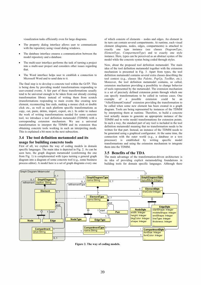
Figure 2. The way of coding models.
visualization tasks efficiently even for large diagrams.
• The property dialog interface allows user to communicate with the repository using visual dialog windows.
• The database interface ensures a communication between the model repository and a database.
• The multi-user interface performs the task of turning a project into a multi-user project and considers other issues regarding that.
• The Word interface helps user to establish a connection to Microsoft Word and to send data to it.
The final step is to develop a concrete tool within the GrTP. This is being done by providing model transformations responding to user-created events. A fair part of these transformations usually tend to be universal enough to be taken from our already existing transformation library instead of writing them from scratch (transformations responding to main events like creating new element, reconnecting line ends, making a mouse click or double click etc., as well as such platform specific transformations as copy, cut, paste, delete, import, export, etc.). In order to reduce the work of writing transformations needed for some concrete tool, we introduce a tool definition metamodel (TDMM) with a corresponding extension mechanism. We use a universal transformation to interpret the TDMM and its extension thus obtaining concrete tools working in such an interpreting mode. This is explained a bit more in the next subsection.
3.4 The tool definition metamodel and its usage for building concrete tools First of all, we explain the way of coding models in domain specific languages. The main idea is depicted in Fig. 2. As can be seen here, the graph diagram metamodel (conforming the one from Fig. 1) is complemented with types turning a general graph diagram into a diagram of some concrete tool (e.g., some business process editor). A model here is a set of graph diagrams every one
of which consists of elements – nodes and edges. An element in its turn can contain several compartments. At runtime, each visual element (diagrams, nodes, edges, compartments) is attached to exactly one type instance (see classes DiagramType, ElementType, CompartmentType) and to exactly one style instance. Here, types can be perceived as an abstract syntax of the model while the concrete syntax being coded through styles.
Now, about the proposed tool definition metamodel. The main idea of the tool definition metamodel together with the extension mechanism is presented in Fig. 3. Apart from types, the tool definition metamodel contains several extra classes describing the tool context (e.g., classes like Palette, PopUp, ToolBar, etc.). Moreover, the tool definition metamodel contains, so called, extension mechanism providing a possibility to change behavior of tools represented by the metamodel. The extension mechanism is a set of precisely defined extension points through which one can specify transformations to be called in various cases. One example of a possible extension could be an “AfterElementCreated” extension providing the transformation to be called when some new element has been created in a graph diagram. Tools are being represented by instances of the TDMM by interpreting them at runtime. Therefore, to build a concrete tool actually means to generate an appropriate instance of the TDMM and to write model transformations for extension points. In such a way, the standard part of any tool is included in the tool definition metamodel meaning that no transformation needs to be written for that part. Instead, an instance of the TDMM needs to be generated using a graphical configurator. At the same time, the connection with the outer world (e.g., a database or a text processor) is established by writing specific model transformations and using the extension mechanism to integrate them into the TDMM.
3.5 Benefits of the TDA The main advantage of the transformation-driven architecture is its idea of providing explicit metamodeling foundations in building tools for domain specific languages. Although there
Graph Diagram Metamodel
GraphDiagramcaption :String
GraphDiagramTypename:String
Element
Node Edge
Compartmentvalue:String
ElementTypename:String
NodeType EdgeType
CompartmentTypename:String
Pair
ElementStylelineColor:Integer...
NodeStylewidth: Integerheight: IntegerbkgColor: Integershape: Integer...
EdgeStylestartShape: IntegermiddleShape: IntegerendShape: IntegerlineType: Integerthickness: Integer...
GraphDiagramStylelayoutMode:Integer
CompartmentStylefontSize: IntegerfontColor: Integer...
*
*
start1
end1
* *
1..*
start1
end1
*1
*1
*1
*
*
0..1*
0..1*
0..1*
*
refinement0..1
*
refinementType0..1
0..11
0..11
0..11
3939

Figure 3. Basic principles of the tool definition metamodel.
already exist some metacase tools accepting the idea of DSL tool definition by a metamodel (e.g., Eclipse GMF [19] and Microsoft DSL Tools [20]), they generally offer only some configuration facilities allowing definition of a DSL tool in a user-friendly way while a direct access to metamodels is either limited or provided using some low level facilities. The pace-maker of the field is perhaps the Metacase company whose product MetaEdit+ [21] provides Graph, Object, Property, Port, Relationship and Role tools to ensure the easy configuration of concrete domain specific tools. Another well-known example is Pounamu/Marama [22, 23] which offers shape designer, metamodel designer, event handler designer and view designer to obtain a DSL tool. On the contrary, the TDA is completely transparent meaning a user can have a free read and write access to its metamodels and their instances. Of course, extra services like graphical configurator of a DSL tool can be offered as well, but the user is not forced to use it. It must be underlined that, if following the TDA, the definition of a concrete domain specific tool only involves developing model transformations and nothing else. The TDA follows the ideas of the MDA [24] stating that the common part of syntax and semantics can be formalized through a metamodel. The whole specific part at the same time can be put into model transformations.
The other notable advantage of the TDA is its ability to get in touch with the outer world. This is being done by adding new
engines to the TDA framework. Since there is no need to go deep in implementation details of other engines or other parts of the TDA, this is considered to be a comparatively easy task.
4. The development of PAD and SSIA using GrTP Besides the trivial part – generation of a tool definition metamodel’s instance forming the graphical core of the tool – we decided to develop three more engines we did not have at that moment. Those engines were the database engine, the multi-user engine and the Word engine. Since the TDA framework provides a possibility to plug in new interfaces (engines together with their respective metamodels) easily, the development and integration of the engines was done quite harmlessly. We must admit there were some difficulties to integrate the multi-user interface, however they were mostly of technical nature – the tool definition metamodel had to be changed a bit as well.
Next, according to the extension mechanism, some specific transformations needed to be written in order to put a life into the static tools – to make them dynamic. These transformations referred to generating, for instance, the correct items for combo boxes, to changing items in context menus dynamically, to assigning the correct styles to visual elements (although this can be partly specified in the static part as well) etc. These transformations had to be written and attached to appropriate
Tool Definition Metamodel: The Core (Simplified) Tool Definition Metamodel:Extension Mechanism (Simplified)
ElemStylename:String...
PaletteLine
Palette
PaletteBox
Toolname:String
ElemTypename:String
EdgeType
PairstartMultiplicityConstraint:MultiplicityendMultiplicityConstraint:Multiplicity
NodeTypemultiplicityConstraint:Multiplicity
CompartTypename:StringstartValue:StringisInElement:BooleanisInDialog:BooleanisEditable:Boolean
GraphDiagramStylelayoutMode:Integer...
PaletteElementname:Stringpicture:String
Before Element Deleted
After Element Modified
After Element Created
After Compart Created
After Compart Modified
AfterClick ComboBox
ListBox
CompartStylefontSize:IntegerfontColor:Integer
PopUpElementname:StringisVisible:Boolean
GraphDiagramTypename:String Keyboard
Toolbar
ToolbarElementname:Stringpicture:StringisVisible:Boolean
Keyname
PopUp
Transformationname: String
PredefinedToolbarElement AdvancedToolbarElement
*
defaultStyle 1
1
*
oElTypeoptionalStyle 1 *
dElTypedefaultStyle 1 0..1
start
* 1..*
{ordered} *
{ordered} *
end
*
1..*
start 1end 1
1..*
focusStart 0..1
dCompStyle
defaultStyle
1
0..1
oCompStyle
optionalStyle
1
*
*
*
first 1
{ordered} *
choiceItemsGenerator 0..1
{ordered}*
{ordered} *
{ordered} *
0..1
0..1
{ordered} *
{ordered} *
RClickElement 0..1
1
source
target
*
0..1
new
1
1..*
new
1
1
0..1
4040

Figure 4. Browsing for normative acts stored in the database from the tool’s dialog window.
Figure 5. A rich text component.
extension points thus forming the concrete tool.
The most challenging part of the development of tools was perhaps the ensuring interconnection between the tool and a relational database. Since the graphical tool was meant to be just one piece of the whole information system’s software, it was already clear before that this problem will have to be faced sooner or later. The issue has been classic in the world of workflows – some business process has been being modeled in a tool and passed to a relational database afterwards. The information system would then take care of applying the process to individual clients and storing the history of how far each client has gone through the process. On request, the tool should be able to visualize the history for some particular client as well.
The classic solution of the problem advises using the ORM method (Object-relational mapping, [25]) stating that a simple mapping between the model repository and the database must be made and a generation of metamodel instances and/or database records must be performed. However, this solution was not acceptable in our case because of its limitations in the process of generation of instances as a response to a query for the database – the types or return tables must be known before. At the same time, the SSIA project required the possibility of receiving answer to an arbitrary query.
Our solution included turning a part of the metamodel storing the business processes together with their respective element types and styles (see Fig. 2) into a database schema. That was a pretty straightforward job – if abstracting from the details, the database was made to store data in RDF format [26]. So, all the database engine had to do was generating the contents of the database from the model and vice versa. Next, a translator was made in an information system part of the system carrying out a connection between the RDF-type database and the actual database of the system. Thus, by introducing such an intermediate layer between the tool and the actual database, the database engine was to be written once and for all – it does not depend on the actual database schema.
Eventually, the tools obtained in GrTP satisfied all the needs customers had highlighted, including the ones mentioned in Section 2. The connection to the relational database provided by the database engine ensured fast information searching capabilities in database in combination with the tool. Thus, an easy browsing for information stored in the relational database (in
this case – normative acts) was possible from the tool interface (see Fig. 4). Next, an add-only DSL evolution comes at no extra cost if using the tool definition metamodel to develop tools in GrTP. Indeed, if the DSL demands some more element or compartment types to be added, we just add new instances to ElementType or CompartmentType classes in the model coding metamodel. Since it has nothing to do with already existing types of the language, existing models remain unmodified. This can be achieved because of the fact that we store the DSL definition in the same modeling level with the actual models – the connection between a model element and its definition is obtained without crossing levels. However, if changes in DSL are not of add-only type, some extra work needs to be done – elements and compartments of old types may need to be either deleted of relinked to some new types (see dashed associations in Fig. 2). In our framework, all this work can be done by model transformations. It must be mentioned that add-only changes are comparatively easy to implement in most metacase tools, although not in all. For example, it is still a quite tough problem in tools based on JGraLab repository [11].
Finally, a report generator was built using the Word engine. It introduces a simple graphical language allowing one to specify the information to be put in a Microsoft Word document. In the engine, several extra services were implemented as well. For example, a Word window was embedded in a property dialog windows generated by the property dialog engine and providing a possibility for a user to create rich text compartment values as was requested by the customer (see Fig. 5).
5. CONCLUSIONS In this paper, we described our approach how to develop new domain specific languages and tools for supporting them. A short description of the transformation-driven architecture and its framework was outlined as well. The architecture was illustrated in its application in the graphical tool building platform GrTP upon which two concrete domain specific languages were implemented.
It was mentioned that nowadays DSL is often to be only a part of some bigger information system and the tool supporting it thus must be able to communicate with the outer world. In fact, this approach is only one of the possible solutions for the problem of how to integrate the tool with other parts of an information system. The other possible way is to develop so called business process management suites in which all the necessary features are
4141

included. It involves also the issue of how to include fragments of existing information systems into a tool environment. It is usually done by turning components of the information system into a web service thus providing an appropriate network addressable application program interface for it.
Considering the issues mentioned above, our closest goal is to develop a platform for building domain specific suites. One of the possible domains for the approach could be suites incorporating process and document management integrated with sophisticated document generation procedures. Though large-scale expensive solutions such as EMC Documentum exist here, a very appropriate niche for small-scale, but logically sophisticated DSL-based solutions could be document management in various government institutions. The web service based approach will ensure very tight integration of the DSL execution environment with the rest of the suite including full access to databases.
6. REFERENCES [1] J. F. Chang. Business Process Management Systems.
Auerbach Publications, 2006, pp. 286. [2] UML, http://www.uml.org. [3] BPMN, http://www.bpmn.org. [4] BPEL, http://www.bpelsource.com. [5] BizAgi, http://www.bizagi.com. [6] Intalio, http://www.intalio.com. [7] ARIS platform, http://www.ids-
scheer.com/en/ARIS_ARIS_Software/3730.html. [8] J. Barzdins, A. Zarins, K. Cerans, A. Kalnins, E. Rencis, L.
Lace, R. Liepins, A. Sprogis. GrTP: Transformation Based Graphical Tool Building Platform. Proc. of Workshop on Model Driven Development of Advanced User Interfaces, MODELS 2007, Nashville, USA.
[9] J. Barzdins, S. Kozlovics, E. Rencis. The Transformation-Driven Architecture. Proceedings of DSM’08 Workshop of OOPSLA 2008, Nashville, USA, 2008, pp. 60–63.
[10] Eclipse Modeling Framework (EMF, Eclipse Modeling subproject), http://www.eclipse.org/emf.
[11] S. Kahle. JGraLab: Konzeption, Entwurf und Implementierung einer Java-Klassenbibliothek f¨ur TGraphen, Diplomarbeit, University of Koblenz-Landau, Institute for Software Technology, 2006.
[12] Sesame, http://www.openrdf.org, 2007. [13] J. Barzdins, A. Kalnins, E. Rencis, S. Rikacovs. Model
Transformation Languages and their Implementation by
Bootstrapping Method. Pillars of Computer Science, LNCS, vol. 4800, Springer-Verlag, 2008, pp. 130-145.
[14] A. Kalnins, J. Barzdins, E. Celms. Model Transformation Language MOLA, Proceedings of MDAFA 2004, LNCS, vol. 3599, Springer-Verlag, 2005, pp. 62-76.
[15] J. Barzdins, G. Barzdins, R. Balodis, K. Cerans, A. Kalnins, M. Opmanis, K. Podnieks. Towards Semantic Latvia. Communications of the 7th International Baltic Conference on Databases and Information Systems (Baltic DB&IS’2006), Vilnius, 2006, pp. 203-218.
[16] J. Barzdins, K. Cerans, S. Kozlovics, E. Rencis, A. Zarins. A Graph Diagram Engine for the Transformation-Driven Architecture. Proceedings of MDDAUI’09 Workshop of International Conference on Intelligent User Interfaces 2009, Sanibel Island, Florida, USA, 2009, pp. 29-32.
[17] P. Kikusts, P. Rucevskis. Layout Algorithms of Graph-Like Diagrams for GRADE Windows Graphic Editors. Proceedings of Graph Drawing ’95, LNCS, vol. 1027, Springer-Verlag, 1996, pp. 361–364.
[18] K. Freivalds, P. Kikusts. Optimum Layout Adjustment Supporting Ordering Constraints in Graph-Like Diagram Drawing. Proceedings of The Latvian Academy of Sciences, Section B, vol. 55, No. 1, 2001, pp. 43–51.
[19] A. Shatalin, A. Tikhomirov. Graphical Modeling Framework Architecture Overview. Eclipse Modeling Symposium, 2006.
[20] S. Cook, G. Jones, S. Kent, A. C. Wills. Domain-Specific Development with Visual Studio DSL Tools, Addison-Wesley, 2007.
[21] MetaEdit+, http://www.metacase.com. [22] N. Zhu1, J. Grundy, J. Hosking. Pounamu: a meta-tool for
multiview visual language environment construction. Proc. IEEE Symposium on Visual Languages and Human Centric Computing (VLHCC’04), 2004, pp. 254-256.
[23] J. Grundy, J. Hosking, N. Zhu1, N. Liu. Generating Domain-Specific Visual Language Editors from High-level Tool Specifications. 21st IEEE International Conference on Automated Software Engineering (ASE’06), 2006, pp. 25-36.
[24] MDA Guide Version 1.0.1. OMG, http://www.omg.org/docs/omg/03-06-01.pdf.
[25] C. Richardson. POJOs In Action. Manning Publications Co, 2006, pp. 560.
[26] Resource Definition Framework, http://www.w3.org/RDF.
4242

Use of a Domain Specific Modeling Language for RealizingVersatile Dashboards
Ulrich [email protected]
David [email protected]
Heiko [email protected]
Chair of Information Systems and Enterprise ModelingUniversity of Duisburg-Essen
Universitaetsstr. 9, 45141 Essen, Germany
ABSTRACTIn order to make performance indicators a useful instrumentto support managerial decision making, there is need to thor-oughly analyse the business context indicators are used inas well as their mutual dependencies. For this purpose, it isrecommended to design indicator systems that do not onlyinclude dedicated specifications of indicators, but that ac-count for relevant relationships. In this paper, a DSML isproposed that enables the convenient design of consistent in-dicator systems at type level, which supports various kindsof analyses, and can serve as conceptual foundation for cor-responding performance management systems, such as dash-board systems. Furthermore, indicator systems may also beused during run-time at the instance level to promote thedistinguished interpretation of particular indicator values.
KeywordsDomain-Specific Modeling Language, Enterprise Modeling,Performance Management, KPI
1. MOTIVATIONIn recent years, the increasing appreciation for performanceindicators has promoted the idea of systems that provideusers with performance related data. These systems, whichwe refer to as ’Performance Management Information Sys-tems’ (PMIS), are supposed to inform the individual user ata quick glance about the performance of entities such as anentire firm, specific business units, business processes, re-sources, and IT services. Inspired by technical metaphorssuch as ’cockpit’ or ’dashboard’, PMIS are more and moreconsidered as a general instrument to foster managerial ac-tion, especially with respect to supporting, measuring, andmonitoring decisions. The design of a PMIS implies the con-ception of indicators and systems of interrelated indicators(’indicator systems’). Indicator systems are usually definedby (top) management – with no regard of how they couldbe represented in an information system.
Current PMIS, such as dashboards, predominantly focus onthe visualization of indicators that are considered to be rel-evant for certain decision scenarios. For this purpose, dash-board systems provide generic visualization ’gadgets’, e.g.,speedometers, traffic lights, or bar charts, that are usuallyapplied to data originating from databases or files. However,to design PMIS that effectively support mangerial decisionmaking, focusing on visualization only is not sufficient [3].Instead, there is need to analyze what concepts are requiredto structure and effectively support a targeted decision.
Moreover, the design of indicator systems is not trivial. Al-ready the specification of an indicator does not only requirea profound understanding of the corresponding decision sce-nario and the relations to other indicators, but also recom-mends taking into account how an indicator affects manage-rial decision making [16, 19]; if managers regard an indicatoras an end in itself, it will result in opportunistic actions thatare likely not compliant with the objectives of a firm. Thisis even more important, because managers and other stake-holders are incited to predominantly align their behaviorwith specific (maybe mandatory) indicators and associatedtarget values only [12, 17, 20]. If PMIS do not adequatelyaddress these challenges, they are likely to fail their purpose.
In this paper, we present an approach for PMIS that incor-porates a domain-specific modeling language (DSML) for de-signing expressive and comprehensible indicator systems ascore element. The DSML, called ScoreML, aims at promot-ing transparency, especially with regard to counter dysfunc-tional effects of indicators such as opportunistic behaviour.Also, indicator systems created with the ScoreML serve asa conceptual foundation for developing corresponding soft-ware. In addition to this use at build-time, our approachmakes use of indicator systems at run-time as well, for ex-ample, as a front end to instance level performance data.
The approach is based on a comprehensive method for en-terprise modeling and consists of the following components:
• a domain-specific modeling method comprising a lan-guage for modeling indicator systems – the ScoreML– and a corresponding process model that guides its ap-plication;
• a modeling environment implementing a ScoreML ed-itor that is integrated with further editors for domain-specific modeling languages that are part of the enter-prise modeling method;
• a software architecture for PMIS, in which the modelingenvironment constitutes the core component and thatallows for integration with existing information systems.
Figure 1 illustrates the components of the PMIS. In this pa-per, we focus on the modeling language and its utilizationin the context of the envisioned systems architecture. Theother components are briefly discussed. The remainder isstructured as follows: We derive domain-specific require-ments for PMIS in Section 2. The prospects of our approachare illustrated in Section 3. The conceptual foundation, i.e.,
43 43
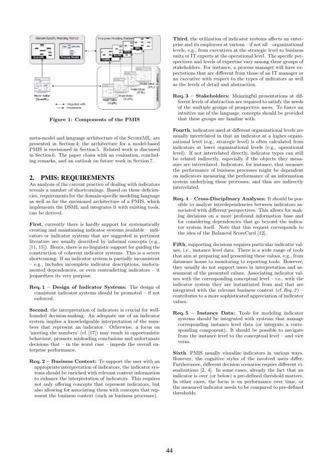
Figure 1: Components of the PMIS
meta-model and language architecture of the ScoreML, arepresented in Section 4; the architecture for a model-basedPMIS is envisioned in Section 5. Related work is discussedin Section 6. The paper closes with an evaluation, conclud-ing remarks, and an outlook on future work in Section 7.
2. PMIS: REQUIREMENTSAn analysis of the current practice of dealing with indicatorsreveals a number of shortcomings. Based on these deficien-cies, requirements for the domain-specific modeling languageas well as for the envisioned architecture of a PMIS, whichimplements the DSML and integrates it with existing tools,can be derived.
First, currently there is hardly support for systematicallycreating and maintaining indicator systems available – indi-cators or indicator systems that are suggested in pertinentliterature are usually described by informal concepts (e.g.,[11, 15]). Hence, there is no linguistic support for guiding theconstruction of coherent indicator systems. This is a severeshortcoming: If an indicator system is partially inconsistent– e.g., includes incomplete indicator descriptions, undocu-mented dependencies, or even contradicting indicators – itjeopardizes its very purpose.
Req. 1 – Design of Indicator Systems: The design ofconsistent indicator systems should be promoted – if notenforced.
Second, the interpretation of indicators is crucial for well-founded decision-making. An adequate use of an indicatorsystem implies a knowledgeable interpretation of the num-bers that represent an indicator. Otherwise, a focus on’meeting the numbers’ (cf. [17]) may result in opportunisticbehaviour, promote misleading conclusions and unfortunatedecisions that – in the worst case – impede the overall en-terprise performance.
Req. 2 – Business Context: To support the user with anappropriate interpretation of indicators, the indicator sys-tems should be enriched with relevant context informationto enhance the interpretation of indicators. This requiresnot only offering concepts that represent indicators, butalso allowing for associating them with concepts that rep-resent the business context (such as business processes).
Third, the utilization of indicator systems affects an enter-prise and its employees at various – if not all – organizationallevels, e.g., from executives at the strategic level to businessunits or IT experts at the operational level. The specific per-spectives and levels of expertise vary among these groups ofstakeholders. For instance, a process manager will have ex-pectations that are different from those of an IT manager oran executive with respect to the types of indicators as wellas the levels of detail and abstraction.
Req. 3 – Stakeholders: Meaningful presentations at dif-ferent levels of abstraction are required to satisfy the needsof the multiple groups of prospective users. To foster anintuitive use of the language, concepts should be providedthat these groups are familiar with.
Fourth, indicators used at different organizational levels areusually interrelated in that an indicator at a higher organi-zational level (e.g., strategic level) is often calculated fromindicators at lower organizational levels (e.g., operationallevel). If not interrelated directly, indicator types can stillbe related indirectly, especially if the objects they meaa-sure are interrelated. Indicators, for instance, that measurethe performance of business processes might be dependenton indicators measuring the performance of an informationsystem underlying these processes, and thus are indirectlyinterrelated.
Req. 4 – Cross-Disciplinary Analyses: It should be pos-sible to analyze interdependencies between indicators as-sociated with different perspectives. This allows for mak-ing decisions on a more profound information base andfor considering dependencies that go beyond the indica-tor system itself. Note that this request corresponds tothe idea of the Balanced ScoreCard [12].
Fifth, supporting decisions requires particular indicator val-ues, i.e., instance level data. There is a wide range of toolsthat aim at preparing and presenting these values, e.g., fromdataware house to monitoring to reporting tools. However,they usually do not support users in interpretation and as-sessment of the presented values. Associating indicator val-ues with the corresponding conceptual level – i.e., with theindicator system they are instantiated from and that areintegrated with the relevant business context (cf. Req. 2 ) –contributes to a more sophisticated appreciation of indicatorvalues.
Req. 5 – Instance Data: Tools for modeling indicatorsystems should be integrated with systems that managecorresponding instance level data (or integrate a corre-sponding component). It should be possible to navigatefrom the instance level to the conceptual level – and viceversa.
Sixth, PMIS usually visualize indicators in various ways.However, the cognitive styles of the involved users differ.Furthermore, different decision scenarios require different vi-sualizations [2, 4]. In some cases, already the fact that anindicator is over (or below) a pre-defined threshold matters.In other cases, the focus is on performance over time, orthe measured indicator needs to be compared to pre-definedthresholds.
44 44

Req. no. Description of Requirement
Req. 1 Promote design of consistent indicator systemsReq. 2 Offer concepts for business contextReq. 3 Provide abstractions for different stakeholdersReq. 4 Enable cross-disciplinary analysesReq. 5 Integrate type and instance levelReq. 6 Enable user-specific visualizations
Table 1: Summary of Requirements
Req. 6 – Visualization: Different stakeholders and differ-ent decision scenarios demand for versatile graphical rep-resentations of indicators. Therefore, it should be possibleto adapt graphical visualisations to the individual needs ofstakeholders without compromising the semantics of therepresented concepts.
Table 1 summarizes the requirements for a performance man-agement information system.
3. PROSPECTS OF THE APPROACHThe requirements pose the demand for an approach thatsupports the design and utilization of indicator systems in asystematic and structured manner. Conceptual models seemto be suitable, since they promise to reduce complexity byfocusing on those aspects that are essential – and abstractfrom other. In this regard, the ScoreML promises moreconsistent indicator systems and allows for various analy-ses that – without such a support – a user can hardly per-form. In the following, we illustrate the envisioned use ofthe DSML for designing and utilizing indicator systems atbuild-time as well as its potential for being leveraged as a’dashboard’ during run-time.
3.1 Focus on Build-TimeUsers design indicator systems with the ScoreML by choos-ing indicators they consider relevant and adquate to supportthe targeted decision. At first, these indicators will be de-scribed on a more abstract level that is usually hardly quan-tifiable, e.g. “competitiveness”. They can then refine thesehigh-level indicators until they get down to a set of indica-tors that allow for expressive quantifications. By associatingthem to the objects they refer to, i.e., the reference objectsthey measure, the indicators are enriched with additionalcontext information (cf. Req. 2 ). Once the indicator systemis designed, (yet undiscovered) interdependencies among in-dicators can be elicited.
Figure 2 exemplifies this procedure for an IT Manager. Itshows an indicator system model (top) and an excerpt ofintegrated IT resource/business process models (bottom).In the indicator system model, a few indicator types (at-tributes are omitted) for an IT-related indicator system aredisplayed. The indicator type efficiency of IT department iscalculated from IT costs and IT operations efficiency (calcu-lation rule is omitted, too). Some indicator types are asso-ciated to reference objects (an IT resource and two businessprocess types). Here, different perspectives on an enterpriseare accounted for: Two indicator types that are not directlyinterrelated (IT costs from an IT perspective and averagethroughput time from an operations perspective’s indicator
# IT costs [€]
IS &
Bus
ines
sIn
dica
tor S
yste
m
# Efficiency of IT department [%]
# Average throughput time [minutes]
< Business Process A >
# IT operations efficiency [%]
OperationsIT
IT
< Business Process B >uses
Business Process IT Resource: Desktop PC
Legend
Computed-from Relationship Measures Relationship
# IT costs [€] Indicator (Type)
uses
Figure 2: Short example including notation
system) are indirectly related; hence, an IT manager focus-ing on improving (e.g., reducing) IT costs only might, in theend, impede the performance of a related business processtype’s throughput time. If a timely execution of the processis more important than the IT costs of this resource, the ad-ditional business context information (cf. Ref. 2 ) and the ca-pability to navigate through the other models (e.g., businessprocess or IT resource models; cf.Req. 4 ) fosters decision-making (in this case of the IT manager). With regard to theScoreML, the IT Manager could establish a specific asso-ciation type between IT costs and average throughput time(e.g., ’influences’) that visualizes the potential cause and ef-fect relationship between these indicator types for furtherutilizations of the indicator system.1
3.2 Focus on Run-TimeBesides using models of indicator systems and the relatedmodels of the business context at build-time, they can alsobe used at run-time. A simplified example of an applicationscenario is illustrated in Figure 3.
A process owner, who is responsible for an online sales pro-cess, uses his personal dashboard to monitor the perfor-mance of the process. While the daily revenue correspondsto his expectations, the average throughput time (time be-tween ordering and notification of the customer that theorder has been approved) is exceeding its threshold. As aconsequence, the currently running (active) instances of thisprocess are affected, which are depicted in the lower sectionof Figure 3a.
To get a better understanding of the reasons for the dis-satisfactory performance, he investigates (’drill-down’) theindicators on which the critical indicator average throughputtime depends, i.e., is calculated from. An example model ofa business process Online Sales along with the required ITresources is displayed in Figure 3b.
The process payment activity is not functioning properly be-cause the required part of the ERP-system is not available.The process owner escalates the problem to the IT staff, e.g.,
1Further, more extensive examples of indicator system mod-els by means of ScoreML can be found in [7] and athttp://openmodels.org/node/190.
45 45

050100150200250300350400450
09:55
10:00
10:05
10:10
10:15
10:20
10:25
10:30
10:35
10:40
10:45
10:50
10:55
10 8 9 5 10 8
5 3 2 10 5 32
1 05 10
2
0
10
20
30
CW 28
CW 29
CW 30
CW 31
CW 32
CW 33
Database Server
Busi
ness
Indi
cato
r Sy
stem
# Average throughput time [minutes]
Operations
depends on
Inst
ance
s
# Daily Renue [$]
Finance
#147‐090810‐10:53:58#145‐090810‐10:49:23
#148‐090810‐10:55:01#146‐090810‐10:52:11
Online Sales
319800302088
246000
186960221400
3.8 4.8 5.8 6.8 7.8
6030
Busi
ness
process ordercheck availability process payment
product in stock
shopping completed
order processed
ERP System
...
IS
# Average throughput time [minutes]
Operations
Indi
cato
r Sy
stem
0
10
20
30
40
50
60
70
80
09:55
10:00
10:05
10:10
10:15
10:20
10:25
10:30
10:35
10:40
10:45
10:50
10:55
ISBu
sine
ssIn
dica
tor
Syst
em
# Response Time [ms]
Operations
# Incidents [#/week]
Operations
Online Sales CRM
Credit Card Checking(external)
Application Server
Backup
Network
Service
Firewall
ERP System
depends on
(a
(b
(c
0102030405060
0
10
20
30
40
50
Figure 3: Dashboard for an Online Sales Process
through a ticket that refers to the particular business processand the malfunctioning IS. A member of the IT staff receivesa notification about the incident. Hence, he uses his dash-board to assess the business impact (e.g., how many businessprocesses are impacted? What is the loss of revenues to beexpected in case of an outage?) of the incident. An ex-cerpt of a model of the ERP system is displayed in Figure 3calong with corresponding indicators. The service credit cardchecking is offered by an external partner and securely ac-cessed through a firewall. Obviously, the connection is notstable, i.e., has a high response time. Furthermore, the fire-wall was subject of several severe problems (’incidents’) inthe past weeks. Based on the information available, the usercan decide what to do next, e.g., contact the vendor of thefirewall and demand for a satisfactory solution.
4. MODEL-BASED PMISThe ScoreML is based on a formal syntax and precisesemantics, which provides two advantages over non-formalor general purpose approaches: First, it effectively supportsand constrains users to build consistent and syntacticallycorrect models (cf. Req. 1 ) as well as it facilitates conve-nient, intuitive, and secure modeling. Second, a DSMLenables various kinds of analyses and transformations in-cluding code generation for corresponding software (cf.[13]).Furthermore, the ScoreML comprises a graphical notationwith specialized, interchangable icons, which fosters com-munication between stakeholders with different professionalbackgrounds (cf.Req. 3 ).
4.1 Language ArchitectureThe approach we chose to develop the DSML is to enhancean existing method for enterprise modeling (EM) – the multi-perspective enterprise modeling (MEMO)-method [5] – byconcepts and further components for designing and utilis-ing indicator systems. MEMO consists of an extensible setof domain-specific modeling languages meant to model dif-ferent aspects of an enterprise, such as corporate stratetgy(with the Strategy Modeling Language, SML; [8]), businessprocesses (Organization Modeling Language, OrgML; [5]),resources (Resource Modeling Language, ResML; [10]), orIT resources (IT Modeling Language, ITML; [14]). MEMOis multi-perspective since it provides different views on var-ious aspects of an enterprise. The MEMO languages areintegrated in two ways (cf. [6]): First, they are integrated bya common meta meta model (M3), so that the DSMLs arebased on the same language specification (meta language).Second, they share common concepts at the meta level (M2),which enables the integration of different perspectives (andmodels) addressed by each DSML (e.g., a meta concept’business process’ in OrgML and ITML).
Figure 4 illustrates the language architecture of MEMO andthe interrelations between the DSMLs and the correspond-ing models at type level (M1). Integrating the proposedDSML with the MEMO framework allows to benefit from avariety of existing modeling languages. Thereby, it is possi-ble to associate indicator systems with models of the busi-ness context (cf.Req. 2 ) and representations different groupsof stakeholders are familiar with (cf. Req. 3 ). Furthermore,the integration of the models provides a foundation to en-able cross-disciplinary analyses that span various perspec-tives (cf. Req. 4 ).
46 46

Figure 4: MEMO Language Architecture
4.2 Language Specification: ScoreMLThe DSML is specified in a meta model using the MetaModeling Language MML (cf. [6]). Figure 5 shows an ex-cerpt of the ScoreML’s meta model and depicts its mainconcepts. The specification of the language faced a numberof challenges. Three important issues are addressed below.
First, ScoreML has to provide the users with a preciseconception of indicators. From a modeling perspective, anindicator can be an attribute of an object, e.g., ’IT costs’ ofa piece of hardware; an aggregation of attributes of a collec-tion of objects, e.g., the sum of ’IT costs’ of all IT resources;or it can represent a snapshot of certain states over time,e.g., ’Average monthly IT costs’. In order to provide theuser with convenient modeling concepts, we decided to intro-duce a specific abstraction rather than regarding indicatorsas attributes of objects or object collections. Such a concep-tion includes core attributes and a differentiated conceptionof relationships between indicator types. This is realized bythe meta type Indicator that comprises predefined attributes(e.g., name and description, purpose, potential bias) and aset of self-reflexive association types (e.g., computed from orsimilar to). We further introduced the association type Cus-tomizedRelationship that enables users to qualify additionalrelations between indicators – for instance, an indicator canhave an effect on another indicator (cf. Section 3.1). Addi-tional customized attributes and non-’1..1’-associations canbe realized by the meta types ’IndicAttributes’ and ’Indi-cLink’.2
The second decision pertains to the flexibility and adapt-ability of indicators. The ScoreML has to allow users foradapting indicators to their individual needs and, further-more, enrich indicators with additional semantics concern-ing the context they are used in. The former is addressed bydistinguishing the concept indicator into the meta types In-dicator and SpecificIndicator : While instances of Indicatorrepresent generic information about an indicator type, Speci-ficIndicator allows users to assign this indicator type to spe-cific reference object types, e.g., an indicator type ’averagethroughput time’ assigned to ’business process type A’ andto ’business process type B’, including different values in theattributes benchmark, (avg.) value etc. In this context, themeta type Threshold allows for defining user-specific thresh-
2Note, the meta model at hand is a simplification due tothe given restrictions of this paper. The full version can befound at http://openmodels.org/node/190.
olds and corresponding notifications for a SpecificIndicator.This enables users to develop their individual ’performancedashboard’ that includes indicators, thresholds, correspond-ing notifications and visualizations, and that fits to theirpersonal cognitive style (cf. Req. 6 ). The latter – the needfor additional semantics – is tackled by the meta types Ref-erenceObject, which is a surrogate for meta types like Busi-nessProcess, Resource, Product etc., and DecisionScenario,which enables the mapping of indicator types to scenariotypes (e.g., ’assessment of IT resources’). Note, the surro-gate serves to illustrate the integration of ScoreML withthe other MEMO languages: An indicator can be assignedto each (reasonable) meta type in one of the other DSMLs,which is the foundation for performing cross-disciplinaryanalyses. The re-use of concepts from other languages isdenoted in the meta model with a rectangle at the con-cepts headers, including information about the origin (seethe color legend in Figure 5).
Third, it is required to differentiate between types and in-stances of indicators: An indicator system contains typesof indicators, while indicators that actually measure perfor-mance are instances. Especially with regard to Req. 5, itwould not be satisfactory to neglect such instance level fea-tures. For example, a specific indicator type has a ’value’applying to a business process type (e.g., an average overall instances of this business process type); instances of thisspecific indicator type have a particularValue, describing theconcrete value of a (projection of) process instance(s), e.g.,at a certain time. To address this challenge, we make useof the concept ’intrinsic feature’ [6]. An intrinsic feature– marked in the meta model with an ’i’ printed white onblack – is a type, an attribute or an association defined onmeta level, but that reflects a characteristic we associateonly to the instance level. Hence, although defined in themeta model this feature is not instantiated at type level butat instance level.
5. CORRESPONDING ARCHITECTUREThe outlined vision – designing and utilizing indicators inan versatile dashboard based on a DSML – requires an ar-chitecture for the PMIS that conforms to the requirementsidentified in Section 2.
First, there is need for a modeling environment that sup-ports the user in designing and maintaining consistent indi-cator systems and, thus, implements the ScoreML. Figure 6illustrates the modeling environment in the context of thePMIS architecture. It comprises a modeling editor for theScoreML as well as – with regard to the integration withan enterprise modeling method – modeling editors for theother modeling languages.
Although the editors are separate, the underlying meta mod-els are integrated (cf. Section 4). Thereby, the modeling en-vironment maintains just a single model (’common modelrepository’), and the editors act on a defined set of concepts– i.e., parts – of this model. Hence, the ’surrogates’ for ref-erence objects in Fig. 5 are replaced by concrete meta typesof other (MEMO) languages, like meta types for businessprocesses or resources as indicated in the short example inFigure 2. This facilitates, e.g., cross-model integrity checks,since reference objects in the indicator system model refer-
47 47
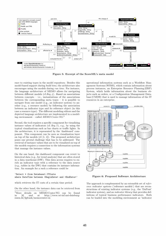
SpecificIndicatorbenchmark : Decimalvalue : Decimalavailability : Stringdatasource : String particularValue : Decimal measuredAt : Date
BusinessProcess
IndicatorCategoryname : Stringdescription : String
Indicatorname : Stringdescription : Stringpurpose : Stringexamples : Stringpresumptions : StringpreferredVisualisation : String
ReferenceObject
Resource Product
OrganizationalRolename : Stringresponsibility : String
ii
computed from
1,1
of kind
similar to
used
in
surrogate for
in charge ofpart of
part
of
valid for
measures0,1
0,1
1,1
context SpecificIndicator inv:self.decisionScenarios->forAll (d | self.indicator.decisionScenarios->includes: d)
C1used in
CustomizedRelationshipname : StringrelationSpecification : Stringpresumptions : String 1,1
affecting via
DecisionScenarioname : StringtriggeredBy : Stringchallenge : StringsuccessFactors : String
affected by
1,1
measuresi
notifies
OrgML
ResML and ITML
ProdML
Color legend for concepts reusedfrom other MEMO languages:
iFurther symbols:
’Intrinsic Feature’
0,*
0,10,*
1,10,*
0,*
0,*
0,*0,*
0,*
0,*
0,*
0,*
0,*
0,*
0,10,*
0,1
0,*
0,*
0,*
1,1
ThresholdthresholdValue : Stringaction : Stringseverity : String
i
Figure 5: Excerpt of the ScoreML’s meta model
ence to existing types in the model repository. Besides thismodel-based support during build time, the architecture alsoencourages using the models during run time. For instance,the language architecture of MEMO allows for navigatingbetween different models (cf.Req. 4 ). Based on associationsbetween concepts – i.e., instantiations of the associationsbetween the corresponding meta types – it is possible tonavigate from one model (e.g., an indicator system) to an-other (e.g., a resource model) by following the associationbetween an indicator type and its reference object (in thiscase a resource type). The different modeling editors and thedepicted language architecture are implemented in a model-ing environment – called MEMO Center NG.3
Second, the tool requires a specific component for visualizinginstance values of indicators (cf. Req. 5 ), e.g., by using thetypical visualizations such as bar charts or traffic lights. Inthe architecture, it is represented by the ’dashboard’ com-ponent. This component can be seen as visualization layeron top of the models (cf. [1, 4]). The proposed architectureposes one pivotal challenge that has to be addressed: Theretrieval of instance values that are to be visualized on top ofthe models requires a connection to the information systemsthat manage the instance values.
On the one hand, the dashboard component can revert tohistorical data (e.g., for trend analysis) that are often storedin a data warehouse (DW). This data access requires to en-rich an indicator type with a reference to the data source(e.g., tables in the DW) that contains its instance informa-tion. An example for a such a reference could be
’Select * from Database1.ITCosts
where DateTime between <BeginDate> and <EndDate>’
which retrieves the IT costs of a certain time period.
On the other hand, the instance data can be retrieved from
3More details on MEMO Center NG can be foundin [6] and at http://www.wi-inf.uni-duisburg-essen.de/fgfrank/memocenter-en
operational information systems such as a Workflow Man-agement Systems (WfMS), which contain information aboutprocess instances, an Enterprise Resource Planning (ERP)System, which holds information about the business ob-jects such as orders, or a Configuration Management Data-base (CMDB) that is used to manage information of the ITresources in an enterprise.
Figure 6: Proposed Software Architecture
The approach is complemented by an extensible set of refer-ence indicator systems (’reference models’) that are recon-structions of existing indicator systems (e.g., the ’DuPont’indicator system), and an indicator library that provides def-initions of typical business performance indicators. Bothcan be loaded into the modeling environment as ’indicator
48 48

systems building blocks’, which serve as a basis for an en-terprise specific adaption. More details on the purpose ofreference indicator systems and the indicator library can befound in [7].
6. RELATED WORKThere are various information systems to support perfor-mance management. However, these tools often focus onthe presentation of quantitative data, and they do not pro-vide the user with additional information about indicators ortheir semantics (like their business context or effect-relationsto other indicators; cf. Req. 1 & 2 ). In this regard, datawarehouses store data that is extracted, transformed, andloaded from operational information systems to enable var-ious analyses with respect to certain dimensions (like time,region, product) [9]. Thus, data warehouses provide a valu-able data source for indicator instances (cf. Fig. 6). Unfor-tunately, data in data warehouses remain on a low levelof semantics. Few approaches exist that try to augmentdata warehouses with additional context information. Forinstance, extensions of the EERM [21] or DSMLs [22] existthat allow for modeling dimensions for multi-dimensionalstructure of data and the navigation between these dimen-sions, e.g., roll-up or drill-down; hence, they complementour approach with respect to creating and maintaining thedata warehouse underlying the PMIS architecture.
There are some commercial tools available (e.g., ARIS4,ADOscore5) that also offer concepts for specifying indica-tors and – to some extent – allow for assigning them to con-cepts that represent the business context. However, theirlanguage specification is usually not available, and thus theconcepts underlying the tool (i.e., the meta models) have tobe reconstructed. As far as we can assess those tools, onlyADOscore contains a more elaborate conception for indica-tors with respect to Req. 1. Unfortunately, this software isnot (fully) integrated with the other ADO-modeling tools(esp., ADONIS), so it still lacks the integration of indicatorsystems with the business context.
When we developed the indicator modeling method in thecontext of MEMO, we built upon approaches that focus onindicator modeling (like [18, 23]) and extended those by (1)additional concepts for indicators (e.g., relations) and (2)concepts for the business context (cf. [7] for a more extensivedescription of these approaches).
7. EVALUATION & FUTURE WORKIn this paper, we outlined the domain-specific modeling lan-guage ScoreML for designing and utilizing indicator sys-tems. The language is part of a PMIS that enables usingthe DSML not only at build-time, but also as versatile frontend to instance-level performance data at run-time.
The PMIS consists of several components: a method forindicator modeling, which comprises the DSML and a cor-responding process model, a modeling environment that im-plements the modeling languages, and a software architec-ture to enable the design and realization of versatile dash-boards. In this paper, we focused on the modeling language
4http://www.ids-scheer.com5http://www.boc-group.com
and its utilization in the context of the envisioned systemsarchitecture (the other parts are introduced in [7]). The de-sign of the language and the corresponding architecture forPMIS were guided by six requirements:
The concepts of the ScoreML have been reconstructed froman existing technical language. Hence, the ScoreML pro-vides its users with an elaborate linguistic structure thatguides them with designing transparent and consistent indi-cator systems (Req. 1 ). By embedding the ScoreML into amethod for enterprise modeling that also supports modellingof, e.g., processes, resources, and goals, the indicator modelscan be enriched with information about the relevant businesscontext (Req. 2 ). Due to the integration of the ScoreMLwith other modelling languages (here: the family of MEMOlanguages), different perspectives on indicator systems aresupported, e.g., from IT management and business manage-ment. This fosters collaboration and communication amongthe different stakeholders involved (Req. 3 ), as well as it fa-cilitates the analysis of interdependencies between indicatorsassociated with different perspectives (Req. 4 ). We furtherintroduced means in language specification and architectureto integrate the indicator system models with tools thatmanage corresponding instance level data (Req. 5 ) and thatenable the design and utilization of individual performancedashboards (Req. 6 ). Compared to the prevalent practiceof creating indicator systems, the ScoreML is promisingclear advantages. However, further studies are required toanalyze factors such as acceptance and further conditions ofsuccessful use in practice.
In our future work we focus on further refining the language.This includes research on the technical integration betweenthe modeling environment and the operational informationsystems. Also, we will enhance an existing library of ref-erence indicator systems. We will also continue our workon model-driven development of versatile early-warning sys-tems.
AcknowledgmentsThis research was partially funded by CA Inc. We thank ourproject partners for their support and valuable comments onpreliminary versions of our research results.
8. REFERENCES[1] S. Buckl, A. M. Ernst, J. Lankes, F. Matthes, C. M.
Schweda, and A. Wittenburg. GeneratingVisualizations of Enterprise Architectures using ModelTransformation. Enterprise Modelling and InformationSystems Architectures – An International Journal,2(2):3–13, 2007.
[2] W. W. Eckerson. Performance Dashboards:Measuring, Monitoring, and Managing Your Business.Wiley & Sons, Hoboken, NJ, 10 2005.
[3] S. Few. Dashboard Design: Taking a Metaphor TooFar. DMReview. com. March, 2005.
[4] S. Few. Information Dashboard Design: The EffectiveVisual Communication of Data. O’Reilly, Beijing,2006.
[5] U. Frank. Multi-Perspective Enterprise Modeling(MEMO): Conceptual Framework and ModelingLanguages. In Proc. of the 35th Hawaii International
49 49

Conference on System Sciences (HICSS-35).Honolulu, 2002.
[6] U. Frank. The MEMO Meta Modelling Language(MML) and Language Architecture. ICB-ResearchReport 24, Institut fur Informatik undWirtschaftsinformatik (ICB), University ofDuisburg-Essen, 2008.
[7] U. Frank, D. Heise, H. Kattenstroth, and H. Schauer.Designing and Utilising Business Indicator Systemswithin Enterprise Models – Outline of a Method. InP. Loos, M. Nuttgens, K. Turowski, and D. Werth,editors, Modellierung betrieblicherInformationssysteme (MobIS 2008), volume 141 ofLecture Notes in Informatics, pages 89–106, 2008.
[8] U. Frank and C. Lange. E-MEMO: a method tosupport the development of customized electroniccommerce systems. Inf. Syst. E-BusinessManagement, 5(2):93–116, 2007.
[9] W. Inmon. Building the data warehouse. John Wiley& Sons, Inc. New York, NY, USA, 1996.
[10] J. Jung. Entwurf einer Sprache fur die Modellierungvon Ressourcen im Kontext derGeschaftsprozessmodellierung. Logos, Berlin, 2007.
[11] R. Kaplan and D. Norton. Strategy Maps. HarvardBusiness School Press, 2003.
[12] R. Kaplan and D. P. Norton. The Balanced Scorecard:Measures That Drive Performance. Harvard BusinessReview, 1992.
[13] S. Kelly and J.-P. Tolvanen. Domain-SpecificModeling: Enabling Full Code Generation. Wiley, NewYork, 2008.
[14] L. Kirchner. Eine Methode zur Unterstutzung desIT–Managements im Rahmen derUnternehmensmodellierung. Logos, Berlin, 2008.
[15] R. L. Lynch and K. F. Cross. Measure Up!: Yardsticksfor Continuous Improvement. Wiley, Blackwell, 1991.
[16] A. D. Neely, M. Gregory, and K. Platts. Performancemeasurement system design. a literature review andresearch agenda. INT J OPER PROD MAN,15(4):80–126, 1995.
[17] B. Perrin. Effective Use and Misuse of PerformanceMeasurement. American Journal of Evaluation,19(3):367–379, 1998.
[18] A. Pourshahid, P. Chen, D. Amyot, M. Weiss, andA. Forster. Business Process Monitoring andAlignment: An Approach Based on the UserRequirements Notation and Business IntelligenceTools. 10th Workshop of Requirement Engineering.,pages 80–91, 2007.
[19] V. F. Ridgway. Dysfunctional Consequences ofPerformance Measurements. Administrative ScienceQuarterly, 1(2):240–247, 1956.
[20] J. M. Rosanas and M. Velilla. The Ethics ofManagement Control Systems: Developing Technicaland Moral Values. Journal of Business Ethics,57(1):83–96, 2005.
[21] C. Sapia, M. Blaschka, G. Hofling, and B. Dinter.Extending the E/R Model for the MultidimensionalParadigm. In ER ’98: Proceedings of the Workshopson Data Warehousing and Data Mining, pages105–116, London, UK, 1999. Springer-Verlag.
[22] Y. Teiken and S. Floering. A common meta-model fordata analysis based on dsm. In J. Gray, J. Sprinkle,J.-P. Tolvanen, and M. Rossi, editors, The 8thOOPSLA workshop on domainspecific modeling(DSM), 2008.
[23] B. Wetzstein, Z. Ma, and F. Leymann. Towardsmeasuring key performance indicators of semanticbusiness processes. In W. Abramowicz and D. Fense,editors, BIS, volume 7 of LNBIP, pages 227–238,Innsbruck, Austria, 2008. Springer.
50 50

DSML-Aided Development for Mobile P2P Systems Tihamér Levendovszky, Tamás Mészáros, Péter Ekler, Márk Asztalos
Department of Automation and Applied Informatics Budapest University of Technology and Economics
H-1111 Budapest Goldmann György tér 3. IV. em.
Tel.:+36-1-463-2870
{tihamer, mesztam, ekler.peter, asztalos}@aut.bme.hu
ABSTRACT The proliferation of Mobile P2P systems made a next generation mobile BitTorrent client an appropriate target to compare two different development approaches: the traditional manual coding and domain-specific modeling languages (DSMLs) accompanied by generators. We present two DSMLs for mobile communication modeling, and one for user interface development. We compare the approaches by development time and maintenance, using our modeling and transformation tool Visual Modeling and Transformation System (VMTS).
Categories and Subject Descriptors D.2.2 [Software Enginering]: Design Tools and Techniques – state diagrams, user interfaces. D.2.13 Reusable Software – domain engineering.
General Terms Design, Languages
Keywords Domain Engineering, Methodologies, Graphical environments, Interactive environments, Specialized application languages
1. INTRODUCTION Mobile Peer-to-Peer technology is a natural demand fueled by the appearance of Smart Phones on the market. The Applied Mobile Research Group at our department did pioneering work in this area. Symella, the first Gnutella client for Symbian OS, has been downloaded by more than 400,000 users since its first public release in the summer of 2005. SymTorrrent is the first BitTorrent client for mobile phones. The first free public version was available in 2006 October, as of writing the software has been downloaded by about 300,000 clients. In order to involve mainstream phones into P2P networks, Péter Ekler has developed a BitTorrent client named MobTorrent for Java ME platform [1]. The original goal was to examine whether mainstream phones are able to run such complex applications. The experiment has met the expectations, and MobTorrent became a suitable for communicate with the BitTorrent network. The experience stemming from the products made MobTorrent an apt environment where we could compare the manual coding and the Domain-Specific Modeling Language (DSML)-aided development. Having developed the manually coded version, we started with creating domain-specific languages which can be used to describe P2P systems for mobile applications. We identified two main
functionality groups where the DSMLs are useful: processing the protocol messages and designing the user interface. As a DSML platform, we chose the metamodeling and model transformation tool Visual Modeling and Transformation System (VMTS) [2]. In VMTS, we could create the DSMLs, and we could write the model processors that translate the models into Java ME code. We tried to address the following issues:
• How can Mobile P2P application benefit from DSMLs? • Does the DSML technology pays off at all in mobile P2P
development in time? • Do the domain-specific models require less maintenance
effort? • Could the DSML approach accelerate the development of
the future versions?
We start with answering the first question by giving an insight of the used DSLs, moreover, we show how we got the facts that underpin the answers.
2. Domain-Specific Languages for Mobile P2P Systems In VMTS, we developed an integrated environment to visually model different aspects of JAVA ME mobile applications, and code generators to turn the models into executable JAVA code. The Java Resource Editor DSL is appropriate for the rapid development of the static components of mobile applications, while the JAVA Network Protocol Designer can be used to model the static components and the dynamic behavior of simple, message-based network protocols.
2.1 Java ME Network Communication Support The basics of BitTorrent technology [3] are as follows. In order to download content via BitTorrent, firstly we need a very small torrent file. This file contains some meta-data describing the content and the address of at least one central peer called Tracker, which manages the traffic. After we have the torrent file, the BitTorrent client connects to the Tracker, which sends a set of addresses of other peers back to the client. Next the client connects to these addresses and concurrently downloads the content from them via a BitTorrent-specific peer-wire protocol [2]. In BitTorrent, we can download the content simultaneously from different peers.
5151
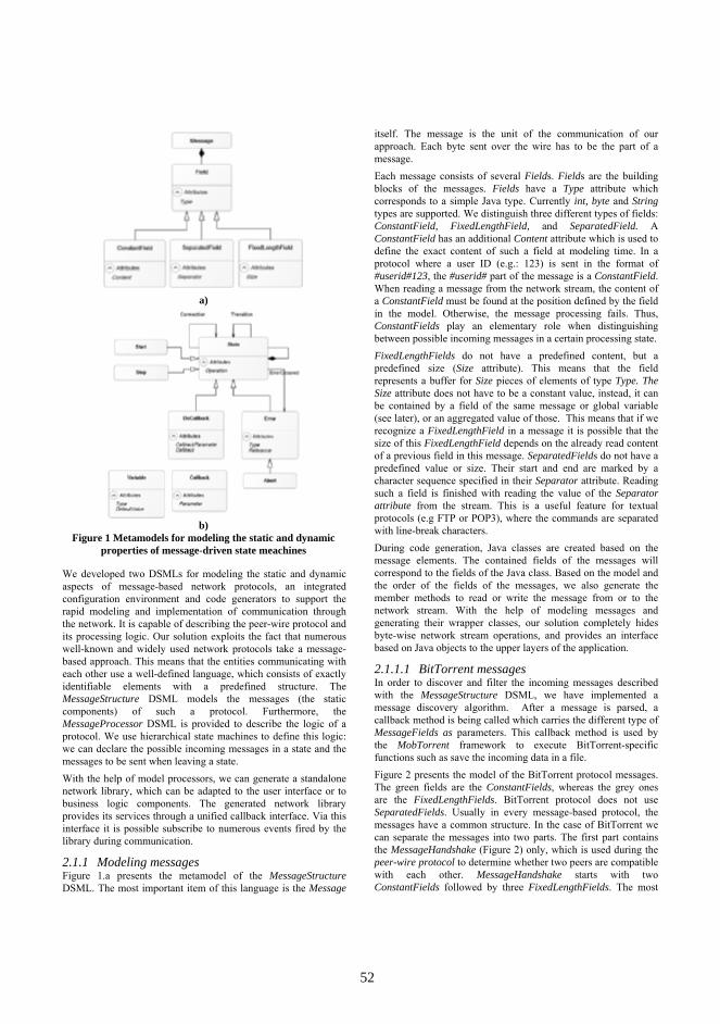
We developed two DSMLs for modeling the static and dynamic aspects of message-based network protocols, an integrated configuration environment and code generators to support the rapid modeling and implementation of communication through the network. It is capable of describing the peer-wire protocol and its processing logic. Our solution exploits the fact that numerous well-known and widely used network protocols take a message-based approach. This means that the entities communicating with each other use a well-defined language, which consists of exactly identifiable elements with a predefined structure. The MessageStructure DSML models the messages (the static components) of such a protocol. Furthermore, the MessageProcessor DSML is provided to describe the logic of a protocol. We use hierarchical state machines to define this logic: we can declare the possible incoming messages in a state and the messages to be sent when leaving a state. With the help of model processors, we can generate a standalone network library, which can be adapted to the user interface or to business logic components. The generated network library provides its services through a unified callback interface. Via this interface it is possible subscribe to numerous events fired by the library during communication.
2.1.1 Modeling messages Figure 1.a presents the metamodel of the MessageStructure DSML. The most important item of this language is the Message
itself. The message is the unit of the communication of our approach. Each byte sent over the wire has to be the part of a message. Each message consists of several Fields. Fields are the building blocks of the messages. Fields have a Type attribute which corresponds to a simple Java type. Currently int, byte and String types are supported. We distinguish three different types of fields: ConstantField, FixedLengthField, and SeparatedField. A ConstantField has an additional Content attribute which is used to define the exact content of such a field at modeling time. In a protocol where a user ID (e.g.: 123) is sent in the format of #userid#123, the #userid# part of the message is a ConstantField. When reading a message from the network stream, the content of a ConstantField must be found at the position defined by the field in the model. Otherwise, the message processing fails. Thus, ConstantFields play an elementary role when distinguishing between possible incoming messages in a certain processing state. FixedLengthFields do not have a predefined content, but a predefined size (Size attribute). This means that the field represents a buffer for Size pieces of elements of type Type. The Size attribute does not have to be a constant value, instead, it can be contained by a field of the same message or global variable (see later), or an aggregated value of those. This means that if we recognize a FixedLengthField in a message it is possible that the size of this FixedLengthField depends on the already read content of a previous field in this message. SeparatedFields do not have a predefined value or size. Their start and end are marked by a character sequence specified in their Separator attribute. Reading such a field is finished with reading the value of the Separator attribute from the stream. This is a useful feature for textual protocols (e.g FTP or POP3), where the commands are separated with line-break characters. During code generation, Java classes are created based on the message elements. The contained fields of the messages will correspond to the fields of the Java class. Based on the model and the order of the fields of the messages, we also generate the member methods to read or write the message from or to the network stream. With the help of modeling messages and generating their wrapper classes, our solution completely hides byte-wise network stream operations, and provides an interface based on Java objects to the upper layers of the application.
2.1.1.1 BitTorrent messages In order to discover and filter the incoming messages described with the MessageStructure DSML, we have implemented a message discovery algorithm. After a message is parsed, a callback method is being called which carries the different type of MessageFields as parameters. This callback method is used by the MobTorrent framework to execute BitTorrent-specific functions such as save the incoming data in a file. Figure 2 presents the model of the BitTorrent protocol messages. The green fields are the ConstantFields, whereas the grey ones are the FixedLengthFields. BitTorrent protocol does not use SeparatedFields. Usually in every message-based protocol, the messages have a common structure. In the case of BitTorrent we can separate the messages into two parts. The first part contains the MessageHandshake (Figure 2) only, which is used during the peer-wire protocol to determine whether two peers are compatible with each other. MessageHandshake starts with two ConstantFields followed by three FixedLengthFields. The most
a)
b)
Figure 1 Metamodels for modeling the static and dynamic properties of message-driven state meachines
5252

important field in the MessageHandshake is the torrentInfoHash, which is basically the SHA-1 value of the torrent file. This value is used to determine whether the peers are interested in the same content represented by the torrent file. According to the protocol when peers are exchanging the handshake message, this is the only message which can be accepted, thus, it is easy to discover. After a successful handshake every other message can be sent or received, there are no limitations. However we can see that the structure of these messages is the same. All of them start with a messageLength field which defines the length of the message in four bytes. Figure 2 shows that the messageLength field is green in all the messages, except for MessagePiece and MessageBitfield. The length of these two messages depends on the amount of data they carry. Following the messageLength, each message contains a messageID field which makes it easy to filter the messages. Only the MessageKeepAlive does not have this messageID field, because it contains only a messageLength constant field. In the BitTorrent protocol, after we have parsed the messageID field, we can easily determine which message has arrived, and we can pass the content of the incoming message as the parameters of the callback functions.
2.1.2 Modeling dynamic behavior The core concept of our approach is that that communication layer performs status changes as a consequence of receiving specific messages from the network stream. In addition, we may also instantiate and send network messages during a status change. In our approach, the communication layer can run standalone, and it informs the connecting components of the application through a callback interface about the important events of the communication. The business logic can influence the behavior of the communication layer through the parameters of the layer and by sending messages directly through the network stream. The behavior of the network layer can be modeled with the help of a message-driven state machine. Figure 1.b presents the metamodel of the MessageProcessor DSL. The most elementary item of this state machine is the State. There are two special types of states: the Start and the Stop states. The Start state indicates the entry point of the state machine, while the Stop state indicates the exit point. As states can be nested (see the containment edge-loop in the metamodel), the start and end states may also be used as the entry/exit point of a sub-state machine.
States can be connected with the help of Transition edges. A Transition edge may trigger the reception of a specific message from the stream: the type of the expected message is defined by the MessageTypeIn attribute of the edge, which references an already modeled message. If several outgoing transition edges are connected to the same state, then the transition whose triggered message first arrives will be chosen. If a transition is chosen, the state pointed by its right end will be the next active state. When activating a state, the instruction described in its Operation attribute is executed. An important issue in every message-based protocol is the phase where we have to decide which message has exactly arrived. We have implemented an advanced message handling algorithm especially for the presented MessageStructure DSL: in each state of the protocol we have a set of messages which can arrive in the state. Each message knows how many bytes it can consume to process its current (still not read) field. If the size of the current field cannot be determined (in case of a SeparatedField or a FixedLengthField with variable size) then this message can process only one byte. The key point is that we can increase the efficiency of message parsing, because if we have a set of possible in a state, the minimum amount of bytes to read can be determined. Thus, we do not read the stream by single bytes. Based on the bytes received, we can filter the set of possible messages by the fields with constant values. After a reasonable amount of incoming bytes we can restrict the number of possible messages to one. If neither of the existing transitions is compatible with the data read, we have two possibilities to handle this situation. Either we assume that a Protocol error has occurred, and handle the error with a special ErrorOccured edge, ) or – if no ErrorOccurred edges are present and the current state is nested – we let the container state handle the message. We may also attach preconditions to the transitions so that the transition is selected only if the appropriate message arrives, and the condition (Condition attribute of the edge) is evaluated to true. In addition, there are two special types of transitions: non-reading and fallback. A transition is non-reading if it does not trigger any type of incoming message. These transitions are checked only for their Condition attribute before choosing them. Therefore they always have priority over the reading transitions. Fallback transitions (their condition attribute is set to [fallback]) are chosen when neither of the other transitions in a state can be selected. This feature is quite analogous to the handling of protocol errors, however, fallback edges are not to handle errors, but it is regular behavior. Recall that a transition may also send a message through the stream. The type of the message sent is defined by the
Figure 2 Message objects used by the BitTorrent protocol
5353

MessageTypeOut attribute, and the initial value of the fields of the message can be set through the MessageOutParameter attributes of the edge. As already mentioned, the ErrorOccured edge is used to handle the errors (either Protocol or I/O) of the network layer. I/O errors occur, when the reading or writing to the stream fails. I/O errors can be handled with ErrorOccured edges whose Type attribute is set to I/O. If none of the outgoing transitions are applicable in a state, and an ErrorOccured edge is present whose Type is set to Protocol, then – regardless of possible container states – we treat this situation as a protocol error. An ErrorOccured edge always points to an Error state. Error states are special in the sense that a callback method is assigned to each of them on the callback interface. In case of I/O errors, the callback method receives the last exception as well. A special form of Error nodes is the Abort node, which immediately finishes the execution of the network layer. The state machine may be customized with Variables. Each variable has a name, a type and a default value. Variables can be considered as global parameters, which can be accessed by all states and edges. Variables can be used in the conditions for transitions, during the instantiation of a new message and also in the Operation attribute of states. The code generator generates a member variable for each Variable node in the model, along with their getter and setter methods. The member variables are initialized with the content of the DefaultValue attribute of the corresponding model element. Recall that a callback method is generated on the callback interface for each error node. Furthermore, a method is generated for each stop state as well. However, one may extend the callback interface arbitrarily, and call its methods from any point of the state machine. For this purpose we have invented the Callback node, which symbolizes on method stub on the interface. The generated method can be parameterized with the help of the Parameter attribute of that node. Callback methods on the interface can be invoked in two ways: either through a DoCallback state, or with the transition edges, as a method invoke can be assigned to each transition. The parameters of the method
invoke can be set with the CallbackParameter attributes in both cases. Network connection handling is also modeled with Connection edges. Depending on their Type property, such an edge either opens or closes the network connection. The target host for the connection is specified by the Host attribute. However, the parameters of the connection (connection type, direction, timeout handling etc.) can be customized during code generation. Figure 3 illustrates the model we have created for the BitTorrent protocol. The yellow boxes represent the global variables of the state machine: (i) peerAddress – the address of the peer we are connected to, (ii) torrentInfoHash – the hash of the downloaded torrent, (iii) peerId – the unique identifier of the connected peer and (iv) ownPeerId- our own identifier. The blue boxes with a small yellow lightning denote the callback methods created on the callback interface. The protocol works as follows. After the start state (1), we call the Initialize callback (2) to instruct the framework to perform initialization steps. Then the protocol tries to connect to the target host (the Connect edge is parameterized with the peerAddress variable). If the connection succeeds, we get to the Connected state (3), otherwise an I/O error occurs (4). On error, we perform an IncreaseErrorCounter callback, and disconnect the stream. Moving from (3) to (5) a MessageHandshake (Figure 2) message is sent to the remote peer. Edges (6) and (7) trigger the answer-MessageHandshake message, and check if the parameters of the answer are valid. On an invalid handshake answer, either the IncreaseErrorCounter or the DeletePeer state will be active, and the communication is closed with the current peer. Edge (8) is a fallback edge meaning that edge (8) is chosen if neither of error transitions (6-7) can be selected. The state PWConnected can be considered the default state of the protocol: almost any type of messages can be received at this state (that is why there are so many loop edges around it), and each message arrival performs the appropriate callback invocation. As you can see in Figure 3, the edge parameters (and also other model parameters) can be changed with the help of smart tags. They appear when the mouse is hovered over an item. State PwConnected can be left only if a
Figure 3 BitTorrent client protocol model
5454

protocol error occurs, or the business logic over the network layer changes the current state.
2.2 Mobile DSL for User Interface Development Having generated code from the network model and integrated it with the MobTorrent framework, we started to work on the user interface of our new mobile BitTorrent client. With UI DSMLs, we can model the static structure of user interfaces, and generate the platform-specific source code according to the models. The UI DSML also has a metamodel, but its detailed explanation is irrelevant. Instead, we are focusing on the models we have created for the BitTorrent application. VMTS supports [4] all the Screens, Commands and Controls available in Java ME both on the modeling and the generator level. Besides the general elements we also provide additional controls which are not part of the Java ME API, but are used in numerous scenarios, such as the FileSelectDialog. In P2P applications we usually download multiple contents at the same time and these downloads are displayed in a list where the icon of the list item represents the status (downloading, finished, error, etc.) of the download. With the help of an ImageList we can easily access image resources and use them in other components, for example in a List. In Figure 4, the four screens of the application can be seen both at modeling time (a), and when executing the application on a real hardware (b). Screen (1) is used to present the torrents being processed (TorrentList). It is modeled with a simple JList item which is replaced with a class derived from Java ME List during code generation. Screen (2) is the FileSelectDialog itself, with which one can browse for a torrent file to be processed. Screen (3) is used to show the download state of the selected torrent. Screen (3) is built from a JForm item, which contains three StringItems for presenting the name of the torrent file, the size of the downloaded data, and the actual transfer rate. A JGauge element represents a progress bar which shows the progress of the download. Finally, screen (4) is used to modify the application settings such as the download path. It is also based on a JForm element, which contains a JTextField item. (JTextField corresponds to the TextField Java ME class).
With the VMTS UI DSML, we can also set the commands (menus) for the screens. The TorrenList contains commands for torrent handling such as add torrent file, start download, pause
download, and commands responsible for navigating to another screen like Settings or Download state. Thus, we can also describe the high-level UI logic. The model also contains an ImageList (5) with three icons. This list represents the icon set used by Screen (1). Finally, after modeling and generating the network layer and the user interface, one task remains: integrating the generated components with the MobTorrent framework. The integration is not supported with visual techniques in the current release of VMTS, the glue-code has to be written manually. In order to integrate the UI with the MobTorrent framework we have applied the Observer design pattern. The framework provides an interface which we have to implement in the UI code. This interface contains functions that are called from the framework when the status of the download changes, such as download speed changed, download progress increased. When we initialize the framework we have to set which object implements the observer interface in the UI. By using this observer the framework can notify the UI if something changes and the relevant information can be displayed on the screen of the mobile phone easily.
3. Conclusions So far we have shown how mobile P2P development can benefit from DSML technology. We found well-separated functionality groups, and supported them by DSMLs and code generators. Table 1 depicts the development times with manual coding and with DSMLs taking one developer into account who had previous experience of this sort of application.
Table 1. Development time with and without DSMLs Additionally, there were functions, which we did not support with DSMLs. These required the following amount of time:
• File and database handling: 8 days • BitTorrent specific functions: 13 days • Tracker communication: 5 days • Download for other clients: 8 days The DSML infrastructure, i.e. the languages and the generators, is developed by an engineer with extensive DSML and tool experience. The time spent per person is the following:
• MessageStructure and MessageProcessor DSMLs: 4 days • MessageStructure and MessageProcessor generators: 5 days • UI DSML: 9 days • UI generator: 10 days
So the development effort for the functions supported by DSMLs is as follows:
• With DSMLs: 6 days • Without DSMLs: 29 days
Functionallity Time with manual coding
Time with DSL
User interface 5 days 2 day
Peer network connection
8 days 1 day
Peer-wire protocol 6 days 1 day
Message handling 10 days 2 days
a)model b)real
Figure 4 UI model of the mobile BitTorent client in VMTS
5555

The development time without the time for the DSML development:
• With DSMLs: 40 days • Without DSMLs: 63 days
Including the DSML infrastructure development:
• With DSMLs: 68 days • Without DSMLs: 63 days
These numbers shed a light on the fact that DSML technology is a generative technique: a generator is much harder to develop than the generated code once. Therefore, the more times you run the generator, the more the DSML approach pays off. From the second time on, the DSML and generator development does not appear as an additional cost. Our intention was to support UI changes, protocol changes and updates in the forthcoming version of a P2P application. That is why we support these functions and not others. As a matter of fact, our figures look better: we inherited the UI DSML from another project targeting cross platform UI development. Thus, we can subtract it from the total, and we have 47 days for the MobTorrent project. As long as only the models need to be modified, DSMLs increase the maintainability. If the generator must also be modified, the necessary effort can arbitrarily increase. We expect that we need to modify the models for the next versions because of the generality of the DSMLs, and subtle generator modifications if the Java ME UI changes. These DSMLs can be reused for any Java ME mobile development where UI or network support is required, but the approach is not limited to the Java ME platform, since it can be extended to other platforms by modifying the code generators. The proposed case study can be used as well in other solutions where BitTorrent technology is used for content
distribution. Since our department is involved in developing such applications on a regular basis, we have a rational expectation to have the return of our investment in the DSMLs and the supporting generators as it happened in the case of the UI models. We tested the generated code, and decided to include it in the first release of MobTorrent. Thus, MobTorrent is expected to be publicly available in January 2010 on its website, as the first mobile P2P client developed with the extensive help of DSMLs. ACKNOWLEDGMENTS
The found of “Mobile Innovation Centre” has supported, in part, the activities described in this paper. Infragistics has supported, in part the activities described in this paper.
4. REFERENCES [1] P. Ekler, J. K. Nurminen, A. J. Kiss “Experiences of implementing BitTorrent on Java ME platform”, CCNC’08. 1st IEEE International Peer-to-Peer for Handheld Devices Workshop, pp. 1154-1158, 2008, USA [2] Visual Modeling and Transformation System Website: http://vmts.aut.bme.hu [3] BitTorrent specification, Oct. 13, 2008. [Online]. http://wiki.theory.org/BitTorrentSpecification [4] I. Madari, L. Lengyel, T. Levendovszky “Modeling the User Interface of Mobile Devices with DSLs”, Proc. of the Computational Intelligence and Informatics 8th International Symposium of Hungarian Researchers, pp. 583-589, 2007, Hungary
5656

MobiDSL - a Domain Specific Language for Mobile Web Applications: developing applications for mobile platform without web programming
Ankita Arvind KejriwalBirla Institute of Technology and Science, Pilani.
Goa Campus, [email protected]
Mangesh BedekarBirla Institute of Technology and Science, Pilani,
Goa Campus, [email protected]
AbstractThe enormous potential of mobile web as an information
appliance presents all organizations an urgent need and acompelling reason to not only create mobile specific versions ofcertain parts of their current systems, but also develop new mobileweb applications to derive maximum benefit from this medium.However, as mobile web applications are generally being builtusing the same web engineering methodologies and tools whichare used for building desktop web applications, organizationsaround the world require significant resources, making it difficultfor many to quickly build these applications. In this paper, wedescribe our aim to mitigate this problem by using a DomainSpecific Modeling (DSM) based approach. We explain MobiDSL- a Domain Specific Language (DSL) for modeling Mobile WebApplications and show how it can enable system designers andanalysts to easily define an application's specification at a veryhigh level of abstraction without any web programming. We alsoexplain how a Virtual Machine (VM) is used to execute MobiDSLmodels, which helps to radically simplify the testing, deploymentand life cycle management of such mobile web applications.
1. IntroductionMobile Web refers to web content (static or dynamic) which isspecifically designed to be accessed on mobile devices via abrowser [2]. The mobile web is emerging as an informationmedium whose reach is projected to surpass all other mass media(including the print, cinema, radio, television and desktopinternet) as mobile devices have the advantage of being personal,portable, always on and connected. It presents us with a massiveopportunity to provide information and e-services to entire humanpopulation, not just in developed countries but also in developingand under-developed regions of the world. It can be the bestenabling mechanism to empower billions of people withinformation and to bridge the digital divide.
While it is possible to access standard web content on somemobile devices, the user experience is often less than satisfactoryprimarily due to smaller screen size and lower bandwidthcompared to a desktop or laptop. Therefore, Mobile Web BestPractices (MWBP) [2] specifies practices for delivering webcontent to mobile devices. These recommendations refer to the‘content’ and not to the processes by which the content is createdor delivered. We find emergence of following trends in creationand delivery of web content to mobile devices.
1. The static web content is either being re-developed or beingtransformed at runtime by using server side software suchas Instant Mobilizer [4].
2. The dynamic web content is being provided by a new classof re-engineered, light-weight mobile specific versions ofcorresponding desktop web applications. Some of thenotable examples are dynamic content sites such as BBCand ESPN; and dynamic applications such as Gmail,Facebook, and Twitter.
For the purposes of this paper, we define Mobile WebApplication as “a web application specifically designed to deliverdynamic information from the database and provide simpletransactional services to mobile devices via a browser”.
The rapidly growing popularity and success of many mobileweb applications has demonstrated the enormous potential ofmobile web as an information appliance. Organizations are facedwith an urgent need as well as a compelling reason to not onlycreate mobile specific versions of certain parts of their currentsystems (legacy, client-server or web applications) but also todevelop new mobile web applications which derive maximumbenefit from this medium.
Though mobile web applications are simpler compared todesktop web applications, they are generally being built using thesame web engineering methodologies and tools which are used forbuilding desktop web applications. Thus, organizations around theworld would require significant resources to design, develop, testand deploy mobile specific versions of their current as well asnew applications. As a result, it might be difficult for many toquickly develop these applications.
A light-weight development methodology for developingmobile web applications which could supplement and co-existwith whatever methodology an organization might be using fortheir core systems could help address the aforesaid issue. Thismethodology would also have to be simple enough so that it canbe used directly by system designers and analysts to develop suchapplications.
We attempted to find a solution using the DSM basedapproach. We analyzed the mobile web domain to identify variousconstructs and designed a simple, compact and extensible DSLcalled MobiDSL for defining mobile web applications. ThoughDSM based approaches usually involve generation of code whichcan be compiled and run, we chose to develop a Virtual Machine(VM) to execute MobiDSL models due to various benefits whichare described later. Our approach aims to provide a reasonablysound framework for rapid prototyping, development, testing,deployment and life-cycle management of mobile webapplications without the need of any web programming orprovisioning of any special middleware.
The rest of the paper is structured as follows. Section 2describes the background and related work. Section 3 describes
5757
our approach, objectives and the VM. It also explains MobiDSLwith a few succinct examples and finally provides a briefoverview of MobiDSL’s meta-model. In Section 4, we discussvarious issues and describe the benefits of interpretive approachover generative approach. Section 5 presents a summary ofcontributions and future work.
2. Background and Related WorkMobile internet access began with the Wireless Access Protocol(WAP), wherein the pages were composed in Wireless MarkupLanguage (WML). The advent of WAP 2.0 permitted use ofXHTML markup with end-to-end HTTP. To assist developmentcommunity, W3C has launched Mobile Web Initiative [1] andpublished standards such as Mobile Web Best Practices (MWBP),XHTML for mobile (XHTML-MP), Cascading Style Sheet formobile (CSS-MP), and MobileOK Basic Tests.
Mobile Web applications are generally being built using thesame Web Engineering methodologies which are used forbuilding regular web applications. Most methodologies follow astandard three tier architecture as described below:
a) A database tier – which stores the database and runs thedatabase server
b) An application tier – which runs the actual applicationlogic. The application server receives the user inputs fromthe client device via HTTP (over TCP/IP) and can usevarious API’s to interface with HTTP server. It caninterface with database server using various database API’sto retrieve information or update transactions.
c) The client tier – which runs the application using a webbrowser. The browser renders pages composed in HTML.CSS is used to specify visual aspects rather than specifyingthem in HTML for each hypertext element. The client tiercan also use technologies such as DHTML (to dynamicallyconstruct HTML fragments), JavaScript (to handle events)and Ajax (to asynchronously access the application tier).
There is a plethora of Web Engineering methodologies andframeworks ranging from scripting technologies such as ASP, JSPand PHP (to name a few) to enterprise class web technologiessuch as J2EE. There are also sophisticated web modeling basedframeworks such as HDM, WAE, WSDM, UWE and WebML.The scripting based systems provide API for interfacing withHTTP server and Database Server and allow the developer tohand code the programs. Many systems also provide tools andtemplates to automate generation of boiler-plate code. The J2EE isa sophisticated enterprise class technology which dividesapplication server into partitions, which can be run on differentmachines to achieve high degree of scalability. The modelingbased frameworks provide facilities for various facets of modelingsuch as Content Modeling, Hypertext Modeling, PresentationModeling and Customization Modeling. Some of them alsoprovide tool support to partially or fully generate application code.There are also some XML based frameworks employing XMLtransformation (XSLT) such as Apache Cocoon.
However, creating a robust and scalable mobile webapplication using any of the above methodologies is not a trivialtask. Many researchers have advocated use of Domain SpecificLanguage based frameworks to develop robust, reliable andsecure programs in a cost effective manner by using high levelabstractions. We were inspired by the reported success of DSMapproach in many application areas [5, 6] and the use of DSLparadigm in web engineering by some researchers such Nunes etal. [7], Martin et al. [8], E. Visser [9] and Ceri et al. [10].
We were particularly influenced by Web Modeling Language(WebML) proposed by Ceri et al. [10], which stands out forenabling high level abstraction of various models such asstructural model, composition model, navigation model,presentation model, and customization model. However, whereasWebML’s meta-model is very elaborate, we have combined themodels into one simple model. Moreover, whereas WebML’s toolgenerates the application code, we have implemented a VM toexecute the model. Such a concept of executable DSL models hasalready been demonstrated in ModelTalk [11].
3. MobiDSL3.1 Overview of Mobile Web ApplicationsThe Mobile Web Applications aim at providing a compelling userexperience. We find evolution of new design philosophy formobile web, whose central theme is based on simple andminimalistic design concept [3].
A mobile web application consists of various web pages,which can be broadly classified as Home Page, Query Pages andTransaction Pages. These pages are hyperlinked to each other toenable navigation thorough the system. The links can be eitherContextual Links (which pass certain contextual informationwhile navigating to another page) or Non-Contextual Links.
The Home Page typically provides certain static choices (menuoptions). It may contain an authentication section to allow onlyauthorized users to access the application. It can also containchoices created dynamically based on certain information in thedatabase.
The Query Pages enable the users to access information fromdatabase based on some selection criteria. The selection criteriacan be either based on search parameter inputs defined in thesame page or query string passed to the page by a contextual link.The Query Pages can either display several records (List View) ora single record (Record View).
The Transaction Pages enable the mobile users to updatesimple transactions on the database. These transactions typicallyallow Create, Update and Delete facility on records in a specifiedtable. They allow elementary validations to be performed on thedata entered by users.
Some mobile applications also require special features such asAccess Control for restricting access to some pages to a certaingroup of users based on their user role. Some applications mightrequire personalization features, wherein user’s preferences suchas presentation skins, accessibility preferences and favorites arestored in a database table, and web pages are created accordingly.
The mobile web pages typically have different sections as: Page Header - which may consist of Branding (Logo,
Name), Title and Navigation Tree Body - which can consist of menu options, search request
section, query view section or transaction entry section Page Footer - which may consist of Branding, certain links
or other relevant informationWe find that Mobile Web Applications differ from regular
Web Applications in several ways which are summarized below:1. Device limitations - screen/keypad size and bandwidth2. Different Usage pattern3. Minimalistic design with Simple Layouts (no frames or
nested tables or complex layouts)4. No processing on client devices using DHTML, JavaScript
or Ajax, as this would render the application unusable on amajority of mobile devices.
5. Lesser functional expectations
5858

3.2 Our ApproachThe simple nature of mobile web application presents anopportunity to create new lightweight frameworks suitable for thisemerging medium. Our approach to creating a new framework formobile web applications was based on the promise of DSMapproach and on the premise that the mobile web domain can beanalyzed to identify the core requirements and various designelements, based on which a domain specific language (DSL) canbe designed. DSL is “a high-level software implementationlanguage that supports concepts and abstractions that are relatedto a particular (application) domain” [9].
The driving factor for identification of language constructs wasprimarily based on “Domain Expert’s and Developer’s Concepts”approach [5]. Based on our earlier work in developing mobile webapplications using scripting methodologies, we identified distinctfeatures and recurring themes in these applications. We alsodiscussed with an industry expert to understand the domainexpert’s concepts on creating mobile versions of current systemswithout any programming. We were also partly led by “look andfeel” approach [5] as far as the user interface (hypertext) wasconcerned.
We have designed a simple and concise textual DSL suitablefor developing mobile web applications called MobiDSL, whichenables a developer to define the specifications for each page at avery high level of abstraction without requiring any knowledge ofweb programming. We have used XML as the Meta Language asXML markup is simple, flexible and easily understood. MobiDSLallows us to define:
1. Page structure2. Hypertext (text, widgets and links) in each section3. SQL for data retrieval4. Query result presentation5. Validations and other business logic for transactions
3.3 Objectives of our frameworkOur framework aims to:
1. Simplify mobile web application development by allowingdesigners, analysts and programmers to define applicationat a high level of abstraction
2. Allow the application to be run on most mobile devices bycarrying out all processing and validations on server andusing only XHTML-MP (with CSS-MP) on client device
3. Simplify deployment by adopting a simple three tierdistributed RESTFUL architecture, which employs onlybasic protocols (such as HTTP) and basic API’s (such asCGI and Pass Through SQL)
4. Provide scalability by allowing multiple application serverswherein a request could be serviced by any of them.
5. Optimize processing by caching to retrieve result sets ofrecently executed queries
6. Avoid middleware complexity normally seen in many highend web applications
3.4 The Virtual MachineThe Virtual Machine (VM) runs the mobile web application asembodied in the MobiDSL Model. It is implemented as astateless, distributed and scalable Application Server. A schematicview of the MobiDSL VM deployment is shown in figure 1. VMuses the configuration information in sys.xml file to connect toDatabase Server and Memcached. On one side, the VM interfaceswith HTTP server encapsulating the CGI API. On the other side,it interfaces with database and encapsulates the database access
API. When the VM receives client input it identifies the page tobe delivered based on page identifier in query string. It parses thecorresponding MobiDSL model (<pageid.xml>), runs databasequeries based on search request and constructs the responseXHTML page (with embedded mvm.css) as specified in model. Ina nutshell, it handles complete server side processing for themobile web application (encapsulating various web engineeringtechnologies) based merely on the application’s MobiDSL model.The VM also manages Sessions, Pagination, and a Navigationtree. The response pages created by VM are compliant withmobileOK Basic Tests.
Figure 1. A Schematic View of MobiDSL VM DeploymentWe have implemented this system on classic Linux-Apache-
MySQL-PHP platform. The implementation follows a distributedthree tier model, allowing any number of application servers to beconnected to database server. A server based session managementstores the session data in Memcached on server side, allowing thatinformation to be retrieved from any application server. Thismakes each request-response cycle completely stateless, making itpossible for each user interaction to be serviced by a differentapplication server, making the system scalable and reliable. TheVM also caches the result set of recently executed queries tooptimize processing.
3.5 Sample ApplicationTo understand MobiDSL, let us consider an example of a MobileWeb Pharma Sales Force Application used by Medical SalesRepresentatives (MSR). One of the tasks of the MSR is to visitvarious physicians (in the towns assigned to her) periodically tobrief them about the company’s products. The application enablesan MSR to view the list of physicians and details of previousvisits. It also enables her to record details of a new visit on-line. Asimplified content model of relevant parts of the application isshown in figure 2.
.Figure 2. Content Model of Pharma Sales Force Application
5959

3.6 The Physicians List QueryWe first consider the physicians list query page/screen shown infigure 3. This screen enables the MSR to view a list of allphysicians in the towns assigned to her. Moreover, it also allowsher to optionally search based on part of name, specialty code ortown.
Figure 3. The Physicians List Page
The specification for this page as defined in MobiDSL is shown infigure 4. The root element page identifies the page and containsother elements such as pageheader, searchrequest,queryview and pagefooter corresponding to each section inthe page.
The MobiDSL code for Page Header specifies a static image(stored on server in directory relative to location of VM), the pageheader title, a link back to the home page and the current page’stitle. Most of these specifications are self-explanatory.
The code for Search Request section specifies a text line, inputwidgets for search criterion and Submit and Reset buttons. TheSQL statements are used to specify the options for input widgetssuch as Specialty (all specialties to be shown) and Town (onlythose towns which are assigned to MSR to be shown).
The code for Query View section specifies the SQL to beexecuted for retrieving required data from database based on thesearch criterion. Here, the SQL specifies the physician’s list byusing a join of the Physician table with the Towns table (foronly those towns assigned to a MSR), and further filtering recordsbased on search criterion. The search inputs submitted by theclient device are stored in variables with names corresponding toinput widget name prefixed by $. Using caret (^) in expressionssuch as a.town=$town^ implies that if the input stored in $townis empty, the expression is to be ignored (reduced to logical trueby VM). The data retrieved from the database using SQL can bepresented in various layouts such as para, dualcol and table.The resultrecord element specifies presentation for eachrecord and can contain one or more resultcol elements (datacolumns). A resultcol element can also specify a link which isinvoked when user clicks on that column’s value. It can pass thatvalue (as well as any other value using passvalues attribute) asquery string to the resource pointed to by it.
<?xml version='1.0' standalone='yes'?><page id="phylist">
<pageheader><image src="images/psf.gif" nobreak="true"/><text class="title">Pharma Sales Force</text><text href="mvm.php?pageid=home"
nobreak="true">Home</text><text expr="' | '" nobreak="true"/><text>Physicians List</text>
</pageheader><searchrequest><text>Search for Physicians</text><input type="text" label="Name" name="physician"><input type="select" label="Speciality"
name="spclcode"optionsql="select spclCode from specialty"/>
<input type="select" label="Town" name="town"optionsql="select town from towns where
medrepid=$_userid"/><submit label="Submit" /><reset label="Reset" />
</searchrequest><queryview layout="table" recordsperpage="4"><sql>select a.* from physician a, towns b
where a.town=b.town and b.medrepid=$_useridand match(a.physician) against ($physician^)and a.spclcode=$spclcode^ and a..town=$town^order by physician</sql>
<text expr=" $_reccount . 'Results Found' "/><resultrecord><resultcol label="Name" sqlcol="physician"
href="mvm.php?pageid=phydet"passvalues="town;physician"/>
<resultcol label="Speciality"sqlcol="spclcode"/>
<resultcol label="Town" sqlcol="town" /></resultrecord>
</queryview><!-- pagefooter code omitted -->
</page>Figure 4.The Specification for Physicians List Page in MobiDSL
3.7 Key ConceptsSequence of Events and Processing. Though some MobiDSLelement tags and properties might appear to be similar to HTMLtags, they are not HTML tags. Whereas HTML is processed bythe browser on the client device, MobiDSL code is processed bythe VM (on Server) to handle client device inputs or create HTMLoutput pages accordingly. The following points summarize thesequence of events and processing for the previous query page.
1. When this page is requested (as mvm.php?pageid=phylist)for the first time, the VM creates initial XHTML page witha list of all physicians in all towns assigned to the MSR (asall search inputs are empty at that time) in following steps:a) VM reads MobiDSL code for target page (phylist)
and parses it. It saves parsed DSL in cache for re-use.b) VM begins to construct the XHTML page by generating
the <head> section with page title and embedding theCSS file as inline <style>.
c) VM then generates HTML for Page Header.d) Then, VM generates HTML for Search Request section.
If the section contains any Select widgets, it populatesoptions for these widgets from result sets ofcorresponding optionsql. The HTML for this sectionis embedded in <form> tag. VM also embeds controlinformation like pageid & sessionid as hidden fields.
e) To create HTML for Query View section, the VM firstprepares the SQL statement (by substituting the valuesof variables used in SQL) and submits it to databaseserver. The VM fetches the result set and constructsHTML for presenting the data in the specified manner.
f) Then, VM generates the HTML for Page Footer section.g) It finally sends the fully constructed XHTML-MP page
6060

with embedded CSS to the client device.2. The browser on the client device loads the XHTML page.
The user can see list of first four physicians. The user canuse Next link to request the server to send a page with nextset of records. The user can also select the link associatedwith physician name to navigate to Physician’s DetailsPage. The user can also enter values for some searchcriteria and press Submit to request the server for a filteredset of data.
3. When the user submits the search criteria, it is posted to theVM. The VM retrieves control information such as pageidand sessionid from the posted data. It loads the parsedMobiDSL code from cache based on pageid. It retrievessearch inputs from posted data and cleans it to guard againstSQL injection attacks. The VM then prepares the SQLstatement as explained earlier and submits it to the databaseserver. It then fetches the result set and re-constructs theXHTML page and sends it back to the client device.
4. When the user selects any of the pagination link (First,Prev, Next or Last), a query string is sent to VM withappropriate information. The VM receives the query stringand processes it in a manner similar to (3). The VM fetchesthe result set from cache and reconstructs the XHTML pagewith relevant records.
Variables MobiDSL gives us the flexibility to refer to variousvariables in SQL statements or other expressions. These variablesare created and managed by VM automatically in their respectivecontext; and can be referred to in the specifications in appropriatecontexts. In a nutshell, these variables are:
1. Authentication variables: These are variables like $_useridand $_userrole. They have global scope.
2. Query String Variables: Name-value pair collections from acontextual link are stored in variables with correspondingnames prefixed by $. For example, if a query string isfield1=value1&field2=value2, then two variables,$field1 and $field2 will be created. These variables arein scope of the page in which they are received.
3. Inputs Fields in a Page: The values received as posted datafrom a page are stored in variables with correspondingnames of input fields prefixed by $. These variables are inscope of the page in which they are received.
4. SQL Query Result Set Control Variable: the $_reccountvariable gives the count of records retrieved by query. It isin scope of queryview section.
5. SQL Query Result Record Level Variables: a) $_currecwhich gives the current record number. b) Result Columnsfor current record stored in variables with the columnnames prefixed by $_sqlres_. These variables are inscope of resultrecord specifications.
Expressions. In MobiDSL specifications, we can use expressionsto define some attributes of various elements. These expressionscan be any PHP expression comprising any PHP functions (in-built functions, library functions or user-defined functions) andany of the variables available in the given context. The ability touse expressions in several attributes such as following in theMobiDSL specification enables the developer to define variousrequirements with ease:
1. expr in text and resultcol elements can be used todefine an expression to display required string or value
2. hrefexpr in image, text or resultcol elements to definean expression for a link associated with that element
3. various attributes such as defvalexpr, disableifexpr,validexpr etc. for Input field elements in a transaction
It is to be noted that the developer can provide additionalfunctionality by developing application specific PHP functionswhich can be used in expressions. This feature makes MobiDSLreasonably extensible while keeping its core grammar to aminimum.
Pass Through SQL. MobiDSL allows us to define a pass throughANSI SQL to retrieve any data from the database. The SQL canbe of any complexity involving any number of tables and cancontain MobiDSL variables. The MobiDSL VM prepares the SQLstatement by substituting the values of variables and then submitsit to the database server in a pass through fashion. The SQL isexecuted as such by the database server and the result set is sentback to the VM. The SQL can be used in following contexts in theMobiDSL specification:
1. In queryview section to retrieve the data to be presented.2. In optionsql attribute for select input widgets to populate
the select options.3. In pageheader and pagefooter to retrieve required
control information from the database.
3.8 The Physicians Details Query.We now consider the physicians details query page/screen shownin figure 5. This screen enables the MSR to not only view contactdetails, but also call or email the physician using a single click. Itshows a list of previous visits to the physician and allows theMSR to view any previous visit transaction. It also allows her toinitiate a new Visit Transaction.
Figure 5. The Physicians Details Query Page
The specification is shown in figure 6. The queryparamsspecify query string parameters received by this page. The pagecontains two queryview sections:
1. Physician’s Contact Details (Single Record View) - Here,the SQL specifies the desired selection from the physiciantable using query string parameters. The layout is set to be atwo column layout where the first column shows label andsecond column shows data. The Telephone, Mobile andEmail values are rendered as links using hrefexpr whichallows us to specify PHP expression for defining the link.
2. Visit Details (List View) - The SQL specifies selectionfrom phyvisit table. The layout is set as table showingthe visit date and time. The visit date is rendered as a link tolet the user to navigate to Visit Transaction in view mode.
6161
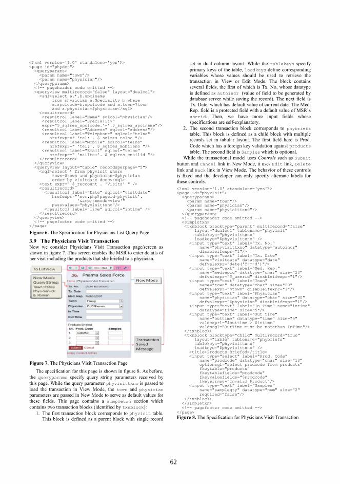
<?xml version='1.0' standalone='yes'?><page id="phydet">
<queryparams><param name="town"/><param name="physician"/>
</queryparams><!-- pageheader code omitted --><queryview multirecord="false" layout="dualcol"><sql>select a.*,b.spclname
from physician a,Speciality b wherea.spclcode=b.spclcode and a.town=$townand a.physician=$physician</sql>
<resultrecord><resultcol label="Name" sqlcol="physician"/><resultcol label="Speciality"expr="$_sqlres_spclcode.'-'.$_sqlres_spclname”/><resultcol label="Address" sqlcol="address"/><resultcol label="Telephone" sqlcol="telno"
hrefexpr=" 'tel:'. $_sqlres_telno "/><resultcol label="Mobile" sqlcol="telno"
hrefexpr=" 'tel:'. $_sqlres_mobileno "/><resultcol label="Email" sqlcol="telno"
hrefexpr=" 'mailto:'. $_sqlres_emailid "/></resultrecord>
</queryview><queryview layout="table" recordsperpage="5"><sql>select * from phyvisit where
town=$town and physician=$physicianorder by visitdate desc</sql>
<text expr=" $_reccount . 'Visits' " /><resultrecord><resultcol label="Date" sqlcol="visitdate"
hrefexpr="'mvm.php?pageid=phyvisit'.'&txmode=view'"
passvalues="phyvisittxno"/><resultcol label="Time" sqlcol="intime" />
</resultrecord></queryview><!-- pagefooter code omitted -->
</page>Figure 6. The Specification for Physicians List Query Page
3.9 The Physicians Visit TransactionNow we consider Physicians Visit Transaction page/screen asshown in figure 7. This screen enables the MSR to enter details ofher visit including the products that she briefed to a physician.
Figure 7. The Physicians Visit Transaction PageThe specification for this page is shown in figure 8. As before,
the queryparams specify query string parameters received bythis page. While the query parameter phyvisittxno is passed toload the transaction in View Mode, the town and physicianparameters are passed in New Mode to serve as default values forthese fields. This page contains a simpletxn section whichcontains two transaction blocks (identified by txnblock):
1. The first transaction block corresponds to phyvisit table.This block is defined as a parent block with single record
set in dual column layout. While the tablekeys specifyprimary keys of the table, loadkeys define correspondingvariables whose values should be used to retrieve thetransaction in View or Edit Mode. The block containsseveral fields, the first of which is Tx. No, whose datatypeis defined as autoincr (value of field to be generated bydatabase server while saving the record). The next field isTx. Date, which has default value of current date. The Med.Rep. field is a protected field with a default value of MSR’suserid. Then, we have more input fields whosespecifications are self-explanatory.
2. The second transaction block corresponds to phybriefstable. This block is defined as a child block with multiplerecords set in tabular layout. The first field here is Prod.Code which has a foreign key validation against productstable. The second field is Samples which is optional.
While the transactional model uses Controls such as Submitbutton and Cancel link in New Mode, it uses Edit link, Deletelink and Back link in View Mode. The behavior of these controlsis fixed and the developer can only specify alternate labels forthese controls.<?xml version='1.0' standalone='yes'?><page id="phyvisit">
<queryparams><param name="town"/><param name="physician"/><param name="phyvisittxno"/>
</queryparams><!-- pageheader code omitted --><simpletxn><txnblock blocktype="parent" multirecord="false"
layout="dualcol" tablename="phyvisit"tablekeys="phyvisittxno"loadkeys="$phyvisittxno" />
<input type="text" label="Tx. No."name="phyvisittxno" datatype="autoincr"disableifexpr="1"/>
<input type="text" label="Tx. Date"name="visitdate" datatype="date"defvalexpr="date('Y-m-d')"/>
<input type="text" label="Med. Rep."name="medrepid" datatype="char" size="20"defvalexpr="$_userid" disableifexpr="1"/>
<input type="text" label="Town"name="town" datatype="char" size="20"defvalexpr="$town" disableifexpr="1"/>
<input type="text" label="Physician"name="physician" datatype="char" size="30"defvalexpr="$physician" disableifexpr="1"/>
<input type="text" label="In Time" name="intime"datatype="time" size="5"/>
<input type="text" label="Out Time"name="outtime" datatype="time" size="5"valdexpr1="$outtime > $intime"valdmsg1="OutTime must be morethan InTime"/>
</txnblock><txnblock blocktype="child" multirecord="true"
layout="table" tablename="phybriefs"tablekeys="phyvisittxno"loadkeys="$phyvisittxno" />
<title>Products Briefed</title><input type="select" label="Prod. Code"
name="prodcode" datatype="char" size="10"optionsql="select prodcode from products"fkeytable="products"fkeytablefields="prodcode"fkeyvaluefields="$prodcode"fkeyerrmsg="Invalid Product"/>
<input type="text" label="Samples"name="sampleqty" datatype="num" size="2"required=”false”/>
</txnblock></simpletxn><!-- pagefooter code omitted -->
</page>Figure 8. The Specification for Physicians Visit Transaction
6262

3.10 MobiDSL MetamodelWe can see that MobiDSL has very high expressive power as itallows us to specify page structure, presentation (static/dynamictext, widgets), navigation, data retrieval, data formatting andtransactional logic at almost same level of expression as requiredin communicating the specifications to a programmer. Further, theuse of pass-through SQL enables system designers, analysts andprogrammers to leverage their knowledge to develop mobile webapplications with relative ease without any web programming.Moreover, MobiDSL allows extensibility by allowing developersto use any user-defined function in various expressions. Figure 9presents a simplified view of MobiDSL metamoddel, whichdepicts various design elements/constructs at a glance.
Figure 9. A simplified view of MobiDSL metamodel
4. Discussions4.1 Application Life-Cycle ManagementMobiDSL provides a reasonably sound framework for completelife-cycle management of mobile web applications:Prototyping: As the MobiDSL specifications are at very highlevel almost mirroring the functional requirements, it is possibleto create working prototypes using MobiDSL in similar time thatmight be needed to create a prototype using any prototyping tool.Development: MobiDSL is compact DSL designed specificallyfor mobile web applications. The constructs provided in the DSLalong with the ability to use pass through SQL and user definedfunctions make it reasonably adequate to cover most of the needs.Testing: MobiDSL code, being declarative in nature, is far easierto debug than a procedural code. Moreover, the VM allows quicktesting as the changes are reflected immediately in the application.This can save considerable time as the change-compile-build-deploy cycle is eliminated.Deployment: The VM uses basic protocols (HTTP) and basicAPI’s (CGI, pass through SQL). As a result, it can be deployed oncommodity hardware or most of the existing infrastructure in anorganization. It provides scalability by allowing multipleapplication servers, which can be added or removed without needto shut down the application. Finally, the VM does not require anyspecial middleware typically seen in many high-end applications.4.2 Generative vs. Interpretive ApproachWe believe that a carefully crafted implementation of a VM canoffer several benefits at speeds matching that of the generated
code. Whereas generated code needs to be maintained, versioned,compiled and installed on an application server, these tasks areeliminated in the interpretive approach, leading to easierdeployment and maintenance of the application.
5. ConclusionsContribution. In this paper, we have looked into the question ofhow we can simplify the development, deployment and life cyclemanagement of mobile web applications. The question isimportant because mobile web is a fast growing informationdelivery medium and it is vital for organizations to quicklydevelop systems for mobile platform with least effort. Our maincontributions can be summarized as follows:
1. Identifying core requirements and design elements ofmobile web applications
2. Designing a DSL for defining the complete specificationsof a Page/Screen
3. Incorporating the concept of using SQL in DSL for Queries4. Creating a VM to support the DSLThis research has resulted in development of a lightweight
framework consisting of MobiDSL and its associated VM. It hasbeen tested extensively by us, and was found to perform as perour design expectations on parameters such as coverage ofproblem domain, ease of development and deployment, speed ofexecution, scalability and reliability. This framework is also beingused in industry to create mobile specific versions of certain partsof their enterprise application.Future Work. MobiDSL being a nascent framework, is evolvingcontinuously. Future work includes enhancing the DSL toincrease functionality, providing client-side validations usingJavaScript (based on device capability) and conducting a detailedcomparative study of various metrics with respect to other popularweb engineering methodologies.
AcknowledgmentsWe thank the anonymous reviewers for their valuable comments.We also thank all those who have helped in this work.
References[1] Mobile Web Initiative. Available: http://www.w3.org/Mobile/[2] Mobile Web Best Practices1.0. Available:
http://www.w3.org/TR/2008/REC-mobile-bp-20080729/.[3] dotMobi Mobile Web Developer's Guide. Available:
http://mobiforge.com/starting/story/dotmobi-mobile-web-developers-guide.
[4] Instant Mobilizer. Available: http://www.instantmobilizer.com/[5] Janne Luoma,,Steven Kelly, Juha-Pekka Tolvanen : Defining
Domain-Specific Modeling Languages: Collected Experiences.Available: http://www.metacase.com
[6] Arie van Deursen, Paul Klint, Joost Visser: Domain-SpecificLanguages: An Annotated Bibliography. SIGPLAN Notices 35(6):26-36 (2000)
[7] Nunes, D. A.; Schwabe, D. : Rapid Prototyping of Web ApplicationsCombining Domain Specific Languages and Model Driven Design.in 6th International Conference on Web Engineering (ICWE’06),ACM Press, Jul. 2006.
[8] Martin Nussbaumer, Patrick Freudenstein, Martin Gaedke: TowardsDSL-based web engineering. WWW 2006: 893-894
[9] Eelco Visser: WebDSL, “A Case Study in Domain-SpecificLanguage Engineering,” in GTTSE 2007: 291-373
[10] Stefano Ceri, Piero Fraternali, Aldo Bongio: Web ModelingLanguage (WebML): a modeling language for designing Web sites.Computer Networks 33(1-6): 137-157 (2000)
[11] Atzmon Hen-Tov, David H. Lorenz, Lior Schachter: ModelTalk: AFramework for Developing Domain Specific Executable Models.CoRR abs/0906.3423: (2009)
6363

MontiWeb - Model Based Development ofWeb Information Systems
Michael Dukaczewski Dirk ReissMark Stein
Institut f. WirtschaftsinformatikAbt. Informationsmanagement
Technische Universität Braunschweighttp://www.tu-braunschweig.de/wi2
Bernhard RumpeSoftware Engineering
RWTH Aachenhttp://www.se-rwth.de
ABSTRACTThe development process of web information systems is of-ten tedious, error prone and usually involves redundant stepsof work. Therefore, it is rather efficient to employ a model-driven approach for the systematic aspects that comprisesuch a system. This involves models for the data structurethat shall be handled by the system (here: class diagrams),various editable and read-only presentations (views) on com-binations and extractions of the underlying data (here: aspecial view language) and ways to connect these views anddefine data flow between them (here: activity diagrams).
In this paper, we present the MontiWeb approach to modeland generate these aspects in a modular manner by incor-perating the MontiCore framework. Therefor we shortly in-troduce the infrastructure that helps to develop modularsystems. This involves the whole development process fromdefining the modeling languages to final code generation aswell as all steps in between. We present the text-based classand activity diagram languages as well as a view languagethat are used to model our system.
1. INTRODUCTIONThe development of web information systems is a domainthat is rather well understood. Quite a number of webapplication frameworks offer means to implement such sys-tems using a wide range of approaches in almost every mod-ern programming language (for an overview, we refer to[30]). However, most of these frameworks still demand avast amount of repetitive and tedious work to implementsimilar parts of a web application: usually a datastructureneeds to be implemented following a well-defined and under-stood scheme, same applies to the persistence mechanisms- either manually written or by using a framework such asJPA [13]. In web systems most of the datastructure needappropriate presentations to provide CRUD (create, read,update and delete) functionality and page flow needs to bedefined for each web application. Depending on the tech-nology employed, the effort needed to implement this variesa lot: frameworks like Apache Struts [2] require the main-tenance of lengthy and unreadable XML files to specify theflow between different pages.
In order to develop such a system as efficient as possibleand thus to reduce laborious and error prone work of man-ually writing the verbose code and configuration files of aweb application framework, the adoption of a model driven
approach [21, 15, 14] is usually a good choice. Abstract-ing from implementation details, the developer can focus onspecifying the essentials of the system. These are in partic-ular (1) means to define the data structure of the applica-tion, (2) ways that enable the developer to define views onthe data structure and (3) the possibility to connect theseviews and specify the relevant parts of a complete web ap-plication. From the models describing these aspects, oneor more code generators can create many necessary partsof a web-based system. Of course the discussed languagesdo not cover every aspect (e.g. complicated authenticationor application specific functionality is not covered), but thegenerators and their frameworks used provide a large partof the basic functionality.
In this paper, we present the web application modeling frame-work MontiWeb. One of the main targets of this approachis to come up with running prototypes early and refine thosein an agile way until the final system is developed. There-fore, the MontiWeb approach does provide defaults. Thediscussed generators are in particular connected to targetframeworks and components, that e.g. do provide persis-tence and a standard authentication mechanism that how-ever can be replaced and adapted to specific needs.
Generally DSLs can be designed as graphical or text-basedmodeling languages. Both have its advantages and disad-vantages. As we do not focus on graphical frontends, buton agile usability, we use a textual notation due to the ad-vantages presented in [11] and the fact that both can betransformed into eachother.
The rest of the paper is organized as follows: Section 2 intro-duces the framework we use to implement the web applica-tion modeling languages, Section 3 describes the languagesin detail, Section 4 presents related work regarding the mod-eling of web information systems and Section 5 concludesthis paper and gives an outlook of future extensions.
2. DEVELOPING DSLS USING THE MON-TICORE FRAMEWORK
As already mentioned in Section 1, we use the modelingframework MontiCore [18, 17, 19] as technological basis forMontiWeb. MontiCore is being developed at RWTH Aachenand TU Braunschweig. It allows the convenient specificationof textual modeling languages and provides an extensive in-frastructure to process these. It is designed for the rapid
64 64

development of domain specific languages. A modeling lan-guage can be defined in an integrated format that combinesboth abstract and concrete syntax in one specification.
MontiCore-Grammar
1 grammar Classviews {2
3 external Annotation;4 interface ViewElement;5
6 Classviews = Annotation* name:IDENT7 "{" Attributes? Views* "}";8
9 Modifier = (Editor:["editor"] |10 Display:["display"] | Field:["field"]);11
12 View = Annotation* Modifier name:IDENT?13 "{" ViewElement+ "}";14
15 ViewParameter implements ViewElement =16 Annotation* Modifier? name:IDENT ";";17 // ...18 }
Figure 1: Definition of AST (Metamodel) and con-crete textual syntax for Classviews
As shown in Figure 1, a grammar in MontiCore starts withthe keyword grammar and is identified by a name (here:Classviews). Non-terminals are notated on the left handside of a production (here: Classviews (6), Modifier (9),View (12) and ViewParameter (15)) and used on the righthand side. Keywords are enclosed in double-quotes whereasnamed elements have a name in front of a colon, followedby the type of element afterwards (e.g., name as the nameand IDENT as the type of the predefined terminal (6, 12)).Rules can have a cardinality (e.g. * (6, 7) for 0 to unlim-ited occurence, + (13) for 1 to unlimited and ? (7, 12, 16)for optional occurrence) and alternative rules (e.g. (9, 10),seperated by the pipe character (|)) are supported. Thekeyword external marks certain non-terminals as definedoutside of the actual grammar (3) and needs to be linked toanother non-terminal from a different grammar. The key-word interface (4) implies that the following element is aplaceholder for arbitrary elements that implement this inter-face. Here, the non-terminal ViewElement can be replacedby the non-terminal ViewParameter or further here ommit-ted non-terminals (indicated by the three dots (17)).
Besides these constructs, MontiCore supports extension mech-anisms such as grammar inheritance (see [19] for a moredetailed description of this and the abovementioned con-cepts). From the grammar, several tools for model instanceprocessing, model-to-model transformation, and code gener-ation are generated and used within the MontiWeb tool.
3. MONTIWEB - MODELING WEB APPLI-CATIONS
The difficulties with developing web information systemsmanually were briefly described in Section 1. These prob-lems mainly occur due to the application of different tech-nologies that are not designed to be used together. Fordata persistence, a relational database management system
is the common case. Modern frameworks like Struts [2] orTapestry [3] use template engines like Velocity [28], Free-marker [9] or XML for generating the presentation. Thecontroller is commonly written in a modern GPL like Java.Since all these technologies are developed independently butstill describe the same elements on different levels, changesoften need to be made in all of them. For example, if a newattribute shall be added to the data structure, all three lay-ers are affected and need to be modified. Furthermore, oftenglue code in formats such as XML configuration files needto be touched as well. Thus, a model driven developmentapproach can help a lot in these cases: convenient infrastruc-ture provided, each of these layers can be defined in its ownmodeling language and describe the appropriate matter con-cisely. Therefore, adding one field would mainly concern onemodel element and reflect into all other layers automatically.Here the order in which the models are specified is not im-portant. Modeling can be an incremental process where thedifferent models are written in parallel and independentlyof eachother and then the consistency between them can bechecked on the model level and be ensured through testedcode generation. The three modelling languages with syntaxand function in the websystem and interaction are describedin the following.
3.1 Data StructureThe central aspect of a web information system is the under-lying data structure. The language describing it should beflexible enough to express all necessary aspects and yet easyand domain specific enough to raise the level of abstractionabove manual implementation.
Three requirements for the data structure description areset: (1) A type system (2) composability and (3) relationshipbetween model elements. By a domain specific data typesystem special characteristics are assigned to the data. Thusvalidation of data, transformation rules, storage mechanismsand other data-specific functions are easily possible.
Composability of complex data means that one data struc-ture can be made up from elementary data types as well ascomplex ones defined elsewhere in the model. The relation-ships between the data define mapping properties. Sinceclass diagrams offer enough expressiveness for data model-ing and are generally well-known, MontiWeb uses a textualrepresentation of a subset of UML/P [25, 24] class diagramsto describe the data structure. In the following we explainhow the chosen modeling language met the three require-ments for the description of the data structure. An exam-ple of such notation is shown in Figure 2. It shows thesimplified data structure of a carsharing service that con-sists of persons and cars. A class diagram begins with thekeyword classdiagram and is named right after (1). It con-tains class definitions that are notated straight-forward withthe corresonding keyword. The different attributes are de-fined within the class and consist of a type (e.g. MWString
(4) which represents a domain specific implementation ofa String) and a name (e.g. name (4)). MontiWeb distin-guishes two types of classes: (a) Base classes - are similar toprimitive types of Java. They do not include any attributesand are implemented in the target system according to theirown rules. (b) Complex classes - contain attributes of baseclasses as well as other complex classes. To model relation-
65 65
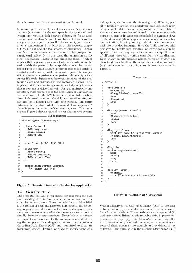
ships between two classes, associations can be used.
MontiWeb provides two types of associations. Normal asso-ciations (not shown in the example) in the generated websystem are treated as link between objects, i.e. for an asso-ciation between class A and B, an object of class A can beassigned to an object of class B. The second type of associ-ation is composition. It is denoted by the keyword compo-
sition (17-18) and the two associated classnames (Personand Car). Associations can have named roles (keeper andcars), cardinalities (* in this case, the ommission on theother side implies exactly 1) and directions (here, -> whichimplies that a person owns cars that only exists in combi-nation with the person). In compositions, one class is em-bedded into the other class, whereas the embedded object iscreated simultaneously with its parent object. The compo-sition represents a part-whole or part-of relationship with astrong life cycle dependency between instances of the con-taining class and instances of the contained classes. Thisimplies that if the containing class is deleted, every instancethat it contains is deleted as well. Using to multiplicity anddirection, other properties of the association or compositioncan be defined. In MontiWeb, static selection lists, such asdays of the week, can be defined by enumerations (9), andcan also be considered as a type of attributes. The entiredata structure is distributed over several class diagrams. Aclass diagram is an excerpt of the overall system. The sourcecode in Figure 2 shows a part of the car sharing web system.
Classdiagram
1 classdiagram Carsharing {2
3 class Person {4 MWString name;5 Email email;6 Number age;7 }8
9 enum Brand {AUDI, BMW, VW;}10
11 class Car {12 Brand brand;13 Number numSeats;14 MWDate constYear;15 }16
17 composition Person (keeper)18 -> (cars) Car [*];19 }
Figure 2: Datastructure of a Carsharing application
3.2 View StructureThe presentation layer is responsible for rendering the dataand providing the interface between a human user and theweb information system. Since the main focus of MontiWebis the domain of data-intensive web applications, the model-ing language used offers means to conveniently specify dataentry and presentation rather than extensive structures todetailly describe pretty interfaces. Nevertheless, the gener-ated layout can be altered by the common means of adjust-ing the templates for code generation and the inclusion ofCascading Style Sheets (CSS) and thus fitted to a certain(corporate) design. From a language to specify views of a
web system, we demand the following: (a) different, pos-sibly limited views on the underlying data structure mustbe specifiable, (b) views are composable, i.e. once definedviews can be composed to and reused in other ones, (c) staticparts (e.g. text or images) can be included in dynamic viewson the data and (d) web specific convenience functionalitylike validation, filtering, sorting data etc. can be modeledwith the provided language. Since the UML does not offerany way to specify such features, we developed a domainspecific Classview language which allows the specificationof different views on a certain class from a class diagram.Each Classview file includes named views on exactly oneclass (and thus fulfilling the abovementioned requirement(a)). An example of such for class Person is depicted inFigure 3.
Classviews
1 Person {2
3 attributes {4 @Required5 @Length(min=3, max=30)6 name;7 @Required8 age;9 }
10
11 display protectedMail {12 name;13 @AsImage(alt=false)14 email;15 cars;16 }17
18 display welcome {19 text {Welcome to Carsharing Service}20 include protectedMail;21 age;22 }23
24 @Captcha25 editor registration {26 name;27 email;28 age;29 cars;30 }31
32 display error {33 @Warning34 text {You are not old enough!}35 }36 }
Figure 3: Example of Classviews
Within MontiWeb, special functionality (such as the onesnoted above in (d)) is encoded in a syntax that is borrowedfrom Java annotations. These begin with an ampersand (@)and may have additional attribute-value pairs in parens ap-pended to it (e.g. (5)). For MontiWeb, we already offera rich selection of predefined domain-specific annotations -some of them shown in the example and explained in thefollowing. The rules within the element attributes (3-9)
66 66

apply to all views within the classview file. Here these im-ply that the attributes name and age are obligatory to en-ter (@Required (4, 7)) and name may appear 3 to 30 chars(@Length(min=3, max=30) (5). These result in the gener-ation of according AJAX verifictaion mechanisms. Subse-quently, the different views are specified. These begin withthe type of view (here: display (11, 18, 32) for views thatsimply output the data and editor (25) that renders theappropriate input fields for the classes’ attributes) and arefollowed by a name. The view protectedMail renders thename, email address and cars data of a person whereas theemail address is being transformed to an image (caused bythe web-specific annotation @AsImage to avoid automaticemail address harvesting). The welcome view displays somestatic text (19), does furthermore include the protected-
Mail view and displays a persons age. This functionalitysatisfies the demands (b) and (c) from above. The reg-
istration view is an editor view and thus provides inputfields for name, email and age of a person and – as cars
denotes the composition of car objects within a person –means to associate such objects to a person. The annota-tion @Captcha (24) produces a captcha field on this view.Finally, the view error (32-35) simply consists of a statictext that is rendered in a manner that indicates a warning.
An example of how the registration view could be ren-dered is shown in Figure 4.
Figure 4: View ”editor”
3.3 Control- and DataflowDefining only the data structure and different views on itsuffices for generating basic web information systems thatallow rudimentary data manipulation functionality like en-tering and saving, showing and updating the data. To createmore complex web applications, we need means to modelboth, control and data flow between the different pages orviews respectively. For this purpose, we use a profile of UMLactivity diagrams [22] in textual notation. An example of anactivity diagram is shown in Figure 5. It describes a processof user registration where a user enters his user data and isthen directed to either a welcome page (in case his age isgreater than 18) or an error page (if the age is smaller than18).
An activity diagram starts with the keyword activity fol-lowed by the activities’ name (here: UserRegistration).Actions (introduced by the keyword action (3, 8, 13)) posses
Activity Diagram
1 activity UserRegistration {2
3 action Registration {4 out: Person p;5 view : p = Person.registration();6 }7
8 action Welcome {9 in: Person p;
10 view : Person.welcome(p);11 }12
13 action Error {14 in: Person p;15 view : Person.registrationError(p);16 }17
18 initial -> Registration;19 Registration.p -> [p.age >= 18] Welcome.p20 | [p.age < 18] Error.p;21 Welcome | Error -> final;22 }
Figure 5: Example of Activity Diagrams
a name as well and include different contents: in (9, 14) andout (4) followed by an attribute type (Person) and attributename (p) specify input and output parameters of an action.The keyword view (5, 10, 15) indicates the kind of contentof an action. The view itself is referenced by its name and ei-ther can take an object as argument (10, 15) to initialize theview or return an object which is assigned to an output pa-rameter (5). Transitions within an activity are representedby an arrow symbol (-> (18, 19, 21)) and may contain sev-eral sources and targets. The keywords initial and final
denote start and final nodes of an activity and the pipe char-acter (| (20, 21)) depicts alternative flows - with conditionson the right hand side (19, 20) or as alternative routes to thefinal node (21). Object flow is modeled by appending theparameter name to the action name and for simple controlflow, these parameters are left out.
Besides these notation elements, concepts such as parallelflow, hierarchical actions (which themselves are specified byan activity) and roles to which actions can be assigned aresupported as well but omitted in this paper for the sake ofspace. Furthermore, different content can be included in anaction. Presently, the inclusion of Java code is supportedalong the already mentioned view calls.
3.4 Aggregation (Interaction) of ComponentSpecific Languages
The described models define three views on a whole system.They are developed and specified independently from eachother to maintain clean seperation of the different compo-nents. Nevertheless the model parts have some well-definedconnection points. Elements that are defined in one modelare referenced from another (e.g., views are referenced froman action). The inter-model-relationships are essential forcompleteness and correctness of the whole system and fi-nally define its behavior.
67 67

When developing modeling languages from scratch for partsof a domain, first and foremost only these parts are con-sidered. However, although they will work in isolation, theyare often used in combination to model the complete system.Therefore, the notation of a language must provide meansto connect to other components.
Interaction between modeling languages can be realized withdifferent mechanisms [26], e.g. by embedding one languageinto another like SQL is embedded into a GPL like Java. InMontiWeb, the inter-language interaction is realized by us-ing the pipeline pattern [26]. There, the different languagesare independent but still implicitly connected, i.e. the im-plicit relationships are explicitly checked within the genera-tion process. The visibility between the MontiWeb modelsis depicted in Figure 6. The controller functionality is real-ized similar to the Application Controller pattern [8]. Here,class diagrams are completely independent from the rest ofthe model. Neither the data presentation (classviews) northe flow control (activity diagrams) are of importance for thedata definition and thus can not be referenced from there.Classviews depend on the data structure as they define ex-plicit views thereof and contain references (e.g. to class-names, attribute names and types or association names) toit. Classviews do not reference activity diagrams, vice versaactivity diagrams reference classviews by name. As the con-trol flow defines the central logic of a web information sys-tem, both class diagrams and classviews are referenced fromthere. To maintain consistency between these models, inter-model checks are performed through, e.g. modular symboltables. Thus the existence of a referenced view or class canbe verified.
Activitydiagram
Classdiagram Classviews
Figure 6: Models of MontiWeb and their dependen-cies
4. RELATED WORKSimilar approaches of modeling of web information systemscan be classified into (a) modeling using graphical languages,and (b) modeling using textual languages.
One graphical modeling tool in the domain of web informa-tion systems is WebML. Unlike MontiWeb, WebML distin-guishes two domain segments: (a) data design concerns thespecification of data structures and (b) hypertext design isused to describe the structure of web pages [6]. Both of theselanguages incorporate UML class diagrams. For hypertextdesign, predefined classes like Entry for the generation of aweb form or Data to display a class are used. The naviga-tion structure is depicted by directed associations between
classes. Furthermore, WebML supports a XML based tex-tual modeling language which lacks tool support. Therefore,the use of their own graphical modeling tool is favored [5].
UWE (UML-based Web Engineering) [16] follows a similarapproach as WebML. It uses class diagrams for data struc-ture specification and, like MontiWeb, uses acivity diagramsto describe the modeling of workflow. UWE’s notation is agraphical one as well. Like WebML, the UWE models canbe exported in an XML format.
Another tool that uses graphical modeling is AndroMDA [1].AndroMDA does not have its own editor yet, but uses XMIas input format which is supported by some UML Editors.Like MontiWeb, it uses class diagrams for data structureand activity diagrams for workflow description. AndroMDAdoes not offer a specific language to describe the view aspectof a web information system, but generates it from extraclass diagrams that have to be specified additionally. Toget a working application, all parts have to be provided. Ageneration of standard behavior as MontiWeb does is notsupported.
As a textual modeling approach, WebDSL [29] follows a sim-ilar approach as MontiWeb. The language there is specifiedusing SDF [12] and Stratego/XT [4] for language transfor-mation. They use a purely domain specific modeling lan-guage and is not leaned on UML.
The Taylor project [27] follows an MDA approach to modeland develop JEE applications. The models are created usingEclipse Graphical Modeling Framework (GMF) [10] and arestored in XMI format by incorporating EclipseUML [7]. Asnotation for data structure, Taylor uses class diagrams, busi-ness processes are defined by activity diagrams as well. Thenavigation structure between pages is specified by a statemachine language where states depict pages and transitionslinks from page to page.
Another popular approach for generating web informationsystems is Ruby on Rails [23]. Although it is not a puremodel based approach, a prototype application can be gen-erated using the Ruby on Rails scaffold mechanism. From asimple model in a Rails-specific notation and a HTML-basedview template language, CRUD functionality and a very ba-sic controller can be generated. However, unlike MontiWeb,the focus of Rails is the manual programming of all threecomponents, aided by extensive web-specific functionalityprovided by the language.
The Mod4j (Modeling for Java) [20] project aims at the effi-cient development of administrative enterprise applicationsby employing a model driven approach. Like MontiWeb,Mod4j seperates the application into its different aspects andoffers a modeling language for each. The Business DomainModel is represented by an UML class diagram. Page flow ismodeled using a specific Service Model and the presentationin the application has its own modeling language as well.Mod4j is based on Eclipse technology and uses XText [31]for the development of languages.
68 68

5. CONCLUSION AND FUTURE WORKIn this paper we described our approach to model and gen-erate web information systems to tackle the insufficiencesthat occur when developing such systems manually. Espe-cially the difficulties caused by the combination of normallyorthogonal frameworks are approached. Within MontiWeb,we use three languages for the three main segments of a webinformation system. Two of them come from the UML/P,one language (classviews) is completely new defined. Theselanguages reflect the requirements of each domain compo-nent and were adapted to their specific needs.
The currently reached status involves pretty stable languages,as discussed here, and appropriate generation tools. Fur-thermore a number of presentation forms for various datatypes (such as Date, String etc. are defined). We cur-rently work on extensions of the provided functionality invarious ways. This includes e.g. components for more finegrained security, identification and authentication as well asthe possibility to easily integrate predefined (third-party)components that provide application specific functionality.We plan to further extend and complete the already usedlanguages (e.g. include inheritance in class diagrams) andincorporate new ones to model not yet covered aspects ofa web information system (such as use case diagrams forrequirements modeling). Furthermore, we think of genera-tion of a modular API to access the generated system viaSOA-services or add SOA-functionality provided by otherservers.
6. REFERENCES[1] AndroMDA Homepage http://www.andromda.org/.
[2] Apache Struts Homepagehttp://struts.apache.org/.
[3] Apache Tapestry Homepagehttp://tapestry.apache.org/.
[4] M. Bravenboer, K. T. Kalleberg, R. Vermaas, andE. Visser. Stratego/XT 0.17. A Language and Toolsetfor Program Transformation. Science of ComputerProgramming, 72:52–70, 2008.
[5] S. Ceri, P. Fraternali, and A. Bongio. Web ModelingLanguage (WebML): a modeling language fordesigning Web sites. Computer Networks,33(1-6):137–157, June 2000.
[6] S. Ceri, P. Fraternali, and M. Matera. Conceptualmodeling of data-intensive web applications. IEEEInternet Computing, 6(4):20–30, 2002.
[7] Eclipse UML Projecthttp://www.eclipse.org/modeling/mdt/?project=uml2.
[8] M. Fowler. Patterns of Enterprise ApplicationArchitecture. Addison-Wesley, 2003.
[9] Freemarker Website http://freemarker.org/.
[10] Graphical Modeling Framework Website.http://www.eclipse.org/gmf/.
[11] H. Gronniger, H. Krahn, B. Rumpe, M. Schindler, andS. Volkel. Textbased Modeling. In 4th InternationalWorkshop on Software Language Engineering, 2007.
[12] J. Heering, P. R. H. Hendriks, P. Klint, and J. Rekers.The syntax definition formalism SDF - ReferenceManual. Sigplan Notices, 24(11):43–75, 1989.
[13] Java Persistence API http://java.sun.com/javaee/-technologies/persistence.jsp.
[14] S. Kelly and J.-P. Tolvanen. Domain-SpecificModeling: Enabling Full Code Generation. Wiley,2008.
[15] A. G. Kleppe, J. Warmer, and W. Bast. MDAExplained: The Model Driven Architecture: Practiceand Promise. Addison-Wesley Longman PublishingCo., Inc., Boston, MA, USA, 2003.
[16] N. Koch and A. Kraus. The expressive power ofUML-based engineering. In Second InternationalWorkshop on Web Oriented Software Technology(CYTED), 2002.
[17] H. Krahn, B. Rumpe, and S. Volkel. Efficient EditorGeneration for Compositional DSLs in Eclipse. InProceedings of the 7th OOPSLA Workshop onDomain-Specific Modeling 2007, 2007.
[18] H. Krahn, B. Rumpe, and S. Volkel. IntegratedDefinition of Abstract and Concrete Syntax forTextual Languages. In Proceedings of Models 2007,pages 286–300, 2007.
[19] H. Krahn, B. Rumpe, and S. Volkel. Monticore:Modular development of textual domain specificlanguages. In Proceedings of Tools Europe, 2008.
[20] Mod4j Homepage http://www.mod4j.org/.
[21] Object Management Group. MDA Guide Version 1.0.1(2003-06-01), June 2003.http://www.omg.org/docs/omg/03-06-01.pdf.
[22] Object Management Group. Unified ModelingLanguage: Superstructure Version 2.1.2 (07-11-02),2007. http://www.omg.org/docs/formal/07-11-02.pdf.
[23] Ruby on Rails Website http://rubyonrails.org.
[24] B. Rumpe. Agile Modellierung mit UML :Codegenerierung, Testfalle, Refactoring. Springer,2004.
[25] B. Rumpe. Modellierung mit UML. Springer, 2004.
[26] D. Spinellis. Notable Design Patterns for DomainSpecific Languages. Journal of Systems and Software,56(1):91–99, Feb. 2001.
[27] Taylor Homepage (http://taylor.sourceforge.net/).
[28] Velocity Website http://velocity.apache.org/.
[29] E. Visser. WebDSL: A Case Study in Domain-SpecificLanguage Engineering. Technical ReportTUD-SERG-2008-023, Delft University of Technology,Software Engineering Research Group, 2008.
[30] I. Vosloo and D. G. Kourie. Server-Centric WebFrameworks: An Overview. ACM Computing Surveys,40(2):1–33, 2008.
[31] Xtext Homepage http://www.eclipse.org/Xtext/.
69 69

ProcDSL + ProcEd - a Web-based Editing Solutionfor Domain Specific Process-Engineering
Christian Berger Tim Gülke
RWTH Aachen UniversitySoftware Engineering Group
Ahornstraße 5552074 Aachen, Germany
www.se-rwth.de
Bernhard Rumpe
ABSTRACTIn a high-tech country products are becoming rapidly morecomplex. To manage the development process as well as toencounter unforeseen challenges, the understanding and thusthe explicit modeling of organizational workflows is more im-portant than ever. However, available tools to support thiswork, in most cases force a new notation upon the companyor cannot be adapted to a given publication layout in a rea-sonable amount of time. Additionally, collaboration amongcolleagues as well as different business units is complicatedand less supported. Since it is of vital importance for acompany to be able to change its processes fast and adaptitself to new market situations, the need for tools support-ing this evolution is equally crucial. In this paper we presenta domain specific language (DSL) developed for modeling acompany’s workflows. Furthermore, the DSL is embedded ina web-based editor providing transparent access using mod-ern web 2.0 technologies. Results of the DSL’s as well asthe editor’s application to document, model, and improveselected workflows of a German automotive manufacturerare presented.
1. INTRODUCTION AND MOTIVATIONIn today’s world of business-processes, modeling becomes avital factor in an organization’s change and process man-agement and even daily routines. This in particular holdsfor the development of complex machines, such as airplanes,cars or trains. Each of these domains has their own specificproblems, e.g. induced through supplier integration, need forquality certification, development for individual customersor the mass market, etc.
It is therefore not surprising that there is no unique solu-tion for the management of these processes. Therefore, itis only natural to find company-specific layouts of process-descriptions and publications in almost every firm. Unfor-
tunately, tools meant to support organizations in planningand developing their processes, often force their own layout,notation and logic upon their users. Although this might beconsidered easier and even ’better’ than what the companyis used to, we found it is one main reason to see printed Mi-crosoft PowerPoint slides and similar documents to arise allover office walls. Big organizations need a certain amountof time to agree on a specific appearance of their process-documents and even longer to publicize this throughout thecompany. And even worse, the meaning of icons or the posi-tion of images tends to change during a company’s evolution.Programs like [6] or [2] are not able to be easily adapted toappear like what people know and have worked with already.This fact clearly shows the need for a modular tool whichcan be adapted with considerably less effort than any othersavailable.
Furthermore, many currently available tools are single userapplications with only limited possibility for company-widecollaboration. Using MontiCore [5], a framework for devel-oping domain specific languages, we developed a web-basededitor for modeling organizational workflows that uses aDSL’s instances as input and output. This DSL was de-veloped together with company-experts to ensure correct-ness and completeness. The editor’s interface then was con-structed separately, so there was a clean cut between thelogic and its representation. This enables us to change ei-ther the logic behind a process-plan or the frontends’ ap-pearance without touching the other. Process modeling isthen being performed by the end user through a web-browserto gain the amount of flexibility necessary in today’s quicklychanging world. AJAX technology enables us to constructan interface almost as powerful as a traditional application’sone.
This paper is structured as follows. First, a brief overviewof MontiCore is presented. Following, the design consider-ations and the implementation of a DSL to model organi-zational workflows are discussed. This DSL is embedded ina web-based process editor which is presented afterwards.Finally, the DSL as well as the editor’s application is shownon an example from the automotive domain.
70 70

2. MONTICORE – A FRAMEWORK FORDEVELOPING DOMAIN SPECIFIC LAN-GUAGES
MontiCore is a framework for developing textual domainspecific languages from the Department of Software Engi-neering at RWTH Aachen University. It supports grammar-based language design as well as meta-modeling conceptsby providing one language for abstract and concrete syntaxdefinition. Using a given definition it generates automati-cally a lexer, a parser, and classes for an abstract syntaxgraph (ASG) describing the language’s structure. At run-time, these classes represent a successfully parsed and pro-cessed instance of a given language [5, 7, 8, 9].
Generated artifacts and MontiCore itself are coded in Java.Due to its sophisticated language processing concepts andits support for Java which is also used by the technologywe intended to use for realizing the web-based editor, wehave chosen MontiCore for defining the language and forprocessing instances at runtime.
3. PROCDSL – A DSL FOR PROCESS DE-SCRIPTIONS
We propose a domain specific language to represent the com-pany’s organizational workflow processing. The reason weused a DSL to formalize the logic behind a process-planwas the complex structure of those plans, hidden behind arather simple appearance. Basically, a milestone’s appear-ance in a specific plan was determined by the organizationalview, consisting of a layer and unit combination, the planrepresented. One unit might be only participating to themilestone’s result while another one is responsible for it.Both types of access are represented through different iconsin their unit’s process-plan.
Without the use of MontiCore and a DSL, we would onlyhave been able to construct an application that suits thecurrent needs and requirements as we understood them.In case of a sudden change of the appearance or logic ofthose process-plans, the application would have to be re-constructed in a time-consuming way. Through our sepa-ration it is now possible to change either the model or thegraphical representation without touching the other. TheDSL, which we modeled together with chosen experts, en-abled us to already start the development of the editor-frontend while still being in the process of figuring out thelogic’s details behind the plans. This will also save resourceslater if for example different views will be needed for thesame data. We predict that in near future, a plan’s lay-out will change again or a new organizational layer mightbe implemented - in that case the model or the editor canbe changed quickly without the need to rewrite a wholedatabase scheme and an applications access to it.
The main advantage over pure visual process modeling toolsis its formal specification. Additionally, a textually definedDSL can be simply embedded in different contexts and there-fore easily reused. In the following, we present briefly theDSL we designed for modeling organizational workflows con-sidering the following design criteria.
• Intuitional Representation. Instead of using XML fordefining workflows we chose a much more simple repre-sentation to avoid XML’s verbosity and redundancy inits data description. Thus, a better readability for theuser can be achieved if DSL’s instances are processedwithout a graphical editor.
• Small Data Format. Since the language is intendedto be used in a web-based context, large entities oforganizational workflow descriptions would cause lotsof bandwidth consumption. Thus, a small data formatto be exchanged with a server is desirable.
• Reusability. The language itself is primarily intendedto be used with a graphical web-based editor to sup-port process engineers. However, having a formally de-fined and application-independent process description,language’s instances can be easily exchanged amongthe same application. Moreover, other tools can beused for checking semantic constraints on the one handor to transform an instance into another data formaton the other hand.
• Versioning. Regardless if an available solution likeSubversion is used or a domain-specific (e.g. graphical)one is programmed it is obvious that textual formatsare easier to put under version control as well to trackand compare changes.
To ensure usefulness, domain experts from the companywere heavily involved in the development of the DSL. Us-ing a simple UML-representation of the DLS’s structure, wewere able to communicate in a productive way.
In Fig. 1, an excerpt of our grammar is shown. Technically,MontiCore accepts productions with EBNF-like right handsides. Nonterminals (like Milestone or String) can be pre-ceded by attribute names (like in name:String). Attributenames can also be attached to terminals like "Scope" or"resp" denoting, whether the keyword was detected.
Lines 1-5 contain the grammar’s start symbol. The work-flow description starts with a header containing some meta-information about the current instance followed by a list ofmilestones. Every milestone has a name, a description, andseveral other properties of which some are included in 1,lines 9-13. Line 11 positions the milestone relatively to atimeline. As already mentioned, the need to separate thelogic behind a process-plan and it its actual graphical rep-resentation was crucial. Therefore, during development ofthe DSL, we made sure not to mix graphical informationlike icon positions, colors, and the like with logic-relatedthings. As a result, an instance of the given DSL does notonly represent a milestone-plan like the one shown in Fig.4which was used as a blueprint for the DSL, it also enablesdevelopers to get different graphical representations out ofit (e.g. simple lists of milestones, a specific view on inputsand outputs of a milestone or the involvement of a layer inprocess activities).
Besides an informal description, a milestone has a concreteresult which can be any appropriate artifact depending ona specific workflow. Different scopes and layers can access
71 71

MontiCore-Grammar
1 ProcessFile =2 "process"3 ProcessHeader4 :Milestone*5 Process6 :Scope*7 "end";8 ...9 Milestone = "milestone" Name
10 ...11 "position" TimelinePosition:Number12 "result" Result:Result*13 "description" Description:String;14 ...15 Scope = "scope" Name16 "description" Description:String17 r:Responsibility*;18
19 Responsibility = "responsibility"20 (responsible:["resp"]21 | contributing:["cont"]22 | noticing:["noti"])23 "asmilestone" asMilestone:STRING;24 ...25 associations {26 Responsibility.milestone * -> 1 Milestone;27 }28
29 concept sreference {30 ResponsibilityMilestone:31 Responsibility.asMilestone = Milestone.name;32 }
Figure 1: Excerpt of our grammar to describe orga-nizational workflows.
a milestone in different ways, like being responsible or justcontributing to the result. In this case, a scope is a spe-cific organizational unit within a layer, like manufacturingwithin the layer departments. Combined, these selectionsdefine different views on the whole set of milestone-data. Ascope’s responsibilities are described in lines 19-23. Everyscope is either directly responsible for fulfilling a sub-processassociated with this milestone, contributing for a concretemilestone or only noticing the state of a sub-process.
Using the concept of automatically set associations providedby MontiCore in line 25-32, the responsibilities’ milestonesare navigably associated with an ASG node describing amilestone. The following lines starting at line 27 describethe way a milestone is mapped by its (unique) name to thecorresponding responsibility-object’s association.
For validating given values of concrete DSL’s instances ob-ject which traverses the ASG, generated by MontiCore canbe defined. For example, a time-validating visitor can beused to check the semantic constraints whether the starttime of a given milestone is prior to its end time regardingto the underlying timeline specification, which can be eithera regular calendar or a simple sequence of weeks.
Using the grammar outlined in this section, we designed andimplemented a graphical web-based editor which is describedin the following.
4. GRAPHICAL EDITOR FOR PROCDSLUSING WEB 2.0 TECHNOLOGIES
We wanted the graphical editor to be as easily usable as pos-sible combined with the flexibility a web-application gives usregarding deployment and maintenance. AJAX enables de-velopers to design web-applications that make use of asyn-chronous callbacks rather than of synchronized ones. There-fore, the traditional request-response-paradigm is no longerthe limiting factor in a web-application’s interface. UsingAJAX different parts of the website can be loaded dynami-cally providing a great range of possibilities to the developerto design the application. For more information about theAJAX technology see [12].
Since the overall layout was already fixed due to the fact thatwe were working with a company which had already specifiedits appearance for process descriptions, it was clear that theeditor should not be a generic canvas, but an aid to workin that given layout. However, it should use the formalismprovided with the DSL to keep users from inventing newicons and limit them to correct instances.
We selected the Google Web Toolkit[4] as our main frame-work which enabled us to write Java-code instead ofJavaScript for the web-interface. Through this, a highly in-teractive web-based application combined with proper test-ing and a decent coding-style was possible with much lesseffort than a traditional one would have required. The imple-mentation of Drag&Drop-capabilities as displayed in Fig.2for canvas-objects as well as dialog-windows is another factorthat makes the interface a lot more comfortable for users.Through asynchronous callbacks, drafts can be saved andrestored automatically.
As one can see in Fig.3, the main window is divided in threedifferent areas. The largest is used by the actual milestone-plan, while the other two keep a toolbox to drag objectsout from onto the plan and an object-inspector. The latterallows users to look into a chosen item’s details. To selectan object on the plan, it can simply be clicked on.
Figure 2: Web-based dragging and dropping of itemsand collections of items.
72 72

As input and output, an instance of the above defined gram-mar is used. After upload, the ASG is constructed fromthe file through the MontiCore-generated tools, althoughthese objects are kept separate from the ones behind thedisplayed items. This separation enables us to replace bothsides, grammar-generated objects and data-objects, with-out changing much at the corresponding one in case anengineering- or design-related update is necessary. No in-stance of an ASG-object is kept in a visualizable one andvice versa to achieve a very clean separation between thetwo worlds. Since the editor does not get any display-relatedinformation from the grammar, it has to decide itself on thepositioning and use of visual elements such as icons, colors,etc.
To keep everything synchronized and to reduce computa-tional effort and bandwidth, a central class containing ahashmap keeps all objects and links them to an icon-filethat the user will finally see. This pattern makes searchingand working in general with the data easier as if ASG-objectswould keep their visualized counterparts themselves instead.A Command-pattern makes sure user-input is handled cor-rectly and distributed to the right object and also adds anundo-/redo-functionality to the editor.
The web-application itself is secured through an SSL-connec-tion and a required login provides a user-environment thatlets a user keep a list of files he is working on. This part ofthe application could be extended, for example with func-tions like shared comments.
Figure 3: Screenshot of ProcEd, a web-based editorfor instances of ProcDSLs.
5. APPLICATION AT AN AUTOMOTIVEMANUFACTURER
The already fixed layout of graphical representations of thecorporate processes made questions about the application’sappearance simple. The requirements gathered for this yiel-ded to a login-screen, traditional file-menus, etc. Exampleprocess files in Microsoft Power Point like the one shownin Fig.4 specified the canvas’ layout. The real difficultiestherefore lay in the business-objects model and the differentinfluences the classes have on each other.
We used a graphical representation of our model to be ableto discuss it with selected domain-experts who had no edu-cation in computer science. UML was a good choice due toeasily understandable class diagrams. However, we neededseveral iterations to get to a complete model-specification.
The clearly separated parts in the software though made iteasy for us to keep up an agile workflow. While we couldimplement more and more of the interface, the model itselfcould be improved independently only requiring to gener-ate a new lexer and parser using MontiCore to process themodified version, and correct a function call or the like inthe separated part. Compared to a traditional approachwhich would have forced us to complete the model first andthen build the application depending on it; using the afore-mentioned approach we used during development we simplycould not only integrate but also embrace changes desiredby the customer [1].
Figure 4: Elements for process description at a Ger-man automotive manufacturer.
6. RELATED WORKThe usage of DSLs in web-applications has received increasedinterest in the last years. But as outlined in [10] or [11],these activities did only focus on modeling an application’sarchitecture and related workflows.
Our approach is different, because we did not use the DSLto define workflows, but to get a data exchange format thatalso serves as business layer in the resulting application. Achange in the DSL would not result in a whole new appli-cation layout, only in differently working interfaces, leav-ing the former with the customer agreed on GUI intact.This is crucial, since the organizational layout for process
73 73
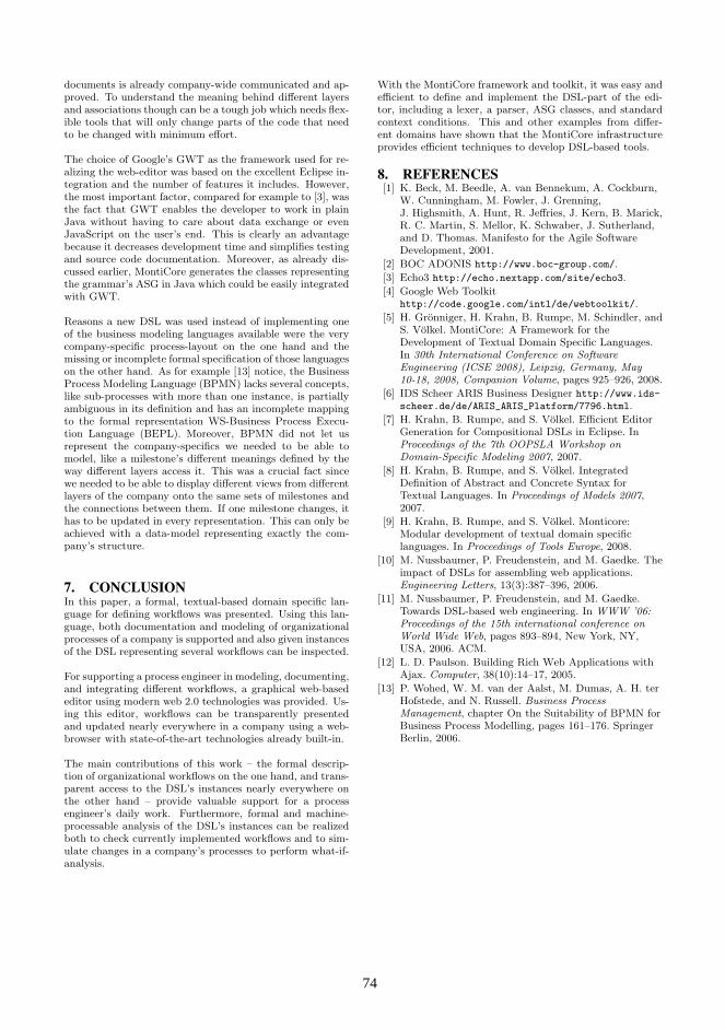
documents is already company-wide communicated and ap-proved. To understand the meaning behind different layersand associations though can be a tough job which needs flex-ible tools that will only change parts of the code that needto be changed with minimum effort.
The choice of Google’s GWT as the framework used for re-alizing the web-editor was based on the excellent Eclipse in-tegration and the number of features it includes. However,the most important factor, compared for example to [3], wasthe fact that GWT enables the developer to work in plainJava without having to care about data exchange or evenJavaScript on the user’s end. This is clearly an advantagebecause it decreases development time and simplifies testingand source code documentation. Moreover, as already dis-cussed earlier, MontiCore generates the classes representingthe grammar’s ASG in Java which could be easily integratedwith GWT.
Reasons a new DSL was used instead of implementing oneof the business modeling languages available were the verycompany-specific process-layout on the one hand and themissing or incomplete formal specification of those languageson the other hand. As for example [13] notice, the BusinessProcess Modeling Language (BPMN) lacks several concepts,like sub-processes with more than one instance, is partiallyambiguous in its definition and has an incomplete mappingto the formal representation WS-Business Process Execu-tion Language (BEPL). Moreover, BPMN did not let usrepresent the company-specifics we needed to be able tomodel, like a milestone’s different meanings defined by theway different layers access it. This was a crucial fact sincewe needed to be able to display different views from differentlayers of the company onto the same sets of milestones andthe connections between them. If one milestone changes, ithas to be updated in every representation. This can only beachieved with a data-model representing exactly the com-pany’s structure.
7. CONCLUSIONIn this paper, a formal, textual-based domain specific lan-guage for defining workflows was presented. Using this lan-guage, both documentation and modeling of organizationalprocesses of a company is supported and also given instancesof the DSL representing several workflows can be inspected.
For supporting a process engineer in modeling, documenting,and integrating different workflows, a graphical web-basededitor using modern web 2.0 technologies was provided. Us-ing this editor, workflows can be transparently presentedand updated nearly everywhere in a company using a web-browser with state-of-the-art technologies already built-in.
The main contributions of this work – the formal descrip-tion of organizational workflows on the one hand, and trans-parent access to the DSL’s instances nearly everywhere onthe other hand – provide valuable support for a processengineer’s daily work. Furthermore, formal and machine-processable analysis of the DSL’s instances can be realizedboth to check currently implemented workflows and to sim-ulate changes in a company’s processes to perform what-if-analysis.
With the MontiCore framework and toolkit, it was easy andefficient to define and implement the DSL-part of the edi-tor, including a lexer, a parser, ASG classes, and standardcontext conditions. This and other examples from differ-ent domains have shown that the MontiCore infrastructureprovides efficient techniques to develop DSL-based tools.
8. REFERENCES[1] K. Beck, M. Beedle, A. van Bennekum, A. Cockburn,
W. Cunningham, M. Fowler, J. Grenning,J. Highsmith, A. Hunt, R. Jeffries, J. Kern, B. Marick,R. C. Martin, S. Mellor, K. Schwaber, J. Sutherland,and D. Thomas. Manifesto for the Agile SoftwareDevelopment, 2001.
[2] BOC ADONIS http://www.boc-group.com/.
[3] Echo3 http://echo.nextapp.com/site/echo3.
[4] Google Web Toolkithttp://code.google.com/intl/de/webtoolkit/.
[5] H. Gronniger, H. Krahn, B. Rumpe, M. Schindler, andS. Volkel. MontiCore: A Framework for theDevelopment of Textual Domain Specific Languages.In 30th International Conference on SoftwareEngineering (ICSE 2008), Leipzig, Germany, May10-18, 2008, Companion Volume, pages 925–926, 2008.
[6] IDS Scheer ARIS Business Designer http://www.ids-
scheer.de/de/ARIS_ARIS_Platform/7796.html.
[7] H. Krahn, B. Rumpe, and S. Volkel. Efficient EditorGeneration for Compositional DSLs in Eclipse. InProceedings of the 7th OOPSLA Workshop onDomain-Specific Modeling 2007, 2007.
[8] H. Krahn, B. Rumpe, and S. Volkel. IntegratedDefinition of Abstract and Concrete Syntax forTextual Languages. In Proceedings of Models 2007,2007.
[9] H. Krahn, B. Rumpe, and S. Volkel. Monticore:Modular development of textual domain specificlanguages. In Proceedings of Tools Europe, 2008.
[10] M. Nussbaumer, P. Freudenstein, and M. Gaedke. Theimpact of DSLs for assembling web applications.Engineering Letters, 13(3):387–396, 2006.
[11] M. Nussbaumer, P. Freudenstein, and M. Gaedke.Towards DSL-based web engineering. In WWW ’06:Proceedings of the 15th international conference onWorld Wide Web, pages 893–894, New York, NY,USA, 2006. ACM.
[12] L. D. Paulson. Building Rich Web Applications withAjax. Computer, 38(10):14–17, 2005.
[13] P. Wohed, W. M. van der Aalst, M. Dumas, A. H. terHofstede, and N. Russell. Business ProcessManagement, chapter On the Suitability of BPMN forBusiness Process Modelling, pages 161–176. SpringerBerlin, 2006.
74 74

Model-View-Controller Architecture SpecificModel Transformation
Hiroshi KazatoTokyo Institute of Technology /
NTT DATA CORPORATIONTokyo 152–8552, Japan
Rafael WeißTokyo Institute of Technology
Tokyo 152–8552, [email protected]
Shinpei HayashiTokyo Institute of Technology
Tokyo 152–8552, [email protected]
Takashi KobayashiNagoya University
Nagoya 464–8601, [email protected]
Motoshi SaekiTokyo Institute of Technology
Tokyo 152–8552, [email protected]
ABSTRACTIn this paper, we propose a model-driven development techniquespecific to theModel-View-Controllerarchitecture domain. Eventhough a lot of application frameworks and source code generatorsare available for implementing this architecture, they do depend onimplementation specific concepts, which take much effort to learnand use them. To address this issue, we define a UML profile tocapture architectural concepts directly in a model and provide abunch of transformation mappings for each supported platform, inorder to bridge between architectural and implementation concepts.By applying these model transformations together with source codegenerators, our MVC-based model can be mapped to various kindof platforms. Since we restrict a domain into MVC architectureonly, automating model transformation to source code is possible.We have prototyped a supporting tool and evaluated feasibility ofour approach through a case study. It demonstrates model transfor-mations specific to MVC architecture can produce source code fortwo different platforms.
Categories and Subject DescriptorsD.2.2 [Software Engineering]: Design Tools and Techniques—Object-oriented design methods; D.2.11 [Software Engineering]:Software Architectures—Domain-specific architectures, Patterns;D.4.7 [Operating Systems]: Organization and Design—Interac-tive systems
General TermsDesign, Languages
KeywordsModel-Driven Development, Model Transformation, Model-View-Controller Architecture, UML Profile
1. INTRODUCTIONModel-driven development (MDD) [16] is a development para-
digm, which places models as primary artifacts and derives exe-cutable software by means of model transformation. It aims toincrease productivity, maintainability and reusability of models byraising the level of abstraction above general-purpose programmingand modeling languages. Some MDD tools, such as openArchi-tectureWare (oAW) [18] and AndroMDA [1], use their own UMLprofiles to include their necessary information into UML models.Since this kind of tools transform profiled UML models into sourcecode, hereafter we refer to them as (model-driven) code genera-tors. Along with the recent evolution in model transformation tech-niques, they have shown the possibility and effectiveness of MDDin practice to some extent.
However, because of the diversity of implementation platformsand code generators, there are a lot of UML profiles correspondingto various implementation concepts, and thus it is a labor-intensiveand error-prone task to build, maintain and reuse these models. Tocope with these problems, we should think of another level of ab-straction by identifying similarities of various kind of implementa-tion platforms and using code generators as building blocks.
In this paper, we propose a model-driven approach called AC-CURATE, in which theModel-View-Controllerarchitecture styleis used to capture design concepts in a user-interactive applica-tion as well as to classify implementation platforms such as ap-plication frameworks and libraries. More specifically, we define aUML profile to describe architectural concepts directly in a model.Using this profile as a pivot [3], a bunch of transformation map-pings is provided for each supported platform, in order to bridgebetween architectural and implementation concepts. By applyingthese mappings and code generators in sequence, our MVC-basedmodel can be transformed into implementation models and sourcecode for various platforms. Automating these transformations isfeasible because we only cover a restricted architecture domain.The main contribution of this paper is to propose a model-drivenapproach specific to theModel-View-Controllerarchitecture.
The rest of this paper is organized as follows. In the next sectionwe explain our motivation by a brief example. Section 3 presentsthe ACCURATE approach. Section 4 briefly introduces the proto-type implementation of our toolkit and following Sect. 5 evaluatesthe approach through a case study of an address book application.In Sect. 6, we survey some related works and close with conclusionand future work in Sect. 7.
75 75

(a) EJB Profile (b) Spring and Hibernate Profiles
Figure 1: PSM Examples Using Profiles for the Fornax-Platform [10]
2. MOTIVATING EXAMPLEClass diagrams shown in Fig. 1 are examples taken from two
different platform specific models (PSMs), one uses a profile forEJB and the other does a combination of profiles for the SpringFramework and Hibernate. Both of them specify almost same func-tionality, i.e. object/relational mapping between Java and relationaldatabases, but they are different from a technical view because oftheir platform-specific profiles.
A problem occurs, e.g. if one would migrate a PSM based onEJB to Spring and Hibernate. In this case, the EJB profile first hasto be unapplied by removing stereotypes and tagged values, thenthe model has to be modified structurally to conform the constraintforced by Spring and Hibernate profiles, and finally, stereotypesand tagged values defined by the target profiles have to be attachedto the model. We identify that problems of profiles are closely cou-pled with code generators because of the following reasons:
∙ Each profile defines many stereotypes and tagged values whosenames and possible values are closely related to the platformterminology. For example,≪Entity≫ stereotypes denoteEJB entity beans in Fig. 1(a), while they are plain-old Javaobjects (POJO’s) managed by Hibernate in Fig. 1(b). Thus,developers are obliged to learn the platform first, rather thanthe profile itself.
∙ Concepts and terms introduced by profiles are technical andseparated from the requirements. For example,≪Service-Operation≫ stereotype in Fig. 1(b) means that thead-dOrderoperation runs an application logic within a transac-tion because the result should be transactional. Thus, onecan hardly tell, which profile need to be applied and how toelaborate the requirements to models.
∙ Since profiles often put their own constraint over the UMLmetamodel, it is not easy to migrate a PSM from one profileto another, even if both of them offer similar functionalitiesand thus are alternatives for the application. For example, therelationship betweenOrderServiceclass toBookOrderclassneeds to be an association with≪Reference≫ stereotypein Fig. 1(a) and a dependency in Fig. 1(b).
For these reasons, PSMs are unsuitable to build, maintain andreuse for the further software evolution. We find it difficult to dealwith a PSM once an application is built, especially when it hasto be migrated to another platform. To address these issues, wepropose an approach which enables developers to avoid operatingwith PSMs and code generators directly.
3. ACCURATE APPROACHIn this section we present the ACCURATE approach. The name
ACCURATE comes from an acronym for ‘A Configurable Codegenerator Unified with Requirements Analysis TEchniques’. As itimplies, requirements play an important role in both PIM model-ing and platform decision. The key idea is to capture functionaland non-functional requirements into separate artifacts, a PIM anda platform configuration respectively, and join them at the down-stream of the development.
Figure 2 illustrates the workflow of the approach. It defines fouractivities, PIM modeling, platform decision, PIM-to-PSM transfor-mation and code generation. They are carried out by two kind ofactors, application designer and requirements engineer, who are re-sponsible for functional and non-functional aspects of the systemrespectively. During the proposed workflow, models have to runthrough different stages (e.g. a PIM is transformed into a PSM).
PIMModelingApplicationDesignerTransformationMappingsTransformationRepository
SourceCodePIM PSM
PlatformConfiguration
PIM-to-PSMTransfor-mationRequirementsEngineer
PlatformDecision CodeGenerationFigure 2: ACCURATE Workflow
76 76
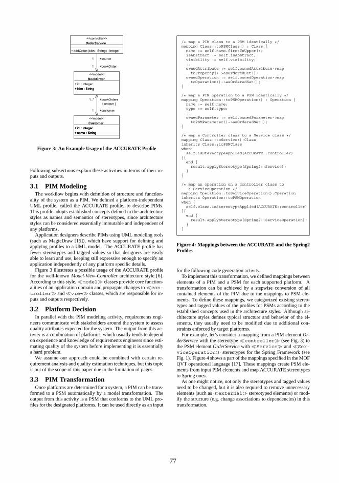
Figure 3: An Example Usage of the ACCURATE Profile
Following subsections explain these activities in terms of their in-puts and outputs.
3.1 PIM ModelingThe workflow begins with definition of structure and function-
ality of the system as a PIM. We defined a platform-independentUML profile, called the ACCURATE profile, to describe PIMs.This profile adopts established concepts defined in the architecturestyles as names and semantics of stereotypes, since architecturestyles can be considered essentially immutable and independent ofany platforms.
Application designers describe PIMs using UML modeling tools(such as MagicDraw [15]), which have support for defining andapplying profiles to a UML model. The ACCURATE profile hasfewer stereotypes and tagged values so that designers are easilyable to learn and use, keeping still expressive enough to specify anapplication independently of any platform specific details.
Figure 3 illustrates a possible usage of the ACCURATE profilefor the well-knownModel-View-Controllerarchitecture style [6].According to this style,≪model≫ classes provide core function-alities of an application domain and propagate changes to≪con-troller≫ and≪view≫ classes, which are responsible for in-puts and outputs respectively.
3.2 Platform DecisionIn parallel with the PIM modeling activity, requirements engi-
neers communicate with stakeholders around the system to assessquality attributes expected for the system. The output from this ac-tivity is a combination of platforms, which usually tends to dependon experience and knowledge of requirements engineers since esti-mating quality of the system before implementing it is essentiallya hard problem.
We assume our approach could be combined with certain re-quirement analysis and quality estimation techniques, but this topicis out of the scope of this paper due to the limitation of pages.
3.3 PIM TransformationOnce platforms are determined for a system, a PIM can be trans-
formed to a PSM automatically by a model transformation. Theoutput from this activity is a PSM that conforms to the UML pro-files for the designated platforms. It can be used directly as an input
/* map a PIM class to a PSM identically */mapping Class::toPSMClass() : Class {
name := self.name.firstToUpper();isAbstract := self.isAbstract;visibility := self.visibility;...ownedAttribute := self.ownedAttribute->map
toProperty()->asOrderedSet();ownedOperation := self.ownedOperation->map
toOperation()->asOrderedSet();}
/* map a PIM operation to a PSM identically */mapping Operation::toPSMOperation() : Operation {
name := self.name;type := self.type;...ownedParameter := self.ownedParameter->map
toPSMParameter()->asOrderedSet();}
/* map a Controller class to a Service class */mapping Class::toService():Classinherits Class::toPSMClasswhen{
self.isStereotypeApplied(ACCURATE::controller)}{
end {result.applyStereotype(Spring2::Service);
}}
/* map an operation on a controller class toa ServiceOperation */
mapping Operation::toServiceOperation():Operationinherits Operation::toPSMOperationwhen {
self.class.isStereotypeApplied(ACCURATE::controller)}{
end {result.applyStereotype(Spring2::ServiceOperation);
}}
Figure 4: Mappings between the ACCURATE and the Spring2Profiles
for the following code generation activity.To implement this transformation, we defined mappings between
elements of a PIM and a PSM for each supported platform. Atransformation can be achieved by a stepwise conversion of allcontained elements of the PIM due to the mappings to PSM ele-ments. To define these mappings, we categorized existing stereo-types and tagged values of the profiles for PSMs according to theestablished concepts used in the architecture styles. Although ar-chitecture styles defines typical structure and behavior of the el-ements, they usually need to be modified due to additional con-straints enforced by target platforms.
For example, let’s consider a mapping from a PIM elementOr-derServicewith the stereotype≪controller≫ (see Fig. 3) tothe PSM elementOrderServicewith ≪Service≫ and≪Ser-viceOperation≫ stereotypes for the Spring Framework (seeFig. 1). Figure 4 shows a part of the mappings specified in the MOFQVT operational language [17]. These mappings create PSM ele-ments from input PIM elements and map ACCURATE stereotypesto Spring ones.
As one might notice, not only the stereotypes and tagged valuesneed to be changed, but it is also required to remove unnecessaryelements (such as≪external≫ stereotyped elements) or mod-ify the structure (e.g. change associations to dependencies) in thistransformation.
77 77
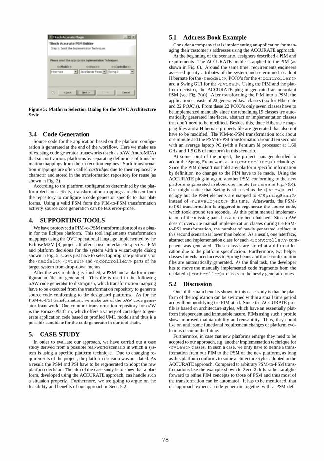
Figure 5: Platform Selection Dialog for the MVC ArchitectureStyle
3.4 Code GenerationSource code for the application based on the platform configu-
ration is generated at the end of the workflow. Here we make useof existing code generator frameworks (such as oAW, AndroMDA)that support various platforms by separating definitions of transfor-mation mappings from their execution engines. Such transforma-tion mappings are often calledcartridgesdue to their replaceablecharacter and stored in the transformation repository for reuse (asshown in Fig. 2).
According to the platform configuration determined by the plat-form decision activity, transformation mappings are chosen fromthe repository to configure a code generator specific to that plat-forms. Using a valid PSM from the PIM-to-PSM transformationactivity, source code generation can be less error-prone.
4. SUPPORTING TOOLSWe have prototyped a PIM-to-PSM transformation tool as a plug-
in for the Eclipse platform. This tool implements transformationmappings using the QVT operational language implemented by theEclipse M2M [8] project. It offers a user interface to specify a PIMand platform decisions for the system with a wizard-style dialogshown in Fig. 5. Users just have to select appropriate platforms forthe≪model≫, ≪view≫ and≪controller≫ parts of thetarget system from drop-down menus.
After the wizard dialog is finished, a PSM and a platform con-figuration file are generated. This file is used in the followingoAW code generator to distinguish, which transformation mappinghave to be executed from the transformation repository to generatesource code conforming to the designated platforms. As for thePSM-to-PSI transformation, we make use of the oAW code gener-ator framework. One common transformation repository for oAWis the Fornax-Platform, which offers a variety of cartridges to gen-erate application code based on profiled UML models and thus is apossible candidate for the code generator in our tool chain.
5. CASE STUDYIn order to evaluate our approach, we have carried out a case
study derived from a possible real-world scenario in which a sys-tem is using a specific platform technique. Due to changing re-quirements of the project, the platform decision was out-dated. Asa result, the PSM and PSI have to be regenerated to adopt the newplatform decision. The aim of the case study is to show that a plat-form, developed using the ACCURATE approach, can handle sucha situation properly. Furthermore, we are going to argue on thefeasibility and benefits of our approach in Sect. 5.2.
5.1 Address Book ExampleConsider a company that is implementing an application for man-
aging their customer’s addresses using the ACCURATE approach.At the beginning of the scenario, designers described a PIM and
requirements. The ACCURATE profile is applied to the PIM (asshown in Fig. 6). Around the same time, requirements engineersassessed quality attributes of the system and determined to adoptHibernate for the≪model≫, POJO’s for the≪controller≫and a Swing GUI for the≪view≫. Using the PIM and the plat-form decision, the ACCURATE plug-in generated an accordantPSM (see Fig. 7(a)). After transforming the PIM into a PSM, theapplication consists of 28 generated Java classes (six for Hibernateand 22 POJO’s). From these 22 POJO’s only seven classes have tobe implemented manually since the remaining 15 classes are auto-matically generated interfaces, abstract or implementation classesthat don’t need to be modified. Besides this, three Hibernate map-ping files and a Hibernate property file are generated that also nothave to be modified. The PIM-to-PSM transformation took aboutone minute and the PSM-to-PSI transformation around ten secondswith an average laptop PC (with a Pentium M processor at 1.60GHz and 1.5 GB of memory) in this scenario.
At some point of the project, the project manager decided toadopt the Spring Framework as a≪controller≫ technology.Since the PIM doesn’t not hold any platform specific informationby definition, no changes to the PIM have to be made. Using theACCURATE plug-in again, another PSM conforming to the newplatform is generated in about one minute (as shown in Fig. 7(b)).One might notice that Swing is still used as the≪view≫ tech-nology but the PSM elements are mapped to≪SpringBean≫instead of≪JavaObject≫ this time. Afterwards, the PSM-to-PSI transformation is triggered to regenerate the source code,which took around ten seconds. At this point manual implemen-tation of the missing parts has already been finished. Since oAWdoesn’t overwrite manual implementation classes during the PSM-to-PSI transformation, the number of newly generated artifact inthis second scenario is lower than before. As a result, one interface,abstract and implementation class for each≪controller≫ com-ponent was generated. These classes are stored at a different lo-cation due to the platform specification. Furthermore, two helperclasses for enhanced access to Spring beans and three configurationfiles are automatically generated. As the final task, the developerhas to move the manually implemented code fragments from theoutdated≪controller≫ classes to the newly generated ones.
5.2 DiscussionOne of the main benefits shown in this case study is that the plat-
form of the application can be switched within a small time periodand without modifying the PIM at all. Since the ACCURATE pro-file is based on architecture styles, which have an essentially plat-form independent and immutable nature, PIMs using such a profileshow improved maintainability and reusability. Thus, they couldlive on until some functional requirement changes or platform evo-lutions occur in the future.
Furthermore, in case that new platforms emerge they need to beadopted to our approach, e.g. another implementation technique for≪view≫ classes. In such a case, we only have to define a trans-formation from our PIM to the PSM of the new platform, as longas this platform conforms to some architecture styles adopted in theACCURATE approach. Compared to arbitrary PSM-to-PSM trans-formations like the example shown in Sect. 2, it is rather straight-forward to refine PIM concepts to those of PSM and thus most ofthe transformation can be automated. It has to be mentioned, thatour approach expect a code generator together with a PSM defi-
78 78

+doNew() : void+doOpen() : void+doSave() : void+doSaveAs() : void
<<controller>>
AddressBookController
+firstName : String+lastName : String+address : String+city : String+state : String+zip : String+phone : String
<<model>>
Entry
<<view>>
AddressBookView
+uri : String
<<model>>
AddressBook
+doEdit() : void+doDelete() : void+doAdd() : void
<<controller>>
EntryController
<<view>>
EditEntryView
<<view>>
AddEntryView
<<external>>
User
R8
-entries
0..*
-book
R3
-addview
-userR1
-view
-user
R11 -model
-editview
R13
-addview
-model
R10
-addview-controller
R9
-controller-editview
R6-controller
-model
R5
-controller-view
R4
-view
-model
R2-editview
-user
R12-controller
-model
Figure 6: A PIM for the Address Book Example
+firstName : String+lastName : String+address : String+city : String+state : String+zip : String+phone : String<<Key>>+key : long
<<Entity>>
Entry
+doNew() : void+doOpen() : void+doSave() : void+doSaveAs() : void
<<JavaObject>>
AddressBookController
<<JavaObject>>
AddressBookView
+uri : String<<Key>>+key : long
<<Entity>>
AddressBook
+doAdd() : void+doDelete() : void+doEdit() : void
<<JavaObject>>
EntryController
<<JavaObject>>
AddEntryView
<<JavaObject>>
EditEntryView
R8 -entries
0..*
-book
R6 -controller-model
R11 -model
-editview
R13
-addview
-model
R10
-addview-controller
R9
-controller-editview
R4
-view
-model
R5
-controller-view
R12-controller
-model
(a) POJO as a≪controller≫
<<ServiceOperation>>+doNew() : void<<ServiceOperation>>+doOpen() : void<<ServiceOperation>>+doSave() : void<<ServiceOperation>>+doSaveAs() : void
<<Service>>
AddressBookController
<<ServiceOperation>>+doAdd() : void<<ServiceOperation>>+doDelete() : void<<ServiceOperation>>+doEdit() : void
<<Service>>
EntryController
+firstName : String+lastName : String+address : String+city : String+state : String+zip : String+phone : String<<Key>>+key : long
<<Entity>>
Entry
<<SpringBean>>
AddressBookView
+uri : String<<Key>>+key : long
<<Entity>>
AddressBook
<<SpringBean>>
EditEntryView
<<SpringBean>>
AddEntryView
R8 -entries
0..*
-book
(b) Spring as a≪controller≫
Figure 7: Two PSMs using Hibernate as a≪model≫ and Swing GUI as a≪view≫
nition. Otherwise, we would have to implement the PSM-to-PSItransformation by ourselves.
Another advantage worth mentioning is that handwritten parts ofsource code are preserved during code regeneration. In the casestudy, Swing GUI and Hibernate classes are reused, except thattheir instantiation code (i.e. constructor calls) is replaced by a XMLconfiguration file for Spring. On the other hand, the generated partfor ≪controller≫ classes are regenerated based on the Springservice components, while handwritten part of the POJO’s are leftuntouched. This means that there are some remaining parts, whichhave to be migrated manually, even though task can be achieved ina reasonable time due to the size of the handwritten code. We sup-
pose, that generating complete source code from PIM or providinghelp and guidance for each possible migration are two possible so-lutions to address these problems.
6. RELATED WORKThere is already some existing work focusing on platform inde-
pendent modeling and model transformation in a different problemdomain. Bezivin et al. [4] propose to use ATL transformation [7] totransform PIMs defined by Enterprise Distributed Object Comput-ing into PSMs for different web service platforms. Billig et al. [5]define PIM-to-PSM transformations in the context of EJB by usingQVT [17]. Besides this, some related work define PIMs via UML
79 79
profiles. Link et al. propose to use GUIProfile to model PIMs andtransform them into PSMs [13]. Richly et al. focus on a UML pro-file to define PIMs for databases [11]. He et al. use template rolemodels together with PIM profiles for templates to design PIMs,which are specific for web applications [12] . Ayed et al. propose aUML profile for modeling platform independent context-aware ap-plications [2]. Lopez-Sanz et al. define a UML profile for service-oriented architectures [14]. Finally Fink et al. combine UML andMOF profiles for access control specifications [9]. As one can no-tice, there are a lot of approaches, which describe a PIM on a moreabstract level than a PSM. Even so, these approaches are still tai-lored to a specific technology or architecture and thus need somedetailed knowledge of the concrete problem domain. Furthermore,the adoption to a different problem domain or architecture such asMVC is hindered due to the specific notations of these PIMs.
7. CONCLUSION AND FUTURE WORKIn this paper, we have stated out some clear problems of MDD
approach when it has to change a platform to another. To addressthis problem, we have introduced an approach called ACCURATE,which consists of a profile for describing PIMs and transformationmappings to bridge a PIM to PSMs of existing code generators. Ourapproach shows how to specify systems easily without any PSMmodeling skills. The approach offers much automation of the de-velopment process and thus reducing costs under the pressure of ashorter time-to-market.
Furthermore, a prototype tool is provided, which both assures theintegrity during model transformation and offers guidance throughthe software development process to the user. The current imple-mentation of the tool provides a workable and extendable solutionto address the stated problems. However, there are still some en-hancements that we would like to adopt to our approach in the nearfuture. These possible extensions can be summarized as follows:
1. Further evaluation: This paper focused on applying theACCURATE approach to the MVC architecture style. Sincethis is just one possible example for an architecture, we wouldlike to evaluate our approach to a different architecture style(e.g. Pipes and Filters or Blackboard) and on a larger scale toprove the applicability more sustained.
2. Platform decision models: As mentioned before, the plat-form decision can be supported by assessing quality attributesexpected for the system. We are going to introduce platformdecision models more precisely. The first model we are nowfocusing on is based on Bayesian networks, which allows toinfer platform decisions based on predefined probability dis-tribution metrics.
3. Interaction with coding: In theory, complete source codecould be generated from a model. But due to unfamiliarity ofgraphical PIM modeling and immaturity of tool support forMDD at this moment, developers prefer to finish up imple-mentation by complementing or adjusting generated sourcecode in their common programming languages like Java. Wewould like to adopt oAW recipes to help the developer trackthe missing parts of the implementation, and hopefully prop-agate changes in source code (e.g. adding a method) to itsoriginated PIM.
8. REFERENCES[1] AndroMDA.org. AndroMDA.org - Home.
http://www.andromda.org/.
[2] D. Ayed and Y. Berbers. UML Profile for the Design of aPlatform-Independent Context-Aware Applications. InMODDM’06: Proceedings of the 1st Workshop on ModelDriven Development for Middleware, pages 1–5, 2006.
[3] J. Bezivin and S. Gerard. A Preliminary Identification ofMDA Components. InGTCMDA’02: Proceedings of theOOPSLA 2002 Workshop in Generative Techniques in theContext of Model Driven Architecture, 2002.
[4] J. Bezivin, S. Hammoudi, D. Lopes, and F. Jouault. ApplyingMDA approach for Web service platform. InEDOC’04:Proceedings of the 8th IEEE International EnterpriseDistributed Object Computing Conference, pages 58–70,2004.
[5] A. Billig, S. Busse, A. Leicher, and J. G. Süss. PlatformIndependent Model Transformation Based on TRIPLE. InMiddleware’04: Proceedings of the 5th ACM/IFIP/USENIXInternational Conference on Middleware, pages 493–511,2004.
[6] F. Buschmann, R. Meunier, H. Rohnert, P. Sommerlad, andM. Stal.Pattern-Oriented Software Architecture: A System ofPatterns. John Wiley & Sons, Inc., 1996.
[7] eclipse.org. ATLAS Transformation Language (ATL).http://www.eclipse.org/m2m/atl/.
[8] eclipse.org. Model to Model (M2M) Project.http://www.eclipse.org/m2m/.
[9] T. Fink, M. Koch, and K. Pauls. An MDA approach toAccess Control Specifications Using MOF and UMLProfiles.Electronic Notes in Theoretical Computer Science,142:161–179, 2006.
[10] fornax-platform.org. The Fornax-Platform.http://www.fornax-platform.org/.
[11] D. Habich, S. Richly, and W. Lehner. GignoMDA:Exploiting Cross-layer Optimization for Complex DatabaseApplications. InVLDB’06: Proceedings of the 32ndInternational Conference on Very Large Data Bases, pages1251–1254, 2006.
[12] C. He, F. He, K. He, and W. Tu. Constructing PlatformIndependent Models of Web Application. InSOSE’05:Proceedings of the 2005 IEEE International Workshop onService-Oriented System Engineering, pages 85–92, 2005.
[13] S. Link, T. Schuster, P. Hoyer, and S. Abeck. FocusingGraphical User Interfaces in Model-Driven SoftwareDevelopment. InACHI’08: Proceedings of the 1stInternational Conference on Advances in Computer-HumanInteraction, pages 3–8, 2008.
[14] M. López-Sanz, C. Acuña, C. Cuesta, and E. Marcos. UMLProfile for the Platform Independent Modelling ofService-Oriented Architectures.Software Architecture, pages304–307, 2007.
[15] No Magic. MagicDraw UML.http://www.magicdraw.com/.
[16] OMG. MDA Guide Version 1.0.1.http://www.omg.org/docs/omg/03-06-01.pdf,2003.
[17] OMG. Meta Object Facility (MOF) 2.0Query/View/Transformation Specification Version 1.0.http://www.omg.org/docs/formal/08-04-03.pdf,2008.
[18] openArchitectureWare.org. Official openArchitectureWareHomepage.http://www.openarchitectureware.org/.
80 80

Evolution of a Domain Specific Language and itsengineering environment - Lehman’s laws revisited
Mika KarailaMetso Automation Inc.
Lentokentänkatu 1133101 Tampere, FINLAND
+358407612563
ABSTRACTAutomation domain is under continuous change with newrequirements. Metso Automation has been one of the first vendorsof digital automation systems (1978 Damatic). The last 20 yearsof development and maintenance of system architecture and adynamic, flexible engineering environment has enabled us tosuccessfully live with the changes. In this paper, evolution of adomain specific visual system configuration language calledFunction Block Language (FBL) and a supporting environment isdiscussed. The evolution is reflected to Lehman's laws. MetsoAutomation’s solutions for surviving with the implications of thelaws are also discussed.
Categories and Subject DescriptorsD.3.2 [Language Classifications]: Specialized applicationlanguages – domain specific language, visual language.
General TermsDesign, Reliability, Experimentation, Languages.
KeywordsVisual Domain Specific Language, Evolution, Software Laws,Software Patterns.
1. INTRODUCTIONA distributed control system (DCS) refers to a control systemusually of a manufacturing system, process or any kind ofdynamic system, in which the controller elements are not centralin location but are distributed throughout the system with eachcomponent sub-system controlled by one or more controllers. Theentire system of controllers is connected by networks forcommunication and monitoring.For building DCSs at Metso Automation, a multi-levelarchitecture is used in MetsoDNA DCS. Controllers use hardwareunits such as input/output cards (I/O) to connect field devices intoa system. Software is located in controllers, I/O cards and fielddevices. There are different kinds of firmware programs, busprotocol stacks, operating systems and different kinds of tools anddatabases. An automation system executes programs in real-timein a distributed environment. It can control a small process justsome devices or a huge factory with several paper machines, stockpreparation and own power plant. One key element iscommunication between the units. Communication must bedeterministic, real-time, robust and scalable.Function Block Language (FBL), developed at MetsoAutomation, is a visual programming language for writing real-
time control programs for distributed environments. FBLprograms are represented as diagrams that will implementapplication programs. Each diagram typically contains 5-10smaller application programs, which are loaded into a distributedsystem. A typical paper manufacturing plant automation is builtfrom 5000 to 10000 FBL programs. They control 15000input/output connections (I/O). Total amount of small applicationprograms is over 100000.FBL is part of a bigger product family that has a long life cycle.We will show how in automation domain both FBL andsupporting programming environments such as FBL editor andother tools will need effort for their controlled and successfulmaintenance.Section 2 introduces FBL and its history in brief. Section 3 brieflyintroduces Lehman's laws of software evolution [12]. Theycharacterize the ways large software systems tend to evolve. Ineach subsection, Lehman's laws are discussed with respect to theautomation domain, FBL and its programming environment. Thissection also explains the methods that we use to survive with theevolution. It will explain Metso Automation’s maintenanceprocess and its benefits. The process has been developed tomanage the challenges software evolving according to Lehman'slaws creates. The key idea is to manage the main principles likeworking methods and product features and keep the system anddomain specific language in balance during evolution. Section 4will discuss and summarize items introduced
2. Domain Specific LanguagesThe term domain-specific language (DSL) [2] has become popularin recent years in software development to indicate aprogramming language or specification language dedicated to aparticular problem domain, a particular problem representationtechnique, and/or a particular solution technique [11]. The conceptis not new. Special-purpose programming languages and all kindsof modeling/specification languages have existed, but the term hasbecome more popular due to the rise of domain-specific modeling(DSM) [10]. Domain-specific languages are 4GL programminglanguages. Examples include spreadsheet formulas and macros,YACC [5] grammars for creating parsers, regular expressions,Generic Eclipse Modeling System [21] for creating diagramminglanguages, advanced DSM tool MetaEdit+ [18], Csound [19], alanguage used to create audio files, and the input language ofGraphViz [3], a software package used for graph layout. Theopposite of a domain-specific language is a general-purposeprogramming language, such as C or Java, or a general-purposemodeling language such as UML.
8181
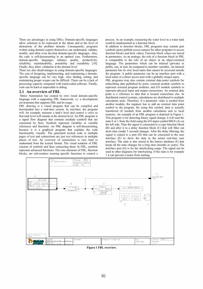
There are advantages in using DSLs. Domain-specific languagesallow solutions to be expressed in the idiom and at the level ofabstraction of the problem domain. Consequently, programswritten using domain experts themselves can understand, validate,modify, and often even develop domain-specific languages. Also,the code is self-documenting in an optimal case. Furthermore,domain-specific languages enhance quality, productivity,reliability, maintainability, portability and reusability [10].Finally, they allow validation at the domain level.There are also disadvantages in using domain-specific languages.The cost of designing, implementing, and maintaining a domain-specific language can be very high. Also finding, setting, andmaintaining proper scopes can be difficult. There can be a lack ofprocessing capacity compared with hand-coded software. Finally,code can be hard or impossible to debug.2.1 An overview of FBL Metso Automation has created its own visual domain-specificlanguage with a supporting FBL framework, i.e. a developmentenvironment that supports FBL and its usage.FBL drawing is a visual program that can be compiled anddownloaded into a real-time system. In real-time, the programwill, for example, measure a tank's level and control a valve sothat tank level will remain at the desired level. An FBL program isa signal flow diagram that contains multiple symbols that areconnected by lines. Symbols represent variables or variablereferences and functions. An FBL diagram is self-documenting,because it is a graphical program that explains the codefunctionality visually. The generated textual code is multiplepages of text and connections are just text references in multipleplaces of text. An overview of connections is very hard tounderstand from the textual format. The visual notation of FBLconsists of symbols and lines connecting them. In FBL, symbolsrepresent advanced functions. The core elements of FBL, functionblocks, are sub-routines running specific functions to control a
process. As an example, measuring the water level in a water tankcould be implemented as a function block.In addition to function blocks, FBL programs may contain portsymbols (ports publish access names) for other programs to accessfunction blocks and their values. Function block values are storedin parameters. As an analogy, the role of a function block in FBLis comparable to the role of an object in an object-orientedlanguage. The parameters which can be internal (private) orpublic, can, in turn, be compared to member variables. An internalparameter has its own local name that cannot be accessed outsidethe program. A public parameter can be an interface port with alocal name or a direct access port with a globally unique name.FBL programs may also contain external data point symbols forsubscribing data published by ports, external module symbols torepresent external program modules, and I/O module symbols torepresent physical input and output connections. An external datapoint is a reference to data that is located somewhere else. Indistributed control systems, calculations are distributed to multiplecalculation units. Therefore, if a parameter value is needed fromanother module, the engineer has to add an external data pointsymbol to the program. By using this symbol, data is actuallytransferred (if needed) from another calculation unit to localmemory. An example of an FBL program is depicted in Figure 1.This program is for detecting binary signal change; it will read thestate 0 or 1 from the field using the I/O-input symbol BIU8 (A) onthe left side. Then the signal is connected to a copy function block(B) and after it to a delay function block (C) that will filter outshort time (under 5 second) changes. After the delay filtering, thesignal is copied to a port (D) that can be connected to the userinterface (E) to show the state in the actual real-time userinterface. The state is also stored in the history database (F) thatkeeps all the state changes for a long time (months or years). Theinterface port (G) is for the interlocking usage. The signal can beused in other diagrams for interlocking. If the state is for example1 it can prevent a motor from starting.
Figure 1 FBL overview.
8282

2.2 Development history of FBLIn 1988, the first release of FBL was introduced to customers. Itincluded all the basic elements: ports, externals, function blocksand I/O modules of the language itself. The code generator washand written and the implementation contained a pattern basedtext generator [9] that used output templates. Currently, there areframework tools available for that purpose [17].The Automation Language is a simple domain specific textuallanguage. The FBL code generator produces AutomationLanguage. FBL has been used from the year 1988. The FBLprogramming IDE, editor is FbCAD (product name for theFunction Block CAD). The Function Test tool was introduced in1990. It allows the user to debug run-time values in the FbCAD(visual debugging mode). This is not always trivial with DSLbecause generated code may need its own IDE that can be hard toimplement. Function Explorer is a tool for multiple users in aclient-server environment. It allows concurrent programming andis an easy way to change parameters for the FBL programs savedin the database. The last major development step was support for"Templates" in the year 2003. Visual templates are domainspecific models that can be used to create new FBL programinstances efficiently [8]. Another way to support reuse relies onpatterns. In the last years, we have detected patterns from visualprograms. They are solutions to small problems that can be solvedwith few symbols.The development of FBL has had various goals. One of them is toaim at a visual language to make programs understandable and theprogramming environment easy to use and learn. The user canalways add both textual and graphical comments to the program.The initial setup for developing FBL was the fact that theautomation language was too hard to understand and theconnection network was impossible to figure from the textualcode. The basic architecture separates user interface to its ownpart and the code generator to its own. In the beginning, the basicuser interface was static and very simple. It was then extended,and more dynamics were added, like the visual testing tool. Nowthe focus of user interface development is on usability issues.Also a lot of new dynamics have been added to fulfill newrequirements. Programming effectiveness is one major target. Wealways try to make programming faster. There are smallimprovements in the user interface level and in the language level,but the biggest improvement has been the introduction oftemplates [8]. Templates are reusable domain models that can beinstantiated. An instance will need only a set of parameters towork. It has significantly reduced engineering work and madelarge modifications easy to make. Adding new elements to it havealso extended the FBL language itself. Finally, improving thecode generation in FBL has raised the quality of the programs. Itis more accurate and detects more errors and also gives warningsto users.If we compare FBL programs created in 1988 and now, the majordifference is that they are now bigger and more complex. This isdue to the new requirements for higher automation levels.3. Lehman's laws and evolution of FBL andits supporting engineering environmentIn this section, Lehman's laws are revisited in the context of theautomation industry domain and in particular the evolution ofFBL and its programming environment. Each of eight laws isdiscussed and the name of the law is the title of the subsection.These results are collected and formed based on 20 years ofdevelopment history. The connections and network between
Metso Automation's own people and customers have given a lot offeedback on FBL and its programming environment. Themaintenance process of FBL itself is an iterative process thatrelies on the feedback system. These processes and methods canbe used to gain better results and to manage the evolution FBL.
3.1 Law I: Continuing change
E-type systems must be continually adapted else they becomeprogressively less satisfactory.
The automation domain itself is under change. In addition, alsothe environment that is used for FBL and its editor and other toolsare under change. For instance, the operating system has changedmultiple times from UNIX (Xenix, SCO, Ultrix, and HP) to DOSand Windows (NT, XP, Vista) and also the compiler is underchange all the time. The CAD platform that is the base of the FBLeditor has been changed according to the operating system andneeded compiler. The selected CAD platform (AutoCAD) was amarket leader. The use of a commercial platform helped a lot,because its development and maintenance was carried out byothers. The only major work was to port the FBL user interface(editor) always into the selected release. The selection processwas guided by a technology roadmap. This kind of preplanninggave development teams time to prepare for new things inadvance.This does not directly affect FBL itself, but the editor and thecode generator both require major maintenance work. There is acompatibility requirement; life-time cycles are demanding inautomation domain. FBL editor changes according to the style ofthe CAD platform and operating system. The change in the visualappearance is significant if we compare the very first 640 x 480resolution to the current 1024 x 768 one. Outlook is also improvedby new better fonts and more colors that are used today. ActualFBL improvements have been mostly visual.As Lehman's first law indicates, resisting changes is not a fruitfulsolution in the long run. Instead, we have chosen to live with thechanges and upgrade environment. The software environmentchanges in the domain create needs for changes in FBL and itstools: the domain specific language must evolve with theenvironment.
3.2 Law II: Increased complexity
As an E-type system evolves, its complexity increases unless workis done to maintain or reduce it.
Metso Automation DCS size grows both hardware & software.Also other additional functions make the system more complex.As an example, new I/O-cards are needed and they include newfeatures and more channels. FBL language supports changes, e.g.new symbols can be created into FBL. Some of these are typicallysimilar to existing ones, like new function blocks. New functionblocks do not extend FBL, but give new features forprogramming. This was seen already 20 years ago. The internalarchitecture of the code generator was built to be generic and thevariation point was built into symbol level.There are intelligent devices with new communication protocolsevolving which will require support. The Foundation Fieldbus(FF) [4] integration, for instance, needed its own FBL symbols.The code generation was extended to support FF configuration.This required new semantics. This was mainly solved by the
8383

generic part, only the connection solver needed a specialalgorithm and the 'output-printer' was extended for FF domainwith new C++ classes. Other integrated protocols are Profibus DP[16] and OLE [13] for Process Control (OPC) [15]. They,however, did not need such big integration work for FBL.In the FBL language level complexity is isolated to its ownsymbols. The code generator architecture does not need in atypical case any changes. The increased complexity is isolatedinto FBL editor and code generation as configurable extensions.In this way new protocol specific variations can be integrated bysettings and they will not need code changes into the FBL toolsevery time. A typical way to reduce complexity is abstraction andcapsulation, but in cases where this is not possible it is good tofirst identify variation points and then locate them to selectedplaces in architecture.3.3 Law III: Self regulation
E-type system evolution process is self regulating with distributionof product and process measures close to normal.
In the automation domain we cannot release a new build eachweek or month. Customers cannot shut down factories so often. Anormal case is to have one planned shutdown each year,sometimes perhaps only twice a year.In distributed automation system architecture allows that parts canbe turned off and on. In this way non-critical parts can beupdated/upgraded or even replaced while the process is running.Usually it is a broken device or I/O-card that must be replaced.Same modularity can be seen in FBL language level. An FBLprogram can be downloaded into the system in runtime withoutany disturbance. The modularity makes it possible to downloadsmall application programs into the running factory withoutinterruptions.The evolution process that requires new technologies worksaccording to Moore's law [14]. But in automation domain a newtechnology, for example a new operating system, is taken into useafter careful consideration and after other industry experiences.Technological steps are taken in 2-3 year intervals. As anexample, FBL editor and operating system are upgraded with thatinterval. A conservative attitude and caution normalizetechnological evolution.3.4 Law IV: Conservation of organizationalstability
The average effective global activity rate in an evolving E-typesystem is invariant over product lifetime.
In the automation domain you have to know something about fielddevices, process, and electronics. The automation systemarchitecture and teams are formed in the same way (logicalstructures are similar, c.f. Conway's law [1]). Development andproject organizations have been structured in the same way forabout the last 20 years. The team cannot change many persons atthe same time because the learning process takes time. Nobodycan have all the knowledge but a good programmer mustunderstand the domain. It usually takes months to start tounderstand the whole automation domain from the controller levelto the device level.A small core team is an example of good practice that allowssmooth FBL development and maintenance. A challenging
environment and continuous learning keep these people pleased.The needed domain knowledge that requires multi-talented peoplewill help in keeping organizational stability.3.5 Law V: Conservation of familiarity
As an E-type system evolves all associated with it, developers,sales personnel, users, for example, must maintain mastery of itscontent and behavior to achieve satisfactory evolution. Excessivegrowth diminishes that mastery. Hence the average incrementalgrowth remains invariant as the system evolves.
The principles, namely business rules in the domain, are very oldin distributed systems. As new communication protocols areintegrated into the system, they will have the following typicalcharacteristics like determinism and robustness. These kinds offacts always keep architectural solutions very stable. There arearchitectural level design patterns that give good solutions to theseproblems.The abstraction level in the FBL language is selected to hideunnecessary parts from the end user. The needed parameters areasked from the user and the semantics and the basic layout ofcommunication symbols have remained the same since 1989. Inthe FBL language the basic symbols are still almost identical.We have to keep all new extensions somehow similar to existingones. FBL symbol editor and FBL editor are integrated andmainly old symbols are handmade. The FBL editor has samelogical operations for all similar symbols. In this way, the learningprocess is easier and more logical for an engineer who will useFBL. As people are conservative and do not like very big changesit helps to keep things familiar.
3.6 Law VI: Continuing growth
The functional content of E-type systems must be continuallyincreased to maintain user satisfaction over their lifetime.
Automation systems are typically growing. The applicationprograms that we have delivered to factories are growing. In thehardware architecture the old hardware was VME based Motorola68030 processors with 2 Mb Memory. Now we use Intel basedPentium with 256 Mb Memory. Also the communication busspeeds have improved from 2 Mb/s to 100 Mb/s. In the hardwarelevel the growth is seen clearly.We have a reuse library that contains most of the deliveredprojects. We have measured from the library statistics that theaverage amount of function blocks in the FBL program hasincreased from 20 to 30 in the last 10 years (cf. Table 1).
Table 1 Project Function Blocks and Complexity growth.Project Average number of
Function BlocksComplexity
A 1999 15 8B 1999 27 3C 1999 15 5D 1999 7 2E 1999 28 9F 2008 34 19G 2008 25 10H 2008 30 12I 2008 28 15
8484

The project size has grown from 1000 to 5000 applicationprograms. This is partly due to the technology change. Fielddevices are more intelligent and they are connected by bus intothe system. Instead of having signals connected by traditionalwires there are multiple software signals coming from onephysical connection. But each software signal still needs its ownhandling, which causes growth. This all means that the totalamount of program code is five times more than 10 years earlier(1999 --> 2008).We can get these statistics of FBL usage easily because the sameworking methods are used in each customer project. One part ofthe customer project process is to archive it.The engineering tools are also growing. We can measure from theversion control system statistics that will show the FBL codegenerator & DB-adapter growth from 2000 to the current year.2008 has been about 10 kLOC, which is in average 1 kLOC/year(numbers shown in Table 2). The statistics show that FBL itselfhas grown during 2000-2008 with about 600 new function blocksand other symbols, the average being 75 new symbols per year.We have thus observed also growth in the FBL language itself,not only in its programming environment. The author of this paperis not aware that Lehman’s laws have been earlier discussed in thecontext of programming languages. They are, however, widelydiscussed in the context of large software systems. Continuousgrowth of FBL itself is interesting and due to its increasinglybroad use in different contexts and by different customers.Moreover, we assume that such growth is not typical for generalpurpose languages, but can be more natural for domain-specificones.
Table 2 Code generator and DB adapter size and growth.Program Code and Lines in
Year 2000Codes and Linesin Year 2008
CodeGenerator
35999 44304
DB adapter 20642 31986
These numbers show that increased functionality increases thecode in the application layer (not in the system core). In thesystem core, the increase comes from the supported hardware,operating systems and new communication protocols. We canmanage the growth because it is isolated into selected places. Thevariation points are designed and the solution is to use data centricgeneration (usually more symbols needed). The code generatorcore part is very stable. The initial number of symbols wasapprox. 500 and now it is over 1600 symbols. A goodarchitecture helps in managing the growth. The amount of code isnot growing, instead, the growth is at data level.A very long life-cycle and evolution has not yet affected to themeta-model. The original meta-model is still used. Thearchitecture separates extensions into symbols, and the codegenerator is still quite compact. The language rules and semanticsare fine-tuned by the code generator.3.7 Law VII: Declining quality
The quality of E-type systems will appear to be declining unlessthey are rigorously maintained and adapted to operationalenvironment changes.
The previous laws, like continuous change, increased complexityand continuing growth, are easily causing problems in quality
control. Also all new features, operating system/hardware changesand new protocols can cause new bugs.The basic architecture isolates modifications. It will also keep thesystem robust because a bug in one part will not crash the wholesystem. In the language level, FBL helps in regression testingbecause it can be used in different environments and differentversions. All old FBL programs should be compatible upwards.This kind of FBL interoperability helps in testing. The same FBLprogram can be used and code generator results can be used forcomparing and validating that the system is still working in thesame way. Interoperability and compatibility can be used inregression testing to help in quality assurance.
3.8 Law VIII: Feedback system
E-type evolution processes constitute multi-level, multi-loop,multi-agent feedback systems and must be treated as such toachieve significant improvement over any reasonable base.
New communication methods like the internet and email allowcustomers to contact vendors much easier. The informationcollecting process uses data from multiple sources. The feedbackprocess is shown in Figure 2. Wishes for new features and minorchanges come from the testing and support contacts. All thetesting defects are reported and stored in a database. This databaseis actually a huge diary that contains events that are caused byprogrammers or designers. The support contacts from thecustomers or own personnel are also stored in the database. Thesetools are now integrated so that the user can link and create cardsjust by one click. So for the development and maintenance all thedefects are collected into one database. In this way, it is mucheasier to prioritize errors and decide who should fix and test theerror and when. Information processing is now easier and projectmanagers can focus on those errors in priority order. This makesthe focus setting easier and the error handling is up to date all thetime.The process is now organized and made formal. It allows us tohave the feedback system running 24/7 and also check that eachcase is handled. We archive and analyze all the feedback so that ithelps us to improve the quality of the products. The amount offeedback issues have grown from some hundreds to over threethousand during the last 20 years. The actual reason comes fromthe fact that earlier issues were handled more freely. Formalizedfeedback entering was started at the end of the year 2004. Thismade it more visible and easier to statistically handle all issues. Innumbers this means: bug reports over 1300/year, support cases1800/year, dissatisfactions over 100/year and ideas 200/year.These issues concern engineering, user interface, controls andhardware parts. Most of the issues are not critical, but they arefocusing mostly on user interface and usability issues today. Weformalize, control and analyze all collected feedback to reallyimprove both product quality and product features.The whole feedback framework is made to help, link and reuseinformation more easily. Also tracking and testing is managedthrough the process. The process is more transparent and trackingfrom initiator, coder, and tester to final version report is possible.Each bug report or feature request has its own number and thosecan be selected to a version report. This makes the quality of theprocess better. Different views into bug records make it possibleto filter and find not handled records. One way to first categorizea bug is to use architecture. The component level can be used to
8585
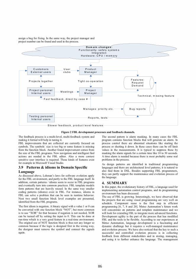
assign a bug for fixing. In the same way, the project manager andproject number can be found and used in the process.
P ro je c tM a n a g e r
P ro d u c tM a n a g e r
C u s to m e rsE x te rn a l u s e rs
P ro je c t p e rs o n e lIn te rn a l u s e rs
T ig h t c o -o p e ra t io n
U s e rc lu b s
M e e t in g s
P ro je c ts to g e th e r F e a tu re s :R e q u e s tD e m a n d
D o m a in c h a n g e s :F u n c tio n a l ity : s a fe ty s y s te m s
In te g ra tio nH a rd w a re : C P U / m e m o ry
B u g re p o r ts
T e s tin g p e rs o n e lIn te rn a l u s e rs
M a n a g e s : p r io r ity e tc .
R e p o r ts , te s ts
T e c h n ic a l , m is s in g fe a tu reF a s t fe e d b a c k , d i re c t b y c a s e #
S lo w e r fe e d b a c k , p ro d u c t le v e l fe a tu re s
Figure 2 FBL development processes and feedback channels.The feedback process is a multi-level, multi-feedback system andmaking it formal will help in tuning it.FBL improvements that are collected are currently focused onsymbols. The symbols´ size is too big or some feature is missingfrom the function block. Another found improvement comes fromthe size of the FBL programs. New navigation and intelligent findactions are needed in the FBL editor. Also a more contextsensitive user interface is required. These kinds of features existfor example in Microsoft Visual Studio.
3.9 Patterns & idioms in Domain SpecificLanguageAs discussed above, Lehman’s laws for software evolution applyfor the FBL environment, and partly to the FBL language itself. Inaddition, certain patterns / idioms seem to occur in FBL programsand eventually turn into common practices. FBL template modelsform patterns that are heavily reused. In the same way smallercoding patterns (idioms) exist in FBL. For instance, idioms inFBL can solve a problem that can be seen in runtime behavior.Next two small function block level examples are presented,identified from the FBL programs.The first idiom is negation. A binary signal with a value 1 or 0 canbe converted with one function block “NOT”, but more commonis to use “XOR” for that because if negation is not needed, XORcan be turned off by setting the input to 0. This can be done atrun-time which is a very good feature in a real-time environment.The original use of NOT function block is thus not any longer socommon because if the logic is designed first in the wrong way,the designer must remove the symbol and connect the signalsagain.
The second pattern is alarm masking. In many cases the FBLprogram contains function blocks that will generate an alarm. Inprocess control there are abnormal situations like starting theprocess or shutting it down. In these cases there can be off limitvalues in the measurements. It is typical to suppress these bymasking the alarm signals for a certain time like 10 to 30 seconds.A time alarm is needed because there is most probably some realproblems in the process.As design patterns are identified in traditional programminglanguages and there are architectural level patterns, it is natural toalso find them in DSL. Besides supporting FBL programmers,they can partly support the maintenance and evolution process ofthe language.
4. SUMMARYIn this paper, the evolutionary history of FBL, a language used forimplementing automation control programs, and its programmingenvironment has been discussed.The use of FBL is growing. Interestingly, we have observed thatthe projects that are using visual programming are very well onschedule. Component reuse is the first step in efficientprogramming [6, 7, 8 and 20]. Metso Automation’s future workwill concentrate on patterns and template maintenance and wewill look for extending FBL to integrate more advanced functions.Development agility is the part of the process that has modifiedFBL and the tools to be flexible. According to our experiences atMetso Automation, language development is a fascinating anddynamic challenge but it requires a well-managed maintenanceand evolution process. We have also noticed that the key to such asuccessful and controlled evolution process is in collectingfeedback from different stakeholders and in storing, managing,and using it to further enhance the language. The management
8686

must have a very large product view and good knowledge aboutused techniques.These experiences are limited to the automation industry and inparticular to FBL and our experiences at Metso Automation.Therefore, we do not claim all the results can be directlygeneralize to e.g. general purpose programming languages.However, we feel that the process improvement and methods tolive with Lehman’s laws can be adapted to other cases andsoftware maintenance. In a dynamic environment, it is veryimportant to manage the maintenance and evolution processes.One success factor has been that we control the maintenance andevolution process with iteration. An essential factor for thesuccess has been a feedback handling mechanism that gives uspriorities and new ideas for further development. Another successfactor is architecture that is still dynamic and flexible.The management of development and maintenance processes helpin evolution. Both processes have gone through improvementsand generations.
ACKNOWLEDGMENTSThe author would like to thank Tarja Systä for her comments andsupport in writing. This article was written at Tampere Universityof Technology.
5. REFERENCES[1] Conway, M.E. 1968 How do Committee's Invent,
Datamation, 14 (5): 28-31.[2] Deursen, A. , Klint, P. and Visser, J. 2000 Domain-
Specific Languages: An Annotated Bibliography, ACMSIGPLAN.
[3] Ellson, J. and Gansner, E. and Koutsofios, E. and North,S.C. and Woodhull, G. 2002, Graphviz— Open SourceGraph Drawing Tools Springer Berlin / Heidelberg,Volume 2265/2002, 594-597.
[4] Foundation Fieldbus http://www.fieldbus.org/[5] Johnson, S. C. 1975 Yacc: Yet Another Compiler-
Compiler. Compiler, Computing Science Technical ReportNo. 32, , Bell Laboratories, Murray Hill, NJ 07974
[6] Karaila, M. and Leppäniemi, A.2004 Multi-Agent BasedFramework for Large Scale Visual Program Reuse, IFIP,Volume 159/2005, 91-98.
[7] Karaila M., Systä T. 2005 On the Role of Metadata inVisual Language Reuse and Reverse Engineering – AnIndustrial Case Electronic Notes in Theoretical ComputerScience, 2005, Volume 137, Issue 3, 29-41.
[8] Karaila, M. and Systä, T. 2007 Applying Template Meta-Programming Techniques for a Domain-Specific VisualLanguage--An Industrial Experience Report, ICSE 2007.
[9] Kastens, U. PTG: Pattern-based Text Generator. v1.1[10] Kelly, S. and Tolvanen, J-P.2008 Domain-Specific
Modeling Wiley-IEEE Computer Society Press, 448.[11] Korhonen, K. 2002 A case study on reusability of a DSL in
a dynamic domain, 2nd OOPSLA Workshop on DomainSpecific Visual Languages.
[12] Lehman, M.M. ,Ramil, J F. ,Wernick, P D. ,Perry, D E.and Turski, W M. 1997 Metrics and laws of softwareevolution -The Nineties View Software, Proc. of the 4thInternational Symposium on Software Metrics.
[13] Microsoft OLE. http://support.microsoft.com/kb/86008[14] Moore, G. 1965 Moore's law.[15] OPC communication http://www.opcfoundation.org/[16] Profibus http://www.profibus.com/[17] Schmidt, C. and Kastens, U. and Cramer, B. Using DEViL
for Implementation of Domain-Specific Visual Languages.University of Paderborn.
[18] Tolvanen, J-P and Pohjonen, R. and Kelly, S. 2007Advanced Tooling for Domain-Specific Modeling:MetaEdit+., Computer Science and Information SystemReports, Technical Reports, TR-38, University ofJyväskylä, Finland 2007, ISBN 978-951-39-2915-2.
[19] Vercoe, B. 1992 A Manual for the Audio ProcessingSystem and Supporting Programs with Tutorials.
[20] Vyatkin, V. and Hanish, H-M. 2005 Reuse of Componentsin Formal Modeling and Verification of DistributedControl Systems ETFA 2005. 10th IEEE Conference onPublication Date: 19-22 Sept. 2005 Volume: 1 On page(s):129 - 134, 2005, Volume 1, 129-13.
[21] White, J. and Douglas C. Schmidt, 2007 A. N. E. W.Introduction to the Generic Eclipse Modeling System,Eclipse Magazine, Vol. 6, 11-19.
8787

Automatic Domain Model Migration to Manage MetamodelEvolution
Daniel Balasubramanian, Tihamer Levendovszky,Anantha Narayanan and Gabor Karsai
Institute for Software Integrated Systems2015 Terrace PlaceNashville, TN 37203
{daniel,tihamer,ananth,gabor}@isis.vanderbilt.edu
ABSTRACTMetamodel evolution is becoming an inevitable part of soft-ware projects that use domain-specific modeling. Domain-specific modeling languages (DSMLs) evolve more frequentlythan traditional programming languages, resulting in a largenumber of invalid instance models that are no longer compli-ant with the metamodel. The key to addressing this prob-lem is to provide a solution that focuses on the specificationof typical metamodel changes and automatically deducesthe corresponding instance model migration. Additionally,a solution must be usable by domain experts not familiarwith low level programming issues. This paper presents theModel Change Language (MCL), a language and supportingframework aimed at fulfilling these requirements.
1. INTRODUCTIONModel based software engineering has been especially suc-cessful in specific application domains, such as automotivesoftware and mobile phones, where software could be con-structed, possibly generated from models. A crucial reasonfor this has been the tool support available for easily defin-ing and using domain specific modeling languages (DSMLs).However, the quick turnover times required by such applica-tions can force development to begin before the metamodelis complete. Additionally, the metamodel often undergoeschanges when development is well underway and several in-stance models have already been created. When a meta-model changes in this way, it is said to have evolved. Withoutsupporting tools to handle metamodel evolution, existing in-stance models are either lost or must be manually migratedto conform to the new metamodel.
The problem of evolution is not new to software engineer-ing. In particular, databases have been dealing with schemaevolution for several years. While there have been attemptsto extend these techniques to model-based software [4], twocharacteristics of DSMLs suggest that a dedicated solutionis more appropriate. First, metamodels tend to evolve insmall, incremental steps, implying that a model evolutiontool should focus on making these simple changes easy tospecify. This also means that a large portion of the languageis unaffected between versions: an ideal solution should lever-age this knowledge and require only a specification for theportion that changes and automatically handle the remain-ing elements. On the other hand, complex changes do some-times occur, so a mechanism for these migrations must alsobe available. The second point in favor of a dedicated model
migration tool is that domain designers and modelers are of-ten not software experts, which means a solution should useabstractions that are familiar to these users and avoid lowlevel issues, such as persistence formats. Ideally, the mod-eler should be able to use the same abstractions to buildmodels, metamodels and evolution specifications.
Our previous work with sequenced graph rewriting [1] pro-vided some insight into the balance between expressivenessand ease of use. We have found that a general purpose trans-formation language tends to be cumbersome for the mostlyminor changes present during metamodel evolution. Thus,we have designed a dedicated language called the ModelChange Language (MCL) used to specify metamodel evo-lution in DSLs and migrate domain models. The rest of thispaper describes MCL and is structured as follows. Section2 presents further motivation and background terminology.Section 3 describes the overall design of MCL, while theimplementation is presented in Section 4. Related work isfound in Section 5, and we conclude in Section 6.
2. MOTIVATION AND BACKGROUNDOur primary motivation was drawn from experience withseveral medium and large DSMLs that continually evolved.The large number of existing instance models made manualmigration impractical. For very simple language changes,such as element renamings, we found that XSLT was an ac-ceptable solution. [11] describes a language capable of gen-erating XSL transforms that are applied sequentially, whichincreases the expressiveness of the evolution, but requiresthe user to define the control structure and order of eval-uation explicitly. Additionally, we occasionally faced morecomplex changes, for which XSLT was not sufficient. Forthese changes, our graph transformation language, GReAT[1], provided a powerful alternative, but its model migra-tion specifications were too verbose for two primary rea-sons. First, when a metamodel element changes, the migra-tion rule should be applied to all instance model elements ofthat type, regardless of where they are located in the modelhierarchy. Second, metamodels tend to evolve in small, in-cremental steps, in which the majority of the elements staythe same. Together, these two points imply that a modelmigration tool should:
1. Contain a default traversal algorithm.
2. Automatically handle non-changed elements.
88 88

We incorporated both of these ideas into our design. Our es-sential hypothesis is that evolutionary changes on the model-ing language will be reflected as changes on the metamodel.When the modeling language is evolved, the language de-signer has to modify the metamodel that will now definethe new version of the language. The key observation here isthat metamodel changes are explicit, and these changes areused to automatically derive the algorithm to migrate themodels in the old modeling paradigm to the models com-patible with the new version of the paradigm. We makean essential assumption: changes performed on the meta-model are known and well-defined, and all these changes areexpressed in an appropriate language. We designed such alanguage, which we call the Model Change Language (MCL).We now briefly describe relevant background terminology.
A metamodel ML defines a modeling language L by definingits abstract syntax, concrete syntax, well-formedness rules,and dynamic semantics [1]. Here, we are focusing on the ab-stract syntax of the modeling paradigm. There are varioustechniques for specifying the abstract syntax for modelinglanguages, and the most widely used is the Meta-object Fa-cility (MOF) [10], but for clarity here we will use UML classdiagrams. The examples in this paper use UML class dia-grams with stereotypes indicative of the role of the element,such as Model (a container), Atom (an atomic model ele-ment) or Connection (an association class) - but they maybe understood as simple UML classes. Note that the actualmodels can be viewed as object diagrams that are compliantwith the UML class diagram of the metamodel.
3. THE MODEL CHANGE LANGUAGEThe Model Change Language (MCL) defines a set of id-ioms and a composition approach for the specification ofthe migration rules. The MCL also includes the UML classdiagrams describing both the versions of the metamodel be-ing evolved, and the migration rules may directly includeclasses and relations in these metamodels. MCL was de-fined using a MOF-compliant metamodel. For space reasonswe cannot show the entire metamodel, rather we introducethe language through examples. Note that MCL uses themetamodel of the base metamodeling language, and MCLdiagrams model relationships between metamodel elements.For a more in-depth look at MCL, please see [2].
The basic pattern that describes a metamodel change, andthe required model migration, consists of an LHS elementfrom the old metamodel, an RHS element from the newmetamodel, and a MapsTo relation between them (statingthat the LHS type has “evolved” into the RHS type). Thepattern may be extended by including other node types andedges into the migration rule. The node at the left of theMapsTo forms the context, which is fixed by a depth firsttraversal explained in Section 4. The rest of the patternis matched based on this context. The WasMappedTo linkin the pattern is used to match a node that was previouslymigrated by an earlier migration rule. For the sake of flexi-bility, it is possible to specify additional mapping conditionsor imperative commands along with the mapping. This ba-sic pattern is extended based on various evolution criteria,as explained below.
The MCL rules can be used to specify most of the common
(a) Adding a new element
(b) Deleting an element
Figure 1: MCL rules for adding and deleting ele-ments
metamodel evolution cases, and automate the migration ofinstance models necessitated by the evolution of the meta-model. The core syntax and semantics is rather simple, butfor pragmatic purposes higher-level constructs were neededto describe the migration. We have identified a number ofcategories for metamodel changes based on how metamod-els are likely to evolve and created a set of MCL idioms toaddress these cases. These idioms may also be composedtogether to address more complex migration cases. We willdescribe a number of these idioms next. We first introducethe representative patterns.
3.1 Adding ElementsA metamodel may be extended by adding a new concept intothe language, such as a new class, a new association, or a newattribute. In most cases, old models are not affected by thenew addition, and will continue to be conformal to the newlanguage, except in certain cases. If the newly added elementholds some model information within a different element inthe old version of the metamodel, the information must beappropriately preserved in the migrated models. In fact, thisfalls under the category of “modification” of representation,and is described further below.
If the newly added element plays a role in the well-formednessrequirements, then the old models will no longer be wellformed. The migration language must allow the migrationof such models to make them well formed in the new meta-model. For instance, suppose that the domain designer addsa new model element called Thread within a Component -and adds a constraint that every Component must containat least one Thread. The old models can then be migratedby creating a new Thread within each Component, as shownin Fig. 1(a). The LHS or ‘old’ portion of the MCL rule isshown in a greyed rectangle for clarity in this and all subse-quent figures.
3.2 Deleting ElementsAnother typical metamodel change is the removal of an ele-ment. If a type is removed and replaced by a different type,it implies a modification in the representation of existinginformation and is handled further below. On certain occa-sions, elements may be removed completely, if that informa-tion is no longer relevant in the domain. In this case, theirrepresentations in the instance models must be removed.The removal of an element is specified by using a “NULL-Class” primitive in MCL, as shown in Fig. 1(b). This rulestates that all instances of ClassA in the model are to be
89 89
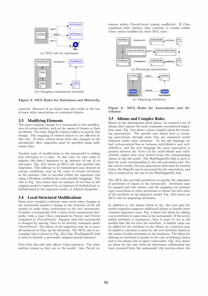
(a) MCL rule for subclasses
(b) Changing containment hierarchy
Figure 2: MCL Rules for Subclasses and Hierarchy
removed. Removal of an object may also result in the lossof some other associations or contained objects.
3.3 Modifying ElementsThe most common change to a metamodel is the modifica-tion of certain entities, such as the names of classes or theirattributes. The basic MapsTo relation suffices to specify thischange. The mapping of related objects is not affected bythis rule. If other related items have also changed in themetamodel, their migration must be specified using addi-tional rules.
Another type of modification in the metamodel is addingnew sub-types to a class. In this case, we may want tomigrate the class’s instances to an instance of one of itssub-types. Fig. 2(a) shows an MCL rule that specifies thismigration. The subtype to be instantiated may depend oncertain conditions, such as the value of certain attributesin the instance (this is encoded within the migration ruleusing a Boolean condition for each possible mapping). Therule in Fig. 2(a) states that an instance of srcClass in theoriginal model is replaced by an instance of dstSubclass1 ordstSubclass2 in the migrated model, or deleted altogether.
3.4 Local Structural ModificationsSome more complex evolution cases occur when changes inthe metamodel require a change in the structure of the oldmodels to make them conformant to the new metamodel.Consider a metamodel with a three level containment hier-archy, with a type Class contained in Parent, and Parentcontained in ParentParent. Suppose that this metamodelis changed by moving Class to be directly contained underParentParent. The intent of the migration may be to moveall instances of Class up the hierarchy. The MCL rule to ac-complish this is shown in Fig. 2(b) (the WasMappedTo linkis used to identify a previously mapped parent instance).
Note that this rule only affects Class instances. The otherentities remain as they are in the model. Any Parent in-
stances within ParentParent remain unaffected. If Classcontained other entities, they continue to remain withinClass, unless modified by other MCL rules.
(a) Rerouting associations
(b) Migrating attributes
Figure 3: MCL Rules for Associations and At-tributes
3.5 Idioms and Complex RulesBased on the descriptions given above, we created a set ofidioms that capture the most commonly encountered migra-tion cases. Fig. 3(a) shows a more complex idiom for rerout-ing associations. The specific case shown here is rerout-ing associations through ports that are contained modelelements under some container. In the old language wehad inAssociationClass-es between inSrcModel-s and inD-stModel-s, and the new language the same association ispresent between the Port-s of the outSrcModel and outD-stModel classes that were derived from the correspondingclasses in the old model. The WasMappedTo link is used tofind the node corresponding to the old association end. Forthe correct results, the new association ends must be createdbefore the MapsTo can be processed for the association, andthis is enforced by the use of the WasMappedTo link.
The MCL also provides primitives to specify the migrationof attributes of classes in the metamodel. Attributes maybe mapped just like classes, and the mapping can performtype conversions or other operations to obtain the new valueof the attribute in the migrated model. Fig. 3(b) shows anMCL rule for migrating attributes.
In addition to the idioms listed so far, the tool suite formodel migration supports additional idioms to handle othercommon migration cases. Fig. 4 shows the idiom for addinga new attribute to some class in the metamodel. If the newlyadded attribute is mandatory, then it must be set in oldmodels that did not have the attribute. A default value canbe added for the attribute in the idiom, or a function maybe added to calculate a value for the new attribute based onthe values of other attributes in the instances. The idiom fordeleting an attribute is similar to the case of deleting classesand is not shown due to space constraints. Fig. 5(a) showsan idiom for the case when an inheritance relationship hasbeen removed from the metamodel (the portion above the
90 90
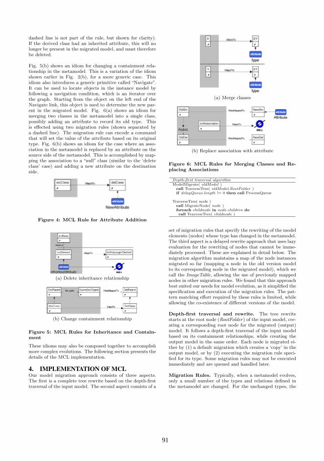
dashed line is not part of the rule, but shown for clarity).If the derived class had an inherited attribute, this will nolonger be present in the migrated model, and must thereforebe deleted.
Fig. 5(b) shows an idiom for changing a containment rela-tionship in the metamodel. This is a variation of the idiomshown earlier in Fig. 2(b), for a more generic case. Thisidiom also introduces a generic primitive called “Navigate”.It can be used to locate objects in the instance model byfollowing a navigation condition, which is an iterator overthe graph. Starting from the object on the left end of theNavigate link, this object is used to determine the new par-ent in the migrated model. Fig. 6(a) shows an idiom formerging two classes in the metamodel into a single class,possibly adding an attribute to record its old type. Thisis effected using two migration rules (shown separated bya dashed line). The migration rule can encode a commandthat will set the value of the attribute based on its originaltype. Fig. 6(b) shows an idiom for the case where an asso-ciation in the metamodel is replaced by an attribute on thesource side of the metamodel. This is accomplished by map-ping the association to a “null” class (similar to the ‘deleteclass’ case) and adding a new attribute on the destinationside.
Figure 4: MCL Rule for Attribute Addition
(a) Delete inheritance relationship
(b) Change containment relationship
Figure 5: MCL Rules for Inheritance and Contain-ment
These idioms may also be composed together to accomplishmore complex evolutions. The following section presents thedetails of the MCL implementation.
4. IMPLEMENTATION OF MCLOur model migration approach consists of three aspects.The first is a complete tree rewrite based on the depth-firsttraversal of the input model. The second aspect consists of a
(a) Merge classes
(b) Replace association with attribute
Figure 6: MCL Rules for Merging Classes and Re-placing Associations
Depth-first traversal algorithmModelMigrate( oldModel )
call TraverseTree( oldModel.RootFolder )if delayQueue.length != 0 then call ProcessQueue
TraverseTree( node )call MigrateNode( node )foreach childnode in node.children docall TraverseTree( childnode )
set of migration rules that specify the rewriting of the modelelements (nodes) whose type has changed in the metamodel.The third aspect is a delayed rewrite approach that uses lazyevaluation for the rewriting of nodes that cannot be imme-diately processed. These are explained in detail below. Themigration algorithm maintains a map of the node instancesmigrated so far (mapping a node in the old version modelto its corresponding node in the migrated model), which wecall the ImageTable, allowing the use of previously mappednodes in other migration rules. We found that this approachbest suited our needs for model evolution, as it simplified thespecification and execution of the migration rules. The pat-tern matching effort required by these rules is limited, whileallowing the co-existence of different versions of the model.
Depth-first traversal and rewrite. The tree rewritestarts at the root node (RootFolder) of the input model, cre-ating a corresponding root node for the migrated (output)model. It follows a depth-first traversal of the input modelbased on its containment relationships, while creating theoutput model in the same order. Each node is migrated ei-ther by (1) a default migration which creates a ‘copy’ in theoutput model, or by (2) executing the migration rule speci-fied for its type. Some migration rules may not be executedimmediately and are queued and handled later.
Migration Rules. Typically, when a metamodel evolves,only a small number of the types and relations defined inthe metamodel are changed. For the unchanged types, the
91 91

default ‘copy’ operation suffices in the tree rewrite describedabove. For the cases where the type has changed, a migra-tion rule is used to specify the actions necessary to migratean instance of that type into the output model.
Migration rules are specified using MCL as described abovein section 3. An MCL rule is specified for a particular (node)type in the metamodel, and consists of a pattern which mayinvolve other node types, a MapsTo relation that specifieshow the node type is migrated, optional WasMappedTo re-lation(s), and additional imperative commands and condi-tions to control node creation. The commands are impera-tive actions executed during node creation, and conditionsare Boolean expressions that control whether the migrationis allowed to happen. The WasMappedTo relation specifiesa node instance in the output model that was previouslymigrated corresponding to a certain node instance in the in-put model (maintained in the ImageTable). The migrationof a node begins by finding a migration rule for that nodetype. With the node instance as context, the rest of the ruleelements are matched by matching the appropriate nodesin the input model. If the match is not successful becausethe WasMappedTo relation is not satisfied (yet), the nodeis added to a queue to be processed later. Otherwise, thespecified node is created in the migrated (output) model,and the depth-first traversal continues.
Migration algorithm for a NodeMigrateNode( node )
let rule = FindMigrationRule( node.type )if rule == null then call DefaultMigrate( node )else call ExecuteRule( rule, node )
FindMigrationRule( nodetype )find rule in ruleSet where mapsTo.LHS.type = nodetypeif found return rule else return null
DefaultMigrate( node )let newtype = node.typeif newtype not in newMeta.typesthen throw TypeNotFoundError
let oldParent = node.parentlet newParent = ImageTable.findNewNode( oldParent )if newParent == null thencall delayQueue.addNode( node )return
let newnode = CreateNode( newtype, newParent )call CopyAttributes( node, newnode )call ImageTable.addImage( node, newnode )
ExecuteRule( rule, node )let matchResult = MatchRulePattern( rule, node )if matchResult == true then //Match succeededif Eval( rule.condition ) == false then return //Can’t applylet newtype = rule.mapsTo.RHS.typeif rule.newParent == null thenlet oldParent = node.parentlet newParent = ImageTable.findNewNode( oldParent )
let newnode = CreateNode( newtype, newParent )call CopyAttributes( node, newnode )call Eval( rule.command )call ImageTable.addImage( node, newnode )
else // Match failed, queue nodecall delayQueue.addNode( node )
Queuing and Delayed Rewrite. In certain cases, suchas a migration rule that depends on a mapping for anothernode which has not yet been migrated, the migration forthat node cannot be executed. But it may be possible toexecute the migration after some other migration rules havebeen executed. We use a delayed rewrite approach to handlethese cases, by queuing the nodes for which the migration
Delayed rewrite algorithmProcessQueue( )
let qLength = delayQueue.lengthif qLength == 0 returnfor index = 1 to qLengthlet node = delayQueue.removeTopNodecall MigrateNode( node )
if delayQueue.length < qLength then call ProcessQueue
cannot be immediately effected. The listing below describesthis algorithm. After completing the first pass of the depth-first traversal, the queued nodes are processed by callingProcessQueue. Nodes are removed from the queue (in FIFOorder), and migration is attempted again. If MigrateNodefails, the node is added back at the end of the queue. Ifthe length of the queue has changed after one pass, Pro-cessQueue is called again. The algorithm terminates whenthe queue is empty, or when a complete pass of the queuehas not changed the queue.
5. RELATED WORKOur work on model-migration has its origins in techniquesfor database schema evolution. More recently, though, eventraditional programming language evolution has been shownto share many features with model migration. Drawing fromexperience in very large scale software evolution, [6] usesseveral examples to draw analogies between tradition pro-gramming language evolution and meta-model and modelco-evolution. [3] also outlines parallels between meta-modeland model co-evolution with several other research areas,including API versioning.
Using two industrial meta-models to analyze the types ofcommon changes that occur during meta-model evolution,[9] gives a list of four major requirements that a model mi-gration tool must fulfill in order to be considered effective:(1) Reuse of migration knowledge, (2) Expressive, custommigrations, (3) Modularity, and (4) Maintaining migrationhistory. The first, reusing migration knowledge, is accom-plished by the main MCL algorithm: meta-model indepen-dent changes are automatically deduced and migration codeis automatically generated. Expressive, custom migrationsare accomplished in MCL by (1) using the meta-models di-rectly to describe the changes, and (2) allowing the userto write domain-specific code with a well-defined API. OurMCL tool also meets the last two requirements of [9]: MCLis modular in the sense that the specification of one migra-tion rule does not affect other migration rules, and the his-tory of the meta-model changes in persistent and availableto migrate models at any point in time.
[5] performs model migration by first examining a differ-ence model that records the evolution of the meta-model,and then producing ATL code that performs the model mi-gration. Their tool uses the difference model to derive twomodel transformations in ATL: one for automatically resolv-able changes, and one for unresolvable changes. MCL usesa difference model explicitly defined by the user, and usesits core algorithm to automatically deduce and resolve thebreaking resolvable changes. Changes classified as break-ing and unresolvable are also specified directly in the differ-ence model, which makes dealing with unresolvable changesstraightforward: the user defines a migration rule using agraphical notation that incorporates the two versions of themeta-model and uses a domain-specific C++ API for taskssuch as querying and setting attribute values. In [5], the user
92 92
has to refine ATL transformation rules directly in order todeal with unresolvable changes.
[7] describes the benefits of using a comparison algorithm forautomatically detecting the changes between two versions ofa meta-model, but says they cannot use this approach be-cause they use Ecore-based meta-models, which do not sup-port unique identifiers, a feature needed by their approach.Rather than have the changes between meta-model versionsdefined explicitly by the user, they slightly modify the Chan-geRecorder facility in the EMF tool set and use this to cap-ture the changes as the user edits the meta-model. Theirmigration tool then generates a model migration in the Ep-silon Transformation Language (ETL). In the case that thereare meta-model changes other than renamings, user writtencode in ETL to facilitate these changes cannot currently belinked with the ETL code generated by their migration tool.In contrast to this, MCL allows the user to define complexmigration rules with a straightforward graphical syntax, andthen generates migration code to handle these rules and linksit with the code produced by the main MCL algorithm.
[8] presents a language called COPE that allows a model mi-gration to be decomposed into modular pieces. They notethat because meta-model changes are often small, using en-dogenous model transformation techniques (i.e., the meta-models of the input and output models of the transforma-tion are exactly the same) can be beneficial, even thoughthe two meta-models are not identical in the general modelmigration problem. This use of endogenous techniques toprovide a default migration rule for elements that do notchange between meta-model versions is exactly what is donein the core MCL algorithm. However, in [8], the meta-modelchanges must be specified programmatically, as opposed toMCL, in which the meta-model changes are defined using astraightforward graphical syntax.
Rather than manually changing meta-models, the work in[13] proposes the use of QVT relations for evolving meta-models and raises the issue of combining this with a methodfor co-adapting models. While this is an interesting idea, ourMCL language uses an explicit change language to describemeta-model changes rather than model transformations.
Although not focused on meta-model or model evolution, thework in [12] is similar to our approach. The authors performthe automatic generation of a semantic analysis model froma domain-specific visual language using a special “correspon-dence” model called a meta-model triple. The connectionsprovided by the meta-model triple perform a similar role asthe MapsTo and WasMappedTo links in MCL.
6. CONCLUSIONSWe have presented the Model Change Language (MCL), ourlanguage for specifying metamodel evolution and automat-ically generating the corresponding model migration. MCLrequires the specification of only the evolved parts of a meta-model and automatically handles the persistent parts. Thespecification is done using the metamodels of the originaland evolved language, which allows domain experts to usethe same abstractions for specifying both metamodels andtheir evolution. Our implementation produces executablecode to perform model migration from the evolution speci-
fication and has been integrated with our Model-IntegratedComputing (MIC) metaprogrammable toolsuite and testedon a number DSML evolution examples of medium complex-ity. These test metamodels typically consisted of 50-100 ele-ments, and the number of migration rules were on the orderof 5-10. The examples were used in proof-of-concept demon-strations where savings in development effort were measuredwith promising results.
The model migration problem is an essential one for model-driven development and tooling, and there are several chal-lenging problems remaining in this area. Efficiency of themigration code is of paramount importance, especially onlarge-scale models. The migration idioms that we have tar-geted were based on our past experience, but it appears thatthis should be an evolving set, to be extended and refined byother developers. Thus, a continuation of this work wouldneed to address the problem of supporting such an extensiblemigration idiom set.
Acknowledgment. This work was sponsored by DARPA,under its Software Producibility Program. The views andconclusions presented are those of the authors and shouldnot be interpreted as representing official policies or endorse-ments of DARPA or the US government.
7. REFERENCES[1] A. Agrawal, T. Levendovszky, J. Sprinkle, F. Shi, and
G. Karsai. Generative programming via graphtransformations in the model-driven architecture. InOOPSLA, 2002: Workshop on Generative Techniquesin the Context of Model Driven Architecture, 2002.
[2] D. Balasubramanian, C. vanBuskirk, G. Karsai,A. Narayanan, S. Neema, B. Ness, and F. Shi.Evolving paradigms and models in multi-paradigmmodeling. Technical report, Institute for SoftwareIntegrated Systems, 2008.
[3] P. Bell. Automated transformation of statementswithin evolving domain specific languages. In 7thOOPSLA Workshop on Domain-Specific Modeling,2007.
[4] P. A. Bernstein and S. Melnik. Model Management2.0: Manipulating Richer Mappings. In SIGMOD 07,2007.
[5] A. Cicchetti, D. D. Ruscio, R. Eramo, andA. Pierantonio. Automating Co-evolution inModel-Driven Engineering. In 12th InternationalIEEE Enterprise Distributed Object ComputingConference, ECOC, pages 222–231, 2008.
[6] J.-M. Favre. Meta-models and Models Co-Evolution inthe 3D Software Space. In Proceedings of theInternational Workshop on Evolution of Large-scaleIndustrial Software Applications (ELISA) at ICSM,2003.
[7] B. Gruschko, D. S. Kolovos, and R. F. Paige. TowardsSynchronizing Models with Evolving Metamodels. InProceedings of the International Workshop onModel-Driven Software Evolution (MODSE), 2007.
[8] M. Herrmannsdoerfer, S. Benz, and E. Juergens.COPE: A Language for the Coupled Evolution ofMetamodels and Models. In MCCM Workshop atMoDELS, 2009.
[9] M. Herrmannsdoerfer, S. Benz, and E. Jurgens.
93 93
Automatability of Coupled Evolution of Metamodelsand Models in Practice. In Model Driven EngineeringLanguages and Systems, 11th InternationalConference, MoDELS, pages 645–659, 2008.
[10] MOF. Meta-Object Facility: Standards available fromObject Management Group.
[11] J. Sprinkle and G. Karsai. A domain-specific visuallanguage for domain model evolution. Journal ofVisual Languages and Computing, 15(3-4):291 – 307,2004. Domain-Specific Modeling with VisualLanguages.
[12] H. Vangheluwe and J. de Lara. Automatic generationof model-to-model transformations from rule-basedspecifications of operational semantics. In 7thOOPSLA Workshop on Domain-Specific Modeling,2007.
[13] G. Wachsmuth. Metamodel Adaptation and ModelCo-adaptation. In ECOOP 2007 - Object-OrientedProgramming, 21st European Conference, pages600–624, 2007.
94 94
Using Model-Based Testing for Testing ApplicationModels in the Context of Domain-Specific Modelling
Janne MerilinnaVTT Technical Research Centre of Finland
P.O. Box 1000,02044 Espoo, Finland+358 442 788 501
Olli-Pekka PuolitaivalVTT Technical Research Centre of Finland
P.O. Box 1100,90571 Oulu, Finland+358 400 606 293
ABSTRACTDomain-Specific Modelling (DSM) has evidently increasedproductivity and quality in software development. Althoughproductivity and quality gains are remarkable, the modelledapplications still need to be tested prior to release. Althoughtraditional testing approaches can be applied also in the context ofDSM for testing generated applications, maintaining acomprehensive test suite for all developed applications is tedious.In this paper, the feasibility of utilizing Model-Based Testing(MBT) to generate a test suite for application models is studied.The MBT is seen as a prominent approach for automaticallygenerating comprehensive test cases from models describingexternally visible behaviour of a system under testing (SUT). Westudy the feasibility by developing a domain-specific modellinglanguage and a code generator for a coffee machine laboratorialcase and apply MBT to generate a test suite for the applicationmodels. The gathered experiences indicate that there are notechnical obstacles but the feasibility of the testing approach inlarge-scale models and languages is still questionable.
Categories and Subject DescriptorsD.2.5 [Testing and Debugging]: Testing tools
General TermsExperimentation and Verification
KeywordsModel-driven development; Verification; Test generation
1. INTRODUCTIONQuite often Domain-Specific Languages (DSL) and Domain-Specific Modelling Languages (DSML) are mentioned to attain 5-10 fold productivity gains compared to traditional softwaredevelopment practices [1]. The productivity increase is primarilycaused by the Domain-Specific Modelling (DSM) basicarchitecture, i.e. DSML, a code generator and a domain-specificsoftware framework. It is also often argued that utilization ofDSM increases software quality by decreasing programs errorsamong other things [1].
While well-defined DSML promotes modelling of correctlydefined applications and in this way decreases program errors, theultimate reason for productivity gains and the decrease of programerrors is achieved via automation. Code generators are responsiblefor systematically transforming application models to source codeon the target platform. While code generators systematicallytransform application models to source code, they alsosystematically produce program errors. The difference between
code generation and manually transforming software specificationto implementation is when program errors produced in codegeneration look the same and there are many of the same kinds oferrors, manually transforming software specifications toimplementation results in various kinds of errors.
From a testing point of view, the difference is that it isalways easier to pinpoint an error which emerges frequently andsystematically compared to errors emerging in various parts andin various shapes in the source code. This has a direct impact onsource code quality. While applications produced without codegeneration need to be corrected one at a time, all errors found andcorrected in code generators contributes to the overall quality ofthe whole product family.
Although it should be easier to find errors produced by codegenerators, locating all errors in code generators is not a trivialprocess. It is highly unlikely that all paths in code generators aretraversed every time the source code is generated therefore errorsdo not reveal themselves easily. Similar to traditional applicationtesting, improving the level of quality of code generators requiresextensive test suite. In the case of code generators the test suite isa set of application models similar to compilers in traditionalsoftware development where source code is an input to thecompiler. Thus, to improve the quality of code generators requiresan extensive set of application models. In [1], iterative andincremental DSM, the development approach is argued to produceDSMLs with code generators of good enough quality. In ourearlier work [2] it was argued that a more systematic approach isrequired as the iterative and incremental development approachmay not produce an extensive enough test suite for codegenerators. Therefore an approach to produce an extensive set ofapplication models as a test suite is required.
In [2], we presented a concept for testing the whole DSMbasic architecture. The approach consists of two phases: 1)generating application models from a metamodel with anapproach of Model-Based Testing (MBT) [3], and 2) generating atest suite for generated application models with MBT. In thispaper, we further elaborate the second phase and demonstrate theapproach in a laboratorial case study. We gather the experiencesin testing application models with MBT in a laboratory case for acoffee machine for which a DSML and Python source codegenerator were developed.
This paper is structured as follows. First, the principles ofDSM and MBT are discussed to set a background and baseline forour work. Second, utilizing MBT as a means for testingapplication models is presented. Third, the application testingapproach is demonstrated in a laboratory case involving a coffeemachine. Discussion and conclusions close the paper.
9595

2. BACKGROUNDTo get an understanding of the DSM testing approach underscrutiny, the background of DSM basic architecture and MBTneeds to be known. Next, in this section, the background of DSMand MBT are discussed.
2.1 Domain-Specific ModellingIncreasing productivity in software development is largelydependent on software reuse and automation. Often the workrequired to increase productivity follows the same pattern asRoberts et al. present in [4] when reusability is considered. First, acouple of example applications are developed according totraditional means. The applications of same product family share aset of components that can be reused in the product family. Whenthe amount of reusable components increases, white-box andblack-box frameworks begin to emerge. While the frameworksmature, the application development increasingly shifts from low-level programming to utilization of the developed framework.Ultimately, the development of applications may be aboutchoosing different alternative features from a pre-defined featuretree. In the case where there is a considerable number of variationand neither feature-trees nor wizards can be utilized, domain-specific languages (DSL) and DSMLs start to emerge.
A DSM solution consists of three main parts, often describedas DSM basic architecture [1]:
A metamodel defines the syntax of a modellinglanguage. In the case of DSMLs, a metamodel mirrorsthe problem-space by providing modelling elementsfound directly from the problem domain. In practice, themetamodel also includes elements and restrictions of thetarget platform.
Code generators define the transformation rules on howto transform application models that are based on ametamodel to a source code representation.
The software framework abstracts low-level details ofthe target platform and functions as a platform on whicha code generator generates source code. Sometimes noframework is required and the generated code directlyaccesses the services and functions of the targetplatform.
Actual applications are modelled based on the modelelements and constraints of the developed metamodel. The modelscan be transformed into source code or any given representationwith generators.
2.2 Model-Based TestingThe MBT is a black-box software testing method in which testcases are automatically generated from a model describing thebehaviour of a system under testing (SUT) [3]. The MBT consistsof three phases, i.e. modelling, test generation and test execution.
In the modelling phase, behaviour of the SUT is modelledaccording to specifications of the SUT where functionalrequirements are the primary source for developing the MBTmodels [3]. The MBT being a black-box testing method, the MBTmodels are required to embody the externally visible behaviour ofthe SUT, i.e. input and output data of the SUT. The input data isused for executing the tests and output data for verifying the tests.The notation of the models can be graphical, textual or mixedwhere the notation varies from general purpose to domain-specific[5].
Test generation is based on model traversal where severaltest design algorithms are utilized for generating test cases fromthe model. For offline testing [6], i.e. generating a test suite firstand then executing it, there are two categories of test designalgorithms i.e. requirement-based criteria and coverage criteria[7]. Requirement-based criteria test design algorithms are basedon model traversal algorithms that traverse the MBT models untilall required parts of the model are visited. Coverage criteria testdesign algorithms aim to traverse the MBT models until arequired coverage criteria is fulfilled. For online testing [6]walking test design algorithms are utilized [7]. In the walking testdesign algorithm approach, each subsequent test step is decidedafter executing a preceding test step. It must be noticed, that thecoverage of the test suite can only be as extensive as the modeldescribes, i.e. parts of the program behaviour not described inmodels are not tested.
In the test execution phase, the generated test suite isexecuted against the SUT. As the software implementation isdeveloped from the same specification as the MBT models, twoopinions regarding the behaviour exist. The difference betweenthese opinions is seen as errors during test execution.
The main benefits of the MBT are the facilitation of test suitemaintenance and the coverage of the test suites. The facilitation ofthe test suite is based on the supposition that only MBT modelsare required to be kept up-to-date when the SUT evolves and thetest suite can always be updated via test generation. The increasedcoverage is based on sophisticated test design algorithms that arethe result of long time research. [3]
3. TERMS OF UTILIZING MBT FORTESTING APPLICATIONS
Testing of applications in the context of DSM can mean thefollowing aspects when the utilized metamodel restricts modellingof incorrect application models:
Does the modelled application satisfy its functional andquality requirements, i.e. is the application modelledcorrectly and according to specifications?
Does the correctly modelled application modeltransform to a source code representation correctly?
Does the correctly-modelled generated applicationfunction as modelled when executed?
In this paper, we concentrate on the two latter aspects. Thuswe assume that the application models are always correctlydefined and the reason for failure is always caused by either:
1. failure in code generation alone,
2. platform failure alone, or
3. a combination of the preceding.
Considering 1), we do not strive for white-box testing and wedo not consider source code inspection but rather strive for black-box testing. Thus in this paper we solely concentrate on testinghow the generated code integrated with the software platformfunction as a combination, i.e. black-box testing.
Such as presented in Section 2.2 the failure of a test is causedby an incorrectly implemented application or MBT model.Considering DSM, the application model is always correct(according to our terms) therefore the failure can be caused by F1)
9696

failure in code generation, F2) platform, F3) a combination of thepreceding or F4) incorrectly defined MBT models.
If we apply MBT out of its initial purpose and generate thetest suite directly from a formal specification (see illustration inFigure 1, see also [2]), i.e. an application model from whichsource code is also generated, we no longer compare during testexecution whether the modelled application is performingaccording to the specifications as we take the application model asa fact. This in no way contradicts our initial terms.
Figure 1. Using MBT for testing application models.Now, as the same model is used as an input for code
generation and test generation, we can rule out failure in F4 thusonly F1-3 remain. F2 is also ruled out from discussion in thispaper as it can be done using traditional testing approaches.Therefore a failure in code generation is the only thing remainingwhen the following terms are true:
The application model is defined according to softwarespecifications,
The application model is correctly defined consideringthe utilized metamodel, and
The test suite generated from application models isalways correct.
4. A COFFEE MACHINE AS ALABORATORY CASE
To gather experiences and the technical limitations of utilizing theMBT in testing code generators in the context of DSM, alaboratory case example involving a coffee machine is utilized.The purpose of such machines is to take coffee orders as an inputand deliver coffee as an output. There are also different kinds ofmachines where some are equipped with displays of various typesand some machines require a different amount of money as aninput whereas some make coffee for free. Nowadays there are alsovarious blends of coffees available in addition to the basiccombination of coffee and cream. Some of the most specialcoffees even have a very delicate preparation procedure thusproducing a cup of coffee might be more than just the simplestprocedure.
4.1 Tools for the Laboratory CaseAs a language workbench for developing DSMLs, codegenerators and application models, MetaCase MetaEdit+1 was
1 www.metacase.com
chosen. MetaEdit+ includes tools to define DSMLs withGOPPRR (Graph-Object-Property-Port-Role-Relationship)metamodelling language and generators with MetaEdit+Reporting Language (MERL) in addition to providing basicmodelling facilities.
For the MBT of application models, there are two differentapproaches:
develop test design algorithms within MetaEdit+environment and generate a test suite by applying thedeveloped generator, or
take advantage of existing MBT tools.
The first approach requires implementing test designalgorithms with MERL. The second approach requires exportingapplication models developed with MetaEdit+ to an external MBTtool. Exporting an application model requires implementing amodel transformation specific to a metamodel with MERL. Wechose the latter approach as developing a set of test designalgorithms was anticipated as non-trivial and troublesome and wehave had good experiences with MBT tools such as ConformiqQtronic2 (CQ), which was also chosen based on our evaluationpresented in [7].
CQ expects the Qtronic Modelling Language (QML) as aninput. QML is a variant of the Unified Modeling Language(UML) State Machine Diagram where as an action language avariant of Java is utilized. The action language is utilized fordescribing expected input and output values. From QML, CQ isable to generate test cases by applying a few coverage algorithms.CQ provides two pre-developed test scripters, which are used forgenerating Testing and Test Control Notation version 3 (TTCN-3)and Hypertext Markup Language (HTML). The TTCN-3 scripterproduces a test suite described in TTCN-3 which can be used intest execution platforms. HTML scripter produces a UMLSequence Diagram as an illustration of the test cases. In addition,CQ provides a plug-in interface for the development of customscripters.
4.2 Coffee Machine Modelling LanguageFor the coffee machine in question, Coffee Machine ModellingLanguage (CMML) was implemented with MetaEdit+. TheCMML consists of two sub-languages where the first (see lefthand side of Figure 2) is a User Interface Modelling Language(UIML) and the second language is a Coffee Making ProcessModelling Language (CMPML) (see right hand side of Figure 2).The UIML enables testers to model the users interface (UI) of thecoffee machine where the following aspects can be modelled:available sorts of coffee, the cost of a cup of coffee of a chosensort, and textual information which is displayed to the user. TheCMPML includes concepts for modelling e.g., heating a certainamount of water that is poured through a certain amount andblend of coffee to a cup of various sizes. Milk, cream, sugar etc.can be added when desired and foaming can be applied whenrequired.
2 www.conformiq.com
9797

Figure 2. Simple coffee machine modelled with CoffeeMachine Modelling Language.
For CMML, a Python source code generator was developedwhich produces complete code from models in the sense that thereis no need to modify the generated code. The generated codeenables simulation of the coffee machine behaviour in a desktopcomputer environment. The code generator is also able to producea debug version of the modelled application in addition a stand-alone version. The debug version utilizes Simple Object AccessProtocol (SOAP) Application Programming Interface (API) ofMetaEdit+ to report a change of a state during the applicationexecution back to the model where the application was generated.The change of a state is shown as a red rectangle highlighting thecurrently active state in the application models. This featureenables graphical debugging of the application.
4.3 Testing the Coffee Machine by UsingMBT
The generated code follows an architectural division of UI,control logic (CL) and cooking machine interface (CMI). The UIis responsible for taking coffee orders and money as an input, anddisplaying information to the customer. The UI provides ordersfor CL to start making the ordered coffee. The CL is responsiblefor controlling the preparation process and it closely collaborateswith CMI which simulates the physical hardware responsible forperforming various preparation- related tasks. All components areimplemented as Python threads to simulate concurrent processingand asynchronous events that are common to embedded devices.The preceding components have clearly defined interfaces topromote testability. No separate domain-specific framework existsbecause of the simplicity of the application domain.
In this laboratory case study, testing the behaviour of the CLis demonstrated. As discussed above, the CL has an interface tothe UI and CMI. The provided interface of CL towards the UIconsists of two kinds of signals i.e. pressing the coffee orderingbutton with the value of an ordered blend of drink, and the value
of coin. The required interface towards the UI consists of text tothe display signal. The required interface of CL towards CMIconsists of the order signal with a value either to add water, addcoffee, add milk, add cocoa, add cream, add sugar, warm water,and serve the coffee signal. The provided interface consists of aresponse signal with an ok/fail value as a parameter.From an implementation perspective, i.e. after code generation,the signal exchange between the components in this exampleapplication is as follows when a customer orders a hot waterproduct:
CL receives a selected blend of a drink from UI.
CL sends an add water order to CMI which immediatelystarts pouring the water to a heater.After CMI has finished pouring the water, it notifies theCL about the finished task.
After receiving the pouring complete message fromCMI, the CL notifies CMI to heat the water to 95degrees.
After CMI finishes heating the water, it notifies the CL.After receiving the heating complete message fromCMI, the CL notifies CMI to serve the coffee.
4.3.1 Model TransformationCQ expects QML as an input. As the metamodel of the CMMLand the QML are different, a model transformation from CMMLto QML is required. The model transformation can be divided intotwo main steps, i.e. transformation of the CMML objects andrelationships into the QML state machine, and transformations ofthe information contained by CMML objects into QML input andoutput signals.
In the case of transforming the coffee machine applicationmodel to QML where CL is the SUT, the transformation is asfollows. First, the QML state machine is initiated by generatingQML Start, End and Idle states. The Start state has a transition tothe Idle state. The Coffee Pressing Button objects (see the topmostentities in Figure 2) transform into QML transitions between theIdle and the Coffee decomposition states (see below). Serving theCoffee objects (see the lowest entity in Figure 2) transform intoQML states and transitions to the End state. The Coin Input objecttransforms into a looping state which loops until the correctamount of coins is received. Transformation of Coffee objectsdepends on their decomposition. Transition to Coffee objectstransform to a transition to the first object in a decompositiongraph, and the transition from the Coffee object transforms to atransition leaving from the last object in a decomposition graph.
Objects of CMPML transform to QML states. Transitionsentering to objects in CMPML transform to QML actiontransitions i.e. transitions that trigger an action represented by theconnected object. Transitions leaving the CMPML objectstransform to QML triggering transitions. Input and output valuesfor QML action and triggering transitions are generated byconsidering values and types of CMML objects.
After the model transformation, the model is in the requiredformat. The state machine part of QML is described in XMLMetadata Interchange (XMI) format and action language for inputand output transitions in QML. The result of the transformationdoes not include graphical presentation, however, for illustrationpurposes the transformed model can be manually visualized asshown in Figure 3.
9898

Figure 3. Qtronic model.In Figure 3, the state machine part of the externally visible
behaviour of the CL is presented. Input and output QML code isomitted in the figure for the sake of clarity. The left side of thefigure represents ordering the coffee product and the right siderepresents ordering the hot water product.4.3.2 Test Suite GenerationAfter the model transformation, a test engineer can choose whichtest design algorithms are to be utilized from the algorithmsprovided by the CQ. In this laboratorial example, transition andstate coverage test design algorithms were chosen. The transitioncoverage test design algorithm generates a test suite in which eachstate of the model is visited at least once. The state coverage testdesign algorithm is similar to the transition coverage test designalgorithm but visits all states. As an output format, HTML waschosen which is one the pre-made scripters provided by CQ. Now,CQ generates three test cases where one of the test cases isdepicted in HTML format as in Figure 4.
Figure 4. An illustration of a generated test case.In Figure 4 a message exchange between the CL and the
Tester is illustrated. As shown, CL receives Button pressing eventwith “hot water” parameter as an input from Tester, to which theCL reacts by sending Order with parameters “addWater” and“190” to Tester. The Tester reacts by sending Response with “ok”.After that, the CL sends Order with parameters “warmWater” and“95” to Tester which again replies with “ok”. After the CLreceives the “ok” signal, it sends “serveDrink” with value “0”Order to the Tester which closes the test case. Now, if an erroroccurs when this test is executed, it is shown as a discrepancy ofthe expected output values.
5. DISCUSSIONFor the feasibility study in utilizing MBT for testing applicationsdeveloped with DSML for a coffee machine, MetaCaseMetaEdit+ was chosen as a DSM environment whereasConformiq Qtronic was chosen as an MBT tool. To enable the testgeneration, application models export from MetaEdit+ to QC wasrequired. As the metamodels between MetaEdit+ and QC aredifferent, a model transformation was required to transformCMML to QML, which is the format required by QC.
In the coffee machine laboratory case, the modeltransformation was trivial to implement as the mapping betweenCMML and the QML is straightforward. However, this might notbe the case in real and perhaps more complex languages than the
9999
CMML. As the MBT is completely dependent on the accuracy ofthe source model, even the slightest variation between themodelled behaviour of the application models and the MBTmodels ruins the test accuracy. In the case of CMML, modeltransformation was able to be validated by visualizing the MBTmodel but this again might not be possible when more complexlanguages are considered. It might be so that the chosen approachto utilize an external MBT tool might not be the perfect choice asthe verification might just shift from testing the generatedapplications to testing the model transformations from the DSM toMBT environment. However, it must be noticed that suchtransformation has to be developed only once per language.
Another approach to utilize MBT is to replace an externalMBT tool with test design algorithms developed directly in theDSM environment. This removes the need for modeltransformation but requires implementing the test designalgorithms. Whereas by utilizing existing MBT tools that provideextensively-verified test design algorithms, now the test designalgorithms have to be implemented for every language and aquestion about the quality of custom algorithm emerges.Currently, a trade-off when to utilize an external MBT toolcompared to developing the test design algorithms by itself is amatter of debate and should be scrutinized before attempting touse MBT for testing a complete DSML, which is our ultimatetarget.
6. CONCLUSIONIndustry cases constantly attain 5-10 fold productivity gainscompared to traditional software development practices whenDSMLs with full code generation is applied in softwaredevelopment. Not only are productivity gains witnessed but alsoquality is increased in the sense of decreased program errors. Theincrease of quality is partially explainable by well-developedmodelling languages which prohibit the design of incorrectmodels but also because code generation has a remarkable impacton quality.
Although the quality increase is evident, software productscannot be released without proper testing without knowing thatthe modelling infrastructure, i.e. metamodels and code generators,is flawless. Iterative and incremental development of themodelling infrastructure is a state of the practice approach meansto produce quality languages but still there is uncertainty about thequality without systematic and extensive testing of the wholeinfrastructure. Without such systematic and extensive testingmethodology the resulting applications still need to be tested.
The contribution of this paper is a feasibility study ofapplying MBT to test the generated applications. Whiletraditionally MBT models are developed from softwarespecification parallel to implementation, we strive for applyingthe MBT to generate a test suite directly from domain-specificapplication models. In this way, the test suites are always up-to-date with the application models. In this paper, we demonstratedthe utilization of MBT to generate test suites from applicationmodels in a laboratorial case study of a coffee machine for whichDSML and Python code generator were developed. As aconclusion, the test generation seems to be technically feasible butit is still unknown if the approach is also feasible with morecomplex modelling languages.
7. REFERENCES
[1] Kelly, S. and Tolvanen, J-P. 2008. Domain-SpecificModeling: Enabling full code generation, John Wiley &Sons, ISBN 978-0-0470-03666, 427p.
[2] Merilinna, J., Puolitaival, O.-P. and Pärssinen, J. 2008.Towards Model-Based Testing of Domain-SpecificModelling Languages, The 8th OOPSLA Workshop onDomain-Specific Modeling, Nashville, TN, USA.
[3] Utting, M. and Legeard, B. 2006. Practical Model BasedTesting: A Tools Approach, Morgan Kaufmann 1st ed.,ISBN: 978-0123725011, 456p.
[4] Roberts, D., Johnson, R. 1996. Evolving Frameworks: APattern Language for Developing Object-OrientedFrameworks, Proceedings of Pattern Languages of ProgramsVol. 3 (1996).
[5] Hartman, A., Katara, M. and Olvovsky, S. 2006. Choosing atest modeling language: A survey, Haifa VerificationConference, pp. 204-218.
[6] Utting, M., Pretschner, A. and Legeard, B. 2006. Ataxonomy of model-based testing, Working papers series.University of Waikato, Department of Computer Science,Hamilton, New Zealand, University of Waitako.
[7] Puolitaival, O.-P., Luo, M. and Kanstren, T. 2008. On theProperties and Selection of Model-Based Testing tool andTechnique, 1st Workshop on Model-based Testing inPractice (MoTiP 2008), Berlin, Germany.
100100
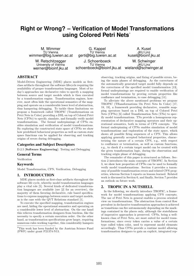
Right or Wrong? – Verification of Model Transformationsusing Colored Petri Nets∗
M. WimmerTU Vienna
G. KappelTU Vienna
A. KuselJKU Linz
[email protected]. RetschitzeggerUniversity of Vienna
J. SchoenboeckTU Vienna
W. SchwingerJKU Linz
ABSTRACTModel-Driven Engineering (MDE) places models as first-class artifacts throughout the software lifecycle requiring theavailability of proper transformation languages. Most of to-day’s approaches use declarative rules to specify a mappingbetween source and target models which is then executedby a transformation engine. Transformation engines, how-ever, most often hide the operational semantics of the map-ping and operate on a considerable lower level of abstraction,thus hampering debugging. To tackle these limitations wepropose a framework called TROPIC (Transformations onPetri Nets in Color) providing a DSL on top of Colored PetriNets (CPNs) to specify, simulate, and formally verify modeltransformations. The formal underpinnings of CPNs en-ables simulation and verification of model transformations.By exploring the constructed state space of CPNs we showhow predefined behavioral properties as well as custom statespace functions can be applied for observing and trackingorigins of errors during debugging.
Categories and Subject DescriptorsD.2.5 [Software Engineering]: Testing and Debugging
General TermsVerification
KeywordsModel Transformation, CPN, Verification, Debugging
1. INTRODUCTIONMDE places models as first-class artifacts throughout the
software life cycle, whereby model transformation languagesplay a vital role [5]. Several kinds of dedicated transforma-tion languages are available (see [2] for an overview), themajority of them favoring declarative, rule based specifica-tions to express mappings between source and target models,as is the case with the QVT Relations standard [1].
To execute the specified mapping, transformation enginesare used, hiding the operational semantics and operating ona considerable lower level of abstraction. On the one handthis relieves transformation designers from burdens, like thenecessity to specify a certain execution order. On the otherhand, as transformation specifications grow larger, requiringnumerous rules working together, this considerably hampers
∗This work has been funded by the Austrian Science Fund(FWF) under grant P21374-N13.
observing, tracking origins, and fixing of possible errors, be-ing the main phases of debugging. As the correctness ofthe automatically generated target model fully depends onthe correctness of the specified model transformation [13],formal underpinnings are required to enable verification ofmodel transformations by proving certain properties likeconfluence and termination, to ease debugging [11].
To alleviate the above mentioned problems we proposeTROPIC (TRansformations On Petri Nets In Color) [17,18, 19], a framework providing declarative, reusable map-ping operators based on a DSL on top of Colored PetriNets (CPNs) [6] called Transformation Nets (TNs) to spec-ify model transformations. TNs provide a homogenous rep-resentation of declarative mapping operators and their op-erational semantics, both in terms of CPN concepts. Theformal underpinning of CPNs enables simulation of modeltransformations and exploration of the state space, whichshows all possible firing sequences of a CPN. This allowsapplying generally accepted behavioral properties, charac-terizing the nature of a certain CPN, e.g., with respectto confluence or termination, as well as custom functions,e.g., to check if a certain target model can be created withthe given transformation logic, during the observation andtracking origin phase of debugging.
The remainder of this paper is structured as follows. Sec-tion 2 introduces the main concepts of TROPIC. In Section3, we show how properties of CPNs can be used to formallyverify model transformations. Section 4 provides a taxon-omy of possible transformation errors and related CPN prop-erties, whereas Section 5 reports on lessons learned. Relatedwork is discussed in Section 6, and finally, Section 7 providesan outlook on future work.
2. TROPIC IN A NUTSHELLIn the following, we shortly introduce TROPIC, a frame-
work for model transformations applying CPN concepts.The use of Petri Nets in general enables a process orientedview on transformations. The abstraction from control flowprevalent in declarative transformation approaches is achievedas transitions can fire autonomously depending on the mark-ings contained in the places only, although the statefulnessof imperative approaches is preserved. CPNs, being a well-known class of Petri Nets, are most suited for model trans-formations, since every token carries a value of a certaintype called token color, used to represent model elementsaccordingly. Thus CPNs provide a runtime model allowingtransformation designers to gain an explicit, integrated rep-
101101
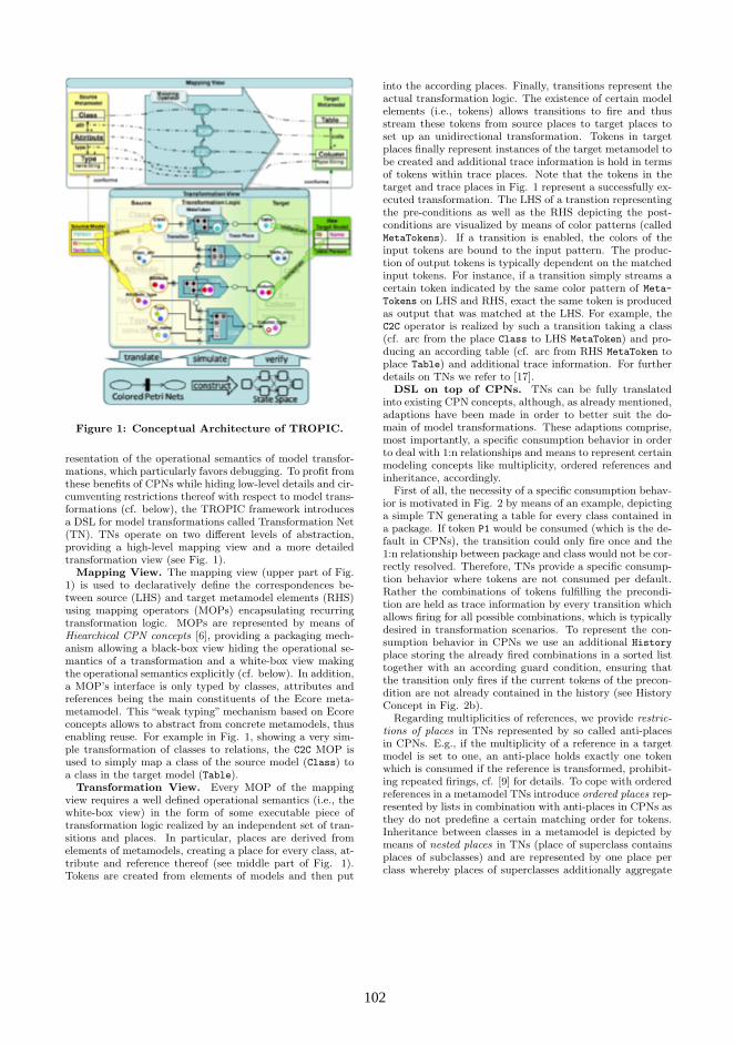
Figure 1: Conceptual Architecture of TROPIC.
resentation of the operational semantics of model transfor-mations, which particularly favors debugging. To profit fromthese benefits of CPNs while hiding low-level details and cir-cumventing restrictions thereof with respect to model trans-formations (cf. below), the TROPIC framework introducesa DSL for model transformations called Transformation Net(TN). TNs operate on two different levels of abstraction,providing a high-level mapping view and a more detailedtransformation view (see Fig. 1).
Mapping View. The mapping view (upper part of Fig.1) is used to declaratively define the correspondences be-tween source (LHS) and target metamodel elements (RHS)using mapping operators (MOPs) encapsulating recurringtransformation logic. MOPs are represented by means ofHiearchical CPN concepts [6], providing a packaging mech-anism allowing a black-box view hiding the operational se-mantics of a transformation and a white-box view makingthe operational semantics explicitly (cf. below). In addition,a MOP’s interface is only typed by classes, attributes andreferences being the main constituents of the Ecore meta-metamodel. This “weak typing” mechanism based on Ecoreconcepts allows to abstract from concrete metamodels, thusenabling reuse. For example in Fig. 1, showing a very sim-ple transformation of classes to relations, the C2C MOP isused to simply map a class of the source model (Class) toa class in the target model (Table).
Transformation View. Every MOP of the mappingview requires a well defined operational semantics (i.e., thewhite-box view) in the form of some executable piece oftransformation logic realized by an independent set of tran-sitions and places. In particular, places are derived fromelements of metamodels, creating a place for every class, at-tribute and reference thereof (see middle part of Fig. 1).Tokens are created from elements of models and then put
into the according places. Finally, transitions represent theactual transformation logic. The existence of certain modelelements (i.e., tokens) allows transitions to fire and thusstream these tokens from source places to target places toset up an unidirectional transformation. Tokens in targetplaces finally represent instances of the target metamodel tobe created and additional trace information is hold in termsof tokens within trace places. Note that the tokens in thetarget and trace places in Fig. 1 represent a successfully ex-ecuted transformation. The LHS of a transtion representingthe pre-conditions as well as the RHS depicting the post-conditions are visualized by means of color patterns (calledMetaTokens). If a transition is enabled, the colors of theinput tokens are bound to the input pattern. The produc-tion of output tokens is typically dependent on the matchedinput tokens. For instance, if a transition simply streams acertain token indicated by the same color pattern of Meta-
Tokens on LHS and RHS, exact the same token is producedas output that was matched at the LHS. For example, theC2C operator is realized by such a transition taking a class(cf. arc from the place Class to LHS MetaToken) and pro-ducing an according table (cf. arc from RHS MetaToken toplace Table) and additional trace information. For furtherdetails on TNs we refer to [17].
DSL on top of CPNs. TNs can be fully translatedinto existing CPN concepts, although, as already mentioned,adaptions have been made in order to better suit the do-main of model transformations. These adaptions comprise,most importantly, a specific consumption behavior in orderto deal with 1:n relationships and means to represent certainmodeling concepts like multiplicity, ordered references andinheritance, accordingly.
First of all, the necessity of a specific consumption behav-ior is motivated in Fig. 2 by means of an example, depictinga simple TN generating a table for every class contained ina package. If token P1 would be consumed (which is the de-fault in CPNs), the transition could only fire once and the1:n relationship between package and class would not be cor-rectly resolved. Therefore, TNs provide a specific consump-tion behavior where tokens are not consumed per default.Rather the combinations of tokens fulfilling the precondi-tion are held as trace information by every transition whichallows firing for all possible combinations, which is typicallydesired in transformation scenarios. To represent the con-sumption behavior in CPNs we use an additional Historyplace storing the already fired combinations in a sorted listtogether with an according guard condition, ensuring thatthe transition only fires if the current tokens of the precon-dition are not already contained in the history (see HistoryConcept in Fig. 2b).
Regarding multiplicities of references, we provide restric-tions of places in TNs represented by so called anti-placesin CPNs. E.g., if the multiplicity of a reference in a targetmodel is set to one, an anti-place holds exactly one tokenwhich is consumed if the reference is transformed, prohibit-ing repeated firings, cf. [9] for details. To cope with orderedreferences in a metamodel TNs introduce ordered places rep-resented by lists in combination with anti-places in CPNs asthey do not predefine a certain matching order for tokens.Inheritance between classes in a metamodel is depicted bymeans of nested places in TNs (place of superclass containsplaces of subclasses) and are represented by one place perclass whereby places of superclasses additionally aggregate
102102
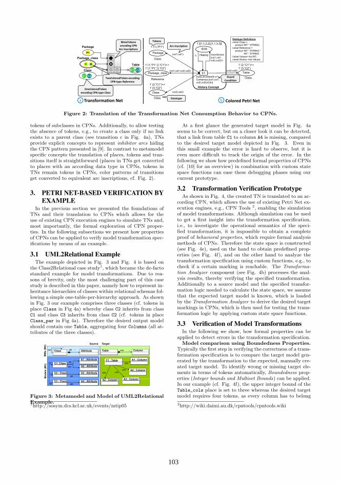
Package Arc Inscription
Tokens
1`(1,(“P1“)1`[[1,1,2,2],[1,1,3,3]]
ID35
Datatype Definitionscolset Class =
product INT * STRING;colset Reference =
MetaTokensencoding CPNArc Inscriptions
P1
Package_class
Table 1`(1,“P1“,2,“C1“)++ 1`(2,“C1“)++
PackageID35
ClassHistory(col1,val1) InsertSorted
[col1,col1,col2,col2] h
h
product INT * STRING * INT * STRING
colset Values= list INT;colset History =list Values;
Arc Inscriptions
TwoColoredToken encodingCPN type Reference
Class
C1 C2
Table
C1 C2
1 (1, P1 ,2, C1 )1`(1,“P1“,3,“C2“)
1 (2, C1 )1`(3,“C2“)
Package_class Table
ClassReference
tr1(col1,val1,col2,val2) (col2,val2)
[not(List.exists(fn x=>Contains(x,[col1,col1,
l2 l2] 4))h)]
GuardConditionCPN type Reference
D t t
1`(2,“C1“)++1`(3,“C2“)
Class
Class
(col2,val2)
col2,col2],4))h)]
History ConceptOneColoredToken
encoding CPN type Class
Colored Petri NetTransformation Neta bDatatypeClass
(col1 val1)nil1`(1,"P1")1`(1,"P1") 1`[[1,1,2,2],[1,1,3,3]]
(col1,val1)
h
Package
OneColoredPlaceHistory
InsertSorted [col1,col1,col2,col2] h1`(1,"P1",2,"C1") ++
1`(1 "P1" 3 "C2")
ID35
1`(1,"P1",2,"C1")++1`(1 "P1" 3 "C2")
1`(2,"C1")++1`(3,"C2")
(col2,val2)tr1Package_class
TwoColoredPlace
Table
OneColoredPlace[not (List.exists(fn x=>Contains(x,[col1,col1,col2,col2],4))h)]
1 (1, P1 ,3, C2 )(col1,val1,col2,val2)
1`(2 "C1") ++
1 (1, P1 ,3, C2 ) 1 (3, C2 )
1`(2 "C1")++History concept
Class
OneColoredPlace
(col2,val2)
col2,col2],4))h)]1 (2,"C1") ++ 1`(3,"C2")1 (2, C1 )++1`(3,"C2")
Figure 2: Translation of the Transformation Net Consumption Behavior to CPNs.
tokens of subclasses in CPNs. Additionally, to allow testingthe absence of tokens, e.g., to create a class only if no linkexists to a parent class (see transition c in Fig. 4a), TNsprovide explicit concepts to represent inhibitor arcs hidingthe CPN pattern presented in [9]. In contrast to metamodelspecific concepts the translation of places, tokens and tran-sitions itself is straightforward (places in TNs get convertedto places with an according data type in CPNs, tokens inTNs remain tokens in CPNs, color patterns of transitionsget converted to equivalent arc inscriptions, cf. Fig. 2).
3. PETRI NET-BASED VERIFICATION BYEXAMPLE
In the previous section we presented the foundations ofTNs and their translation to CPNs which allows for theuse of existing CPN execution engines to simulate TNs and,most importantly, the formal exploration of CPN proper-ties. In the following subsections we present how propertiesof CPNs can be applied to verify model transformation spec-ifications by means of an example.
3.1 UML2Relational ExampleThe example depicted in Fig. 3 and Fig. 4 is based on
the Class2Relational case study1, which became the de-factostandard example for model transformations. Due to rea-sons of brevity, only the most challenging part of this casestudy is described in this paper, namely how to represent in-heritance hierarchies of classes within relational schemas fol-lowing a simple one-table-per-hierarchy approach. As shownin Fig. 3 our example comprises three classes (cf. tokens inplace Class in Fig 4a) whereby class C2 inherits from classC1 and class C3 inherits from class C2 (cf. tokens in placeClass_par in Fig 4a). Therefore the desired output modelshould contain one Table, aggregating four Columns (all at-tributes of the three classes).
) Source Target
MM
s (M
2
AttributeClasspar*
*attr
A1 : Attributeattr
Table Column*cols
C1 : Table A1 : Column
Mod
els
(M1) C1: Class
A2 : Attributeattrpar
attr
C2 : Class A3 : Attributeattr
A3 : ColumnA2 C l
A4 : Columncols
cols
colscols
C3 : Class A4 : Attributeattrpar
A3 : ColumnA2 : Column
FIG 2: Transformation Net - Static Part
Figure 3: Metamodel and Model of UML2RelationalExample.1http://sosym.dcs.kcl.ac.uk/events/mtip05
At a first glance the generated target model in Fig. 4aseems to be correct, but on a closer look it can be detected,that a link from table C1 to column A4 is missing, comparedto the desired target model depicted in Fig. 3. Even inthis small example the error is hard to observe, but it iseven more difficult to track the origin of the error. In thefollowing we show how predefined formal properties of CPNs(cf. [10] for an overview) in combination with custom statespace functions can ease these debugging phases using ourcurrent prototype.
3.2 Transformation Verification PrototypeAs shown in Fig. 4, the created TN is translated to an ac-
cording CPN, which allows the use of existing Petri Net ex-ecution engines, e.g., CPN Tools 2, enabling the simulationof model transformations. Although simulation can be usedto get a first insight into the transformation specification,i.e., to investigate the operational semantics of the speci-fied transformation, it is impossible to obtain a completeproof of behavioral properties, which require formal analysismethods of CPNs. Therefore the state space is constructed(see Fig. 4e), used on the hand to obtain predefined prop-erties (see Fig. 4f), and on the other hand to analyze thetransformation specification using custom functions, e.g., tocheck if a certain marking is reachable. The Transforma-tion Analyzer component (see Fig. 4b) processes the anal-ysis results, thereby verifying the specified transformation.Additionally to a source model and the specified transfor-mation logic needed to calculate the state space, we assumethat the expected target model is known, which is loadedby the Transformation Analyzer to derive the desired targetmarkings in CPNs, which is then used for testing the trans-formation logic by applying custom state space functions.
3.3 Verification of Model TransformationsIn the following we show, how formal properties can be
applied to detect errors in the transformation specification.Model comparison using Boundedness Properties.
Typically the first step in verifying the correctness of a trans-formation specification is to compare the target model gen-erated by the transformation to the expected, manually cre-ated target model. To identify wrong or missing target ele-ments in terms of tokens automatically, Boundedness prop-erties (Integer bounds and Multiset Bounds) can be applied.In our example (cf. Fig. 4f), the upper integer bound of theTable_cols place is set to three whereas the desired targetmodel requires four tokens, as every column has to belong
2http://wiki.daimi.au.dk/cpntools/cpntools.wiki
103103

a
verify
Integer Bounds Upper Lower
Transformation Analyzer
y
load expectedtarget model
bc
translate simulate
Integer Bounds Upper Lower…Table_cols 3 0…..Upper Multi-Set Bounds …Table cols 1`(1200 "Person" 1 "name")++
predefinedstatespace
functions(properties)
custom statespace
functions
d
f
Table_cols 1 (1200, Person ,1, name )++1`(1200,"Person",2,"addr")++1`(1200,"Person",6,"custID")
…Home Markings
[1320]D d M kiexportconstruct Dead Markings
[1320]Dead Transition InstancesTransitiveClosureLinker
pconstruct
e
Figure 4: Transformation Verification Prototypeshowing the UML2Relational example
to a certain table. By inspecting the multiset bounds onerecognizes that a link to the column A4 originating from anattribute of class C3 is missing. If such erroneous parts ofthe target model are detected, the owning target place (seeerror sign besides the Table_cols place in Fig. 4a) as wellas the transitions that produce tokens in these places arehighlighted in the TN. Unfortunately, numerous transitionsare involved in creating the Table_cols link in our example,which hampers finding the actual origin of the error.
Transition Error Detection using Liveness Prop-erties. Errors in the transformation specification occur ifeither a transition is specified incorrectly or the source modelis incorrect. Both cases might lead to transitions which arenever enabled during execution, so called Dead TransitionInstances or L0-Liveness. The state space report in Fig. 4fshows that transition b in the TN is a Dead Transition In-stance, which is therefore marked with an error sign. Theintention of transition b in our example is to calculate thetransitive closure, thus there should be an additional linkfrom class C to class A as class C also inherits from class A
(see Fig 3). On investigating the LHS of transition b in Fig.4 we see that the inheritance hierarchy is faulty; the patternspecifies that class X (white color) is parent of class Y (blackcolor) and class Z (gray color). To fix the color pattern weneed to change outer and inner color of the second Meta-Token; now class X (white color) is parent of class Y (blackcolor), and X is again parent of class Z (gray color). Afterfixing the error, the state space can be constructed againand will not contain dead transitions anymore.
Termination and Confluence Verification using Deadand Home Markings. A transformation specification mustalways be able to terminate, thus the state space has to con-tain at least one Dead Marking. This is typically ensured by
the history concept of TNs, which prevents firing for recur-ring combinations. Finally it has to be ensured that a deadmarking is always reachable, meaning that a transformationspecification is confluent, which can be checked by the HomeMarking property requiring that a marking M can be reachedfrom any other reachable marking.
The generated report in Fig. 4f shows that in our exam-ple a single Home Marking is available which is equal to thesingle Dead Marking (both identified by the marking 1320),meaning that the transformation specification always termi-nates. To achieve a correct transformation result, an equalHome Marking and Dead Marking is a necessary but not asufficient condition, as it cannot be ensured that this mark-ing represents the desired target model. By exploring theconstructed state space using custom functions it is possibleto detect if a certain marking is reachable with the specifiedtransformation logic, i.e., the target marking derived fromthe desired target model. If it is, and the marking is equal toboth, Home Marking and Dead Marking, it is ensured thatthe desired target model can be created with the specifiedtransformation logic in any case.
4. CPN PROPERTIES FOR MODEL TRANS-FORMATIONS
By applying and analyzing behavioral properties of CPNsin different case studies we tried to figure out which proper-ties are useful in the context of model transformation veri-fication and which kind of errors can be detected. The pro-posed taxonomy (see Fig. 5) investigates possible locationsof errors, classifies typical model transformations errors andshows which properties are useful for their detection. Thetaxonomy extends our taxonomy presented in [8], focusingon how common QVT pitfalls can be detected in TROPIC.
Location Granularity Type Transformation Net CPN Property
Metamodel
Syntax Error (non conformance to MMM)
Semantic Error(e g missing constraints)
Model
(e.g. missing constraints)
Syntax Error (non conformance to MM)
LivenessSemantic Errorwrong tokens (e.g. , two colored token with equal
Boundedness(e.g. , self links, inheritance)
wrong source MM element LivenessBoundedness
colored token with equal inner/outer color)
wrong arc from place to transition
Intra‐Rule
wrong/too strong/too weak matching pattern
non‐satisfiable matching pattern
BoundednessReachability
Liveness
LHS wrong/incomplete color pattern in LHS of transition
non‐satisfiable color pattern with respect to MM
Transformation
Rule
RHSwrong target MM element
wrong instantiation of target elements
ReachabilityBoundedness
wrong arc from transition to target place
wrong/incomplete color pattern in RHS of transition
Logic Source MM
coverage
missing/redundant source MM elements
wrong intermediate Reachability
elements pattern in RHS of transition
missing/redundant arcs from source place to transition
wrong tokens in/wrong
Inter‐Rule
Target MM
coveragemissing/redundant target
MM elements
results/dependencies Boundedness
hungry transitions sharing Home Statenon‐determinism/non‐
connection to trace place
missing/redundant arcs from transition to target place
non‐termination Dead State
hungry transitions sharing same source place
Home StatePersistence
non determinism/nonconfluence
loops producing new colored tokens
Runtime behavior
Figure 5: Taxonomy of Transformation Errors andCPN Properties.
During specification of model transformations there arethree possible locations of errors, either in (i) the meta-model, (ii) the model, or (iii) the transformation logic. Thedetection of errors in the metamodel is in general out ofscope of transformation languages. As we explicitly repre-sent model elements—in contrast to other transformationlanguages—as tokens in TNs, semantic errors in the modelcan be detected by the liveness or boundedness property.For example, an incorrect source model (e.g., self links rep-
104104
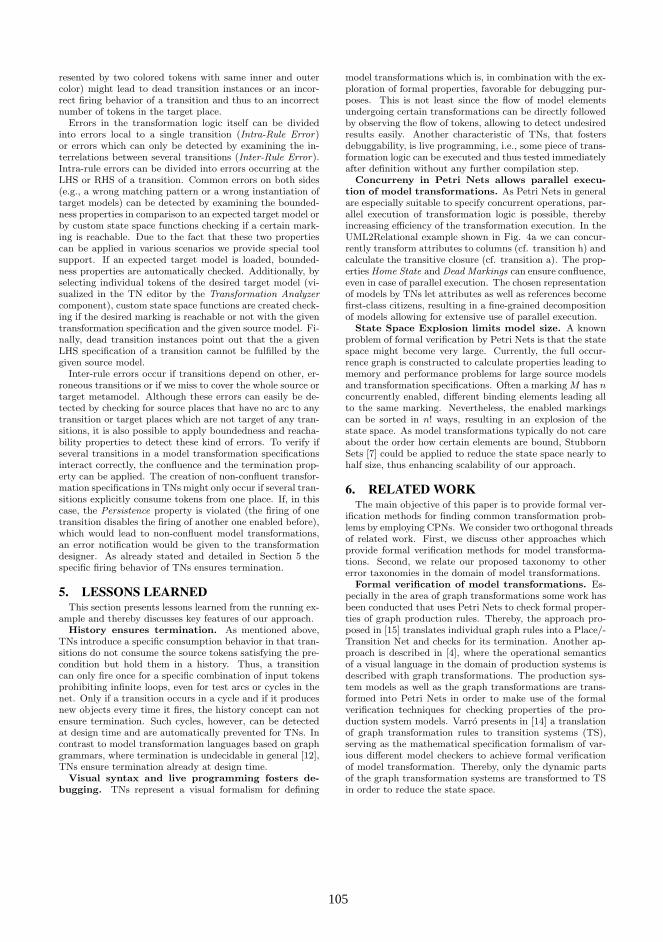
resented by two colored tokens with same inner and outercolor) might lead to dead transition instances or an incor-rect firing behavior of a transition and thus to an incorrectnumber of tokens in the target place.
Errors in the transformation logic itself can be dividedinto errors local to a single transition (Intra-Rule Error)or errors which can only be detected by examining the in-terrelations between several transitions (Inter-Rule Error).Intra-rule errors can be divided into errors occurring at theLHS or RHS of a transition. Common errors on both sides(e.g., a wrong matching pattern or a wrong instantiation oftarget models) can be detected by examining the bounded-ness properties in comparison to an expected target model orby custom state space functions checking if a certain mark-ing is reachable. Due to the fact that these two propertiescan be applied in various scenarios we provide special toolsupport. If an expected target model is loaded, bounded-ness properties are automatically checked. Additionally, byselecting individual tokens of the desired target model (vi-sualized in the TN editor by the Transformation Analyzercomponent), custom state space functions are created check-ing if the desired marking is reachable or not with the giventransformation specification and the given source model. Fi-nally, dead transition instances point out that the a givenLHS specification of a transition cannot be fulfilled by thegiven source model.
Inter-rule errors occur if transitions depend on other, er-roneous transitions or if we miss to cover the whole source ortarget metamodel. Although these errors can easily be de-tected by checking for source places that have no arc to anytransition or target places which are not target of any tran-sitions, it is also possible to apply boundedness and reacha-bility properties to detect these kind of errors. To verify ifseveral transitions in a model transformation specificationsinteract correctly, the confluence and the termination prop-erty can be applied. The creation of non-confluent transfor-mation specifications in TNs might only occur if several tran-sitions explicitly consume tokens from one place. If, in thiscase, the Persistence property is violated (the firing of onetransition disables the firing of another one enabled before),which would lead to non-confluent model transformations,an error notification would be given to the transformationdesigner. As already stated and detailed in Section 5 thespecific firing behavior of TNs ensures termination.
5. LESSONS LEARNEDThis section presents lessons learned from the running ex-
ample and thereby discusses key features of our approach.History ensures termination. As mentioned above,
TNs introduce a specific consumption behavior in that tran-sitions do not consume the source tokens satisfying the pre-condition but hold them in a history. Thus, a transitioncan only fire once for a specific combination of input tokensprohibiting infinite loops, even for test arcs or cycles in thenet. Only if a transition occurs in a cycle and if it producesnew objects every time it fires, the history concept can notensure termination. Such cycles, however, can be detectedat design time and are automatically prevented for TNs. Incontrast to model transformation languages based on graphgrammars, where termination is undecidable in general [12],TNs ensure termination already at design time.
Visual syntax and live programming fosters de-bugging. TNs represent a visual formalism for defining
model transformations which is, in combination with the ex-ploration of formal properties, favorable for debugging pur-poses. This is not least since the flow of model elementsundergoing certain transformations can be directly followedby observing the flow of tokens, allowing to detect undesiredresults easily. Another characteristic of TNs, that fostersdebuggability, is live programming, i.e., some piece of trans-formation logic can be executed and thus tested immediatelyafter definition without any further compilation step.
Concurreny in Petri Nets allows parallel execu-tion of model transformations. As Petri Nets in generalare especially suitable to specify concurrent operations, par-allel execution of transformation logic is possible, therebyincreasing efficiency of the transformation execution. In theUML2Relational example shown in Fig. 4a we can concur-rently transform attributes to columns (cf. transition h) andcalculate the transitive closure (cf. transition a). The prop-erties Home State and Dead Markings can ensure confluence,even in case of parallel execution. The chosen representationof models by TNs let attributes as well as references becomefirst-class citizens, resulting in a fine-grained decompositionof models allowing for extensive use of parallel execution.
State Space Explosion limits model size. A knownproblem of formal verification by Petri Nets is that the statespace might become very large. Currently, the full occur-rence graph is constructed to calculate properties leading tomemory and performance problems for large source modelsand transformation specifications. Often a marking M has nconcurrently enabled, different binding elements leading allto the same marking. Nevertheless, the enabled markingscan be sorted in n! ways, resulting in an explosion of thestate space. As model transformations typically do not careabout the order how certain elements are bound, StubbornSets [7] could be applied to reduce the state space nearly tohalf size, thus enhancing scalability of our approach.
6. RELATED WORKThe main objective of this paper is to provide formal ver-
ification methods for finding common transformation prob-lems by employing CPNs. We consider two orthogonal threadsof related work. First, we discuss other approaches whichprovide formal verification methods for model transforma-tions. Second, we relate our proposed taxonomy to othererror taxonomies in the domain of model transformations.
Formal verification of model transformations. Es-pecially in the area of graph transformations some work hasbeen conducted that uses Petri Nets to check formal proper-ties of graph production rules. Thereby, the approach pro-posed in [15] translates individual graph rules into a Place/-Transition Net and checks for its termination. Another ap-proach is described in [4], where the operational semanticsof a visual language in the domain of production systems isdescribed with graph transformations. The production sys-tem models as well as the graph transformations are trans-formed into Petri Nets in order to make use of the formalverification techniques for checking properties of the pro-duction system models. Varro presents in [14] a translationof graph transformation rules to transition systems (TS),serving as the mathematical specification formalism of var-ious different model checkers to achieve formal verificationof model transformation. Thereby, only the dynamic partsof the graph transformation systems are transformed to TSin order to reduce the state space.
105105
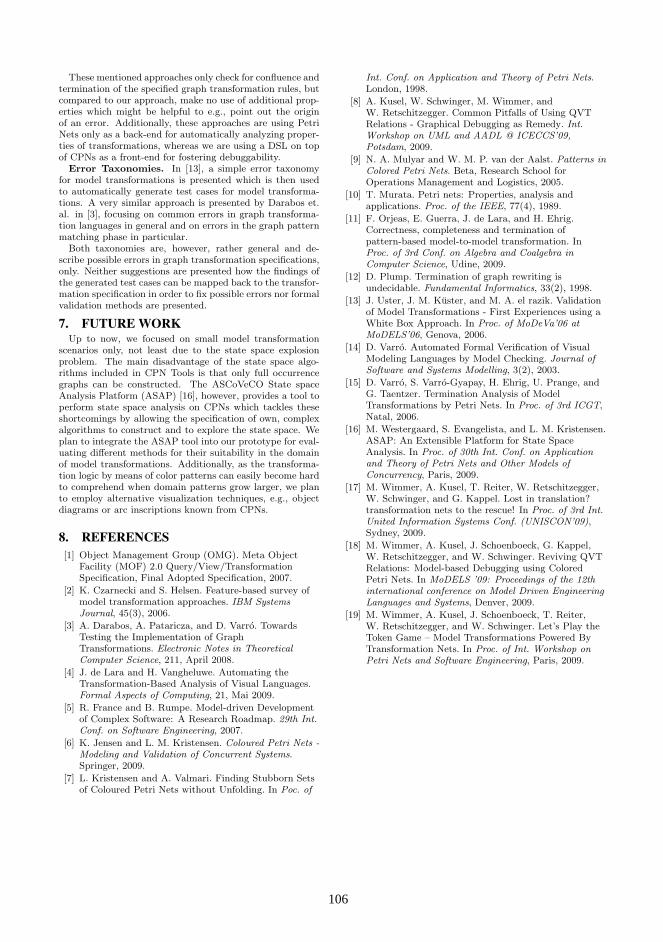
These mentioned approaches only check for confluence andtermination of the specified graph transformation rules, butcompared to our approach, make no use of additional prop-erties which might be helpful to e.g., point out the originof an error. Additionally, these approaches are using PetriNets only as a back-end for automatically analyzing proper-ties of transformations, whereas we are using a DSL on topof CPNs as a front-end for fostering debuggability.
Error Taxonomies. In [13], a simple error taxonomyfor model transformations is presented which is then usedto automatically generate test cases for model transforma-tions. A very similar approach is presented by Darabos et.al. in [3], focusing on common errors in graph transforma-tion languages in general and on errors in the graph patternmatching phase in particular.
Both taxonomies are, however, rather general and de-scribe possible errors in graph transformation specifications,only. Neither suggestions are presented how the findings ofthe generated test cases can be mapped back to the transfor-mation specification in order to fix possible errors nor formalvalidation methods are presented.
7. FUTURE WORKUp to now, we focused on small model transformation
scenarios only, not least due to the state space explosionproblem. The main disadvantage of the state space algo-rithms included in CPN Tools is that only full occurrencegraphs can be constructed. The ASCoVeCO State spaceAnalysis Platform (ASAP) [16], however, provides a tool toperform state space analysis on CPNs which tackles theseshortcomings by allowing the specification of own, complexalgorithms to construct and to explore the state space. Weplan to integrate the ASAP tool into our prototype for eval-uating different methods for their suitability in the domainof model transformations. Additionally, as the transforma-tion logic by means of color patterns can easily become hardto comprehend when domain patterns grow larger, we planto employ alternative visualization techniques, e.g., objectdiagrams or arc inscriptions known from CPNs.
8. REFERENCES[1] Object Management Group (OMG). Meta Object
Facility (MOF) 2.0 Query/View/TransformationSpecification, Final Adopted Specification, 2007.
[2] K. Czarnecki and S. Helsen. Feature-based survey ofmodel transformation approaches. IBM SystemsJournal, 45(3), 2006.
[3] A. Darabos, A. Pataricza, and D. Varro. TowardsTesting the Implementation of GraphTransformations. Electronic Notes in TheoreticalComputer Science, 211, April 2008.
[4] J. de Lara and H. Vangheluwe. Automating theTransformation-Based Analysis of Visual Languages.Formal Aspects of Computing, 21, Mai 2009.
[5] R. France and B. Rumpe. Model-driven Developmentof Complex Software: A Research Roadmap. 29th Int.Conf. on Software Engineering, 2007.
[6] K. Jensen and L. M. Kristensen. Coloured Petri Nets -Modeling and Validation of Concurrent Systems.Springer, 2009.
[7] L. Kristensen and A. Valmari. Finding Stubborn Setsof Coloured Petri Nets without Unfolding. In Poc. of
Int. Conf. on Application and Theory of Petri Nets.London, 1998.
[8] A. Kusel, W. Schwinger, M. Wimmer, andW. Retschitzegger. Common Pitfalls of Using QVTRelations - Graphical Debugging as Remedy. Int.Workshop on UML and AADL @ ICECCS’09,Potsdam, 2009.
[9] N. A. Mulyar and W. M. P. van der Aalst. Patterns inColored Petri Nets. Beta, Research School forOperations Management and Logistics, 2005.
[10] T. Murata. Petri nets: Properties, analysis andapplications. Proc. of the IEEE, 77(4), 1989.
[11] F. Orjeas, E. Guerra, J. de Lara, and H. Ehrig.Correctness, completeness and termination ofpattern-based model-to-model transformation. InProc. of 3rd Conf. on Algebra and Coalgebra inComputer Science, Udine, 2009.
[12] D. Plump. Termination of graph rewriting isundecidable. Fundamental Informatics, 33(2), 1998.
[13] J. Uster, J. M. Kuster, and M. A. el razik. Validationof Model Transformations - First Experiences using aWhite Box Approach. In Proc. of MoDeVa’06 atMoDELS’06, Genova, 2006.
[14] D. Varro. Automated Formal Verification of VisualModeling Languages by Model Checking. Journal ofSoftware and Systems Modelling, 3(2), 2003.
[15] D. Varro, S. Varro-Gyapay, H. Ehrig, U. Prange, andG. Taentzer. Termination Analysis of ModelTransformations by Petri Nets. In Proc. of 3rd ICGT,Natal, 2006.
[16] M. Westergaard, S. Evangelista, and L. M. Kristensen.ASAP: An Extensible Platform for State SpaceAnalysis. In Proc. of 30th Int. Conf. on Applicationand Theory of Petri Nets and Other Models ofConcurrency, Paris, 2009.
[17] M. Wimmer, A. Kusel, T. Reiter, W. Retschitzegger,W. Schwinger, and G. Kappel. Lost in translation?transformation nets to the rescue! In Proc. of 3rd Int.United Information Systems Conf. (UNISCON’09),Sydney, 2009.
[18] M. Wimmer, A. Kusel, J. Schoenboeck, G. Kappel,W. Retschitzegger, and W. Schwinger. Reviving QVTRelations: Model-based Debugging using ColoredPetri Nets. In MoDELS ’09: Proceedings of the 12thinternational conference on Model Driven EngineeringLanguages and Systems, Denver, 2009.
[19] M. Wimmer, A. Kusel, J. Schoenboeck, T. Reiter,W. Retschitzegger, and W. Schwinger. Let’s Play theToken Game – Model Transformations Powered ByTransformation Nets. In Proc. of Int. Workshop onPetri Nets and Software Engineering, Paris, 2009.
106106

A Tooling Environment for Quality-Driven Domain-SpecificModelling
Janne MerilinnaVTT Technical Research Centre of Finland
P.O. Box 100002044 Espoo, Finland
Tomi RätyVTT Technical Research Centre of Finland
P.O. Box 110090571 Oulu, Finland
ABSTRACTThere is an increasing need for reducing costs and improvingquality in software development. One of the means to reduce costsis to increase productivity by utilizing Domain-SpecificModelling (DSM). Industry cases consistently show a 5-10 foldincrease in productivity when DSM is applied, in addition to adecrease of errors in generated code. In order to improve qualityand especially desired quality attributes, e.g., performance andreliability, quality requirements must be considered in everydevelopment phase. Also a trace link from quality requirementsdefinitions to implementation and tests has to be maintained toassure that the resulting application truly satisfies therequirements. As Model-Driven Development is heavilydependent on provided tool support, a tooling environment thatenables quality-driven DSM would be useful. Thus in this paper,we study if MetaCase MetaEdit+ language workbench can beutilized as such by developing a code generator and a domain-specific modelling language for a laboratory case of stream-oriented computing systems. We found that the chosenenvironment is appropriate for an industrial application of quality-driven DSM.
KeywordsModel-Driven Development, quality attributes, traceability
1. INTRODUCTIONWhereas development costs must be abated in softwaredevelopment, at the same time customers demand products of everhigher quality. Today, it is not enough for software applications tosatisfy demanding functional requirements. Rather, qualityattributes such as the performance and reliability of an applicationalso have to be planned, predicted, implemented and upondelivery it must attain its satisfactory and planned level of quality.Productivity must also be improved in software development todecrease development costs while achieving the desired quality.
One of the means to increase productivity is to applymodelling in software development. Model-Driven Development(MDD) treats models as first class design entities in whichmodelling is argued to provide a view to a complex problem andits solutions, an approach which is less risky, cheaper to develop,and easier to understand than the implementation of the actualtarget system [1]. In particular, the application of Domain-Specific Modelling (DSM) often results in a 5- to 10-fold increasein productivity in industrial cases in comparison to traditionalpractices [2].
To achieve products of desired quality, quality requirementshave to be taken into account in software design and ultimately inan implementation. Much effort has been placed in developingmethods and techniques that take quality requirements into
account in software architecture development [3][4][5] andrespectively to evaluate software quality from architecturalmodels [6][7][8]. Whichever method is applied in architecturedevelopment where quality is of the importance, the followingpieces must be employed for quality-driven development: 1)precise definitions of quality requirements, 2) a list of alternativedesign solutions to achieve such requirements, 3) linkage of therequirements and the design fragments that promote certainqualities, and 4) a method for utilizing such fragments in softwaredesign [9]. The preceding pieces must be accompanied withtracing of quality requirements. This is an activity of identifyingrequirements in the following work products through the entiredevelopment process [10]. The tracing improves all kinds ofimpact analysis from the measurable acceptance criteria of eachquality requirement to the release of a software application [10].
To maintain a trace link all the way from qualityrequirements through architecture models to implementation, alink should not be broken at the model level. The models shouldalso be automatically transformed into implementation to avoid anunnecessary phase of manually transforming models into sourcecode. Considering the preceding statement, the subsequentrequirements can be formulated for quality-driven DSM (QDSM):1) quality requirements have to be explicitly expressed in models,2) there must be a means to affect the quality attributes and theirimpact on quality should be observable in models, 3) there shouldbe methods and techniques available to evaluate and test themodels and the result of the evaluation and measurements shouldbe presented in models to facilitate traceability of qualityrequirements. Finally, 4) full code generation from models has tobe possible to enable testing of the models and to produce therelease version of a modelled application.
Success of QDSM extensively lies in the provided toolsupport. Although there are tools to support quality requirementsdescriptions in architecture models [11], support for quality-driven development of architectures [12] and even support forarchitecture evaluation [11], we have not found a mature industry-ready integrated DSM tooling environment that demonstratesQDSM. Thus in this paper, we study if MetaCase MetaEdit+,which is a language workbench for developing code generatorsand domain-specific modelling languages (DSMLs) with ametamodelling approach, can be utilized as such an environmentby developing a demonstration.
With MetaEdit+, we have developed a DSML and Pythoncode generator which enables full code generation for simulatingstream-oriented computing systems. The tool environment and thedeveloped language provides: 1) a means to define qualityrequirements and to connect the requirements to correspondingmodel entities, 2) automated pattern recognition to provide adesign rationale from the quality perspective, 3) measurementmechanisms for testing execution-time quality attributes [13] such
107107

as performance and reliability, 4) linkage between themeasurement mechanisms and quality requirements to explicitlyexpress if the quality requirements are satisfied, and 5) anoptimization assistant that guides the modeller in achieving thedesired qualities. We demonstrate the tool environment formodelling a system that initially does not satisfy its qualityrequirements, but with the help of the provided facilities ofQDSM, is refined to fulfil the requirements.
This paper is structured as follows. First, requirements forQDSM including a state-of-the-art means for supporting quality-driven software development are discussed in Section 2. Second, alaboratory case including its modelling language and a codegenerator are introduced in Section 3. After that, in Section 4 thetool environment is demonstrated by transforming a model thatdoes not satisfy its quality requirements into a system thatcompletely satisfies the requirements. Discussion and conclusionsclose the paper.
2. Requirements for Quality-Driven Domain-Specific ModellingThe goal of QDSM is to entail in a single model the 1) qualityrequirements, 2) what has been done to satisfy the requirements,and 3) an evaluation and test results. By enabling this, tracing ofquality requirements to implementation including test results isfacilitated. Next, requirements and a state-of-the-art means forQDSM are more precisely discussed.
2.1 Expressing Quality RequirementsQuality requirements must explicitly be identified, divided andformalized to enable the designation of what parts of theapplication models are responsible for them and what are themeans to validate the satisfaction of requirements. ConsideringMDD, quality requirements have to be declared not only instandalone requirements engineering tools but also in themodelling environment. Quality requirements have to beconnectable to the modelling entities to maintain the explicit linkbetween the requirements and the corresponding model entities.
There are several languages for the modelling of functionaland quality requirements. These are evaluated in [14] and [15].Also there are ontologies [16] and experimental visualizationtechniques [17] as well as existing tool support for requirementsdescription, such as with IBM Rational RequisitePro and IBMRational DOORS. Despite the format, it is of importance that thequality requirements should be defined in such way that theirachievement can be verified, i.e. requirements should bemeasurable and they should include qualification requirementsand acceptance criteria [10]. Such a template for describingquality requirements has been introduced by Ebert [10] fordocumenting quality goals.
2.2 Means to Affect the Quality AttributesThe utilized modelling language should have mechanisms toaffect the quality attributes and there should be an enumeration ofdesign approaches which enable to have an impact on qualityattributes. It is also important that the impact of these mechanismson the quality attributes should be made explicit to bridge thediscrepancy between the quality requirements and the promotedquality attributes [18].
Patterns are considered as one of the means to express andaffect the qualities of a software system. This argument is basedon the definition of patterns. Alexander [19] defines patterns as“…a rule which establishes a relationship between context, a
system of forces which arises in that context, and a configurationwhich allows these forces to resolve themselves in that context.”Thus, patterns can also be seen as a solution for balancing forcesrelated to qualities in a certain context. Currently, there is noextensive list of qualities that patterns promote. Nevertheless,some preliminary categorizations can be found from [3]. There aretechniques, such as the goal-driven model transformationtechnique, that strives to provide a bridge between userrequirements and design models [20] in which utilized patternsare based on scrutinizing the intent of patterns and dividing theirintents into functional and quality parts. Then the mostappropriate pattern is chosen for the situation at hand [21].
In addition to explicitly expressing the design rationale fromthe quality perspective, support for the modeller for the QDSM isrecommended. Such support should include a model evaluationassistant that generates hints to optimize the system according tothe quality requirements. Such hints can be based on e.g.,architectural tactics [9] and patterns that promote the requiredquality requirements [3][12].
2.3 Evaluation and TestingModels ultimately need to be evaluated and tested. There are afew software architecture evaluation methods that focus on certainquality attributes. The AEM method [7] concentrates onadaptability evaluation, whereas the IEE method [8] focuses onintegrability and extensibility. There are also methods such asATAM [6] that consider a set of quality attributes in theevaluation. While most of the evaluation methods are scenario-based or prediction methods, it is argued that quality can also beevaluated by inspecting what patterns are applied in models [12].
After evaluation, the models have to be tested by executingthem to verify if the evaluation is tenable. Testing can only beperformed for execution-time qualities [13] based on sheerdefinition. The generated implementation has to be monitored andmeasured from those parts in which quality requirements areconnected to find out whether the execution-time qualityrequirements are satisfied. To support QDSM, the results of thetests need to be reported back to models. This enables themodeller to see measured values of quality attributes, and whetherthe quality requirements have been satisfied.
3. Domain-Specific Modelling Language forM-Net Laboratory CaseTo demonstrate QDSM in MetaCase MetaEdit+, a laboratory caseis utilized. The laboratory case is a stream-oriented computingsystem. For the laboratory case M-Net modelling languageincluding a complete Python code generator was developed whichenables complete code generation from domain-specific models. Itmust be noticed that the utilized laboratory case is only alaboratorial example of real stream-oriented computing systemand is utilized only to simulate such a system.
3.1 The DomainStream-oriented computing systems are characterized by parallelcomputing components that process potentially infinite sequencesof data [22]. The purpose of such a system is to read data from adata source, manipulate the data and store or forward thecomputed data. Briefly, the system forms a pipes- and filters-based system which enables parallel processing of data. Similarsystems are common, e.g., in video and image processing.
The domain of the laboratory case includes the followingconcepts (concepts in italic). Filters manipulate the input data and
108108
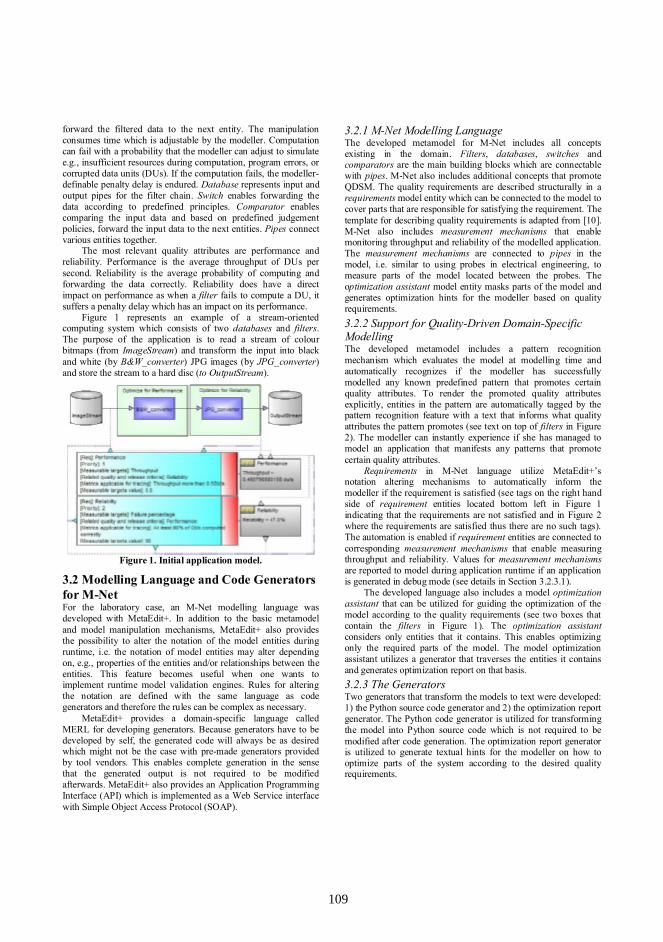
forward the filtered data to the next entity. The manipulationconsumes time which is adjustable by the modeller. Computationcan fail with a probability that the modeller can adjust to simulatee.g., insufficient resources during computation, program errors, orcorrupted data units (DUs). If the computation fails, the modeller-definable penalty delay is endured. Database represents input andoutput pipes for the filter chain. Switch enables forwarding thedata according to predefined principles. Comparator enablescomparing the input data and based on predefined judgementpolicies, forward the input data to the next entities. Pipes connectvarious entities together.
The most relevant quality attributes are performance andreliability. Performance is the average throughput of DUs persecond. Reliability is the average probability of computing andforwarding the data correctly. Reliability does have a directimpact on performance as when a filter fails to compute a DU, itsuffers a penalty delay which has an impact on its performance.
Figure 1 represents an example of a stream-orientedcomputing system which consists of two databases and filters.The purpose of the application is to read a stream of colourbitmaps (from ImageStream) and transform the input into blackand white (by B&W_converter) JPG images (by JPG_converter)and store the stream to a hard disc (to OutputStream).
Figure 1. Initial application model.
3.2 Modelling Language and Code Generatorsfor M-NetFor the laboratory case, an M-Net modelling language wasdeveloped with MetaEdit+. In addition to the basic metamodeland model manipulation mechanisms, MetaEdit+ also providesthe possibility to alter the notation of the model entities duringruntime, i.e. the notation of model entities may alter dependingon, e.g., properties of the entities and/or relationships between theentities. This feature becomes useful when one wants toimplement runtime model validation engines. Rules for alteringthe notation are defined with the same language as codegenerators and therefore the rules can be complex as necessary.
MetaEdit+ provides a domain-specific language calledMERL for developing generators. Because generators have to bedeveloped by self, the generated code will always be as desiredwhich might not be the case with pre-made generators providedby tool vendors. This enables complete generation in the sensethat the generated output is not required to be modifiedafterwards. MetaEdit+ also provides an Application ProgrammingInterface (API) which is implemented as a Web Service interfacewith Simple Object Access Protocol (SOAP).
3.2.1 M-Net Modelling LanguageThe developed metamodel for M-Net includes all conceptsexisting in the domain. Filters, databases, switches andcomparators are the main building blocks which are connectablewith pipes. M-Net also includes additional concepts that promoteQDSM. The quality requirements are described structurally in arequirements model entity which can be connected to the model tocover parts that are responsible for satisfying the requirement. Thetemplate for describing quality requirements is adapted from [10].M-Net also includes measurement mechanisms that enablemonitoring throughput and reliability of the modelled application.The measurement mechanisms are connected to pipes in themodel, i.e. similar to using probes in electrical engineering, tomeasure parts of the model located between the probes. Theoptimization assistant model entity masks parts of the model andgenerates optimization hints for the modeller based on qualityrequirements.3.2.2 Support for Quality-Driven Domain-SpecificModellingThe developed metamodel includes a pattern recognitionmechanism which evaluates the model at modelling time andautomatically recognizes if the modeller has successfullymodelled any known predefined pattern that promotes certainquality attributes. To render the promoted quality attributesexplicitly, entities in the pattern are automatically tagged by thepattern recognition feature with a text that informs what qualityattributes the pattern promotes (see text on top of filters in Figure2). The modeller can instantly experience if she has managed tomodel an application that manifests any patterns that promotecertain quality attributes.
Requirements in M-Net language utilize MetaEdit+’snotation altering mechanisms to automatically inform themodeller if the requirement is satisfied (see tags on the right handside of requirement entities located bottom left in Figure 1indicating that the requirements are not satisfied and in Figure 2where the requirements are satisfied thus there are no such tags).The automation is enabled if requirement entities are connected tocorresponding measurement mechanisms that enable measuringthroughput and reliability. Values for measurement mechanismsare reported to model during application runtime if an applicationis generated in debug mode (see details in Section 3.2.3.1).
The developed language also includes a model optimizationassistant that can be utilized for guiding the optimization of themodel according to the quality requirements (see two boxes thatcontain the filters in Figure 1). The optimization assistantconsiders only entities that it contains. This enables optimizingonly the required parts of the model. The model optimizationassistant utilizes a generator that traverses the entities it containsand generates optimization report on that basis.3.2.3 The GeneratorsTwo generators that transform the models to text were developed:1) the Python source code generator and 2) the optimization reportgenerator. The Python code generator is utilized for transformingthe model into Python source code which is not required to bemodified after code generation. The optimization report generatoris utilized to generate textual hints for the modeller on how tooptimize parts of the system according to the desired qualityrequirements.
109109
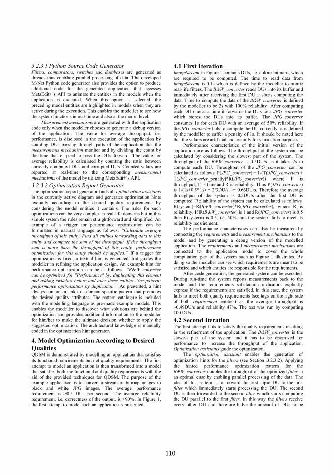
3.2.3.1 Python Source Code GeneratorFilters, comparators, switches and databases are generated asthreads thus enabling parallel processing of data. The developedM-Net Python code generator also provides the option to produceadditional code for the generated application that accessesMetaEdit+’s API to animate the entities in the models when theapplication is executed. When this option is selected, thepreceding model entities are highlighted in models when they areactive during the execution. This enables the modeller to see howthe system functions in real-time and also at the model level.
Measurement mechanisms are generated with the applicationcode only when the modeller chooses to generate a debug versionof the application. The value for average throughput, i.e.performance, is disclosed in the execution of the application bycounting DUs passing through parts of the application that themeasurements mechanism monitor and by dividing the count bythe time that elapsed to pass the DUs forward. The value foraverage reliability is calculated by counting the ratio betweencorrectly computed DUs and corrupted DUs. Counted values arereported at real-time to the corresponding measurementmechanisms of the model by utilizing MetaEdit+’s API.3.2.3.2 Optimization Report GeneratorThe optimization report generator finds all optimization assistantsin the currently active diagram and generates optimization hintstextually according to the desired quality requirements byconsidering the model entities it contains. The rules for suchoptimizations can be very complex in real-life domains but in thissimple system the rules remain straightforward and simplified. Anexample of a trigger for performance optimization can beformulated in natural language as follows: “Calculate averagethroughput of this entity. Find all entities forwarding data to thisentity and compute the sum of the throughput. If the throughputsum is more than the throughput of this entity, performanceoptimization for this entity should be applied.” If a trigger foroptimization is fired, a textual hint is generated that guides themodeller in refining the application design. An example hint forperformance optimization can be as follows: “B&W_convertercan be optimized for "Performance" by: duplicating this elementand adding switches before and after these entities. See pattern:performance optimization by duplication.” As presented, a hintalways contains a link to a domain-specific pattern that promotesthe desired quality attributes. The pattern catalogue is includedwith the modelling language as pre-made example models. Thisenables the modeller to discover what solutions are behind theoptimization and provides additional information to the modellerfor him/her to make the ultimate decision whether to apply thesuggested optimization. The architectural knowledge is manuallycoded in the optimization hint generator.
4. Model Optimization According to DesiredQualitiesQDSM is demonstrated by modelling an application that satisfiesits functional requirements but not quality requirements. The firstattempt to model an application is then transformed into a modelthat satisfies both the functional and quality requirements with theaid of the provided techniques for QDSM. The purpose of theexample application is to convert a stream of bitmap images toblack and white JPG images. The average performancerequirement is >0.5 DUs per second. The average reliabilityrequirement, i.e. correctness of the output, is >90%. In Figure 1,the first attempt to model such an application is presented.
4.1 First IterationImageStream in Figure 1 contains DUs, i.e. colour bitmaps, whichare required to be computed. The time to read data fromImageStream is 0.1s which is defined by the modeller to mimicreal-life filters. The B&W_converter reads DUs into its buffer andimmediately after receiving the first DU it starts computing thedata. Time to compute the data of the B&W_converter is definedby the modeller to be 2s with 100% reliability. After computingeach DU one at a time it forwards the DUs to a JPG_converterwhich stores the DUs into its buffer. The JPG_converterconsumes 1s for each DU with an average of 50% reliability. Ifthe JPG_converter fails to compute the DU correctly, it is definedby the modeller to suffer a penalty of 1s. It should be noted herethat the values are artificial and are only for simulation purposes.
Performance characteristics of the initial version of theapplication are as follows. The throughput of the system can becalculated by considering the slowest part of the system. Thethroughput of the B&W_converter is 0.5DU/s as it takes 2s tocompute each DU. Throughput of the JPG_converter can becalculated as follows. P(JPG_converter) = 1/(T(JPG_converter) +T(JPG_converter_penalty)*R(JPG_converter)) where P isthroughput, T is time and R is reliability. Thus P(JPG_converter)is 1/(1s+0.5*1s) = 2/3DU/s ~= 0.66DU/s. Therefore the averagethroughput of the system is 0.5DU/s after the first DU iscomputed. Reliability of the system can be calculated as follows.R(system)=R(B&W_converter)*R(JPG_converter), where R isreliability. If R(B&W_converter) is 1 and R(JPG_converter) is 0.5then R(system) is 0.5, i.e. 50% thus the system fails to meet itsreliability requirement.
The performance characteristics can also be measured byconnecting the requirements and measurement mechanisms to themodel and by generating a debug version of the modelledapplication. The requirements and measurement mechanisms areconnected to the application model to cover the wholecomputation part of the system such as Figure 1 illustrates. Bydoing so the modeller can see which requirements are meant to besatisfied and which entities are responsible for the requirements.
After code generation, the generated system can be executed.During run-time the system reports measurements back to themodel and the requirements satisfaction indicators explicitlyexpress if the requirements are satisfied. In this case, the systemfails to meet both quality requirements (see tags on the right sideof both requirement entities) as the average throughput is~0.49DU/s and reliability 47%. The test was run by computing100 DUs.4.2 Second IterationThe first attempt fails to satisfy the quality requirements resultingin the refinement of the application. The B&W_converter is theslowest part of the system and it has to be optimized forperformance to increase the throughput of the application.Optimization assistants guide the optimization.
The optimization assistant enables the generation ofoptimization hints for the filters (see Section 3.2.3.2). Applyingthe hinted performance optimization pattern for theB&W_converter doubles the throughput of the optimized filter inan optimal case by enabling parallel processing of the data. Theidea of this pattern is to forward the first input DU to the firstfilter which immediately starts processing the DU. The secondDU is then forwarded to the second filter which starts computingthe DU parallel to the first filter. In this way the filters receiveevery other DU and therefore halve the amount of DUs to be
110110

handled per filter. Thus, when the un-optimized B&W_converterproduces 0.5DU/s, the throughput of the optimized filtercombination is 1DU/s with 100% reliability. Now, the averagethroughput of the application is 0.66DU/s where theJPG_converter is the slowest part. The throughput requirementshould be now satisfied.
Reliability of the application is still unsatisfactory thereforethe JPG_converter has to be optimized for reliability. Theoptimization assistant produces the following hint for theJPG_converter: “The JPG_converter can be optimized for"Reliability" by: duplicating this element and inputting the samedata to both, and adding a comparator with the option "Errorfilter" after these elements. See pattern: reliability optimization byduplication.” The idea of this pattern is to compute the same datatwice and forward the result to a comparator that forwards thecorrupted DU only if both filters produce erroneous data.Otherwise the comparator forwards the first successfullycomputed DU. By applying this pattern the average reliability ofthe optimized filter increases, i.e. in this case reliability isincreased to 75%. Applying this pattern twice results in anaverage of ~94% reliability. Figure 2 represents the optimizedapplication model.
Figure 2. Application model that satisfies the requirements.In Figure 2, the application model that satisfies the both
quality requirements is modelled. As can be seen, the developedpattern recognition engine automatically identifies the utilizedpatterns by tagging the corresponding filters with the promotedquality attributes. On top of the B&W_converters there is a<<Performance>> tag which ensures that these two filtersparticipate in a pattern that promotes performance whereas in theJPG_converters there is <<Reliability>> tag. The tags should helpthe modeller to establish a design rationale for the application.
The calculated performance characteristics can be verified bygenerating an implementation from the model in debug mode andby executing the application. As requirements entities in Figure 2does not have the tags on the right side, the application nowsatisfies the requirements. The average throughput measured bycomputing 100DUs is 0.58DU/s where reliability is 94%.
5. DiscussionWe demonstrated QDSM with a laboratory-based case study of astream-oriented computing system. For the system, an M-NetDSML and a code generator that enables full Python codegeneration from models was developed with MetaCaseMetaEdit+. The most important means to support QDSM arebased on 1) a quality requirements definition in models, 2) an
automated model evaluation with pattern recognition, and 3)testing and reporting mechanisms.
Whereas a quality requirements definition technique isindependent of the domain, model evaluation and testing can beconsidered domain-specific. In different domains, testing ofexecution-time quality requirements are largely dependent onwhat is measured and how. In this manner reusing the presentedmechanisms between different domains is not possible. However,the concept remains. It is surprisingly useful to see the test resultsof an executed application also at the model-level. It is also usefulto explicitly discover what quality requirements are satisfied. Thisenables to easily find out what requirements are satisfied and whatparts of the model do not satisfy their quality requirements.
Design-time model evaluation for execution-time qualitieswas implemented in the laboratory case by identifying whatpatterns are utilized in the application model. As shown via thelaboratory case, tentative design rationale can be obtained byutilizing pattern recognition. The evaluation could, however, alsohave included prediction of the performance characteristics as wasdone manually in the examples to provide more explicit values forquality attributes. Although evolution-time qualities such asmodifiability and extensibility were not discussed in this paper,pattern recognition could also be utilized to provide someknowledge about the promoted evolution-time qualities. However,automation for quality evaluation except in the case of patternrecognition, which can provide tentative design rationale aboutthe promoted qualities, might be a challenge for evolution-timequalities since scenario-based evaluation methods still need neuralprocessing.
As discussed, it seems that pattern recognition can onlyprovide tentative design rationale from quality perspective. Thus,it is questionable whether pattern recognition is sufficient foridentifying the design rationale even in such a restricted area asDSM. In addition, different patterns promote different qualitiesand the utilized patterns might be overlapping in the applicationmodels. Therefore, finding out the design rationale by applyingpattern recognition is not straightforward. In addition, sometimesit is not patterns that promote different qualities but more likefunctional blocks that are responsible for affecting a certainquality attribute. For instance, decreasing image resolution inimage processing application certainly increases further imagemanipulation performance compared to utilizing high-resolutionimages. Decreasing image resolution might be a reason foroptimizing the performance but sometimes the only reason for thisis to satisfy a certain functional requirement.
As shown, by only identifying the utilized patterns it is notpossible to discover the performance characteristics. Only atentative design rationale can be obtained which, however, is stilluseful. Therefore to overcome the limitations with patternrecognition, next we will concentrate on manual approaches indescribing design rationale by connecting requirementsengineering side, where different techniques to affect the qualityand their interrelated dependencies and impact to qualities aredescribed, to the application development side. We already havedeveloped a technique with tool support to provide measuredperformance characteristics from application models torequirements engineering side in order to ease the quality analysisin requirements engineering [23]. Next, we will connect thedifferent design alternatives identified in requirementsengineering to application development in a way that the impactof the utilized design alternatives to quality is automaticallyshown in application models. Thus, we rather strive for semi-
111111
automated approach than automated as it seems that humanscannot really be replaced by computers, yet.6. ConclusionThere is a constant need for decreasing development costs insoftware development while at the same time increasing thequality of software applications. Increasing productivity can beachieved by utilizing MDD and especially DSM in softwaredevelopment. Nevertheless to increase the desired qualities ofapplications requires that not only the quality requirements mustbe considered at every development phase but that a continuouslink from quality requirements to application design, testing andrelease must also be maintained. Maintaining such a link is crucialto reveal whether all the requirements set for softwareapplications have been satisfied.
As the success of MDD extensively lies in the provided toolsupport, in this paper we demonstrated that there currently aremature integrated tooling environments, such as MetaCaseMetaEdit+, that can be utilized as a platform for quality-drivenDSM where the quality is traceable from quality requirements toapplication release. We demonstrated the tooling environmentwith a laboratory-conducted case study of a stream-orientedcomputing system.
7. ACKNOWLEDGMENTSThe work presented here has been developed within the MoSiSproject ITEA 2 – ip06035. MoSiS is a project within the ITEA 2 –Eureka framework.
8. REFERENCES[1] Selic, B. The Pragmatics of Model-Driven Development.
IEEE Computer Society. IEEE Software, 2003, pp. 19-25.[2] Kelly, S. and Tolvanen, J-P, Domain-Specific Modeling –
Enabling full code generation, John Wiley & Sons, NewJersey, 2008, 427p., ISBN: 978-0-470-03666-2.
[3] Niemelä, E., Kalaoja, J. and Lago, P. 2005. Toward anarchitectural knowledge base for wireless serviceengineering, IEEE Transactions on Software Engineering,Vol. 31, No. 5, pp. 361-379. ISSN 0098-5589.
[4] Chung, L., Gross, D. and Yu, E., Architectural design tomeet stakeholder requirements, The 1st Working IFIPConference on Software Architecture, Kluwer AcademicPublishers, San Antonio, TX, USA, 1999.
[5] Chung, L., Nixon, B.A., Yu, E. and Mylopoulus, J., Non-Functional Requirements in Software Engineering, KluwerAcademic Publishers, Boston, 2000.
[6] Kazman, R., Klein, M. and Clements, P., ATAM: Method forarchitecture evaluation, Carnegie Mellon University,Software Engineering Institute, Tech. Rep. CMU/SEI-2000-TR-004 ESC-TR-2000-004, 2000, 83 p.
[7] Tarvainen, P., Adaptability Evaluation at SoftwareArchitecture Level. The Open Software Engineering Journal,vol. 2, Bentham Science Publishers Ltd., 2008, pp. 1-30,ISSN: 1874-107X,http://www.bentham.org/open/tosej/openaccess2.htm
[8] Henttonen, K, Matinlassi, M., Niemelä, E., Kanstren, T.Integrability and Extensibility Evaluation from SoftwareArchitecture Models – A Case Study, 2007, Open SoftwareEngineering. Vol. 1 No. 1, pp.1-20.
[9] Bachmann, F., Bass, L., Klein, M., Moving from qualityattribute requirements to architectural decisions, In: SecondInternational Software Requirements to Architectures,STRAW’03, 2003, Portland, USA.
[10] Ebert, C., Putting requirement management into praxis:dealing with nonfunctional requirements, Information &Software Technology 40(3): 175-185, 1998.
[11] Evesti, A. 2007 Quality-oriented software architecturedevelopment, VTT Publications 636, VTT, Espoo, 2007,79p., URL:http://www.vtt.fi/inf/pdf/publications/2007/P636.pdf
[12] Merilinna, J., Niemelä, E., A stylebase as a tool formodelling of quality-driven software architecture, InProceedings of the Estonian Academy of SciencesEngineering. Special issue on Programming Languages andSoftware Tools., vol. 11, No. 4, 2005, pp. 296–312.
[13] Matinlassi, M. and Niemelä, E., The Impact ofMaintainability on Component-based Software Systems. In:29th Euromicro Conference (EUROMICRO’03), Turkey,2003, pp. 25-32.
[14] Carimo, R. A., Evaluation of UML Profile for Quality ofService from the User Perspective, Master’s Thesis, SoftwareEngineering, Thesis no: MSE-2007-03, August 2006.
[15] Etxeberria, L., Sagardui, G., Belategi, L., ModellingVariation in Quality Attributes, First International Workshopon Variability Modelling of Software-intensive SystemsLimerick, Ireland — January 16–18, 2007.
[16] Savolainen, P., Niemelä, E., Savola, R., A Taxonomy ofInformation Security for Service-Centric Systems,Proceedings of the 33rd EUROMICRO Conference onSoftware Engineering and Advanced Applications, 2007.
[17] Ernst N., Yu Y., Mylopoulos J., Visualizing non-functionalrequirements, In First International Workshop onRequirements Engineering Visualization (REV'06),Minneapolis, Minnesota, USA, 2006.
[18] Merilinna, J. and Räty, T., Bridging the Gap between theQuality Requirements and Implementation, The FourthInternational Conference on Software Engineering Advances(ICSEA 2009), September 20-25, 2009 - Porto, Portugal, 6p.
[19] Alexander, C., The Timeless Way of Building, OxfordUniversity Press, 1979.
[20] Lee, J. and Xue, N.L, Analyzing user requirements by usecases: A goal-driven approach. IEEE Software, 16 (4):92-101, July/August 1999.
[21] Fanjiang, Y-Y. and Kuo, J.Y., A Pattern-based ModelTransformation Approach to Enhance Design Quality, InProceedings of the 9th Joint Conference on InformationSciences (JCIS), 2006.
[22] StreamIt, Research overview page, URL:http://www.cag.lcs.mit.edu/streamit/shtml/research.shtml[Visited at 3.6.2009].
[23] Yrjönen, A. and Merilinna, J., Extending the NFRFramework with Measurable Non-Functional Requirements,2nd International Workshop on Non-functional SystemProperties in Domain Specific Modeling Languages, Denver,Colorado, USA, Oct 4-9, 2009.
112112

Towards a Generic Layout Composition Framework forDomain Specific Models
Jendrik Johannes∗
Technische Universität DresdenInstitut für Software- und Multimediatechnik
D-01062, Dresden, [email protected]
Karsten GaulTechnische Universität Dresden
Institut für Software- und MultimediatechnikD-01062, Dresden, [email protected]
ABSTRACTDomain Specific Models with graphical syntax play a bigrole in Model-Driven Software Development, as do modelcomposition tools. Those tools however, often ignore or de-stroy layout information which is vital for graphical models.We believe that one reason for the insufficient support forlayout information in model composition tools is the lackof generic solutions that are easy to adapt for new graph-ical modelling languages. Therefore, this paper proposesa language-independent framework for layout preservationand composition as an extension to existing model composi-tion frameworks. We describe the single components of theframework and evaluate it in combination with the Reuse-ware Composition Framework for layout compositions in twodifferent industrial used languages. We discuss the resultsof this evaluation and the next steps to be taken.
1. INTRODUCTIONIn Model-Driven Software Development (MDSD) differentgraphical Domain Specific Models defined in different Do-main Specific Modelling Languages (DSMLs) are used incombination. MDSD approaches promise high flexibilitywith regard to the DSMLs that are used and how theseare combined. Using metamodelling tools, developers cancreate new DSMLs when required and integrate them intotheir MDSD process by defining model transformations andcompositions. Different technologies are available for modeltransformation and composition which are language inde-pendent. That is, they can be used with any DSML that isdefined by a metamodel they understand.
A drawback of such language-independent approaches is thatthey handle the semantic models, but rarely support thepreservation and composition of layout information. This,however, is an important issue, because the outcome of amodel composition is seldom the final system which is (like acompiled piece of code) processed by machines, but anothermodel to be viewed and edited by developers. Thus, we ar-gue that layout preservation and composition is crucial forthe acceptance of MDSD. Currently, however, approachesthat are easy to adapt for new DSMLs are missing.
This paper proposes such an approach for compositions ofmodels within arbitrary graphical DSMLs (Section 2). It
∗This research has been co-funded by the European Com-mission in the 6th Framework Programme project Mod-elplex contract no. 034081 (www.modelplex.org).
provides an implementation of the approach in an extensi-ble framework that is based on the Eclipse Modeling Frame-work (EMF) [18]. Our framework can be used with arbitrarygraphical DSMLs defined in EMF’s metalanguage Ecore [18].It can be connected to arbitrary EMF-based model com-position engines that fulfill a number of properties we willdiscuss. One example of such an engine is the ReusewareComposition Framework [8] with which we evaluated ourapproach. We performed an evaluation of our frameworkwith two different DSMLs (Section 3) used in industry. Af-terwards, in Section 4, we discuss lessons learned and futureextensions to broaden the scope of our framework. We lookat related work in Section 5 and conclude in Section 6.
2. LAYOUT COMPOSITIONIn this section we introduce the concepts behind our frame-work and, based on that, the different components of it.First (Section 2.1), we specify the scope of our work bydefining criteria for the DSMLs and the model compositionframeworks we support. Second (Section 2.2), we introducethe Mental Map concept on which we base our approach.Third (Section 2.3), we describe the different steps of ourlayout preservation and composition process and show vari-ability within the different steps which can be implementedin individual components in our framework. Fourth (Sec-tion 2.4), we introduce the components we implemented.
2.1 Criteria for Supported DSMLs and ModelComposition Frameworks
A DSML has to fulfill the following properties to work withour approach:Requirement 1 The DSML has to have a graphical (dia-grammatical) syntax.1
Requirement 2 The DSML has to be defined in Ecore.2
The following is required of a model composition frameworkto interoperate with our layout composition framework.Requirement 3 The composition scripts for models haveto have a graphical (diagrammatical) syntax.1
Requirement 4 The composition framework needs to beable to expose which item in a composition script refers towhich input model.1
1Section 4 discusses how these restrictions can be loosened2This restriction applies if our implementation is reused di-rectly. Conceptually, our framework can be ported to an-other modelling environment.
113113
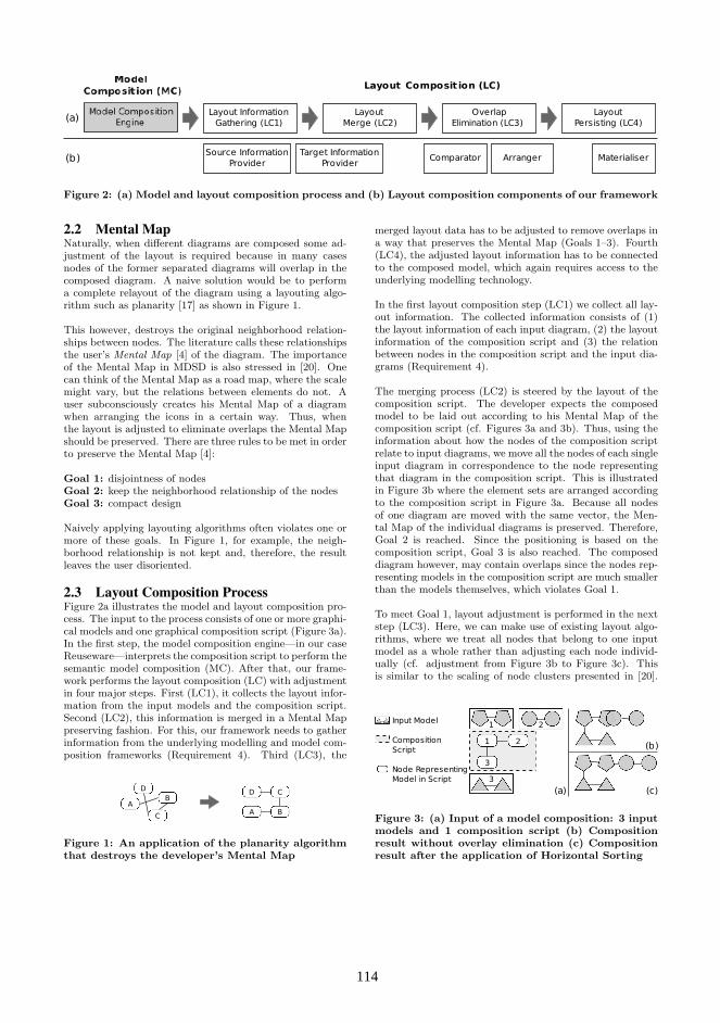
Layout Composit ion (LC)
Layout InformationGathering (LC1)
Overlap Elimination (LC3)
Layout Merge (LC2)
Layout Persisting (LC4)
Source InformationProvider
Target InformationProvider
Comparator Arranger Materialiser
(a)
(b)
Figure 2: (a) Model and layout composition process and (b) Layout composition components of our framework
2.2 Mental MapNaturally, when different diagrams are composed some ad-justment of the layout is required because in many casesnodes of the former separated diagrams will overlap in thecomposed diagram. A naive solution would be to performa complete relayout of the diagram using a layouting algo-rithm such as planarity [17] as shown in Figure 1.
This however, destroys the original neighborhood relation-ships between nodes. The literature calls these relationshipsthe user’s Mental Map [4] of the diagram. The importanceof the Mental Map in MDSD is also stressed in [20]. Onecan think of the Mental Map as a road map, where the scalemight vary, but the relations between elements do not. Auser subconsciously creates his Mental Map of a diagramwhen arranging the icons in a certain way. Thus, whenthe layout is adjusted to eliminate overlaps the Mental Mapshould be preserved. There are three rules to be met in orderto preserve the Mental Map [4]:
Goal 1: disjointness of nodesGoal 2: keep the neighborhood relationship of the nodesGoal 3: compact design
Naively applying layouting algorithms often violates one ormore of these goals. In Figure 1, for example, the neigh-borhood relationship is not kept and, therefore, the resultleaves the user disoriented.
2.3 Layout Composition ProcessFigure 2a illustrates the model and layout composition pro-cess. The input to the process consists of one or more graphi-cal models and one graphical composition script (Figure 3a).In the first step, the model composition engine—in our caseReuseware—interprets the composition script to perform thesemantic model composition (MC). After that, our frame-work performs the layout composition (LC) with adjustmentin four major steps. First (LC1), it collects the layout infor-mation from the input models and the composition script.Second (LC2), this information is merged in a Mental Mappreserving fashion. For this, our framework needs to gatherinformation from the underlying modelling and model com-position frameworks (Requirement 4). Third (LC3), the
D C
A B
D
C
AB
Figure 1: An application of the planarity algorithmthat destroys the developer’s Mental Map
merged layout data has to be adjusted to remove overlaps ina way that preserves the Mental Map (Goals 1–3). Fourth(LC4), the adjusted layout information has to be connectedto the composed model, which again requires access to theunderlying modelling technology.
In the first layout composition step (LC1) we collect all lay-out information. The collected information consists of (1)the layout information of each input diagram, (2) the layoutinformation of the composition script and (3) the relationbetween nodes in the composition script and the input dia-grams (Requirement 4).
The merging process (LC2) is steered by the layout of thecomposition script. The developer expects the composedmodel to be laid out according to his Mental Map of thecomposition script (cf. Figures 3a and 3b). Thus, using theinformation about how the nodes of the composition scriptrelate to input diagrams, we move all the nodes of each singleinput diagram in correspondence to the node representingthat diagram in the composition script. This is illustratedin Figure 3b where the element sets are arranged accordingto the composition script in Figure 3a. Because all nodesof one diagram are moved with the same vector, the Men-tal Map of the individual diagrams is preserved. Therefore,Goal 2 is reached. Since the positioning is based on thecomposition script, Goal 3 is also reached. The composeddiagram however, may contain overlaps since the nodes rep-resenting models in the composition script are much smallerthan the models themselves, which violates Goal 1.
To meet Goal 1, layout adjustment is performed in the nextstep (LC3). Here, we can make use of existing layout algo-rithms, where we treat all nodes that belong to one inputmodel as a whole rather than adjusting each node individ-ually (cf. adjustment from Figure 3b to Figure 3c). Thisis similar to the scaling of node clusters presented in [20].
Input Model
Composition Script
Node Representing Model in Script
(b)
(c)(a)
1 2
3
3
1 2
Figure 3: (a) Input of a model composition: 3 inputmodels and 1 composition script (b) Compositionresult without overlay elimination (c) Compositionresult after the application of Horizontal Sorting
114114

While a number of algorithms could be used (e.g., the onesdiscussed in [4]) we implement Horizontal Sorting [11] andUniform Scaling [4] so far. Horizontal Sorting, as its nameimplies, starts at the left side of the diagram and movesoverlapping fragments in x direction until they do not over-lap anymore (Figure 3c). Uniform Scaling is based on thefollowing equation: (a+s*(x-a), b+s*(y-b)). The point (a,b)is the center point and (x,y) is the location of the model el-ement set that needs to be moved. The factor s is a scalefactor used to define the distance the model elements aremoved by. For automatisation purposes, (a,b) should notbe chosen by the user—it can be computed from the mergeddiagram before adjustment (outcome of LC2, cf. Figure 3b).
In the last step (LC4) the computed layout information hasto be materialised in the diagram of the composed model.Here, access for modifying this diagram has to be providedby the modelling technology that was used.
2.4 Framework ComponentsThe previous section described the steps our layout com-position framework performs. These steps can be imple-mented in individual components, which could be exchangeddepending on specific demands of one composition. The dif-ferent components are illustrated in Figure 2b. In the follow-ing, we give details of the functionality of these componentsand present what we have implemented so far.
Different component combinations can be used to achievedifferent results. We summarize possible combinations atthe end of this section. In Section 3 we then evaluate whatthe benefits and drawbacks of certain combinations are.
2.4.1 Source Information Provider (LC1)An input model consists of an arbitrary number of nodesand, for a user friendly layout algorithm that obeys the rulesof the Mental Map, we have to know about the width andheight of these nodes. More precisely, width and height ofthe bounding box of the whole input model is needed (x andy values are not important here). An Information Providerwalks through the diagram structure and gathers the re-quired data. The Source Information Provider depends onthe layout format used for the input diagrams.
We implemented two Source Information Providers for twolayout formats commonly used in EMF, which are the GMFNotation Model [7] and the TOPCASED Diagram Inter-change format [19]. The GMF Notation Model is widelyspread, because it is used by all DSMLs created with theGMF—a generative DSML development framework. TOP-CASED is an alternative framework with similar functional-ity which currently offers a set of high quality UML editors.There are efforts to align both frameworks to obtain a com-mon layout format in the EMF (possibly aligned with an up-graded version of the Diagram Interchange OMG standard[15]). In general, the Information Providers implemented byus already cover a huge amount of diagram syntaxes used inEMF. Our experience showed that an Information Providercan be implemented within hours.
2.4.2 Target Information Provider (LC1 and LC2)Another Information Provider is required to obtain the lay-out information of the nodes in a composition script that
represent input models. We call this a Target InformationProvider because it determines the main structure of thecomposed diagram (cf. Figures 3a and 3b). It gathers the xand y values of the geometrical shapes that represent the in-put models in the graphical script. Height and width are notthat important here. This Information Provider depends onthe layout format used for composition scripts in the sup-ported composition engine.
In Reuseware, composition scripts (called composition pro-grams) are created in a graphical editor which was developedwith GMF. Consequently, we implemented one Target Infor-mation Provider that depends on the GMF Notation Modelfor layout information and on Reuseware to obtain the re-lationship information (Requirement 4) between nodes in acomposition script and input models.
2.4.3 Comparator (LC3)A Comparator ensures that layout composition is performedin a deterministic order. It is required when the semanticmodel composition does not depend on a deterministic order,but the layout adjustment does.
We implemented one Comparator that sorts input modelsaccording to their x position in the composition script (i.e.,the one given by the Target Information Provider). This isneeded for the Horizontal Sorting algorithm but was alsoused for the Uniform Scaling algorithm to have a determin-istic order (although any other deterministic Comparatorcould be used here).
2.4.4 Arranger (LC3)An Arranger does the actual layout adjustment if overlapsexist. Therefore, it first checks for overlaps and decides if ad-ditional adjustment is required. An Arranger could do thesesteps repetitively, depending on the adjustment algorithm.That is, if after one adjustment overlaps do still exist, it cando another algorithm run.
As mentioned in Section 2.3, we implement Horizontal Sort-ing and Uniform Scaling as two different Arrangers. De-pending on the concrete composition, both algorithms yieldresults of different quality, as we will discuss in Section 3.
2.4.5 Materialiser (LC4)The last step is materializing the computed layout in anactual diagram. This is realized by a Materialiser.
Materialisers also have to be implemented for each layoutformat that should be supported. Thus, we implementedone for GMF and one for TOPCASED.
In the next section we evaluate our framework in combina-tion with Reuseware using two graphical DSMLs, where oneis utilising GMF and one TOPCASED as layout format.For that, different combinations of the mentioned compo-nent implementations are used. We call such a combina-tion a layout composition strategy. The Source InformationProvider and the Materialiser are always determined by theformat used by the corresponding DSML. As Target Infor-mation Provider and Comparator we always use the onlyimplementation we provided so far. The Arrangers however
115115

Figure 4: (a) A CIM model (b) The same modelrepresented in a Reuseware composition script
can be varied (no Arranger, Horizontal Sorting, UniformScaling). We compare the different possible combinationsand discuss the results.
3. EVALUATIONIn this section we evaluate our layout composition frame-work on two different model compositions that were real-ized with the Reuseware Composition Framework in earlierworks: [8] in Section 3.1 and [10] in Section 3.2. We ap-ply different configurations of our layout composition frame-work and compare the results. Afterwards we discuss whatwe have achieved so far and what the next steps towards ageneric layout composition framework are in Section 4.
3.1 Common Information Model DSMLThe first model composition uses models from the telecomu-nications domain defined with a DSML that implements theCommon Information Model (CIM) standard [3]. A meta-model defined in Ecore and a graphical GMF-based editorfor the language were developed by Telefonica R&D andXactium in the MODELPLEX research project [5]. In thefollowing we concentrate on the layouting aspects of themodel compositions. More details of the semantic modelcomposition can be found in [10] and online1.
Figure 4 shows (a) the CIM model BuiltInEthernetHub inthe CIM GMF editor and (b) the representation of thatinput model in a composition script in Reuseware’s com-position script editor. The node in the composition scripthas different circles attached to it which are called Portsin Reuseware. Each Port points at a number of model el-ements in the input models that are modified during themodel composition. For more details please consult [8] andthe Reuseware website2.
CIM models are composed in different stages, where eachstage represents a different level of abstraction. The origi-nal input models (e.g., Figure 4a) developed with the men-tioned GMF editor reside on Level 1. A composition scriptthat composes these models defines a Level 2 composition.A composition script, that uses the results of Level 2 com-positions as input models is located on Level 3 and so on.
The BuiltInEthernetHub (Figure 4a) is a model of Level 1.To compose the network model EthernetIPInterface, acomposition script on Level 2 was created which is depicted
1http://reuseware.org/index.php/Abstract CIM DSLs2http://reuseware.org
Figure 5: (a) Composition script for the EthernetIP-
Interface model (b) Composed model
in Figure 5a. In addition to the BuiltInEthernetHub thescript contains the input models Core and IP. The Core isan empty model into which CIM model elements are com-posed. Thus, it holds no graphical representation and layoutinformation. The IP contains only one model element andconsequently one graphical node.
We execute the composition defined in Figure 5a with threedifferent layout composition strategies. Each strategy usesthe Source Information Provider and Materialiser developedfor GMF, the Target Information Provider that works forReuseware’s composition scripts and the Comparator. Thefirst strategy applies no layout adjustment, the second usesHorizontal Sorting and the third Uniform Scaling.
No layout adjustment Figure 5b shows the diagram thatresults from the composition of Figure 5a without layoutadjustment. We observe that the elements overlap (Goal 1)since the diagrams are bigger than the icons in the composi-tion script (Figure 5a). This destroys the positioning in thedeveloper’s Mental Map (Goal 2) and only Goal 3 is reached.
Horizontal Sorting In Figure 6a Horizontal Sorting is usedfor layout adjustment. We observe, that the overlap hasbeen removed. The overlapping nodes have been movedalong the x-axis. While Goal 1 is reached here, Goal 2 isnot completely satisfied. The IP model which is located be-low the BuiltInEthernetHub in Figure 5a is now located onthe right of it.
Uniform Scaling In Figure 6b we utilise Uniform Scaling(with a scale factor s=2). Here, the mental map is wellpreserved and all three Goals are satisfied.
Figure 6: Adjusted layout: (a) Horizontal Sorting(b) Uniform Scaling
116116

Figure 7: Level 3 composition script
We have seen that the layout adjustment is necessary evenfor a small model to avoid overlaps while preserving theMental Map. While Horizontal Sorting performs worse thanUniform Scaling concerning the exactness of neighborhoodrelations, it yields a more compact design. Thus, it couldstill be an acceptable option here.
A more complex composition is shown in Figure 7. It is aLevel 3 CIM abstraction that reuses results of earlier com-positions on Level 2 which are the EthernetIPInterface
from above as well as the models ADSLStaticIPInterface
and System. We apply two different layout strategies usingthe two different algorithms to examine how they behave forlarger models and how our framework behaves in a stagedmodel composition.
Figure 8a (Horizontal Sorting) and Figure 8b (Uniform Scal-ing) show the different composition results. In principle,the same observations as above can be made, but the men-tioned issues become more obvious. In the case of HorizontalSorting, everything is aligned along the x-axis, while it wasaligned along the y-axis in Figure 7. In the case of Uni-form Scaling, the problem of less compact design increases.Although we used only a small scale factor (s=2), the dia-gram is getting relatively large. This is due to the fact thatall element sets are moved uniformly in different directions,resulting into unused spaces between smaller element sets.
In Figures 8a and 8b we can also observe that a layout com-posed in an earlier step (i.e., the layout of EthernetIPInter-face which is composed by Figure 5a) is not modfied any-more. Thus, different strategies can be applied at differentstages of a composition. In Figures 8b, Horizontal Sortingwas applied to compose EthernetIPInterface which keeps
Figure 8: Composed Level 3 diagram: (a) HorizontalSorting (b) Uniform Scaling
Figure 9: A business process extension modelled asUML activity in TOPCASED [19]
the overall layout more compact compared to the case whereUniform Scaling is applied everywhere (not shown).
3.2 UML Activities for Business ProcessesBusiness processes as presented in [6] can be modelled asUML activity models. A core process can be extended withnew sub-processes by composing those models with Reuse-ware as we did in [8]. An example of a sub-process is shownin Figure 9. When it is composed into a larger core activity,the initial and final nodes (black circles) are replaced withother nodes in the core—integrating both activities.
We tested our layout composition framework with the mod-els of [8]. This time, we had to use the TOPCASED specificcomponents, since the diagrams were created with the TOP-CASED UML editor. The adjustment worked in the samemanner as for the CIM models confirming the results aboutstrength and weaknesses of the algorithms and demonstrat-ing that the framework can be used with other DSMLs.
4. NEXT STEPSThis section discusses the results of the last section andpoints out future work to improve our layout compositionframework. We have seen throughout the evaluation thatthere is not one best strategy for layout adjustment. Whichis the best strategy rather depends on many factors fromthe sizes of the input models up to the personal taste of thedeveloper and how he uses the DSML at hand. A possibil-ity is to make the developer aware of the different strategiesand let him experiment with different ones—as we did in theevaluation. However, if many compositions are defined, thisextra work of evaluating (and re-evaluating) all strategieseach time a composition or one of its input models changescan become a tedious task. It should be possible to selectstrategies automatically based on further analysis of the in-put models or by allowing the developer to specify criteriafor this selection. This requires analysis of a broader exam-ple space in the future.
Since we made certain assumptions about the models andthe model compositions when we decided how to preserve theMental Map, there are cases that are not so well supportedby our framework at the moment. Consider the UML activ-ity example (Figure 9). Here the nodes Start, Success andFailure are replaced by others during a composition. Cur-rently, the layout information about these replaced nodes isalways discarded. However, there are also examples whereit seems to be more intuitive to position the replacing nodeat the position of the replaced node—for instance, if onlyone node is inserted and not a whole diagram. This howeverhighly depends on the concrete kinds of compositions thatare performed. If and how the best strategy can be deter-mined automatically will have to be explored by evaluatingdifferent kinds of compositions. In addition, if a replacing
117117
node should take the position of the replaced node, the com-position framework needs to reveal the relationship betweensuch nodes (extension of Requirement 4).
Another thing we have not considered yet are diagrams thatdo not follow the simple node and edge paradigm but aremore restrictive (e.g., UML sequence charts). In such cases,the layout adjustment possibilities are limited on the onehand, but might also not be necessary on the other hand(because a “good” layout is enforced by the nature of thegraphical formalism). More investigations are required here.
A point that might hinder the combination with other modelcomposition engines is the requirement for a graphical com-position script (Requirement 3), since many such tools comewith textual specification languages. In principle, such lan-guages could also be handled by translating text positions(e.g., the order in which input models are referenced) intographical layout information (by a specific Target Informa-tion Provider). Consequently, to support a textual language,a useful translation has to be found.
5. RELATED WORKMany modelling tools do not pay proper attention to layoutinformation today. Graphical modelling tools and frame-works such as GMF [7], TOPCASED [19], Rational Soft-ware Architect [9], Borland Together [2], MagicDraw [13]or Fujaba [12] offer facilities which apply layout algorithmsto whole or partial diagrams. Despite the fact that thesealgorithms do not consider the Mental Map of the existinglayout and often fail to produce viable results for large di-agrams, the tools also do not offer facilities to preserve ortransfer layouts from one diagram to another. MDSD pro-cess tools such as openArchitectureWare [14] or AndroMDA[1] completely ignore layout information when composing ortransforming models.
Our work focuses on model compositions that are performedbetween models defined in one DSML. Another importantdiscipline is model transformation between different DSMLs.Here, layout information is also seldom handled and alsonot considered in standardization efforts such as QVT [16].Pilgrim et al. [20, 21] used trace links created during a modeltransformation to obtain layout information from the sourcediagram to layout the target diagram. They however do notdiscuss what the limitations for the model transformationare they support and only considered Uniform Scaling toremove overlaps so far.
6. CONCLUSIONWe presented a generic layout composition framework to im-prove layout preservation in MDSD. The architecture of theframework and the components we implemented were intro-duced and utilised in several examples. These experimentsshowed that the provided solutions are a great improvementover current practice. They also showed, however, weak-nesses and limitations of our work so far. Based on this, weidentified challenges as a base for further work to improvethe quality and genericity of the presented layout compo-sition framework. In the future, we will tackle these chal-lenges and perform more experiments on different DSMLswith distinct graphical syntaxes.
7. REFERENCES[1] AndroMDA Development Team. AndroMDA.
http://www.andromda.org/, 2009.
[2] Borland. Borland Together. http://www.borland.com/us/products/together/, 2009.
[3] Distributed Management Task Force Inc. (DMTF).Common Information Model Standards.http://www.dmtf.org/standards/cim/, 2008.
[4] P. Eades, W. Lai, K. Misue, and K. Sugiyama.Preserving the mental map of a diagram. ResearchReport IIAS-RR-91-16E, 1991.
[5] A. Evans, M. A. Fernandez, and P. Mohagheghi.Experiences of Developing a Network Modeling ToolUsing the Eclipse Environment. In Proc. ofECMDA-FA’09, volume 5562 of LNCS. Springer, 2009.
[6] M. Fritzsche, W. Gilani, C. Fritzsche, I. T. A. Spence,P. Kilpatrick, and T. J. Brown. Towards UtilizingModel-Driven Engineering of Composite Applicationsfor Business Performance Analysis. In Proc.ECMDA-FA’08, volume 5095 of LNCS. Springer, 2008.
[7] GMF Development Team. Graphical ModelingFramework. http://www.eclipse.org/gmf/, 2009.
[8] F. Heidenreich, J. Henriksson, J. Johannes, andS. Zschaler. On Language-Independent ModelModularisation. In Transactions on Aspect-OrientedDevelopment, LNCS. Springer, 2009. To Appear.
[9] IBM. Rational Software Architect. http://ibm.com/software/awdtools/architect/swarchitect/, 2009.
[10] J. Johannes, S. Zschaler, M. A. Fernandez, A. Castillo,D. S. Kolovos, and R. F. Paige. Abstracting ComplexLanguages through Transformation and Composition.In Proc. of MoDELS’09, LNCS. Springer, 2009.
[11] K. Misue, P. Eades, W. Lai, and K. Sugiyama. Layoutadjustment and the mental map. Research ReportISAS-RR-94-6E, 1991.
[12] U. Nickel, J. Niere, and A. Zundorf. The FUJABAEnvironment. In Proc. of ICSE’00. IEEE, 2000.
[13] No Magic, Inc. MagicDraw.http://www.magicdraw.com/, 2009.
[14] oAW Development Team. openArchitectureWare.http://www.openarchitectureware.org/, 2009.
[15] Object Management Group. Diagram InterchangeSpecification, v1.0, 2006.http://www.omg.org/cgi-bin/doc?formal/06-04-04.
[16] Object Management Group. Meta Object Facility(MOF) 2.0 Query/View/Transformation, 2008.http://www.omg.org/cgi-bin/doc?formal/08-04-03.
[17] R. C. Read. A New Method for Drawing a PlanarGraph Given the Cyclic Order of the Edges at EachVertex. Congressus Numerantium 56, 1987.
[18] D. Steinberg, F. Budinsky, M. Paternostro, andE. Merks. Eclipse Modeling Framework, 2nd Edition.Pearson Education, 2008.
[19] TOPCASED Development Team. TOPCASEDEnvironment. http://www.topcased.org, 2009.
[20] J. von Pilgrim. Mental Map and Model DrivenDevelopment. In Proc. of LED’07. EASST, 2007.
[21] J. von Pilgrim, B. Vanhooff, I. Schulz-Gerlach, andY. Berbers. Constructing and VisualizingTransformation Chains. In Proc. of ECMDA-FA’08,volume 5095 of LNCS. Springer, 2008.
118118

Model-Based Autosynthesis of Time-Triggered Buffers forEvent-Based Middleware Systems ∗
Jonathan SprinkleUniversity of Arizona
Brandon EamesUtah State University
ABSTRACTApplication developers utilizing event-based middleware havesought to leverage domain-specific modeling for the advan-tages of intuitive specification, code synthesis, and supportfor design evolution, among other benefits. For cyber-physicalsystems, the use of event-based middleware may result, forsome applications, in a need for additional time-based blocksthat were not initially considered during system design. Anadvantage of domain-specific modeling is the ability to refac-tor an application to include time-triggered, event-basedschedulers. In this paper we present an application in needof such modification, and discuss how these additional blocksmust be synthesized in order to conform to the input/outputconstraints of the existing diagram.
Categories and Subject DescriptorsD.2.6 [Software Engineering]: Prog. Environments—In-tegrated environments
KeywordsMetamodeling, software synthesis, graph rewriting
1. INTRODUCTIONCyber-physical systems involve algorithms and design tech-niques from the disciplines of control, real-time systems,robotics, software, communications, and many other appli-cation domains. Experience spanning multiple disciplines isrequired when developing these kinds of systems in order tomanage the various subtleties of each domain, in addition tothe subtleties of their integration.
In existing implementations of today’s cyber-physical sys-tems, designers commonly employ one of many discrete event-based computational models [25, 6, 11, 26]. In these mod-els, components execute based on the exchange of tokenswith other discrete event components. On execution, com-ponents acquire input tokens from their associated inputqueues, perform computation and submit their results to anyconsumers via output queues. A common event-based execu-tion approach is realized through the application of event-based middleware, where (potentially) distributed compo-nents communicate through message passing in order to ex-change data. The receipt of data typically triggers compo-nent execution.
∗This work supported by the Air Force Research Labs, un-der award #FA8750-08-1-0024, titled “MultiCore HardwareExperiments in Software Producibility.”
Generally, components for such systems are developed byalgorithm experts who understand well their computationalbehavior. Occasionally when a system is composed fromcomponents whose execution triggering rules are determinedin an ad hoc manner by each developer, the behavior ofthe system is emergent in nature, as opposed to being en-gineered by design. A more principled system design couldconsider the semantics of the composition of the components(as discussed in [7]). However, such integration is difficultto enforce in a programming styleguide since the semanticsare at a higher level.
In this paper, we discuss how to enforce a time-triggered,as opposed to purely event driven, behavior through the in-sertion of data buffers whose contents are read and releasedon the receipt of time-triggered tokens. We provide someexamples of how existing domain-specific models of event-based middleware can be rewritten in order to produce newcomponent graphs that now implement this kind of scalablebehavior.
2. BACKGROUND2.1 MiddlewareThe growth in the number of middleware technologies, andtheir widespread adoption in large scale system design isa testament to their utility in mitigating low-level program-ming complexity in distributed system development. CORBAoffers a middleware platform for supporting distributed com-puting. Real-Time Object Request Brokers (ORBS) [19]have been developed, e.g. TAO [22], which integrate op-erating system services and network protocols to offer pre-dictable quality of service, including real-time or near realtime response. TAO allows distributed applications to bespecified as a set of interacting components. The middlewareservices manage data communication between components,including marshalling and demarshalling, allowing compo-nents to be written location-unaware. A variety of compet-ing middleware technologies and platforms have been devel-oped for supporting component-based distributed comput-ing, including Ice [8], Enterprise Java Beans (EJB) [15], theMicrosoft Component Object Model (COM) [3] and .NETframework [17], and Java RMI [24].
A key goal with middleware is the development of Quality ofService guarantees (QoS) for supporting application execu-tion. Certain metrics are critical to distributed applicationdevelopment, e.g. bandwidth, latency and jitter. Differentstudies have been conducted to evaluate and improve the
119119

t0
t1
t2
t→ ∞
τe
ωc1
x1 y1c1
x1 y1c1
x1 y1c1
(a) Event-Based Execution, τe ≤ τx1
x1 y1c1
x1 y1c1
x1 y1c1
t0
t1
t2
t→ ∞
τe
ωc1
x1 y1c1
x1 y1c1
t3
t4
ωc1
τx1
(b) Timeout Execution, τe > τx1
Figure 1: Alternative execution of a component with timeout on a blocking read. (a) A token is received before, or at, thetimeout of the blocking read. (b) No token is received by time t1, so a timeout event occurs, and the output token is basedon the previous input to the component. Receipt of later events occurs as in (a).
ability of middleware to offer predictable quality of service[21, 20]
2.2 Publish/Subscribe MethodsPublish/Subscribe is a common model of communicationused for data interchange between components. A compo-nent c1 will subscribe to another component’s production ofa particular data value, using services offered by the middle-ware. Then, the middleware will ensure that all subscribersreceive the value once it is produced. This can be consideredto be closely related to the producer/consumer model, how-ever the producer/consumer model typically only involves asingle consumer for a given producer. The publish/subscribemodel offers explicit support for a controlled broadcast com-munication.
Several middleware technologies support variants of the pub-lish/subscribe communication model, including Ice [8] andDDS [16]. Further, different approaches for implementingthe model exist, including having the consumer task pollthe producer for data availability, or having the producerperform a remote invocation on the consumer when data isavailable.
2.3 Time-Triggered MethodsDifferent techniques and infrastructures have been devel-oped to support distributed/embedded computing which ex-ecutes cognizant of time. Giotto [9, 10] offers a frameworkfor capturing and executing time triggered software. Ap-plications are captured as a set of interacting tasks, eachof which is assigned to a mode with an associated execu-tion period. Scheduling and inter-task communications aremanaged by Giotto’s runtime infrastructure, called the E-machine.
Farcas et al. [5] have developed a component model to sup-port the development of distributed real time systems. Com-ponents are decoupled from the platform and from eachother, both temporally and functionally. The componentmodel is based on the logical execution time (LET) modelintroduced with Giotto. Auerbach et al. [1] describe a Java-based approach for scheduling real-time control tasks on aquad-rotor model helicopter by making use of exotasks andthe LET model to guarantee deterministic execution.
The Time Triggered Architecture (TTA) [12] and Time Trig-gered Protocol (TTP) [13] have been developed to supportthe time-based execution of components in hard real-timesystems. Components are allowed to access shared commu-nication hardware based only on the clock, rather than need.Design time scheduling determines a priori the allocation ofaccess windows to shared busses. The goal of time triggeredexecution is to isolate the impact of component or subsystemfailures on the system as a whole.
3. DOMAIN SEMANTICSThe domain of event-driven component-based systems pro-vides significant freedom in the implementation of executionsemantics. This freedom, in part, motivates the need to con-strain execution across implementation platforms.
Our purpose in this section is to underscore the seman-tic reasons for which components specified in our languagecould execute differently on machines with different networklatencies, or processing power. This understanding moti-vates why we undertake this transformation process, andadditionally provides the semantics necessary for the com-ponents which we synthesize using the model transforma-tions in the next section. We provide here several examples
120120
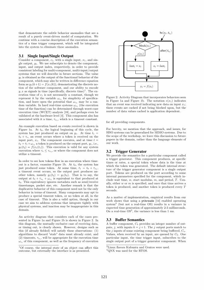
that demonstrate the subtle behavior anomalies that are aresult of a purely event-driven model of computation. Wecontinue with a concise description of the execution seman-tics of a time trigger component, which will be integratedinto the system to eliminate these anomalies.
3.1 Single Input/Single OutputConsider a component, c1, with a single input, x1, and sin-gle output, y1. We use subscripts to denote the component,input, and output index, respectively, in order to provideconsistent labeling for multi-component, multi-input/outputsystems that we will describe in future sections. The valuey1 is obtained as the output of the functional behavior of thecomponent, which may also be written in difference equationform as y1(k+1) = f(x1(k)), demonstrating the discrete no-tion of the software component, and our ability to encodey, x as signals in time (specifically, discrete time)1. The ex-ecution time of c1 is not necessarily a constant, though werepresent it by the variable ωc1 for simplicity of specifica-tion, and leave open the potential that ωc1 may be a ran-dom variable. In hard real-time systems ωc1 (the executiontime of the function) can be determined through worst-caseexecution time (WCET) analysis [18], and perhaps even bevalidated at the hardware level [4]. This component also hasassociated with it a time, τx1 , which is a timeout constant.
An example execution based on events received is shown inFigure 1a. At t0, the logical beginning of this cycle, thesystem has just produced an output on y1. At time t1 =t0 + τe, an event occurs where a token is received on theinput port, x1. The component executes, and at time t =t2 = t1 +ωc1 a token is produced on the output port, y1, i.e.,y1(t2) = f(x1(t1)). This execution is valid for any systemexecution where τe ≤ τx1 , or where the component does notutilize a timeout.
In order to see how tokens flow in an execution where time-out is a factor, examine Figure 1b. At t0, the system hasjust produced some token. At some time, t1 = t0 + τx1 ,a timeout event occurs, so the output port produces an-other token, namely y1(t2) = y1(t0). That is to say, theoutput at t0 + τx1 + ωc1 is equivalent to that produced att0. This equivalency ignores metadata such as send/receivetimestamps, packet size, etc. Another remark is that theduplicative behavior of this component need not be the onlybehavior in terms of timeout. Many components may opt toproduce a special timeout token, or no token at all, in thecase of timeout. This is also a valid option, though in ourcase we aim to address systems that integrate tightly withphysical systems, and inaction may be inappropriate in thisdomain.
An activity diagram that considers each of the cases pre-sented in Figure 1a and Figure 1b is shown in Figure 2. Inthis diagram, the mutually exclusive case of receiving data,or timing out, is clearly shown. However, designs such asthis (if already fielded) will satisfy these observations: (1)algorithms to discard “stale” data must already exist; and(2) timeouts, τxi , will be appropriate for the execution timeωci of this component, as well as the frequency of execution
1Of course, the internal state of an object can affect thisoutcome, but externally the interface is as presented.
after(!x1)e(x1)
last1 = x1 x1 = last1
y1 = f (x1)
block(x1)
bc(x1,!x1)
Figure 2: Activity Diagram that incorporates behaviors seenin Figure 1a and Figure 1b. The notation e(x1) indicatesthat an event was received indicating new data on input x1;these events are cached if not being blocked upon, but thenumber of data values cached is application dependent.
for all providing components.
For brevity, we mention that the approach, and issues, forSISO systems can be generalized for MIMO systems. Due tothe scope of the workshop, we leave this discussion to futurepapers in the domain, rather than the language elements ofour work.
3.2 Trigger GeneratorWe provide the semantics for a particular component calleda trigger generator. This component produces, at specifictimes or rates, a special token whose data is the time atwhich the token was generated. The default internal struc-ture of the trigger generator component is a single outputport. Tokens are produced on the port according to someinternal parameters specified for the component, which in-clude wait time, w, start modulus, m, and period, T . Usu-ally, either w or m is specified, and once that time arrives atoken is produced, and another token is produced every Tseconds.
As a matter of implementation, empirical results from ourwork shows that using a pthreads [14] enabled operatingsystem2 (but not a real-time OS) results in a variance inexpected time generation of approximately 2-3 milliseconds.On a real-time OS3, the variance is less than 1 ms.
3.3 Buffer SemanticsA buffer component, Cb provides an integer number of out-puts, j, with inputs k = j+ 1. The j output ports match tothe j inputs of some existing component being buffered, Ca.Values, when received by an input, are queued by Cb. Oneparticular input, the time trigger input, subscribes to thesingle output port of a trigger generator component. When
2Linux flavors Kubuntu and Gentoo were used.3QNX was used for the RTOS.
121121

a token is received on the time trigger port, the queued datavalues are sent to the output ports such that they can bereceived by Ca.
In future work, we may provide a special semantics for bufferswhere the most recent value received (only) on each inputport is passed to the output port. Our current semanticsrequires that if more than one value (or no value at all) isreceived by the buffer between triggers, then Ca is respon-sible for determining whether to use all, or only the mostrecent, values.
4. TRANSFORMATION AND EXAMPLEGiven the advantages of a system whose timing character-istics are explicitly expressed, we describe now a transfor-mation from a purely event-driven model to one with time-triggered execution. This transformation modifies an exist-ing graph, and permits existing components to execute withno behavioral changes: the only change to the system is thetopological rewrite, and the insertion of new buffered com-ponents along with their time-based triggers. Our method-ology is as follows: (1) examine an existing component inter-connection graph; (2) insert, before each component of thegraph, a time-triggered buffer; (3) insert, after each com-ponent of the graph, a time-triggered buffer; and (4) in-sert, somewhere in the graph, a timed event-generator foreach buffer, which sends events at the appropriate time Therewriting rules for this methodology are trivial, when speci-fied using the GReAT rewriting language [2]. In this section,we provide a subset of the transformations required.
4.1 Domain-specific Modeling LanguageOur systems are defined using a domain-specific language,capable of synthesizing experiments based on component in-terconnections. This work is explained thoroughly in [23].The metamodel is shown in Figure 3.
Figure 3: Relevant subset of the metamodel of our DSML(a screen capture from the GME tool).
Our system is built mainly of Component objects, connectedto one another through provided and required Interface
objects. The language provides several constraints (outsidethe scope of this paper) to prevent ill-formed models. We use
this metamodel as the source and destination metamodel inthe GReAT transformations.
4.2 Transformation RulesThe first task of the rewriting algorithm is to create newbuffer components, whose job it is to implement the seman-tics described in Section 3. The precise semantics are gen-erally decided for the entire graph, not piecemeal, and canbe a value selected when the graph transformation is exe-cuted. For brevity, we have provided an abbreviated algo-rithm, that only inserts buffers for the input of each graphcomponent. The algorithm to insert for component outputsis similar. An overall description of the rewrite is summa-rized by the rules shown in Figure 4.
NewBlockParadigm: UMLModelTransformer Project: Root Folder Model: Block Aspect: Transform Time: Fri Aug 07 05:53:11 PM
In Out
FindScenarioComponents
SceComIn
CreateBufferPorts
InSceComBuf
CreateInputBuffersIn
Figure 4: The order of rule execution for rewriting.
Buffers are added as Component objects, and the executablefor this object can be generically synthesized based on thenumber of input/output ports, and the semantics chosen.We leave this detailed discussion to future papers, and con-centrate instead on their insertion based on context. In Fig-ure 5 the rule details are shown.
The rule can be read as follows: for each Component thatcontains a RequiredInterface object, create a new Input-
Buffer:Component, with a RequiredInterface to accepttime triggers, that will become its input buffer. Create alsoa new Trigger:Component with a ProvidedInterface thatwill provide time triggered events, and connect that pro-vided port to the required trigger in the new buffer. Variousobjects are renamed for clarity in the final model.
We must also replace existing connections between two Com-
ponent objects by routing those connections between thenew InputBuffer:Compoment that we created above. A sim-ilar rule (not shown for brevity) removes the existing Con-
nection and creates two new ones, such that the Input-
Buffer:Component maps the data through to the Component.
Other rules not shown insert the necessary configurationitems for each trigger component, as discussed in Section 3.These include the frequency of execution (based on the WCETof the component), and the time modulus at which to startrunning.
Executing all of the rules gives the transformation resultshown in Figure 6.
5. ANALYSIS AND DISCUSSIONWhat role does Domain-Specific Modeling play in this appli-cation of transformations? In fact, why is modeling useful asa design concept here, rather than just using “old-fashioned”programming to solve the problem? What is the particularadvantage that model transformations give to enable thismigration from event-based to time-based behaviors?
122122

CreateInputBuffersParadigm: UMLModelTransformer Project: Root Folder Model: Rule Aspect: Transform Time: Sun Aug 09 03:45:37 PM
SetNamesIn
Buffer
Component
Scenario
RequiredSimulation::RequiredInterface
RequiredTriggerPortSimulation::RequiredInterface
InputBufferSimulation::Component
Platform : String="local"COMP_TAG : StringOrcaCall : StringEndpoints : String="tcp -t 5000"
ScenarioSimulation::Scenairo
Name : String
ComponentSimulation::Component
Platform : String="local"COMP_TAG : StringOrcaCall : StringEndpoints : String="tcp -t 5000"
TriggerSimulation::Component
Platform : String="local"COMP_TAG : StringOrcaCall : StringEndpoints : String="tcp -t 5000"
ProvidedTriggerSimulation::ProvidedInterface
Name : StringConnection
Simulation::Connection
dstConnection0..*
srcConnection0..*
Figure 5: GReAT rule to create buffer components for triggered input reading based on time-triggered events. Note that thetrigger scheduler is generated at the same step.
NewScenairoParadigm: Simulation Project: Root Folder Model: Scenairo Aspect: Model Time: Sun Aug 09 05:25:03 PM
Req
C3
Req Pro
C2ProPro
C1
(a) Original model.
NewScenairo
Paradigm: Simulation Project: Root Folder Model: Scenairo Aspect: Model Time: Sun Aug 09 05:23:43 PM
Req
C3InB
TimOut
C3IPBuf
Pro
Pro
C1
InB
TimOut
C2IPBuf
Pro
C2InputTrigger
Pro
C3InputTrigger
Req Pro
C2
(b) Transformed model.
Figure 6: (a) An original model, with only event-based triggering. (b) The result of transforming (a) with the rules discussedin Section 4.2.
With response to the relation to DSM, the application re-quires a domain-specific encoding of existing solution. Thelanguage we designed places particular emphasis on event-based behaviors, and the simple interfaces defined betweencomponents of production and consumption enable the di-rection of data to be well understood. Thus, such a lan-guage is able to capture existing systems, and run them [23].This is an important distinction: a design that concentratedmainly on how the new system, with its new semantics,should be represented would be unable to validate that anexisting model accurately represents the system as is.
So, why not use just clever programming techniques to mi-grate systems to the new semantics? Certainly this approachcould be taken, but at the usual risk of requiring experts inthe system design to become experts in new semantics, andnew techniques for execution. Our approach permits exist-ing system components to continue to work using their oldsemantics. Thus, not one line of code needs to be changed inthe existing software to conform to the new time-triggeredbehaviors.
Additionally, system experts know how their systems arecurrently organized, and implemented. These experts cantake our language and represent the models both as theyare, and (perhaps) as they should be in the future. Themodel transformation approach to creating the new buffers
is advantageous in that it reuses the investment in the en-coding of the system into our DSML.
The model transformation approach (through GReAT) reusesthe metamodel-based specification of the DSM in a way thatlanguage designers can discuss how types are used, and newcomponents are generated, with the system experts. Weagain point out that this permits reuse of existing code-bases. Approaches that do not use the strong typing andconstraint-based organization that DSMLs provide to theend user run the risk that some corner cases may not becovered, or that assumptions made by the migration soft-ware are invalid according to the metamodel.
6. CONCLUSION AND FUTURE WORKWe have described how event-driven component-based sys-tems can experience differences of execution based on subtletiming changes. We presented the notion of inserting time-triggered buffers as a way to reuse existing component code,while increasing the timing accuracy of component execu-tion. We showed how, with an existing DSML to modelsuch component-based systems, we can use model transfor-mation techniques to enforce our time-triggered semanticson an existing model. We provided a semantics for thesebuffers, as well as the time triggers that control how longbuffers hold their data tokens.
123123

Our future work includes various autogeneration of the buffercode for various component-based middleware frameworks.We can also become more sophisticated in the synthesis oftime trigger components, to attempt to consolidate the nec-essary scheduling into a single component, rather than a dis-tributed set of components, thus increasing the scalability ofthe system without increasing the number of components inthe system linearly.
AcknowledgmentsThis work is supported by the Air Force Research Labo-ratory, under award #FA8750-08-1-0024, titled “MultiCoreHardware Experiments in Software Producibility.”
7. REFERENCES[1] J. Auerbach, D. F. Bacon, D. T. Iercan, C. M. Kirsch,
V. T. Rajan, H. Roeck, and R. Trummer. Java takesflight: time-portable real-time programming withexotasks. SIGPLAN Not., 42(7):51–62, 2007.
[2] D. Balasubramanian, A. Narayanan, C. van Buskirk,and G. Karsai. The graph rewriting andtransformation language: GReAT. ElectronicCommunications of the EASST, 1, 2006.
[3] D. Box. Essential COM. Addison-Wesley, Reading,MA, 1997.
[4] A. Colin and I. Puaut. Worst case execution timeanalysis for a processor with branch prediction.Real-Time Systems, 18(2-3):249–274, May 2000.
[5] E. Farcas, C. Farcas, W. Pree, and J. Templ.Transparent distribution of real-time componentsbased on logical execution time. In LCTES ’05:Proceedings of the 2005 ACM SIGPLAN/SIGBEDconference on Languages, compilers, and tools forembedded systems, pages 31–39, New York, NY, USA,2005. ACM.
[6] G.Kahn. The semantics of a simple language forparallel programming. In Proceedings of the IFIPCongress. North-Holland Publishing Co., 1974.
[7] A. Goderis, C. Brooks, I. Altintas, E. A. Lee, andC. Goble. Heterogeneous composition of models ofcomputation. Technical Report UCB/EECS-2007-139,EECS Department, University of California, Berkeley,Nov 2007.
[8] M. Henning and M. Spruiell. Distributed Programmingwith Ice. 3.3.1b edition, July 2009.
[9] T. Henzinger, B. Horowitz, and C. Kirsch. Giotto: atime-triggered language for embedded programming.Proceedings of the IEEE, 91(1):84–99, Jan 2003.
[10] T. A. Henzinger, C. M. Kirsch, and S. Matic.Composable code generation for distributed Giotto.SIGPLAN Not., 40(7):21–30, 2005.
[11] G. Kahn and D. B. MacQueen. Coroutines andnetworks of parallel processes. Information Processing,1977.
[12] H. Kopetz and G. Bauer. The time-triggeredarchitecture. Proceedings of the IEEE, Special Issue onModeling and Design of Embedded Software, Oct. 2001.
[13] H. Kopetz and G. Grunsteidl. Ttp - a time-triggeredprotocol for fault-tolerant real-time systems. InProceedings of The Twenty-Third InternationalSymposium on Fault-Tolderant Computing, volumeFTCS-23, 1993.
[14] B. Lewis and D. J. Berg. Multithreaded ProgrammingWith PThreads. Prentice Hall PTR, 1997.
[15] R. Monson-Haefel. Enterprise JavaBeans. O’Reilly,3rd edition, 2001.
[16] Object Modeling Group. Data Distribution Service forReal-Time Systems, Version 1.2, formal/07-01-01edition, January 2007.
[17] J. Prosise. Programming Microsoft .NET. MicrosoftPress, June 15 2002.
[18] P. Puschner and C. Koza. Calculating the maximum,execution time of real-time programs. Real-Time Syst.,1(2):159–176, 1989.
[19] I. Pyarali, C. O’Ryan, D. Schmidt, N. Wang,A. Gokhale, and V. Kachroo. Using principle patternsto optimize real-time ORBs. Concurrency, IEEE,8(1):16–25, Jan-Mar 2000.
[20] I. Pyarali, D. Schmidt, and R. Cytron. Techniques forenhancing real-time CORBA quality of service.Proceedings of the IEEE, 91(7):1070–1085, July 2003.
[21] R. E. Schantz, J. P. Loyall, D. C. Schmidt,C. Rodrigues, Y. Kirishnamurthy, and I. Pyarali.Flexible and adaptive QoS control for distributedreal-time and embedded middleware. In Proceedings ofMiddleware 2003, Rio de Janeiro, Brazil, June 16-202003. 4th IFIP/ACM/USENIX InternationalConference on Distrubted Systems Platforms.
[22] D. Schmidt, D. Levine, and S. Mungee. The designand performance of real-time object request brokers.Computer Communications, April 1998.
[23] A. Schuster and J. Sprinkle. Synthesizing executablesimulations from structural models ofcomponent-based systems. In 3rd InternationalWorkshop on Multi-Paradigm Modeling, October 2009.
[24] A. Wollrath, R. Riggs, and J. Waldo. A distributedobject model for the java system. USENIX ComputingSystems, MIT Press, 9(4), Nov/Dec 1996.
[25] K. Wong and C. Wang. Push-Pull Messaging: ahigh-performance communication mechanism forcommodity SMP clusters. In Parallel Processing,1999. Proceedings. 1999 International Conference on,pages 12–19, 1999.
[26] B. Zeigler, H. Praehofer, and T. Kim. Theory ofmodeling and simulation. Academic Press, 2000.
124124

HELSINGIN KAUPPAKORKEAKOULUN JULKAISUJAPublications of the Helsinki School of Economics
A-SARJA: VÄITÖSKIRJOJA - DOCTORAL DISSERTATIONS. ISSN 1237-556X.
A:287. TImO JÄRVENSIVU: Values-driven management in strategic networks: A case study of the influence of organizational values on cooperation. 2007.
ISBN-10: 952-488-081-4, ISBN-13: 978-952-488-081-7.
A:288. PETRI HILLI: Riskinhallinta yksityisen sektorin työeläkkeiden rahoituksessa. 2007. ISBN-10: 952-488-085-7, ISBN-13: 978-952-488-085-5.
E-version: ISBN 978-952-488-110-4.
A:289. ULLA KRUHSE-LEHTONEN: Empirical Studies on the Returns to Education in Finland. 2007. ISBN 978-952-488-089-3, E-version ISBN 978-952-488-091-6.
A:290. IRJA HyVÄRI: Project management Effectiveness in Different Organizational Conditions. 2007. ISBN 978-952-488-092-3, E-version: 978-952-488-093-0.
A:291. mIKKO mÄKINEN: Essays on Stock Option Schemes and CEO Compensation. 2007. ISBN 978-952-488-095-4.
A:292. JAAKKO ASPARA: Emergence and Translations of management Interests in Corporate Branding in the Finnish Pulp and Paper Corporations. A Study with an Actor-Network Theory Approach. 2007. ISBN 978-952-488-096-1, E-version: 978-952-488-107-4.
A:293. SAmI J. SARPOLA: Information Systems in Buyer-supplier Collaboration. 2007. ISBN 978-952-488-098-5.
A:294. SANNA K. LAUKKANEN: On the Integrative Role of Information Systems in Organizations: Observations and a Proposal for Assessment in the Broader Context of Integrative Devices. 2006. ISBN 978-952-488-099-2.
A:295. CHUNyANG HUANG: Essays on Corporate Governance Issues in China. 2007. ISBN 978-952-488-106-7, E-version: 978-952-488-125-8.
A:296. ALEKSI HORSTI: Essays on Electronic Business models and Their Evaluation. 2007. ISBN 978-952-488-117-3, E-version: 978-952-488-118-0.
A:297. SARI STENFORS: Strategy tools and strategy toys: management tools in strategy work. 2007. ISBN 978-952-488-120-3, E-version: 978-952-488-130-2.
A:298. PÄIVI KARHUNEN: Field-Level Change in Institutional Transformation: Strategic Responses to Post-Socialism in St. Petersburg Hotel Enterprises. 2007.
ISBN 978-952-488-122-7, E-version: 978-952-488-123-4.
A:299. EEVA-KATRI AHOLA: Producing Experience in marketplace Encounters: A Study of Consumption Experiences in Art Exhibitions and Trade Fairs. 2007.
ISBN 978-952-488-126-5.
A:300. HANNU HÄNNINEN: Negotiated Risks: The Estonia Accident and the Stream of Bow Visor Failures in the Baltic Ferry Traffic. 2007. ISBN 978-952-499-127-2.
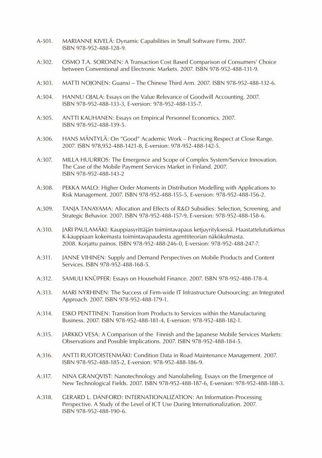
A-301. mARIANNE KIVELÄ: Dynamic Capabilities in Small Software Firms. 2007. ISBN 978-952-488-128-9.
A:302. OSmO T.A. SORONEN: A Transaction Cost Based Comparison of Consumers’ Choice between Conventional and Electronic markets. 2007. ISBN 978-952-488-131-9.
A:303. mATTI NOJONEN: Guanxi – The Chinese Third Arm. 2007. ISBN 978-952-488-132-6.
A:304. HANNU OJALA: Essays on the Value Relevance of Goodwill Accounting. 2007. ISBN 978-952-488-133-3, E-version: 978-952-488-135-7.
A:305. ANTTI KAUHANEN: Essays on Empirical Personnel Economics. 2007. ISBN 978-952-488-139-5.
A:306. HANS mÄNTyLÄ: On ”Good” Academic Work – Practicing Respect at Close Range. 2007. ISBN 978,952-488-1421-8, E-version: 978-952-488-142-5.
A:307. mILLA HUURROS: The Emergence and Scope of Complex System/Service Innovation. The Case of the mobile Payment Services market in Finland. 2007.
ISBN 978-952-488-143-2
A:308. PEKKA mALO: Higher Order moments in Distribution modelling with Applications to Risk management. 2007. ISBN 978-952-488-155-5, E-version: 978-952-488-156-2.
A:309. TANJA TANAyAmA: Allocation and Effects of R&D Subsidies: Selection, Screening, and Strategic Behavior. 2007. ISBN 978-952-488-157-9, E-version: 978-952-488-158-6.
A:310. JARI PAULAmÄKI: Kauppiasyrittäjän toimintavapaus ketjuyrityksessä. Haastattelututkimus K-kauppiaan kokemasta toimintavapaudesta agenttiteorian näkökulmasta.
2008. Korjattu painos. ISBN 978-952-488-246-0, E-version: 978-952-488-247-7.
A:311. JANNE VIHINEN: Supply and Demand Perspectives on mobile Products and Content Services. ISBN 978-952-488-168-5.
A:312. SAmULI KNüPFER: Essays on Household Finance. 2007. ISBN 978-952-488-178-4.
A:313. mARI NyRHINEN: The Success of Firm-wide IT Infrastructure Outsourcing: an Integrated Approach. 2007. ISBN 978-952-488-179-1.
A:314. ESKO PENTTINEN: Transition from Products to Services within the manufacturing Business. 2007. ISBN 978-952-488-181-4, E-version: 978-952-488-182-1.
A:315. JARKKO VESA: A Comparison of the Finnish and the Japanese mobile Services markets: Observations and Possible Implications. 2007. ISBN 978-952-488-184-5.
A:316. ANTTI RUOTOISTENmÄKI: Condition Data in Road maintenance management. 2007. ISBN 978-952-488-185-2, E-version: 978-952-488-186-9.
A:317. NINA GRANqVIST: Nanotechnology and Nanolabeling. Essays on the Emergence of New Technological Fields. 2007. ISBN 978-952-488-187-6, E-version: 978-952-488-188-3.
A:318. GERARD L. DANFORD: INTERNATIONALIZATION: An Information-Processing Perspective. A Study of the Level of ICT Use During Internationalization. 2007.
ISBN 978-952-488-190-6.

A:319. TIINA RITVALA: Actors and Institutions in the Emergence of a New Field: A Study of the Cholesterol-Lowering Functional Foods market. 2007. ISBN 978-952-488-195-1.
A:320. JUHA LAAKSONEN: managing Radical Business Innovations. A Study of Internal Corporate Venturing at Sonera Corporation. 2007.
ISBN 978-952-488-201-9, E-version: 978-952-488-202-6.
A:321. BRETT FIFIELD: A Project Network: An Approach to Creating Emergent Business. 2008. ISBN 978-952-488-206-4, E-version: 978-952-488-207-1.
A:322. ANTTI NURmI: Essays on management of Complex Information Systems Development Projects. 2008. ISBN 978-952-488-226-2.
A:323. SAmI RELANDER: Towards Approximate Reasoning on New Software Product Company Success Potential Estimation. A Design Science Based Fuzzy Logic Expert System.
2008. ISBN 978-952-488-227-9.
A:324. SEPPO KINKKI: Essays on minority Protection and Dividend Policy. 2008. ISBN 978-952-488-229-3.
A:325. TEEmU mOILANEN: Network Brand management: Study of Competencies of Place Branding Ski Destinations. 2008. ISBN 978-952-488-236-1.
A:326. JyRKI ALI-yRKKÖ: Essays on the Impacts of Technology Development and R&D Subsidies. 2008. ISBN 978-952-488-237-8.
A:327. mARKUS m. mÄKELÄ: Essays on software product development. A Strategic management viewpoint. 2008. ISBN 978-952-488-238-5.
A:328. SAmI NAPARI: Essays on the gender wage gap in Finland. 2008. ISBN 978-952-488-243-9.
A:329. PAULA KIVImAA: The innovation effects of environmental policies. Linking policies, companies and innovations in the Nordic pulp and paper industry. 2008. ISBN 978-952-488-244-6.
A:330. HELI VIRTA: Essays on Institutions and the Other Deep Determinants of Economic Development. 2008. ISBN 978-952-488-267-5.
A:331. JUKKA RUOTINEN: Essays in trade in services difficulties and possibilities. 2008. ISBN 978-952-488-271-2, E-version: ISBN 978-952-488-272-9.
A:332. IIKKA KORHONEN: Essays on commitment and government debt structure. 2008. ISBN 978-952-488-273-6, E-version: ISBN 978-952-488-274-3.
A:333. mARKO mERISAVO: The interaction between digital marketing communication and customer loyalty. 2008. ISBN 978-952-488-277-4, E-version 978-952-488-278-1.
A:334. PETRI ESKELINEN: Reference point based decision support tools for interactive multiobjective optimization. 2008. ISBN 978-952-488-282-8.
A:335. SARI yLI-KAUHALUOmA: Working on technology: a study on collaborative R&D work in industrial chemistry. 2008. ISBN 978-952-488-284-2

A:336. JANI KILPI: Sourcing of availability services - case aircraft component support. 2008. ISBN 978-952-488-284-2, 978-952-488-286-6 (e-version).
A:337. HEIDI SILVENNOINEN: Essays on household time allocation decisions in a collective household model. 2008. ISBN 978-952-488-290-3, ISBN 978-952-488-291-0 (e-version).
A:338. JUKKA PARTANEN: Pk-yrityksen verkostokyvykkyydet ja nopea kasvu - case: Tiede- ja teknologiavetoiset yritykset. 2008. ISBN 978-952-488-295-8.
A:339. PETRUS KAUTTO: Who holds the reins in Integrated Product Policy? An individual company as a target of regulation and as a policy maker. 2008. ISBN 978-952-488-300-9, 978-952-488-301-6 (e-version).
A:340. KATJA AHONIEmI: modeling and Forecasting Implied Volatility. 2009. ISBN 978-952-488-303-0, E-version: 978-952-488-304-7.
A:341. mATTI SARVImÄKI: Essays on migration. 2009. ISBN 978-952-488-305-4, 978-952-488-306-1 (e-version).
A:342. LEENA KERKELÄ: Essays on Globalization – Policies in Trade, Development, Resources and Climate Change. 2009. ISBN 978-952-488-307-8, E-version: 978-952-488-308-5.
A:343. ANNELI NORDBERG: Pienyrityksen dynaaminen kyvykkyys - Empiirinen tutkimus graafisen alan pienpainoyrityksistä. 2009. ISBN 978-952-488-318-4.
A:344. KATRI KARJALAINEN: Challenges of Purchasing Centralization – Empirical Evidence from Public Procurement. 2009. ISBN 978-952-488-322-1, E-version: 978-952-488-323-8.
A:345. JOUNI H. LEINONEN: Organizational Learning in High-Velocity markets. Case Study in The mobile Communications Industry. 2009. ISBN 978-952-488-325-2.
A:346. JOHANNA VESTERINEN: Equity markets and Firm Innovation in Interaction. - A Study of a Telecommunications Firm in Radical Industry Transformation. 2009. ISBN 978-952-488-327-6.
A:347. JARI HUIKKU: Post-Completion Auditing of Capital Investments and Organizational Learning. 2009. ISBN 978-952-488-334-4, E-version: 978-952-488-335-1.
A:348. TANJA KIRJAVAINEN: Essays on the Efficiency of Schools and Student Achievement. 2009. ISBN 978-952-488-336-8, E-version: 978-952-488-337-5.
A:349. ANTTI PIRJETÄ: Evaluation of Executive Stock Options in Continuous and Discrete Time. 2009. ISBN 978-952-488-338-2, E-version: 978-952-488-339-9.
A:350. OLLI KAUPPI: A model of Imperfect Dynamic Competition in the Nordic Power market. 2009. ISBN 978-952-488-340-5, E-version: 978-952-488-341-2.
A:351. TUIJA NIKKO: Dialogic Construction of Understanding in Cross-border Corporate meetings. 2009. ISBN 978-952-488-342-9, E-version: 978-952-488-343-6.
A:352. mIKKO KORIA: Investigating Innovation in Projects: Issues for International Development Cooperation. 2009. ISBN 978-952-488-344-3, E-version: 978-952-488-345-0.
A:353. mINNA mUSTONEN: Strategiaviestinnän vastaanottokäytännöt - Henkilöstö strategia-viestinnän yleisönä. 2009. ISBN 978-952-488-348-1, E-versio: 978-952-488-349-8.
A:354. mIRELLA LÄHTEENmÄKI: Henkilötietojen hyödyntäminen markkinoinnissa kuluttajien tulkitsemana. Diskurssianalyyttinen tutkimus kuluttajan tietosuojasta. 2009.
ISBN 978-952-488-351-1, E-versio: 978-952-488-352-8.
A:355. ARNO KOURULA: Company Engagement with Nongovernmental Organizations from a Corporate Responsibility Perspective. 2009. ISBN 978-952-488-353-5, E-version: 978-952-488-354-2.
A:356. mIKA WESTERLUND: managing Networked Business models: Essays in the Software Industry. 2009. ISBN 978-952-488-363-4
A:357. RISTO RAJALA: Determinants of Business model Performance in Software Firms. 2009. ISBN 978-952-488-369-6. E-version: 978-952-488-370-2.
B-SARJA: TUTKImUKSIA - RESEARCH REPORTS. ISSN 0356-889X.
B:77. mATTI KAUTTO – ARTO LINDBLOm – LASSE mITRONEN: Kaupan liiketoiminta-osaaminen. 2007. ISBN 978-952-488-109-8.
B:78. NIILO HOmE: Kauppiasyrittäjyys. Empiirinen tutkimus K-ruokakauppiaiden yrittäjyysasenteista. Entrepreneurial Orientation of Grocery Retailers – A Summary.
ISBN 978-952-488-113-5, E-versio: ISBN 978-952-488-114-2.
B:79. PÄIVI KARHUNEN – OLENA LESyK – KRISTO OVASKA: Ukraina suomalaisyritysten toimintaympäristönä. 2007. ISBN 978-952-488-150-0, E-versio: 978-952-488-151-7.
B:80. mARIA NOKKONEN: Näkemyksiä pörssiyhtiöiden hallitusten sukupuolikiintiöistä. Retorinen diskurssianalyysi Helsingin Sanomien verkkokeskusteluista. Nasta-projekti.
2007. ISBN 978-952-488-166-1, E-versio: 978-952-488-167-8.
B:81. PIIA HELISTE – RIITTA KOSONEN – mARJA mATTILA: Suomalaisyritykset Baltiassa tänään ja huomenna: Liiketoimintanormien ja -käytäntöjen kehityksestä.
2007. ISBN 978-952-488-177-7, E-versio: 978-952-488-183-8.
B:82. OLGA mASHKINA – PIIA HELISTE – RIITTA KOSONEN: The Emerging mortgage market in Russia: An Overview with Local and Foreign Perspectives. 2007.
ISBN 978-952-488-193-7, E-version: 978-952-488-194-4.
B:83. PIIA HELISTE – mARJA mATTILA – KRZySZTOF STACHOWIAK: Puola suomalais-yritysten toimintaympäristönä. 2007. ISBN 978-952-488-198-2, E-versio: 978-952-488-199-9.
B:84. PÄIVI KARHUNEN – RIITTA KOSONEN – JOHANNA LOGRéN – KRISTO OVASKA: Suomalaisyritysten strategiat Venäjän muuttuvassa liiketoimintaympäristössä. 2008. ISBN 978-953-488-212-5, E-versio: 978-952-488-241-5.
B:85. mARJA mATTILA – EEVA KEROLA – RIITTA KOSONEN: Unkari suomalaisyritysten toimintaympäristönä. 2008. ISBN 978-952-488-213-2, E-versio: 978-952-488-222-4.
B:86. KRISTIINA KORHONEN – ANU PENTTILÄ – mAyUmI SHImIZU – EEVA KEROLA – RIITTA KOSONEN: Intia suomalaisyritysten toimintaympäristönä.2008. ISBN 978-952-488-214-9, E-versio: 978-952-488-283-5

B:87. SINIKKA VANHALA – SINIKKA PESONEN: Työstä nauttien. SEFE:en kuuluvien nais- ja miesjohtajien näkemyksiä työstään ja urastaan. 2008. ISBN 978-952-488-224-8, E-versio: 978-952-488-225-5.
B:88. POLINA HEININEN – OLGA mASHKINA – PÄIVI KARHUNEN – RIITTA KOSONEN: Leningradin lääni yritysten toimintaympäristönä: pk-sektorin näkökulma. 2008.
ISBN 978-952-488-231-6, E-versio: 978-952-488-235-4.
B:89. Ольга Машкина – Полина Хейнинен: Влияние государственного сектора на развитие малого и среднего предпринимательства в Ленинградской области: взгляд предприятий.2008. ISBN 978-952-488-233-0, E-version: 978-952-488-240-8.
B:90. mAI ANTTILA – ARTO RAJALA (Editors): Fishing with business nets – keeping thoughts on the horizon Professor Kristian möller. 2008. ISBN 978-952-488-249-1, E-version: 978-952-488-250-7.
B:91. RENé DE KOSTER – WERNER DELFmANN (Editors): Recent developments in supply chain management. 2008. ISBN 978-952-488-251-4, E-version: 978-952-488-252-1.
B:92. KATARIINA RASILAINEN: Valta orkesterissa. Narratiivinen tutkimus soittajien kokemuksista ja näkemyksistä. 2008. ISBN 978-952-488-254-5, E-versio: 978-952-488-256-9.
B:93. SUSANNA KANTELINEN: Opiskelen, siis koen. Kohti kokevan subjektin tunnistavaa korkeakoulututkimusta. 2008. ISBN 978-952-488-257-6, E-versio: 978-952-488-258.
B:94. KATRI KARJALAINEN – TUOmO KIVIOJA – SANNA PELLAVA: yhteishankintojen kustannusvaikutus. Valtion hankintatoimen kustannussäästöjen selvittäminen. 2008.
ISBN 978-952-488-263-7, E-versio: ISBN 978-952-488-264-4.
B:95. ESKO PENTTINEN: Electronic Invoicing Initiatives in Finland and in the European Union – Taking the Steps towards the Real-Time Economy. 2008.
ISBN 978-952-488-268-2, E-versio: ISBN 978-952-488-270-5.
B:96. LIISA UUSITALO (Editor): museum and visual art markets. 2008. ISBN 978-952-488-287-3, E-version: ISBN 978-952-488-288-0.
B:97. EEVA-LIISA LEHTONEN: Pohjoismaiden ensimmäinen kauppatieteiden tohtori Vilho Paavo Nurmilahti 1899-1943. 2008. ISBN 978-952-488-292-7,
E-versio: ISBN 978-952-488-293-4.
B:98. ERJA KETTUNEN – JyRI LINTUNEN – WEI LU – RIITTA KOSONEN: Suomalaisyritysten strategiat Kiinan muuttuvassa toimintaympäristössä. 2008 ISBN 978-952-488-234-7, E-versio: ISBN 978-952-488-297-2.
B:99. SUSANNA VIRKKULA – EEVA-KATRI AHOLA – JOHANNA mOISANDER – JAAKKO ASPARA – HENRIKKI TIKKANEN: messut kuluttajia osallistavan markkinakulttuurin fasilitaattorina: messukokemuksen rakentuminen Venemessuilla. 2008. ISBN 978-952-488-298-9, E-versio: ISBN 978-952-488-299-6.
B:100. PEER HULL KRISTENSEN – KARI LILJA (Eds): New modes of Globalization: Experimentalist Forms of Economics Organization and Enabling Welfare Institutions – Lessons from The Nordic Countries and Slovenia. 2009. ISBN 978-952-488-309-2, E-version: 978-952-488-310-8.

B:101. VIRPI SERITA – ERIK PÖNTISKOSKI (eds.) SEPPO mALLENIUS – VESA LEIKOS – KATARIINA VILLBERG – TUUA RINNE – NINA yPPÄRILÄ – SUSANNA HURmE: marketing Finnish Design in Japan. 2009. ISBN 978-952-488-320-7. E-version: ISBN 978-952-488-321-4.
B:102. POLINA HEININEN – OLLI-mATTI mIKKOLA – PÄIVI KARHUNEN – RIITTA KOSONEN:yritysrahoitusmarkkinoiden kehitys Venäjällä. Pk-yritysten tilanne Pietarissa. 2009.ISBN 978-952-488-329-0. E-version: ISBN 978-952-488-331-3.
B:103. ARTO LAHTI: Liiketoimintaosaamisen ja yrittäjyyden pioneeri Suomessa. 2009. ISBN 978-952-488-330-6.
B:104. KEIJO RÄSÄNEN: Tutkija kirjoittaa - esseitä kirjoittamisesta ja kirjoittajista akateemisessa työssä. 2009. ISBN 978-952-488-332-0. E-versio: ISBN 978-952-488-333-7.
B:105. TImO EKLUND – PETRI JÄRVIKUONA – TUOmAS mÄKELÄ – PÄIVI KARHUNEN: Kazakstan suomalaisyritysten toimintaympäristönä. 2009. ISBN 978-952-488-355-9.
B:106. ARTO LINDBLOm – RAmI OLKKONEN – VILJA mÄKELÄ (TOIm.): Liiketoimintamallit, innovaatiotoiminta ja yritysten yhteistyön luonne kaupan arvoketjussa.2009. ISBN 978-952-488-356-6. E-versio: ISBN 978-952-488-357-3.
B:107. mIKA GABRIELSSON – ANNA SALONEN – PAULA KILPINEN – mARKUS PAUKKU – TERHI VAPOLA – JODy WREN – LAURA ILONEN – KATRIINA JUNTUNEN: Respon-ding to Globalization: Strategies and management for Competitiveness. Final Report of a TEKES-project 1.8.2006-30.4.2009. 2009. ISBN 978-952-488-362-7.
B:108. mATTI ROSSI – JONATHAN SPRINKLE – JEFF GRAy – JUHA-PEKKA TOLVANEN (EDS.) Proceedings of the 9th OOPSLA Workshop on Domain-Specific modeling (DSm’09).
2009. ISBN 978-952-488-371-9. E--version: ISBN 978-952-488-372-6.
B:109. LEENA LOUHIALA-SALmINEN – ANNE KANKAANRANTA (Editors): The Ascent of International Business Communication. 2009. ISBN 978-952-488-373-3.
N-SARJA: HELSINKI SCHOOL OF ECONOmICS. mIKKELI BUSINESS CAmPUS PUBLICATIONS.ISSN 1458-5383
N:63. SOILE mUSTONEN – ANNE GUSTAFSSON-PESONEN: Oppilaitosten yrittäjyys-koulutuksen kehittämishanke 2004–2006 Etelä-Savon alueella. Tavoitteiden, toimen- piteiden ja vaikuttavuuden arviointi. 2007. ISBN: 978-952-488-086-2.
N:64. JOHANNA LOGRéN – VESA KOKKONEN: Pietarissa toteutettujen yrittäjäkoulutus-ohjelmien vaikuttavuus. 2007. ISBN 978-952-488-111-1.
N:65. VESA KOKKONEN: Kehity esimiehenä – koulutusohjelman vaikuttavuus. 2007. ISBN 978-952-488-116-6.
N:66. VESA KOKKONEN – JOHANNA LOGRéN: Kaupallisten avustajien – koulutusohjelman vaikuttavuus. 2007. ISBN 978-952-488-116-6.
N:67. mARKKU VIRTANEN: Summary and Declaration. Of the Conference on Public Support Systems of SmE’s in Russia and Other North European Countries. may 18 – 19, 2006, mikkeli, Finland. 2007. ISBN 978-952-488-140-1.

N:68. ALEKSANDER PANFILO – PÄIVI KARHUNEN: Pietarin ja Leningradin läänin potentiaali kaakkoissuomalaisille metallialan yrityksille. 2007. ISBN 978-952-488-163-0.
N:69. ALEKSANDER PANFILO – PÄIVI KARHUNEN – VISA mIETTINEN: Pietarin innovaatio-järjestelmä jayhteistyöpotentiaali suomalaisille innovaatiotoimijoille. 2007.
ISBN 978-952-488-164-7.
N:70. VESA KOKKONEN: Perusta Oma yritys – koulutusohjelman vaikuttavuus. 2007. ISBN 978-952-488-165-4.
N:71. JARI HANDELBERG – mIKKO SAARIKIVI: Tutkimus miktech yrityshautomon yritysten näkemyksistä ja kokemuksista hautomon toiminnasta ja sen edelleen kehittämisestä. 2007. ISBN 978-952-488-175-3.
N:72. SINIKKA myNTTINEN – mIKKO SAARIKIVI – ERKKI HÄmÄLÄINEN: mikkelin Seudun yrityspalvelujen henkilökunnan sekä alueen yrittäjien näkemykset ja suhtautuminen mentorointiin. 2007. ISBN 978-952-488-176-0.
N:73. SINIKKA myNTTINEN: Katsaus K-päivittäistavarakauppaan ja sen merkitykseen Itä-Suomessa. 2007. ISBN 978-952-488-196-8.
N:74. mIKKO SAARIKIVI: Pk-yritysten kansainvälistymisen sopimukset. 2008. ISBN 978-952-488-210-1.
N:75. LAURA TUUTTI: Uutta naisjohtajuutta Delfoi Akatemiasta – hankkeen vaikuttavuus. 2008. ISBN 978-952-488-211-8.
N:76. LAURA KEHUSmAA – JUSSI KÄmÄ – ANNE GUSTAFSSON-PESONEN (ohjaaja): StuNet -Business Possibilities and Education - hankkeen arviointi.
2008. ISBN 978-952-488-215-6.
N:77. PÄIVI KARHUNEN – ERJA KETTUNEN – VISA mIETTINEN – TIINAmARI SIVONEN: Determinants of knowledge-intensive entrepreneurship in Southeast Finland and Northwest Russia. 2008. ISBN 978-952-488-223-1.
N:78. ALEKSANDER PANFILO – PÄIVI KARHUNEN – VISA mIETTINEN: Suomalais-venäläisen innovaatioyhteistyön haasteet toimijanäkökulmasta. 2008. ISBN 978-952-488-232-3.
N:79. VESA KOKKONEN: Kasva yrittäjäksi – koulutusohjelman vaikuttavuus. 2008. ISBN 978-952-488-248-4.
N:80. VESA KOKKONEN: Johtamisen taidot - hankkeessa järjestettyjen koulutusohjelmien vaikuttavuus. 2008. ISBN 978-952-488-259-0.
N:81. mIKKO SAARIKIVI: Raportti suomalaisten ja brittiläisten pk-yritysten yhteistyön kehittämisestä uusiutuvan energian sektorilla. 2008. ISBN 978-952-488-260-6.
N:82. mIKKO SAARIKIVI – JARI HANDELBERG – TImO HOLmBERG – ARI mATILAINEN: Selvitys lujitemuovikomposiittituotteiden mahdollisuuksista rakennusteollisuudessa. 2008. ISBN 978-952-488-262-0.
N:83. PÄIVI KARHUNEN – SVETLANA LEDyAEVA – ANNE GUSTAFSSON-PESONEN – ELENA mOCHNIKOVA – DmITRy VASILENKO: Russian students’ perceptions of
entrepreneurship. Results of a survey in three St. Petersburg universities. Entrepreneurship development –project 2. 2008. ISBN 978-952-488-280-4.
N:84. PIIA NIKULA – ANU PENTTILÄ – OTTO KUPI – JUHANA URmAS – KIRSI KOmmONEN: Sirpaleisuudesta kilpailukyvyn keskiöön Asiantuntijoiden näkemyksiä luovien alojen kansainvälistymisestä. 2009. ISBN 978-952-488-346-7.
N:85 JUHANA URmAS – OTTO KUPI – PIIA NIKULA – ANU PENTTILÄ – KIRSI KOmmONEN: ” Kannattaa ottaa pienikin siivu” – Luovien alojen yritysten näkemyksiä kansainvälistymisestä. 2009. ISBN 978-952-488-347-4.
W-SARJA: TyÖPAPEREITA - WORKING PAPERS . ISSN 1235-5674. ELECTRONIC WORKING PAPERS, ISSN 1795-1828.
W:412. LOTHAR THIELE – KAISA mIETTINEN – PEKKA J. KORHONEN – JULIAN mOLINA: A Preference-Based Interactive Evolutionary Algorithm for multiobjective Optimization.
2007. ISBN 978-952-488-094-7.
W:413. JAN-ERIK ANTIPIN – JANI LUOTO: Are There Asymmetric Price Responses in the Euro Area? 2007. ISBN 978-952-488-097-8.
W:414. SAmI SARPOLA: Evaluation Framework for VmL Systems. 2007. ISBN 978-952-488-097-8.
W:415. SAmI SARPOLA: Focus of Information Systems in Collaborative Supply Chain Relationships. 2007. ISBN 978-952-488-101-2.
W:416. SANNA LAUKKANEN: Information Systems as Integrative Infrastructures. Information Integration and the Broader Context of Integrative and Coordinative Devices. 2007. ISBN 978-952-488-102-9.
W:417. SAmULI SKURNIK – DANIEL PASTERNACK: Uusi näkökulma 1900-luvun alun murroskauteen ja talouden murrosvaiheiden dynamiikkaan. Liikemies moses Skurnik osakesijoittajana ja -välittäjänä. 2007. ISBN 978-952-488-104-3.
W:418. JOHANNA LOGRéN – PIIA HELISTE: Kymenlaakson pienten ja keskisuurten yritysten Venäjä-yhteistyöpotentiaali. 2001. ISBN 978-952-488-112-8.
W:419. SARI STENFORS – LEENA TANNER: Evaluating Strategy Tools through Activity Lens. 2007. ISBN 978-952-488-120-3.
W:420. RAImO LOVIO: Suomalaisten monikansallisten yritysten kotimaisen sidoksen heikkeneminen 2000-luvulla. 2007. ISBN 978-952-488-121-0.
W:421. PEKKA J. KORHONEN – PyRy-ANTTI SIITARI: A Dimensional Decomposition Approach to Identifying Efficient Units in Large-Scale DEA models. 2007. ISBN 978-952-488-124-1.
W:422. IRyNA yEVSEyEVA – KAISA mIETTINEN – PEKKA SALmINEN – RISTO LAHDELmA: SmAA-Classification - A New method for Nominal Classification. 2007.
ISBN 978-952-488-129-6.
W:423. ELINA HILTUNEN: The Futures Window – A medium for Presenting Visual Weak Signals to Trigger Employees’ Futures Thinking in Organizations. 2007.
ISBN 978-952-488-134-0.

W:424. TOmI SEPPÄLÄ – ANTTI RUOTOISTENmÄKI – FRIDTJOF THOmAS: Optimal Selection and Routing of Road Surface measurements. 2007. ISBN 978-952-488-137-1.
W:425. ANTTI RUOTOISTENmÄKI: Road maintenance management System. A Simplified Approach. 2007. ISBN 978-952-488-1389-8.
W:426. ANTTI PIRJETÄ – VESA PUTTONEN: Style migration in the European markets 2007. ISBN 978-952-488-145-6.
W:427. mARKKU KALLIO – ANTTI PIRJETÄ: Incentive Option Valuation under Imperfect market and Risky Private Endowment. 2007. ISBN 978-952-488-146-3.
W:428. ANTTI PIRJETÄ – SEPPO IKÄHEImO – VESA PUTTONEN: Semiparametric Risk Preferences Implied by Executive Stock Options. 2007. ISBN 978-952-488-147-0.
W:429. OLLI-PEKKA KAUPPILA: Towards a Network model of Ambidexterity. 2007. ISBN 978-952-488-148-7.
W:430. TIINA RITVALA – BIRGIT KLEymANN: Scientists as midwives to Cluster Emergence. An Interpretative Case Study of Functional Foods. 2007. ISBN 978-952-488-149-4.
W:431. JUKKA ALA-mUTKA: Johtamiskyvykkyyden mittaaminen kasvuyrityksissä. 2007. ISBN 978-952-488-153-1.
W:432. mARIANO LUqUE – FRANCISCO RUIZ – KAISA mIETTINEN: GLIDE – General Formulation for Interactive multiobjective Optimization. 2007. ISBN 978-952-488-154-8.
W:433. SEPPO KINKKI: minority Protection and Information Content of Dividends in Finland. 2007. ISBN 978-952-488-170-8.
W:434. TAPIO LAAKSO: Characteristics of the Process Supersede Characteristics of the Debtor Explaining Failure to Recover by Legal Reorganization Proceedings.
2007. ISBN 978-952-488-171-5.
W:435. mINNA HALmE: Something Good for Everyone? Investigation of Three Corporate Responsibility Approaches. 2007. ISBN 978-952-488-189.
W:436. ARTO LAHTI: Globalization, International Trade, Entrepreneurship and Dynamic Theory of Economics.The Nordic Resource Based View. Part One. 2007. ISBN 978-952-488-191-3.
W:437. ARTO LAHTI: Globalization, International Trade, Entrepreneurship and Dynamic Theory of Economics.The Nordic Resource Based View. Part Two. 2007
ISBN 978-952-488-192-0.
W:438. JANI KILPI: Valuation of Rotable Spare Parts. 2007. ISBN 978-952-488-197-5.
W:439. PETRI ESKELINEN – KAISA mIETTINEN – KATHRIN KLAmROTH – JUSSI HAKANEN: Interactive Learning-oriented Decision Support Tool for Nonlinear multiobjective
Optimization: Pareto Navigator. 2007. ISBN 978-952-488-200-2.
W:440. KALyANmOy DEB – KAISA mIETTINEN – SHAmIK CHAUDHURI: Estimating Nadir Objective Vector: Hybrid of Evolutionary and Local Search. 2008. ISBN 978-952-488-209-5.

W:441. ARTO LAHTI: Globalisaatio haastaa pohjoismaisen palkkatalousmallin. Onko löydettä-vissä uusia aktiivisia toimintamalleja, joissa Suomi olisi edelleen globalisaation voittaja?
2008. ISBN 978-952-488-216-3.
W:442. ARTO LAHTI: Semanttinen Web – tulevaisuuden internet. yrittäjien uudet liiketoiminta-mahdollisuudet. 2008. ISBN 978-952-488-217-0.
W:443. ARTO LAHTI: Ohjelmistoteollisuuden globaali kasvustrategia ja immateriaalioikeudet. 2008. ISBN 978-952-488-218-7.
W:444. ARTO LAHTI: yrittäjän oikeusvarmuus globaalisaation ja byrokratisoitumisen pyörteissä. Onko löydettävissä uusia ja aktiivisia toimintamalleja yrittäjien syrjäytymisen estämiseksi?
2008. ISBN 978-952-488-219-4.
W:445. PETRI ESKELINEN: Objective trade-off rate information in interactive multiobjective optimization methods – A survey of theory and applications. 2008. ISBN 978-952-488-220-0.
W:446. DEREK C. JONES – PANU KALmI: Trust, inequality and the size of co-operative sector – Cross-country evidence. 2008. ISBN 978-951-488-221-7.
W:447. KRISTIINA KORHONEN – RIITTA KOSONEN – TIINAmARI SIVONEN – PASI SAUKKONEN: Pohjoiskarjalaisten pienten ja keskisuurten yritysten Venäjä-yhteistyöpotentiaali ja tukitarpeet. 2008. ISBN 978-952-488-228-6.
W:448. TImO JÄRVENSIVU – KRISTIAN mÖLLER: metatheory of Network management: A Contingency Perspective. 2008. ISBN 978-952-488-231-6.
W:449. PEKKA KORHONEN: Setting “condition of order preservation” requirements for the priority vector estimate in AHP is not justified. 2008. ISBN 978-952-488-242-2.
W:450. LASSE NIEmI – HANNU OJALA – TOmI SEPPÄLÄ: misvaluation of takeover targets and auditor quality. 2008. ISBN 978-952-488-255-2.
W:451. JAN-ERIK ANTIPIN – JANI LUOTO: Forecasting performance of the small-scale hybrid New Keynesian model. 2008. ISBN 978-952-488-261-3.
W:452. mARKO mERISAVO: The Interaction between Digital marketing Communication and Customer Loyalty. 2008. ISBN 978-952-488-266-8.
W:453. PETRI ESKELINEN – KAISA mIETTINEN: Trade-off Analysis Tool with Applicability Study for Interactive Nonlinear multiobjective Optimization. 2008. ISBN 978-952-488-269-9.
W:454. SEPPO IKÄHEImO – VESA PUTTONEN – TUOmAS RATILAINEN: Antitakeover provisions and performance – Evidence from the Nordic countries. 2008. ISBN 978-952-488-275-0.
W:455. JAN-ERIK ANTIPIN: Dynamics of inflation responses to monetary policy in the EmU area. 2008. ISBN 978-952-488-276-7.
W:456. KIRSI KOmmONEN: Narratives on Chinese colour culture in business contexts. The yin yang Wu Xing of Chinese values. 2008. ISBN 978-952-488-279-8.
W:457. mARKKU ANTTONEN – mIKA KUISmA – mINNA HALmE – PETRUS KAUTTO: materiaalitehokkuuden palveluista ympäristömyötäistä liiketoimintaa (mASCO2). 2008.
ISBN 978-952-488-279-8.

W:458. PANU KALmI – DEREK C. JONES – ANTTI KAUHANEN: Econometric case studies: overview and evidence from recent finnish studies. 2008. ISBN 978-952-488-289-7.
W:459. PETRI JyLHÄ – mATTI SUOmINEN – JUSSI-PEKKA LyyTINEN: Arbitrage Capital and Currency Carry Trade Returns. 2008. ISBN 978-952-488-294-1.
W:460. OLLI-mATTI mIKKOLA – KATIA BLOIGU – PÄIVI KARHUNEN: Venäjä-osaamisen luonne ja merkitys kansainvälisissä suomalaisyrityksissä. 2009. ISBN 978-952-488-302-3.
W:461. ANTTI KAUHANEN – SATU ROPONEN: Productivity Dispersion: A Case in the Finnish Retail Trade. 2009. ISBN 978-952-488-311-5.
W:462. JARI HUIKKU: Design of a Post-Completion Auditing System for Organizational Learning. 2009. ISBN 978-952-488-312-2.
W:463. PyRy-ANTTI SIITARI: Identifying Efficient Units in Large-Scale Dea models Using Efficient Frontier Approximation. 2009. ISBN 978-952-488-313-9.
W:464. mARKKU KALLIO – mERJA HALmE: Conditions for Loss Averse and Gain Seeking Consumer Price Behavior. 2009. ISBN 978-952-488-314-6.
W:465. mERJA HALmE – OUTI SOmERVUORI: Study of Internet material Use in Education in Finland. 2009. ISBN 978-952-488-315-3.
W:466. RAImO LOVIO: Näkökulmia innovaatiotoiminnan ja –politiikan muutoksiin 2000-luvulla. 2009. ISBN 978-952-488-316-0.
W:467. mERJA HALmE – OUTI SOmERVUORI: Revisiting Demand Reactions to Price Changes. 2009. ISBN 978-952-488-317-7.
W:468. SAmULI SKURNIK: SSJS Strategiabarometri – kehitystyö ja nykyvaihe. 2009. ISBN 978-952-488-319-1.
W:469. TOm RAILIO: A Brief Description of The Transdisciplinary Jurionomics and The Scandinavian Institutional Sources of Law Framework. 2009. ISBN 978-952-488-324-5.
W:470. KALyANmOy DEB – KAISA mIETTINEN – SHAmIK CHAUDHURI: An Estimation of Nadir Objective Vector Using a Hybrid Evolutionary-Cum-Local-Search Procedure. 2009. ISBN 978-952-488-326-9.
W:471. JENNI AHONEN – mARI ANTTONEN – ANTTI HEIKKINEN – JANI HÄTÄLÄ – JASmI LEHTOLA – LAURI NURmILAUKAS – TEEmU PELTOKALLIO – ANNINA PIEKKARI – mARJO REEN – SEBASTIAN SmART: Doing Business in Hungary. 2009.
ISBN 978-952-488-350-4.
W:472. mIKA WESTERLUND: The role of Network Governance in Business model Performance. 2009. ISBN 978-952-488-361-0.
W:473. DmITRy FILATOV – SINIKKA PARVIAINEN – PÄIVI KARHUNEN: The St. Petersburg Insurance market: Current Challenges and Future Opportunities. 2009.
ISBN 978-952-488-365-8.
W:474. mARKKU KALLIO – mERJA HALmE: Redefining Loss Averse and Gain Seeking Consumer Price Behavior Based on Demand Response. 2009. ISBN 978-952-488-366-5.

W:475. JOHANNA BRAGGE – TUURE TUUNANEN – PENTTI mARTTIIN: Inviting Lead Users from Virtual Communities to Co-create Innovative IS Services in a Structured Groupware Environment. 2009. ISBN 978-952-488-367-2.
W:476. RISTO RAJALA: Antecedents to and Performance Effects of Software Firms’ Business models. 2009. ISBN 978-952-488-368-9.
Z-SARJA: HELSINKI SCHOOL OF ECONOmICS.CENTRE FOR INTERNATIONAL BUSINESS RESEARCH. CIBR WORKING PAPERS. ISSN 1235-3931.
Z:16. PETER GABRIELSSON – mIKA GABRIELSSON: marketing Strategies for Global Expansion in the ICT Field. 2007. ISBN 978-952-488-105-0.
Z:17. mIKA GABRIELSSON – JARmO ERONEN – JORmA PIETALA: Internationalization and Globalization as a Spatial Process. 2007. ISBN 978-952-488-136-4.

Kaikkia Helsingin kauppakorkeakoulun julkaisusarjassa ilmestyneitä julkaisuja voi tilata osoitteella:
Ky-Palvelu Oy Helsingin kauppakorkeakouluKirjakauppa JulkaisutoimittajaRuneberginkatu 14-16 PL 121000100 Helsinki 00101 HelsinkiPuh. (09) 4313 8310, fax (09) 495 617 Puh. (09) 4313 8579, fax (09) 4313 8305Sähköposti: [email protected] Sähköposti: [email protected]
All the publications can be ordered from
Helsinki School of EconomicsPublications officerP.O.Box 1210FIN-00101 HelsinkiPhone +358-9-4313 8579, fax +358-9-4313 8305 E-mail: [email protected]


![Pageflex Server [document: D-Aalto-9D85D988 00001]epub.lib.aalto.fi/pdf/hseother/Aalto_Report_KT_2013_003.pdfYksityinen sektori ja suuremmat yritykset pk-seudulla vetävät kauppatieteilijöitä](https://img.pdfslide.tips/doc/110x75/5f0d5aac7e708231d439ef61/pageflex-server-document-d-aalto-9d85d988-00001epublibaaltofipdfhseotheraaltoreportkt2013003pdf.jpg)