Embed Size (px)
Citation preview

PRODUCT NAME
AC Servo Motor Driver (Pulse input type/Positioning type)
MODEL / Series / Product Number
LECSA Series
(Simplified Edition)
LEC-OM05611
(Doc No. JXC※-OMT0052-A)
文書管理 No. - 旧文書体系 No. 対応表
文書管理No. 旧文書体系 No.
JXC※-OMT0052 LEC-OM05610
JXC※-OMT0052-A LEC-OM05611
本書は、対応文書の原紙と一緒に保管する。
- 1 -
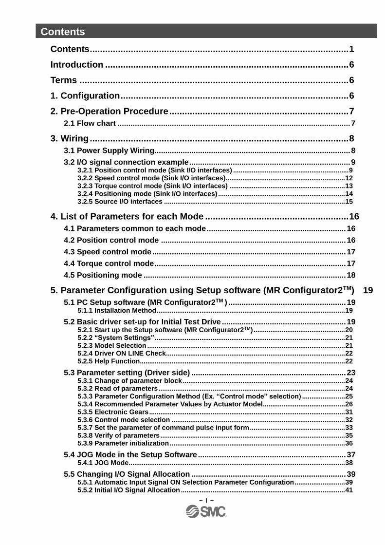
Contents
Contents ..................................................................................................... 1
Introduction ............................................................................................... 6
Terms ......................................................................................................... 6
1. Configuration ......................................................................................... 6
2. Pre-Operation Procedure ...................................................................... 7
2.1 Flow chart ........................................................................................................... 7
3. Wiring ..................................................................................................... 8
3.1 Power Supply Wiring.......................................................................................... 8
3.2 I/O signal connection example .......................................................................... 9 3.2.1 Position control mode (Sink I/O interfaces) .............................................................. 9 3.2.2 Speed control mode (Sink I/O interfaces) ................................................................ 12 3.2.3 Torque control mode (Sink I/O interfaces) .............................................................. 13 3.2.4 Positioning mode (Sink I/O interfaces) .................................................................... 14 3.2.5 Source I/O interfaces ................................................................................................. 15
4. List of Parameters for each Mode ........................................................ 16
4.1 Parameters common to each mode ................................................................ 16
4.2 Position control mode ..................................................................................... 16
4.3 Speed control mode ......................................................................................... 17
4.4 Torque control mode ........................................................................................ 17
4.5 Positioning mode ............................................................................................. 18
5. Parameter Configuration using Setup software (MR Configurator2TM) 19
5.1 PC Setup software (MR Configurator2TM ) ...................................................... 19 5.1.1 Installation Method ..................................................................................................... 19
5.2 Basic driver set-up for Initial Test Drive ......................................................... 19 5.2.1 Start up the Setup software (MR Configurator2TM) ................................................. 20 5.2.2 “System Settings” ...................................................................................................... 21 5.2.3 Model Selection .......................................................................................................... 21 5.2.4 Driver ON LINE Check ................................................................................................ 22 5.2.5 Help Function .............................................................................................................. 22
5.3 Parameter setting (Driver side) ....................................................................... 23 5.3.1 Change of parameter block ....................................................................................... 24 5.3.2 Read of parameters .................................................................................................... 24 5.3.3 Parameter Configuration Method (Ex. “Control mode” selection) ....................... 25 5.3.4 Recommended Parameter Values by Actuator Model ............................................ 26 5.3.5 Electronic Gears ......................................................................................................... 31 5.3.6 Control mode selection ............................................................................................. 32 5.3.7 Set the parameter of command pulse input form ................................................... 33 5.3.8 Verify of parameters ................................................................................................... 35 5.3.9 Parameter initialization .............................................................................................. 36
5.4 JOG Mode in the Setup Software .................................................................... 37 5.4.1 JOG Mode .................................................................................................................... 38
5.5 Changing I/O Signal Allocation ....................................................................... 39 5.5.1 Automatic Input Signal ON Selection Parameter Configuration ........................... 39 5.5.2 Initial I/O Signal Allocation ........................................................................................ 41
- 2 -
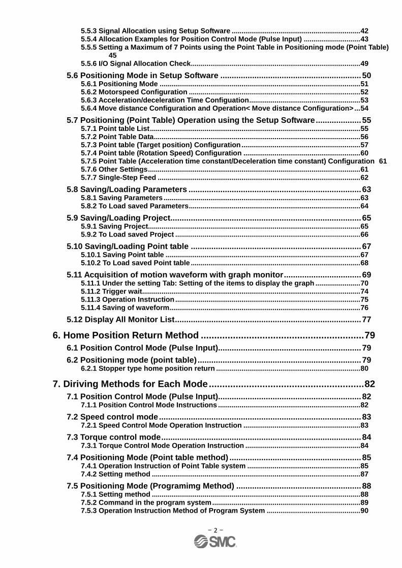
5.5.3 Signal Allocation using Setup Software .................................................................. 42 5.5.4 Allocation Examples for Position Control Mode (Pulse Input) ............................. 43 5.5.5 Setting a Maximum of 7 Points using the Point Table in Positioning mode (Point Table) 45 5.5.6 I/O Signal Allocation Check ....................................................................................... 49
5.6 Positioning Mode in Setup Software .............................................................. 50 5.6.1 Positioning Mode ....................................................................................................... 51 5.6.2 Motorspeed Configuration ........................................................................................ 52 5.6.3 Acceleration/deceleration Time Configuation ......................................................... 53 5.6.4 Move distance Configuration and Operation< Move distance Configuration> ... 54
5.7 Positioning (Point Table) Operation using the Setup Software .................... 55 5.7.1 Point table List ............................................................................................................ 55 5.7.2 Point Table Data .......................................................................................................... 56 5.7.3 Point table (Target position) Configuration ............................................................. 57 5.7.4 Point table (Rotation Speed) Configuration ............................................................ 60 5.7.5 Point Table (Acceleration time constant/Deceleration time constant) Configuration 61 5.7.6 Other Settings ............................................................................................................. 61 5.7.7 Single-Step Feed ........................................................................................................ 62
5.8 Saving/Loading Parameters ............................................................................ 63 5.8.1 Saving Parameters ..................................................................................................... 63 5.8.2 To Load saved Parameters ........................................................................................ 64
5.9 Saving/Loading Project.................................................................................... 65 5.9.1 Saving Project............................................................................................................. 65 5.9.2 To Load saved Project ............................................................................................... 66
5.10 Saving/Loading Point table ........................................................................... 67 5.10.1 Saving Point table .................................................................................................... 67 5.10.2 To Load saved Point table ....................................................................................... 68
5.11 Acquisition of motion waveform with graph monitor .................................. 69 5.11.1 Under the setting Tab: Setting of the items to display the graph ....................... 70 5.11.2 Trigger wait ................................................................................................................ 74 5.11.3 Operation Instruction ............................................................................................... 75 5.11.4 Saving of waveform .................................................................................................. 76
5.12 Display All Monitor List .................................................................................. 77
6. Home Position Return Method ............................................................. 79
6.1 Position Control Mode (Pulse Input)............................................................... 79
6.2 Positioning mode (point table) ........................................................................ 79 6.2.1 Stopper type home position return .......................................................................... 80
7. Diriving Methods for Each Mode .......................................................... 82
7.1 Position Control Mode (Pulse Input)............................................................... 82 7.1.1 Position Control Mode Instructions ......................................................................... 82
7.2 Speed control mode ......................................................................................... 83 7.2.1 Speed Control Mode Operation Instruction ............................................................ 83
7.3 Torque control mode ........................................................................................ 84 7.3.1 Torque Control Mode Operation Instruction ........................................................... 84
7.4 Positioning Mode (Point table method) .......................................................... 85 7.4.1 Operation Instruction of Point Table system .......................................................... 85 7.4.2 Setting method ........................................................................................................... 87
7.5 Positioning Mode (Programimg Method) ....................................................... 88 7.5.1 Setting method ........................................................................................................... 88 7.5.2 Command in the program system ............................................................................ 89 7.5.3 Operation Instruction Method of Program System ................................................ 90

- 3 -
8. Troubleshooting .................................................................................... 91
8.1 Alarms and Warning List ................................................................................. 91
8.2 Alarm Display.................................................................................................... 93

- 4 -
LECSA Series / Driver Safety Instructions
These safety instructions are intended to prevent hazardous situations and/or equipment damage. These instructions
indicate the level of potential hazard with the labels of “Caution,” “Warning” or “Danger”. They are all important notes for
safety and must be followed in addition to International Standards (ISO/IEC), Japan Industrial Standards (JIS) *1.) and
other safety regulations*2.). *1) ISO 4414: Pneumatic fluid power -- General rules relating to systems
ISO 4413: Hydraulic fluid power -- General rules relating to systems
IEC 60204-1: Safety of machinery -- Electrical equipment of machines (Part 1: General requirements)
ISO 10218: Manipulating industrial robots -- Safety
*2) Labor Safety and Sanitation Law, etc.
Caution Caution indicates a hazard with a low level of risk which, if not avoided, could result in minor or
moderate injury.
Warning Warning indicates a hazard with a medium level of risk which, if not avoided, could result in death
or serious injury.
Danger Danger indicates a hazard with a high level of risk which, if not avoided, will result in death or
serious injury.
Warning 1. The compatibility of the product is the responsibility of the person who designs the equipment or
decides its specifications. Since the product specified here is used under various operating conditions, its compatibility with specific equipment must be decided by the person who designs the equipment or decides its specifications based on necessary analysis and test results. The expected performance and safety assurance of the equipment will be the responsibility of the person who has determined its compatibility with the product. This person should also continuously review all specifications of the product referring to its latest catalog information, with a view to giving due consideration to any possibility of equipment failure when configuring the equipment.
2. Only personnel with appropriate training should operate machinery and equipment. The product specified here may become unsafe if handled incorrectly. The assembly, operation and maintenance of machines or equipment including our products must be performed by an operator who is appropriately trained and experienced.
3. Do not service or attempt to remove product and machinery/equipment until safety is confirmed. The inspection and maintenance of machinery/equipment should only be performed after measures to prevent falling or runaway of the driven objects have been confirmed. When the product is to be removed, confirm that the safety measures as mentioned above are implemented and the power from any appropriate source is cut, and read and understand the specific product precautions of all relevant products carefully. Before machinery/equipment is restarted, take measures to prevent unexpected operation and malfunction.
4. Contact SMC beforehand and take special consideration of safety measures if the product is to be used in any of the following conditions. 1) Conditions and environments outside of the given specifications, or use outdoors or in a place exposed to direct sunlight. 2) Installation on equipment in conjunction with atomic energy, railways, air navigation, space, shipping, vehicles, military, medical treatment, combustion and recreation, or equipment in contact with food and beverages, emergency stop circuits, clutch and lock circuits in press applications, safety equipment or other applications unsuitable for the standard specifications described in the product catalog. 3) An application which could have negative effects on people, property, or animals requiring special safety analysis. 4) Use in an interlock circuit, which requires the provision of double interlock for possible failure by using a mechanical protective function, and periodical checks to confirm proper operation.
Note that the CAUTION level may lead to a serious consequence according to conditions. Please follow the
instructions of both levels because they are important to personnel safety.
- 5 -
LECSA Series / Driver Safety Instructions
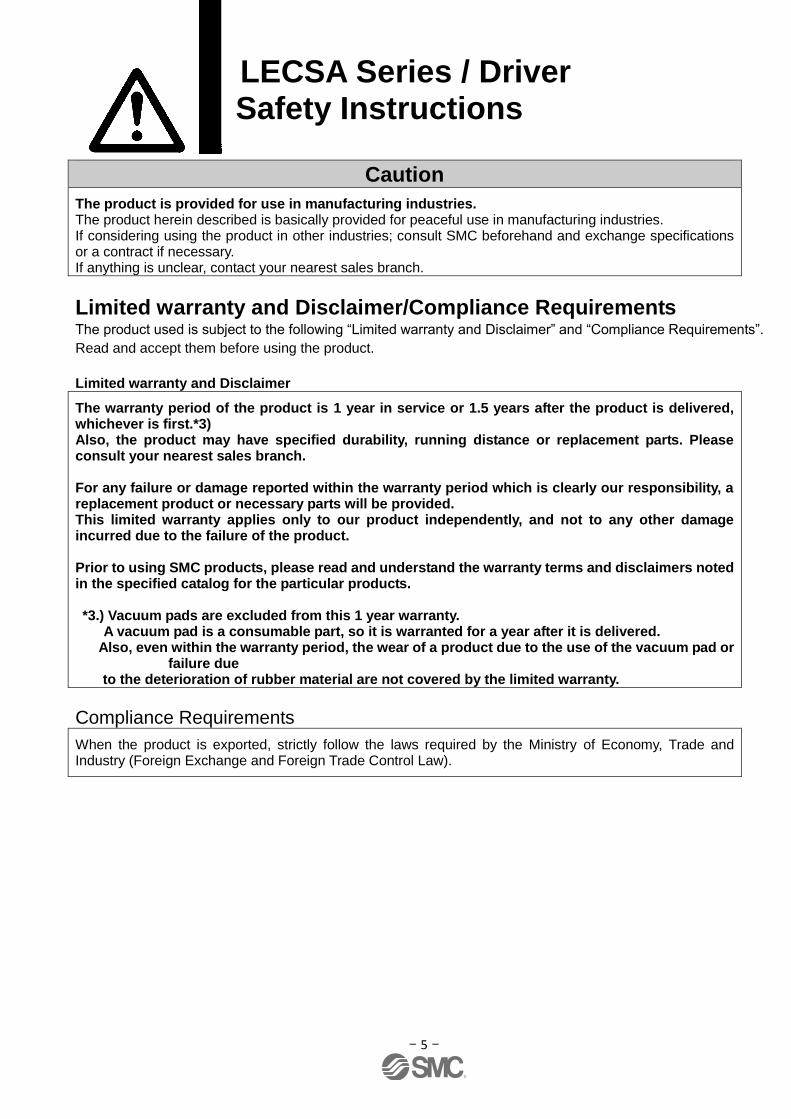
Caution
The product is provided for use in manufacturing industries. The product herein described is basically provided for peaceful use in manufacturing industries. If considering using the product in other industries; consult SMC beforehand and exchange specifications or a contract if necessary. If anything is unclear, contact your nearest sales branch.
Limited warranty and Disclaimer/Compliance Requirements The product used is subject to the following “Limited warranty and Disclaimer” and “Compliance Requirements”.
Read and accept them before using the product.
Limited warranty and Disclaimer
The warranty period of the product is 1 year in service or 1.5 years after the product is delivered, whichever is first.*3) Also, the product may have specified durability, running distance or replacement parts. Please consult your nearest sales branch. For any failure or damage reported within the warranty period which is clearly our responsibility, a replacement product or necessary parts will be provided. This limited warranty applies only to our product independently, and not to any other damage incurred due to the failure of the product. Prior to using SMC products, please read and understand the warranty terms and disclaimers noted in the specified catalog for the particular products. *3.) Vacuum pads are excluded from this 1 year warranty. A vacuum pad is a consumable part, so it is warranted for a year after it is delivered.
Also, even within the warranty period, the wear of a product due to the use of the vacuum pad or failure due
to the deterioration of rubber material are not covered by the limited warranty.
Compliance Requirements
When the product is exported, strictly follow the laws required by the Ministry of Economy, Trade and Industry (Foreign Exchange and Foreign Trade Control Law).
- 6 -
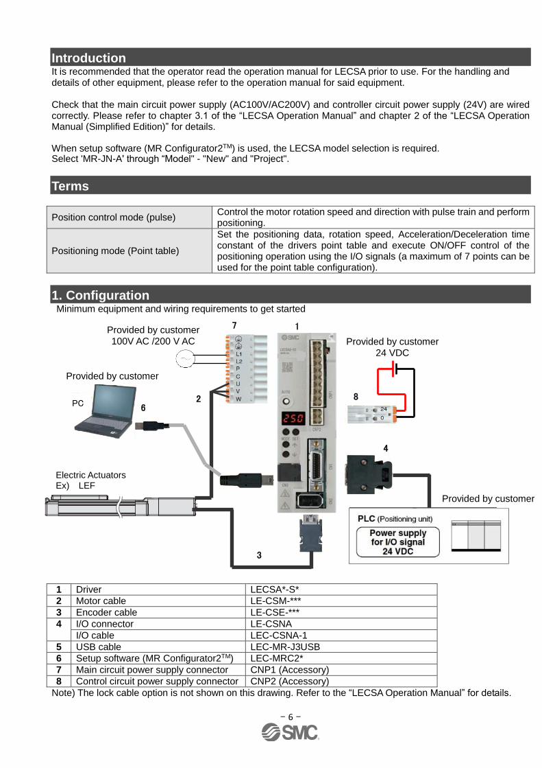
Introduction It is recommended that the operator read the operation manual for LECSA prior to use. For the handling and details of other equipment, please refer to the operation manual for said equipment. Check that the main circuit power supply (AC100V/AC200V) and controller circuit power supply (24V) are wired correctly. Please refer to chapter 3.1 of the “LECSA Operation Manual” and chapter 2 of the “LECSA Operation Manual (Simplified Edition)” for details. When setup software (MR Configurator2TM) is used, the LECSA model selection is required. Select 'MR-JN-A' through “Model" - "New" and "Project".
Terms
Position control mode (pulse) Control the motor rotation speed and direction with pulse train and perform positioning.
Positioning mode (Point table)
Set the positioning data, rotation speed, Acceleration/Deceleration time constant of the drivers point table and execute ON/OFF control of the positioning operation using the I/O signals (a maximum of 7 points can be used for the point table configuration).
1. Configuration Minimum equipment and wiring requirements to get started 1 Driver LECSA*-S*
2 Motor cable LE-CSM-***
3 Encoder cable LE-CSE-***
4 I/O connector LE-CSNA
I/O cable LEC-CSNA-1
5 USB cable LEC-MR-J3USB
6 Setup software (MR Configurator2TM) LEC-MRC2*
7 Main circuit power supply connector CNP1 (Accessory)
8 Control circuit power supply connector CNP2 (Accessory)
Note) The lock cable option is not shown on this drawing. Refer to the “LECSA Operation Manual” for details.
8
3
4
6 2
1 7
Electric Actuators Ex) LEF
PC
Provided by customer 24 VDC
Provided by customer 100V AC /200 V AC
Provided by customer
Provided by customer

- 7 -
2. Pre-Operation Procedure
2.1 Flow chart
Wiring See “3. Wiring”
Parameter setting See “4. List of Parameters for each Mode”
Signal Assignment Configuration See “5.5 Changing I/O Signal Allocation”
Parameter Settings using the Setup Software (MR Configurator2TM)
See “5. Parameter Settings using the Setup Software (MR Configurator2TM)”
Home position return Method See ”6. Home position return
Method”
Home position return Method
See “6.Home
position return Method”
“Position Control Mode” Configuration
See “7.1 Position Control Mode (Pulse input)”
“Positioning mode” Configuration
See “7.4. Positioning mode (Point table method)” See “7.5. Positioning Mode (Program method)”
“Speed control mode” Configuration
See “7.2 Speed control mode”
“Torque control mode” Configuration
See “7.3 Torque control mode”
Simple positioning mode which is operable using I/O signals -Point table method -Program method
Speed control though specifying the internal set speed using I/O signals
Position control using pulse train input
Thrust control through specifying the internal set torque using I/O signals
- 8 -
3. Wiring
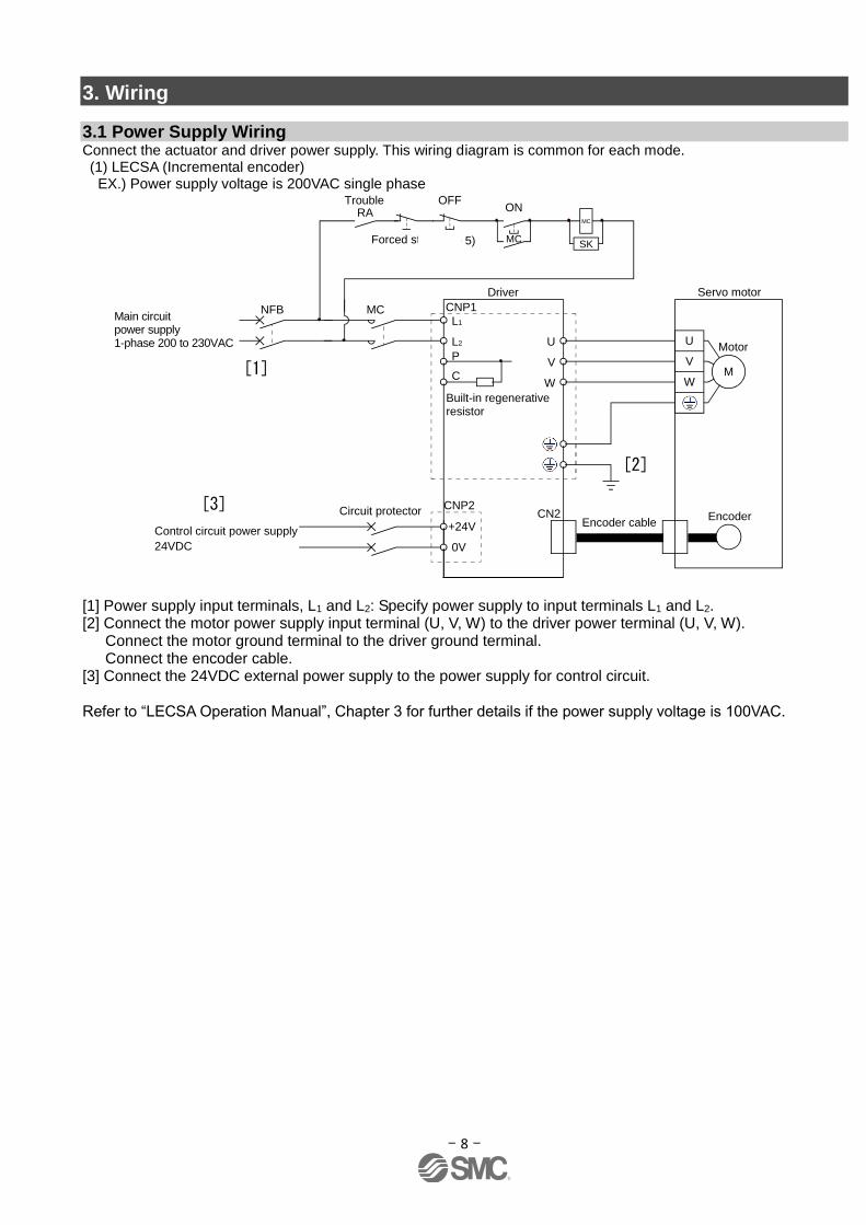
3.1 Power Supply Wiring Connect the actuator and driver power supply. This wiring diagram is common for each mode. (1) LECSA (Incremental encoder)
EX.) Power supply voltage is 200VAC single phase
SON
EM1
L1
L2
Main circuit power supply 1-phase 200 to 230VAC
ALM
P
C
DICOM
DOCOM
+24V
0V
U
V
W
Control circuit power supply
CNP1
CNP2
U
V
WM
Motor
EncoderCN2Encoder cable
DOCOM
CN1 CN1 24VDC
Trouble
MCNFB
RA
Servo motorServo amplifier
Forced stop (Note 5)
Servo-on
RAOFFTrouble
MC
ONMC
SK(Note 5)Forced stop
(Note 6)
Circuit protector
(Note 4)
(Note 2)
(Note 3)
(Note 3)
24VDC (Note 7)
(Note 1)Built-in regenerativeresistor
[1] Power supply input terminals, L1 and L2: Specify power supply to input terminals L1 and L2. [2] Connect the motor power supply input terminal (U, V, W) to the driver power terminal (U, V, W). Connect the motor ground terminal to the driver ground terminal. Connect the encoder cable. [3] Connect the 24VDC external power supply to the power supply for control circuit. Refer to “LECSA Operation Manual”, Chapter 3 for further details if the power supply voltage is 100VAC.
Driver
[1]
[3]
[2]
- 9 -
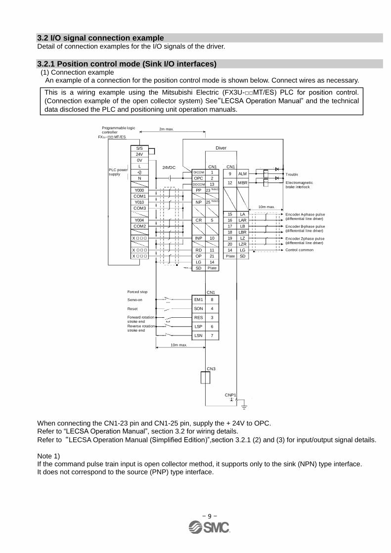
3.2 I/O signal connection example Detail of connection examples for the I/O signals of the driver.
3.2.1 Position control mode (Sink I/O interfaces) (1) Connection example
An example of a connection for the position control mode is shown below. Connect wires as necessary.
COM3
X
X
9 ALM
15 LA
16 LAR
17 LB
18 LBR
19 LZ
20 LZR
14 LG
SD
RD
14
11
21
23
2
25
5
1
L
N
COM2
Y000
COM1
Y004
Y010
OP
LG
PP
OPC
NP
DICOM
DOCOM
CR
13
RA1
RA2
8
4
3
6
7
EM1
SON
RES
LSP
LSN
S/S
24V
0V
12 MBR
X INP 10
CNP1
SD
(Note 10, 12)
Trouble (Note 6)
Electromagnetic brake interlock
Encoder A-phase pulse(differential line driver)
Encoder B-phase pulse(differential line driver)
Control common
Encoder Z-phase pulse(differential line driver)
Forward rotation stroke end
Reverse rotation stroke end
(Note 3, 5)
(Note 5)
(Note 10, 11)
(Note 9)
Servo-on
Reset
10m max.
(Note 1 )
USB cable(option)
MR Configurator
CN3
Personalcomputer
(Note 14)
(Note 15)
Servo amplifier
10m max.
2m max. (Note 8)
(Note 7)
Programmable logic controller
FX3U- MT/ES (Note 13)
(Note 7)
Plate
Plate
CN1 CN124VDC(Note 4, 10 )
(Note 2 )
Forced stop CN1(Note 7 )
PLC power supply
When connecting the CN1-23 pin and CN1-25 pin, supply the + 24V to OPC. Refer to “LECSA Operation Manual”, section 3.2 for wiring details.
Refer to “LECSA Operation Manual (Simplified Edition)”,section 3.2.1 (2) and (3) for input/output signal details.
Note 1) If the command pulse train input is open collector method, it supports only to the sink (NPN) type interface. It does not correspond to the source (PNP) type interface.
This is a wiring example using the Mitsubishi Electric (FX3U-□□MT/ES) PLC for position control.
(Connection example of the open collector system) See“LECSA Operation Manual” and the technical
data disclosed the PLC and positioning unit operation manuals.
Diver
23 Note1)
25 Note1)

- 10 -
(2) Input signal Position control mode: P, Speed control mode: S, Torque control mode: T, Point table method: CP, Program method: CL
●: Automatic ON can be set, ○: Initial setting, □: Assignment is available with parameter,-: Assignment is not available
Symbol Device name Automatic
ON P S T
CP/ CL
Function
PP Forward rotation
pulse train - ○ - - -
In the open collector system
(max. input frequency 200kpps)
Forward rotation pulse train across PP-DOCOM
Reverse rotation pulse train across NP-DOCOM
It supports only to the sink (NPN) type interface.
It does not correspond to the source (PNP) type
interface.
NP Reverse rotation
pulse train - ○ - - -
PG Differential
forward rotation pulse train
- ○ - - - In the differential receiver system
(max. input frequency 1Mpps)
Forward rotation pulse train across PG-PP
Reverse rotation pulse train across NG-NP NG Differential
reverse rotation pulse train
- ○ - - -
SON Servo-on ● ○ ○ ○ ○ Operation is available when SON is turned ON.
RES Reset - ○ ○ ○ □ Alarm can be reset.
LSP Forward rotation
stroke end ● ○ □ - □
Turn this signal on before operation. When this signal turns off, the product is stopped suddenly and servo lock is enabled.
LSN Reverse rotation
stroke end ● ○ □ - □
Turn this signal on before operation. When this signal turns off, the product is stopped suddenly and servo lock is enabled.
TL1 Internal torque limit selection
- □ □ □ □ When this signal turns on, the torque will be lower than the set parameter torque.
ST1 Forward rotation
start - - ○ - ○ Start the servo motor.
ST2 Reverse rotation
start - - ○ - ○ Start the servo motor.
RS1 Forward rotation
selection - - - ○ -
Servo motor torque generating direction is selected.
RS2 Reverse rotation
selection - - - ○ -
Servo motor torque generating direction is selected.
SP1 Speed selection 1 - - ○ ○ - The command rotation speed during operation is selected.
SP2 Speed selection 2 - - □ □ -
SP3 Speed selection 3 - - □ □ -
EM1 Forced stop ● ○ ○ ○ ○ When this signal turns on, forced stop can be released.
CR Clear - ○ - - - When CR is turned on, the droop pulses of the position control counter are cleared on its leading edge.
DI0 Point table No/ Program No. selection 1
● - - - ○
Select point table, program and return to home position mode with DI0 to DI2.
DI1 Point table No/
Program No selection 2
● - - - ○
DI2 Point table No/
Program No selection 3
● - - - □
MD0 Automatic/manual
selection ● - - - ○
When this signal turns on, automatic operation mode is activated. When this signal turns off, manual operation mode is activated.
- 11 -
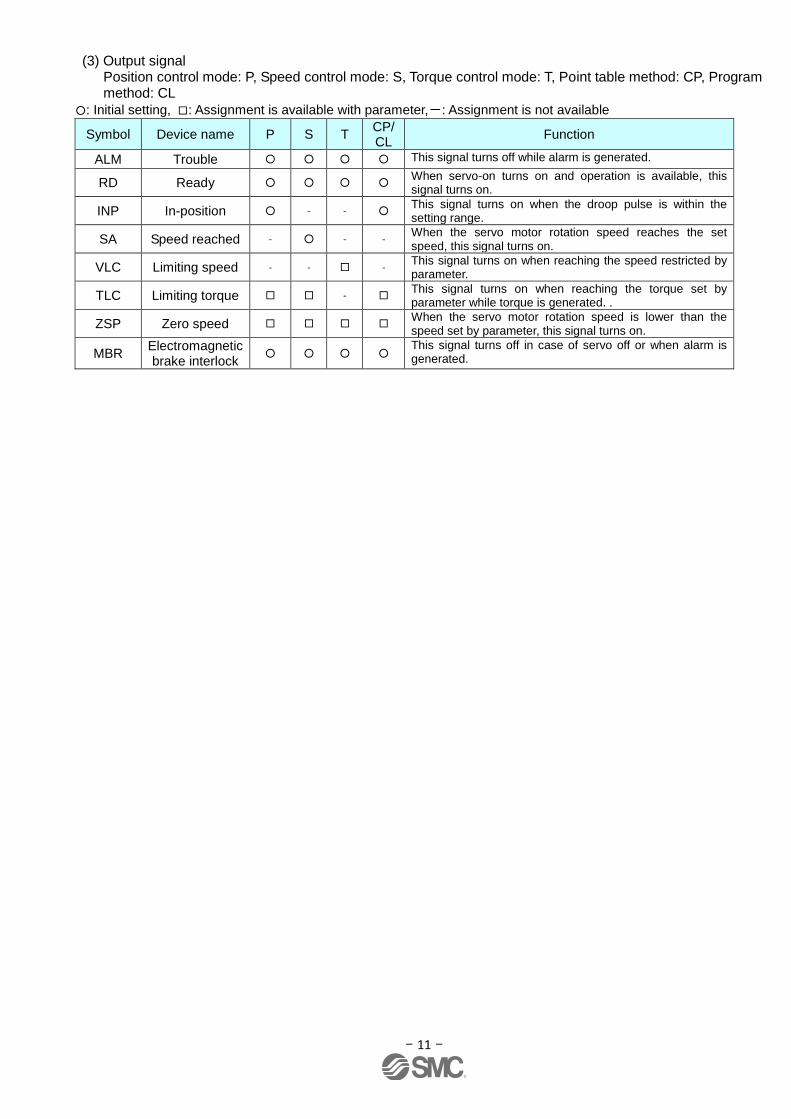
(3) Output signal Position control mode: P, Speed control mode: S, Torque control mode: T, Point table method: CP, Program method: CL
○: Initial setting, □: Assignment is available with parameter,-: Assignment is not available
Symbol Device name P S T CP/ CL
Function
ALM Trouble ○ ○ ○ ○ This signal turns off while alarm is generated.
RD Ready ○ ○ ○ ○ When servo-on turns on and operation is available, this signal turns on.
INP In-position ○ - - ○ This signal turns on when the droop pulse is within the setting range.
SA Speed reached - ○ - - When the servo motor rotation speed reaches the set speed, this signal turns on.
VLC Limiting speed - - □ - This signal turns on when reaching the speed restricted by parameter.
TLC Limiting torque □ □ - □ This signal turns on when reaching the torque set by parameter while torque is generated. .
ZSP Zero speed □ □ □ □ When the servo motor rotation speed is lower than the speed set by parameter, this signal turns on.
MBR Electromagnetic brake interlock
○ ○ ○ ○ This signal turns off in case of servo off or when alarm is generated.
- 12 -
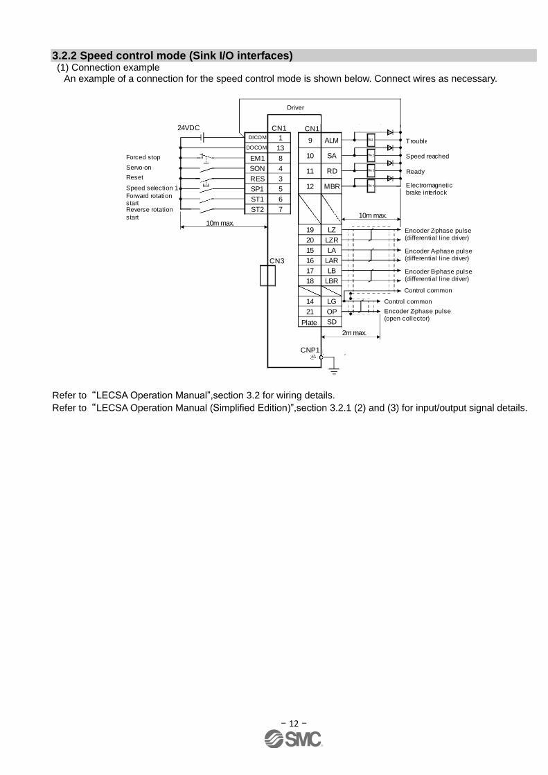
3.2.2 Speed control mode (Sink I/O interfaces) (1) Connection example
An example of a connection for the speed control mode is shown below. Connect wires as necessary.
LZ
Plate
Servo amplifier
Trouble (Note 6)
Electromagnetic brake interlock
9 ALM
10 SA
11 RD
12 MBR
CN1
Speed reached
Ready
Encoder A-phase pulse(differential line driver)
15 LA
16 LAR
17 LB
18 LBR
14 LG
21 OP
SD
2m max.
Encoder B-phase pulse(differential line driver)
Control common
Encoder Z-phase pulse(open collector)
Encoder Z-phase pulse(differential line driver)
19
20 LZR
CN1
1
13
DICOM
DOCOM
10m max.
USB cable(option)
CN3
MR Configurator
Personalcomputer
24VDC
RA1
RA 2
RA 3
RA 4
8
4
3
7
Forced stop
Servo-on
Reset
Forward rotation startReverse rotation
start
(Note 3, 5)
5
6
Speed selection 1
EM1
SON
RES
ST1
ST2
SP1
(Note 9, 10, 12)
(Note 4, 9)(Note 7)
(Note 2)
(Note 9, 11)
10m max.
(Note 1)
(Note 8)
(Note 7)
Control common
CNP1
Refer to“LECSA Operation Manual”,section 3.2 for wiring details.
Refer to “LECSA Operation Manual (Simplified Edition)”,section 3.2.1 (2) and (3) for input/output signal details.
Driver
- 13 -
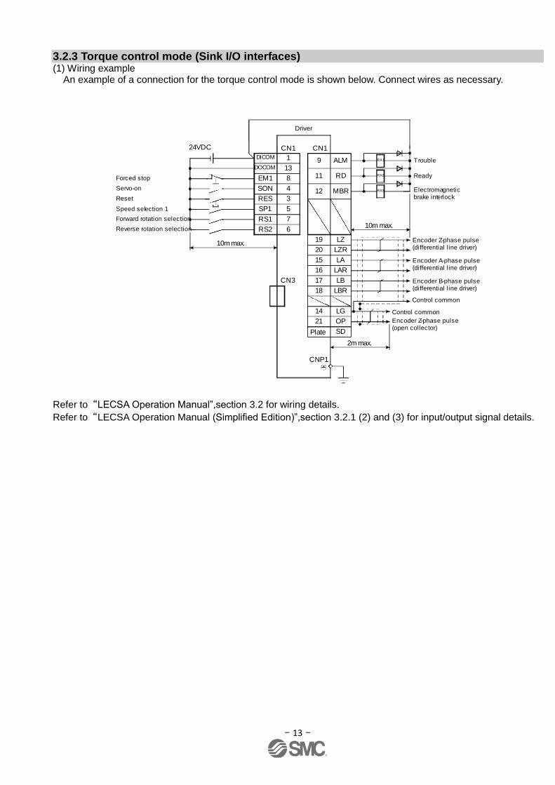
3.2.3 Torque control mode (Sink I/O interfaces) (1) Wiring example
An example of a connection for the torque control mode is shown below. Connect wires as necessary.
CNP1
24VDC (Note 4, 8)
Servo amplifier
20
Trouble (Note 5)
Electromagnetic brake interlock
Encoder A-phase pulse(differential line driver)
9 ALM
11 RD
12 MBR
15 LA
16 LAR
17 LB
18 LBR
14 LG
21 OP
SD
2m max.
Encoder B-phase pulse(differential line driver)
Control common
Encoder Z-phase pulse(open collector)
CN1
Ready
Encoder Z-phase pulse(differential line driver)
19 LZ
LZR
(Note 6)CN1
1
13
DICOM
DOCOM
Personalcomputer
USB cable(option)
CN3
10m max.
(Note 7)MR Configurator
(Note 8, 10)
Plate
(Note 8, 9)
8
4
3
6
7
Forced stop
Servo-on
Reset
Forward rotation selection
Reverse rotation selection
(Note 3)
5
EM1
SON
RES
RS1
RS2
SP1Speed selection 1
RA1
RA2
RA3
(Note 6)(Note 2)
10m max.
Control common
(Note 1)
Refer to“LECSA Operation Manual”,section 3.2 for wiring details.
Refer to “LECSA Operation Manual (Simplified Edition)”,section 3.2.1 (2) and (3) for input/output signal details.
Driver
- 14 -
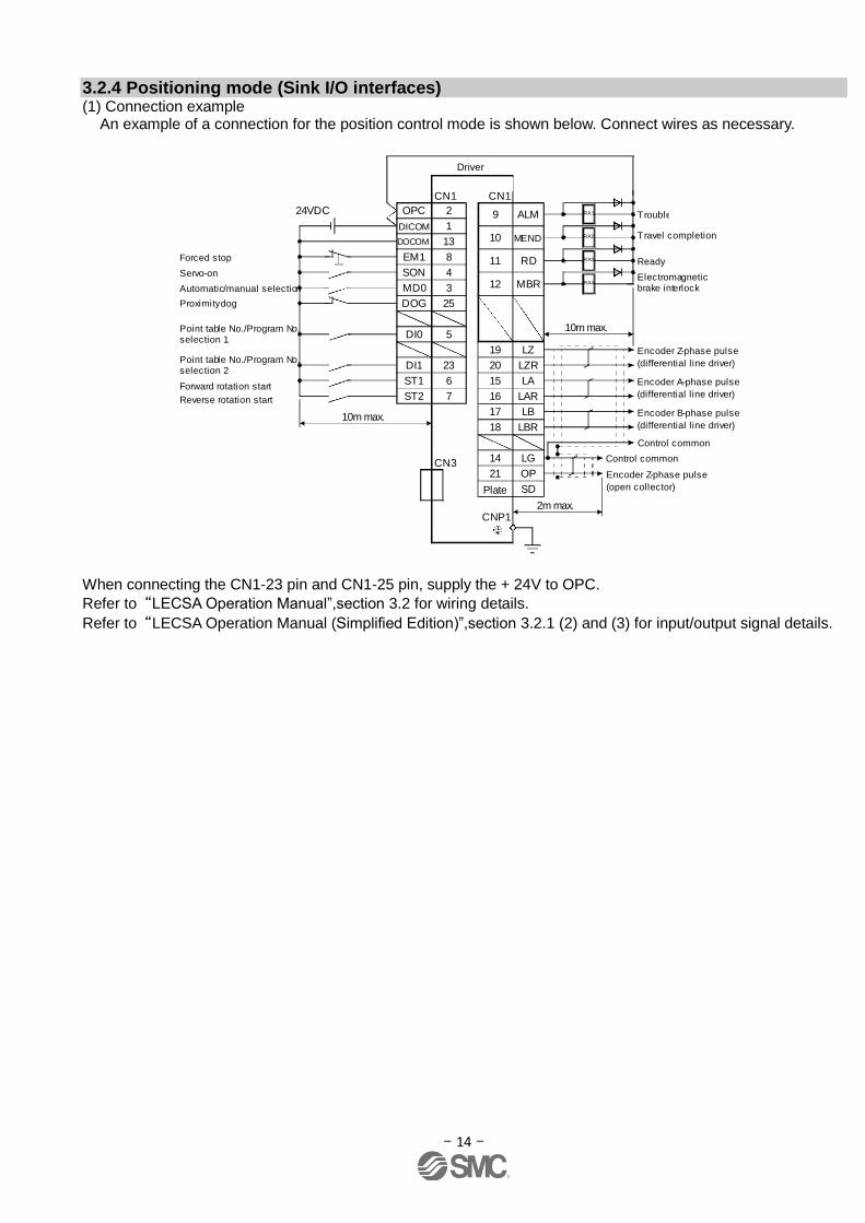
3.2.4 Positioning mode (Sink I/O interfaces) (1) Connection example
An example of a connection for the position control mode is shown below. Connect wires as necessary.
LZ
Plate
Servo amplifier
(Note 1)
(Note 2)
Trouble (Note 6)
Electromagnetic brake interlock
9 ALM
10 MEND
11 RD
12 MBR
(Note 7)CN1
Travel completion
(Note 13)
Ready
15 LA
16 LAR
17 LB
18 LBR
14 LG
21 OP
SD
10m max.
2m max.
Encoder B-phase pulse
(differential line driver)
Control common
Encoder Z-phase pulse
(open collector)
Encoder Z-phase pulse
(differential line driver)
19
20 LZR
(Note 7)CN1
1
13
DICOM
DOCOM
10m max.
+
CN3
(Note 8)MR Configurator
Personal computer
24VDC RA1
RA2
RA3
RA4
(Note 4, 9)
(Note 9, 11)8
4
3
7
Forced stop
Servo-on
Automatic/manual selection
Forward rotation start
Reverse rotation start
(Note 3, 5)
25
6
Proximity dog
EM1
SON
MD0
ST1
ST2
DOG(Note 9,
10, 12)
5DI0
23DI1Point table No./Program No. selection 2
Point table No./Program No. selection 1
CNP1
2OPC
Control common
Encoder A-phase pulse
(differential line driver)
USB cable(option)
When connecting the CN1-23 pin and CN1-25 pin, supply the + 24V to OPC.
Refer to“LECSA Operation Manual”,section 3.2 for wiring details.
Refer to “LECSA Operation Manual (Simplified Edition)”,section 3.2.1 (2) and (3) for input/output signal details.
Driver
- 15 -
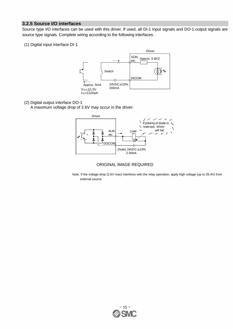
3.2.5 Source I/O interfaces Source type I/O interfaces can be used with this driver. If used, all DI-1 input signals and DO-1 output signals are
source type signals. Complete wiring according to the following interfaces.
(1) Digital input interface DI-1
SON,etc.
Servo amplifier
Switch
Approx. 5mA
DICOM
VCES 1.0VICEO 100 A
24VDC 10%200mA
Approx. 5.6k
(2) Digital output interface DO-1 A maximum voltage drop of 2.6V may occur in the driver.
(Note) 24VDC 10% 2 00mA
If polarity of diode isreversed, servoamplifier will fail.
Servo amplifier
ALM,etc.
Load
DOCOM
ORIGINAL IMAGE REQUIRED
Note. If the voltage drop (2.6V max) interferes with the relay operation, apply high voltage (up to 26.4V) from
external source.
Driver
Driver
driver
- 16 -
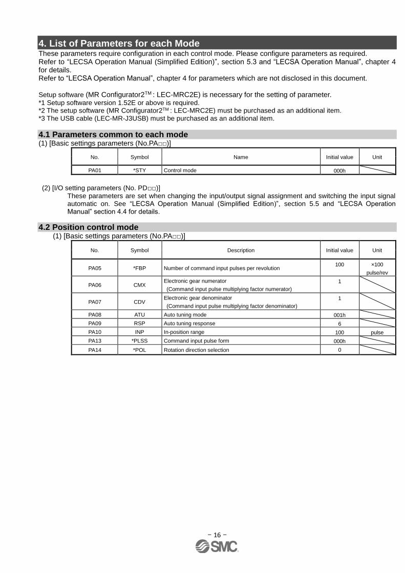
4. List of Parameters for each Mode These parameters require configuration in each control mode. Please configure parameters as required. Refer to “LECSA Operation Manual (Simplified Edition)”, section 5.3 and “LECSA Operation Manual”, chapter 4 for details. Refer to “LECSA Operation Manual”, chapter 4 for parameters which are not disclosed in this document. Setup software (MR Configurator2TM : LEC-MRC2E) is necessary for the setting of parameter. *1 Setup software version 1.52E or above is required. *2 The setup software (MR Configurator2TM : LEC-MRC2E) must be purchased as an additional item. *3 The USB cable (LEC-MR-J3USB) must be purchased as an additional item.
4.1 Parameters common to each mode (1) [Basic settings parameters (No.PA□□)]
No. Symbol Name Initial value Unit
PA01 *STY Control mode 000h
(2) [I/O setting parameters (No. PD□□)]
These parameters are set when changing the input/output signal assignment and switching the input signal automatic on. See “LECSA Operation Manual (Simplified Edition)”, section 5.5 and “LECSA Operation Manual” section 4.4 for details.
4.2 Position control mode (1) [Basic settings parameters (No.PA□□)]
No. Symbol Description Initial value Unit
PA05 *FBP Number of command input pulses per revolution 100 ×100
pulse/rev
PA06 CMX Electronic gear numerator
(Command input pulse multiplying factor numerator)
1
PA07 CDV Electronic gear denominator
(Command input pulse multiplying factor denominator)
1
PA08 ATU Auto tuning mode 001h
PA09 RSP Auto tuning response 6
PA10 INP In-position range 100 pulse
PA13 *PLSS Command input pulse form 000h
PA14 *POL Rotation direction selection 0
- 17 -
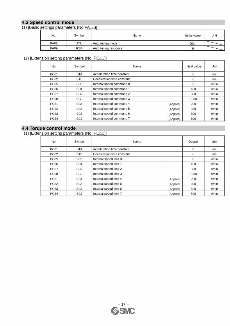
4.3 Speed control mode (1) [Basic settings parameters (No.PA□□)]
No. Symbol Name Initial value Unit
PA08 ATU Auto tuning mode 001h
PA09 RSP Auto tuning response 6
(2) [Extension setting parameters (No. PC□□)]
No. Symbol Name Initial value Unit
PC01 STA Acceleration time constant 0 ms
PC02 STB Deceleration time constant 0 ms
PC05 SC0 Internal speed command 0 0 r/min
PC06 SC1 Internal speed command 1 100 r/min
PC07 SC2 Internal speed command 2 500 r/min
PC08 SC3 Internal speed command 3 1000 r/min
PC31 SC4 Internal speed command 4 [Applied] 200 r/min
PC32 SC5 Internal speed command 5 [Applied] 300 r/min
PC33 SC6 Internal speed command 6 [Applied] 500 r/min
PC34 SC7 Internal speed command 7 [Applied] 800 r/min
4.4 Torque control mode (1) [Extension setting parameters (No. PC□□)]
No. Symbol Name Default Unit
PC01 STA Acceleration time constant 0 ms
PC02 STB Deceleration time constant 0 ms
PC05 SC0 Internal speed limit 0 0 r/min
PC06 SC1 Internal speed limit 1 100 r/min
PC07 SC2 Internal speed limit 2 500 r/min
PC08 SC3 Internal speed limit 3 1000 r/min
PC31 SC4 Internal speed limit 4 [Applied] 200 r/min
PC32 SC5 Internal speed limit 5 [Applied] 300 r/min
PC33 SC6 Internal speed limit 6 [Applied] 500 r/min
PC34 SC7 Internal speed limit 7 [Applied] 800 r/min
- 18 -
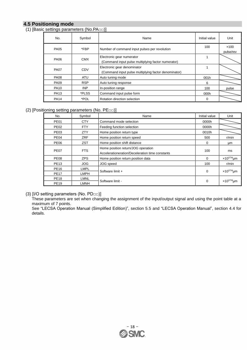
4.5 Positioning mode (1) [Basic settings parameters (No.PA□□)]
No. Symbol Name Initial value Unit
PA05 *FBP Number of command input pulses per revolution 100 ×100
pulse/rev
PA06 CMX Electronic gear numerator
(Command input pulse multiplying factor numerator)
1
PA07 CDV Electronic gear denominator
(Command input pulse multiplying factor denominator)
1
PA08 ATU Auto tuning mode 001h
PA09 RSP Auto tuning response 6
PA10 INP In-position range 100 pulse
PA13 *PLSS Command input pulse form 000h
PA14 *POL Rotation direction selection 0
(2) [Positioning setting parameters (No. PE□□)]
No. Symbol Name Initial value Unit
PE01 CTY Command mode selection 0000h
PE02 FTY Feeding function selection 0000h
PE03 ZTY Home position return type 0010h
PE04 ZRF Home position return speed 500 r/min
PE06 ZST Home position shift distance 0 μm
PE07 FTS Home position return/JOG operation
Accelerationeration/Deceleration time constants 100 ms
PE08 ZPS Home position return position data 0 ×10STMμm
PE13 JOG JOG speed 100 r/min
PE16 LMPL Software limit + 0 ×10STMμm
PE17 LMPH
PE18 LMNL Software limit - 0 ×10STMμm
PE19 LMNH
(3) [I/O setting parameters (No. PD□□)]
These parameters are set when changing the assignment of the input/output signal and using the point table at a maximum of 7 points. See “LECSA Operation Manual (Simplified Edition)”, section 5.5 and “LECSA Operation Manual”, section 4.4 for details.
- 19 -
5. Parameter Configuration using Setup software (MR Configurator2TM) This section describes the configuration procedure for main parameters using the setup software (MR Configurator2TM: LEC-MRC2E). See chapter 4 of the “LECSA Operation Manual” for parameter details.
5.1 PC Setup software (MR Configurator2TM )
*1 Setup software version 1.52E or above is required. *2 The setup software (MR Configurator2TM : LEC-MRC2E) must be purchased as an additional item. *3 The USB cable (LEC-MR-J3USB) must be purchased as an additional item.
5.1.1 Installation Method Perform installation according to the “MR Configurator2TM instruction manual” (Manual/ib0300160*.pdf) contained on the setup software (MR Configurator2TM) CD-ROM. The “MR Configurator2” software will be added to the PC.
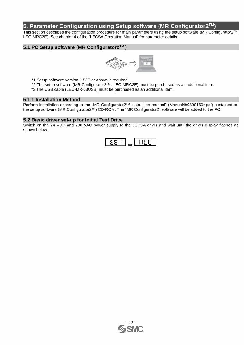
5.2 Basic driver set-up for Initial Test Drive Switch on the 24 VDC and 230 VAC power supply to the LECSA driver and wait until the driver display flashes as shown below.

- 20 -
5.2.1 Start up the Setup software (MR Configurator2TM) ① Connect the PC and LECSA using the USB cable.
② Turn on the power of the LECSA.
③ Start application “MR Configurator2”.
Once the application starts, the screen below will be displayed.
- 21 -
5.2.2 “System Settings”
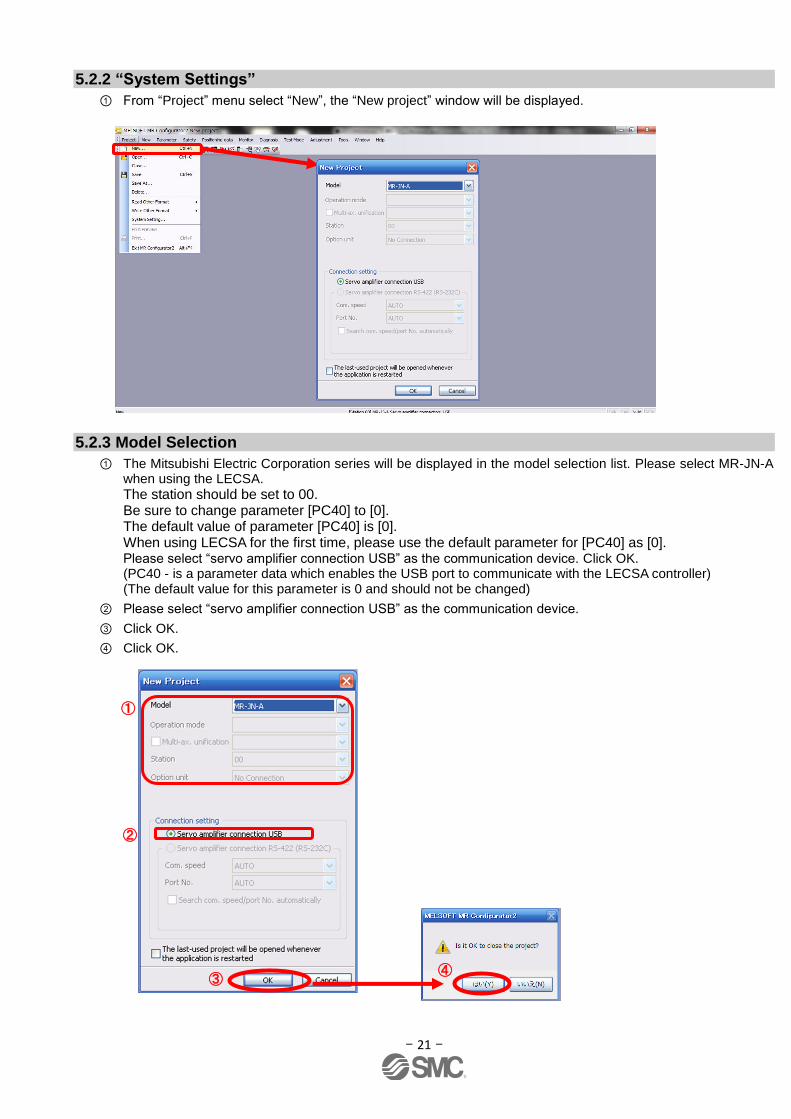
① From “Project” menu select “New”, the “New project” window will be displayed.
5.2.3 Model Selection
① The Mitsubishi Electric Corporation series will be displayed in the model selection list. Please select MR-JN-A when using the LECSA.
The station should be set to 00. Be sure to change parameter [PC40] to [0]. The default value of parameter [PC40] is [0]. When using LECSA for the first time, please use the default parameter for [PC40] as [0]. Please select “servo amplifier connection USB” as the communication device. Click OK. (PC40 - is a parameter data which enables the USB port to communicate with the LECSA controller) (The default value for this parameter is 0 and should not be changed)
② Please select “servo amplifier connection USB” as the communication device.
③ Click OK.
④ Click OK.
①
②
③ ④

- 22 -
5.2.4 Driver ON LINE Check Check that the driver is enabled (ONLINE).
Check that the “ONLINE/OFFLINE” icon is displayed “ ”. When It is OFFLINE it is displayed as “ ”. * For OFFLine, PC and amplifier aren’t communicating. Confirm the following points. - Is amplifier's power supply turned on? - Is the PC and LECSA amplifier connected with the USB cable? - Is the USB driver installed?
- Is the USB driver which is compliant to Windows version installed? - Is parameter [PC40] set to [0]? (PC40 - is a parameter data which enables the USB port to communicate with the LECSA controller) (The default value for this parameter is 0 and should not be changed)
5.2.5 Help Function By selecting “MR Configurator2 Help” in “Help” from any window of the setup software, a “HELP” screen will be shown.

- 23 -
5.3 Parameter setting (Driver side) The setup software (MR Configurator2TM: LEC-MRC2E) is necessary for setting the parameter.
*1 Setup software version 1.52E or above is required. *2 The setup software (MR Configurator2TM: LEC-MRC2E) must be purchased as an additional item. *3 The USB cable (LEC-MR-J3USB) must be purchased as an additional item.
① From the “Parameter” menu select “Parameter Setting”, the “parameter setting” window will open.
② The explanation of the parameter item is displayed in “MR2 Help”. (When it is not displayed, from the “View” menu select “Docking window” – “Docking Help”.)
③ When each item of “List display” is clicked, “Parameter list” screen along each item is displayed. When “Basic” is selected, it is displayed as follows.
Refer to"LECSA Operation Manual”, chapter 4 for details of each parameter.
①
②
③
- 24 -
5.3.1 Change of parameter block To enable settings for all parameters.
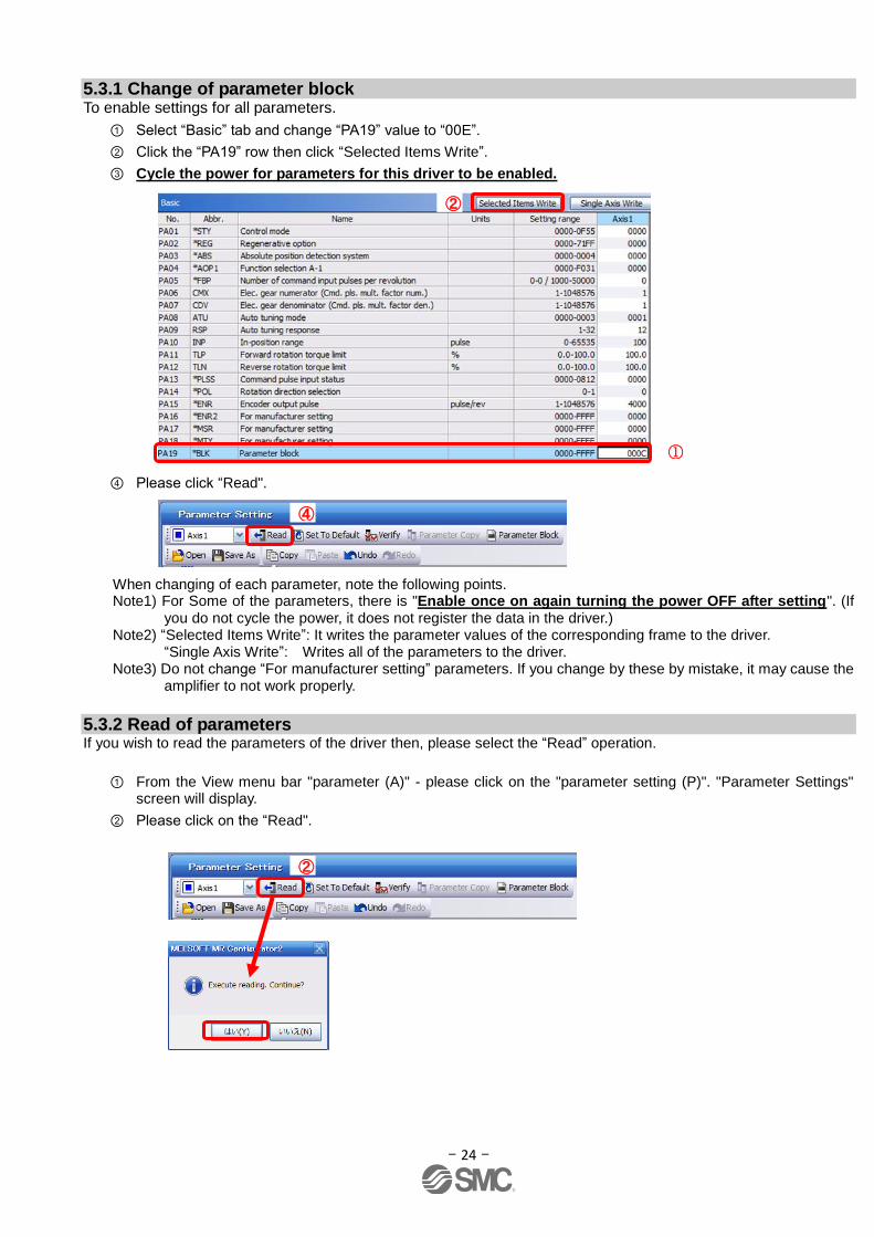
① Select “Basic” tab and change “PA19” value to “00E”.
② Click the “PA19” row then click “Selected Items Write”.
③ Cycle the power for parameters for this driver to be enabled.
④ Please click “Read".
When changing of each parameter, note the following points. Note1) For Some of the parameters, there is "Enable once on again turning the power OFF after setting". (If
you do not cycle the power, it does not register the data in the driver.) Note2) “Selected Items Write”: It writes the parameter values of the corresponding frame to the driver. “Single Axis Write”: Writes all of the parameters to the driver. Note3) Do not change “For manufacturer setting” parameters. If you change by these by mistake, it may cause the
amplifier to not work properly.
5.3.2 Read of parameters If you wish to read the parameters of the driver then, please select the “Read” operation.
① From the View menu bar "parameter (A)" - please click on the "parameter setting (P)". "Parameter Settings" screen will display.
② Please click on the “Read".
④
②
②
②
①
- 25 -
5.3.3 Parameter Configuration Method (Ex. “Control mode” selection) Please set the parameters for each actuator. Please change the parameter values according to usage.
Refer to "LECSA Operation Manual”, chapter 4 for details of each parameter.
Refer to “LECSA Operation Manual (Simplified Edition)”, section 5.4.3 for recommended parameter values for SMC supplied actuators. However, when using position control mode (pulse input), do not alter parameters PE02/PE03/PE04/PE07/PE08/ PE10/PE11 from their initial values (Only change these parameters for Positioning mode (point table/program method)).
・Setting example of the Control mode (PA01) (in the case of setting to "position control mode (pulse
input)").
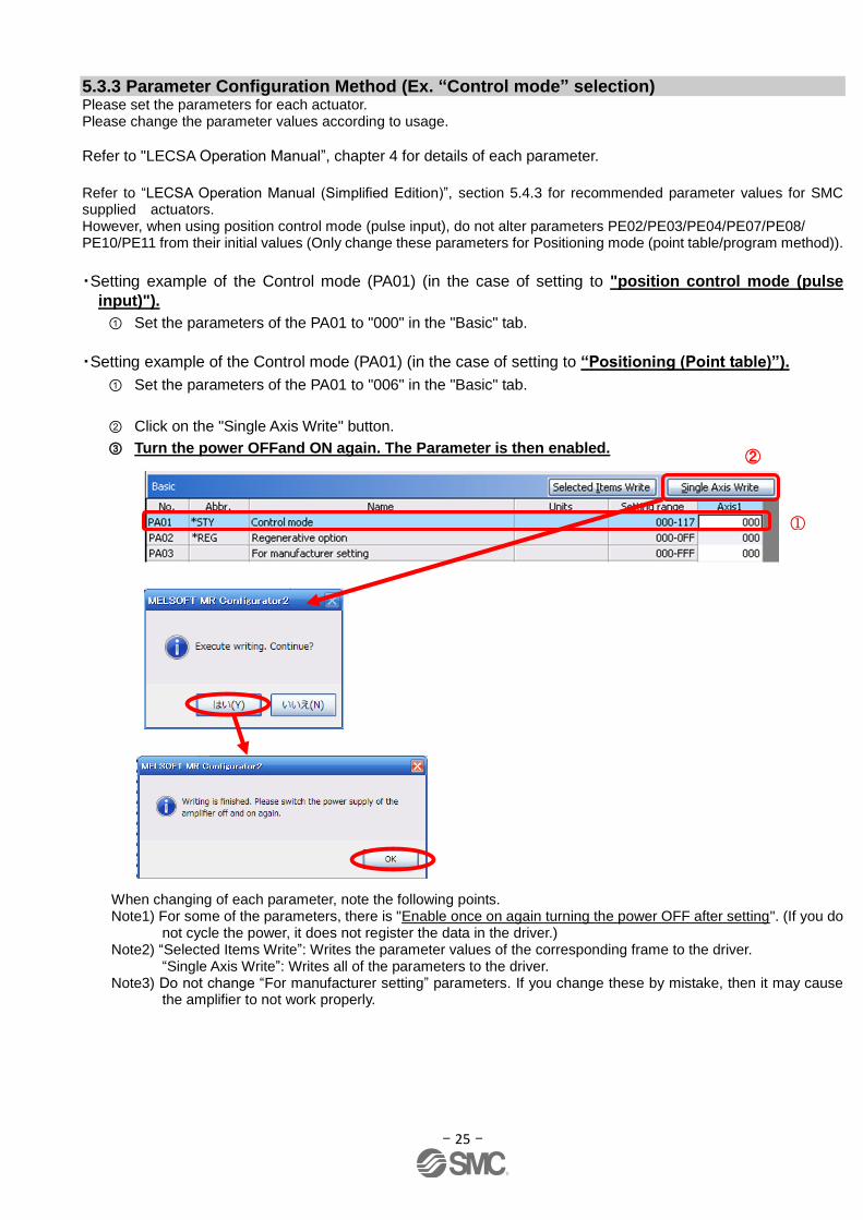
① Set the parameters of the PA01 to "000" in the "Basic" tab.
・Setting example of the Control mode (PA01) (in the case of setting to “Positioning (Point table)”).
① Set the parameters of the PA01 to "006" in the "Basic" tab.
② Click on the "Single Axis Write" button.
③ Turn the power OFFand ON again. The Parameter is then enabled.
When changing of each parameter, note the following points. Note1) For some of the parameters, there is "Enable once on again turning the power OFF after setting". (If you do
not cycle the power, it does not register the data in the driver.) Note2) “Selected Items Write”: Writes the parameter values of the corresponding frame to the driver. “Single Axis Write”: Writes all of the parameters to the driver. Note3) Do not change “For manufacturer setting” parameters. If you change these by mistake, then it may cause
the amplifier to not work properly.
①
②
- 26 -
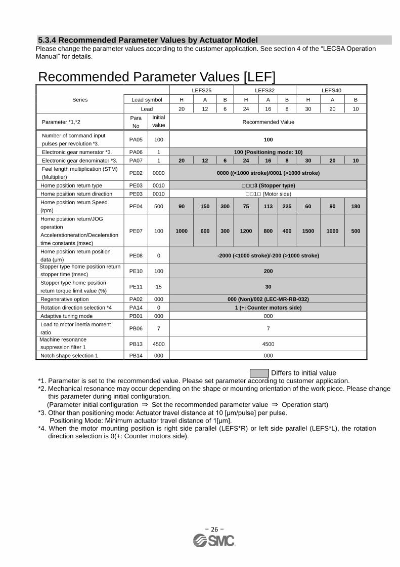
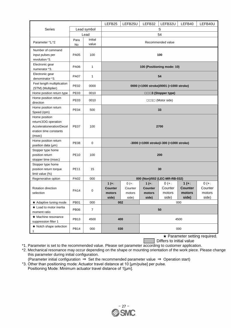
5.3.4 Recommended Parameter Values by Actuator Model Please change the parameter values according to the customer application. See section 4 of the “LECSA Operation Manual” for details.
Recommended Parameter Values [LEF]
Series
LEFS25 LEFS32 LEFS40
Lead symbol H A B H A B H A B
Lead 20 12 6 24 16 8 30 20 10
Parameter *1,*2 Para
No
Initial
value Recommended Value
Number of command input
pulses per revolution *3. PA05 100 100
Electronic gear numerator *3. PA06 1 100 (Positioning mode: 10)
Electronic gear denominator *3. PA07 1 20 12 6 24 16 8 30 20 10
Feel length multiplication (STM)
(Multiplier) PE02 0000 0000 ((<1000 stroke)/0001 (>1000 stroke)
Home position return type PE03 0010 □□□3 (Stopper type)
Home position return direction PE03 0010 □□1□ (Motor side)
Home position return Speed
(rpm) PE04 500 90 150 300 75 113 225 60 90 180
Home position return/JOG
operation
Accelerationeration/Deceleration
time constants (msec)
PE07 100 1000 600 300 1200 800 400 1500 1000 500
Home position return position
data (μm) PE08 0 -2000 (<1000 stroke)/-200 (>1000 stroke)
Stopper type home position return
stopper time (msec) PE10 100 200
Stopper type home position
return torque limit value (%) PE11 15 30
Regenerative option PA02 000 000 (Non)/002 (LEC-MR-RB-032)
Rotation direction selection *4 PA14 0 1 (+:Counter motors side)
Adaptive tuning mode PB01 000 000
Load to motor inertia moment
ratio PB06 7 7
Machine resonance
suppression filter 1 PB13 4500 4500
Notch shape selection 1 PB14 000 000
Differs to initial value
*1. Parameter is set to the recommended value. Please set parameter according to customer application. *2. Mechanical resonance may occur depending on the shape or mounting orientation of the work piece. Please change
this parameter during initial configuration.
(Parameter initial configuration ⇒ Set the recommended parameter value ⇒ Operation start)
*3. Other than positioning mode: Actuator travel distance at 10 [μm/pulse] per pulse. Positioning Mode: Minimum actuator travel distance of 1[μm].
*4. When the motor mounting position is right side parallel (LEFS*R) or left side parallel (LEFS*L), the rotation direction selection is 0(+: Counter motors side).
- 27 -
Series
LEFB25 LEFB25U LEFB32 LEFB32U LEFB40 LEFB40U
Lead symbol S
Lead 54
Parameter *1,*2 Para
No
Initial
value Recommended value
Number of command
input pulses per
revolution *3.
PA05 100 100
Electronic gear
numerator *3. PA06 1 100 (Positioning mode: 10)
Electronic gear
denominator *3. PA07 1 54
Feel length multiplication
(STM) (Multiplier) PE02 0000 0000 (<1000 stroke)/0001 (>1000 stroke)
Home position return type PE03 0010 □□□3 (Stopper type)
Home position return
direction PE03 0010 □□1□ (Motor side)
Home position return
Speed (rpm) PE04 500 33
Home position
return/JOG operation
Accelerationeration/Decel
eration time constants
(msec)
PE07 100 2700
Home position return
position data (μm) PE08 0 -3000 (<1000 stroke)/-300 (>1000 stroke)
Stopper type home
position return
stopper time (msec)
PE10 100 200
Stopper type home
position return torque
limit value (%)
PE11 15 30
Regenerative option PA02 000 000 (Non)/002 (LEC-MR-RB-032)
Rotation direction
selection PA14 0
1 (+:
Counter
motors
side)
0 (+:
Counter
motors
side)
1 (+:
Counter
motors
side)
0 (+:
Counter
motors
side)
1 (+:
Counter
motors
side)
0 (+:
Counter
motors
side)
★ Adaptive tuning mode PB01 000 002 000
★ Load to motor inertia
moment ratio PB06 7 50
★ Machine resonance
suppression filter 1 PB13 4500 400 4500
★ Notch shape selection
1 PB14 000 030 000
★ Parameter setting required. Differs to initial value
*1. Parameter is set to the recommended value. Please set parameter according to customer application. *2. Mechanical resonance may occur depending on the shape or mounting orientation of the work piece. Please change
this parameter during initial configuration.
(Parameter initial configuration ⇒ Set the recommended parameter value ⇒ Operation start)
*3. Other than positioning mode: Actuator travel distance at 10 [μm/pulse] per pulse. Positioning Mode: Minimum actuator travel distance of 1[μm].
- 28 -
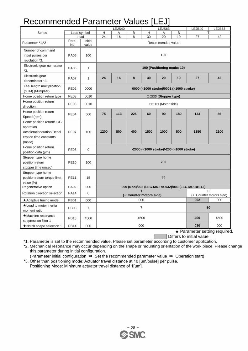
Recommended Parameter Values [LEJ] Series
LEJS40 LEJS63 LEJB40 LEJB63
Lead symbol H A B H A B T
Lead 24 16 8 30 20 10 27 42
Parameter *1,*2 Para. No
Initial value
Recommended value
Number of command
input pulses per
revolution *3.
PA05 100 100
Electronic gear numerator
*3. PA06 1 100 (Positioning mode: 10)
Electronic gear
denominator *3. PA07 1 24 16 8 30 20 10 27 42
Feel length multiplication
(STM) (Multiplier) PE02 0000 0000 (<1000 stroke)/0001 (>1000 stroke)
Home position return type PE03 0010 □□□3 (Stopper type)
Home position return
direction PE03 0010 □□1□ (Motor side)
Home position return
Speed (rpm) PE04 500 75 113 225 60 90 180 133 86
Home position return/JOG
operation
Accelerationeration/Decel
eration time constants
(msec)
PE07 100 1200 800 400 1500 1000 500 1350 2100
Home position return
position data (μm) PE08 0 -2000 (<1000 stroke)/-200 (>1000 stroke)
Stopper type home
position return
stopper time (msec)
PE10 100 200
Stopper type home
position return torque limit
value (%)
PE11 15 30
Regenerative option PA02 000 000 (Non)/002 (LEC-MR-RB-032)/003 (LEC-MR-RB-12)
Rotation direction selection PA14 0 1
(+:Counter motors side)
0
(+:Counter motors side)
★Adaptive tuning mode PB01 000 000 002 000
★Load to motor inertia
moment ratio PB06 7 7 50
★Machine resonance
suppression filter 1 PB13 4500 4500 400 4500
★Notch shape selection 1 PB14 000 000 030 000
★ Parameter setting required. Differs to initial value
*1. Parameter is set to the recommended value. Please set parameter according to customer application. *2. Mechanical resonance may occur depending on the shape or mounting orientation of the work piece. Please change
this parameter during initial configuration.
(Parameter initial configuration ⇒ Set the recommended parameter value ⇒ Operation start)
*3. Other than positioning mode: Actuator travel distance at 10 [μm/pulse] per pulse. Positioning Mode: Minimum actuator travel distance of 1[μm].
- 29 -
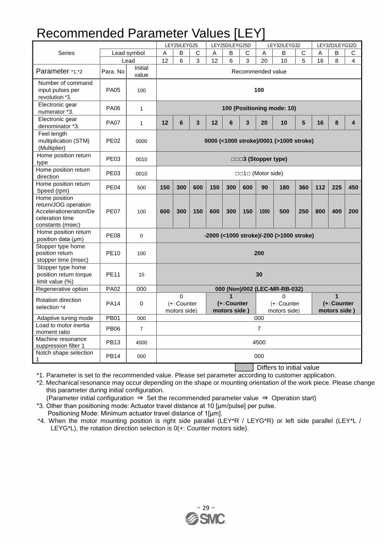
Recommended Parameter Values [LEY]
Series
LEY25/LEYG25 LEY25D/LEYG25D LEY32/LEYG32 LEY32D/LEYG32D
Lead symbol A B C A B C A B C A B C
Lead 12 6 3 12 6 3 20 10 5 16 8 4
Parameter *1,*2 Para. No Initial
value Recommended value
Number of command
input pulses per
revolution *3.
PA05 100 100
Electronic gear
numerator *3. PA06 1 100 (Positioning mode: 10)
Electronic gear
denominator *3. PA07 1 12 6 3 12 6 3 20 10 5 16 8 4
Feel length
multiplication (STM)
(Multiplier)
PE02 0000 0000 (<1000 stroke)/0001 (>1000 stroke)
Home position return
type PE03 0010 □□□3 (Stopper type)
Home position return
direction PE03 0010 □□1□ (Motor side)
Home position return
Speed (rpm) PE04 500 150 300 600 150 300 600 90 180 360 112 225 450
Home position return/JOG operation Accelerationeration/Deceleration time constants (msec)
PE07 100 600 300 150 600 300 150 1000 500 250 800 400 200
Home position return
position data (μm) PE08 0 -2000 (<1000 stroke)/-200 (>1000 stroke)
Stopper type home position return
stopper time (msec) PE10 100 200
Stopper type home
position return torque
limit value (%)
PE11 15 30
Regenerative option PA02 000 000 (Non)/002 (LEC-MR-RB-032)
Rotation direction
selection *4 PA14 0
0
(+:Counter
motors side)
1
(+:Counter
motors side )
0
(+:Counter
motors side)
1
(+:Counter
motors side )
Adaptive tuning mode PB01 000 000
Load to motor inertia moment ratio
PB06 7 7
Machine resonance suppression filter 1
PB13 4500 4500
Notch shape selection 1
PB14 000 000
Differs to initial value *1. Parameter is set to the recommended value. Please set parameter according to customer application. *2. Mechanical resonance may occur depending on the shape or mounting orientation of the work piece. Please change
this parameter during initial configuration.
(Parameter initial configuration ⇒ Set the recommended parameter value ⇒ Operation start)
*3. Other than positioning mode: Actuator travel distance at 10 [μm/pulse] per pulse. Positioning Mode: Minimum actuator travel distance of 1[μm].
*4. When the motor mounting position is right side parallel (LEY*R / LEYG*R) or left side parallel (LEY*L / LEYG*L), the rotation direction selection is 0(+: Counter motors side).
- 30 -
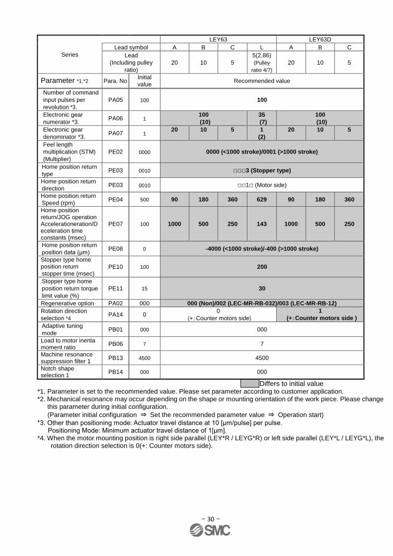
Series
LEY63 LEY63D
Lead symbol A B C L A B C
Lead
(Including pulley
ratio)
20 10 5
5(2.86)
(Pulley
ratio 4/7)
20 10 5
Parameter *1,*2 Para. No Initial
value Recommended value
Number of command
input pulses per
revolution *3.
PA05 100 100
Electronic gear
numerator *3. PA06 1
100
(10)
35
(7)
100
(10)
Electronic gear
denominator *3. PA07 1
20
10
5
1
(2)
20
10
5
Feel length
multiplication (STM)
(Multiplier)
PE02 0000 0000 (<1000 stroke)/0001 (>1000 stroke)
Home position return
type PE03 0010 □□□3 (Stopper type)
Home position return
direction PE03 0010 □□1□ (Motor side)
Home position return
Speed (rpm) PE04 500 90 180 360 629 90 180 360
Home position return/JOG operation Accelerationeration/Deceleration time constants (msec)
PE07 100 1000 500 250 143 1000 500 250
Home position return
position data (μm) PE08 0 -4000 (<1000 stroke)/-400 (>1000 stroke)
Stopper type home position return
stopper time (msec) PE10 100 200
Stopper type home
position return torque
limit value (%)
PE11 15 30
Regenerative option PA02 000 000 (Non)/002 (LEC-MR-RB-032)/003 (LEC-MR-RB-12)
Rotation direction
selection *4 PA14 0
0
(+:Counter motors side)
1
(+:Counter motors side )
Adaptive tuning
mode PB01 000 000
Load to motor inertia moment ratio
PB06 7 7
Machine resonance suppression filter 1
PB13 4500 4500
Notch shape selection 1
PB14 000 000
Differs to initial value *1. Parameter is set to the recommended value. Please set parameter according to customer application. *2. Mechanical resonance may occur depending on the shape or mounting orientation of the work piece. Please change
this parameter during initial configuration.
(Parameter initial configuration ⇒ Set the recommended parameter value ⇒ Operation start)
*3. Other than positioning mode: Actuator travel distance at 10 [μm/pulse] per pulse. Positioning Mode: Minimum actuator travel distance of 1[μm].
*4. When the motor mounting position is right side parallel (LEY*R / LEYG*R) or left side parallel (LEY*L / LEYG*L), the rotation direction selection is 0(+: Counter motors side).
- 31 -
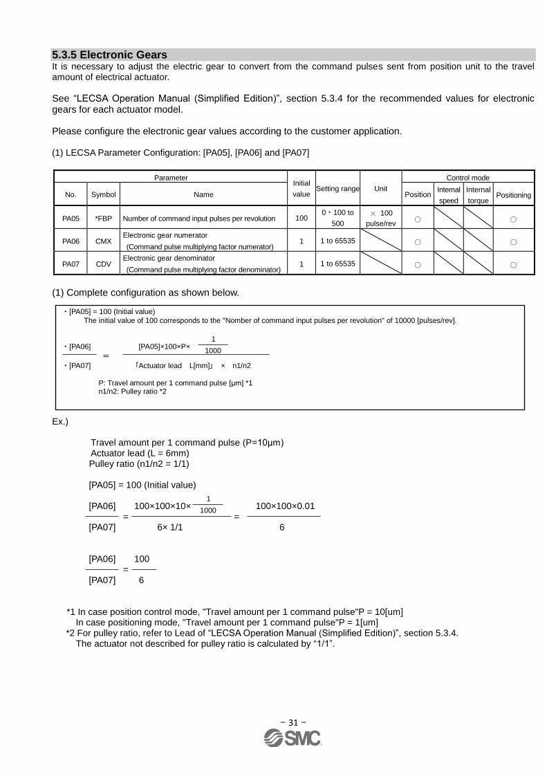
5.3.5 Electronic Gears It is necessary to adjust the electric gear to convert from the command pulses sent from position unit to the travel amount of electrical actuator.
See “LECSA Operation Manual (Simplified Edition)”, section 5.3.4 for the recommended values for electronic gears for each actuator model.
Please configure the electronic gear values according to the customer application. (1) LECSA Parameter Configuration: [PA05], [PA06] and [PA07]
Parameter Initial
value Setting range Unit
Control mode
No. Symbol Name Position Internal
speed
Internal
torque Positioning
PA05 *FBP Number of command input pulses per revolution 100 0 100 to
500
100
pulse/rev
PA06 CMX Electronic gear numerator
(Command pulse multiplying factor numerator) 1 1 to 65535
PA07 CDV Electronic gear denominator
(Command pulse multiplying factor denominator) 1 1 to 65535
(1) Complete configuration as shown below.
Ex.) Travel amount per 1 command pulse (P=10μm) Actuator lead (L = 6mm) Pulley ratio (n1/n2 = 1/1)
[PA05] = 100 (Initial value)
[PA06] 100×100×10× 100×100×0.01 = = [PA07] 6× 1/1 6
[PA06] 100 = [PA07] 6
*1 In case position control mode, "Travel amount per 1 command pulse"P = 10[um] In case positioning mode, "Travel amount per 1 command pulse"P = 1[um]
*2 For pulley ratio, refer to Lead of “LECSA Operation Manual (Simplified Edition)”, section 5.3.4. The actuator not described for pulley ratio is calculated by “1/1”.
・[PA05] = 100 (Initial value)
The initial value of 100 corresponds to the "Nomber of command input pulses per revolution" of 10000 [pulses/rev].
・[PA06] [PA05]×100×P×
=
・[PA07] 「Actuator lead L[mm]」 × n1/n2
P: Travel amount per 1 command pulse [μm] *1 n1/n2: Pulley ratio *2
1000
1
1000
1

- 32 -
5.3.6 Control mode selection
① To use position control mode (pulse input), navigate to the "Basic" tab of the "Parameter Setting" screen - "Control mode selection" - Please select "Position control mode". (“PA01” parameter in the "Basic" tab of the List display also changes to "000".) To use positioning mode (point table), navigate to the "Basic" tab of the "Parameter Setting" screen - "Control mode selection" - Please select "Positioning mode method". (“PA01” parameter in the "Basic" tab of the List display also changes to "006".)
② Click on the "Single Axis Write" button.
③ Click OK.
④ Click OK. (After power OFF→ON, the parameter is enabled.)
①
②
③ ④
- 33 -
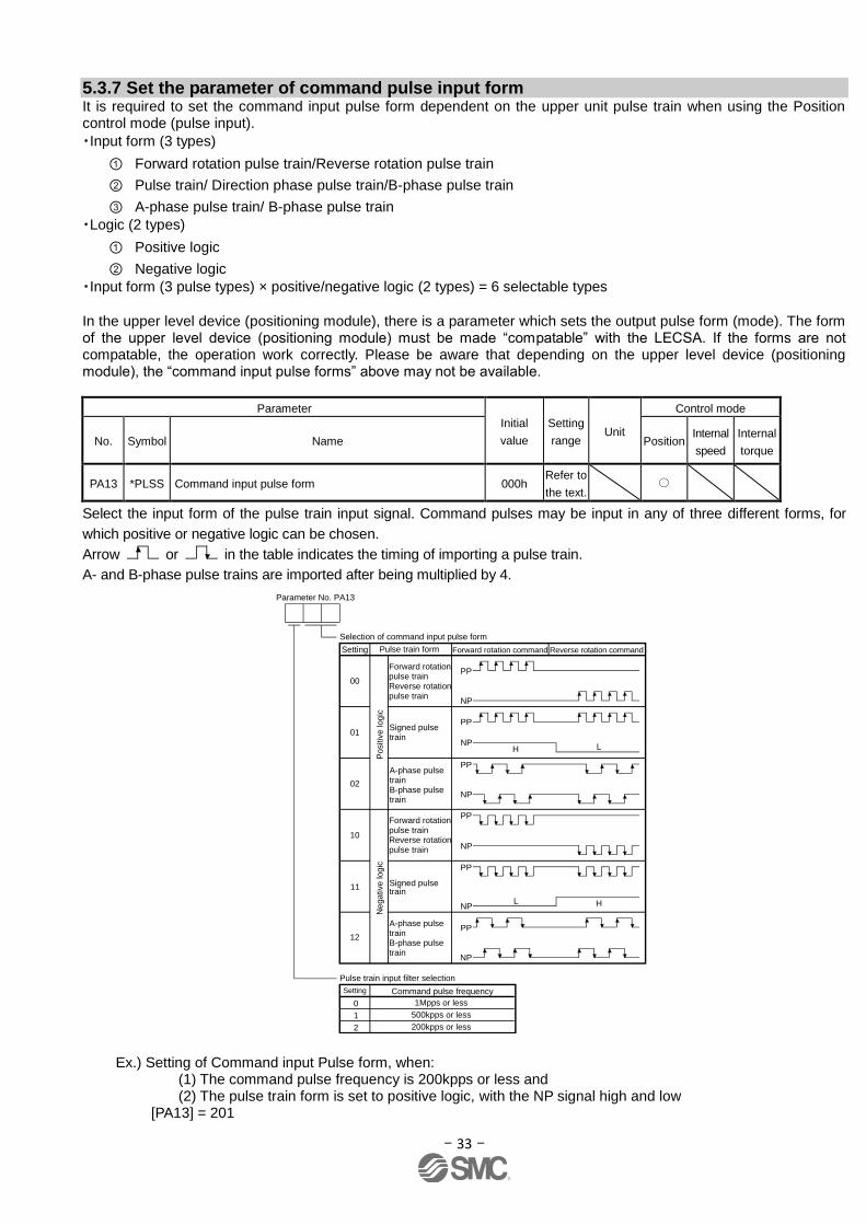
5.3.7 Set the parameter of command pulse input form It is required to set the command input pulse form dependent on the upper unit pulse train when using the Position control mode (pulse input).
・Input form (3 types)
① Forward rotation pulse train/Reverse rotation pulse train
② Pulse train/ Direction phase pulse train/B-phase pulse train
③ A-phase pulse train/ B-phase pulse train
・Logic (2 types)
① Positive logic
② Negative logic
・Input form (3 pulse types) × positive/negative logic (2 types) = 6 selectable types
In the upper level device (positioning module), there is a parameter which sets the output pulse form (mode). The form of the upper level device (positioning module) must be made “compatable” with the LECSA. If the forms are not compatable, the operation work correctly. Please be aware that depending on the upper level device (positioning module), the “command input pulse forms” above may not be available.
Parameter
Initial
value
Setting
range Unit
Control mode
No. Symbol Name Position Internal
speed
Internal
torque
PA13 *PLSS Command input pulse form 000h Refer to
the text.
Select the input form of the pulse train input signal. Command pulses may be input in any of three different forms, for
which positive or negative logic can be chosen.
Arrow or in the table indicates the timing of importing a pulse train.
A- and B-phase pulse trains are imported after being multiplied by 4.
Signed pulse train
Forward rotation pulse trainReverse rotation pulse train
Selection of command input pulse form
Parameter No. PA13
Setting
00
01
Pulse train input filter selection
Pulse train form Forward rotation command Reverse rotation command
Signed pulse train
A-phase pulse trainB-phase pulse train
Forward rotation pulse trainReverse rotation pulse train
A-phase pulse trainB-phase pulse train
02
10
12
Po
sitiv
e log
ic
NP
PP
PP
L HNP
PP
NP
NP
PP
LH
PP
NP
PP
NP
Setting
0 1Mpps or less
1 500kpps or less
2 200kpps or less
Ne
ga
tive
lo
gic
11
Command pulse frequency
Ex.) Setting of Command input Pulse form, when: (1) The command pulse frequency is 200kpps or less and (2) The pulse train form is set to positive logic, with the NP signal high and low [PA13] = 201
- 34 -
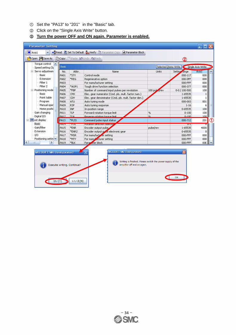
① Set the "PA13" to "201" in the "Basic" tab.
② Click on the "Single Axis Write" button.
③ Turn the power OFF and ON again. Parameter is enabled.
①
②
- 35 -
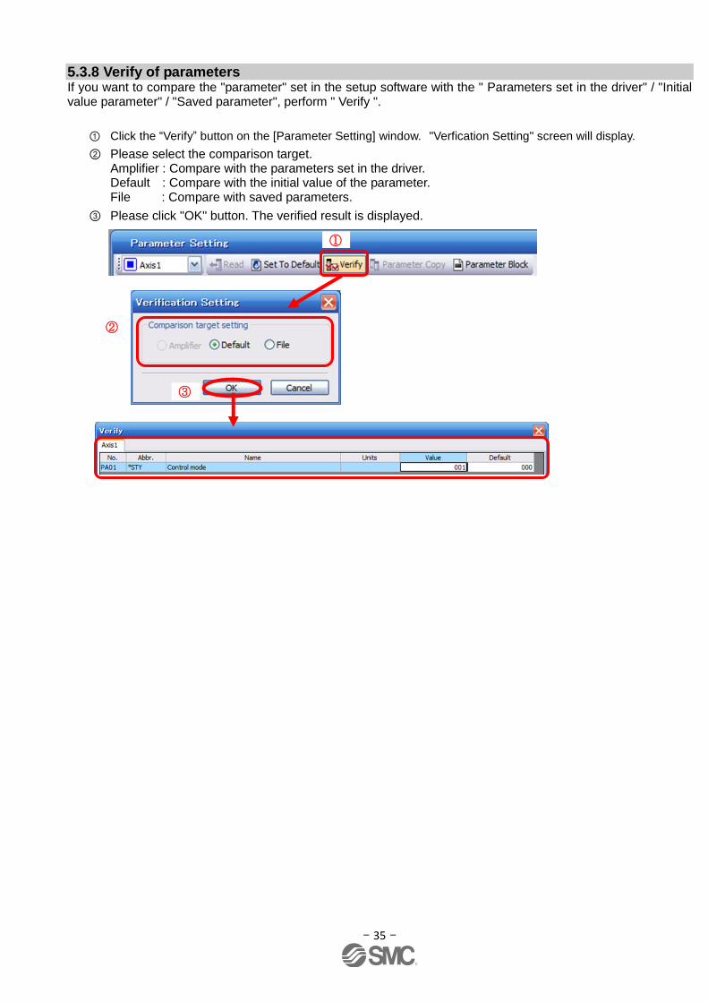
5.3.8 Verify of parameters If you want to compare the "parameter" set in the setup software with the " Parameters set in the driver" / "Initial value parameter" / "Saved parameter", perform " Verify ".
① Click the “Verify” button on the [Parameter Setting] window. "Verfication Setting" screen will display.
② Please select the comparison target. Amplifier : Compare with the parameters set in the driver. Default : Compare with the initial value of the parameter. File : Compare with saved parameters.
③ Please click "OK" button. The verified result is displayed.
①
②
③
- 36 -
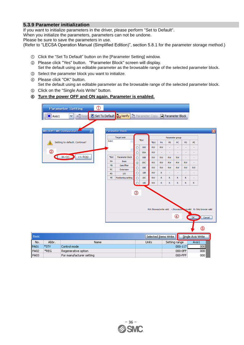
5.3.9 Parameter initialization If you want to initialize parameters in the driver, please perform "Set to Default". When you initialize the parameters, parameters can not be undone. Please be sure to save the parameters in use. (Refer to “LECSA Operation Manual (Simplified Edition)”, section 5.8.1 for the parameter storage method.)
① Click the “Set To Default” button on the [Parameter Setting] window.
② Please click "Yes" button. "Parameter Block" screen will display. Set the default using an editable parameter as the browsable range of the selected parameter block.
③ Select the parameter block you want to initialize.
④ Please click "OK" button. Set the default using an editable parameter as the browsable range of the selected parameter block.
⑤ Click on the "Single Axis Write" button.
⑥ Turn the power OFF and ON again. Parameter is enabled.
②
③
④
⑤
①

- 37 -
5.4 JOG Mode in the Setup Software
① T The “JOG Mode” window can be displayed by selecting “Jog Mode” from the “Test Mode” menu in the setup software.
② Click “OK”. (When using this function, all external input signal operation will be diabled. If controlling using a PLC or other upper device, please turn off the power and reset the device before use.)
①
②
①
②
- 38 -
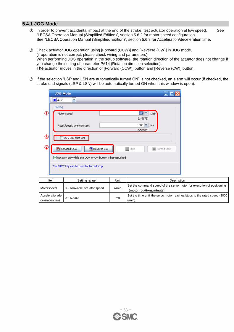
5.4.1 JOG Mode
① In order to prevent accidental impact at the end of the stroke, test actuator operation at low speed. See “LECSA Operation Manual (Simplified Edition)”, section 5.6.2 for motor speed configuration. See “LECSA Operation Manual (Simplified Edition)”, section 5.6.3 for Acceleration/deceleration time.
② Check actuator JOG operation using [Forward (CCW)] and [Reverse (CW)] in JOG mode. (if operation is not correct, please check wiring and parameters). When performing JOG operation in the setup software, the rotation direction of the actuator does not change if you change the setting of parameter PA14 (Rotation direction selection). The actuator moves in the direction of [Forward (CCW)] button and [Reverse (CW)] button.
③ If the selection “LSP and LSN are automatically turned ON” is not checked, an alarm will occur (if checked, the stroke end signals (LSP & LSN) will be automatically turned ON when this window is open).
Item Setting range Unit Description
Motorspeed 0 ~ allowable actuator speed r/min Set the command speed of the servo motor for execution of positioning
(motor rotations/minute).
Acceleration/de
celeration time 0 ~ 50000 ms
Set the time until the servo motor reaches/stops to the rated speed (3000
r/min).
①
③
②
- 39 -
5.5 Changing I/O Signal Allocation Input/output signal assignment can be changed as appropriate from initial settings. There may be cases when changes to the Input/output signal assignment are required for actuator operation.
Please be aware that any changes will alter signals entered as initial settings. Please allocate it according to your system specification. *When configuring PD**, please set parameter write inhibit [PA19] to 00E. See “LECSA Operation Manual”, section 4.4 for details. Set parameters related to I/O: [PD02] to [PD18]
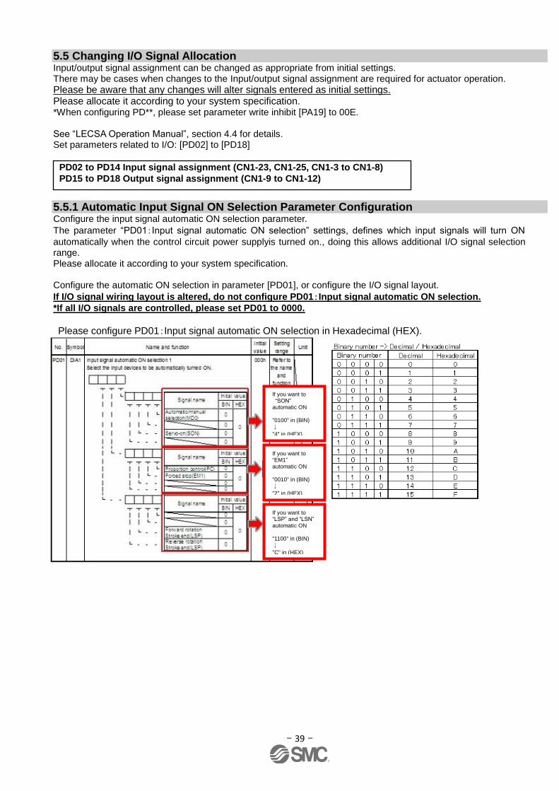
5.5.1 Automatic Input Signal ON Selection Parameter Configuration Configure the input signal automatic ON selection parameter.
The parameter “PD01:Input signal automatic ON selection” settings, defines which input signals will turn ON
automatically when the control circuit power supplyis turned on., doing this allows additional I/O signal selection range. Please allocate it according to your system specification.
Configure the automatic ON selection in parameter [PD01], or configure the I/O signal layout.
If I/O signal wiring layout is altered, do not configure PD01:Input signal automatic ON selection.
*If all I/O signals are controlled, please set PD01 to 0000.
Please configure PD01:Input signal automatic ON selection in Hexadecimal (HEX).
If you want to “SON” automatic ON "0100" in (BIN)
↓
"4" in (HEX)
If you want to “EM1” automatic ON "0010" in (BIN)
↓
"2" in (HEX)
If you want to “LSP” and “LSN” automatic ON "1100" in (BIN)
↓
"C" in (HEX)
PD02 to PD14 Input signal assignment (CN1-23, CN1-25, CN1-3 to CN1-8)
PD15 to PD18 Output signal assignment (CN1-9 to CN1-12)

- 40 -
During Actuator Operation: <Signals which must be ON during actuator operation>
Set PD01 as 0C24. The following signals will automatically turn on when power supply turns on. SON Servo-on OFF:Servo-off
ON :Servo-on (operational)
LSP Forward rotaion Stroke end (normally closed contact)
OFF: Forward rotaion Stroke end
ON :Forward rotaion Stroke end off (operational)
LSN Reverse rotaion Stroke end (normally closed contact)
OFF:Reverse rotaion Stroke end
ON :Reverse rotaion Stroke end off (operational)
EM1 Forced stop (normally closed contact)
OFF:Forced stop
ON :Forced stop off (operational)
In positioning mode (point table), congifure the operation mode using automatic/manual selection MD0.
The MD0 off selection will allow Jog operation and it will require an input reserved for MD0. For Automatic MD0 please set PD01 as 0C25. Will also include MD0 automatic ON. MD0 Automatic/manual selection OFF: Manual Operation Mode
JOG operation available. ON: Automatic Operation Mode Home position return/positioning mode operation available.
* Enabling “Stroke end” (LSP, LSN) , “Forced stop” (EM1) and “Servo-on” (SON) Signals
① Set to PD01 to 0C24 in the I/O tab.
② Click on the "Single Axis Write" button.
③ Cycle the power off, then for the changed Parameters to be enabled. * In this configuration, the stroke end (LSP, LSN), forced stop (EM1) and servo-on (SON) signals will be ON automatically when the power is turned ON.
①
②
- 41 -
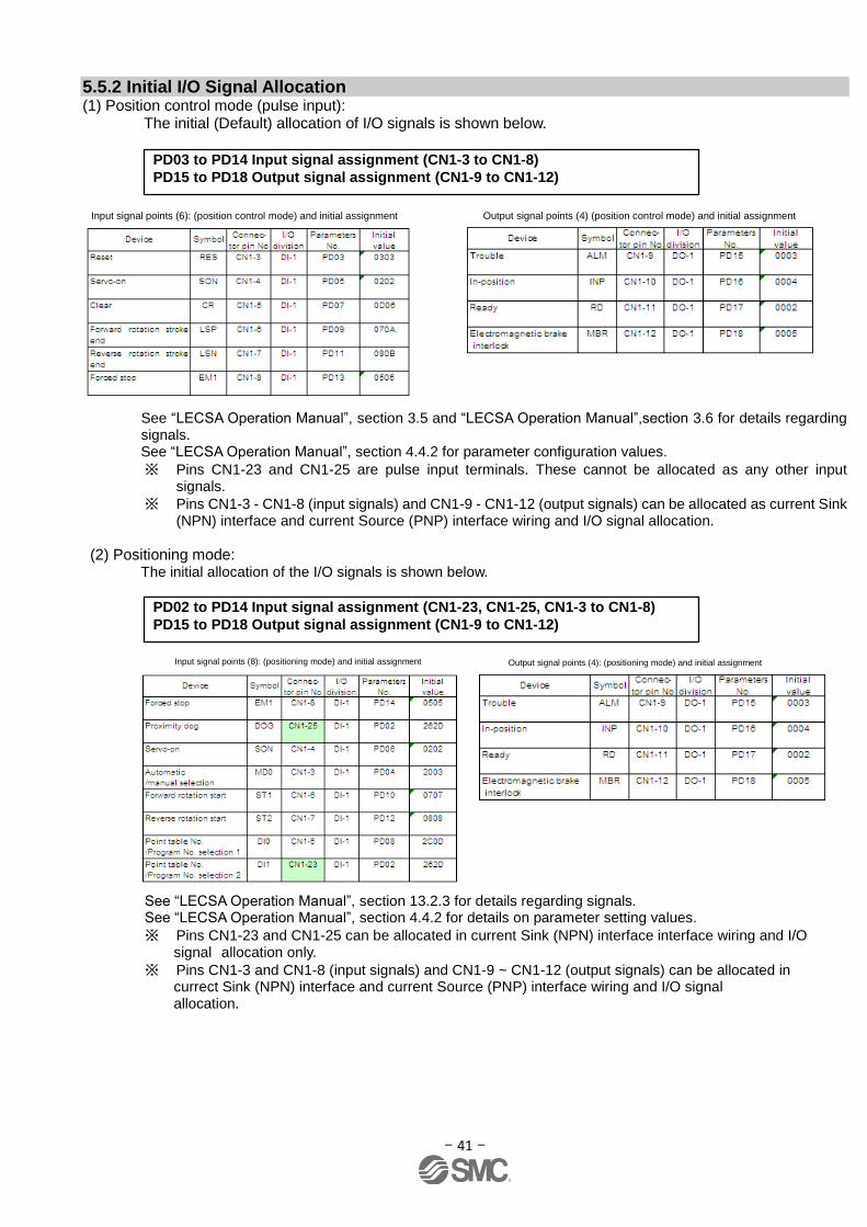
5.5.2 Initial I/O Signal Allocation (1) Position control mode (pulse input):
The initial (Default) allocation of I/O signals is shown below.
See “LECSA Operation Manual”, section 3.5 and “LECSA Operation Manual”,section 3.6 for details regarding signals. See “LECSA Operation Manual”, section 4.4.2 for parameter configuration values.
※ Pins CN1-23 and CN1-25 are pulse input terminals. These cannot be allocated as any other input signals.
※ Pins CN1-3 - CN1-8 (input signals) and CN1-9 - CN1-12 (output signals) can be allocated as current Sink (NPN) interface and current Source (PNP) interface wiring and I/O signal allocation.
(2) Positioning mode: The initial allocation of the I/O signals is shown below.
See “LECSA Operation Manual”, section 13.2.3 for details regarding signals. See “LECSA Operation Manual”, section 4.4.2 for details on parameter setting values.
※ Pins CN1-23 and CN1-25 can be allocated in current Sink (NPN) interface interface wiring and I/O signal allocation only.
※ Pins CN1-3 and CN1-8 (input signals) and CN1-9 ~ CN1-12 (output signals) can be allocated in currect Sink (NPN) interface and current Source (PNP) interface wiring and I/O signal allocation.
PD02 to PD14 Input signal assignment (CN1-23, CN1-25, CN1-3 to CN1-8)
PD15 to PD18 Output signal assignment (CN1-9 to CN1-12)
Input signal points (6): (position control mode) and initial assignment Output signal points (4) (position control mode) and initial assignment
Input signal points (8): (positioning mode) and initial assignment Output signal points (4): (positioning mode) and initial assignment
PD03 to PD14 Input signal assignment (CN1-3 to CN1-8)
PD15 to PD18 Output signal assignment (CN1-9 to CN1-12)
- 42 -
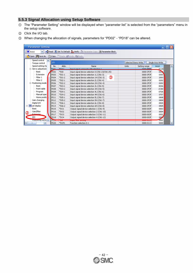
5.5.3 Signal Allocation using Setup Software
① The “Parameter Setting” window will be displayed when “parameter list” is selected from the “parameters” menu in the setup software.
② Click the I/O tab.
③ When changing the allocation of signals, parameters for “PD02” - “PD18” can be altered.
③
②
- 43 -
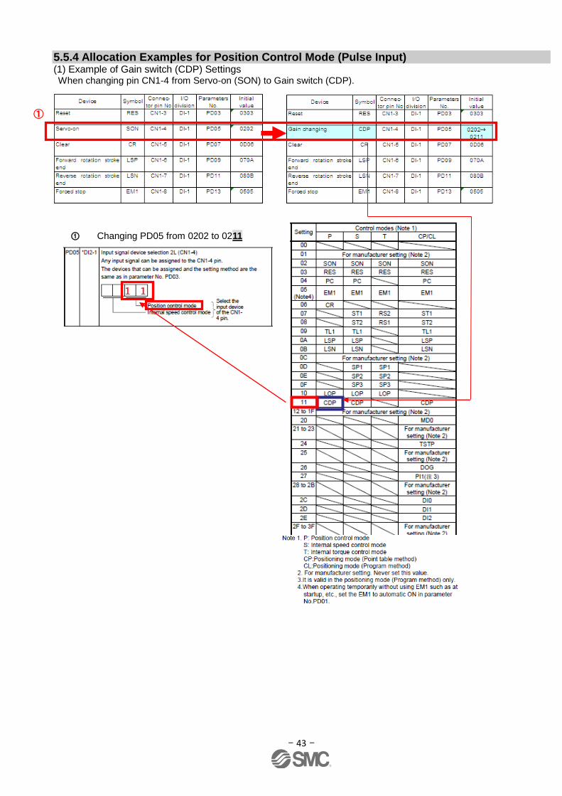
5.5.4 Allocation Examples for Position Control Mode (Pulse Input) (1) Example of Gain switch (CDP) Settings When changing pin CN1-4 from Servo-on (SON) to Gain switch (CDP).
① Changing PD05 from 0202 to 0211
①
1 1
- 44 -
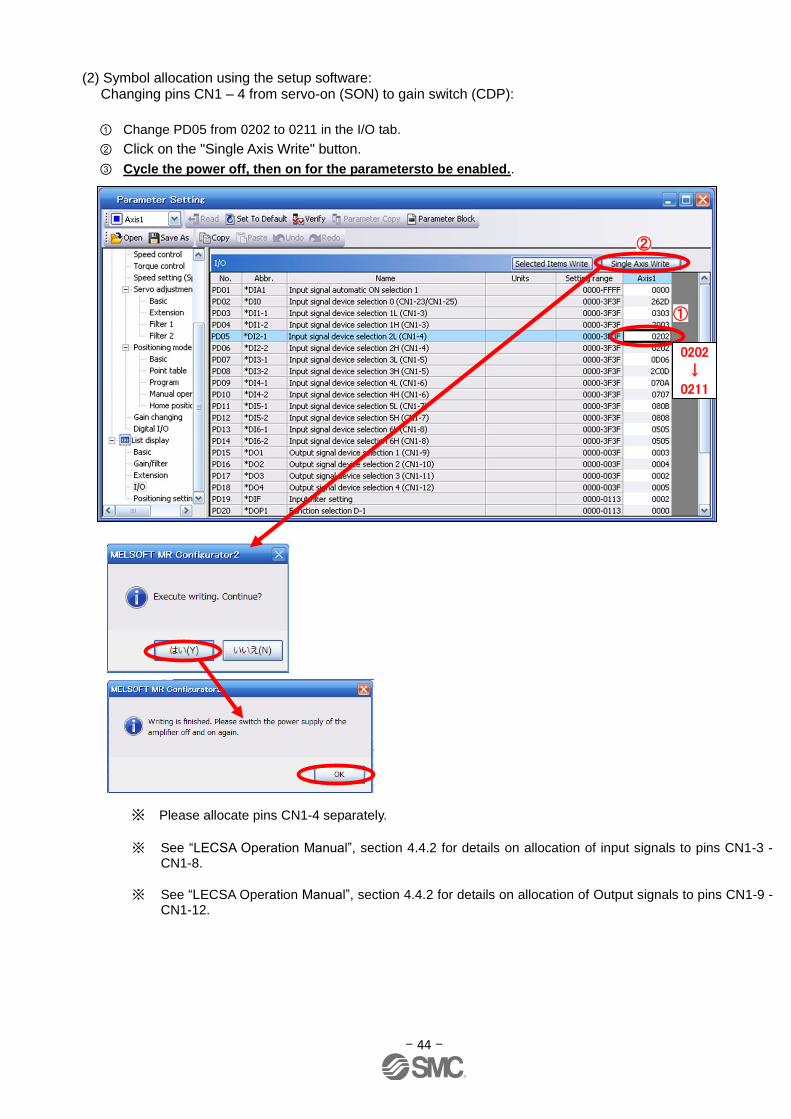
(2) Symbol allocation using the setup software: Changing pins CN1 – 4 from servo-on (SON) to gain switch (CDP):
① Change PD05 from 0202 to 0211 in the I/O tab.
② Click on the "Single Axis Write" button.
③ Cycle the power off, then on for the parametersto be enabled..
※ Please allocate pins CN1-4 separately.
※ See “LECSA Operation Manual”, section 4.4.2 for details on allocation of input signals to pins CN1-3 - CN1-8.
※ See “LECSA Operation Manual”, section 4.4.2 for details on allocation of Output signals to pins CN1-9 - CN1-12.
②
①
0202
↓
0211
- 45 -
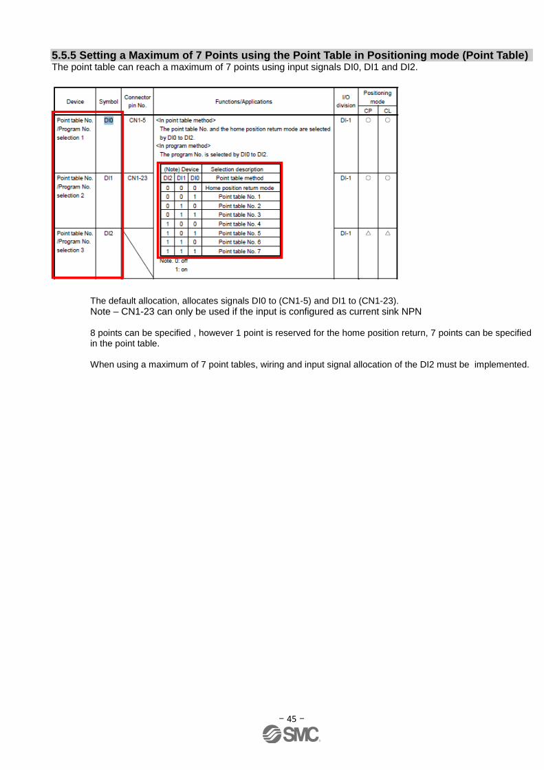
5.5.5 Setting a Maximum of 7 Points using the Point Table in Positioning mode (Point Table) The point table can reach a maximum of 7 points using input signals DI0, DI1 and DI2.
The default allocation, allocates signals DI0 to (CN1-5) and DI1 to (CN1-23).
Note – CN1-23 can only be used if the input is configured as current sink NPN 8 points can be specified , however 1 point is reserved for the home position return, 7 points can be specified in the point table.
When using a maximum of 7 point tables, wiring and input signal allocation of the DI2 must be implemented.
- 46 -
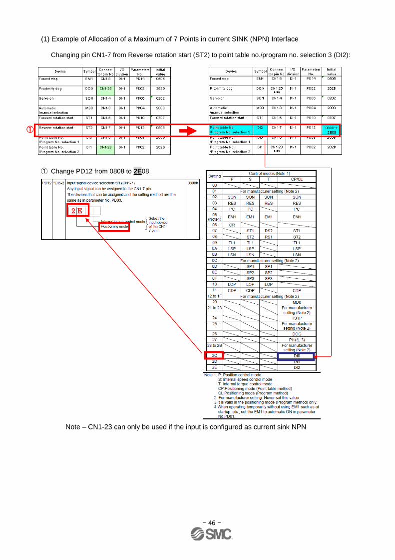
(1) Example of Allocation of a Maximum of 7 Points in current SINK (NPN) Interface
Changing pin CN1-7 from Reverse rotation start (ST2) to point table no./program no. selection 3 (DI2):
① Change PD12 from 0808 to 2E08.
Note – CN1-23 can only be used if the input is configured as current sink NPN
①
2 E
- 47 -
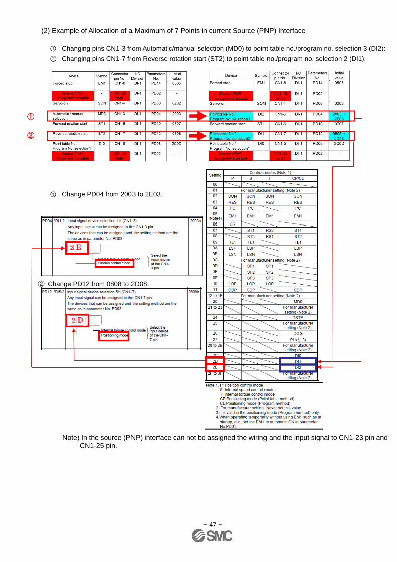
(2) Example of Allocation of a Maximum of 7 Points in current Source (PNP) Interface
① Changing pins CN1-3 from Automatic/manual selection (MD0) to point table no./program no. selection 3 (DI2):
② Changing pins CN1-7 from Reverse rotation start (ST2) to point table no./program no. selection 2 (DI1):
① Change PD04 from 2003 to 2E03.
② Change PD12 from 0808 to 2D08.
Note) In the source (PNP) interface can not be assigned the wiring and the input signal to CN1-23 pin and CN1-25 pin.
2 D
①
②
2 E

- 48 -
(3) Example of Signal Allocation using the setup software
When changing pins CN1-7 from Reverse rotation start (ST2) to point table no./program no. selection 3 (DI2):
① Change PD12 from 0808 to 2E08 in the I/O tab.
② Click on the "Single Axis Write" button.
③ Cycle the power off, and then on for the parameters to be enabled.
* Complete pin CN1-7 allocation separately.
* See “LECSA Operation Manual”,section 4.4.2 for details on allocation of input signals to pins CN1-3 - CN1-8
* See “LECSA Operation Manual”,section 4.4.2 for details on allocation of input signals to pins CN1-23 and CN1-25
* See “LECSA Operation Manual”,section 4.4.2 for details on allocation of output signals to pins CN1-9 and CN1-12
Schematics showing typical 3 point positioning
0808
↓
2E08
②
①

- 49 -
5.5.6 I/O Signal Allocation Check The ON/OFF state (including layout check) and signal names allocated to CN1 can be checked. When parameters for PD02 - PD18 have been changed, It is necessary to confirm these are correctly assigned.
① From the Monitor menu of the Setup Software select I/O Monitor. The I/O Monitor window opens and displays the inputs and outputs that are applicable. The window also displays the applicable MODE. The highlighted background implies the signals are active.
Positioning mode (point table)
①
- 50 -
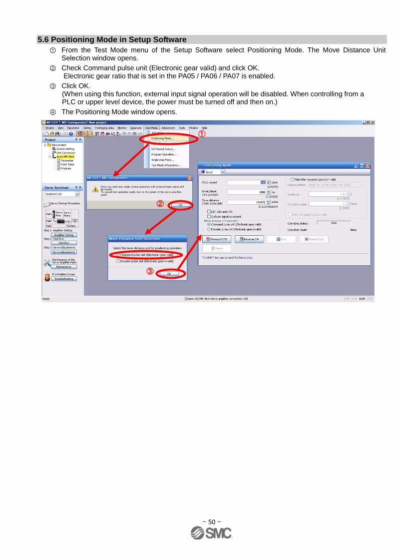
5.6 Positioning Mode in Setup Software
① From the Test Mode menu of the Setup Software select Positioning Mode. The Move Distance Unit Selection window opens.
② Check Command pulse unit (Electronic gear valid) and click OK. Electronic gear ratio that is set in the PA05 / PA06 / PA07 is enabled.
③ Click OK. (When using this function, external input signal operation will be disabled. When controlling from a PLC or upper level device, the power must be turned off and then on.)
④ The Positioning Mode window opens.
①
②
③
- 51 -
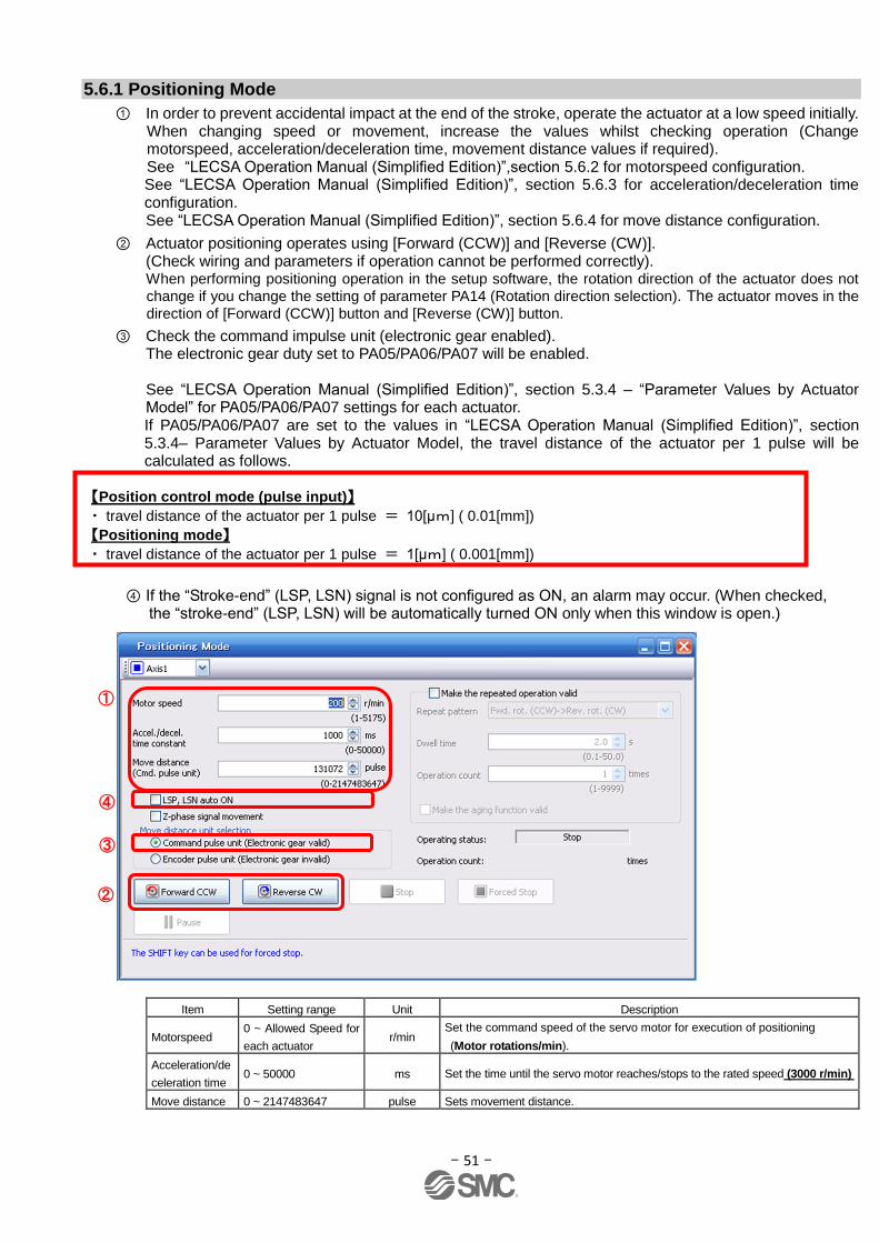
5.6.1 Positioning Mode
① In order to prevent accidental impact at the end of the stroke, operate the actuator at a low speed initially. When changing speed or movement, increase the values whilst checking operation (Change motorspeed, acceleration/deceleration time, movement distance values if required). See “LECSA Operation Manual (Simplified Edition)”,section 5.6.2 for motorspeed configuration.
See “LECSA Operation Manual (Simplified Edition)”, section 5.6.3 for acceleration/deceleration time configuration.
See “LECSA Operation Manual (Simplified Edition)”, section 5.6.4 for move distance configuration.
② Actuator positioning operates using [Forward (CCW)] and [Reverse (CW)]. (Check wiring and parameters if operation cannot be performed correctly). When performing positioning operation in the setup software, the rotation direction of the actuator does not
change if you change the setting of parameter PA14 (Rotation direction selection). The actuator moves in the
direction of [Forward (CCW)] button and [Reverse (CW)] button.
③ Check the command impulse unit (electronic gear enabled). The electronic gear duty set to PA05/PA06/PA07 will be enabled.
See “LECSA Operation Manual (Simplified Edition)”, section 5.3.4 – “Parameter Values by Actuator Model” for PA05/PA06/PA07 settings for each actuator. If PA05/PA06/PA07 are set to the values in “LECSA Operation Manual (Simplified Edition)”, section 5.3.4– Parameter Values by Actuator Model, the travel distance of the actuator per 1 pulse will be calculated as follows.
【Position control mode (pulse input)】
・ travel distance of the actuator per 1 pulse = 10[μm] ( 0.01[mm])
【Positioning mode】
・ travel distance of the actuator per 1 pulse = 1[μm] ( 0.001[mm])
④ If the “Stroke-end” (LSP, LSN) signal is not configured as ON, an alarm may occur. (When checked, the “stroke-end” (LSP, LSN) will be automatically turned ON only when this window is open.)
Item Setting range Unit Description
Motorspeed 0 ~ Allowed Speed for
each actuator r/min
Set the command speed of the servo motor for execution of positioning
(Motor rotations/min).
Acceleration/de
celeration time 0 ~ 50000 ms Set the time until the servo motor reaches/stops to the rated speed (3000 r/min)
Move distance 0 ~ 2147483647 pulse Sets movement distance.
①
②
③
④
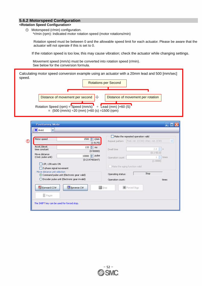
- 52 -
5.6.2 Motorspeed Configuration <Rotation Speed Configuration>
① Motorspeed (r/min) configuration. *r/min (rpm): Indicated motor rotation speed (motor rotations/min)
Rotation speed must be between 0 and the allowable speed limit for each actuator. Please be aware that the actuator will not operate if this is set to 0.
If the rotation speed is too low, this may cause vibration; check the actuator while changing settings.
Movement speed (mm/s) must be converted into rotation speed (r/min). See below for the conversion formula.
Calculating motor speed conversion example using an actuator with a 20mm lead and 500 [mm/sec] speed.
Rotation Speed (rpm) = Speed (mm/s) ÷ Lead (mm) }×60 (S) = {500 (mm/s) ÷20 (mm) }×60 (s) =1500 (rpm)
Distance of movement per second
Distance of movement per rotation
Rotations per Second
÷
①

- 53 -
5.6.3 Acceleration/deceleration Time Configuation < Acceleration/deceleration Time Configuration>
① Acceleration/deceleration time (ms) configuration: The acceleration/deceleration time sets the amount of time (ms) in which a prescribed number of rotations (3000[r/min]) is reached. The acceleration/deceleration time must be set to a value between 0 and the allowable acceleration/deceleration speed for each actuator.
The acceleration/deceleration time must be converted from the acceleration/deceleration speed. See below for the conversion formula.
Calculating Acceleration/deceleration conversion example using an actuator with a 8 [mm] lead with an acceleration of 3000[mm/sec2]. Acceleration/deceleration time (ms) = {3000 (r/min) ÷60 (S) } × 8 (mm) × 1000 3000 (mm/s2)
= 133 (ms)
Accel/decel time (ms) = {Rated Rotation Speed (r/min) ÷60 (S) }× Screw Lead (mm) × 1000 * Note) Acceleration/deceleration speed (mm/s2) *Acceleration speed is measured in ms, so this must be calculated as (s) ×1000
Speed at a rated motor rotation of 3000rpm
①
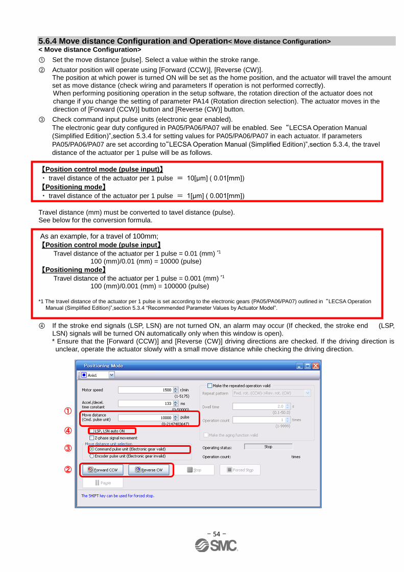
- 54 -
5.6.4 Move distance Configuration and Operation< Move distance Configuration>
< Move distance Configuration>
① Set the move distance [pulse]. Select a value within the stroke range.
② Actuator position will operate using [Forward (CCW)], [Reverse (CW)]. The position at which power is turned ON will be set as the home position, and the actuator will travel the amount set as move distance (check wiring and parameters If operation is not performed correctly). When performing positioning operation in the setup software, the rotation direction of the actuator does not
change if you change the setting of parameter PA14 (Rotation direction selection). The actuator moves in the
direction of [Forward (CCW)] button and [Reverse (CW)] button.
③ Check command input pulse units (electronic gear enabled).
The electronic gear duty configured in PA05/PA06/PA07 will be enabled. See “LECSA Operation Manual
(Simplified Edition)”,section 5.3.4 for setting values for PA05/PA06/PA07 in each actuator. If parameters
PA05/PA06/PA07 are set according to“LECSA Operation Manual (Simplified Edition)”,section 5.3.4, the travel
distance of the actuator per 1 pulse will be as follows.
【Position control mode (pulse input)】
・ travel distance of the actuator per 1 pulse = 10[μm] ( 0.01[mm])
【Positioning mode】
・ travel distance of the actuator per 1 pulse = 1[μm] ( 0.001[mm])
Travel distance (mm) must be converted to tavel distance (pulse). See below for the conversion formula.
As an example, for a travel of 100mm;
【Position control mode (pulse input】
Travel distance of the actuator per 1 pulse = 0.01 (mm) *1 100 (mm)/0.01 (mm) = 10000 (pulse)
【Positioning mode】
Travel distance of the actuator per 1 pulse = 0.001 (mm) *1 100 (mm)/0.001 (mm) = 100000 (pulse)
*1 The travel distance of the actuator per 1 pulse is set according to the electronic gears (PA05/PA06/PA07) outlined in “LECSA Operation
Manual (Simplified Edition)”,section 5.3.4 “Recommended Parameter Values by Actuator Model”.
④ If the stroke end signals (LSP, LSN) are not turned ON, an alarm may occur (If checked, the stroke end (LSP, LSN) signals will be turned ON automatically only when this window is open). * Ensure that the [Forward (CCW)] and [Reverse (CW)] driving directions are checked. If the driving direction is unclear, operate the actuator slowly with a small move distance while checking the driving direction.
①
②
③
④
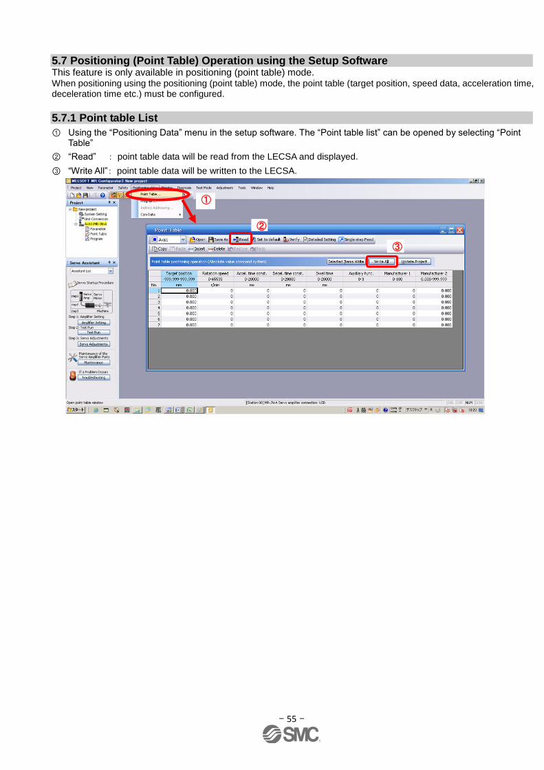
- 55 -
5.7 Positioning (Point Table) Operation using the Setup Software This feature is only available in positioning (point table) mode. When positioning using the positioning (point table) mode, the point table (target position, speed data, acceleration time, deceleration time etc.) must be configured.
5.7.1 Point table List
① Using the “Positioning Data” menu in the setup software. The “Point table list” can be opened by selecting “Point Table”
② “Read” : point table data will be read from the LECSA and displayed.
③ “Write All”: point table data will be written to the LECSA.
①
②
③

- 56 -
5.7.2 Point Table Data
By parameters "PE01:Command mode selection” settings, registration method of data of the point table is
different.
(1) If the parameter " PE01:Command mode selection " setting is "0000:Absolute value command system " .
Item Setting range Unit Description
Target position -999.999
~ 999.999 ×10STM
mm
(1) When using this point table as absolute value command system, set the target address (absolute value).
(2) When using this point table as incremental value command system, set the travel distance. A "-" sign indicates a reverse rotation command.
Number of decimal places changes according to STM (Feel length multiplication)
Rotation speed 0 ~ allowable actuator speed
r/min Sets the command rotation speed (Motor rotations/min) when positioning is executed.
Acceleration time constant
0 ~ 20000 ms Set the time until the servo motor reaches to the rated speed. (3000 r/min)
Deceleration time constant
0 ~ 20000 ms Set the time until the servo motor stops from the rated speed. (3000 r/min
Dwell 0 ~ 20000 ms
When dwell is set and the set dwell has passed after the position command of the selected point table is completed, the position command of the next point table is started. Set "0" in the auxiliary function to make the dwell invalid. Set "1" in the auxiliary function and 0 in the dwell to perform varied speed operation.
Auxiliary function 0 ~ 3
(1) When using this point table in the absolute value command system 0: Automatic operation is performed in accordance with a single point table chosen. 1: Operation is performed in accordance with consecutive point tables without a stop.
(2) When using this point table in the incremental value command system
2: Automatic operation is performed in accordance with a single point table chosen. 3: Operation is performed in accordance with consecutive point tables without a stop.
When a different rotation direction is set, smoothing zero (command output) is confirmed and the rotation direction is then reversed. Setting "1" in point table No. 7 results in an error.
Manuf .1 Do not change.
Manuf .2
(2) If the parameter " PE01:Command mode selection " setting is "0001:Incremental value command system" .
Item Setting range Unit Description
Target position 0 to 999999 ×10STM
mm Set the travel distance. Number of decimal places changes according to STM (Feel length multiplication)
Rotation speed 0 ~ allowable actuator speed
r/min Sets the command rotation speed (Motor rotations/min) when positioning is executed.
Acceleration time constant
0 ~ 20000 ms Set the time until the servo motor reaches to the rated speed. (3000 r/min)
Deceleration time constant
0 ~ 20000 ms Set the time until the servo motor stops from the rated speed. (3000 r/min
Dwell 0 ~ 20000 ms
When dwell is set and the set dwell has passed after the position command of the selected point table is completed, the position command of the next point table is started. Set "0" in the auxiliary function to make the dwell invalid. Set "1" in the auxiliary function and 0 in the dwell to perform varied speed operation.
Auxiliary function 0, 1
0: Automatic operation is performed in accordance with a single point table chosen.
1: Operation is performed in accordance with consecutive point tables without a stop.
When a different rotation direction is set, smoothing zero (command output) is confirmed and the rotation direction is then reversed. Setting "1" in point table No. 7 results in an error.
Manuf .1 Do not change.
Manuf .2

- 57 -
5.7.3 Point table (Target position) Configuration < Target position Configuration>
① Please set the parameters as "PE02 (Feed function selection)" and "Feel length multiplication (STM) (Multiplier)". Please change the "PE02 (Feed function selection)". " Feel length multiplication (STM) (Multiplier)" will be automatically scaled.
For actuators with a stroke less than 1000mm, set parameter “PE02 (Feed function selection)” to 0000 and the "Feed length multiplication (STM) (Multiplier)" value to x1. For actuators with a stroke more than 1000mm, set parameter “PE02 (Feed function selection)” to 0001 and the "Feed length multiplication (STM) (Multiplier)" value to x10. Set the feed length multiplication (STM) (Multiplier) of target position in parameter No. PE02 (Feed function selection).
Parameter No. PE02 setting
Feed length multiplication (STM) (Multiplier)
(Feed unit [μm])
Target position input range [mm]
□□□0 1 -999.999 to +999.999
□□□1 10 -9999.99 to +9999.99
□□□2 100 -99999.9 to +99999.9
□□□3 1000 -999999 to +999999
Change of parameter [PE02(Feed function selection)]. 1) Set the parameters of the PE02 in the "Positioning setting" tab. 2) Click on the "Single Axis Write" button.
3) Turn the power OFFand ON again. The Parameter is then enabled.
Change of the target position input range
2)
1)
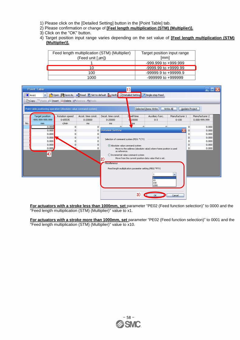
- 58 -
1) Please click on the [Detailed Setting] button in the [Point Table] tab. 2) Please confirmation or change of [Feel length multiplication (STM) (Multiplier)]. 3) Click on the "OK" button. 4) Target position input range varies depending on the set value of [Feel length multiplication (STM)
(Multiplier)].
Feed length multiplication (STM) (Multiplier)
(Feed unit [μm])
Target position input range [mm]
1 -999.999 to +999.999
10 -9999.99 to +9999.99
100 -99999.9 to +99999.9
1000 -999999 to +999999
For actuators with a stroke less than 1000mm, set parameter “PE02 (Feed function selection)” to 0000 and the "Feed length multiplication (STM) (Multiplier)" value to x1. For actuators with a stroke more than 1000mm, set parameter “PE02 (Feed function selection)” to 0001 and the "Feed length multiplication (STM) (Multiplier)" value to x10.
1)
2)
4)
3)
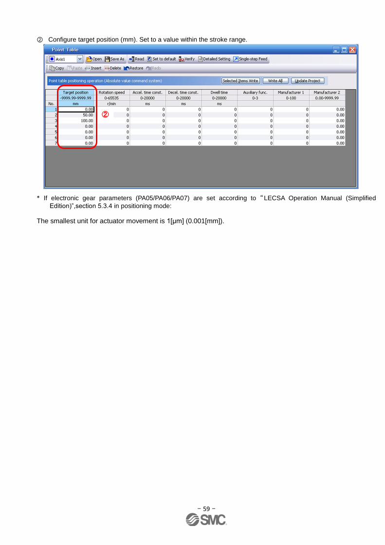
- 59 -
② Configure target position (mm). Set to a value within the stroke range.
* If electronic gear parameters (PA05/PA06/PA07) are set according to“LECSA Operation Manual (Simplified
Edition)”,section 5.3.4 in positioning mode:
The smallest unit for actuator movement is 1[μm] (0.001[mm]).
②

- 60 -
5.7.4 Point table (Rotation Speed) Configuration <Rotation Speed Configuration>
① Rotation speed configuration: *r/min (rpm): motor command rotation speed (motor rotations/min) Travel speed (mm/s) must be converted into rotation speed (r/min). See below for the conversion formula.
Example using a 20[mm] Lead Actuator with target travel speed of 500[mm/sec]
The rotation speed must be a value between 0 and the allowable actuator speed. The actuator will not operate if set to 0.
Too low rotation speed (r/min), may cause vibration (resonance);
Rotation Speed (rpm) = {Speed (mm/s) ÷ Lead (mm) }×60 (S) = {500 (mm/s) ÷20 (mm) }×60 (s) =1500 (rpm)
Travel distance per second
Travel distance per rotation
Rotations per second
÷
①
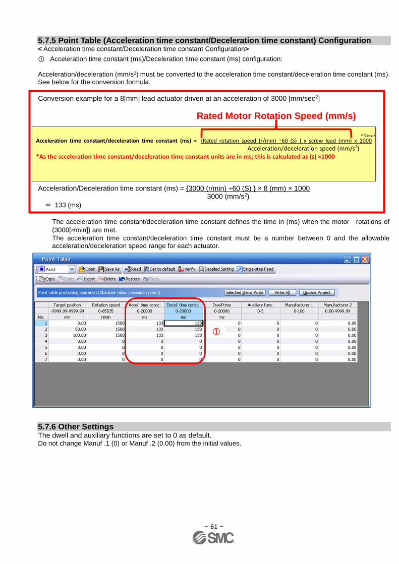
- 61 -
5.7.5 Point Table (Acceleration time constant/Deceleration time constant) Configuration < Acceleration time constant/Deceleration time constant Configuration>
① Acceleration time constant (ms)/Deceleration time constant (ms) configuration: Acceleration/deceleration (mm/s2) must be converted to the acceleration time constant/deceleration time constant (ms). See below for the conversion formula.
Conversion example for a 8[mm] lead actuator driven at an acceleration of 3000 [mm/sec2] Acceleration/Deceleration time constant (ms) = {3000 (r/min) ÷60 (S) } × 8 (mm) × 1000 3000 (mm/s2)
= 133 (ms)
The acceleration time constant/deceleration time constant defines the time in (ms) when the motor rotations of
(3000[r/min]) are met.
The acceleration time constant/deceleration time constant must be a number between 0 and the allowable acceleration/deceleration speed range for each actuator.
5.7.6 Other Settings The dwell and auxiliary functions are set to 0 as default. Do not change Manuf .1 (0) or Manuf .2 (0.00) from the initial values.
Acceleration time constant/deceleration time constant (ms) = {Rated rotation speed (r/min) ÷60 (S) } x screw lead (mm) x 1000
Acceleration/deceleration speed (mm/s2) *As the scceleration time constant/deceleration time constant units are in ms; this is calculated as (s) ×1000
Rated Motor Rotation Speed (mm/s)
①
*Note)
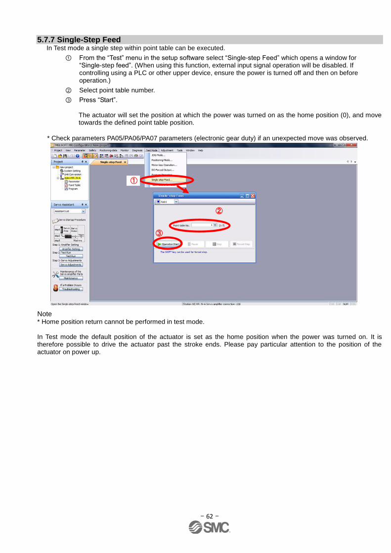
- 62 -
5.7.7 Single-Step Feed In Test mode a single step within point table can be executed.
① From the “Test” menu in the setup software select “Single-step Feed” which opens a window for “Single-step feed”. (When using this function, external input signal operation will be disabled. If controlling using a PLC or other upper device, ensure the power is turned off and then on before operation.)
② Select point table number.
③ Press “Start”. The actuator will set the position at which the power was turned on as the home position (0), and move towards the defined point table position.
* Check parameters PA05/PA06/PA07 parameters (electronic gear duty) if an unexpected move was observed.
Note * Home position return cannot be performed in test mode. In Test mode the default position of the actuator is set as the home position when the power was turned on. It is therefore possible to drive the actuator past the stroke ends. Please pay particular attention to the position of the actuator on power up.
①
②
③
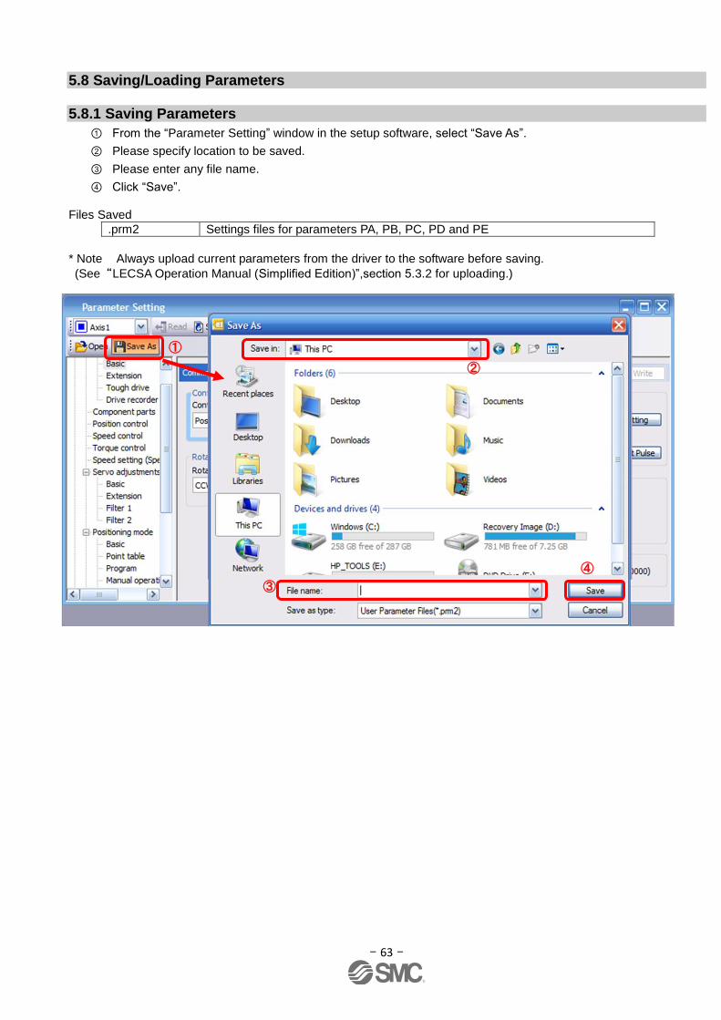
- 63 -
5.8 Saving/Loading Parameters
5.8.1 Saving Parameters
① From the “Parameter Setting” window in the setup software, select “Save As”.
② Please specify location to be saved.
③ Please enter any file name.
④ Click “Save”. Files Saved
.prm2 Settings files for parameters PA, PB, PC, PD and PE
* Note Always upload current parameters from the driver to the software before saving.
(See“LECSA Operation Manual (Simplified Edition)”,section 5.3.2 for uploading.)
①
②
③
④
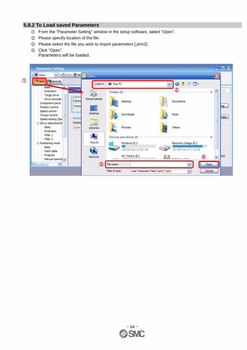
- 64 -
5.8.2 To Load saved Parameters
① From the “Parameter Setting” window in the setup software, select “Open”.
② Please specify location of the file.
③ Please select the file you wish to import parameters [.prm2].
④ Click “Open”.
Parameters will be loaded.
①
③
④
②

- 65 -
5.9 Saving/Loading Project
5.9.1 Saving Project
① From the “Project” menu in the setup software, select “Save As”.
② Please specify location to be saved.
③ Please enter any file name.
④ Click “Save”.
Project will be saved in the specified folder. If you change the drive / path name, it will be saved in the "drive ¥path name ¥ project name" folder you have changed.
* Note Always upload current parameters from the driver to the software before saving.
(See“LECSA Operation Manual (Simplified Edition)”,section 5.3.2 for uploading.)
①
②
③
④
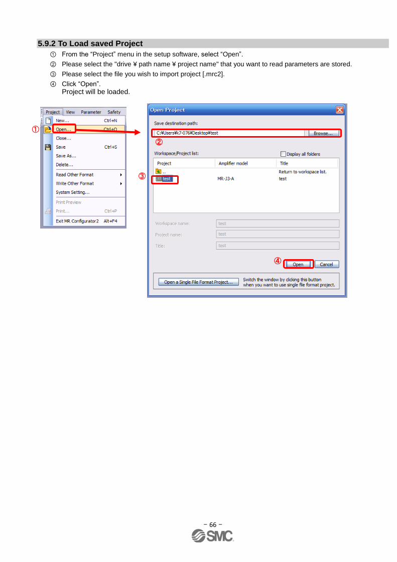
- 66 -
5.9.2 To Load saved Project
① From the “Project” menu in the setup software, select “Open”.
② Please select the "drive ¥ path name ¥ project name" that you want to read parameters are stored.
③ Please select the file you wish to import project [.mrc2].
④ Click “Open”.
Project will be loaded.
①
②
④
③
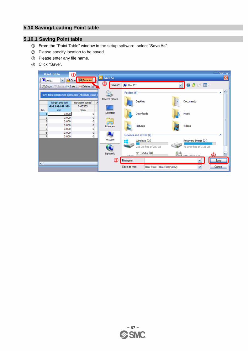
- 67 -
5.10 Saving/Loading Point table
5.10.1 Saving Point table
① From the “Point Table” window in the setup software, select “Save As”.
② Please specify location to be saved.
③ Please enter any file name.
④ Click “Save”.
①
③
④
②

- 68 -
5.10.2 To Load saved Point table
① From the “Point table” window in the setup software, select “Open”.
② Please specify location of the file.
③ Please select the file you wish to import point table [.ptb2].
④ Click “Open”.
Point table will be loaded.
①
③
④
②
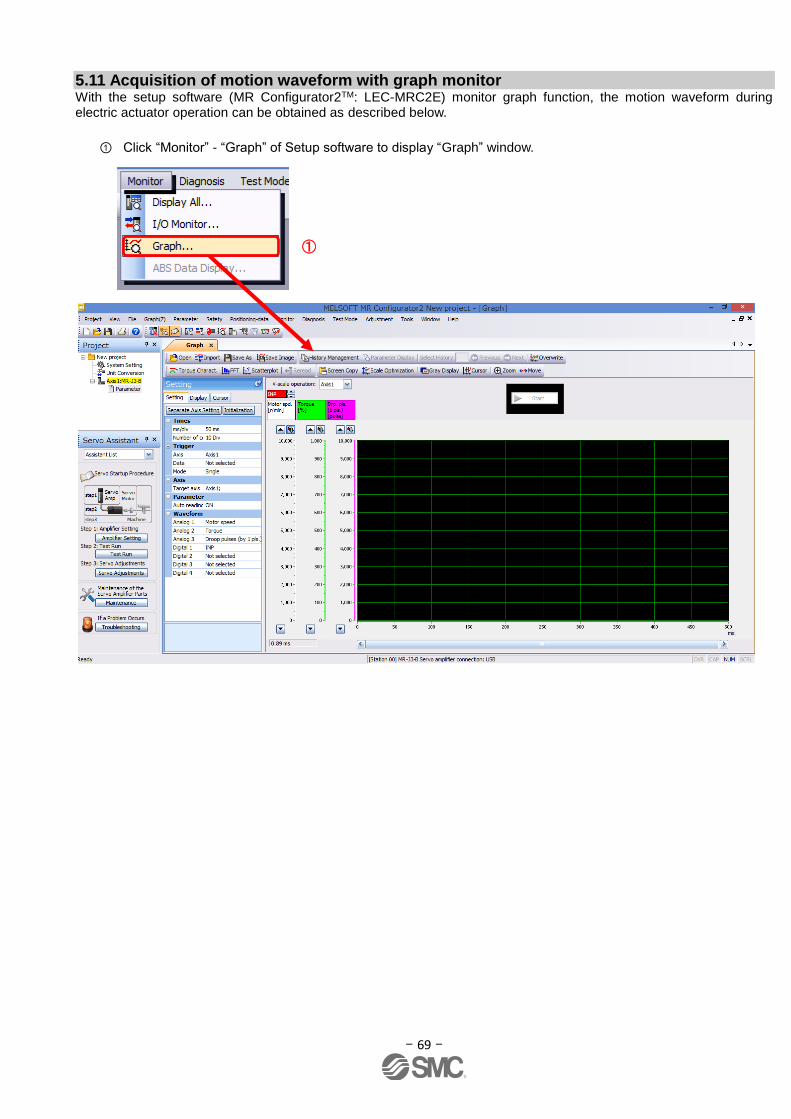
- 69 -
5.11 Acquisition of motion waveform with graph monitor With the setup software (MR Configurator2TM: LEC-MRC2E) monitor graph function, the motion waveform during electric actuator operation can be obtained as described below.
① Click “Monitor” - “Graph” of Setup software to display “Graph” window.
①
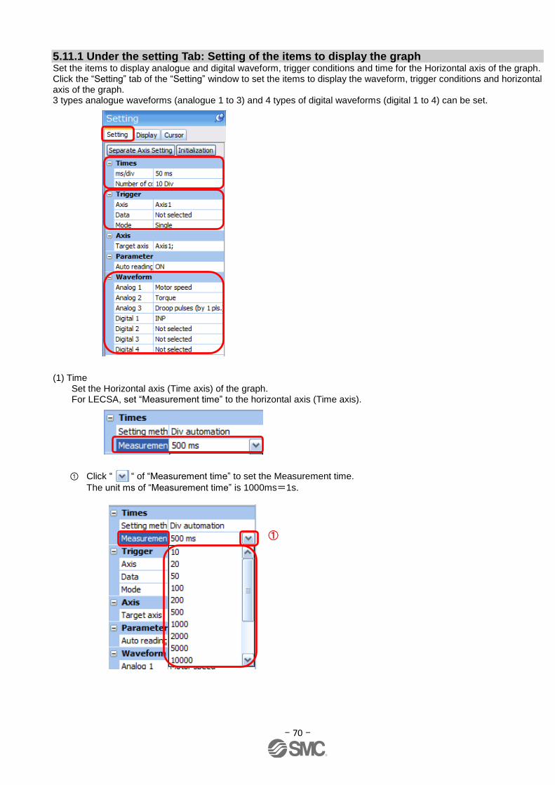
- 70 -
5.11.1 Under the setting Tab: Setting of the items to display the graph Set the items to display analogue and digital waveform, trigger conditions and time for the Horizontal axis of the graph. Click the “Setting” tab of the “Setting” window to set the items to display the waveform, trigger conditions and horizontal axis of the graph. 3 types analogue waveforms (analogue 1 to 3) and 4 types of digital waveforms (digital 1 to 4) can be set.
(1) Time
Set the Horizontal axis (Time axis) of the graph. For LECSA, set “Measurement time” to the horizontal axis (Time axis).
① Click “ “ of “Measurement time” to set the Measurement time.
The unit ms of “Measurement time” is 1000ms=1s.
①
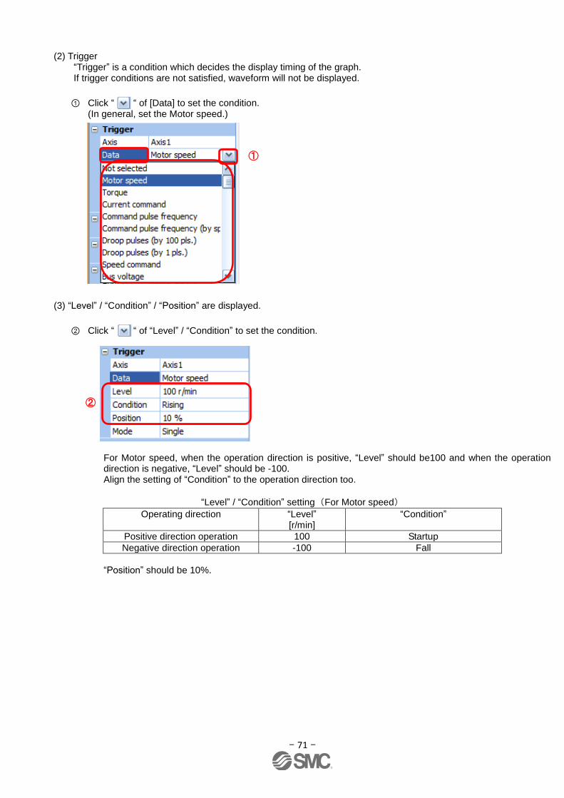
- 71 -
(2) Trigger
“Trigger” is a condition which decides the display timing of the graph. If trigger conditions are not satisfied, waveform will not be displayed.
① Click “ “ of [Data] to set the condition. (In general, set the Motor speed.)
(3) “Level” / “Condition” / “Position” are displayed.
② Click “ “ of “Level” / “Condition” to set the condition.
For Motor speed, when the operation direction is positive, “Level” should be100 and when the operation direction is negative, “Level” should be -100. Align the setting of “Condition” to the operation direction too.
“Level” / “Condition” setting(For Motor speed)
Operating direction “Level” [r/min]
“Condition”
Positive direction operation 100 Startup
Negative direction operation -100 Fall
“Position” should be 10%.
②
①
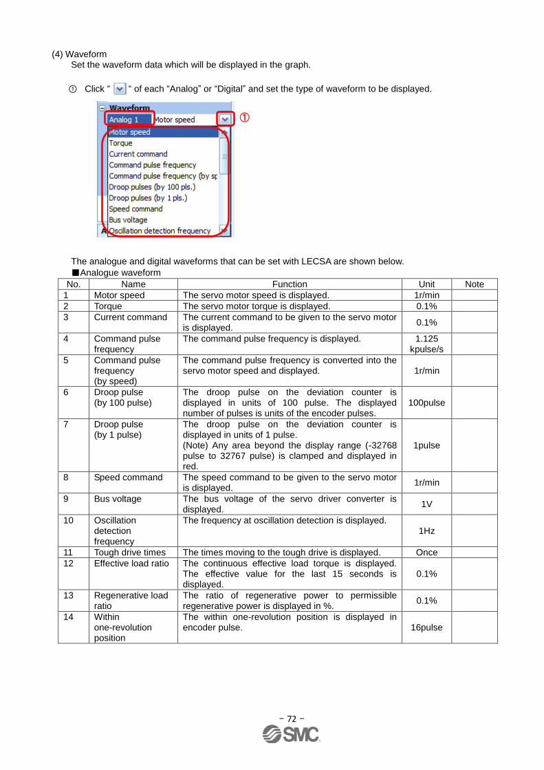
- 72 -
(4) Waveform
Set the waveform data which will be displayed in the graph.
① Click “ “ of each “Analog” or “Digital” and set the type of waveform to be displayed.
The analogue and digital waveforms that can be set with LECSA are shown below.
■Analogue waveform
No. Name Function Unit Note
1 Motor speed The servo motor speed is displayed. 1r/min
2 Torque The servo motor torque is displayed. 0.1%
3 Current command The current command to be given to the servo motor is displayed.
0.1%
4 Command pulse frequency
The command pulse frequency is displayed. 1.125 kpulse/s
5 Command pulse frequency (by speed)
The command pulse frequency is converted into the servo motor speed and displayed. 1r/min
6 Droop pulse (by 100 pulse)
The droop pulse on the deviation counter is displayed in units of 100 pulse. The displayed number of pulses is units of the encoder pulses.
100pulse
7 Droop pulse (by 1 pulse)
The droop pulse on the deviation counter is displayed in units of 1 pulse. (Note) Any area beyond the display range (-32768 pulse to 32767 pulse) is clamped and displayed in red.
1pulse
8 Speed command The speed command to be given to the servo motor is displayed.
1r/min
9
Bus voltage The bus voltage of the servo driver converter is displayed.
1V
10 Oscillation detection frequency
The frequency at oscillation detection is displayed. 1Hz
11 Tough drive times The times moving to the tough drive is displayed. Once
12 Effective load ratio The continuous effective load torque is displayed. The effective value for the last 15 seconds is displayed.
0.1%
13 Regenerative load ratio
The ratio of regenerative power to permissible regenerative power is displayed in %.
0.1%
14 Within one-revolution position
The within one-revolution position is displayed in encoder pulse. 16pulse
①
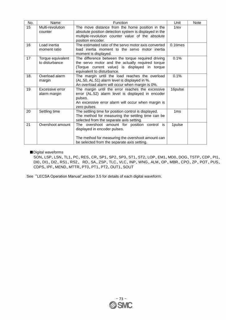
- 73 -
No. Name Function Unit Note
15 Multi-revolution counter
The move distance from the home position in the absolute position detection system is displayed in the multiple-revolution counter value of the absolute position encoder.
1rev
16 Load inertia moment ratio
The estimated ratio of the servo motor axis converted load inertia moment to the servo motor inertia moment is displayed.
0.1times
17 Torque equivalent to disturbance
The difference between the torque required driving the servo motor and the actually required torque (Torque current value) is displayed in torque equivalent to disturbance.
0.1%
18. Overload alarm margin
The margin until the load reaches the overload (AL.50, AL.51) alarm level is displayed in %. An overload alarm will occur when margin is 0%.
0.1%
19 Excessive error alarm margin
The margin until the error reaches the excessive error (AL.52) alarm level is displayed in encoder pulses. An excessive error alarm will occur when margin is zero pulses.
16pulse
20 Settling time The settling time for position control is displayed. The method for measuring the settling time can be selected from the separate axis setting.
1ms
21 Overshoot amount The overshoot amount for position control is displayed in encoder pulses. The method for measuring the overshoot amount can be selected from the separate axis setting.
1pulse
■Digital waveforms
SON、LSP、LSN、TL1、PC、RES、CR、SP1、SP2、SP3、ST1、ST2、LOP、EM1、MD0、DOG、TSTP、CDP、PI1、
DI0、DI1、DI2、RS1、RS2、 RD、SA、ZSP、TLC、VLC、INP、WNG、ALM、OP、MBR、CPO、ZP、POT、PUS、
CDPS、IPF、MEND、MTTR、PT0、PT1、PT2、OUT1、SOUT
See “LECSA Operation Manual”,section 3.5 for details of each digital waveform.
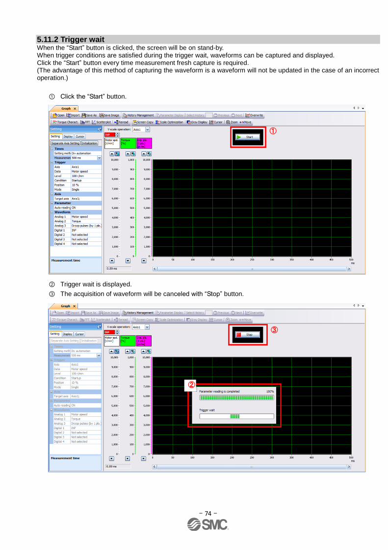
- 74 -
5.11.2 Trigger wait When the “Start” button is clicked, the screen will be on stand-by. When trigger conditions are satisfied during the trigger wait, waveforms can be captured and displayed. Click the “Start” button every time measurement fresh capture is required. (The advantage of this method of capturing the waveform is a waveform will not be updated in the case of an incorrect operation.)
① Click the “Start” button.
② Trigger wait is displayed.
③ The acquisition of waveform will be canceled with “Stop” button.
①
③
②
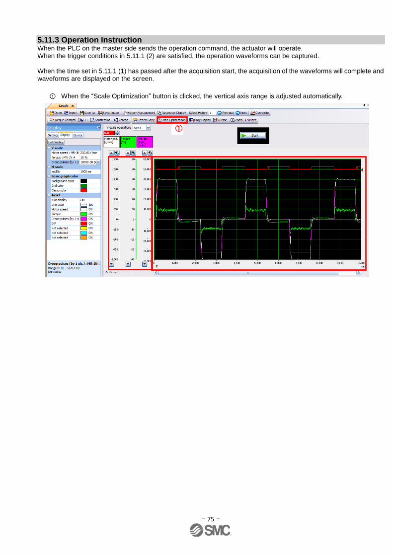
- 75 -
5.11.3 Operation Instruction When the PLC on the master side sends the operation command, the actuator will operate. When the trigger conditions in 5.11.1 (2) are satisfied, the operation waveforms can be captured. When the time set in 5.11.1 (1) has passed after the acquisition start, the acquisition of the waveforms will complete and waveforms are displayed on the screen.
① When the “Scale Optimization” button is clicked, the vertical axis range is adjusted automatically.
①

- 76 -
5.11.4 Saving of waveform After the waveform is displayed, it is possible to save the data in 3 ways.
① Click the “Save As” button. Select the folder in which the step data is to be saved and save the data. Waveform data file (extension: gpf2) will be prepared. If the waveform condition needs to be checked, it can be displayed on the graph window.
② Click the “Save Image” button. Select the folder in which the step data is to be saved and save the data. An Image file (extension: jpg) will be prepared.
③ Click the “Screen Copy” button. Save the displayed waveform screen (print screen).
① ②
③

- 77 -
5.12 Display All Monitor List The method how to obtain the electric actuator condition is described with the display all function of the setup software.
① Click “Monitor” - “Display All” of the setup software to display “Display All” window.
② The condition of each item is displayed. For off line of the setup software, [----] will be displayed.
The following items are displayed for LECSA.
No. Name Function Indication
range Unit
1 Cumulative feedback pulses
Feedback pulses from the servo motor encoder are counted and displayed. When exceed 999999999, it returns to zero. Press the [Clear] button to reset the display value to 0 (zero). Reverse rotation is indicated by a minus (-) sign.
-999999999 to 999999999
pulse
2 Servo motor speed The servo motor speed is displayed. The value rounded off is displayed in 0.1r/min. Reverse rotation is indicated by a minus (-) sign.
-5400 to
5400 r/min
3 Droop pulses The number of droop pulses in the deviation counter is displayed. Reverse rotation is indicated by a minus (-) sign.
-999999999 to 999999999
pulse
4 Cumulative command pulses
The position command input pulses are counted and displayed. Press the [Clear] button to reset the display value to zero. Reverse rotation is indicated by a minus (-) sign.
-999999999 to 999999999
pulse
①
②
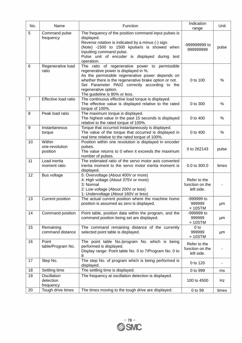
- 78 -
No. Name Function Indication
range Unit
5 Command pulse frequency
The frequency of the position command input pulses is displayed. Reverse rotation is indicated by a minus (-) sign. (Note) -1500 to 1500 kpulse/s is showed when inputting command pulse. Pulse unit of encoder is displayed during test operation.
-999999999 to 999999999
pulse
6 Regenerative load ratio
The ratio of regenerative power to permissible regenerative power is displayed in %. As the permissible regenerative power depends on whether there is the regenerative brake option or not. Set Parameter PA02 correctly according to the regenerative option. The guideline is 80% or less.
0 to 100 %
7 Effective load ratio The continuous effective load torque is displayed. The effective value is displayed relative to the rated torque of 100%.
0 to 300 %
8 Peak load ratio The maximum torque is displayed. The highest value in the past 15 seconds is displayed relative to the rated torque of 100%.
0 to 400 %
9 Instantaneous torque
Torque that occurred instantaneously is displayed. The value of the torque that occurred is displayed in real time relative to the rated torque of 100%.
0 to 400 %
10 Within one-revolution position
Position within one revolution is displayed in encoder pulses. The value returns to 0 when it exceeds the maximum number of pulses.
0 to 262143 pulse
11 Load inertia moment ratio
The estimated ratio of the servo motor axis converted inertia moment to the servo motor inertia moment is displayed.
0.0 to 300.0 times
12 Bus voltage 5: Overvoltage (About 400V or more) 4: High voltage (About 375V or more) 3: Normal 2: Low voltage (About 200V or less) 1: Undervoltage (About 160V or less)
Refer to the function on the
left side. -
13 Current position The actual current position where the machine home position is assumed as zero is displayed.
-999999 to 999999
× 10STM μm
14 Command position Point table, position data within the program, and the command position being set are displayed.
-999999 to 999999
× 10STM μm
15 Remaining command distance
The command remaining distance of the currently selected point table is displayed.
0 to 999999
× 10STM μm
16 Point table/Program No.
The point table No./program No. which is being performed is displayed. Display range: Point table No. 0 to 7/Program No. 0 to 8
Refer to the function on the
left side. -
17 Step No. The step No. of program which is being performed is displayed.
0 to 120 -
18 Settling time The settling time is displayed. 0 to 999 ms
19 Oscillation detection frequency
The frequency at oscillation detection is displayed. 100 to 4500 Hz
20 Tough drive times The times moving to the tough drive are displayed. 0 to 99 times

- 79 -
6. Home Position Return Method
6.1 Position Control Mode (Pulse Input)
When using the home position return in position control mode (pulse input), use the home position return function in
the positioning module of the upper PLC. Please see product operation manuals for positioning module layouts, parameter configuration, home position return method etc.
6.2 Positioning mode (point table)
In positioning mode (point table) a home position return function is available. There are 6 types of home position
return as shown below. See“LECSA Operation Manual”,section 13.6 for details.
Type Home position return method Features
Dog type
With Deceleration started at the detection of front edge of a proximity dog switch signal,
the position where the first Z-phase signal is given past the rear edgeof the dog signal
or a motion has been made over the home position shift distance starting from the
Z-phase signal is defined as a home position. (Note)
General home position return
method using a proximity dog.
Good repeat accuracy of home
position return
Decreases product load.
Used when the width of the
proximity dog can be set greater
than the deceleration distance
of the servo motor.
Count type
With Deceleration started at the detection of front edge of a proximity dog switch signal,
the position where the first Z-phase signal is given after advancement over the preset
moving distance after the proximity dog switch signal or a motion has been made over
the home position shift distance starting from the Z-phase signal is defined as a home
position.
Home position return method
using a proximity dog.
Used when it is minimisation of
the proximity dog length is
required.
Data set type An arbitrary position defined as a home position. No proximity dog required.
Stopper type
The position where the actuator stops when its slider is pressed against a machine stop
is defined as a home position.
Since the machine part collides
with the machine be fully
lowered.
The machine and stopper
strength must be increased.
Home position
ignorance (Servo-on
position as home
position)
The position where servo is switched on is defined as a home position.
Dog type rear end
reference
The position where the axis, which had started dcceleration of the front edge of a
proximity dog switch signal, has moved the after-proximity dog moving distance and
home position shift distance after it has passed the rear edge of proximity dog switch
signal is defined as a home position.
Z-phase signal not required.
Count type front end
reference
The position where the axis, which had started dcceleration at the front edge of a
proximity dog switch signal, has moved the after-proximity dog moving distance and
home position shift distance is defined as a home position.
Z-phase signal not required.
Dog cradle type The position where the first Z-phase signal is detected after detection of the proximity
dog front edge signal is defined as a home position.
Note. The Z-phase signal is a signal recognised in the driver once per servo motor revolution. This cannot be used as an output signal.
Set parameter PE03 (Home position return type) for home position return. The parameter recommended in “LECSA
Operation Manual (Simplified Edition)”,section 5.3.4 is the stopper type (PE03:0003). Please select the home position
return as appropriate to the customer application.
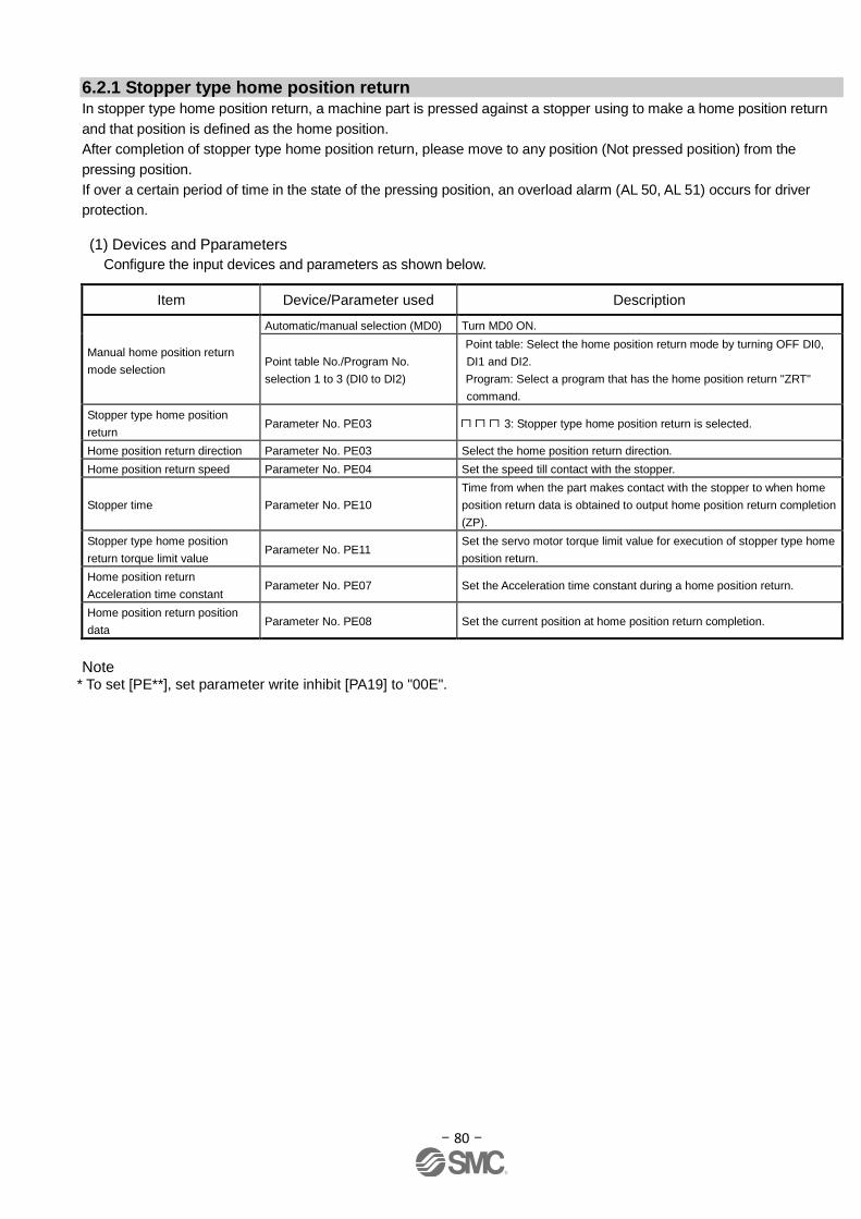
- 80 -
6.2.1 Stopper type home position return In stopper type home position return, a machine part is pressed against a stopper using to make a home position return
and that position is defined as the home position.
After completion of stopper type home position return, please move to any position (Not pressed position) from the
pressing position.
If over a certain period of time in the state of the pressing position, an overload alarm (AL 50, AL 51) occurs for driver
protection.
(1) Devices and Pparameters
Configure the input devices and parameters as shown below.
Item Device/Parameter used Description
Manual home position return
mode selection
Automatic/manual selection (MD0) Turn MD0 ON.
Point table No./Program No.
selection 1 to 3 (DI0 to DI2)
Point table metho Point table: Select the home position return mode by turning OFF DI0,
DI1 and DI2.
Program metho Program: Select a program that has the home position return "ZRT"
command.
Stopper type home position
return Parameter No. PE03 3: Stopper type home position return is selected.
Home position return direction Parameter No. PE03 Select the home position return direction.
Home position return speed Parameter No. PE04 Set the speed till contact with the stopper.
Stopper time Parameter No. PE10
Time from when the part makes contact with the stopper to when home
position return data is obtained to output home position return completion
(ZP).
Stopper type home position
return torque limit value Parameter No. PE11
Set the servo motor torque limit value for execution of stopper type home
position return.
Home position return
Acceleration time constant Parameter No. PE07 Set the Acceleration time constant during a home position return.
Home position return position
data Parameter No. PE08 Set the current position at home position return completion.
Note
* To set [PE**], set parameter write inhibit [PA19] to "00E".
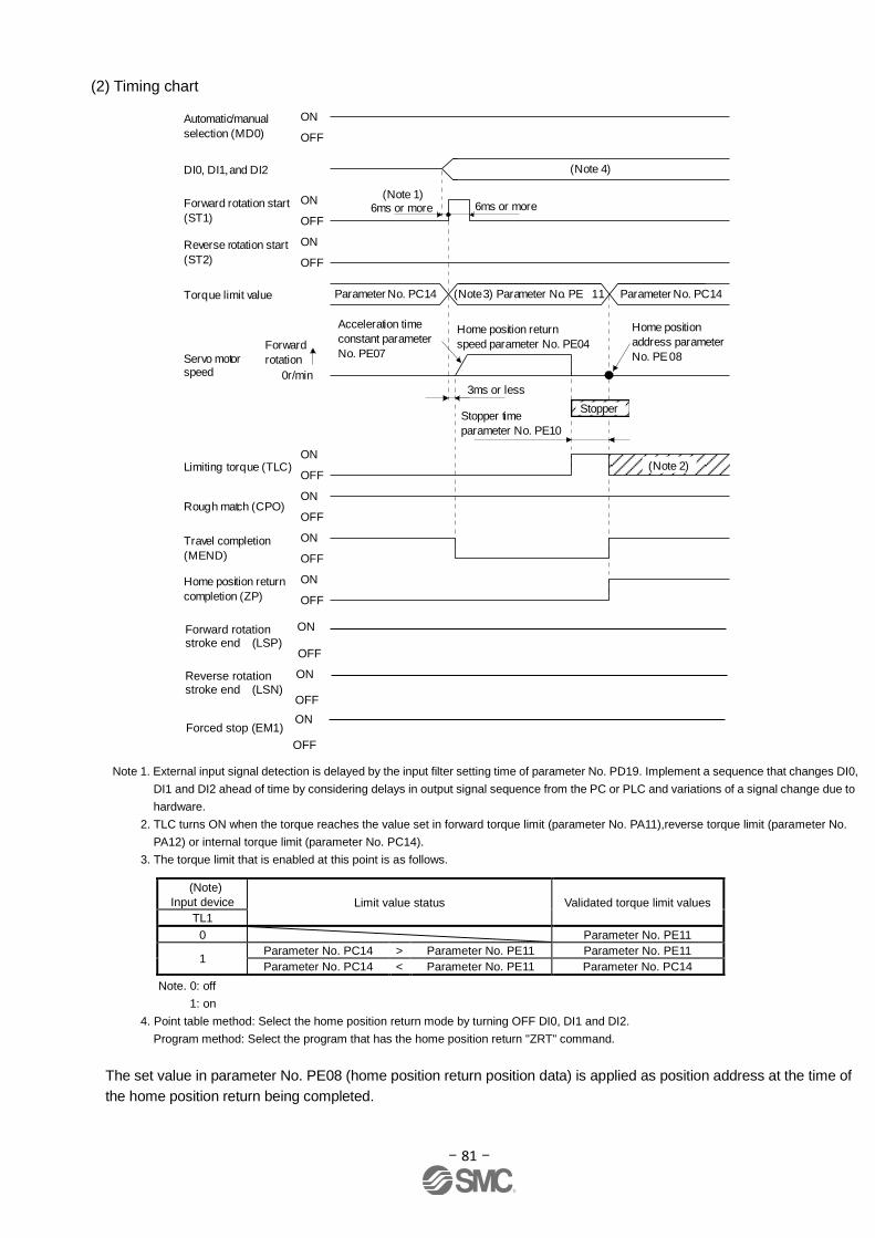
- 81 -
(2) Timing chart
Forward
rotation
0r/min
ON
OFF
Automatic/manual
selection (MD0)
ON
OFF
Travel completion
(MEND)
ON
OFFRough match (CPO)
Servo motor speed
Acceleration time
constant parameter
No. PE07
Home position return
speed parameter No. PE04
Home position
address parameter
No. PE08
3ms or less
ON
OFF
6ms or moreForward rotation start
(ST1)
ON
OFF
Reverse rotation start
(ST2)
Stopper time
parameter No. PE10
ON
OFFLimiting torque (TLC)
Parameter No. PC14 (Note 3) Parameter No. PE 11 Parameter No. PC14Torque limit value
(Note 4)DI0, DI1, and DI2
ON
OFF
Home position return
completion (ZP)
Stopper
(Note 1)6ms or more
(Note 2)
Note 1. External input signal detection is delayed by the input filter setting time of parameter No. PD19. Implement a sequence that changes DI0,
DI1 and DI2 ahead of time by considering delays in output signal sequence from the PC or PLC and variations of a signal change due to
hardware.
2. TLC turns ON when the torque reaches the value set in forward torque limit (parameter No. PA11),reverse torque limit (parameter No.
PA12) or internal torque limit (parameter No. PC14).
3. The torque limit that is enabled at this point is as follows.
(Note)
Input device Limit value status Validated torque limit values
TL1
0 Parameter No. PE11
1 Parameter No. PC14 > Parameter No. PE11 Parameter No. PE11
Parameter No. PC14 < Parameter No. PE11 Parameter No. PC14
Note. 0: off
1: on
4. Point table method: Select the home position return mode by turning OFF DI0, DI1 and DI2.
Program method: Select the program that has the home position return "ZRT" command.
The set value in parameter No. PE08 (home position return position data) is applied as position address at the time of
the home position return being completed.
ON
OFF
ON
OFF
ON
Forward rotation stroke end (LSP)
Reverse rotation stroke end (LSN)
Forced stop (EM1)
OFF
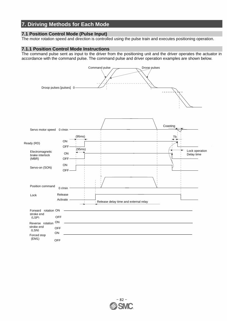
- 82 -
7. Diriving Methods for Each Mode
7.1 Position Control Mode (Pulse Input) The motor rotation speed and direction is controlled using the pulse train and executes positioning operation.
7.1.1 Position Control Mode Instructions The command pulse sent as input to the driver from the positioning unit and the driver operates the actuator in accordance with the command pulse. The command pulse and driver operation examples are shown below.
After-changing gain
Before-changing gainChange of each gain
CDT = 100ms
63.4%
Droop pulses [pulses] 0
Command pulse Droop pulses
CDL
CDL
(95ms)
(95ms)Electromagneticbrake interlock(MBR)
(Note 1) ON
ON
OFF
0 r/min
Base circuit
Servo motor speed
Servo-on (SON)ON
OFF
Coasting
Tb
Electromagneticbrake operationdelay time
Release
Position command(Note 4)
Electromagneticbrake
Release delay time and external relay (Note 2)
(Note 3)
0 r/min
Electromagnetic brake sequence output (parameter No. PC09)
Activate
OFF
ON
OFF
ON
OFF
ON
OFF
Forward rotation stroke end (LSP)
Reverse rotation stroke end (LSN)
Forced stop (EM1)
Ready (RD)
Lock
Lock operation Delay time

- 83 -
7.2 Speed control mode This mode allows for accurate, smooth control of the rotation speed and direction of the servo motor. * To set [PC**], set parameter write restriction [PA19] to "00E".
7.2.1 Speed Control Mode Operation Instruction The servo motor will rotate when signal ST1 and ST2 turn on. An operation example of the speed control mode is shown below.
Internal speed command settings
Speed command and speed
The servo motor operates at the speed set in parameters.
Up to 8 speeds can be set to the internal speed command.
The following table indicates the rotation direction according to forward rotation start (ST1) and reverse rotation
start (ST2) combination.
(Note 1) Input device (Note 2) Rotation direction
Forward rotation (CCW)
Reverse rotation (CW)
ST2 ST1
0 0 Stop (Servo lock)
0 1 Forward rotation (CCW)
1 0 Reverse rotation (CW)
1 1 Stop (Servo lock)
Note 1. 0: off
1: on
2. If the torque limit is canceled during servo lock, the servo
motor may suddenly rotate according to position deviation in
respect to the command position.
Connect the wirings as follows when operating in forward or reverse rotation with the internal speed command set
to the eighth speed.
Note that the inputs are configured as Current sink NPN Type
ST2
SP1
SP2
SP3
DOCOM
DICOM
24VDC
Servo amplifier
ST1
(Note 2)(Note 1)
Refer to “LECSA Operation Manual (Simplified Edition)”, section 5.5 for signal assignment.
(Note) Input device Speed command value
SP3 SP2 SP1
0 0 0 Internal speed command 0 (parameter No. PC05) Initial phase 0 0 1 Internal speed command 1 (parameter No. PC06)
0 1 0 Internal speed command 2 (parameter No. PC07)
0 1 1 Internal speed command 3 (parameter No. PC08)
1 0 0 Internal speed command 4 (parameter No. PC31)
1 0 1 Internal speed command 5 (parameter No. PC32)
1 1 0 Internal speed command 6 (parameter No. PC33)
1 1 1 Internal speed command 7 (parameter No. PC34)
Note. 0:OFF
1:ON
8 patterns of speed configurations are available for LECSA.
LECSA Speed Command Parameter Setting
Driver
Assignment of signals in the initial setting - LECSA: SP1 Assign signals "speed selection 2 (SP2) and speed selection 3 (SP3) "when the driver is used to [Internal speed command 7].
Forward rotation start Peverse rotation start
Speed selection 1 Speed selection 2 Speed selection 3
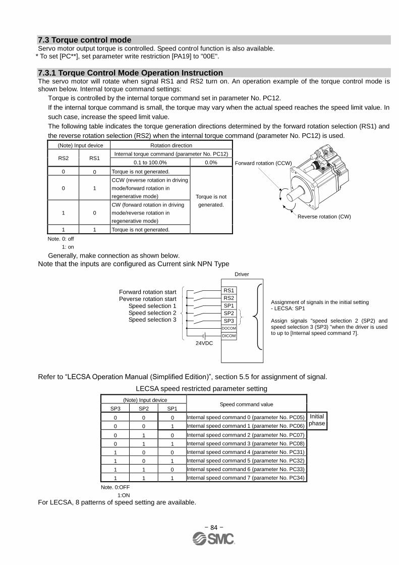
- 84 -
7.3 Torque control mode Servo motor output torque is controlled. Speed control function is also available.
* To set [PC**], set parameter write restriction [PA19] to "00E".
7.3.1 Torque Control Mode Operation Instruction The servo motor will rotate when signal RS1 and RS2 turn on. An operation example of the torque control mode is shown below. Internal torque command settings:
Torque is controlled by the internal torque command set in parameter No. PC12.
If the internal torque command is small, the torque may vary when the actual speed reaches the speed limit value. In
such case, increase the speed limit value.
The following table indicates the torque generation directions determined by the forward rotation selection (RS1) and
the reverse rotation selection (RS2) when the internal torque command (parameter No. PC12) is used.
(Note) Input device Rotation direction
Forward rotation (CCW)
Reverse rotation (CW)
RS2 RS1 Internal torque command (parameter No. PC12)
0.1 to 100.0% 0.0%
0 0 Torque is not generated.
Torque is not
generated.
0 1
CCW (reverse rotation in driving
mode/forward rotation in
regenerative mode)
1 0
CW (forward rotation in driving
mode/reverse rotation in
regenerative mode)
1 1 Torque is not generated.
Note. 0: off
1: on
Generally, make connection as shown below.
Note that the inputs are configured as Current sink NPN Type
SP2
SP3
DOCOM
DICOM
Servo amplifier
SP1
24VDC
(Note 2)
RS2
RS1
(Note 1)
Refer to “LECSA Operation Manual (Simplified Edition)”, section 5.5 for assignment of signal.
(Note) Input device Speed command value
SP3 SP2 SP1
0 0 0 Internal speed command 0 (parameter No. PC05) Initial phase
0 0 1 Internal speed command 1 (parameter No. PC06)
0 1 0 Internal speed command 2 (parameter No. PC07)
0 1 1 Internal speed command 3 (parameter No. PC08)
1 0 0 Internal speed command 4 (parameter No. PC31)
1 0 1 Internal speed command 5 (parameter No. PC32)
1 1 0 Internal speed command 6 (parameter No. PC33)
1 1 1 Internal speed command 7 (parameter No. PC34)
Note. 0:OFF
1:ON
For LECSA, 8 patterns of speed setting are available.
LECSA speed restricted parameter setting
Assignment of signals in the initial setting - LECSA: SP1 Assign signals "speed selection 2 (SP2) and speed selection 3 (SP3) "when the driver is used to up to [Internal speed command 7].
Driver
Forward rotation start Peverse rotation start
Speed selection 1 Speed selection 2 Speed selection 3
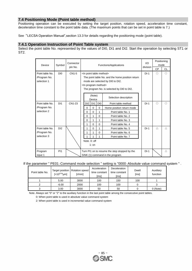
- 85 -
7.4 Positioning Mode (Point table method) Positioning operation can be executed by setting the target position, rotation speed, acceleration time constant, deceleration time constant to the point table data. (The maximum points that can be set in point table is 7.)
See “LECSA Operation Manual”,section 13.3 for details regarding the positioning mode (point table).
7.4.1 Operation Instruction of Point Table system Select the point table No. represented by the values of DI0, DI1 and DI2. Start the operation by selecting ST1 or ST2.
Device Symbol Connector
pin No. Functions/Applications
I/O
division
Positioning
mode
CP CL
Point table No.
/Program No.
selection 1
DI0 CN1-5 <In point table method>
The point table No. and the home position return
mode are selected by DI0 to DI2.
<In program method>
The program No. is selected by DI0 to DI2.
DI-1
(Note)
Device Selection description
Point table No.
/Program No.
selection 2
DI1 CN1-23 DI2 DI1 DI0 Point table method DI-1
0 0 0 Home position return mode
0 0 1 Point table No. 1
0 1 0 Point table No. 2
0 1 1 Point table No. 3
1 0 0 Point table No. 4
Point table No.
/Program No.
selection 3
DI2 1 0 1 Point table No. 5 DI-1
1 1 0 Point table No. 6
1 1 1 Point table No. 7
Note. 0: off
1: on
Program
input 1
PI1 Turn PI1 on to resume the step stopped by the
SINK (1) command in the program.
DI-1
If the parameter " PE01:Command mode selection " setting is "0000:Absolute value command system " .
Point table No. Target position
[×10STMμm]
Rotation speed
[r/min]
Acceleration
time constant
[ms]
Deceleration
time constant
[ms]
Dwell
[ms]
Auxiliary
function
1 5.00 3000 100 150 100 1
2 -6.00 2000 100 100 0 3
3 3.00 3000 50 50 0 0 (Note)
Note. Always set "0" or "2" to the auxiliary function in the last point table among the consecutive point tables.
0: When point table is used in absolute value command system
2: When point table is used in incremental value command system
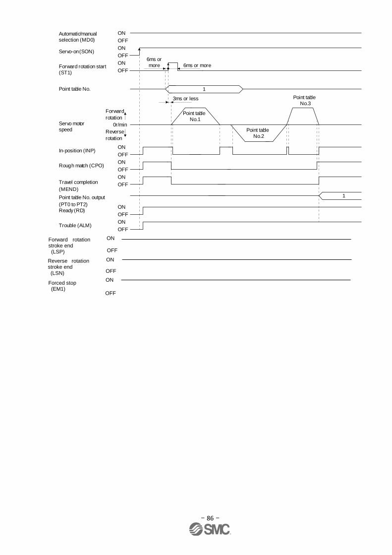
- 86 -
Point table No.1
ON
OFF
ON
OFF
ON
OFF
ON
OFF
ON
OFF
ON
OFF
6ms or more
Servo-on (SON)
Ready (RD)
Trouble (ALM)
Automatic/manual selection (MD0)
In-position (INP)
Rough match (CPO)
Point table No.
Servo motor speed
Forward
rotation
Reverse
rotation
0r/min
ON
OFFForward rotation start (ST1)
1
ON
OFF
(Note 2)Travel completion
(MEND)
Point table No. output
(PT0 to PT2)
3ms or less
Point table No.2
Point table No.3
1
(Note 1)6ms or more
ON
OFF
ON
OFF
ON
OFF
Forward rotation stroke end (LSP)
Reverse rotation stroke end (LSN)
Forced stop (EM1)
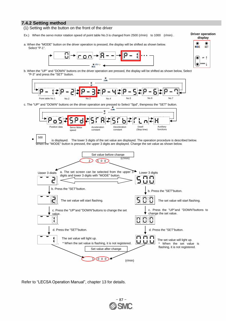
- 87 -
7.4.2 Setting method (1) Setting with the button on the front of the driver Refer to “LECSA Operation Manual”, chapter 13 for details.
Ex.) When the servo motor rotation speed of point table No.3 is changed from 2500 (r/min) to 1000 (r/min) .
a. When the "MODE" button on the driver operation is pressed, the display will be shifted as shown below. Select "P-1".
・・・
b. When the "UP" and "DOWN" buttons on the driver operation are pressed, the display will be shifted as shown below, Select "P-3" and press the "SET" button.
c. The "UP" and "DOWN" buttons on the driver operation are pressed to Select "Spd", thenpress the "SET" button.
Point table No.1 No.2 No.3 No.4 No.5 No.6 No.7
Position data Servo Motor speed
Acceleration constant
Deceleration constant
Dwell
(Stop time)
Auxiliary
functions
Driver operation display
UUPP
DDOOWWNN
* When the set value is flashing, it is not registered.
* When the set value is flashing, it is not registered.
a. The set screen can be selected from the upper 3 digits and lower 3 digits with "MODE" button.
Lower 3 digits
The set value will start flashing.
b. Press the "SET"button.
c. Press the "UP"and "DOWN"buttons to change the set value.
d. Press the "SET"button.
The set value will light up.
2 5 0 0
Set value before change
1 0 0 0
Set value after change
Upper 3 digits
b. Press the "SET"button.
c. Press the "UP"and "DOWN"buttons to change the set value.
d. Press the "SET"button.
The set value will start flashing.
The set value will light up.
(r/min)
(r/min)
• is displayed. The lower 3 digits of the set value are displayed. The operation procedure is described below. When the "MODE" button is pressed, the upper 3 digits are displayed. Change the set value as shown below.
500

- 88 -
7.5 Positioning Mode (Programimg Method) To perform the positioning operation, create a program using target position, rotation speed, acceleration constant and deceleration constant (The maximum number of programs is 8 for which a total of 120 steps can be created per program). Install the setup software, MR Configurator2TM : LEC-MRC2E which is required for setting the program data with the program system. *1 Setup software version 1.52E or above is required. *2. Setup software should be prepared by the user. *3. USB cable (LEC-MR-J3USB) is required for software installation.
See “LECSA Operation Manual”, section 13.4 for details regarding the positioning mode (programming method).
See “LECSA Operation Manual”, section 13.9 for details regarding programming methods.
7.5.1 Setting method
① Launch the setup software and select [Program] of [Positioning data].
② Select [Edit] on the program window to open the program edition window.
③ Create programs.
④ Click [OK].
⑤ Program data is written to the driver with [Writel] on the program window.
①
② ③
④
⑤

- 89 -
7.5.2 Command in the program system An example of the program commands is shown below.
See “LECSA Operation Manual”,section 13.4.2 for details regarding programming command.
The maximum number of program steps is 120. Though up to 8 programs can be created, the total number of each
program steps is up to 120.
The set program can be selected using point table no./program no. selection 1 (DI0) to point table no./program no.
selection 3 (DI2).
(1) Ex.) Command list
Command Name Setting Setting range Unit Indirect
addressing Description
SPN Speed (Motor
speed)
SPN
(Setting
value)
0 to
instantaneous
permissible
speed
r/min
Used to set the command speed of the servo motor for
positioning.
The set value should be equal to or less than the
instantaneous permissible speed of the servo motor.
STA Acceleration
time constant
STA
(Setting
value)
0 to 20000 ms
Used to set the Acceleration time constant.
The set value is the time in which the servo motor
reaches the rated speed from a stop.
It cannot be changed during command output.
STB Deceleration
time constant
STB
(Setting
value)
0 to 20000 ms
Used to set the Deceleration time constant.
The set value is the time in which the servo motor stops
from the rated speed.
It cannot be changed during command output.
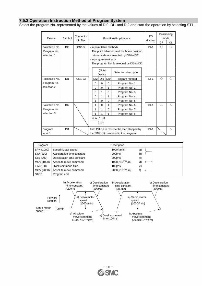
- 90 -
7.5.3 Operation Instruction Method of Program System Select the program No. represented by the values of DI0, DI1 and DI2 and start the operation by selecting ST1.
Device Symbol Connector
pin No. Functions/Applications
I/O
division
Positioning
mode
CP CL
Point table No.
/Program No.
selection 1
DI0 CN1-5 <In point table method>
The point table No. and the home position
return mode are selected by DI0 to DI2.
<In program method>
The program No. is selected by DI0 to DI2.
DI-1
(Note)
Device Selection description
Point table No.
/Program No.
selection 2
DI1 CN1-23 DI2 DI1 DI0 Program method DI-1
0 0 0 Program No. 1
0 0 1 Program No. 2
0 1 0 Program No. 3
0 1 1 Program No. 4
1 0 0 Program No. 5
Point table No.
/Program No.
selection 3
DI2 1 0 1 Program No. 6 DI-1
1 1 0 Program No. 7
1 1 1 Program No. 8
Note. 0: off
1: on
Program
input 1
PI1 Turn PI1 on to resume the step stopped by
the SINK (1) command in the program.
DI-1
Program Description
SPN (1000)
STA (200)
STB (300)
MOV (1000)
TIM (100)
MOV (2000)
STOP
Speed (Motor speed)
Acceleration time constant
Deceleration time constant
Absolute move command
Dwell command time
Absolute move command
Program end
1000[r/min]
200[ms]
300[ms]
1000[×10STMμm]
100[ms]
2000[×10STMμm]
a)
b)
c)
d)
e)
f)
0r/minServo motor speed
d) Absolute move command (1000 10STM m)
e) Dwell command time (100ms)
f) Absolute move command (2000 10STM m)
a) Servo motor speed (1000r/min)
b) Acceleration time constant (200ms)
b) Acceleration time constant (200ms)
c) Deceleration time constant (300ms)
c) Deceleration time constant (300ms)
a) Servo motor speed (1000r/min)
Forward rotation
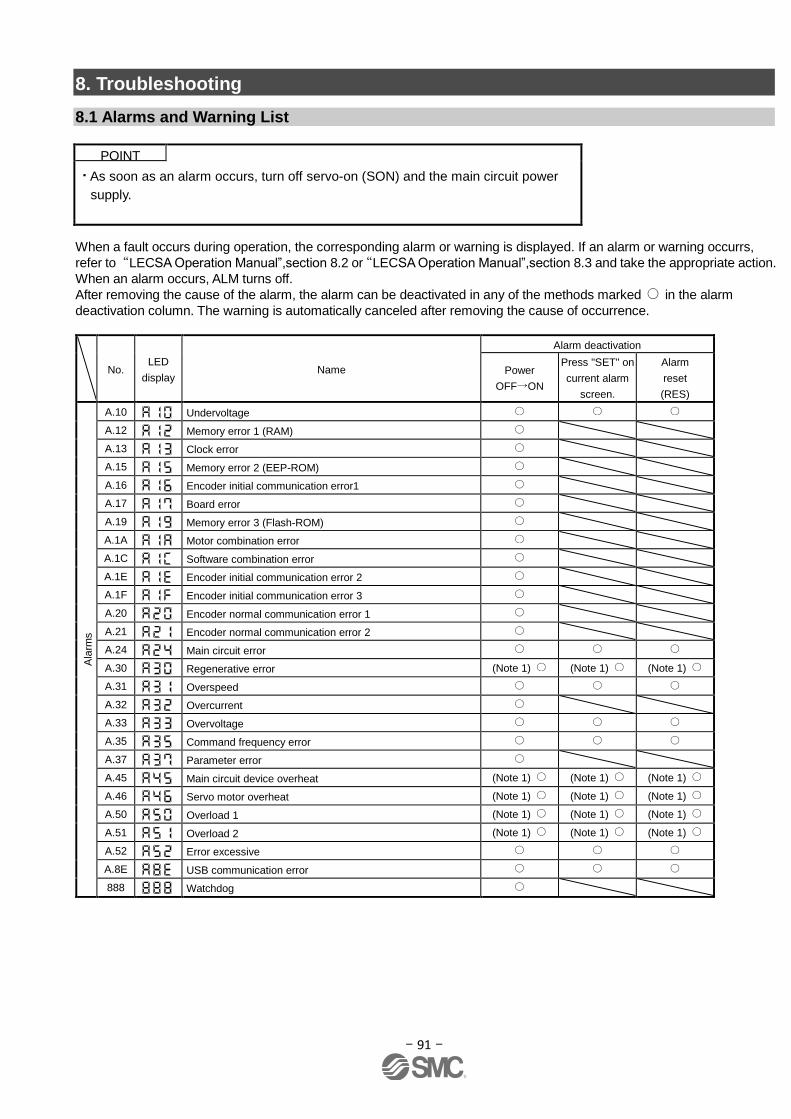
- 91 -
8. Troubleshooting
8.1 Alarms and Warning List
When a fault occurs during operation, the corresponding alarm or warning is displayed. If an alarm or warning occurrs,
refer to“LECSA Operation Manual”,section 8.2 or“LECSA Operation Manual”,section 8.3 and take the appropriate action.
When an alarm occurs, ALM turns off.
After removing the cause of the alarm, the alarm can be deactivated in any of the methods marked in the alarm
deactivation column. The warning is automatically canceled after removing the cause of occurrence.
No. LED
display Name
Alarm deactivation
Power
OFF ON
Press "SET" on
current alarm
screen.
Alarm
reset
(RES)
Ala
rms
A.10 Undervoltage
A.12 Memory error 1 (RAM)
A.13 Clock error
A.15 Memory error 2 (EEP-ROM)
A.16 Encoder initial communication error1
A.17 Board error
A.19 Memory error 3 (Flash-ROM)
A.1A Motor combination error
A.1C Software combination error
A.1E Encoder initial communication error 2
A.1F Encoder initial communication error 3
A.20 Encoder normal communication error 1
A.21 Encoder normal communication error 2
A.24 Main circuit error
A.30 Regenerative error (Note 1) (Note 1) (Note 1)
A.31 Overspeed
A.32 Overcurrent
A.33 Overvoltage
A.35 Command frequency error
A.37 Parameter error
A.45 Main circuit device overheat (Note 1) (Note 1) (Note 1)
A.46 Servo motor overheat (Note 1) (Note 1) (Note 1)
A.50 Overload 1 (Note 1) (Note 1) (Note 1)
A.51 Overload 2 (Note 1) (Note 1) (Note 1)
A.52 Error excessive
A.8E USB communication error
888 Watchdog
POINT
As soon as an alarm occurs, turn off servo-on (SON) and the main circuit power
supply.
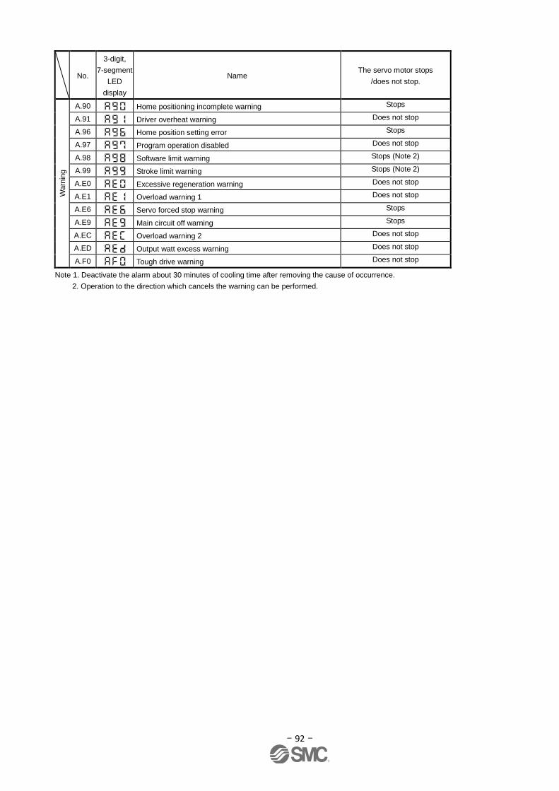
- 92 -
No.
3-digit,
7-segment
LED
display
Name The servo motor stops
/does not stop.
Warn
ing
A.90 Home positioning incomplete warning Stops
A.91 Driver overheat warning Does not stop
A.96 Home position setting error Stops
A.97 Program operation disabled Does not stop
A.98 Software limit warning Stops (Note 2)
A.99 Stroke limit warning Stops (Note 2)
A.E0 Excessive regeneration warning Does not stop
A.E1 Overload warning 1 Does not stop
A.E6 Servo forced stop warning Stops
A.E9 Main circuit off warning Stops
A.EC Overload warning 2 Does not stop
A.ED Output watt excess warning Does not stop
A.F0 Tough drive warning Does not stop
Note 1. Deactivate the alarm about 30 minutes of cooling time after removing the cause of occurrence.
2. Operation to the direction which cancels the warning can be performed.
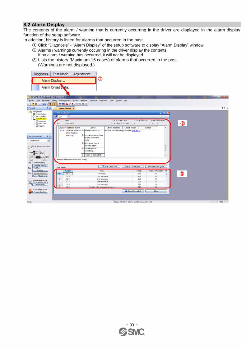
- 93 -
8.2 Alarm Display The contents of the alarm / warning that is currently occurring in the driver are displayed in the alarm display function of the setup software. In addition, history is listed for alarms that occurred in the past.
① Click “Diagnosis” - “Alarm Display” of the setup software to display “Alarm Display” window. ② Alarms / warnings currently occurring in the driver display the contents.
If no alarm / warning has occurred, it will not be displayed. ③ Lists the history (Maximum 16 cases) of alarms that occurred in the past.
(Warnings are not displayed.)
①
②
③

- 94 -
Revision history
No.LEC-OM05601
Dec./2012 1st printing
No.LEC-OM05602
Dec./2013 2nd printing
No.LEC-OM05603
Jun./2014 3rd printing
No.LEC-OM05604
Aug./2014 4th printing
No.LEC-OM05605
Oct./2014 5th printing
No.LEC-OM05606
Oct./2014 6th printing
No.LEC-OM05607
Dec./2014 7th printing
No.LEC-OM05608
Apr./2015 8th printing
No.LEC-OM05609
Sep./2015 9th printing
No.LEC-OM05610 (No.JXC※-OMT0051)
Sep./2016 10th printing
No.LEC-OM05611 (No.JXC※-OMT0051-A)
Jun./2017 11th printing
4-14-1, Sotokanda, Chiyoda-ku, Tokyo 101-0021 JAPAN Tel: + 81 3 5207 8249 Fax: +81 3 5298 5362
URL http://www.smcworld.com Note: Specifications are subject to change without prior notice and any obligation on the part of the manufacturer. © 2017 SMC Corporation All Rights Reserved