Embed Size (px)
Citation preview
1
KOBELCO WELDING TODAYProducts Spotlight
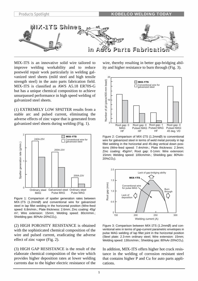
MIX-1TS is an innovative solid wire tailored toimprove welding workability and to reducepostweld repair work particularly in welding gal-vanized steel sheets (mild steel and high tensilestrength steel) in the auto parts fabrication field.MIX-1TS is classified as AWS A5.18 ER70S-Gbut has a unique chemical composition to achieveunsurpassed performance in high speed welding ofgalvanized steel sheets.
(1) EXTREMELY LOW SPATTER results from astable arc and pulsed current, eliminating theadverse effects of zinc vapor that is generated fromgalvanized steel sheets during welding (Fig. 1).
Figure 1: Comparison of spatter generation rates betweenMIX-1TS (1.2mmØ) and conventional wire for galvanizedsteel in lap fillet welding in the horizontal position (Wire-feedspeed: 6.8m/min.; Plate thickness: 2.6mm; Zinc coating: 45g/m2; Wire extension: 15mm; Welding speed: 80cm/min.;Shielding gas: 80%Ar-20%CO2).
(2) HIGH POROSITY RESISTANCE is obtainedwith the sophisticated chemical composition of thewire and pulsed current, eradicating the adverseeffect of zinc vapor (Fig. 2).
(3) HIGH GAP RESISTANCE is the result of theelaborate chemical composition of the wire whichprovides higher deposition rates at lower weldingcurrents due to the higher electric resistance of the
wire, thereby resulting in better gap-bridging abil-ity and higher resistance to burn through (Fig. 3).
Figure 2: Comparison of MIX-1TS (1.2mmØ) to conventionalwire for galvanized steel in terms of weld metal porosity in lapfillet welding in the horizontal and 45-deg vertical down posi-tions (Wire-feed speed: 7.4m/min.; Plate thickness: 2.3mm;Zinc coating: 45g/m2; Root gap: 0-1mm: Wire extension:15mm; Welding speed: 100cm/min.; Shielding gas: 80%Ar-20%CO2).
Figure 3: Comparison between MIX-1TS (1.2mmØ) and con-ventional wire in terms of gap-current parametric envelopes inpulse MAG welding of lap fillet joint in the horizontal position(Steel plate: 2.3-mm ordinary steel; Wire extension: 15mm;Welding speed: 130cm/min.; Shielding gas: 80%Ar-20%CO2).
In addition, MIX-1TS offers higher hot crack resis-tance in the welding of corrosion resistant steelthat contains higher P and Cu for auto parts appli-cations.
MIX-1TS Shines
in Auto Parts Fabricationin Auto Parts Fabrication
MIX-1TS Shines
2
KOBELCO WELDING TODAYPreface
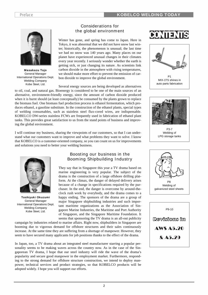
Considerations for the global environment
Winter has gone, and spring has come to Japan. Here inTokyo, it was abnormal that we did not have snow last win-ter; historically, the phenomenon is unusual; the last timewe had no snow was 140 years ago. Many places on ourplanet have experienced unusual changes in their climatesevery year recently. I seriously wonder whether the earth isgetting sick, or just changing its nature. As scientists linkcarbon dioxide in the atmosphere with rising temperatures,we should make more effort to prevent the emission of car-bon dioxide to improve the global environment.
Several energy sources are being developed as alternativesto oil, coal, and natural gas. Bioenergy is considered to be one of the main sources of analternative, environment-friendly energy, since the amount of carbon dioxide producedwhen it is burnt should (at least conceptually) be consumed by the plants grown to replacethe biomass fuel. One biomass fuel production process is ethanol fermentation, which pro-duces ethanol, a gasoline substitute. In the construction of the ethanol plants, special typesof welding consumables, such as stainless steel flux-cored wires, are indispensable.KOBELCO DW-series stainless FCWs are frequently used in fabrication of ethanol planttanks. This provides great satisfaction to us from the stand points of business and improv-ing the global environment.
I will continue my business, sharing the viewpoints of our customers, so that I can under-stand what our customers want to improve and what problems they want to solve. I knowthat KOBELCO is a customer-oriented company, so you can count on us for improvementsand solutions you need to better your welding business.
Masakazu TojoGeneral Manager
International Operations Dept.Welding CompanyKobe Steel, Ltd.
Boosting our business in theBooming Shipbuilding Industry
They say that in Singapore this year a TV drama based onmarine engineering is very popular. The subject of thedrama is the construction of a large offshore drilling plat-form. At the climax, the danger of delayed delivery arisesbecause of a change in specifications required by the pur-chaser. In the end, the danger is overcome by around-the-clock rush work by everybody, and the drama comes to ahappy ending. The sponsors of the drama are a group ofmajor Singapore shipbuilding industries and such impor-tant maritime organizations as the Association of Sin-gapore Marine Industries, the Maritime and Port Authorityof Singapore, and the Singapore Maritime Foundation. Itseems that sponsoring the TV drama is an all-out publicity
campaign by industries related to marine affairs. Right now, shipbuilders in Singapore arebooming due to vigorous demand for offshore structures and their sales continuouslyincrease. At the same time they are suffering from a shortage of manpower. However, theyseem to have secured many applicants for job positions thanks to the effect of the drama.
In Japan, too, a TV drama about an integrated steel manufacturer starring a popular per-sonality seems to be making waves across the country now. As in the case of the Sin-gaporean TV drama, I hope that our steel industry will ride the wave of the drama’spopularity and secure good manpower in the employment market. Furthermore, respond-ing to the strong demand for offshore structure construction, we intend to deploy man-power, technical services and product strategies, so that KOBELCO products will beadopted widely. I hope you will support our efforts.
Toshiyuki OkuzumiGeneral Manager
International Operations Dept.Welding CompanyKobe Steel, Ltd.
P1MIX-1TS shines in
auto parts fabrication
P3-7Welding of
LPG storage tanks
P8Welding of
galvanized steel sheets
P9-10
3
KOBELCO WELDING TODAYTechnical Highlight
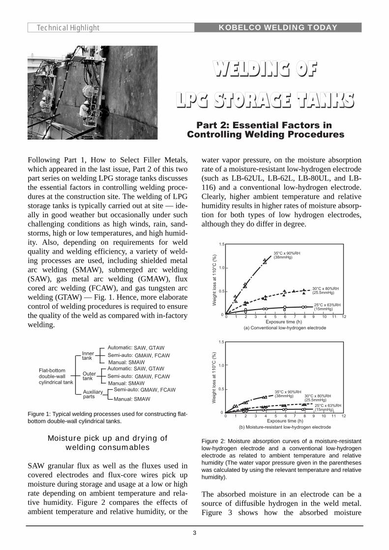
Following Part 1, How to Select Filler Metals,which appeared in the last issue, Part 2 of this twopart series on welding LPG storage tanks discussesthe essential factors in controlling welding proce-dures at the construction site. The welding of LPGstorage tanks is typically carried out at site — ide-ally in good weather but occasionally under suchchallenging conditions as high winds, rain, sand-storms, high or low temperatures, and high humid-ity. Also, depending on requirements for weldquality and welding efficiency, a variety of weld-ing processes are used, including shielded metalarc welding (SMAW), submerged arc welding(SAW), gas metal arc welding (GMAW), fluxcored arc welding (FCAW), and gas tungsten arcwelding (GTAW) — Fig. 1. Hence, more elaboratecontrol of welding procedures is required to ensurethe quality of the weld as compared with in-factorywelding.
Figure 1: Typical welding processes used for constructing flat-bottom double-wall cylindrical tanks.
Moisture pick up and drying ofwelding consumables
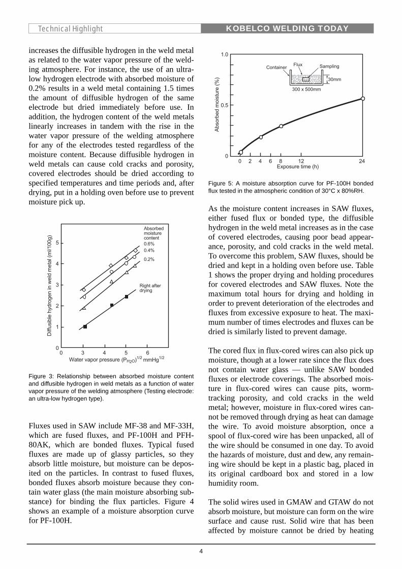
SAW granular flux as well as the fluxes used incovered electrodes and flux-core wires pick upmoisture during storage and usage at a low or highrate depending on ambient temperature and rela-tive humidity. Figure 2 compares the effects ofambient temperature and relative humidity, or the
water vapor pressure, on the moisture absorptionrate of a moisture-resistant low-hydrogen electrode(such as LB-62UL, LB-62L, LB-80UL, and LB-116) and a conventional low-hydrogen electrode.Clearly, higher ambient temperature and relativehumidity results in higher rates of moisture absorp-tion for both types of low hydrogen electrodes,although they do differ in degree.
Figure 2: Moisture absorption curves of a moisture-resistantlow-hydrogen electrode and a conventional low-hydrogenelectrode as related to ambient temperature and relativehumidity (The water vapor pressure given in the parentheseswas calculated by using the relevant temperature and relativehumidity).
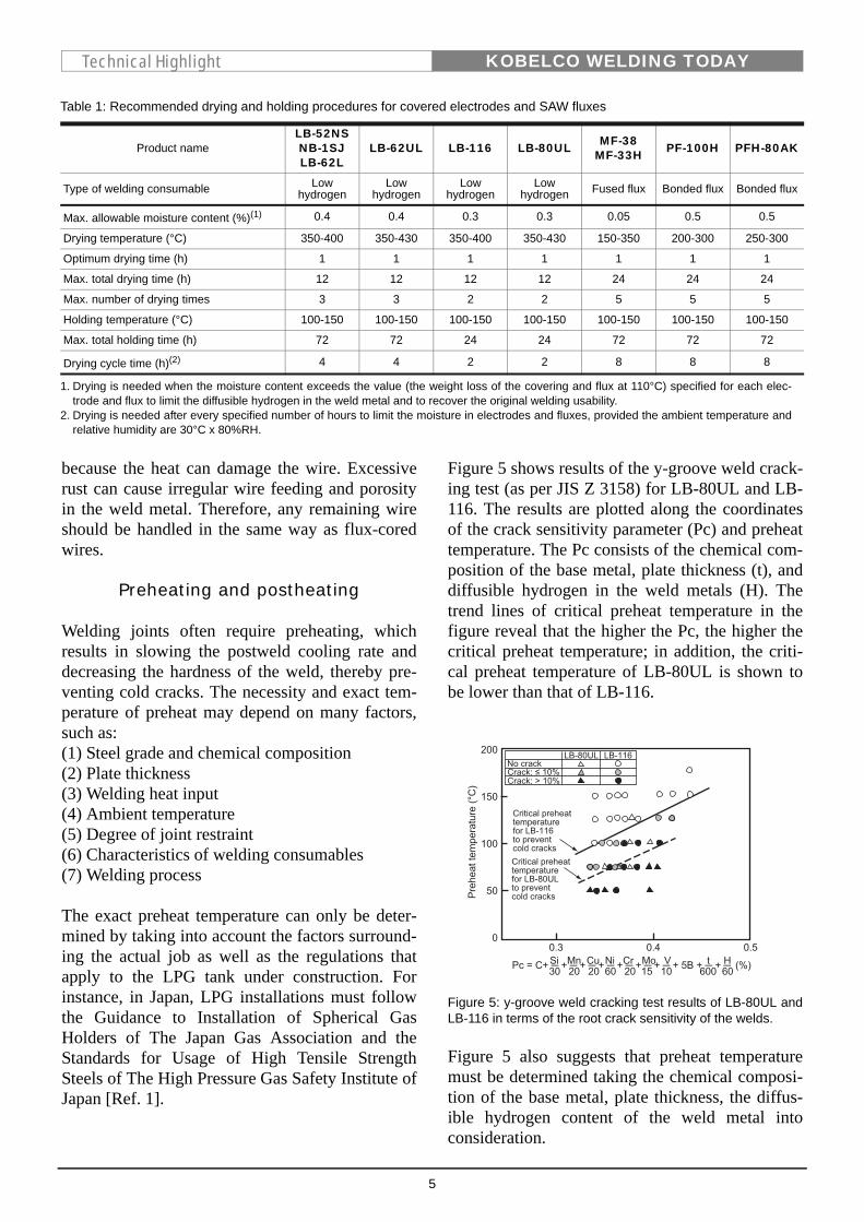
The absorbed moisture in an electrode can be asource of diffusible hydrogen in the weld metal.Figure 3 shows how the absorbed moisture
4
KOBELCO WELDING TODAYTechnical Highlight
increases the diffusible hydrogen in the weld metalas related to the water vapor pressure of the weld-ing atmosphere. For instance, the use of an ultra-low hydrogen electrode with absorbed moisture of0.2% results in a weld metal containing 1.5 timesthe amount of diffusible hydrogen of the sameelectrode but dried immediately before use. Inaddition, the hydrogen content of the weld metalslinearly increases in tandem with the rise in thewater vapor pressure of the welding atmospherefor any of the electrodes tested regardless of themoisture content. Because diffusible hydrogen inweld metals can cause cold cracks and porosity,covered electrodes should be dried according tospecified temperatures and time periods and, afterdrying, put in a holding oven before use to preventmoisture pick up.
Figure 3: Relationship between absorbed moisture contentand diffusible hydrogen in weld metals as a function of watervapor pressure of the welding atmosphere (Testing electrode:an ultra-low hydrogen type).
Fluxes used in SAW include MF-38 and MF-33H,which are fused fluxes, and PF-100H and PFH-80AK, which are bonded fluxes. Typical fusedfluxes are made up of glassy particles, so theyabsorb little moisture, but moisture can be depos-ited on the particles. In contrast to fused fluxes,bonded fluxes absorb moisture because they con-tain water glass (the main moisture absorbing sub-stance) for binding the flux particles. Figure 4shows an example of a moisture absorption curvefor PF-100H.
Figure 5: A moisture absorption curve for PF-100H bondedflux tested in the atmospheric condition of 30°C x 80%RH.
As the moisture content increases in SAW fluxes,either fused flux or bonded type, the diffusiblehydrogen in the weld metal increases as in the caseof covered electrodes, causing poor bead appear-ance, porosity, and cold cracks in the weld metal.To overcome this problem, SAW fluxes, should bedried and kept in a holding oven before use. Table1 shows the proper drying and holding proceduresfor covered electrodes and SAW fluxes. Note themaximum total hours for drying and holding inorder to prevent deterioration of the electrodes andfluxes from excessive exposure to heat. The maxi-mum number of times electrodes and fluxes can bedried is similarly listed to prevent damage.
The cored flux in flux-cored wires can also pick upmoisture, though at a lower rate since the flux doesnot contain water glass — unlike SAW bondedfluxes or electrode coverings. The absorbed mois-ture in flux-cored wires can cause pits, worm-tracking porosity, and cold cracks in the weldmetal; however, moisture in flux-cored wires can-not be removed through drying as heat can damagethe wire. To avoid moisture absorption, once aspool of flux-cored wire has been unpacked, all ofthe wire should be consumed in one day. To avoidthe hazards of moisture, dust and dew, any remain-ing wire should be kept in a plastic bag, placed inits original cardboard box and stored in a lowhumidity room.
The solid wires used in GMAW and GTAW do notabsorb moisture, but moisture can form on the wiresurface and cause rust. Solid wire that has beenaffected by moisture cannot be dried by heating
5
KOBELCO WELDING TODAYTechnical Highlight
because the heat can damage the wire. Excessiverust can cause irregular wire feeding and porosityin the weld metal. Therefore, any remaining wireshould be handled in the same way as flux-coredwires.
Preheating and postheating
Welding joints often require preheating, whichresults in slowing the postweld cooling rate anddecreasing the hardness of the weld, thereby pre-venting cold cracks. The necessity and exact tem-perature of preheat may depend on many factors,such as:(1) Steel grade and chemical composition(2) Plate thickness(3) Welding heat input(4) Ambient temperature(5) Degree of joint restraint(6) Characteristics of welding consumables(7) Welding process
The exact preheat temperature can only be deter-mined by taking into account the factors surround-ing the actual job as well as the regulations thatapply to the LPG tank under construction. Forinstance, in Japan, LPG installations must followthe Guidance to Installation of Spherical GasHolders of The Japan Gas Association and theStandards for Usage of High Tensile StrengthSteels of The High Pressure Gas Safety Institute ofJapan [Ref. 1].
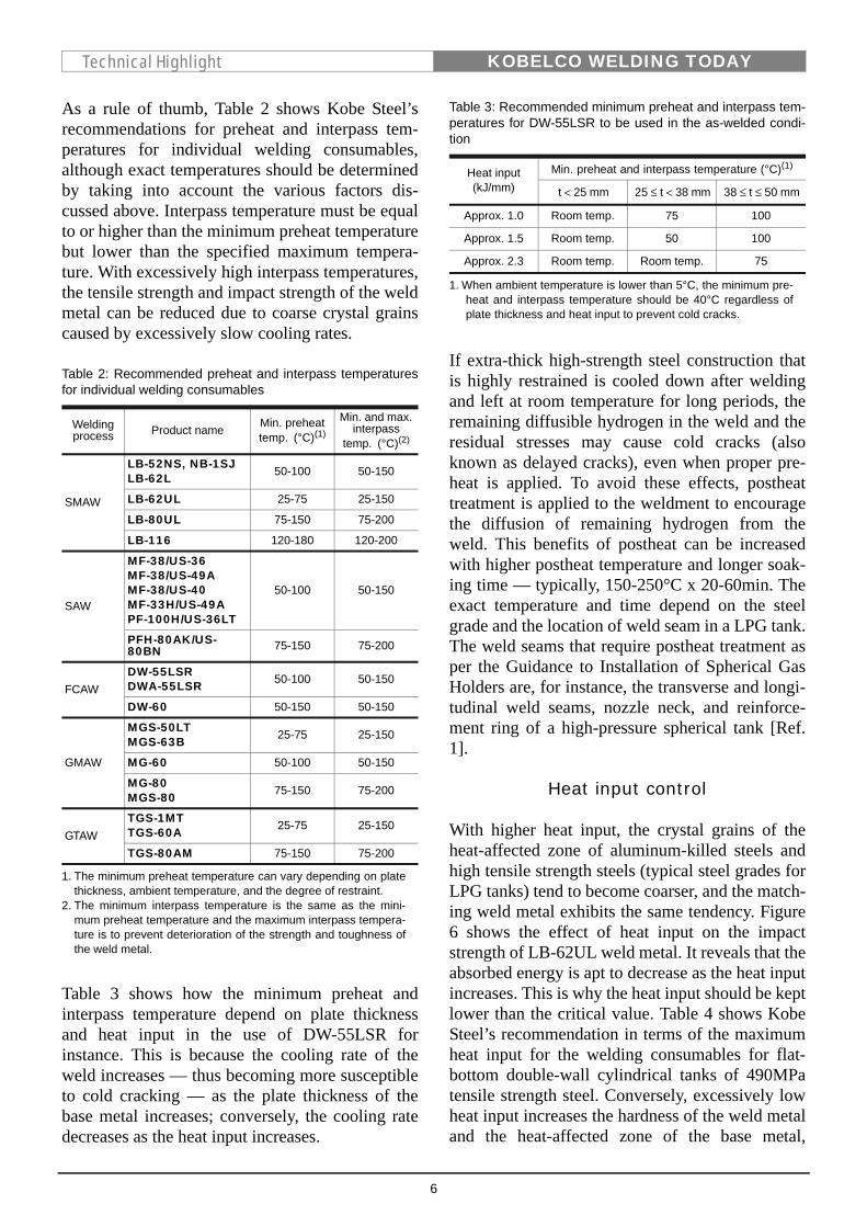
Figure 5 shows results of the y-groove weld crack-ing test (as per JIS Z 3158) for LB-80UL and LB-116. The results are plotted along the coordinatesof the crack sensitivity parameter (Pc) and preheattemperature. The Pc consists of the chemical com-position of the base metal, plate thickness (t), anddiffusible hydrogen in the weld metals (H). Thetrend lines of critical preheat temperature in thefigure reveal that the higher the Pc, the higher thecritical preheat temperature; in addition, the criti-cal preheat temperature of LB-80UL is shown tobe lower than that of LB-116.
Figure 5: y-groove weld cracking test results of LB-80UL andLB-116 in terms of the root crack sensitivity of the welds.
Figure 5 also suggests that preheat temperaturemust be determined taking the chemical composi-tion of the base metal, plate thickness, the diffus-ible hydrogen content of the weld metal intoconsideration.
Table 1: Recommended drying and holding procedures for covered electrodes and SAW fluxes
Product nameLB-52NSNB-1SJLB-62L
LB-62UL LB-116 LB-80UL MF-38MF-33H PF-100H PFH-80AK
Type of welding consumable Low hydrogen
Low hydrogen
Low hydrogen
Low hydrogen Fused flux Bonded flux Bonded flux
Max. allowable moisture content (%)(1) 0.4 0.4 0.3 0.3 0.05 0.5 0.5
Drying temperature (°C) 350-400 350-430 350-400 350-430 150-350 200-300 250-300
Optimum drying time (h) 1 1 1 1 1 1 1
Max. total drying time (h) 12 12 12 12 24 24 24
Max. number of drying times 3 3 2 2 5 5 5
Holding temperature (°C) 100-150 100-150 100-150 100-150 100-150 100-150 100-150
Max. total holding time (h) 72 72 24 24 72 72 72
Drying cycle time (h)(2) 4 4 2 2 8 8 8
1. Drying is needed when the moisture content exceeds the value (the weight loss of the covering and flux at 110°C) specified for each elec-trode and flux to limit the diffusible hydrogen in the weld metal and to recover the original welding usability.
2. Drying is needed after every specified number of hours to limit the moisture in electrodes and fluxes, provided the ambient temperature andrelative humidity are 30°C x 80%RH.
6
KOBELCO WELDING TODAYTechnical Highlight
As a rule of thumb, Table 2 shows Kobe Steel’srecommendations for preheat and interpass tem-peratures for individual welding consumables,although exact temperatures should be determinedby taking into account the various factors dis-cussed above. Interpass temperature must be equalto or higher than the minimum preheat temperaturebut lower than the specified maximum tempera-ture. With excessively high interpass temperatures,the tensile strength and impact strength of the weldmetal can be reduced due to coarse crystal grainscaused by excessively slow cooling rates.
Table 3 shows how the minimum preheat andinterpass temperature depend on plate thicknessand heat input in the use of DW-55LSR forinstance. This is because the cooling rate of theweld increases — thus becoming more susceptibleto cold cracking — as the plate thickness of thebase metal increases; conversely, the cooling ratedecreases as the heat input increases.
If extra-thick high-strength steel construction thatis highly restrained is cooled down after weldingand left at room temperature for long periods, theremaining diffusible hydrogen in the weld and theresidual stresses may cause cold cracks (alsoknown as delayed cracks), even when proper pre-heat is applied. To avoid these effects, postheattreatment is applied to the weldment to encouragethe diffusion of remaining hydrogen from theweld. This benefits of postheat can be increasedwith higher postheat temperature and longer soak-ing time — typically, 150-250°C x 20-60min. Theexact temperature and time depend on the steelgrade and the location of weld seam in a LPG tank.The weld seams that require postheat treatment asper the Guidance to Installation of Spherical GasHolders are, for instance, the transverse and longi-tudinal weld seams, nozzle neck, and reinforce-ment ring of a high-pressure spherical tank [Ref.1].
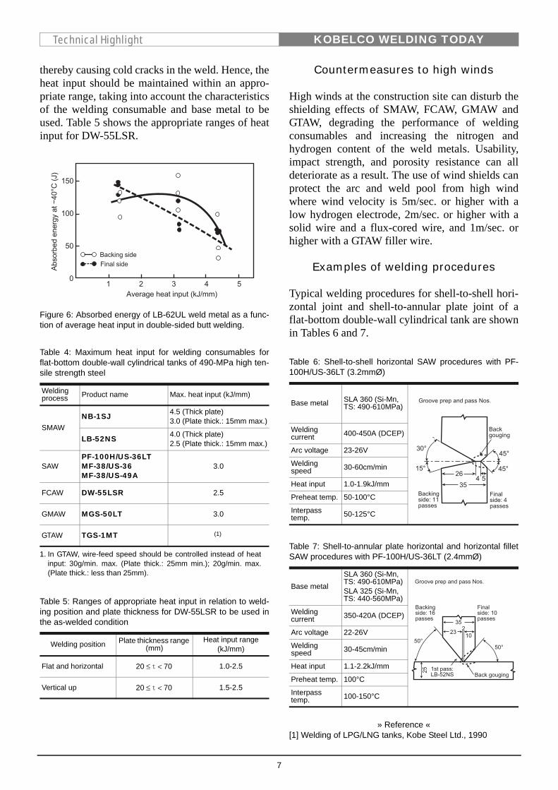
Heat input control
With higher heat input, the crystal grains of theheat-affected zone of aluminum-killed steels andhigh tensile strength steels (typical steel grades forLPG tanks) tend to become coarser, and the match-ing weld metal exhibits the same tendency. Figure6 shows the effect of heat input on the impactstrength of LB-62UL weld metal. It reveals that theabsorbed energy is apt to decrease as the heat inputincreases. This is why the heat input should be keptlower than the critical value. Table 4 shows KobeSteel’s recommendation in terms of the maximumheat input for the welding consumables for flat-bottom double-wall cylindrical tanks of 490MPatensile strength steel. Conversely, excessively lowheat input increases the hardness of the weld metaland the heat-affected zone of the base metal,
Table 2: Recommended preheat and interpass temperaturesfor individual welding consumables
Welding process Product name Min. preheat
temp. (°C)(1)
1. The minimum preheat temperature can vary depending on platethickness, ambient temperature, and the degree of restraint.
Min. and max. interpass
temp. (°C)(2)
2. The minimum interpass temperature is the same as the mini-mum preheat temperature and the maximum interpass tempera-ture is to prevent deterioration of the strength and toughness ofthe weld metal.
SMAW
LB-52NS, NB-1SJLB-62L 50-100 50-150
LB-62UL 25-75 25-150
LB-80UL 75-150 75-200
LB-116 120-180 120-200
SAW
MF-38/US-36MF-38/US-49AMF-38/US-40MF-33H/US-49APF-100H/US-36LT
50-100 50-150
PFH-80AK/US-80BN 75-150 75-200
FCAWDW-55LSRDWA-55LSR 50-100 50-150
DW-60 50-150 50-150
GMAW
MGS-50LTMGS-63B 25-75 25-150
MG-60 50-100 50-150
MG-80MGS-80 75-150 75-200
GTAWTGS-1MTTGS-60A 25-75 25-150
TGS-80AM 75-150 75-200
Table 3: Recommended minimum preheat and interpass tem-peratures for DW-55LSR to be used in the as-welded condi-tion
Heat input(kJ/mm)
Min. preheat and interpass temperature (°C)(1)
mm mm mm
Approx. 1.0 Room temp. 75 100
Approx. 1.5 Room temp. 50 100
Approx. 2.3 Room temp. Room temp. 75
1. When ambient temperature is lower than 5°C, the minimum pre-heat and interpass temperature should be 40°C regardless ofplate thickness and heat input to prevent cold cracks.
t 25< 25 t 38<≤ 38 t 50≤ ≤
7
KOBELCO WELDING TODAYTechnical Highlight
thereby causing cold cracks in the weld. Hence, theheat input should be maintained within an appro-priate range, taking into account the characteristicsof the welding consumable and base metal to beused. Table 5 shows the appropriate ranges of heatinput for DW-55LSR.
Figure 6: Absorbed energy of LB-62UL weld metal as a func-tion of average heat input in double-sided butt welding.
Countermeasures to high winds
High winds at the construction site can disturb theshielding effects of SMAW, FCAW, GMAW andGTAW, degrading the performance of weldingconsumables and increasing the nitrogen andhydrogen content of the weld metals. Usability,impact strength, and porosity resistance can alldeteriorate as a result. The use of wind shields canprotect the arc and weld pool from high windwhere wind velocity is 5m/sec. or higher with alow hydrogen electrode, 2m/sec. or higher with asolid wire and a flux-cored wire, and 1m/sec. orhigher with a GTAW filler wire.
Examples of welding procedures
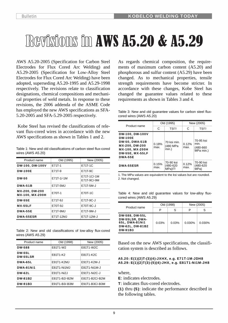
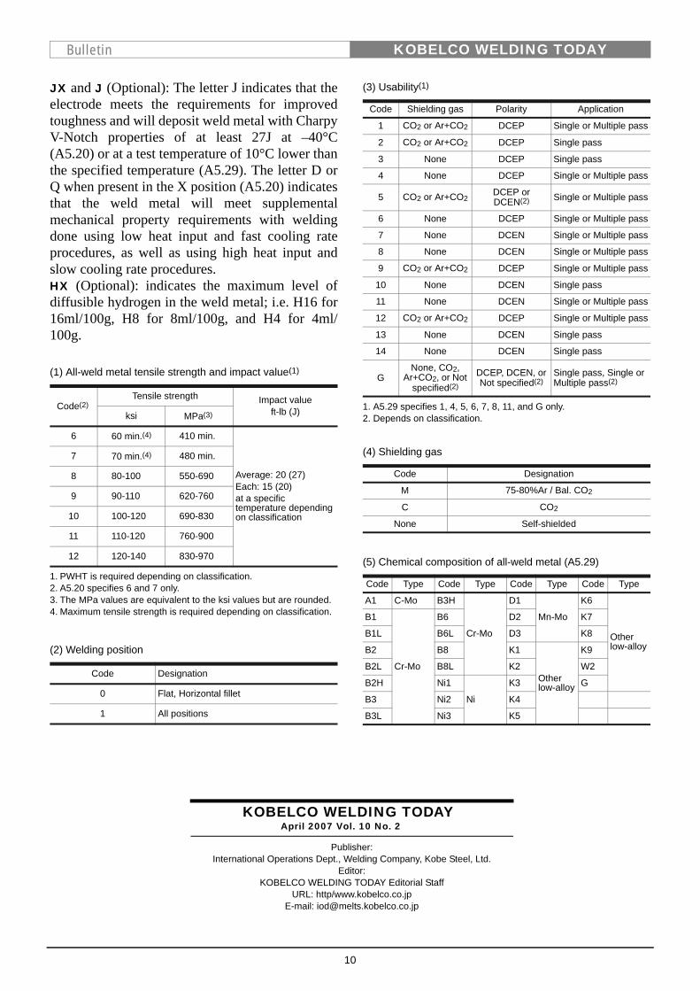
Typical welding procedures for shell-to-shell hori-zontal joint and shell-to-annular plate joint of aflat-bottom double-wall cylindrical tank are shownin Tables 6 and 7.
» Reference «[1] Welding of LPG/LNG tanks, Kobe Steel Ltd., 1990
Table 4: Maximum heat input for welding consumables forflat-bottom double-wall cylindrical tanks of 490-MPa high ten-sile strength steel
Welding process Product name Max. heat input (kJ/mm)
SMAWNB-1SJ 4.5 (Thick plate)
3.0 (Plate thick.: 15mm max.)
LB-52NS 4.0 (Thick plate)2.5 (Plate thick.: 15mm max.)
SAWPF-100H/US-36LTMF-38/US-36MF-38/US-49A
3.0
FCAW DW-55LSR 2.5
GMAW MGS-50LT 3.0
GTAW TGS-1MT (1)
1. In GTAW, wire-feed speed should be controlled instead of heatinput: 30g/min. max. (Plate thick.: 25mm min.); 20g/min. max.(Plate thick.: less than 25mm).
Table 5: Ranges of appropriate heat input in relation to weld-ing position and plate thickness for DW-55LSR to be used inthe as-welded condition
Welding position Plate thickness range (mm)
Heat input range (kJ/mm)
Flat and horizontal 1.0-2.5
Vertical up 1.5-2.5
20 t 70<≤
20 t 70<≤
Table 6: Shell-to-shell horizontal SAW procedures with PF-100H/US-36LT (3.2mmØ)
Base metal SLA 360 (Si-Mn, TS: 490-610MPa)
Welding current 400-450A (DCEP)
Arc voltage 23-26V
Welding speed 30-60cm/min
Heat input 1.0-1.9kJ/mm
Preheat temp. 50-100°C
Interpass temp. 50-125°C
Table 7: Shell-to-annular plate horizontal and horizontal filletSAW procedures with PF-100H/US-36LT (2.4mmØ)
Base metalSLA 360 (Si-Mn, TS: 490-610MPa)SLA 325 (Si-Mn, TS: 440-560MPa)
Welding current 350-420A (DCEP)
Arc voltage 22-26V
Welding speed 30-45cm/min
Heat input 1.1-2.2kJ/mm
Preheat temp. 100°C
Interpass temp. 100-150°C
8
KOBELCO WELDING TODAYQuestion & Answer
Question:We weld a variety of galvanized steel sheets bysemi-automatic CO2 welding. However we have ahard time with postweld treatment and repair,because pits occur often and a lot of spatter is gen-erated. Could you please explain how porosity andspatter generate with galvanized steel sheets andrecommend a good welding wire to solve theseproblems?
Answer:Galvanized steel sheets are widely used in manysteel structures like cars, steel towers, bridges andbuildings because of their cost-effectiveness due toexcellent corrosion resistance and rust prevention.They include hot-dip galvanized steels, 5%Al-alloyed hot-dip galvanized steels, 55%Al-alloyedhot-dip galvanized steels, electrogalvanized steels,and other galvanized steels.
The weldability of these steels is related to theamount of zinc coating (g/m2). The thicker the zinccoating, the more the porosity (pits and blowholes)and spatter that result in arc welding. Porosity canbe understood by noting that the zinc coatingdecomposes in the arc heat and that the zinc vapor-izes at around 900°C to become a gas, causingbubbles in the weld pool and porosity in the weldmetal. As to the increase of spatter, The force ofthe zinc vapor jet against the arc likely causes the
metal droplet transfer to become unstable, therebyexpelling the metal droplets outside the arc as spat-ter.
A variety of porosity-resistant low-spatter weldingwires for galvanized steel sheets have been devel-oped. These wires have sophisticated chemicalcompositions that suppress the growth of gas bub-bles trapped in the weld pool and stabilize metaldroplet transfer.
Cars, electric machinery, office equipment, andvending machines typically adopt electro-galva-nized steel sheets with 50g/m2 or less of coatingand alloyed hot-dip galvanized steel sheets with40-100g/m2 of coating. For these thin-coated steelsheets, solid wires, such as MG-1Z (for CO2 gasshielding), MIX-1Z (for Ar-CO2 mixed gas shield-ing), and MIX-1TS (for Ar-CO2 mixed gas shield-ing and pulsed current) are recommended.
Table 1 shows the applications for and characteris-tics of the above-mentioned welding wires. If youtake into account the shielding gas compositionand the power source output characteristics whenselecting a wire, you will be able to perform highlyefficient welding resulting in high quality welds,less porosity, and low spatter.
Table 1: Solid wires for gas metal arc welding of galvanized steel sheets
Name of Wire Diameter (mm) AWS Standard Application Characteristics
MG-1Z 1.0, 1.2 A5.18ER70S-G
Parts for cars, rolling stock,housings, electric machinery
For CO2 gas shielding.Suitable for sheets with a zinc coating of up to about 60g/m2.
MIX-1Z 1.0, 1.2 A5.18ER70S-G
For Ar+CO2 mixed gas shielding. Pulsed current brings about less porosity.
MIX-1TS 1.2 A5.18ER70S-G
For Ar+CO2 mixed gas shielding with pulsed current.Extremely less porosity and spatter.
9
KOBELCO WELDING TODAYBulletin
AWS A5.20-2005 (Specification for Carbon SteelElectrodes for Flux Cored Arc Welding) andA5.29-2005 (Specification for Low-Alloy SteelElectrodes for Flux Cored Arc Welding) have beenadopted, superseding A5.20-1995 and A5.29-1998respectively. The revisions relate to classificationdesignations, chemical compositions and mechani-cal properties of weld metals. In response to theserevisions, the 2006 addenda of the ASME Codehas employed the new AWS specifications as SFA-5.20-2005 and SFA-5.29-2005 respectively.
Kobe Steel has revised the classifications of rele-vant flux-cored wires in accordance with the newAWS specifications as shown in Tables 1 and 2.
As regards chemical composition, the require-ments of maximum carbon content (A5.20) andphosphorous and sulfur content (A5.29) have beenchanged. As to mechanical properties, tensilestrength requirements have become stricter. Inaccordance with these changes, Kobe Steel haschanged the guarantee values related to theserequirements as shown in Tables 3 and 4.
Based on the new AWS specifications, the classifi-cation system is described as follows.
A5.20: E(1)(2)T-(3)(4)-JXHX, e.g. E71T-1M-JDH8A5.29: E(1)(2)T(3)-(5)(4)-JHX, e.g. E81T1-Ni1M-JH8
where,E: indicates electrodes.T: indicates flux-cored electrodes.(1) thru (5): indicate the performance described inthe following tables.
Table 1: New and old classifications of carbon steel flux-coredwires (AWS A5.20)
Product name Old (1995) New (2005)
DW-100, DW-100V E71T-1 E71T-1C
DW-100E E71T-9 E71T-9C
DW-50 E71T-1/-1M E71T-1C/-1ME71T-9C/-9M
DWA-51B E71T-5MJ E71T-5M-J
MX-200, DW-200MX-100, MX-200H E70T-1 E70T-1C
DW-55E E71T-9J E71T-9C-J
MX-55LF E70T-9J E70T-9C-J
DWA-55E E71T-9MJ E71T-9M-J
DWA-55ESR E71T-12MJ E71T-12M-J
Table 2: New and old classifications of low-alloy flux-coredwires (AWS A5.29)
Product name Old (1998) New (2005)
DW-588 E81T1-W2 E81T1-W2C
DW-55LDW-55LSR E81T1-K2 E81T1-K2C
DWA-65L E91T1-K2MJ E91T1-K2M-J
DWA-81Ni1 E81T1-Ni1MJ E81T1-Ni1M-J
DW-62L E91T1-Ni2J E91T1-Ni2C-J
DW-81B2 E81T1-B2/-B2M E81T1-B2C/-B2M
DW-91B3 E91T1-B3/-B3M E91T1-B3C/-B3M
Table 3: New and old guarantee values for carbon steel flux-cored wires (AWS A5.20)
Product nameOld (1995) New (2005)
C TS(1)
1. The MPa values are equivalent to the ksi values but are rounded.
C TS(1)
DW-100, DW-100VDW-100EDW-50, DWA-51BMX-200, DW-200MX-100, MX-200HDW-55E, MX-55LFDWA-55E
0.18% max.
70 ksi min. (480 MPa min.)
0.12% max.
70-95 ksi min. (480-660 MPa min.)
DWA-55ESR 0.15% max.
70-90 ksi (480-620 MPa)(2)
2. Not changed.
0.12% max.
70-90 ksi (480-620 MPa)
Table 4: New and old guarantee values for low-alloy flux-cored wires (AWS A5.29)
Product nameOld (1998) New (2005)
P S P S
DW-588, DW-55LDW-55LSR, DWA-65L, DWA-81Ni1DW-62L, DW-81B2DW-91B3
0.03% 0.03% 0.030% 0.030%
10
KOBELCO WELDING TODAYBulletin
JX and J (Optional): The letter J indicates that theelectrode meets the requirements for improvedtoughness and will deposit weld metal with CharpyV-Notch properties of at least 27J at –40°C(A5.20) or at a test temperature of 10°C lower thanthe specified temperature (A5.29). The letter D orQ when present in the X position (A5.20) indicatesthat the weld metal will meet supplementalmechanical property requirements with weldingdone using low heat input and fast cooling rateprocedures, as well as using high heat input andslow cooling rate procedures.HX (Optional): indicates the maximum level ofdiffusible hydrogen in the weld metal; i.e. H16 for16ml/100g, H8 for 8ml/100g, and H4 for 4ml/100g.
1. A5.29 specifies 1, 4, 5, 6, 7, 8, 11, and G only.2. Depends on classification.
(1) All-weld metal tensile strength and impact value(1)
1. PWHT is required depending on classification.
Code(2)
2. A5.20 specifies 6 and 7 only.
Tensile strength Impact valueft-lb (J)ksi MPa(3)
3. The MPa values are equivalent to the ksi values but are rounded.
6 60 min.(4)
4. Maximum tensile strength is required depending on classification.
410 min.
Average: 20 (27)Each: 15 (20)at a specific temperature depending on classification
7 70 min.(4) 480 min.
8 80-100 550-690
9 90-110 620-760
10 100-120 690-830
11 110-120 760-900
12 120-140 830-970
(2) Welding position
Code Designation
0 Flat, Horizontal fillet
1 All positions
(3) Usability(1)
Code Shielding gas Polarity Application
1 CO2 or Ar+CO2 DCEP Single or Multiple pass
2 CO2 or Ar+CO2 DCEP Single pass
3 None DCEP Single pass
4 None DCEP Single or Multiple pass
5 CO2 or Ar+CO2DCEP or DCEN(2) Single or Multiple pass
6 None DCEP Single or Multiple pass
7 None DCEN Single or Multiple pass
8 None DCEN Single or Multiple pass
9 CO2 or Ar+CO2 DCEP Single or Multiple pass
10 None DCEN Single pass
11 None DCEN Single or Multiple pass
12 CO2 or Ar+CO2 DCEP Single or Multiple pass
13 None DCEN Single pass
14 None DCEN Single pass
GNone, CO2,
Ar+CO2, or Not specified(2)
DCEP, DCEN, or Not specified(2)
Single pass, Single or Multiple pass(2)
(4) Shielding gas
Code Designation
M 75-80%Ar / Bal. CO2
C CO2
None Self-shielded
(5) Chemical composition of all-weld metal (A5.29)
Code Type Code Type Code Type Code Type
A1 C-Mo B3H
Cr-Mo
D1
Mn-Mo
K6
Other low-alloy
B1
Cr-Mo
B6 D2 K7
B1L B6L D3 K8
B2 B8 K1
Other low-alloy
K9
B2L B8L K2 W2
B2H Ni1
Ni
K3 G
B3 Ni2 K4
B3L Ni3 K5
KOBELCO WELDING TODAYApril 2007 Vol. 10 No. 2
Publisher:International Operations Dept., Welding Company, Kobe Steel, Ltd.
Editor:KOBELCO WELDING TODAY Editorial Staff
URL: http/www.kobelco.co.jpE-mail: [email protected]