Embed Size (px)
DESCRIPTION
Fine screening and screens
Citation preview
Przesiewanie drobnoziarnowe i maszyny przesiewające
Fine screening and screens
Piotr WODZIŃSKI 1)
1) Prof. dr hab. inż.; Politechnika Łódzka; Wydział Inżynierii Procesowej i Ochrony Środowiska; Katedra Aparatury Procesowej;ul. Żwirki 36, 90-924 Łódź; tel.: (+ 48-42) 631-37-40, faks: (+ 48-42) 636-56-63
RECENZENCI: prof. zw. dr hab. inż. Kazimierz SZTABA; prof. dr hab. inż. Wiesław BLASCHKE
SummaryThis paper is dedicated to some problems of screening offine- and very fine-grained loose materials. This is the mostdifficult screening process (beside screening off wet ma-terials), which in industrial practice has not been solvedyet. As far as in the world industry typical single-planescreens are very popular (they are named, not very pre-cisely, the vibrating screens) with known process proper-ties, for screening of fine-grained material various screensare used which prove not always the most efficient inindustrial conditions.The present paper is debatable, and can be treated as acontribution to a slightly different approach to screeningthan that represented so far. Additionally, it presents somepractical recommendations which are important for finescreening process.Second part of the paper is dedicated to screening machi-nes developed by the author. These are design solutionsproposed mainly for screening of fine-grained materials. Inthis section the importance of correct feed supply to thescreen is discussed. Special attention is given to drives —mainly rotational (unbalanced shafts), on which the pro-cess efficiency depends greatly.
1. IntroductionScreening of fine-grained materials on sieves is
a process which differs from coarse-grain screening.The main difference lies in the presence of a layeron the sieve. The thickness of this layer exceeds se-veral times the diameter of an average grain in thefeed. This means that the behaviour of grains to bescreened in the layer on the sieve will depend on theinterrelations of individual grains — the phenome-non which is not observed in thin layers, i.e. suchones whose thickness does not exceed several dia-meters of an average grain.
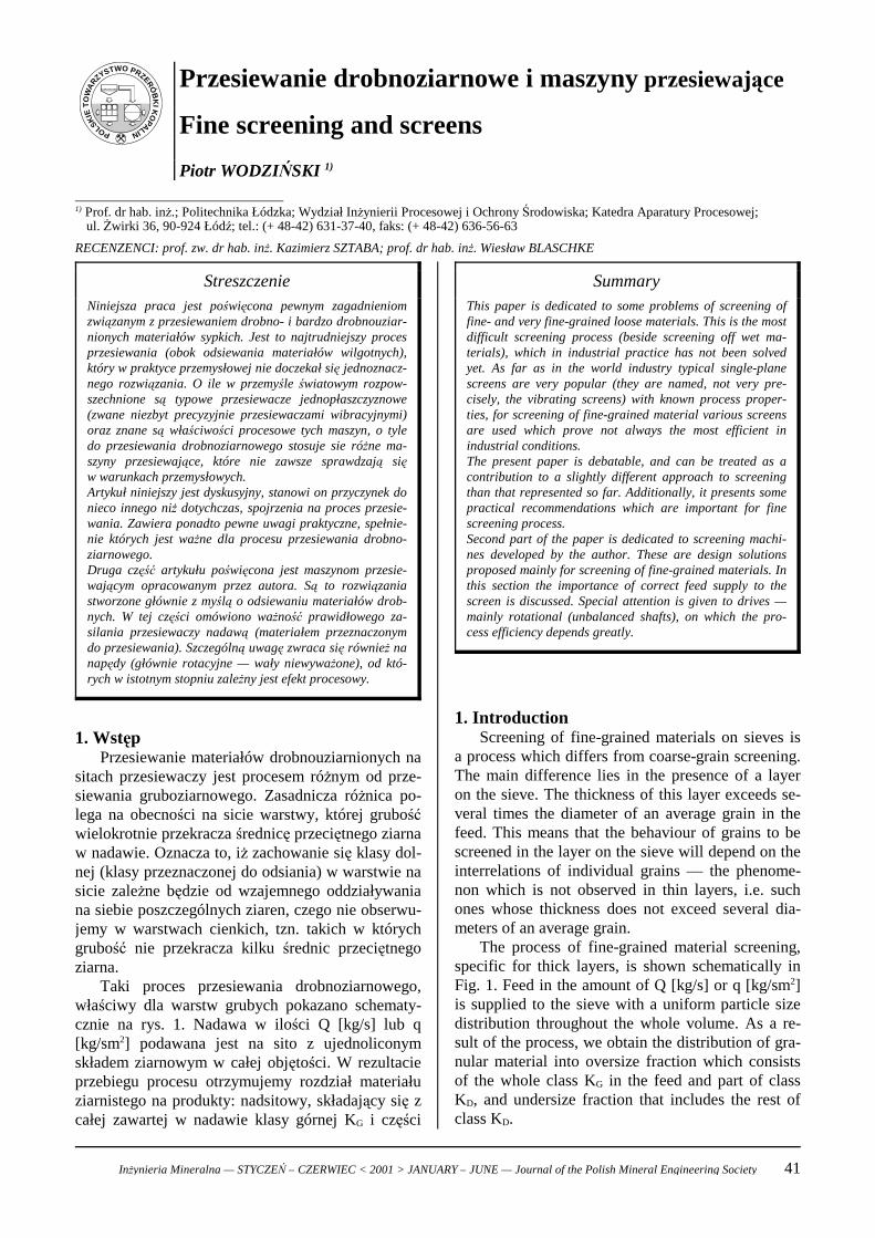
The process of fine-grained material screening,specific for thick layers, is shown schematically inFig. 1. Feed in the amount of Q [kg/s] or q [kg/sm2]is supplied to the sieve with a uniform particle sizedistribution throughout the whole volume. As a re-sult of the process, we obtain the distribution of gra-nular material into oversize fraction which consistsof the whole class KG in the feed and part of classKD, and undersize fraction that includes the rest ofclass KD.
StreszczenieNiniejsza praca jest poświęcona pewnym zagadnieniomzwiązanym z przesiewaniem drobno- i bardzo drobnouziar-nionych materiałów sypkich. Jest to najtrudniejszy procesprzesiewania (obok odsiewania materiałów wilgotnych),który w praktyce przemysłowej nie doczekał się jednoznacz-nego rozwiązania. O ile w przemyśle światowym rozpow-szechnione są typowe przesiewacze jednopłaszczyznowe(zwane niezbyt precyzyjnie przesiewaczami wibracyjnymi)oraz znane są właściwości procesowe tych maszyn, o tyledo przesiewania drobnoziarnowego stosuje sie różne ma-szyny przesiewające, które nie zawsze sprawdzają sięw warunkach przemysłowych.Artykuł niniejszy jest dyskusyjny, stanowi on przyczynek donieco innego niż dotychczas, spojrzenia na proces przesie-wania. Zawiera ponadto pewne uwagi praktyczne, spełnie-nie których jest ważne dla procesu przesiewania drobno-ziarnowego.Druga część artykułu poświęcona jest maszynom przesie-wającym opracowanym przez autora. Są to rozwiązaniastworzone głównie z myślą o odsiewaniu materiałów drob-nych. W tej części omówiono ważność prawidłowego za-silania przesiewaczy nadawą (materiałem przeznaczonymdo przesiewania). Szczególną uwagę zwraca się również nanapędy (głównie rotacyjne — wały niewyważone), od któ-rych w istotnym stopniu zależny jest efekt procesowy.
1. WstępPrzesiewanie materiałów drobnouziarnionych na
sitach przesiewaczy jest procesem różnym od prze-siewania gruboziarnowego. Zasadnicza różnica po-lega na obecności na sicie warstwy, której grubośćwielokrotnie przekracza średnicę przeciętnego ziarnaw nadawie. Oznacza to, iż zachowanie się klasy dol-nej (klasy przeznaczonej do odsiania) w warstwie nasicie zależne będzie od wzajemnego oddziaływaniana siebie poszczególnych ziaren, czego nie obserwu-jemy w warstwach cienkich, tzn. takich w którychgrubość nie przekracza kilku średnic przeciętnegoziarna.
Taki proces przesiewania drobnoziarnowego,właściwy dla warstw grubych pokazano schematy-cznie na rys. 1. Nadawa w ilości Q [kg/s] lub q[kg/sm2] podawana jest na sito z ujednoliconymskładem ziarnowym w całej objętości. W rezultacieprzebiegu procesu otrzymujemy rozdział materiałuziarnistego na produkty: nadsitowy, składający się zcałej zawartej w nadawie klasy górnej KG i części
Inżynieria Mineralna — STYCZEŃ – CZERWIEC < 2001 > JANUARY – JUNE — Journal of the Polish Mineral Engineering Society 41
POLSKIE
TO
WA
RZYSTWO PRZERÓ
BK
I KO
PALIN
In the screening process two types of resistanceare distinguished: resistance of the layer (taken asa difficulty in segregating the layer) and sieve re-sistance (difficulty of grain transition through thesieve mesh). The layer resistance is more important— it determines the process efficiency. To minimisethe layer resistance, a proper vibrating motion of thescreen should be applied. Figure 1 shows differentscreen trajectories: a – linear, b – circular, c – elli-ptical, d – complex (double frequency), e – circling,f – non-linear, spatial.
klasy dolnej KD, oraz podsitowy, zawierający resztęklasy dolnej KD.
W procesie przesiewania wyróżniamy dwa opo-ry: opór warstwy (rozumiany jako trudność w roz-segregowaniu warstwy) i opór sita (rozumiany jakotrudność przejścia ziaren przez otwory sitowe). De-cydujący jest opór warstwy i to głównie od niegozależna jest skuteczna wydajność procesu. Aby zmi-nimalizować opór warstwy, należy zastosować odpo-wiedni ruch drgający maszyny przesiewającej. Narys. 1 pokazano różne trajektorie ruchu przesiewa-czy: a – liniowy, b – kołowy, c – eliptyczny, d – zło-żony (podwójnej częstości), e – zataczający, f – nie-liniowy, przestrzenny.
Fig. 1Screening mechanism and sieve trajectories
______________
Rys. 1Mechanizm przesiewania i tory sit______________
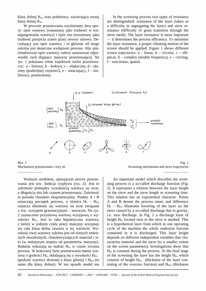
An important model which describes the scree-ning process is a so-called discharge function (Fig.2). It represents a relation between the layer heighton the sieve and the sieve length or screening time.This relation has an exponential character. PointsA and B denote the process onset, and differenceHP – HPA illustrates lowering of the layer on thesieve caused by a so-called discharge due to gravity,i.e. zero discharge. In Fig. 2 a discharge layer ofheight HW located next to the sieve is marked. Thisis a hypothetical layer from which in one operatingcycle of the machine the whole undersize fractioncontained in it is discharged. This layer heightdepends on different independent variables that cha-racterise material and the sieve (to a smaller extenton the screen parameters). Investigations show thatHW is constant during the process. At the final stageof the screening the layer has the height HK, whichconsists of height HKG (thickness of the layer con-sisting of the oversize fraction) and HKD (thickness
Ważnym modelem, opisującym proces przesie-wania jest tzw. funkcja wypływu (rys. 2). Jest tozależność pomiędzy wysokością warstwy na sicie,a długością sita lub czasem przesiewania. Zależnośćta posiada charakter eksponencjalny. Punkty A i Boznaczają początek procesu, a różnica HP – HPA
oznacza obniżenie się warstwy na sicie związanez tzw. wysypem grawitacyjnym – zerowym. Na rys.2 zaznaczono przysitową warstwę wysypową o wy-sokości HW. Jest to taka hipotetyczna warstwa,z której w jednym cyklu pracy maszyny wysypujesię cała klasa dolna zawarta w tej warstwie. Wy-sokość owej warstwy zależna jest od różnych zmien-nych niezależnych, charakteryzujących materiał i si-to (w mniejszym stopniu od parametrów maszyny).Badania wskazują na stałość HW w czasie trwaniaprocesu. W końcowej fazie przesiewania mamy war-stwę o grubości HK, składającą się z wysokości HKG (grubość warstwy złożonej z klasy górnej) i HKD (tosamo dla klasy dolnej). W ten sposób model ten
42 Inżynieria Mineralna — STYCZEŃ – CZERWIEC < 2001 > JANUARY – JUNE — Journal of the Polish Mineral Engineering Society
of the layer consisting of the undersize). Thus, themodel reflects the final screening efficiency which isassumed depending on technology.
The discharge function has one more impor-tant feature: it can be determined empirically bystudying the process of laboratory-scale screening, atmaintaining basic similarity to an industrial process.This correlation in its mathematical notation hasonly two empirical parameters and only they aredetermined experimentally.
uwzględnia końcową sprawność przesiewania, którabywa zakładana, w zależności od technologii pro-cesu.
Funkcja wypływu posiada jeszcze jednąważną cechę: można ją określić empirycznie, ba-dając proces przesiewania laboratoryjnego, przy za-chowaniu podstawowych cech podobieństwa z pro-cesem przemysłowym. Korelacja ta posiada w swo-im zapisie matematycznym jedynie dwa parametryempiryczne i one właściwie podlegają doświadczal-nemu wyznaczeniu.
Fig 2Discharge function
______________
Rys 2Funkcja wypływu______________
2. Step sieveA known, though not checked idea specially
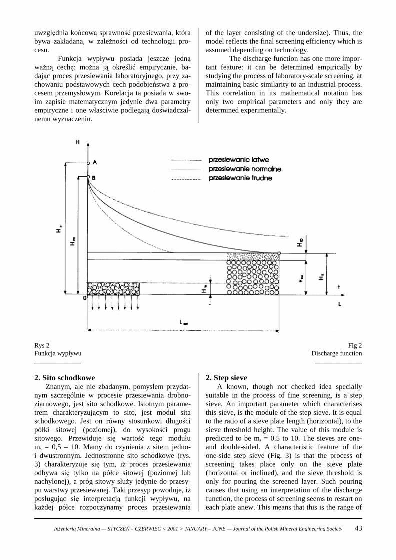
suitable in the process of fine screening, is a stepsieve. An important parameter which characterisesthis sieve, is the module of the step sieve. It is equalto the ratio of a sieve plate length (horizontal), to thesieve threshold height. The value of this module ispredicted to be ms = 0.5 to 10. The sieves are one-and double-sided. A characteristic feature of theone-side step sieve (Fig. 3) is that the process ofscreening takes place only on the sieve plate(horizontal or inclined), and the sieve threshold isonly for pouring the screened layer. Such pouringcauses that using an interpretation of the dischargefunction, the process of screening seems to restart oneach plate anew. This means that this is the range of
2. Sito schodkoweZnanym, ale nie zbadanym, pomysłem przydat-
nym szczególnie w procesie przesiewania drobno-ziarnowego, jest sito schodkowe. Istotnym parame-trem charakteryzującym to sito, jest moduł sitaschodkowego. Jest on równy stosunkowi długościpółki sitowej (poziomej), do wysokości progusitowego. Przewiduje się wartość tego modułums = 0,5 – 10. Mamy do czynienia z sitem jedno-i dwustronnym. Jednostronne sito schodkowe (rys.3) charakteryzuje się tym, iż proces przesiewaniaodbywa się tylko na półce sitowej (poziomej lubnachylonej), a próg sitowy służy jedynie do przesy-pu warstwy przesiewanej. Taki przesyp powoduje, iżposługując się interpretacją funkcji wypływu, nakażdej półce rozpoczynamy proces przesiewania
Inżynieria Mineralna — STYCZEŃ – CZERWIEC < 2001 > JANUARY – JUNE — Journal of the Polish Mineral Engineering Society 43
most intensive screening which is reflected by thelargest inclination of the discharge function to theaxis of abscissae (Fig. 3). In this region the under-size fraction is removed most efficiently from thebottom feed layer which moves along the sieve. Thatis why the step sieves are characterised by higherprocess efficiency as compared to analogous flatsieves.
jakby od nowa. Oznacza to, iż znajdujemy się w za-kresie najintensywniejszego odsiewu, co zobrazowa-ne jest największym nachyleniem funkcji wypływudo osi odciętych (rys. 3). W tym obszarze mamy doczynienia z najskuteczniejszym odpływem klasy dol-nej z warstwy nadawy, przesuwającej się wzdłuż si-ta. Dlatego sita schodkowe charakteryzują się wyż-szą skuteczną wydajnością procesową, w porówna-niu do analogicznych sit płaskich.
Fig. 3One-sided step sieves
______________
Rys. 3Sito schodkowe jednostronne______________
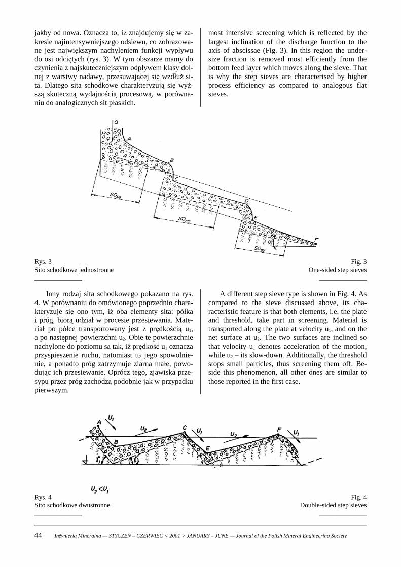
A different step sieve type is shown in Fig. 4. Ascompared to the sieve discussed above, its cha-racteristic feature is that both elements, i.e. the plateand threshold, take part in screening. Material istransported along the plate at velocity u1, and on thenet surface at u2. The two surfaces are inclined sothat velocity u1 denotes acceleration of the motion,while u2 – its slow-down. Additionally, the thresholdstops small particles, thus screening them off. Be-side this phenomenon, all other ones are similar tothose reported in the first case.
Inny rodzaj sita schodkowego pokazano na rys.4. W porównaniu do omówionego poprzednio chara-kteryzuje się ono tym, iż oba elementy sita: półkai próg, biorą udział w procesie przesiewania. Mate-riał po półce transportowany jest z prędkością u1,a po następnej powierzchni u2. Obie te powierzchnienachylone do poziomu są tak, iż prędkość u1 oznaczaprzyspieszenie ruchu, natomiast u2 jego spowolnie-nie, a ponadto próg zatrzymuje ziarna małe, powo-dując ich przesiewanie. Oprócz tego, zjawiska prze-sypu przez próg zachodzą podobnie jak w przypadkupierwszym.
Fig. 4Double-sided step sieves
______________
Rys. 4Sito schodkowe dwustronne______________
44 Inżynieria Mineralna — STYCZEŃ – CZERWIEC < 2001 > JANUARY – JUNE — Journal of the Polish Mineral Engineering Society
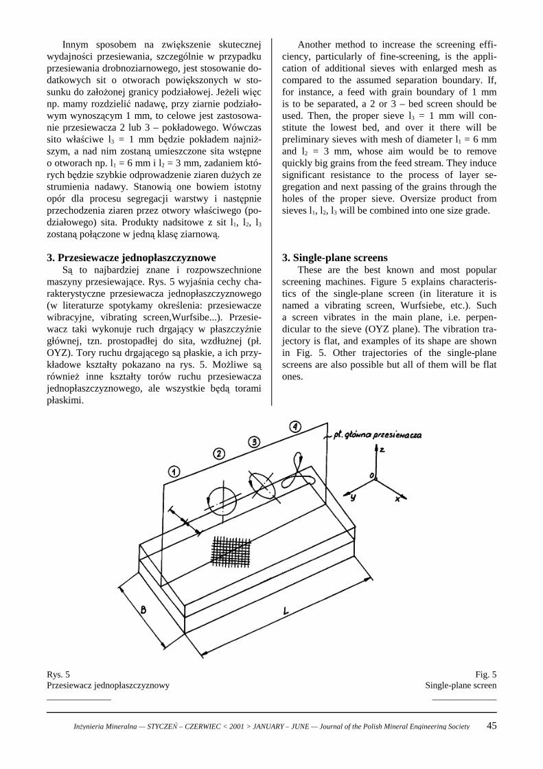
Another method to increase the screening effi-ciency, particularly of fine-screening, is the appli-cation of additional sieves with enlarged mesh ascompared to the assumed separation boundary. If,for instance, a feed with grain boundary of 1 mmis to be separated, a 2 or 3 – bed screen should beused. Then, the proper sieve l3 = 1 mm will con-stitute the lowest bed, and over it there will bepreliminary sieves with mesh of diameter l1 = 6 mmand l2 = 3 mm, whose aim would be to removequickly big grains from the feed stream. They inducesignificant resistance to the process of layer se-gregation and next passing of the grains through theholes of the proper sieve. Oversize product fromsieves l1, l2, l3 will be combined into one size grade.
3. Single-plane screensThese are the best known and most popular
screening machines. Figure 5 explains characteris-tics of the single-plane screen (in literature it isnamed a vibrating screen, Wurfsiebe, etc.). Sucha screen vibrates in the main plane, i.e. perpen-dicular to the sieve (OYZ plane). The vibration tra-jectory is flat, and examples of its shape are shownin Fig. 5. Other trajectories of the single-planescreens are also possible but all of them will be flatones.
Innym sposobem na zwiększenie skutecznejwydajności przesiewania, szczególnie w przypadkuprzesiewania drobnoziarnowego, jest stosowanie do-datkowych sit o otworach powiększonych w sto-sunku do założonej granicy podziałowej. Jeżeli więcnp. mamy rozdzielić nadawę, przy ziarnie podziało-wym wynoszącym 1 mm, to celowe jest zastosowa-nie przesiewacza 2 lub 3 – pokładowego. Wówczassito właściwe l3 = 1 mm będzie pokładem najniż-szym, a nad nim zostaną umieszczone sita wstępneo otworach np. l1 = 6 mm i l2 = 3 mm, zadaniem któ-rych będzie szybkie odprowadzenie ziaren dużych zestrumienia nadawy. Stanowią one bowiem istotnyopór dla procesu segregacji warstwy i następnieprzechodzenia ziaren przez otwory właściwego (po-działowego) sita. Produkty nadsitowe z sit l1, l2, l3
zostaną połączone w jedną klasę ziarnową.
3. Przesiewacze jednopłaszczyznoweSą to najbardziej znane i rozpowszechnione
maszyny przesiewające. Rys. 5 wyjaśnia cechy cha-rakterystyczne przesiewacza jednopłaszczyznowego(w literaturze spotykamy określenia: przesiewaczewibracyjne, vibrating screen,Wurfsibe...). Przesie-wacz taki wykonuje ruch drgający w płaszczyźniegłównej, tzn. prostopadłej do sita, wzdłużnej (pł.OYZ). Tory ruchu drgającego są płaskie, a ich przy-kładowe kształty pokazano na rys. 5. Możliwe sąrównież inne kształty torów ruchu przesiewaczajednopłaszczyznowego, ale wszystkie będą toramipłaskimi.
Fig. 5Single-plane screen
______________
Rys. 5Przesiewacz jednopłaszczyznowy______________
Inżynieria Mineralna — STYCZEŃ – CZERWIEC < 2001 > JANUARY – JUNE — Journal of the Polish Mineral Engineering Society 45
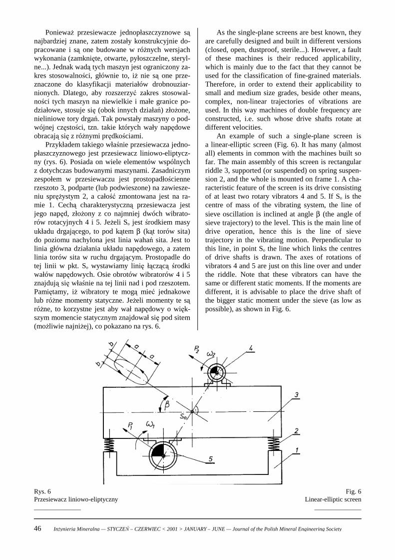
As the single-plane screens are best known, theyare carefully designed and built in different versions(closed, open, dustproof, sterile...). However, a faultof these machines is their reduced applicability,which is mainly due to the fact that they cannot beused for the classification of fine-grained materials.Therefore, in order to extend their applicability tosmall and medium size grades, beside other means,complex, non-linear trajectories of vibrations areused. In this way machines of double frequency areconstructed, i.e. such whose drive shafts rotate atdifferent velocities.
An example of such a single-plane screen isa linear-elliptic screen (Fig. 6). It has many (almostall) elements in common with the machines built sofar. The main assembly of this screen is rectangularriddle 3, supported (or suspended) on spring suspen-sion 2, and the whole is mounted on frame 1. A cha-racteristic feature of the screen is its drive consistingof at least two rotary vibrators 4 and 5. If So is thecentre of mass of the vibrating system, the line ofsieve oscillation is inclined at angle β (the angle ofsieve trajectory) to the level. This is the main line ofdrive operation, hence this is the line of sievetrajectory in the vibrating motion. Perpendicular tothis line, in point So the line which links the centresof drive shafts is drawn. The axes of rotations ofvibrators 4 and 5 are just on this line over and underthe riddle. Note that these vibrators can have thesame or different static moments. If the moments aredifferent, it is advisable to place the drive shaft ofthe bigger static moment under the sieve (as low aspossible), as shown in Fig. 6.
Ponieważ przesiewacze jednopłaszczyznowe sąnajbardziej znane, zatem zostały konstrukcyjnie do-pracowane i są one budowane w różnych wersjachwykonania (zamknięte, otwarte, pyłoszczelne, steryl-ne...). Jednak wadą tych maszyn jest ograniczony za-kres stosowalności, głównie to, iż nie są one prze-znaczone do klasyfikacji materiałów drobnouziar-nionych. Dlatego, aby rozszerzyć zakres stosowal-ności tych maszyn na niewielkie i małe granice po-działowe, stosuje się (obok innych działań) złożone,nieliniowe tory drgań. Tak powstały maszyny o pod-wójnej częstości, tzn. takie których wały napędoweobracają się z różnymi prędkościami.
Przykładem takiego właśnie przesiewacza jedno-płaszczyznowego jest przesiewacz liniowo-eliptycz-ny (rys. 6). Posiada on wiele elementów wspólnychz dotychczas budowanymi maszynami. Zasadniczymzespołem w przesiewaczu jest prostopadłościennerzeszoto 3, podparte (lub podwieszone) na zawiesze-niu sprężystym 2, a całość zmontowana jest na ra-mie 1. Cechą charakterystyczną przesiewacza jestjego napęd, złożony z co najmniej dwóch wibrato-rów rotacyjnych 4 i 5. Jeżeli So jest środkiem masyukładu drgającego, to pod kątem β (kąt torów sita)do poziomu nachylona jest linia wahań sita. Jest tolinia główna działania układu napędowego, a zatemlinia torów sita w ruchu drgającym. Prostopadle dotej linii w pkt. So wystawiamy linię łączącą środkiwałów napędowych. Osie obrotów wibratorów 4 i 5znajdują się właśnie na tej linii nad i pod rzeszotem.Pamiętamy, iż wibratory te mogą mieć jednakowelub różne momenty statyczne. Jeżeli momenty te sąróżne, to korzystne jest aby wał napędowy o więk-szym momencie statycznym znajdował się pod sitem(możliwie najniżej), co pokazano na rys. 6.
Fig. 6Linear-elliptic screen
______________
Rys. 6Przesiewacz liniowo-eliptyczny______________
46 Inżynieria Mineralna — STYCZEŃ – CZERWIEC < 2001 > JANUARY – JUNE — Journal of the Polish Mineral Engineering Society
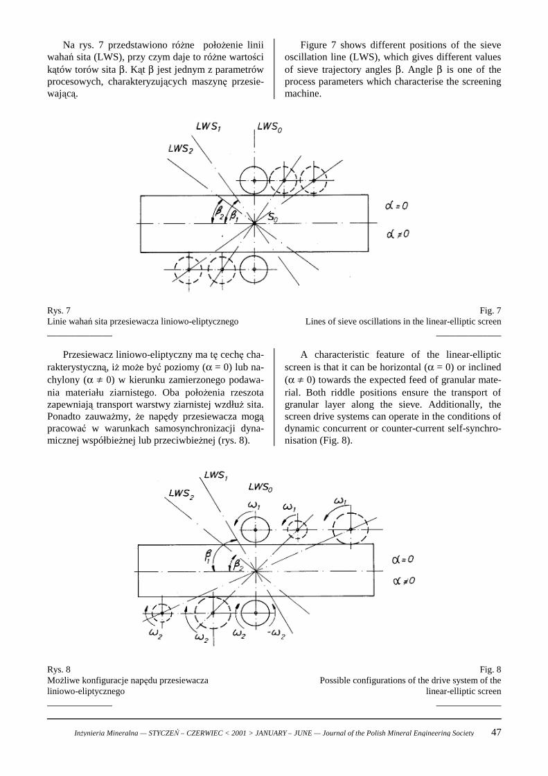
Figure 7 shows different positions of the sieveoscillation line (LWS), which gives different valuesof sieve trajectory angles β. Angle β is one of theprocess parameters which characterise the screeningmachine.
Na rys. 7 przedstawiono różne położenie liniiwahań sita (LWS), przy czym daje to różne wartościkątów torów sita β. Kąt β jest jednym z parametrówprocesowych, charakteryzujących maszynę przesie-wającą.
Fig. 7Lines of sieve oscillations in the linear-elliptic screen
______________
Rys. 7Linie wahań sita przesiewacza liniowo-eliptycznego______________
A characteristic feature of the linear-ellipticscreen is that it can be horizontal (α = 0) or inclined(α ! 0) towards the expected feed of granular mate-rial. Both riddle positions ensure the transport ofgranular layer along the sieve. Additionally, thescreen drive systems can operate in the conditions ofdynamic concurrent or counter-current self-synchro-nisation (Fig. 8).
Przesiewacz liniowo-eliptyczny ma tę cechę cha-rakterystyczną, iż może być poziomy (α = 0) lub na-chylony (α ! 0) w kierunku zamierzonego podawa-nia materiału ziarnistego. Oba położenia rzeszotazapewniają transport warstwy ziarnistej wzdłuż sita.Ponadto zauważmy, że napędy przesiewacza mogąpracować w warunkach samosynchronizacji dyna-micznej współbieżnej lub przeciwbieżnej (rys. 8).
Fig. 8Possible configurations of the drive system of the
linear-elliptic screen______________
Rys. 8Możliwe konfiguracje napędu przesiewaczaliniowo-eliptycznego______________
Inżynieria Mineralna — STYCZEŃ – CZERWIEC < 2001 > JANUARY – JUNE — Journal of the Polish Mineral Engineering Society 47
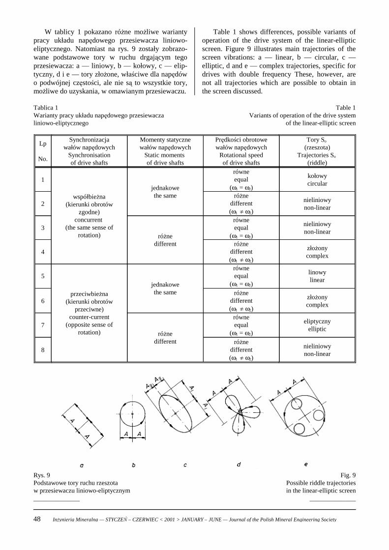
Table 1 shows differences, possible variants ofoperation of the drive system of the linear-ellipticscreen. Figure 9 illustrates main trajectories of thescreen vibrations: a — linear, b — circular, c —elliptic, d and e — complex trajectories, specific fordrives with double frequency These, however, arenot all trajectories which are possible to obtain inthe screen discussed.
W tablicy 1 pokazano różne możliwe wariantypracy układu napędowego przesiewacza liniowo-eliptycznego. Natomiast na rys. 9 zostały zobrazo-wane podstawowe tory w ruchu drgającym tegoprzesiewacza: a — liniowy, b — kołowy, c — elip-tyczny, d i e — tory złożone, właściwe dla napędówo podwójnej częstości, ale nie są to wszystkie tory,możliwe do uzyskania, w omawianym przesiewaczu.
Table 1Variants of operation of the drive system
of the linear-elliptic screen
Tablica 1 Warianty pracy układu napędowego przesiewaczaliniowo-eliptycznego
nieliniowynon-linear
różnedifferent(ω1 ! ω2)
8
eliptycznyelliptic
równeequal
(ω1 = ω2)różnedifferent
7
złożonycomplex
różnedifferent(ω1 ! ω2)
6
linowylinear
równeequal
(ω1 = ω2)jednakowethe sameprzeciwbieżna
(kierunki obrotówprzeciwne)
counter-current(opposite sense of
rotation)
5
złożonycomplex
różnedifferent(ω1 ! ω2)
4
nieliniowynon-linear
równeequal
(ω1 = ω2)różnedifferent
3
nieliniowynon-linear
różnedifferent(ω1 ! ω2)
2
kołowycircular
równeequal
(ω1 = ω2)jednakowethe samewspółbieżna
(kierunki obrotówzgodne)
concurrent (the same sense of
rotation)
1
Tory So (rzeszota)
Trajectories So (riddle)
Prędkości obrotowewałów napędowych
Rotational speedof drive shafts
Momenty statycznewałów napędowych
Static moments of drive shafts
Synchronizacjawałów napędowych
Synchronisationof drive shafts
Lp
No.
Fig. 9Possible riddle trajectoriesin the linear-elliptic screen
______________
Rys. 9Podstawowe tory ruchu rzeszotaw przesiewaczu liniowo-eliptycznym______________
48 Inżynieria Mineralna — STYCZEŃ – CZERWIEC < 2001 > JANUARY – JUNE — Journal of the Polish Mineral Engineering Society
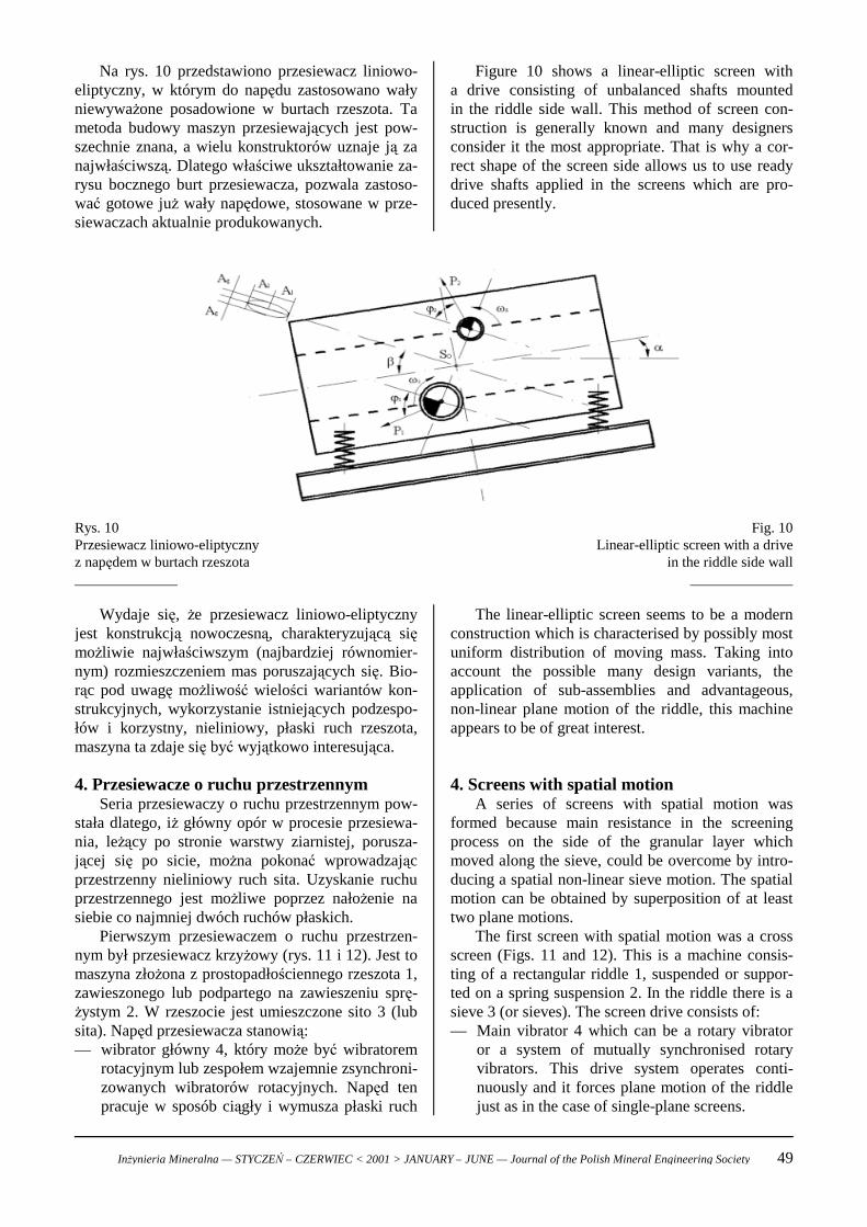
Figure 10 shows a linear-elliptic screen witha drive consisting of unbalanced shafts mountedin the riddle side wall. This method of screen con-struction is generally known and many designersconsider it the most appropriate. That is why a cor-rect shape of the screen side allows us to use readydrive shafts applied in the screens which are pro-duced presently.
Na rys. 10 przedstawiono przesiewacz liniowo-eliptyczny, w którym do napędu zastosowano wałyniewyważone posadowione w burtach rzeszota. Tametoda budowy maszyn przesiewających jest pow-szechnie znana, a wielu konstruktorów uznaje ją zanajwłaściwszą. Dlatego właściwe ukształtowanie za-rysu bocznego burt przesiewacza, pozwala zastoso-wać gotowe już wały napędowe, stosowane w prze-siewaczach aktualnie produkowanych.
Fig. 10Linear-elliptic screen with a drive
in the riddle side wall______________
Rys. 10Przesiewacz liniowo-eliptycznyz napędem w burtach rzeszota______________
The linear-elliptic screen seems to be a modernconstruction which is characterised by possibly mostuniform distribution of moving mass. Taking intoaccount the possible many design variants, theapplication of sub-assemblies and advantageous,non-linear plane motion of the riddle, this machineappears to be of great interest.
4. Screens with spatial motionA series of screens with spatial motion was
formed because main resistance in the screeningprocess on the side of the granular layer whichmoved along the sieve, could be overcome by intro-ducing a spatial non-linear sieve motion. The spatialmotion can be obtained by superposition of at leasttwo plane motions.
The first screen with spatial motion was a crossscreen (Figs. 11 and 12). This is a machine consis-ting of a rectangular riddle 1, suspended or suppor-ted on a spring suspension 2. In the riddle there is asieve 3 (or sieves). The screen drive consists of:— Main vibrator 4 which can be a rotary vibrator
or a system of mutually synchronised rotaryvibrators. This drive system operates conti-nuously and it forces plane motion of the riddlejust as in the case of single-plane screens.
Wydaje się, że przesiewacz liniowo-eliptycznyjest konstrukcją nowoczesną, charakteryzującą sięmożliwie najwłaściwszym (najbardziej równomier-nym) rozmieszczeniem mas poruszających się. Bio-rąc pod uwagę możliwość wielości wariantów kon-strukcyjnych, wykorzystanie istniejących podzespo-łów i korzystny, nieliniowy, płaski ruch rzeszota,maszyna ta zdaje się być wyjątkowo interesująca.
4. Przesiewacze o ruchu przestrzennymSeria przesiewaczy o ruchu przestrzennym pow-
stała dlatego, iż główny opór w procesie przesiewa-nia, leżący po stronie warstwy ziarnistej, porusza-jącej się po sicie, można pokonać wprowadzającprzestrzenny nieliniowy ruch sita. Uzyskanie ruchuprzestrzennego jest możliwe poprzez nałożenie nasiebie co najmniej dwóch ruchów płaskich.
Pierwszym przesiewaczem o ruchu przestrzen-nym był przesiewacz krzyżowy (rys. 11 i 12). Jest tomaszyna złożona z prostopadłościennego rzeszota 1,zawieszonego lub podpartego na zawieszeniu sprę-żystym 2. W rzeszocie jest umieszczone sito 3 (lubsita). Napęd przesiewacza stanowią:— wibrator główny 4, który może być wibratorem
rotacyjnym lub zespołem wzajemnie zsynchroni-zowanych wibratorów rotacyjnych. Napęd tenpracuje w sposób ciągły i wymusza płaski ruch
Inżynieria Mineralna — STYCZEŃ – CZERWIEC < 2001 > JANUARY – JUNE — Journal of the Polish Mineral Engineering Society 49
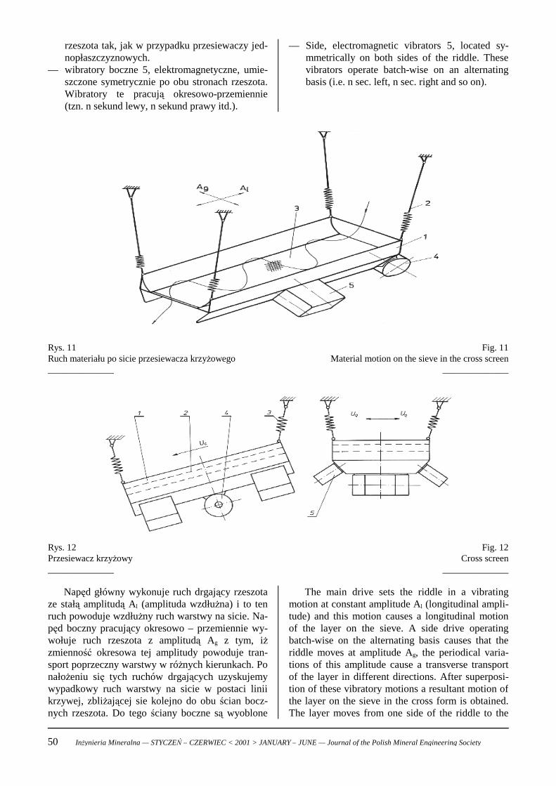
— Side, electromagnetic vibrators 5, located sy-mmetrically on both sides of the riddle. Thesevibrators operate batch-wise on an alternatingbasis (i.e. n sec. left, n sec. right and so on).
rzeszota tak, jak w przypadku przesiewaczy jed-nopłaszczyznowych.
— wibratory boczne 5, elektromagnetyczne, umie-szczone symetrycznie po obu stronach rzeszota.Wibratory te pracują okresowo-przemiennie(tzn. n sekund lewy, n sekund prawy itd.).
Fig. 11Material motion on the sieve in the cross screen
______________
Rys. 11Ruch materiału po sicie przesiewacza krzyżowego______________
Fig. 12Cross screen
______________
Rys. 12Przesiewacz krzyżowy______________
The main drive sets the riddle in a vibratingmotion at constant amplitude Al (longitudinal ampli-tude) and this motion causes a longitudinal motionof the layer on the sieve. A side drive operatingbatch-wise on the alternating basis causes that theriddle moves at amplitude Ag, the periodical varia-tions of this amplitude cause a transverse transportof the layer in different directions. After superposi-tion of these vibratory motions a resultant motion ofthe layer on the sieve in the cross form is obtained.The layer moves from one side of the riddle to the
Napęd główny wykonuje ruch drgający rzeszotaze stałą amplitudą Al (amplituda wzdłużna) i to tenruch powoduje wzdłużny ruch warstwy na sicie. Na-pęd boczny pracujący okresowo – przemiennie wy-wołuje ruch rzeszota z amplitudą Ag z tym, iżzmienność okresowa tej amplitudy powoduje tran-sport poprzeczny warstwy w różnych kierunkach. Ponałożeniu się tych ruchów drgających uzyskujemywypadkowy ruch warstwy na sicie w postaci liniikrzywej, zbliżającej sie kolejno do obu ścian bocz-nych rzeszota. Do tego ściany boczne są wyoblone
50 Inżynieria Mineralna — STYCZEŃ – CZERWIEC < 2001 > JANUARY – JUNE — Journal of the Polish Mineral Engineering Society
opposite one. Additionally, the side walls are roun-ded (Fig. 11) which causes additional pouring of thelayer. The way of material motion along the sieve iselongated, being longer than the sieve length.
The transport of the layer on the sieve is charac-terised by velocity ul, and the transverse motion isdetermined by variable velocity ug (Fig. 12). As aresult of superposition of velocity ul and ug theresultant motion is obtained. A characteristic featureof this screen is the lack of synchronisation betweenthe main and side drives.
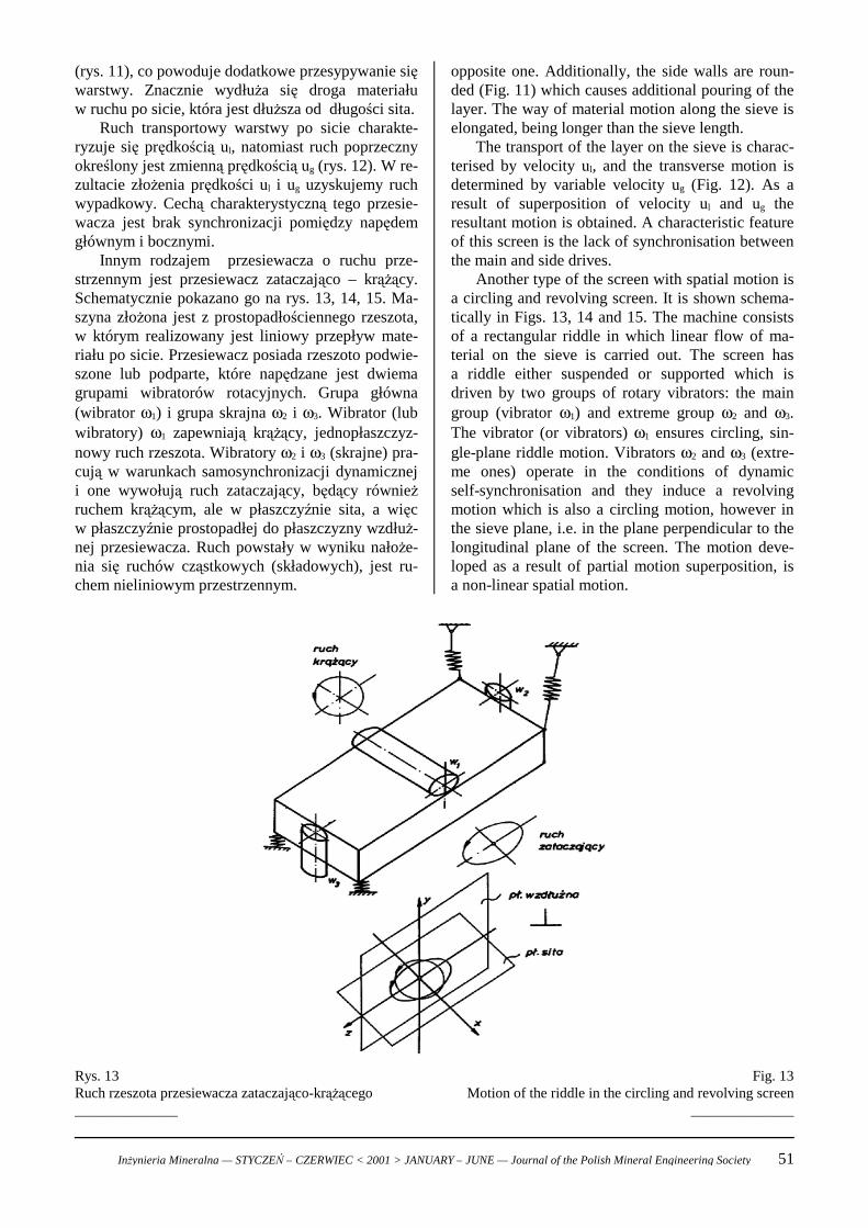
Another type of the screen with spatial motion isa circling and revolving screen. It is shown schema-tically in Figs. 13, 14 and 15. The machine consistsof a rectangular riddle in which linear flow of ma-terial on the sieve is carried out. The screen hasa riddle either suspended or supported which isdriven by two groups of rotary vibrators: the maingroup (vibrator ω1) and extreme group ω2 and ω3.The vibrator (or vibrators) ω1 ensures circling, sin-gle-plane riddle motion. Vibrators ω2 and ω3 (extre-me ones) operate in the conditions of dynamicself-synchronisation and they induce a revolvingmotion which is also a circling motion, however inthe sieve plane, i.e. in the plane perpendicular to thelongitudinal plane of the screen. The motion deve-loped as a result of partial motion superposition, isa non-linear spatial motion.
(rys. 11), co powoduje dodatkowe przesypywanie sięwarstwy. Znacznie wydłuża się droga materiałuw ruchu po sicie, która jest dłuższa od długości sita.
Ruch transportowy warstwy po sicie charakte-ryzuje się prędkością ul, natomiast ruch poprzecznyokreślony jest zmienną prędkością ug (rys. 12). W re-zultacie złożenia prędkości ul i ug uzyskujemy ruchwypadkowy. Cechą charakterystyczną tego przesie-wacza jest brak synchronizacji pomiędzy napędemgłównym i bocznymi.
Innym rodzajem przesiewacza o ruchu prze-strzennym jest przesiewacz zataczająco – krążący.Schematycznie pokazano go na rys. 13, 14, 15. Ma-szyna złożona jest z prostopadłościennego rzeszota,w którym realizowany jest liniowy przepływ mate-riału po sicie. Przesiewacz posiada rzeszoto podwie-szone lub podparte, które napędzane jest dwiemagrupami wibratorów rotacyjnych. Grupa główna(wibrator ω1) i grupa skrajna ω2 i ω3. Wibrator (lubwibratory) ω1 zapewniają krążący, jednopłaszczyz-nowy ruch rzeszota. Wibratory ω2 i ω3 (skrajne) pra-cują w warunkach samosynchronizacji dynamiczneji one wywołują ruch zataczający, będący równieżruchem krążącym, ale w płaszczyźnie sita, a więcw płaszczyźnie prostopadłej do płaszczyzny wzdłuż-nej przesiewacza. Ruch powstały w wyniku nałoże-nia się ruchów cząstkowych (składowych), jest ru-chem nieliniowym przestrzennym.
Fig. 13Motion of the riddle in the circling and revolving screen
______________
Rys. 13Ruch rzeszota przesiewacza zataczająco-krążącego______________
Inżynieria Mineralna — STYCZEŃ – CZERWIEC < 2001 > JANUARY – JUNE — Journal of the Polish Mineral Engineering Society 51
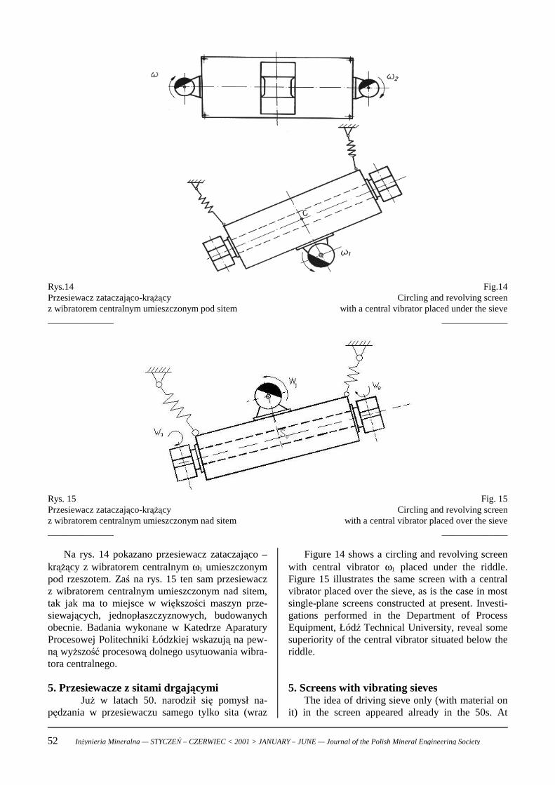
Fig.14Circling and revolving screen
with a central vibrator placed under the sieve______________
Rys.14Przesiewacz zataczająco-krążącyz wibratorem centralnym umieszczonym pod sitem______________
Fig. 15Circling and revolving screen
with a central vibrator placed over the sieve______________
Rys. 15Przesiewacz zataczająco-krążącyz wibratorem centralnym umieszczonym nad sitem______________
Figure 14 shows a circling and revolving screenwith central vibrator ω1 placed under the riddle.Figure 15 illustrates the same screen with a centralvibrator placed over the sieve, as is the case in mostsingle-plane screens constructed at present. Investi-gations performed in the Department of ProcessEquipment, Łódź Technical University, reveal somesuperiority of the central vibrator situated below theriddle.
5. Screens with vibrating sievesThe idea of driving sieve only (with material on
it) in the screen appeared already in the 50s. At
Na rys. 14 pokazano przesiewacz zataczająco –krążący z wibratorem centralnym ω1 umieszczonympod rzeszotem. Zaś na rys. 15 ten sam przesiewaczz wibratorem centralnym umieszczonym nad sitem,tak jak ma to miejsce w większości maszyn prze-siewających, jednopłaszczyznowych, budowanychobecnie. Badania wykonane w Katedrze AparaturyProcesowej Politechniki Łódzkiej wskazują na pew-ną wyższość procesową dolnego usytuowania wibra-tora centralnego.
5. Przesiewacze z sitami drgającymiJuż w latach 50. narodził się pomysł na-
pędzania w przesiewaczu samego tylko sita (wraz
52 Inżynieria Mineralna — STYCZEŃ – CZERWIEC < 2001 > JANUARY – JUNE — Journal of the Polish Mineral Engineering Society
present there are a few companies which producescreens with vibrating sieves (Stösselschwingsieb-maschinen, Schallsiebmaschinen). A characteristicfeature of these screens is a single-sided sieve drive.This means that the net is tossed by slats fromunderneath and this motion makes the material movealong the sieve thus causing its screening.
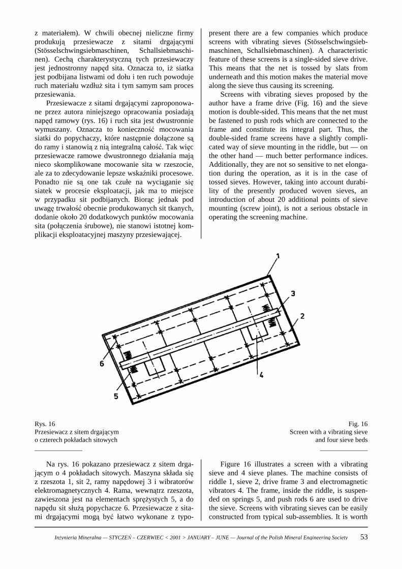
Screens with vibrating sieves proposed by theauthor have a frame drive (Fig. 16) and the sievemotion is double-sided. This means that the net mustbe fastened to push rods which are connected to theframe and constitute its integral part. Thus, thedouble-sided frame screens have a slightly compli-cated way of sieve mounting in the riddle, but — onthe other hand — much better performance indices.Additionally, they are not so sensitive to net elonga-tion during the operation, as it is in the case oftossed sieves. However, taking into account durabi-lity of the presently produced woven sieves, anintroduction of about 20 additional points of sievemounting (screw joint), is not a serious obstacle inoperating the screening machine.
z materiałem). W chwili obecnej nieliczne firmyprodukują przesiewacze z sitami drgającymi(Stösselschwingsiebmaschinen, Schallsiebmaschi-nen). Cechą charakterystyczną tych przesiewaczyjest jednostronny napęd sita. Oznacza to, iż siatkajest podbijana listwami od dołu i ten ruch powodujeruch materiału wzdłuż sita i tym samym sam procesprzesiewania.
Przesiewacze z sitami drgającymi zaproponowa-ne przez autora niniejszego opracowania posiadająnapęd ramowy (rys. 16) i ruch sita jest dwustronniewymuszany. Oznacza to konieczność mocowaniasiatki do popychaczy, które następnie dołączone sądo ramy i stanowią z nią integralną całość. Tak więcprzesiewacze ramowe dwustronnego działania mająnieco skomplikowane mocowanie sita w rzeszocie,ale za to zdecydowanie lepsze wskaźniki procesowe.Ponadto nie są one tak czułe na wyciąganie sięsiatek w procesie eksploatacji, jak ma to miejscew przypadku sit podbijanych. Biorąc jednak poduwagę trwałość obecnie produkowanych sit tkanych,dodanie około 20 dodatkowych punktów mocowaniasita (połączenia śrubowe), nie stanowi istotnej kom-plikacji eksploatacyjnej maszyny przesiewającej.
Fig. 16Screen with a vibrating sieve
and four sieve beds______________
Rys. 16Przesiewacz z sitem drgającymo czterech pokładach sitowych______________
Figure 16 illustrates a screen with a vibratingsieve and 4 sieve planes. The machine consists ofriddle 1, sieve 2, drive frame 3 and electromagneticvibrators 4. The frame, inside the riddle, is suspen-ded on springs 5, and push rods 6 are used to drivethe sieve. Screens with vibrating sieves can be easilyconstructed from typical sub-assemblies. It is worth
Na rys. 16 pokazano przesiewacz z sitem drga-jącym o 4 pokładach sitowych. Maszyna składa sięz rzeszota 1, sit 2, ramy napędowej 3 i wibratorówelektromagnetycznych 4. Rama, wewnątrz rzeszota,zawieszona jest na elementach sprężystych 5, a donapędu sit służą popychacze 6. Przesiewacze z sita-mi drgającymi mogą być łatwo wykonane z typo-
Inżynieria Mineralna — STYCZEŃ – CZERWIEC < 2001 > JANUARY – JUNE — Journal of the Polish Mineral Engineering Society 53
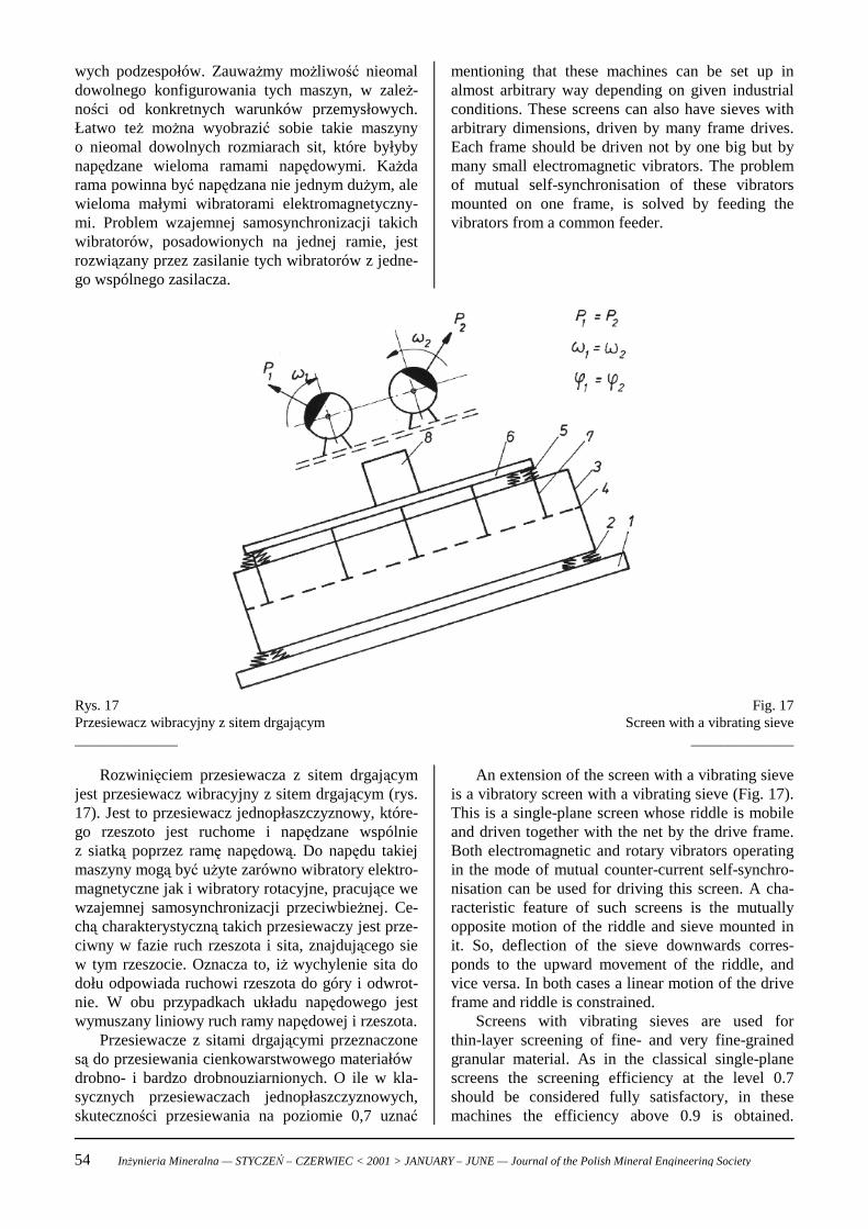
mentioning that these machines can be set up inalmost arbitrary way depending on given industrialconditions. These screens can also have sieves witharbitrary dimensions, driven by many frame drives.Each frame should be driven not by one big but bymany small electromagnetic vibrators. The problemof mutual self-synchronisation of these vibratorsmounted on one frame, is solved by feeding thevibrators from a common feeder.
wych podzespołów. Zauważmy możliwość nieomaldowolnego konfigurowania tych maszyn, w zależ-ności od konkretnych warunków przemysłowych.Łatwo też można wyobrazić sobie takie maszynyo nieomal dowolnych rozmiarach sit, które byłybynapędzane wieloma ramami napędowymi. Każdarama powinna być napędzana nie jednym dużym, alewieloma małymi wibratorami elektromagnetyczny-mi. Problem wzajemnej samosynchronizacji takichwibratorów, posadowionych na jednej ramie, jestrozwiązany przez zasilanie tych wibratorów z jedne-go wspólnego zasilacza.
Fig. 17Screen with a vibrating sieve
______________
Rys. 17Przesiewacz wibracyjny z sitem drgającym______________
An extension of the screen with a vibrating sieveis a vibratory screen with a vibrating sieve (Fig. 17).This is a single-plane screen whose riddle is mobileand driven together with the net by the drive frame.Both electromagnetic and rotary vibrators operatingin the mode of mutual counter-current self-synchro-nisation can be used for driving this screen. A cha-racteristic feature of such screens is the mutuallyopposite motion of the riddle and sieve mounted init. So, deflection of the sieve downwards corres-ponds to the upward movement of the riddle, andvice versa. In both cases a linear motion of the driveframe and riddle is constrained.
Screens with vibrating sieves are used forthin-layer screening of fine- and very fine-grainedgranular material. As in the classical single-planescreens the screening efficiency at the level 0.7should be considered fully satisfactory, in thesemachines the efficiency above 0.9 is obtained.
Rozwinięciem przesiewacza z sitem drgającymjest przesiewacz wibracyjny z sitem drgającym (rys.17). Jest to przesiewacz jednopłaszczyznowy, które-go rzeszoto jest ruchome i napędzane wspólniez siatką poprzez ramę napędową. Do napędu takiejmaszyny mogą być użyte zarówno wibratory elektro-magnetyczne jak i wibratory rotacyjne, pracujące wewzajemnej samosynchronizacji przeciwbieżnej. Ce-chą charakterystyczną takich przesiewaczy jest prze-ciwny w fazie ruch rzeszota i sita, znajdującego siew tym rzeszocie. Oznacza to, iż wychylenie sita dodołu odpowiada ruchowi rzeszota do góry i odwrot-nie. W obu przypadkach układu napędowego jestwymuszany liniowy ruch ramy napędowej i rzeszota.
Przesiewacze z sitami drgającymi przeznaczonesą do przesiewania cienkowarstwowego materiałów drobno- i bardzo drobnouziarnionych. O ile w kla-sycznych przesiewaczach jednopłaszczyznowych,skuteczności przesiewania na poziomie 0,7 uznać
54 Inżynieria Mineralna — STYCZEŃ – CZERWIEC < 2001 > JANUARY – JUNE — Journal of the Polish Mineral Engineering Society
Screens with vibrating sieves are inclined at a biggerangle than in the case of other machines. This angleis usually bigger than 25° and does not exceed 45°.The dynamic factor of such a screen, calculated inthe mounting point, is usually higher than insingle-plane screens reaching < 15.
6. Rotary screensThese screens were developed with the intention
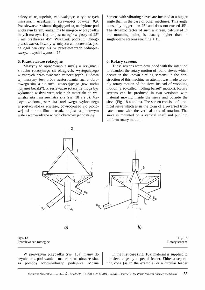
to abandon the rotary motion of round sieves whichoccurs in the known circling screens. In the con-struction of this machine an attempt was made to ap-ply rotary motion of the sieve instead of wobblingmotion (a so-called “rolling barrel” motion). Rotaryscreens can be produced in two versions: withmaterial moving inside the sieve and outside thesieve (Fig. 18 a and b). The screen consists of a co-nical sieve which is in the form of a reversed trun-cated cone with the vertical axis of rotation. Thesieve is mounted on a vertical shaft and put intouniform rotary motion.
należy za najzupełniej zadowalające, o tyle w tychmaszynach uzyskujemy sprawności powyżej 0,9.Przesiewacze z sitami drgającymi są nachylone podwiększym kątem, aniżeli ma to miejsce w przypadkuinnych maszyn. Kąt ten jest na ogół większy od 25°i nie przekracza 45°. Wskaźnik podrzutu takiegoprzesiewacza, liczony w miejscu zamocowania, jestna ogół większy niż w przesiewaczach jednopła-szczyznowych i wynosi <15.
6. Przesiewacze rotacyjneMaszyny te opracowano z myślą o rezygnacji
z ruchu rotacyjnego sit okrągłych, występującegow znanych przesiewaczach zataczających. Budowatej maszyny jest próbą zastosowania ruchu obro-towego sita, a nie ruchu zataczającego (tzw. ruchu„pijanej beczki”). Przesiewacze rotacyjne mogą byćwykonane w dwu wersjach: ruch materiału do we-wnątrz sita i na zewnątrz sita (rys. 18 a i b). Ma-szyna złożona jest z sita stożkowego, wykonanegow postaci stożka ściętego, odwróconego i o piono-wej osi obrotu. Sito to osadzone jest na pionowymwale i wprowadzane w ruch obrotowy jednostajny.
Fig. 18Rotary screens
______________
Rys. 18Przesiewacze rotacyjne______________
In the first case (Fig. 18a) material is supplied tothe sieve edge by a special feeder. Either a separa-ting cone (as in the example) or a circular feeder
W pierwszym przypadku (rys. 18a) mamy doczynienia z podawaniem materiału na obrzeże sita,za pomocą odpowiedniego podajnika. Można
Inżynieria Mineralna — STYCZEŃ – CZERWIEC < 2001 > JANUARY – JUNE — Journal of the Polish Mineral Engineering Society 55
1 2
a) b)
can be used. The sieve rotates slowly, but forces thatact on it (the forces of friction and gravity) causea spiral motion of the material to the sieve centre. Inthis time the feed is screened. The system of co-llecting the grain fractions is clearly illustrated in thefigure.
In the second case (Fig. 18b) we have a high-speed sieve (ω1<<ω2) and then the feed is suppliedonto the centre of the conical sieve. Under theinfluence of centrifugal force which is much higherthan other forces acting on the grain, i.e. the forcesof friction and gravity, the feed moves spirally to-wards the sieve edge. In this time the granular ma-terial is screened. Collection of the screened productsimilar as in the first case is shown in a schematic.
The described screens are designated for thin-layer screening of easily screened granular materials.
7. Feed supply to the screensIn many cases of industrial applications of
screening machines a mistake is made in feedingmaterial to the screens. Of special importance arethe following two conditions:1) Feeding of the material from the smallest possi-
ble height onto the sieve — eliminates impact ofthe layer against a usually thin sieve
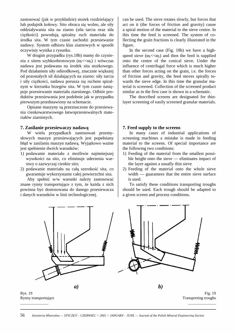
2) Feeding of the material onto the whole sievewidth — guarantees that the entire sieve surfaceis used.To satisfy these conditions transporting troughs
should be used. Each trough should be adapted toa given screen and process conditions.
zastosować (jak w przykładzie) stożek rozdzielającylub podajnik kołowy. Sito obraca się wolno, ale siłyoddziaływania sita na ziarno (siła tarcia oraz siłaciężkości) powodują spiralny ruch materiału dośrodka sita. W tym czasie zachodzi przesiewanienadawy. System odbioru klas ziarnowych w sposóboczywisty wynika z rysunku.
W drugim przypadku (rys.18b) mamy do czynie-nia z sitem szybkoobrotowym (ω1<<ω2) i wówczasnadawa jest podawana na środek sita stożkowego.Pod działaniem siły odśrodkowej, znacznie większejod pozostałych sił działających na ziarno: siły tarciai siły ciężkości, nadawa porusza się ruchem spiral-nym w kierunku brzegów sita. W tym czasie nastę-puje przesiewanie materiału ziarnistego. Odbiór pro-duktów przesiewania jest podobnie jak w przypadkupierwszym przedstawiony na schemacie.
Opisane maszyny są przeznaczone do przesiewa-nia cienkowarstwowego łatwoprzesiewalnych mate-riałów ziarnistych.
7. Zasilanie przesiewaczy nadawąW wielu przypadkach zastosowań przemy-
słowych maszyn przesiewających jest popełnianybłąd w zasilaniu maszyn nadawą. Wyjątkowo ważnejest spełnienie dwóch warunków:1) podawanie materiału z możliwie najmniejszej
wysokości na sito, co eliminuje uderzenia war-stwy o zazwyczaj cienkie sito;
2) podawanie materiału na całą szerokość sita, cogwarantuje wykorzystanie całej powierzchni sita.Aby spełnić w/w warunki należy zastosować
znane rynny transportujące z tym, że każda z nichpowinna być dostosowana do danego przesiewaczai danych warunków w linii technologicznej.
Fig. 19Transporting troughs
______________
Rys. 19Rynny transportujące______________
56 Inżynieria Mineralna — STYCZEŃ – CZERWIEC < 2001 > JANUARY – JUNE — Journal of the Polish Mineral Engineering Society
a) b)
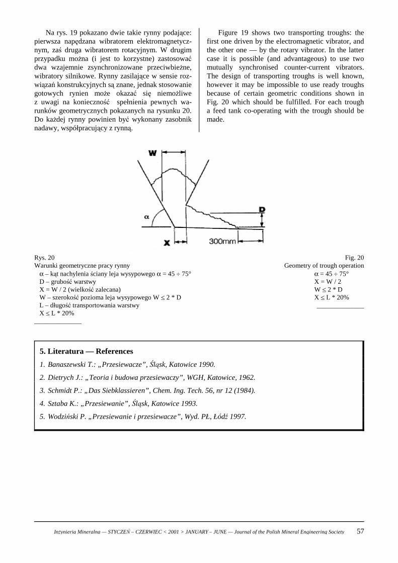
Figure 19 shows two transporting troughs: thefirst one driven by the electromagnetic vibrator, andthe other one — by the rotary vibrator. In the lattercase it is possible (and advantageous) to use twomutually synchronised counter-current vibrators.The design of transporting troughs is well known,however it may be impossible to use ready troughsbecause of certain geometric conditions shown inFig. 20 which should be fulfilled. For each trougha feed tank co-operating with the trough should bemade.
Na rys. 19 pokazano dwie takie rynny podające:pierwsza napędzana wibratorem elektromagnetycz-nym, zaś druga wibratorem rotacyjnym. W drugimprzypadku można (i jest to korzystne) zastosowaćdwa wzajemnie zsynchronizowane przeciwbieżne,wibratory silnikowe. Rynny zasilające w sensie roz-wiązań konstrukcyjnych są znane, jednak stosowaniegotowych rynien może okazać się niemożliwez uwagi na konieczność spełnienia pewnych wa-runków geometrycznych pokazanych na rysunku 20.Do każdej rynny powinien być wykonany zasobniknadawy, współpracujący z rynną.
Fig. 20Geometry of trough operation
α = 45 + 75°X = W / 2 W [ 2 * DX [ L * 20%______________
Rys. 20Warunki geometryczne pracy rynny
α – kąt nachylenia ściany leja wysypowego α = 45 + 75°D – grubość warstwyX = W / 2 (wielkość zalecana)W – szerokość pozioma leja wysypowego W [ 2 * DL – długość transportowania warstwyX [ L * 20%
______________
5. Literatura — References
1. Banaszewski T.: „Przesiewacze”, Śląsk, Katowice 1990.
2. Dietrych J.: „Teoria i budowa przesiewaczy”, WGH, Katowice, 1962.
3. Schmidt P.: „Das Siebklassieren”, Chem. Ing. Tech. 56, nr 12 (1984).
4. Sztaba K.: „Przesiewanie”, Śląsk, Katowice 1993.
5. Wodziński P. „Przesiewanie i przesiewacze”, Wyd. PŁ, Łódź 1997.
Inżynieria Mineralna — STYCZEŃ – CZERWIEC < 2001 > JANUARY – JUNE — Journal of the Polish Mineral Engineering Society 57