Embed Size (px)
Citation preview

ARMADIO REFRIGERATO REFRIGERATED CABINET
PROFESSIONALROLL-IN / THROUGH
PASTRY - ICE
Manuale d’uso e manutenzioneUse and maintenance manual
Rev.7-6
1
ITALIANO
Grazie per aver scelto questo prodotto.
Leggere attentamente le avvertenze contenute nel presente manuale in quanto forniscono importanti indicazioni riguardanti la sicurezza, d’uso e di manutenzione.Conservare con cura questo manuale per ogni ulteriore consultazione dei vari operatori.
In alcune parti del manuale è presente il simbolo indicante una avvertenza importante da rispettare ai fini della sicurezza.
CAPITOLO 1 CARATTERISTICHE LIMITE DI FUNZIONAMENTO
L’armadio frigorifero è stato progettato e realizzato per poter funzionare in condizioni ottimali in ambienti con temperature fino a +10°C e i +43°C (+10°C e i +32°C modelli con porta a vetri), con adeguato ricircolo d’aria. In luoghi con caratteristiche diverse da quelle previste non sarà possibile garantire le prestazioni dichiarate. La tensione di alimentazione deve essere 230V +/- 10% 50Hz di serie, oppure quella indicata sull’etichetta CE
L’armadio frigorifero è utilizzabile esclusivamente entro i limiti di temperatura previsti dal costruttore, per identificare il corretto range di funzionamento leggere le lettere successive all’ultima cifra del modello riportato sulla targhetta CE e confrontarla con la tabella di seguito riportata:
Serie TemperaturaTNV +2° +10°CTNBV -2° +10°CBTV -10° -22°C / 10° -25°C (PASTRY ICE)BTST -12° -25°CTNS PE -5° +5°C
L’armadio frigorifero è conforme alle direttive Europee come riportato in dettaglio nell’allegato “Dichiarazione CE di conformità”
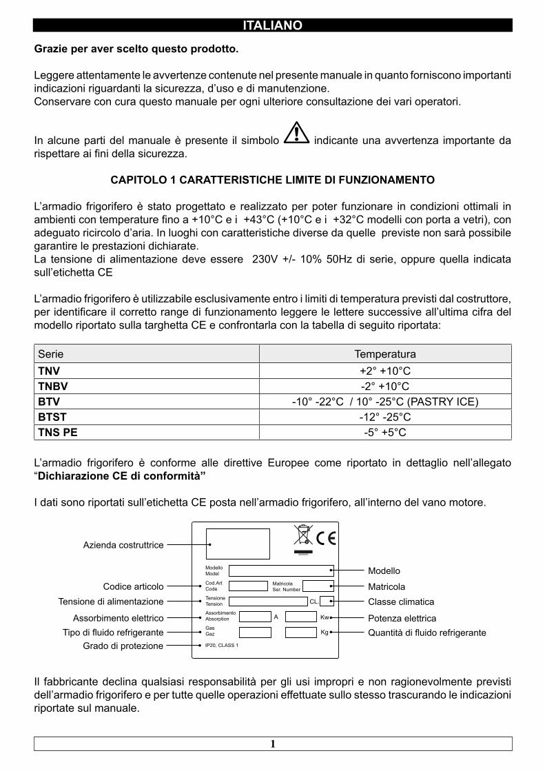
I dati sono riportati sull’etichetta CE posta nell’armadio frigorifero, all’interno del vano motore.
A Kw
Kg
CL.
MatricolaSer. Number
ModelloModel
Cod.ArtCode
TensioneTension
AssorbimentoAbsorption
GasGaz
IP20, CLASS 1
Modello
MatricolaClasse climatica
Potenza elettricaQuantità di fluido refrigerante
Azienda costruttrice
Codice articoloTensione di alimentazione
Assorbimento elettricoTipo di fluido refrigerante
Grado di protezione
Il fabbricante declina qualsiasi responsabilità per gli usi impropri e non ragionevolmente previsti dell’armadio frigorifero e per tutte quelle operazioni effettuate sullo stesso trascurando le indicazioni riportate sul manuale.
2
ITALIANO
Di seguito sono elencate le principali norme di sicurezza generali:
- Non utilizzare o inserire apparecchi elettrici all’interno dei comparti refrigerati se non del tipo consigliato dal produttore- Non toccare l’armadio frigorifero avendo mani o piedi umidi o bagnati- Non usare l’armadio frigorifero a piedi nudi- Non inserire cacciaviti od altro tra le protezioni o le parti in movimento- Non tirare il cavo di alimentazione per scollegare l’armadio frigorifero dalla rete di alimentazione elettrica- L’armadio frigorifero non è adatto all’uso da parte di persone (compresi i bambini) con problemi fisici, mentali o con mancanza di esperienza e conoscenza a meno che esse non siano controllate o istruite all’uso dell’apparecchio da una persona responsabile per la loro sicurezza. I bambini devono essere sorvegliati per assicurarsi che non giochino con l’apparecchio.- Prima di effettuare qualsiasi operazione di pulizia o manutenzione disinserire l’armadio frigorifero dalla rete di alimentazione elettrica spegnendo l’interruttore generale e staccando la spina- In caso di guasto e/o di cattivo funzionamento dell’armadio frigorifero, spegnerlo ed astenersi da qualsiasi tentativo di riparazione o di intervento diretto. E’ necessario rivolgersi esclusivamente a personale qualificato.
L’armadio frigorifero è costituito da una monoscocca modulare rivestita con materiali diversi e isolata con poliuretano espanso a densità 42 kg/m3.
In fase di progettazione e realizzazione sono stati adottati tutti gli accorgimenti per ottenere un armadio frigorifero conforme ai requisiti di sicurezza e igiene quali: gli angoli arrotondati interni, imbutiture con scarico all’esterno dei liquidi di condensa, assenza di superfici rugose, protezioni fisse su componenti mobili o pericolosi.
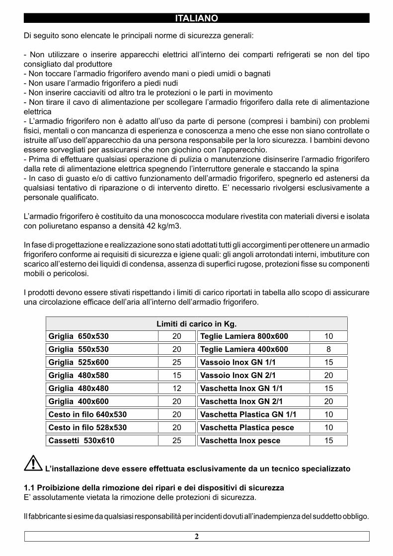
I prodotti devono essere stivati rispettando i limiti di carico riportati in tabella allo scopo di assicurare una circolazione efficace dell’aria all’interno dell’armadio frigorifero.
Limiti di carico in Kg.Griglia 650x530 20 Teglie Lamiera 800x600 10Griglia 550x530 20 Teglie Lamiera 400x600 8Griglia 525x600 25 Vassoio Inox GN 1/1 15Griglia 480x580 15 Vassoio Inox GN 2/1 20Griglia 480x480 12 Vaschetta Inox GN 1/1 15Griglia 400x600 20 Vaschetta Inox GN 2/1 20Cesto in filo 640x530 20 Vaschetta Plastica GN 1/1 10Cesto in filo 528x530 20 Vaschetta Plastica pesce 10Cassetti 530x610 25 Vaschetta Inox pesce 15
L’installazione deve essere effettuata esclusivamente da un tecnico specializzato
1.1 Proibizione della rimozione dei ripari e dei dispositivi di sicurezzaE’ assolutamente vietata la rimozione delle protezioni di sicurezza.
Il fabbricante si esime da qualsiasi responsabilità per incidenti dovuti all’inadempienza del suddetto obbligo.
3
ITALIANO
1.2 Indicazioni sulle operazioni di emergenza in caso di incendio- staccare l’armadio frigorifero dalla presa elettrica oppure interrompere l’alimentazione generale- non utilizzare getti d’acqua- usare estintori a polvere o CO2
CAPITOLO 2 PULIZIA DEL FRIGORIFERO
Poiché nell’armadio frigorifero vanno conservati dei prodotti alimentari è necessaria l’operazione di pulizia ai fini dell’igiene e della tutela della salute. La pulizia dell’armadio frigorifero è già stata effettuata in fabbrica. Si suggerisce tuttavia di effettuare un ulteriore lavaggio delle parti interne prima dell’uso, assicurandosi che il cavo di alimentazione sia scollegato.
2.1 Pulizia del mobile interno ed esternoAllo scopo vengono indicati
- i prodotti di pulizia: acqua e detergenti neutri non abrasivi. NON USARE SOLVENTI E DILUENTI- i metodi di pulizia: lavare le parti interne ed esterne con acqua tiepida e sapone neutro o con panno o spugna con prodotti idonei- la disinfezione: evitare sostanze che possano alterare le caratteristiche organolettiche degli alimenti- la risciacquatura: panno o spugna imbevuti d’acqua tiepida. NON USARE GETTI D’ACQUA- la frequenza: si consiglia settimanale, l’utilizzatore può’ stabilire frequenze diverse in funzione del tipo di alimenti conservati.
IMPORTANTE: Pulire frequentemente le guarnizioni delle porte. Alcuni prodotti conservati protrebbero rilasciare degli enzimi che attaccano la guarnizione deteriorandola molto velocemente. Per la pulizia utilizzare prodotti specifici disponibili a richiesta anche presso la nostra rete commerciale.
2.2 Pulizia del condensatoreL’efficienza dell’armadio frigorifero è compromessa dall’intasamento del condensatore per cui è necessario provvedere alla pulizia dello stesso con frequenza mensile. Prima di effettuare questa operazione spegnere l’armadio frigorifero, disinserire il cavo di alimentazione e procedere come segue:
Motore in basso - aprire il frontale portacomandi svitando le apposite viti e facendolo ruotare sulle cerniere poste in basso.
Motore in alto - per i modelli con frontale fisso non ribaltabile, salire su una scaletta sicura e accedere direttamente al condensatore posto sulla parte superiore l’armadio frigorifero.
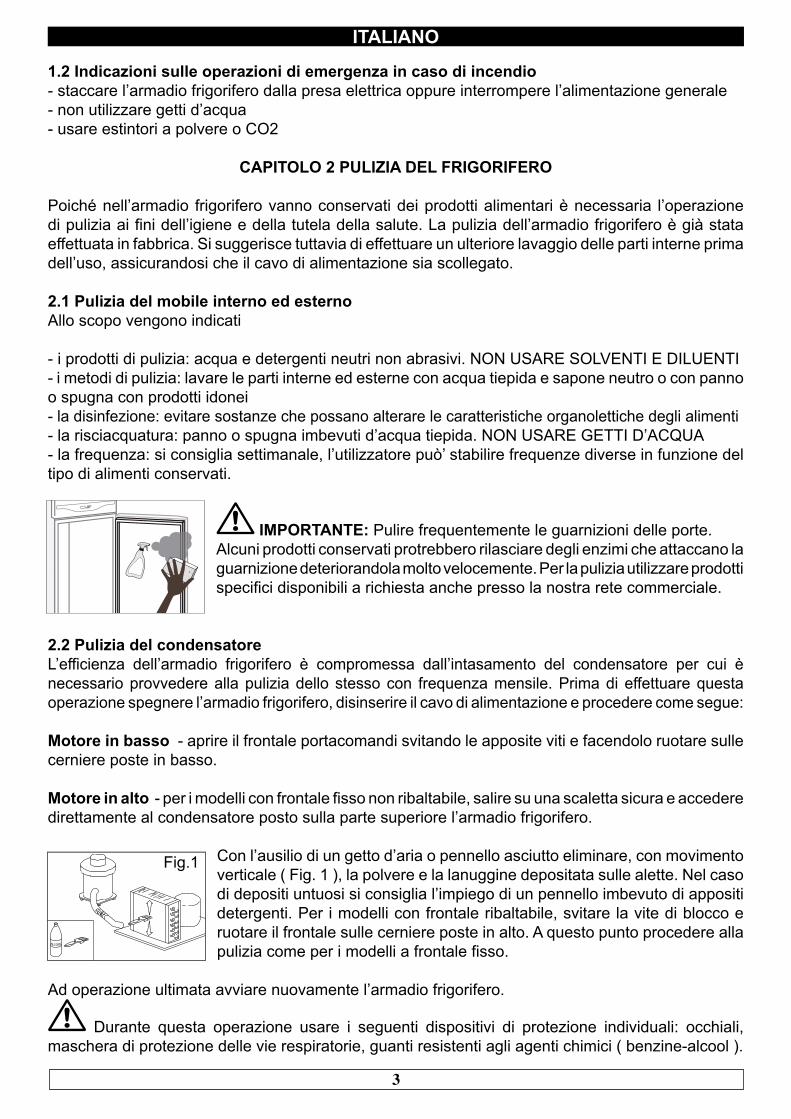
Con l’ausilio di un getto d’aria o pennello asciutto eliminare, con movimento verticale ( Fig. 1 ), la polvere e la lanuggine depositata sulle alette. Nel caso di depositi untuosi si consiglia l’impiego di un pennello imbevuto di appositi detergenti. Per i modelli con frontale ribaltabile, svitare la vite di blocco e ruotare il frontale sulle cerniere poste in alto. A questo punto procedere alla pulizia come per i modelli a frontale fisso.
Ad operazione ultimata avviare nuovamente l’armadio frigorifero.
Durante questa operazione usare i seguenti dispositivi di protezione individuali: occhiali, maschera di protezione delle vie respiratorie, guanti resistenti agli agenti chimici ( benzine-alcool ).
ALCOOL
Fig.1
4
ITALIANO
CAPITOLO 3 VERIFICHE PERIODICHE DA ESEGUIRE
Di seguito vengono elencati i punti o i gruppi dell’armadio frigorifero che necessitano di verifiche periodiche:- integrità ed efficienza delle guarnizioni delle porte- integrità delle griglie a contatto con gli alimenti- integrità delle cerniere di fissaggio delle porte- integrità del cavo di alimentazione
3.1 PRECAUZIONI IN CASO DI LUNGA INATTIVITA’Per lunga inattività si intende un periodo di fermo superiore a 15 giorni.E’ necessario procedere come segue:- spegnere l’armadio frigorifero e scollegarlo dall’alimentazione elettrica - effettuare la pulizia accurata del mobile interno, ripiani, vassoi, guide e supporti con particolare attenzione ai punti critici quali giunzioni e guarnizioni magnetiche, secondo le indicazioni riportate al capitolo 2.- lasciare le porte semiaperte per evitare il ristagno d’aria e umidità residua
CAPITOLO 4 MANUTENZIONE PREVENTIVA
4.1 Riavvio dopo lunga inattivitàIl riavvio dopo lunga inattività è un evento che richiede un intervento di manutenzione preventiva.E’ necessario eseguire una accurata pulizia come descritto nel capitolo 2.
4.2 Controllo dei dispositivi di avvertimento e comandoSi consiglia di richiedere al rivenditore un contratto di assistenza o manutenzione periodica che comprenda:- pulizia del condensatore- verifica della carica del fluido frigorigeno- verifica del funzionamento a ciclo completo- sicurezza elettrica
CAPITOLO 5 MANUTENZIONE STRAORDINARIA E RIPARAZIONE
Tutti gli interventi di manutenzione che non sono stati descritti nei capitoli precedenti sono da considerare “ Manutenzione Straordinaria “. La manutenzione straordinaria e la riparazione sono compiti riservati esclusivamente al personale specializzato ed autorizzato dal fabbricante.Si declina ogni responsabilità per interventi condotti dall’utilizzatore, da personale non autorizzato, o per l’utilizzo di ricambi non originali.
5
ITALIANO
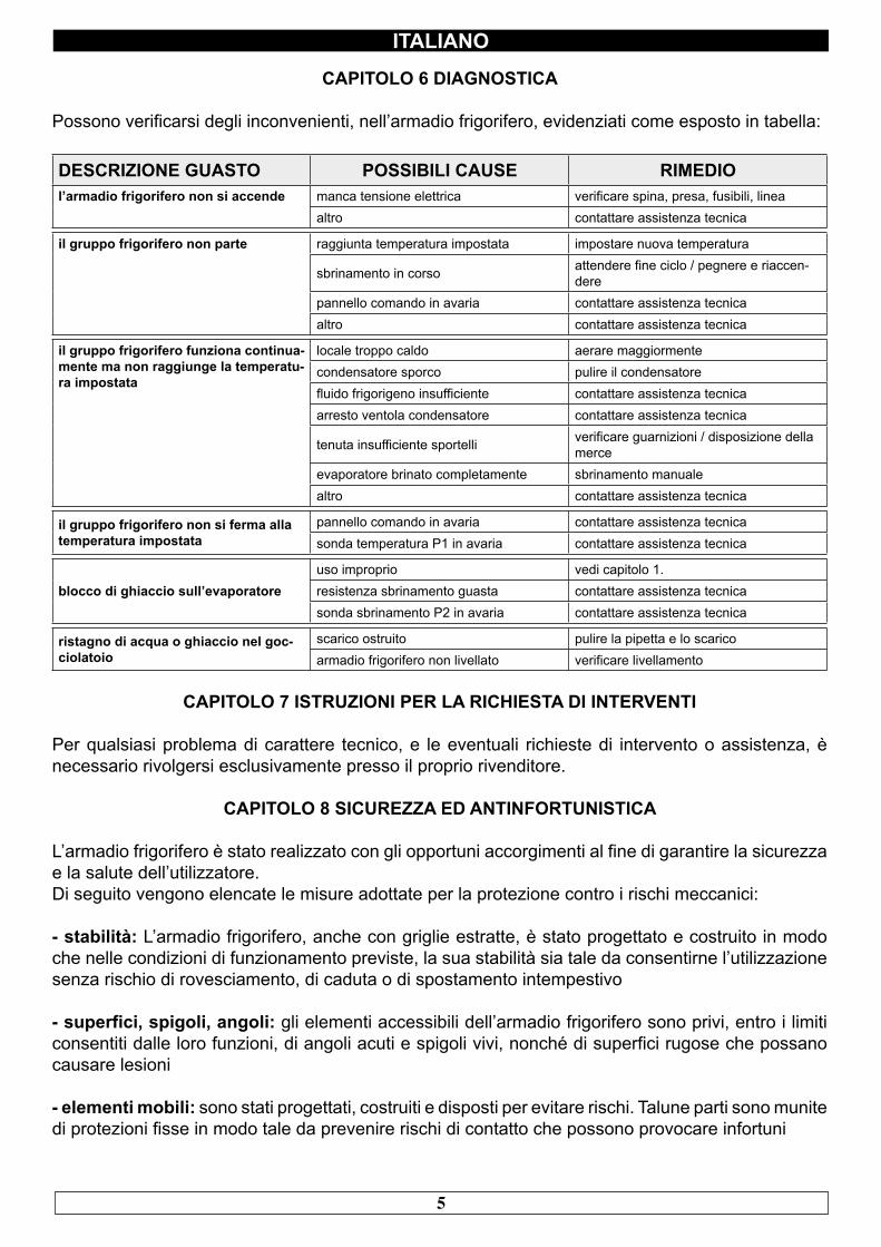
CAPITOLO 6 DIAGNOSTICA
Possono verificarsi degli inconvenienti, nell’armadio frigorifero, evidenziati come esposto in tabella:
DESCRIZIONE GUASTO POSSIBILI CAUSE RIMEDIOl’armadio frigorifero non si accende manca tensione elettrica verificare spina, presa, fusibili, linea
altro contattare assistenza tecnica
il gruppo frigorifero non parte raggiunta temperatura impostata impostare nuova temperatura
sbrinamento in corso attendere fine ciclo / pegnere e riaccen-dere
pannello comando in avaria contattare assistenza tecnicaaltro contattare assistenza tecnica
il gruppo frigorifero funziona continua-mente ma non raggiunge la temperatu-ra impostata
locale troppo caldo aerare maggiormentecondensatore sporco pulire il condensatorefluido frigorigeno insufficiente contattare assistenza tecnicaarresto ventola condensatore contattare assistenza tecnica
tenuta insufficiente sportelli verificare guarnizioni / disposizione della merce
evaporatore brinato completamente sbrinamento manualealtro contattare assistenza tecnica
il gruppo frigorifero non si ferma alla temperatura impostata
pannello comando in avaria contattare assistenza tecnicasonda temperatura P1 in avaria contattare assistenza tecnica
blocco di ghiaccio sull’evaporatoreuso improprio vedi capitolo 1.resistenza sbrinamento guasta contattare assistenza tecnicasonda sbrinamento P2 in avaria contattare assistenza tecnica
ristagno di acqua o ghiaccio nel goc-ciolatoio
scarico ostruito pulire la pipetta e lo scaricoarmadio frigorifero non livellato verificare livellamento
CAPITOLO 7 ISTRUZIONI PER LA RICHIESTA DI INTERVENTI
Per qualsiasi problema di carattere tecnico, e le eventuali richieste di intervento o assistenza, è necessario rivolgersi esclusivamente presso il proprio rivenditore.
CAPITOLO 8 SICUREZZA ED ANTINFORTUNISTICA
L’armadio frigorifero è stato realizzato con gli opportuni accorgimenti al fine di garantire la sicurezza e la salute dell’utilizzatore.Di seguito vengono elencate le misure adottate per la protezione contro i rischi meccanici:
- stabilità: L’armadio frigorifero, anche con griglie estratte, è stato progettato e costruito in modo che nelle condizioni di funzionamento previste, la sua stabilità sia tale da consentirne l’utilizzazione senza rischio di rovesciamento, di caduta o di spostamento intempestivo
- superfici, spigoli, angoli: gli elementi accessibili dell’armadio frigorifero sono privi, entro i limiti consentiti dalle loro funzioni, di angoli acuti e spigoli vivi, nonché di superfici rugose che possano causare lesioni
- elementi mobili: sono stati progettati, costruiti e disposti per evitare rischi. Talune parti sono munite di protezioni fisse in modo tale da prevenire rischi di contatto che possono provocare infortuni
6
ITALIANO
Di seguito vengono elencate le misure adottate per la protezione contro altri rischi:
- energia elettrica: L’armadio frigorifero è stato progettato, costruito ed equipaggiato in modo da prevenire i rischi elettrici, nel rispetto della normativa specifica vigente
- rumore: L’armadio frigorifero è stato progettato e costruito in modo tale che i rischi dovuti all’emissione di rumore aereo siano ridotti al livello minimo
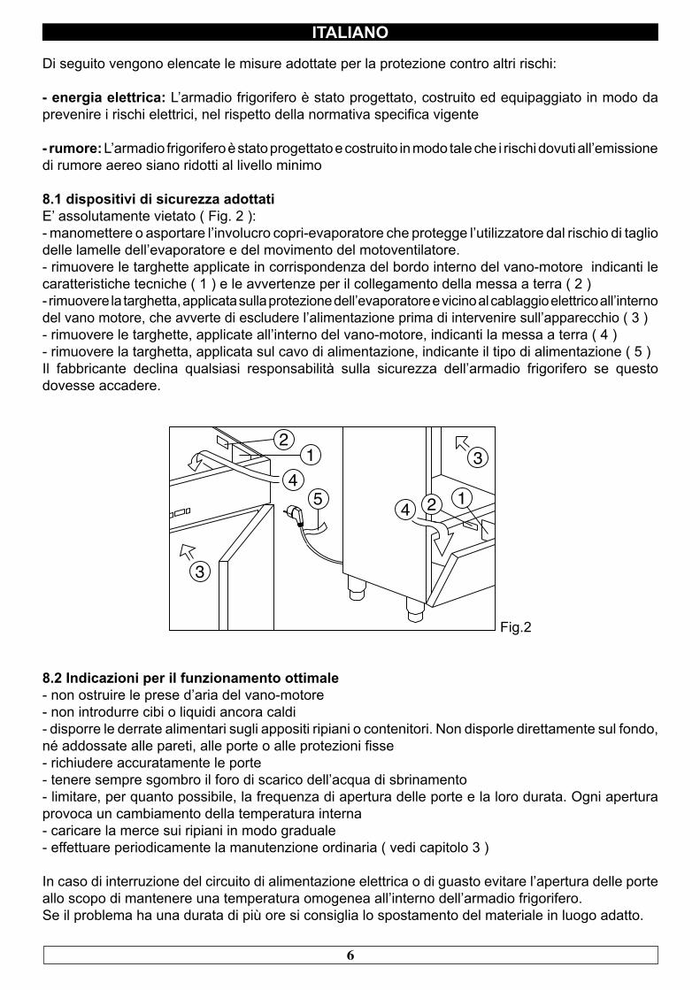
8.1 dispositivi di sicurezza adottatiE’ assolutamente vietato ( Fig. 2 ):- manomettere o asportare l’involucro copri-evaporatore che protegge l’utilizzatore dal rischio di taglio delle lamelle dell’evaporatore e del movimento del motoventilatore.- rimuovere le targhette applicate in corrispondenza del bordo interno del vano-motore indicanti le caratteristiche tecniche ( 1 ) e le avvertenze per il collegamento della messa a terra ( 2 )- rimuovere la targhetta, applicata sulla protezione dell’evaporatore e vicino al cablaggio elettrico all’interno del vano motore, che avverte di escludere l’alimentazione prima di intervenire sull’apparecchio ( 3 )- rimuovere le targhette, applicate all’interno del vano-motore, indicanti la messa a terra ( 4 )- rimuovere la targhetta, applicata sul cavo di alimentazione, indicante il tipo di alimentazione ( 5 )Il fabbricante declina qualsiasi responsabilità sulla sicurezza dell’armadio frigorifero se questo dovesse accadere.
12
3
34
5 4 2 1
Fig.2
8.2 Indicazioni per il funzionamento ottimale- non ostruire le prese d’aria del vano-motore- non introdurre cibi o liquidi ancora caldi- disporre le derrate alimentari sugli appositi ripiani o contenitori. Non disporle direttamente sul fondo, né addossate alle pareti, alle porte o alle protezioni fisse- richiudere accuratamente le porte- tenere sempre sgombro il foro di scarico dell’acqua di sbrinamento- limitare, per quanto possibile, la frequenza di apertura delle porte e la loro durata. Ogni apertura provoca un cambiamento della temperatura interna- caricare la merce sui ripiani in modo graduale- effettuare periodicamente la manutenzione ordinaria ( vedi capitolo 3 )
In caso di interruzione del circuito di alimentazione elettrica o di guasto evitare l’apertura delle porte allo scopo di mantenere una temperatura omogenea all’interno dell’armadio frigorifero. Se il problema ha una durata di più ore si consiglia lo spostamento del materiale in luogo adatto.
7
ITALIANO
CAPITOLO 9 COMANDI
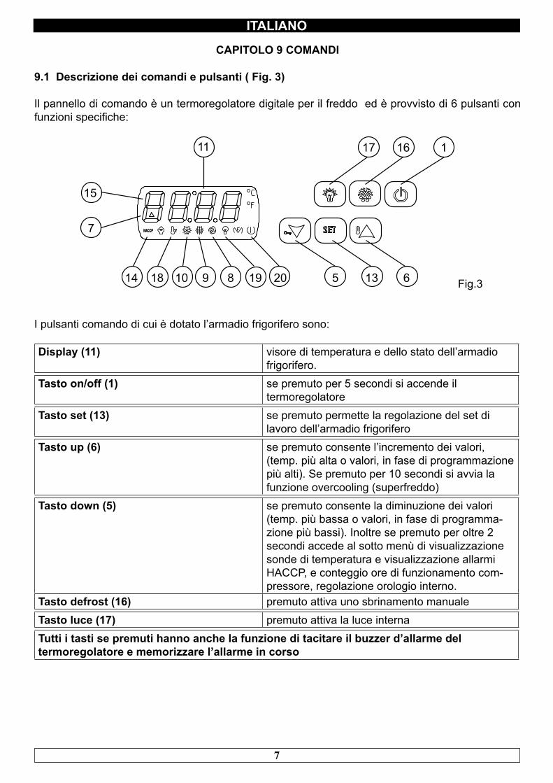
9.1 Descrizione dei comandi e pulsanti ( Fig. 3)
Il pannello di comando è un termoregolatore digitale per il freddo ed è provvisto di 6 pulsanti con funzioni specifiche:
11
15
7
14 18 10 9 8 19 20 5 13 6
17 16 1
Fig.3
I pulsanti comando di cui è dotato l’armadio frigorifero sono:
Display (11) visore di temperatura e dello stato dell’armadio frigorifero.
Tasto on/off (1) se premuto per 5 secondi si accende il termoregolatore
Tasto set (13) se premuto permette la regolazione del set di lavoro dell’armadio frigorifero
Tasto up (6) se premuto consente l’incremento dei valori, (temp. più alta o valori, in fase di programmazione più alti). Se premuto per 10 secondi si avvia la funzione overcooling (superfreddo)
Tasto down (5) se premuto consente la diminuzione dei valori (temp. più bassa o valori, in fase di programma-zione più bassi). Inoltre se premuto per oltre 2 secondi accede al sotto menù di visualizzazione sonde di temperatura e visualizzazione allarmi HACCP, e conteggio ore di funzionamento com-pressore, regolazione orologio interno.
Tasto defrost (16) premuto attiva uno sbrinamento manualeTasto luce (17) premuto attiva la luce internaTutti i tasti se premuti hanno anche la funzione di tacitare il buzzer d’allarme del termoregolatore e memorizzare l’allarme in corso
8
ITALIANO
9.2 INDICAZIONI RELATIVE ALL’USO
9.2.1 AvviamentoPrima di effettuare l’avviamento dell’armadio frigorifero è necessario verificare che il collegamento elettrico e l’allacciamento siano stati realizzati come previsto nel capitolo 15.
Verificare la presenza tensione, icona 20 accesa e display spento.
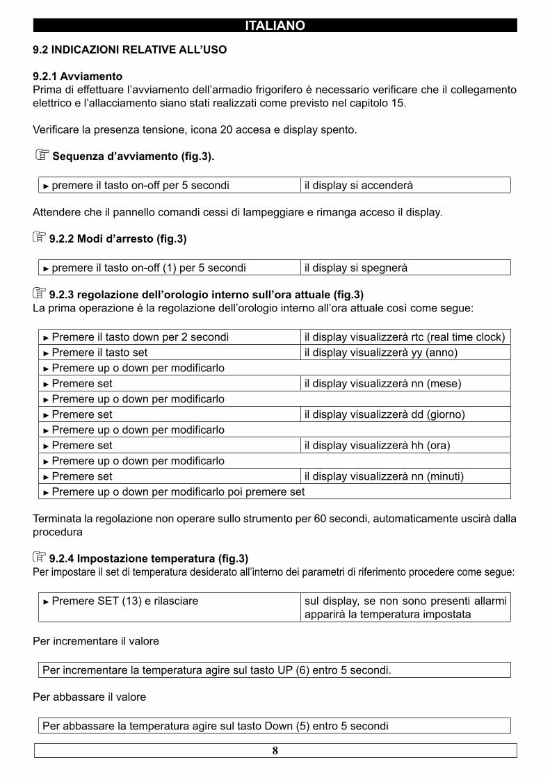
Sequenza d’avviamento (fig.3).
► premere il tasto on-off per 5 secondi il display si accenderà
Attendere che il pannello comandi cessi di lampeggiare e rimanga acceso il display.
9.2.2 Modi d’arresto (fig.3)
► premere il tasto on-off (1) per 5 secondi il display si spegnerà
9.2.3 regolazione dell’orologio interno sull’ora attuale (fig.3) La prima operazione è la regolazione dell’orologio interno all’ora attuale così come segue:
► Premere il tasto down per 2 secondi il display visualizzerà rtc (real time clock)► Premere il tasto set il display visualizzerà yy (anno)► Premere up o down per modificarlo► Premere set il display visualizzerà nn (mese)► Premere up o down per modificarlo► Premere set il display visualizzerà dd (giorno)► Premere up o down per modificarlo► Premere set il display visualizzerà hh (ora)► Premere up o down per modificarlo► Premere set il display visualizzerà nn (minuti)► Premere up o down per modificarlo poi premere set
Terminata la regolazione non operare sullo strumento per 60 secondi, automaticamente uscirà dalla procedura
9.2.4 Impostazione temperatura (fig.3) Per impostare il set di temperatura desiderato all’interno dei parametri di riferimento procedere come segue:
► Premere SET (13) e rilasciare sul display, se non sono presenti allarmi apparirà la temperatura impostata
Per incrementare il valore
Per incrementare la temperatura agire sul tasto UP (6) entro 5 secondi.
Per abbassare il valore
Per abbassare la temperatura agire sul tasto Down (5) entro 5 secondi
9
ITALIANOLo strumento memorizza automaticamente l’ultimo valore di temperatura impostato
9.2.5 Sbrinamento automatico e manuale (fig.3)L’armadio frigorifero è impostato, dalla fabbrica per poter effettuare lo sbrinamento automatico ad intervalli prestabiliti come segue:
• Gamma TNV (temperatura normale ventilata) uno sbrinamento di tipo “per fermata del compres-sore” di durata max 30 minuti ogni 8 ore di funzionamento.• Gamma TNBV (temperatura normale bassa, ventilata) uno sbrinamento tipo “ad attivazione resi-stenze elettriche” di durata max 30 minuti ogni 8 ore di funzionamento.• Gamma BTV (bassa temperatura, ventilata) uno sbrinamento tipo “ad attivazione resistenze elet-triche” di durata max 30 minuti ogni 6 ore di funzionamento del compressore.• Gamma TN-PE (temperatura normale pesce) uno sbrinamento tipo “ad attivazione resistenze elettriche” di durata max 30 minuti ogni 6 ore di funzionamento.
E’ possibile impostare altre modalità di sbrinamento quali: (a tempo di funzionamento compressore, a temperatura evaporatore, ad orario prestabilito).
Per modificare le modalità di sbrinamento vedere i parametri nella sezione service.
L’utilizzatore può effettuare uno sbrinamento manuale, secondo le proprie necessità, agendo come segue
► premere per oltre 5 secondi, il tasto defrost (16)
NB. durante il ciclo di sbrinamento automatico e manuale il led DEF rimarrà acceso, al termine del ciclo di sbrinamento l’indicatore si spegne e l’armadio frigorifero riprende automaticamente il ciclo normale di funzionamento.
Funzionamento per ALTA o BASSA percentuale di umidità il regolatore è impostato per il funzionamento ad ALTA umidità RhH
Tenere premuto contemporaneamente i tasti SET (13) e UP (6) per più di 4 secondi per il funzionamento a BASSA umidità RhL
Per per il funzionamento ad ALTA umidità RhH ripetere l’operazione
9.2.6 Blocco tastiera (fig.3)
Tenendo premuto contemporaneamente i tasti ON standby (1) e DOWN (5) per più di 4 secondi la tastiera sarà bloccata.
Per sbloccare ripetere l’operazione.
10
ITALIANO
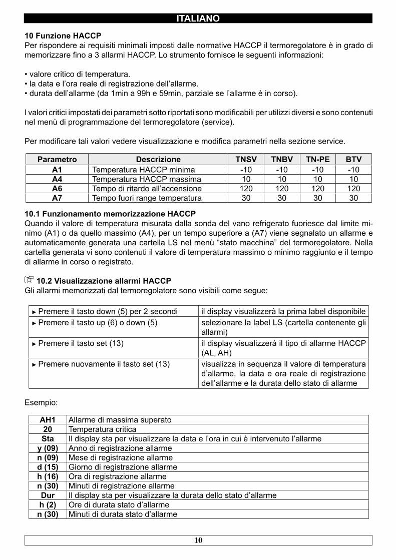
10 Funzione HACCPPer rispondere ai requisiti minimali imposti dalle normative HACCP il termoregolatore è in grado di memorizzare fino a 3 allarmi HACCP. Lo strumento fornisce le seguenti informazioni:
• valore critico di temperatura.• la data e l’ora reale di registrazione dell’allarme.• durata dell’allarme (da 1min a 99h e 59min, parziale se l’allarme è in corso).
I valori critici impostati dei parametri sotto riportati sono modificabili per utilizzi diversi e sono contenuti nel menù di programmazione del termoregolatore (service).
Per modificare tali valori vedere visualizzazione e modifica parametri nella sezione service.
Parametro Descrizione TNSV TNBV TN-PE BTVA1 Temperatura HACCP minima -10 -10 -10 -10A4 Temperatura HACCP massima 10 10 10 10A6 Tempo di ritardo all’accensione 120 120 120 120A7 Tempo fuori range temperatura 30 30 30 30
10.1 Funzionamento memorizzazione HACCPQuando il valore di temperatura misurata dalla sonda del vano refrigerato fuoriesce dal limite mi-nimo (A1) o da quello massimo (A4), per un tempo superiore a (A7) viene segnalato un allarme e automaticamente generata una cartella LS nel menù “stato macchina” del termoregolatore. Nella cartella generata vi sono contenuti il valore di temperatura massimo o minimo raggiunto e il tempo di allarme in corso o registrato.
10.2 Visualizzazione allarmi HACCPGli allarmi memorizzati dal termoregolatore sono visibili come segue:
► Premere il tasto down (5) per 2 secondi il display visualizzerà la prima label disponibile► Premere il tasto up (6) o down (5) selezionare la label LS (cartella contenente gli
allarmi)► Premere il tasto set (13) il display visualizzerà il tipo di allarme HACCP
(AL, AH)► Premere nuovamente il tasto set (13) visualizza in sequenza il valore di temperatura
d’allarme, la data e ora reale di registrazione dell’allarme e la durata dello stato di allarme
Esempio:
AH1 Allarme di massima superato20 Temperatura criticaSta Il display sta per visualizzare la data e l’ora in cui è intervenuto l’allarme
y (09) Anno di registrazione allarme n (09) Mese di registrazione allarmed (15) Giorno di registrazione allarmeh (16) Ora di registrazione allarmen (30) Minuti di registrazione allarmeDur Il display sta per visualizzare la durata dello stato d’allarmeh (2) Ore di durata stato d’allarmen (30) Minuti di durata stato d’allarme
11
ITALIANO
Nell’esempio sopra riportato il termoregolatore ha registrato un allarme di superamento massima temperatura (AH1) a 20°C il 15 settembre 2009 alle ore 16.30 è restato in stato d’allarme 2 ore e 30 minuti.Per uscire dalla visualizzazione allarmi HACCP premere il tasto ON/OFF (1) o non operare su alcun tasto per 15 secondi.
10.3 Cancellazione dell’elenco degli allarmi HACCPPer cancellare la cartella allarmi operare come segue:
► Premere il tasto down (5) per 2 secondi► Premere il tasto up o down per selezionare la label rLS► Premere set (13) visualizzerà 0► Premere il tasto up (6) entro 15 secondi impostare il valore 149► Premere set (13) e non operare per 15 secondiil display visualizzerà ------ lampeggiante per 4 secondi e l’icona HACCP si spegnerà
Se non vi è alcun allarme in memoria la label rLS non verrà visualizzata. Se non si cancellerà la cartella allarmi, un nuovo allarme, dopo tre eventi HACCP sovrascriverà quello meno recente.
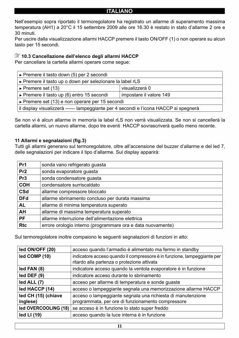
11 Allarmi e segnalazioni (fig.3)Tutti gli allarmi generano sul termoregolatore, oltre all’accensione del buzzer d’allarme e del led 7, delle segnalazioni per indicare il tipo d’allarme. Sul display apparirà:
Pr1 sonda vano refrigerato guastaPr2 sonda evaporatore guastaPr3 sonda condensatore guastaCOH condensatore surriscaldatoCSd allarme compressore bloccatoDFd allarme sbrinamento concluso per durata massimaAL allarme di minima temperatura superatoAH allarme di massima temperatura superatoPF allarme interruzione dell’alimentazione elettricaRtc errore orologio interno (programmare ora e data nuovamente)
Sul termoregolatore inoltre compaiono le seguenti segnalazioni di funzioni in atto:
led ON/OFF (20) acceso quando l’armadio è alimentato ma fermo in standbyled COMP (10) indicatore acceso quando il compressore è in funzione, lampeggiante per
ritardo alla partenza o protezione attivataled FAN (8) indicatore acceso quando la ventola evaporatore è in funzioneled DEF (9) indicatore acceso durante lo sbrinamentoled ALL (7) acceso per allarme di temperatura e sonde guasteled HACCP (14) acceso o lampeggiante segnala una memorizzazione allarme HACCPled CH (15) (chiave inglese)
acceso o lampeggiante segnala una richiesta di manutenzione programmata, per ore di funzionamento compressore
led OVERCOOLING (18) se acceso è in funzione lo stato super freddoled LI (19) acceso quando la luce interna è in funzione
12
ITALIANO
CAPITOLO 12 LIVELLO DI RUMOROSITA’
L’armadio frigorifero è stato progettato e costruito in modo tale che i rischi dovuti all’emissione di rumore aereo siano ridotti al livello minimo (vedi schede tecniche).
CAPITOLO 13 MATERIALI E FLUIDI IMPIEGATI
I materiali a contatto o che possono venire a contatto con i prodotti alimentari sono conformi alle direttive in materia.L’armadio frigorifero è stato progettato e costruito in modo tale che detti materiali possano essere puliti prima di ogni utilizzo.I fluidi frigorigeni utilizzati R404A/R290 sono conformi alle disposizioni di legge in materia (vedi Tabella 1).L’ R404A è un gas fluorurato trattato dal Protocollo di Kyoto ha un potenziale GWP di 3300
Per gli armadi frigoriferi contenenti R290: l’R290 (Propano) è un gas naturale senza alcun effetto sull’ambiente ma infiammabile è per questo contenuto nell’impianto in quantità minima prescritta dalle norme sui gas infiammabili e sigillato ermeticamente. Prima di ogni intervento sul sistema frigorifero leggere attentamente l’allegato AVVERTENZE PER INTERVENTI DI RIPARAZIONE SU APPARECCHI CON GAS REFRIGERANTE R290 (PROPANO) in dotazione con il manuale uso e manutenzione.
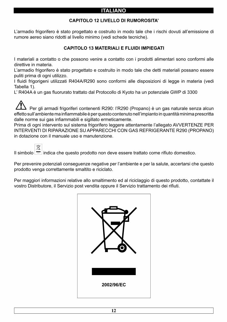
Il simbolo indica che questo prodotto non deve essere trattato come rifiuto domestico.
Per prevenire potenziali conseguenze negative per l’ambiente e per la salute, accertarsi che questo prodotto venga correttamente smaltito e riciclato.
Per maggiori informazioni relative allo smaltimento ed al riciclaggio di questo prodotto, contattate il vostro Distributore, il Servizio post vendita oppure il Servizio trattamento dei rifiuti.
13
ITALIANO
CAPITOLO 14 TRASPORTO E MOVIMENTAZIONE
Il trasporto e la movimentazione dell’armadio frigorifero devono esclusivamente avvenire mantenendo la posizione verticale, rispettando le indicazioni poste sull’imballo.
Il fabbricante si esime da qualsiasi responsabilità per inconvenienti dovuti al trasporto effettuato in condizioni diverse da quelle specificate in precedenza. Gli accessori a corredo dell’armadio frigorifero ( guide, griglie, vaschette, vassoi ) sono confezionati a parte e posizionati all’interno del mobile.
L’armadio frigorifero è fissato su un basamento di legno mediante viti e confezionata con imballi in polietilene, cartone, gabbia o cassa.
Per quanto riguarda lo smaltimento dell’imballo è necessario fare riferimento alle normative vigenti nel vostro paese.
La movimentazione dell’armadio frigorifero deve essere effettuata utilizzando un carrello sollevatore o transpallets provvisto di forche idonee ( lunghezza almeno pari a 2/3 del mobile ) .Le dimensioni e le masse degli armadi frigoriferi imballati sono rappresentate in Tabella1.I limiti di impilabilità e la posizione del baricentro sono indicati sulla targhetta dell’imballo.
14.1 Operazioni di posizionamentoPoiché l’errato posizionamento dell’armadio frigorifero può recare danno allo stesso, pregiudicarne il buon funzionamento e dar luogo a rischi per il personale, l’installatore deve rispettare le seguenti norme generali:
- posizionare l’armadio frigorifero mantenendo una distanza minima di cm 3 da qualsiasi parete- l’ambiente deve essere sufficientemente aerato- posizionare l’armadio frigorifero lontano da fonti di calore- evitare l’esposizione solare diretta- rimuovere l’imballo di polietilene, cartone o legno
Il polietilene è pericoloso per i bambini
- rimuovere eventuali accessori a corredo esterni
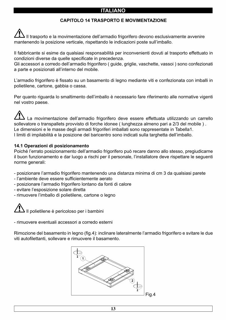
Rimozione del basamento in legno (fig.4): inclinare lateralmente l’armadio frigorifero e svitare le due viti autofilettanti, sollevare e rimuovere il basamento.
Fig.4
14
ITALIANO
utilizzare guanti di protezione nel maneggiare l’imballo in legno e il basamento in legno.
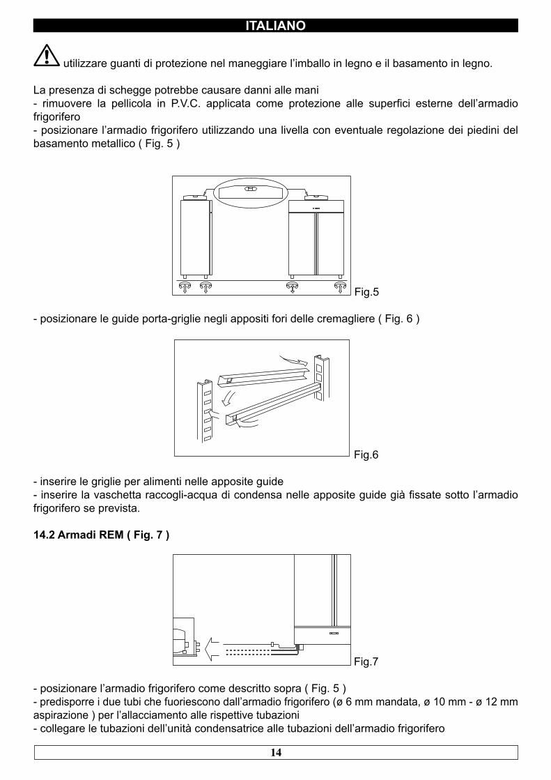
La presenza di schegge potrebbe causare danni alle mani- rimuovere la pellicola in P.V.C. applicata come protezione alle superfici esterne dell’armadio frigorifero- posizionare l’armadio frigorifero utilizzando una livella con eventuale regolazione dei piedini del basamento metallico ( Fig. 5 )
Fig.5
- posizionare le guide porta-griglie negli appositi fori delle cremagliere ( Fig. 6 )
Fig.6
- inserire le griglie per alimenti nelle apposite guide- inserire la vaschetta raccogli-acqua di condensa nelle apposite guide già fissate sotto l’armadio frigorifero se prevista.
14.2 Armadi REM ( Fig. 7 )
Fig.7
- posizionare l’armadio frigorifero come descritto sopra ( Fig. 5 )- predisporre i due tubi che fuoriescono dall’armadio frigorifero (ø 6 mm mandata, ø 10 mm - ø 12 mm aspirazione ) per l’allacciamento alle rispettive tubazioni - collegare le tubazioni dell’unità condensatrice alle tubazioni dell’armadio frigorifero
15
ITALIANO
- effettuare il vuoto e successivamente la carica di fluido frigorigeno- effettuare il collegamento elettrico dell’armadio frigorifero all’unità condensatrice- effettuare un test funzionale per verificare la corretta carica di gas.
CAPITOLO 15 CABLAGGIO E ALLACCIAMENTO ELETTRICO
L’impianto e l’allacciamento elettrico devono essere eseguiti da personale qualificato. Prima dell’installazione effettuare la misura dell’impedenza di rete; il valore di impedenza per il collegamento alla rete non deve superare 0,075 ohm.
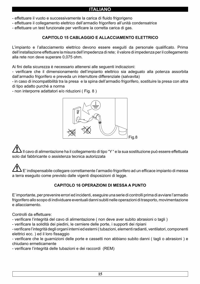
Ai fini della sicurezza è necessario attenersi alle seguenti indicazioni:- verificare che il dimensionamento dell’impianto elettrico sia adeguato alla potenza assorbita dall’armadio frigorifero e preveda un interruttore differenziale (salvavita)- in caso di incompatibilità tra la presa e la spina dell’armadio frigorifero, sostituire la presa con altra di tipo adatto purché a norma- non interporre adattatori e/o riduzioni ( Fig. 8 )
Fig.8
Il cavo di alimentazione ha il collegamento di tipo “Y “ e la sua sostituzione può essere effettuata solo dal fabbricante o assistenza tecnica autorizzata
E’ indispensabile collegare correttamente l’armadio frigorifero ad un efficace impianto di messa a terra eseguito come previsto dalle vigenti disposizioni di legge.
CAPITOLO 16 OPERAZIONI DI MESSA A PUNTO
E’ importante, per prevenire errori ed incidenti, eseguire una serie di controlli prima di avviare l’armadio frigorifero allo scopo di individuare eventuali danni subiti nelle operazioni di trasporto, movimentazione e allacciamento.
Controlli da effettuare:- verificare l’integrità del cavo di alimentazione ( non deve aver subito abrasioni o tagli )- verificare la solidità dei piedini, le cerniere delle porte, i supporti dei ripiani- verificare l’integrità degli organi interni ed esterni ( tubazioni, elementi radianti, ventilatori, componenti elettrici ecc. ) ed il loro fissaggio- verificare che le guarnizioni delle porte e cassetti non abbiano subito danni ( tagli o abrasioni ) e chiudano ermeticamente- verificare l’integrità delle tubazioni e dei raccordi (REM)
16
ITALIANO
CAPITOLO 17 REINSTALLAZIONE
E’ necessario rispettare la seguente procedura:- scollegare il cavo di alimentazione dalla presa di corrente- la movimentazione va effettuata come descritto nel capitolo 14- per il nuovo piazzamento e allacciamento si rinvia ai par. 14.1- procedere all’eventuale recupero del gas refrigerante in accordo alle normative vigenti nel vostro paese (REM)
17
ENGLISH
Thank you for choosing this product.
Please read the warnings contained in this manual carefully, as they provide important informationregarding safe operation and maintenance.Make sure to keep this manual for any future reference by the various operators.
In some parts of the manual, the symbol appears, indicating an important warning that mustbe observed for safety purposes.
CHAPTER 1 BOUNDARY CHARACTERISTICS OF OPERATION
The refrigerated cabinet has been designed and built to operate in optimal conditions at temperatures of up to +10°C and +43°C (+10°C and +32°C models with glass door), with adequate air circulation. In places with characteristics that are different from the requirements, the stated performance cannot be guaranteed.The supply voltage must be 230V +/- 10% 50Hz as standard, or as indicated on the EC label.The refrigerated cabinet may only be used within the temperature limits specified by the manufacturer; to identify the correct operating range, read the letters after the last digit of the model shown on the EC label and compare it with the table below:
Serie TemperatureTNV +2° +10°CTNBV -2° +10°CBTV -10° -22°C / 10° -25°C (PASTRY ICE)BTST - 12° - 25°CTNS PE -5° +5°C
The refrigerated cabinet complies with the European directives as described in detail in the Annex “EC Declaration of Conformity”
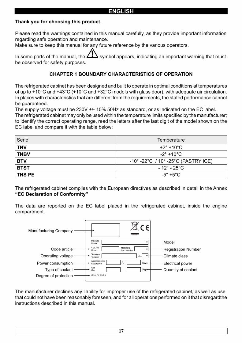
The data are reported on the EC label placed in the refrigerated cabinet, inside the engine compartment.
A Kw
Kg
CL.
MatricolaSer. Number
ModelloModel
Cod.ArtCode
TensioneTension
AssorbimentoAbsorption
GasGaz
IP20, CLASS 1
Model
Registration NumberClimate class
Electrical powerQuantity of coolant
Manufacturing Company
Code articleOperating voltage
Power consumptionType of coolant
Degree of protection
The manufacturer declines any liability for improper use of the refrigerated cabinet, as well as usethat could not have been reasonably foreseen, and for all operations performed on it that disregardthe instructions described in this manual.
18
ENGLISH
The main general safety standards are listed below:
- Do not use or place electrical devices inside the refrigerated compartments if they are not of thetype recommended by the manufacturer- Do not touch the refrigerated cabinet with damp or wet hands or feet- Do not use the refrigerated cabinet barefoot- Do not insert screwdrivers or other objects between the guards or moving parts- Do not pull the power cord to unplug the refrigerated cabinet from the electricity network- The refrigerated cabinet is not intended to be used by persons (including children) with physical ormental problems, or lack of experience and knowledge, unless they are controlled or instructed inusing the unit by a person responsible for their safety. Children must be supervised to ensure thatthey do not play with the appliance.- Before carrying out any cleaning or maintenance, disconnect the refrigerated cabinet from the mains power supply by turning off the main switch and pulling the plug- In the event of failure and/or malfunction of the refrigerated cabinet, turn it off and to refrain fromany attempt to repair or intervene directly. It is necessary to exclusively contact a qualified technician.
The refrigerated cabinet is composed of a modular monocoque coated with different materials andinsulated with polyurethane foam of density 42 kg/m3.
In the design and construction, all measures have been adopted to ensure a refrigerated cabinetthat complies with safety and hygiene requirements, such as: rounded interior corners, deep drawing with drain on the outside for the condensate liquids, no rough surfaces, fixed guards on moving ordangerous parts.
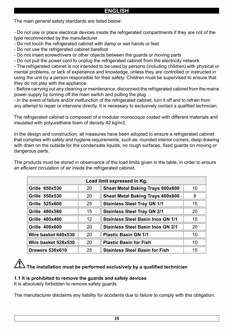
The products must be stored in observance of the load limits given in the table, in order to ensurean efficient circulation of air inside the refrigerated cabinet.
Load limit expressed in Kg.Grille 650x530 20 Sheet Metal Baking Trays 800x600 10Grille 550x530 20 Sheet Metal Baking Trays 400x600 8Grille 525x600 25 Stainless Steel Tray GN 1/1 15Grille 480x580 15 Stainless Steel Tray GN 2/1 20Grille 480x480 12 Stainless Steel Basin Inox GN 1/1 15Grille 400x600 20 Stainless Steel Basin Inox GN 2/1 20Wire basket 640x530 20 Plastic Basin GN 1/1 10Wire basket 528x530 20 Plastic Basin for Fish 10Drawers 530x610 25 Stainless Steel Basin for Fish 15
The installation must be performed exclusively by a qualified technician
1.1 It is prohibited to remove the guards and safety devicesIt is absolutely forbidden to remove safety guards.
The manufacturer disclaims any liability for accidents due to failure to comply with this obligation.
19
ENGLISH
1.2 Information on emergency operations in the event of fire- disconnect the refrigerated cabinet from the electrical outlet or cut off the main power supply- do not use water jets- use dry chemical or CO2 extinguishers
CHAPTER 2 CLEANING THE REFRIGERATOR
Since the refrigerated cabinet will be used to store food, cleaning is necessary for hygiene and health protection purposes. The cleaning of the refrigerated cabinet has already been carried out at thefactory. It is suggested, however, to carry out an additional cleaning of the internal parts before use, making sure that the power cord is unplugged.
2.1 Cleaning the interior and exterior cabinetFor this purpose the following are indicated- the cleaning products: water and mild, non-abrasive detergents. DO NOT USE SOLVENTS ANDTHINNERS- methods for cleaning: wash the interior and exterior parts with warm water and mild soap or with a cloth or sponge with suitable products- disinfection: avoid substances that can alter the organoleptic characteristics of the food- rinsing: cloth or sponge soaked in warm water. DO NOT USE WATER JETS- frequency: weekly is recommended, the user can set different frequencies depending on the typeof food being stored.
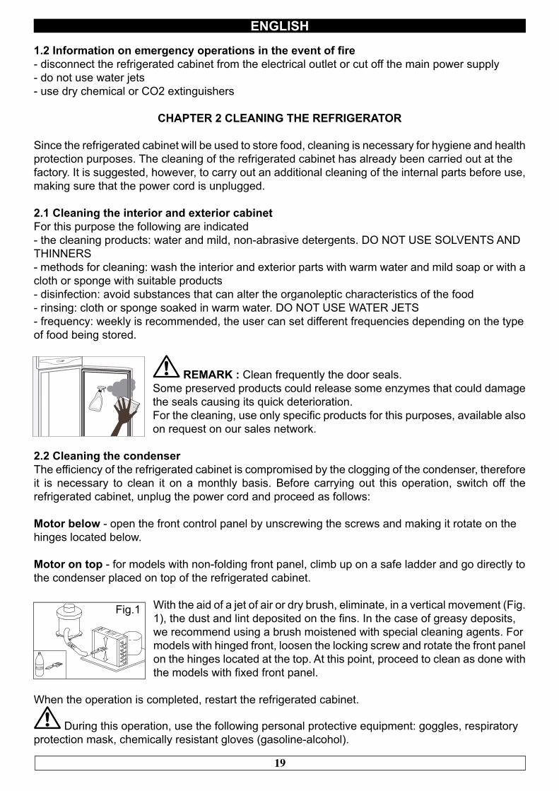
REMARK : Clean frequently the door seals.Some preserved products could release some enzymes that could damage the seals causing its quick deterioration. For the cleaning, use only specific products for this purposes, available also on request on our sales network.
2.2 Cleaning the condenserThe efficiency of the refrigerated cabinet is compromised by the clogging of the condenser, therefore it is necessary to clean it on a monthly basis. Before carrying out this operation, switch off the refrigerated cabinet, unplug the power cord and proceed as follows:
Motor below - open the front control panel by unscrewing the screws and making it rotate on thehinges located below.
Motor on top - for models with non-folding front panel, climb up on a safe ladder and go directly tothe condenser placed on top of the refrigerated cabinet.
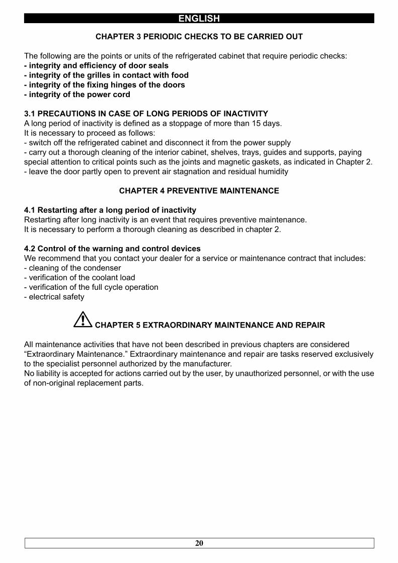
With the aid of a jet of air or dry brush, eliminate, in a vertical movement (Fig. 1), the dust and lint deposited on the fins. In the case of greasy deposits,we recommend using a brush moistened with special cleaning agents. Formodels with hinged front, loosen the locking screw and rotate the front panel on the hinges located at the top. At this point, proceed to clean as done withthe models with fixed front panel.
When the operation is completed, restart the refrigerated cabinet.
During this operation, use the following personal protective equipment: goggles, respiratoryprotection mask, chemically resistant gloves (gasoline-alcohol).
ALCOOL
Fig.1
20
ENGLISH
CHAPTER 3 PERIODIC CHECKS TO BE CARRIED OUT
The following are the points or units of the refrigerated cabinet that require periodic checks:- integrity and efficiency of door seals- integrity of the grilles in contact with food- integrity of the fixing hinges of the doors- integrity of the power cord
3.1 PRECAUTIONS IN CASE OF LONG PERIODS OF INACTIVITYA long period of inactivity is defined as a stoppage of more than 15 days.It is necessary to proceed as follows:- switch off the refrigerated cabinet and disconnect it from the power supply- carry out a thorough cleaning of the interior cabinet, shelves, trays, guides and supports, payingspecial attention to critical points such as the joints and magnetic gaskets, as indicated in Chapter 2.- leave the door partly open to prevent air stagnation and residual humidity
CHAPTER 4 PREVENTIVE MAINTENANCE
4.1 Restarting after a long period of inactivityRestarting after long inactivity is an event that requires preventive maintenance.It is necessary to perform a thorough cleaning as described in chapter 2.
4.2 Control of the warning and control devicesWe recommend that you contact your dealer for a service or maintenance contract that includes:- cleaning of the condenser- verification of the coolant load- verification of the full cycle operation- electrical safety
CHAPTER 5 EXTRAORDINARY MAINTENANCE AND REPAIR
All maintenance activities that have not been described in previous chapters are considered“Extraordinary Maintenance.” Extraordinary maintenance and repair are tasks reserved exclusivelyto the specialist personnel authorized by the manufacturer.No liability is accepted for actions carried out by the user, by unauthorized personnel, or with the use of non-original replacement parts.
21
ENGLISH
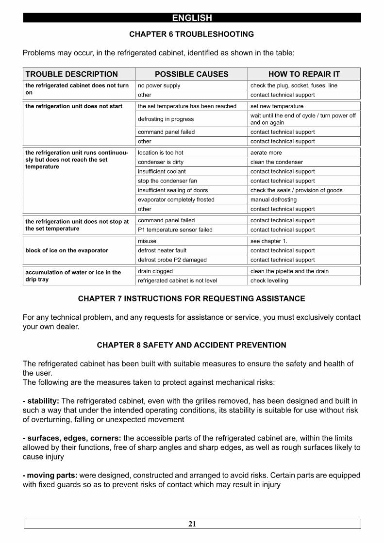
CHAPTER 6 TROUBLESHOOTING
Problems may occur, in the refrigerated cabinet, identified as shown in the table:
TROUBLE DESCRIPTION POSSIBLE CAUSES HOW TO REPAIR ITthe refrigerated cabinet does not turnon
no power supply check the plug, socket, fuses, lineother contact technical support
the refrigeration unit does not start the set temperature has been reached set new temperature
defrosting in progress wait until the end of cycle / turn power offand on again
command panel failed contact technical supportother contact technical support
the refrigeration unit runs continuou-sly but does not reach the settemperature
location is too hot aerate morecondenser is dirty clean the condenserinsufficient coolant contact technical supportstop the condenser fan contact technical supportinsufficient sealing of doors check the seals / provision of goodsevaporator completely frosted manual defrostingother contact technical support
the refrigeration unit does not stop atthe set temperature
command panel failed contact technical supportP1 temperature sensor failed contact technical support
block of ice on the evaporatormisuse see chapter 1.defrost heater fault contact technical supportdefrost probe P2 damaged contact technical support
accumulation of water or ice in thedrip tray
drain clogged clean the pipette and the drainrefrigerated cabinet is not level check levelling
CHAPTER 7 INSTRUCTIONS FOR REQUESTING ASSISTANCE
For any technical problem, and any requests for assistance or service, you must exclusively contact your own dealer.
CHAPTER 8 SAFETY AND ACCIDENT PREVENTION
The refrigerated cabinet has been built with suitable measures to ensure the safety and health ofthe user.The following are the measures taken to protect against mechanical risks:
- stability: The refrigerated cabinet, even with the grilles removed, has been designed and built insuch a way that under the intended operating conditions, its stability is suitable for use without riskof overturning, falling or unexpected movement
- surfaces, edges, corners: the accessible parts of the refrigerated cabinet are, within the limitsallowed by their functions, free of sharp angles and sharp edges, as well as rough surfaces likely to cause injury
- moving parts: were designed, constructed and arranged to avoid risks. Certain parts are equipped with fixed guards so as to prevent risks of contact which may result in injury
22
ENGLISH
The following are the measures taken to protect against other risks:
- electricity: The refrigerated cabinet has been designed, built and equipped so as to prevent risks from electricity, in accordance with the specific legislation in force
- noise: The refrigerated cabinet has been designed and built in such a way that risks resulting from the emission of airborne noise are reduced to the minimum level
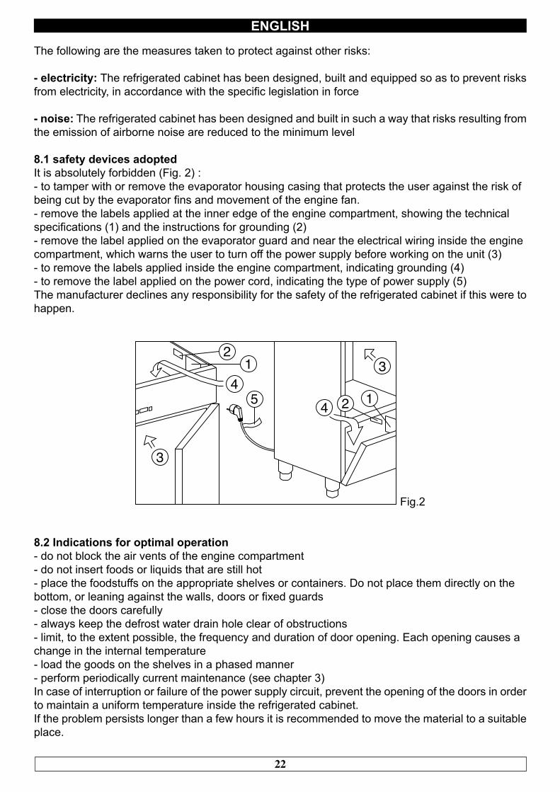
8.1 safety devices adoptedIt is absolutely forbidden (Fig. 2) :- to tamper with or remove the evaporator housing casing that protects the user against the risk ofbeing cut by the evaporator fins and movement of the engine fan.- remove the labels applied at the inner edge of the engine compartment, showing the technicalspecifications (1) and the instructions for grounding (2)- remove the label applied on the evaporator guard and near the electrical wiring inside the enginecompartment, which warns the user to turn off the power supply before working on the unit (3)- to remove the labels applied inside the engine compartment, indicating grounding (4)- to remove the label applied on the power cord, indicating the type of power supply (5)The manufacturer declines any responsibility for the safety of the refrigerated cabinet if this were to happen.
12
3
34
5 4 2 1
Fig.2
8.2 Indications for optimal operation- do not block the air vents of the engine compartment- do not insert foods or liquids that are still hot- place the foodstuffs on the appropriate shelves or containers. Do not place them directly on thebottom, or leaning against the walls, doors or fixed guards- close the doors carefully- always keep the defrost water drain hole clear of obstructions- limit, to the extent possible, the frequency and duration of door opening. Each opening causes achange in the internal temperature- load the goods on the shelves in a phased manner- perform periodically current maintenance (see chapter 3)In case of interruption or failure of the power supply circuit, prevent the opening of the doors in order to maintain a uniform temperature inside the refrigerated cabinet.If the problem persists longer than a few hours it is recommended to move the material to a suitable place.
23
ENGLISH
CHAPTER 9 CONTROLS
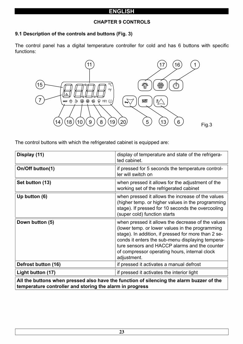
9.1 Description of the controls and buttons (Fig. 3)
The control panel has a digital temperature controller for cold and has 6 buttons with specific functions:
11
15
7
14 18 10 9 8 19 20 5 13 6
17 16 1
Fig.3
The control buttons with which the refrigerated cabinet is equipped are:
Display (11) display of temperature and state of the refrigera-ted cabinet.
On/Off button(1) if pressed for 5 seconds the temperature control-ler will switch on
Set button (13) when pressed it allows for the adjustment of theworking set of the refrigerated cabinet
Up button (6) when pressed it allows the increase of the values(higher temp. or higher values in the programmingstage). If pressed for 10 seconds the overcooling(super cold) function starts
Down button (5) when pressed it allows the decrease of the values(lower temp. or lower values in the programmingstage). In addition, if pressed for more than 2 se-conds it enters the sub-menu displaying tempera-ture sensors and HACCP alarms and the counterof compressor operating hours, internal clockadjustment.
Defrost button (16) if pressed it activates a manual defrostLight button (17) if pressed it activates the interior lightAll the buttons when pressed also have the function of silencing the alarm buzzer of thetemperature controller and storing the alarm in progress
24
ENGLISH
9.2 INSTRUCTIONS FOR USE
9.2.1 Start-upBefore starting up the refrigerated cabinet, make sure that the electrical connection and the connection have been made as indicated in Chapter 15.Check the presence of voltage, icon 20 on and display off.
Start-up sequence (fig.3).
► press the on-off button for 5 seconds the display will turn on
Wait for the control panel to stop flashing and for the display to remain on.
9.2.2 Stopping methods (fig.3)
► press the on-off button (1) for 5 seconds the display will turn off
9.2.3 3 adjustment of the internal clock to the current time (fig. 3)The first step is to adjust the internal clock to the current time as follows:
► press the down button for 2 seconds the RTC display (real time clock)► press the set button the display will show yy (year)► press up or down to change it► Press set the display will show nn (month)► press up or down to change it► Press set the display will show dd (day)► press up or down to change it► Press set the display will show hh (hour)► Press up or down to change it► Press set the display will show nn (minutes)► Press up or down to change it then press set
After the adjustment is finished, do not operate the instrument for 60 seconds, it will automaticallyexit the procedure
Setting the temperature (Fig. 3)To set the desired set temperature within the parameters of reference, proceed as follows:
► Press SET (13) and release on the display, if there are no alarms theset temperature will appear
To increase the value
To increase the temperature press the UP button (6) within 5 seconds.
To lower the temperature
To lower the temperature press the Down button (5) within 5 seconds
25
ENGLISH
The instrument automatically stores the last set temperature value
9.2.5 Automatic and manual defrost (Fig. 3)The refrigerated cabinet is factory-set to be able to defrost automatically at predetermined intervalsas follows:
• TNV Range (normal ventilated temperature) a defrost type “by means of stopping the compressor” lasting up to 30 minutes every 8 hours of operation.• TNBV Range (low normal temperature, ventilated) a defrost type “by means of activating the electric heaters” lasting up to 30 minutes every 8 hours of operation.• BTV Range (low temperature, ventilated) a defrost type “by means of activating the electric heaters” lasting up to 30 minutes every 6 hours of operation of the compressor.• TN-PE Range (normal fish temperature) a defrost type “by means of activating the electric heaters” lasting up to 30 minutes every 6 hours of operation.
It is possible to set other defrost modes, such as: (with compressor running time, with evaporatortemperature, with pre-set times).
To change the defrost mode see the parameters in the service section.
The user can perform a manual defrost, according to their needs, acting as follows
► press the defrost button (16) for 5 seconds
N.B.: during the automatic and manual defrost cycle the DEF LED will remain on, at the end of thedefrost cycle, the indicator turns off and the refrigerated cabinet automatically resumes the normalcycle of operation.
Operation with HIGH or LOW humidity percentagethe controller is set to operate at HIGH RhH humidity
Simultaneously press and hold the SET (13) and UP (6) buttons for more than 4 seconds foroperation at LOW humidity RhL
In order to operate at HIGH humidity RhH, repeat the operation
9.2.6 Keypad lock (fig.3)
By simultaneously holding down the standby ON (1) and DOWN (5) buttons for more than 4seconds, the keyboard will be locked.
To unlock repeat the operation.
26
ENGLISH
10 HACCP functionTo meet the minimum requirements of the HACCP regulations, the temperature controller is capable of storing up to 3 HACCP alarms. The instrument provides the following information:
• critical temperature value.• the actual date and time of alarm registration.• duration of the alarm (from 1min to 99h and 59min, partial if the alarm is in progress).
The set critical values of the parameters below can be modified for different uses and are contained in the programming menu of the temperature controller (service).
To change these values see viewing and editing parameters in the service section.
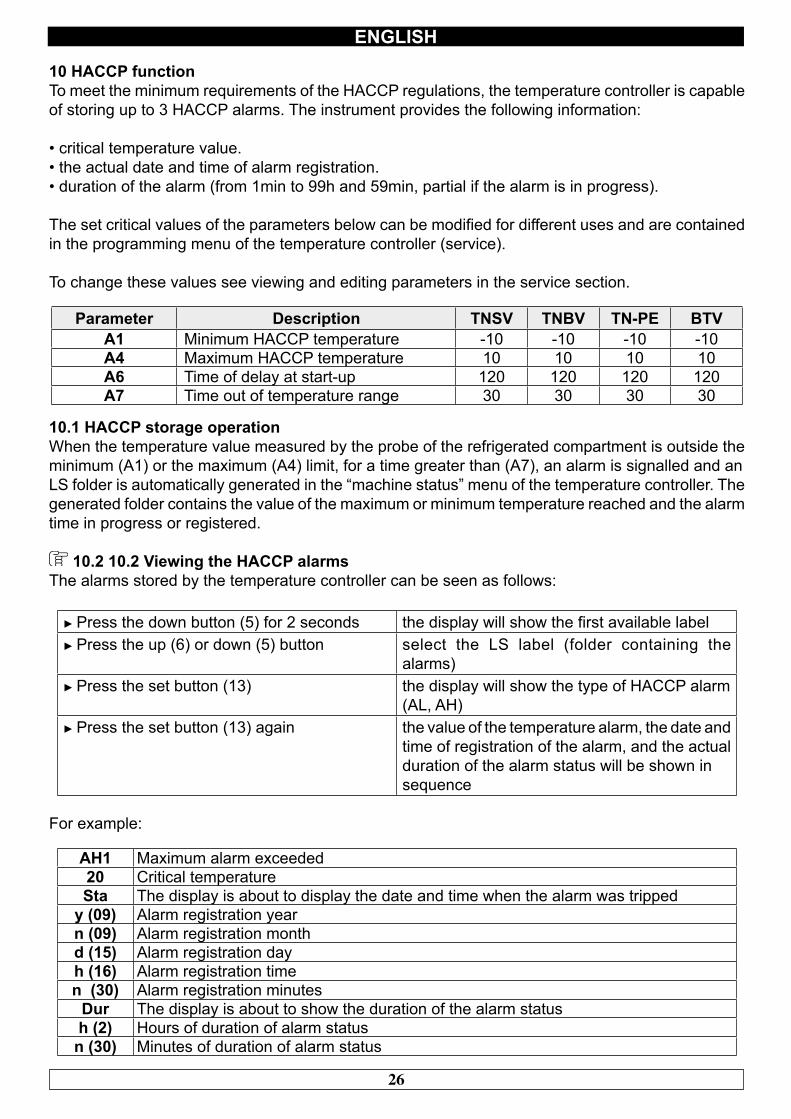
Parameter Description TNSV TNBV TN-PE BTVA1 Minimum HACCP temperature -10 -10 -10 -10A4 Maximum HACCP temperature 10 10 10 10A6 Time of delay at start-up 120 120 120 120A7 Time out of temperature range 30 30 30 30
10.1 HACCP storage operationWhen the temperature value measured by the probe of the refrigerated compartment is outside the minimum (A1) or the maximum (A4) limit, for a time greater than (A7), an alarm is signalled and anLS folder is automatically generated in the “machine status” menu of the temperature controller. The generated folder contains the value of the maximum or minimum temperature reached and the alarm time in progress or registered.
10.2 10.2 Viewing the HACCP alarmsThe alarms stored by the temperature controller can be seen as follows:
► Press the down button (5) for 2 seconds the display will show the first available label► Press the up (6) or down (5) button select the LS label (folder containing the
alarms)► Press the set button (13) the display will show the type of HACCP alarm
(AL, AH)► Press the set button (13) again the value of the temperature alarm, the date and
time of registration of the alarm, and the actual duration of the alarm status will be shown insequence
For example:
AH1 Maximum alarm exceeded20 Critical temperatureSta The display is about to display the date and time when the alarm was tripped
y (09) Alarm registration yearn (09) Alarm registration monthd (15) Alarm registration dayh (16) Alarm registration timen (30) Alarm registration minutes
Dur The display is about to show the duration of the alarm statush (2) Hours of duration of alarm statusn (30) Minutes of duration of alarm status
27
ENGLISH
In the above example the temperature controller has registered an alarm for exceeding the maximum temperature (AH1) at 20°C on 15th September 2009 at 16:30 and remained in a state of alarm for2 hours and 30 minutes.To exit from the HACCP alarm display press the ON/OFF button (1) or not operate any button for15 seconds.
10.3 Deleting the list of HACCP alarmsTo delate the alarms folder, proceed as follows:
► Press the down button (5) for 2 seconds► Press up or down button to select the rLS label► Press set (13) it will show 0► Press the up button (6) within 15 seconds set the value 149► Press set (13) and do not operate for 15 secondsthe display will show ------ flashing for 4 seconds and the HACCP icon will turn off
If there is no alarm in memory the label rLS will not be displayed. If the alarms folder is not cleared, a new, after three events HACCP alarm will overwrite the oldest one.
11 Alarms and signals (fig.3)All alarms generate, on the temperature controller, as well as the turning on of the alarm buzzer and LED 7, messages to indicate the type of alarm. The display will show:
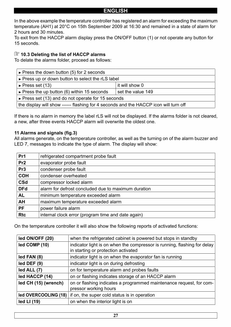
Pr1 refrigerated compartment probe faultPr2 evaporator probe faultPr3 condenser probe faultCOH condenser overheatedCSd compressor locked alarmDFd alarm for defrost concluded due to maximum durationAL minimum temperature exceeded alarmAH maximum temperature exceeded alarmPF power failure alarmRtc internal clock error (program time and date again)
On the temperature controller it will also show the following reports of activated functions:
led ON/OFF (20) when the refrigerated cabinet is powered but stops in standbyled COMP (10) indicator light is on when the compressor is running, flashing for delay
in starting or protection activatedled FAN (8) indicator light is on when the evaporator fan is runningled DEF (9) indicator light is on during defrostingled ALL (7) on for temperature alarm and probes faultsled HACCP (14) on or flashing indicates storage of an HACCP alarmled CH (15) (wrench) on or flashing indicates a programmed maintenance request, for com-
pressor working hoursled OVERCOOLING (18) if on, the super cold status is in operationled LI (19) on when the interior light is on
28
ENGLISH
CHAPTER 12 NOISE LEVEL
The refrigerated cabinet is designed and constructed so that risks resulting from the emission of airborne noise are reduced to the minimum level (see technical information).
CHAPTER 13 MATERIALS AND FLUID USED
The materials in contact or which may come into contact with foodstuffs comply with the relevantdirectives.The refrigerated cabinet has been designed and built in such a way that these materials can becleaned before each use.The coolants used R404A/R290 conform to the relevant provisions of law (see Table 1).R404A is a fluorinated gas covered by the Kyoto Protocol with a GWP potential of 3300
For refrigerated cabinets containing R290: R290 (Propane) is a natural gas with noeffect on the environment but it is flammable and therefore contained in the system in minimumquantities prescribed by regulations on flammable gas and it is hermetically sealed.Before any intervention on the coolant system, carefully read the attached INSTRUCTIONSFOR REPAIRS ON UNITS WITH R290 COOLANT GAS (PROPANE) supplied with the use andmaintenance manual.
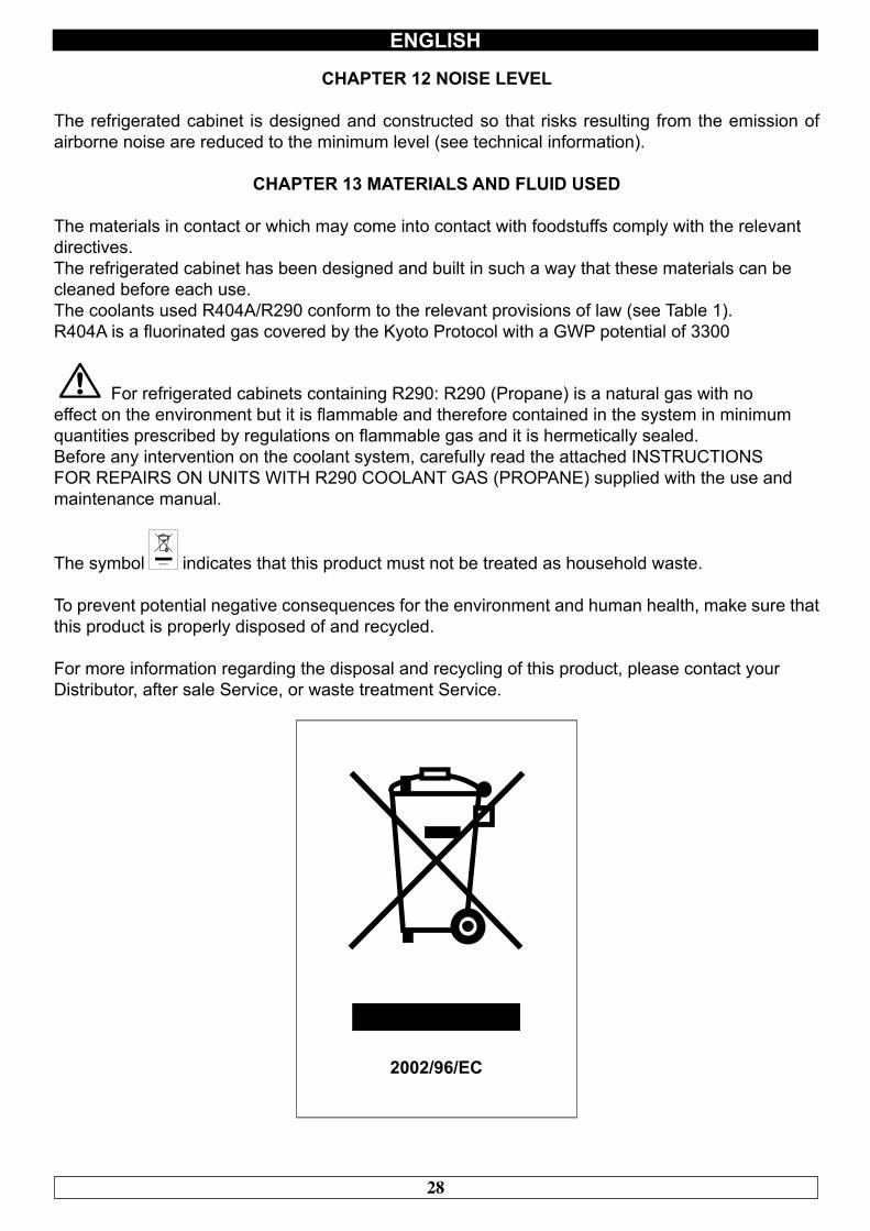
The symbol indicates that this product must not be treated as household waste.
To prevent potential negative consequences for the environment and human health, make sure that this product is properly disposed of and recycled.
For more information regarding the disposal and recycling of this product, please contact yourDistributor, after sale Service, or waste treatment Service.
29
ENGLISH
CHAPTER 14 TRANSPORT AND HANDLING
The transport and handling of the refrigerated cabinet must only be done while maintaining the vertical position, observing the markings on the packaging.
The manufacturer disclaims any liability for problems resulting from transport performed underconditions other than those specified above.The accessories of the refrigerated cabinet (guides, grilles, trays) are packaged separately and placed inside the unit.
The refrigerated cabinet is mounted on a wooden base with screws and packaged with polyethylene, carton, crate or boxes.
Regarding the disposal of the packaging it is necessary to refer to current regulations in your country.
The movement of the refrigerated cabinet shall be performed using a fork lift or pallet trucksequipped with suitable forks (length of at least 2/3 of the unit).The dimensions and masses of the refrigerated cabinets packed are shown in Table 1.The limits of stackability and the centre of gravity are indicated on the label of the package.
14.1 Positioning operationsSince the incorrect positioning of the refrigerated cabinet can cause damage to the same, jeopardizing its proper functioning and cause risks to the personnel, the installer must comply with the followinggeneral rules:- position the refrigerated cabinet keeping a minimum distance of 3 cm from any wall- the environment must be sufficiently ventilated- position the refrigerated cabinet away from heat sources- avoid exposure to direct sunlight- remove the polyethylene, cardboard or wood packaging
Polyethylene is dangerous for children
- remove any accessories with external connections
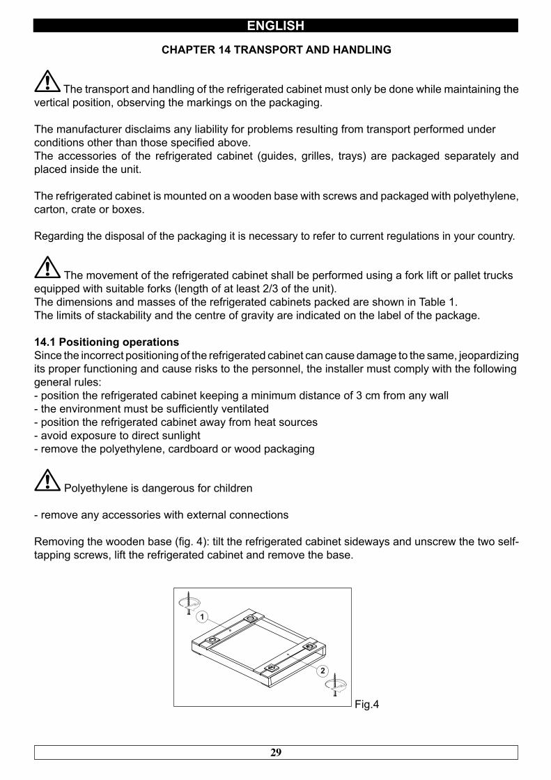
Removing the wooden base (fig. 4): tilt the refrigerated cabinet sideways and unscrew the two self-tapping screws, lift the refrigerated cabinet and remove the base.
Fig.4
30
ENGLISH
use protective gloves when handling the wooden packaging and the wooden base.
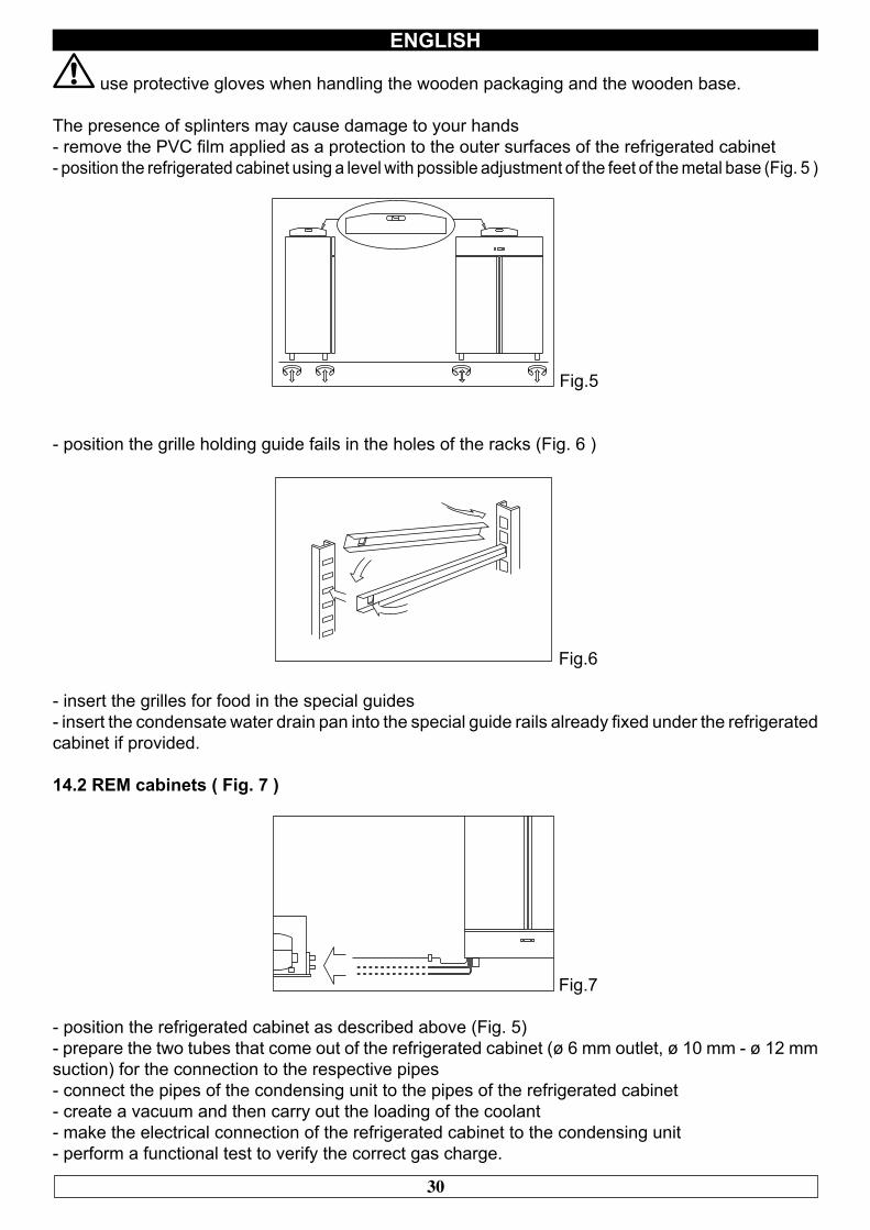
The presence of splinters may cause damage to your hands- remove the PVC film applied as a protection to the outer surfaces of the refrigerated cabinet- position the refrigerated cabinet using a level with possible adjustment of the feet of the metal base (Fig. 5 )
Fig.5
- position the grille holding guide fails in the holes of the racks (Fig. 6 )
Fig.6
- insert the grilles for food in the special guides- insert the condensate water drain pan into the special guide rails already fixed under the refrigerated cabinet if provided.
14.2 REM cabinets ( Fig. 7 )
Fig.7
- position the refrigerated cabinet as described above (Fig. 5)- prepare the two tubes that come out of the refrigerated cabinet (ø 6 mm outlet, ø 10 mm - ø 12 mm suction) for the connection to the respective pipes- connect the pipes of the condensing unit to the pipes of the refrigerated cabinet- create a vacuum and then carry out the loading of the coolant- make the electrical connection of the refrigerated cabinet to the condensing unit- perform a functional test to verify the correct gas charge.
31
ENGLISH
CHAPTER 15 ELECTRICAL WIRING AND CONNECTIONS
The electrical system and connection must be carried out by qualified personnel. Before installation, measure the impedance of the network, the impedance value for the connection to the network must not exceed 0.075 ohm.
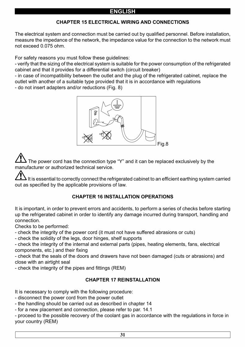
For safety reasons you must follow these guidelines:- verify that the sizing of the electrical system is suitable for the power consumption of the refrigerated cabinet and that it provides for a differential switch (circuit breaker)- in case of incompatibility between the outlet and the plug of the refrigerated cabinet, replace theoutlet with another of a suitable type provided that it is in accordance with regulations- do not insert adapters and/or reductions (Fig. 8)
Fig.8
The power cord has the connection type “Y” and it can be replaced exclusively by themanufacturer or authorized technical service.
It is essential to correctly connect the refrigerated cabinet to an efficient earthing system carried out as specified by the applicable provisions of law.
CHAPTER 16 INSTALLATION OPERATIONS
It is important, in order to prevent errors and accidents, to perform a series of checks before starting up the refrigerated cabinet in order to identify any damage incurred during transport, handling andconnection.Checks to be performed:- check the integrity of the power cord (it must not have suffered abrasions or cuts)- check the solidity of the legs, door hinges, shelf supports- check the integrity of the internal and external parts (pipes, heating elements, fans, electricalcomponents, etc.) and their fixing- check that the seals of the doors and drawers have not been damaged (cuts or abrasions) andclose with an airtight seal- check the integrity of the pipes and fittings (REM)
CHAPTER 17 REINSTALLATION
It is necessary to comply with the following procedure:- disconnect the power cord from the power outlet- the handling should be carried out as described in chapter 14- for a new placement and connection, please refer to par. 14.1- proceed to the possible recovery of the coolant gas in accordance with the regulations in force inyour country (REM)
32
ATTENZIONE!ISTRUZIONI RISERVATE A PERSONALE TECNICO AUTORIZZATO
Si avvisano gli utenti che qualsiasi intervento eseguito da personale non tecnico o non autorizzato produrrà la decadenza delle condizioni
di garanzia.
WARNING!INSTRUCTIONS STRICTLY RESERVED TO AUTHORIZED
TECHNICAL PERSONNEL
Every intervention executed by a non authorized technical personnelimplies a warranty decay.
33
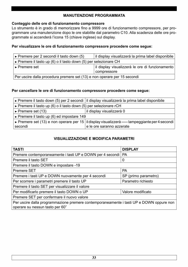
MANUTENZIONE PROGRAMMATA
Conteggio delle ore di funzionamento compressoreLo strumento è in grado di memorizzare fino a 9999 ore di funzionamento compressore, per pro-grammare una manutenzione dopo le ore stabilite dal parametro C10. Alla scadenza delle ore pro-grammate si accenderà l’icona 15 (chiave inglese) sul display.
Per visualizzare le ore di funzionamento compressore procedere come segue:
► Premere per 2 secondi il tasto down (5) il display visualizzerà la prima label disponibile► Premere il tasto up (6) o il tasto down (5) per selezionare CH► Premere set il display visualizzerà le ore di funzionamento
compressorePer uscire dalla procedura premere set (13) e non operare per 15 secondi
Per cancellare le ore di funzionamento compressore procedere come segue:
► Premere il tasto down (5) per 2 secondi il display visualizzerà la prima label disponibile► Premere il tasto up (6) o il tasto down (5) per selezionare rCH► Premere set (13) il display visualizzerà 0► Premere il tasto up (6) ed impostare 149► Premere set (13) e non operare per 15 secondi
il display visualizzerà ----- lampeggiante per 4 secondi e le ore saranno azzerate
VISUALIZZAZIONE E MODIFICA PARAMETRI
TASTI DISPLAYPremere contemporaneamente i tasti UP e DOWN per 4 secondi PAPremere il tasto SET 0Premere il tasto DOWN e impostare -19Premere SET PAPremere i tasti UP e DOWN nuovamente per 4 secondi SP (primo parametro)Per scorrere i parametri premere il tasto UP Parametro richiestoPremere il tasto SET per visualizzare il valorePer modificarlo premere il tasto DOWN o UP Valore modificatoPremere SET per confermare il nuovo valorePer uscire dalla programmazione premere contemporaneamente i tasti UP e DOWN oppure non operare su nessun tasto per 60”
34
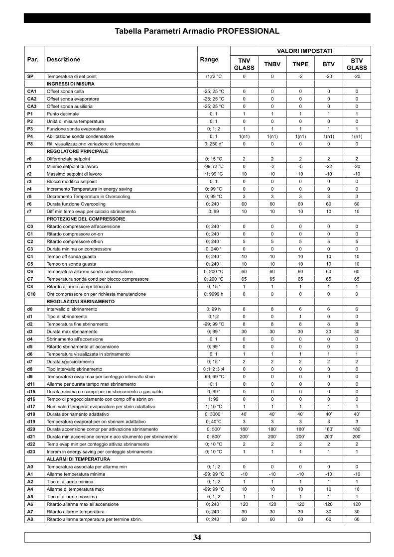
Tabella Parametri Armadio PROFESSIONAL
Par. Descrizione Range VALORI IMPOSTATI
TNVGLASS TNBV TNPE BTV BTV
GLASSSP Temperatura di set point r1;r2 °C 0 0 -2 -20 -20
INGRESSI DI MISURACA1 Offset sonda cella -25; 25 °C 0 0 0 0 0CA2 Offset sonda evaporatore -25; 25 °C 0 0 0 0 0CA3 Offset sonda ausiliaria -25; 25 °C 0 0 0 0 0P1 Punto decimale 0; 1 1 1 1 1 1P2 Unità di misura temperatura 0; 1 0 0 0 0 0P3 Funzione sonda evaporatore 0; 1; 2 1 1 1 1 1P4 Abilitazione sonda condensatore 0; 1 1(n1) 1(n1) 1(n1) 1(n1) 1(n1)P8 Rit. visualizzazione variazione di temperatura 0; 250 d” 0 0 0 0 0
REGOLATORE PRINCIPALEr0 Differenziale setpoint 0; 15 °C 2 2 2 2 2r1 Minimo setpoint di lavoro -99; r2 °C 0 -2 -5 -22 -20r2 Massimo setpoint di lavoro r1; 99 °C 10 10 10 -10 -10r3 Blocco modifica setpoint 0; 1 0 0 0 0 0r4 Incremento Temperatura in energy saving 0; 99 °C 0 0 0 0 0r5 Decremento Temperatura in Overcooling 0; 99 °C 3 3 3 3 3r6 Durata funzione Overcooling 0; 240 ‘ 60 60 60 60 60r7 Diff min temp evap per calcolo sbrinamento 0; 99 10 10 10 10 10
PROTEZIONE DEL COMPRESSOREC0 Ritardo compressore all’accensione 0; 240 ‘ 0 0 0 0 0C1 Ritardo compressore on-on 0; 240 ‘ 0 0 0 0 0C2 Ritardo compressore off-on 0; 240 ‘ 5 5 5 5 5C3 Durata minima on compressore 0; 240 “ 0 0 0 0 0C4 Tempo off sonda guasta 0; 240 ‘ 10 10 10 10 10C5 Tempo on sonda guasta 0; 240 ‘ 10 10 10 10 10C6 Temperatura allarme sonda condensatore 0; 200 °C 60 60 60 60 60C7 Temperatura sonda cond per blocco compressore 0; 200 °C 65 65 65 65 65C8 Ritardo allarme compr bloccato 0; 15 ‘ 1 1 1 1 1C10 Ore compressore on per richiesta manutenzione 0; 9999 h 0 0 0 0 0
REGOLAZIONI SBRINAMENTOd0 Intervallo di sbrinamento 0; 99 h 8 8 6 6 6d1 Tipo di sbrinamento 0;1;2 0 0 1 0 0d2 Temperatura fine sbrinamento -99; 99 °C 8 8 8 8 8d3 Durata max sbrinamento 0; 99 ‘ 30 30 30 30 30d4 Sbrinamento all’accensione 0; 1 0 0 0 0 0d5 Ritardo sbrinamento all’accensione 0; 99 ‘ 0 0 0 0 0d6 Temperatura visualizzata in sbrinamento 0; 1 1 1 1 1 1d7 Durata sgocciolamento 0; 15 ‘ 2 2 2 2 2d8 Tipo intervallo sbrinamento 0 ;1 ;2 ;3 ;4 0 0 0 0 0d9 Temperatura evap max per conteggio intervallo sbrin -99; 99 °C 0 0 0 0 0d11 Allarme per durata tempo max sbrinamento 0; 1 0 0 0 0 0d15 Durata minima on compr per on sbrinamento a gas caldo 0; 99 ‘ 0 0 0 0 0d16 Tempo di pregocciolamento con comp off e sbrin on 1; 99‘ 0 0 0 0 0d17 Num valori temperat evaporatore per sbrin adattativo 1; 10 °C 1 1 1 1 1d18 Durata sbrinamento adattativo 0; 3000 ‘ 40’ 40’ 40’ 40’ 40’d19 Temperatura evaporat per on sbrinam adattativo 0; 40°C 3 3 3 3 3d20 Durata accensione compr per attivazione sbrinamento 0; 500’ 180’ 180’ 180’ 180’ 180’d21 Durata min accensione compr e acc strumento per sbrinamento 0; 500’ 200’ 200’ 200’ 200’ 200’d22 Temp evap min per conteggio attivaz sbrinamento 0; 10 °C 2 2 2 2 2d23 Increm in energy saving per conteggio sbrinamento 0; 10 °C 1 1 1 1 1
ALLARMI DI TEMPERATURAA0 Temperatura associata per allarme min 0; 1; 2 0 0 0 0 0A1 Allarme temperatura minima -99; 99 °C -10 -10 -10 -10 -10A2 Tipo di allarme minima 0; 1; 2 1 1 1 1 1A4 Allarme di temperatura max -99; 99 °C 10 10 10 10 10A5 Tipo di allarme massima 0; 1; 2 1 1 1 1 1A6 Ritardo allarme max all’accensione 0; 240 ‘ 120 120 120 120 120A7 Ritardo allarme temperatura 0; 240 ‘ 30 30 30 30 30A8 Ritardo allarme temperatura per termine sbrin. 0; 240 ‘ 60 60 60 60 60
35
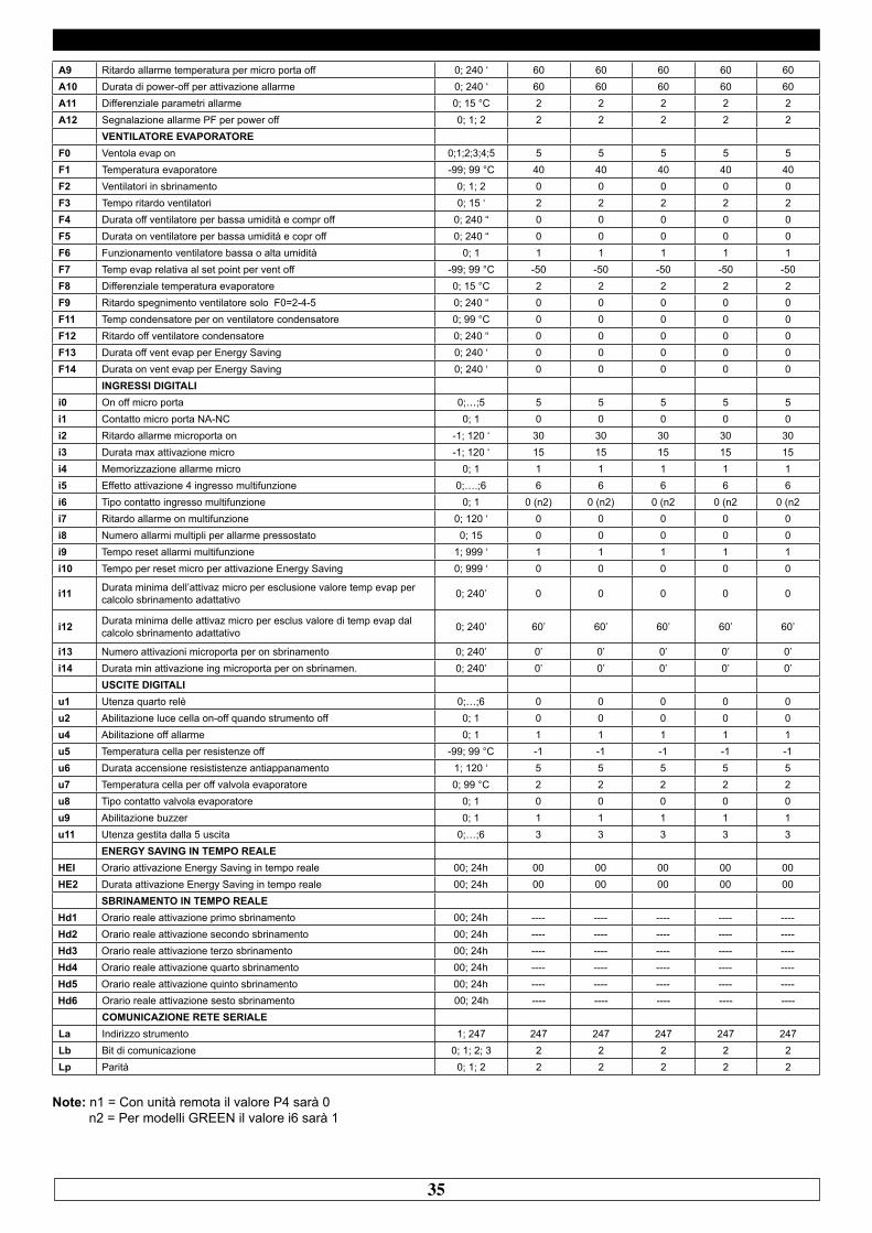
A9 Ritardo allarme temperatura per micro porta off 0; 240 ‘ 60 60 60 60 60A10 Durata di power-off per attivazione allarme 0; 240 ‘ 60 60 60 60 60A11 Differenziale parametri allarme 0; 15 °C 2 2 2 2 2A12 Segnalazione allarme PF per power off 0; 1; 2 2 2 2 2 2
VENTILATORE EVAPORATOREF0 Ventola evap on 0;1;2;3;4;5 5 5 5 5 5F1 Temperatura evaporatore -99; 99 °C 40 40 40 40 40F2 Ventilatori in sbrinamento 0; 1; 2 0 0 0 0 0F3 Tempo ritardo ventilatori 0; 15 ‘ 2 2 2 2 2F4 Durata off ventilatore per bassa umidità e compr off 0; 240 “ 0 0 0 0 0F5 Durata on ventilatore per bassa umidità e copr off 0; 240 “ 0 0 0 0 0F6 Funzionamento ventilatore bassa o alta umidità 0; 1 1 1 1 1 1F7 Temp evap relativa al set point per vent off -99; 99 °C -50 -50 -50 -50 -50F8 Differenziale temperatura evaporatore 0; 15 °C 2 2 2 2 2F9 Ritardo spegnimento ventilatore solo F0=2-4-5 0; 240 “ 0 0 0 0 0F11 Temp condensatore per on ventilatore condensatore 0; 99 °C 0 0 0 0 0F12 Ritardo off ventilatore condensatore 0; 240 “ 0 0 0 0 0F13 Durata off vent evap per Energy Saving 0; 240 ‘ 0 0 0 0 0F14 Durata on vent evap per Energy Saving 0; 240 ‘ 0 0 0 0 0
INGRESSI DIGITALIi0 On off micro porta 0;…;5 5 5 5 5 5i1 Contatto micro porta NA-NC 0; 1 0 0 0 0 0i2 Ritardo allarme microporta on -1; 120 ‘ 30 30 30 30 30i3 Durata max attivazione micro -1; 120 ‘ 15 15 15 15 15i4 Memorizzazione allarme micro 0; 1 1 1 1 1 1i5 Effetto attivazione 4 ingresso multifunzione 0;….;6 6 6 6 6 6i6 Tipo contatto ingresso multifunzione 0; 1 0 (n2) 0 (n2) 0 (n2 0 (n2 0 (n2i7 Ritardo allarme on multifunzione 0; 120 ‘ 0 0 0 0 0i8 Numero allarmi multipli per allarme pressostato 0; 15 0 0 0 0 0i9 Tempo reset allarmi multifunzione 1; 999 ‘ 1 1 1 1 1i10 Tempo per reset micro per attivazione Energy Saving 0; 999 ‘ 0 0 0 0 0
i11 Durata minima dell’attivaz micro per esclusione valore temp evap per calcolo sbrinamento adattativo 0; 240’ 0 0 0 0 0
i12 Durata minima delle attivaz micro per esclus valore di temp evap dal calcolo sbrinamento adattativo 0; 240’ 60’ 60’ 60’ 60’ 60’
i13 Numero attivazioni microporta per on sbrinamento 0; 240’ 0’ 0’ 0’ 0’ 0’i14 Durata min attivazione ing microporta per on sbrinamen. 0; 240’ 0’ 0’ 0’ 0’ 0’
USCITE DIGITALIu1 Utenza quarto relè 0;…;6 0 0 0 0 0u2 Abilitazione luce cella on-off quando strumento off 0; 1 0 0 0 0 0u4 Abilitazione off allarme 0; 1 1 1 1 1 1u5 Temperatura cella per resistenze off -99; 99 °C -1 -1 -1 -1 -1u6 Durata accensione resististenze antiappanamento 1; 120 ‘ 5 5 5 5 5u7 Temperatura cella per off valvola evaporatore 0; 99 °C 2 2 2 2 2u8 Tipo contatto valvola evaporatore 0; 1 0 0 0 0 0u9 Abilitazione buzzer 0; 1 1 1 1 1 1u11 Utenza gestita dalla 5 uscita 0;…;6 3 3 3 3 3
ENERGY SAVING IN TEMPO REALEHEI Orario attivazione Energy Saving in tempo reale 00; 24h 00 00 00 00 00HE2 Durata attivazione Energy Saving in tempo reale 00; 24h 00 00 00 00 00
SBRINAMENTO IN TEMPO REALEHd1 Orario reale attivazione primo sbrinamento 00; 24h ---- ---- ---- ---- ----Hd2 Orario reale attivazione secondo sbrinamento 00; 24h ---- ---- ---- ---- ----Hd3 Orario reale attivazione terzo sbrinamento 00; 24h ---- ---- ---- ---- ----Hd4 Orario reale attivazione quarto sbrinamento 00; 24h ---- ---- ---- ---- ----Hd5 Orario reale attivazione quinto sbrinamento 00; 24h ---- ---- ---- ---- ----Hd6 Orario reale attivazione sesto sbrinamento 00; 24h ---- ---- ---- ---- ----
COMUNICAZIONE RETE SERIALELa Indirizzo strumento 1; 247 247 247 247 247 247Lb Bit di comunicazione 0; 1; 2; 3 2 2 2 2 2Lp Parità 0; 1; 2 2 2 2 2 2
Note: n1 = Con unità remota il valore P4 sarà 0 n2 = Per modelli GREEN il valore i6 sarà 1
36
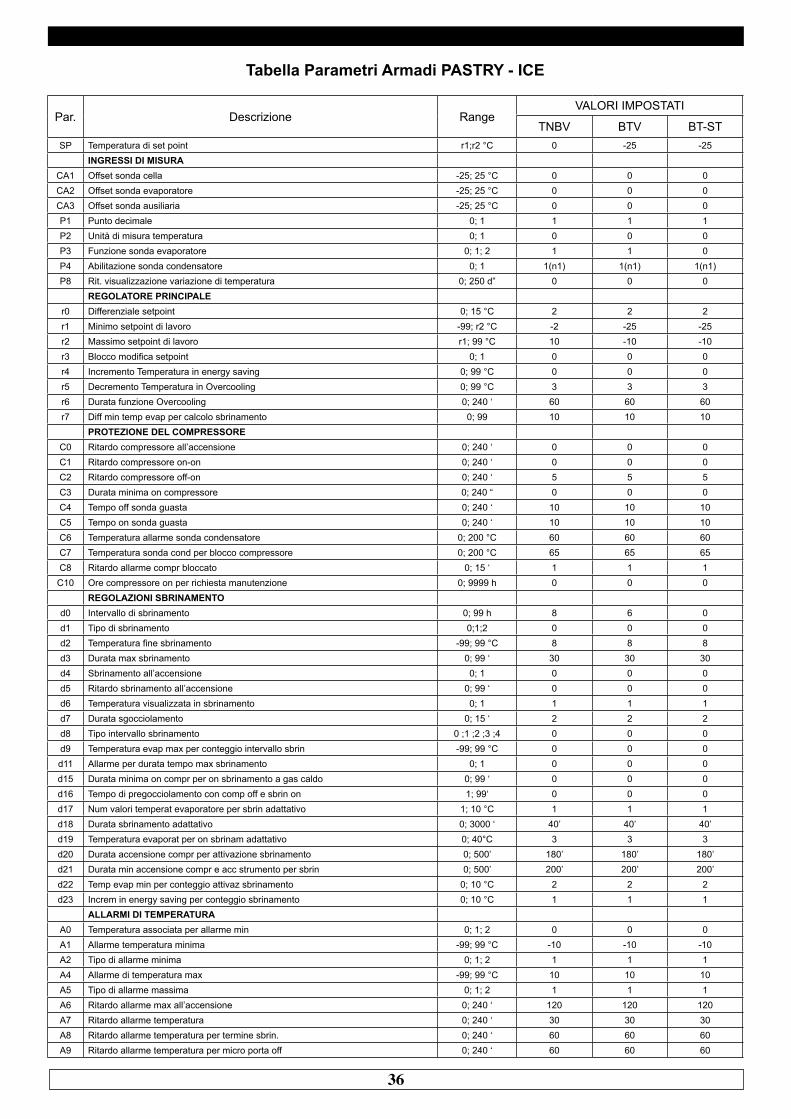
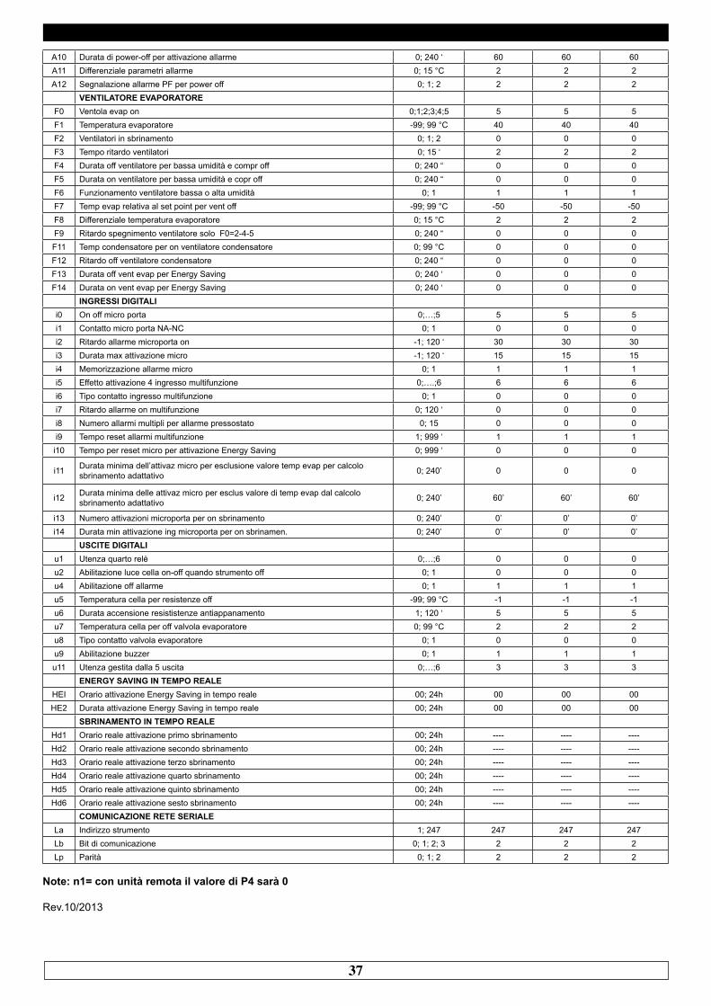
Tabella Parametri Armadi PASTRY - ICE
Par. Descrizione RangeVALORI IMPOSTATI
TNBV BTV BT-STSP Temperatura di set point r1;r2 °C 0 -25 -25
INGRESSI DI MISURACA1 Offset sonda cella -25; 25 °C 0 0 0CA2 Offset sonda evaporatore -25; 25 °C 0 0 0CA3 Offset sonda ausiliaria -25; 25 °C 0 0 0P1 Punto decimale 0; 1 1 1 1P2 Unità di misura temperatura 0; 1 0 0 0P3 Funzione sonda evaporatore 0; 1; 2 1 1 0P4 Abilitazione sonda condensatore 0; 1 1(n1) 1(n1) 1(n1)P8 Rit. visualizzazione variazione di temperatura 0; 250 d” 0 0 0
REGOLATORE PRINCIPALEr0 Differenziale setpoint 0; 15 °C 2 2 2r1 Minimo setpoint di lavoro -99; r2 °C -2 -25 -25r2 Massimo setpoint di lavoro r1; 99 °C 10 -10 -10r3 Blocco modifica setpoint 0; 1 0 0 0r4 Incremento Temperatura in energy saving 0; 99 °C 0 0 0r5 Decremento Temperatura in Overcooling 0; 99 °C 3 3 3r6 Durata funzione Overcooling 0; 240 ‘ 60 60 60r7 Diff min temp evap per calcolo sbrinamento 0; 99 10 10 10
PROTEZIONE DEL COMPRESSOREC0 Ritardo compressore all’accensione 0; 240 ‘ 0 0 0C1 Ritardo compressore on-on 0; 240 ‘ 0 0 0C2 Ritardo compressore off-on 0; 240 ‘ 5 5 5C3 Durata minima on compressore 0; 240 “ 0 0 0C4 Tempo off sonda guasta 0; 240 ‘ 10 10 10C5 Tempo on sonda guasta 0; 240 ‘ 10 10 10C6 Temperatura allarme sonda condensatore 0; 200 °C 60 60 60C7 Temperatura sonda cond per blocco compressore 0; 200 °C 65 65 65C8 Ritardo allarme compr bloccato 0; 15 ‘ 1 1 1C10 Ore compressore on per richiesta manutenzione 0; 9999 h 0 0 0
REGOLAZIONI SBRINAMENTOd0 Intervallo di sbrinamento 0; 99 h 8 6 0d1 Tipo di sbrinamento 0;1;2 0 0 0d2 Temperatura fine sbrinamento -99; 99 °C 8 8 8d3 Durata max sbrinamento 0; 99 ‘ 30 30 30d4 Sbrinamento all’accensione 0; 1 0 0 0d5 Ritardo sbrinamento all’accensione 0; 99 ‘ 0 0 0d6 Temperatura visualizzata in sbrinamento 0; 1 1 1 1d7 Durata sgocciolamento 0; 15 ‘ 2 2 2d8 Tipo intervallo sbrinamento 0 ;1 ;2 ;3 ;4 0 0 0d9 Temperatura evap max per conteggio intervallo sbrin -99; 99 °C 0 0 0d11 Allarme per durata tempo max sbrinamento 0; 1 0 0 0d15 Durata minima on compr per on sbrinamento a gas caldo 0; 99 ‘ 0 0 0d16 Tempo di pregocciolamento con comp off e sbrin on 1; 99‘ 0 0 0d17 Num valori temperat evaporatore per sbrin adattativo 1; 10 °C 1 1 1d18 Durata sbrinamento adattativo 0; 3000 ‘ 40’ 40’ 40’d19 Temperatura evaporat per on sbrinam adattativo 0; 40°C 3 3 3d20 Durata accensione compr per attivazione sbrinamento 0; 500’ 180’ 180’ 180’d21 Durata min accensione compr e acc strumento per sbrin 0; 500’ 200’ 200’ 200’d22 Temp evap min per conteggio attivaz sbrinamento 0; 10 °C 2 2 2d23 Increm in energy saving per conteggio sbrinamento 0; 10 °C 1 1 1
ALLARMI DI TEMPERATURAA0 Temperatura associata per allarme min 0; 1; 2 0 0 0A1 Allarme temperatura minima -99; 99 °C -10 -10 -10A2 Tipo di allarme minima 0; 1; 2 1 1 1A4 Allarme di temperatura max -99; 99 °C 10 10 10A5 Tipo di allarme massima 0; 1; 2 1 1 1A6 Ritardo allarme max all’accensione 0; 240 ‘ 120 120 120A7 Ritardo allarme temperatura 0; 240 ‘ 30 30 30A8 Ritardo allarme temperatura per termine sbrin. 0; 240 ‘ 60 60 60A9 Ritardo allarme temperatura per micro porta off 0; 240 ‘ 60 60 60
37
A10 Durata di power-off per attivazione allarme 0; 240 ‘ 60 60 60A11 Differenziale parametri allarme 0; 15 °C 2 2 2A12 Segnalazione allarme PF per power off 0; 1; 2 2 2 2
VENTILATORE EVAPORATOREF0 Ventola evap on 0;1;2;3;4;5 5 5 5F1 Temperatura evaporatore -99; 99 °C 40 40 40F2 Ventilatori in sbrinamento 0; 1; 2 0 0 0F3 Tempo ritardo ventilatori 0; 15 ‘ 2 2 2F4 Durata off ventilatore per bassa umidità e compr off 0; 240 “ 0 0 0F5 Durata on ventilatore per bassa umidità e copr off 0; 240 “ 0 0 0F6 Funzionamento ventilatore bassa o alta umidità 0; 1 1 1 1F7 Temp evap relativa al set point per vent off -99; 99 °C -50 -50 -50F8 Differenziale temperatura evaporatore 0; 15 °C 2 2 2F9 Ritardo spegnimento ventilatore solo F0=2-4-5 0; 240 “ 0 0 0F11 Temp condensatore per on ventilatore condensatore 0; 99 °C 0 0 0F12 Ritardo off ventilatore condensatore 0; 240 “ 0 0 0F13 Durata off vent evap per Energy Saving 0; 240 ‘ 0 0 0F14 Durata on vent evap per Energy Saving 0; 240 ‘ 0 0 0
INGRESSI DIGITALIi0 On off micro porta 0;…;5 5 5 5i1 Contatto micro porta NA-NC 0; 1 0 0 0i2 Ritardo allarme microporta on -1; 120 ‘ 30 30 30i3 Durata max attivazione micro -1; 120 ‘ 15 15 15i4 Memorizzazione allarme micro 0; 1 1 1 1i5 Effetto attivazione 4 ingresso multifunzione 0;….;6 6 6 6i6 Tipo contatto ingresso multifunzione 0; 1 0 0 0i7 Ritardo allarme on multifunzione 0; 120 ‘ 0 0 0i8 Numero allarmi multipli per allarme pressostato 0; 15 0 0 0i9 Tempo reset allarmi multifunzione 1; 999 ‘ 1 1 1i10 Tempo per reset micro per attivazione Energy Saving 0; 999 ‘ 0 0 0
i11 Durata minima dell’attivaz micro per esclusione valore temp evap per calcolo sbrinamento adattativo 0; 240’ 0 0 0
i12 Durata minima delle attivaz micro per esclus valore di temp evap dal calcolo sbrinamento adattativo 0; 240’ 60’ 60’ 60’
i13 Numero attivazioni microporta per on sbrinamento 0; 240’ 0’ 0’ 0’i14 Durata min attivazione ing microporta per on sbrinamen. 0; 240’ 0’ 0’ 0’
USCITE DIGITALIu1 Utenza quarto relè 0;…;6 0 0 0u2 Abilitazione luce cella on-off quando strumento off 0; 1 0 0 0u4 Abilitazione off allarme 0; 1 1 1 1u5 Temperatura cella per resistenze off -99; 99 °C -1 -1 -1u6 Durata accensione resististenze antiappanamento 1; 120 ‘ 5 5 5u7 Temperatura cella per off valvola evaporatore 0; 99 °C 2 2 2u8 Tipo contatto valvola evaporatore 0; 1 0 0 0u9 Abilitazione buzzer 0; 1 1 1 1u11 Utenza gestita dalla 5 uscita 0;…;6 3 3 3
ENERGY SAVING IN TEMPO REALEHEI Orario attivazione Energy Saving in tempo reale 00; 24h 00 00 00HE2 Durata attivazione Energy Saving in tempo reale 00; 24h 00 00 00
SBRINAMENTO IN TEMPO REALEHd1 Orario reale attivazione primo sbrinamento 00; 24h ---- ---- ----Hd2 Orario reale attivazione secondo sbrinamento 00; 24h ---- ---- ----Hd3 Orario reale attivazione terzo sbrinamento 00; 24h ---- ---- ----Hd4 Orario reale attivazione quarto sbrinamento 00; 24h ---- ---- ----Hd5 Orario reale attivazione quinto sbrinamento 00; 24h ---- ---- ----Hd6 Orario reale attivazione sesto sbrinamento 00; 24h ---- ---- ----
COMUNICAZIONE RETE SERIALELa Indirizzo strumento 1; 247 247 247 247Lb Bit di comunicazione 0; 1; 2; 3 2 2 2Lp Parità 0; 1; 2 2 2 2
Note: n1= con unità remota il valore di P4 sarà 0
Rev.10/2013
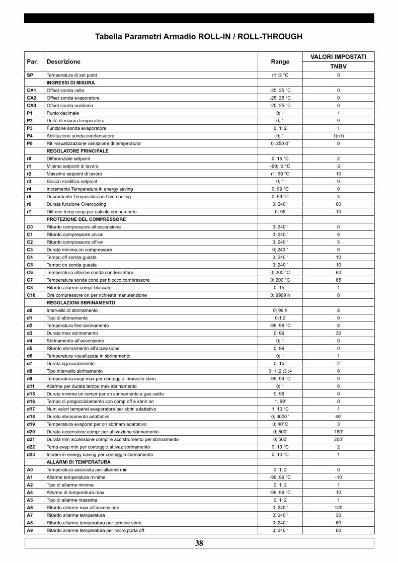
38
Tabella Parametri Armadio ROLL-IN / ROLL-THROUGH
Par. Descrizione RangeVALORI IMPOSTATI
TNBVSP Temperatura di set point r1;r2 °C 0
INGRESSI DI MISURACA1 Offset sonda cella -25; 25 °C 0CA2 Offset sonda evaporatore -25; 25 °C 0CA3 Offset sonda ausiliaria -25; 25 °C 0P1 Punto decimale 0; 1 1P2 Unità di misura temperatura 0; 1 0P3 Funzione sonda evaporatore 0; 1; 2 1P4 Abilitazione sonda condensatore 0; 1 1(n1)P8 Rit. visualizzazione variazione di temperatura 0; 250 d” 0
REGOLATORE PRINCIPALEr0 Differenziale setpoint 0; 15 °C 2r1 Minimo setpoint di lavoro -99; r2 °C -2r2 Massimo setpoint di lavoro r1; 99 °C 10r3 Blocco modifica setpoint 0; 1 0r4 Incremento Temperatura in energy saving 0; 99 °C 0r5 Decremento Temperatura in Overcooling 0; 99 °C 3r6 Durata funzione Overcooling 0; 240 ‘ 60r7 Diff min temp evap per calcolo sbrinamento 0; 99 10
PROTEZIONE DEL COMPRESSOREC0 Ritardo compressore all’accensione 0; 240 ‘ 0C1 Ritardo compressore on-on 0; 240 ‘ 0C2 Ritardo compressore off-on 0; 240 ‘ 5C3 Durata minima on compressore 0; 240 “ 0C4 Tempo off sonda guasta 0; 240 ‘ 10C5 Tempo on sonda guasta 0; 240 ‘ 10C6 Temperatura allarme sonda condensatore 0; 200 °C 60C7 Temperatura sonda cond per blocco compressore 0; 200 °C 65C8 Ritardo allarme compr bloccato 0; 15 ‘ 1C10 Ore compressore on per richiesta manutenzione 0; 9999 h 0
REGOLAZIONI SBRINAMENTOd0 Intervallo di sbrinamento 0; 99 h 8d1 Tipo di sbrinamento 0;1;2 0d2 Temperatura fine sbrinamento -99; 99 °C 8d3 Durata max sbrinamento 0; 99 ‘ 30d4 Sbrinamento all’accensione 0; 1 0d5 Ritardo sbrinamento all’accensione 0; 99 ‘ 0d6 Temperatura visualizzata in sbrinamento 0; 1 1d7 Durata sgocciolamento 0; 15 ‘ 2d8 Tipo intervallo sbrinamento 0 ;1 ;2 ;3 ;4 0d9 Temperatura evap max per conteggio intervallo sbrin -99; 99 °C 0d11 Allarme per durata tempo max sbrinamento 0; 1 0d15 Durata minima on compr per on sbrinamento a gas caldo 0; 99 ‘ 0d16 Tempo di pregocciolamento con comp off e sbrin on 1; 99‘ 0d17 Num valori temperat evaporatore per sbrin adattativo 1; 10 °C 1d18 Durata sbrinamento adattativo 0; 3000 ‘ 40’d19 Temperatura evaporat per on sbrinam adattativo 0; 40°C 3d20 Durata accensione compr per attivazione sbrinamento 0; 500’ 180’d21 Durata min accensione compr e acc strumento per sbrinamento 0; 500’ 200’d22 Temp evap min per conteggio attivaz sbrinamento 0; 10 °C 2d23 Increm in energy saving per conteggio sbrinamento 0; 10 °C 1
ALLARMI DI TEMPERATURAA0 Temperatura associata per allarme min 0; 1; 2 0A1 Allarme temperatura minima -99; 99 °C -10A2 Tipo di allarme minima 0; 1; 2 1A4 Allarme di temperatura max -99; 99 °C 10A5 Tipo di allarme massima 0; 1; 2 1A6 Ritardo allarme max all’accensione 0; 240 ‘ 120A7 Ritardo allarme temperatura 0; 240 ‘ 30A8 Ritardo allarme temperatura per termine sbrin. 0; 240 ‘ 60A9 Ritardo allarme temperatura per micro porta off 0; 240 ‘ 60
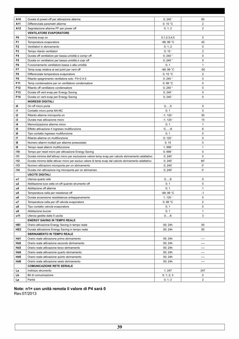
39
A10 Durata di power-off per attivazione allarme 0; 240 ‘ 60A11 Differenziale parametri allarme 0; 15 °C 2A12 Segnalazione allarme PF per power off 0; 1; 2 2
VENTILATORE EVAPORATOREF0 Ventola evap on 0;1;2;3;4;5 5F1 Temperatura evaporatore -99; 99 °C 40F2 Ventilatori in sbrinamento 0; 1; 2 0F3 Tempo ritardo ventilatori 0; 15 ‘ 2F4 Durata off ventilatore per bassa umidità e compr off 0; 240 “ 0F5 Durata on ventilatore per bassa umidità e copr off 0; 240 “ 0F6 Funzionamento ventilatore bassa o alta umidità 0; 1 1F7 Temp evap relativa al set point per vent off -99; 99 °C -50F8 Differenziale temperatura evaporatore 0; 15 °C 2F9 Ritardo spegnimento ventilatore solo F0=2-4-5 0; 240 “ 0F11 Temp condensatore per on ventilatore condensatore 0; 99 °C 0F12 Ritardo off ventilatore condensatore 0; 240 “ 0F13 Durata off vent evap per Energy Saving 0; 240 ‘ 0F14 Durata on vent evap per Energy Saving 0; 240 ‘ 0
INGRESSI DIGITALIi0 On off micro porta 0;…;5 5i1 Contatto micro porta NA-NC 0; 1 0i2 Ritardo allarme microporta on -1; 120 ‘ 30i3 Durata max attivazione micro -1; 120 ‘ 15i4 Memorizzazione allarme micro 0; 1 1i5 Effetto attivazione 4 ingresso multifunzione 0;….;6 6i6 Tipo contatto ingresso multifunzione 0; 1 0i7 Ritardo allarme on multifunzione 0; 120 ‘ 0i8 Numero allarmi multipli per allarme pressostato 0; 15 0i9 Tempo reset allarmi multifunzione 1; 999 ‘ 1i10 Tempo per reset micro per attivazione Energy Saving 0; 999 ‘ 0i11 Durata minima dell’attivaz micro per esclusione valore temp evap per calcolo sbrinamento adattativo 0; 240’ 0i12 Durata minima delle attivaz micro per esclus valore di temp evap dal calcolo sbrinamento adattativo 0; 240’ 60’i13 Numero attivazioni microporta per on sbrinamento 0; 240’ 0’i14 Durata min attivazione ing microporta per on sbrinamen. 0; 240’ 0’
USCITE DIGITALIu1 Utenza quarto relè 0;…;6 0u2 Abilitazione luce cella on-off quando strumento off 0; 1 0u4 Abilitazione off allarme 0; 1 1u5 Temperatura cella per resistenze off -99; 99 °C -1u6 Durata accensione resististenze antiappanamento 1; 120 ‘ 5u7 Temperatura cella per off valvola evaporatore 0; 99 °C 2u8 Tipo contatto valvola evaporatore 0; 1 0u9 Abilitazione buzzer 0; 1 1u11 Utenza gestita dalla 5 uscita 0;…;6 3
ENERGY SAVING IN TEMPO REALEHEI Orario attivazione Energy Saving in tempo reale 00; 24h 00HE2 Durata attivazione Energy Saving in tempo reale 00; 24h 00
SBRINAMENTO IN TEMPO REALEHd1 Orario reale attivazione primo sbrinamento 00; 24h ----Hd2 Orario reale attivazione secondo sbrinamento 00; 24h ----Hd3 Orario reale attivazione terzo sbrinamento 00; 24h ----Hd4 Orario reale attivazione quarto sbrinamento 00; 24h ----Hd5 Orario reale attivazione quinto sbrinamento 00; 24h ----Hd6 Orario reale attivazione sesto sbrinamento 00; 24h ----
COMUNICAZIONE RETE SERIALELa Indirizzo strumento 1; 247 247Lb Bit di comunicazione 0; 1; 2; 3 2Lp Parità 0; 1; 2 2
Note: n1= con unità remota il valore di P4 sarà 0Rev.07/2013
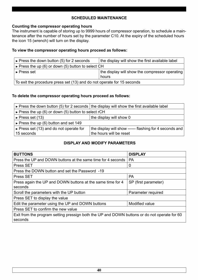
40
SCHEDULED MAINTENANCE
Counting the compressor operating hoursThe instrument is capable of storing up to 9999 hours of compressor operation, to schedule a main-tenance after the number of hours set by the parameter C10. At the expiry of the scheduled hoursthe icon 15 (wrench) will turn on the display.
To view the compressor operating hours proceed as follows:
► Press the down button (5) for 2 seconds the display will show the first available label► Press the up (6) or down (5) button to select CH► Press set the display will show the compressor operating
hoursTo exit the procedure press set (13) and do not operate for 15 seconds
To delete the compressor operating hours proceed as follows:
► Press the down button (5) for 2 seconds the display will show the first available label► Press the up (6) or down (5) button to select rCH► Press set (13) the display will show 0► Press the up (6) button and set 149► Press set (13) and do not operate for15 seconds
the display will show ------ flashing for 4 seconds and the hours will be reset
DISPLAY AND MODIFY PARAMETERS
BUTTONS DISPLAYPress the UP and DOWN buttons at the same time for 4 seconds PAPress SET 0Press the DOWN button and set the Password -19Press SET PAPress again the UP and DOWN buttons at the same time for 4 seconds
SP (first parameter)
Scroll the parameters with the UP button Parameter requiredPress SET to display the valueEdit the parameter using the UP and DOWN buttons Modified valuePress SET to confirm the new valueExit from the program setting pressign both the UP and DOWN buttons or do not operate for 60 seconds
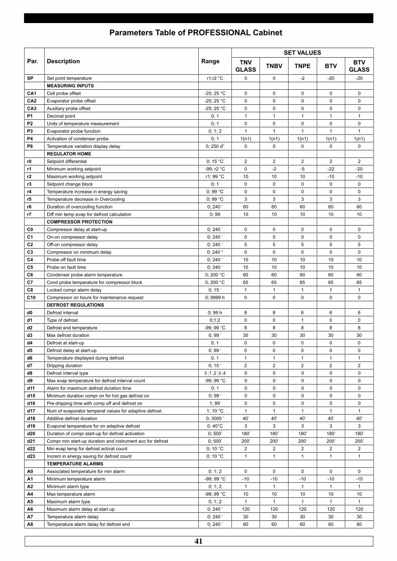
41
Parameters Table of PROFESSIONAL Cabinet
Par. Description RangeSET VALUES
TNVGLASS TNBV TNPE BTV BTV
GLASSSP Set point temperature r1;r2 °C 0 0 -2 -20 -20
MEASURING INPUTSCA1 Cell probe offset -25; 25 °C 0 0 0 0 0CA2 Evaporator probe offset -25; 25 °C 0 0 0 0 0CA3 Auxiliary probe offset -25; 25 °C 0 0 0 0 0P1 Decimal point 0; 1 1 1 1 1 1P2 Units of temperature measurement 0; 1 0 0 0 0 0P3 Evaporator probe function 0; 1; 2 1 1 1 1 1P4 Activation of condenser probe 0; 1 1(n1) 1(n1) 1(n1) 1(n1) 1(n1)P8 Temperature variation display delay 0; 250 d” 0 0 0 0 0
REGULATOR HOMEr0 Setpoint differential 0; 15 °C 2 2 2 2 2r1 Minimum working setpoint -99; r2 °C 0 -2 -5 -22 -20r2 Maximum working setpoint r1; 99 °C 10 10 10 -10 -10r3 Setpoint change block 0; 1 0 0 0 0 0r4 Temperature increase in energy saving 0; 99 °C 0 0 0 0 0r5 Temperature decrease in Overcooling 0; 99 °C 3 3 3 3 3r6 Duration of overcooling function 0; 240 ‘ 60 60 60 60 60r7 Diff min temp evap for defrost calculation 0; 99 10 10 10 10 10
COMPRESSOR PROTECTIONC0 Compressor delay at start-up 0; 240 ‘ 0 0 0 0 0C1 On-on compressor delay 0; 240 ‘ 0 0 0 0 0C2 Off-on compressor delay 0; 240 ‘ 5 5 5 5 5C3 Compressor on minimum delay 0; 240 “ 0 0 0 0 0C4 Probe off fault time 0; 240 ‘ 10 10 10 10 10C5 Probe on fault time 0; 240 ‘ 10 10 10 10 10C6 Condenser probe alarm temperature 0; 200 °C 60 60 60 60 60C7 Cond probe temperature for compressor block 0; 200 °C 65 65 65 65 65C8 Locked compr alarm delay 0; 15 ‘ 1 1 1 1 1C10 Compressor on hours for maintenance request 0; 9999 h 0 0 0 0 0
DEFROST REGULATIONSd0 Defrost interval 0; 99 h 8 8 6 6 6d1 Type of defrost 0;1;2 0 0 1 0 0d2 Defrost end temperature -99; 99 °C 8 8 8 8 8d3 Max defrost duration 0; 99 ‘ 30 30 30 30 30d4 Defrost at start-up 0; 1 0 0 0 0 0d5 Defrost delay at start-up 0; 99 ‘ 0 0 0 0 0d6 Temperature displayed during defrost 0; 1 1 1 1 1 1d7 Dripping duration 0; 15 ‘ 2 2 2 2 2d8 Defrost interval type 0 ;1 ;2 ;3 ;4 0 0 0 0 0d9 Max evap temperature for defrost interval count -99; 99 °C 0 0 0 0 0d11 Alarm for maximum defrost duration time 0; 1 0 0 0 0 0d15 Minimum duration compr on for hot gas defrost on 0; 99 ‘ 0 0 0 0 0d16 Pre-dripping time with comp off and defrost on 1; 99‘ 0 0 0 0 0d17 Num of evaporator temperat values for adaptive defrost 1; 10 °C 1 1 1 1 1d18 Additive defrost duration 0; 3000 ‘ 40’ 40’ 40’ 40’ 40’d19 Evaporat temperature for on adaptive defrost 0; 40°C 3 3 3 3 3d20 Duration of compr start-up for defrost activation 0; 500’ 180’ 180’ 180’ 180’ 180’d21 Compr min start-up duration and instrument acc for defrost 0; 500’ 200’ 200’ 200’ 200’ 200’d22 Min evap temp for defrost activat count 0; 10 °C 2 2 2 2 2d23 Increm in energy saving for defrost count 0; 10 °C 1 1 1 1 1
TEMPERATURE ALARMSA0 Associated temperature for min alarm 0; 1; 2 0 0 0 0 0A1 Minimum temperature alarm -99; 99 °C -10 -10 -10 -10 -10A2 Minimum alarm type 0; 1; 2 1 1 1 1 1A4 Max temperature alarm -99; 99 °C 10 10 10 10 10A5 Maximum alarm type 0; 1; 2 1 1 1 1 1A6 Maximum alarm delay at start up 0; 240 ‘ 120 120 120 120 120A7 Temperature alarm delay 0; 240 ‘ 30 30 30 30 30A8 Temperature alarm delay for defrost end 0; 240 ‘ 60 60 60 60 60
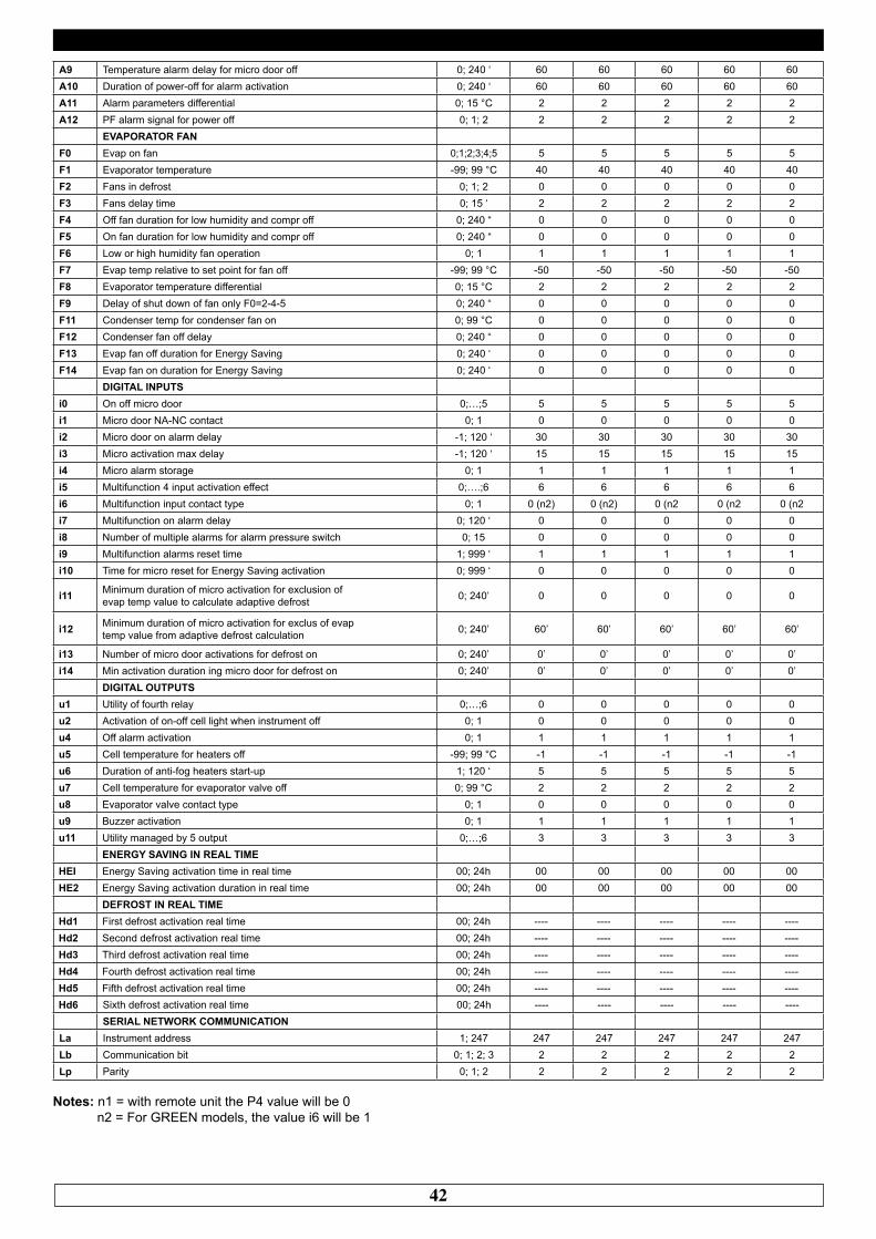
42
A9 Temperature alarm delay for micro door off 0; 240 ‘ 60 60 60 60 60A10 Duration of power-off for alarm activation 0; 240 ‘ 60 60 60 60 60A11 Alarm parameters differential 0; 15 °C 2 2 2 2 2A12 PF alarm signal for power off 0; 1; 2 2 2 2 2 2
EVAPORATOR FANF0 Evap on fan 0;1;2;3;4;5 5 5 5 5 5F1 Evaporator temperature -99; 99 °C 40 40 40 40 40F2 Fans in defrost 0; 1; 2 0 0 0 0 0F3 Fans delay time 0; 15 ‘ 2 2 2 2 2F4 Off fan duration for low humidity and compr off 0; 240 “ 0 0 0 0 0F5 On fan duration for low humidity and compr off 0; 240 “ 0 0 0 0 0F6 Low or high humidity fan operation 0; 1 1 1 1 1 1F7 Evap temp relative to set point for fan off -99; 99 °C -50 -50 -50 -50 -50F8 Evaporator temperature differential 0; 15 °C 2 2 2 2 2F9 Delay of shut down of fan only F0=2-4-5 0; 240 “ 0 0 0 0 0F11 Condenser temp for condenser fan on 0; 99 °C 0 0 0 0 0F12 Condenser fan off delay 0; 240 “ 0 0 0 0 0F13 Evap fan off duration for Energy Saving 0; 240 ‘ 0 0 0 0 0F14 Evap fan on duration for Energy Saving 0; 240 ‘ 0 0 0 0 0
DIGITAL INPUTSi0 On off micro door 0;…;5 5 5 5 5 5i1 Micro door NA-NC contact 0; 1 0 0 0 0 0i2 Micro door on alarm delay -1; 120 ‘ 30 30 30 30 30i3 Micro activation max delay -1; 120 ‘ 15 15 15 15 15i4 Micro alarm storage 0; 1 1 1 1 1 1i5 Multifunction 4 input activation effect 0;….;6 6 6 6 6 6i6 Multifunction input contact type 0; 1 0 (n2) 0 (n2) 0 (n2 0 (n2 0 (n2i7 Multifunction on alarm delay 0; 120 ‘ 0 0 0 0 0i8 Number of multiple alarms for alarm pressure switch 0; 15 0 0 0 0 0i9 Multifunction alarms reset time 1; 999 ‘ 1 1 1 1 1i10 Time for micro reset for Energy Saving activation 0; 999 ‘ 0 0 0 0 0
i11 Minimum duration of micro activation for exclusion ofevap temp value to calculate adaptive defrost 0; 240’ 0 0 0 0 0
i12 Minimum duration of micro activation for exclus of evaptemp value from adaptive defrost calculation 0; 240’ 60’ 60’ 60’ 60’ 60’
i13 Number of micro door activations for defrost on 0; 240’ 0’ 0’ 0’ 0’ 0’i14 Min activation duration ing micro door for defrost on 0; 240’ 0’ 0’ 0’ 0’ 0’
DIGITAL OUTPUTSu1 Utility of fourth relay 0;…;6 0 0 0 0 0u2 Activation of on-off cell light when instrument off 0; 1 0 0 0 0 0u4 Off alarm activation 0; 1 1 1 1 1 1u5 Cell temperature for heaters off -99; 99 °C -1 -1 -1 -1 -1u6 Duration of anti-fog heaters start-up 1; 120 ‘ 5 5 5 5 5u7 Cell temperature for evaporator valve off 0; 99 °C 2 2 2 2 2u8 Evaporator valve contact type 0; 1 0 0 0 0 0u9 Buzzer activation 0; 1 1 1 1 1 1u11 Utility managed by 5 output 0;…;6 3 3 3 3 3
ENERGY SAVING IN REAL TIMEHEI Energy Saving activation time in real time 00; 24h 00 00 00 00 00HE2 Energy Saving activation duration in real time 00; 24h 00 00 00 00 00
DEFROST IN REAL TIMEHd1 First defrost activation real time 00; 24h ---- ---- ---- ---- ----Hd2 Second defrost activation real time 00; 24h ---- ---- ---- ---- ----Hd3 Third defrost activation real time 00; 24h ---- ---- ---- ---- ----Hd4 Fourth defrost activation real time 00; 24h ---- ---- ---- ---- ----Hd5 Fifth defrost activation real time 00; 24h ---- ---- ---- ---- ----Hd6 Sixth defrost activation real time 00; 24h ---- ---- ---- ---- ----
SERIAL NETWORK COMMUNICATIONLa Instrument address 1; 247 247 247 247 247 247Lb Communication bit 0; 1; 2; 3 2 2 2 2 2Lp Parity 0; 1; 2 2 2 2 2 2
Notes: n1 = with remote unit the P4 value will be 0 n2 = For GREEN models, the value i6 will be 1
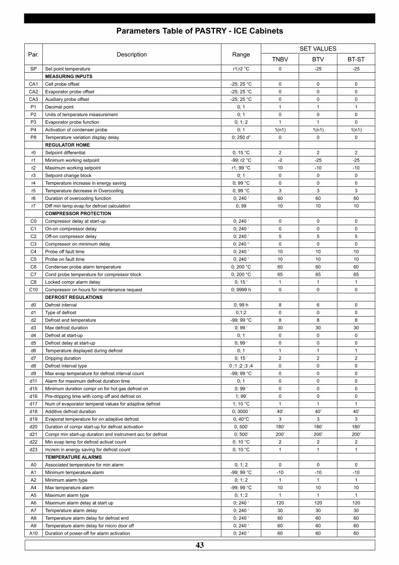
43
Parameters Table of PASTRY - ICE Cabinets
Par. Description RangeSET VALUES
TNBV BTV BT-STSP Set point temperature r1;r2 °C 0 -25 -25
MEASURING INPUTSCA1 Cell probe offset -25; 25 °C 0 0 0CA2 Evaporator probe offset -25; 25 °C 0 0 0CA3 Auxiliary probe offset -25; 25 °C 0 0 0P1 Decimal point 0; 1 1 1 1P2 Units of temperature measurement 0; 1 0 0 0P3 Evaporator probe function 0; 1; 2 1 1 0P4 Activation of condenser probe 0; 1 1(n1) 1(n1) 1(n1)P8 Temperature variation display delay 0; 250 d” 0 0 0
REGULATOR HOMEr0 Setpoint differential 0; 15 °C 2 2 2r1 Minimum working setpoint -99; r2 °C -2 -25 -25r2 Maximum working setpoint r1; 99 °C 10 -10 -10r3 Setpoint change block 0; 1 0 0 0r4 Temperature increase in energy saving 0; 99 °C 0 0 0r5 Temperature decrease in Overcooling 0; 99 °C 3 3 3r6 Duration of overcooling function 0; 240 ‘ 60 60 60r7 Diff min temp evap for defrost calculation 0; 99 10 10 10
COMPRESSOR PROTECTIONC0 Compressor delay at start-up 0; 240 ‘ 0 0 0C1 On-on compressor delay 0; 240 ‘ 0 0 0C2 Off-on compressor delay 0; 240 ‘ 5 5 5C3 Compressor on minimum delay 0; 240 “ 0 0 0C4 Probe off fault time 0; 240 ‘ 10 10 10C5 Probe on fault time 0; 240 ‘ 10 10 10C6 Condenser probe alarm temperature 0; 200 °C 60 60 60C7 Cond probe temperature for compressor block 0; 200 °C 65 65 65C8 Locked compr alarm delay 0; 15 ‘ 1 1 1
C10 Compressor on hours for maintenance request 0; 9999 h 0 0 0DEFROST REGULATIONS
d0 Defrost interval 0; 99 h 8 6 0d1 Type of defrost 0;1;2 0 0 0d2 Defrost end temperature -99; 99 °C 8 8 8d3 Max defrost duration 0; 99 ‘ 30 30 30d4 Defrost at start-up 0; 1 0 0 0d5 Defrost delay at start-up 0; 99 ‘ 0 0 0d6 Temperature displayed during defrost 0; 1 1 1 1d7 Dripping duration 0; 15 ‘ 2 2 2d8 Defrost interval type 0 ;1 ;2 ;3 ;4 0 0 0d9 Max evap temperature for defrost interval count -99; 99 °C 0 0 0d11 Alarm for maximum defrost duration time 0; 1 0 0 0d15 Minimum duration compr on for hot gas defrost on 0; 99 ‘ 0 0 0d16 Pre-dripping time with comp off and defrost on 1; 99‘ 0 0 0d17 Num of evaporator temperat values for adaptive defrost 1; 10 °C 1 1 1d18 Additive defrost duration 0; 3000 ‘ 40’ 40’ 40’d19 Evaporat temperature for on adaptive defrost 0; 40°C 3 3 3d20 Duration of compr start-up for defrost activation 0; 500’ 180’ 180’ 180’d21 Compr min start-up duration and instrument acc for defrost 0; 500’ 200’ 200’ 200’d22 Min evap temp for defrost activat count 0; 10 °C 2 2 2d23 Increm in energy saving for defrost count 0; 10 °C 1 1 1
TEMPERATURE ALARMSA0 Associated temperature for min alarm 0; 1; 2 0 0 0A1 Minimum temperature alarm -99; 99 °C -10 -10 -10A2 Minimum alarm type 0; 1; 2 1 1 1A4 Max temperature alarm -99; 99 °C 10 10 10A5 Maximum alarm type 0; 1; 2 1 1 1A6 Maximum alarm delay at start up 0; 240 ‘ 120 120 120A7 Temperature alarm delay 0; 240 ‘ 30 30 30A8 Temperature alarm delay for defrost end 0; 240 ‘ 60 60 60A9 Temperature alarm delay for micro door off 0; 240 ‘ 60 60 60A10 Duration of power-off for alarm activation 0; 240 ‘ 60 60 60

44
A11 Alarm parameters differential 0; 15 °C 2 2 2A12 PF alarm signal for power off 0; 1; 2 2 2 2
EVAPORATOR FANF0 Evap on fan 0;1;2;3;4;5 5 5 5F1 Evaporator temperature -99; 99 °C 40 40 40F2 Fans in defrost 0; 1; 2 0 0 0F3 Fans delay time 0; 15 ‘ 2 2 2F4 Off fan duration for low humidity and compr off 0; 240 “ 0 0 0F5 On fan duration for low humidity and compr off 0; 240 “ 0 0 0F6 Low or high humidity fan operation 0; 1 1 1 1F7 Evap temp relative to set point for fan off -99; 99 °C -50 -50 -50F8 Evaporator temperature differential 0; 15 °C 2 2 2F9 Delay of shut down of fan only F0=2-4-5 0; 240 “ 0 0 0F11 Condenser temp for condenser fan on 0; 99 °C 0 0 0F12 Condenser fan off delay 0; 240 “ 0 0 0F13 Evap fan off duration for Energy Saving 0; 240 ‘ 0 0 0F14 Evap fan on duration for Energy Saving 0; 240 ‘ 0 0 0
DIGITAL INPUTSi0 On off micro door 0;…;5 5 5 5i1 Micro door NA-NC contact 0; 1 0 0 0i2 Micro door on alarm delay -1; 120 ‘ 30 30 30i3 Micro activation max delay -1; 120 ‘ 15 15 15i4 Micro alarm storage 0; 1 1 1 1i5 Multifunction 4 input activation effect 0;….;6 6 6 6i6 Multifunction input contact type 0; 1 0 0 0i7 Multifunction on alarm delay 0; 120 ‘ 0 0 0i8 Number of multiple alarms for alarm pressure switch 0; 15 0 0 0i9 Multifunction alarms reset time 1; 999 ‘ 1 1 1
i10 Time for micro reset for Energy Saving activation 0; 999 ‘ 0 0 0
i11 Minimum duration of micro activation for exclusion ofevap temp value to calculate adaptive defrost 0; 240’ 0 0 0
i12 Minimum duration of micro activation for exclus of evaptemp value from adaptive defrost calculation 0; 240’ 60’ 60’ 60’
i13 Number of micro door activations for defrost on 0; 240’ 0’ 0’ 0’i14 Min activation duration ing micro door for defrost on 0; 240’ 0’ 0’ 0’
DIGITAL OUTPUTSu1 Utility of fourth relay 0;…;6 0 0 0u2 Activation of on-off cell light when instrument off 0; 1 0 0 0u4 Off alarm activation 0; 1 1 1 1u5 Cell temperature for heaters off -99; 99 °C -1 -1 -1u6 Duration of anti-fog heaters start-up 1; 120 ‘ 5 5 5u7 Cell temperature for evaporator valve off 0; 99 °C 2 2 2u8 Evaporator valve contact type 0; 1 0 0 0u9 Buzzer activation 0; 1 1 1 1u11 Utility managed by 5 output 0;…;6 3 3 3
ENERGY SAVING IN REAL TIMEHEI Energy Saving activation time in real time 00; 24h 00 00 00HE2 Energy Saving activation duration in real time 00; 24h 00 00 00
DEFROST IN REAL TIMEHd1 First defrost activation real time 00; 24h ---- ---- ----Hd2 Second defrost activation real time 00; 24h ---- ---- ----Hd3 Third defrost activation real time 00; 24h ---- ---- ----Hd4 Fourth defrost activation real time 00; 24h ---- ---- ----Hd5 Fifth defrost activation real time 00; 24h ---- ---- ----Hd6 Sixth defrost activation real time 00; 24h ---- ---- ----
SERIAL NETWORK COMMUNICATIONLa Instrument address 1; 247 247 247 247Lb Communication bit 0; 1; 2; 3 2 2 2Lp Parity 0; 1; 2 2 2 2
Notes: n1= with remote unit the P4 value will be 0
Rev.10/2013
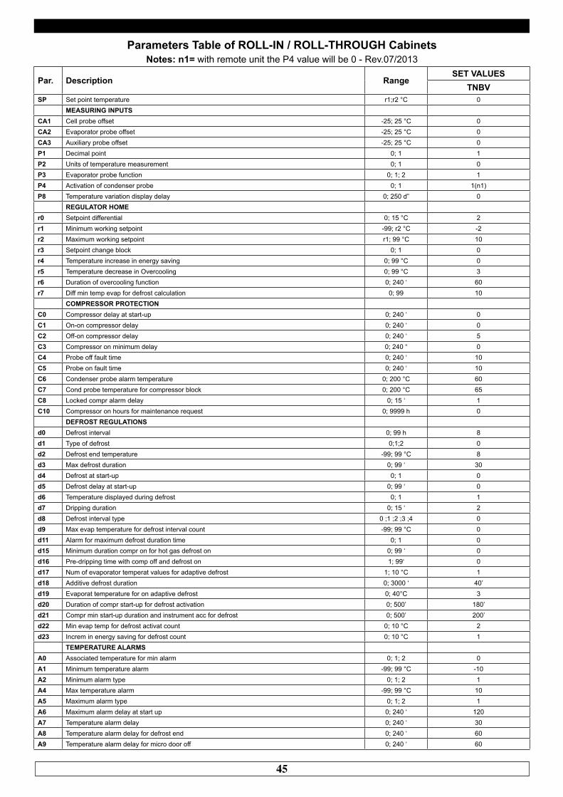
45
Parameters Table of ROLL-IN / ROLL-THROUGH Cabinets Notes: n1= with remote unit the P4 value will be 0 - Rev.07/2013
Par. Description RangeSET VALUES
TNBVSP Set point temperature r1;r2 °C 0
MEASURING INPUTSCA1 Cell probe offset -25; 25 °C 0CA2 Evaporator probe offset -25; 25 °C 0CA3 Auxiliary probe offset -25; 25 °C 0P1 Decimal point 0; 1 1P2 Units of temperature measurement 0; 1 0P3 Evaporator probe function 0; 1; 2 1P4 Activation of condenser probe 0; 1 1(n1)P8 Temperature variation display delay 0; 250 d” 0
REGULATOR HOMEr0 Setpoint differential 0; 15 °C 2r1 Minimum working setpoint -99; r2 °C -2r2 Maximum working setpoint r1; 99 °C 10r3 Setpoint change block 0; 1 0r4 Temperature increase in energy saving 0; 99 °C 0r5 Temperature decrease in Overcooling 0; 99 °C 3r6 Duration of overcooling function 0; 240 ‘ 60r7 Diff min temp evap for defrost calculation 0; 99 10
COMPRESSOR PROTECTIONC0 Compressor delay at start-up 0; 240 ‘ 0C1 On-on compressor delay 0; 240 ‘ 0C2 Off-on compressor delay 0; 240 ‘ 5C3 Compressor on minimum delay 0; 240 “ 0C4 Probe off fault time 0; 240 ‘ 10C5 Probe on fault time 0; 240 ‘ 10C6 Condenser probe alarm temperature 0; 200 °C 60C7 Cond probe temperature for compressor block 0; 200 °C 65C8 Locked compr alarm delay 0; 15 ‘ 1C10 Compressor on hours for maintenance request 0; 9999 h 0
DEFROST REGULATIONSd0 Defrost interval 0; 99 h 8d1 Type of defrost 0;1;2 0d2 Defrost end temperature -99; 99 °C 8d3 Max defrost duration 0; 99 ‘ 30d4 Defrost at start-up 0; 1 0d5 Defrost delay at start-up 0; 99 ‘ 0d6 Temperature displayed during defrost 0; 1 1d7 Dripping duration 0; 15 ‘ 2d8 Defrost interval type 0 ;1 ;2 ;3 ;4 0d9 Max evap temperature for defrost interval count -99; 99 °C 0d11 Alarm for maximum defrost duration time 0; 1 0d15 Minimum duration compr on for hot gas defrost on 0; 99 ‘ 0d16 Pre-dripping time with comp off and defrost on 1; 99‘ 0d17 Num of evaporator temperat values for adaptive defrost 1; 10 °C 1d18 Additive defrost duration 0; 3000 ‘ 40’d19 Evaporat temperature for on adaptive defrost 0; 40°C 3d20 Duration of compr start-up for defrost activation 0; 500’ 180’d21 Compr min start-up duration and instrument acc for defrost 0; 500’ 200’d22 Min evap temp for defrost activat count 0; 10 °C 2d23 Increm in energy saving for defrost count 0; 10 °C 1
TEMPERATURE ALARMSA0 Associated temperature for min alarm 0; 1; 2 0A1 Minimum temperature alarm -99; 99 °C -10A2 Minimum alarm type 0; 1; 2 1A4 Max temperature alarm -99; 99 °C 10A5 Maximum alarm type 0; 1; 2 1A6 Maximum alarm delay at start up 0; 240 ‘ 120A7 Temperature alarm delay 0; 240 ‘ 30A8 Temperature alarm delay for defrost end 0; 240 ‘ 60A9 Temperature alarm delay for micro door off 0; 240 ‘ 60
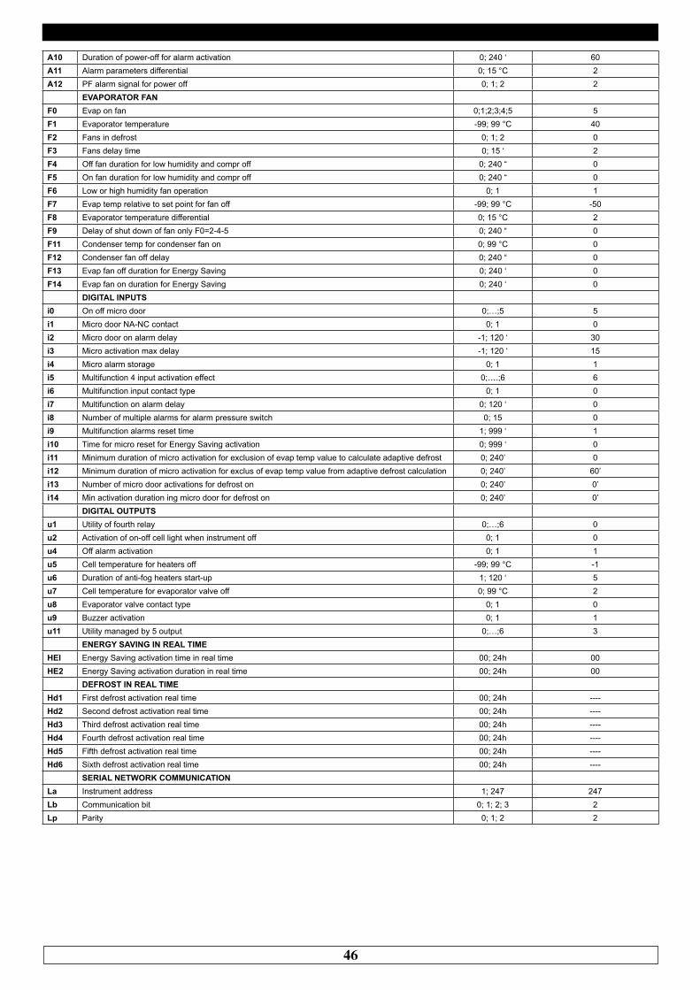
46
A10 Duration of power-off for alarm activation 0; 240 ‘ 60A11 Alarm parameters differential 0; 15 °C 2A12 PF alarm signal for power off 0; 1; 2 2
EVAPORATOR FANF0 Evap on fan 0;1;2;3;4;5 5F1 Evaporator temperature -99; 99 °C 40F2 Fans in defrost 0; 1; 2 0F3 Fans delay time 0; 15 ‘ 2F4 Off fan duration for low humidity and compr off 0; 240 “ 0F5 On fan duration for low humidity and compr off 0; 240 “ 0F6 Low or high humidity fan operation 0; 1 1F7 Evap temp relative to set point for fan off -99; 99 °C -50F8 Evaporator temperature differential 0; 15 °C 2F9 Delay of shut down of fan only F0=2-4-5 0; 240 “ 0F11 Condenser temp for condenser fan on 0; 99 °C 0F12 Condenser fan off delay 0; 240 “ 0F13 Evap fan off duration for Energy Saving 0; 240 ‘ 0F14 Evap fan on duration for Energy Saving 0; 240 ‘ 0
DIGITAL INPUTSi0 On off micro door 0;…;5 5i1 Micro door NA-NC contact 0; 1 0i2 Micro door on alarm delay -1; 120 ‘ 30i3 Micro activation max delay -1; 120 ‘ 15i4 Micro alarm storage 0; 1 1i5 Multifunction 4 input activation effect 0;….;6 6i6 Multifunction input contact type 0; 1 0i7 Multifunction on alarm delay 0; 120 ‘ 0i8 Number of multiple alarms for alarm pressure switch 0; 15 0i9 Multifunction alarms reset time 1; 999 ‘ 1i10 Time for micro reset for Energy Saving activation 0; 999 ‘ 0i11 Minimum duration of micro activation for exclusion of evap temp value to calculate adaptive defrost 0; 240’ 0i12 Minimum duration of micro activation for exclus of evap temp value from adaptive defrost calculation 0; 240’ 60’i13 Number of micro door activations for defrost on 0; 240’ 0’i14 Min activation duration ing micro door for defrost on 0; 240’ 0’
DIGITAL OUTPUTSu1 Utility of fourth relay 0;…;6 0u2 Activation of on-off cell light when instrument off 0; 1 0u4 Off alarm activation 0; 1 1u5 Cell temperature for heaters off -99; 99 °C -1u6 Duration of anti-fog heaters start-up 1; 120 ‘ 5u7 Cell temperature for evaporator valve off 0; 99 °C 2u8 Evaporator valve contact type 0; 1 0u9 Buzzer activation 0; 1 1u11 Utility managed by 5 output 0;…;6 3
ENERGY SAVING IN REAL TIMEHEI Energy Saving activation time in real time 00; 24h 00HE2 Energy Saving activation duration in real time 00; 24h 00
DEFROST IN REAL TIMEHd1 First defrost activation real time 00; 24h ----Hd2 Second defrost activation real time 00; 24h ----Hd3 Third defrost activation real time 00; 24h ----Hd4 Fourth defrost activation real time 00; 24h ----Hd5 Fifth defrost activation real time 00; 24h ----Hd6 Sixth defrost activation real time 00; 24h ----
SERIAL NETWORK COMMUNICATIONLa Instrument address 1; 247 247Lb Communication bit 0; 1; 2; 3 2Lp Parity 0; 1; 2 2
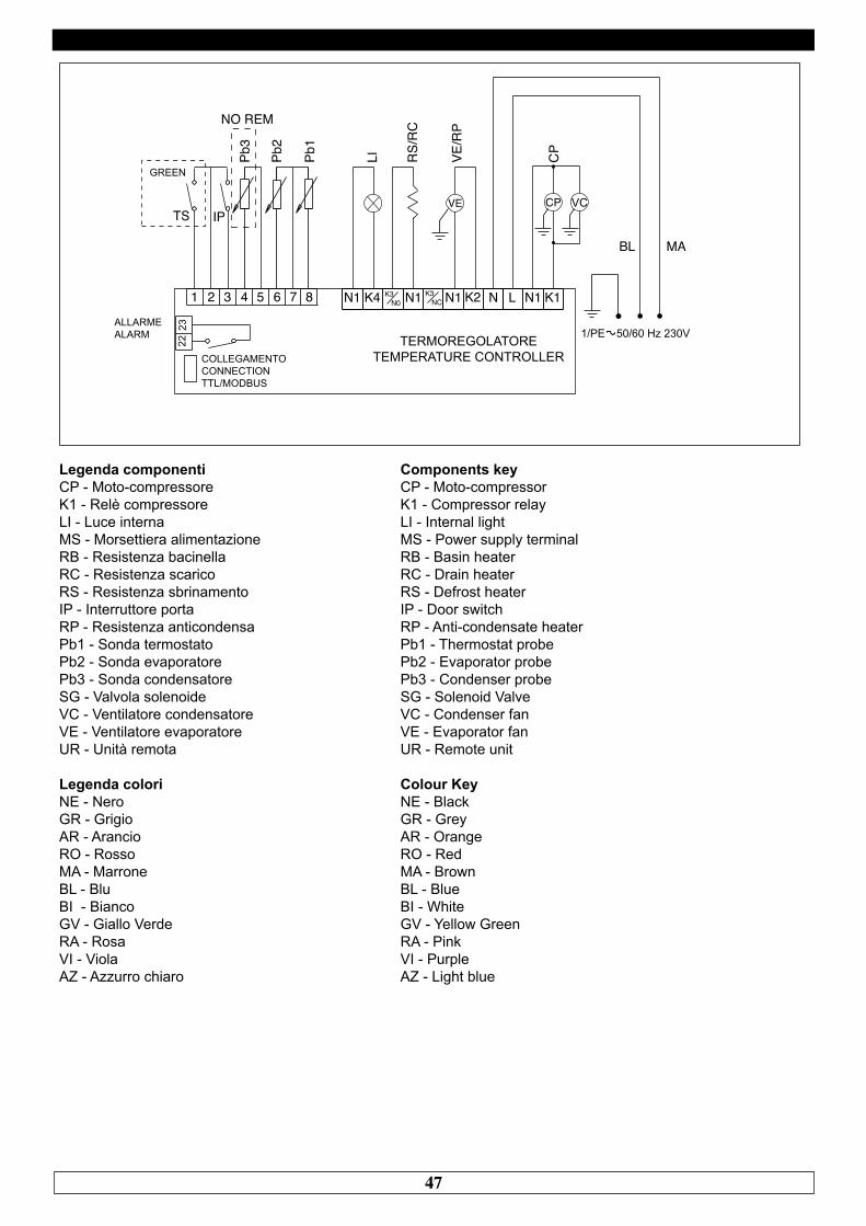
47
1 2 3 4 5 6 7 8 N1 K4 K3 N1 N1 K2 N L N1 K1N0K3
NC
BL MA
IP
Pb3
Pb2
Pb1
LI VE/R
P
RS/
RC
CP
VCTS
2223
NO REM
COLLEGAMENTOCONNECTIONTTL/MODBUS
TERMOREGOLATORETEMPERATURE CONTROLLER
Legenda componentiCP - Moto-compressoreK1 - Relè compressoreLI - Luce internaMS - Morsettiera alimentazioneRB - Resistenza bacinellaRC - Resistenza scaricoRS - Resistenza sbrinamentoIP - Interruttore portaRP - Resistenza anticondensaPb1 - Sonda termostatoPb2 - Sonda evaporatorePb3 - Sonda condensatoreSG - Valvola solenoideVC - Ventilatore condensatoreVE - Ventilatore evaporatoreUR - Unità remota
Legenda coloriNE - NeroGR - GrigioAR - ArancioRO - RossoMA - MarroneBL - BluBI - BiancoGV - Giallo VerdeRA - RosaVI - ViolaAZ - Azzurro chiaro
GREEN
ALLARMEALARM
Components keyCP - Moto-compressorK1 - Compressor relayLI - Internal lightMS - Power supply terminalRB - Basin heaterRC - Drain heaterRS - Defrost heaterIP - Door switchRP - Anti-condensate heaterPb1 - Thermostat probePb2 - Evaporator probePb3 - Condenser probeSG - Solenoid ValveVC - Condenser fanVE - Evaporator fanUR - Remote unit
Colour KeyNE - BlackGR - GreyAR - OrangeRO - RedMA - BrownBL - BlueBI - WhiteGV - Yellow GreenRA - PinkVI - PurpleAZ - Light blue
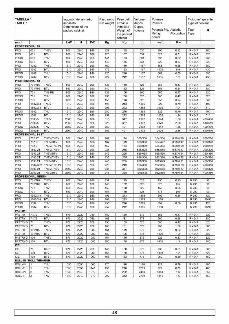
48
TABELLA 1 TABLE 1
Ingombri del armadioimballatoDimensions of the packed cabinet
Peso nettoNet weight
Peso dell’armadio imballatoWeight ofthe packedcabinet
Volume depos. Depos.volume
Potenze Powers
Fluido refrigerante Type of coolant
Potenza frig. Refrig. power
Assorb. Absorption
Tipo Type
g
mod. L-W H P-D Kg Kg Lt. watt KwPROFESSIONAL 70PRO 601 TNBV 860 2240 920 122 135 534 396 0,32 R 404A 280PRO 601 BTV 860 2240 920 125 137 534 629 0,71 R 404A 320PROG 601 TNV 860 2240 920 141 153 534 396 0,32 R 404A 280PROG 601 BTV 860 2240 920 143 155 534 629 0,87 R 404A 320PRO 1202 TNBV 1610 2240 920 169 189 1167 668 0,55 R 404A 350PRO 1202 BTV 1610 2240 920 173 193 1167 1035 0,9 R 404A 430PROG 1202 TNV 1610 2240 920 220 240 1167 668 0,55 R 404A 350PROG 1202 BTV 1610 2240 920 222 242 1167 1035 1,2 R 404A 430PROFESSIONAL 80PRO 701/702 TNBV 860 2240 920 137 149 625 565 0,47 R 404A 320PRO 701/702 BTV 860 2240 920 140 152 625 855 0,84 R 404A 380PRO 701 TNS PE 860 2240 920 138 150 300 565 0,47 R 404A 320PROG 701 TNV 860 2240 920 156 168 625 565 0,47 R 404A 320PROG 701 BTV 860 2240 920 158 170 625 855 0,94 R 404A 380PRO 1502/3/4 TNBV 1610 2240 920 193 213 1365 922 0,79 R 404A 400PRO 1502/3/4 BTV 1610 2240 920 203 223 1365 1035 1,04 R 404A 510PROG 1502 TNV 1610 2240 920 250 270 1365 922 0,79 R 404A 400PROG 1502 BTV 1610 2240 920 252 272 1365 1035 1,24 R 404A 510PRO 2303/5 TNBV 2360 2240 920 315 347 2102 1844 1,58 R 404A 400/400PRO 2303/5 BTV 2360 2240 920 325 357 2102 2070 2,08 R 404A 510/510PROG 2303/5 TNV 2360 2240 920 369 401 2102 1844 1,58 R 404A 400/400PROG 2303/5 BTV 2360 2240 920 389 421 2102 2070 2,36 R 404A 510/510PROFESSIONAL 80 2TPRO 702 2T TNBV/TNBV 860 2240 920 162 174 300/300 354/354 0,29/0,29 R 404A 280/280PRO 702 2T TNBV/BTV 860 2240 920 167 179 300/300 354/427 0,29/0,47 R 404A 280/320PRO 702 2T TNBV/TNS PE 860 2240 920 162 174 300/300 354/354 0,29/0,29 R 404A 280/280PRO 1502 2T TNBV/TNBV 1610 2240 920 235 255 625/625 565/565 0,47/0,47 R 404A 320/320PRO 1502 2T TNBV/BTV 1610 2240 920 245 265 625/625 565/856 0,47/0,84 R 404A 320/380PRO 1503 2T TNBV/TNBV 1610 2240 920 235 255 966/300 922/396 0,79/0,32 R 404A 400/320PRO 1503 2T TNBV/BTV 1610 2240 920 245 265 966/300 922/629 0,79/0,71 R 404A 400/380PRO 1502/3 2T TNBV/TNS PE 1610 2240 920 229 249 966/300 922/396 0,79/0,29 R 404A 400/380PRO 2303 2T TNBV/TNBV 2360 2240 920 335 357 1365/625 922/565 0,79/0,47 R 404A 400/320PRO 2303 2T TNBV/BTV 2360 2240 920 346 368 1365/625 922/856 0,79/0,84 R 404A 400/380PROFESSIONAL GREENPRO 701/702 TNBV 860 2240 920 137 149 625 450 0,25 R 290 90PRO 701/702 BTV 860 2240 920 140 152 625 575 0,5 R 290 90PROG 701 TNV 860 2240 920 156 168 625 450 0,25 R 290 90PROG 701 BTV 860 2240 920 158 170 625 575 0,6 R 290 90PRO 1502/3/4 TNBV 1610 2240 920 193 213 1365 699 0,38 R 290 120PRO 1502/3/4 BTV 1610 2240 920 203 223 1365 1150 1 R 290 90/90PROG 1502 TNV 1610 2240 920 250 270 1365 699 0,38 R 290 120PROG 1502 BTV 1610 2240 920 252 272 1365 1150 1 R 290 90/90PASTRYPASTRY 71/72 TNBV 870 2220 760 150 165 573 565 0,47 R 404A 320PASTRY 71/72 BTV 870 2220 760 166 181 573 960 0,98 R 404A 380PASTRYG 71 TNBV 870 2220 760 150 165 573 565 0,47 R 404A 320PASTRYG 71 BTV 870 2220 760 166 181 573 960 1,08 R 404A 380PASTRY 101/102 TNBV 870 2220 1080 164 179 875 922 0,83 R 404A 320PASTRY 101/102 BTV 870 2220 1080 180 195 875 1400 1,2 R 404A 380PASTRYG 100 TNBV 870 2220 1080 164 179 875 922 0,83 R 404A 320PASTRYG 100 BTV 870 2220 1080 180 195 875 1400 1,3 R 404A 380ICEICE 70 BTST 870 2220 760 145 160 573 730 0,61 R 404A 500ICE 100 BTV 870 2220 1060 165 180 875 1400 1,2 R 404A 620ICE 100 BTST 870 2220 1060 168 183 775 960 0,89 R 404A 450ROLL-IN / ROLL-THROUGHROLL-IN 1 TNV 1050 2350 1060 175 190 1120 922 0,79 R 404A 400ROLL-TH 1 TNV 1050 2350 1147 195 210 1233 922 0,79 R 404A 400ROLL-IN 2 TNV 1840 2340 1079 272 292 2466 1844 1,6 R 404A 550ROLL-TH 2 TNV 1840 2340 1079 292 312 2700 1844 1,6 R 404A 550
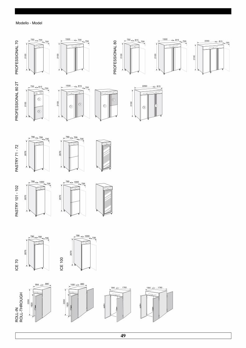
49
Modello - Model
700750
2100
7001500 700
2100
700 815750
2100
7001500 815
2100
700 2250
2100
815 700
815750
2100
700
2
1
1500 815
2100
700
21
2
1
2250 815
2100
21
PR
OFE
SS
ION
AL
70
PR
OFE
SS
ION
AL
80
PR
OFE
SS
ION
AL
80 2
T
700790
2070
735
1000790
2070
735
700790
2070
735
1000790
2070
735
PAS
TRY
71 -
72PA
STR
Y 10
1 - 1
02
1000790
2070
735700790
2070
735
ICE
70
ICE
100
994 880
182022
00
1081 880
182022
00
994 1760 1081 1760
RO
LL-IN
R
OLL
-TH
RO
UG
H
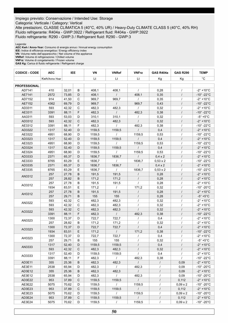
50
CODICE - CODE AEC IEE VN VNRef VNFrz GAS R404a GAS R290 TEMP
Kwh/Anno-Year Lt Lt Lt Kg Kg °C
Impiego previsto: Conservazione / Intended Use: StorageCategoria: Verticale / Category: VerticalAlte prestazioni, CLASSE CLIMATICA 5 (40°C, 40% UR) / Heavy-Duty CLIMATE CLASS 5 (40°C, 40% RH)Fluido refrigerante: R404a - GWP:3922 / Refrigerant fluid: R404a - GWP:3922Fluido refrigerante: R290 - GWP:3 / Refrigerant fluid: R290 - GWP:3 Legenda:AEC Kwh / Anno-Year: Consumo di energia annuo / Annual energy consumptionIEE: Indice di efficienza energetica / Energy efficiency indexVN: Volume netto dell’apparecchio / Net volume of the applianceVNRef: Volume di refrigerazione / Chilled volumeVNFrz: Volume di congelamento / Frozen volumeGAS Kg: Carica di fluido refrigerante / Refrigerant charge
PROFESSIONALAD7141 410 32,01 B 408,1 408,1 / 0,28 / -2° +10°CAE7141 2572 73,85 D 408,1 / 408,1 0,35 / -10° -22°CAD7152 914 41,50 C 969,7 969,7 / 0,35 / -2° +10°CAE7152 4362 69,79 D 969,7 / 969,7 0,43 / -10° -22°CAD3311 593 42,32 C 482,3 482,3 / 0,32 / -2° +10°CAE3311 3391 88,11 F 482,3 / 482,3 0,38 / -10° -22°CAA3311 593 53,03 D 310,1 310,1 / 0,32 / -5° +5°CAD3312 593 42,32 C 482,3 482,3 / 0,32 / -2° +10°CAE3312 3391 88,11 F 482,3 / 482,3 0,38 / -10° -22°CAD3322 1317 52,40 D 1159,5 1159,5 / 0,4 / -2° +10°CAE3322 4951 68,90 D 1159,5 / 1159,5 0,53 / -10° -22°CAD3323 1317 52,40 D 1159,5 1159,5 / 0,4 / -2° +10°CAE3323 4951 68,90 D 1159,5 / 1159,5 0,53 / -10° -22°CAD3324 1317 52,40 D 1159,5 1159,5 / 0,4 / -2° +10°CAE3324 4951 68,90 D 1159,5 / 1159,5 0,53 / -10° -22°CAD3333 2371 65,37 D 1836,7 1836,7 / 0,4 x 2 / -2° +10°CAE3333 8765 83,29 E 1836,7 / 1836,7 0,53 x 2 / -10° -22°CAD3335 2371 65,37 D 1836,7 1836,7 / 0,4 x 2 / -2° +10°CAE3335 8765 83,29 E 1836,7 / 1836,7 0,53 x 2 / -10° -22°C
AN3312257 27,78 B 191,5 191,5 / 0,28 / -2° +10°C257 28,82 B 171,2 171,2 / 0,28 / -2° +10°C
AO3312257 27,78 B 191,5 191,5 / 0,28 / -2° +10°C1934 83,51 E 171,2 / 171,2 0,32 / -10° -20°C
AH3312257 27,78 B 191,5 191,5 / 0,28 / -2° +10°C257 29,71 B 155 155 / 0,28 / -5° +5°C
AN3322593 42,32 C 482,3 482,3 / 0,32 / -2° +10°C593 42,32 C 482,3 482,3 / 0,32 / -2° +10°C
AO3322593 42,32 C 482,3 482,3 / 0,32 / -2° +10°C3391 88,11 F 482,3 / 482,3 0,38 / -10° -22°C
AN33231300 72,37 D 722,7 722,7 / 0,4 / -2° +10°C257 28,82 B 171,2 171,2 / 0,32 / -2° +10°C
AO33231300 72,37 D 722,7 722,7 / 0,4 / -2° +10°C1934 83,51 E 171,2 / 171,2 0,38 / -10° -22°C
AH33231300 72,37 D 722,7 722,7 / 0,4 / -2° +10°C257 29,71 B 155 155 / 0,32 / -5° +5°C
AN33331317 52,40 D 1159,5 1159,5 / 0,4 / -2° +10°C593 42,32 C 482,3 482,3 / 0,32 / -2° +10°C
AO33331317 52,40 D 1159,5 1159,5 / 0,4 / -2° +10°C3391 88,11 F 482,3 / 482,3 0,38 / -10° -22°C
AD3E11 355 25,36 B 482,3 482,3 / / 0,09 -2° +10°CAE3E11 2538 65,94 D 482,3 / 482,3 / 0,09 -10° -20°CAD3E12 355 25,36 B 482,3 482,3 / / 0,09 -2° +10°CAE3E12 2538 65,94 D 482,3 / 482,3 / 0,09 -10° -20°CAD3E22 953 37,89 C 1159,5 1159,5 / / 0,112 -2° +10°CAE3E22 5075 70,62 D 1159,5 / 1159,5 / 0,09 x 2 -10° -20°CAD3E23 953 37,89 C 1159,5 1159,5 / / 0,112 -2° +10°CAE3E23 5075 70,62 D 1159,5 / 1159,5 / 0,09 x 2 -10° -20°CAD3E24 953 37,89 C 1159,5 1159,5 / / 0,112 -2° +10°CAE3E24 5075 70,62 D 1159,5 / 1159,5 / 0,09 x 2 -10° -20°C
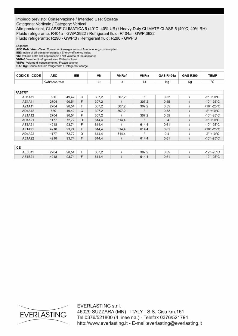
51
EVERLASTING s.r.l.46029 SUZZARA (MN) - ITALY - S.S. Cisa km.161 Tel.0376/521800 (4 linee r.a.) - Telefax 0376/521794http://www.everlasting.it - E-mail:[email protected]
CODICE - CODE AEC IEE VN VNRef VNFrz GAS R404a GAS R290 TEMP
Kwh/Anno-Year Lt Lt Lt Kg Kg °C
Impiego previsto: Conservazione / Intended Use: StorageCategoria: Verticale / Category: VerticalAlte prestazioni, CLASSE CLIMATICA 5 (40°C, 40% UR) / Heavy-Duty CLIMATE CLASS 5 (40°C, 40% RH)Fluido refrigerante: R404a - GWP:3922 / Refrigerant fluid: R404a - GWP:3922Fluido refrigerante: R290 - GWP:3 / Refrigerant fluid: R290 - GWP:3 Legenda:AEC Kwh / Anno-Year: Consumo di energia annuo / Annual energy consumptionIEE: Indice di efficienza energetica / Energy efficiency indexVN: Volume netto dell’apparecchio / Net volume of the applianceVNRef: Volume di refrigerazione / Chilled volumeVNFrz: Volume di congelamento / Frozen volumeGAS Kg: Carica di fluido refrigerante / Refrigerant charge
PASTRYAD1A11 550 49,42 C 307,2 307,2 / 0,32 / -2° +10°CAE1A11 2704 90,54 F 307,2 / 307,2 0,55 / -10° -25°CAZ1A11 2704 90,54 F 307,2 307,2 307,2 0,55 / +10° -25°CAD1A12 550 49,42 C 307,2 307,2 / 0,32 / -2° +10°CAE1A12 2704 90,54 F 307,2 / 307,2 0,55 / -10° -25°CAD1A21 1177 72,72 D 614,4 614,4 / 0,4 / -2° +10°CAE1A21 4218 93,74 F 614,4 / 614,4 0,61 / -10° -25°CAZ1A21 4218 93,74 F 614,4 614,4 614,4 0,61 / +10° -25°CAD1A22 1177 72,72 D 614,4 614,4 / 0,4 / -2° +10°CAE1A22 4218 93,74 F 614,4 / 614,4 0,61 / -10° -25°C
ICEAE0B11 2704 90,54 F 307,2 / 307,2 0,55 / -12° -25°CAE1B21 4218 93,74 F 614,4 / 614,4 0,61 / -12° -25°C


![Biomateriali [2] - BiomedicaHelp · residui, spessori ridotti, elevato sforzo appliato…) -> environmental stress cracking (vedi slide) ... - proprietà meccaniche adeguate all’appliazione](https://img.pdfslide.tips/doc/110x75/5c6e555a09d3f29e208b5391/biomateriali-2-residui-spessori-ridotti-elevato-sforzo-appliato-environmental.jpg)