Embed Size (px)
Citation preview


Indice Pag.
1. Generalità 3
2. Designazione 4
3. Gamma AM 5
4. Gamma AMM 6
5. Gamma AML 7
6. Gamma AMP 8
7. Gamma AMS 9
8. Apparecchiatura di precarica e controllo PC 10
9. Apparecchiatura di precarica e controllo PCM 11
10. Elementi di fissaggio 12
11. Installazione 13
12. Manutenzione 14
13. Rappresentanze nel mondo 15
Content Page
1. General 3
2. Designation 4
3. AM range 5
4. AMM range 6
5. AML range 7
6. AMP range 8
7. AMS range 9
8. Pre-loading and checking set PC 10
9. Pre-loading and checking set PCM 11
10. Support equipment 12
11. Installation 13
12. Maintenance 14
13. Branches and representatives all over the world 15
2
Progetto1 9-09-2005 15:10 Pagina 2

3
1.2 CostruzioneL’accumulatore, progettato e costruito secon-do la direttiva 97/23/CE, è costituito da uncorpo che porta sulla parte superiore l’attaccoper il gas, nella parte inferiore l’attacco per illiquido e contiene una membrana elasticaquale separatore fra i due fluidi.La membrana ha un dischetto (in acciaio alcarbonio, in acciaio inox o polimero), vulcaniz-zato nella parte inferiore che ne impediscel’estrusione attraverso il foro di attacco delliquido.Esistono tre versioni con il corpo in acciaio(AM-AMM e AML) e una in PVC (AMP) smon-tabili e riparabili.Una quinta versione (AMS) ha il corpo in accia-io saldato (fig. II), pertanto la membrana non èsostituibile. I materiali dei corpi e delle membrane, le carat-teristiche tecniche e dimensionali sono riporta-te nelle pag. 5-6-7-8-9.
1.2.1 Attacco lato gas•Per le serie AM-AMM-AML e AMP l’attacco
standard è costituito da una valvola di gon-fiaggio smontabile da 5/8” UNF (fig. IlI).
La versione saldata AMS ha invece l’attaccostandard filettato M28x1,5 (fig. IV).
•Su richiesta:- l’attacco azoto filettato M28x1,5, come indi-
cato in fig. IV (solo per le gamme AM e AMM).- Attacco azoto filettato 3/4” ISO 228 come indi-
cato in fig. V (solo per le gamme AM e AMM).- Attacco azoto versione T (v. pag. 9) a taratura
fissa (fornibile solo per la serie AMS).
1.2.2 Attacco lato liquido•La versione standard (fig. VI) per le gamme
AM-AMM-AML e AMP prevede un attacco E,filettato femmina, metrico o ISO 228 e, surichiesta, NPT o SAE come da tabelle a pag.5-6-7-8.
La gamma AMS prevede un unico attacco Eda 1/2” ISO 228.
•Su richiesta l’attacco liquido può essere for-nito nella versione W, con filettatura esterna edinterna (fig. VII), per i tipi AM 0,75÷5 e AML0,8-1,5.
Le dimensioni di questo attacco (W) per il tipoAMS si ricavano dalla tabella dimensioni apag. 9.
In alcuni casi è possibile la versione flangiata Fprecisando esattamente dimensioni e normati-ve della flangia.
1.2 ConstructionThe accumulator, designed and manufacturedaccording to directive 97/23/EC, consists of apressure vessel on which the gas connection islocated at the top part, while the fluid connectionis in the lower part.The body contains a flexible diaphragm acting asseparator between the two fluids.The diaphragm incorporates a button (in carbonsteel, in stainless steel or in polimer), bonded tothe lower part which prevents its extrusionthrough the hole of the liquid port.There are three versions with steel shell (AM-AMM e AML) plus one in PVC (AMP) all can bedisassembled and repaired.The fifth version (AMS) has the body in weldedsteel (fig. II), therefore the diaphragm is notexchangeable.The materials of construction of the shells anddiaphragms as well as the other technical anddimensional characteristics are given on pages 5-6-7-8-9.
1.2.1 Gas side connection•Standard connection for AM-AMM-AML and
AMP series consists of a removable inflatingvalve size 5/8" UNF (fig. IlI).
The welded version AMS has the standard con-nection threaded M28x1,5 (fig. IV).
•Upon request:- connection threaded M28x1,5 as shown in
fig. IV (only for versions AM and AMM).- Gas connection threaded 3/4” ISO228 as
shown in fig. V (only for versions AM andAMM).
- Gas connection design T (see page 9) withfixed precharge (available only for AMSrange).
1.2.2 Fluid port•The standard version (fig. VI) for series AM-
AMM-AML and AMP has a female threadedconnection E, either metric or BSP and, onrequest, NPT or SAE according to tables onpages 5-6-7-8.
The AMS range has only a fluid connection E1/2” ISO 228.
•On demand, AM 0,75÷5 and AML 0,8-1,5 canbe supplied with fluid connection version W withexternal and internal thread (Fig.VII).
The dimensions of this fluid connection for thetype AMS can be deduced from the dimen-sions table at pag. 9.
In some cases is possible to have the flangedversion F specifying exactly dimensions andstandards of the flange.
Generalità - General1
1.1 Definizione e funzionamentoL’accumulatore idropneumatico è un apparecchio che rende possibi-le, nei circuiti idraulici, un notevole accumulo di energia in spazi con-tenuti.Essendo i liquidi praticamente incomprimibili, perciò non idonei all’ac-cumulo di energia, lo scopo viene raggiunto sfruttando la grande com-primibilità dei gas.In pratica si usa un recipiente a pressione che contiene una membranaelastica, quale separatore fra il gas e il liquido, al cui interno è statoimmesso il gas (azoto) ad una pressione prestabilita (Po). Dal lato oppo-sto alla valvola di gonfiaggio c’è la connessione al circuito idraulico.Quando la pressione nel circuito supera la pressione di precarica Po illiquido entra nell’accumulatore comprimendone la membrana fintantoche le due pressioni, liquido-gas, non si siano eguagliate.In questo modo si è ottenuto un certo accumulo di liquido in pressio-ne, vale a dire una riserva di energia potenziale di cui si potrà disporreper le più svariate esigenze.
1.1 Definition and operationThe hydropneumatic accumulator allows a considerable accumulationof energy within confined spaces in hydraulic circuits.As liquids are practically incompressible and not therefore suitable forenergy accumulation, such purpose is achieved by making use of thehigh compressibility of gases.In practice a pressure vessel is used containing a separator dia-phragm, as flexible barrier between the hydraulic fluid and the nitrogengas. Through an inflating valve the inert gas, at a present pressure (Po),is indroduced into the diaphragm. Connection to the hydraulic circuit islocated on the side opposite to the gas-fill valve.When the circuit pressure exceeds the precharging pressure Po, theliquid enters the accumulator thereby compressing the diaphragm untilthe two pressures (liquid-gas) are equal.In this way is obtained a certain store of liquid under pressure, i.e. areserve of potential energy which can be used for a lot of differentapplications.
Fig. I
Fig. II
Fig. III
Fig. IV
Fig. V
Fig. VI
Fig. VII

4
Designazione - Designation2
2.1 Scelta dell’accumulatoreDopo aver definito la grandezza dell’accumulatore (per il dimensiona-mento v. par. 3 del catalogo 1007 degli accumulatori a sacca) si puòprocedere alla sua completa designazione tenendo presente che:
•La pressione di lavoro P2 sia inferiore alla pressione massimad’esercizio PS relativa al tipo prescelto.
•Il rapporto di pressione P2/P0 (pressione di lavoro/pressione di pre-carica) sia ≤ 6 (per la serie AMS ≤ 8).
•Il materiale del corpo e della membrana siano compatibili con Illiquido usato (fluidi del Gruppo 2 per le versioni standard. Per altrifluidi chiedere al ns. servizio tecnico).
•Le temperature di lavoro siano comprese nel campo delle temperatu-re d’esercizio TS ammissibili sia per il corpo che per il materiale dellamembrana.
•Il collaudo corrisponda alle prescrizioni del luogo di installazione.
Ogni serie riportata in catalogo ha proprie caratteristiche di forma,dimensioni, peso, attacchi, grandezze e materiali disponibili, prestazio-ni tecniche, ecc. che tendono a soddisfare le più svariate esigenze.Naturalmente per applicazioni speciali è consigliabile rivolgersi al nostroservizio tecnico.
Attenzione: È necessario specificare nell’ordine il valore della pre-carica d’azoto desiderata.In caso contrario l’accumulatore verrà fornito con precari-ca di stoccaggio di 30 bar.
2.2 Codice di identificazioneNella designazione si tenga presente che la capacità, la pressione-d’esercizio, il materiale del corpo, ecc. vanno scelti solo fra quelliprevisti per ciascuna gamma di accumulatori (v. pag. 5-6-7-8-9).La pressione di precarica va precisata a parte, così come l’attacco liqui-do, se non standard, e l’elastomero per alimenti.ESEMPIO DI DESIGNAZIONE:
2.1 Accumulator selectionAfter the right selection of the accumulator size (for the selection seesection 3 of bladder accumulator catalogue 1007) proceed with itscomplete designation observing that:
•The operating pressure P2 must be lower than the maximum wor-king pressure PS of the chosen type.
•The pressure ratio P2/P0 (operating pressure/precharge pressure)must be ≤ 6 (range AMS ≤ 8).
•The material of the body and diaphragm must be compatible withthe liquids used (fluids of Group 2 for the standard version.For other liquids, ask to our technical department).
•Operating temperatures must be included into the working tempera-ture range TS admissible both for the body and for the diaphragmmaterial.
•The test have to be in conformity with regulations of the Country ofinstallation.
Each series given in the catalogue has its own characteristics of shape,dimensions, weight, connection, size and available materials, technicalperformance levels, etc. such as to meet the widely differenting requi-rements.Obviously for special applications it is advisable to consult our TechnicalService Department.
N.B.: Please specify the required nitrogen precharge pressurein the order.If not, the accumulator will be supplied with the storage pre-charge pressure of 30 bar.
2.2 Identification codeWhen selecting an accumulator bear in mind that capacity,working pressure, shells material, etc. can only be chosen fromthose available for each series of accumulators (see pages 5 to 9). Theprecharge pressure should be specified separately as well as the fluidconnection, if not standard, and the polymer for food.Sample of designation:
AM 1,5 P 210 C G 8 -
Serie diaccumulatoreAccumulator
series
CapacitànominaleNominalvolume
l
Materialedel corpo
Shellmaterial
Attaccolato liquidoFluid port
connection
CollaudiTesting
Attaccolato gas
Gasconnection
Press. maxammiss.Allowablepressure
bar
MaterialeMaterial
Membrana - DiaphragmTemperat.esercizio
Temperaturerange
G = Filettato intern.ISO 228BSPparallelthread
M = Filettato intern.metricoMetricthread
P = Filettato intern.NPTNPTthread
S = Filett. SAESAE O-Ringport
W= Filett. internaed esterna(fig. V pag. 3)Internaland externalthreaed
F = Flangiato(precis. tipo)With flange(specifystandard)
R = Riduzione(solo per AM10da precisare)(only for AM10specify data)
0=di fabbricaFactorytesting
1=GOST(Russia)
8=CE/PED (dir. 97/23/CE)
9=ATEX
10=altri surichiestaother on
request
– = standardcon valvola5/8” UNFStadardwith valve5/8” UNF
M = M28x1,5(fig. IVpag. 3)
R = 3/4” ISO 228(fig. Vpag. 3)
T = taratura fissa(vedi pag. 9)fixedprecharge(see page 9)
X = valvola gas2072 inoxStainlesssteelgas valve2072
C = Acciaio alcarbonioCarbonsteel
F = Acciaio alcarbonio- 40°CCarbonsteel -40°C
N = Acciaio alcarbonionichelatoNickelcoatedcarbonsteel
X = AcciaioinoxStainlesssteel
L = PVC(PP o PVDFsu richiesta)
V = Conrivestim.specialiWithspecialcoating
210-330(AM e AMM)
acciaio alcarbonioCarbon
steel
150-250(AM e AMM)
acciaioinossidabile
Stainlesssteel
250-350(AML)
acciaio alcarbonioCarbon
steel
10(AMP)
PVC - PPe PVDF
100-330(AMS)
acc. al carb.Carb. steel
100(AMS)
acc. inoxStainless
steel
P = NBR (Nitrile standard)(Standard Nitrile)
B= IIR (Butile - Butyl)N= CR (Cloroprene)
(Chloropreme)E = EPM - EPDM
(Etilene - propilene)(Ethylene - propylene)
A = NBR-IIR-EPDM-NR-MVQ(Per alimenti - For food)
C= NR (Caucciù naturale(Natural rubber)
F = NBR (Perbunan -40°C)(Nitrile for -40°C)
H= NBR (per idrocarburi)(for hydrocarbons)
K= HNBR (Nitrile idrogenato)(Idrogenated nitrile)
S = MVQ (Siliconi)(Silicons)
V = FKM (Gomma flurorata)(Flurorated rubber)
Y = ECO (Epicloridrina)(Epichloridrin)
Z = ACM (Poliacrilato)(Acrilyc)
0,05
0,1
0,16
0,25
0,32
0,35
0,5
0,75
0,8
1
1,4
1,5
2
2,5
4
5
10
AM(Pag. 5)
AMM(Pag. 6)
AML(Pag. 7)
AMP(Pag. 8)
AMS(Pag. 9)
-15 +80°C
-20 +90°C-10 +90°C
-20 +110°C
1)
-20 +70°C
-40 +70°C
-10 +80°C
-30 +130°C
-30 +130°C
-10 +150°C
-30 +110°C
-20 +130°C
1-La membrana per alimenti si può ricavare dagli elastomeri base indicati, ciascuno dei quali ha un suo specifico campo di temperature.1-The diaphragm for food can be chosen from the basic polymers above mentioned, each of them has its specific temperature range.

5
Gamma - Range AM3
3.2 Caratteristiche costruttiveL’ESECUZIONE STANDARD PREVEDE:• Corpo in acciaio al carbonio verniciato esternamente con una mano
di antiruggine.• Membrana e guarnizioni in gomma nitrilica antiolio (P).• Attacco gas 5/8" UNF (valvola 2072, in acciaio al carbonio fosf.).• Attacco liquido filettato femmina (dimensioni E standard).• Costruzione e certificazione secondo direttiva 97/23/CE.
(I tipi AM 0,5 e 0,75 sono esenti da certificazione e marchiatura CE).
SU RICHIESTA• CORPO NICHELATO, spess. 25 micron (altri spessori da precisa-
re) o con rivestimento speciale.• CORPO INOX AISI 316 (PS = 150 bar e 210 bar).• CORPO INOX SAF 2205 (PS = 250 bar).• VALVOLA GONFIAGGIO 2072 in acciaio inossidabile.• MEMBRANA in B-N-E-A-C-F-H-K-S-V-Y-Z (v. pag. 4).• ATTACCO GAS M28x1,5 o 3/4” ISO 228 (fig. IV e V pag. 3).• ATTACCO LIQUIDO: filettatura speciale (dimensioni E su richiesta).• ATTACCO LIQUIDO FLANGIATO (precisare DN, PN e normativa).
3.2 Construction featuresSTANDARD VERSION INCLUDES:• Carbon steel shell on painted outside with a coat of rust inhibitor.• Diaphragm and gaskets in standard nitrile rubber (P).• Gas connection: 5/8" UNF (gas valve 2072, in carbon steel).• Fluid connection: female parallel thread (Dimensions E standard).• Construction and testing according to directive 97/23/EC.
(The types AM 0,5 - 0,75 are exempted from certification andmarking EC).
ON REQUEST• SHELL PROTECTED with nickel coating 25 micron (other
thickness to specify) or other special coating.• SHELL IN STAINLESS STEEL AISI 316 (PS = 150 bar e 210 bar).• SHELL IN STAINLESS STEEL SAF 2205 (PS = 250 bar).• GAS VALVE 2072 in stainless steel.• DIAPHRAGM in B-N-E-A-C-F-H-K-S-V-Y-Z (see page 4).• GAS CONNECTION: M28x1,5 or 3/4” ISO 228 (fig. IV-V page 3).• FLUID CONNECTION: special thread (dimensions E on request).• FLANGED FLUID CONNECTION (specify data of flange).
3.1 Caratteristiche tecniche - Technical features
Esecuzione avvitata, riparabile Screwed shell, repairable modelsPressione d’esercizio max (PS) Max working pressure (PS) 210 bar (330 bar per AM 0,5 - for AM 0,5)Pressione di prova (PT) Test pressure (PT) PS x 1,43Temperature d’esercizio min. e max (TS) Temperature range (TS) -20 +150°C (*) Rapporto di pressione max (P2/Po) Allowable pressure ratio (P2/Po) 6 : 1Capacità nominali (litri) Nominal capacities (litres) 0,5 - 0,75 - 1,5 - 2,5 - 4 - 5 - 10(*) Valori suscettibili di restrizioni in funzione del materiale della membrana. Values susceptible of restrictions due to the diaphragm material.
3.3 Dimensioni - Dimensions
3.4 Codice ricambi - Spare parts code
AM 0,5 I 210 - 330 0,48 4 M18x1,5 1/2”NPT G/P1/2”- G/P3/4” - SAE8 - SAE12 172 94 116 36AM 0,75 I 210 - 330 0,72 6 M18x1,5 3/4”NPT G/P1/2”- G/P3/4” - SAE8 - SAE12 189 116 137 40AM 1,5 II 210 - 330 1,4 9,7 M18x1,5 3/4”NPT G/P1/2”- G/P3/4” - SAE8 - SAE12 285 120 137 40AM 2,5 II 210 - 330 2,4 14,4 G 3/4” 3/4”NPT G/P1/2”- G/P3/4” - SAE8 - SAE12 - M18x1,5 440 120 137 40AM 4 II 210 - 330 3,8 24 G 3/4” 1”NPT M18x1,5-G/P1/2”-P3/4”-G/P1”-SAE12-SAE20 355 174 198 55AM 5 II 210 - 330 4,72 27 G 3/4” 1”NPT M18x1,5-G/P1/2”-P3/4”-G/P1”-SAE12-SAE20 422 174 198 55AM 10 III 210 - 330 102 46 G 1”1/4 1”1/4NPT P 1”1/4-R 3/8”-1/2”-3/4”BSP - SAE20 767 174 198 60
123
2)Membrana - diaphragmValvola gas - Gas valve2)Serie guarnizioni - Gasket set
10097/... 10098/... 10198/...
2087/...
10199/...2072
2087/...
10296/...
2088/...
10297/...
2088/...
10366/...
2089/...
TipoType
Pos.Item
DescrizioneDescription
Accumulatore tipo - Accumulator typeAM 0.5 AM 0.75 AM 1,5 AM 2,5 AM 4 AM 5 AM 10
Fig.
*Pressioned’esercizio
Workingpressure
bar
VolumegasGas
volumeL
Pesoa secco
Dryweight
kgStandard
Carbon steel Inox Su richiesta - on request mm mm
ø B ø D
Chiave(A/F)
CA
mm mm
Attacco liquidoFluid connection
1)E
1) Filettatura: M = metrica; G = BSP cilindrica; P = conica NPT; R = riduzione - Thread: M = metric; G = BSP parallel; P = NPT thread; R = adapter
* Versione standard in acciaio al carbonio - standard version in carbon steel.
2) Per la completa designazione della membrana e delle guarnizioni, far seguire al codice la lettera corrispondente all’elastomero scelto (vedi pag. 4)For the complete order code of diaphragm and gasket set, let follow to number code, the correspondent letter of selected elastomer (see page 4)
Salvo modifiche Subject to change
Fig. I Fig. II Fig. III
6
AMM 0,05 210 0,05 1,4 M18x1,5 1/2”NPT G/P1/2” - SAE8 108 – 65 40AMM 0,1 210 - 330 0,1 1,9 M18x1,5 1/2”NPT G/P1/2” - SAE8 131 73 77 36AMM 0,35 210 - 330 0,322 2,9 M18x1,5 1/2”NPT G/P1/2” - SAE8 157 94 99 36
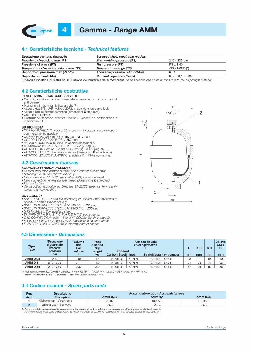
Gamma - Range AMM4
4.2 Caratteristiche costruttiveL’ESECUZIONE STANDARD PREVEDE:• Corpo in acciaio al carbonio verniciato esternamente con una mano di
antiruggine.• Membrana in gomma nitrilica antiolio (P).• Attacco gas 5/8" UNF (valvola 2072, in acciaio al carbonio fosf.).• Attacco liquido filettato femmina (dimensioni E standard).• Collaudo di fabbrica.• Costruzione secondo direttiva 97/23/CE (esenti da certificazione e
marchiatura CE).
SU RICHIESTA• CORPO NICHELATO, spess. 25 micron (altri spessori da precisare) o
con rivestimento speciale.• CORPO INOX AISI 316 (PS = 150 bar e 210 bar)• CORPO INOX SAF 2205 (PS = 250 bar).• VALVOLA GONFIAGGIO 2072 in acciaio inossidabile.• MEMBRANA in B-N-E-A-C-F-H-K-S-V-Y-Z (v. pag. 4).• ATTACCO GAS M28x1,5 o 3/4” ISO 228 (fig. IV e V pag. 3).• ATTACCO LIQUIDO: filettatura speciale (dimensioni E su richiesta).• ATTACCO LIQUIDO FLANGIATO (precisare DN, PN e normativa).
4.2 Construction featuresSTANDARD VERSION INCLUDES:• Carbon steel shell, painted outside with a coat of rust inhibitor.• Diaphragm in standard nitrile rubber (P).• Gas connection: 5/8" UNF (gas valve 2072, in carbon steel).• Fluid connection: female parallel thread (dimensions E standard).• Factory testing.• Construction according to Directive 97/23/EC (exempt from certifi-
cation and marking EC).
ON REQUEST• SHELL PROTECTED with nickel coating 25 micron (other thickness to
specify) or other special coating.• SHELL IN STAINLESS STEEL AISI 316 (PS = 150 bar).• SHELL IN STAINLESS STEEL SAF 2205 (PS = 250 bar).• GAS VALVE 2072 in stainless steel.• DIAPHRAGM in B-N-E-A-C-F-H-K-S-V-Y-Z (see page 4).• GAS CONNECTION: M28x1,5 or 3/4” ISO 228 (fig. IV-V page 3).• FLUID CONNECTION: special thread (dimensions E on request).• FLANGED FLUID CONNECTION (specify data of flange).
4.3 Dimensioni - Dimensions
4.4 Codice ricambi - Spare parts code
Salvo modifiche Subject to change
12
2) Membrana - DiaphragmValvola gas - Gas valve
10091/...2072
10095/...2072
10096/...2072
TipoType
Pos.Item
DescrizioneDescription
Accumulatore tipo - Accumulator typeAMM 0,05 AMM 0,1 AMM 0,35
*Pressioned’esercizio
Workingpressure
bar
VolumegasGas
volumeL
Pesoa secco
Dryweight
kgStandard
Carbon Steel Inox Su richiesta - on request mm mm
ø B ø D
Chiave(A/F)
CA
mm mm
Attacco liquidoFluid connection
1)E
1) Filettatura: M = metrica; G = BSP cilindrica; P = conica NPT - Thread: M = metric; G = BSP parallel; P = NPT thread
* Versione standard in acciaio al carbonio - standard version in carbon steel.
2) Per la completa designazione della membrana, far seguire al codice la lettera corrispondente all’elastomero scelto (vedi pag. 4).For the complete order code of diaphragm, let follow to number code, the correspondent letter of selected elastomer (see page 4).
4.1 Caratteristiche tecniche - Technical features
Esecuzione avvitata, riparabile Screwed shell, repairable modelsPressione d’esercizio max (PS) Max working pressure (PS) 210 - 330 barPressione di prova (PT) Test pressure (PT) PS x 1,43Temperature d’esercizio min. e max (TS) Temperature range (TS) -20 +150°C (*) Rapporto di pressione max (P2/Po) Allowable pressure ratio (P2/Po) 6 : 1Capacità nominali (litri) Nominal capacities (litres) 0,05 - 0,1 - 0,35(*) Valori suscettibili di restrizioni in funzione del materiale della membrana. Values susceptible of restrictions due to the diaphragm material.

7
Gamma - Range AML5
5.2 Caratteristiche costruttiveL’ESECUZIONE STANDARD PREVEDE:• Corpo in acciaio al carbonio forgiato, verniciato esternamente con una
mano di antiruggine.• Membrana in gomma nitrilica antiolio (P).• Attacco gas 5/8" UNF (valvola 2072, in acciaio al carbonio fosf.).• Attacco liquido filettato femmina (dimensioni E standard).• Costruzione secondo direttiva 97/23/CE (AML 1,5 con certificazione e
marchiatura CE; AML 0,8 solo collaudo di fabbrica).
SU RICHIESTA• CORPO NICHELATO, spess. 25 micron (altri spessori da precisare) o
con rivestimento speciale.• VALVOLA GONFIAGGIO 2072 in acciaio inossidabile.• MEMBRANA in B-N-E-A-C-F-H-Y (v. pag. 4).• ATTACCO LIQUIDO: filettatura speciale (dimensioni E su richiesta).• ATTACCO LIQUIDO FLANGIATO (precisare DN, PN e normativa).
5.2 Construction featuresSTANDARD VERSION INCLUDES:• Carbon steel shell forged, painted outside with a coat of rust inhibitor.• Diaphragm in standard nitrile rubber (P).• Gas connection: 5/8" UNF (gas valve 2072, in carbon steel).• Fluid connection: female parallel thread (dimensions E standard).• Construction according to directive 97/23 EC (AML 1,5 is supplied
with certification and marking EC; AML 0,8 is supplied only withfactory test).
ON REQUEST• NICKEL COATED SHELL 25 micron (other thickness to specify).• GAS VALVE 2072 in stainless steel.• DIAPHRAGM in B-N-E-A-C-F-H-Y (see page 4).• FLUID CONNECTION: special thread (dimensions E on request).• FLANGED FLUID CONNECTION (specify data of flange).
5.1 Caratteristiche tecniche - Technical features
Esecuzione forgiata, riparabile Forged shell, repairable modelsPressione d’esercizio max (PS) Max working pressure (PS) 250 - 350 barPressione di prova (PT) Test pressure (PT) PS x 1,43Temperature d’esercizio min. e max (TS) Temperature range (TS) -20 +150°C (*) Rapporto di pressione max (P2/Po) Allowable pressure ratio (P2/Po) 6 : 1Capacità nominali (litri) Nominal capacities (litres) 0,8 - 1,5(*) Valori suscettibili di restrizioni in funzione del materiale della membrana. Values susceptible of restrictions due to the diaphragm material.
5.3 Dimensioni - Dimensions
5.4 Codice ricambi - Spare parts code
AML 0,8 250 - 350 0,8 4,5 M18x1,5 G/P 1/2” - G 3/4” - SAE8 - SAE12 200 118 41AML 1,5 250 - 350 1,5 6,5 M18x1,5 G/P 1/2” - G 3/4” - SAE8 - SAE12 295 118 41
Salvo modifiche Subject to change
12
2) Membrana - DiaphragmValvola gas - Gas valve
10285/...2072
10286/...2072
TipoType
Pos.Item
DescrizioneDescription
Accumulatore tipo - Accumulator typeAML 0,8 AML 1,5
Pressioned’esercizio
Workingpressure
bar
VolumegasGas
volumeL
Pesoa secco
Dryweight
kg Standard Su richiesta - on request mm
ø D
Chiave(A/F)
CA
mm mm
Attacco liquidoFluid connection
1)E
1) Filettatura: M = metrica; G = BSP cilindrica; P = conica NPT - Thread: M = metric; G = BSP parallel; P = NPT thread
2) Per la completa designazione della membrana, far seguire al codice la lettera corrispondente all’elastomero scelto (vedi pag. 4).For the complete order code of diaphragm, let follow to number code, the correspondent letter of selected elastomer (see page 4).

8
AMP 0,35 I 10 0,34 222,3 1/2” M18x1,5 1/2” 1/2” SAE-8 210 118 100AMP 0,75 II 10 0,72 4 1/2” M18x1,5 1/2” 1/2” SAE-8 248 150 130AMP 1,5 II 10 1,4 6 3/4” M26x1,5 3/4” 3/4” SAE-12 355 150 130AMP 4 II 10 3,8 20 1” M33x2 1” 1” SAE-16 430 245 220AMP 10 III 10 10 38 1”1/4 M42x2 1”1/4 1”1/4 SAE-20 810 248 220
Gamma - Range AMP6
6.2 Caratteristiche costruttiveL’ESECUZIONE STANDAR PREVEDE:• Corpo in PVC; valvola gonfiaggio e tappo protezione in acciaio al car-
bonio fosfatato.• Membrana e guarnizioni in gomma nitrilica antiolio (P).• Attacco gas 5/8" UNF (valvola smontabile 2072).• Attacco liquido filettato femmina (dimensioni E standard).• Collaudo di fabbrica.
SU RICHIESTA• CORPO IN PP o PVDF.• MEMBRANA e guarnizioni in B-N-E-A-C-F-H-K-S-V-Y-Z (v. pag. 4).• VALVOLA GONFIAGGIO e tappo in AISI 316.• ATTACCO LIQUIDO con filettatura metrica, NPT o SAE.• ATTACCO LIQUIDO FLANGIATO (precisare DN, PN e normativa).
6.2 Construction featuresSTANDARD VERSION INCLUDES:• Shell in PVC; gas valve and cap in phosphated carbon steel.• Diaphragm and gaskets in standard nitrile rubber (P).• Gas connection: 5/8" UNF (removable gas valve 2072).• Fluid connection female parallel thread (dimensions E standard).• Factory testing.
ON REOUEST• SHELL in PP or PVDF.• DIAPHRAGM and gaskets in B-N-E-A-C-F-H-K-S-V-Y-Z
(see page 4).• GAS VALVE and cap in AlSI 316.• FLUID CONNECTION with metric, NPT or SAE thread.• FLANGED FLUID CONNECTION (specify data of flange).
6.1 Caratteristiche tecniche - Technical features
Esecuzione in plastica, riparabile Plastic repairable modelsPressione d’esercizio max (PS) Max working pressure (PS) 10 barPressione di prova (PT) Test pressure (PT) PS x 1,43 Temperature d’esercizio min. e max (TS) Temperature range (TS) -10 +40°CRapporto di pressione max (P2/Po) Allowable pressure ratio (P2/Po) 6 : 1Capacità nominali (litri) Nominal capacities (litres) 0,35 - 0,75 - 1,5 - 4 - 10
6.4 Codice ricambi - Spare parts code
Salvo modifiche Subject to change
1234
1) Membrana - diaphragmValvola gas - Gas valve
1) Serie guarnizioni - Gasket setTappo protezione - Protection cap
10096/...2072
–10280
10098/...2072
2297/...10280
10198/...2072
2297/...10280
10296/...2072
2299/...10280
10366/...2072
2303/...10280
TipoType
Pos.Item
DescrizioneDescription
Accumulatore tipo - Accumulator typeAMP 0,35 AMP 0,75 AMP 1,5 AMP 4 AMP 10
Fig.
Pressioned’esercizio
Workingpressure
bar
VolumegasGas
volumeL
Pesoa secco
Dryweight
kgStandard
BSPSu richiesta - on request
Metrico NPT SAE mm
ø D
Chiave(A/F)
CA
mm mm
Attacco liquidoFluid connection
E
1) Per la completa designazione della membrana e delle guarnizioni, far seguire al codice la lettera corrispondente all’elastomero scelto (vedi pag. 4).For the complete order code of diaphragm and gasket set, let follow to number code the correspondent letter of selected elastomer (see page 4).
* Dimensioni relative alla versione in PVC - * Dimensions related to the PVC version.
Fig. I
Fig. II Fig. III
6.3 Dimensioni - Dimensions*

9
7
7.2 Caratteristiche costruttiveL’ESECUZIONE STANDARD PREVEDE:• Corpo in acciaio al carbonio saldato, verniciato esternamente con una
mano di antiruggine.• Membrana in gomma nitrilica antiolio (P).• Attacco gas filettato M28x1,5.• Attacco liquido filettato femmina 1/2” ISO 228.• Costruzione secondo direttiva 97/23/CE (i modelli AMS da 0,16 fino a
1 sono esenti da certificazione e marcatura CE).
SU RICHIESTA• CORPO IN ACCIAIO AL CARBONIO per basse temperature (-40°).• CORPO IN ACCIAIO INOSSIDABILE: PS = 100 bar (altri valori da con-
cordare).• MEMBRANA in nitrite -40°C (F), Butile (B), Epicloridina (Y).• LATO GAS versione T (taratura di precarica fissa).• LATO LIQUIDO con filettatura esterna ed interna, versione W.
7.2 Construction featuresSTANDARD VERSION INCLUDES:• Carbon steel shell welded, painted outside with a coat of rust
inhibitor.• Diaphragm in standard nitrile rubber (P).• Gas connection threaded M28x1,5.• Fluid connection threaded 1/2” ISO 228.• Construction according to directive 97/23/EC (the types AMS 0,16÷1
are exempted from certification and marking EC).
ON REQUEST• CARBON STEEL shell for temperatures up to -40°C.• SHELL IN STAINLESS STEEL: PS = 100 bar (other value to agree).• DIAPHRAGM in Nitrile -40°C (F), Butyl (B), Epichloridrin (Y).• GAS SIDE version T (fixed precharge).• FLUID CONNECTION with internal and external thread, version W.
7.1 Caratteristiche tecniche - Technical features
Esecuzione saldata, non riparabile Welded shell, no repairable modelPressione d’esercizio max (PS) Max working pressure (PS) 100 ÷ 330 barPressione di prova (PT) Test pressure (PT) PS x 1,43 Temperature d’esercizio min. e max (TS) Temperature range (TS) -10 +80°C (-40 +80°C su rich.-on request)Rapporto di pressione max (P2/Po) Allowable pressure ratio (P2/Po) 8 : 1 (4:1 for AMS 2,8)Capacità nominali (litri) Nominal capacities (litres) 0,16 - 0,25 - 0,32 - 0,5 - 0,75 - 1 - 1,4 - 2 - 2,8
Salvo modifiche Subject to change
7.3 Dimensioni - Dimensions
VERSIONE T(taratura fissa della precarica)VERSION T(fixed precharge)
ESECUZIONESTANDARDSTANDARDCONSTRUCTION
VERSIONE W(filettatura intera ed esterna)VERSION W(internal and external thread)
Gamma - Range AMS
AMS 0,16 250 0,16 0,9
29 M27 x 2 M16x1,5
122 74
3235
AMS 0,25210
0,25 1,1 128 84AMS 0,32 0,32 1,3 137 93AMS 0,5 0,5 1,7 151 104,5AMS 0,75 150
0,752,1 162 117
AMS 0,75 210 2,8 166 121AMS 0,75 330 3,5 170 125 8 / 1AMS 1 200 1 3,6 176 136AMS 1,4 140
1,4 5,434 M33 x 1,5 1/2” BSP
199 15041 80
AMS 1,4 210 ISO 228AMS 1,4 250AMS 2 100
24,2 213 163
AMS 2 210 6,6 217166
AMS 2,8 210 2,8 8,2 307 4 / 1
1/2” BSPISO 228
Tipo
Type
Pressioned’eserciziomassima
Max working pressure
Volumenominale
NominalVolume
Peso asecco
Dryweight
Dimensioni
Dimension
Rapp.press.maxMax
pressureratio
Chiave
SW
Attacco liquido
Fluid connection
E G HFmm
Amm
Dmm
Cmm P2/P0
Portatamax
Max flow
Lt/min

10
8
8.1 GeneralitàSi utilizza per la verifica periodica della preca-rica o per il gonfiaggio di tutti gli accumulatori amembrana con attacco gas 5/8” UNF.Per il gonfiaggio è necessario allacciarsi a bom-bole contenenti azoto industriale secco a pres-sione superiore al valore della precarica richie-sto, munite di riduttore di pressione (obbli-gatorio per ragioni di sicurezza nel gonfiaggiodegli accumulatori AMP e per tutti quelli con PS< 200 bar).L’uso del riduttore facilita inoltre l’immissionelenta e graduale dell’azoto nella membranaevitando cosi la possibilità di danneggiamentodella stessa.
8.2 CostruzioneLa VERSIONE STANDARD è composta da:
• Un blocchetto per il rilevamento della pres-sione dotato di ghiera per l’attacco allavalvola gas dell’accumulatore, di manome-tro, di sfiato e di valvola di ritegno conattacco rapido al tubo di gonfiaggio.
• Un tubo di gonfiaggio lungo 3 m per altepressioni, con raccordo per l’attacco allebombole azoto.
• Un nipplo per l’attacco del tubo di gonfiaggioal riduttore di pressione.
• Un set di guarnizioni di ricambio.• Una valigetta.
SU RICHIESTA viene fornito con:
• RIDUZIONI per attacchi speciali della valvolagas dell’accumulatore.
• TUBO GONFIAGGIO con lunghezza di 6 m.
8.1 GeneralIt is used for the periodic check of the pre-charge or it is used for the inflation of all thediaphragm accumulators with 5/8" UNF gasconnection.For the inflation is necessary a connection to abottle filled with industrial dry nitrogenwith a pressure higher than the prechargevalue required, provided with pressure redu-cer (mandatory, for safety reasons, during theinflation of accumulators type AMP and for allthe accumulators with PS < 200 bar).Furthermore the use of a pressure reducermake easier the slow and graduated inflowof nitrogen on the diaphragm avoiding in thisway the possibility of damaging of the dia-phragm itself.
8.2 ConstructionSTANDARD VERSION includes:
• Valve body complete with ring nut connec-tion to accumulator gas valve, pressuregauge, bleed, and non return snap-in hoseconnection.
• 3 m charging hose for high pressure seriescomplete with bottle connections.
• A connection nipple to pressure reducer.• Set of spare gaskets.• Case.
ON REQUEST:
• ADAPTER for special accumulator gas val-ves.
• CHARGING HOSE with lenght of 6 m.
8.4 RicambiSerie di guarnizioni 2160 Sfiato completo 2164Valvolina di ritegno 2162 Tubo flessibile 2166/Perno centrale completo 2165 Manometro 2163/
8.3 Carattersiche tecnichePressione massima: 600 bar
Attacco accumulatore: 5/8” UNF (standard)7/8”UNF;ø7,7x1/32”(Vg8)1/4” ISO 228; (a richiesta)
Attacco bombola: Vedi designazione (cap. 8.5 e pag. 35 cat. 1007/2004)
Manometro: - ø63 attacco 1/4” ISO 228- fondo scala 250 bar
Peso: 1,8 Kg (valigetta completa)
(metri)...(bar)...
8.4 Spare partsGasket set 2160 Complete bleed 2164Non-return valve 2162 Charging hose 2166/Central pin 2165 Pressure gauge 2163/
(metres)...(bar)...
1)Altri tipi a richiesta - Other types on request Salvo modifiche - Subject to change
PC 250 S 1 –
TipoType
Manometro (bar)Pressure gauge (bar)
Att. accumulatoreAcc. Connection
1) Attacco bombola (secondo normativa del Paese)1) Connection to bottle (According to Country standards)
Tubo gonfiaggio(m)Charging hose(m)
4 = ArgentinaAustraliaGreat BriitainGreeceIndiaIndonesiaNew ZelandPhilippinesPortugalSingaporeTurkey
5 = BrazilSouth America
6 = South Africa7 = Canada
USA8 = Russia
Venezuela9 = Japan
10 = Taiwan11 = China12 = Korea
– = 3 m(standard)
L = 6 m(su richiesta)(on request)
PC
Precarica econtrollo
Pre-loadingand checking
250
S = 5/8" UNF (standard)
A = ø 7,7x1/32” (Vg8)(riduz. 50019) Adapter
B = 7/8” UNF(riduz. 10143) Adapter
C = 1/4" ISO 228(riduz. 50510) Adapter
D = ø 7,7x1/32” (Vg8)(filetto lungo) Long thread(riduz. 50508) Adapter
1 = Italy2 = Austria
BelgiumCzech RepublicDenmarkFinlandGermanyNetherlandsNorwayPolandSwedenSwitzerland
3 = EgyptFranceHungaryMexicoMoroccoRomaniaSaudi ArabiaSloveniaSpainTunisia
Gasket
Apparecchiature di precarica e controlloPre-loading and checking set PC
8.3 Technical featuresMax working pressure: 600 bar
Accumul. connection: 5/8” UNF (standard)7/8”UNF;ø7,7x1/32”(Vg8)1/4” ISO 228;(on request)
Bottle connection: See section 8.5 and page 35 cat. 1007/2004
Pressure gauges: -ø63 connection1/4” ISO228- full scale 250 bar
Weight: 1,8 kg (case included)
8.5 DesignazioneL’esempio indica una apparecchiatura di precarica e controllo con mano-metro da 250 bar, con l’attacco accumulatore da 5/8” UNF e attacco bom-bole secondo normativa italiana, completa di tubo flessibile lunghezza 3 me di valigetta.ESEMPIO DI DESIGNAZIONE:
8.5 Identification codeThe example below shows equipment for filling and checking with pressu-re gauge of 250 bar, with accumlulator connection 5/8" UNF and standardbottle connection, complete with 3 m hose and case.SAMPLE OF DESIGNATION:

11
Apparecchiature di precarica e controlloPre-loading and checking set PCM9
9.3 Caratteristiche tecniche
Pressione massima: 400 bar
Attacco accumulatore: M28x1,5 (Rid. 3/4” BSP a rich.)
Attacco bombola: vedi designazione cap. 9.5
Manometro: - Ø 63 attacco 1/4” ISO 228- 250 bar (standard)
Peso: 1,8 kg (valigetta completa)
9.4 RicambiSerie guarnizioni 2161 Sfiato completo 2164
Valvolina di ritegno 2162 Tubo gonfiaggio 2166/
Perno centrale 10850 Manometro 2163/
9.5 DesignazioneL’esempio indica un’apparecchiatura con manometro da 250 bar,attacco accumulatore M28x1,5, attacco bombola secondo normativaitaliana, completa di tubo di gonfiaggio lungo 3 m e valigetta.ESEMPIO DI DESIGNAZIONE:
9.3 Technical features
Max working pressure: 400 bar
Accumul. connection: M28x1,5 (Adapter 3/4” BSP on request).
Bottle connection: See section 9,5
Pressure gauges: - Ø 63 connection 1/4” ISO 228- 250 bar (standard)
Weight: 1,8 kg (case included)
9.4 Spare partsGasket set 2161 Complete bleed 2164
Non-return valve 2162 Charging hose 2166/
Pin 10850 Pressure gauge 2163/
9.5 Identification codeThe example below shows an equipment with pressure gauge of 250bar, with accumulator connection M28x1,5, with italian standardbottle connection, complete with 3 m charging hose and case.SAMPLE OF DESIGNATION:
9.1 GeneralitàSi utilizza per la verifica periodica della pre-carica o per il gonfiaggio di tutti gli accumu-latori a membrana con attacco lato gasM28x1,5 o 3/4” ISO 228.
Per il gonfiaggio è necessario allacciarsi abombole contenenti azoto industriale secco apressione superiore al valore della precaricarichiesto, munite di riduttore di pressione(obbligatorio per ragioni di sicurezza nel gon-fiaggio degli accumulatori con PS < 200 bar).
L’uso del riduttore facilita inoltre l’immissionelenta e graduale dell’azoto nella membranaevitando così la possibilità di danneggiamentodella stessa.
9.2 CostruzioneLa VERSIONE STANDARD prevede:• Un blocchetto (con ghiera per l’attacco
M28x1,5 e, dal lato opposto, il perno a testaquadra per lo svitamento della vite TCE),completo di manometro, sfiato, valvola diritegno con attacco al tubo flessibile.
• Un tubo di gonfiaggio lungo 3 m con rac-cordo per l’attacco alle bombole azoto.
• Un nipplo di connessione al riduttore di pres-sione.
• Un set di guarnizioni di ricamhio.• Una valigetta.
Su richiesta:
• TUBO GONFIAGGIO con lunghezza di 6 m.• RIDUZIONE 3/4” BSP ISO 228.
9.1 GeneralCan be used for periodic checking of theprecharge pressure or inflation of alldiaphragm accumulators with gas side connection M28x1,5 or 3/4” ISO 228.For the inflation is necessary a connection to abottle filled with industrial dry nitrogenwith a pressure higher than the prechargevalue required, provided with pressure redu-cer (mandatory, for safety reasons, during theinflation of accumulators with PS < 200 bar).Furthermore the use of a pressure reducermake easier the slow and graduated inflowof nitrogen on the diaphragm avoiding in this way the possibility of damaging of the dia-phragm itself.
9.2 ConstructionSTANDARD VERSION includes:• Valve body complete with ring nut connec-
tion to accumulator gas side M28x1,5, pres-sure gauge, bleed, and non return snap-inhose connection.
• 3 m charging hose complete withbottle connection.
• A connection nipple to pressure reducer.• Set of spare gaskets.• Case.
On request:
• CHARGING HOSE with lenght of 6 m.• ADAPTER 3/4” BSP ISO 228.
(m)...(bar)...
(m)...(bar)...
1)Altri tipi a richiesta - Other types on request Salvo modifiche - Subject to change
PCM 250 1M
TipoType
Manometro (bar)Pressure gauge (bar)
Att. accumulatoreAcc. Connection
1) Attacco bombola azoto1) Connection to gas bottle
Tubo gonfiaggioCharging hose
4 = ArgentinaAustraliaGreat BriitainGreeceIndiaIndonesiaNew ZelandPhilippinesPortugalSingaporeTurkey
5 = BrazilSouth America
6 = South Africa7 = Canada
USA8 = Russia
Venezuela9 = Japan
10 = Taiwan11 = China12 = Korea
– = 3 m(standard)
L = 6 m(su richiesta)(on request)
PCM
Precarica econtrollo
Pre-loadingand checking
250
M = AttaccostandardStandardconnectionM28x1,5(v. pag. 3)
R = Riduzione3/4” ISO 228Adapter3/4” ISO 228
1 = Italy2 = Austria
BelgiumCzech RepublicDenmarkFinlandGermanyNetherlandsNorwayPolandSwedenSwitzerland
3 = EgyptFranceHungaryMexicoMoroccoRomaniaSaudi ArabiaSloveniaSpainTunisia
–

12
Elementi di fissaggio - Support equipment10
10.1 Generalità e costruzioneIl fissaggio deve essere fatto in modo da non gravare con sforzi ester-ni sul corpo o sull’attacco dell’accumulatore. Specialmente per i mon-taggi orizzontali e per i tipi più pesanti è necessario usare degli elemen-ti di fissaggio (collari, mensole, ecc.) che supportino l’accumulatore edevitino pericolose vibrazioni.I collari e le mensole sono costruiti in acciaio al carbonio zincato. Gli anelli di supporto sono in gomma nitrilica 80°Sh.
10.1 General and constructionThe fixing must be done in such a way as to not lie with outward stres-ses on the shell or on the accumulator connection. Especially for thehorizontal assembling and for the most heavy types is necessary to usefixing equipments (clamps, brackets, etc...) that support the accumu-lator and avoid dangerous vibrations.Clamps and brackets are manufactured of galvanized carbon steel.The support ring are of nitril rubber 80°Sh.
Dimensioni e codice d’ordinazioneDimensions and order code
10.2 Collari - Clamps
Dimensioni e codice d’ordinazione - Dimensions and order code
10155101571025010410
IIIIIII
0,650,851,11,35
125135185256
–194251298
89÷93114÷122167÷176215÷227
53÷5566÷7095÷100
120÷126
90100146216
13131320
999
10
Codiced’ord.
Order codeFig. A B H I L MD
PesoWeight
Kg
1026310363
––
1026610345
1,53,60,130,2
200260
––
175232
––
90120
––
1117––
140200140200
120170120170
90150
90150
––
112175
10151015
3030––
4070––
96125
––
140200
––
34––
––
1823
B C Ø D Ø D1 Ø D2 Ø D3 Ø D4 E F G H I L MAPeso
WeightKg
Codice d’ord.Mensola con anelloBracket with ring
Order codeSolo anello
Support ring
Salvo modifiche Subject to change
10.3 Mensole con anello - Brackets with ring Anello supporto - Support ring
Cavallotti U Bolt clamps
Sella in plasticaPlastic pipe
saddles
Fig. I Fig. II
-
Fig. III Fig. IV
Order Weightcode Fig. (kg) A D H H1 H2 I N
11468 III 0.12 123 115 84 149 35 115 M811475 IV ... 75 70 8 17 10 40 1511469 III 1.74 178 168 118 211 45 168 M1011476 IV ... 140 75 8 26 10 90 2511470 III 2.75 236 220 157 282 60 220 M1611477 IV ... 140 75 8 26 10 90 25

13
Installazione - Installation11
11.1 GeneralitàL’accumulatore a membrana EPE è progettato, costruito e collaudatosecondo la direttiva 97/23/CE.Per la sua completa identificazione vengono indicati sul corpo i seguentidati:- il logo, la città e il Paese del fabbricante;- il numero di fabbricazione e relativa data (mese/anno);- la sigla di designazione del tipo;- le pressioni di precarica Po, di esercizio max PS e di prova PT;- le temperature d’esercizio min. e max TS;- il volume in litri e il Gruppo dei fluidi ammessi;- il marchio CE col N° dell’Ente Certificatore (solo per i volumi supe-
riori a 1 Litro).
Si tenga inoltre presente che:• Il corpo dell’accumulatore non puo essere intaccato da lavorazioni
meccaniche o saldature.• Per la precarica si deve usare solo azoto.• Non si devono usare liquidi non compatibili con il materiale del
corpo.
I certificati di collaudo, se previsti, vengono forniti unitamente all’accu-mulatore o, successivamente, per posta o altro mezzo.
11.2 Controlli preliminariAl ricevimento ci si assicuri che:• I’accumulatore non abbia subito danni durante il trasporto;• Ia designazione stampigliata sul corpo o sulla targhetta corrisponda
all’ordine.
Prima dell’installazione è inoltre indispensabile verificare che:• Ia pressione d’esercizio PS stampigliata sul corpo sia superiore alla
pressione massima di funzionamento dell’impianto;• la pressione di precarica corrisponda al valore prescelto.
11.3 InstallazioneIL MONTAGGIO è possibile in ogni posizione anche se quella verti-cale (attacco liquido in basso) è la più valida.Si raccomanda di lasciare:• lo spazio necessario per l’uso dell’apparecchiatura di precarica;• i dati dell’accumulatore ben visibili;• Ia possibilità di rimuoverlo facilmente dall’impianto.
IL COLLEGAMENTO all'impianto dovrebbe prevedere:• una valvola isolatrice e scarico dell’accumulatore;• una valvola di massima;• un attacco per la misurazione della pressione.Tutto ciò è facilmente ottenibile usando i blocchi di collegamento EPEtipo B10 o B20.
IL FISSAGGIO deve essere fatto in modo da non gravare con sforziesterni sul corpo o sull’attacco dell’accumulatore. Specialmente per imontaggi orizzontali e per i tipi più pesanti è necessario usare degli ele-menti di fissaggio (collari, mensole, ecc.) che supportino l’accumulato-re ed evitino pericolose vibrazioni.Nessun fissaggio deve prevedere lavorazioni meccaniche o sal-dature sull’accumulatore.
11.4 Messa in funzionePrima di avviare l’impianto verificare che:• Ia precarica del gas abbia il valore stabilito;• Ia taratura della valvola di sicurezza o di massima sia inferiore
alla pressione ammissibile dell’accumulatore;• Sia stato eseguito lo spurgo dell’aria dalle tubazioni.Si proceda quindi all’avvio.
11.5 Verifiche periodicheCi si deve assicurare soprattutto del mantenimento della pressione diprecarica.La verifica va fatta con l’accumulatore scarico dalla pressionedel liquido.Il primo controllo è bene eseguirlo entro la prima settimana dall’avviodell’impianto.Un ulteriore controllo dopo 3 mesi. I controlli successivi ogni 6 mesi.
11.1 GeneralEPE diaphragm accumulator is designed, manufactured and testedaccording to the Directive 97/23/EC.For its complete identification are indicate on the body the followingdata:- logo, city and Country of the manufacturer;- fabrication number and date (month/year);- model code;- the precharge pressure Po, max working pressure PS, test pressure
PT;- minimum and maximum operating temperatures TS;- the volume expressed in litres and the Group of fluids admissible;- EC mark along with the number of the Notified Body (only for volumes
higher than 1 litre).
Furthermore bear in mind that:• the accumulator body can’t be damaged by machining or welding
operations.• have to be used only nitrogen for the charging.• can’t be used liquids not compatibles with the body material.
Test certificates, if provided, are supplied along with the accumulator or,afterwards, by mail or in another way.
11.2 Preliminary checkingsUpon receipt check that:• the accumulator has been no damaged in transit;• the identification code is as order.
Before installation, it is also essential to check that:• the working pressure PS marked on the accumulator shell is higher
than the maximum operating pressure of the system;• the precharging pressure corresponds to required level.
11.3 InstallationAccumulator may be INSTALLED in any attitude, however, the ver-tical position (fluid port down) is the most valid.It is recommended:• to leave sufficient space to allow the use of the precharging equip-
ment;• to leave the markings clearly visible;• also it should be easy to remove the accumulator from system.
CONNECTION to the fluid power system requires:• an isolation and unloading valve;• a relief valve;• a pressure gauge connection.This can easily obtained by using connection blocks EPE type B10or B20.
The fixing must be done in such a way as to not lie with outward stres-ses on the shell or on the accumulator connection. Especially for thehorizontal assembling and for the most heavy types is necessary to usefixing equipments (clamps, brackets, etc...) that support the accumula-tor and avoid dangerous vibrations.Any mountings must not include machining or welding of theaccumulator itself.
11.4 Putting into serviceBefore the system is pressurised check that:• the precharge gas is at required level;• the setting of the safety or relief valve is lower than the max
working pressure of the accumulator;• air is vented from the piping.Then proceed to start.
11.5 Periodic checksThe accumulator should be checked to ensure that there isn’t any lea-kages of gas precharge.Before checking, the accumulator must be isolated from thesystem pressure and the fluid removed.An initial check have to be done within the first week after installation.A second check should be carried out approximately 3 months later.Subsequent checks after every 6 months.

14
Manutenzione - Maintenance12
12.1 GeneralitàPer un’avaria, un controllo programmato o per il ricollaudo è necessa-rio smontare l’accumulatore dall’impianto.Prima di procedere alla rimozione isolare l’accumulatore dall’impian-to e scaricare completamente la pressione del liquido.Tutti gli accumulatori a membrana EPE, esclusa la serie AMS, possonoessere riparati.
12.2 RiparazionePuò consistere nella sostituzione della membra-na, delle guarnizioni (eventuali) o della valvola diprecarica 5/8" UNF.Per ragioni di funzionalità e di sicurezza siraccomanda di usare solo ricambi originali.Prima dello smontaggio, scaricare com-pletamente l’azoto contenuto nell’accu-mulatore.
LO SMONTAGGIO va eseguito comesottoindicato:
1) Fissare decisamente la parte inferiore in unamorsa.
2) Togliere la valvola di gonfiaqaio (A) (per gliaccumulatori con attacco M28x1,5 svitarecompletamente la brugola).
3) Svitare la calotta superiore (B): con una chia-ve a nastro (serie AM), con una chiave fissa(serie AMM).
Per la serie AML è sufficiente svitare il tappoportamembrana (B).
4) Estrarre la membrana (C) ed eventuali guarni-zioni (D).
RIMONTAGGIO:
Dopo accurata pulizia sostituire i componentidanneggiati.L’esterno della membrana e le guarnizioni vannoumidificate col liquido di funzionamento.Si rimonta la calotta (o il tappo), bloccandolaenergicamente.Infine si rimonta la valvola di gonfiaggio (Coppiadi serraggio 35 Nm).
NOTA:Per la gamma AMP seguire le stesse procedu-re indicate per i tipi AM e AMM.
12.3 PrecaricaSi esegue utilizzando l’apparecchiatura di precarica PC..., per gli accu-mulatori con attacco gas 5/8" UNF, e PCM... per gli accumulatori conattacco lato gas M28x1,5 (o 3/4” BSP).Il gas utilizzabile è azoto industriale secco.E PROIBITO L’USO Dl OSSIGENO O ARIA.
Si opera nel seguente modo:• montare l’apparecchiatura di precarica sulla valvola gas;• collegarla alla bombola di azoto col tubo di gonfiaggio;• immettere lentamente l’azoto nell’accumulatore fino a raggiunge-
re una pressione leggermente superiore al valore stabilito;• chiudere la bombola e staccare il tubo di collegamento dall’appa-
recchiatura;• attendere finchè la temperatura del gas si sia stabilizzata;
• tarare la pressione scaricando il gas in eccesso.
È NECESSARIO INTERPORRE UN RIDUTTORE Dl PRESSIONEFRA LA BOMBOLA E L’ACCUMULATORE QUANDO LA PRES-SIONE DEL GAS NELLA BOMBOLA E SUPERIORE ALLA PRES-SIONE AMMISSIBILE DELL’ACCUMULATORE.
12.3 PrechargePrecharging is carried out using pre-loading and checking equipmentPC... for accumulators with 5/8" UNF connection, and model PCM...for accumulators with gas connection M28x1,5 (or 3/4” BSP).Dry industrial nitrogen is used.NEVER USE OXYGEN OR AIR.
Proceed as follows:• fit a suitable precharging equipment to the gas valve;• connect it to the nitrogen cylinder with the charging hose;• slowly introduce nitrogen into the accumulator until reaching a
pressure slightly above the required level;• close the valve of nitrogen cylinder and disconnect the charging
hose from the equipment;• wait for the gas temperature stabilization;• set the pressure by venting off the excess of gas.
A REDUCING VALVE MUST BE INSTALLED BETWEEN THE GASCYLINDER AND THE ACCUMULATOR WHEN THE GAS CYLIN-DER PRESSURE IS HIGHER THAN MAX PERMISSIBLE PRES-SURE OF ACCUMULATOR.
12.2 RepairThe repair can involve the replacing of bag,seals (if present) or gas valve 5/8" UNF.For safety and funcionality reasons, use onlythose parts supplied or recommended by theaccumulator manufacturer.Before the disassembly, discharge comple-tely the nitrogen conteined in the accumu-lator.
For DISASSEMBLY, proceed as follows:
1) Firmly fasten the lower part of accumulatorin a vice;
2) Remove the gas valve (A); (for accumula-tors with connection M28x1,5, unscrewtotally the plug).
3) Unscrew the top cap (B) using a band orchain pipe wrench (serie AM) or an openended wrench (serie AMM).
For the serie AML merely unscrew the ringnut (B) fastening the bag.
4) Extract the diaphragm (C) plus any seals(D).
REASSEMBLY:
After careful cleaning, substitute any dama-ged components.Wet the outer surface of the bag and sealswith the operating liquid.Reassemble the cap (or ring nut) and tightenit firmly.Lastly reassemble the gas valve (tighteningtorque 35 Nm).
NOTE:For AMP range follow the same proceduresindicated for the type AM and AMM.
12.1 GeneralIn the event of failure, periodic check or recertification, the accumulatormust be disassembled from the system.Before removing the accumulator for servicing, isolate it from hydrau-lic circuit and reduce to zero by exhausting the fluid through thesystem and back to reservoir.All EPE diaphragm accumulators, with exclusion of AMS range, can berepaired.
Serie AM
Serie AMM
Serie AML

AUSTRALIASTAUFF CORPORATION PTY LTD24-26 Doyle AvenueP.O. BOX 227 Unanderra NSW 2526Tel.: 0061 2 42711877Fax: 0061 2 42718432E-mail: [email protected]
AUS
BELGIUM + LUXEMBOURGEMAC S.A.Industrialaan 1, Zone Maalbeek1702 Groot-BijgardenTel.: 0032 2 4810211Fax: 0032 2 4810301E-mail: [email protected]
B
BY
BR
CO
SK
RC
L
BIELORUSSIAHYDRO-CONNECT ODOKalinovski st. 53/3220103 MinskTel.: 00375 17 2839420Fax: 00375 17 2839767E-mail: [email protected]
BRAZILHT-HIDRAUTRONICA ICEI LTDARua: E. Volpini, 45 - Sao J. BatistaCEP: 31515-190 Belo Horizonte - Minas GeraisTel.: 0055 31 34941657Fax: 0055 31 34941831E-mail: [email protected]
COLOMBIAHYDRÁULICA Y NEUMÁTICA LTDACra. 50FF No.7 Sur-17Apartado Aereo No.49204 MedellinTel.: 0057 4 3621600Fax: 0057 4 3620969E-mail: [email protected]
SLOVAKIA REPUBLIC + HUNGARYHYDRAULIK INNOVATION GMBHOberbreitenstrasse, 17a4050 Traun/LinzTel.: 0043 7229 516660Fax: 0043 7229 5166614E-mail: [email protected]
CHINASTAUFF (SHANGAI) INTERNATIONALTRADING CO. LTDShangdian Mansion,331 Binzhou Rd., Pudong, Shangai 200126Tel.: 0086 21 58456818Fax: 0086 21 58456680E-mail: [email protected]
DK DENMARKPMC TECHNOLOGY A/SKlausdalsbrovej, 11 - 2860 SoborgTel.: 0045 70 212121Fax: 0045 70 212122E-mail: [email protected]
F FRANCEABDON S.A.R.L.11, Rue Louis Blanc - 13400 AubagneTel.: 0033 4 42842046Fax: 0033 4 42842072E-mail: [email protected]
GB GREAT BRITAINEPE (U.K.) LTD16 Manor Industrial EstateFlint, Flintshire, CH6 5UYTel.: 0044 1352 730720Fax: 0044 1352 730820E-mail: [email protected]
GREECEHYDRAULIC TECHN. O.E.SARAFIANOS BROSSMonastiriou 100 - 54627 ThessalonikiTel.: 0030 2310 525523Fax: 0030 2310 516531E-mail: [email protected]
GR
ATHENS HYDRODYNAMIC S.A.56, Athinion Avenue - 10441 AthensTel.: 0030 210 5221155Fax: 0030 210 5221485E-mail: [email protected]
NL
IND
IL
ROK
MAL
HOLLANDEPE GOLDMAN B.V.Admiraal Trompstraat, 43115 HH SchiedamTel.: 0031 10 4269999Fax: 0031 10 4269080E-mail: [email protected]
INDIAEPE PROCESS FILTERS & ACCUMULATORS PVT. LTD.59-A, C.I.E., Gandhinagar, BalanagarHyderabad 500 037Tel.: 0091 40 23085750Fax: 0091 40 23086781E-mail: [email protected]
ISRAELOZ HYDRAULICS & PNEUMATICS LTDNo.5 Horkanus, North Ind. Area71293 LodTel.: 00972 8 9777640Fax: 00972 8 9777679E-mail: [email protected]
KOREALEE HWA SPECIAL TRADING CO., LTDRA 1323 Chungang Complex, Guro-DongGuro-Ku, Seoul 152-721Tel.: 0082 2 26165511Fax: 0082 2 26167545E-mail: [email protected]
MALAYSIAPOWERMATICS HYDRAULICS & ENGINEERING (M) SDN. BHDNo.7 Lengkuk Keluli 2, Kaw Perindustrian BukitRaja, 41050 Klang, SelangorTel.: 0060 3 33448000Fax: 0060 3 33446000E-mail: [email protected]
MEX MEXICOALFA HIDRAULICA S.A.A. Gonzales 244 col. Sta M. AztahuacanC.P. 09570 - D.F.Tel.: 0052 555 6923077Fax: 0052 555 6923495E-mail: [email protected]
MA MOROCCOGT MAROC S.A.R.L.47, Zankat MarmouchaLa Villette - 20300 CasablancaTel.: 00212 2 2623667Fax: 00212 2 2623811
N NORWAYSERVI MOTION CONTROL ASHaugenveien, 2 - 1402 SkiTel.: 0047 64 979797Fax: 0047 64 979899E-mail: [email protected]
POLANDF.E.H. FABRIKA ELEMENTOW HYDRAULIKI S.A.Ul. Wojska Polskiego, 2934100 WadowiceTel.: 0048 33 8234441Fax: 0048 33 8233840E-mail: [email protected]
PL
SINGAPOREPH HYDRAULICS & ENGINEERING PTE. LTD27 Gul Lane, Jurong629421 SingaporeTel.: 0065 6861 2000Fax: 0065 6861 5000E-mail: [email protected]
SGP
SLO
ZA
E
CH
SLOVENIANLE-TEHNIKA, d.o.o.Suceva ulika, 274000 KranjTel.: 0086 4 2042121Fax: 0086 4 2042122E-mail: [email protected]
KLADIVAR ZIRIIndustrijska c. 2, p.p. 144226 ZiriTel.: 00386 4 5159100Fax: 00386 4 5159130E-mail: [email protected]
SOUTH AFRICAGOLDQUEST INTERNATIONAL HYDRAULICS LTDP.O. BOX 4299 - 26 Barney Road2094 Benrose - JohannesburgTel.: 0027 11 6142004Fax: 0027 11 6142033E-mail: [email protected]
SPAINTECONASA SUMINISTROS S.A.Avda. Carlos Marx, 80Poligono Ind. Horno de Alcedo - 46026 ValenciaTel.: 0034 96 3182010Fax: 0034 96 3182275E-mail: [email protected]
SWITZERLANDHINEL AGIndustriestrasse, 2 - 3178 BösingenTel.: 0041 31 7478881Fax: 0041 31 7479827E-mail: [email protected]
ROC TAIWANLIMIT TEIN INDUSTRIAL CO., LTD3F-7, No. 4, Lane 609, Sec. 5 - Chung Shin Rd.Sanchung City, Taipei Hsien, 241, R.O.C.Tel.: 00886 2 29995022Fax: 00886 2 29995055E-mail: [email protected]
T THAILANDPNEUMAX CO., LTD104/21 Moo 8, Chaloem Phrakiat R.9 Rd.Pravet, Bangkok 10250Tel.: 0066 2 7268000Fax: 0066 2 7268260E-mail: [email protected]
TR TURKEYMERT TEKNIK FABRIKA MALZEMELERITicaret ve Sanayi A.S.Tersane Cad. 43, Karakoy - 80000 IstanbulTel.: 0090 212 2528435Fax: 0090 212 2456369E-mail: [email protected]
Branches and representatives all over the world22®
1007E/03-2005 - www.epeitaliana.it