Embed Size (px)
Citation preview

Program of Joint Symposium of 3rd Innovative Measurement and Analysis for Structural Materials and TIA-Fraunhofer workshop
第3回 内閣府 SIP 革新的構造材料 先端計測拠点 TIA-Fraunhofer 合同国際シンポジウム
SIP-IMASM�Innovative measurement and analysis for structural materials�
2017
Oct. 3 – 5, 2017
AIST Tsukuba Center, Auditorium
The SIP-IMASM is supported by the Structural Materials for Innovation (SM4I), Cross-ministerial Strategic Innovation Promotion Program (SIP).
AIST17-K00005
http://www.jst.go.jp/sip/k03.html
Department of Innovation Platform Japan Science and Technology Agency(JST)7, Gobancho, Chiyoda-ku, Tokyo 102-0076, JAPAN
S t r u c t u r a l M a t e r i a l s f o r I n n o v a t i o n

The 3rd Symposium on SIP Innovative measurement and analysis for structural materials (SIP-IMASM 2017) and TIA-Fraunhofer workshop
1
Oct. 3 Oct. 4
9:00~ CFRP
9:30~ NDT9:50
9:50~ Lightweight
10:20 10:2010:20~ Maintenance
10:50 10:40~ CFRP
11:1011:10~ Measurement 11:10~ Measurement
11:3011:30~ Measurement 11:40
11:50
12:00~
13:00~13:10~
13:30~ 13:30~ NDT 13:4013:40~
14:00~ CFRP 14:1014:20 14:10~
14:20~ Measurement14:40
14:50 14:50 14:40~14:50~ Design tool 14:50~ Measurement
15:1015:20 15:10~ Measurement 15:10~
15:3015:30~
15:40~ Measurement15:50~ Measurement
16:00~ Measurement 16:1016:10~ Measurement 16:10~
16:20~ Measurement16:30~ Measurement 16:40
16:40~ 16:40~16:50~ 16:50~ Measurement
17:10 17:1017:20
18:0018:00~
20:00
Timetable of SIP-IMASM 2017 Oct. 5 Oct. 6
Keynote 4(40+10)
P. Feraboli (Lamborghini)
Additional lab tour uponrequest
Keynote 2(40+10)
H. Heuer (Fraunhofer)Invited talk 4
K. Mase (TOYOTA)
Invited talk 2
T. Takagi (Tohoku U.)
Coffee
Invited talk 5
P. Feraboli (Gemini)Coffee
SIP-IMASM (Metal, CFRP)M. Ukibe (AIST)
SIP-IMASM (Assembly)S. Ri (AIST)
SIP-IMASM (Metal, CFRP)M. Tezura (Tsukuba U.)
Closing
Lunch
LunchRegistration
TIA-Fraunhoferworkshop
Opening
Talk 1H. Heuer (Alliance) (Fraunhofer IKTS)Guest speech, R. Kuroda(CAO)
Welcome speech, R. Chubachi(President of AIST)
Introduction, M. Ohkubo (AIST)Keynote 3
(40+10)B. Valeske (Fraunhofer)
Talk 2B. Valeske (Adhesion)
(Fraunhofer IZFP)
Keynote 1(40+10)
K. Potter (U. Bristol)Invited talk 3
H. Imai (Nissan arc)
Invited talk 1
S. Fujimoto (NSSMC)
SIP-IMASM(Ceramics)Y. Takeichi (KEK)
SIP-IMASM (Ceramics)H. Mamiya (NIMS)
Coffee
CoffeeSIP-IMASM (CFRP)
A. Uedono (Tsukuba U.) SIP-IMASM(Metal)T. Sasaki (NIMS)SIP-IMASM (CFRP)
M. Kimura(KEK) SIP-IMASM (Metal, CFRP)T. Nagoshi (AIST)SIP-IMASM(CFRP)
N. Terasaki(AIST) SIP-IMASM (Metal)A. Yamazaki (Tsukuba U.)
SIP-IMASM (Ceramics)M. Kimura (KEK)
Closing
Banquet
Photo
SIP-IMASM Posters
Talk 6Y. Shimoi (Simulation)
(AIST)
Talk 3A. Margraf (Fiber)
(Fraunhofer IGCV)
Talk 4F. Manis (Fiber)
(Fraunhofer IGCV)
Coffee
Invited talk 6C. Sato (Adhesion)
(40) (AIST/Tokyo Tech)
Talk 5K. Oguchi (Simulation) (University of Tokyo)
The 3rd Symposium on SIP Innovative measurement and analysis for structural materials (SIP-IMASM 2017) and TIA-Fraunhofer workshop
2
12:00 Registration
「Session chair: Paul Fons (AIST)」 13:30 Guest speech Ryo Kuroda (CAO) Welcome speech Ryoji Chubachi (President of AIST)
Introduction Masataka Ohkubo (AIST) "Welcome to SIP-IMASM 2017"
14:00 Keynote 1 Kevin Potter (U. Bristol) "Composites development in Bristol, Bristol Composites Institute (ACCIS) and the National Composites Centre"
14:50 Invited Shin-etsu Fujimoto (NSSC) "Development of Polymer Design Tool for CFRP"
15:20 Coffee Break
15:40 IMASM-1 Akira Uedono (U.Tsukuba) "Behaviours of Free Volumes During Curing Processes of Epoxy Resins for CFRP Studied by Positron Annihilation"
16:00 IMASM-2 Masao Kimura (KEK) "In situ Observation of Crack Initiation and Propagation in CFRP using a Newly-developed XAFS-CT"
16:20 IMASM-3 Nao Terasaki (AIST) "Mechanoluminescent Visualization From Portent Through Process of Destruction on CFRP Structural Material"
16:40 Photo
16:50 Poster session (see page 5-6)
18:00 Banquet
3rd Symposium on Innovative Measurement and Analysis for Structural Materials (SIP-IMASM2017) and TIA-Fraunhofer
workshop
Oct.3-5 (SIP-IMASM), Oct. 5 (TIA-Fraunhofer Workshop) National Institute of Advanced Industrial Science and Technology(AIST)
Tsukuba Central, Auditorium

The 3rd Symposium on SIP Innovative measurement and analysis for structural materials (SIP-IMASM 2017) and TIA-Fraunhofer workshop
3
【10/4(Wed.)】
「Session chair: Hiroaki Mamiya (NIMS)」 09:30 Keynote 2 Henning Heuer (Fraunhofer IKTS) "Non-Destructive Testing for Composite Materials: From
Laboratory Feasibility Studies to Industrial Proofed Solutions"
10:20 Invited Toshiyuki Takagi (Tohoku U.) "Functional Fiber Reinforced Plastic and Nondestructive Evaluation for Advanced Maintenance"
10:50 Coffee Break
11:10 IMASM-4 Masahiro Ukibe (AIST) "Chemical and Electronic State X-ray Emission Analysis using SEM Equipped with Superconducting Energy Dispersive Spectroscopy for Carbon Fibers and Resins in CFRP"
11:30 IMASM-5 Manabu Tezura (U.Tsukuba) "Development of In Situ High-temperature Transmission Electron Microscopy at the University of Tsukuba in SIP-IMASM project"
11:50 Lunch
「Session chair: Akira Uedono (U. Tsukuba)」 13:30 Keynote 3 Bernd Valeske (Fraunhofer IZFP) "Nondestructive Characterization and Quality Control of
Lightweight Materials and Assemblies (Advanced Joining Technologies)- R&D and Applications in Automotive and Transport Industry"
14:20 Invited Hideto Imai (NISSAN ARC) "Advanced Analytical Technologies for Multi-materials: Initiatives at NISSAN ARC"
14:50 IMASM-6 Yasuo Takeichi (KEK) "Chemical State Mapping of Environmental Barrier Coating using a Newly-developed XAFS-CT"
15:10 IMASM-7 Hiroaki Mamiya (NIMS) " Multiscale Characterization of Advanced Ceramics and Alloys in Aerospace Applications"
15:30 Coffee Break
15:50 IMASM-8 Taisuke Sasaki(NIMS) "Microstructure Characterization of Structural Materials by Laser Assisted 3D Atom Probe"
16:10 IMASM-9 Takashi Nagoshi (AIST) "Sample Size Effect on Electrodeposited Sub-10 nm Nanocrystalline Nickel and possible application to CFRP"
16:30 IMASM-10 Akiyoshi Yamazaki (U.Tsukuba) "Beam Focusing and Elemental Mapping Using the Ion Microbeam System on the 6 MV Tandem Accelerator at the University of Tsukuba"
16:50 IMASM-11 Masao Kimura (KEK) "In situ XAFS/XRD Simultaneous Measurement of Barrier Coating up to 1500C"

The 3rd Symposium on SIP Innovative measurement and analysis for structural materials (SIP-IMASM 2017) and TIA-Fraunhofer workshop
4
【10/5(Thu.)】
「Session chair: Masao Kimura (KEK)」
09:00 Keynote 4 Paolo Feraboli (Lamborghini) "Forged Composite as Technology for the Future (Lamborghini ACSL)"
09:50 Invited Kiyoshiba Mase (TOYOTA) "Prospect of Measurement and Analysis for Lightweight Vehicles"
10:20 Coffee Break
10:40 Invited Paolo Feraboli (Gemini) "CFSMC Technology as the Future for High Volume Composite Applications (Gemini Composites)"
11:10 IMASM-12 Shien Ri (AIST) "Full-field Displacement and Strain Measurement by Moire Technique and its Practical Application"
11:30 Closing
11:40 Lunch
TIA-Fraunhofer Workshop 13:00 Opening
「Session chair: Lorenz Granrath (AIST)」 13:10 Talk 1 Henning Heuer (Fraunhofer IKTS) "Fraunhofer Composite Lightweight Alliance"
13:40 Talk 2 Bernd Valeske (Fraunhofer IZFP) "Nondestructive Characterization and Evaluation of Adhesive Bondings- R&D Results and Technology Development for Applications in Industry"
14:10 Talk 3 Andreas Margraf (Fraunhofer IGCV) "Online Monitoring and Classification of Carbon Fiber Production Defects using Scalable Line Scan Optics and Computer Vision"
14:40 Talk 4 Frank Manis (Fraunhofer IGCV) "Correlation Between Micro- and Macroscopic Characterization of Recycled Carbon Fibre Materials"
15:10 Coffee Break
15:30 Invited Chiaki Sato (AIST/Tokyo Tech) "Adhesion and Interfacial Phenomena Research Laboratory (AIRL)"
16:10 Talk 5 Kanae Oguchi (U.Tokyo) "Numerical Simulation of Mid-IR Laser Ultrasound Testing for CFRP"
16:40 Talk 6 Yukihiro Shimoi (AIST) "Adhesion Behavior of Polymer-Metal Interfaces: A Molecular Dynamics Simulation Study"
17:10 Closing

The 3rd Symposium on SIP Innovative measurement and analysis for structural materials (SIP-IMASM 2017) and TIA-Fraunhofer workshop
5
Poster presentation of the SIM-IMASM team【10/3(Tue) 】
CFRP & Polymer 1-1 Akira Uedono (U. Tsukuba) "Behaviors of Free Volumes During Curing Processes of Epoxy Resins for
CFRP studied by Positron Annihilation"
1-2 Manabu Tezura (U. Tsukuba) "High-Resolution Transmission Electron Microscopy of Interfaces in Carbon Fiber Reinforced Plastics”
1-3 Hong Jun Zhang (U. Tsukuba) "Free-Volume Hole Properties of Epoxy Resins for CFRP studied by Positron Annihilation and PVT Experiments"
1-4 Nao Terasaki (AIST) "Mechanoluminescent Visualization: From portent through process of destruction on CFRP structural material"
1-5 Kazuya Kikunaga (AIST) "Evaluation of Electrical Conductivity of CFRP by Electrostatic Charge Distribution"
1-6 Masahiro Ukibe (AIST) "Chemical and Electronic State X-ray Emission Analysis using SEM equipped with Superconducting Energy Dispersive Spectroscopy for Carbon Fibers and Resins in CFRP"
1-7 Qinghua Wang (AIST) "Determination of Microscale Deformation Distributions of CFRP under Three-point Bending from Sampling Moiré Fringes"
1-8 Harumichi Tanigawa (AIST) "Fatigue Damage Evaluation of Epoxy Resin using Positron Annihilation"
1-9 Toshiki Watanabe (KEK) "In situ Observation of Crack Initiation and Propagation in CFRP using a Newly-Developed XAFS-CT"
1-10 Yumiko Takahashi (KEK) "Non-Destructive Characterization of CFRP using Synchrotron X-ray CT"
1-11 Tomohiro Ishii (KEK) "In Situ Observation of Crack Initiation and Propagation in CFRP using X-CT"
1-12 Masahiro Kusano (NIMS) "Non-Destructive Evaluation of Defects in FRP by Mid-IR Laser Ultrasonic Testing"
1-13 Kimiyoshi Naito (NIMS) "Interfacial Shear Strength Measurement for Interface-Controlled Carbon Fibers"
1-14 Hisashi Yamawaki (NIMS) "Detection of Delamination in CFRP plate using ultrasonic visualization technique"
1-15 Kanae Oguchi (U. Tokyo) "Numerical Simulation of Mid-IR Laser Ultrasound Testing for CFRP"
Metals
2-1 Takashi Nagoshi (AIST) "Sample Size Effect on Electrodeposited Sub-10 nm Nanocrystalline Nickel and possible application to CFRP"
2-2 Wenfeng Mao (AIST) "Characterization of Defects in Mechanically Fatigued Stainless Steel by Positron Annihilation Spectroscopy"
2-3 Tomoya Senda (AIST) "Positron Lifetime and EBSD Studies of Mechanically Fatigued Titanium Alloy"
2-4 Paul Fons (AIST) "XAFS Measurements of VN Nano-precipitates in 9%Cr High-temperature Steel Alloys"

The 3rd Symposium on SIP Innovative measurement and analysis for structural materials (SIP-IMASM 2017) and TIA-Fraunhofer workshop
6
2-5 Taisuke Sasaki (NIMS) "Microstructure Characterization of Structural Materials by Laser Assisted 3D Atom Probe"
2-6 Norimichi Watanabe (NIMS) "Characterization of Boron Distribution in Heat-resistant Steels by TOF-SIMS"
2-7 Norimichi Watanabe (NIMS) "Interface Melting in the Si/Al Interface Observed by TOF-SIMS"
2-8 Hongxin Wang (NIMS) "Informatics-aided Confocal Raman Microscopy for 3D Characterization of Stress in Silicon"
2-9 Hiroaki Mamiya (NIMS) "Study of the Nanoparticles Influence on the Mechanical Properties of Ni-fee N-containing ODS Alloy by Alloy Contrast Variation Analysis"
Ceramics & Coating 3-1 Hiroaki Mamiya (NIMS) "Multiscale Characterization of Advanced Ceramics and Alloys in Aerospace
Applications" 3-2 Shogo Kikuchi (U. Tsukuba) "The Development of In Situ High Temperature Transmission Electron
Microscopy for Heat-Resistant Ceramics"
3-3 Yasuo Takeichi (KEK) "Chemical State Mapping of Environmental Barrier Coating using a Newly-Developed XAFS-CT"
3-4 Kenichi Kimijima (KEK) "In situ XAFS/XRD Simultaneous Measurement of Barrier Coating up to 1500C"
Measurement 4-1 Akiyoshi Yamazaki (U. Tsukuba) "Profiling of Hydrogen in Thick Films with Microbeam Transmission ERDA
Method"
4-2 Akiyoshi Yamazaki (U. Tsukuba) "Two-Dimensional Mapping for Additive Light Elements in StructuralMaterials using Microbeam PIXE Method"
4-3 Hideki Kobayashi (U. Tsukuba) "Development of In Situ High-Temperature Transmission ElectronMicroscopy using Micrometer Regional Pinpoint Heating"
4-4 Shien Ri (AIST) "Full-Field Displacement and Strain Measurement by Moire Technique and its Practical Application"
4-5 Keiichi Hirano (KEK) "X-ray Analyzer-based Phase-Contrastcomputed Laminography II"

The 3rd Symposium on SIP Innovative measurement and analysis for structural materials (SIP-IMASM 2017) and TIA-Fraunhofer workshop
7
Welcome to the joint symposium of 3rd Innovative Measurement and Analysis for Structural Materials (SIP-IMASM2017)
and TIA-Fraunhofer workshop
The international joint symposium is open to the public and is supported by the cross-ministerial strategic innovation promotion program (SIP) of the Cabinet Office – Government of Japan,1 Japan Science and Technology (JST),2 and TIA open innovation platform.3 The symposium is held under the auspices of the Innovative Measurement and Analysis for Structural Materials (SIP- IMASM) team,4 which is part of the Structural Materials for Innovation (SM4I) program,5,
6 one of the eleven SIP programs, led by Professor Teruo Kishi. The SM4I program is concerned with development of innovative materials for the transportation industry, especially aircrafts. The joint symposium focuses on the measurement and analysis of light composite materials like Carbon Fiber Reinforced Plastics (CFRP) for aircrafts and automobiles. In addition, we cover heat-resistant alloys, ceramics coatings, and manufacturing.
The 3rd international symposium, SIP-IMASM2017, is held jointly with the TIA-Fraunhofer workshop from October 3 to 5 2017 at the auditorium in the AIST Tsukuba Campus, Japan.7 An additional lab tour can be arranged upon request on October 6. The sessions include keynote talks, invited talks, and annual reports from the SIP- IMASM team members of AIST, NIMS, University of Tsukuba, KEK, and the University of Tokyo. The SIP-IMASM team is developing unconventional measurement instruments and measurement protocols to acquire information that is inherent in structural materials and essential for the improvement of mechanical performance and lifetime prediction.4
In this symposium, we have invited the leading authorities in structural materials development, characterization, and related fields, and shall present our latest R&D results in an attempt to promote cooperation with researchers over an extensive range of structural materials scientists and analytical scientists. For international collaboration, the TIA-Fraunhofer session based on the recent AIST-Fraunhofer MOU is organized.
The SIP-IMASM team makes use of a wide range of world leading research facilities including a synchrotron radiation source, an ion beam accelerator, and high-intensity positron beams. Together with these facilities, we employ unconventional X-ray spectroscopy with superconductivity; nano-characterization techniques such as the 3D atom probe and TEM operatable at >1000 °C; and nondestructive testing techniques such as multiscale sampling moiré-DIC displacement imaging and mechanoluminescence imaging. These advanced techniques are integrated with mechanical testing including microfabrication test samples and simulation. The reports of the 1st and 2nd SIP-IMASM symposium are available online.8, 9
Masataka Ohkubo, Chair
Sept. 26, 2017 1. CAO: http://www8.cao.go.jp/cstp/gaiyo/sip/index.html (Japanese) 2. SIP: http://www.jst.go.jp/sip/ (Japanese) 3. TIA: https://www.tia-nano.jp/en/index.html 4. SIP-IMASM team: https://staff.aist.go.jp/m.ohkubo/SIP-IMASM/index.html 5. SM4I: http://www.jst.go.jp/sip/k03/sm4i/index.html (Japanese), 6. SM4I: http://www.jst.go.jp/sip/k03/sm4i/dl/jst_pamphlet_Japan.pdf 7. Access to AIST: http://www.aist.go.jp/aist_e/guidemap/tsukuba/tsukuba_map.html 8. SIP-IMASM2015: https://staff.aist.go.jp/m.ohkubo/SIP-IMASM/sympo/2015/Annual_Report2015_SIP-
IMASM_20150929v7.pdf 9. SIP-IMASM2016: https://staff.aist.go.jp/m.ohkubo/SIP-IMASM/sympo/2016/SIP-
IMASM_abstract_report_2016.pdf

The 3rd Symposium on SIP Innovative measurement and analysis for structural materials (SIP-IMASM 2017) and TIA-Fraunhofer workshop
8
Keynote 1
Kevin Potter

The 3rd Symposium on SIP Innovative measurement and analysis for structural materials (SIP-IMASM 2017) and TIA-Fraunhofer workshop
9
Composites developments in Bristol, Bristol Composites Institute (ACCIS) and the National Composites Centre
Professor Kevin Potter National Composites Centre Professor in Composites Manufacture.
University of Bristol. Department of Aerospace Engineering. Queen’s Building, University Walk, Bristol. BS8 1TR. UK Tel: +44 117 331 5277. Email. [email protected]
Composite materials have been extensively studied in the University of Bristol since the first development and commercialisation of advanced carbon fibres. The size and scope of the activity has grown significantly over the years and accelerated with the founding of the Advanced Composites Collaboration for Innovation and Science in 2007, becoming one of the largest academic composites research groups. With the publication of the UK’s National Composites Strategy in 2009 a decision was made to found a UK National Composites Centre to carry out research and development activity at intermediate Technology Readiness Levels in support of industry and develop a bridge to enable the improved translation of academic research into industrial application. The University of Bristol, with its industrial partners, was awarded the funding to design, build and operate the National Composites Centre and the Centre opened in 2011. It quickly became apparent that the demand for the services of the National Composites Centre could not be fully met in the original building and a Phase 2 development was funded and opened in October 2014. The Phase 2 development was primarily focused on higher volume manufacturing, for example for the automotive sector. In a further development a suite of world class capabilities is currently being procured to establish the National Composites Centre at the forefront of composites technology for high value aerospace applications, and in other sectors. The footprint of the composites activity in the University of Bristol increased by a factor of 40 over a period of 10 years and the combined Bristol Composites Institute and National Composites Centre activity has become one of the world’s largest composite research activities.
This presentation will discuss the UK’s National Composites Strategy and how the National Composites Centre supports the delivery of that strategy and works with the UK academic research sector to develop the next generation of composite technologies. The operational model for the National Composites Centre will be discussed and the vision for its future development and integration into the UK’s High Value Manufacturing Catapult Centre will be outlined. A flavour of the wide range of composites materials, design and manufacturing activity in the Bristol Composites Institute will be given, and the development of collaborative models for pulling university research through into the National Composites Centre will be considered. A brief overview will be given of the need for improved measurement methodologies, especially related to understanding the development of microstructure and material performance during the lay-up and cure processes. Finally, the challenges associated with growing the size of the composites activity in the UK in terms of the availability of highly skilled personnel and the need to develop suitable education and training models will be discussed.

The 3rd Symposium on SIP Innovative measurement and analysis for structural materials (SIP-IMASM 2017) and TIA-Fraunhofer workshop
10
Development of Polymer Design Tool for CFRP
Shin-etsu Fujimoto1), Eiji Sanemori1), Norie Matsubara1), Naoyuki Shoji1), Kohei Sasaki1), Shinichiro Sakurai1), Kyoko Adachi1), Genki Takeuchi1), Yuichi Taniguchi2) and Keiichi Hayashi2)
1) Basic Technology Integration Center, Nippon Steel and Sumikin Chemical Co., Ltd., 1-Tsukiji, Kisarazu, Chiba, 292-0835, Japan 2) Epoxy Resin Materials Center, Nippon Steel and Sumikin Chemical Co., Ltd., 11-5, Kitasode, Sodegaura, Chiba, 299-0266, Japan
E-mail: [email protected]
We develop simulation technology related to curing reaction processes of the polymeric materials to contribute to the development of polymer-based composite materials for aircraft. This simulation technology enables the determination of the effects of the molecular structures on the curing reaction. The relationship between molecular structures and the mechanical performance of structural thermosetting polymers is examined. The molecular structures of epoxy polymers are calculated using molecular dynamics (MD) simulations, and a database of the simulation results is constructed using an advanced mathematical method. The database can provide the relationships between the molecular structures and material heterogeneities that affect the mechanical performance of the materials. The relationships of the molecular structures and constitutive laws can be determined using the series of MD simulations with appropriate force field potentials as parameters. This information will be useful in assembling screening modules for the molecular structures and in designing advanced structural polymer materials.
The number of materials and variety of academic tools are increasing. Materials integration (MI) system provides the optimum solution to solve real engineering problems. The system can be joined with IoT and AI in the future. MI uses all scientific knowledge to help research and development of materials and structures. The system also provides information on the effect of service environment on the performance of materials and components. These computer-based estimations help to save research and development time. MI for engineering polymer materials combines different length scale and time scale behaviors via a new database system. The MI system is expected to understand the relationship between processing, structures, properties and performance of the engineering polymer materials from any length scale and time scales. MI for engineering polymers aims to bridge all scientific knowledge and tools of related fields. The tools include analysis, simulations, experiments, empirical forms, etc.
Initially, we focused on structural epoxy polymers and prepared some model epoxy resin samples. Mechanical tests, positron annihilation-based free volume measurements, nano-palpation atomic force microscopy (AFM) analysis, and full atom and coarse-grained MD simulations were conducted to clarify the relationship between molecular structures and mechanical properties. Additionally, the material heterogeneities were quantified via persistent homology analysis. Then, databases were created based on these results and applied to solve inverse problems. The effects of conversion on mechanical properties were confirmed by subjecting the polymer samples to mechanical tests. The free volumes of the polymer samples increased as their conversion by positron annihilation increased. This finding is in good agreement with the MD simulation results.
The heterogeneities of the polymer materials are reflected in dynamic systems of the structural materials, including their fracture and damage mechanics. Therefore, we aim to develop a polymer MI system consisting of practical modules that can be used to correlate the spatial and temporal scales. In addition to the conventional approaches used to study polymers, the development of approaches based on fresh perspectives has been enabled through the combined efforts of many researchers with expertise in various scientific and technological fields. Thus, our research and development have evolved, and we now pursue high-level, novel polymer MI studies. For example, the use of mathematical approaches enables combining different technical elements to define the components of polymer materials.
Fig. 1. Concept. Fig. 2. Approach.

The 3rd Symposium on SIP Innovative measurement and analysis for structural materials (SIP-IMASM 2017) and TIA-Fraunhofer workshop
11
Behaviours of Free Volumes During Curing Processes of Epoxy Resins for CFRP Studied by Positron Annihilation
A. Uedono1), H. J. Zhang1), S. Sellaiyan1), T. Sako1), Y. Taniguchi2), K. Hayashi2)
1) Division of Applied Physics, Faculty of Pure and Applied Science, University of Tsukuba, Tsukuba, Ibaraki 305-8573, Japan 2) Epoxy Resin Materials Center, Nippon Steel & Sumikin Chemical Co. Ltd., Kitasode 11-5, Sodegaura, Chiba 299-0266, Japan
Positron annihilation is a non-destructive tool for investigating vacancy-type defects and open spaces (free volumes) in
materials. Detectable defects are monovacancies to open spaces with the size of sub-nm in crystalline and amorphous materials. It has no restriction of sample temperature or conductivity. This technique can be applied to a variety of materials, such as metals, semiconductors, insulators, and polymers.
When a positron is implanted into condensed matter, it annihilates with an electron and emits two 511-keV g quanta [1]. In amorphous polymers, positronium (Ps: a hydrogen-like bound state between a positron and an electron) may form in open volumes before the positron-electron annihilation (Fig. 1). Ps exhibits two spin states: para-Ps (p-Ps), a singlet state, and ortho-Ps (o-Ps), a triplet state. The intrinsic lifetimes of p-Ps and o-Ps are 125 ps and 142 ns, respectively. P-Ps annihilates via the 2-g process, and the energy of the emitted g-rays is 511 keV (pL @ 0). O-Ps primarily exhibits three-photon (3g) annihilation that produces a continuous energy distribution from 0 to 511 keV. When o-Ps is trapped by free volumes, the positron involved in o-Ps may annihilate with an electron of free volume interiors to emit two g-rays before 3g-annihilation (pick-off annihilation). A large free volume reduces the probability of this process and increases the o-Ps lifetime. Thus, one can estimate the size of free volumes from the measurements of the o-Ps lifetime [2-4]. In this study, we have used positron annihilation spectroscopy to study behaviors of free volumes in epoxy resins for CFRP.
An epoxy resin studied in the present study was bisphenol-A ((CH3)2C(C6H4OH)2) and related polymers. After adding the curing agent (bis(aminocyclohexyl)methane), the lifetime spectra of positron were measured as a function of time (t). The obtained spectra were decomposed into three components. The derived longest lifetime (t3) was attributed to the lifetime of o-Ps annihilated via the pick-of annihilation. The time dependence of t3 and the corresponding intensity (I3) are shown in Fig. 2. The value of t3 was found to decrease, and kept the constant at t > 35 h. Using the saturated value (t3 = 1.6 ns), the pore diameter detected by the positron annihilation was estimated to be 0.05 nm. The decrease in the t3 value at t < 35 h can be attributed to the shrinkage of the open volume during the phase transition from liquid to solid. The value of I3 decreased at t < 10 h, and then started to increase at t = 10-35 h. At t > 35 h, the decrease I3 can be associated with the decrease in the number of open space during curing process (it continued up to 400 h). The dip in the I3-t relationship at t @ 10 h could related to the change in the matrix structure during the chemical reaction between bisphenol-A and the curing agents in liquid phase.
References [1] Principle and Application of Positron and Positronium
Chemistry, Ed. Y. C. Jean and D. M. Schrader (World Scientific, Singapore, 2003) p. 167.
[2] A. Uedono, S. Murakami, K. Inagaki, K. Iseki, N. Oshima, and R. Suzuki, Thin solid films 552, 82 (2013).
[3] A. Uedono, S. Armini, Y. Zhang, T. Kakizaki, R. Krause-Rehberg, W. Anwand, A. Wagner, Appl. Surf. Sci. 368, 272 (2016).
[4] H. J. Zhang, S. Sellaiyan, T. Kakizaki, A. Uedono, Y. Taniguchi, K. Hayashi, Macromolecules 50, 3933 (2017).
Fig. 1. Schematics of Ps trapped in free volumes in
network polymers.
Fig. 2. Time dependence of the lifetime of o-Ps trapped
in the free volumes (t3) and the corresponding intensity (I3) for bisphenol-A.

The 3rd Symposium on SIP Innovative measurement and analysis for structural materials (SIP-IMASM 2017) and TIA-Fraunhofer workshop
12
In situ observation of crack initiation and propagation in CFRP using a newly-developed XAFS-CT
M. Kimura1,2), Y. Takeichi1,2, Y. Niwa1), , and T. Watanabe1) 1) Institute of Materials Structure Science, High Energy Accelerator Research Organization
2) Dept. Mater. Structure Sci., School of High Energy Accelerator Sci., SOKENDAI (The Graduate University for Advanced Studies) (1-1 Oho, Tsukuba, Ibaraki, 305-0801 Japan)
E-mail: masao.kimura @kek.jp
Carbon fibre reinforced plastic (CFRP) composites are of growing use in aircrafts because of their high specific strength and stiffness. Micromechanism of damages and microscopic chemical properties of CFRPs is a key to understand the mechanical properties and durability of these materials. Recent reports pioneered the micromechanical analysis of fractures under quasi-static stress [1] and fatigue failures [2] in CFRPs from three-dimensional dataset obtained using synchrotron X-ray computed tomography (CT).
We have developed and installed a new X-ray microscope: Synchrotron Radiation X-ray Absorption Fine Structures – CT (SR-XAFS-CT) at the NW2A beamline of PF-AR in IMSS, KEK. The outline of the SR-XAFS-CT system is illustrated in Fig. 1. A monochromatic X-ray beam is focused onto the sample using an elliptical glass capillary and the image is projected onto the CCD detector by means of a micro – Fresnel zone plate lens. It was confirmed that the system has a high spatial resolution less than 50 nm using a standard test pattern. The sample is mounted on an X, Y, Z, q stage, and we can perform X-CT measurements by rotating the sample for a specific X-ray energy. By repeating this measurement over an energy range near the absorbing energy of a specific element, we can obtain 3D-mapping of chemical states of the elements. SR-XAFS-CT can provide 3D-imaging information about (a) microstructure, (b) cracks, and (c) chemical states of material with the high spatial resolution.
Furthermore, we have been challenging ‘high resolution time-lapse study of in situ crack growth in CFRP’. We utilized a novel nanomechanical test stage, which was designed specifically for the SR-XAFS-CT system (Fig.2). The stage features a high precision piezo actuator and an integrated load cell up to 5000 N, enabling the load-displacement curve to be measured and related to the evolving microstructure observed in the corresponding 3D tomographic reconstructions. A CFRP specimen was indented with a diamond cone to initiate and propagate cracks in the specimen. Snapshots of initiation and propagation of cracks were successfully obtained with a high resolution less than 50 nm. It was clearly observed that a crack initiates at the interface between a fiber and the resin matrix, and that it branches into cracks that are (a) propagating along the interface and (b) traversing across the resin matrix to a neighboring fiber.
Fig. 1. Outline of SR-XAFS-CT microscope.
Fig. 2. Nanomechanical test stage. This work was supported by SM4I, SIP of JST. Experiments using synchrotron radiation were performed with the approval of the Photon Factory at IMSS, KEK Program Advisory Committee (Proposal Nos. 2015S2-002 and 2016S2-001). [1] A. E. Scott, M. Mavrogordato, P. Wright, I. Sinclair, and S. M. Spearing, Compos. Sci. Technol., 71, 1471 (2011). [2] S. C. Garcea, I. Sinclair, and S. M. Spearing, Compos. Sci. Technol., 109, 32 (2015).

The 3rd Symposium on SIP Innovative measurement and analysis for structural materials (SIP-IMASM 2017) and TIA-Fraunhofer workshop
13
Mechanoluminescent Visualization From portent through process of destruction on CFRP structural material
Nao Terasaki1), Yuki Fujio1) 1) National Institute of Advanced Industrial Science and Technology (AIST),
Advanced Manufacturing Research Institute(AM-RI) & Adhesion and Interfacial Phenomena Research laboratory (AIRL), 807-1 Shuku-machi, Tosu, Saga 841-0052, Japan
E-mail: [email protected]
Mechanoluminescent (ML) material is a functional ceramic powder (controllable: 10 nm―100 µm, most efficient ML material: SrAl2O4:Eu2+) and it can emit intensive light repeatedly accompanied by mechanical load even in elastic deformation region. The ML intensity is proportional to Mises strain energy of the material.1,2 Thus, when dispersedly coated onto a structure, each particle acts as a sensitive mechanical sensor, while the two-dimensional (2D) emission pattern of the whole assembly reflects the dynamical strain/stress distribution of the structure (Fig. 1, 2) and the mechanical information around the defect and crack or the in-visible tip.[1, 2]
Fig. 1. Feature of ML sensor and the examples of application for automotive and aircraft.
Meanwhile, in the field of a next-generation automotive and aerospace, multi-material concept has been rapidly accelerated, in which various kinds of material such as high-tensile strengthen steel, aluminum (Al), titanium (Ti) and carbon fiber reinforced plastic (CFRP) are used at the same time at appropriate position for each purpose. Actually, CFRP and other composite material are intentionally used in airplanes in high ratio (50 % for Boring 787, and 53 % for airbus A350 XWB) and automotive car not only in a concept car and a racing car but also in a popular car such as BMW i-3/8 from the viewpoint of light weight vehicle and energy saving. In the presentation, we would like to introduce the ML sensing, and then Mechanoluminescent Visualization of strain distribution which reflects from portent through process of destruction on CFRP structural material and adhesive joining technology [1, 2].
Fig. 2. Visualization of strain contribution on CFRP during tensional and torsional load and at rupture.
References [1] (a) C. N. Xu, N. Ueno, N. Terasaki, H. Yamada, Mechanoluminescence and novel structural health diagnosis (book style),
Tokyo: NTS (2012). (b) N. Terasaki et. al., Sensors Journal IEEE, 13, 3999 (2013). (c) Y. Fujio, N. Terasaki et. al. , Int. J. Hydrogen Energy, 41, 1333 (2015). (d) N Terasaki, Proceeding of 29th ICAF Symposium, 1961 (2017).
[2] ML movies: search with the 2 words [応力発光 you tube], https://www.youtube.com/watch?v=7fsA-POmKjA

The 3rd Symposium on SIP Innovative measurement and analysis for structural materials (SIP-IMASM 2017) and TIA-Fraunhofer workshop
14
Keynote 2
Henning Heuer

The 3rd Symposium on SIP Innovative measurement and analysis for structural materials (SIP-IMASM 2017) and TIA-Fraunhofer workshop
15
Non-destructive testing for composite materials: From laboratory feasibility studies to industrial proofed solutions
Henning Heuer The established methods for non-destructive testing of carbon fiber reinforced plastics (CFRP) separately provide only limited information about the material. Whether macroscopic properties, texture parameters or the state of the matrix material, none previously available test method alone can answer all questions. For a comprehensive examination of complex CFRP structures, the use of several different test methods is required. The combination of different sensors and their measurement data to improve the informational value of non-destructive testing. Commonly used technologies such as ultrasonic or eddy current testing differ in their information content. They reach a certain spatial resolution as a function of measurement depth and parameterization. So a good determination of the measurement depth is reached with ultrasound while eddy current systems allow a higher spatial resolution. A novel approach combines both methods. The good spatial resolution of the eddy current testing can be linked to the higher depth penetration of the ultrasound method. By accumulating the results of each a logical connection between the individual results can be made.” The presentation will show new approaches of ECT and UT Inspection of composites like Biplane UT Probes, PMN PT Single Crystal probes, HF ECT angel and arrays probes and its combination for an comprehensive acoustical and electrical impedance spectroscopy The main focus of the research work presented is the transfer of new NDT Approaches form laboratory to industrial environment. Biography Henning Heuer received the Diploma degree from the Dresden University of Technology (TU Dresden), Dresden, Germany, in 2005 he received the Ph.D. degree in electrical engineering and microelectronics. He became a Junior Professor and the Chair of the Sensor Systems for Nondestructive Testing at TU Dresden, in 2012. He is also the Head of the Department of Systems for Testing and Analysis with the Fraunhofer Institute for Ceramic Technologies and Systems IKTS, Dresden. The department focuses on the development of inspection techniques for new generations of materials and technical structures. With his strong background in semiconductors and their packaging and assembly technologies, his team developed ultrasonic phased array sensor for special applications. Also, new solutions for eddy current based inspection systems, the high frequency platform EddyCus were developed. His current research interests include the eddy current and ultrasonic sensors and sensor systems.

The 3rd Symposium on SIP Innovative measurement and analysis for structural materials (SIP-IMASM 2017) and TIA-Fraunhofer workshop
16
Functional Fiber-reinforced Plastic and Nondestructive Evaluation for Advanced Maintenance
Toshiyuki Takagi1,2), Hiroyuki Kosukegawa1), Tetsuya Uchimoto1,2) 1) Institute of Fluid Science, Tohoku University 2-1-1 Katahira, Aoba-ku, Sendai, Miyagi, 980-8577, Japan
2) ELyTMAX UMI 3757 CNRS, 2-1-1 Katahira, Aoba-ku, Sendai, Miyagi, 980-8577, Japan
We propose functional fiber-reinforced plastics and the nondestructive evaluation of carbon-fiber-reinforced plastic (CFRP) for advanced maintenance. The detectability of the eddy current testing (ECT) of CFRP is improved by dispersing ferromagnetic nanoparticles into the matrix. The mechanical and electromagnetic properties of the nanoparticle-dispersed CFRP are evaluated by experiment and numerical simulation. ECT for the identification of the fiber orientation within CFRP is investigated. The fiber orientation on the surface and in the subsurface is characterized by ECT with a differential-type probe at lower frequency. Introduction Maintenance is an activity that involves (i) planning the inspection or monitoring of a target component, (ii) implementing an inspection or monitoring plan, (iii) evaluating the results, and (iv) taking corrective measures for the component as required. Maintenance is a universal activity and is commonly performed in plants and for airplanes. Advanced maintenance technologies for inspections and repairs are needed to optimize maintenance activities.
We have investigated an approach for the improvement of the quality assurance of carbon-fiber-reinforced plastic (CFRP) from the viewpoint of modifying materials. A “function” is added to CFRP to improve the detectability of defects in eddy current testing (ECT) as the mechanical properties of the product are simultaneously improved [1]. Because the detectability of defects can be improved by strengthening the ECT signal, which is determined by the magnetic permeability of the target substance, we attempt to disperse fine nano-sized magnetic particles into the thermosetting resin matrix to add “magnetism” to the composite. The production of structural components made of CFRP has drastically increased. There is a worldwide need to advance the nondestructive testing (NDT) of CFRP and thus improve the quality assurance of products. Recently, ECT has received attention in various industries as an NDT method because it is able to detect defects originating from the carbon fibers, such as the misalignment of fibers, for which ultrasound testing is not applicable. The authors have studied the ECT of CFRP [2]. In the present paper, we report both new materials having nanoparticles for the improvement of the quality assurance of CFRP and the possibility of ECT using a differential-type probe as an NDT method. Results and Discussion
Figure 1 shows the amplification ratio of the ECT signal of CFRP including magnetite particles. The ECT signal of CFRP can be improved by adding magnetic nanoparticles into the matrix. The signal amplitude is increased by a factor of about 28 at 100 kHz in comparison with neat CFRP.
Figure 2 is a contour map of the ECT signal on the surface of scarfed CFRP. The fiber orientation of a certain layer can be characterized. The boundary of adjacent layers is also identified from the peak of the signal amplitude. The peak indicating the boundary is shifted from the actual position of the boundary by several millimeters. Numerical simulation represents this tendency well.
Fig. 1 Amplification of the ECT signal of CFRP with magnetite. Fig. 2 (a) Scarfed CFRP and (b) contour map of ECT.
Acknowledgements This study was supported by a JSPS Grant-in-Aid for Exploratory Research (15K14143) and a JSPS Core-to-Core Program, A. Advanced Research Networks, “International research core on smart layered materials and structures for energy saving”.
References [1] T. Takayama, et al., Proc. AFI2016, (2016), 20-21. [2] H. Heuer, et al., Composites Part B, 77 (2015), 494-501(2008).
The 3rd Symposium on SIP Innovative measurement and analysis for structural materials (SIP-IMASM 2017) and TIA-Fraunhofer workshop
17
Chemical and Electronic State X-ray Emission Analysis using SEM Equipped with Superconducting Energy Dispersive Spectroscopy for Carbon Fibers and
Resins in CFRP
Masahiro Ukibe1), Go Fujii 1), Shigetomo Shiki 1) , Masataka Ohkubo 1) 1) Nanoelectronics Research Institute, National Institute of Advanced Industrial Science and Technology (AIST), 1-1-1, Umezono,
Tsukuba, Ibaraki, Japan, +81-29-861-5668 and +81-29-861-5088, and [email protected]
Light elements have a big influence on performances of advanced functional and structural materials. Usually in those materials, the light elements exist as many kinds of compounds with a nanometre scale and have many different forms, which leads to many kinds of chemical and electronic states. Thus, to improve those properties, it is very important to evaluate amounts, the spatial distribution, and the chemical state of light elements in there by those qualitative distribution measuring with a nanometer scale. An EDS analyzer combined with a SEM is suitable to obtain spatial and quantitative information on the elemental composition of a sample non-destructively with a high throughput. In particular, in order to perform the nanometer scale mapping, it is necessary to operate a SEM at lower accelerating voltage less than 1 keV, because electron ranges and interaction volumes in samples become significantly small (< several 10 nm) at accelerating voltage of 1 keV.[2,3] However, the elemental and chemical state analysis at the low accelerating voltage (< 1 keV) mode is fairly difficult because in this condition, only K-lines of light elements with atomic numbers less than 10 (Ne), L- and M-lines of the other elements can be used for the analysis but SDDs or Si(Li) detectors equipped in the conventional EDS analyzers can’t clearly distinguish the K-lines of the light elements from the L- and M-lines of various elements and can’t detect the peak shift of each lines.
In contrast, energy-dispersive X-ray detectors based on arrays of superconducting-tunnel-junctions (STJs) have simultaneously exhibited excellent energy resolution of ~ 5 eV, relatively large detection area of >1 mm2, and high counting rate capability of >500 kcps for soft X-rays less than 1 keV [4,5]. We have been developing a SEM-EDS analyzer utilizing an STJ array (SC-SEM), in order to realize analysis of light elements in structural or functional materials with nanometer scale [6].
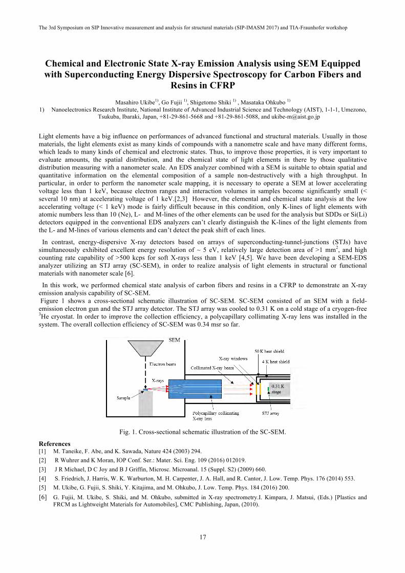
In this work, we performed chemical state analysis of carbon fibers and resins in a CFRP to demonstrate an X-ray emission analysis capability of SC-SEM. Figure 1 shows a cross-sectional schematic illustration of SC-SEM. SC-SEM consisted of an SEM with a field-emission electron gun and the STJ array detector. The STJ array was cooled to 0.31 K on a cold stage of a cryogen-free 3He cryostat. In order to improve the collection efficiency, a polycapillary collimating X-ray lens was installed in the system. The overall collection efficiency of SC-SEM was 0.34 msr so far.
Fig. 1. Cross-sectional schematic illustration of the SC-SEM.
References [1] M. Taneike, F. Abe, and K. Sawada, Nature 424 (2003) 294. [2] R Wuhrer and K Moran, IOP Conf. Ser.: Mater. Sci. Eng. 109 (2016) 012019. [3] J R Michael, D C Joy and B J Griffin, Microsc. Microanal. 15 (Suppl. S2) (2009) 660. [4] S. Friedrich, J. Harris, W. K. Warburton, M. H. Carpenter, J. A. Hall, and R. Cantor, J. Low. Temp. Phys. 176 (2014) 553. [5] M. Ukibe, G. Fujii, S. Shiki, Y. Kitajima, and M. Ohkubo, J. Low. Temp. Phys. 184 (2016) 200. [6] G. Fujii, M. Ukibe, S. Shiki, and M. Ohkubo, submitted in X-ray spectrometry.I. Kimpara, J. Matsui, (Eds.) [Plastics and
FRCM as Lightweight Materials for Automobiles], CMC Publishing, Japan, (2010).

The 3rd Symposium on SIP Innovative measurement and analysis for structural materials (SIP-IMASM 2017) and TIA-Fraunhofer workshop
18
Development of In Situ High-Temperature Transmission Electron Microscopy at the University of Tsukuba in SIP-IMASM Project
Manabu Tezura1), K. Murakami1), Takuya Okamoto1), Hideki Kobayashi1), Shogo Kikuchi1), Tomo-o Terasawa1, 2), and Tokushi
Kizuka1) † 2) Division of Materials Science, Faculty of Pure and Applied Sciences, University of Tsukuba
(1-1-1, Tennoudai, Tsukuba, Ibaraki 305-8573, Japan) 1) Present address: Institute of Materials and Systems for Sustainability, Nagoya University
(Furocho, Chikusa, Nagoya, Aichi 464-8603, Japan)
†E-mail: [email protected]
High-resolution transmission electron microscopy (TEM) provides all the kinds of information on the atomistic dynamics of microstructures, i.e., crystal structures, textures, compositions, surfaces, interfaces, grain boundaries, and point defects. Thus, high-resolution TEM has contributed to the progress of materials science since this method was invented by Max Knoll and Ernst August Friedrich Ruska in 1931. Soon after the invention, in situ TEM was developed. This is because in situ TEM enables the analysis of the microstructural dynamics in various environments in which materials are actually used; in situ TEM is more useful for study and development of materials.
High-temperature environments are subjects to advanced structural materials, which are the target materials of SIP, e.g., heat-resistant structural metals and alloys, and thermal barrier coatings using in jet engines. Various types of sample heating stages for in situ TEM have been developed by many TEM researchers. The structural dynamics relating to texture control, e.g., recrystallization, phase transition, precipitation, and dislocation movement, have been investigated, resulting in the feedback of material designs. However, the typical maximum temperature of commercial heating stages has still been limited under 1200 K, which is at least 500 K lower than the temperatures required for the studies of recent advanced heat-resistant structural materials, such as jet engine and aircraft materials. In this project, SIP – Innovative Measurement and Analysis for Structural Materials (SIP-IMASM), the authors first jacked up the maximum temperature of the high-temperature stage for TEM to 1300 K by designing a new type of the stage structure imposing no restrictions for specular sample shapes, i.e., the stage can be used for bulk materials in addition to nanometer-sized isolated nanostructures, such as particles, fibers, and thin films, as reported in the 1st Symposium on SIP-IMASM 2015 [1]. The authors have taken over the challenge and have made various improvements of the previous heating system, e.g., the choice of heater materials and shapes, the mounting techniques of the heater, the purpose-built power cable assemble, and the dedicated power supply system. As a result, we have achieved the possible heating temperature up to 2000 K [2–7], which is the maximum temperature of the heating stage of TEM that have been already constructed. In this presentation, we report the development process of the in situ high-temperature high-resolution TEM and the application to heat-resistant structural materials.
Some of the authors collaborate with Professor Masao Kimura of KEK for the high temperature experiments of heat resistant ceramics coating [7]. This study was supported by Cross-Ministerial Strategic Innovation Promotion Program – Unit D66 – Innovative measurement and analysis for structural materials.
References [1] Tomo-o Terasawa and Tokushi Kizuka, the 1st Symposium on SIP-IMASM 2015.
[2] Tokushi Kizuka, Shogo Kikuchi, Manabu Tezura, and Tomo-o Terasawa, the 2nd Symposium on SIP-IMASM 2016. [3] Tomo-o Terasawa, Shogo Kikuchi, Manabu Tezura, and Tokushi Kizuka, J. Nanosci. Nanotechnol. 17, 2848 (2017).
[4] Tokushi Kizuka and Shin Ashida, Sci. Rep. 5, 13529 (2015). [5] Manabu Tezura and Tokushi Kizuka, Sci. Rep. 6, 29708 (2016).
[6] Kohei Yamada and Tokushi Kizuka, Sci. Rep. 7, 42901 (2017).
[7] Shogo Kikuchi, Manabu Tezura, Masao Kimura, and Tokushi Kizuka, in this Symposium (the 3rd Symposium on SIP-IMASM 2017)

The 3rd Symposium on SIP Innovative measurement and analysis for structural materials (SIP-IMASM 2017) and TIA-Fraunhofer workshop
19
Keynote 3
Bernd Valeske

The 3rd Symposium on SIP Innovative measurement and analysis for structural materials (SIP-IMASM 2017) and TIA-Fraunhofer workshop
20
Nondestructive Characterization and Quality Control of Lightweight Materials and Assemblies (Advanced Joining Technologies) - R&D and Applications in
Automotive and Transport Industry
Bernd Valeske Vice Director, Fraunhofer Institute for Nondestructive Testing IZFP, Saarbruecken (Germany)
Today, a broad variety of innovative lightweight and hybrid materials are being developed in order to fulfill the growing requirements for high performance-parts and components in automotive and transport industry, including railway and aircraft applications. Thereby, on the one hand optimum (structural) performance with regard to the desired technical functions for high-demanding operational issues is required and must be guaranteed, whereas on the other hand, these material properties are to be generated by an overall cost-effective production at the best price, i.e. in order to manufacture high-quality products. In addition, during the last few years the acquisition and analysis (i.e. processing and evaluation) of digital data has become on of the most relevant issues for industry (i.e. process of digital transformation). The digital information (or digital product memory) is supposed to be the basic prerequisite and a key element for optimization strategies of any kind of technical processes in the industry of the future. This is why the strategy for future NDT and NDE is to build up a digital product memory (or industrial data space) consisting of smart materials data that are covering the entire life cycle of products with all its stages from “birth of a material” over “production and assembly processes of components” until “end of life”. The presentation gives an overview on the strategy of advanced nondestructive sensor principles for data acquisition and on data evaluation procedures regarding a holistic approach in life-cycle monitoring with the objective of optimizing new materials as well as new product and process developments. Examples of industrial prototype systems are shown for advanced nondestructive data acquisition and data evaluation methods. Their implementation into modern ndt technologies for automated process control in the production line is presented. Applications are comprising lightweight components or parts and the corresponding manufacturing processes in automotive and transport industry, e.g. process control and in-line inspection systems for press-hardened ultrahigh-strength steels, for aluminium and some super alloy processing, for cutting-edge joining technologies in new and mixed material design (like structural adhesive bonding, mechanical joining, laser welding process, etc.).

The 3rd Symposium on SIP Innovative measurement and analysis for structural materials (SIP-IMASM 2017) and TIA-Fraunhofer workshop
21
Advanced analytical technologies for multi-materials: An initiative at NISSAN ARC
Hideto Imai1), Takanori Itoh 1), Takashi Matsumoto 1) 1) Device-functional analysis department, NISSAN ARC Ltd. ( 1 Natsushima, Yokosuka, 237-0061, JAPAN)
E-mail:[email protected]
For establishing light-weight concepts for automotive or other transport industry, technologies regarding with innovative structural materials and their hetero-junctions to promote so-called “multi-materials”, are now developing in world-wide. Materials design in nanoscales to maximize the capability of the materials to their limit, and multi-materials design to create new functions or to optimize them to gain superior performance by integrating materials by the choosing the right materials in right place, are main targets for the concept.
Functions and performances of multi-materials are, however, not simply determined by properties of individual components: their properties and performance is determined as a result of mutual interactions of components, including their nanostructured interfaces, in true operating condition. Thus, there is an increasing demand for establishing new advanced analytical technologies to connect “structures and properties” in such advanced materials and in their multi-materials.
NISSAN ARC Ltd. has been tackling with establishing an integrated analytical system for complicated multi-materials to satisfy such rising requirements, by combining advanced analytical technologies, such as synchrotron radiation x-ray, neutrons, state-of-the-art electron microscopy, scanning probe microscopy, and large-scale computational theoretical simulations. [1-3] We aim to understand the relationship between structure and function in multi-materials through structure analyses utilizing diffraction, scattering, and spectroscopy, and property-mapping combined with such structure analyses and imaging techniques.
Representative results on interface structure analysis on hetero-junction, by synchrotron radiation x-rays, comprehensive analysis on nanocomposite materials by synchrotron radiation x-rays, electron microscopy, scanning probe microscopy, and non-destructive structural property mapping with Bragg-edge imaging technique with neutron beams, will be introduced.
References
[1] A. Hirata, S. Kohara, T. Asada, M. Arao, C. Yogi, H. Imai, Y. Tan, T. Fujita, M. Chen, “Atomic-scale disproportionation inamorphous silicon monoxide”, Nat. Commun., 7, 11591 (2016)[2] K. Kubobuchi, M. Mogi, M. Matsumoto, T. Baba, C. Yogi, C. Sato, T. Yamamoto, T. Mizoguchi, H. Imai, “A valence stateevaluation of a positive electrode material in an Li-ion battery with first-principles K- and L-edge XANES spectral simulations andresonance photoelectron spectroscopy”,J. Appl. Phys. , 120, 142125 (2016).[3] T. Phakkeeree, Y. Ikeda, H. Yokohama, P. Phinyocheep, R. Kitano, A. Kato, “Network-like structure of Lignin in Natural RubberMatrix to form high performance elastomeric bio-composite”, J. Fiber. Sci. Technol. 72, 160 (2016)

The 3rd Symposium on SIP Innovative measurement and analysis for structural materials (SIP-IMASM 2017) and TIA-Fraunhofer workshop
22
Chemical state mapping of barrier coating using a newly-developed XAFS-CT
Y. Takeichi 1,2), Y. Niwa 1), T. Watanabe 1), S. Kitaoka 3), M. Kimura 1,2) 1) Institute of Materials Structure Science, High Energy Accelerator Research Organization (KEK)
1-1 Oho, Tsukuba, 305-0801 Japan TEL +81-29-864-1171, E-mail: [email protected] 2) School of High Energy Accelerator Science, SOKENDAI, 1-1 Oho, Tsukuba, 305-0801 Japan
3) Japan Fine Ceramics Center, 2-4-1 Mutsuno, Atsuta-ku, Nagoya, 456-8587 Japan
Thermal barrier coatings (TBC) and environmental barrier coatings (EBC) are known to play an important role in enhancing the operating temperatures of gas-turbine engines [1]. Microstructures of chemical and crystallographic properties of TBCs and EBCs provide suggestive information about spallation and failure mechanism, and then the durability of these materials. Synchrotron-based XRD analysis was reported to be a powerful tool to analyse the crystallographic properties of TBCs [2]. In the chemical properties, on the other hand, a coating material undergoes various chemical reactions caused by oxygen, water vapor and other chemicals in the high-temperature combustion exhausts. Therefore, investigating the chemical properties in the microscopic scales is also important to understand the degradation of TBCs and EBCs. We have reported 3D observation of TBCs using laboratory-source-based X-ray CT [3]. Here we report a result showing the 3D distribution of the chemical properties of ytterbium silicate, a top-coat material of the EBCs.
A XAFS-CT instrument, an X-ray computed tomography observation combined with X-ray absorption fine structure, was newly developed at PF-AR NW2A beamline in KEK, Japan. The spatial resolution of ~20 nm in the 2D observation using a Fresnel zone plate was confirmed. It took about 20 minutes to take a single synchrotron-based tomography of 360 projections. XAFS-CT observation can be performed in the photon energy range of 5–11 keV, including K-edges of 3d transition metal elements and L-edges of rare-earth elements.
The sample, a Yb2Si2O7 wafer was treated under the oxygen partial pressure gradient at 1600 °C. A specimen for the CT observation was cut out from the surface of the wafer. The X-ray energy was tuned at around Yb L3-edge to obtain XAFS-CT dataset. The tomography datasets at 32 energy points were reconstructed and analysed using TXM Wizard software package [4].
Figure 1(a) shows a ytterbium L3-edge jump map of a slice in the 3D dataset of XAFS-CT observation. The micropores and highly absorbing grains inside the ceramic were clearly visualized. X-ray absorption spectra of the grains and the other area were successfully exploited as shown in Fig. 1(b). Chemical states of Yb in the both regions were found to be trivalent, and we conclude the highly absorbing micrograins were Yb2SiO5 formed by oxygen treatment. This was also confirmed by a bulk X-ray diffraction experiment on this wafer.
(a)
(b) 1.0
0.8
0.6
0.4
Abs
orpt
ion
(arb
. uni
ts)
9040900089608920Photon energy (eV)
ROI_low ROI_high
Fig. 1. (a) Ytterbium L3-edge jump map of a slice in the reconstructed 3D dataset of XAFS-CT observation. (b) X-ray absorption spectra of the low and high absorption regions in (a).
Acknowledgement This work was supported by the Structural Materials for Innovation of the Cross-ministerial Strategic Innovation
Promotion Program (SIP) of Japan Science and Technology (JST). Experiments using synchrotron radiation were performed with the approval of the Photon Factory Program Advisory Committee (Proposal Nos. 2015S2-002 and 2016S2-001).
References [1] D. R. Clarke and C. G. Levi, Annu. Rev. Mater. Res., 33, 383 (2003). [2] J. Almer, U. Lienert, R. L. Peng, C. Schlauer, and M. Odén, J. Appl. Phys., 94, 697 (2003). [3] Y. Takeichi, in the 2nd Symposium on SIP Innovative measurement and analysis for structural materials (SIP-IMASM2016). [4] Y. Liu, F. Meirer, P. A. Williams, J. Wang, J. C. Andrews, and P. Pianetta, J. Synchrotron Rad., 19, 281 (2012).

The 3rd Symposium on SIP Innovative measurement and analysis for structural materials (SIP-IMASM 2017) and TIA-Fraunhofer workshop
23
Multiscale Characterization of Advanced Ceramics and Alloys in Aerospace Applications
Hiroaki MAMIYA1) and Toru HARA1) 1) National Institute for Materials Science (NIMS)
1-2-1 Sengen, Tsukuba, 305-0047 Ibaraki, JapanTel: +81-29-859-2755, Fax: +81-29-859-2801
e-mail: [email protected]
Full understanding of the relationship between structures and properties of structural materials used in aerospace applications is a key to further improve their performance. Especially, in practical materials, such structures are usually complicated, hierarchical, and heterogeneous, evolve during manufacturing and operation, and are, sometimes unexpectedly, correlated with the mechanical properties on each scale. Therefore, it is highly required to establish multilateral and comprehensive analysis approaches for the evolution of structures/properties in structural materials in their overall life cycle without preconceived idea, in order to promote the advances in aircraft engines, airframes and thermal power generation. For this reason, we develop characterization methodology for integration of operando, multiscale, and multi-probe analyses on structure materials, with optimally combining the research resources of NIMS and the open innovation hub, TIA (see Figure.) In this talk, some topics of this study will be presented.
Fig. 1. Scheme of our integrated analyses on structural materials.
Correlative microscopy on hierarchical structures using LM/SEM/TEM
In this method, morphology of a sample is observed by optical microscopy and SEM, then target region is picked up and sliced for 3D observation. After serial sectioning, a final fragment is observed by a transmission mode in the FIB-SEM. All these observations can be performed in one apparatus. In combination with following TEM observation, we have succeeded to obtain many kinds of information such as surface condition, void structure from 3D observation, compositional and crystal orientation information, etc. from the same peace simultaneously [1]. In this paper, achievements of the study on ceramics fibers are demonstrated.
Contrast variation analyses on heterogeneous structures by complementary use of SAXS/SANS Using X-ray and neutron scattering complementarily, we derive information on chemical composition of nano-structural components as well as on their number density and size from the intensity ratio of SAXS to SANS. In this paper, we demonstrate the application of this analysis to a heat resistant alloy [2].
References [1] T. Hara, “3D microstructure observation of materials by meaans of FIB-SEM serial sectioning.” KENBIKYO, 49, 53-58 (2014).[2] A. Kowalska-Mori, H. Mamiya at al., “Manufacturing and characterization of Ni-free N-containing ODS austenitic alloys,”Materials Characterization, submitted.

The 3rd Symposium on SIP Innovative measurement and analysis for structural materials (SIP-IMASM 2017) and TIA-Fraunhofer workshop
24
Microstructure characterization of structural materials by laser assisted 3D atom probe
Taisuke Sasaki, M.-Z. Bian, Tadakatsu Ohkubo, Kazuhiro Hono Research Center for Magnetic and Spintronic Materials,
National Institute for Materials Science, 1-2-1 Sengen, Tsukuba, Ibaraki, Japan Email: [email protected]
3D atom probe (3DAP) can map out the elemental distribution in 3 dimension with high special resolution, and is
useful to analyze nano-/atomic-scale microstructure features that critically affects the properties, e.g. the nanoscale precipitates and the elemental segregation at the interface and along the dislocations, in inorganic materials such as metallic materials, ceramic materials and semiconductors etc.. 3DAP also offers extensive capabilities for the chemical composition measurements at the atomic scale, which is rather difficult in elemental analysis by energy dispersive spectroscopy (EDS) and electron energy loss spectroscopy (EELS) in transmission electron microscopy (TEM). This presentation introduces how the 3D atom probe can be used to analyze the nanoscale precipitates and elemental segregation along the grain boundaries by taking magnesium based alloys and Nd-Fe-B magnet as examples, and present the microstructure evolution in near-a titanium alloy for high temperature application.
1. Characterization of monoatomic layer precipitates in magnesium based alloy Recent intense interest in developing lighter wrought alloys revived researches on precipitation hardenable
magnesium alloys. Since the age-hardening responses of commercially available magnesium alloys are poor, precipitation hardening has not been used in conventional wrought magnesium alloys. However, optimizations of alloy compositions often lead to the formation of metastable nano-sized precipitates during artificial aging, which substantially enhances the yield strength. The trace addition of Zn into Mg-0.3 at.%Ca alloy results in the formation of monoatomic layer Guinier Preston (G.P.) zone as shown in high-angle annular dark field scanning TEM (HAADF-STEM) image with ~5 nm in diameter. 3DAP analysis shows that Zn and Ca are enriched in the G.P. zones. Based on the detailed analysis by TEM and 3DAP, structure and chemical composition of the G.P. zone is determined, and the impact of the G.P. zone dispersion on the mechanical property is discussed.
2. Microstructure evolution in near-a Ti alloy To meet the strong demands for improving the efficiency of the aircraft engines, heat resistant and lightweight alloys
with high specific strength are required. Near-a titanium (Ti) alloy is a promising material in these applications mainly because of the high specific strength and satisfactory creep resistance at temperatures up to 660 oC. However, one common issue in the near-a titanium (Ti) alloys is that the fracture toughness and low cycle fatigue property are deteriorated by the precipitation of a2 phase during high temperature exposure while the a2 phase is also used to increase the strength.
In this work, we have analysed the precipitates by TEM and 3DAP and clarified the how the microstructure changes during heat treatment in a near-a Ti alloy to suggest guidelines to improve the fracture toughness and low cycle fatigue properties.
Figure: (a) low magnification and (b) atomic-resolution HAADF-STEM image obtained from artificially aged Mg-0.3Ca -0.6Zn alloy. (c) is the structural model of the G.P. zones constructed based on the HAADF-STEM image, and (d) is the 3D atom map obtained from the G.P, zones.

The 3rd Symposium on SIP Innovative measurement and analysis for structural materials (SIP-IMASM 2017) and TIA-Fraunhofer workshop
25
Sample Size Effect on Electrodeposited Sub-10 nm Nanocrystalline Nickel and possible application to CFRP
Takashi Nagoshi1), Masahide Mutoh2), Tso-Fu Mark Chang 2), Masato Sone 2) 1) National Institute of Advanced Industrial Science and Technology, Namiki 1-2-1, Ibaraki, Japan
Tel: +81 29 861 8286, E-mail:[email protected] 2) Tokyo Institute of Technology, Japan
The size effect known as the mechanical properties changes by the varying sample size below several tens of microns had been extensively studied [1]. Understanding of the nature of sample size effect can shed light on the deformation mechanisms and also in the practical use through MEMS applications. However, most of the studies of sample size effect had used single crystal metals without any structure inside samples and only few deals with the effect of internal structures such as grain boundary [2]. Especially the sample size effect on the nanocrystalline metals had been under controversy including the existence of it. Considering the potentials of nanocrystalline metals with its high strength, investigations of sample size effect on the nanocrystalline metals is very important. The measurement method using micro pillars for compression is beneficial for the investigation of local mechanical properties. Nanocrystalline nickel was electrodeposited with the emulsified electrolyte and supercritical carbon dioxide. Emulsions was formed by stirring the electrolyte with poly oxyethylene lauryl ether (C12H25(OCH2CH2)15OH) under high pressure (15Mpa) of supercritical carbon dioxide. Plated nanocrystalline nickel and single crystal nickel purchased from Nilaco Inc. was used to fabricate compression pillars. To avoid tapering of FIB milling, perpendicular beam had been used to fabricate square cross section pillars with side length ranging from 5 µm to 30 µm. Micro-compression testing was conducted by custom-made testing machine with flat ended diamond indenter with strain rate of 2.5x10⁻³. Deposited nanocrystalline nickel had 7.7 nm of average grain size measured by using TEM. Pillars of single crystal nickel (SCNi) with compression axis along <789> crystal orientation as analysed by EBSD and nanocrystalline nickel (NCNi) were compression tested and the results shown in Fig (a) and (b). SCNi has very low yield stress of 10 to 20 Mpa which agrees well with the reported critical resolved shear stress of nickel. After yielding, large work hardening due to the cross slip of dislocations while several slip systems can be operative in compressions of near [111] orientation. And finally work softened by the macroscopic shear formation. Compression tests of NCNi were shown in true plastic strain starting from 0.2% offset stress as yield stress which more than 10 times higher than that of SCNi. The deformation process is believed to be a grain boundary process, such as grain boundary sliding or grain rotation. Every stresses, 1% flow stress and yield stress of NCNi and yield stress of SCNi were plotted against the sample size in double logarithmic scale in Fig. 1a. The stress dependence on sample size were negative which means smaller is stronger in both single crystal and nanocrystalline nickel. Although the scaling exponent of -0.125 for NCNi was very small compared with SCNi, strength increased from 2.5 to 3.1 Gpa when the pillar size was decreased from 30 to 5 µm. The size effect in the present NCNi can be considered as a result of grain boundary sliding, which is reported to involve several grains in formation of micro shear band along the grain boundaries known as cooperative grain boundary sliding (CGBS) [3].CGBS events could initiate from flat segment of grain boundaries and the number of these segments decreased when sample size becomes smaller. Increase in strength with decreased sample size is the consequence of decreased shear areas in the operation of CGBS. Local mechanical property evaluations could address the sample size effect of nanocrystalline metals. This method can also be used for the evaluations of joint interface of CFRP used for automobile or aircraft.
Fig. 1. Results of micro-compression tests. (a) SCNi, (b) NCNi, and (c) sample size dependence of stresses.
References [1] J.R. Greer, J.T.M De Hosson, Prog. Mater. Sci. 56 (2011) 654 [2] D. Jang, J.R. Greer, Scripta Mater., 64 (2011) 77. [3] M. G. Zelin and A. K. Mukherjee, Acta Metall. Mater., 43 (1995) 2359.

The 3rd Symposium on SIP Innovative measurement and analysis for structural materials (SIP-IMASM 2017) and TIA-Fraunhofer workshop
26
Beam Focusing Characteristics and Elemental Mapping Using the Ion Microbeam System on the 6 MV Tandem Accelerator
at the University of Tsukuba
A. Yamazaki1), K. Sasa1,2), S. Ishii2), M. Kurosawa3), S. Tomita1), H. Naramoto2), M. Sataka2), H. Kudo2), S. Shiki4), M. Ohkubo4), A. Uedono1,2)
1) Faculty of Pure and Applied Sciences, University of Tsukuba, 1-1-1 Tennodai, Tsukuba, Ibaraki 305-8571, Japan phone: +81-29-853-2498, fax: +81-29-853-2565,
E-mail: [email protected] 2) Research Facility Center for Science and Technology, University of Tsukuba,
1-1-1 Tennodai, Tsukuba, Ibaraki 305-8577, Japan 3) Faculty of Life and Environmental Sciences, University of Tsukuba,
1-1-1 Tennodai, Tsukuba, Ibaraki 305-8572, Japan 4) National Institute of Advanced Industrial Science and Technology (AIST),
1-1-1 Umezono, Tsukuba, Ibaraki 305-8568, Japan
An ion microbeam system has been constructed in 2016 at the accelerator facility in the University of Tsukuba [1]. Figure 1 shows the schematic view of the present ion microbeam line at the 6 MV tandem accelerator facility. The microbeam equipment is supplied by the Oxford Microbeams Ltd. It consists of two beam defining slits, two-dimensional scanning coils, magnetic quadrupole triplet lens for beam focusing. The distance from the object slit (shown as the first slit in the Fig. 1) to the target position is 8730 mm, and the working distance is 180 mm. This ion microbeam system will be mainly used for X-ray imaging of two dimensional distributions of light elements in structural materials using particle induced X-ray emission (PIXE) technique. A silicon drift detector (SDD) with a thin window of Si3N4 has been installed for detecting characteristic X-rays emitted from light elements such as boron, carbon, and nitrogen, which are commonly used as additive elements in structural materials. In addition, a superconducting tunnel junction (STJ) array detector [2, 3] is going to be installed to perform PIXE for light elements more efficiently. A new large target chamber has been fabricated and installed in the fall of 2016. This new chamber is designed for multi-purpose analysis; to utilize not only an SDD and an STJ detector but also a BGO detector used for nuclear reaction analysis (NRA) and a silicon surface barrier detector used for elastic recoil detection analysis (ERDA) to observe hydrogen in structural material.
Ion beam focusing tests are proceeding. The diameter of the focused ion beam is evaluated from the scanning transmission ion microscope (STIM) image of copper fine grid, and a focused proton beam of 2 µm in diameter was obtained up to now. Some results of multi-elemental mapping will be presented at the conference.
Fig. 1. Schematic view of the ion microbeam line at the 6 MV tandem accelerator facility.
References [1] A. Yamazaki, K. Sasa, S. Ishii, M. Kurosawa, S. Tomita, S. Shiki, G. Fujii, M. Ukibe, M. Ohkubo, A. Uedono, E. Kita,
“Development of a microbeam PIXE system for additive light elements in structural materials”, Nucl. Instrum. Methods B 404, 92-95 (2017)
[2] M. Ukibe, S. Shiki, Y. Kitajima, M. Ohkubo, Fabrication of superconducting tunnel junctions for soft X-ray spectroscopy, X-ray Spectrom., 40, 297 (2011).
[3] S. Shiki, M. Ukibe, Y. Kitajima, M. Ohkubo, X-ray detection performance of 100-pixel superconducting tunnel junction array detector in the soft X-ray region, J. Low Temp. Phys., 167, 748 (2012).

The 3rd Symposium on SIP Innovative measurement and analysis for structural materials (SIP-IMASM 2017) and TIA-Fraunhofer workshop
27
In situ XAFS/XRD simultaneous measurement of barrier coating up to 1500 °C
K. Kimijima1), 2), Y. Takeichi1), 2), Y. Niwa1), M. Kimura1), 2) 1) Institute of Materials Structure Science, High Energy Accelerator Research Organization (KEK)
1-1 Oho, Tsukuba-shi, 305-0801 JAPAN TEL +81-29-864-5200 (ex. 2547), E-mail: [email protected]
2) School of High Energy Accelerator Science, SOKENDAI, 1-1 Oho, Tsukuba-shi, 305-0801 JAPAN
In order to increase the energy efficiency of gas turbine engines used in aircrafts, it is necessary to operate at a temperature higher than the current temperature. Evaluate methods of the properties of structural materials used at ultrahigh temperatures such as gas turbine blades of engines are required, and it is essential to have a technique to accurately measure changes in structure and chemical state proceeding under these conditions. Thus, in situ measurement technique at ultra-high temperature is required. As various type of reactions, such as diffusion of main component, phase transition, and precipitation of minor phases, are expected, the combination of complemental analytical techniques are inevitable. Considering these requirements, we are developing a technology to measure simultaneously a short-range structure obtained by XAFS and a long-range structure obtained by diffraction measurement at ultra-high temperature up to 1500 °C. We have developed a prototype in situ furnace to investigate elemental technologies for spectroscopic measurements at extremely high temperatures, and have been accumulating XAFS measurement techniques at high temperatures [1]. Here we report the development of the in situ the furnace for spectroscopic / diffraction measurement and typical results of XAFS / XRD measurements.
The XAFS / XRD simultaneous measurement furnace was developed based on an infrared furnace (gold image furnace) which is not susceptible to properties of material such as a thermal conductivity of the sample as a heating method. In order to simulate the operating condition of an aircraft engine, we aimed at measurement at 1500 °C for regular use. The heating area in the cell is about 10 × 10 mm at the sample position, which is sufficiently larger than the X-ray beam irradiation area. Figure 1 shows photographs of the novel ultra-high temperature XAFS/XRD furnace under development, which is installed at the beam line of synchrotron facility. For heating experiments, a sintered plate of Yb2Si2O7 (8 × 8 mm, t = 0.5 mm) was used as a sample. Measurements of Yb LIII absorption edge (8944 eV) and diffraction (8046 eV) were carried out at KEK PF BL-15A1, at which semi-micro beam (about 20 µm) can be utilized. XAFS was measured by detecting the fluorescence from the sample with a silicon drift detector (SDD) from the direction of 90° with respect to the X-ray optical axis. For the XRD measurement, the required angular range was measured in multiple steps using PILATUS 100k installed in a goniometer. The camera length was 200 mm. The spot diameter of the irradiated X-ray beam on the sample was estimated to be about 0.2 (vertical) × 0.1 (horizontal) mm. This is because the beam spread in the lateral direction is deviated from the focal position, and the beam spread in the longitudinal direction is caused by tilting the specimen. Temperature rise was carried out under continuous air flow.
Fig. 1. Set-up of the measurement system at PF BL-15A1.
It became clear that there are technical problems to be improved regarding sample retention at high temperature and
measurement and control method of temperature. In the presentation, we will report the results of high temperature cycle XAFS / XRD measurement of Yb2Si2O7 and discuss future technical issues to be studied.
Acknowledgement This work was supported by SM4I, SIP of JST. Experiments using synchrotron radiation were performed with the approval of the Photon Factory at IMSS, KEK Program Advisory Committee (Proposal Nos. 2015S2-002 and 2016S2-001).
References [1] K. Kimijima, Y. Takeichi, Y. Niwa, K. Takahashi, and M. Kimura, 2nd SIP-IMASM, 57 (2016).

The 3rd Symposium on SIP Innovative measurement and analysis for structural materials (SIP-IMASM 2017) and TIA-Fraunhofer workshop
28
Keynote 4
Paolo Feraboli

The 3rd Symposium on SIP Innovative measurement and analysis for structural materials (SIP-IMASM 2017) and TIA-Fraunhofer workshop
29
Forged Composite as technology for the future
Paolo Feraboli, Ph.D. Director, Automobili Lamborghini ACSL
After working on the certification process of chopped prepreg material for the Boeing 787 program between 2006 and
2012, the Automobili Lamborghini ACSL, also known as Lambo Lab, developed a material/process/application of new generation of carbon fiber sheet molding compounds (CFSMC) known as Forged Composite technology. The Lambo Lab introduced Forged Composite in the Lamborghini Sesto Elemento technology demonstrator vehicle, for which it developed the main shell of the monocoque as well as all 8 wishbone suspension ams. Since then Lamborghini has introduced this technology on several other components, in particular on the Huracan line-up, including the JEC award-winning interior trim package, the new engine cover and active aerodynamic wing of the Performante version, and others. Forged Composite technology, if smartly utilized, can offer production cost advantages, structural performance, as well as unique esthetical appearance. However, key lies in fully understanding how to design and manufacture parts, which poses more challenges than traditional materials. Press-based composite technology, such as CFSMC, constitute the future of volume composite applications, because of the fast cycle time associated with both material placement and curing. They also offer unique capability in terms of complex three-dimensional architecture, notch insensitivity and thickness optimization. However, improvements in fiber and resin characteristics are still needed to increase stiffness and strength, reduce odor and emissions, and reduce cost.

The 3rd Symposium on SIP Innovative measurement and analysis for structural materials (SIP-IMASM 2017) and TIA-Fraunhofer workshop
30
Expectation of Measurement and analysis for Light Weight vehicles
Kiyoshiba Mase 1) TOYOTA MOTOR COPPORATION, 1, Toyota-cho, Toyota, Aichi, 471-8572, Japan
E-mail: [email protected]
From the climate change and regulations, we have to accelerate light weight development in automotive. Production methods including joining will be developed for new structure and multi materials. And more from the LCA view point, concerning recycle and CO2 reduction technique will be needed when aluminium and CFRP materials are applied.
In this presentation, resent Light Weight trends and development subject will be discussed, and express the expectation for state- of the-art measurement and analysis technique.

The 3rd Symposium on SIP Innovative measurement and analysis for structural materials (SIP-IMASM 2017) and TIA-Fraunhofer workshop
31
CFSMC technology as the future for high volume composite applications
Koichi Akiyama Paolo Feraboli, Ph.D. Bonnie Wade, Ph.D.
Akira Nakagoshi, GM Steve Wusterbarth
Gemini Composites LLC, a group company of Mitsubishi Chemical
A new generation of carbon fiber sheet molding compounds (CFSMC), also known as Forged Composite, can enable OEMs to obtain lightweight designs at lower cost and higher rate than prepreg and RTM technologies, while maintaining the necessary structural performance. The unique nature of CFSMC, which exhibits mechanical behavior very different from both aluminum and traditional CFRP, requires additional knowledge for the successful design of parts. This knowledge is critical in determining the success or the failure for introducing CFSMC technology with a customer. Gemini Composite LLC specializes in the design, engineering and prototyping of commercial products using Forged Composite technology. Keys to success are the characterization of the mechanical behavior of the material, and the ability to simulate it adequately. Factors that can dramatically influence the design include the material itself, the process, the geometry, and load distribution. Understanding of all these components is the only way to ensure success with such complex materials. Gemini products launched to date include Callaway Golf driver heads, and Union snowboard bindings, but other customer projects include a bicycle frame, a lacrosse head, and others. Mitsubishi Chemical, which today is the world’s largest producer of CFSMC by volume, has invested heavily toward the goal of supplying customers worldwide with a full turn-key solution that starts from the raw fiber and CFSMC material, goes through part design and engineering, and ends with part production. The acquisition of Gemini in March 2017 has been the first step toward this strategy.

The 3rd Symposium on SIP Innovative measurement and analysis for structural materials (SIP-IMASM 2017) and TIA-Fraunhofer workshop
32
Full-field Displacement and Strain Measurement by Moiré Technique and Its Practical Application
Shien Ri1), Qinghua Wang1), Masataka Ohkubo1), Motomichi Koyama2), Kaneaki Tsuzaki2) 1) National Institute of Advanced Industrial Science and Technology, 1-1-1 Umezono, Tsukuba Ibaraki 305-3568, Japan
2) Department of Mechanical Engineering, Kyushu University, 744 Motooka, Nishi-ku, Fukuoka 819-0395, Japan
As a nondestructive optical technique, the Moiré technique has attracted great attention and has been applied to deformation measurement of various materials and structures in recent years. Down-sampling a repeated grating image instead of overlaps two gratings, a clear Moiré fringe can be automatically generated by image processing because the CCD/CMOS sensors can be considered as a reference grating in Moiré technique. This method is called the sampling Moiré method [1], which can measurement displacement up to 1/1000 of a grating pitch. Whereas the DIC method works with a random pattern, the sampling Moiré method does just the opposite, reducing processing complexity by requiring the structure to incorporate a regular high-contrast grating pattern. This method is applicable at an atomic level as well as to electronic devices, mechanical components, and large structures among a wide application.
Based on the principle of the sampling Moiré method, repeated pattern can be used to measure the deformation of
various materials and structures at different scales. For a small-size specimen, a microscope (such as LSM, SEM, AFM, TEM, etc.) is a suitable grating observation apparatus. Recently, the full-field deformation measurement of a carbon fiber reinforced plastic (CFRP) specimen under three-point bending was successfully carried out. Besides, a two-dimensional Moiré phase analysis method was proposed to accurately measure the in-plane strain distributions even if the specimen grid is inclined at a large angle. By analyzing two-dimensional Moiré phase distributions simultaneously, the shear strain measurement accuracy can be remarkably improved [2]. As an application, the 2D micro-scale strain distributions of a titanium alloy were measured, and the crack occurrence location was successfully predicted from strain concentration [3]. In addition, we also apply the sampling Moiré method to large-scale structures such as high-temperature piping in a thermal power plant [4] or concrete or steel bridges.
In our study, a novel small-displacement measurement technique, the sampling Moiré method, can monitor the full-field displacement of ultra-small structures, including electronic devices and composite materials at nano/micro scale, as well as infrastructures such as bridge and high building at meter scale. Compared with conventional methods, the advantages of the sampling Moiré method are fast, automatic, highly accurate, strong anti-noise ability and large field of view with low-cost for full-field deformation measurements.
Fig. 1. Practical application of the deformation measurement by the sampling Moiré method
References [1] S. Ri, M. Fujigaki and Y. Morimoto, “Sampling moiré method for accurate small deformation distribution Measurement”, Exp.
Mech., 50(4), 501-508 (2010) [2] Q. Wang, S. Ri, H. Tsuda, M. Koyama and K. Tsuzaki, “Two-dimensional moiré phase analysis for accurate strain distribution
measurement and application in Crack Prediction”, Opt. Express 25(12), 13465-13480 (2017) [3] M. Koyama, K. Yamanouchi, Q. Wang, S. Ri, Y. Tanaka, Y. Hamano, S. Yamasaki, M. Mitsuhara, M. Ohkubo and K. Tsuzaki,
“Multiscale in situ deformation experiments: A sequential process form strain locaalization to failure in a laminated Ti-6Al-4V allloy”, Mat. Characterization, 128, 217-225 (2017)
[4] S. Ri, M. Saka, K. Nanbara and D. Kobayashi, “Dynamic thermal deformation measurement of large-scale, high-temperature piping in thermal power plants utilizing the sampling moiré method and grating magnets", Exp. Mech., 53(9), 1635-1646 (2013)

The 3rd Symposium on SIP Innovative measurement and analysis for structural materials (SIP-IMASM 2017) and TIA-Fraunhofer workshop
33
Poster papers
IMASM

The 3rd Symposium on SIP Innovative measurement and analysis for structural materials (SIP-IMASM 2017) and TIA-Fraunhofer workshop
34
High-Resolution Transmission Electron Microscopy of Interfaces in Carbon Fiber Reinforced Plastics
Manabu Tezura1), Koichi Murakami1), Kiyomi Nakajima2), Yasuhiro Horiike3), and Tokushi Kizuka1) † 1) Division of Materials Science, Faculty of Pure and Applied Sciences, University of Tsukuba
(1–1–1, Tennoudai, Tsukuba, Ibaraki 305-8573, Japan) 2) Academic Service Office for the Pure and Applied Sciences Area, University of Tsukuba
(1–1–1, Tennoudai, Tsukuba, Ibaraki 305-8577, Japan) 3) Faculty of Pure and Applied Sciences, University of Tsukuba
(1–1–1, Tennoudai, Tsukuba, Ibaraki 305-8577, Japan) †E-mail: [email protected]
The mechanical properties of composite materials, e.g., fracture, elasticity, and strength, are governed by the structure and characteristics of the interfaces between main composing elements. In the case of carbon fiber reinforced plastics (CFRP), the corresponding elements are carbon fibers and resin matrices, and thus the mechanical properties are influenced by various atomistic contact features of the interfaces, e.g., the adhesion of the matrices to the fibers, the distribution of void type defects, precipitation, and chemical variation. Transmission electron microscopy (TEM) provides all the kinds of the information of microstructures of various solid materials, i.e., crystal structures, textures, compositions, surfaces, interfaces, grain boundaries, and point defects. In particular, since interfaces are internal planar defects having a thickness of several atoms, their structures can be investigated only by a transmission-type real-space localized structure analysis method with atomistic spatial resolutions, i.e., high-resolution TEM. Thus, in this study, we have attempted to investigate the interfaces of CFRP using high-resolution TEM and related methods. In particular, we have tried to analyze the mechanical properties of CFRP using the in situ high-resolution TEM employing a picometer-precision dual-goniometer nanomanipulation system that has been developed by some of the present authors at the University of Tsukuba [1–5].
Master samples of CFRP were prepared by and provided from Epoxy Resin Materials Center Research & Development Division, NIPPON STEEL & SUMIKIN CHEMICAL CO., LTD. The samples were cut and milled mechanically to observe the interface cross section of the fibers and the resins and were thinned using an ion beam sputtering method. One of the samples for microscopic examination was mounted on the sample holder for the in situ high-resolution TEM. The sample holder was then inserted into the transmission electron microscope for dynamic atomistic observation at the University of Tsukuba (JEOL JEM-2011KZ-Custom) using an accelerating voltage of 200 kV. The sample chamber of the microscope was evacuated, first by a turbomolecular pump and then by an ion pump, resulting in a vacuum of 1 × 10⁻⁵ Pa. The sample inside the microscope was monitored using an originally designed optical microscope attached to the column of the microscope. The texture was observed with a direct magnification of higher than x500,000 by lattice imaging of high-resolution TEM using a video capture system. We could successfully observe the interface characteristics, i.e., the adhesion features of the matrices to the fibers, the distribution of void type defects, and precipitation at the atomic scale.
The authors thank Epoxy Resin Materials Center Research & Development Division, NIPPON STEEL & SUMIKIN CHEMICAL CO., LTD. for providing master samples of CFRP. This study was supported by Cross-Ministerial Strategic Innovation Promotion Program – Unit D66 – Innovative measurement and analysis for structural materials.
References [1] Tokushi Kizuka, Shogo Kikuchi, Manabu Tezura, and Tomo-o Terasawa, the 2nd Symposium on SIP-IMASM 2016. [2] Tomo-o Terasawa, Shogo Kikuchi, Manabu Tezura, and Tokushi Kizuka, J. Nanosci. Nanotechnol. 17, 2848 (2017).
[3] Tokushi Kizuka and Shin Ashida, Sci. Rep. 5, 13529 (2015). [4] Manabu Tezura and Tokushi Kizuka, Sci. Rep. 6, 29708 (2016).
[5] Kohei Yamada and Tokushi Kizuka, Sci. Rep. 7, 42901 (2017).

The 3rd Symposium on SIP Innovative measurement and analysis for structural materials (SIP-IMASM 2017) and TIA-Fraunhofer workshop
35
Effect of Free-Volume Holes on Dynamic Mechanical Parameters of Epoxy Resins for CFRP Studied by Positron Annihilation and PVT Experiments
H. J. Zhang1), S. Sellaiyan1), T. Sako1), A. Uedono1), Y. Taniguchi2), K. Hayashi2)
1)Division of Applied Physics, Faculty of Pure and Applied Science, University of Tsukuba, Tsukuba, Ibaraki 305-8573, Japan 2)Epoxy Resin Materials Center, Nippon Steel & Sumikin Chemical Co. Ltd., Kitasode 11-5, Sodegaura, Chiba 299-0266, Japan
We studied the relationship between dynamic mechanical properties and free-volume holes by positron annihilation lifetime (PAL) and pressure-volume-temperature (PVT) experiments for four types of amine-cured epoxy resins with different chemical structures.[1-3] Dynamic mechanical analysis (DMA) measurements were performed to investigate the temperature dependences of the four dynamic mechanical parameters of storage modulus E', loss modulus E'', damping factor tanδ, and complex viscosity |η*|. The PAL and PVT experiments were carried out to determine the free-volume hole properties of each sample. The correlations between the four dynamic mechanical parameters and hole fraction were studied by using the Williams-Landel-Ferry equation. In the temperature range of Tg(PAL)<T<Tg(PAL)+100 ◦C (Tg(PAL) is the glass transition temperature given by PAL experiments), the DMA and PAL experimental results exhibit regular variations of dynamic mechanical parameters with increasing relative hole fraction (1-hPAL@Tr/hPAL, where hPAL@Tr is the hPAL at the reference temperature Tr): (1) log[E'(T)] and log[|η*|(T)] decrease linearly in the temperature range of Tg(PAL)<T<Trub(E') (Trub(E') is the lowest temperature where E'(T) curve coincides with its fitting line in the rubbery status stage) and then remain nearly unchanged at Trub(E')<T<Tg(PAL)+100 ◦C; (2) log[E''(T)] increases linearly at Tg(PAL)<T<Tg(E''max) (Tg(E''max) is the temperature of maximum E'') and then decrease linearly at Tg(E''max)<T<Tg(PAL)+100 ◦C; (3) log[tanδ(T)] increase linearly at Tg(PAL)<T<Tg(tanδmax) (Tg(tanδmax) is the temperature of maximum tanδ) and then decrease linearly at Tg(tanδmax)<T<Tg(PAL)+100 ◦C. [4] In the temperature range of Tg(PVT)<T<Tg(PVT)+100 ◦C (Tg(PVT) is the glass transition temperature at atmospheric pressure given by PVT experiments), regular variations of dynamic mechanical parameters were observed with increasing relative hole fraction (1-hPVT@Tr/hPVT, where hPVT@Tr is the hPVT at the reference temperature Tr): (1) log[E'(T)] and log[|η*|(T)] decrease linearly in the temperature range of Tg(PVT)<T<Trub(E') and then remain nearly unchanged at Trub(E')<T<Tg(PVT)+100 ◦C; (2) log[E''(T)] increases linearly at Tg(PVT)<T<Tg(E''max) and then decrease linearly at Tg(E''max)<T<Tg(PVT)+100 ◦C; (3) log[tanδ(T)] increase linearly at Tg(PVT)<T<Tg(tanδmax) and then decrease linearly at Tg(tanδmax)<T<Tg(PVT)+100 ◦C. From these experimental results, both PAL and PVT techniques are evidenced to be reliable experimental approaches to quantitatively determine the free-volume hole fractions of polymers.
0.0 0.1 0.2 0.3
-3
0
6
9
0.0 0.1 0.2 0.3
6
7
8
9
Tg(E''max) E3
Tg(tand max)
log[
tand(T)]
log[E''(T)]
log[
|h* |(T)]
Relative hole fraction (1-hPAL@Tr/hPAL)
log[E'(T)]
Trub(E')E3
0.0 0.1 0.2 0.3 0.4
-3
0
6
9
0.0 0.1 0.2 0.3 0.46
7
8
9Tg(E''max) E3
Tg(tand max)
log[
tand(T)]
log[E''(T)]
log[
|h* |(T)]
Relative hole fraction (1-hPVT@Tr/hPVT)
log[E'(T)]
Trub(E')
E3
References [1] Y. C. Jean, J. D. Van Horn, W. S. Hung, K. R. Lee, Macromolecules 46, 7133 (2013). [2] J. E. McKinney, R. Simha, Macromolecules 1974, 7, 894 (1974). [3] L. A. Utracki, R. Simha, Macromolecular Theory and Simulations 10, 17 (2001). [4] H. J. Zhang, S. Sellaiyan, T. Kakizaki, A. Uedono, Y. Taniguchi, K. Hayashi, Macromolecules 50, 3933 (2017).

The 3rd Symposium on SIP Innovative measurement and analysis for structural materials (SIP-IMASM 2017) and TIA-Fraunhofer workshop
36
Evaluation of electrical conductivity of CFRP by electrostatic charge distribution
Kazuya Kikunaga and Nao Terasaki National Institute of Advanced Industrial Science and Technology
Carbon fiber reinforced plastic (CFRP) is an excellent structural material having low thermal expansion, lightweight, high heat dissipation, high voltage endurance, and high strength. CFRP is used for various purposes such as a structural material of automobiles and aircrafts. The electrical conductivity of CFRP is lower than that of the metallic materials by about 104 ~ 105 and is anisotropic. Therefore, the influence of static electricity is a concern in the automobiles and aircrafts that include CFRP. In an aircraft composed of CFRP, metal foils or meshes are affixed to the surface of the structural members to ensure a conductive path for lightning strike current, in order to prevent the damage associated with the resistance heating due to lightning strikes [1]. However, since the impulse current associated with thunder and electrostatic discharge generates leakage currents and induced currents, it may lead to damage due to the flow of the electric current into the CFRP and induce the interlayer peeling of the CFRP. Therefore, studies on damage to CFRP laminates by lightning protection tests using impulse current have been actively carried out [2-4]. Hence, in order to improve the reliability of automobiles and aircrafts that include CFRP, it is important to evaluate the electrical conduction characteristics of CFRP under an assumption that electrostatic discharge occurs. We have focused on charging the CFRP by a corona discharge and measuring the changes in the surface potential of the charged CFRP, as a means of observing the distribution of electrical conduction in CFRP. Since the charge would be flowing through a highly conductive part, it may be possible to measure the flow of electricity into the CFRP if the two-dimensional distribution of the surface potential with a high resolution can be observed over a short duration. In this study, we evaluated the electrical conductivity of CFRP by measuring the change in the surface potential distribution in CFRP with time, after charging the CFRP by corona discharge.
Experimental method The experimental setup for measuring the surface potential distribution is shown in Figure 1. The system consists of a
linear array sensor, a vibration generator, a multichannel lock-in amplifier, and an automatic positioning stage. In this system, it is possible to take measurements of surface potential distribution with an accuracy of 10 % and a spatial resolution of 1 mm, with a scanning speed of 10 mm/s. As the samples, twill weave pattern of the CFRP plates (area: 25 mm × 30 mm, thick: 1 mm) were used. The widths of weave pattern were (i) 4 mm and (ii) 2 mm. The samples were brought in contact with the needle of the corona discharge (output voltage -50 kV, maximum output current 20 µA) and were charged. After that, the surface potential distribution of CFRP was measured. The area of 25 mm × 30 mm was measured at a measuring time of 2.5 s.
Fig. 1. Experimental setup.
Results It was succeeded in visualizing the surface potential distribution of charged CFRP by using the system for measuring
surface potential distribution. Also, it was revealed that there was large difference in the natural discharge time of the charged CFRP by depending on the fine texture of CFRP.
References [1] M. Gagné and D. Therriault: Progress in Aerospace Sciences, 64 (2014) 1. [2] P. Feraboli and M. Miller: Composites: Part A, 40 (2009) 954. [3] T. Ogasawara, Y. Hirono and A. Yoshimura: Composites: Part A, 41 (2010) 973. [4] G. Abdelal and A. Murphy: Composite Structures, 109 (2014) 268.

The 3rd Symposium on SIP Innovative measurement and analysis for structural materials (SIP-IMASM 2017) and TIA-Fraunhofer workshop
37
Determination of Microscale Deformation Distributions of CFRP under Three-point Bending from Sampling Moiré Fringes
Qinghua Wang 1), Shien Ri 1), Kimiyoshi Naito 2), Masataka Ohkubo 1) 1) National Institute of Advanced Industrial Science and Technology, 1-1-1 Umezono, Tsukuba,
Ibaraki 305-8568, Japan, [email protected] 2) National Institute for Materials Science, 1-2-1, Sengen, Tsukuba, Ibaraki 305-0047, Japan
The microscale deformations including displacement and strain distributions of Carbon fibre reinforced plastic (CFRP) under different three-point bending loads were quantitatively investigated using the reconstructed multiplication moiré method from 2-pixel sampling moiré fringes. Introduction
CFRP has been widely used in industrial fields of automobiles and aerospace owing to its high strength-to-weight ratio. To evaluate its mechanical property and instability behaviour, microscale strain distributions of CFRP under mechanical loading are necessary to be measured experimentally. In this study, the full-field deformation of a CFRP specimen was non-destructively investigated by the recently-developed multiplication moiré method [1]. Specimen and experiment
The CFRP specimen was made up of epoxy resin and K13D carbon fibres with diameters of 10~11 µm. The thickness, the width and the length were 1 mm, 4 mm and 22 mm, respectively (Fig. 1(a)). All fibre directions were perpendicular to a 1 × 22 mm2 surface to be observed. A cross grid with pitch of 3.0 µm was fabricated on this surface by ultraviolet nanoimprint lithography (EUN-4200). A strain gauge was pasted on a 4 × 22 mm2 surface to monitor the maximum tensile strain [3]. The three-point bending test was carried out using a self-developed automatic mechanical loading device under a laser scanning microscope (Lasertec OPTELICS) and the support span was 16 mm. During the bending test, a series of grid images were recorded and the grid pitch was around 2 pixels (Fig. 1(b)). Strain distributions of CFRP
The displacement and strain distributions in a 1.26 × 0.53 mm2 square region were measured using the reconstructed multiplication moiré method. The strain distributions when the strain gauge values were 0, 0.00246, 0.00350, 0.00422 and 0.00533 µε are listed in Fig. 1(c). The displacement in the x (axial) direction under each load is positive in the upper-left and bottom-right corners and negative in the other two corners, and the displacement in the y (loading) direction is negative in all the area and minimum along the loading line, both of which agree well with the three-point bending feature. The strain in the x direction is compressive in the upper area and tensile in the lower area, while the strain in the y direction is tensile in the upper region and compressive in the lower region. The shear strain is negative in the left area, positive in the right area and almost zero in the middle area. With the increase of the bending load, the absolute values of the tensile and compressive (or positive and negative) strains gradually grow.
Fig. 1. (a) Diagram of the three-point bending setup, (b) the grid image and the measured area on CFRP, and (c)
strain distributions of CFRP under different three-point bending loads. References [1] Q. Wang, S. Ri and H. Tsuda, “Digital sampling moiré as a substitute for microscope scanning moiré for high-sensitivity and
full-field deformation measurement at micron/nano scales”, Appl. Opt., 55(25), 6858-6865 (2016).

The 3rd Symposium on SIP Innovative measurement and analysis for structural materials (SIP-IMASM 2017) and TIA-Fraunhofer workshop
38
Evaluation by positron lifetime spectroscopy for mechanically fatigue damaged Epoxy Resin
Harumichi Tanikawa1), Yoshihisa Harada 2), Wenfeng Mao 3), Brian E. O’Rourke3)
1) Graduate school of Systems and Information Engineering, University of Tsukuba, 1-1-1 Tennodai, Tsukuba, Ibaraki, 305-8571 2) Advanced Manufacturing Research Institute, National Institute of Advanced Industrial Science and Technology (AIST), 1-2-1,
Namiki, Tsukuba, 305-8564, TEL:029-861-7169/FAX:029-861-7853, [email protected] 3) Research Institute for Measurement and Analytical Instrumentation, National Institute of Advanced Industrial Science and
Technology (AIST), 1-1-1 Umezono, Tsukuba, Ibaraki, 305-8568.
Carbon fiber reinforced plastics (CFRP) is most attractive materials to reduce the weight of transportations such as automotive and aircraft. The epoxy resins are usually used as the matrices for CFRPs. However, there have been still few data on its mechanical properties and fatigue behavior.
In this study, the effect of microstructure on dynamic mechanical properties for amine-cured epoxy resin was evaluated using fatigue test and positron annihilation method. The specimen was used a bisphenol A type epoxy resin and bis (aminocyclohexyl) methane as a curing agent. The fatigue specimen was cut into a dumbbell-shaped flat plate shape (total length: 200 mm, gauge length: 60 mm, thickness: 3 mm). Fatigue tests were conducted at frequency of 5 Hz and stress ratio of 0.1 at room temperature. Fig.1 shows an example of the stress-strain diagram obtained from the fatigue test. The hysteresis loops can shift during fatigue loading which the strain gradually increases with increasing fatigue frequency. This phenomenon is called a cold flow peculiar to macromolecules, indicating the presence of creep at room temperature [1]. The lifetime spectra of positron annihilation for fatigue damaged samples were obtained as a function of time. The obtained spectra were decomposed into three discrete lifetime component as usual in polymers. The long-lived lifetime component, t3 is attributed to o-Ps annihilation (by pick-off) trapped in the free-volume holes. In the approximation proposed by Tao et al [2], it is assumed that o-Ps is determined by the size of the free-volume holes. Using the measured o-Ps lifetime, the radius R and the free volume are calculated. Fig. 2 shows the relationship between the fatigue cycle ratio and the free volume. In this case, the average volume of free-volume holes for as received sample (before fatigue test) is obtained about 65x10-3 mm3, which this value is close to reference data [3]. From this figure, it is found that as the number of cycles increases with increasing the free-volume hole size, indicating the correlationship between free-volume size and fatigue damage.
Fig. 1 Stress vs. strain curve of fatigue test at each cycle. Fig. 2 free-volume hole size as a function of fatigue cycle ratio.
References [1] M. Savvilotidou, T. keller, A.P. Vassilopoulos, “Fatigue performance of a cold-curing structural epoxy adhesive subject to
moist environments”, Inter. J. fatigue,103, 405-414 (2017). [2] S.J. Tao, “Positronium Annihilation in Molecular Substances”, Chem. Phys., 56, 5499-5510 (1972). [3] H. J. Zhang, S. Sellaiyan, T. Kakizaki, A. Uedono, Y. Taguchi, K. Hayashi, “Effect of Free-Volume Holes on Dynamic
Mechanical Properties of Epoxy Resin for Carbon-Fiber-Reinforced Polymers”, Macromolecules, 50, 3933-3942 (2017).
0
5
10
15
20
0 0.0025 0.005 0.0075 0.01
1000c10000c100000c142042c
Stress σ
(MPa)
Strain ε(m m /m m )
60
65
70
75
80
85
90
10-4 10-3 10-2 10-1 100
Free-
volume ho
le size (10-
3 nm
3 )
Fatigue cycle ratio, N/Nf

The 3rd Symposium on SIP Innovative measurement and analysis for structural materials (SIP-IMASM 2017) and TIA-Fraunhofer workshop
39
Non-destructive characterization of CFRP using synchrotron X-ray CT
Yumiko Takahashi, Keiichi Hirano, Kazuyuki Hyodo and Masao Kimura Institute of Materials Structure Science, High Energy Accelerator Research Organization,
1-1 Oho, Tsukuba, Ibaraki 305-0801, Japan. E-mail: [email protected]
Carbon-fiber-reinforced polymers (CRFPs) play an increasingly important role in today’s aerospace engineering because of their excellent mechanical properties and relatively low weight. Utilization of CFRPs is however limited by the several reasons such as high raw material costs, low shock resistance and low heat tolerance. To help improve these properties non-destructive testing techniques are in high demand. In this time, we focused on three-dimensional imaging of the damage of the CFRPs using a synchrotron radiation X-ray computed tomography (CT). This method is a powerful tool for visualizing the inner structures of various specimens non-destructively, because of high brilliance and wide range selectivity of x-ray energy of synchrotron radiation.
The experiments were performed at the vertical wiggler beamline BL-14B and BL-14C of the Photon Factory, High Energy Accelerator Research Organization (KEK). The x-ray energy was adjusted to 20 keV using a Si(220) double-crystal monochromator. The image obtained by x-rays transmitted through a sample was expanded in the horizontal plane by a Si(220) asymmetric crystal (an incident angle is 3.3 deg, the magnification factor is about 4.5) to increase the spatial resolution [1], then recorded on an x-ray charge-coupled device (CCD) camera (Photonic Science, XFDI). The x-ray CCD camera consisted of a GdO2S:Tb scintillator, a glass fiber plate (taper =1:1) and a CCD sensor. The effective pixel size was 6.45 µm (H) ´ 6.45 µm (V), and the number of pixels were 1384 (H) ´ 1032 (V). In this work, images based on absorption and refraction obtained from CFRPs are presented with diffraction-enhanced imaging (DEI) method which is one of X-ray phase contrast techniques [2]. These images were reconstructed via filtered back-projection method. The center part (minimum1mm width, 1 mm thickness) of the CFRP specimen after the tensile test was observed.
Volume renderings of the DEI-CT images of the CFRP specimen is shown in Fig. 1. By using the magnifying optical system, the fiber structure of CFRP with fiber diameter of 5~7 µm could be identified. Figure 1(a) is an apparent absorption image, where the contrast is due to the normal absorption plus extinction. Figure 1(b) shows the refraction angle image that occurs when x-rays are refracted from their initial path while traversing the sample. Since the apparent absorption image (Fig. 1(a)) is flat overall, cracks look sharper, whereas in the refraction angle image (Fig. 1(b)) small cracks, fiber distortion and fracture are also clear. From these images, it was found that most of the cracks generated from the thinnest part penetrated through the surface layer, but hardly penetrated the inner layer that fiber direction differs 90 degrees from the surface layer. The results showed the DEI-CT using synchrotron radiation provides 3-D images of the internal structure of CFRPs in high quality.
Fig. 1. Reconstructed DEI-CT images of tensile tested specimen of CFRP. (a) apparent absorption image and (b) refraction angle image.
References [1] K. Hirano, “Application of x-ray image magnifier and demagnifier to parallel beam x-ray computed tomography”, J. Phys. D: Appl. Phys. 44, 055501 (2011). [2] D Chapman et al., “Diffraction enhanced x-ray imaging”, Phys. Med. Biol. 42, 2015 (1997).
Acknowledgment This work was supported by SM4I, SIP of JST. Experiments using synchrotron radiation were performed with the approval of the Photon Factory at IMSS, KEK Program Advisory Committee (Proposal Nos. 2015S2-002 and 2016S2-001).
1 mm
(a) (b)

The 3rd Symposium on SIP Innovative measurement and analysis for structural materials (SIP-IMASM 2017) and TIA-Fraunhofer workshop
40
In situ observation of crack initiation and propagation in CFRP using X-CT
T. Ishii1), R. Kitazawa1)*), H. Kawabe1), Y. Takeichi1,2), Y. Niwa1), and M. Kimura1,2) 1) Institute of Materials Structure Science, High Energy Accelerator Research Organization
2) Dept. Mater. Structure Sci., School of High Energy Accelerator Sci., SOKENDAI (The Graduate University for Advanced Studies) *) Present: Katayanagi Advanced Research Laboratories, Tokyo University of Technology
(1-1 Oho, Tsukuba, Ibaraki, 305-0801 Japan) E-mail: masao.kimura @kek.jp
Carbon fibre reinforced plastic (CFRP) composites are of growing use in aircrafts because of their high specific strength and stiffness. Micromechanism of damages and microscopic chemical properties of CFRPs is a key to understand the mechanical properties and durability of these materials. Recent reports pioneered the micromechanical analysis of fractures under quasi-static stress [1] and fatigue failures [2] in CFRPs from three-dimensional dataset obtained using synchrotron X-ray computed tomography (CT).
We have developed a laboratory source X-ray CT combined with magnifying optics and in situ tensile, flexural, and compression test systems. 0/90/0 degree laminate plates of Mitsubishi Rayon HYEJ25-36 fibres were shaped into dog-bone-shaped specimen. Tensile stress was applied with obtaining the strain-stress (S-S) curve, then X-ray CT observations were performed at several extension points. The specimen showed a fracture strength of ~1500 MPa at a strain of 4.6%.
Initiation and increase of 0 degree ply splits, transverse ply cracks and delamination between plies were observed with successive X-ray CT imaging with increasing the tensile stress up to fracture strength. The X-CT datasets were analysed quantitatively, and the relative amounts of these types of cracks were obtained.
When increasing the strain up to 1.0%, the number of 0 degree ply splits was rapidly increased (Fig. 1(a)). In some areas, 0 degree ply splits caused the break of fibers (Fig. 1(a)). When further increasing the strain up to around 2.0%, the large amount of formation of degree ply splits induced 90 degree ply cracks, resulting in the delamination at ply interfaces. Finally, the break of fibers in 0 degree ply began to occur over a strain of 3.8%, and reached the fracture strain.
The details of these results are discussed in the poster presentation.
Fig. 1. Cross sections of reconstructed X-CT image data obtained by in situ observation of CFRP, when the tensile stress was applied in the Z direction: (a) 0 degree ply splits and (b) the break of fiber in 0 degree ply. This work was supported by SM4I, SIP of JST. Experiments using synchrotron radiation were performed with the approval of the Photon Factory at IMSS, KEK Program Advisory Committee (Proposal Nos. 2015S2-002 and 2016S2-001). [1] A. E. Scott, M. Mavrogordato, P. Wright, I. Sinclair, and S. M. Spearing, Compos. Sci. Technol., 71, 1471 (2011). [2] S. C. Garcea, I. Sinclair, and S. M. Spearing, Compos. Sci. Technol., 109, 32 (2015).

The 3rd Symposium on SIP Innovative measurement and analysis for structural materials (SIP-IMASM 2017) and TIA-Fraunhofer workshop
41
Non-destructive evaluation of defects in FRP by mid-IR laser ultrasonic testing
Masahiro Kusano1), Hideki Hatano2), Kanae Oguchi3), Makoto Watanabe1),4), Hisashi Yamawaki1) and Manabu Enoki3)
1) Integrated Smart Materials Gr., National Institute for Materials Science, 1-2-1, Sengen, Tsukuba-shi, Ibaraki 305-0047 Japan 2) Electroceramics Gr., National Institute for Materials Science, 1-1, Namiki, Tsukuba-shi, Ibaraki 305-0044 Japan
3) Department of Materials Engineering, The University of Tokyo, 7-3-1, Hongo, Bunkyo-ku, Tokyo 113-0033, Japan 4) Research Center for Advanced Science and Technology, The University of Tokyo, 4-6-1, Komaba, Meguro-ku, Tokyo 153-8904,
Japan
Introduction Carbon fiber reinforced plastics (CFRPs) are used as structural components of airplane, space craft and automobile
because of their specific strength and corrosion resistance. These last few years, the application expands not only to secondary structural components but also to primary structural components such as a body and main wings. Thus, non-destructive testing (NDT) of CFRP products is indispensable both at manufacturing and in service. Laser ultrasonic testing (LUT) can realize contactless and instantaneous non-destructive testing, but its signal to noise ratio should be improved to measure thick CFRPs. We have developed a mid-IR laser source optimal for generating ultrasonic waves in CFRPs by using a wavelength conversion device based on optical parametric oscillator (OPO) [1]. In my presentation, we introduce mid-infrared laser ultrasonic testing system and show some inspection results by the system for FRP samples including damage. In addition, we investigated the effects of the laser properties and the material properties on laser ultrasonic generation by experiment and finite element simulation.
Mid-IR LUT system and CFRP samples As shown in Fig. 1, in our LUT equipment, mid-IR laser (λ=3.2 µm) illuminated a sample for the generation of
ultrasonic wave. The ultrasonic waves, which propagate in the sample, was detected by another laser with interferometer in reflection mode. Further details are described in reference [1][2]. A 2-mm thick CFRP laminate including with a PTFE sheet as an artificial defect was inspected. In addition, CFRP laminates with thin epoxy coating were also prepared to study the effect of sample surface effect on the ultrasonic waves.
Results and Discussion Fig 2 (a) shows a clear pulse signal between 1.0 – 1.3 µs which was an echo reflected at the delamination in the 1.0
mm depth of the laminate. As shown in Fig. 2 (b), C-scan images displayed a distinct contrast between the PTFE sheet (5 mm × 5 mm) and the other area. Besides, a peculiar pattern in the delamination area appeared may be attributed to waving of the PTFE sheet in the CFRP laminate. The experimental and simulated waveforms revealed that laser ultrasonic amplitude increased with epoxy thickness on CFRPs because of the low thermal capacity and the high thermal expansion coefficient of epoxy resin. In addition, the amplitude also rose as a function of laser energy density. For the practical application of our LUT system for thick CFRP products (5 mm ~), we improve the wavelength conversion efficiency [3] and install fiver delivery of the mid-IR laser source.
Fig. 1 The mid-IR LUT system. Fig. 2 (a) ultrasonic waveforms reflected at the edge and the center (b) C-scan image of CFRP laminate with a PTFE sheet.
References [1] H. Hatano, M. Watanabe, K. Kitamura, M. Naito, H. Yamawaki, and R. Slater, J. Opt., 17 (9,) 094011(2015). [2] M. Kusano, H. Hatano, K. Oguchi, H. Yamawaki, M. Watanabe and M. Enoki, proceedings of ICCM 21, Xi’an, China (2017) [3] H. Hatano, R. Slater, S. Takekawa, M. Kusano, and M. Watanabe, Jpn. J. Appl. Phys., 56 72701 (2017) 1–32.

The 3rd Symposium on SIP Innovative measurement and analysis for structural materials (SIP-IMASM 2017) and TIA-Fraunhofer workshop
42
Interfacial Shear Strength Measurement for Interface-Controlled Carbon Fibers
Kimiyoshi Naito 1), Yoshihisa Tanaka 1) 1) Polymer Matrix Hybrid Composite Materials Group,
National Institute for Materials Science, 1-2-1 Sengen Tsukuba Ibaraki Japan, +81-29-859-2803 (phone), +81-29-859-2588 (fax), [email protected]
The surfaces of carbon fibers affect the fabrication and use of carbon-fiber-reinforced composites [1]. Carbon nanotube (CNT) grafting is a recently developed technique for modifying the surfaces of carbon fibers. Naito et al. recently grafted CNT onto PAN- and pitch-based carbon fibers to improve tensile strengths, fracture behaviors, ductility, Weibull moduli, and thermal conductivities of these fibers [2,3]. The growth of dense CNT networks on carbon fibers may overcome strength-limiting defects and improve the heat resistances of the fibers. Polymer coating is another technique for modifying the surfaces of carbon fibers. High-temperature vapor deposition polymerization (VDPH) is a promising approach because it forms relatively uniform thin layers on three-dimensional objects and porous materials. Naito et al. recently investigated the effects of compliant polyimide (PI) nanolayer coatings on the tensile properties of PAN- and pitch-based carbon fibers [4]. Using the VDPH approach, PI nanolayer coatings can be directly deposited onto each filament within fiber bundles; the PI nanolayers improved tensile strengths and Weibull moduli of the PAN- and pitch-based carbon fibers. In the present work, the effects of grafting of CNT and PI coating on the interfacial shear strength of T1000GB PAN-based carbon fiber polyimide composites were investigated. Carbon fibers used in this study are a high tensile strength PAN-based (T1000GB) carbon fiber. The T1000GB PAN-based carbon fiber was supplied from Toray Industries, Inc. Note that as-received fiber had been subjected to commercial surface treatments and sizing. Single carbon filament specimens were prepared on the stage with the help of a stereoscope. A single filament was selected from carbon fiber bundles and cut perpendicular to the fiber axis by a razor blade. A single filament of the as-received and the CNT-grafted carbon fiber was fastened to a thin (0.2 mm) stainless steel holder (26 × 65 mm) with the polyimide matrix (Skybond 703) and the polyimide was cured at 300 °C for 1 h, with heating rate of 3 °C/min. The polyimide microdroplet specimen made by applying liquid-state polyimide resin (Skybond 703) was adherend on a single fiber with an embedded length of 20-30 mm using a fine-point applicator. The microdroplet composite specimen was cured at 300 °C for 1 h, with heating rate of 3 °C/min to form a rigid polyimide microdroplet composite. Interfacial shear tests of microdroplet specimens were performed using an interfacial micro-bond evaluation instrument (MODEL HM410, Tohei sangyo) with a load cell of 5 N. The crosshead speed of 0.12 mm/min was applied. All tests were conducted under the laboratory environment at room temperature (at 23 ± 3 °C and 50 ± 5% relative humidity). The interfacial shear strength, τIFSS between the fiber and the matrix was calculated from the following Eq. (1):
efIFSS ld
Pp
t max= (1)
where, the maximum fracture load, Pmax for the diameter of the single carbon fiber, df and the embedded length, le of the individual microdroplet. This equation assumes a uniform shear lag model of a cylindrical fiber with a surrounding matrix and the interfacial shear stress is uniformly distributed along the fiber-matrix interface. The interfacial shear strength slightly increased with increasing in the embedded length for all microdroplet composites. Similar results was observed for the literature [5]. The interfacial shear strength of the microdroplet composite in the CNT-grafted and PI-coated carbon fibers was higher than that in the as-received fiber. The results show that the average interfacial shear strengths of the microdroplet composites in the CNT-grafted and the PI-coated T1000GB fibers are 74.76±5.48 and 65.65±4.67 MPa, which are 15.7 and 1.6 % higher than that in the as-received state (64.60±6.12 MPa).
References [1] P.K. Mallick, (Ed.) [Composites engineering handbook], Dekker, New York, (1997). [2] K. Naito, J.M. Yang, Y. Tanaka, and Y. Kagawa, “Tensile properties of carbon nanotubes grown on ultrahigh strength
polyacrylonitrile-based and ultrahigh modulus pitch-based carbon fibers”, Appl. Phys. Lett., 92(23), 231912-1-3 (2008). [3] K. Naito, J.M. Yang, Y. Xu, and Y. Kagawa, “Enhancing the thermal conductivity of polyacrylonitrile- and pitch-based carbon
fibers by grafting carbon nanotubes on them”, Carbon, 48(6), 1849-1857 (2010). [4] K. Naito, “The effect of high-temperature vapor deposition polymerization of polyimide coating on tensile properties of
polyacrylonitrile- and pitch-based carbon fibers”, J. Mater. Sci., 48(17), 6056-6064 (2013). [5] B. Miller, P. Muri, and L. Rebenfeld, “A microbond method for determination of the shear strength of a fiber/resin interface”.
Compos. Sci. Technol., 28(1), 17-32, (1987).

The 3rd Symposium on SIP Innovative measurement and analysis for structural materials (SIP-IMASM 2017) and TIA-Fraunhofer workshop
43
Detection of delamination in CFRP plate using ultrasonic visualization technique
Hisashi Yamawaki 1), Masahiro Kusano 1), Hideki Hatano 1) Makoto Watanabe 1), Kanae Oguchi 2), Manabu Enoki 2) 1) National Institute for Materials Science, 1-2-1, Sengen, Tsukuba, Ibaraki 305-0047, JAPAN, [email protected]
2) Department of Materials Engineering, The University of Tokyo, 7-3-1 Hongo, Bunkyo-ku, Tokyo 113-8656 Japan
Detection of delamination between layers of carbon fiber reinforced plastic has been investigated using non-contact ultrasonic nondestructive testing techniques. One of the techniques which uses combination of scanning pulsed laser irradiation for ultrasonic generation and sensors for ultrasonic detection enables visualization of propagating ultrasound at the surface, and it is expected for speedy detection technique of the delamination. By using this technique, CFRP plates including model defects of delamination was examined and availability of the technique was investigated.
Introduction NDT technique using combination of scanning pulsed laser irradiation for ultrasonic generation, sensors for ultrasonic detection, and signal processing by computer enables visualization of ultrasonic propagation at specimen surface [1]. The visualized image includes ultrasonic disturbance caused by subsurface defects and it has been applied for NDT of various structures including also CFRP. However, in the case of delamination in CFRP, mechanisms of the detection by the visualization and its applicable range are not clarified. Especially, CFRPs show various anisotropic elasticities and complicated ultrasonic propagations, so that it is required to analyse relationship between visualized ultrasonic propagation and conditions of delaminations. In this report, experimental results of detection of modeled delamination in CFRP plate was introduced.
CFRP specimen and results of visualization A CFRP plate with 2mm thick, 0deg-90deg cross-ply and 8-layered was used as the test specimen. As the modeled delamination, Teflon films with size of 1mm, 2mm. 5mm and 10mm squares were sandwiched at center of the plate thickness. Pulsed YAG laser was used for ultrasonic generation and its laser beam was scanned by 2 galvanomirrors. Ultrasonic waves were detected by PZT sensor with 200kHz center frequency. Fig. 1 shows snapshots of ultrasonic propagation at surface of the CFRP plate. Amplitude of ultrasonic wave was mapped in grey scale. The PZT sensor was attached at center of the back surface. In the figure, wave fronts of longitudinal wave, quasi-shear wave, pure-share wave and Lamb waves was observed, and model delaminations were indicated as spot-shape (5mm in 12µs , 2mm in 16µs), and weak deformation of pure-shear wave front (5mm and 10mm in 22µs and 26µs). In the experiment, the defect of 1mm square, located left-upper area, was not detected.
Fig. 1. Snapshots of visualized ultrasonic propagation on CFRP plate with model defect of delamination.
Discussions From experimental results, it was shown that the delamination could be detected as spot-shaped contrast change and wave front deformation. By the computer simulation using Improved FDM, it was predicted that existence of delamination causes change of ultrasonic velocity of Lamb waves and etc. However, the contrast change at the delamination was not recognized in the simulation. Further investigation by combination of experiment and computer simulation should be performed for development of advanced detection technique of the delamination.
Reference [1] J. Takatsubo, H. Miyauchi, H. Tsuda, N. Toyama, K. Urabe and B. Wang, "Generation Laser Scanning Method for
Visualizing Ultrasonic Waves Propagating on a 3-D Object", Proceedings of "1st International Symposium on Laser Ultrasonics: Science, Technology and Applications (LU2008)", Montreal, Canada (2008).

The 3rd Symposium on SIP Innovative measurement and analysis for structural materials (SIP-IMASM 2017) and TIA-Fraunhofer workshop
44
Numerical simulation of mid-IR Ultrasound testing in CFRP
Kanae Oguchi1), Manabu Enoki1), Hisashi Yamawaki2) , Masahiro Kusano2) , Makoto Watanabe2) 1) Department of Materials Engineering, The University of Tokyo, 7-3-1 Hongo, Bunkyo-ku, Tokyo 113-8656 Japan
2) Integrated Smart Materials Gr., National Institute for Materials Science, 1-2-1, Sengen, Tsukuba-shi, Ibaraki 305-0047 Japan
E-mail: [email protected]
Introduction: CFRP are used as structure materials of aircraft and automobile for their light weight, high strength and rigidity. During the operation, under the dynamic load in a harsh environmental condition, periodical NDT is necessity for CFRP members to avoid the fatal defect which lead to severe accidents. Thus effective on-line quality inspection method is demanded. Dubois presented that the irradiation of the light with the wavelength in the vicinity of 3.2µm can excite the ultrasound wave effectively in CFRP for the appropriate value of optical depth [1]. We are developing an optical parametric oscillator to generate mid-IR light, and trying to build an accurate and efficiency LUT system for CFRP using a mid-IR light [2][3]. To develop the practical system, we conducted the evaluation of the various factors, and found that the thickness of the sample surface epoxy effect a lot to the characteristics of the generated ultrasound. In this study, laser ultrasound propagation simulation in a CFRP-laminate with surface epoxy coating is developed, and performed the simulation to analyse the effects of the epoxy layer on the amplitude of generated ultrasound.
Results: Figure 1 show the experimental result of the C-scan image of the CFRP sample with the artificial defects without epoxy layer and with 40µm-thick epoxy layer. It is clearly identified as shown in Fig.1(a), even for the case without the epoxy layer. But when comparing with the epoxy coated case, the significant SNR improvement is recognized Fig.1(b). Figure 2 show the simulated ultrasound displacement distribution in CFRP-laminate with and without epoxy layer at 0.2µs after the laser irradiation. In a figures, the longitudinal wave (L-wave) generated by mid-IR laser irradiation propagates toward the back-surface, and the displacement of the L-wave in a coated sample is obviously bigger than that in an uncoated sample.
Future aspect: In addition to the ultrasound testing for the defect of several mm, as shown in above, we aim at the detection of the closed crack (kissing-bond) . When the crack surfaces stay in very close contact with each other, the bond between the two surfaces of the crack is called a ‘kissing bond’. Since it is very difficult to detect the kissing-bond by conventional ultrasound testing, the non-linear ultrasound technique gathers attention. In this method, the large amplitude ultrasound that propagates over the closed crack generates the non-linear ultrasound containing the harmonic and sub-harmonic component at the interface. And utilising the amplitude of harmonic or sub-harmonic component for inspection, kissing-bond can be detected. To understand the generating mechanism of non-linear ultrasound, we developed the 2D simulation model with closed crack defect, and carried out ultrasound propagation simulation. As a result, we confirmed the saw-like shaped transmission wave containing the second and third harmonic component at the interfacial region.
Fig. 1 experimental result of C-scan image of Fig. 2 calculated ultrasound displacement distribution in CFRP- the CFRP sample with the artificial defects laminate without epoxy layer (a) and with 40m m-thick epoxy without epoxy layer (a) and with 40m m-thick layer (b) at 0.2m s after the laser irradiation. epoxy layer (b).
References [1] M. Dubois, P. W. Lorraine, R. J. Filkins, T. E. Drake, K.R. Yawn K R and S-Y Chuang, Ultrasonics, 40, 809 (2002). [2] H. Hatano, M. Watanabe, K. Kitamura, M. Naito, H. Yamawaki and R. Slater, J. Opt. 17, 094011 (2015). [3] H. Hatano, R. Slater, S. Takekawa, M. Kusano, and M. Watanabe, Jpn. J. Appl. Phys. 56. 72701, 1(2017).

The 3rd Symposium on SIP Innovative measurement and analysis for structural materials (SIP-IMASM 2017) and TIA-Fraunhofer workshop
45
Characterization of defects in mechanically fatigued stainless steel by positron annihilation spectroscopy
Wenfeng Mao 1), Brian O’Rourke 1), Nagayasu Oshima 1), Yoshihisa Harada 1), Takashi Nagoshi 1) 1) National Institute of Advanced Industrial Science and Technology (AIST), Tsukuba, Ibaraki 305-8568, Japan. Tel. 029-861-
3243, [email protected]
Positron annihilation spectroscopy was used to characterize samples of SUS316L at various stages of fatigue to better understand the defect evolution during the fatigue process. Strain controlled fatigue tests were performed on test rods at a range of cycle numbers at both room temperature (26°C) and high temperature (550°C). Samples were then cut from the fatigued rod and analysed with both positron annihilation lifetime spectroscopy (PALS) and coincidence Doppler broadening (CDB) spectroscopy with a 0.7MBq 22Na source.
The average positron lifetime of SUS316L variation with fatigue cycle number is plotted in Fig.1. The average positron lifetime increases monotonously with increasing fatigue cycle number for both 26°C and 550°C fatigued SUS316L. This is attributed to the generation of defects during fatigue test. The positron lifetime does not change when the fatigue cycle number exceeds 50% of the fracture cycle number (the number of cycles at which a test rod is fractured). Compared with room temperature samples, the samples fatigued at 550°C show a relatively shorter positron lifetime and smaller S parameter, implying an annealing effect of high temperature. The onset of increased positron lifetime and S-parameter also occurs at much higher cycler numbers for the high temperature fatigued samples than for those fatigued at room temperature.
It is worth noting that the average positron lifetime (~140ps) of the sample fatigued at 26°C with extremely low cycle number (~250 cycles) is much longer than that of the as received sample (~118ps). Such a significant difference indicates that low cycle numbers can already introduce defects, and the microstructural evolution could be well characterized by positron technique [1]. A similar tendency of the S parameter and the average positron lifetime with fatigue cycles indicates a good correlation between both PALS and CDB measurements.
Fig. 1. The relationship between average positron lifetime and fatigue cycle number.
References
[1] Y. Kawaguchi, Y. Shirai, Fatigue evaluation of type 316 stainless steel using positron annihilation line shape analysis and β+-γ coincidence positron lifetime measurement, J. Nucl. Sci. Tech., 39 (10), 2002, 1033-1040.
Acknowledgement:
This work was supported by Cross-Ministerial Strategic Innovation Promotion Program - Unit D66 - Innovative Measurement and Analysis for Structural Materials (SIP-IMASM) operated by the Cabinet Office of Japan. The authors would also like to acknowledge Dr. K. Ito (AIST) for support with the positron measurements, and Dr. K. Sakaki (AIST) and Dr. Y. Kobayashi (AIST) for their useful discussion.

The 3rd Symposium on SIP Innovative measurement and analysis for structural materials (SIP-IMASM 2017) and TIA-Fraunhofer workshop
46
Positron Lifetime and EBSD Studies of Mechanically Fatigued Titanium Alloy
Tomoya SENDA1), Yoshihisa HARADA 2), Takashi NAGOSHI 2) , Wenfeng MAO 2), Brian E. O’ROURKE 2) 1) Graduate School of Systems and Information Engineering, University of Tsukuba
2) National Institute of Advanced Industrial Science and Technology(AIST), 1-2-1 Namiki, Tsukuba, Ibaraki 305-8564, TEL:029-861-7169/FAX:029-861-7853, [email protected]
Titanium alloy is used in various industrial fields including transportation equipment field because it has high specific strength and corrosion resistance. Especially structural parts used in aircraft engines are operated under high temperature and high pressure conditions, so there is possibility that cracks will develop rapidly leading to destruction. Therefore, an inspection technique of detecting damage before a crack occurs is required.
In this study, positron annihilation method and electron backscatter diffraction (EBSD) were applied to analysis of heat treatment material and low-cycle fatigue damage in Ti-6Al-4V (ASTM B348 Gr5) [1]. The samples were conducted with three kinds of heat treatment condition, which were annealed at 1223K for 5 hours in air, and then furnace cooling, air cooling or water quenching [2]. Samples of various degrees of fatigue with strain control of De=1.5% strain at the strain rate of 0.1%/sec [3].
The grain size varies depending on before and after the heat treatment, and it becomes coarser after the heat treatment. The sample of the furnace cooling shows equiaxed α phase with small amounts of intergranular β phase. While, in the air cooled and water quenched samples exhibit a lamellar structure consisted of α phase and β phase with equiaxed α phase. In air cooling, the lamellar structure exists in the grain boundary and in the grain triple-points, whereas the sample of the water quench are created a structure consisted of a bi-modal distribution of interconnected equiaxed α grains and the lamellar α+β colonies. KAM (Kernel Average Misorientation) map is one of the maps that can be acquired by the EBSD measurement, and the orientation difference between the adjacent measurement points is calculated to represent the averaged local direction difference map. Fig.1 shows the measured KAM map fatigued at N/Nf=0.001, 0.01 and 1 of water quenched sample. Fig.2 shows the calculated KAM value as a function of fatigue damage. It is found that there was a large change in KAM value at the early stage of fatigue, and the KAM value increases to increase with fatigue damage. Fig.3 shows the positron lifetime of the Ti-6Al-4V water quench as a function of fatigue damage. Positron annihilation lifetime became longer as fatigue cycle number increased, which revealed the correlationship between fatigue damage and vacancy defect.
Fig.1 KAM map of fatigued samples at (1)N/Nf=0.001, (2)N/Nf=0.01, (3)N/Nf=1.
Fig.2 Misorientation average as a function of fatigue damage. Fig.3 Positron lifetime as a function of fatigue damage.
References [1] M. Kamaya,”Observation of low cycle fatigue damage by EBSD”, JSME,77, 154-169, (2011). [2] S, Hamai, Y, Sugiura, “Effect of β-region Heat Treatment Conditions on the Mechanical Properties of Ti-6Al-4V], ISIJ, 319,
125-132, (1992). [3] JIS Z2279, [High temperature low cycle fatigue test method for metallic materials], (1992).

The 3rd Symposium on SIP Innovative measurement and analysis for structural materials (SIP-IMASM 2017) and TIA-Fraunhofer workshop
47
XAFS Measurements of VN Nano-precipitates in 9%Cr high-temperature Steel
Alloys
P. Fons, S. Shiki, M. Ohkubo National Institute of Advanced Industrial Science & Technology (AIST), 1-1-1 Higashi, Tsukuba, 305-8573, Japan
+81-29-861-5636, [email protected]
Concerns about global warming have resulted in a strong need to reduce CO2 emissions from fossil fuel fired power plants and have led to the development of ultra super-critical power plants. By operating plants at pressures greater than 300 bar and temperatures of about 650°C, overall efficiencies can be improved from the 30% of conventional plants to values approaching 50%. The higher temperatures and pressures required for super-critical operation lead to creep requirements that conventional steel alloys are unable to reach. To satisfy these requirements while at the same time avoiding the use of more expensive Ni alloys, the class of 9Cr-3W-3Co-0.2V-0.05Nb alloys were developed. The creep resistance in these 9Cr alloys is achieved by the formation of nano-sized dispersions such as VN and BN. In the current work we examine the formation of VN nanoparticles in a series 9Cr alloys using x-ray absorption spectroscopy. For the experiment three samples were prepared with 60, 300, and 1200 ppm nitrogen concentrations. Two 300 ppm nitrogen samples were examined, one as tempered and one post-creep (650℃, 160 MPa, 2246h). All samples were first normalized at 1100°C followed by a tempering at 750 °C. An additional standard sample with 400 ppm nitrogen was only normalized followed by a water quench; this sample contained only dissolved N in the steel matrix and served as a reference for matrix dissolved V. Samples were then polished and finally electropolished before measurement. With the exception of a VN standard sample which was measured in transmission, all samples were measured using fluorescence at the V K-edge (5465 eV) at room temperature. Samples were analyzed using linear combination fitting with the VN powder sample spectra and the water quenched samples serving as standards for VN and V dissolved in the iron matrix, respectively. The fitting was carried out under the assumption that V varied between the two extremes of being dissolved in the iron matrix or in the form of VN nano-precipitates. The program ATHENA was used for the analysis [1]. The extended x-ray absorption fine structure bore a strong similarity to spectra of V dissolved in an Fe matrix from the literature as well as an ab-initio calculations using feff9.6 [2] of N dissolved in a Fe matrix motivating a more detailed linear combination fitting analysis using the two standards described above. Figure 1 shows the results of linear combination fitting of three samples two with approximately 300 ppm N both before and after creep testing at 650 °C for 2246 hours and a third sample with 1200 ppm N added. The fit quality was excellent suggesting that the assumption that the form V assumed varied between being dissolved in the matrix and VN.
Fig. 1. Experimental XANES data for three samples (blue) and linear combination fitting results
The findings suggest that for 300 ppm N concentrations, only about 6.5% of the V forms VN while most of the V remains dissolved in the Fe matrix. Upon creep, however, an additional 50% of VN forms. For the highest N concentration studied of approximately 1200 ppm, it was found that up to 30% of the V in the sample took the form of VN. A principle advantage of this XANES technique is that the measurement is non-destructive and unlike x-ray diffraction, the short coherence length of the photoelectron allows nanoparticles as small as 1 nm in size to be properly accounted for.
References [1] B. Ravel and M. Newville. ATHENA, ARTEMIS, HEPHAESTUS: data analysis for X-ray absorption spectroscopy using IFEFFIT. J. Synchrotron Rad., 12(4), 537–541, (2005). [2] J. J. Rehr, J. J. Kas, F. D. Vila, M. P. Prange, and K. Jorissen. Parameter-free calculations of x-ray spectra with Feff9. Phys. Chem. Chem. Phys., 12(21), 5503–13, (2010).

The 3rd Symposium on SIP Innovative measurement and analysis for structural materials (SIP-IMASM 2017) and TIA-Fraunhofer workshop
48
Characterization of boron distribution in Heat-Resistant Steels by TOF-SIMS
Norimichi Watanabe1), 2), Hiroaki Mamiya1), Fujio Abe1), Hideaki Kitazawa1) 1) National Institute for Materials Science, 1-2-1 Sengen, Tsukuba 305-0047 Japan
2) Kanagawa University, 3-27-1 Rokkakubashi, Kanagawa-Ku, Yokohama 221-8686 Japan 1. Introduction
Ferritic heat-resistant steels which are usable for a long time under a high temperature and high pressure environment have been developed to improve the power generation efficiency of a thermal power plant. Microelements such as nitrogen and boron are often added to ferritic heat-resistant steels to improve the mechanical properties and creep strength. It is known that a creep lifetime in ferritic heat-resistant steels is once prolonged when the concentration of added nitrogen increases, but the creep lifetime decreases as nitrogen is further added [1]. This mechanism, however, has not been solved completely [2]. The TOF-SIMS (Time-of-flight Secondary Ion Mass Spectrometry) has a greater advantage to find their distribution of light elements e.g. boron or nitrogen than EDX (Energy Dispersive X-ray spectrometry). In this study, we quantitatively evaluated boron precipitates by SEM (Scanning Electron Microscope) and TOF-SIMS. We could find how the volume fraction of precipitates containing boron changes with an increase of the nitrogen concentration. 2. Experiment
The composition of the ferritic heat-resistant steels submitted for the measurement is 9Cr-3W-3Co-0.2V-0.05Nb steel with 130 ppm boron and 15, 71, or 300 ppm nitrogen. The samples with 15 ppm, 71 ppm and 300 ppm nitrogen were normalized at about 1,150 °C for 1h, 3h and 1h, respectively. They were tempered at about 770 °C for 4h. The samples were analyzed with SEM and TOF-SIMS. We calculated the volume fraction of boron precipitates by evaluating how much space the boron precipitates occupy in the whole area of SEM image.
3. Results and Discussion We investigated the sample surface of ferritic heat-resistant steels with different nitrogen concentrations using
SEM. Our SEM measurements confirm the existence of precipitates of M23C6 carbides with less than 1µm in diameter in prior austenite grain boundaries for all samples. Precipitates with a micrometer size in the grains were also observed in the sample with nitrogen concentration of 71ppm and 300 ppm. Then, we tried to observe the distribution of boron and nitrogen by TOF-SIMS. The boron is precipitated at the same micrometer-sized precipitates in grains where manganese, silicon and aluminum are precipitated. On the other hand, the boron precipitates of the size of 1 µm or less in grains are not located at the same position where manganese, silicon and aluminum are precipitated. It is considered that these precipitates are boron nitride. It means that manganese, silicon and aluminum precipitates containing boron were also precipitated in addition to BN in the heat-resistant steels having high nitrogen concentration. Next, we investigated how boron precipitates distribution changes as nitrogen concentration increases, and calculated the volume fraction of boron by analyzing the SEM images quantitatively. Figure 1 shows the volume fraction of boron absorbed into precipitates. As the nitrogen concentration increases, the volume fraction of precipitates including boron increases and that of soluble boron in the matrix decreases. Especially, that of soluble boron is further decreased in the sample with the nitrogen concentration of 300 ppm because boron nitride in addition to micrometer-sized precipitates containing boron is precipitated. Although it is thought that soluble boron is important for the improvement of the creep strength, soluble boron decreases and creep strength is reduced as the nitrogen concentration increases.
4. Conclusions We investigated the boron precipitates in ferritic
heat-resistant steels with different nitrogen concentration by SEM and TOF-SIMS. We observed the micrometer-sized boron precipitates containing manganese, silicon and aluminum in addition to boron nitride. Furthermore, we calculated the volume fraction of boron in ferritic heat-resistant steels by analyzing the SEM images. As the nitrogen concentration increase, the volume fraction of boron precipitates increase and that of soluble boron decreases. As a result, it is thought that creep strength is reduced in the sample with higher concentration of nitrogen. References [1] Fujio Abe, Sci. Technol. Adv. Mater., 9, 013002 (2008). [2] S. Suzuki, R. Shishido, T. Tanaka, F. Abe, ISIJ Int., 54 (4), 885 (2014).
Fig. 1. Volume fraction in ferritic heat-resistant steels.
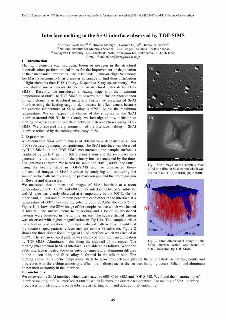
The 3rd Symposium on SIP Innovative measurement and analysis for structural materials (SIP-IMASM 2017) and TIA-Fraunhofer workshop
49
Interface melting in the Si/Al interface observed by TOF-SIMS
Norimichi Watanabe1), 2), Hiroaki Mamiya1), Daisuke Fujita1), Hideaki Kitazawa1) 1) National Institute for Materials Science, 1-2-1 Sengen, Tsukuba 305-0047 Japan
2) Kanagawa University, 3-27-1 Rokkakubashi, Kanagawa-Ku, Yokohama 221-8686 Japan E-mail: [email protected]
1. Introduction The light elements e.g. hydrogen, boron or nitrogen in the structural materials often perform crucial roles for the improvement or degradation of their mechanical properties. The TOF-SIMS (Time-of-flight Secondary Ion Mass Spectrometry) has a greater advantage to find their distribution of light elements than EDX (Energy Dispersive X-ray spectrometry). We have studied microelements distribution in structural materials by TOF-SIMS. Recently, we introduced a heating stage with the maximum temperature of 600°C to TOF-SIMS to observe the diffusion phenomenon of light elements in structural materials. Firstly, we investigated Si/Al interface using the heating stage to demonstrate its effectiveness because the eutectic temperature of Si-Al alloy is 575°C below the maximum temperature. We can expect the change of the structure in the Si/Al interface around 600 °C. In this study, we investigated how diffusion or melting progresses in the interface between different phases using TOF-SIMS. We discovered the phenomenon of the interface melting in Si/Al interface reflected by the etching anisotropy of Si. 2. Experiment Aluminum thin films with thickness of 200 nm were deposited on silicon (100) substrate by magnetron sputtering. The Si/Al interface was observed by TOF-SIMS. In the TOF-SIMS measurement, the sample surface is irradiated by 30 keV gallium (Ga+) primary ions and the secondary ions generated by the irradiation of the primary ions are analyzed by the time-of-flight mass analyzer. We heated the sample to 200°C, 400°C and 600°C using the heating stage in TOF-SIMS and we constructed three-dimensional images of Si/Al interface by analysing and sputtering the sample surface alternately using the primary ion gun and the argon gas gun. 3. Results and discussion We measured three-dimensional images of Si/Al interface at a room temperature, 200°C, 400°C and 600°C. The interface between Si substrate and Al layer was clearly observed at a temperature below 400°C. On the other hand, silicon and aluminum penetrate each other in the interface at a temperature of 600°C because the eutectic point of Al-Si alloy is 575 °C. Figure 1(a) shows the SEM image of the sample surface which was heated at 600 °C. The surface seems to be boiling and a lot of square-shaped patterns were observed in the sample surface. The square-shaped pattern was observed with higher magnification in Fig.1(b). The sample surface has a hollow configuration in the square-shaped pattern. It is thought that the square-shaped pattern reflects etch pit on the Si substrate. Figure 2 shows the three-dimensional image of Si/Al interface which was heated at 600°C. The square-shaped pattern was observed with high magnification by TOF-SIMS. Aluminum melts along the sidewall of the recess. The melting phenomenon in Si/Al interface is considered as follows. When the Si/Al interface is heated above its eutectic temperature, aluminum diffuses to the silicon side, and Si-Al alloy is formed in the silicon side. The melting above the eutectic temperature starts to grow from etching pits on the Si substrate as starting points and progresses with the etching anisotropy. When the melting reaches the surface, bumping occurs. Silicon and aluminum do not melt uniformly in the interface. 4. Conclusions We observed the Si/Al interface which was heated to 600 °C by SEM and TOF-SIMS. We found the phenomenon of interface melting in Si/Al interface at 600 °C which is above the eutectic temperature. The melting of Si/Al interface progresses with etching pits on Si substrate as starting point and does not melt uniformly.
Fig. 1 SEM images of the sample surface of Al thin film on Si substrate which was heated to 600℃ (a) ×1000, (b) ×7000.
(a)))
(b)
Fig. 2 Three-dimensional image of the Si/Al interface which was heated to 600℃ measured by TOF-SIMS.
Si+
Al+
30µm 30 µm

The 3rd Symposium on SIP Innovative measurement and analysis for structural materials (SIP-IMASM 2017) and TIA-Fraunhofer workshop
50
Informatics-aided Confocal Raman Microscopy for 3D Characterization of Stress in Silicon
Hongxin Wang 1), Han Zhang 1), Bo Da 1), Motoki Shiga 2), 3), Hideaki Kitazawa 1), Daisuke Fujita 1) 1) Research Center for Advanced Measurement and Characterization, National Institute for Materials Science, Sengen 1-2-1, Tsukuba,
Ibaraki, 3050047, Japan, [email protected] 2) Department of Electrical, Electronic and Computer Engineering, Gifu University, Yanagido 1-1, Gifu, Gifu, 5011193, Japan,
3) Precursory Research for Embryonic Science and Technology, Japan Science and Technology Agency, 4-1-8, Honcho, Kawaguchi, Saitama 332-0012, Japan
Confocal Raman microscopy (CRM) is a combination of two ingenious inventions of the past century: Raman spectroscopy and confocal microscopy. The concept utilizes a pin-hole aperture confocal with the specimen plane of interest to allow Raman scattering collection only from the excitation laser focal spot, thereby realizing physical chemistry analysis in a three-dimensional space [1]. Rigorously, only materials transparent to excitation laser follows this ideal picture of laser-specimen interaction. For an opaque material, signal attenuation may be caused by photon absorption besides the confocal exclusivity intended by the pin-hole aperture. This effect leads to inseparable signals generated at close specimen depths. The signal collected when the laser was focused at a single position would then contain spectral information from multiple positions along the specimen depth direction [2]. This effect compromises spatial selectivity and becomes especially noticeable in stress characterization, where Raman frequency shift caused by local stress in neighboring specimen regions usually differs by as little as a fraction of wavenumber. It is for this reason that depth-resolved 3D characterization of material stress by CRM is now limited only to specimen that is transparent to excitation laser in use [3]. To find a solution to this problem is urgent. As a typical example, Si is industrially important as the base material for microelectronics, MEMS/NEMS devices, solar cells and secondary batteries. Residue stresses in Si, intentionally created or unavoidably produced during device fabrication, play essential roles in device performance in applications. Si has long been used as a textbook example for 2D Raman stress analysis because of its well-understood Raman responsive vibration modes. However, till now, 3D stress analysis for Si using CRM stays unavailable because excitation laser wavelength opaque to Si has to be used in order to ensure adequate Raman scattering intensity. In recent years, informatics-aided Raman spectroscopy, which applied sophisticated mathematical methods on large number of acquired data, have made significant successes in revealing critical biochemical information for living systems under diverse physiological and pathological conditions. Though this type of informatic approach was developed mainly for organic/biological specimens, the 3D stress distribution in an inorganic material coincides with the targeted problem: a multivariate system with critical signals bearing only minor spectral changes. In this work, by calculating both laser attenuation from adsorption and confocal aperture exclusivity to reduce complexity, we applied an informatic-aided CRM approach to decompose true local stress values from the superposition of total Raman signals in three dimensions. The method assumes the mixture effect among laser signals from different 3D layers, which can be given by theoretical calculation, and then decomposes observed mixture signals into original ones to detect peak positions of Raman signals, to avoid specifically pseudo-peak generated from different layers (as shown in Figure 1). Its effectiveness was demonstrated by both synthetic dataset and real datasets in a silicon wafer pre-stressed by indentation. The local stress resolved from specimen planes separated with sub-micrometer distance was found to develop at different velocity in response to thermal annealing. Oxygen concentration gradient was accounted for such depth-dependent stress dynamic variation through impeding dislocation slip. Such mechanism was also confirmed quantitatively by 3D elemental analysis using Time-of-flight-secondary-ion-mass-spectroscopy (TOF-SIMS).
References [1] Dieing, T.; Hollricher, O.; Toporski, J. Confocal Raman Microscopy, Springer, (2010). [2] Bridges, T. E.; Houlne, M. P.; Harris, J. M. Spatially Resolved Analysis of Small Particles by Confocal Raman Microscopy:
Depth Profiling and Optical Trapping. Anal. Chem. 76, 576-584, (2004). [3] Wermelinger, T.; Borgia, C.; Solenthaler, C.; Spolenak, R. 3-D Ramanspectroscopy Measurements of the Symmetry of
Residual Stress Fields in Plastically Deformed Sapphire Crystals. Acta Mater. 55, 4657-4665, (2007).
Fig. 1. Left: CRM laser-specimen interaction in an opaque material which contains internal stresses of different types. Right: the collected total scattering signal is composed of local scattering signals modulated by attenuations from photon absorption and confocal aperture exclusivity.

The 3rd Symposium on SIP Innovative measurement and analysis for structural materials (SIP-IMASM 2017) and TIA-Fraunhofer workshop
51
Study of the nanoparticles influence on the mechanical properties of Ni-fee N-containing ODS alloy by alloy contrast variation analysis
A. Mori1) 2), H. Mamiya1), J. Ilavsky3), E. Giblert4), M. Ohnuma5), H. Kitazawa1), M. Lewandowska2); 1) Research Center for Advanced Measurement and Characterization, National Institute for Materials Science (NIMS)
2) Faculty of Materials Science and Engineering, Warsaw University of Technology (WUT) 3) X-Ray Science Division, Advanced Photon Source, Argonne National Laboratory, 9700 S. Cass Avenue, bldg 433A002, Argonne,
IL 60439 (USA) 4) Australian Nuclear Science and Technology Organization (ANSTO) (Australia)
5) Faculty of Engineering, Hokkaido University, Kita 13, Nishi 8, Kita-ku, Sapporo, Hokkaido 060-8628 (Japan)
The nickel-free nitrogen-containing austenitic oxide dispersion strengthened (ODS) steels become interesting materials for the application in future fusion and fission reactors. One of the most important issues in the ODS materials is to understand the influence of nanoparticles size on the strengthening which is described by the Orowan’s formula [1]. Another important matter is the chemical composition of the nanoparticles, which control their thermal stability and consequently effect the material’s properties. Therefore, we have applied an alloy contrast variation (ACV) analysis[1] using combining of conventional ultra-small angle X-ray and neutron scattering (USAXS and SANS) methods to solve these problems. The ACV method is based on the difference of scattering length of each element, which is described as a ratio of intensity between SANS and USAXS. The analysis allows to obtain quantitively information of the size and chemical composition of the nanoparticles. The SANS measurement was performed using the QUOKKA[2] device in Australian Nuclear Science and Technology Organization (ANSTO). The dimension of a typical sample was 1x1x0.8 cm. Each sample was measured in three positions of the detector. The q-range covered is from 0.003 to 7.4 Å-1. For the USAXS measurement was used the USAXS-device[3] in Argonne National Laboratory, with q-range from 0.0001 to 5.9 Å-1. For the ACV analysis was used Modeling II[4] in Irena software. The ACV analysis was combined with TEM and EDS observations. The mechanical properties were determined by Vickers micro hardness test.
Fig. 1 ACV analysis showing two population of Y2O3 and MnO nanoparticles
To study influence of the nanoparticles on the mechanical properties, the material was annealed in temperature range from 700 °C to 1000 °C for 1 h. The analysis shows MnO nanoparticles with a diameter of about 80 nm and two population of Y2O3 nanoparticles with a size of about 12-6 nm. The micro hardness of the material changes with annealing temperature. The peak of hardness was obtained in 800 °C. In the same temperature was observed the highest number of ultra-fine nanoparticles with size below 10 nm. the fine nanoparticles. The presence of MnO and Y2O3 was confirmed by TEM combined with EDS. There were also determined other kinds of nanoparticles.
References [1] M. Ohnuma et al., “A new method for the quantitative analysis of the scale and composition of nanosized oxide in 9Cr-ODS
steel,” Acta Mater., vol. 57, no. 18, pp. 5571–5581, 2009. [2] E. P. Gilbert, J. C. Schulz, and T. J. Noakes, “‘Quokka’-the small-angle neutron scattering instrument at OPAL,” Phys. B
Condens. Matter, vol. 385–386, pp. 1180–1182, 2006. [3] J. Ilavsky, P. R. Jemian, A. J. Allen, F. Zhang, L. E. Levine, and G. G. Long, “Ultra-small-angle X-ray scattering at the
Advanced Photon Source,” J. Appl. Crystallogr., vol. 42, no. 3, pp. 469–479, 2009. [4] J. Ilavsky and P. R. Jemian, “Irena: Tool suite for modeling and analysis of small-angle scattering,” J. Appl. Crystallogr.,
vol. 42, no. 2, pp. 347–353, 2009.
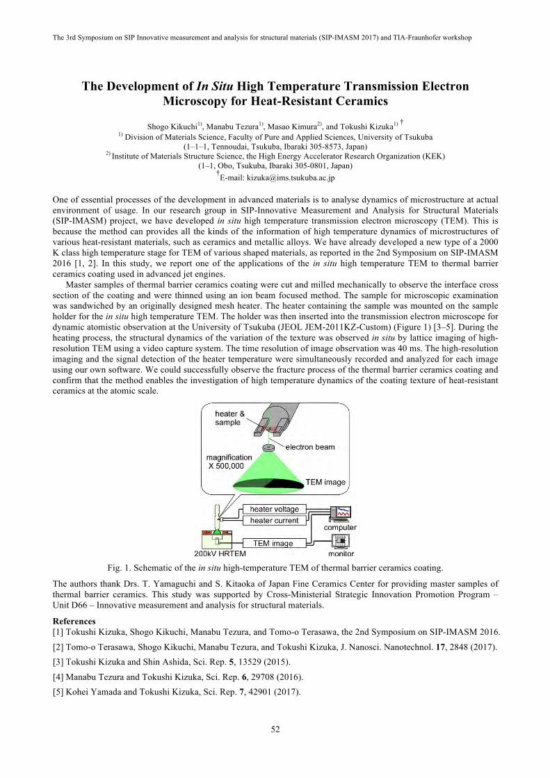
The 3rd Symposium on SIP Innovative measurement and analysis for structural materials (SIP-IMASM 2017) and TIA-Fraunhofer workshop
52
The Development of In Situ High Temperature Transmission Electron Microscopy for Heat-Resistant Ceramics
Shogo Kikuchi1), Manabu Tezura1), Masao Kimura2), and Tokushi Kizuka1) † 1) Division of Materials Science, Faculty of Pure and Applied Sciences, University of Tsukuba
(1–1–1, Tennoudai, Tsukuba, Ibaraki 305-8573, Japan) 2) Institute of Materials Structure Science, the High Energy Accelerator Research Organization (KEK)
(1–1, Obo, Tsukuba, Ibaraki 305-0801, Japan) †E-mail: [email protected]
One of essential processes of the development in advanced materials is to analyse dynamics of microstructure at actual environment of usage. In our research group in SIP-Innovative Measurement and Analysis for Structural Materials (SIP-IMASM) project, we have developed in situ high temperature transmission electron microscopy (TEM). This is because the method can provides all the kinds of the information of high temperature dynamics of microstructures of various heat-resistant materials, such as ceramics and metallic alloys. We have already developed a new type of a 2000 K class high temperature stage for TEM of various shaped materials, as reported in the 2nd Symposium on SIP-IMASM 2016 [1, 2]. In this study, we report one of the applications of the in situ high temperature TEM to thermal barrier ceramics coating used in advanced jet engines.
Master samples of thermal barrier ceramics coating were cut and milled mechanically to observe the interface cross section of the coating and were thinned using an ion beam focused method. The sample for microscopic examination was sandwiched by an originally designed mesh heater. The heater containing the sample was mounted on the sample holder for the in situ high temperature TEM. The holder was then inserted into the transmission electron microscope for dynamic atomistic observation at the University of Tsukuba (JEOL JEM-2011KZ-Custom) (Figure 1) [3–5]. During the heating process, the structural dynamics of the variation of the texture was observed in situ by lattice imaging of high-resolution TEM using a video capture system. The time resolution of image observation was 40 ms. The high-resolution imaging and the signal detection of the heater temperature were simultaneously recorded and analyzed for each image using our own software. We could successfully observe the fracture process of the thermal barrier ceramics coating and confirm that the method enables the investigation of high temperature dynamics of the coating texture of heat-resistant ceramics at the atomic scale.
Fig. 1. Schematic of the in situ high-temperature TEM of thermal barrier ceramics coating.
The authors thank Drs. T. Yamaguchi and S. Kitaoka of Japan Fine Ceramics Center for providing master samples of thermal barrier ceramics. This study was supported by Cross-Ministerial Strategic Innovation Promotion Program – Unit D66 – Innovative measurement and analysis for structural materials.
References [1] Tokushi Kizuka, Shogo Kikuchi, Manabu Tezura, and Tomo-o Terasawa, the 2nd Symposium on SIP-IMASM 2016.
[2] Tomo-o Terasawa, Shogo Kikuchi, Manabu Tezura, and Tokushi Kizuka, J. Nanosci. Nanotechnol. 17, 2848 (2017). [3] Tokushi Kizuka and Shin Ashida, Sci. Rep. 5, 13529 (2015).
[4] Manabu Tezura and Tokushi Kizuka, Sci. Rep. 6, 29708 (2016). [5] Kohei Yamada and Tokushi Kizuka, Sci. Rep. 7, 42901 (2017).

The 3rd Symposium on SIP Innovative measurement and analysis for structural materials (SIP-IMASM 2017) and TIA-Fraunhofer workshop
53
Two-dimensional Mapping of Hydrogen in Thick Films with Microbeam Transmission ERDA Method
A. Yamazaki1), H. Naramoto2), K. Sasa1,2), S. Ishii2), M. Kurosawa3), S. Tomita1), M. Sataka2), H. Kudo2), M. Ohkubo4), A. Uedono1,2) 1) Faculty of Pure and Applied Sciences, University of Tsukuba,
1-1-1 Tennodai, Tsukuba, Ibaraki 305-8571, Japan phone: +81-29-853-2498, fax: +81-29-853-2565,
E-mail: [email protected] 2) Research Facility Center for Science and Technology, University of Tsukuba,
1-1-1 Tennodai, Tsukuba, Ibaraki 305-8577, Japan 3) Faculty of Life and Environmental Sciences, University of Tsukuba,
1-1-1 Tennodai, Tsukuba, Ibaraki 305-8572, Japan 4) National Institute of Advanced Industrial Science and Technology (AIST),
1-1-1 Umezono, Tsukuba, Ibaraki 305-8568, Japan
Light trace elements in structural materials often affect their characteristics and many researchers have a great interest in behaviour of trace elements in materials. Particle induced X-ray emission (PIXE) method is a powerful tool for analysis of trace elements. In 2016, a new ion microbeam focusing and scanning system has been completed in our facility. The main purpose of our microbeam system is to investigate the distribution of the light trace elements in structural materials by the PIXE method, and using a thin window silicon drift detector (SDD) we are just going to obtain two-dimensional maps of light elements in sample materials [1].
Among the light elements hydrogen plays an important role for determining the mechanical properties of materials, for example, hydrogen uptake often causes embrittlement and blistering of the materials. However, PIXE method is not applicable for analyzing the distribution of hydrogen in material because of no characteristic X-ray emission and other detection methods for hydrogen are indispensable.
Elastic recoil detection analysis (ERDA) method is one of useful methods for detecting hydrogen in material. In addition, ERDA in transmission geometry (transmission ERDA) can provide depth profile of hydrogen in thick films [2]. Combining our ion microbeam scanning system with the transmission ERDA we are trying some examinations for simultaneous mapping of light elements including hydrogen in materials.
Figure 1 shows an example of the hydrogen and copper distributions which was obtained by scanning irradiation of helium on a three-layered test sample which consists of copper grid, thin Mylar and thick aluminum. Helium ion can recoil proton in Mylar film with sufficient energy to penetrate through aluminum but helium through the copper grid does not have sufficient energy and then recoiled proton cannot penetrate through aluminum and as a result cannot be detected. Therefore the maps of hydrogen and copper are complementary in their intensities to each other as shown in Fig. 1. Some results of hydrogen detection will be presented at the conference.
Fig. 1. Elemental distributions of hydrogen taken by transmission ERDA method (left) and copper by PIXE
method (right).
References [1] A. Yamazaki, K. Sasa, S. Ishii, M. Kurosawa, S. Tomita, S. Shiki, G. Fujii, M. Ukibe, M. Ohkubo, A. Uedono, E. Kita,
“Development of a microbeam PIXE system for additive light elements in structural materials”, Nucl. Instrum. methods B 404, 92-95 (2017)
[2] J. Tirira, P. Trocellier, J.P. Frontier, Analytical capabilities of ERDA in transmission geometry, Nucl. Instrum. Methods B 45, 147-150 (1990)

The 3rd Symposium on SIP Innovative measurement and analysis for structural materials (SIP-IMASM 2017) and TIA-Fraunhofer workshop
54
Development of In Situ High-Temperature Transmission Electron Microscopy Using Micrometer Regional Pinpoint Heating
Hideki Kobayashi1), Manabu Tezura1) and Tokushi Kizuka1) † 1) Division of Materials Science, Faculty of Pure and Applied Sciences, Univ. of Tsukuba
(1-1-1, Tennoudai, Tsukuba, Ibaraki 305-8573, Japan) †E-mail: [email protected]
Advanced structural materials have been used in various kinds of ultimate environments. In particular, heat-resistant materials used in the elements of jet engines and aircrafts are subjected to high temperatures up to 1700 K. In addition, high strain and stress caused by thermal expansion at such high temperatures lead to fatal damages of the advanced heat-resistant materials. Thus, to develop advanced heat-resistant structural materials, we need an effective method to observe directly the microstructural dynamics in replicated conditions of environments of actual usage. In situ transmission electron microscopy (TEM) of mechanical deformation of materials at high temperatures achieves full potential of realization of such investigation and serves indubitably one of the objectives of the project relating to this symposium. However, some problems in apparatuses using in previously-developed in situ TEM have stunted the application; the maximum heating temperature had been at highest ~1000 K and the deformation manner had been restricted to uniaxial tensile ones with rough displacement steps of micrometer scales. For the improvement of heating temperature, we already developed a new type of a 2000 K class high temperature stage for TEM, as reported in the 1st and 2nd Symposia (SIP-IMASM 2015 and 2016) [1–3].
During heating of TEM samples at high temperature exceeding 1000 K, there are some problems that hold back progress of high temperature in situ TEM. One of them is the increase in the amount of outgas from samples, heaters, and the constituent parts of electron microscopes around the heaters, such as pole-pieces, electron lenses, and apertures. A way to improve this is to decrease the amount of thermal emission, i.e., to decrease heating regions. In this study, we report the development of a micrometer-scale regional pinpoint heating technique using picometer-precision heater-position control for high temperature in situ TEM (Figure 1) [4–6].
Fig. 1. Schematic of pinpoint heating of sample for high temperature in situ TEM.
This study was supported by Cross-Ministerial Strategic Innovation Promotion Program – Unit D66 – Innovative measurement and analysis for structural materials.
References [1] Tomo-o Terasawa and Tokushi Kizuka, the 1st Symposium on SIP-IMASM 2015.
[2] Tokushi Kizuka, Shogo Kikuchi, Manabu Tezura, and Tomo-o Terasawa, the 2nd Symposium on SIP-IMASM 2016. [3] Tomo-o Terasawa, Shogo Kikuchi, Manabu Tezura, and Tokushi Kizuka, J. Nanosci. Nanotechnol. 17, 2848 (2017).
[4] Tokushi Kizuka and Shin Ashida, Sci. Rep. 5, 13529 (2015).
[5] Manabu Tezura and Tokushi Kizuka, Sci. Rep. 6, 29708 (2016). [6] Kohei Yamada and Tokushi Kizuka, Sci. Rep. 7, 42901 (2017).
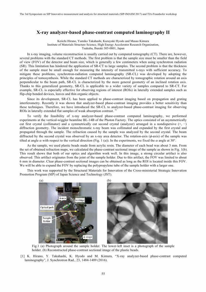
The 3rd Symposium on SIP Innovative measurement and analysis for structural materials (SIP-IMASM 2017) and TIA-Fraunhofer workshop
55
X-ray analyzer-based phase-contrast computed laminography II
Keiichi Hirano, Yumiko Takahashi, Kazuyuki Hyodo and Masao Kimura Institute of Materials Structure Science, High Energy Accelerator Research Organization,
Tsukuba, Ibaraki 305-0801, Japan
In x-ray imaging, volume reconstruction is usually carried out by computed tomography (CT). There are, however, several problems with the standard CT methods. The first problem is that the sample size must be smaller than the field of view (FOV) of the detector and beam size, which is generally a few centimeters when using synchrotron radiation (SR). This limitation has hindered the application of SR-CT to large samples. The second problem is that the thickness of the sample must be small enough for measuring the intensity of transmitted x-rays with sufficient accuracy. To mitigate these problems, synchrotron-radiation computed laminography (SR-CL) was developed by adopting the principles of tomosynthesis. While the standard CT methods are characterized by tomographic rotation around an axis perpendicular to the beam path, SR-CL is characterized by the more general geometry of an inclined rotation axis. Thanks to this generalized geometry, SR-CL is applicable to a wider variety of samples compared to SR-CT. For example, SR-CL is especially effective for observing regions of interest (ROIs) in laterally extended samples such as flip-chip bonded devices, leaves and thin organic objects.
Since its development, SR-CL has been applied to phase-contrast imaging based on propagation and grating interferometry. Recently it was shown that analyzer-based phase-contrast imaging provides a better sensitivity than these techniques. Therefore, we have introduced the SR-CL to analyzer-based phase-contrast imaging for observing ROIs in laterally extended flat samples of weak absorption contrast. 1)
To verify the feasibility of x-ray analyzer-based phase-contrast computed laminography, we performed experiments at the vertical-wiggler beamline BL-14B of the Photon Factory. The optics consisted of an asymmetrically cut first crystal (collimator) and a symmetrically cut second crystal (analyzer) arranged in a nondispersive (+, −) diffraction geometry. The incident monochromatic x-ray beam was collimated and expanded by the first crystal and propagated through the sample. The refraction caused by the sample was analyzed by the second crystal. The beam diffracted by the second crystal was observed by an x-ray area detector. The rotation-axis (f-axis) of the sample was tilted at angle a with respect to the vertical direction (Fig. 1 (a)). In the experiments, we fixed the a angle at 30°.
As the sample, we used plastic beads made from acrylic resin. The diameter of each bead was about 3 mm. From the set of obtained refraction maps, we calculated the phase-contrast sectional image of the sample as shown in Fig. 1(b). This result shows that both of our optics and algorithm work well. In this image, a strong circular artifact is also observed. This artifact originates from the joint of the sample holder. Due to this artifact, the FOV was limited to about 6 mm in diameter. Clear phase-contrast sectional images can be obtained as long as the ROI is located inside this FOV. We will be able to expand the FOV by replacing the polypropylene tube of the sample holder with a larger one.
This work was supported by the Structural Materials for Innovation of the Cross-ministerial Strategic Innovation Promotion Program (SIP) of Japan Science and Technology (JST).
(a) (b)
Fig.1 (a) Photograph around the sample holder. The lower-left inset is a photograph of the sample holder. (b) Reconstructed phase-contrast sectional image of the plastic beads.
[1] K. Hirano, Y. Takahashi, K. Hyodo and M. Kimura, “X-ray analyzer-based phase-contrast computed laminography”, J. Synchrotron Rad., 23, 1484-1489 (2016).

The 3rd Symposium on SIP Innovative measurement and analysis for structural materials (SIP-IMASM 2017) and TIA-Fraunhofer workshop
56
TIA-Fraunhofer workshop

The 3rd Symposium on SIP Innovative measurement and analysis for structural materials (SIP-IMASM 2017) and TIA-Fraunhofer workshop
57
The Fraunhofer Composite Lightweight Alliance
Henning Heuer
Fraunhofer is Europe’s largest application-oriented research organization. Our research efforts are geared entirely to people’s needs: health, security, communication, mobility, energy and the environment. As a result, the work undertaken by our researchers and developers has a significant impact on people’s lives. Over 25 000 mostly science orientated staff members are creative by shaping technology and design products. Fraunhofer consist of 70 institutes distributed over Germany each dedicated to a specific research topic. In order to accelerate actual research topics, the institutes are collaborating within thematic orientated Alliances. The 18 institutes that make up the Fraunhofer Composite Lightweight Design Alliance bring together expertise in a number of field’s related to composite technology as: materials and material composites, joining techniques and manufacturing processes for lightweight construction, numerical and experimental simulation, and evaluation of components and systems. In detail the Key fields of research are:
• New materials and material composites • Manufacturing and joining technologies relevant to lightweight construction • Functional integration • Design and configuration • Non-destructive and destructive test methods
The keynote presentation will shorty introduce to Fraunhofer Gesellschaft and to collaboration models. Followed by a general introduction to the main scope of composite based lightweight research.

The 3rd Symposium on SIP Innovative measurement and analysis for structural materials (SIP-IMASM 2017) and TIA-Fraunhofer workshop
58
Nondestructive Characterization and Evaluation of Adhesive Bondings – R&D
Prof. Dr.- Ing. Bernd Valeske, Vice Director Fraunhofer IZFP / Head of Department NDT and NDE of Components and Assemblies/
Fraunhofer Innovation Center for Auomotive Quality Saar AQS (Saarbruecken, Germany)
Adhesive Bonding is a critical process that is hard to be controlled and in general it is considered as a technology that is very sensitive to many kinds of influences. So, in order to benefit from all the design and the functional properties of adhesive bonding, and in order to produce high-quality and safe adhesive bonds, especially for structural bonding applications an extensive non-destructive quality control concept is required. In this presentation it is demonstrated how advanced non-destructive testing can be embedded into customized quality control for applications of adhesive bonding in the automotive industry. Different sensor principles are shown that contribute to assure a robust bonding procedure taking into account pre-process, in-process and post-process non-destructive inspection. Prototype applications for adhesive bonding in automotive industry are shown that can be used for assembly or structural bondings (body-in-white). Besides classical defect detection by NDT (detection of delaminations, cavities, debondings) some new technologies are shown that focus further more on the characterization of the polymer microstructure and on the resulting molecular dynamics and material properties. These so called extended ndt methods (E-NDT) allow for characterization of the most relevant adhesive properties and have the potential to non-destructively derive parameters to evaluate the bond performance. NDT methods and applications covered in this presentation are: Ultrasound, Phased Array Ultrasound imaging, airborne ultrasound, thermography, shearography, X-ray computed tomography and advanced image processing / pattern recognition based on these sensor principles. E-NDT approaches cover FT-IR spectroscopy, NMR relaxation measurements and LASER-shock testing.

The 3rd Symposium on SIP Innovative measurement and analysis for structural materials (SIP-IMASM 2017) and TIA-Fraunhofer workshop
59
Online monitoring and classification of carbon fiber and textile production defects using scalable line scan optics and computer vision
Andreas Margraf1), Steffen Geinitz2), André Wedel3) 1) 2) 3) Fraunhofer IGCV, Am Technologiezentrum 2, 86159 Augsburg, +49 821 90678424, [email protected]
With a growing market of CFRP, online quality inspection becomes more important, especially for environments with high safety standards. An increasing need for efficiency and automation drives the demand for individual industrial solutions. For that reason, Fraunhofer IGCV made efforts in developing monitoring systems for defect detection on CFRP structures. Filament misalignments, fractures as well as fuzz balls within the carbon fiber production have a substantial impact on the roving quality and therefore on the final product performance [1]. Some effort has been made in monitoring the surface of textiles [2], but cannot be applied in the same manner on CFRP. Due to the lack of alternatives, visual inspection is still a common approach for quality inspection. However, the human eye generally does not meet industrial standards in terms of reliability, repeatability and speed. In order to address this issue, Fraunhofer IGCV developed an optical measurement system for online monitoring in the production process based on self-learning concepts for CFRP and beyond. The applications comprise the detection carbon fiber (CF) defects in the range of 10 microns and detecting gaps in nitted carbon fibers (NCF) [2, 3] as can be seen in Figure 1. Deviations from ideal patterns can be located likewise. Apart from that, binder distribution is another feature concerning the production of composites. In this context, Fraunhofer IGCV designed a software able to evaluate binder distribution and its homogeneity on NCF. Since every monitoring task requires an adapted image processing pipeline, Fraunhofer IGCV also implemented a solution reducing the time needed for development. With the use of an evolutionary computing approach a first step towards a self-optimizing defect detection pipeline for flaw detection within carbon fiber production is presented. A further, but also important topic is the classification of defects. In the context of its studies, Fraunhofer IGCV developed a concept for carbon fiber defect classification that is combined with the aforementioned monitoring system in order to form a semi-automated monitoring system. With the data at hand, the software includes a concept for data processing and storage for further analysis.
Fig. 1. Detection of nitting gaps (left), loose filaments (center) and fuzzballs (left) on carbon fiber rovings
References [1] Bunsell, A. R.: Fibre reinforcements for composite materials. Composite materials series, Bd. 2. Amsterdam, New
York: Elsevier 1988 [2] D.-M. Tsai, C.-Y. Hsieh: Automated surface inspection for directional textures. (1999). [3] Geinitz S., Wedel A., Margraf A.: Online detection and categorization of defects along a carbon fibre scan vision
system. WCNDT, Munich, 2016 [4] Geinitz S., Wedel A., Margraf A., Drechsler K.: Detection of Filament Misalignment in Carbon Fiber Production
Using a Stereovision Line Scan Camera System. ECCM, Munich, 2016

The 3rd Symposium on SIP Innovative measurement and analysis for structural materials (SIP-IMASM 2017) and TIA-Fraunhofer workshop
60
Correlation between micro- and macroscopic characterization of recycled carbon fibre materials
Frank Manis1), Ananda Schindler2) Michael Sauer3) and Jakob Wölling4) 1) 2) 3) 4) Fraunhofer IGCV, Am Technologiezentrum 2, 86159 Augsburg, +49 821 90678-229, [email protected]
Nowadays various research and development projects are focused on recycled carbon fibres (rCF) aiming at the substitution of virgin ones within industrial applications. Due to a thermal separation process it is possible to get rid of char and achieve clean carbon fibres, but the mechanical properties of the single filaments might suffer in oxidative atmosphere. To comprehend the impact of this recycling process it’s not only important to understand the influence on the single filament level but also on a macroscopic level. It’s most widely unknown how a degradation of single filament strength is correlated with tensile strength of the carbon fibre reinforces plastic (CFRP) or how a changed fibre matrix adhesion will influence the composite properties. Unfortunately, an additional fibre shortage and adapted processing routes are creating even more difficulty within correlation of rCF properties as compared to virgin CFRP in correct manner [1 -5].
For this reason, in this study carbon fibre reinforces plastics are pyrolysed and oxidised in near-industrial conditions without destroying the architecture of the CFRP. Subsequently a (re)infiltration step is used to produce CFRP out of rCF. Tensile tests on the single filament level as well as on the composite level are carried out in order to highlight the upcoming correlations and effects on both material levels. Therefor different characterization technologies are presented, correlated and evaluated.
Fig. 1. Different material properties and interactions at all material levels, as well as associated influences of
specific recycling processes within the new process chain.
References [1] G. Oliveux, L. O. Dandy, G. A. Leeke, “Current status of recycling of fibre reinforced polymers: Review of technologies, reuse
and resulting properties”, Progress in Material Science 72 61-99 (2015). [2] S. Pimenta, “Toughness and strength of recycled composites and their virgin precursors”, doctoral thesis (2013). [3] S. J. Pickering, “Recycling technologies for thermoset composite materials—current status”, Composites: Part A 37, 1206-
1215 (2006). [4] J. Wölling, M. Schmieg, F. Manis, K. Drechsler, “Nonwovens from recycled carbon fibres – comparison of processing
technologies”, Procedia CIRP, 271-276 (2017). [5] F. Manis, J. Wölling, K. Drechsler, “Damage behaviour of fibre reinforced materials induced by high temperature oxidation for
optimisation of thermal recycling routes”, 20th Symposium on Composites Part 2, 1088-1095 (2015).

The 3rd Symposium on SIP Innovative measurement and analysis for structural materials (SIP-IMASM 2017) and TIA-Fraunhofer workshop
61
Adhesion and Interfacial Phenomena Research Laboratory (AIRL)
Chiaki Sato AIRL, National Institute of Advanced Industrial Science and Technology
Adhesive bonding has been utilized for manufacturing a wide range of industrial products such as electronic appliances, cars, and aircrafts. For further innovations in these products, studies focusing on "adhesion" in addition to the interfacial phenomena are necessary. In order to carry out such a focused study, we established the Adhesion and Interfacial Phenomena Research Laboratory in AIST in December 2015. The objective of this research laboratory is to promote research and development intended for a wide range of products ranging from basic ones to those requiring next-generation adhesives, by collaborating with the industry, academia, and government.
The main research themes of this laboratory include bonding interface evaluation, development of new adhesive materials, strength and reliability evaluation of adhesive joints, and development of surface treatment and testing methods, as shown below. The most important endeavor of this laboratory is to promote industry-academia-government collaboration through various projects. If you have a technical problem, please contact us without hesitation.

The 3rd Symposium on SIP Innovative measurement and analysis for structural materials (SIP-IMASM 2017) and TIA-Fraunhofer workshop
62
Numerical simulation of mid-IR Ultrasound testing in CFRP
Kanae Oguchi1), Manabu Enoki1), Hisashi Yamawaki2) , Masahiro Kusano2) , Makoto Watanabe2) 1) Department of Materials Engineering, The University of Tokyo, 7-3-1 Hongo, Bunkyo-ku, Tokyo 113-8656 Japan
2) Integrated Smart Materials Gr., National Institute for Materials Science, 1-2-1, Sengen, Tsukuba-shi, Ibaraki 305-0047 Japan
E-mail: [email protected]
Introduction: CFRP are used as structure materials of aircraft and automobile for their light weight, high strength and rigidity. During the operation, under the dynamic load in a harsh environmental condition, periodical NDT is necessity for CFRP members to avoid the fatal defect which lead to severe accidents. Thus effective on-line quality inspection method is demanded. Dubois presented that the irradiation of the light with the wavelength in the vicinity of 3.2µm can excite the ultrasound wave effectively in CFRP for the appropriate value of optical depth [1]. We are developing an optical parametric oscillator to generate mid-IR light, and trying to build an accurate and efficiency LUT system for CFRP using a mid-IR light [2][3]. To develop the practical system, we conducted the evaluation of the various factors, and found that the thickness of the sample surface epoxy effect a lot to the characteristics of the generated ultrasound. In this study, laser ultrasound propagation simulation in a CFRP-laminate with surface epoxy coating is developed, and performed the simulation to analyse the effects of the epoxy layer on the amplitude of generated ultrasound.
Results: Figure 1 show the experimental result of the C-scan image of the CFRP sample with the artificial defects without epoxy layer and with 40µm-thick epoxy layer. It is clearly identified as shown in Fig.1(a), even for the case without the epoxy layer. But when comparing with the epoxy coated case, the significant SNR improvement is recognized Fig.1(b). Figure 2 show the simulated ultrasound displacement distribution in CFRP-laminate with and without epoxy layer at 0.2µs after the laser irradiation. In a figures, the longitudinal wave (L-wave) generated by mid-IR laser irradiation propagates toward the back-surface, and the displacement of the L-wave in a coated sample is obviously bigger than that in an uncoated sample.
Future aspect: In addition to the ultrasound testing for the defect of several mm, as shown in above, we aim at the detection of the closed crack (kissing-bond) . When the crack surfaces stay in very close contact with each other, the bond between the two surfaces of the crack is called a ‘kissing bond’. Since it is very difficult to detect the kissing-bond by conventional ultrasound testing, the non-linear ultrasound technique gathers attention. In this method, the large amplitude ultrasound that propagates over the closed crack generates the non-linear ultrasound containing the harmonic and sub-harmonic component at the interface. And utilising the amplitude of harmonic or sub-harmonic component for inspection, kissing-bond can be detected. To understand the generating mechanism of non-linear ultrasound, we developed the 2D simulation model with closed crack defect, and carried out ultrasound propagation simulation. As a result, we confirmed the saw-like shaped transmission wave containing the second and third harmonic component at the interfacial region.
References [1] M. Dubois, P. W. Lorraine, R. J. Filkins, T. E. Drake, K.R. Yawn K R and S-Y Chuang, Ultrasonics, 40, 809 (2002). [2] H. Hatano, M. Watanabe, K. Kitamura, M. Naito, H. Yamawaki and R. Slater, J. Opt. 17, 094011 (2015). [3] H. Hatano, R. Slater, S. Takekawa, M. Kusano, and M. Watanabe, Jpn. J. Appl. Phys. 56. 72701, 1(2017).
Fig.1 calculated ultrasound displacement distribution in CFRP-laminate without epoxy layer (a) and with 40µm-thick epoxy layer (b) at 0.2µs after the laser irradiation.
Fig. 2 experimental result of C-scan image of the CFRP sample with the artificial defects without epoxy layer (a) and with 40µm-thick epoxy layer (b).

The 3rd Symposium on SIP Innovative measurement and analysis for structural materials (SIP-IMASM 2017) and TIA-Fraunhofer workshop
63
Molecular Adhesion Behavior of Polymer-Metal Interfaces: A Molecular Dynamics Simulation Study
Toshiaki Miura1), Maki Funada2), Yukihiro Shimoi1), Hiroshi Morita1) 1) National Institute of Advanced Industrial Science and Technology (AIST), 1-1-1 Umezono, Tsukuba 305-8568, Japan
phone: +81-29-861-5376, fax: +81-29-861-5547, [email protected] 2) Innovative Structural Materials Association, 1-9-4, Yurakucho, Chiyoda-ku, Tokyo 100-0006, Japan
Adhesion between dissimilar materials has attracted much attention due to its potential contribution to the weight-reduction of vehicles and airplanes. The microscopic mechanisms of adhesion are complex and related to various phenomena with different scales like molecular interaction at interfaces, cross-linking and entanglement of polymers, phase separation of adhesives, and so on (See Fig.1). In this presentation, we will introduce our molecular dynamics (MD) simulation on adhesion behavior of polymer-metal interfaces. We mainly focus our attention on the influence of nano-scale structure at interface.
We prepare the system of metal–polymer–metal sandwich composites with nano-sized porous. To obtain tensile and shear mechanical properties, we pull the metals up and down or slide them to the left and right after thermal equilibrium. We adopt oligomers of the poly(ethylene oxide) as polymers and aluminum layers as metals. Actual all-atom MD simulations have been carried out by Gromacs. Figure 2 shows a MD snapshot for tensile process where the polymers are not cross-linked. As seen the figure, fracture takes place at the middle part of polymer layer. Thus, we obtained a force curve against the displacement similar to the system with flat surfaces. Meanwhile, for the shear process, the behavior depends on the interface structures: we obtain higher yield strength for the surface with the nano porous than the flat surface. We will also mention the effects of the cross-linking of the polymers on the adhesion behavior.
Fig. 1. Issues of adhesion mechanism and simulations. Fig. 2. MD snapshot for the tensile process.

The 3rd Symposium on SIP Innovative measurement and analysis for structural materials (SIP-IMASM 2017) and TIA-Fraunhofer workshop
64
Bus stops for free AIST shuttle and public bus services
The free AIST buses run every ~30 min. between Tsukuba express (TX) Tsukuba station and AIST campus. The symposium site is very close to the bus stop inside the campus. The public buses are more frequent, but the bus stop is outside the campus. The highway buses also take you to Tokyo station. See the locations of the bus stops.
Bus stop at TX Tsukuba station
Bus stops at AIST campus

The 3rd Symposium on SIP Innovative measurement and analysis for structural materials (SIP-IMASM 2017) and TIA-Fraunhofer workshop
65
Timetable of free AIST shuttle bus
Public buses are available every ~10 min. till 22:38 between TX Tsukuba station and AIST campus (Namiki 2 chome bus stop).

The 3rd Symposium on SIP Innovative measurement and analysis for structural materials (SIP-IMASM 2017) and TIA-Fraunhofer workshop
66
Lunch guide
There is a cafeteria in front of the symposium site. You have to get a pre-paid card at the entrance. 1. Touch the screen “カード発行.” 2. Insert paper money (1,000, 5,000, or 10,000 JPY). 3. Choose the amount you want to deposit. 500 JPY is additionally charged for the
card. Please take your meal, and pay it at a cashier using the card. You can have the charged money and the 500 JPY refunded, when you don’t use the card anymore. Please ask a Japanese staff, if you have questions.

The 3rd Symposium on SIP Innovative measurement and analysis for structural materials (SIP-IMASM 2017) and TIA-Fraunhofer workshop
67
Program & Abstract Booklet 3rd Symposium on Innovative Measurement and Analysis for Structural Materials (SIP-IMASM2017) and TIA-Fraunhofer workshop
Published on September 26, 2017 Editor
National Institute of Advanced Industrial Science and Technology (AIST) 1-1-1, Umezono, Tsukuba, Ibaraki, 305-8568, Japan Committee for the 3rd Symposium on Innovative Measurement and Analysis for Structural Materials TEL: 029-861-5685, URL: https://staff.aist.go.jp/m.ohkubo/SIP-IMASM e-mail: [email protected] Masataka Ohkubo (Chair, AIST), Lorenz Granrath(AIST), Paul Fons (AIST), Brian ORouke (AIST), Yoshihisa Harada (AIST), Hiroaki Mamiya (NIMS), Akira Uedono (University of Tsukuba), Masao Kimura (KEK), Makoto Watanabe (NIMS), Kimikazu Sasa (University of Tsukuba), and Yasuo Takeichi (KEK)
No part of this report should be reproduced or copied without permission from the editor and the authors. アブストラクト2017
第3回 革新的構造材料のための先端計測拠点 国際会議 TIA-Fraunhofer合同シンポジウム
2017年9月26日 発行
編 者 国立研究開発法人 産業技術総合研究所 〒305-8568 茨城県つくば市梅園1-1-1 「第3回 革新的構造材料のための先端計測拠点 国際会議」実行委員会 大久保 雅隆(AIST)、グランラート,ロレンツ(AIST)、フォンス, ポール(AIST)、オローク, ブライアン(AIST)、原田 祥久(AIST)、間宮 広明(NIMS)、上殿 明良(筑波大)、木村 正雄(KEK)、渡邊 誠 (NIMS)、笹 公和(筑波大)、武市泰男(KEK) TEL: 029-861-5685, URL: https://staff.aist.go.jp/m.ohkubo/SIP-IMASM e-mail: [email protected]
編者及び著者の許可なく本報告集の全部もしくは一部を転載あるいは複製することを禁じます。

AIST17-K00005