Embed Size (px)
Citation preview

21–1
SensorsTable of ContentsCurrent Sensors Overview . . . . . . . . . . . . 21–2Application Guide. . . . . . . . . . . . . . . . . . . . . . . . 21–3ACT Series Current Transducers . . . . . . . . . 21–4ACTR Series Current Transducers . . . . . . . . 21–6ACS150 Series Switches . . . . . . . . . . . . . . . . . . 21–8ACS200 Series Switches . . . . . . . . . . . . . . . . . 21–10ACSX Series Switches . . . . . . . . . . . . . . . . . . 21–12
Photoelectric SensorsSection 18
Proximity SensorsSection 17
IEC Limit SwitchesSection 19
EncodersSection 20
Current SensorsSection 21
w w w . l a m o n d e . c o m
NEWProduct!

0 17 3 7 - 8 2 4 6 0 0Sensors21–2
Switches and Transducers
OverviewThe ACUAMP series is a family of highperformance current sensors offeringoutstanding features, flexibility and dura-bility at an incredible price. Choose froma wide selection of Current Transducerand Current Switch models, all designedin a rugged industry standard feed-through package, consisting of both fixedcore and split core models. Each model
has multiple input ranges (set by movablejumpers) for maximum flexibility acrossmany current ratings. The current trans-ducer output choices include 4-20 mA,24 VDC loop-powered and 0-10 volt self-powered analog outputs. The CurrentSwitch outputs are isolated solid stateswitches and are available in NormallyOpen configurations. A unit featuring
field adjustable time delay is also offeredin the Current Switch series . All modelsare panel-mountable as standard, andconvenient DIN-rail adapter accessoriesare available. Use the selection guide tofind the best sensor module for yourrequirements.
ACUAMP Specifications by Model Type
Specifications Transducer Transducer with True RMS Switch Switch Switch
Model ACT ACTR ACS150 ACS200 ACSX
Input Range
Jumper selectable:ACT005: 0 to 2 A,
0 to 5 AACT050: 0 to 10 A
0 to 20 A,0 to 50 A
ACT200: 0 to 100 A,0 to 150 A,0 to 200 A
Jumper selectable:ACTR005: 0 to 2 A,
0 to 5 AACTR050: 0 to 10 A
0 to 20 A,0 to 50 A
ACTR200: 0 to 100 A,0 to 150 A,0 to 200 A
-F core: 1 to 150 A-S core: 1.75 to 150 A
Jumper Selectable:-F core: 1 to 6 A,
6 to 40 A,40 to 175 A
-S core: 1.75 to 6 A,6 to 40 A,40 to 200 A
Jumper Selectable:-F core: 1 to 12 A,
12 to 55 A,55 to 175 A
-S core: 2 to 12 A,12 to 55 A,55 to 200 A
Output Range-10 models: 0 - 10 VDC-42L models: 4 - 20 mA,loop-powered
4 - 20 mA,loop-powered true RMS
0.15 A @ 240 VAC or VDC -AA Model: 1A @ 240 VAC-AD Model: 0.15A @ 30 VDC
-AA Model: 1A @ 240 VAC-AE Model: 0.15A @ 240 VAC/VDC
Frequency Range-10 models: 50 to 60 Hzsinusoidal waveforms only-42L models: 20 - 100 Hz
10 to 400 Hznon-sinusoidal waveforms 6 to 100 Hz 6 to 100 Hz 50 to 100 Hz
Response Time -10 models: 100 ms-42 models: 300 ms 600 ms 120 ms 40 to 120 ms Field adjustable time delay:
0.2 to 15 seconds
Sensing Aperture -F core: 0.75” (19mm) dia.-S core: 0.85” (21.6mm) sq.
-F core: 0.75” (19mm) dia.-S core: 0.85” (21.6mm) sq.
-F core: 0.75” (19mm) dia.-S core: 0.85” (21.6mm) sq.
-F core: 0.75” (19mm) dia.-S core: 0.85” (21.6mm) sq..
-F core: 0.75” (19mm) dia.-S core: 0.85” (21.6mm) sq.
Switches and TransducersApplication Guide
Sensorsw w w . l a m o n d e . c o m
PLCOverview
DL05/06PLC
DL105PLC
DL205PLC
DL305PLC
DL405PLC
Field I/O
Software
C-moreHMIs
Other HMI
AC Drives
Motors
Steppers/Servos
MotorControls
ProximitySensors
PhotoSensors
LimitSwitches
Encoders
CurrentSensors
Pushbuttons/Lights
Process
Relays/Timers
Comm.
TB’s &Wiring
Power
CircuitProtection
Enclosures
Appendix
Part Index
21–3
Current I
Current Switchor Transducer
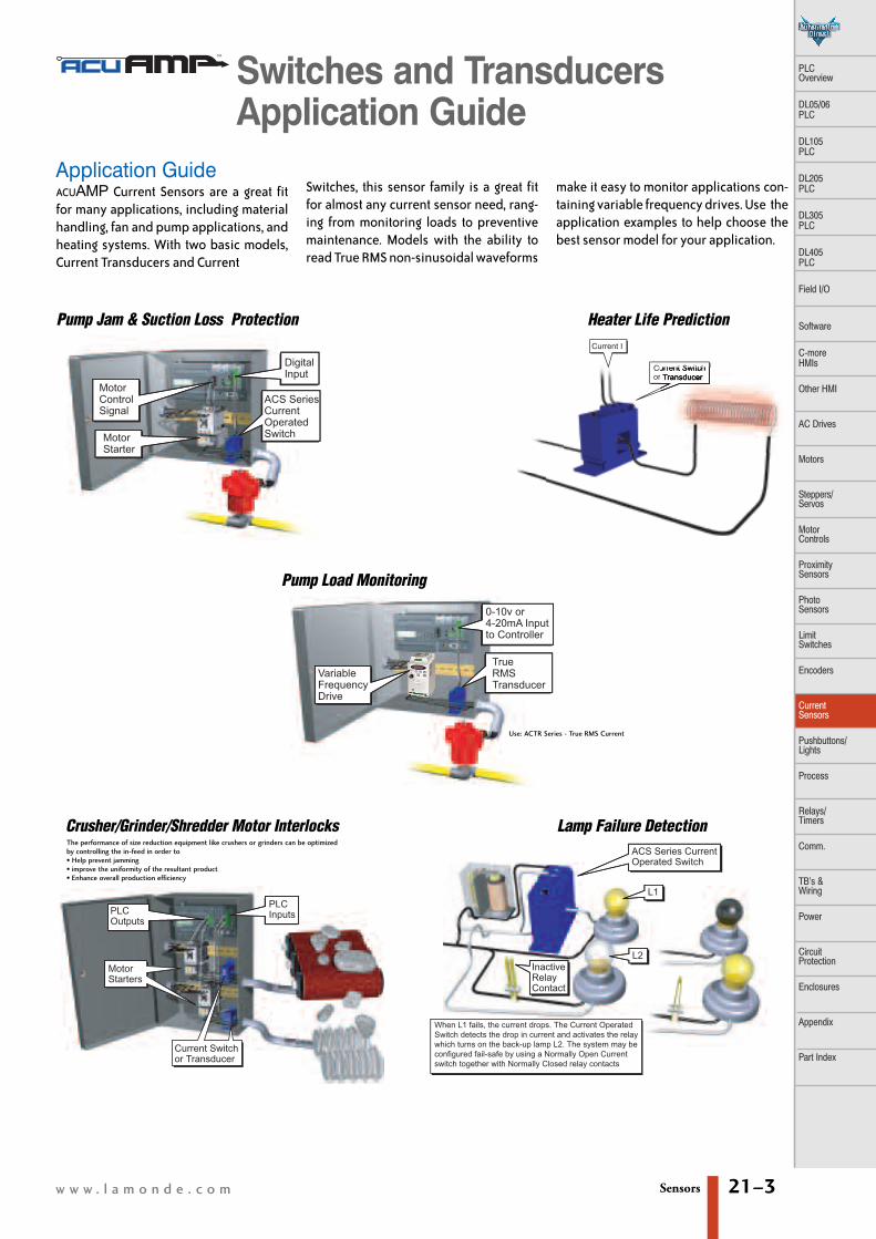
Pump Jam & Suction Loss Protection
Crusher/Grinder/Shredder Motor Interlocks
Heater Life Prediction
Lamp Failure Detection
Pump Load Monitoring
The performance of size reduction equipment like crushers or grinders can be optimizedby controlling the in-feed in order to• Help prevent jamming• improve the uniformity of the resultant product• Enhance overall production efficiency
Application GuideACUAMP Current Sensors are a great fitfor many applications, including materialhandling, fan and pump applications, andheating systems. With two basic models,Current Transducers and Current
Switches, this sensor family is a great fitfor almost any current sensor need, rang-ing from monitoring loads to preventivemaintenance. Models with the ability toreadTrueRMSnon-sinusoidalwaveforms
make it easy to monitor applications con-tainingvariable frequencydrives.Use theapplication examples to help choose thebest sensor model for your application.
MotorControlSignal
MotorStarter
DigitalInput
ACS SeriesCurrentOperatedSwitch
0-10v or 4-20mA Input to Controller
TrueRMSTransducer
VariableFrequencyDrive
PLCInputs
Current Switchor Transducer
MotorStarters
PLCOutputs
ACS Series CurrentOperated Switch
L1
L2InactiveRelayContact
When L1 fails, the current drops. The Current Operated Switch detects the drop in current and activates the relay which turns on the back-up lamp L2. The system may be configured fail-safe by using a Normally Open Current switch together with Normally Closed relay contacts
Use: ACTR Series - True RMS Current

0 17 3 7 - 8 2 4 6 0 0Sensors21–4
ACT current transducers combine a currenttransformer and signal conditioner into asingle package. The ACT series hasjumper-selected current input ranges andindustry standard 4-20 mA or0-10 VDC outputs. The ACT series isdesigned for application on ‘linear’ orsinusoidal AC loads and is compatible withmost PLCs, data loggers and SCADAsystems. Full-scale input ranges are user-selectable from 2A to 200 A. This series isavailable in split-core or fixed-coremodels.
ApplicationsAutomation Systems
• Analog current reading for remotemonitoring and software alarms
Data Loggers• Self-powered transducer helps conservedata logger batteries
• Split-core enclosures make using portabledata loggers easy
Panel Meters• Simple connection displays powerconsumption or other motor status
Features• Five-year Warranty• 4-20 mA or 0-10 VDC outputs• Use up to 14 AWG copper wires• Factory matched and calibrated singlepiece transducer is more accurate than tra-ditional two-piece field installed products
• Average responding algorithm gives anRMS output on pure sine waves. Perfect forconstant speed (linear) loads or On/Offloads
• Jumper-selectable input ranges allowend-users to tailor sensing ranges andimproves the odds of having the rightrange for the job
• Output is magnetically isolated from theinput for safety and to eliminate voltagedrop
Agency ApprovalsUL, cUL, CE approvals accepted worldwide
ACT Series Specifications-10 Models -42L Models
Power Supply Self-powered 24 VDC loop nominal, (40 VDC max) Loop-powered
Output Signal 0 - 10 VDC 4 - 20 mA, Loop-powered
Output Limit 15 VDC 32 mA
Accuracy 1% full scale 1% full scale
Response Time(10-90% step change) 100 ms 300 ms
Input Ranges Field selectable from 0 - 200 A
Sensing Aperture --FF ccoorree:: 0.75” (19 mm) diameter; --SS ccoorree:: 0.85” (21.6 mm) sq.
Isolation Voltage UL listed to 1,270VAC. Tested to 5,000 VAC (1 minute max)
Frequency Range (for sinusoidal waveforms) 50 to 60 Hz 20 to 100 Hz
Case UL 94V-0 flammability rated
EnvironmentalTemperature -4 to 122°F (-20 to 50°C)
Humidity 0 to 95% RH, non-condensing
Agency Listings UL listed 508, UL file E222847, CE approved
ACT Series Current TransducersPart Number Description Pcs/Pkg Wt/lbACT050-10-F AC current transducer, 0-10 VDC output, fixed core 1 0.30
ACT050-10-S AC current transducer, 0-10 VDC output, split core 1 0.38
ACT200-10-F AC current transducer, 0-10 VDC output, fixed core 1 0.30
ACT200-10-S AC current transducer, 0-10 VDC output, split core 1 0.38
ACT005-42L-F AC current transducer, 4-20mA output, fixed core 1 0.30
ACT005-42L-S AC current transducer, 4-20mA output, split core 1 0.35
ACT050-42L-F AC current transducer, 4-20mA output, fixed core 1 0.30
ACT050-42L-S AC current transducer, 4-20mA output, split core 1 0.35
ACT200-42L-F AC current transducer, 4-20mA output, fixed core 1 0.30
ACT200-42L-S AC current transducer, 4-20mA output, split core 1 0.35
AccessoriesDRA-2 DIN rail adapters, 1.69”x0.39”x0.75” (43x10x19 mm) 2 0.40
ACT Series Current Transducers
Maximum Input Ranges
Model Range Maximum Input AmpsContinuous 6 Sec max 1 Sec max
ACT0050 to 2A 80 125 2500 to 5A 100 125 250
ACT0500 to 10A 80 125 2500 to 20A 110 150 3000 to 50A 175 215 400
ACT2000 to 100A 200 300 6000 to 150A 300 450 8000 to 200A 400 500 1000

OperatorInterfacePanel Input to
Controller
Transducer,even on VFDsor SCRs
Sensorsw w w . l a m o n d e . c o m
PLC Overview
DL05/06 PLC
DL105 PLC
DL205 PLC
DL305 PLC
DL405 PLC
Field I/O
Software
C-more HMIs
Other HMI
AC Drives
Motors
Steppers/Servos
Motor Controls
ProximitySensors
Photo Sensors
Limit Switches
Encoders
CurrentSensors
Pushbuttons/Lights
Process
Relays/Timers
Comm.
TB’s & Wiring
Power
CircuitProtection
Enclosures
Appendix
Part Index
21–5
2(+)1(–)Output
Range Jumper
(+)(–)24 VDC Power
(+)(–)
Load(Controller,Meter, etc.)
2(+)1(–)Output
Range Jumper
4–20mA Option
0–10 VDC Option >1Mq Recommended100k q Acceptable
Notes: Captive screw terminals.
Observe polarity.
0 500250 1000750Total Loop Impedance (Ohms)
252015105
) CD V( rewo P pooL
Operating Range
VL = 12VDC + (RL× 0.020A)where VL = Minimum Loop Supply
RL = Total Loop Resistance (Ohms)
Power Supply (4–20mA output only)
Connections
Use 12-22 AWG solid or stranded
Terminals are #6 screws.
Connections
ACT Series Current Transducers
3.50 "88.9mm
3.03 "77.0mm
0.93 "23.6mm
Ø 0.19 "4.8mm 2.40 "
61.0mm
2.18 "55.4mm
Ø 0.74 "19mm
-F Style
0 .8 6"2 1 .7 m m
0 .8 5"2 1 .7 m m
2 .2 5"5 7 .2 m m
3 .5 3"8 9 .7 m m
1 .1 9"3 0 .2 m m
2 .4 0"6 1 m m
3 .0 4"7 7 .3 m m
Ø 0 .1 9"4 .8 m m
-S Style
Dimensions (in/mm)

0 17 3 7 - 8 2 4 6 0 0Sensors21–6
The ACTR transducers combine a currenttransformer and a True RMS signal condi-tioner into one. These transducers areavailable in 4 to 20 mA output only.
The ACTR Series provides True RMS outputon distorted waveforms found on VFD orSCR outputs, and on linear loads in “noisy”power environments. Choose from fixed orsplit-core style.
ApplicationsVFD Controlled Loads
• VFD output indicates how the motor andattached load are operating
SCR Controlled Loads• Accurate measurement of phase anglefired or burst fired (time proportioned)SCRs. Current measurement gives fasterresponse than temperature measurement
Switching Power Supplies andElectronic Ballasts
• True RMS sensing is the most accurate wayto measure power supply or ballast inputpower
Features• Five-year Warranty• 4-20 mA output only• True RMS technology is accurate on distort-ed waveforms like VFD or SCR outputs
• Choice of jumper-selectable rangesreduces inventory and eliminates zero andspan pots.
• Output is magnetically isolated from theinput for safety and eliminates voltagedrop
Agency ApprovalsUL, cUL, CE approvals accepted worldwide
ACTR Series Current TransducersPart Number Description Pcs/Pkg Wt/lbACTR005-42L-F AC current transducer with true RMS, 4-20mA output, fixed core 1 0.30
ACTR005-42L-S AC current transducer with true RMS, 4-20mA output, split core 1 0.36
ACTR050-42L-F AC current transducer with true RMS, 4-20mA output, fixed core 1 0.30
ACTR050-42L-S AC current transducer with true RMS, 4-20mA output, split core 1 0.36
ACTR200-42L-F AC current transducer with true RMS, 4-20mA output, fixed core 1 0.30
ACTR200-42L-S AC current transducer with true RMS, 4-20mA output, split core 1 0.36
AccessoriesDRA-2 DIN rail adapters, 1.69”x0.39”x0.75” (43x10x19 mm) 2 0.40
ACTR Series Specifications-42L Models
Power Supply 24 VDC nominal, (12 - 40 VDC) Loop-powered
Output Signal 4 -20 mA, loop-powered, true RMS
Output Limit 23 mA
Accuracy 1% full scale
Response Time (10-90% step change) 600 ms
Input Ranges Field selectable from 0 - 200 A
Sensing Aperture --FF ccoorree:: 0.75” (19 mm) dia.--SS ccoorree:: 0.85” (21.6 mm) sq.
Isolation Voltage UL listed to 1,270VAC. Tested to 5,000 VAC (1 minute max)
Frequency Range 10 to 400 Hz
Case UL 94V-0 flammability rated
EnvironmentalTemperature –4 to 122°F (–20 to 50°C)
Humidity 0 to 95% RH, non-condensing
Agency Listings UL listed 508, UL file E222847, CE approved
Maximum Input Ranges
Model Range Maximum Input AmpsContinuous 6 Sec max 1 Sec max
ACTR0050 to 2A 80 125 2500 to 5A 100 125 250
ACTR0500 to 10A 80 125 2500 to 20A 110 150 3000 to 50A 175 215 400
ACTR2000 to 100A 200 300 6000 to 150A 300 450 8000 to 200A 400 500 1000
ACTR Series Current Transducers
Why use ACTR transducers? The current waveform of a typical linearload is a pure sine wave. In VFD and SCRapplications, however, output waveformsare rough approximations of a sine wave,and are non-sinusoidal.
There are numerous spikes and dips ineach cycle. ACTR transducers use a math-ematical algorithm called “True RMS,”which integrates the actual waveform overtime. The output is the amperage compo-nent of the true power (heating value) ofthe AC current waveform.
True RMS is the only way to accuratelymeasure distorted AC waveforms. SelectACTR transducers for nonlinear loads or in“noisy” power environments.

Sensorsw w w . l a m o n d e . c o m
PLC Overview
DL05/06 PLC
DL105 PLC
DL205 PLC
DL305 PLC
DL405 PLC
Field I/O
Software
C-more HMIs
Other HMI
AC Drives
Motors
Steppers/Servos
Motor Controls
ProximitySensors
Photo Sensors
Limit Switches
Encoders
CurrentSensors
Pushbuttons/Lights
Process
Relays/Timers
Comm.
TB’s & Wiring
Power
CircuitProtection
Enclosures
Appendix
Part Index
21–7
Dimensions (in/mm)
ACTR Series Current Transducers
2(+)Output
Range Jumper
24 VDC Power(+)(–)
Load(Controller,Meter, etc.)
4–20mA Option
1000Total Loop Impedance (Ohms)
3227221712
(V
DC
) rewoP pooL
Operating Range
Notes:Deadfront captive screwterminals (–F case)12–22 AWG solid or strandedObserve polarity
Power Supply (4–20 mA output only)
VL = 12VDC + (RL× 0.020A)where VL = Minimum Loop Supply
RL = Total Loop Resistance (Ohms)
3.50 "88.9mm
3.03 "77.0mm
0.93 "23.6mm
Ø 0.19 "4.8mm 2.40 "
61.0mm
2.18 "55.4mm
Ø 0.74 "19mm
Connections
-F Style-S Style
250 7505000
(+)(–)
1(–)
0.85"21.6mm
0.85"21.6mm
2.25"57.2mm
3.53"89.7mm
3.04"77.2mm
1.18"30mm
0.45"11.4mm
2.40"31mm
Ø 0.19"4.83mm
Connections
VariableFrequencyDrive
OperatorInterfacePanel Input to
Controller
True RMSTransducer,even on VFDsor SCRs
0.86"
0.85"
2.25"
3.53"
3.04"
1.18"
0.45"
2.40"
Ø 0.19"
Range Jumper
3.50"88.9mm
3.03"76.9mm
0.93"23.6mm
Ø 0.19"4.8mm 2.40"
61.8mm
2.18"55.4mm
Ø 0.74"19mm
RangeJumper
-S Style-F Style

0 17 3 7 - 8 2 4 6 0 0Sensors21–8
ACS150 Series current operated switchescombine a current transformer, signalconditioner and limit alarm into a singlepackage for use in monitoring or proof ofoperation applications. Offering anadjustable setpoint range of 1 to 150amps and universal, solid-state outputs,the self-powered ACS150 can be tailoredto provide accurate and dependabledigital indication of over-current condi-tions across a broad range of applica-tions. The ACS150 is available infixed-core and split-core models.
ApplicationsElectronic Proof of Flow
• Current operated switch eliminates theneed for multiple pipe or duct penetrations
• More reliable than electromechanicalpressure or flow switches
Conveyors• Detect jams and overloads; useful wheninterlocking multiple conveyor sections
Heating Circuits• Detect ON/OFF status; faster responsetimes than with temperature sensors
Loss of Load Detective• Detect belt or coupling breaks with fastresponse times
Lighting Circuits• Easier and faster than photocells
Features• Five-year warranty• N.O. Universal Outputs 0.15 A @ 240 VAC/VDC
• Status LED provides visual indication ofsetpoint trip and contact action
• Self-powered operation cuts installationtime and operating costs
• Field-adjustable trip points speed start-upand allow for tailored operation
• Choose either split-core or fixed-coreenclosure style. Split-core packages alloweasy installation on existing systems ;fixed-core enclosures offer more compactpackage for OEM or new installations
• Integral mounting feet offer secure mounting
Agency ApprovalsUL, cUL, CE approvals accepted worldwide
ACS150 Series SpecificationsPower Supply None - Self-powered
Output Isolated solid-state switch
Output Rating N.O. 0.15 A @ 240 VAC or VDC
Response Time 120 ms
Off State Leakage < 10 µA
Input Ranges Fixed-core: 1 to 150 A. Split-core: 1.75 to 150 A
Hysteresis 5% of Setpoint
Overload (1 second duration) 1,000 A
Isolation Voltage UL listed to 1,270VAC. Tested to 5,000 VAC (1 minute max)
Frequency Range 6 to 100 Hz
Case UL 94V-0 flammability rated
EnvironmentalTemperature -58 to 149°F (-50 to 65°C)
Humidity 0 to 95% RH, non-condensing
Agency Listings UL listed 508, UL file E222847, CE approved
ACS150 Current Operated SwitchesPart Number Description Pcs/Pkg Wt/lb
ACS150-AE-F N.O. AC/DC adjustable current switch in fixed core enclosure 1 0.30
ACS150-AE-S N.O. AC/DC adjustable current switch in split core enclosure 1 0.35
AccessoriesDRA-2 DIN rail adapters, 1.69”x0.39”x0.75” (43x10x19 mm) 2 0.40
ACS150 Series Switches
ACS150 Maximum Input Ranges
Type Range -Adjustable
Maximum Input Amps
Continuous 6 Sec max 1 Sec max
FFiixxeedd CCoorree 1 - 150 A 150 400 1000
SSpplliitt CCoorree 1.5 - 150 A 150 400 1000
ACS150 Minimum Load/MTBF
Minimum LoadOperating Current
MTBF (Mean Time BetweenFailure) x 10^6
**** 4.33 hours**** 4.33 hours** The AC/DC switch output has no specified minimum loadrequired to operate the output. There is a maximum resistance of 5 ohms across the output when the switch is “on”

Sensorsw w w . l a m o n d e . c o m
PLC Overview
DL05/06 PLC
DL105 PLC
DL205 PLC
DL305 PLC
DL405 PLC
Field I/O
Software
C-more HMIs
Other HMI
AC Drives
Motors
Steppers/Servos
Motor Controls
ProximitySensors
Photo Sensors
Limit Switches
Encoders
CurrentSensors
Pushbuttons/Lights
Process
Relays/Timers
Comm.
TB’s & Wiring
Power
CircuitProtection
Enclosures
Appendix
Part Index
21–9
2Output1Setpoint
Typical of Models with LED
SmartLEDR
3.50 "88.9mm
3.03 "77.0mm
0.93 "23.6mm
Ø 0.19 "4.8mm 2.40 "
61.0mm
2.18 "55.4mm
Ø 0.74 "19mm
-F Style
0.85 "21.6mm
0.85 "21.6mm
3.53 "89.7mm
2.40 "61mm
3.04 "77.2mm
Ø 0.19 "4.8mm
2.25 "57.2mm
1.19 "30.2mm
-S Style
Terminals are #6 screws.Use up to 14 AWG copper wire
LINE
Controller
Starter
DODigital
Out
DIDigital
In
FAN ON
NOT REQUIRED!
2nd Conduit, Wire, DP Switch, Pressure Tubing, Pipe Fitter, etc.
Motor
PerfectMatch for
AutomationSystems
S PMA
TIME
StartupInrush
Normal Operation Belt orCouplingBreaks
SPMA
TIME
StartupInrush
Normal Operation
Jam
MOTOROFF
Overload or JamUnderload or Status
Dimensions (in/mm)
Connections
ACS150 Series Switches
Motor Control Signal
MotorStarter
Digital Input
ACS SeriesCurrent Operated Switch
0.86"21.7mm
0.85"21.7mm
2.25"57.2mm
3.53"89.7mm
1.19"30.2mm
2.40"61mm
3.04"77.3mm
Ø 0.19"4.8mm
LED
Trip PointAdjust
3.50"88.9mm
3.03"76.9mm
0.93"23.6mm
Ø 0.19"4.8mm 2.40"
61.8mm
2.18"55.4mm
Ø 0.74"19mm
LEDSetpoint Adjust
-F Style -S Style

0 17 3 7 - 8 2 4 6 0 0Sensors21–10
ACS200 series current operated switchesprovide the same dependable status indi-cation as the ACS150 series, but withadded resolution. A choice of threejumper-selectable input ranges allows theACS200 to be tailored to an applicationand provides more precision in setpointadjustment. Self-powered, isolated solid-state relay outputs and multiple inputranges are standard features.
ApplicationsElectronic Proof of Flow
• Current operated switch eliminates theneed for multiple pipe or duct penetrations, lowering installed costs
• Solid-state technology more reliable thanelectromechanical pressure or flow switches
Conveyors• Detect jams and overloads; useful wheninterlocking multiple conveyor sections
Lighting, Heating Circuits• Detect ON/OFF status, easier to install andless expensive than photocell or tempera-ture sensor alternatives
Features• Five-year warranty• N.O. Universal Outputs 1A @ 240 VAC or 0.15 A @ 30 VDC
• Status LED provides visual indication ofsetpoint trip and contact action
• Self-powered operation cuts installationtime and operating costs
• Field-adjustable trip points speed start-upand allow for tailored operation
• Choose fixed-core or split-core enclosurestyle. Split-core allows easy installation onexisting systems; fixed-core offers morecompact package for OEM or new installa-tions
• Integral mounting feet provide securemounting
Agency ApprovalsUL, cUL, CE approvals accepted worldwide
ACS200 Series SpecificationsPower Supply None - Self-powered
Output Isolated solid-state switch
Output Rating N.O. AC: 1A @ 240 VACN.O. DC: 0.15A @ 30 VDC
Response Time 40 - 120 ms
Off State Leakage < 10 µA
Input Ranges Jumper selectable: Fixed-core: 1 to 175 A. Split-core: 1.75 to 200 A
Hysteresis low: 0.15A; mid: 0.3; high: 0.9A
Overload (1 second duration) low: 600 A; mid: 800 A; high: 1,200 A
Isolation Voltage UL listed to 1,270VAC. Tested to 5,000 VAC (1 minute max)
Frequency Range 6 to 100 Hz
Case UL 94V-0 flammability rated
EnvironmentalTemperature -58 to 149°F (-50 to 65°C)
Humidity 0 to 95% RH, non-condensing
Agency Listings UL listed 508, UL file E222847, CE approved
ACS200 Current Operated SwitchesPart Number Description Pcs/Pkg Wt/lb
ACS200-AA-F N.O. AC adjustable current switch, fixed core 1 0.40
ACS200-AA-S N.O. AC adjustable current switch, split core 1 0.40
ACS200-AD-F N.O. DC adjustable current switch, fixed core 1 0.40
ACS200-AD-S N.O. DC adjustable current switch, split core 1 0.40
Accessories DRA-2 DIN rail adapters, 1.69”x0.39”x0.75” (43x10x19 mm) 2 0.40
Maximum Input RangesRangeJumper
Range -Fixed Core
RangeSplit Core
Maximum Input Amps6 Sec max 1 Sec max
NONE 1 to 6 A 1.75 to 6 A 400 600
MID 6 to 40 A 6 to 40 A 500 800
HIGH 40 to 175 A 40 to 200 A 800 1200
Switching Delay
Delay LOW Range MID Range HIGH Range
ON Delay 0.23 sec max 0.05 sec max 0.03 sec max
OFF Delay 0.02 sec max 0.02 sec max 0.01 sec max
Hysteresis6% 4% 3%
ACS200 Series Switches
ACS200 Minimum Load/MTBF
PartNumber
Min. OperatingCurrent
MTBF (Mean TimeBetween Failure) x 10^6
AACCSS220000--AAAA--FF 20 mA 4.29 hoursAACCSS220000--AAAA--SS 20 mA 4.29 hoursAACCSS220000--AADD--FF 1 mA 4.39 hoursAACCSS220000--AADD--SS 1 mA 4.39 hours

Sensorsw w w . l a m o n d e . c o m
PLC Overview
DL05/06 PLC
DL105 PLC
DL205 PLC
DL305 PLC
DL405 PLC
Field I/O
Software
C-more HMIs
Other HMI
AC Drives
Motors
Steppers/Servos
Motor Controls
ProximitySensors
Photo Sensors
Limit Switches
Encoders
CurrentSensors
Pushbuttons/Lights
Process
Relays/Timers
Comm.
TB’s & Wiring
Power
CircuitProtection
Enclosures
Appendix
Part Index
21–11
2.18 "55.4mm
0.92 "23.4mm
Ø 0.55 "14mm
3.30 "83.8mm
2.75 "69.9mm
2.16 "54.9mm
Ø 0.19 "4.8mm
0.85 "21.6mm
0.85 "21.6mm
3.53 "89.7mm
2.40 "61mm
3.04 "77.2mm
Ø 0.19 "4.8mm
2.25 "57.2mm
1.19 "30.2mm
-F Style -S Style
Dimensions (in/mm)
Connections
Greatwith
Relay LogicControl
LINE
Controller
Starter
DODigital
Out
DIDigital
In
FAN ON
Motor
SPMA
TIME
StartupInrush
Normal Operation Belt orCouplingBreaks
SPM A
TIME
StartupInrush
Normal Operation
Jam
MOTOROFF
Overload or JamUnderload or Status
Setpoint Status LED
Output
InputRange Jumper
mid highlownone
Terminals are #6 screwsUse up to 14 AWG copper wire
ACS200 Series Switches
DigitalOutput
MotorStarter
Digital Input
ACS SeriesCurrent Operated Switch

0 17 3 7 - 8 2 4 6 0 0Sensors21–12
ACSX Series Switches
The ACSX series high-performancecurrent-operated switch has a field-adjustable time delay feature that mini-mizes nuisance trips during start-up andoperation. These switches are designed formotor status applications where setpointaccuracy and repeatability are critical andoffer a linear setpoint characteristic andconstant hysteresis.
ApplicationsMotor Protection
• Serves as an electronic proof-of-operation;detects current draw changes in motorswhen they encounter problems such aspumps running dry or impending bearing failure
• Non-intrusive; less expensive to installthan differential pressure flow sensors orthermal switches
• Much quicker response time than Class 10overload relays
High Inrush or TemporaryOverload Current
• Adjustable start-up/delay timer allows 0-15 second delay to eliminate nuisancetrips from high inrush or short overloadconditions
FeaturesStandard features include self-powering,jumper-selectable ranges and a choice ofoutputs and core styles
• Five-year warranty• Adjustable start-up/delay timer is field-adjustable from 0.2 to 15 seconds to eliminate nuisance alarms caused by start-up inrush or temporary overcurrentconditions.
• Choice of N.O. AC or AC/DC outputs:Contact ratings of 1.0A @ 240 VAC or universal outputs of 0.15A @ 240 VAC/VDCfor use with most standard motor controlsystems.
• Improved ease of installation and use: - 1.0A rating eliminates need for time delayrelay
- Self-powered, split-core models simplifyinstallation
- Status LED provides visual indication ofsetpoint trip and contact action
• Industrial grade performance - constanthysteresis and linear setpoint response forgreater accuracy
Agency ApprovalsUL, cUL Listed
CE approval pending
ACSX Series SpecificationsPower Supply None - Self-powered
Output Isolated solid-state switch
Output Rating N.O. AC: 1A @ 240 VACN.O. AC/DC: 0.15 A @ 240 VAC/VDC
Response Time Adjustable 0.2 to 15 seconds
Off State Leakage < 10 µA
Input Ranges Jumper Selectable: Fixed core: 1 to 175 ASplit core: 2 to 200 A
Hysteresis 5% constant
Overload (1 second duration)2 to 12 A Range: 600 A; 12 to 55 A Range: 800 A; 50 to 200 A Range: 1200 A
Isolation Voltage UL listed to 1,270VAC. Tested to 5,000 VAC (1 minute max)
Frequency Range 50 to 100 Hz
Case UL 94V-0 flammability rated
EnvironmentalTemperature 5 to 122°F (-15 to 50°C) operating temperature
Humidity 0 to 95% RH, non-condensing
Agency Listings UL listed 508, UL file E222847, CE approval pending
ACSX Current Operated SwitchesPart Number Description Pcs/Pkg Wt/lb
ACSX200-AA-F N.O. AC adjustable current switch, fixed core 1 0.30
ACSX200-AA-S N.O. AC adjustable current switch, split core 1 0.40
ACSX200-AE-F N.O. AC/DC adjustable current switch, fixed core 1 0.30
ACSX200-AE-S N.O. AC/DC adjustable current switch, split core 1 0.40
Accessories DRA-2 DIN rail adapters, 1.69”x0.39”x0.75” (43x10x19 mm) 2 0.40
Maximum Input Ranges
Type Range -Adjustable
Maximum Input AmpsContinuous 6 Sec max 1 Sec max
Fixed Core 1-175 A 150 400 1000Split Core 2-200 A 150 400 1000
ACSX200 Minimum Load/MTBFPartNumber
Minimum LoadOperating
MTBF (Mean TimeBetween Failure) x 10^6
AACCSSXX220000--AAEE--FF ** 4.33 hoursAACCSSXX220000--AAEE--SS ** 4.33 hoursAACCSSXX220000--AAAA--FF 20 mA 4.29 hoursAACCSSXX220000--AAAA--SS 20 mA 4.29 hours** The AC/DC switch output has no specified minimum loadrequired to operate the output. There is a maximum resistance of 5 ohms across the output when the switch is “on.”

Sensorsw w w . l a m o n d e . c o m
PLC Overview
DL05/06 PLC
DL105 PLC
DL205 PLC
DL305 PLC
DL405 PLC
Field I/O
Software
C-more HMIs
Other HMI
AC Drives
Motors
Steppers/Servos
Motor Controls
ProximitySensors
Photo Sensors
Limit Switches
Encoders
CurrentSensors
Pushbuttons/Lights
Process
Relays/Timers
Comm.
TB’s & Wiring
Power
CircuitProtection
Enclosures
Appendix
Part Index
21–13
ACSX Series Switches
SPMA
TIME
StartupInrush
Normal Operation Belt or CouplingBreaks
SPMA
TIME
StartupInrush
Normal Operation
Jam
MOTOR OFF
tt
LINE
Controller
Starter
DODigital
Out
DIDigital
In
FAN ON
NOT REQUIRED!
2nd Conduit, Wire, DP Switch, Pressure Tubing, Pipe Fitter, etc.
Motor
PerfectMatch for
AutomationSystems
1.93"49mm
2.18"55.4mm
0.6"15mm
0.931"23.7mm
2.433"61.8mm
3.53"89.7mm
1.506"38.3mm
3.08"78mm
1.5"39mm
0.125"3.2mm
0.75"19mm
dia.
0.967"24.56mm
0.17"4.5mm int. dia.Typical of 2
LED
2.25"57.2mm
2.4"61mm
0.854"21.7mm
0.857"21.7mm
0.72"18.3mm
0.52"13mm
0.19"4.5mm dia.Typical of 2
0.36"9.1mm
0.52"13mm
2.4"61mm
3.53"89.7mm
3.044"77.3mm
1.18"30mm
0.125"3.2mm
-F Style -S Style
Dimensions (in/mm)
RangengTimeDelay
S
OutputOOutppuut
mid
highh
Use up to 14 AWG copper wire
Connections
DigitalOutput
MotorStarter
Digital Input
ACSX SeriesCurrent Operated Switch
0.86"
0.85"
2.25"
3.53"
3.04"
1.18"
0.45"
2.40"
Ø 0.19"
Range Jumper
LED
Trip PointAdjust Time Delay Adjust
-S Style