Embed Size (px)
Citation preview
• Procesos electroquímicos para:
• Eficientar el uso de energía
• Tratamiento de contaminantes
• Electrogeneración de luz
Proyectos de Investigación Jorge Ibáñez Cornejo
(JIC)
PROCESOS SIMULTÁNEOS
• En electroquímica es frecuente que se use sólo una de las dos reacciones de la celda para producir una sustancia de interés.
• Por ello estamos trabajando en procesos en donde se usa la electricidad en ambos electrodos para llevar a cabo una reacción útil
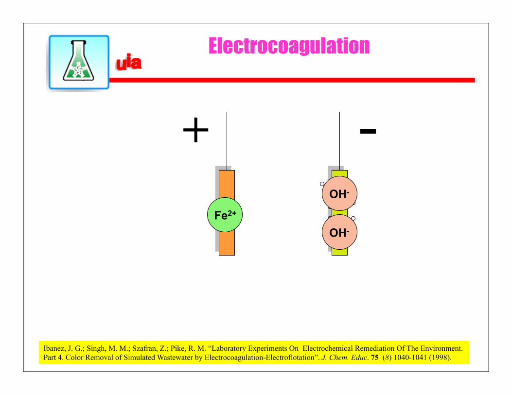
Electrocoagulation
- + Fe2+
OH-
OH-
Ibanez, J. G.; Singh, M. M.; Szafran, Z.; Pike, R. M. “Laboratory Experiments On Electrochemical Remediation Of The Environment. Part 4. Color Removal of Simulated Wastewater by Electrocoagulation-Electroflotation”. J. Chem. Educ. 75 (8) 1040-1041 (1998).
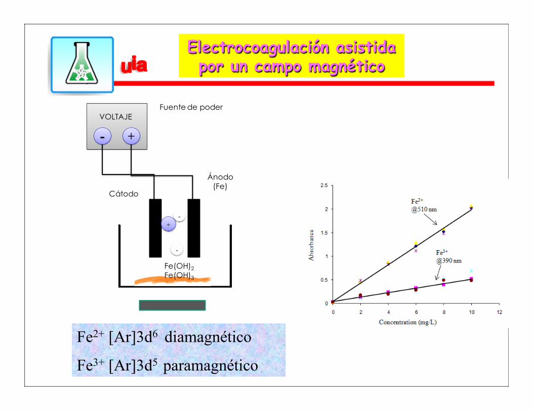
Electrocoagulación asistida por un campo magnético
Fe2+ [Ar]3d6 diamagnético
Fe3+ [Ar]3d5 paramagnético
+-VOLTAJE
Fuente de poder
Ánodo(Fe)
Cátodo
+-
-
Fe(OH)2
Fe(OH)3
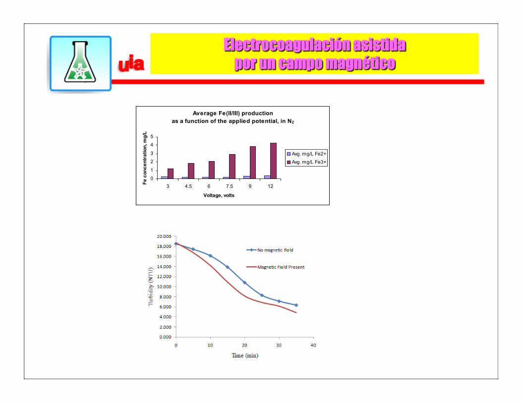
Electrocoagulación asistida por un campo magnético
Average Fe(II/III) production as a function of the applied potential, in N2
0
1
2
3
4
5
3 4.5 6 7.5 9 12
Voltage, volts
Fe c
once
ntra
tion,
mg/
L
Avg. mg/L Fe2+
Avg. mg/L Fe3+
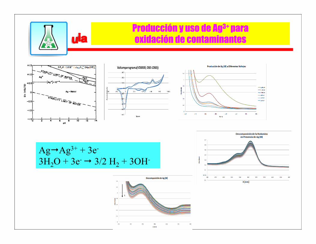
Producción y uso de Ag3+ para oxidación de contaminantes
Ag"Ag3+ + 3e- 3H2O + 3e- " 3/2 H2 + 3OH-
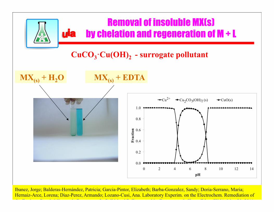
Removal of insoluble MX(s) by chelation and regeneration of M + L
MX(s) + H2O MX(s) + EDTA
0.0
0.2
0.4
0.6
0.8
1.0
0 2 4 6 8 10 12 14
Fraction
pH
Cu Cu CO (OH) (s) CuO(s)2+22 3
CuCO3·Cu(OH)2 - surrogate pollutant
Ibanez, Jorge; Balderas-Hernández, Patricia; Garcia-Pintor, Elizabeth; Barba-Gonzalez, Sandy; Doria-Serrano, Maria; Hernaiz-Arce, Lorena; Diaz-Perez, Armando; Lozano-Cusi, Ana. Laboratory Experim. on the Electrochem. Remediation of the Environ. Part 9. Microscale Recovery of a Soil Metal Pollutant and its Extractant. J. Chem. Educ. (Web): May 20, 2011.
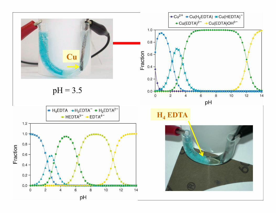
H4 EDTA
Cu
pH = 3.5
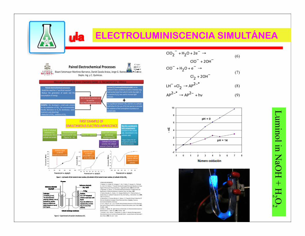
Paired Electrochemical Processes
Paired electrochemical processes:-‐ Avoid the need for a “sacrificial reaction”-‐ Reduce the generation of waste and theconsumption of energy
EXAMPLE: We developed a small–scale processfor the production of ClO2. (An environmentally-‐friendly alternative to Cl2 for disinfection, watertreatment, pulp bleaching)+ Reduction of ClO3
-‐, oxidation of ClO2-‐
Both electrodic reactions can be used for
ELECTROLUMINISCENCE (ECL)
Luminol (2,3-‐aminophthalohydrazide) can be oxidized in basic conditions to yield a relatively long-‐lived excited state from which it emits blue light. A co reactant (H2O2) was used to increase light emission.
The equilibrium between ClO2-‐ and ClO-‐ at a cathode
could allow for the use of this last species to provoke the oxidation of the luminophore to produce an excited state.
The equilibrium between ClO2-‐ and ClO-‐ at a cathode
could allow for the use of this last species to provoke the oxidation of the luminophore to produce an excited state.
+
FIRST EXAMPLE OF SIMULTANEOUS ELECTROLUMINISCENCE
Study of individual processses (i.e.,
conditions for ECL in cathode and anode)
Study of individual processses (i.e.,
conditions for ECL in cathode and anode)
Characterization ofluminol and ClO-‐ (LSV)
(Figures 1a – 1c)
Characterization ofluminol and ClO-‐ (LSV)
(Figures 1a – 1c)Obtain ECL separatelyObtain ECL separately
Couple both processesand attempt
simultaneous ECL
Couple both processesand attempt
simultaneous ECL
Cathodic ECL is more sensitive; the cathodic
potenial is fixed at -‐200 mV
Cathodic ECL is more sensitive; the cathodic
potenial is fixed at -‐200 mV
Blue ECL is produced in both compartments (constant in the anodic side, intermittent in the cathodic side).
* Figure 2 shows the cell arrangement used for the simultaneous process.
Blue ECL is produced in both compartments (constant in the anodic side, intermittent in the cathodic side).
* Figure 2 shows the cell arrangement used for the simultaneous process.
0
50
100
150
200
250
300
350
0 200 400 600 800 1000
Potential (mV vs. Ag/AgCl)
Cu
rre
nt
(µA
)
-21.05
-16.05
-11.05
-6.05
-1.05
-800 -700 -600 -500 -400 -300 -200 -100 0
Potential (mV vs. Ag/AgCl)
Cu
rren
t (µ
A)
-60
-50
-40
-30
-20
-10
0
-1000 -800 -600 -400 -200 0 200 400
Potential (mV vs. Ag/AgCl)
Cu
rre
nt
(µA
)
Figure 1 – (a) Anodic LSV for luminol in basic medium, (b) cathodic LSV for luminol in basic medium, (c) cathodic LSV for ClO2-‐.
0
50
100
150
200
250
300
350
0 200 400 600 800 1000
Potential (mV vs. Ag/AgCl)
Cu
rre
nt
(µA
)
-21.05
-16.05
-11.05
-6.05
-1.05
-800 -700 -600 -500 -400 -300 -200 -100 0
Potential (mV vs. Ag/AgCl)
Cu
rren
t (µ
A)
-60
-50
-40
-30
-20
-10
0
-1000 -800 -600 -400 -200 0 200 400
Potential (mV vs. Ag/AgCl)
Cu
rre
nt
(µA
)
Figure 1 – (a) Anodic LSV for luminol in basic medium, (b) cathodic LSV for luminol in basic medium, (c) cathodic LSV for ClO2-‐.
Oxidation signalat 300 mV
(should occur at anode)
Oxidation signalat 300 mV
(should occur at anode)
Reduction signalat -‐450 mV
(should NOT occurat the cathode)
Reduction signalat -‐450 mV
(should NOT occurat the cathode)
Reduction signal.Starts at -‐200 mV(should occur at
cathode).
Reduction signal.Starts at -‐200 mV(should occur at
cathode).
Reference electrode(Ag / AgCl)
Pt gauze
Reference electrode(Ag/AgCl)
Pt flag
Cationic Exchange membrane
Catholyte:1 M NaClO2 (5 mL)*As electrochemicalreduction initiated, 2 mL ofluminol/H2O2 solution(same as anolyte) wasadded dropwise on top ofthe Pt gauze.
Anolyte:5.6 x 10-‐6 M luminolsolution made basic withNaOH.H2O2 was added as co-‐reactant (30 μL of 10 % H2O2 in 5 mL of testsolution)
Figure 2 – Experimental cell used for simultaneous ECL.
Reference electrode(Ag / AgCl)
Pt gauze
Reference electrode(Ag/AgCl)
Pt flag
Cationic Exchange membrane
Catholyte:1 M NaClO2 (5 mL)*As electrochemicalreduction initiated, 2 mL ofluminol/H2O2 solution(same as anolyte) wasadded dropwise on top ofthe Pt gauze.
Anolyte:5.6 x 10-‐6 M luminolsolution made basic withNaOH.H2O2 was added as co-‐reactant (30 μL of 10 % H2O2 in 5 mL of testsolution)
Pt gauze
Reference electrode(Ag/AgCl)
Pt flag
Cationic Exchange membrane
Pt gauze
Reference electrode(Ag/AgCl)
Pt flag
Cationic Exchange membrane
Catholyte:1 M NaClO2 (5 mL)*As electrochemicalreduction initiated, 2 mL ofluminol/H2O2 solution(same as anolyte) wasadded dropwise on top ofthe Pt gauze.
Anolyte:5.6 x 10-‐6 M luminolsolution made basic withNaOH.H2O2 was added as co-‐reactant (30 μL of 10 % H2O2 in 5 mL of testsolution)
Figure 2 – Experimental cell used for simultaneous ECL.
Biaani Sotomayor Martínez-‐Barranco, Daniel Zavala Araiza, Jorge G. Ibanez Depto. Ing. y C. Químicas.
Mexican Microscale & Green Chemistry Center. U. Iberoamericana – México
LITERATURE REFERENCES1. Paddon, C.A.; Atobe, M.; Fuchigami, T.; He, P.; Watts, P.; Hasswel, S.J.; Pritchard, G.J.; Bull, S.D.; Marken, F. Towards Paired and Coupled Electrode Reactions for Clean Organic Microreactor Electrosyntheses, J. Appl Electrochem, 2005, 36, 617-‐634.2. Rajeshwar, K.; Ibanez, J. G. Environmental Electrochemistry: Fundamentals and Applications in Pollution Abatement. Academic Press, San Diego, 1997.3. Gomez-‐Gonzalez, A.;. Ibanez, J. G.; Vasquez-‐Medrano, R. C.; Paramo-‐Garcia, U.; Zavala-‐Araiza, D. Cathodic Production of ClO2 from NaClO3, J. Electrochem. Soc. 2009,156 (7), E113-‐E117.4. Mena-‐Brito, R.; Terrazas-‐Moreno, S.; Ibanez, J. G. Towards A Green Production Of Chlorine Dioxide By Convergent Paired Electrosynthesis. (In press, FreseniusEnvironmental Bulletin, Germany).5. Liu, X.; Jiang, H.; Lei, J.; Ju, H. Anodic Electrochemiluminescence of CdTe Quantum Dots and its Energy Transfer for Detection of Catechol Derivatives, Anal. Chem. 2007, 79, 8055 -‐ 8060.6. Bolton, E.; Richter, M.; Light Emission at Electrodes: An ElectrochemiluminescenceDemonstration”, J. Chem. Ed., 2001, 78, 641 – 643.7. Kumala, S.; Ala – Kleme, T.; Papkovsky, D.; Loikas, K. Cathodic ElectrogeneratedChemiluminescence of Luminol at Disposable Oxide – covered Aluminum Electrodes”, Anal. Chem. 1998, 70, 1112 – 1118.
−+−
→−++−
2OHClO
2eO2H2ClO (6)
−+
→−++−
2OH2Cl
eO2HClO (7)
*2AP2ClLH −→+− (8)
hν2AP*2AP +−→− (9)
ELECTROLUMINISCENCIA SIMULTÁNEA Lum
inol in NaO
H + H
2 O2
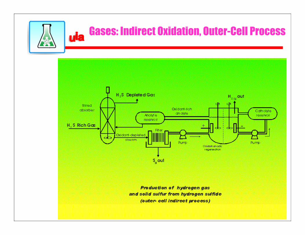
Gases: Indirect Oxidation, Outer-Cell Process
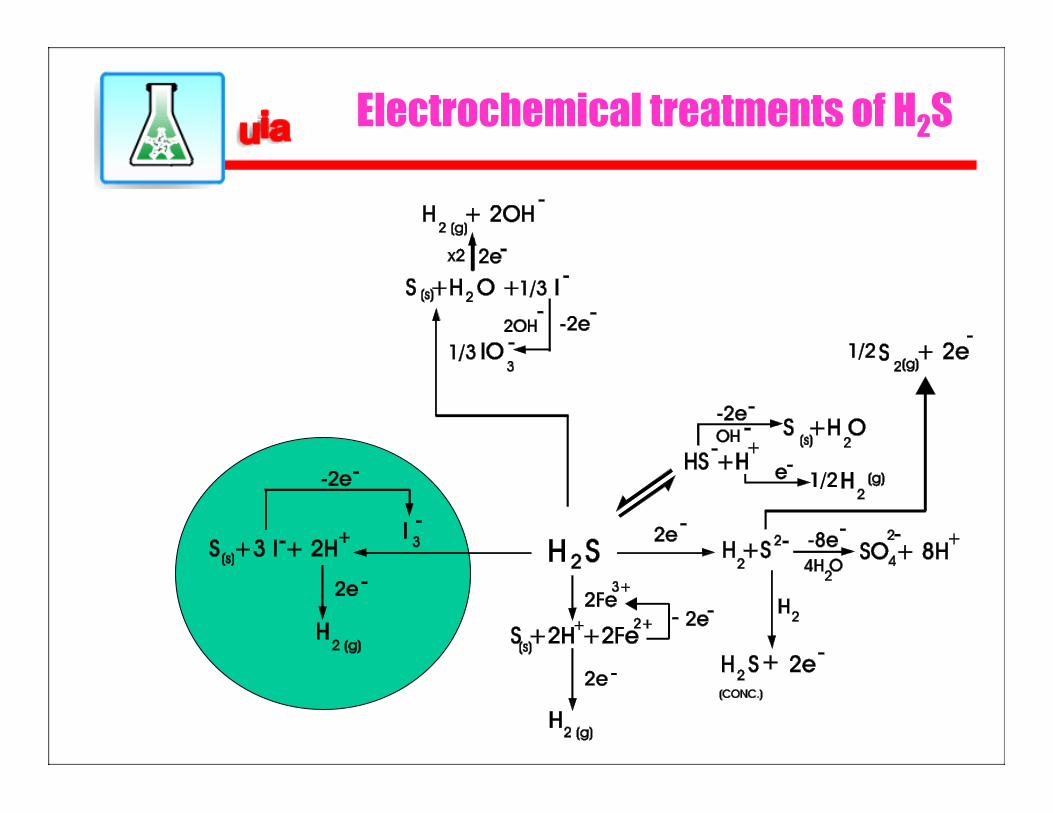
Electrochemical treatments of H2S
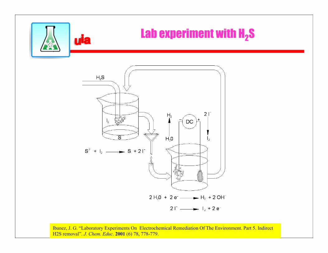
Lab experiment with H2S
Ibanez, J. G. “Laboratory Experiments On Electrochemical Remediation Of The Environment. Part 5. Indirect H2S removal”. J. Chem. Educ. 2001 (6) 78, 778-779.
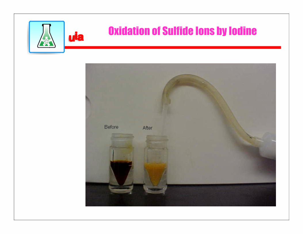
Oxidation of Sulfide Ions by Iodine
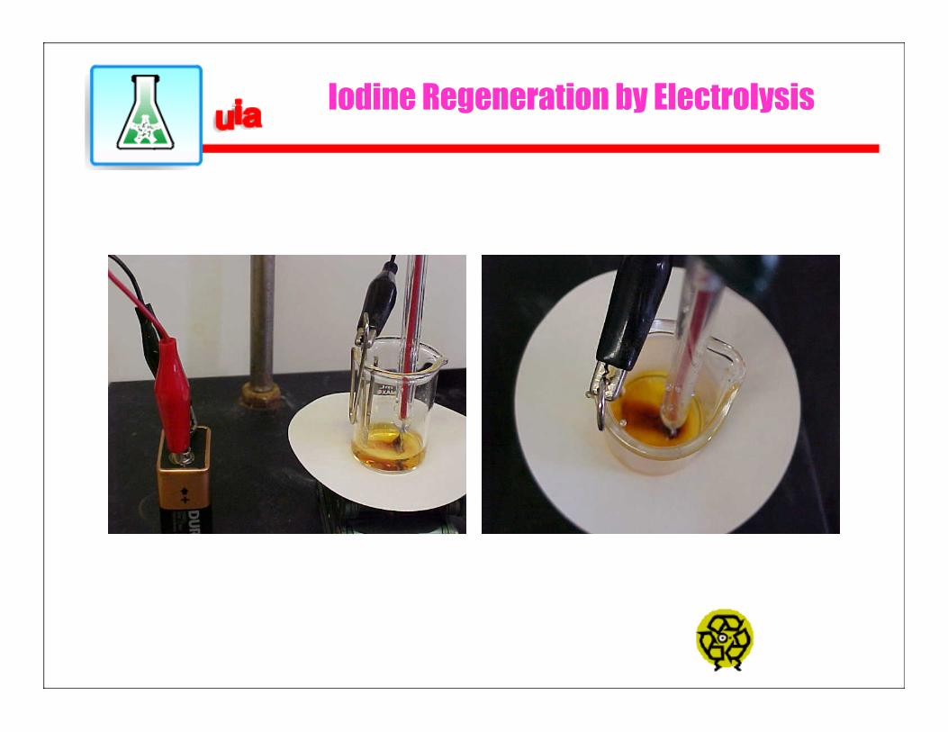
Iodine Regeneration by Electrolysis
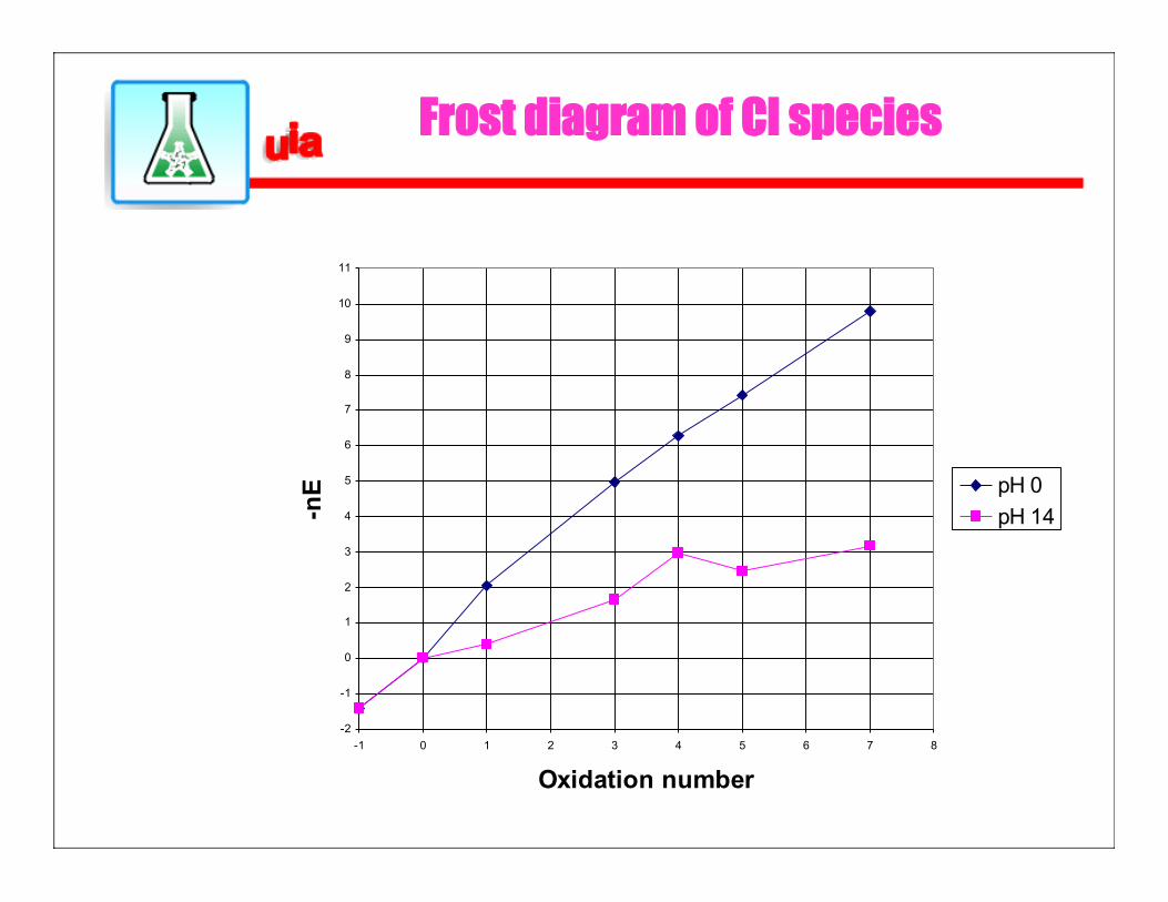
Frost diagram of Cl species
-2
-1
0
1
2
3
4
5
6
7
8
9
10
11
-1 0 1 2 3 4 5 6 7 8
Oxidation number
-nE pH 0
pH 14
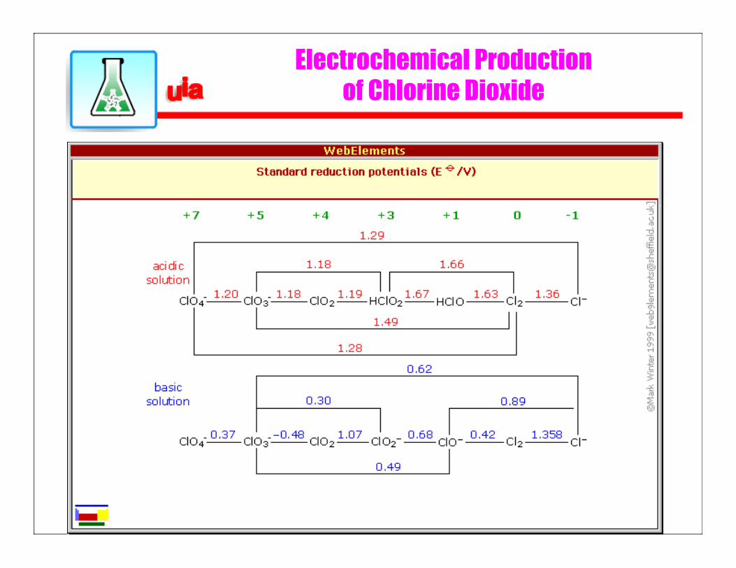
Electrochemical Production of Chlorine Dioxide
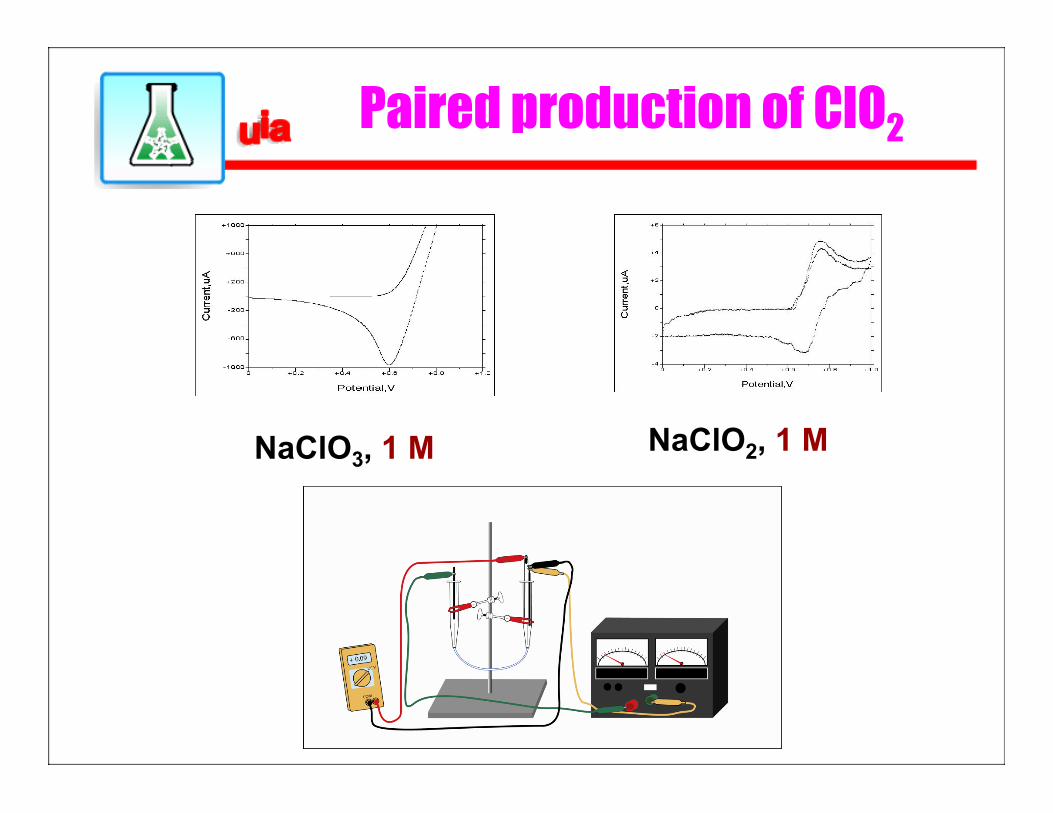
Paired production of ClO2
NaClO3, 1 M NaClO2, 1 M
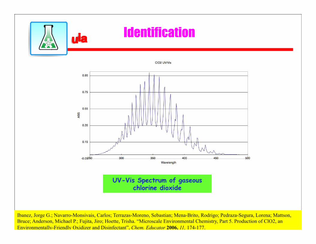
Identification
UV-Vis Spectrum of gaseous chlorine dioxide
Ibanez, Jorge G.; Navarro-Monsivais, Carlos; Terrazas-Moreno, Sebastian; Mena-Brito, Rodrigo; Pedraza-Segura, Lorena; Mattson,
Bruce; Anderson, Michael P.; Fujita, Jiro; Hoette, Trisha. “Microscale Environmental Chemistry, Part 5. Production of ClO2, an Environmentally-Friendly Oxidizer and Disinfectant”, Chem. Educator 2006, 11, 174-177.
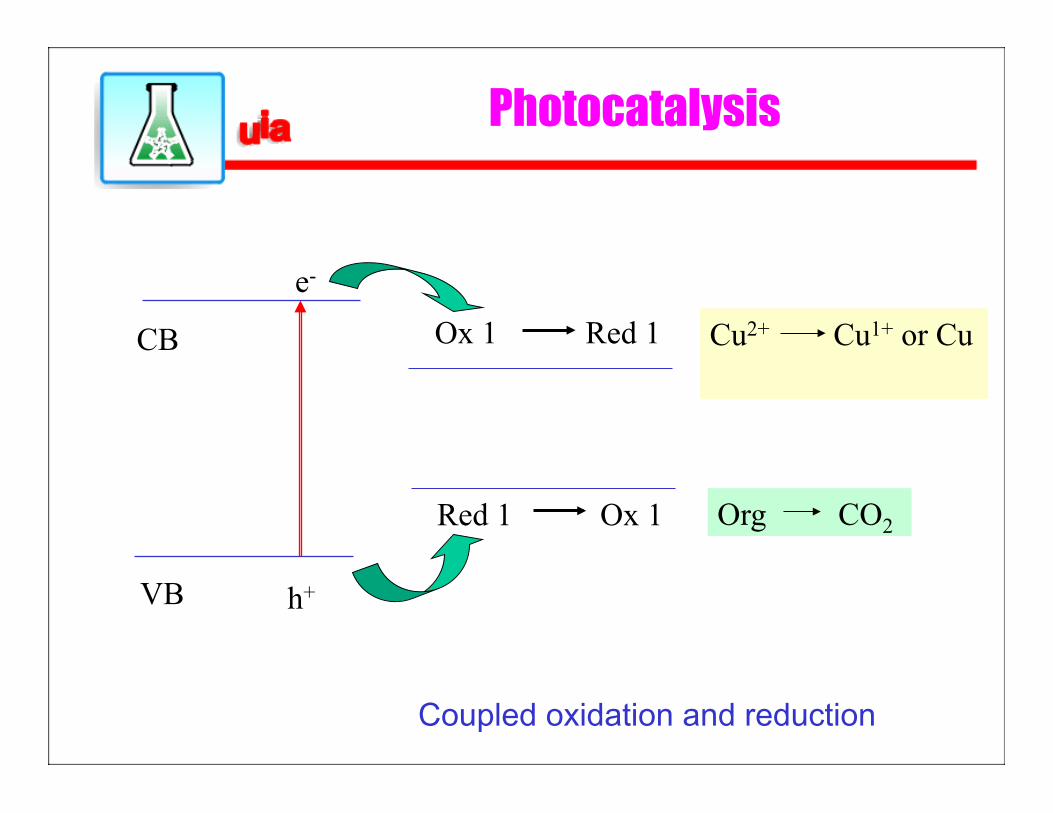
Photocatalysis
Cu2+ Cu1+ or Cu CB
VB
e-
h+
Ox 1 Red 1
Red 1 Ox 1 Org CO2
Coupled oxidation and reduction
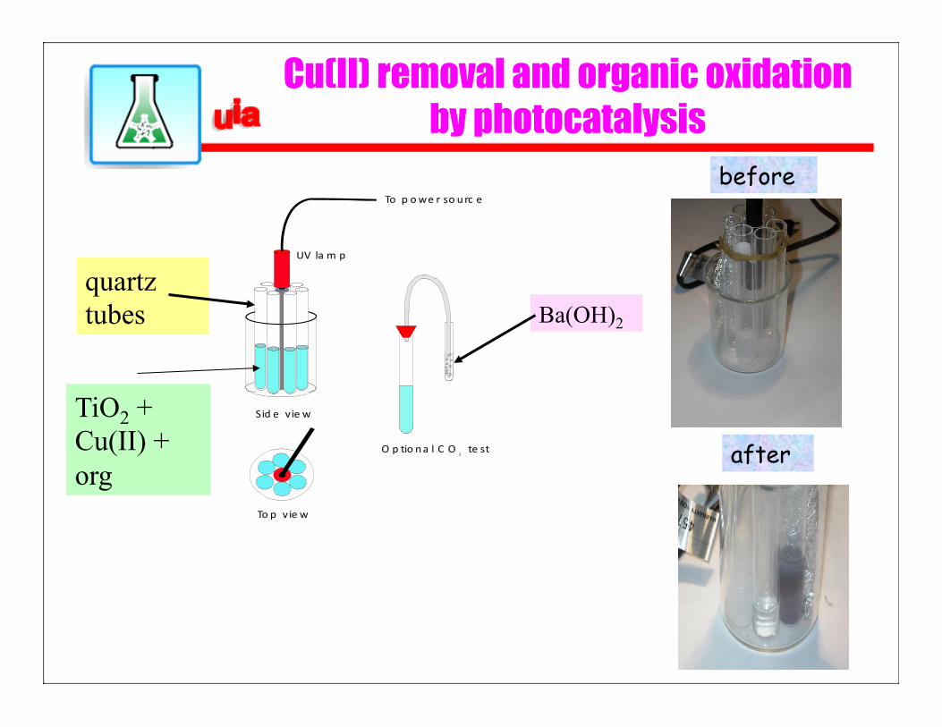
Cu(II) removal and organic oxidation by photocatalysis
To p v ie w
Sid e vie w
O p tio na l C O te st2
UV la m p
To p owe r so urc e
Ba(OH)2 quartz tubes
TiO2 + Cu(II) + org
before
after
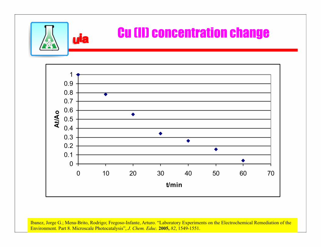
Cu (II) concentration change
00.10.20.30.40.50.60.70.80.91
0 10 20 30 40 50 60 70
t/min
At/Ao
Ibanez, Jorge G.; Mena-Brito, Rodrigo; Fregoso-Infante, Arturo. “Laboratory Experiments on the Electrochemical Remediation of the Environment. Part 8. Microscale Photocatalysis”, J. Chem. Educ. 2005, 82, 1549-1551.