Embed Size (px)
Citation preview

4
Pushing Out the Oil with Conformance Control
Daniel BorlingAmoco Production CompanyBairoil, Wyoming, USA
Ken ChanTulsa, Oklahoma, USA
Trevor HughesCambridge, England
Robert SydanskMarathon Oil CompanyLittleton, Colorado, USA
The growing problem of water production and a stricter environmental enforcement on water disposal are
forcing oil companies to reconsider conformance control—the manipulation of a reservoir’s external fluid
drive to push out more oil and less water. The technical challenges range from polymer chemistry to
detailed knowledge of reservoir behavior.
nTwo examples ofproduction reversalduring MarathonOil Company’s con-formance controlcampaign inWyoming’s Big Hornbasin. In each case,Marathon injected apolymer-gel systeminto an injector andnoted the produc-tion response inadjacent producers.Both examplesshow a dramaticreversal of bothdeclining oil rateand increasingwater/oil ratio(WOR)—see straight-line trends in topfigure. On average,each extra barrel ofoil derived fromtheir series of 29treatments costMarathon just $0.34.
Gel treatment
1000
10
1000
10
1000 100
Oil
rate
, BO
PD
Wat
er/o
il ra
tio (W
OR
)
Oil
rate
, BO
PD
r/oi
l rat
io (W
OR
)
Gel treatment
By late 1984, after several years’ research,Marathon Oil Company laboratories in Lit-tleton, Colorado, USA established a newpolymer-gel system to block high-perme-ability channels within a reservoir andimprove oil recovery. Previous attemptsusing less sophisticated chemistry had failedbecause the chemicals had become unsta-ble at reservoir conditions and also werepartially toxic. But now the chemistrylooked right. During the next three years,Marathon performed 29 treatments with thenew system in nine of its fields inWyoming’s Big Horn basin. Fourteen treat-ments were in carbonate formations, and 15were in sandstones.1
The greatest success occurred wheninjection wells were treated. The Big Hornreservoirs are known to be naturally frac-tured and the injected polymer-gel systemmost likely filled much of the fracture sys-tem between injector and neighboring pro-ducer. This would force subsequent water-
4 Oilfield Review
1984 1985 1986 1987 1988 1989
100 10
Wat
e
For help in preparation of this article, thanks to JimMorgan, BP Exploration, Sunbury-on-Thames, Eng-land; Paul Willhite, University of Kansas, Lawrence,Kansas, USA; Randy Seright, New Mexico Institute ofMining and Technology, Socorro, New Mexico, USA;Stephen Goodyear, AEA Petroleum Services, Dorch-ester, England; Kamel Bennaceur, Dowell, Caracas,Venezuela; Jon Elphick, Dowell, Montrouge, France;Françoise Callet, Schlumberger Cambridge Research,Cambridge, England.In this article, DGS is a mark of Dowell, FLOPERM isa mark of Pfizer Inc., and MARCIT and MARA-SEALare marks of Marathon Oil Company.

1. Sydansk RD and Moore PE: “Production Responses inWyoming’s Big Horn Basin Resulting From Applica-tion of Acrylamide-Polymer/Cr(III)-Carboxylate Gels,”paper SPE 21894, 1990, unsolicited.
2. Coleman B: “DTI’s IOR Strategy” in Best Practices forImproved Oil Recovery. London, England: IBC Tech-nical Services Ltd, 1993.
nThe UK Department of Trade and Industry’s estimate of improvedoil recovery (IOR) potential in the UK North Sea and the proportionexpected to be produced with conformance control.
46%
Not recoverable
11%
Improved oil recovery
Already produced23%
Remaining20%
Primary, secondary recoveryTechnique 106 Barrels of oil
Gas and additional oil recovery by late field depressurization 800
Viscous oil recovery processes 200Hot water SteamIn-situ combustionPolymer
Gas injection 1425
Modified waterflood 40Improved waterfloodSurfactantPolymerFoam flooding
Conformance control 500Polymer gelsMicrobial
Horizontal and extended- reach well technology 2400
drive to enter the matrix rock or fracturesuntouched by the treatment and push outoil. In many cases, a declining productionin the neighboring producer was dramati-cally reversed, staying that way for severalyears (previous page).
Overall, the 29 treatments yielded 3.7million barrels more oil than if the treat-ments had never been done, at a total costof just $0.34 per barrel. Considering theprice of oil at the time ranged from $30 to$24, Marathon had got themselves somevery inexpensive production and a clearsignal that the age of conformance controlhad begun.
What is Conformance Control? In the context of a reservoir produced withsome kind of external fluid drive, confor-mance describes the extent to which thedrive uniformly sweeps the hydrocarbontoward the producing wells. A perfectly con-forming drive provides a uniform sweepacross the entire reservoir; an imperfectlyconforming drive leaves unswept pockets ofhydrocarbon. Conformance control describesany technique that brings the drive closer tothe perfectly conforming condition—in otherwords, any technique that somehow encour-ages the drive mechanism to mobilize ratherthan avoid those hard-to-move pockets ofunswept oil and gas.
In the pantheon of techniques to improveoil recovery, conformance control is rela-tively unambitious, its goal being simply to
April 1994
improve macroscopic sweep efficiency.Most enhanced oil recovery (EOR) tech-niques, for example, also strive to improvemicroscopic displacement efficiency using avariety of surfactants and other chemicals toprize away hydrocarbon stuck to the rocksurface. Conformance control is also lessexpensive than most EOR techniquesbecause the treatments are better targetedand logistically far smaller.
Another factor also favors conformancecontrol. By redistributing a waterdrive so itsweeps the reservoir evenly, water cut isoften dramatically reduced. For manymature reservoirs, treatment and disposal ofproduced water dominate production costs,so less water is good. Environmental regula-tions also push oil companies to reducewater production. In the North Sea, residualoil in produced water dumped into theocean is restricted to 40 ppm, an upper limitincreasingly under pressure from the Euro-pean Community. In environmentally sensi-tive areas such as the Amazon rain forest,water disposal is also a major issue.
In a recent survey by the British Govern-ment Department of Trade and Industry(DTI) that reviewed the full spectrum ofimproved oil recovery (IOR) techniques andtheir potential for the UK North Sea, confor-mance control accounted for a possible fur-ther 500 million barrels of oil (above).2 Thisconstitutes 10% of the total IOR potential of
more than five billion barrels and con-tributes to raising final oil recovery from the43% obtained using primary and conven-tional secondary recovery methods to 54%,an increase of 11%. Unlike many of the IORtechniques reviewed by the DTI, confor-mance control technology was judgedmature enough to use immediately.
Conformance control during waterflood-ing covers any technique designed toreduce water production and redistributewaterdrive, either near the wellbore or deepin the reservoir. Near the wellbore, thesetechniques include unsophisticated expedi-ents such as setting a bridge plug to isolatepart of a well, dumping sand or cement in awell to shut off the bottom perforations, andcement squeezing to correct channeling andfill near-well fractures. Deep in the reservoir,water diversion needs chemical treatment.
Initially, straight injection of polymer wastried but proved uneconomical because ofthe large volumes required to alter reservoirbehavior and because polymers tend to getwashed out. The current trend is gels,which if correctly placed can do the job
45

Problem Solution
Oil
Oil
Gelling solution
Oil
Water
Gel fluid
Protective pressurefluid
Gelling solution
Shale
Oil
Water
Water
Oil
Oil
Cement
Shale
Oil
Water
Oil
Water
WaterGel
nMultiple causes of early water pro-duction during awaterdrive. Top: awatered-out zoneseparated from anoil zone by animpermeable shalebarrier—the solu-tion is to cement inbottom zone. Mid-dle: same as abovebut the shale bar-rier does not reachthe productionwell—cementingdoes not work, sothe solution is toinject gel into thelower zone whilebalancing theupper zone pressurewith inert fluid. Bottom: watered-outhigh-permeabilityzone sandwichedbetween two oilzones—the solutionis to isolate the zoneand inject gel.(Adapted from Mor-gan, reference 3.)
more efficiently with much smaller vol-umes. In the future, potentially less expen-sive foams including foamed gel may betried. Ultimately, reducing water productionmay require a new well. The choice oftechnique or combination of techniquesdepends crucially on the reservoir and itsproduction history.
Take, for example, the case of two pro-ducing zones separated by an impermeableshale, in which the bottom zone haswatered out (right). The first solution is tocement in the bottom zone. Suppose,though, that the shale barrier does notextend to the producing well. Then successwith the cement plug becomes short-livedand water soon starts coning toward the topinterval. The only recourse now is to injecta permeability blocker—some kind ofgelling system—deep into the lower zone.The trick is not letting the gelling systeminvade the upper zone. This can beachieved by pumping through coiled tubingto the top of the watered-out zone whilesimultaneously pumping an inert fluid,water or diesel fuel through the annulus intothe upper zone to prevent upward migrationof the gelling system.
Deep gelling systems are also the answerfor a high-permeability but watered-out for-mation sandwiched between two lower per-meability formations—the classic break-through scenario. A casing patch or cementsqueeze may halt water production momen-tarily, but long-term shutoff requires adeeper block. The fractured reservoir is avariant of this scenario. If natural fracturesare interconnected, they can provide aready conduit for water breakthrough, leav-ing oil in the matrix trapped and unpro-ducible. The solution is to inject and fill thefractures with a gelling system, that oncegelled, forces injection water into the matrixto drive the oil out.
The possibilities are endless, and there areas many solutions to blocking water produc-tion as there are reservoirs to block.3 Thechallenges for the reservoir engineer con-templating conformance control are know-ing why, where and how water is produced,and which water blocking technique to use.In the case of using a gelling system, thereare the additional challenges of being sure
46
that the chemistry is robust enough to gowhere it is intended, deep in the reservoir,and that it is formulated correctly to actuallygel. The combination of these challenges isdaunting and explains conformance con-trol’s checkered history. If the technique ismore widely accepted today, it is onlybecause these challenges are now recog-nized, not because they are resolved.
We’ll next look at the chemistry of gellingsystems, the predominant method of block-ing permeability and redistributing water-drive, and then illustrate the care successfulproponents of the technique must exercisein choosing and implementing treatments.
Gelling System ChemistryPhillips pioneered the first polymer gels forconformance control in the 1970s. Sincethen, research into gelling systems has beenmaintained at an intense level.4 Polymer gelsystems start as a flowing mixture of twocomponents—high-molecular weight poly-mer and another chemical called a cross-linker. At some trigger, each cross-linkingmolecule, tiny compared with the polymermolecule, starts attaching itself to twopolymer molecules chemically linking themtogether (next page, left). The result is a three-dimensional tangle of interconnected poly-mer molecules that ceases behaving like afluid and can eventually constitute a rigid,immobile gel.
The trick in designing these systems isfinding chemicals that are insensitive to the
Oilfield Review

April 1994
nGel formation as cross-linking molecules(red) connect polymer molecules (purple).
3. Morgan J: ”State-of-the-Art of Water Shut-off Well Treat-ments“ in Best Practices for Improved Oil Recovery.London, England: IBC Technical Services Ltd, 1993.Seright RS and Liang J: “A Survey of Field Applicationsof Gel Treatments for Water Shutoff,” paper SPE 26991, presented at the 1994 SPE Permian Basin Oil & Gas Recovery Conference, Midland, Texas, USA,March 16-18, 1994.
4. Needham RB, Threlkeld CB and Gall JW: “Control of Water Mobility Using Polymers and MultivalentCations,” paper SPE 4747, presented at the SPEImproved Oil Recovery Symposium, Tulsa, Oklahoma,USA, April 22-24, 1974.
5. For a general review:Sorbie KS: Polymer-Improved Oil Recovery. Glasgow,Scotland: Blackie, 1992.Woods CL: Review of Polymers and Gels for IOR Applications in the North Sea. London, England: HMSO Publications Centre, 1991.
Pre-gel
Cross-linking Begins
Gel Formed
widely varying conditions of the subsurface,such as temperature, the ionic compositionof the connate water, its pH, the presence ofeither carbon dioxide [CO2] or hydrogensulfide [H2S], and the absorptivity of therock grains, to name a few. The polymermay be naturally occurring or manufacturedsynthetically. The cross-linker may be metalions or metallic complexes that bond ioni-cally to the polymer, or organic moleculesthat bond covalently.
There have been innumerable systemsdeveloped since the 1970s, too many todescribe, so we will concentrate on the evo-lution of a particularly promising system thatuses the synthetic polymer called polyacry-lamide (PA).5 This readily available polymercomprises a carbon-carbon backbone hungwith amide groups, possibly tens of thou-sands of them to provide molecular weightsin the millions (below). In its pure state, thepolymer is electrically neutral, seeming topreclude any cross-linking through ionicbonding. However, when mixed with a littlealkaline solution, such as sodium hydroxide,or when subjected to elevated temperature,some of the amide groups convert to car-boxylate groups. Each of these carries a neg-ative charge. The proportion of amidegroups that convert to carboxylate is calledthe degree of hydrolysis (DH) and typicallyvaries from 0 to 60%. In this form, the poly-
Partially Hydrolyzed Polyacrylamide (PHPA)
Amide Carboxylate Am
Amide Monomer
C
ONH2
Polyacrylam
C
H
C
H
. . . .
C H
. . . . C CC C C
H H
HH H
ONH2 O NH2O–
Na+
NH2 O
H
C C C
C
H
C
H
H
mer is called partially hydrolyzed polyacry-lamide (PHPA) and with its negativelycharged carboxylate groups becomes sus-ceptible to ionic cross-linking.
Efficient cross-linkers are trivalent metalions such as aluminum, Al3+, and chromium,Cr3+. These can be packaged either as sim-ple inorganic ions in solution or within solu-ble chemical complexes in which the triva-lent ion is associated with small inorganic ororganic groups called ligands. Some of thefirst polymer-gel systems from the early1970s used aluminum in the form of alu-minum sulfate. Whatever the choice, thetrivalent metal ion readily links carboxylate
47
nChemical struc-tures of the amidemonomer, poly-acrylamide poly-mer (PA) and par-tially hydrolyzedpolyacrylamidepolymer (PHPA)with its negativelycharged carboxy-late groups.
ide
ide (PA)
C C
H
HC
C
H
H H
O
. . . .
NH2 O
H

groups on different polymer molecules, orpossibly on the same molecule (above). Rel-atively few cross links are needed to ensurethat the polymer-cross-linker mixture gels.
The chemical environment deep in an oilreservoir, however, often conspires to wreckthis idealized picture. In the case of alu-minum sulfate, cross-linking is very muchpH dependent. While the mixture remainsacidic, no gel forms so the treatment fluidscan be safely injected into the reservoir. Butwhen the fluids hit the reservoir, pH risesrapidly and gelling occurs immediately. The
system therefore worked only very near thewellbore and suffered from total lack ofcontrol—gelling time was entirely at themercy of the reservoir environment.
Toward the 1980s, Cr3+ rather than Al3+
was tried as the cross-linker, not because itprovided better cross-linking, but because itpromised better gelation control. The tech-nique to achieve this, though, was not touse Cr3+ directly but rather Cr6+. This ion isinert with respect to cross-linking but can bereduced to Cr3+ using a variety of reducingagents that could be injected with the treat-ment fluids. In theory, this would allow thesystem to be injected deep into the forma-tion before gelling.
In practice, however, there were threeproblems. It was difficult to provide suffi-ciently long gelation times at high tempera-ture; the whole system was sensitive toH2S—itself a reducing agent; and, worst,Cr6+ was recognized as toxic and even car-cinogenic. These problems appeared to beresolved in the mid 1980s when an environ-mentally friendly, controllable chromiumsystem was developed at the MarathonPetroleum Technology Center in Littleton,Colorado, USA.6
Scientists there had the idea of packagingCr3+ as the metal-carboxylate complex,chromium acetate. The acetate group has astructure very similar to the carboxylategroups on PHPA polymer (right). Thus, theCr3+ ion is attracted to both the acetate lig-and within the complex and the carboxylategroups on the PHPA polymer. This slows the
High pH
Low pH
Chromium acetate
Cr
O–
. . . .
H
C
O
C CC PHPA. . . .
O– O
C
H
C
CC . . . . PHPA
H2O
H2O
Chromium acetateO
H2O
AcAc
Ac
Ac
AcAc
CrCr
Ac Ac
OH Ac
Cr OH Cr OH Cr
H2O
Ac H2O
Ac
C
H
C
O– O
CC . . . . PHPA
. . . . C
H
C
O
C C
O–
. . . .
Ac is C
H
C
H
O– O
H
. . . .
. . . .
PHPA
Cross-linkerH2O H2OM
O–
C
H H
C
. . . .
NH2 O
. . . . PHPA
O
C
C
C
H
H
C
H
H
. . . . . . . . PHPAC
H
H
C
H
C
O– O
C
H
H
C
H
C
NH2O
nMarathon’s MARCIT gel in three final states depending on concentration, from left:tonguing gel, intermediate strength gel and rigid gel. (Courtesy of Marathon Oil Company.)
nChemical linking of partially hydrolyzedpolyacrylamide polymer (PHPA) moleculeswith trivalent metal ions, indicated generi-cally as M 3+.
nChemical structure of chromium acetatecomplexes as a function of pH and itslinking with PHPA. (Adapted from Tackett JE:“Characterization of Chromium (III) Acetate inAqueous Solution,” Applied Spectroscopy 43(1989): 490-499.)
48 Oilfield Review
Tonguing Intermediate Rigid

cross-linking process and ultimately givesthe chemist effective control over gel time.
Substantial laboratory testing showed thatthe behavior of the PHPA-chromium acetatesystem was insensitive to pH from about 2to 12.5, relatively insensitive to ions in for-mation fluids, and untroubled also by H2Sand CO2. Furthermore, it could be formu-lated to give a wide range of gel strengthsand gel times at temperatures up to 124°C[255°F] and even higher. Marathon nowlicenses this system in two forms. ItsMARCIT system using PHPA polymer with amolecular weight of more than five millionis designed for filling and blocking fractures,as used for example in the Wyoming trials(previous page, bottom left). Its MARA-SEALsystem using PHPA with a low molecularweight in the mere hundreds of thousandsand lower DH has reduced pre-gel viscosityand is designed for filling and blockingmatrix reservoir rock.
The chemistry and physics of polymer gelsare complex and often controversial. Onepoint of dispute is whether polymers such asPHPA, even with relatively low molecularweights, as in MARA-SEAL, can be success-fully injected through narrow pore throatsinto reservoir matrix rock. Marathon’s labo-ratory tests suggest they can, although reser-voir conditions may not have been dupli-cated exactly. Others believe that because ofthe interaction of the polymer with the porewalls and the very size of the polymermolecule, the systems have difficulty negoti-ating small pore spaces, limiting injection.The need for matrix-filling gel systems,though, is not in dispute.
BP Exploration and ARCO are currentlytesting a system comprising PHPA and analuminum-based cross-linker that is hopedwill reach deep in the matrix reservoir of theKuparuk field in Northern Alaska. The cross-linker is another metal-carboxylate com-plex, aluminum citrate. But unlikechromium acetate, this links the PHPA intwo distinct temperature-controlled stages(right ).7 In the first stage which occursrapidly in cold water, each aluminum citrate
nTwo-stage cross-linking using PHPA and aluminumcitrate, being used by BP Exploration and ARCO in theKuparuk field, Alaska.
6. Sydansk RD: “A New Conformance-Improvement-Treatment Chromium (III) Gel Technology,” paperSPE/DOE 17329, presented at the SPE/DOE EnhancedOil Recovery Symposium, Tulsa, Oklahoma, USA,April 17-20, 1988.
7. Fletcher AJP, Flew S, Forsdyke IN, Morgan JC, RogersC and Suttles D: “Deep Diverting Gels for Very Cost-Effective Waterflood Control,” Journal of PetroleumScience and Engineering 7 (1992): 33-43.Rogers C, Morgan JC and Forsdyke IN: “Deep Divert-ing Gels for Improved Profile Control,” in Oil and GasTechnology in a Wider Europe: Proceedings of the 4thEC Symposium, Berlin, Germany, November 3-5,1992. Aberdeen, Scotland: Petroleum Science andTechnology Institute (1992): 381-399.
O
C
O CH2 O
O C CAl
CH2O
C
O
Aluminum citrate
C
H
C
H
C
H
C
H
HH
. . . .
Stage 1 : Rapid at Low Temperature
C
O
C
NH2 O
CH2O
O C CAl
C
O
OH
O
CH2 CO2 –
Na+
. . . . PHPA
Pre-gel
H H HH
HH
Na+
C
O–O
C
NH2 O
. . . . C C CC . . . . PHPA
C
H
C
H
C
H
C
H
C C HH
. . . .
NH2 O OO
Stage 2 : Rapid at High Temperature
O C CAl
OH
O
CH2 CO2 – Na+
Na+
. . . . PHPA
O
C C CC
H H HH
C C HH
NH2 O OO
. . . . . . . . PHPA
OH
CH2 CO2 –
49April 1994

molecule bonds to just one polymer car-boxylate site. In the second stage, whichoccurs only above 50°C [122°F], the alu-minum citrate complex can attach to a sec-ond carboxylate group thereby cross-linkingtwo polymer molecules and contributing toproduce a gel network. Because the cross-link itself contains carboxylate groups andthese have an affinity for water molecules,the formed gel may flow in a beaker, yetprovide an adequate permeability block inporous rock.
BP and ARCO’s strategy is to pump thesystem into the reservoir through injectionwells, where the cooler temperature of theinjection water will promote only the first-stage reaction, resulting in a pumpable fluidof low viscosity. Then, as the fluid perme-ates deep into high-permeability sections ofthe reservoir and experiences higher tem-peratures, the second-stage will kick in andenough of a gel will form to divert water-drive to less permeable zones. In prepara-tion for field tests, BP conducted an exten-sive computer simulation of the temperaturedistribution and likely flow patterns of thepolymer-gel system within the reservoir, andalso laboratory studies of the systeminjectability through 190-ft [58-m] longslimtubes packed with sand (below). It istoo early to tell whether their ambitiousplan is working in the field.
The problem of injecting polymer gel sys-tems through the narrow pore spaces ofmatrix is multifaceted and has been a focus
of a three-year Department of Energy projectat the New Mexico Institute of Mining andTechnology in Socorro, New Mexico, USA.8At the pore scale, there are three mainissues. First, some of both the polymer andcross-linker will get adsorbed onto the porewalls during injection. In itself, fluid reten-tion is not a problem as long as most of thetreatment fluid reaches its destination deepin the reservoir. More serious is if the absorp-tivity rates of the two components are differ-ent. Then, the volumetric ratio of polymer tocross-linker will change as the treatmentinvades the formation, possibly compromis-ing control of gelling time. BP’s aluminumcitrate system may overcome this hazardbecause the cross-linker makes its first
attachment to the polymer before injection,rendering the two components inseparable.
The second issue is polymer elasticity.Polymers being long, complex moleculesexhibit a degree of elasticity that makes howthey move somewhat dependent on theirsurroundings. For example, the viscosityobserved in a free polymer solution will notnecessarily be mirrored when the samepolymer is trying to squeeze through a porethroat (left ). In general, polymer elasticityinhibits the progress of treatment fluidthrough porous medium. Third, there is thequestion of pore throats actually becomingblocked by microclusters containing severalpolymer molecules—these may developprior to bulk gelling.9 All three issues arebeing researched and to an extent representthe key to leaping from laboratory evidenceto certainty on what happens in the field.
Inorganic Gelling SystemsAn alternative gelling system that guaranteesinjectability into matrix rock uses simpleinorganic chemicals that have flowing prop-erties nearly identical to those of water.Inorganic gels were discovered in the 1920sand are used to this day for plugging lost cir-culation, zone squeezing and consolidatingweak formations. Their failing for confor-mance control has been a very rapid gela-tion time, but recent innovations using alu-minum rather than silicon have resolved thisproblem. An example is the DGS DelayedGelation System developed by the Schlum-berger pumping company, Dowell.10
The DGS system comprises partiallyhydrolyzed aluminum chloride that precipi-tates to a gel when an activator responds totemperature and raises the system pH abovea certain value (next page). A gel material-izes because aluminum and hydroxyl ionslink with each other in such a way as toform an amorphous, irregular three-dimen-sional impermeable network. The DGS sys-tem is quite insensitive to the subsurfaceenvironment, except for the caution thatdivalent anions in the formation water, suchas sulfates and carbonates, SO4
2– and CO32–,
can enter the system and affect the gel struc-ture. Conformance control with the DGSsystem has been tried with success fromAustralia to South America (see “Profile
50 Oilfield Review
Pore throat
Pore
Res
ista
nce
fact
or
200
180
160
140
120
100
80
40
20
0
60
Cold 30-ft sections Warm 2.5-ft section
Hot 10-ft sections
42 days
40 days
37 days
Gelling system movement
nSchematic of polymer molecule elongat-ing within pore throat. As the moleculeelongates, its effective hydrodynamic vol-ume and therefore also its viscosityincrease, impeding injection.
nResistance factors to PHPA-aluminum citrate injection,measured along a 190-ft slimtube packed with sand, inexperiments by BP Exploration. The gelling systemremains fluid in cold and warm sections of the slimtube;it fully gelled only some way into the hot section, once itarrived there 37 days after injection began. (Adapted fromFletcher et al., reference 7.)

Modification Using DGS Gelling System,”next page).
Besides their inherent ability to deeplypermeate matrix rock, inorganic gels haveanother advantage over their polymer-basedcousins. If the treatment fluid gets incor-rectly placed causing a deterioration inreservoir performance, inorganic gel can beremoved with acid. Of course, the acid hasto be able to reach the gel to be able toremove it. Polymer gels, on the other hand,cannot be dismantled easily and are there-fore usually in place for the duration.
If deep penetration in matrix is one keyfactor in the conformance control debate,another concern is contamination of thegelling system through contact with ions inthe formation water. As noted, the DGS sys-tem may be adversely affected by divalentanions. PHPA, on the other hand, bothbefore and after gelling may be affected by
divalent cations such as Ca2+, which are rel-atively ubiquitous in formation waters. Ca2+
ions associate with the carboxylate groupsin PHPA causing free polymer to precipitate.This becomes more of a problem as thedegree of hydrolysis of the polymerincreases, and DH can increase withincreasing temperature. Research initiated atPhillips Petroleum Co. and pursued furtherat Eniricerche SpA, Italy’s national researchcenter for the oil industry situated nearMilan, has identified other polymer typesthat may offer better protection from ionicattack yet still be susceptible to ionic cross-
8. Seright RS and Martin FD: Fluid Diversion andSweep Improvement with Chemical Gels in OilRecovery Processes, Annual Report for the PeriodMay 1, 1989 - April 30, 1990. Bartlesville, Okla-homa, USA: U.S. Department of Energy, 1991:DOE/BC/14447-8.Seright RS and Martin FD: Fluid Diversion andSweep Improvement with Chemical Gels in OilRecovery Processes, Second Annual Report for thePeriod May 1, 1990 - April 30, 1991. Bartlesville,Oklahoma, USA: U.S. Department of Energy, 1991:DOE/BC/14447-10.Seright RS and Martin FD: Fluid Diversion andSweep Improvement with Chemical Gels in OilRecovery Processes, Final Report and Third AnnualReport for the Period May 1, 1991 - April 30, 1992.Bartlesville, Oklahoma, USA: U.S. Department ofEnergy, 1992: DOE/BC/14447-15.
9. Todd BJ, Willhite GP and Green DW: “A Mathemati-cal Model of In-Situ Gelation of Polacrylamide by aRedox Process,” SPE Reservoir Engineering 8 (Febru-ary 1993): 51-58.
10. Chan KS: “Reservoir Water Control Treatments Usinga Non-Polymer Gelling System,” paper OSEA88134, presented at the 7th Offshore South East AsiaConference, Singapore, February 2-5, 1988.
51April 1994
nDevelopment of Dowell DGS gel as the system pH increases, with postulated gel structure showing aluminumatoms in blue and oxygen atoms in red. Hydrogen will be loosely associated with the exterior, singly bondedoxygen atoms.
pH
Time, hr
Vis
cosi
ty, c
p
0 4 8 12 160
20
40
80
4.0
4.5
5.0
6.0
5.5

Venezuela
In Venezuela, oil company Corpoven, S.A. has
been evaluating several gelling systems at its
national research center INTEVEP. Laboratory
analysis narrowed its choice to the inorganic DGS
system of Dowell and Pfizer Inc.’s FLOPERM sys-
tem. The FLOPERM system uses a monomer
called melamine—a monomer comprises a sin-
gle chemical group from which polymer is
built—and an organic covalent-bonding cross-
linker, in this case formaldehyde, to form poly-
mer gels in situ.1 In the field, Corpoven tried the
DGS system in two wells, the FLOPERM system
in one well, and both systems in a fourth well
with each system restricted to a different produc-
ing zone.
The most successful treatment was in one of
the two wells receiving the DGS system only. The
treatment was designed to block water coning at
the bottom of an oil producer in a zone 6 ft [2 m]
thick. The reservoir was an 80-md limestone at
9145 ft [2787 m]. Downhole static temperature
was 140°C [284°F], high for most commercially
available gelling systems.
During a period of 10 hours, 300 barrels of
DGS treatment fluid were pumped through tubing
and packer into the watered-out zone at 0.5
bbl/min. Simultaneously, diesel fuel was pumped
down the annulus above the packer into the over-
lying oil zone to prevent the treatment fluid from
entering the oil zone. The treatment fluid was
then displaced with 78 barrels of water and
allowed to gel for a week.
When the well was put back on production, oil
production increased more than 2.5 times and
water cut had dropped 25%. Eleven months later,
36,000 additional barrels of oil had been pro-
duced and water cut was still 15% less than
before the treatment.
Profile Modification Using DGS Gelling System
Gilberto TorresCorpoven, S.A.Caracas, Venezuela
nInjection profiles in wells K13 and K35 before andafter pumping DGS gelling system into the lower fivelayers. Conformance is not perfect after the treat-ment, but at least the lower layers are now takingsome of the injected water. (Courtesy of WAPET.)
1. Chang PW, Goldman IM and Stingley KJ: “LaboratoryStudies and Field Evaluation of a New Gelant for High-Temperature Profile Modification,” paper SPE 14235, pre-sented at the 60th SPE Annual Technical Conference andExhibition, Las Vegas, Nevada, USA, September 22-25,1985.
Mourhaf JabriCanning Vale, Western Australia
Carlos MogollonEl Tigre, Venezuela
The following two conformance control case studies describe a producer that is watered-out from coning (Venezuela) and water
injectors that have poor injection profiles (Australia).
Australia
In the Barrow Island field in Western Australia,
Western Australian Petroleum (WAPET) has been
deploying DGS treatments in injector wells to
redistribute waterdrive to low-permeability parts
of their multilayered, predominantly nonfissured
reservoir. In two injection wells, K35 and K13,
the top three of a total of nine reservoir sand lay-
ers were taking almost all the injection
water—about 100 BWPD. The bottom six layers
were getting practically nothing.
In a treatment design that was similar for both
wells, WAPET placed a plug below the third layer
and injected about 400 barrels of DGS system
over three to four days, anticipating that the
treatment fluid would invade at least 20 ft [6 m]
into the reservoir matrix. After allowing the gel
enough time to set, they then reperforated the
lower zones and began reinjecting water. As
might be expected, injection rates were less than
before—74 versus 150 BWPD in K13 and 105 ver-
sus 120 BWPD in K35—due to the plugging
action of the gel. But the injection was better
distributed, as shown by tracer surveys (left). The
top layers still take their fair share, but now the
bottom layers also take some water. Correspond-
ingly, water cut in adjacent producers dropped by
more than 50%.
52 Oilfield Review
Pro
duct
ion
laye
rs
Injection Profiles
9
8
7
6
5
4
3
2
1
K13
Flow into each layer, %0 20 40 60 80 100
9
8
7
6
5
4
3
2
1K35
Pro
duct
ion
laye
rs
Pre-treatment
Post-treatment

11. Doe PH, Moradi-Araghi A, Shaw JE and Stahl GA:“Development and Evaluation of EOR PolymersSuitable for Hostile Environments: Copolymers ofVinylpyrrolidone and Acrylamide,” paper SPE14233, presented at the 60th SPE Annual TechnicalConference and Exhibition, Las Vegas, Nevada,USA, September 22-25,1985.Moradi-Araghi A, Cleveland DH and Westerman IJ:“Development and Evaluation of EOR PolymersSuitable for Hostile Environments: II—Copolymersof Acrylamide and Sodium AMPS,” paper SPE16273, presented at the SPE International Sympo-sium on Oilfield Chemistry, San Antonio, Texas,USA, February 4-6, 1987.Albonico P and Lockhart TP: “Divalent Ion-ResistantPolymer Gels for High-Temperature Applications:Syneresis Inhibiting Additives,” paper SPE 25220,presented at the SPE International Symposium on
nAn example of a polymer that may be more resistant to diva-lent cation attack than PHPA. Called poly/vinylpyrrolidone-acry-lamide, this polymer gains stability from the inert pyrrolidonegroups that substitute for the regular amide or carboxylategroups usually found on PHPA.
. . . . C
H
C
C
OO–
C
H
NH2
C
C
O
C. . . . C
N
C
C C
HHC
H
HHHHHH
CarboxylateAmideVinylpyrrolidone
H
H H
O
linking.11 One solution is to use syntheticpolymers in which some amide groups arereplaced by a more inert chemistry that can-not hydrolyze to carboxylate and thereforeremain vulnerable to wandering divalentcations (right).
Part of the Eniricerche effort is directedtoward improving the temperature rating ofpolymer gel systems. Chemical processalways speeds up with elevated tempera-ture, and this makes gelling increasingly dif-ficult to control. The most interesting resultto date in improving gelation control at hightemperature is through use of chromiummalonate, yet another metal-carboxylatecomplex, as cross-linker.12 Malonate, whichhas two carboxylic groups as opposed to thesingle group in acetate or citrate, appears toextend gelation time by an order of magni-tude (below). As a bonus, surplus malonateuncomplexed with chromium seems toretard gelation even more and also scav-enges those divalent cations such as Ca2+
that can precipitate the PHPA polymer.A final challenge in designing polymer
gels is ensuring long-term stability. Most gelsrun the risk of dehydration, a process calledsyneresis that causes shrinkage and loss ofconformance. But it remains an open ques-tion how serious this shrinkage can be, andwhich gelling system, if any, is leastaffected. As with many other aspects ofgelling systems, syneresis remains an activefield of research.
Oilfield Chemistry, New Orleans, Louisiana, USA,March 2-5, 1993.
12. Lockhart TP and Albonico P: “A New Gelation Tech-nology for In-Depth Placement of Cr+3/PolymerGels in High-Temperature Reservoirs,” paper SPE24194, presented at the SPE/DOE Eighth Symposiumon Enhanced Oil Recovery, Tulsa, Oklahoma, USA,April 22-24, 1992.
13. Seright RS: “Placement of Gels to Modify InjectionProfiles,” paper SPE/DOE 17332, presented at theSPE/DOE Enhanced Oil Recovery Symposium,Tulsa, Oklahoma, USA, April 17-20, 1988.
April 1994
nMalonate, suggested as a stable com-plex with chromium for cross-linking, also acts as a calcium divalent cationscavenger.
C
C
O–
O
. . . .
C O–
. . . .
Ca2+ Malonate
O
H H
Treatment Fluid PlacementAfter chemistry, the second major hurdle inconformance control is placement of treat-ment fluid. This shifts attention from thechemist to the reservoir engineer who mustask and be able to answer some tough ques-tions: Given a reasonably functional poly-mer-gel system, what factors determinewhether a reservoir will benefit from treat-ment? And if a reservoir seems a good can-didate, how should the treatment proceed?Via producers or injectors? And using somekind of zone isolation or none? Candidateselection is how the reservoir engineer’schallenge is paraphrased.
The three-year Department of Energy pro-ject at the New Mexico Institute of Miningand Technology has directed attention tomost of these questions, and some guide-lines have emerged.8 For example, if thetreatment fluid is pumped into injectionwells—which according to numerous casestudies seem to give better results than pro-ducers—theoretical studies show that zoneisolation is mandatory when attempting toinject gel into matrix rock porosity but notimportant when filling fracture porosity.13
This is because if a matrix reservoir is filledwith gel in the wrong places, there is liter-ally no conduit remaining for production.However, in a fractured reservoir where gelfills the fractures, the matrix rock stillremains for producing oil.
Ultimately, computer simulation can beinvoked to test whether a proposed treat-ment is likely to work. But this requiresmore than simulation of reservoir fluid flow.Also needed is a chemical simulator thatmodels how the gelling system reacts with
53

the reservoir environment and how gellingconstituents react with each other. Asreported earlier, BP Exploration performedsuch a computer simulation in its planningfor treating the Kuparuk field with a PHPA-aluminum citrate system. Another fluid-flow/chemical simulator, called SCORPIO,is offered by AEA Petroleum Services, whichis based in Dorchester, England.14 This sim-ulator is currently being used to investigatethe feasibility of polymer-gel conformancecontrol in several North Sea fields.15
The prudent operator, of course, will tem-per sophisticated modeling with a gooddose of common sense. In addition, it doesnot hurt to have enough injection and pro-duction data available to fully comprehendhow the reservoir will react if prodded. Sur-prisingly, reservoir production data can besparse and poorly documented. Frequently,production data are known for groups ofwells tied to a common pipeline and not forindividual wells. However, this was not thecase in the Wertz field in Wyoming, USA forwhich Amoco Production Co. began con-templating a series of conformance controltreatments in mid-1991 (below).16
54
nStructure of Amoco’s Wertz field amance control treatments performetional barrels of oil production via and #127. A treatment in well #120of oil production via neighboring p
Case StudyThe Wertz field was a model implementa-tion of a CO2 tertiary flood, and, as a result,field performance had been copiously docu-mented. Not only were individual producersand injectors monitored daily, but flow ratesof the three phases present—oil, water andCO2—were also measured. These measure-ments were made in special substations,one substation for every dozen wells or so,each with elaborate and automatic appara-tuses for sampling each well’s flow in or outand the flow’s breakdown into three phases.
The Wertz producing formation is a 470-ft[143-m] thick aeolian sandstone at an aver-age depth of 6200 ft [1890 m], with 240 ft[73 m] of net pay having 10% porosity and13-md permeability. The formation isbelieved to have some fractures and is oilwet. Sixty-five wells over 1600 acres areused for production and many more thanthat have been drilled for injection—alter-nating water and CO2 injection, commonlyreferred to as water-alternating-gas (WAG)injection. By mid-1991, the field’s fate liter-ally hung in the balance. The field’s totalproduction had dropped precipitously to
#127#125
#84
#142
#120
t Bairoil, Wyoming, USA. Confor-d in well #84 gained 110,000 addi-
neighboring producing wells #125 gained 140,000 additional barrelsroducing well #142.
4000 BOPD from 12,000 BOPD in 1988, asteeper than expected decline during ter-tiary flooding.
After trying several other techniques tohalt the decline, Amoco turned to confor-mance control, eventually completing 12treatments using Marathon’s polymer geltechnology. Ten treatments were in injectorsand two in producers. Some treatmentswere aimed at blocking matrix porosity andsome aimed to place gel in reservoir frac-tures. We’ll highlight one example of each,illustrating with injector treatments sincethese were the more successful. In somecases, the treatments extended the life of apattern by two years. Overall, Amoco esti-mates that for a total cost of $936,000, thetreatments have yielded an increase in pro-ducible reserves of 735,000 barrels—that is$1.27 per barrel.
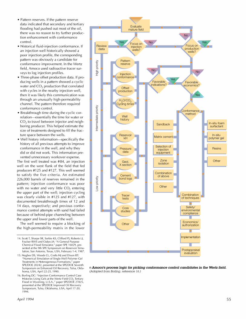
A crucial preliminary step in all thesetreatments was candidate selection—thecompilation and review of data to deter-mine a well’s suitability for treatment (nextpage). Although any field information couldbe relevant, five data types were deemedparticularly important. They were:
Oilfield Review
Yes
No
Evaluatemature field
Focus oninjection wells?
Low
prio
rity
Inte
rmed
iate
prio
rity
Hig
h pr
iorit
y
Reviewdata
Well history
H2O/CO2Cycling times
Offsetproduction
Injection conformance
Pattern reserve
Cement bond logs
Geol. X section
Pressuredata
Reservoir kH
Favorableindications?
Other
Core studies
Tracertests
Favorableeconomics?
Focus onproduction
wells?
Yes
No
No
Yes
Safety/environmentalcompliance
Economics/authorization
Combination of techniques
Conformancemethod
In-situ foamsurfactant
In-situpolymer gel
Resins
Other
Sandback
Matrix cement
Zoneisolation
Combination of above
Other
NoYes
Selection ofinjection
equipment
• Pattern reserves. If the pattern reservedata indicated that secondary and tertiaryflooding had pushed out most of the oil,there was no reason to try further produc-tion enhancement with conformancecontrol.
• Historical fluid-injection conformance. Ifan injection well historically showed apoor injection profile, the correspondingpattern was obviously a candidate forconformance improvement. In the Wertzfield, Amoco used radioactive tracer sur-veys to log injection profiles.
• Three-phase offset production data. If pro-ducing wells in a pattern showed a cyclicwater and CO2 production that correlatedwith cycles in the nearby injection well,then it was likely this communication wasthrough an unusually high-permeabilitychannel. The pattern therefore requiredconformance control.
• Breakthrough time during the cyclic cor-relation—essentially the time for water orCO2 to travel between injector and neigh-boring producer. This helped estimate thesize of treatments designed to fill the frac-ture space between the wells.
• Well history information—specifically thehistory of all previous attempts to improveconformance in the well, and why theydid or did not work. This information pre-vented unnecessary workover expense.
The first well treated was #84, an injectionwell on the west flank of the field that fedproducers #125 and #127. This well seemedto satisfy the five criteria. An estimated226,000 barrels of reserves remained in thepattern; injection conformance was poorwith no water and very little CO2 enteringthe upper part of the well; injection cyclingwas clearly visible in #125 and #127, withdocumented breakthrough times of 12 and14 days, respectively; and previous confor-mance control attempts with sand had failedbecause of behind-pipe channeling betweenthe upper and lower parts of the well.
The well seemed to require a blocking ofthe high-permeability matrix in the lower
55April 1994
nAmoco’s process logic for picking conformance control candidates in the Wertz field.(Adapted from Borling, reference 16.)
14. Scott T, Sharpe SR, Sorbie KS, Clifford PJ, Roberts LJ,Foulser RWS and Oakes JA: “A General PurposeChemical Flood Simulator,” paper SPE 16029, pre-sented at the 9th SPE Symposium on Reservoir Simu-lation, San Antonio, Texas, USA, February 1-4, 1987.
15. Hughes DS, Woods CL, Crofts HJ and Dixon RT:“Numerical Simulation of Single-Well Polymer GelTreatments in Heterogeneous Formations,” paperSPE/DOE 20242, presented at the SPE/DOE SeventhSymposium on Enhanced Oil Recovery, Tulsa, Okla-homa, USA, April 22-25, 1990.
16. Borling DC: “Injection Conformance Control CaseHistories Using Gels at the Wertz Field CO2 TertiaryFlood in Wyoming, U.S.A.,” paper SPE/DOE 27825,presented at the SPE/DOE Improved Oil RecoverySymposium, Tulsa, Oklahoma, USA, April 17-20,1994.
Postappraisal evaluation
Implementation

56 Oilfield Review
nInjection profilesfor water and CO2in well #84 beforeand at varioustimes after the geltreatment, whichwas confined to thehigh-permeabilityzone at the bottomof the well. Thetreatment dramati-cally improvedinjection confor-mance. (Courtesy ofAmoco Production Co.)
San
d
Dep
th, f
t
San
d
Zone of suspected high permeability
Water
CO2
1 month pre-treatment 3 months post-treatment 10 months post-treatment 12 months post-treatment
6400
6500
6600
1 month pre-treatment 1 month post-treatment 7 months post-treatment 12 months post-treatment
6400
6500
6600
Zone of suspected high permeability
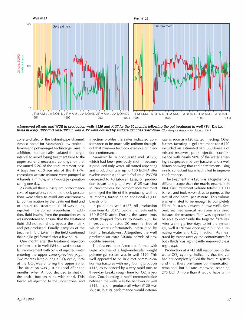
nImproved oil rate and WOR in production wells #125 and #127 for the 30 months following the gel treatment in well #84. The hia-tuses in early 1992 and mid-1993 in well #127 were caused by surface facilities downtime. (Courtesy of Amoco Production Co.)
Oil
rate
, BO
PD
Wat
er/o
il ra
tioWell #127 Well #125
1000
100
10
J F M A M J J A S O N D J F M A M J J A S O N D 1991 1992
J F M A M J J A S O N D 1993 1994
J F M A M J J A S O N D J F M A M J J A S O N D 1991 1992
J F M A M J J A S O N D 1993 1994
J J
Gel treatmentGel treatment
zone and also of the behind-pipe channel.Amoco opted for Marathon’s low molecu-lar-weight polymer-gel technology, and inaddition, mechanically isolated the targetinterval to avoid losing treatment fluid to theupper zone, a necessary contingency thatconsumed 55% of the total treatment cost.Altogether, 650 barrels of the PHPA-chromium acetate mixture were pumped at4 barrels a minute, in a two-stage operationtaking one day.
As with all their subsequent conformancecontrol operations, round-the-clock precau-tions were taken to avoid any environmen-tal contamination by the treatment fluid andto ensure the treatment fluid was beinginjected in the correct proportions. In addi-tion, fluid issuing from the production wellswas monitored to ensure that the treatmentfluid did not somehow bypass the matrixand get produced. Finally, samples of thetreatment fluid taken in the field confirmedthat a rigid gel formed after a few hours.
One month after the treatment, injectionconformance in well #84 showed spectacu-lar improvement with 57% of injected waterentering the upper zone (previous page).Two months later, during a CO2 cycle, 79%of the CO2 was entering the upper zone.The situation was just as good after tenmonths, when Amoco decided to shut offthe entire bottom zone with sand. Thisforced all injection to the upper zone, and
April 1994
injection profiles thereafter indicated con-formance to be practically uniform through-out that zone—a textbook example of injec-tion conformance.
Meanwhile in producing well #125,which had been previously shut in becauseit produced only water, oil started appearingand production was up to 150 BOPD aftertwelve months; the water/oil ratio (WOR)decreased to 40 (above). Later, oil produc-tion began to slip and well #125 was shutin. Nevertheless, the conformance treatmentprolonged the life of this producing well by30 months, furnishing an additional 80,000barrels of oil.
In producing well #127, oil productionrose from 45 BOPD before the treatment to150 BOPD after. During the same time,WOR dropped from 80 to nearly 20. Theimprovement lasted 30 months, five ofwhich were unfortunately interrupted byfacility breakdowns. Altogether, the wellproduced an extra 30,000 barrels of pro-ducible reserves.
The first treatment Amoco performed withlarge volumes of a high-molecular weightpolymer-gel system was in well #120. Thiswell appeared to be in direct communica-tion via fractures with neighboring producer#142, as evidenced by a very rapid one- tothree-day breakthrough time for CO2 injec-tion. Corroborating a rapid communicationbetween the wells was the behavior of well#142. It could produce oil when #120 wasshut in, but its performance would deterio-
rate as soon as #120 started injecting. Otherfactors favoring a gel treatment for #120included an estimated 209,000 barrels ofmissed reserves, poor injection confor-mance with nearly 90% of the water enter-ing a suspected mid-pay fracture, and a wellhistory showing that earlier treatments usingin-situ surfactant foam had failed to improveconformance.
The treatment in #120 was altogether of adifferent scope than the matrix treatment in#84. First, treatment volume totaled 10,000barrels and took seven days to pump, at therate of one barrel per minute. This volumewas estimated to be enough to completelyfill the fractures between the two wells. Sec-ond, no mechanical isolation was usedbecause the treatment fluid was expected tobe able to enter only the targeted fractures.After waiting a few days to let the systemgel, well #120 was once again put on alter-nating water and CO2 injection. As mea-sured by tracer surveys, the conformance forboth fluids was significantly improved (nextpage, top).
Production at #142 still responded to thewater-CO2 cycling, indicating that the gelhad not completely filled the fracture systemand that therefore some communicationremained, but oil rate improved, reaching275 BOPD more than it would have with-
57

out treatment. WOR dropped to 30 where itremained for more than two years (right).Altogether, the treatment prized out of thetired reservoir an additional 140,000 barrelsof oil.
Amoco’s strategy in the Wertz field neverincluded sophisticated computer simulationto pick conformance candidates. Rather, itrelied on unusually complete field docu-mentation and a well thought-out, methodi-cal approach for candidate selection. In asmall, well understood field, Amoco suc-ceeded in making conformance control aneconomic success. The next years will seewhether this success can be extended tolarger fields—in the Alaskan North Slope,the UK and the Middle East, for example—that are entering their twilight years andwhere the economics are on a significantlylarger scale.
Meanwhile, the chemists remain at theirdesks, fine-tuning their understanding ofgelling, seeking a better polymer, and mov-ing out to new systems such as polymer-gelfoams. Conformance control is here for theduration as long as oil fields continue toproduce water. —HE
nImproved oil rateand WOR in produc-tion well #142 forthe two years fol-lowing the gel treat-ment in well #120.(Courtesy of AmocoProduction Co.)
nInjection profilesfor water and CO2in well #120 beforeand after the geltreatment, whichwas aimed at thesuspected fracturezone in the middleof the well. Thetreatment dramati-cally improvedinjection confor-mance in the upperzone. (Courtesy ofAmoco Production Co.)
58 Oilfield Review
6600
6700
6900
6800
Dep
th, f
t
Water CO2
1 month pre-treatment 1 month post-treatment 7 months post-treatment 12 months post-treatment
Zone of suspected fractures
Well #142
J F M A M J J A S O N D J F M A M J J A S O N D 1991 1992
J F M A M J J A S O N D 1993 1994
J
Gel treatment
Oil
rate
, BO
PD
W
ater
/oil
ratio
1000
100
10