Embed Size (px)
Citation preview
지능형자동차인식시스템(AUE853), 2010년 1학기 한양대학교
4. Range Sensors4. Range Sensors
지능형자동차인식시스템(AUE853), 2010년 1학기 한양대학교
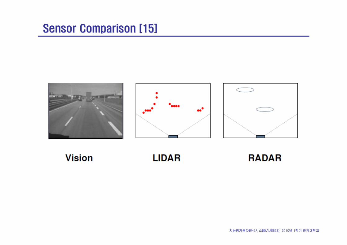
Sensor Comparison [15]Sensor Comparison [15]
지능형자동차인식시스템(AUE853), 2010년 1학기 한양대학교
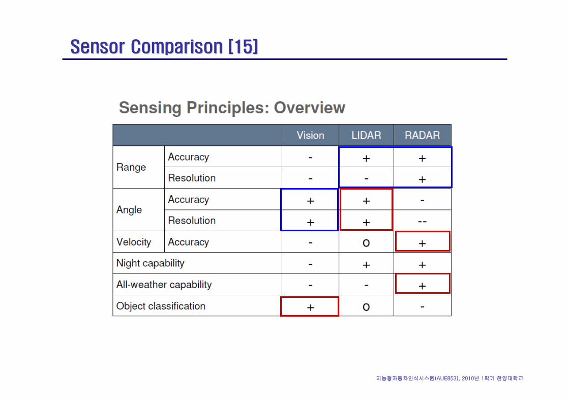
Sensor Comparison [15]Sensor Comparison [15]

지능형자동차인식시스템(AUE853), 2010년 1학기 한양대학교
밀리파밀리파 레이더레이더
지능형자동차인식시스템(AUE853), 2010년 1학기 한양대학교
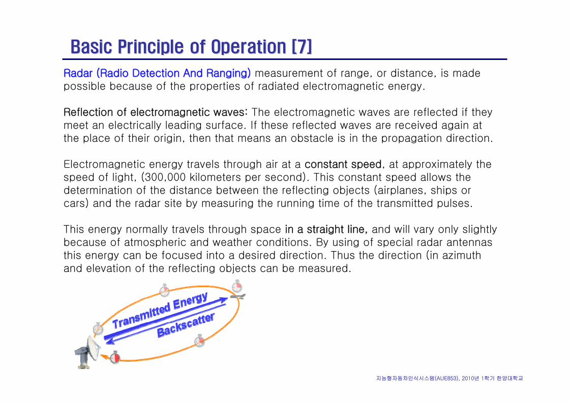
Radar (Radio Detection And Ranging)Radar (Radio Detection And Ranging) measurement of range, or distance, is made possible because of the properties of radiated electromagnetic energy.
Reflection of electromagnetic waves: The electromagnetic waves are reflected if they meet an electrically leading surface. If these reflected waves are received again at the place of their origin, then that means an obstacle is in the propagation direction.
Electromagnetic energy travels through air at a constant speed, at approximately the speed of light, (300,000 kilometers per second). This constant speed allows the determination of the distance between the reflecting objects (airplanes, ships or cars) and the radar site by measuring the running time of the transmitted pulses.
This energy normally travels through space in a straight line, and will vary only slightly because of atmospheric and weather conditions. By using of special radar antennas this energy can be focused into a desired direction. Thus the direction (in azimuthand elevation of the reflecting objects can be measured.
Basic Principle of Operation [7]Basic Principle of Operation [7]
지능형자동차인식시스템(AUE853), 2010년 1학기 한양대학교
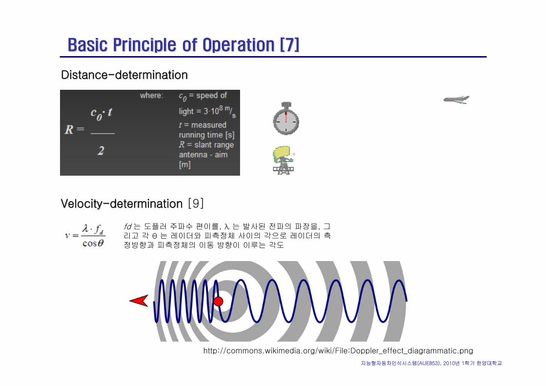
DistanceDistance--determinationdetermination
Basic Principle of Operation [7]Basic Principle of Operation [7]
VelocityVelocity--determinationdetermination [9]
http://commons.wikimedia.org/wiki/File:Doppler_effect_diagrammatic.png
fd 는 도플러 주파수 편이를, λ 는 발사된 전파의 파장을, 그리고 각 θ 는 레이더와 피측정체 사이의 각으로 레이더의 측정방향과 피측정체의 이동 방향이 이루는 각도
지능형자동차인식시스템(AUE853), 2010년 1학기 한양대학교
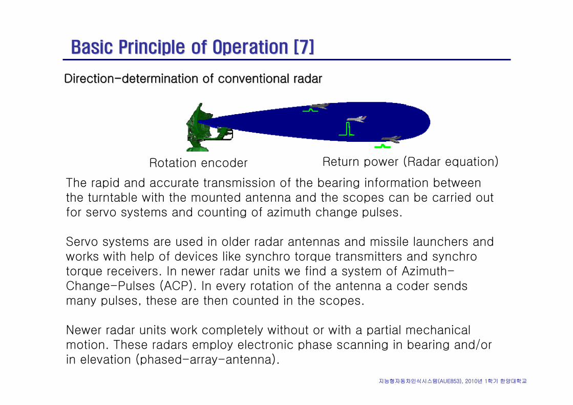
DirectionDirection--determination of conventional radardetermination of conventional radar
Basic Principle of Operation [7]Basic Principle of Operation [7]
The rapid and accurate transmission of the bearing information between the turntable with the mounted antenna and the scopes can be carried out for servo systems and counting of azimuth change pulses.
Servo systems are used in older radar antennas and missile launchers and works with help of devices like synchro torque transmitters and synchrotorque receivers. In newer radar units we find a system of Azimuth-Change-Pulses (ACP). In every rotation of the antenna a coder sends many pulses, these are then counted in the scopes.
Newer radar units work completely without or with a partial mechanical motion. These radars employ electronic phase scanning in bearing and/or in elevation (phased-array-antenna).
Rotation encoder Return power (Radar equation)
지능형자동차인식시스템(AUE853), 2010년 1학기 한양대학교
Wavelengths at Various Frequencies [1]Wavelengths at Various Frequencies [1]
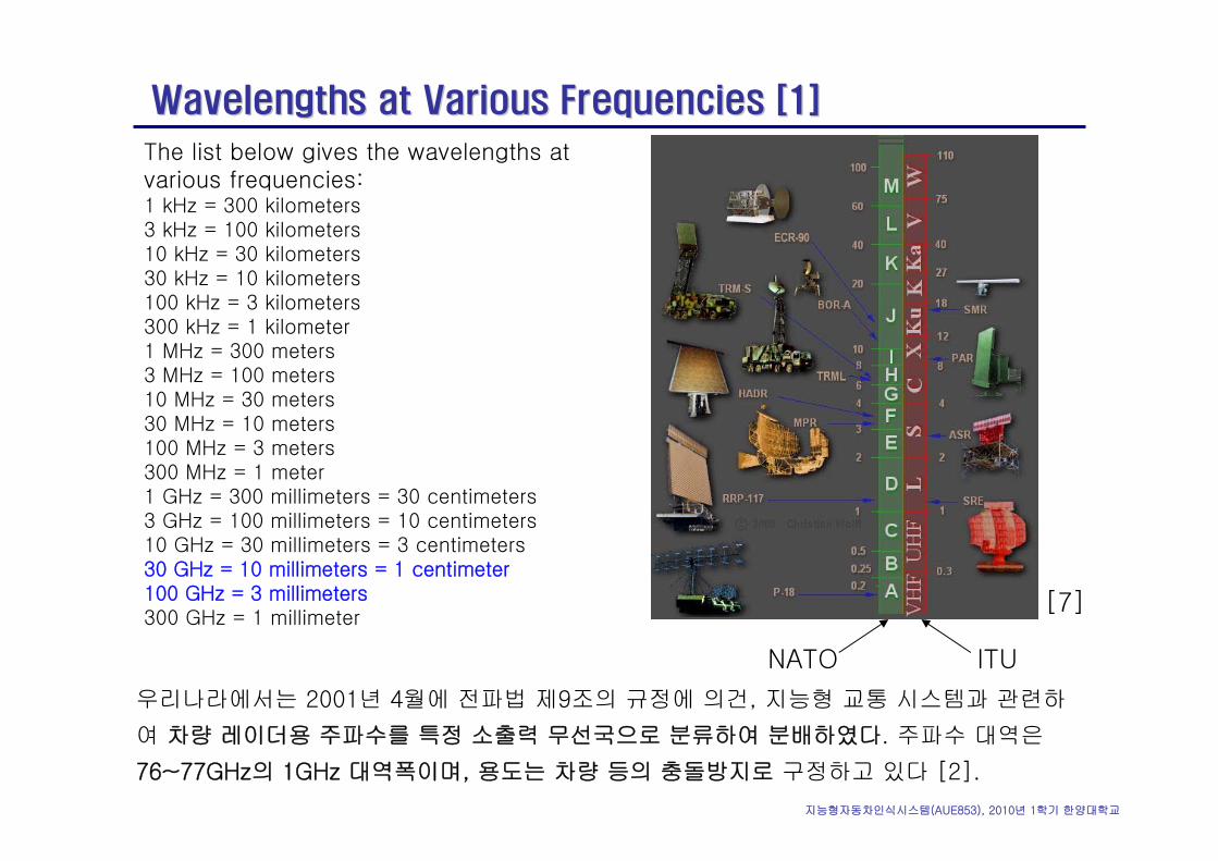
The list below gives the wavelengths at various frequencies:1 kHz = 300 kilometers 3 kHz = 100 kilometers 10 kHz = 30 kilometers 30 kHz = 10 kilometers 100 kHz = 3 kilometers 300 kHz = 1 kilometer 1 MHz = 300 meters 3 MHz = 100 meters 10 MHz = 30 meters 30 MHz = 10 meters 100 MHz = 3 meters 300 MHz = 1 meter 1 GHz = 300 millimeters = 30 centimeters 3 GHz = 100 millimeters = 10 centimeters 10 GHz = 30 millimeters = 3 centimeters 30 GHz = 10 millimeters = 1 centimeter 100 GHz = 3 millimeters 300 GHz = 1 millimeter
우리나라에서는 2001년 4월에 전파법 제9조의 규정에 의건, 지능형 교통 시스템과 관련하
여 차량 레이더용 주파수를 특정 소출력 무선국으로 분류하여 분배하였다. 주파수 대역은
76~77GHz의 1GHz 대역폭이며, 용도는 차량 등의 충돌방지로 구정하고 있다 [2].
ITUNATO
[7]
지능형자동차인식시스템(AUE853), 2010년 1학기 한양대학교
Dipole Antenna [1]Dipole Antenna [1]
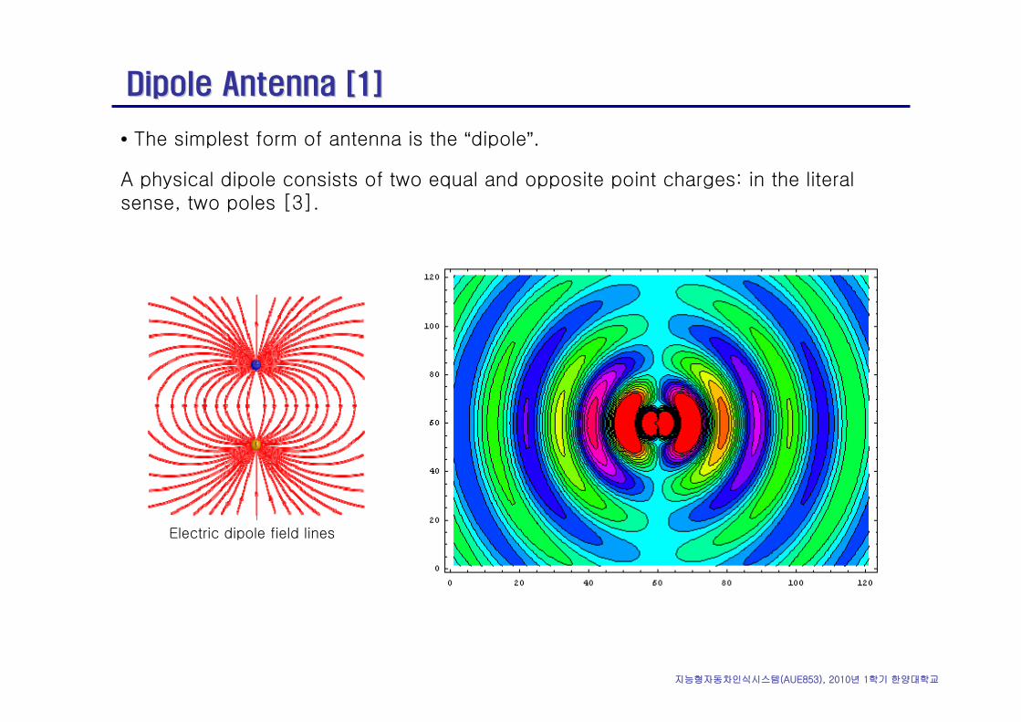
• The simplest form of antenna is the “dipole”.
A physical dipole consists of two equal and opposite point charges: in the literal sense, two poles [3].
Electric dipole field lines
지능형자동차인식시스템(AUE853), 2010년 1학기 한양대학교
Dipole Antenna [4]Dipole Antenna [4]
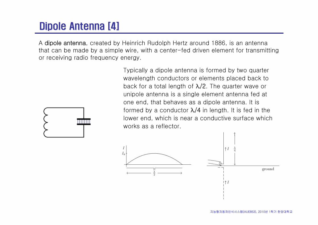
A dipole antenna, created by Heinrich Rudolph Hertz around 1886, is an antennathat can be made by a simple wire, with a center-fed driven element for transmitting or receiving radio frequency energy.
Typically a dipole antenna is formed by two quarter
wavelength conductors or elements placed back to
back for a total length of λ/2. The quarter wave or
unipole antenna is a single element antenna fed at
one end, that behaves as a dipole antenna. It is
formed by a conductor λ/4 in length. It is fed in the
lower end, which is near a conductive surface which
works as a reflector.
지능형자동차인식시스템(AUE853), 2010년 1학기 한양대학교
Parabolic Dish Antenna [5]Parabolic Dish Antenna [5]
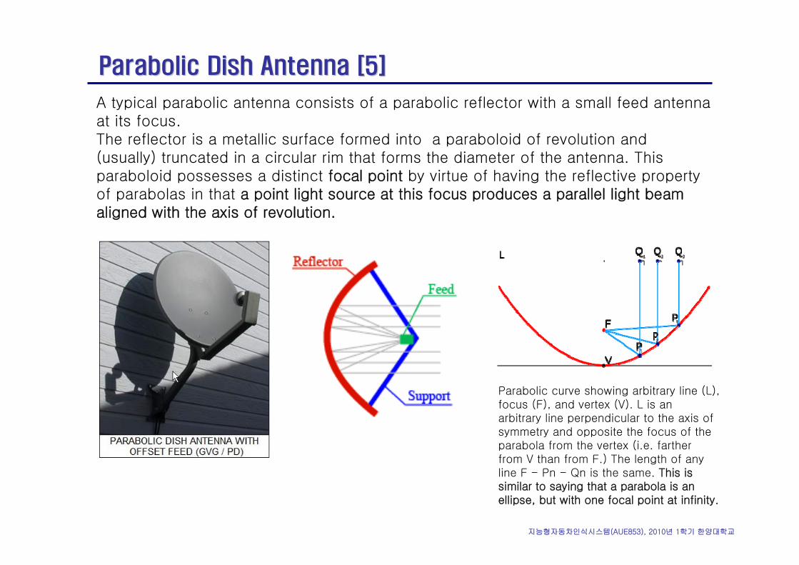
Parabolic curve showing arbitrary line (L), focus (F), and vertex (V). L is an arbitrary line perpendicular to the axis of symmetry and opposite the focus of the parabola from the vertex (i.e. farther from V than from F.) The length of any line F - Pn - Qn is the same. This is similar to saying that a parabola is an ellipse, but with one focal point at infinity.
A typical parabolic antenna consists of a parabolic reflector with a small feed antennaat its focus.The reflector is a metallic surface formed into a paraboloid of revolution and (usually) truncated in a circular rim that forms the diameter of the antenna. This paraboloid possesses a distinct focal point by virtue of having the reflective property of parabolas in that a point light source at this focus produces a parallel light beam aligned with the axis of revolution.
지능형자동차인식시스템(AUE853), 2010년 1학기 한양대학교
Parabolic Dish Antenna [5]Parabolic Dish Antenna [5]
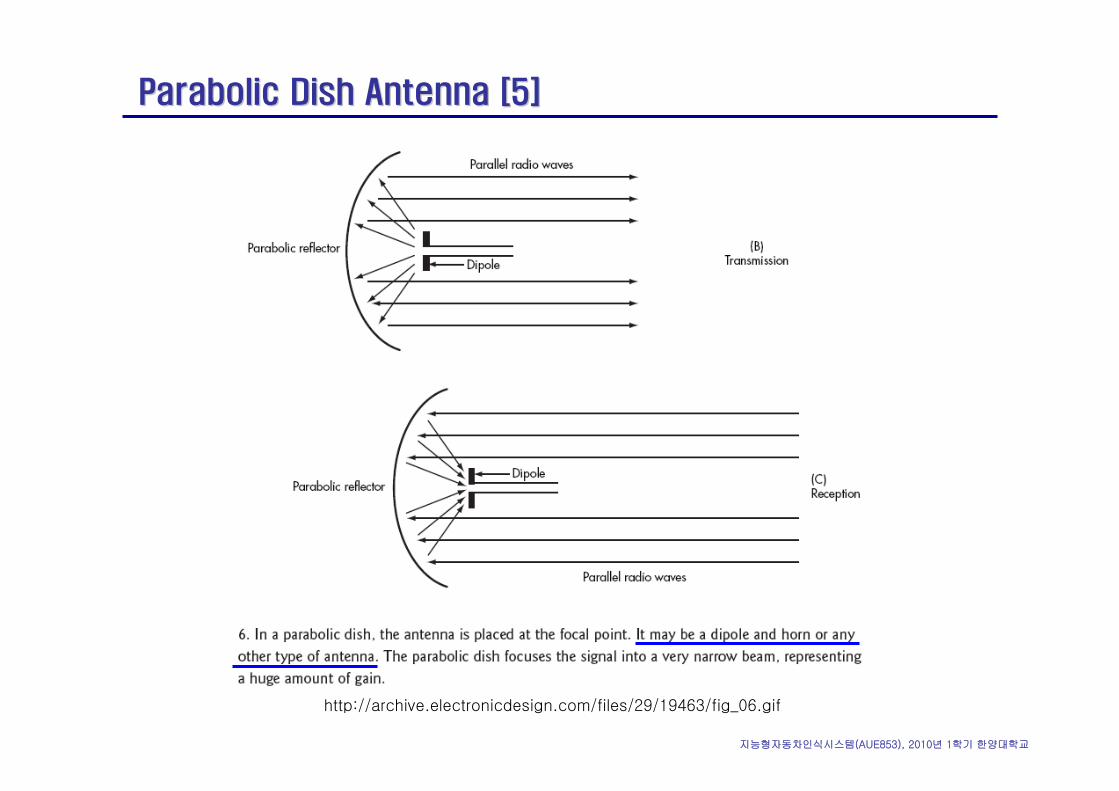
http://archive.electronicdesign.com/files/29/19463/fig_06.gif
지능형자동차인식시스템(AUE853), 2010년 1학기 한양대학교
YagiYagi Antenna [8]Antenna [8]
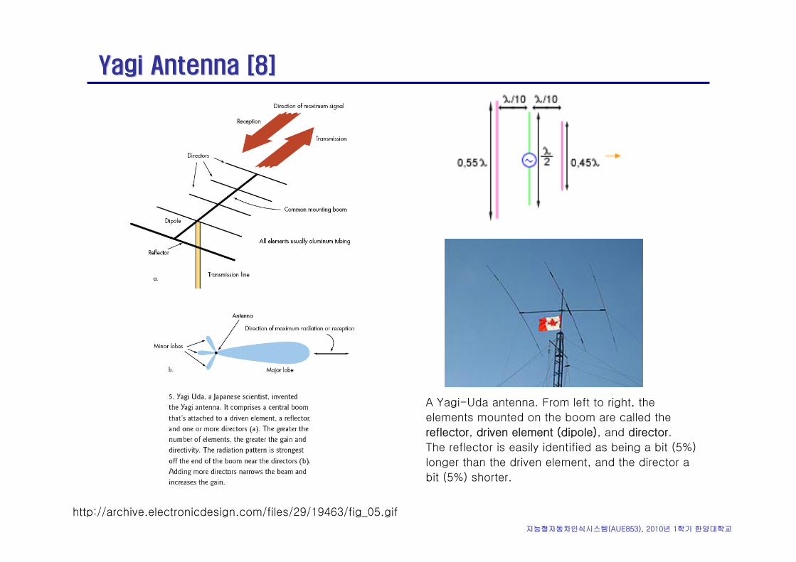
http://archive.electronicdesign.com/files/29/19463/fig_05.gif
A Yagi-Uda antenna. From left to right, the
elements mounted on the boom are called the
reflector, driven element (dipole), and director.
The reflector is easily identified as being a bit (5%)
longer than the driven element, and the director a
bit (5%) shorter.
지능형자동차인식시스템(AUE853), 2010년 1학기 한양대학교
Patch Antenna [6]Patch Antenna [6]
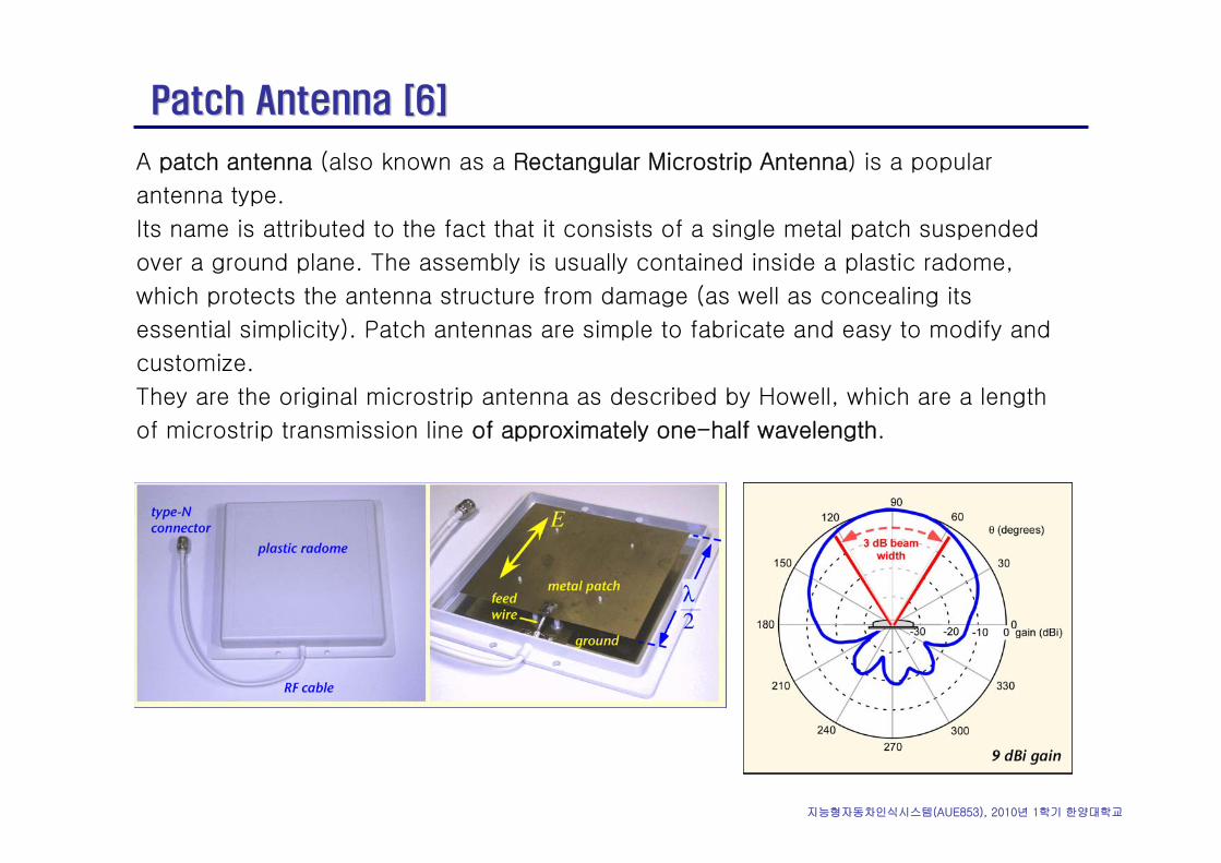
A patch antenna (also known as a Rectangular Microstrip Antenna) is a popular
antenna type.
Its name is attributed to the fact that it consists of a single metal patch suspended
over a ground plane. The assembly is usually contained inside a plastic radome,
which protects the antenna structure from damage (as well as concealing its
essential simplicity). Patch antennas are simple to fabricate and easy to modify and
customize.
They are the original microstrip antenna as described by Howell, which are a length
of microstrip transmission line of approximately one-half wavelength.
지능형자동차인식시스템(AUE853), 2010년 1학기 한양대학교
MicrostripMicrostrip Antenna [10]Antenna [10]
In telecommunication, there are several types of microstrip antennas (also known as printed antennas) the most common of which is the microstrippatch antenna or patch antenna. A patch antenna is a narrowband, wide-beam antenna fabricated by etching the antenna element pattern in metal trace bonded to an insulating dielectric substrate with a continuous metal layer bonded to the opposite side of the substrate which forms agroundplane. Common microstrip antenna radiator shapes are square, rectangular, circular and elliptical, but any continuous shape is possible.
• Microstrip antennas are also relatively inexpensive to manufacture and design because of the simple 2-dimensional physical geometry.
• Such an array of patch antennas is an easy way to make a phased array of antennas with dynamic beamforming ability.
지능형자동차인식시스템(AUE853), 2010년 1학기 한양대학교
MicrostripMicrostrip Antenna [10]Antenna [10]
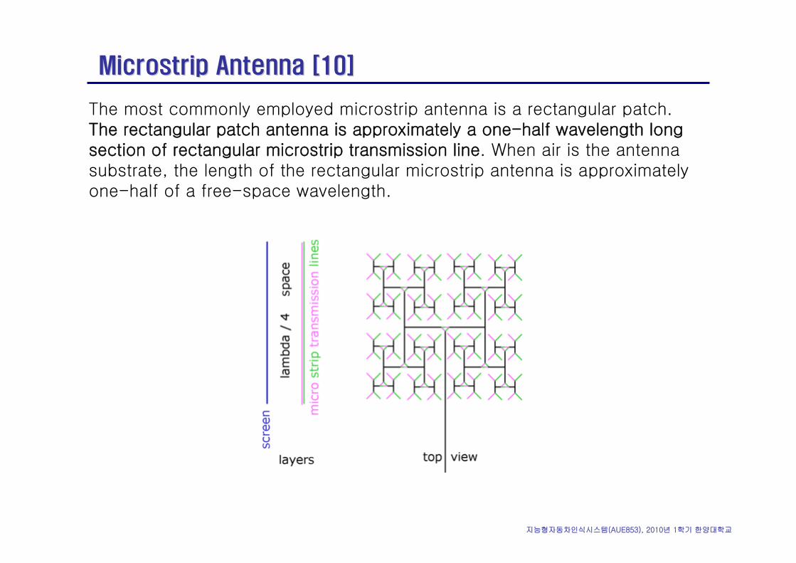
The most commonly employed microstrip antenna is a rectangular patch. The rectangular patch antenna is approximately a one-half wavelength long section of rectangular microstrip transmission line. When air is the antenna substrate, the length of the rectangular microstrip antenna is approximately one-half of a free-space wavelength.
지능형자동차인식시스템(AUE853), 2010년 1학기 한양대학교
MicrostripMicrostrip Antenna [10]Antenna [10]
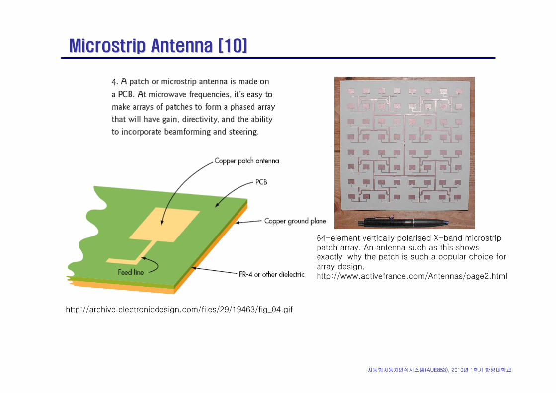
64-element vertically polarised X-band microstrippatch array. An antenna such as this shows exactly why the patch is such a popular choice for array design.http://www.activefrance.com/Antennas/page2.html
http://archive.electronicdesign.com/files/29/19463/fig_04.gif
지능형자동차인식시스템(AUE853), 2010년 1학기 한양대학교
Phase and Interference [1]Phase and Interference [1]
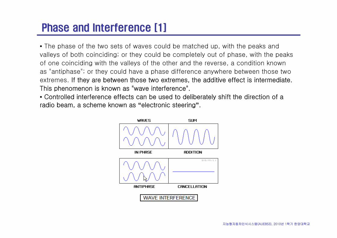
• The phase of the two sets of waves could be matched up, with the peaks and
valleys of both coinciding; or they could be completely out of phase, with the peaks
of one coinciding with the valleys of the other and the reverse, a condition known
as "antiphase"; or they could have a phase difference anywhere between those two
extremes. If they are between those two extremes, the additive effect is intermediate.
This phenomenon is known as "wave interference".
• Controlled interference effects can be used to deliberately shift the direction of a radio beam, a scheme known as “electronic steering”.
지능형자동차인식시스템(AUE853), 2010년 1학기 한양대학교
Phased Array Antenna [7]Phased Array Antenna [7]
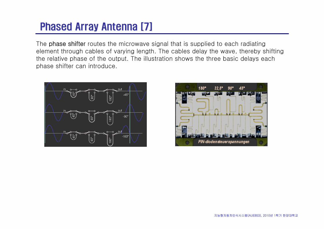
The phase shifter routes the microwave signal that is supplied to each radiating element through cables of varying length. The cables delay the wave, thereby shifting the relative phase of the output. The illustration shows the three basic delays each phase shifter can introduce.
지능형자동차인식시스템(AUE853), 2010년 1학기 한양대학교
Phased Array Antenna [7]Phased Array Antenna [7]
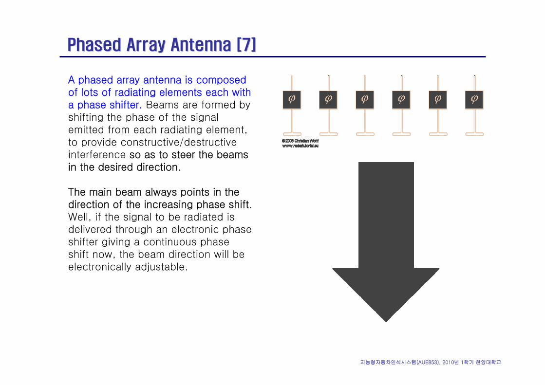
A phased array antenna is composed of lots of radiating elements each with a phase shifter. Beams are formed by shifting the phase of the signal emitted from each radiating element, to provide constructive/destructive interference so as to steer the beams in the desired direction.
The main beam always points in the direction of the increasing phase shift. Well, if the signal to be radiated is delivered through an electronic phase shifter giving a continuous phase shift now, the beam direction will be electronically adjustable.
지능형자동차인식시스템(AUE853), 2010년 1학기 한양대학교
Phased Array Antenna [7]Phased Array Antenna [7]
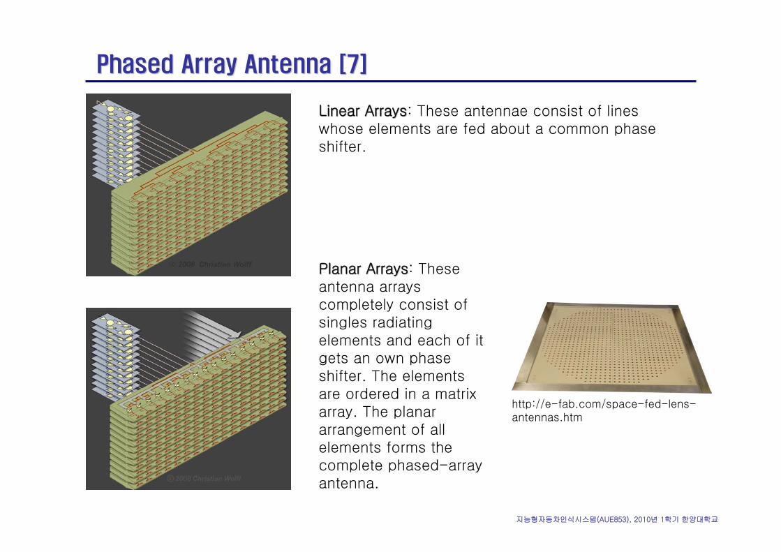
Linear ArraysLinear Arrays: These antennae consist of lines whose elements are fed about a common phase shifter.
Planar ArraysPlanar Arrays: These antenna arrays completely consist of singles radiating elements and each of it gets an own phase shifter. The elements are ordered in a matrix array. The planar arrangement of all elements forms the complete phased-array antenna.
http://e-fab.com/space-fed-lens-antennas.htm
지능형자동차인식시스템(AUE853), 2010년 1학기 한양대학교
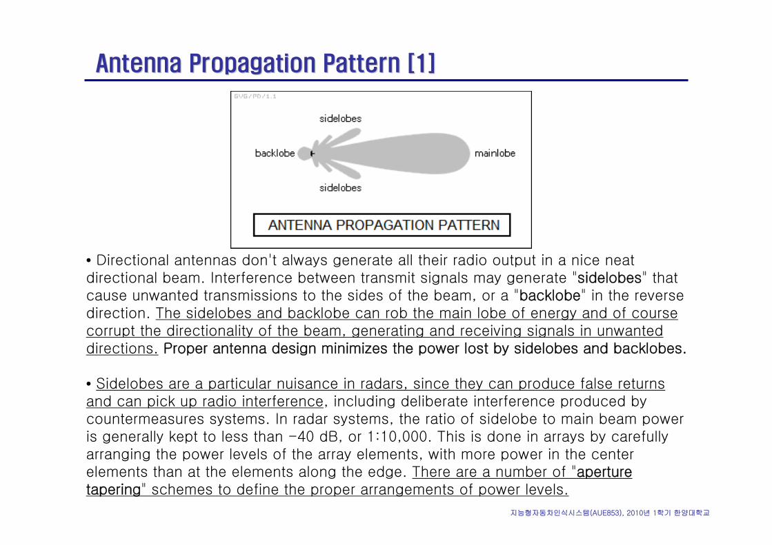
Antenna Propagation Pattern [1]Antenna Propagation Pattern [1]
• Directional antennas don't always generate all their radio output in a nice neat directional beam. Interference between transmit signals may generate "sidelobes" that cause unwanted transmissions to the sides of the beam, or a "backlobe" in the reverse direction. The sidelobes and backlobe can rob the main lobe of energy and of course corrupt the directionality of the beam, generating and receiving signals in unwanted directions. Proper antenna design minimizes the power lost by sidelobes and backlobes.
• Sidelobes are a particular nuisance in radars, since they can produce false returns and can pick up radio interference, including deliberate interference produced by countermeasures systems. In radar systems, the ratio of sidelobe to main beam power is generally kept to less than -40 dB, or 1:10,000. This is done in arrays by carefully arranging the power levels of the array elements, with more power in the center elements than at the elements along the edge. There are a number of "aperture tapering" schemes to define the proper arrangements of power levels.
지능형자동차인식시스템(AUE853), 2010년 1학기 한양대학교
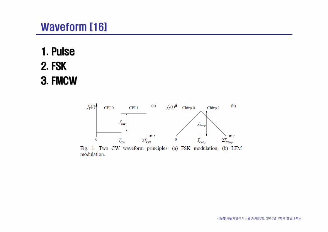
Waveform [16]Waveform [16]
1.1. PulsePulse
2.2. FSKFSK
3.3. FMCWFMCW
지능형자동차인식시스템(AUE853), 2010년 1학기 한양대학교
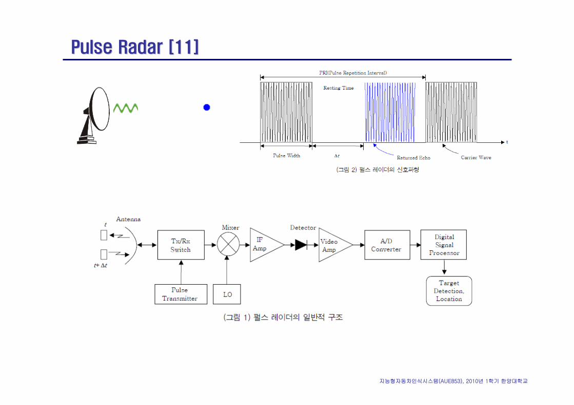
Pulse Radar [11]Pulse Radar [11]
지능형자동차인식시스템(AUE853), 2010년 1학기 한양대학교
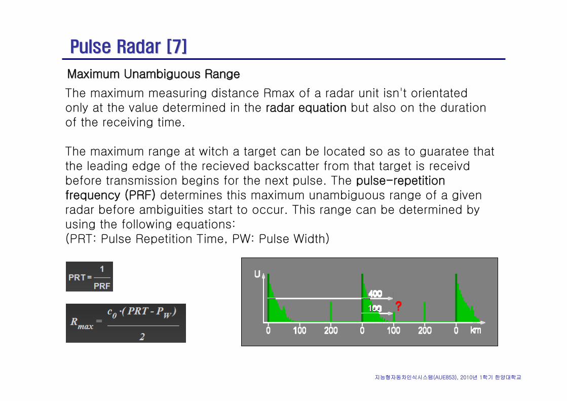
Pulse Radar [7]Pulse Radar [7]
Maximum Unambiguous Range Maximum Unambiguous Range
The maximum measuring distance Rmax of a radar unit isn't orientated only at the value determined in the radar equation but also on the duration of the receiving time.
The maximum range at witch a target can be located so as to guaratee that the leading edge of the recieved backscatter from that target is receivdbefore transmission begins for the next pulse. The pulse-repetition frequency (PRF) determines this maximum unambiguous range of a given radar before ambiguities start to occur. This range can be determined by using the following equations: (PRT: Pulse Repetition Time, PW: Pulse Width)
지능형자동차인식시스템(AUE853), 2010년 1학기 한양대학교
Pulse Radar [7]Pulse Radar [7]
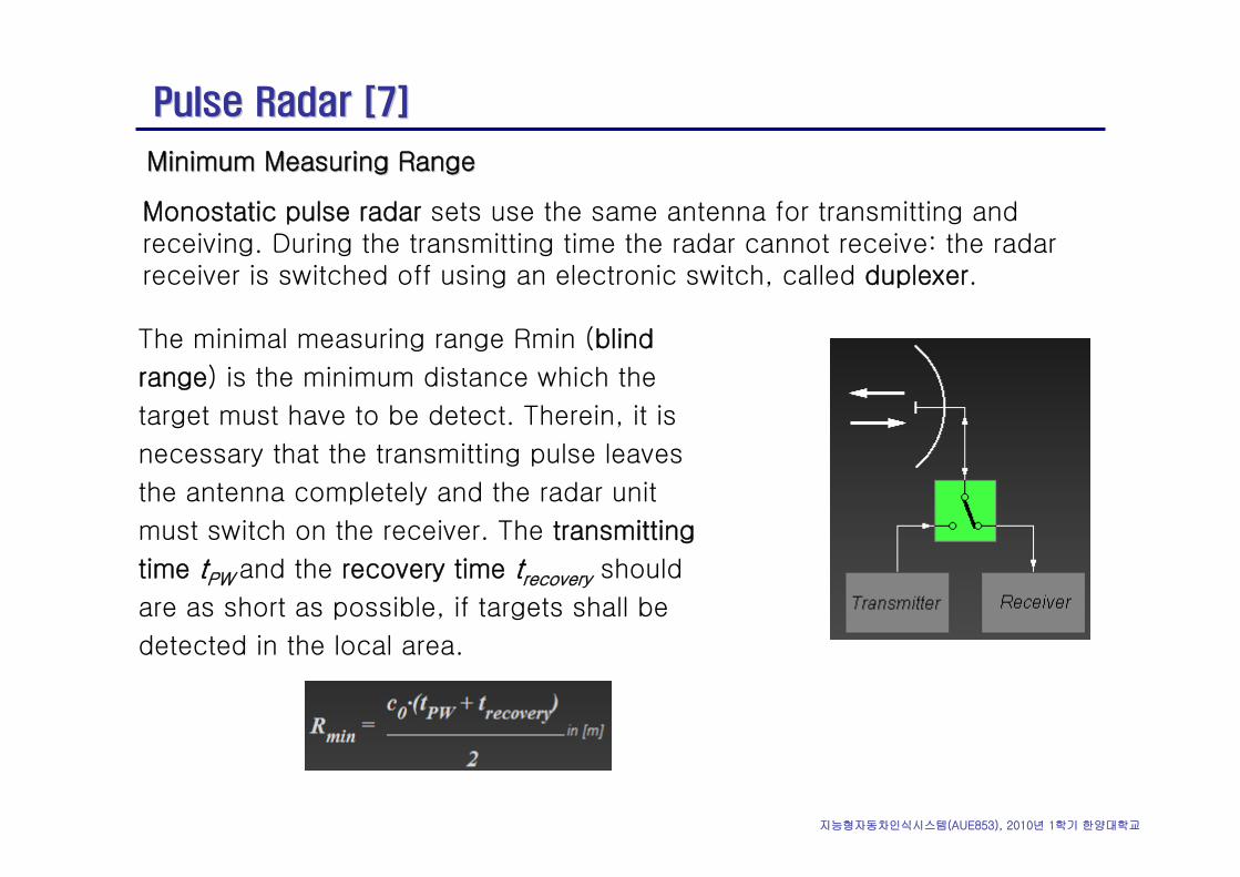
Minimum Measuring RangeMinimum Measuring Range
Monostatic pulse radar sets use the same antenna for transmitting and receiving. During the transmitting time the radar cannot receive: the radar receiver is switched off using an electronic switch, called duplexer.
The minimal measuring range Rmin (blind
range) is the minimum distance which the
target must have to be detect. Therein, it is
necessary that the transmitting pulse leaves
the antenna completely and the radar unit
must switch on the receiver. The transmitting
time tPW and the recovery time trecovery should
are as short as possible, if targets shall be
detected in the local area.
지능형자동차인식시스템(AUE853), 2010년 1학기 한양대학교
Pulse Radar [7]Pulse Radar [7]
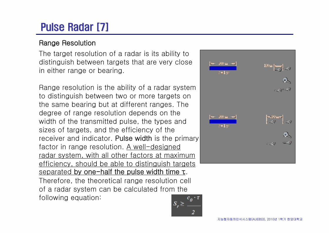
Range Resolution Range Resolution
The target resolution of a radar is its ability to distinguish between targets that are very close in either range or bearing.
Range resolution is the ability of a radar system to distinguish between two or more targets on the same bearing but at different ranges. The degree of range resolution depends on the width of the transmitted pulse, the types and sizes of targets, and the efficiency of the receiver and indicator. Pulse width is the primary factor in range resolution. A well-designed radar system, with all other factors at maximum efficiency, should be able to distinguish targets separated by one-half the pulse width time τ. Therefore, the theoretical range resolution cell of a radar system can be calculated from the following equation:
지능형자동차인식시스템(AUE853), 2010년 1학기 한양대학교
Radar Equation [7]Radar Equation [7]
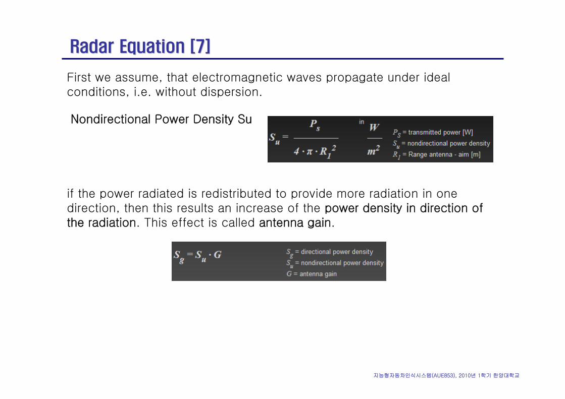
First we assume, that electromagnetic waves propagate under ideal conditions, i.e. without dispersion.
Nondirectional Power Density Su
if the power radiated is redistributed to provide more radiation in one direction, then this results an increase of the power density in direction of the radiation. This effect is called antenna gain.
지능형자동차인식시스템(AUE853), 2010년 1학기 한양대학교
Radar Equation [7]Radar Equation [7]
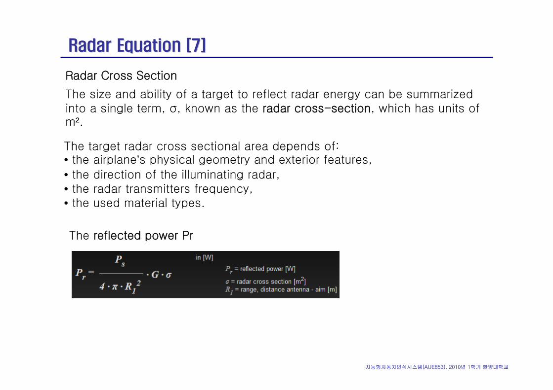
Radar Cross Section
The size and ability of a target to reflect radar energy can be summarized into a single term, σ, known as the radar cross-section, which has units of m².
The target radar cross sectional area depends of:• the airplane’s physical geometry and exterior features, • the direction of the illuminating radar, • the radar transmitters frequency, • the used material types.
The reflected power Pr
지능형자동차인식시스템(AUE853), 2010년 1학기 한양대학교
Radar Equation [7]Radar Equation [7]
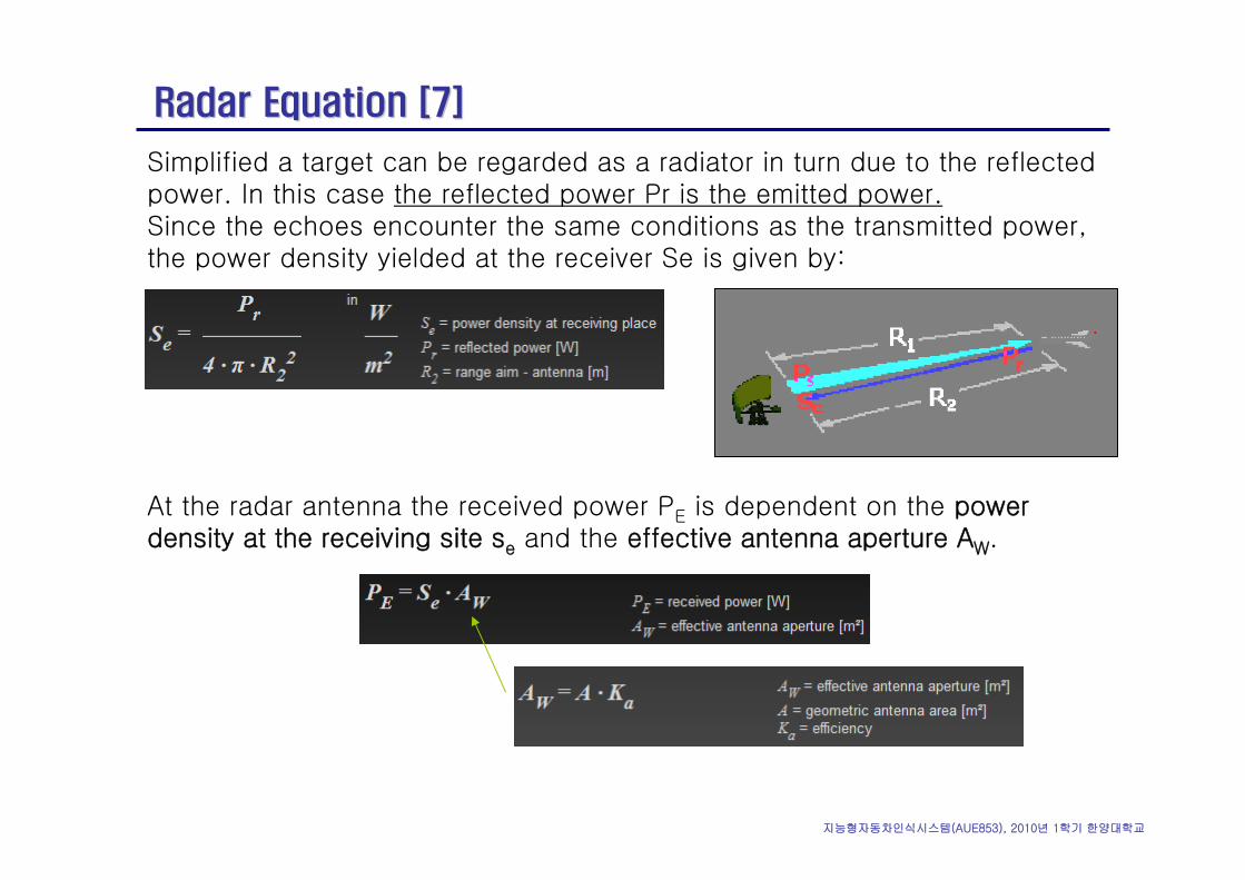
Simplified a target can be regarded as a radiator in turn due to the reflected power. In this case the reflected power Pr is the emitted power.Since the echoes encounter the same conditions as the transmitted power, the power density yielded at the receiver Se is given by:
At the radar antenna the received power PE is dependent on the power density at the receiving site se and the effective antenna aperture AW.
지능형자동차인식시스템(AUE853), 2010년 1학기 한양대학교
Radar Equation [7]Radar Equation [7]
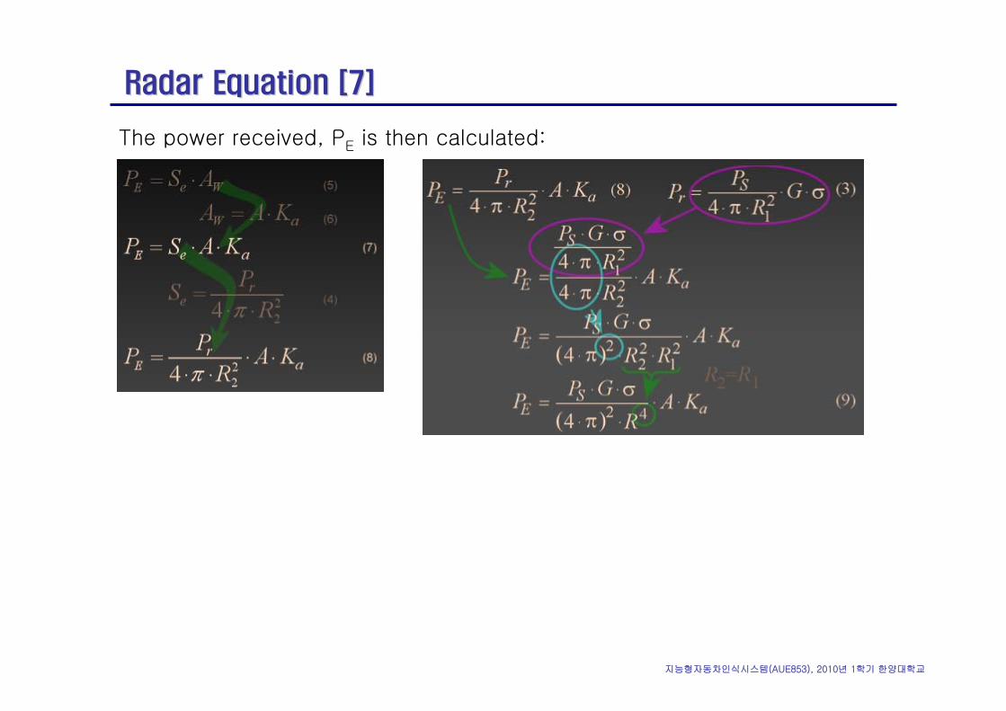
The power received, PE is then calculated:
지능형자동차인식시스템(AUE853), 2010년 1학기 한양대학교
Radar Equation [7]Radar Equation [7]
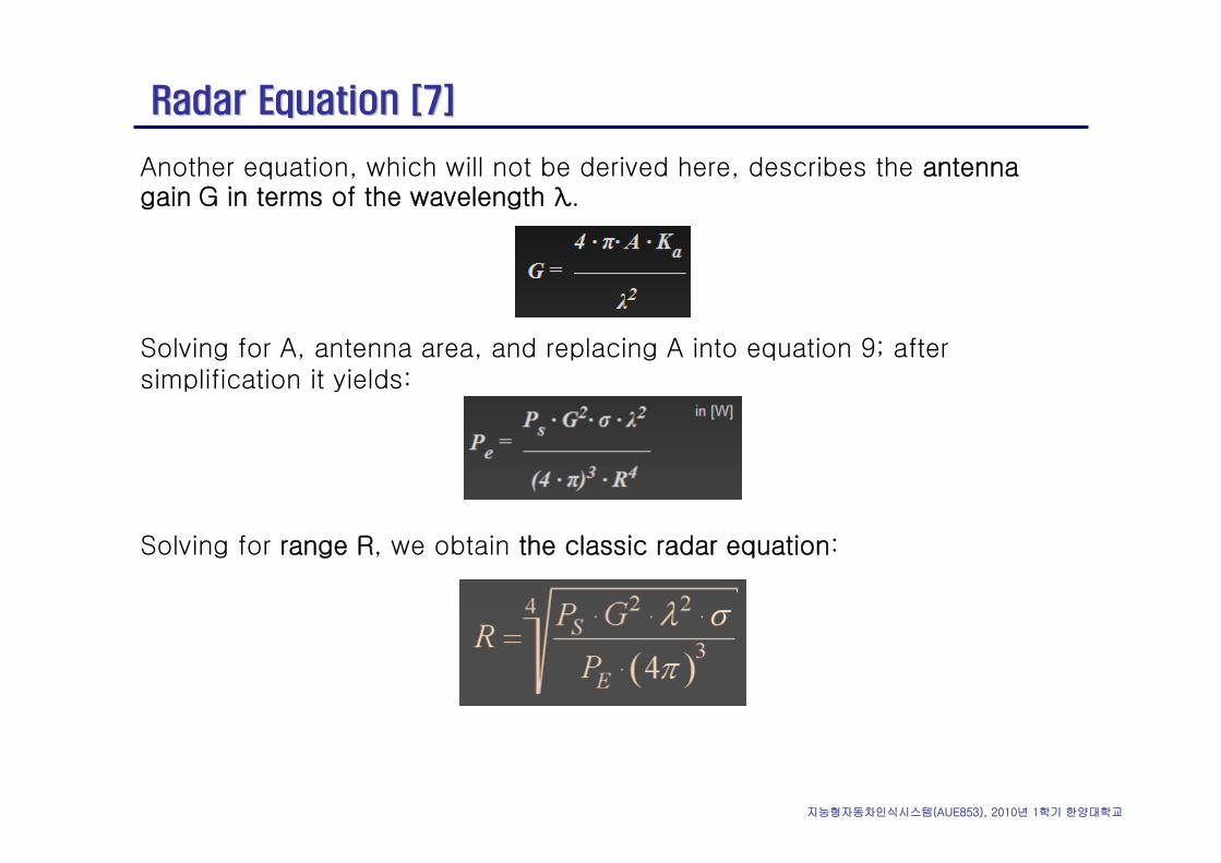
Another equation, which will not be derived here, describes the antenna gain G in terms of the wavelength λ.
Solving for A, antenna area, and replacing A into equation 9; after simplification it yields:
Solving for range R, we obtain the classic radar equation:
지능형자동차인식시스템(AUE853), 2010년 1학기 한양대학교
DOA Estimation [20]DOA Estimation [20]
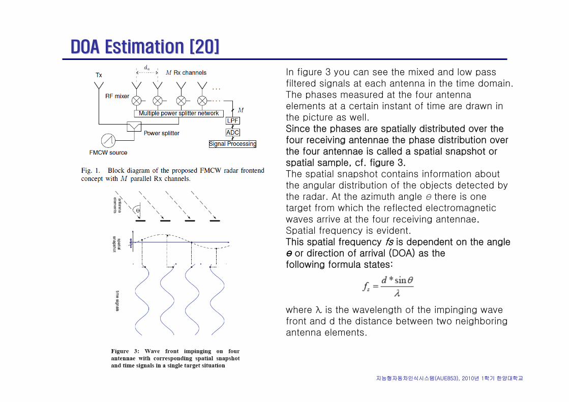
In figure 3 you can see the mixed and low passfiltered signals at each antenna in the time domain. The phases measured at the four antenna elements at a certain instant of time are drawn in the picture as well.Since the phases are spatially distributed over the four receiving antennae the phase distribution over the four antennae is called a spatial snapshot or spatial sample, cf. figure 3.The spatial snapshot contains information about the angular distribution of the objects detected by the radar. At the azimuth angle Ө there is one target from which the reflected electromagnetic waves arrive at the four receiving antennae.Spatial frequency is evident.This spatial frequency fs is dependent on the angle Ө or direction of arrival (DOA) as thefollowing formula states:
where λ is the wavelength of the impinging wave front and d the distance between two neighboring antenna elements.
지능형자동차인식시스템(AUE853), 2010년 1학기 한양대학교
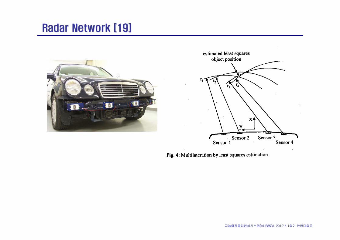
Radar Network [19]Radar Network [19]
지능형자동차인식시스템(AUE853), 2010년 1학기 한양대학교
Direction EstimationDirection Estimation
1.1. Beam steering by mechanical rotation and encoder, DirectionBeam steering by mechanical rotation and encoder, Direction--
determination by reflected powerdetermination by reflected power
2.2. Digital beam forming by transceiver array: electronic steeringDigital beam forming by transceiver array: electronic steering
3.3. DOA estimation by receiver arrayDOA estimation by receiver array
4.4. MultiMulti--laterationlateration by sensor arrayby sensor array
지능형자동차인식시스템(AUE853), 2010년 1학기 한양대학교
Pure FSK [16]Pure FSK [16]
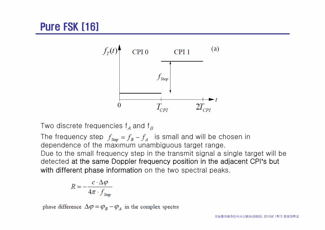
Two discrete frequencies fA and fB
The frequency step is small and will be chosen in dependence of the maximum unambiguous target range.Due to the small frequency step in the transmit signal a single target will be detected at the same Doppler frequency position in the adjacent CPI’s but with different phase information on the two spectral peaks.
지능형자동차인식시스템(AUE853), 2010년 1학기 한양대학교
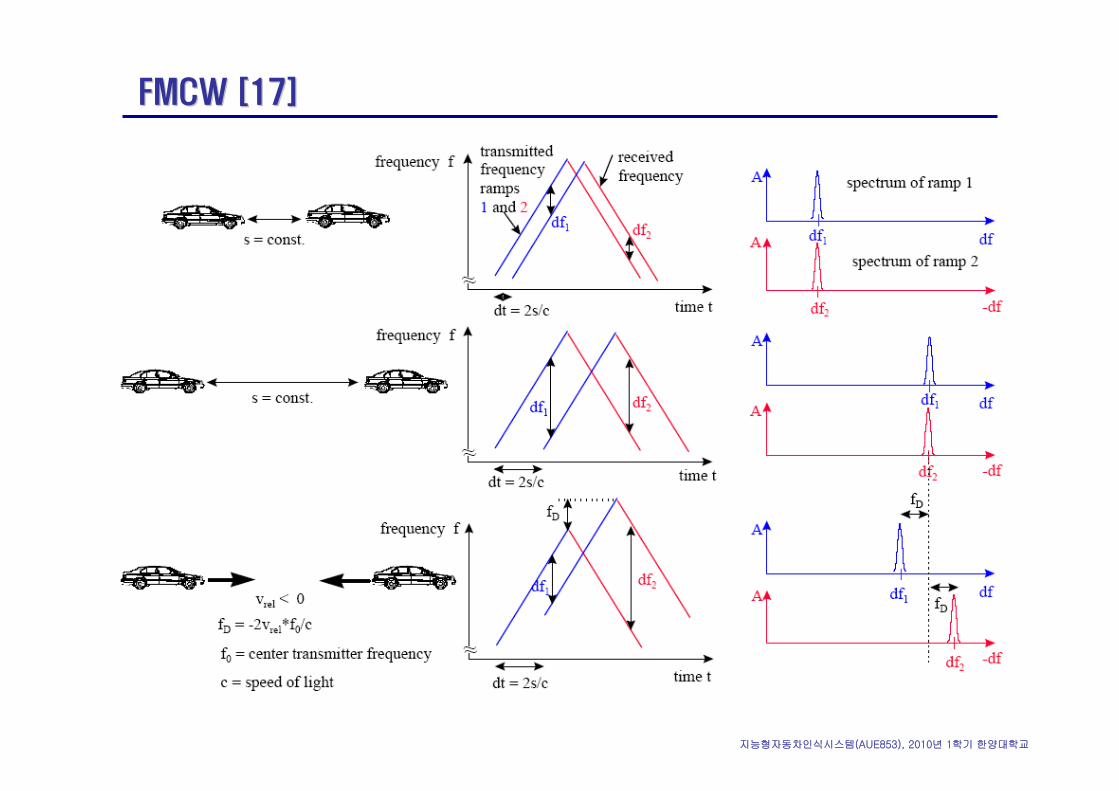
FMCW [17]FMCW [17]
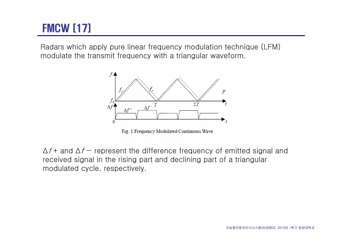
Radars which apply pure linear frequency modulation technique (LFM) modulate the transmit frequency with a triangular waveform.
Δf + and Δf − represent the difference frequency of emitted signal and received signal in the rising part and declining part of a triangular modulated cycle, respectively.
지능형자동차인식시스템(AUE853), 2010년 1학기 한양대학교
FMCW [17]FMCW [17]
지능형자동차인식시스템(AUE853), 2010년 1학기 한양대학교
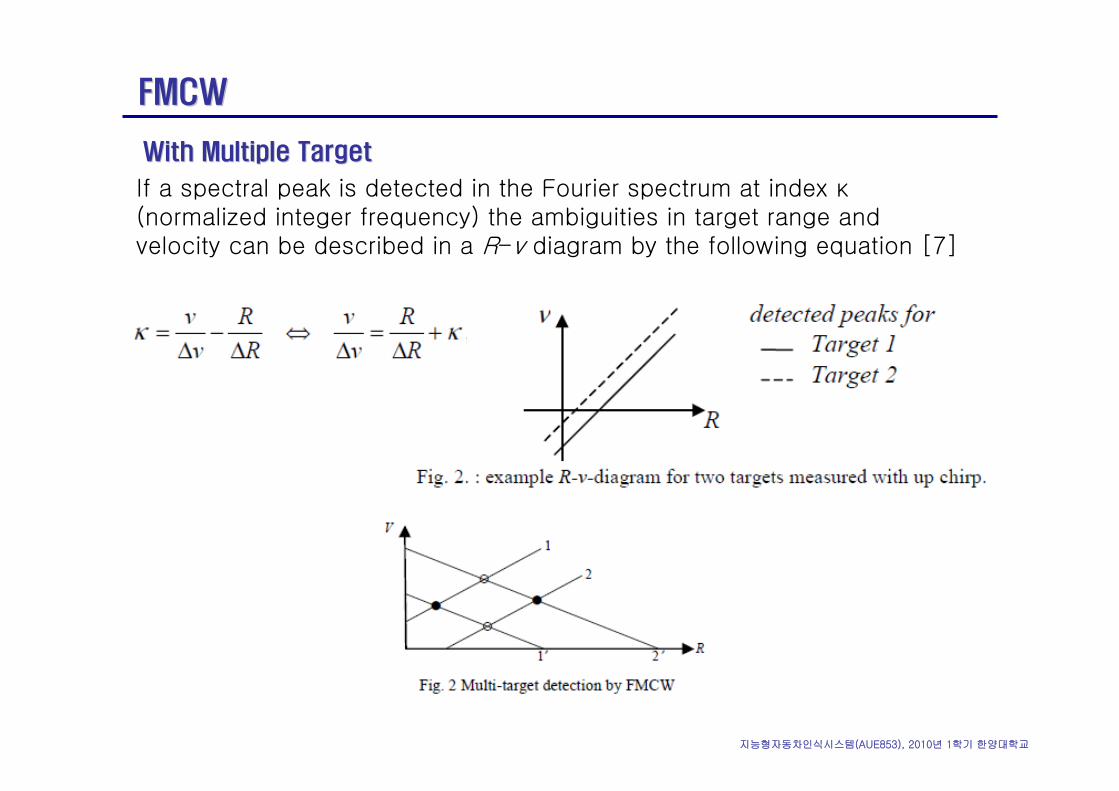
FMCWFMCW
If a spectral peak is detected in the Fourier spectrum at index κ(normalized integer frequency) the ambiguities in target range and velocity can be described in a R-v diagram by the following equation [7]
With Multiple TargetWith Multiple Target
지능형자동차인식시스템(AUE853), 2010년 1학기 한양대학교
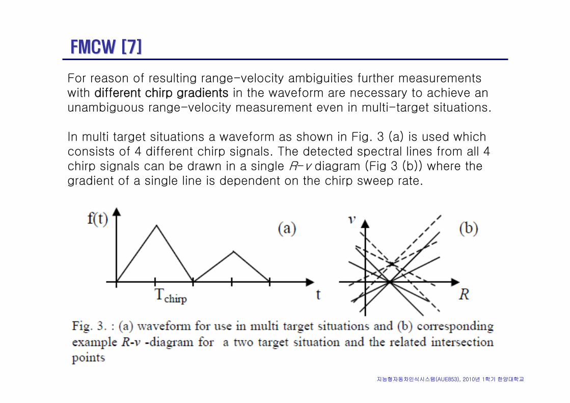
FMCW [7]FMCW [7]
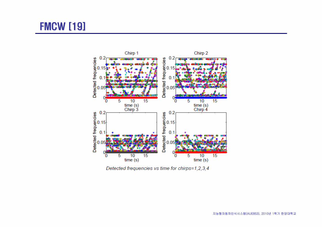
For reason of resulting range-velocity ambiguities further measurements with different chirp gradients in the waveform are necessary to achieve an unambiguous range-velocity measurement even in multi-target situations.
In multi target situations a waveform as shown in Fig. 3 (a) is used which consists of 4 different chirp signals. The detected spectral lines from all 4 chirp signals can be drawn in a single R-v diagram (Fig 3 (b)) where the gradient of a single line is dependent on the chirp sweep rate.
지능형자동차인식시스템(AUE853), 2010년 1학기 한양대학교
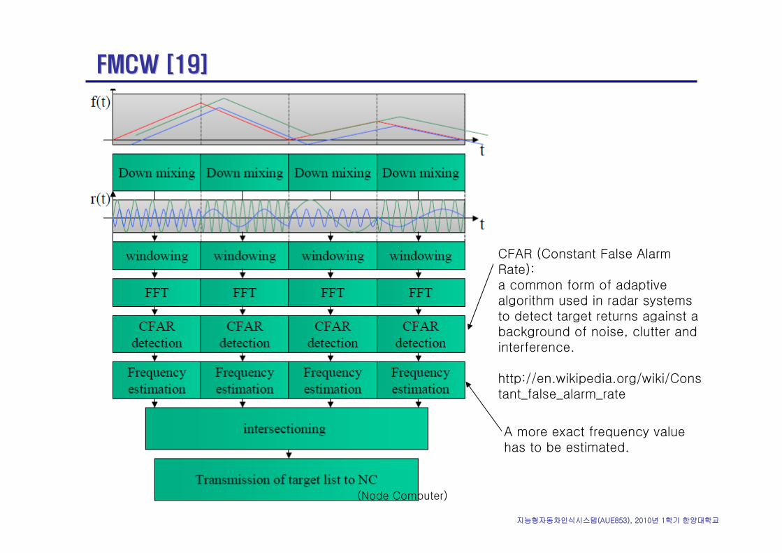
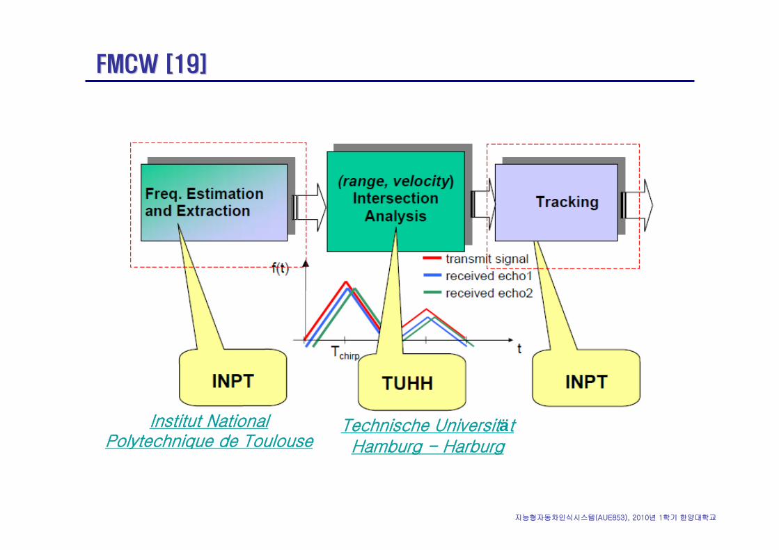
FMCW [19]FMCW [19]
CFAR (Constant False Alarm Rate):a common form of adaptive algorithm used in radar systems to detect target returns against a background of noise, clutter and interference.
http://en.wikipedia.org/wiki/Constant_false_alarm_rate
(Node Computer)
A more exact frequency value has to be estimated.
지능형자동차인식시스템(AUE853), 2010년 1학기 한양대학교
FMCW [19]FMCW [19]
Institut National Polytechnique de Toulouse
Technische UniversitätHamburg - Harburg
지능형자동차인식시스템(AUE853), 2010년 1학기 한양대학교
FMCW [19]FMCW [19]
지능형자동차인식시스템(AUE853), 2010년 1학기 한양대학교
FMCW [19]FMCW [19]
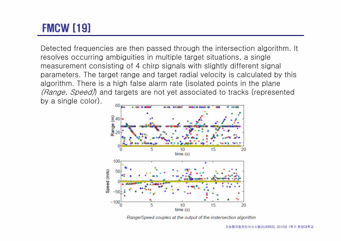
Detected frequencies are then passed through the intersection algorithm. It resolves occurring ambiguities in multiple target situations, a single measurement consisting of 4 chirp signals with slightly different signal parameters. The target range and target radial velocity is calculated by this algorithm. There is a high false alarm rate (isolated points in the plane (Range, Speed)) and targets are not yet associated to tracks (represented by a single color).
지능형자동차인식시스템(AUE853), 2010년 1학기 한양대학교
FMCW [19]FMCW [19]
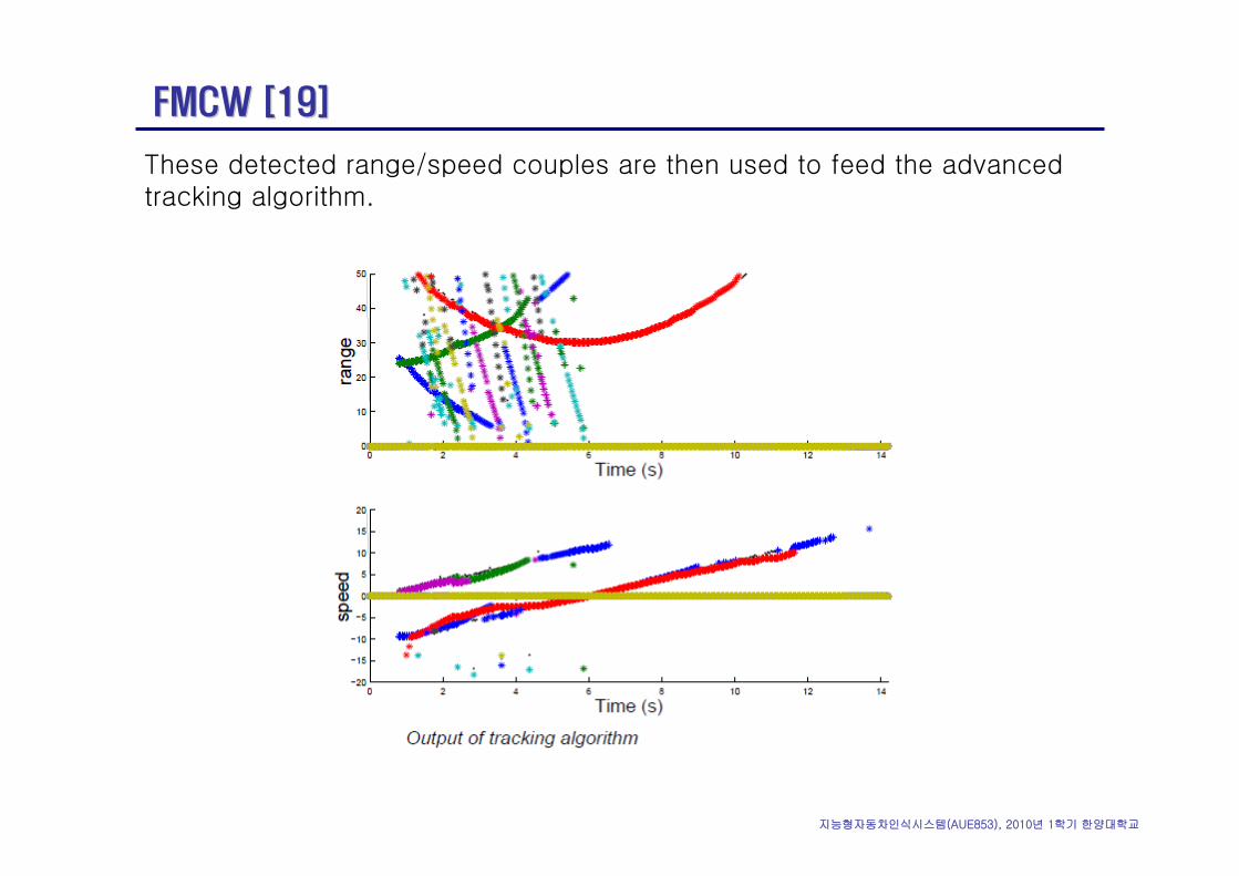
These detected range/speed couples are then used to feed the advanced tracking algorithm.
지능형자동차인식시스템(AUE853), 2010년 1학기 한양대학교
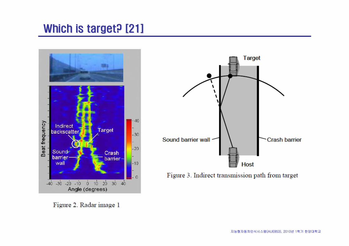
Which is target? [21]Which is target? [21]
지능형자동차인식시스템(AUE853), 2010년 1학기 한양대학교
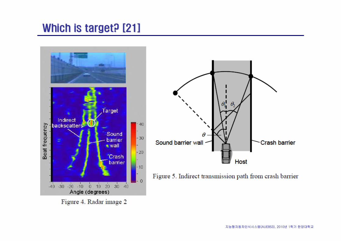
Which is target? [21]Which is target? [21]
지능형자동차인식시스템(AUE853), 2010년 1학기 한양대학교
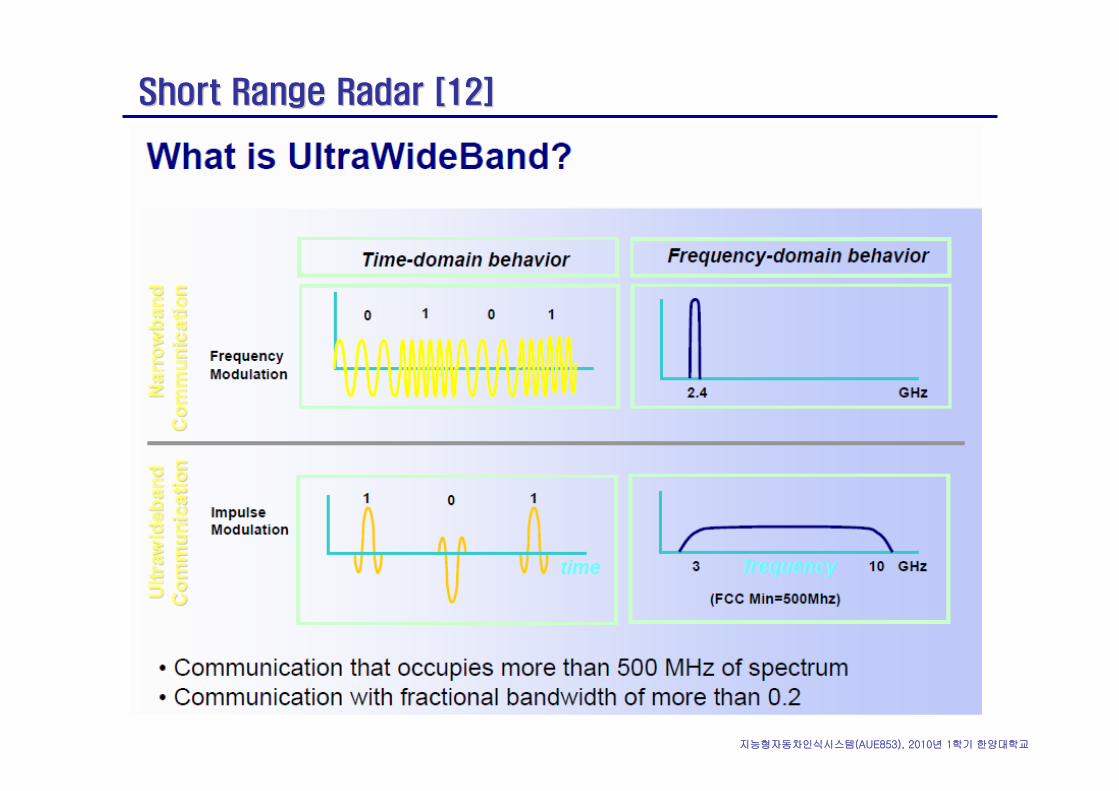
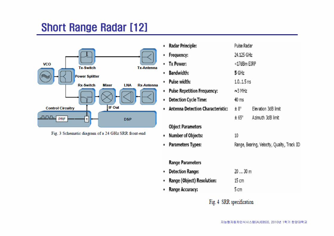
Short Range Radar [12]Short Range Radar [12]
지능형자동차인식시스템(AUE853), 2010년 1학기 한양대학교
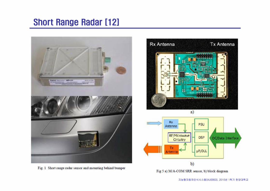
Short Range Radar [12]Short Range Radar [12]
지능형자동차인식시스템(AUE853), 2010년 1학기 한양대학교
Short Range Radar [12]Short Range Radar [12]
지능형자동차인식시스템(AUE853), 2010년 1학기 한양대학교
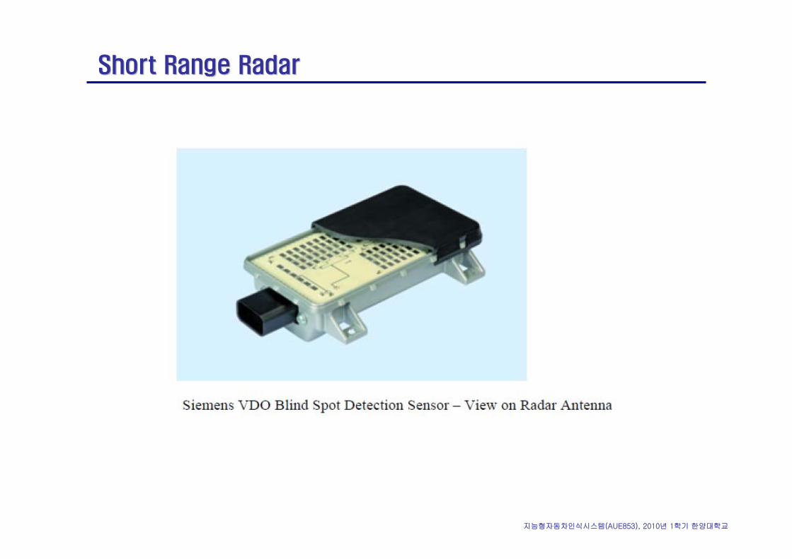
Short Range RadarShort Range Radar
지능형자동차인식시스템(AUE853), 2010년 1학기 한양대학교
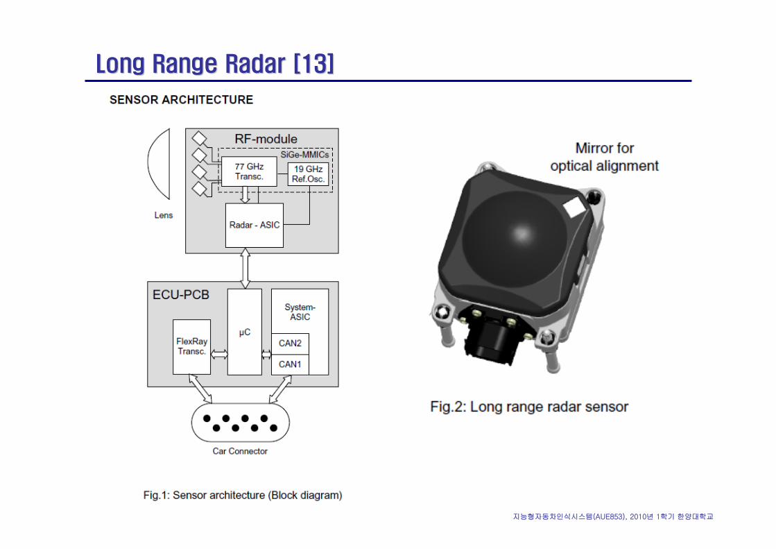
Long Range Radar [13]Long Range Radar [13]
지능형자동차인식시스템(AUE853), 2010년 1학기 한양대학교
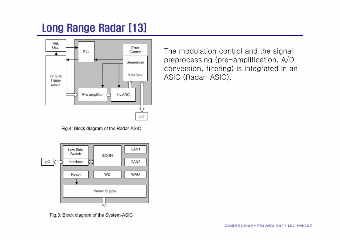
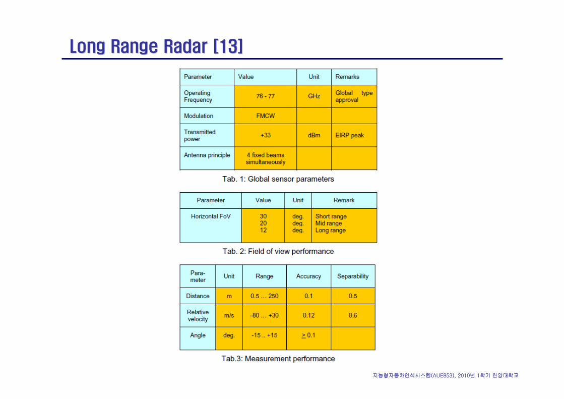
Long Range Radar [13]Long Range Radar [13]
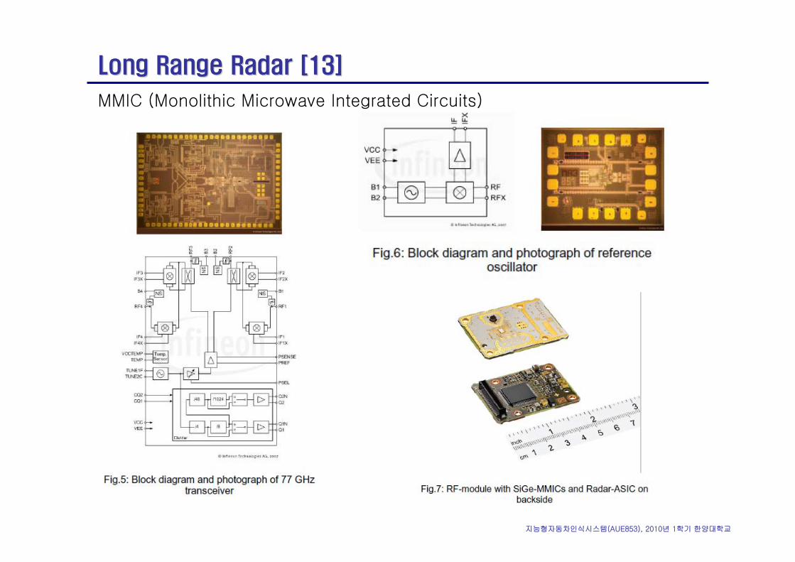
The modulation control and the signal preprocessing (pre-amplification, A/D conversion, filtering) is integrated in an ASIC (Radar-ASIC).
지능형자동차인식시스템(AUE853), 2010년 1학기 한양대학교
Long Range Radar [13]Long Range Radar [13]
MMIC (Monolithic Microwave Integrated Circuits)
지능형자동차인식시스템(AUE853), 2010년 1학기 한양대학교
Long Range Radar [13]Long Range Radar [13]
지능형자동차인식시스템(AUE853), 2010년 1학기 한양대학교
Long Range Radar [13]Long Range Radar [13]
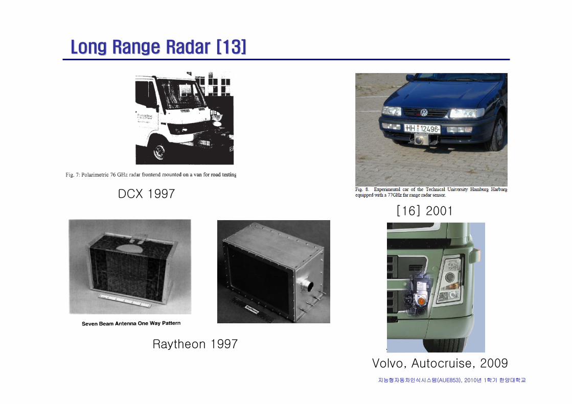
Raytheon 1997
DCX 1997
[16] 2001
Volvo, Autocruise, 2009
지능형자동차인식시스템(AUE853), 2010년 1학기 한양대학교
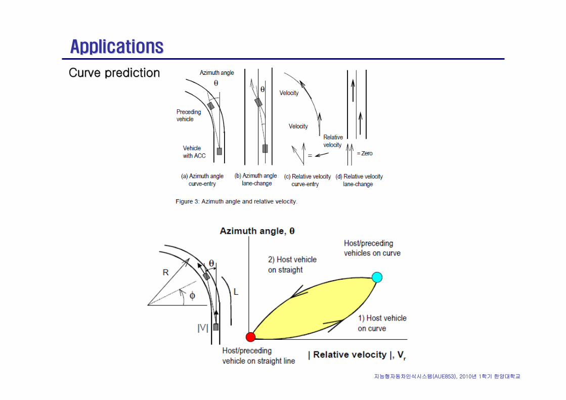
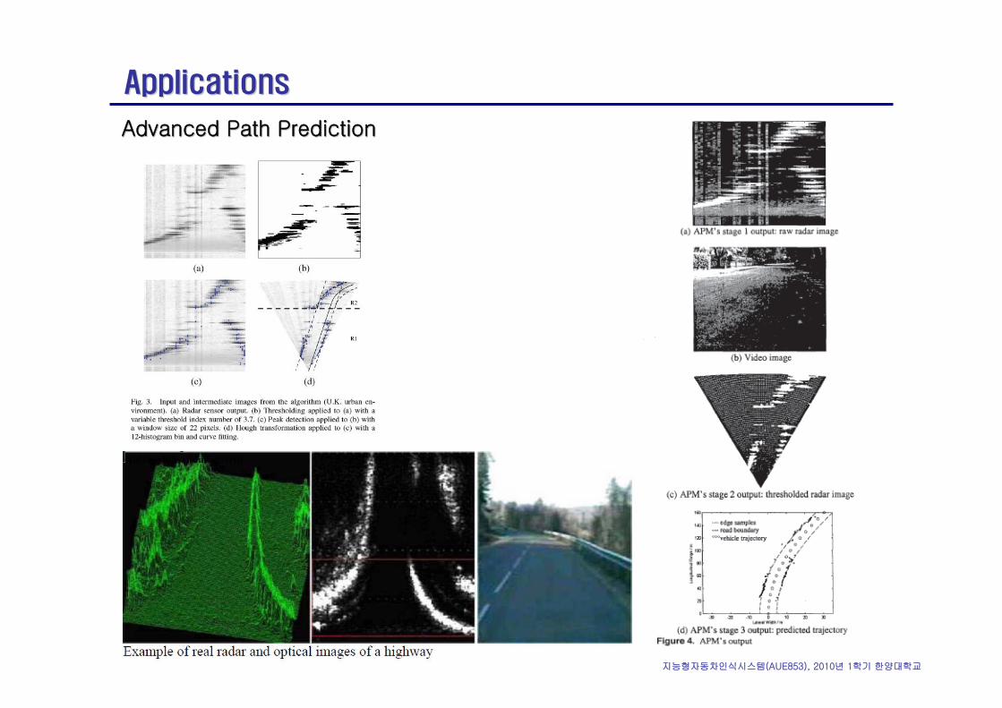
ApplicationsApplications
Curve predictionCurve prediction
지능형자동차인식시스템(AUE853), 2010년 1학기 한양대학교
ApplicationsApplications
Advanced Path PredictionAdvanced Path Prediction
지능형자동차인식시스템(AUE853), 2010년 1학기 한양대학교
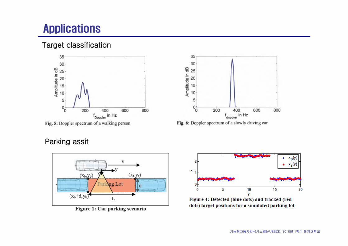
ApplicationsApplications
Target classificationTarget classification
Parking Parking assitassit
지능형자동차인식시스템(AUE853), 2010년 1학기 한양대학교
ReferencesReferences
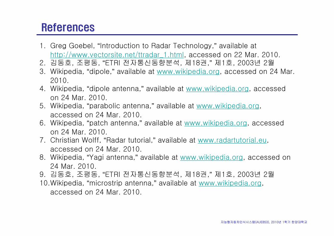
1. Greg Goebel, “Introduction to Radar Technology,” available at
http://www.vectorsite.net/ttradar_1.html, accessed on 22 Mar. 2010.2. 김동호, 조평동, “ETRI 전자통신동향분석, 제18권,” 제1호, 2003년 2월3. Wikipedia, “dipole,” available at www.wikipedia.org, accessed on 24 Mar.
2010.4. Wikipedia, “dipole antenna,” available at www.wikipedia.org, accessed
on 24 Mar. 2010.5. Wikipedia, “parabolic antenna,” available at www.wikipedia.org,
accessed on 24 Mar. 2010.6. Wikipedia, “patch antenna,” available at www.wikipedia.org, accessed
on 24 Mar. 2010.7. Christian Wolff, “Radar tutorial,” available at www.radartutorial.eu,
accessed on 24 Mar. 2010.8. Wikipedia, “Yagi antenna,” available at www.wikipedia.org, accessed on
24 Mar. 2010.9. 김동호, 조평동, “ETRI 전자통신동향분석, 제18권,” 제1호, 2003년 2월10.Wikipedia, “microstrip antenna,” available at www.wikipedia.org,
accessed on 24 Mar. 2010.
지능형자동차인식시스템(AUE853), 2010년 1학기 한양대학교
ReferencesReferences
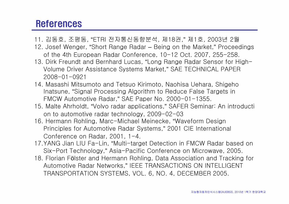
11. 김동호, 조평동, “ETRI 전자통신동향분석, 제18권,” 제1호, 2003년 2월12. Josef Wenger, “Short Range Radar – Being on the Market,” Proceedings
of the 4th European Radar Conference, 10-12 Oct. 2007, 255-258.13. Dirk Freundt and Bernhard Lucas, “Long Range Radar Sensor for High-
Volume Driver Assistance Systems Market,” SAE TECHNICAL PAPER 2008-01-0921
14. Masashi Mitsumoto and Tetsuo Kirimoto, Naohisa Uehara, ShigehoInatsune, “Signal Processing Algorithm to Reduce False Targets in FMCW Automotive Radar,” SAE Paper No. 2000-01-1355.
15. Malte Ahrholdt, “Volvo radar applications,” SAFER Seminar: An introduction to automotive radar technology, 2009-02-03
16. Hermann Rohling, Marc-Michael Meinecke, “Waveform Design Principles for Automotive Radar Systems,” 2001 CIE International
Conference on Radar, 2001, 1-4.17.YANG Jian LIU Fa-Lin, “Multi-target Detection in FMCW Radar based on
Six-Port Technology,” Asia-Pacific Conference on Microwave, 2005.18. Florian Fölster and Hermann Rohling, Data Association and Tracking for
Automotive Radar Networks,” IEEE TRANSACTIONS ON INTELLIGENT
TRANSPORTATION SYSTEMS, VOL. 6, NO. 4, DECEMBER 2005.
지능형자동차인식시스템(AUE853), 2010년 1학기 한양대학교
ReferencesReferences
19. S. Slater, et. al., “RadarNet Final Report,” Deliverable D40, Ver. 0.5, 25
Nov. 2004.20. Koelen, Christian Meinecke, Marc-Michael Teubner, Tobias , “High
resolution DOA automotive radar with four receiving antennae,”International Radar Symposium 2006, 24-26 May 2006, 1-4.
21.Yasuyuki Miyake*, Kazuma Natsume and Koichi Hoshi, “EFFECT OF INCREASING ANGULAR COVERAGE OF AUTOMOTIVE RADAR ,” JSAE Paper Number: 20078488 Oct, 2007 Issued No.3073.

지능형자동차인식시스템(AUE853), 2010년 1학기 한양대학교
레이저레이저 레이더레이더
지능형자동차인식시스템(AUE853), 2010년 1학기 한양대학교
용어용어
LASER: Light Amplification by Stimulated Emission of Radiation
LIDAR: Light Detection And Ranging
LADAR: Laser Detection And Ranging
RADAR: Radio Detection And Ranging
지능형자동차인식시스템(AUE853), 2010년 1학기 한양대학교
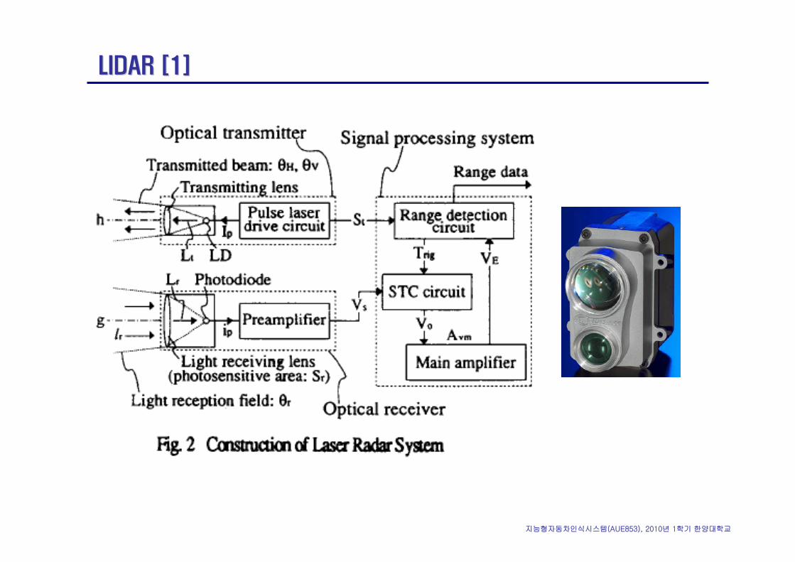
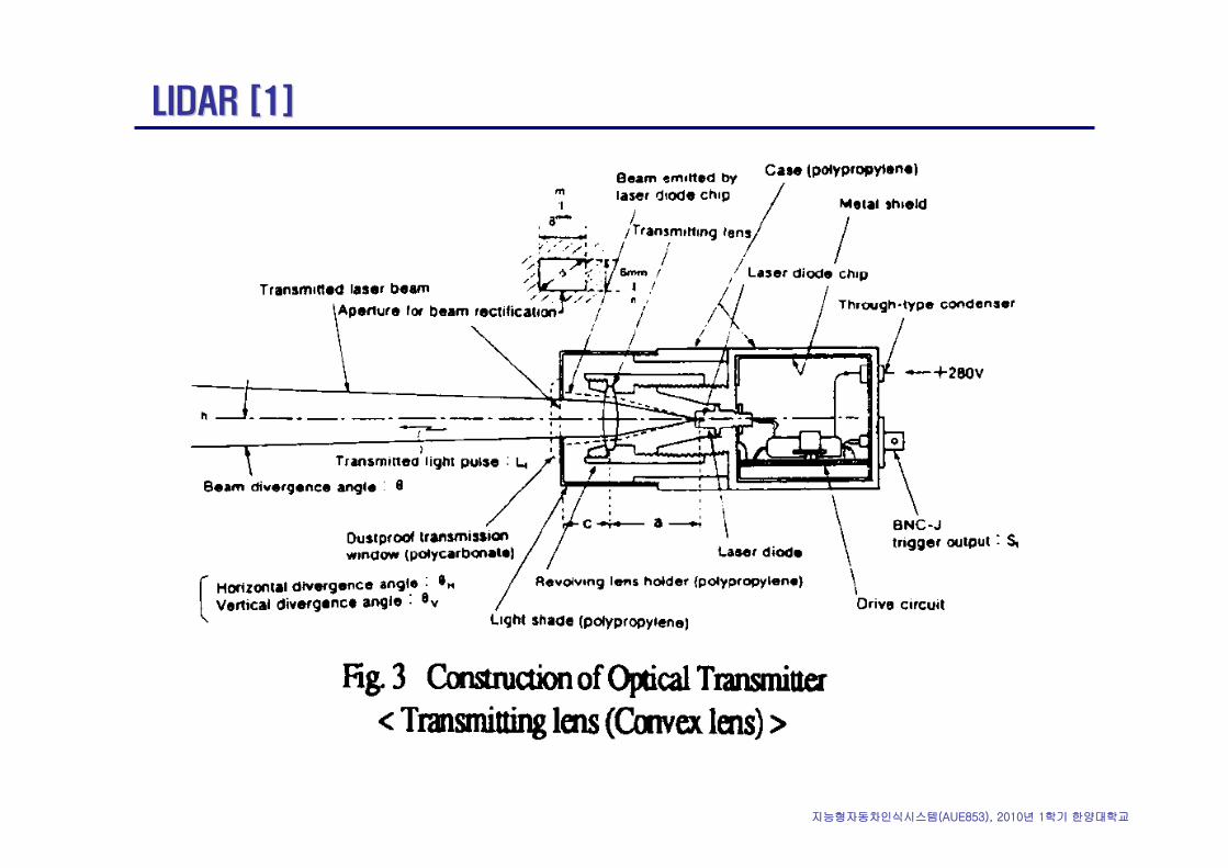
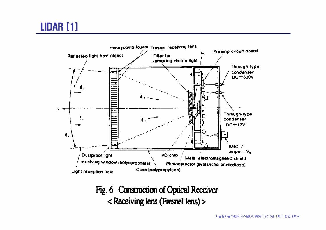
LIDAR [1]LIDAR [1]
지능형자동차인식시스템(AUE853), 2010년 1학기 한양대학교
LIDAR [1]LIDAR [1]
지능형자동차인식시스템(AUE853), 2010년 1학기 한양대학교
LIDAR [1]LIDAR [1]
지능형자동차인식시스템(AUE853), 2010년 1학기 한양대학교
LIDAR [1]LIDAR [1]
APD (avalanche photo diode)
광다이오드에 빛을 입사시켜 역 바이어스 전압을 증가시켜 가면, 발생된 전자가
높은 전계에서 가속되어 원자와 충돌하여 새로운 전자와 정공이 발생하는 눈사
태 현상(avalanche phenomenon)이 생기는데, 이 현상을 이용하여 광신호를
전기 신호로 변환하는 것. 광통신용의 수광 소자로 이용되고 있다. 재료로는 Ge,
Si, Pt-GaAs 등이 사용된다. 특징으로는 다이오드 자신의 눈사태 효과에 의한
전류 증폭 작용으로 신호 대 잡음비(S/N)가 높고, 고속 디지털 회선에 적합하지
만 바이어스 전압이 높으며, 온도 의존성이 크다는 등의 결점이 있다. 광통신의
검출기로는 그 밖에 PIN 다이오드(PD) 등이 사용되고 있다.
지능형자동차인식시스템(AUE853), 2010년 1학기 한양대학교
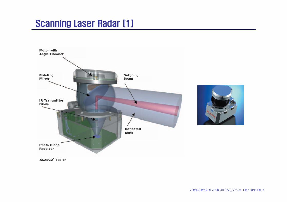
Scanning Laser Radar [1]Scanning Laser Radar [1]
지능형자동차인식시스템(AUE853), 2010년 1학기 한양대학교
Scanning Laser Radar [1]Scanning Laser Radar [1]
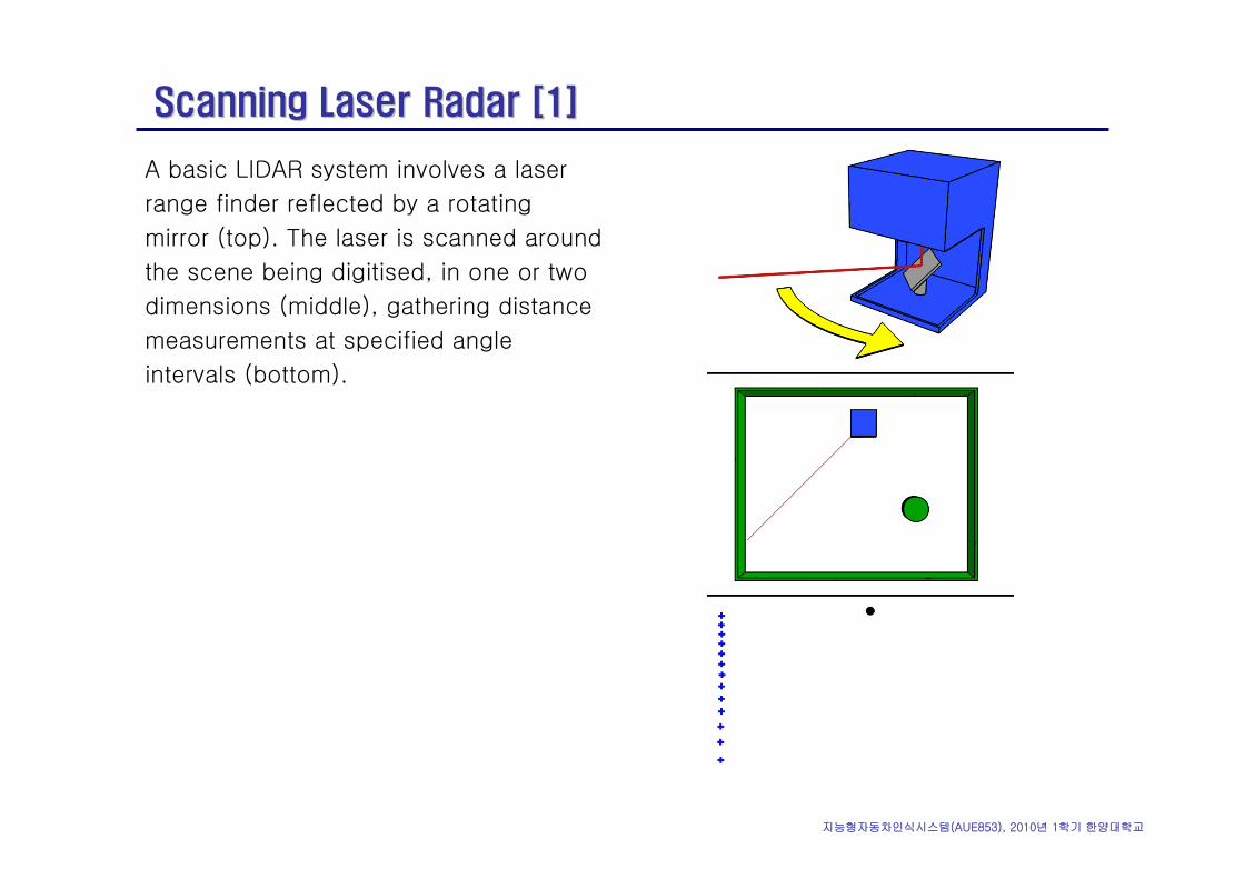
A basic LIDAR system involves a laser
range finder reflected by a rotating
mirror (top). The laser is scanned around
the scene being digitised, in one or two
dimensions (middle), gathering distance
measurements at specified angle
intervals (bottom).
지능형자동차인식시스템(AUE853), 2010년 1학기 한양대학교
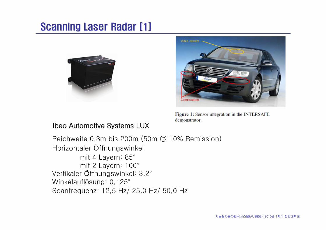
Scanning Laser Radar [1]Scanning Laser Radar [1]
Reichweite 0,3m bis 200m (50m @ 10% Remission)
Horizontaler Öffnungswinkel
mit 4 Layern: 85°mit 2 Layern: 100°
Vertikaler Öffnungswinkel: 3,2°Winkelauflösung: 0,125°
Scanfrequenz: 12,5 Hz/ 25,0 Hz/ 50,0 Hz
IbeoIbeo Automotive Systems LUXAutomotive Systems LUX
지능형자동차인식시스템(AUE853), 2010년 1학기 한양대학교
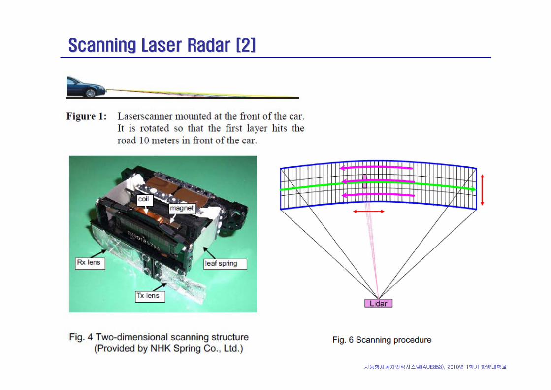
Scanning Laser Radar [2]Scanning Laser Radar [2]
지능형자동차인식시스템(AUE853), 2010년 1학기 한양대학교
ReferencesReferences
1. Sekine, M. Senoo, T. Morita, I. Endo, H., “Design method for an automotive laser radar system and future prospects for laser radar,”Intelligent Vehicle Symposium ’92, 29 Jun. – Jul. 1992, 120-125.
2. Satoru Arita, David Goff, Hidenori Miyazaki and Wataru Ishio, “Wide Field of View (FOV) and High-Resolution Lidar for Advanced Driver Assistance Systems,” SAE Paper No. 2007-01-0406.


![Pressure ur Sensors [圧力センサ] Sensor Applications Micro-Pressure Range Low-Pressure Range High-Pressure Range Gas pressure control, washing machine water level control, filter](https://img.pdfslide.tips/doc/110x75/5b04aa5f7f8b9a4e538e1a10/pressure-ur-sensors-sensor-applications-micro-pressure-range-low-pressure.jpg)


![Folleto técnico Termostatos, termostatos diferenciales RT...Tabla general de los termostatos RT [ C] Range [ C] Type-50 0 50 100 150 200 250 300 Carga de vapor con sensor remoto (sensor](https://img.pdfslide.tips/doc/110x75/60cecc2cbf543c1e250de80b/folleto-tcnico-termostatos-termostatos-diferenciales-rt-tabla-general-de.jpg)