Embed Size (px)
Citation preview
RAPID PROTOTYPING
Brandenburg University of Technology
Cottbus4.-5. February 2010
15/02/2010 SEPPO AARNIO
15/02/2010 S.AARNIO
THREE PHASES OF DEVELOPMENT
LEADING TO RAPID PROTOTYPING
• MANUAL PROTOTYPING
• SOFT or VIRTUAL PROTOTYPING
• RAPID PROTOTYPING (of physical
parts)
”Solid freeform fabrication”, ”Desktop manufacturing” or ”Layer
manufacturing Technology”.
15/02/2010 S.AARNIO
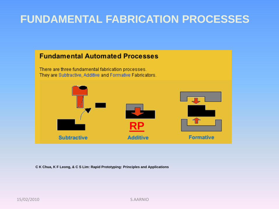
FUNDAMENTAL FABRICATION PROCESSES
C K Chua, K F Leong, & C S Lim: Rapid Prototyping: Principles and Applications
RP
15/02/2010 S.AARNIO
1. OVERVIEW OF RAPID PROTOTYPING
The term rapid prototyping (RP) refers to a class of technologies
that can automatically construct physical models from Computer-
Aided Design (CAD) data.
The main advantage of the system is that almost any shape can be
produced. Time and money savings vary from 50 – 90 % compared
to conventional systems.
Rapid prototyping techniques are often referred to solid free-form
fabrication, computer automated manufacturing or layered
manufacturing.
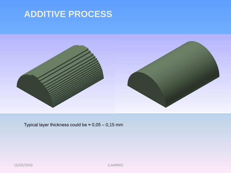
The computer model is sliced into thin layers and the part is
fabricated by adding layers on to of each other.
Since 1988 more than twenty different rapid prototyping techniques have
emerged.
15/02/2010
Typical layer thickness could be ≈ 0,05 – 0,15 mm
S.AARNIO
ADDITIVE PROCESS
15/02/2010 S.AARNIO
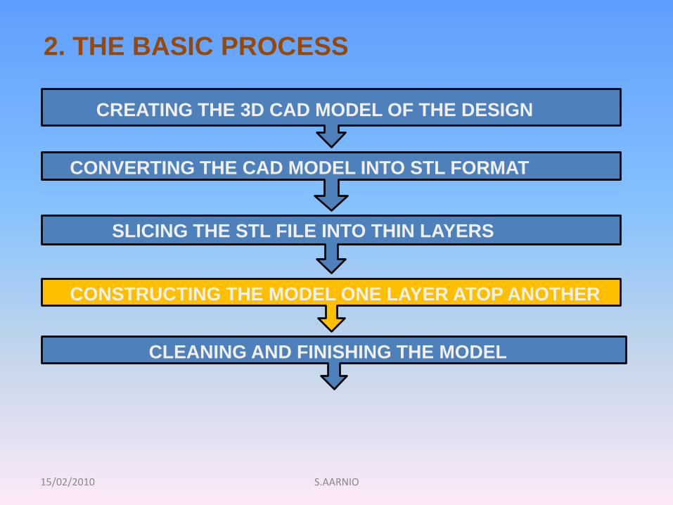
2. THE BASIC PROCESS
CREATING THE 3D CAD MODEL OF THE DESIGN
CONVERTING THE CAD MODEL INTO STL FORMAT
SLICING THE STL FILE INTO THIN LAYERS
CONSTRUCTING THE MODEL ONE LAYER ATOP ANOTHER
CLEANING AND FINISHING THE MODEL
15/02/2010 S.AARNIO
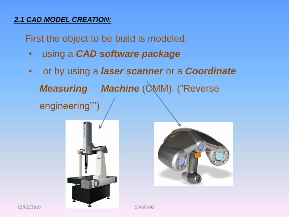
2.1 CAD MODEL CREATION:
First the object to be build is modeled:
• using a CAD software package
• or by using a laser scanner or a Coordinate
Measuring Machine (CMM). (”Reverse
engineering””)
15/02/2010 S.AARNIO
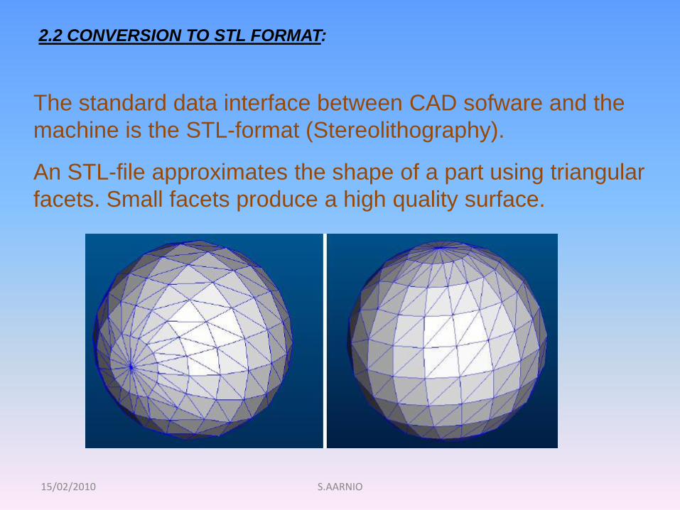
2.2 CONVERSION TO STL FORMAT:
The standard data interface between CAD sofware and the
machine is the STL-format (Stereolithography).
An STL-file approximates the shape of a part using triangular
facets. Small facets produce a high quality surface.
15/02/2010 S.AARNIO
Since the .stl format is universal, this process is identical
for all of the RP build techniques.
3.2 SLICE THE STL FILE:
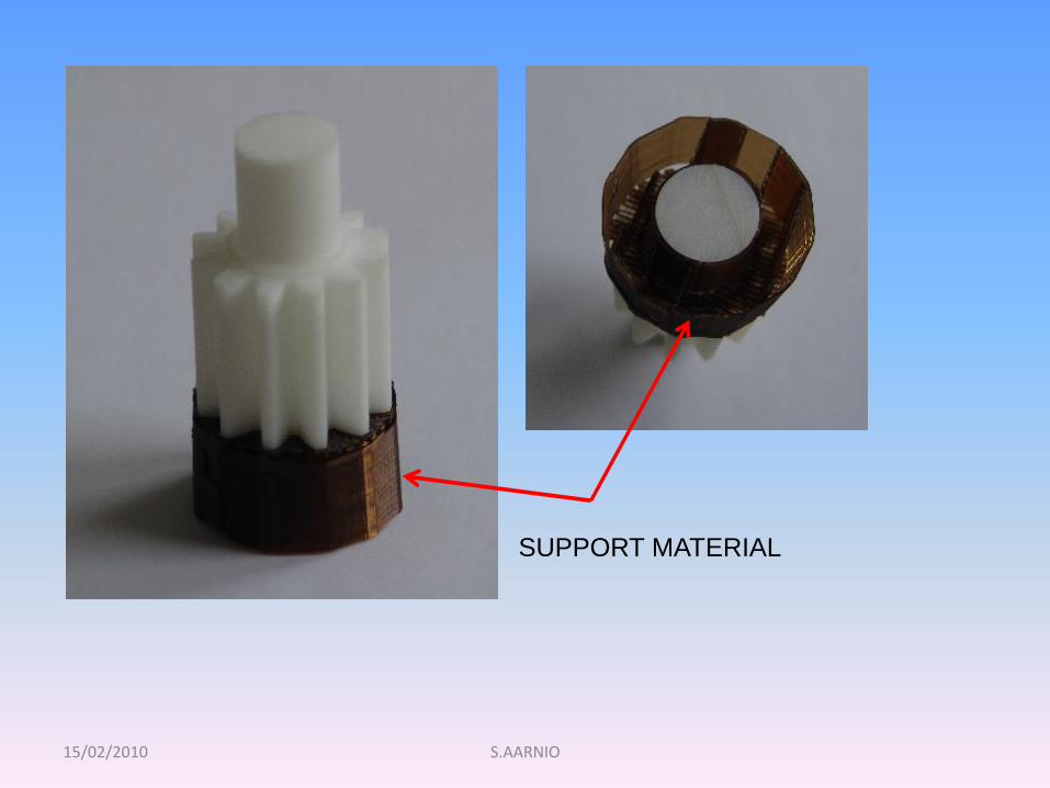
The program may also generate an auxiliary structure to
Support the model during the build
http://www.youtube.com/watch?v=80aXU5q2Kgg
15/02/2010 S.AARNIO
SUPPORT MATERIAL
15/02/2010 S.AARNIO
4.2 LAYER BY LAYER CONSTRUCTION:
The fourth step is the actual construction of the part.
Using one of several techniques (described later) RP
machines build the model layer by layer.
The material´s initial states are:
• LIQUID
• SOLID or
• POWDER
15/02/2010 S.AARNIO
5.2 CLEAN AND FINISH:
• Removement of the part from the machine
• Detaching any supports
• Aftercure (some photosensitive materials)
• Cleaning and surface treatment
• Possible painting etc
15/02/2010 S.AARNIO
• Almost any shape or geometric feature can be produced.
• Reduction in time and cost (could range 50 – 90%. Wohler)
• Errors and flaws can be detected at an early stage.
• RP/RM can be used in different industries and fields of life
(medicine, art and architecture, marketing..)
• Discussions with the customer can start at an early stage.
• Assemblies can be made directly in one go.
• Material waste is reduced.
• No tooling is necessary.
• The designers and the machinery can be in separate places.
•
3. GENERAL ADVANTAGES OF RP
15/02/2010 S.AARNIO
• The price of machinery and materials.
• The surface is usually rougher than machined surfaces.
• Some materials are brittle.
• The strength of RP-parts are weaker in z-direction than in
other.
•
4. SOME DISADVANTAGES OF RP
15/02/2010 S.AARNIO
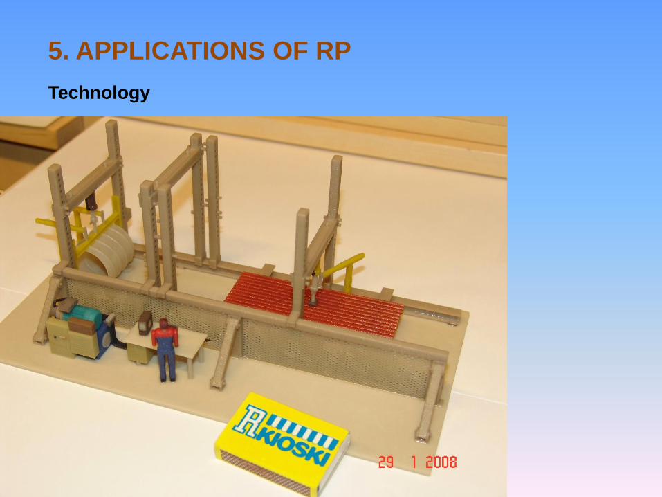
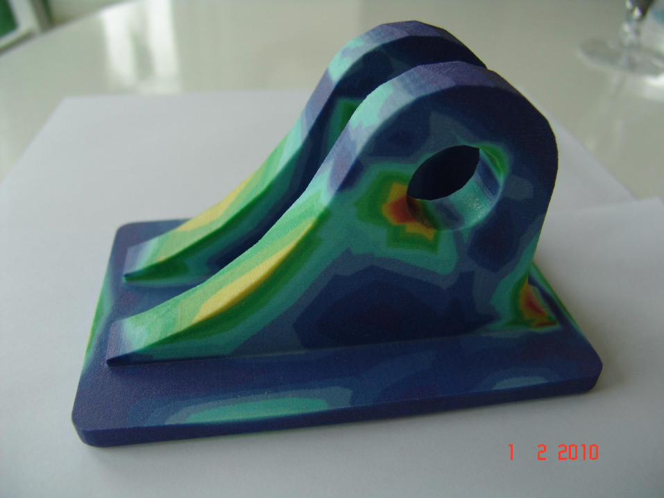
5. APPLICATIONS OF RP
Technology
15/02/2010 S.AARNIO
15/02/2010 S.AARNIO
15/02/2010 S.AARNIO
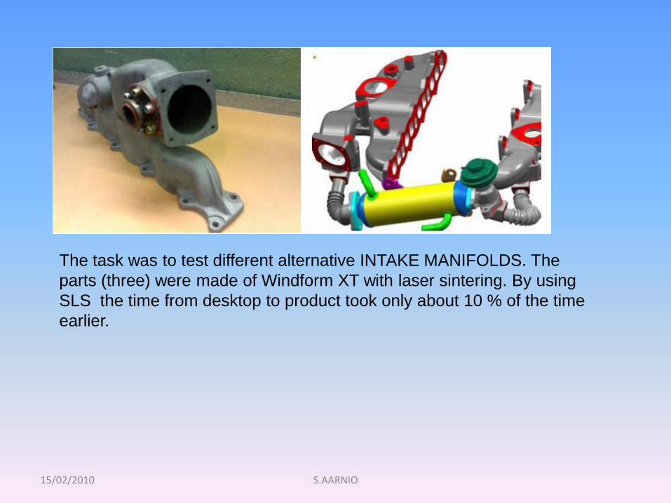
The task was to test different alternative INTAKE MANIFOLDS. The
parts (three) were made of Windform XT with laser sintering. By using
SLS the time from desktop to product took only about 10 % of the time
earlier.
15/02/2010 S.AARNIO
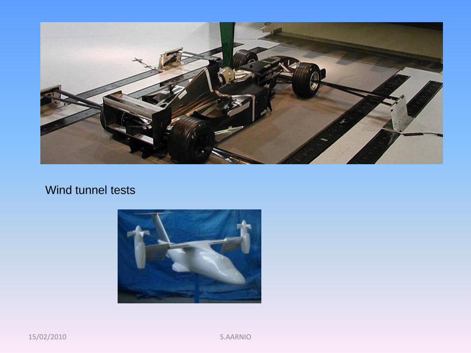
Wind tunnel tests
15/02/2010 S.AARNIO
15/02/2010 S.AARNIO
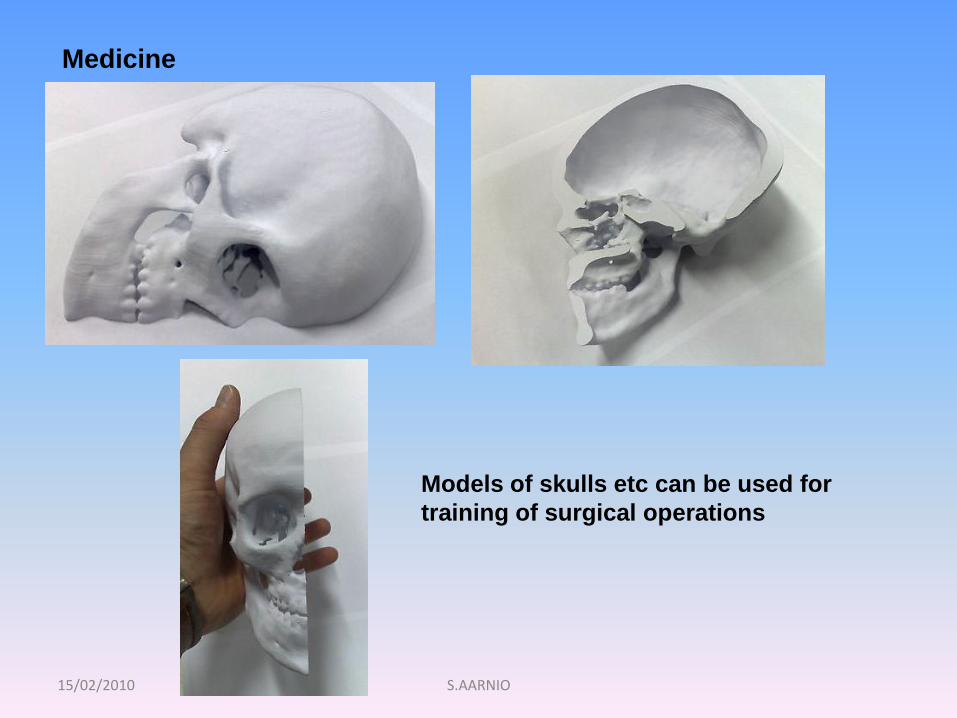
Medicine
Models of skulls etc can be used for
training of surgical operations
15/02/2010 S.AARNIO
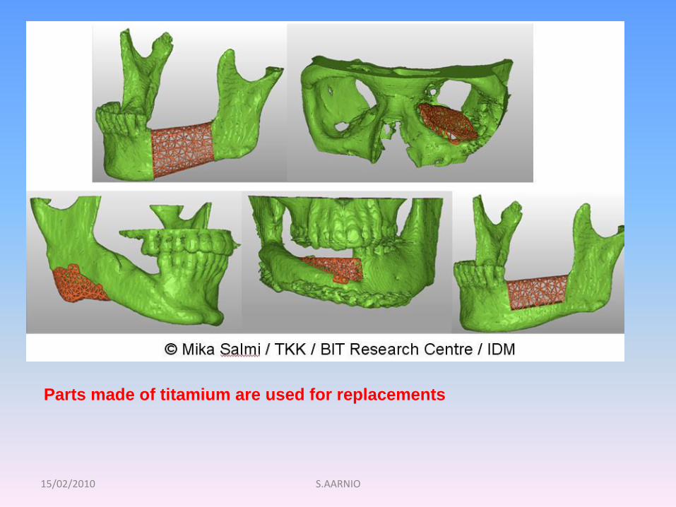
Parts made of titamium are used for replacements
15/02/2010 S.AARNIO
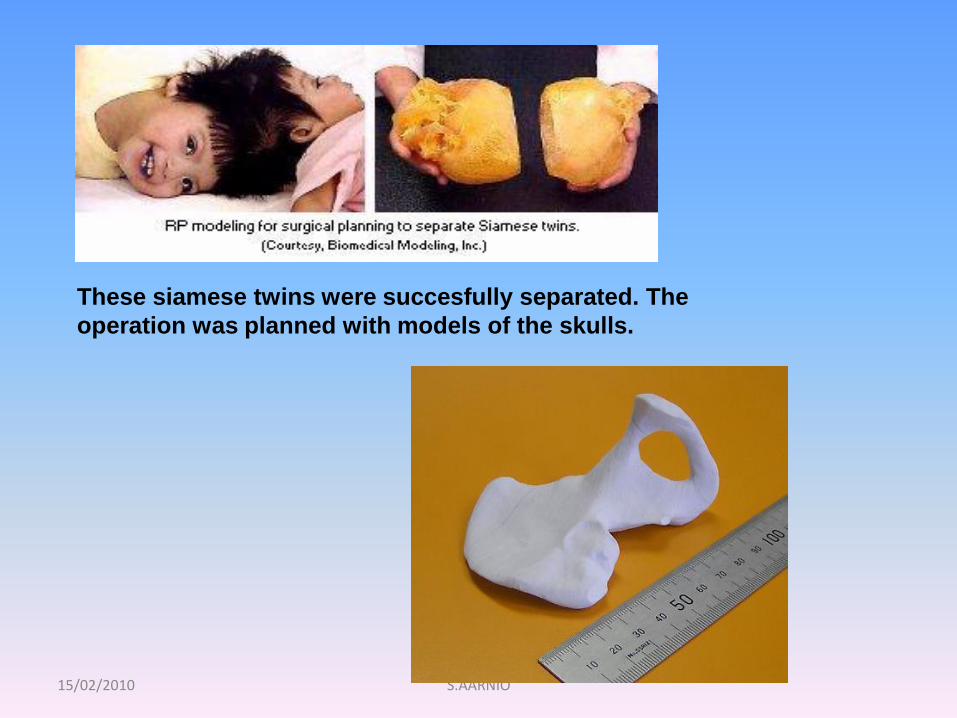
These siamese twins were succesfully separated. The
operation was planned with models of the skulls.
15/02/2010 S.AARNIO
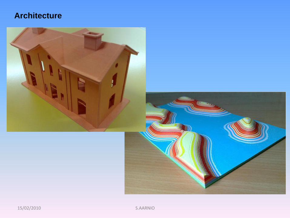
Architecture
15/02/2010 S.AARNIO
6. RP-TECHNOLOGIES
• Stereolithography (SLA)
• Fused Deposition Modeling (FDM)
• Selective Laser Sintering (SLS)
• Laminated Object Manufacturing (LOM)
• 3D Printing
• Direct metal laser sintering (DMLS)
15/02/2010 S.AARNIO
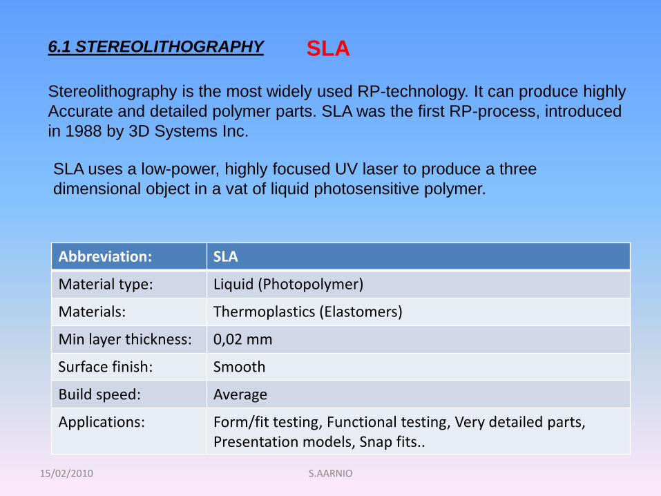
6.1 STEREOLITHOGRAPHY
Stereolithography is the most widely used RP-technology. It can produce highly
Accurate and detailed polymer parts. SLA was the first RP-process, introduced
in 1988 by 3D Systems Inc.
SLA uses a low-power, highly focused UV laser to produce a three
dimensional object in a vat of liquid photosensitive polymer.
Abbreviation: SLA
Material type: Liquid (Photopolymer)
Materials: Thermoplastics (Elastomers)
Min layer thickness: 0,02 mm
Surface finish: Smooth
Build speed: Average
Applications: Form/fit testing, Functional testing, Very detailed parts, Presentation models, Snap fits..
SLA
15/02/2010 S.AARNIO
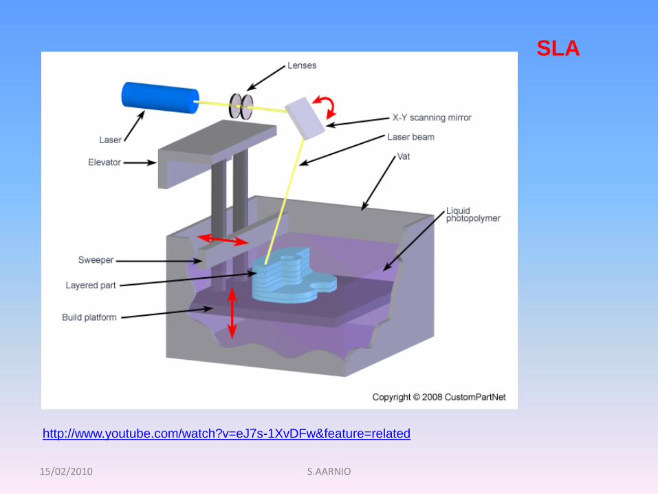
SLA
http://www.youtube.com/watch?v=eJ7s-1XvDFw&feature=related
15/02/2010 S.AARNIO
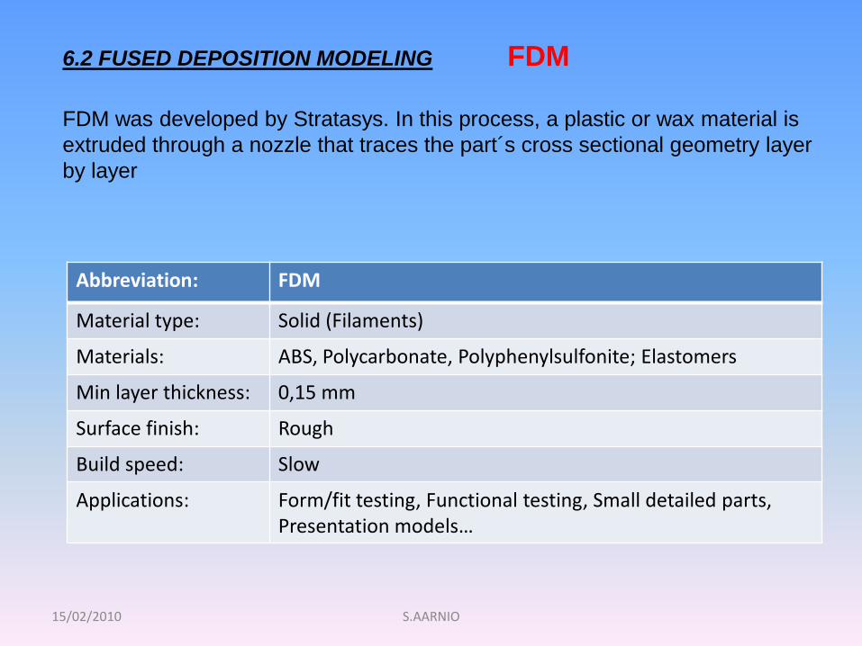
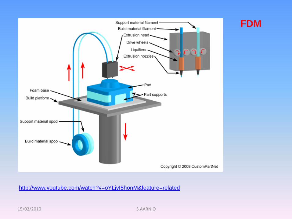
6.2 FUSED DEPOSITION MODELING
FDM was developed by Stratasys. In this process, a plastic or wax material is
extruded through a nozzle that traces the part´s cross sectional geometry layer
by layer
Abbreviation: FDM
Material type: Solid (Filaments)
Materials: ABS, Polycarbonate, Polyphenylsulfonite; Elastomers
Min layer thickness: 0,15 mm
Surface finish: Rough
Build speed: Slow
Applications: Form/fit testing, Functional testing, Small detailed parts, Presentation models…
FDM
15/02/2010 S.AARNIO
FDM
http://www.youtube.com/watch?v=oYLjyI5honM&feature=related
15/02/2010 S.AARNIO
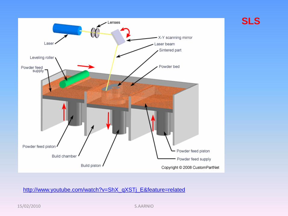
6.3 SELECTIVE LASER SINTERING SLS
SLS was patented in 1989. The basic concept of SLS is similar to that of
SLA. It uses a moving laser beam to trace and selectively sinter powdered
polymer and/or metal composite materials. The powder is kept at elevated
temperature. Unlike SLA, special support structures are not required
because the excess powder in each layer as a support.
With the metal composite material, the SLS process solidifies a polymer
binder material around steel powder (diameter ca. 0.1 mm) one slice at a
time forming the part.
The part is then placed in a furnace (>900 °C), where the polymer binder is
burned off and the part is infiltrated with bronze to improve its density.
SLS allows for a wide range of materials, including nylon, glass-filled nylon,
Truform (investment casting) and metal composites.
15/02/2010 S.AARNIO
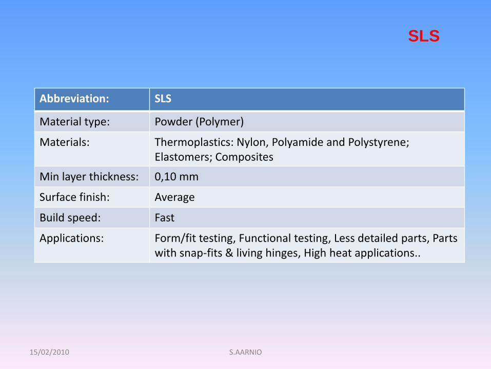
Abbreviation: SLS
Material type: Powder (Polymer)
Materials: Thermoplastics: Nylon, Polyamide and Polystyrene;Elastomers; Composites
Min layer thickness: 0,10 mm
Surface finish: Average
Build speed: Fast
Applications: Form/fit testing, Functional testing, Less detailed parts, Partswith snap-fits & living hinges, High heat applications..
SLS
15/02/2010 S.AARNIO
SLS
http://www.youtube.com/watch?v=ShX_qXSTj_E&feature=related
15/02/2010 S.AARNIO
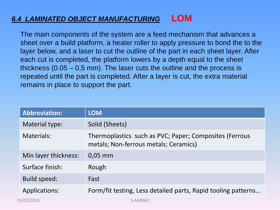
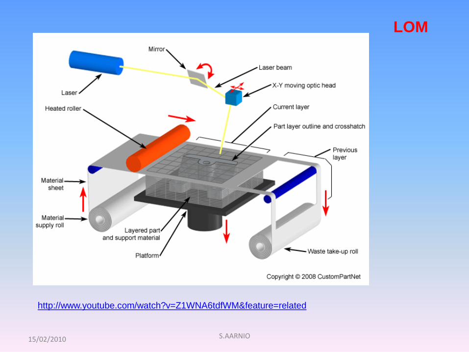
6.4 LAMINATED OBJECT MANUFACTURING
The main components of the system are a feed mechanism that advances a
sheet over a build platform, a heater roller to apply pressure to bond the to the
layer below, and a laser to cut the outline of the part in each sheet layer. After
each cut is completed, the platform lowers by a depth equal to the sheet
thickness (0.05 – 0,5 mm). The laser cuts the outline and the process is
repeated until the part is completed. After a layer is cut, the extra material
remains in place to support the part.
Abbreviation: LOM
Material type: Solid (Sheets)
Materials: Thermoplastics such as PVC; Paper; Composites (Ferrousmetals; Non-ferrous metals; Ceramics)
Min layer thickness: 0,05 mm
Surface finish: Rough
Build speed: Fast
Applications: Form/fit testing, Less detailed parts, Rapid tooling patterns…
LOM
15/02/2010 S.AARNIO
LOM
http://www.youtube.com/watch?v=Z1WNA6tdfWM&feature=related
15/02/2010 S.AARNIO
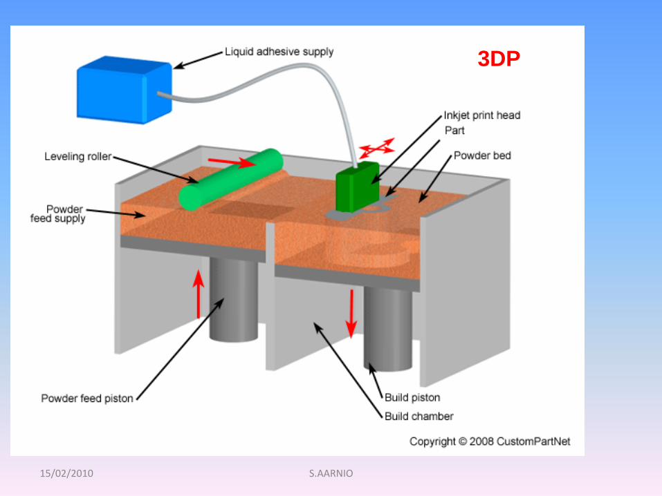
6.4 3D PRINTING
Three Dimensional Printing (3DP) technology was developed at the MIT
and licensed to several corporations. The process is similar to the SLS
process, but instead of using a laser to sinter the material, an ink-jet
printing head deposits a liquid adhesive that binds the material. Material
options are somewhat limited but are inexpensive relative to other
additive processes. 3D printing is quite fast, typically 2 – 4 layers/minute.
However, the accuracy, surface finish, and part strength are not as good
as some other additive processes.
At the end the part is infiltrated with a sealant to improve strength and
surface finish.
3DP
15/02/2010 S.AARNIO
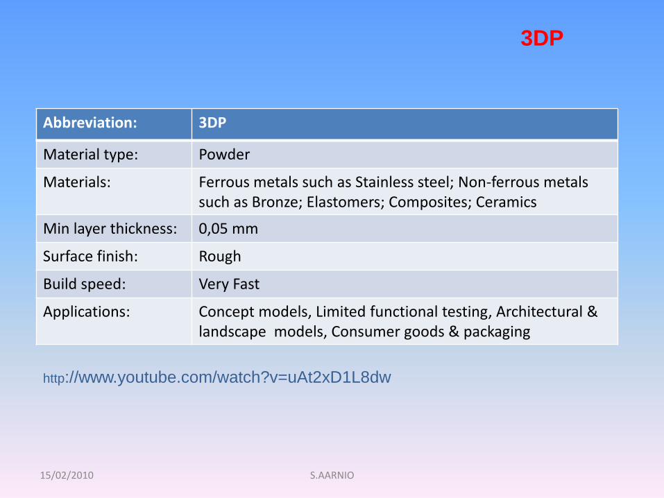
Abbreviation: 3DP
Material type: Powder
Materials: Ferrous metals such as Stainless steel; Non-ferrous metalssuch as Bronze; Elastomers; Composites; Ceramics
Min layer thickness: 0,05 mm
Surface finish: Rough
Build speed: Very Fast
Applications: Concept models, Limited functional testing, Architectural & landscape models, Consumer goods & packaging
3DP
http://www.youtube.com/watch?v=uAt2xD1L8dw
15/02/2010 S.AARNIO
3DP
15/02/2010 S.AARNIO
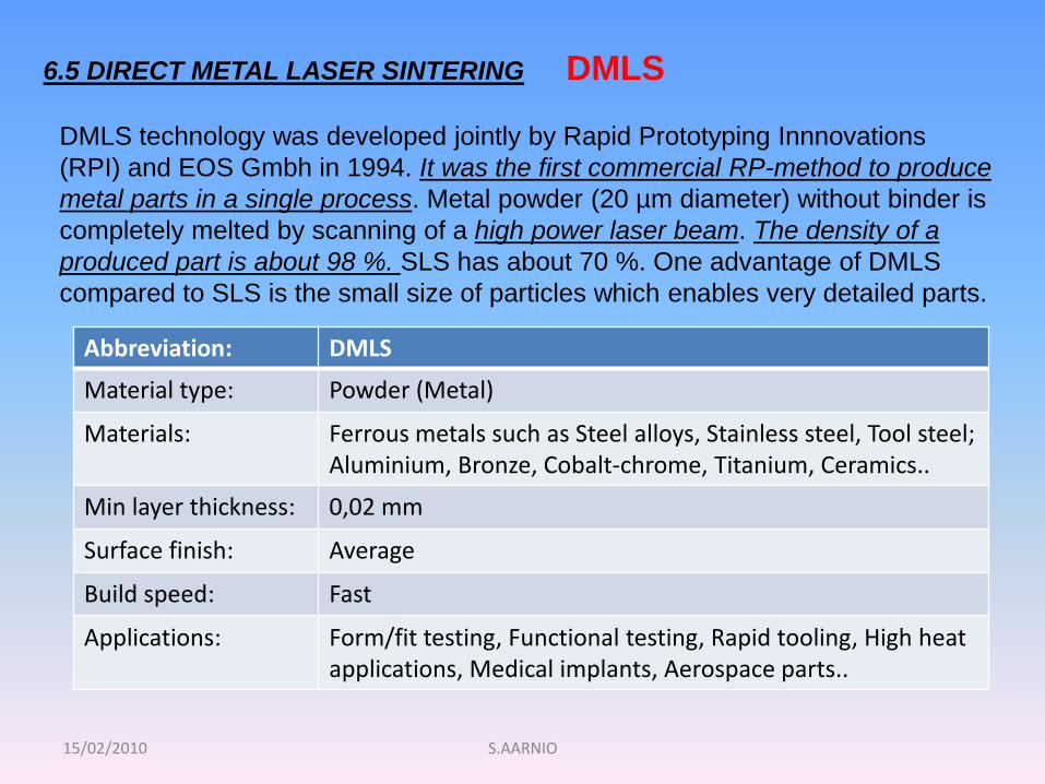
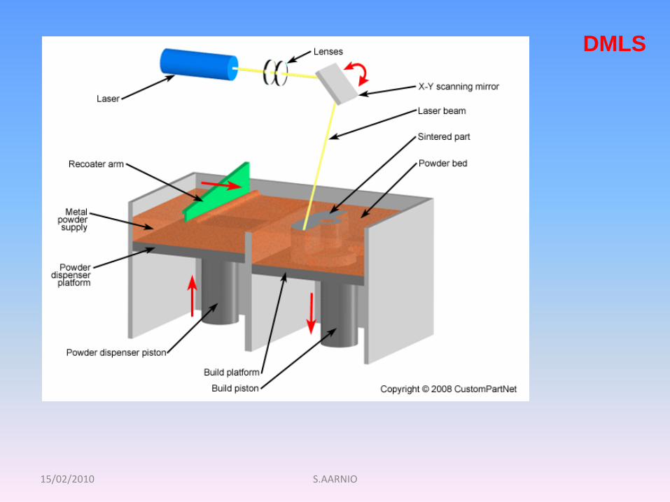
6.5 DIRECT METAL LASER SINTERING
Abbreviation: DMLS
Material type: Powder (Metal)
Materials: Ferrous metals such as Steel alloys, Stainless steel, Tool steel; Aluminium, Bronze, Cobalt-chrome, Titanium, Ceramics..
Min layer thickness: 0,02 mm
Surface finish: Average
Build speed: Fast
Applications: Form/fit testing, Functional testing, Rapid tooling, High heatapplications, Medical implants, Aerospace parts..
DMLS
DMLS technology was developed jointly by Rapid Prototyping Innnovations
(RPI) and EOS Gmbh in 1994. It was the first commercial RP-method to produce
metal parts in a single process. Metal powder (20 µm diameter) without binder is
completely melted by scanning of a high power laser beam. The density of a
produced part is about 98 %. SLS has about 70 %. One advantage of DMLS
compared to SLS is the small size of particles which enables very detailed parts.
15/02/2010 S.AARNIO
DMLS
15/02/2010 S.AARNIO
THANK YOU FOR YOUR
ATTENTION !
HAVE A NICE DAY !