Embed Size (px)
Citation preview

785 Corbett Avenue, San Francisco AISC SMRF Calculations Seismic Retrofit Calculations
Project No. 201813.20 8/22/2018
Page 1 of 77

785 Corbett Avenue, San Francisco AISC SMRF Calculations Seismic Retrofit Calculations
Project No. 201813.20 8/22/2018
Page 2 of 77
785 Corbett Avenue, San Francisco AISC SMRF Calculations Seismic Retrofit Calculations
Project No. 201813.20 8/22/2018
Page 3 of 77

SAP2000
SAP2000 v7.40 - File:SMRF1-PB-GLI - 3-D View - Kip-ft Units
8/21/18 16:23:53 785 Corbett Avenue, San Francisco AISC SMRF Calculations Seismic Retrofit Calculations
Project No. 201813.20 8/22/2018
Page 4 of 77

SAP2000
SAP2000 v7.40 - File:SMRF1-FB-GDI - Joint Loads (EQ) - Kip-ft Units
8/21/18 16:30:09 785 Corbett Avenue, San Francisco AISC SMRF Calculations Seismic Retrofit Calculations
Project No. 201813.20 8/22/2018
Page 5 of 77

SAP2000
SAP2000 v7.40 - File:SMRF1-PB-GLI - Deformed Shape (EQ) - Kip-ft Units
8/21/18 16:26:37 785 Corbett Avenue, San Francisco AISC SMRF Calculations Seismic Retrofit Calculations
Project No. 201813.20 8/22/2018
Page 6 of 77

SAP2000
SAP2000 v7.40 - File:SMRF1-FB-GDI - Deformed Shape (EQ) - Kip-ft Units
8/21/18 16:36:00 785 Corbett Avenue, San Francisco AISC SMRF Calculations Seismic Retrofit Calculations
Project No. 201813.20 8/22/2018
Page 7 of 77

SAP2000
SAP2000 v7.40 - File:SMRF1-FB-GDI - Axial Force Diagram (EQ) - Kip-ft Units
8/21/18 16:37:10 785 Corbett Avenue, San Francisco AISC SMRF Calculations Seismic Retrofit Calculations
Project No. 201813.20 8/22/2018
Page 8 of 77

SAP2000
SAP2000 v7.40 - File:SMRF1-FB-GDI - Shear Force 2-2 Diagram (EQ) - Kip-ft Units
8/21/18 16:37:43 785 Corbett Avenue, San Francisco AISC SMRF Calculations Seismic Retrofit Calculations
Project No. 201813.20 8/22/2018
Page 9 of 77

SAP2000
SAP2000 v7.40 - File:SMRF1-FB-GDI - Moment 3-3 Diagram (EQ) - Kip-ft Units
8/21/18 16:38:06 785 Corbett Avenue, San Francisco AISC SMRF Calculations Seismic Retrofit Calculations
Project No. 201813.20 8/22/2018
Page 10 of 77

SAP2000
SAP2000 v7.40 - File:SMRF1-FB-GDI - Frame Span Loads (WL) - Kip-ft Units
8/21/18 16:31:01 785 Corbett Avenue, San Francisco AISC SMRF Calculations Seismic Retrofit Calculations
Project No. 201813.20 8/22/2018
Page 11 of 77

SAP2000
SAP2000 v7.40 - File:SMRF1-FB-GDI - Frame Span Loads (DL) - Kip-ft Units
8/21/18 16:31:36 785 Corbett Avenue, San Francisco AISC SMRF Calculations Seismic Retrofit Calculations
Project No. 201813.20 8/22/2018
Page 12 of 77

SAP2000
SAP2000 v7.40 - File:SMRF1-FB-GDI - Axial Force Diagram (DDLD) - Kip-ft Units
8/21/18 16:39:00 785 Corbett Avenue, San Francisco AISC SMRF Calculations Seismic Retrofit Calculations
Project No. 201813.20 8/22/2018
Page 13 of 77

SAP2000
SAP2000 v7.40 - File:SMRF1-FB-GDI - Shear Force 2-2 Diagram (DDLD) - Kip-ft Units
8/21/18 16:39:23 785 Corbett Avenue, San Francisco AISC SMRF Calculations Seismic Retrofit Calculations
Project No. 201813.20 8/22/2018
Page 14 of 77

SAP2000
SAP2000 v7.40 - File:SMRF1-FB-GDI - Moment 3-3 Diagram (DDLD) - Kip-ft Units
8/21/18 16:39:46 785 Corbett Avenue, San Francisco AISC SMRF Calculations Seismic Retrofit Calculations
Project No. 201813.20 8/22/2018
Page 15 of 77

SAP2000
SAP2000 v7.40 - File:SMRF1-FB-GDI - Frame Span Loads (LL) - Kip-ft Units
8/21/18 16:33:54 785 Corbett Avenue, San Francisco AISC SMRF Calculations Seismic Retrofit Calculations
Project No. 201813.20 8/22/2018
Page 16 of 77

SAP2000
SAP2000 v7.40 - File:SMRF1-FB-GDI - Axial Force Diagram (LL) - Kip-ft Units
8/21/18 16:40:39 785 Corbett Avenue, San Francisco AISC SMRF Calculations Seismic Retrofit Calculations
Project No. 201813.20 8/22/2018
Page 17 of 77

SAP2000
SAP2000 v7.40 - File:SMRF1-FB-GDI - Shear Force 2-2 Diagram (LL) - Kip-ft Units
8/21/18 16:40:57 785 Corbett Avenue, San Francisco AISC SMRF Calculations Seismic Retrofit Calculations
Project No. 201813.20 8/22/2018
Page 18 of 77

SAP2000
SAP2000 v7.40 - File:SMRF1-FB-GDI - Moment 3-3 Diagram (LL) - Kip-ft Units
8/21/18 16:41:24 785 Corbett Avenue, San Francisco AISC SMRF Calculations Seismic Retrofit Calculations
Project No. 201813.20 8/22/2018
Page 19 of 77

785 Corbett Avenue, San Francisco AISC SMRF Calculations Seismic Retrofit Calculations
Project No. 201813.20 8/22/2018
Page 20 of 77

SPECIAL MOMENT FRAME DESIGN - STORY DRIFT AND STABILITY CHECK
2010 AISC SEISMIC DESIGN MANUAL PROVISIONS - SMRF 1 AT GRIDLINE I - PINNED BASE CONDITION
785 CORBETT AVENUE, SAN FRANCISCO - SEISMIC RETROFIT
Loading Direction : N-S
Floor Level : 1
NS : 3 (Total Number of Stories)
1. Special Moment Frame Data
LRFS is comprised solely of MF's per ASCE 7-10 12.12.1.1 ?: N (Y/N)
New Structure ? : N (Y/N) (Non-structural components designed to accommodate EQ drift?)
Building and floor data Results from Elastic Analysis :
L = 57.00 feet (Building Length) ∆xe = 0.859 inches (Deformation for Level Above at Center of Mass, from elastic analysis)
W = 25.00 feet (Building Width) ∆xe-1 = 0.859 inches ( " for Level Below " )
Ha = 10.00 feet (Height of floor above) Vx = 8 Kips (Story Shear)
Hb = 12.00 feet (Height of floor below)
Seismic Deformation at Floor being evaluated:
Note:
∆xe RBS = (1.0 + ARBS) ∆xe for 2c < = bf / 2 Where c = 1.00 inches (from RBS Beam Design)
Note: 2 c = 2.00 inches bf = 5.81 inches (from moment Frame Beam selection below)
bf / 2 = 2.91 inches
OK
ARBS = % Amplification in Elastic Drift due to RBS
= 4 c / bf x 10 Where c = 1.00 inches (from RBS Beam Design)
bf = 5.81 inches (from moment Frame Beam selection below)
= (1 + 0.069) x 0.859 ARBS = 6.88 % Amplification
∆xe = 0.859 inches (Deformation at Level x at Center of Mass, from elastic analysis)
∆xe RBS = 0.918 inches (Deformation at Level Above at Center of Mass - RBS)
Moment Frame Beams
N = 1 (Number of Identical Frames)
Section: W10x30
n : 1 (number of beams/frame) Seismic Parameters:
A 8.84 in2
R = 8 Modification Response Coefficient (ASCE 7-10 Table 12.2-1)
d 10.50 in Cd = 5.50 Deflection Amplification Factor (ASCE 7-10 Table 12.2-1)
tw 0.30 in ρ = 1.3 Redundancy Factor (ASCE 7-10 Section 12.3.4)
bf 5.81 in
tf 0.51 in Occupancy Category: I (ASCE 7-10 Table 1-5-1: Residential Multi-unit Dwelling)
ry 1.37 in I = 1.0 Importance Factor, Table 11.5-2
K 0.81 in
K1 0.69 in SDC = E Seismic Design Category (ASCE 7-10 Section 11.4)
T 8.88 in SDS = 1.09 g's (Site Design Coefficient - Short Period)
Zx 37 in3
Gravity Loads - Unfactored
Floor Roof
D 30.0 20.0 psf Fy = 50 ksi
L 40.0 20.0 psf
wW = 15 psf (Wall Load)
Reduced-Beam-Section connections are used at frame beam-to-column connections; per AISC 358-10 Section 5.8 Step 1, "..effective elastic drifts may be
calculated by multyplying elastic drifts based on gross beam sections by 1.1 for flange reductions up to 50% of beam flange width".
1 of 3 1. SMF Story Drift, Stability AISC 341- 10 WF SMRF 1 - PB.xls 8/21/2018
785 Corbett Avenue, San Francisco AISC SMRF Calculations Seismic Retrofit Calculations
Project No. 201813.20 8/22/2018
Page 21 of 77

SPECIAL MOMENT FRAME DESIGN - STORY DRIFT AND STABILITY CHECK
2010 AISC SEISMIC DESIGN MANUAL PROVISIONS - SMRF 1 AT GRIDLINE I - PINNED BASE CONDITION
785 CORBETT AVENUE, SAN FRANCISCO - SEISMIC RETROFIT
Loading Direction : N-S
Floor Level : 1
NS : 3 (Total Number of Stories)
2. Check Story Drift
a) Allowable Story Drift (ASCE 7-10 Table 12.12-1)
LRFS is comprised solely of MF's per ASCE 7-10 12.12.1.1 ?: N (Y/N)
∆a = hsx (∆a/hsx) /ρ (SDC D-F for LFRS = 100% MF)
= hsx (∆a/hsx) (All other SDC's)
Where hsx = Hb = 12.00 feet (Story height below level x)
SDC = E Seismic Design Category (ASCE 7-10 Section 11.4)
ρ = 1.3 Redundancy Factor (ASCE 7-10 Section 12.3.4)
∆a/hsx = 0.020 for Floors total : 3
Occupancy Category = I (ASCE 7-10 Table 1-5-1: Residential Multi-unit Dwelling)
= > ∆a = 0.24 feet
= 2.88 inches
b) Resulting Drift at Floor Level x (ASCE 7-10 12.8.6)
Where Cd = 5.50 Deflection Amplification Factor (ASCE Table 12.2-1)
δxe => ∆xe RBS = 0.918 inches (Drift at Level Above at Center of Mass from elastic analysis)
I = 1.0 Importance Factor, Table 11.5-2
∆x = 5.05 inches
NG, > ∆a
3. Check Frame or Stability at Floor Level
a) Portion of Gravity loads at Columns beneath floor level
i) Roof and Floor Areas
Afloor = Aroof = L W Where L = 57.00 feet
W = 25.00 feet
Afloor = Aroof = 1,425 ft2
ii) Roof Loads Dr = Dr Aroof Where Dr = 20.0 psf
Aroof = 1,425 ft2
Dr = 29 kips
Lr = Lr Aroof Where Lr = 20.0 psf
Aroof = 1,425 ft2
Lr = 29 kips
iii) Floor Loads Df = D Afloor Where D = 30.0 psf
Afloor = 1,425 ft2
Dr = 43 kips
Lf = L Afloor Where L = 40.0 psf
Afloor = 1,425 ft2
Lf = 57 kips
iv) Wall Loads Ww = ww 2 (L + W) H Where ww = 15 psf (wall weight)
L = 57.00 feet
Ww = 27 kips W = 25.00 feet
H = (0.5 (Ha + Hb) = 11 feet and Ha = 10.00 feet
Hb = 12.00 feet
v) Story weight on columns PD = Dr + Nfloors (Df + Ww) Where Dr = 29 kips (roof)
Nfloors = 3
PD = 238 kips Df = 43 kips (floor)
Ww = 27 kips (wall)
PL = Lr + Nfloors Lf Where Lr = 29 kips (roof)
Nfloors = 3
PL = 200 kips Lf = 57 kips (floor)
Note: Per ASCE 7-10 Section 12.4.2.3 Note 1, 50% of live loads may be considered for Load Combination 5 for L0 <= 100 psf
Px = PD + 0.5 PL Where PD = 238 kips
PL = 200 kips
Px = 338 kips
NG, Drift is NOT acceptable!
I
C 15)-(12.8
I
C xed
X
xed
X
∆=∆>==
δδ
2 of 3 1. SMF Story Drift, Stability AISC 341- 10 WF SMRF 1 - PB.xls 8/21/2018
785 Corbett Avenue, San Francisco AISC SMRF Calculations Seismic Retrofit Calculations
Project No. 201813.20 8/22/2018
Page 22 of 77

SPECIAL MOMENT FRAME DESIGN - STORY DRIFT AND STABILITY CHECK
2010 AISC SEISMIC DESIGN MANUAL PROVISIONS - SMRF 1 AT GRIDLINE I - PINNED BASE CONDITION
785 CORBETT AVENUE, SAN FRANCISCO - SEISMIC RETROFIT
Loading Direction : N-S
Floor Level : 1
NS : 3 (Total Number of Stories)
b) Check of P - Delta Effects (ASCE 7-10 Section 12.8.7)
θ = Stability Coefficient per EQ 12.8-16
= ( Px ∆xe-1 Ie ) / ( Vx Hsx Cd ) ≤ 0.10 Where Px = 338 kips
∆xe-1 = Seismic Design Story Drift of Level x-1 - RBS
= Cd (1.0 + ARBS) ∆xe-1 / Ie (12.8-15) for Cd = 5.50 Deflection Amplification Factor (ASCE 7-10 Table 12.2-1)
ARBS = 6.88 % Amplification
= 5.50 x (1.069) x 0.859 / 1.0 ∆xe-1 = 0.859 inches ( " for Level Below " )
Ie = 1.0 Importance Factor, Table 11.5-2
∆xe-1 = 5.05 inches
Ie = 1.0 Importance Factor, Table 11.5-2
Vx = 8 kips (Story Shear)
H = 11.00 feet
= 132.00 inches
Cd = 5.50 Deflection Amplification Factor (ASCE 7-10 Table 12.2-1)
θ = 0.287
NG
c) Maximum Value for Stability Coefficient
θMAX = 0.5 / (β Cd) ≤ 0.25 (12.8-17) Where β = Shear DCR for Level x
= 1.0 (Conservative assumption per 12.8.7)
Cd = 5.50 Deflection Amplification Factor (ASCE 7-10 Table 12.2-1)
θMAX = 0.091 Note: θ = 0.287 radians
OK NG
Floor Level is NOT Stable!
3 of 3 1. SMF Story Drift, Stability AISC 341- 10 WF SMRF 1 - PB.xls 8/21/2018
785 Corbett Avenue, San Francisco AISC SMRF Calculations Seismic Retrofit Calculations
Project No. 201813.20 8/22/2018
Page 23 of 77

SPECIAL MOMENT FRAME DESIGN - STORY DRIFT AND STABILITY CHECK
2010 AISC SEISMIC DESIGN MANUAL PROVISIONS - SMRF 1 AT GRIDLINE I - FIXED BASE CONDITION
785 CORBETT AVENUE, SAN FRANCISCO - SEISMIC RETROFIT
Loading Direction : N-S
Floor Level : 1
NS : 3 (Total Number of Stories)
1. Special Moment Frame Data
LRFS is comprised solely of MF's per ASCE 7-10 12.12.1.1 ?: N (Y/N)
New Structure ? : N (Y/N) (Non-structural components designed to accommodate EQ drift?)
Building and floor data Results from Elastic Analysis :
L = 57.00 feet (Building Length) ∆xe = 0.196 inches (Deformation for Level Above at Center of Mass, from elastic analysis)
W = 25.00 feet (Building Width) ∆xe-1 = 0.196 inches ( " for Level Below " )
Ha = 10.00 feet (Height of floor above) Vx = 8 Kips (Story Shear)
Hb = 12.00 feet (Height of floor below)
Seismic Deformation at Floor being evaluated:
Note:
∆xe RBS = (1.0 + ARBS) ∆xe for 2c < = bf / 2 Where c = 1.00 inches (from RBS Beam Design)
Note: 2 c = 2.00 inches bf = 5.81 inches (from moment Frame Beam selection below)
bf / 2 = 2.91 inches
OK
ARBS = % Amplification in Elastic Drift due to RBS
= 4 c / bf x 10 Where c = 1.00 inches (from RBS Beam Design)
bf = 5.81 inches (from moment Frame Beam selection below)
= (1 + 0.069) x 0.196 ARBS = 6.88 % Amplification
∆xe = 0.196 inches (Deformation at Level x at Center of Mass, from elastic analysis)
∆xe RBS = 0.210 inches (Deformation at Level Above at Center of Mass - RBS)
Moment Frame Beams
N = 1 (Number of Identical Frames)
Section: W10x30
n : 1 (number of beams/frame) Seismic Parameters:
A 8.84 in2
R = 8 Modification Response Coefficient (ASCE 7-10 Table 12.2-1)
d 10.50 in Cd = 5.50 Deflection Amplification Factor (ASCE 7-10 Table 12.2-1)
tw 0.30 in ρ = 1.3 Redundancy Factor (ASCE 7-10 Section 12.3.4)
bf 5.81 in
tf 0.51 in Occupancy Category: I (ASCE 7-10 Table 1-5-1: Residential Multi-unit Dwelling)
ry 1.37 in I = 1.0 Importance Factor, Table 11.5-2
K 0.81 in
K1 0.69 in SDC = E Seismic Design Category (ASCE 7-10 Section 11.4)
T 8.88 in SDS = 1.09 g's (Site Design Coefficient - Short Period)
Zx 37 in3
Gravity Loads - Unfactored
Floor Roof
D 30.0 20.0 psf Fy = 50 ksi
L 40.0 20.0 psf
wW = 15 psf (Wall Load)
Reduced-Beam-Section connections are used at frame beam-to-column connections; per AISC 358-10 Section 5.8 Step 1, "..effective elastic drifts may be
calculated by multyplying elastic drifts based on gross beam sections by 1.1 for flange reductions up to 50% of beam flange width".
1 of 3 1. SMF Story Drift, Stability AISC 341- 10 WF SMRF 1 - FB.xls 8/21/2018
785 Corbett Avenue, San Francisco AISC SMRF Calculations Seismic Retrofit Calculations
Project No. 201813.20 8/22/2018
Page 24 of 77

SPECIAL MOMENT FRAME DESIGN - STORY DRIFT AND STABILITY CHECK
2010 AISC SEISMIC DESIGN MANUAL PROVISIONS - SMRF 1 AT GRIDLINE I - FIXED BASE CONDITION
785 CORBETT AVENUE, SAN FRANCISCO - SEISMIC RETROFIT
Loading Direction : N-S
Floor Level : 1
NS : 3 (Total Number of Stories)
2. Check Story Drift
a) Allowable Story Drift (ASCE 7-10 Table 12.12-1)
LRFS is comprised solely of MF's per ASCE 7-10 12.12.1.1 ?: N (Y/N)
∆a = hsx (∆a/hsx) /ρ (SDC D-F for LFRS = 100% MF)
= hsx (∆a/hsx) (All other SDC's)
Where hsx = Hb = 12.00 feet (Story height below level x)
SDC = E Seismic Design Category (ASCE 7-10 Section 11.4)
ρ = 1.3 Redundancy Factor (ASCE 7-10 Section 12.3.4)
∆a/hsx = 0.020 for Floors total : 3
Occupancy Category = I (ASCE 7-10 Table 1-5-1: Residential Multi-unit Dwelling)
= > ∆a = 0.24 feet
= 2.88 inches
b) Resulting Drift at Floor Level x (ASCE 7-10 12.8.6)
Where Cd = 5.50 Deflection Amplification Factor (ASCE Table 12.2-1)
δxe => ∆xe RBS = 0.210 inches (Drift at Level Above at Center of Mass from elastic analysis)
I = 1.0 Importance Factor, Table 11.5-2
∆x = 1.15 inches
OK, < ∆a
3. Check Frame or Stability at Floor Level
a) Portion of Gravity loads at Columns beneath floor level
i) Roof and Floor Areas
Afloor = Aroof = L W Where L = 57.00 feet
W = 25.00 feet
Afloor = Aroof = 1,425 ft2
ii) Roof Loads Dr = Dr Aroof Where Dr = 20.0 psf
Aroof = 1,425 ft2
Dr = 29 kips
Lr = Lr Aroof Where Lr = 20.0 psf
Aroof = 1,425 ft2
Lr = 29 kips
iii) Floor Loads Df = D Afloor Where D = 30.0 psf
Afloor = 1,425 ft2
Dr = 43 kips
Lf = L Afloor Where L = 40.0 psf
Afloor = 1,425 ft2
Lf = 57 kips
iv) Wall Loads Ww = ww 2 (L + W) H Where ww = 15 psf (wall weight)
L = 57.00 feet
Ww = 27 kips W = 25.00 feet
H = (0.5 (Ha + Hb) = 11 feet and Ha = 10.00 feet
Hb = 12.00 feet
v) Story weight on columns PD = Dr + Nfloors (Df + Ww) Where Dr = 29 kips (roof)
Nfloors = 3
PD = 238 kips Df = 43 kips (floor)
Ww = 27 kips (wall)
PL = Lr + Nfloors Lf Where Lr = 29 kips (roof)
Nfloors = 3
PL = 200 kips Lf = 57 kips (floor)
Note: Per ASCE 7-10 Section 12.4.2.3 Note 1, 50% of live loads may be considered for Load Combination 5 for L0 <= 100 psf
Px = PD + 0.5 PL Where PD = 238 kips
PL = 200 kips
Px = 338 kips
Resulting Drift is acceptable
I
C 15)-(12.8
I
C xed
X
xed
X
∆=∆>==
δδ
2 of 3 1. SMF Story Drift, Stability AISC 341- 10 WF SMRF 1 - FB.xls 8/21/2018
785 Corbett Avenue, San Francisco AISC SMRF Calculations Seismic Retrofit Calculations
Project No. 201813.20 8/22/2018
Page 25 of 77

SPECIAL MOMENT FRAME DESIGN - STORY DRIFT AND STABILITY CHECK
2010 AISC SEISMIC DESIGN MANUAL PROVISIONS - SMRF 1 AT GRIDLINE I - FIXED BASE CONDITION
785 CORBETT AVENUE, SAN FRANCISCO - SEISMIC RETROFIT
Loading Direction : N-S
Floor Level : 1
NS : 3 (Total Number of Stories)
b) Check of P - Delta Effects (ASCE 7-10 Section 12.8.7)
θ = Stability Coefficient per EQ 12.8-16
= ( Px ∆xe-1 Ie ) / ( Vx Hsx Cd ) ≤ 0.10 Where Px = 338 kips
∆xe-1 = Seismic Design Story Drift of Level x-1 - RBS
= Cd (1.0 + ARBS) ∆xe-1 / Ie (12.8-15) for Cd = 5.50 Deflection Amplification Factor (ASCE 7-10 Table 12.2-1)
ARBS = 6.88 % Amplification
= 5.50 x (1.069) x 0.196 / 1.0 ∆xe-1 = 0.196 inches ( " for Level Below " )
Ie = 1.0 Importance Factor, Table 11.5-2
∆xe-1 = 1.15 inches
Ie = 1.0 Importance Factor, Table 11.5-2
Vx = 8 kips (Story Shear)
H = 11.00 feet
= 132.00 inches
Cd = 5.50 Deflection Amplification Factor (ASCE 7-10 Table 12.2-1)
θ = 0.066
OK
c) Maximum Value for Stability Coefficient
θMAX = 0.5 / (β Cd) ≤ 0.25 (12.8-17) Where β = Shear DCR for Level x
= 1.0 (Conservative assumption per 12.8.7)
Cd = 5.50 Deflection Amplification Factor (ASCE 7-10 Table 12.2-1)
θMAX = 0.091 Note: θ = 0.066 radians
OK OK
Level 1 is considered stable
3 of 3 1. SMF Story Drift, Stability AISC 341- 10 WF SMRF 1 - FB.xls 8/21/2018
785 Corbett Avenue, San Francisco AISC SMRF Calculations Seismic Retrofit Calculations
Project No. 201813.20 8/22/2018
Page 26 of 77

785 Corbett Avenue, San Francisco AISC SMRF Calculations Seismic Retrofit Calculations
Project No. 201813.20 8/22/2018
Page 27 of 77

SPECIAL MOMENT FRAME DESIGN - SMF REDUCED BEAM SECTION BEAM DESIGN
2010 AISC SEISMIC DESIGN MANUAL PROVISIONS - SMRF 1 AT GRIDLINE I - FIXED BASE CONDITION
785 CORBETT AVENUE, SAN FRANCISCO - SEISMIC RETROFIT
Loading Direction : N-S Beam ID: BM-1
Floor Level : 2 Gridline: 10
1. Member Selection and Moment Frame Column Geometry
Girder Data:
S = 14.00 feet (Girder Span)
Ltrib = 4.00 feet ( " Tributary Width - for beam bracing)
SMF Members
Column Left RightBeam
Bracing
W8x67 W10x30 L4x4x3/8
A 19.70 8.84 2.86 in2
d 9.00 10.50 - in
tw 0.57 0.30 - in
bf 8.28 5.81 4.00 in
tf 0.94 0.51 0.38 in
rx 3.72 4.38 1.23 in
ry 2.12 1.37 1.23 in
K 1.33 0.81 - in
K1 0.94 0.69 - in
T 5.75 8.25 - in
Zx 70 37 - in3
Ix 272 170 - in4
RBS Beam Designed: x
Note:
Material Properties (Seismic Design Manual as referenced)
E = 29,000 ksi
BeamsAngle
Bracing
TypeA572, Gr.
50A36
Fy (ksi) 50 36 (Fy min specified, AISC 360-10 Table 2-4, pg 2-48)
Fu (ksi) 65 (Fu stress specified, AISC 360-10 Table 2-4, pg 2-48)
Ry 1.10 (Ratio of Expected Fy to min Fy specified; AISC 341-10 Table A3.1)
Rt 1.10 (Ratio of Expected Fu to min Fu specified; AISC 341-10 Table A3.1)
Reduced Beam Section Geometry AISC 358-10 Section 5.3.1 - Beam Limitations :
Limit Member
d = 36.00 10.5 inches (Beam Depth)
3.50 3.50 Weight = 300 30 Plf (Beam weight)
OK tf = 1.75 0.94 inches (Flange thickness)
7.50 7.50 Span-Depth Ratio = 7.0 15.1
OK
1.00 1.00 Note: W10x30 Beam OK
OK
Where R = (b2/4 + c
2) / 2c
Left Beam Right Beam
ParameterLower
(inches)
Upper
(inches)
Lower
(inches)
Upper
(inches)
a 2.91 4.36 (AISC 358-10 Eq. 5.8-1)
b 6.83 8.93 (AISC 358-10 Eq. 5.8-2)
c 0.58 1.45 (AISC 358-10 Eq. 5.8-3)
3.63125
2. Member and System Demands 7.875
Girder Demands - Unfactored 1.01675 Seismic Parameters:
Dead Live Snow EQ Ωο = 3.0 Overstrength Factor (ASCE Table 12.2-1)
V 7.0 0.5 3.0 Kips ρ = 1.30 Redundancy Factor (ASCE Section 12.3.4)
M 12.0 1.0 20.0 Kip-ft
SDC = E Seismic Design Category (ASCE 7-05 Section 11.4)
SDS = 1.091 g's (Site Design Coefficient - Short Period)
R
(inches)7.53
Both girders shown (if selected), only one checked;
default is Left girder.
a
(inches)
b
(inches)
c
(inches)
Left BeamParameter
Girders
0.50 bbf ≤ a ≤ 0.75 bbf
0.65 d ≤ b ≤ 0.85 d
0.10 bbf ≤ c ≤ 0.25 bbf
Limits
Reduced Beam Section Limits (AISC 358-10 Section 5.8)
Right
Beam
RBS Beam-Column Connection
-25
-20
-15
-10
-5
0
5
10
15
20
25
0 5 10 15 20 25 30 35
1 of 6 3. SMF RBS Beam Design AISC 341- 10 WF SMRF 1 - FB.xls 8/22/2018
785 Corbett Avenue, San Francisco AISC SMRF Calculations Seismic Retrofit Calculations
Project No. 201813.20 8/22/2018
Page 28 of 77

SPECIAL MOMENT FRAME DESIGN - SMF REDUCED BEAM SECTION BEAM DESIGN
2010 AISC SEISMIC DESIGN MANUAL PROVISIONS - SMRF 1 AT GRIDLINE I - FIXED BASE CONDITION
785 CORBETT AVENUE, SAN FRANCISCO - SEISMIC RETROFIT
Loading Direction : N-S Beam ID: BM-1
Floor Level : 2 Gridline: 10
3. Factored Loads
Note: Factored Loads - Basic Combinations for Strength Design (ASCE 7-05 Section 12.4.2.3)
i) Shear Force Demands
Vu = (1.2 + 0.2 SDS) VD + ρ VEQ + 0.5 VL + 0.2 VS Where VD = 7.0 Kips (Dead Load) and ρ = 1.3 Redundancy Factor (ASCE Section 12.3.4)
VL = 0.5 Kips (Live Load)* SDS = 1.091 g's (Site Design Coefficient - Short Period)
Vs = 0.0 Kips (Snow Load)
VE = 3.0 Kips
Vu = 14.1 kips
ii) Flexural Demands
Mu = (1.2 + 0.2 SDS) MD + ρ MEQ + 0.5 ML + 0.2 MS Where MD = 12.0 Kip-ft (Dead Load) and ρ = 1.3 Redundancy Factor (ASCE Section 12.3.4)
ML = 1.0 Kip-ft (Live Load)* SDS = 1.091 g's (Site Design Coefficient - Short Period)
Ms = 0.0 Kip-ft (Snow Load)
MEQ = Mu = 20 Kip-ft
Mu = 44 kip-ft
4. Seismic b/t Ratio Check (AISC 341-10 Table D1.1) - Left Girder Quick Check:
at Flanges (Table D1.1):
and bf,RBS = bf - c for bf = 5.81 inches
c = 1.00 inches
bf,RBS = 4.81 inches
tf = 0.51 inches Note: Neglecting RBS cut, thus c = 0.0, is more conservative.
λf = 4.72
Where E = 29,000 Ksi
Fy = 50 Ksi (Fy min specified, AISC 360-10 Table 2-3, pg 2-40)
λhd = 7.22
OK, Flanges satisfy Seismic b/t Ratio
at Web (Table D1.1):
and h = T = 8.25 inches (from AISC Manual Table 1-1)
tw = 0.30 inches ( " )
λw = 27.50
Note: No Axial load in beam, therefore Ca = 0, and λhd as follows:
Where E = 29,000 Ksi
Fy = 50 Ksi (Fy min specified, AISC 360-10 Table 2-3, pg 2-40)
λhd = 59.00
OK, Web satisfies Seismic b/t Ratio
Use AISC 341-10 Table 1-3 for SMF
sections that satisfy Seismic b/t
requirements.
WF Section satisfies Seismic b/t Ratio for Highly Ductile Beam
w
wt
h=λ
f
f
ft
b
2=λ
F
E 0.30 λ
y
hd =
y
hdF
E45.2=λ
2 of 6 3. SMF RBS Beam Design AISC 341- 10 WF SMRF 1 - FB.xls 8/22/2018
785 Corbett Avenue, San Francisco AISC SMRF Calculations Seismic Retrofit Calculations
Project No. 201813.20 8/22/2018
Page 29 of 77

SPECIAL MOMENT FRAME DESIGN - SMF REDUCED BEAM SECTION BEAM DESIGN
2010 AISC SEISMIC DESIGN MANUAL PROVISIONS - SMRF 1 AT GRIDLINE I - FIXED BASE CONDITION
785 CORBETT AVENUE, SAN FRANCISCO - SEISMIC RETROFIT
Loading Direction : N-S Beam ID: BM-1
Floor Level : 2 Gridline: 10
5. Flexural Strength (AISC 360-10 Section F2) - Left Girder Quick Check:
a) Unbraced length limits for Flexural members - Limit state of yielding - Gross Section
Where ry = 1.37 inches
E = 29,000 Ksi
Fy = 50 Ksi
Lp = 58.1 inches
= 4.84 feet
b) Unbraced length limits for Flexural members - Limit state of Lateral Torsional Buckling - Gross Section
Note: rts provided on AISC Table 1-1, Lr provided on AISC Table 3-6 for WF shapes, but not provided in Spreadsheet database and therefore calculated here.
and bf = 5.81 inches (from AISC Manual Table 1-1)
h = T = 8.25 inches (from AISC Manual Table 1-1)
tw = 0.30 inches
tf = 0.51 inches
rts = 1.57 inches No
Where rts = 1.57 inches
E = 29,000 Ksi
Fy = 50 Ksi
J = 0.622 in4 (Table 1-1)
Lr = 190.0 inches c = 1 (F2-8a)
= 15.83 feet Sx = 32.4 in3
ho = d - tf = 9.99 inches (Distance between flange centroids)
c) Flexural Capacity - Yield Limit - Gross Section
Mp = Fy Zx Where Fy = 50 ksi
Zx = 36.60 in3
Mp = 1,830 kip-in
= 153 kip-ft
d) Flexural Capacity reduced by Lateral-Torsional Buckling Effects
Unbraced length
Note: Per AISC 341-10 Section D2b, both flanges must be laterally braced at intervals not to exceed: Quick Check:
Lb = 0.086 ry E / Fy Where ry = 1.37 inches
E = 29,000 Ksi
Fy = 50 Ksi
Lb = 68.3 inches
= 5.69 feet
i) for Lp < Lb < Lr :
and Cb = 1 (AISC Section F1; Cb = 1.0 Conservative, calculated otherwise)
Mp = 1,830 kip-in and Lb = 5.69 feet
Fy = 50 Ksi Lp = 4.84 feet
Mn = 1,776 Kip-in Sx = 32.4 in^3 Lr = 15.83 feet
= 148 Kip-ft
ii) for Lb > Lr :
Mn = Fcr Zx Where and Cb = 1 (AISC Section F1; Conservative)
E = 29,000 Ksi
Lb = 68.34 inches
rts = 1.57 inches
J = 0.622 in^4 (Table 1-2)
Fcr = 50.00 Ksi c = 1 (F2-8a)
Sx = 32.4 in^3
Zx = 65.00 in^3 ho = d - tf = 9.99 inches (Distance between flange centroids)
Mn = 3,250 Kip-in
Use AISC 341-10 Table 4-2 (or Table 1-3)
for Lb values for shape selected.
Use AISC 360-10 Table 4-1 for Lp and Lr
values.
5)-(F2 Fy
E r 1.76 L yp =
+
=
ff
w
fts
tb 6
h t 1 12
b r
4)-(F2 r
L
h S
c J 0.078 1
r
L
E C F
2
ts
b
0x
2
ts
b
2
b
cr
+
=
π
2)-(F2 M L - L
L - L )S F 0.7 - (M - M C M p
pr
pb
xyppbn ≤
=
6)-(F2 E
F 0.7 6.76
h S
c J
h S
c J
F 0.7
E r 1.95 L
2
y
2
oxoxy
tsr
+
+=
3 of 6 3. SMF RBS Beam Design AISC 341- 10 WF SMRF 1 - FB.xls 8/22/2018
785 Corbett Avenue, San Francisco AISC SMRF Calculations Seismic Retrofit Calculations
Project No. 201813.20 8/22/2018
Page 30 of 77

SPECIAL MOMENT FRAME DESIGN - SMF REDUCED BEAM SECTION BEAM DESIGN
2010 AISC SEISMIC DESIGN MANUAL PROVISIONS - SMRF 1 AT GRIDLINE I - FIXED BASE CONDITION
785 CORBETT AVENUE, SAN FRANCISCO - SEISMIC RETROFIT
Loading Direction : N-S Beam ID: BM-1
Floor Level : 2 Gridline: 10
e) Governing Flexural Capacity - Gross Section
Mn = 1,776 Kip-in for Lb = 5.69 feet
= 148 Kip-ft Lp = 4.84 feet
Lr = 15.83 feet
f) Flexural Capacity - Reduced Beam Section (AISC 358-10 Section 5.8)
Mpr = Ze Fy Where Ze = Zx - 2 c tf (d - tf) and Zx = 36.60 in^3
c = 1.00 inches
tf = 0.51 inches
d = 10.50 inches
Ze = 26 in^2
Fy = 50 Ksi
Mpr = 1,321 kip-in
= 110 kip-ft
g) Girder Flexural Capacity - Left Girder
ɸb Mx = ɸb Min (Mn, Mpr) Where ɸb = 0.90 (AISC 360-10 Section F1)
Mn = 148 Kip-ft (Gross Section)
Mpr = 110 kip-ft (RBS Section)
ɸb Mx = 99 kip-ft
OK, > Mu Note: Mu = 44 kip-ft
6. Shear Capacity (AISC 360-10 Section G2) - Left Girder
Where 27.50 and h = T = 8.25 inches (from AISC Manual Table 1-1)
tw = 0.30 inches ( " )
53.95 E = 29,000 ksi
Fy = Fyw = 50 Ksi
OK
Where ɸv = 1.00 (AISC 360-10 Section G2.1)
Fy = 50 ksi Quick Check:
Aw = d tw = 3.15 in^2 and d = 10.50 inches
tw = 0.30 inches
Cv = 1.0 (G2-2)
ɸv Vn = 95 kips Note: Vu = 14 kips
OK, > Vu
Use W10x30 for SMRF Left Girder
Use AISC 341-10 Table 4-2 to get ɸ Rv1
value for WF shape value.
1)-(G2 F
E 2.24
t
hfor C A F 0.6 V
yww
vwyvv ≤= φφ
F
E 2.24
yw
=
t
h
w
=
4 of 6 3. SMF RBS Beam Design AISC 341- 10 WF SMRF 1 - FB.xls 8/22/2018
785 Corbett Avenue, San Francisco AISC SMRF Calculations Seismic Retrofit Calculations
Project No. 201813.20 8/22/2018
Page 31 of 77

SPECIAL MOMENT FRAME DESIGN - SMF REDUCED BEAM SECTION BEAM DESIGN
2010 AISC SEISMIC DESIGN MANUAL PROVISIONS - SMRF 1 AT GRIDLINE I - FIXED BASE CONDITION
785 CORBETT AVENUE, SAN FRANCISCO - SEISMIC RETROFIT
Loading Direction : N-S Beam ID: BM-1
Floor Level : 2 Gridline: 10
7. Lateral Girder Bracing Requirements (AISC 341-05 Section 9.8) - Left Girder
a) Nodal Lateral Bracing (AISC 360-10 Appendix 6 and AISC 341-10 Section D2a) at expected plastic hinge location
Pbr = 0.02 Mr Cd / ho (A-6-7) Where Mr = Ry Fy Z (D1-1a) and Ry = 1.10 (Ratio of Expected Fy to min Fy specified; AISC 341-10 Table A3.1)
Fy = 50 Ksi
Zx = 36.60 in^3
Mr = 2,013 kip-in
Cd = 1.0 (AISC 360-10 Appendix 6.3.1a)
ho = d - tf = 9.99 inches (Distance between flange centroids)
Pbr = 4.03 kips
b) Length of Angle Brace
La = (Ltrib2 + d
2)
0.5Where Ltrib = 4.00 feet (Girder Tributary Width))
= 48 inches
d = 10.50 inches Quick Check:
La = 49 inches
= 4.09 feet
c) Brace Slenderness Check (AISC 360-10 Section B4.1a and Table B4.1a)
at Flanges (Table B4.1 Case 1):
λp = b/t and b = 4.00 inches (from AISC Manual Table 1-1)
t = 0.38 inches ( " )
λf = 10.67
Where E = 29,000 Ksi
Fy = 36 Ksi (Fy min specified, AISC 360-10 Table 2-4, pg 2-48)
λr = 12.77
OK, Flanges are not Slender
d) Determination of Brace Slenderness Ratio (AISC 360-10 Section E5(a))
Slenderness parameter: La/rx = 39.9 where La = 49 inches
rx = 1.23 inches
i) When 0 ≤ La/rx ≤ 80 : KL/r = 72 + 0.75 La/rx (E5-1)
KL/r = 102.0
ii) When La/rx > 80 : KL/r = 32 + 1.25 La/rx ≤ 200 (E5-2)
KL/r = 81.9
= > KL/r = 102.0
e) Brace Compressive Strength (AISC 360-10 Section E3)
(E3-2) 134 for E = 29,000 ksi
Fy = 36 ksi
Fcr = 20.83 ksi (Governs) = 102.0
(E3-3) 27.53 ksi
Fcr = 24.15 ksi
Fcr = 20.83 ksi
ɸc Pn = ɸc Fcr Ag Where ɸc = 0.90 (AISC 360-10 Section E1)
Fcr = 20.83 ksi
Ag = 2.86 in^2
ɸc Pn = 54 kips Note:
OK, > Pbr Compressive strength determined does NOT include connection eccentricity, and could therefore be
unconservative. Check AISC 360-10 Table 4-12 for angle brace capacity w/ connection eccentricity.
Use AISC 360-10 Table 4-12 to get ɸ Pn
values for eccentrically loaded single angles
(use resulting KL = L value).
=
=
2
2
e
r
LK
E F
π
=yF
E 4.71 Where
r
LK
y
y
F
F
crF
E 4.71
r
LK when F 0.658 F e
y
≤
=
y
ecrF
E 4.71
r
LK when F 0.877 F >=
F
E 0.45 λ
y
r =
5 of 6 3. SMF RBS Beam Design AISC 341- 10 WF SMRF 1 - FB.xls 8/22/2018
785 Corbett Avenue, San Francisco AISC SMRF Calculations Seismic Retrofit Calculations
Project No. 201813.20 8/22/2018
Page 32 of 77

SPECIAL MOMENT FRAME DESIGN - SMF REDUCED BEAM SECTION BEAM DESIGN
2010 AISC SEISMIC DESIGN MANUAL PROVISIONS - SMRF 1 AT GRIDLINE I - FIXED BASE CONDITION
785 CORBETT AVENUE, SAN FRANCISCO - SEISMIC RETROFIT
Loading Direction : N-S Beam ID: BM-1
Floor Level : 2 Gridline: 10
f) Required Brace Stiffness (AISC 360-10 Appendix 6)
Where ɸ = 0.75
Mr = 2,013 kip-in
Cd = 1.0
Lb = 68.3 inches (max girder unbraced length)
ho = d - tf = 9.99 inches (Distance between flange centroids)
βbr = 39.3 kip/in
g) Actual Brace Stiffness
Where θ = tan-1
(d/La) and d = 10.50 inches
La = 49 inches
θ = 12.06 degrees
Ag = 2.86 in^2
E = 29,000 ksi
La = 49 inches
K = 1650.7 kip/in
OK, > β
Use L4x4x3/8 kickers to brace beam bottom flange at a Maximum spacing of 5.75 feet on-center
=
ob
dr
brh L
C M 10
1 βφ
Cos L
E A K 2
a
gθ=
6 of 6 3. SMF RBS Beam Design AISC 341- 10 WF SMRF 1 - FB.xls 8/22/2018
785 Corbett Avenue, San Francisco AISC SMRF Calculations Seismic Retrofit Calculations
Project No. 201813.20 8/22/2018
Page 33 of 77

785 Corbett Avenue, San Francisco AISC SMRF Calculations Seismic Retrofit Calculations
Project No. 201813.20 8/22/2018
Page 34 of 77

SPECIAL MOMENT FRAME DESIGN - SMF COLUMN DESIGN
2010 AISC SEISMIC DESIGN MANUAL PROVISIONS - SMRF 1 AT GRIDLINE I - FIXED BASE CONDITION
785 CORBETT AVENUE, SAN FRANCISCO - SEISMIC RETROFIT
Loading Direction : N-S Column ID: C-1
Floor Level : 1 Gridline: 10
NS : 3 (Total Number of Stories)
1. Member Selection and Moment Frame Column Geometry
Note: This worksheet is meant for regular Moment Frame geometries consisting of the following:
- all frames identical in loading direction considered;
- same girder for each floor level, max of two floor levels framing into column;
- same span length each bay, variable number of interior bays,AISC shapes defined for typical exterior and interior columns.
- Story vertical loads previously calculated for "1. SMF Story Drift, Stability" worksheet.
Building Dimensions: Tributary Area for Lateral Force Resisting System:
L = 57.00 feet
Location
Gridline
Length
(feet)
Width
(feet)
Area
(ft2)
W = 25.00 feet 10 57.00 22.00 1,254
RL = 0.50 (Live load reduction for columns, ASCE Section 4.8)
Note: RL is used for determination of total vertical load supported by story. ALFRS = 1,254 ft2
Moment Frame Data:
3
S = 14.00 feet (Span, typical)
10.00
Nframes = 1 (# identical frames)
Nint cols = 2 (# interior columns) 0 0.00 0.00 0.00 2
10.00
Floor
Level
Height
(feet)
AISC
ShapeIx (in^4)
W10x30 W10x30 W10x30 W10x30 1
3 10.00 - -
2 10.00 13.00
1 13.00 W10x30 170
S/2 S/2 S/2 S/2
Top Bottom Top Bottom*
W8x67 W8x67 W8x67 W8x67
A 19.70 19.70 19.70 19.70 in2
AISC 358-10 Section 5.3.2 - Column Limitations : dMAX = 36.00 inches (Max Column Depth)
d 9.00 9.00 9.00 9.00 in Note : dc = 9.00 inches
tw 0.57 0.57 0.57 0.57 in W8x67 Column OK
bf 8.28 8.28 8.28 8.28 in Material Properties (Seismic Design Manual as referenced)
tf 0.94 0.94 0.94 0.94 in
rx 3.72 3.72 3.72 3.72 in E = 29,000 ksi
ry 2.12 2.12 2.12 2.12 in
K 1.33 1.33 1.33 1.33 in Columns Beams
K1 0.94 0.94 0.94 0.94 in TypeA992, Gr.
50
A572, Gr.
50
T 5.75 5.75 5.75 5.75 in Fy (ksi) 50 50 (Fy min specified, AISC 360-10 Table 2-4, pg 2-48)
Zx 70 70 70 70 in3
Fu (ksi) 65 65 (Fu stress specified, AISC 360-10 Table 2-4, pg 2-48)
Ix 272 272 272 272 in4
Ry 1.10 1.10 (Ratio of Expected Fy to min Fy specified; AISC 341-10 Table A3.1)
J 5.05 5.05 5.05 5.05 in4
Rt 1.10 1.10 (Ratio of Expected Fu to min Fu specified; AISC 341-10 Table A3.1)
Column Demands - Unfactored
Results from Elastic Analysis :
Dead Live Snow EQ
P 8.0 1.0 3.0 Kips ∆xe = 0.196 inches (Deformation for Level Above at Center of Mass, from elastic analysis)
V 2.0 1.0 5.0 Kips ∆xe-1 = 0.196 inches ( " for Level Below " )
Mx, top 15.0 1.0 20.0 Kip-ft
Mx, bot 7.0 0.5 30.0 Kip-ft Vx = 8 Kips (Story Shear)
Assumptions: Seismic Parameters:
1. There is no tranverse loading between the column supports in the plane of bending. Ωο = 3.00 Overstrength Factor (ASCE Table 12.2-1)
2. Non-translation forces are due to Dead and Live loads, while Translation Forces due to Seismic Loads. ρ = 1.30 Redundancy Factor (ASCE Section 12.3.4)
3. Column tributary areas are constant across floor levels.
4. Distributed load is applied uniformly over entire area for purposes of evaluating axial loads. SDC = E Seismic Design Category (ASCE 7 Section 11.4)
SDS = 1.091 g's (Site Design Coefficient - Short Period)
Exterior Columns
Floor Level 1 SMF Elevation at Gridline 10
Interior Columns
W8x67
W8x67
W8x67
W8x67
W8x67
W8x67
1 of 7 2. SMF Column Design AISC 341- 10 WF SMRF 1 - FB.xls 8/22/2018
785 Corbett Avenue, San Francisco AISC SMRF Calculations Seismic Retrofit Calculations
Project No. 201813.20 8/22/2018
Page 35 of 77

SPECIAL MOMENT FRAME DESIGN - SMF COLUMN DESIGN
2010 AISC SEISMIC DESIGN MANUAL PROVISIONS - SMRF 1 AT GRIDLINE I - FIXED BASE CONDITION
785 CORBETT AVENUE, SAN FRANCISCO - SEISMIC RETROFIT
Loading Direction : N-S Column ID: C-1
Floor Level : 1 Gridline: 10
NS : 3 (Total Number of Stories)
2. Factored Loads on Column or Story
a) Shear Demands:
Vu = (1.2 + 0.2 SDS) VD + ρ VEQ + 0.5 VL + 0.2 VS Where VD = 2.00 Kips and ρ = 1.3 Redundancy Factor
VL = 1.00 Kips SDS = 1.091 g's (Site Design Coefficient - Short Period)
Vs = 0.00 Kips
VE = 5.00 Kips
Vu = 9.8 kips
b) Non-translation Forces (Gravity Loads):
Pnt = (1.2 + 0.2 SDS) PD + ρ PEQ + 0.5 PL + 0.2 PS Where PD = 8.00 Kips and ρ = 1.3 Redundancy Factor
PL = 1.00 Kips SDS = 1.091 g's (Site Design Coefficient - Short Period)
Ps = 0.00 Kips
249 PE = 0.00 Kips
Pnt = 11.8 kips
Mnt, top = (1.2 + 0.2 SDS) MD + ρ MEQ + 0.5 ML + 0.2 MS Where MD = 15.00 Kip-ft and ρ = 1.3 Redundancy Factor
ML = 1.00 Kip-ft SDS = 1.091 g's (Site Design Coefficient - Short Period)
Ms = 0.00 Kip-ft
ME = 0.00 Kip-ft
Mnt, top = 21.8 kips
Mnt, bot = (1.2 + 0.2 SDS) MD + ρ MEQ + 0.5 ML + 0.2 MS Where MD = 7.00 Kip-ft and ρ = 1.3 Redundancy Factor
ML = 0.50 Kip-ft SDS = 1.091 g's (Site Design Coefficient - Short Period)
Ms = 0.00 Kip-ft
ME = 0.00 Kip-ft
Mnt, bot = 10.2 kips
c) Translation Forces (EQ Loads):
Plt = (1.2 + 0.2 SDS) PD + ρ PEQ + 0.5 PL + 0.2 PS Where PD = 0.00 Kips and ρ = 1.3 Redundancy Factor
PL = 0.00 Kips SDS = 1.091 g's (Site Design Coefficient - Short Period)
Ps = 0.00 Kips
PE = 3.00 Kips
Plt = 3.9 kips
Mlt, top = (1.2 + 0.2 SDS) MD + ρ MEQ + 0.5 ML + 0.2 MS Where MD = 0.00 Kip-ft and ρ = 1.3 Redundancy Factor
ML = 0.00 Kip-ft SDS = 1.091 g's (Site Design Coefficient - Short Period)
Ms = 0.00 Kip-ft
125 ME = 20.00 Kip-ft
Mnt, top = 26.0 kips
Mlt, bot = (1.2 + 0.2 SDS) MD + ρ MEQ + 0.5 ML + 0.2 MS Where MD = 0.00 Kip-ft and ρ = 1.3 Redundancy Factor
ML = 0.00 Kip-ft SDS = 1.091 g's (Site Design Coefficient - Short Period)
Ms = 0.00 Kip-ft
-298 ME = 30.00 Kip-ft
Mnt, bot = 39.0 kips
d) Total vertical load resisted by Story (AISC 360-10 Section C2.1(2), Appendix 8) and SMRF Columns:
Note: Total vertical and SMF component are calculated here and used later in Section 6 (Second Order Effects).
i) Total Vertical Load Supported by Story
PStory = (1.2 + 0.2 SDS) PD + ρ PEQ + 0.5 RL PL + 0.2 PS Note: Gravity loads determined in "SMF Story Drift, Stability", copied here.
Where PD = Dr + Nfloors (Df + Ww) (Story Column Dead load - roof + floors) and Dr = 29 kips (roof)
Nfloors = 3
PD = 238 Kips Df = 43 kips (floor)
Ww = 27 kips (wall)
SDS = 1.091 g's (Site Design Coefficient - Short Period)
PL = Lr + Nfloors Lf (Story Column Live load - roof + floors) and Lr = 29 kips (roof)
Nfloors = 3
PL = 200 Kips Lf = 57 kips (floor)
RL = 0.50 (Live load reduction for columns, ASCE Section 4.8)
Ps = 0.00 Kips
PE = 3.00 Kips and ρ = 1.3 Redundancy Factor
PStory = 391 kips
2 of 7 2. SMF Column Design AISC 341- 10 WF SMRF 1 - FB.xls 8/22/2018
785 Corbett Avenue, San Francisco AISC SMRF Calculations Seismic Retrofit Calculations
Project No. 201813.20 8/22/2018
Page 36 of 77

SPECIAL MOMENT FRAME DESIGN - SMF COLUMN DESIGN
2010 AISC SEISMIC DESIGN MANUAL PROVISIONS - SMRF 1 AT GRIDLINE I - FIXED BASE CONDITION
785 CORBETT AVENUE, SAN FRANCISCO - SEISMIC RETROFIT
Loading Direction : N-S Column ID: C-1
Floor Level : 1 Gridline: 10
NS : 3 (Total Number of Stories)
ii) Total Vertical Load Supported by SMF Columns
Pmf = PStory ALFRS / AFloor Where PStory = 391 Kips
ALFRS = 1,254 ft2
(Tributary Area for Lateral Force Resisting System)
Afloor = Aroof = L W Where L = 57.00 feet
W = 25.00 feet
= 391 ( 0.88) Afloor = Aroof = 1,425 ft2
Pmf = 344 Kips
3. Column Slenderness Check
Note: Seismic Provisions Section E3.5a states that Beam and Column Members shall meet requirements of Section D1.1 for Highly ductile elements.
a) Flange Width-thickness Ratio - Actual (AISC 341-10 Table D1.1 ).
λf = bf / (2 tf) Where bf = 8.28 inches Quick Check:
tf = 0.94 inches
λf = 4.43
b) Flange Width-thickness Ratio - Highly Ductile Member
λhdf = 0.30 ( E / Fy )0.5
(AISC 341-10 Table D1.1) Where E = 29,000 Ksi
Fy = 50 Ksi
λhdf = 7.22 OK
c) Width-thickness Ratio for Web - Actual (AISC 341-10 Table D1.1 ).
λw = h / tw Where h = d - 2 K = 6.34 inches
tw = 0.57 inches
λw = 11.12
d) Limiting Width-thickness Ratio for Web in Flexural/Axial Compression - Highly Ductile Members
i) Axial Load Ratio
Ca = Pu / ( ɸb Py ) = Pu / ( ɸb Fy Ag ) (AISC 341-10 Table D1.1) Where Pu = Pnt + B2 Plt and Pnt = 11.8 kips
B2 = 1.07 (Calculated later)
Plt = 3.9 kips
Pu = 16.0 kips
ɸb = 0.90 (AISC 350-10 Section E1)
Fy = 50.00 ksi
Ca = 0.0181 Ag = 19.70 in^2
ii) Low Axial Loading
λhdw = 2.45 ( E / Fy )0.50
( 1 - 0.93 Ca ) for Ca ≤ 0.125 Where E = 29,000 Ksi
Fy = 50.0 Ksi
Ca = 0.018
λhdw = 58.0 (Controls!)
iii) Axial Loading - All other cases
λhdw = 0.77 ( E / Fy )0.50
( 2.93 - Ca ) ≥ 1.49 ( E / Fy )0.50
for Ca ≥ 0.125 Where E = 29,000 Ksi
Fy = 50.0 Ksi
Ca = 0.018
λhdw = 54.0
λhdw = 58.0 OK
WF Section satisfies Seismic b/t Ratio for Highly Ductile Column
Limiting b/t Ratios OK for Flanges
Limiting b/t Ratios OK for Web
Use AISC 341-10 Table 1-3 for SMF
Sections that satisfy Seismic b/t
requirements.
3 of 7 2. SMF Column Design AISC 341- 10 WF SMRF 1 - FB.xls 8/22/2018
785 Corbett Avenue, San Francisco AISC SMRF Calculations Seismic Retrofit Calculations
Project No. 201813.20 8/22/2018
Page 37 of 77

SPECIAL MOMENT FRAME DESIGN - SMF COLUMN DESIGN
2010 AISC SEISMIC DESIGN MANUAL PROVISIONS - SMRF 1 AT GRIDLINE I - FIXED BASE CONDITION
785 CORBETT AVENUE, SAN FRANCISCO - SEISMIC RETROFIT
Loading Direction : N-S Column ID: C-1
Floor Level : 1 Gridline: 10
NS : 3 (Total Number of Stories)
4. Flexural Strength (AISC 360-10 Section F2) Quick Check:
a) Unbraced length limits for Flexural members - Limit state of yielding
Where ry = 2.12 inches
E = 29,000 Ksi
Fy = 50 Ksi
Lp = 89.9 inches
= 7.49 feet
b) Unbraced length limits for Flexural members - Limit state of Lateral Torsional Buckling
Note: rts provided on AISC Table 1-1, Lr provided on AISC Table 3-6 for WF shapes, calculated here conservatively per Specification Section F2.
and bf = 8.28 inches (from AISC Manual Table 1-1)
h = T = 5.75 inches (from AISC Manual Table 1-1)
tw = 0.57 inches
tf = 0.94 inches
rts = 2.31 inches
Where rts = 2.31 inches
E = 29,000 Ksi
Fy = 50 Ksi
J = 5.05 in4 (Table 1-1)
Lr = 543.4 inches c = 1 (F2-8a)
= 45.29 feet Sx = 60.4 in3
ho = d - tf = 8.07 inches (Distance between flange centroids)
c) Flexural Capacity - Yield Limit
Mp = Fy Zx Where Fy = 50 ksi
Zx = 70 in^3
Mp = 3,505 kip-in
= 292 kip-ft
d) Flexural Capacity reduced by Lateral-Torsional Buckling Effects
Unbraced length
Lb = Max (H1,H2) Where H2 = 10.00 feet
H1 = 13.00 feet
Lb = 13.00 feet
= 156.0 inches
i) for Lp < Lb < Lr :
and Cb = 1 (AISC Section F1; Conservative)
Mp = 3,505 kip-in and Lb = 13.00 feet
Fy = 50 Ksi Lp = 7.49 feet
Mn = 3,302 Kip-in Sx = 60.4 in^3 Lr = 45.29 feet
ii) for Lb > Lr :
Mn = Fcr Zx Where and Cb = 1 (AISC Section F1; Conservative)
E = 29,000 Ksi
Lb = 156.00 inches
rts = 2.31 inches
J = 5.05 in4 (Table 1-1)
Fcr = 50.0 Ksi c = 1 (F2-8a)
Sx = 60.4 in^3
Zx = 70 in^3 ho = d - tf = 8.07 inches (Distance between flange centroids)
Mn = 3,505 Kip-in
e) Governing Flexural Capacity
ɸb Mn = ɸb Mn Where ɸb = 0.90 (AISC 360-10 Section F1)
Mn = 3,302 Kip-in for Lb = 13.00 feet
= 275 Kip-ft Lp = 7.49 feet
ɸb Mn = 2,972 kip-ft Lr = 45.29 feet
248 kip-ft
Use AISC 360-10 Table 4-1 for Lp and Lr
values.
5)-(F2 Fy
E r 1.76 L yp =
+
=
ff
w
fts
tb 6
h t 1 12
b r
4)-(F2 r
L
h S
c J 0.078 1
r
L
E C F
2
ts
b
0x
2
ts
b
2
b
cr
+
=
π
2)-(F2 M L - L
L - L )S F 0.7 - (M - M C M p
pr
pb
xyppbn ≤
=
6)-(F2 E
F 0.7 6.76
h S
c J
h S
c J
F 0.7
E r 1.95 L
2
y
2
oxoxy
tsr
+
+=
4 of 7 2. SMF Column Design AISC 341- 10 WF SMRF 1 - FB.xls 8/22/2018
785 Corbett Avenue, San Francisco AISC SMRF Calculations Seismic Retrofit Calculations
Project No. 201813.20 8/22/2018
Page 38 of 77

SPECIAL MOMENT FRAME DESIGN - SMF COLUMN DESIGN
2010 AISC SEISMIC DESIGN MANUAL PROVISIONS - SMRF 1 AT GRIDLINE I - FIXED BASE CONDITION
785 CORBETT AVENUE, SAN FRANCISCO - SEISMIC RETROFIT
Loading Direction : N-S Column ID: C-1
Floor Level : 1 Gridline: 10
NS : 3 (Total Number of Stories)
5. Compressive Strength (AISC 360-10 Section E3)
a) Determination of Column Available Nominal Compressive Strength (Capacity)
Note: The Direct Analysis Method of Design (AISC 360-10 Section C1.1) consists of the following: …
- Required Strength (Demands) in accordance with Section C2;
- Available Strength (Capacity) in accordance with Section C3, as performed here;
Column Available Nominal Compressive Strength (Capacity)
i) Slenderness Ratio Check:
41.9 for Kx = 1.00 (AISC 360-10 Section C3) Note: Effective Length calcs no longer performed in AISC 360-10.
Lx = L = 156 inches
OK, < 200 rx = 3.72 inches
73.6 for Ky = 1.00 (AISC 360-10 Section C3)
Ly = L = 156 inches
OK, < 200 ry = 2.12 inches
ii) Compressive Strength (Specification Section E3.):
(E3-2) 113 for E = 29,000 ksi
Fy = 50 ksi
Fcr = 33.65 ksi (Governs) = 73.6
(E3-3) 52.86 ksi (E3-4)
Fcr = 46.36 ksi
Fcr = 33.65 ksi Quick Check:
ɸc Pn = ɸc Fcr Ag Where ɸc = 0.90 (AISC 360-10 Section E1)
Fcr = 33.65 ksi
Ag = 19.70 in^2
ɸc Pn = 597 kips
Use AISC 360-10 Table 4-22 for ɸ Fcr
values for limiting KL/r.
=
=
2
2
e
r
LK
E F
π
=yF
E 4.71 Where
r
LK
y
y
F
F
crF
E 4.71
r
LK when F 0.658 F e
y
≤
=
y
ecrF
E 4.71
r
LK when F 0.877 F >=
=
r
LK
x
=
r
LK
y
5 of 7 2. SMF Column Design AISC 341- 10 WF SMRF 1 - FB.xls 8/22/2018
785 Corbett Avenue, San Francisco AISC SMRF Calculations Seismic Retrofit Calculations
Project No. 201813.20 8/22/2018
Page 39 of 77

SPECIAL MOMENT FRAME DESIGN - SMF COLUMN DESIGN
2010 AISC SEISMIC DESIGN MANUAL PROVISIONS - SMRF 1 AT GRIDLINE I - FIXED BASE CONDITION
785 CORBETT AVENUE, SAN FRANCISCO - SEISMIC RETROFIT
Loading Direction : N-S Column ID: C-1
Floor Level : 1 Gridline: 10
NS : 3 (Total Number of Stories)
6. Second Order Effects (AISC 360-10 Section C2.1(2) and Appendix 8):
a) Approximate Second Order Analysis (AISC 360-10 Appendix 8)
Mr = B1 Mnt + B2 Mlt (A.8-1)
Pr = Pnt + B2 Plt (A.8-2)
Where Mnt = Mu = Required Flexural strength w/o lateral translation
= 22 kip-ft
Mlt = Required Flexural strength due to lateral translation of frame
= 39.0 kip-ft
B1 = Amplification factor for P-∆ due to gravity loads
Where Cm = 0.6 - 0.4 (M1/M2) (A.8-4) and M1 = 21.77 kip-ft
M2 = Mu = 21.77 kip-ft
Cm = 0.20 (AISC 360-10 Section C2.1(2), Appendix 8)
α = 1.00 (LRFD Approach)
Pr = Pnt + B2 Plt and Pnt = 12 kips (axial load w/o translation)
B2 = 1.07 (Calculated below)
Plt = Pu = 3.9 kips (axial load with translation)
Pr = 16.0 kips
(A.8-5) for E = 29,000 ksi
= 0.201 Ixc = 272 in^4
K1 = 1.00 (AISC 360-10 Section C3)
B1 = 1.00 L = Lb = 156 inches
Pe1 = 3,199 kips
B2 = Amplification factor for P-∆ due to Lateral Movement Note: Effective Length calcs no longer performed in AISC 360-10.
Where α = 1.00 (LRFD Approach)
PStory = 391 kips
Pe Story = Elastic Critical Buckling Strength for Story
= RM H L / ∆H (A-8-7) and RM = 1 - 0.15 Pmf / PStory for PStory = 391 kips
Pmf = 344 Kips
RM = 0.87
H = Vx = 8 Kips (Story Shear)
L = Hf = 13.00 feet
= 156 inches
∆H = ∆xe = 0.196
Pe Story = 5,649 kips
B2 = 1.07
Mr = 64 kip-ft
Pr = 16.0 kips
inches (Deformation for Level Above at
Center of Mass, from elastic analysis)
0.1
P
P 1
e1
r
1 ≥
−
=α
mCB
( )2
1
2
e1L K
I E P
Π=
0.1
1
1
Story
2 ≥
−
=
eStoryP
PB
α
6 of 7 2. SMF Column Design AISC 341- 10 WF SMRF 1 - FB.xls 8/22/2018
785 Corbett Avenue, San Francisco AISC SMRF Calculations Seismic Retrofit Calculations
Project No. 201813.20 8/22/2018
Page 40 of 77

SPECIAL MOMENT FRAME DESIGN - SMF COLUMN DESIGN
2010 AISC SEISMIC DESIGN MANUAL PROVISIONS - SMRF 1 AT GRIDLINE I - FIXED BASE CONDITION
785 CORBETT AVENUE, SAN FRANCISCO - SEISMIC RETROFIT
Loading Direction : N-S Column ID: C-1
Floor Level : 1 Gridline: 10
NS : 3 (Total Number of Stories)
7. Combined Flexure and Axial loads
Where Pr = 16 kips
ɸc Pn = 597 kips
Mr = 64 kip-ft
ɸb Mn = 248 kip-ft
Note: Mry and Mcy not considered.
Pr/ɸc Pn = 0.027 Therefore EQ H1-1b Applies!
Note:
= NA
= 0.271 OK, < 1.0
8. Shear Capacity
Quick Check:
Where 10.09 and h = T = 5.75 inches (from AISC Manual Table 1-1)
tw = 0.57 inches ( " )
53.95 E = 29,000 ksi
Fy = Fyw = 50 Ksi
OK
and ɸv = 1.00 (AISC 360-10 Section G2.1)
Fy = 50.00 ksi
Aw = d tw = 5.13 in^2 and d = 9.00 inches
tw = 0.57 inches
Cv = 1.0 (G2-2)
ɸv Vn = 154 kips
OK, > Vu
Use AISC 341-10 Table 4-2 to get ɸ Rv1
value for WF shape value.
Use W8x67 for SMF Column Member
W8x67 OK thus far!
Per comments on AISC 341-05 Example 4.9, decreasing column size to
optimize drift control and least weight solution might not result in the least cost
solution, as column might require use of thick doubler plates and large heavily
welded column stiffeners.
1)-(G2 F
E 2.24
t
hfor C A F 0.6 V
yww
vwyvv ≤= φφ
F
E 2.24
yw
=
t
h
w
=
7 of 7 2. SMF Column Design AISC 341- 10 WF SMRF 1 - FB.xls 8/22/2018
785 Corbett Avenue, San Francisco AISC SMRF Calculations Seismic Retrofit Calculations
Project No. 201813.20 8/22/2018
Page 41 of 77

785 Corbett Avenue, San Francisco AISC SMRF Calculations Seismic Retrofit Calculations
Project No. 201813.20 8/22/2018
Page 42 of 77

SPECIAL MOMENT FRAME DESIGN BEAM - COLUMN CONNECTION DESIGN
2010 AISC SEISMIC DESIGN MANUAL PROVISIONS - SMRF 1 AT GRIDLINE I - FIXED BASE CONDITION
785 CORBETT AVENUE, SAN FRANCISCO - SEISMIC RETROFIT
Loading Direction : N-S Connection ID: JT-1
Floor Level : 1 Gridline: 10
NS : 3 (Total Number of Stories)
1. Member Selection and Moment Frame Column Geometry
Girder Data:
H = 0.00 feet (floor height above connection)
L1 = 14.00 feet (Left Girder Span)
L2 = 0.00 feet (Right Girder Span)
SMF Members
Column Left Right
W8x67 W10x30
A 19.70 8.84 in2
d 9.00 10.50 in
tw 0.57 0.30 in
bf 8.28 5.81 in
tf 0.94 0.51 in
rx 3.72 4.38 in
ry 2.12 1.37 in
K 1.33 0.81 in
K1 0.94 0.69 in
T 5.75 8.25 in
Zx 70 37 in3
Ix 272 170 in4
Material Properties (Seismic Design Manual as referenced)
E = 29,000 ksi
Column Beams
Type A572, Gr. 50A572, Gr.
50
Fy (ksi) 50 50 (Fy min specified, AISC 360-10 Table 2-4, pg 2-48)
Fu (ksi) 65 65 (Fu stress specified, AISC 360-10 Table 2-4, pg 2-48)
Ry 1.10 1.10 (Ratio of Expected Fy to min Fy specified; AISC 341-10 Table A3.1)
Rt 1.10 1.10 (Ratio of Expected Fu to min Fu specified; AISC 341-10 Table A3.1)
Reduced Beam Section Geometry (if used):
3.50 3.50
OK7.50 7.50
OK1.00 1.00
OK
Where R = (b2/4 + c
2) / 2c
Left Beam Right Beam
ParameterLower
(inches)
Upper
(inches)
Average
(inches)
Lower
(inches)
Upper
(inches)
Average
(inches)
a 2.91 4.36 3.63 (AISC 358-10 Eq. 5.8-1)
b 6.83 8.93 7.88 (AISC 358-10 Eq. 5.8-2)
c 0.58 1.45 1.02 (AISC 358-10 Eq. 5.8-3)
2. Member and System Demands
Girder Gravity Loads - Unfactored Seismic Parameters:
Dead Live Snow Ωο = 3.0 Overstrength Factor (ASCE Table 12.2-1)
wleft 0.98 0.04 Kip/ft ρ = 1.30 Redundancy Factor (ASCE Section 12.3.4)
wright 0.98 0.04 Kip/ft
SDC = E Seismic Design Category (ASCE 7-05 Section 11.4)
Pu = 12 kips SDS = 1.091 g's (Site Design Coefficient - Short Period)
7.53
Limits
Reduced Beam Section Limits (AISC 358-10 Section 5.8)
0.50 bbf ≤ a ≤ 0.75 bbf
0.65 d ≤ b ≤ 0.85 d0.10 bbf ≤ c ≤ 0.25 bbf
a
(inches)
b
(inches)
c
(inches)
R
(inches)
Girders
Parameter Left BeamRight
Beam
RBS Beam-Column Connection
-30
-20
-10
0
10
20
30
0 10 20 30 40
1 of 7 4. SMF RBS Beam-Column Conn AISC 341- 10 WF SMRF 1 - FB.xls 8/22/2018
785 Corbett Avenue, San Francisco AISC SMRF Calculations Seismic Retrofit Calculations
Project No. 201813.20 8/22/2018
Page 43 of 77

SPECIAL MOMENT FRAME DESIGN BEAM - COLUMN CONNECTION DESIGN
2010 AISC SEISMIC DESIGN MANUAL PROVISIONS - SMRF 1 AT GRIDLINE I - FIXED BASE CONDITION
785 CORBETT AVENUE, SAN FRANCISCO - SEISMIC RETROFIT
Loading Direction : N-S Connection ID: JT-1
Floor Level : 1 Gridline: 10
NS : 3 (Total Number of Stories)
3. Panel Zone Required Strength
Frame Rotation: R Notes: 1. L for Left rotation (Counterclockwise); Right rotation (Clockwise) is default.
2. Only effect of frame rotation is sign reversal of beam plastic hinges, which act with or against gravity loads.
3.1 Probable Moments at Plastic Hinges
Note: Source is AISC 358-10, "Prequalifed Connections for Special and Intermediate Steel Moment Frames for Seismic Applications" standard, Section 2.4.3.
a) Left Beam
Mpr1 = Cpr Ry Fy Ze1 (2.4.3-1)
Where Cpr = 0.5 (Fy + Fu)/Fy ≤ 1.20 (2.4.3-2) and Fy = 50 Ksi b) Right Beam (Not Used!)
Fu = 65 Ksi Mpr2 = Cpr Ry Fy Ze2 (2.4.3-1)
Cpr = 1.15 Where Cpr =
Ry = 1.10 (Ratio of Expected Fy to min Fy specified; AISC 341-10 Table A3.1) Ry =
Fy = 50 Ksi Fy = Ksi
Ze1 = Zx1 - 2 c1 tf1 (d1 - tf1) (5.8-4) and Zx1 = 37 in3
Ze2 = Zx2 - 2 c2 tf2 (d2 - tf2) and Zx2 = in3
c1 = 1.00 inches c2 = inches
tf1 = 0.51 inches tf2 = inches
d1 = 10.50 inches d2 = inches
Ze1 = 26 in^2 Ze2 = in^2
Mpr1 = 1,670 kip-in (Left Beam) Mpr2 = kip-in (Right Beam)
= 139 kip-ft = kip-ft
3.2 Expected Shear Force at Plastic Hinges
a) Left Beam
(5.8-9)
Where Mpr1 = 1,670 kip-in
= 139 kip-ft
L'1 = L1 - dc - 2 Sh1 and L1 = 14.00 feet
dc = 9.00 inches (Column Depth)
Sh1 = a1 + b1/2 for a1 = 3.50 inches
b1 = 7.50 inches
Sh1 = 7.25 inches
L'1 = 12.04 feet
Wu1 = 1.2 wD1 + 0.5 wL1 + 0.2 wS1 and wD1 = 0.98 kip/ft
wL1 = 0.04 kip/ft
wS1 = 0.00 kip/ft
Wu1 = 1.20 kip/ft
L1 = 14.00 feet
Vp1 = 32 kips Note : ɸv Vn = 95 kips (from SMF RBS Beam Design)
OK
b) Right Beam (Not Used!)
Where Mpr2 = kip-in
= kip-ft
L'1 = L1 - dc - 2 Sh2 and L2 = feet
dc = inches (Column Depth)
Sh2 = a2 + b2/2 for a2 = inches
b2 = inches
Sh2 = inches
L'2 = feet
Wu2 = 1.2 wD2 + 0.5 wL2 + 0.2 wS2 and wD2 = kip/ft
wL2 = kip/ft
wS2 = kip/ft
Wu2 = kip/ft
L2 = feet
Vp2 = kips
2
L W
L'
M 2V 1u1
1
pr1
1p +=
2
L W
L'
M 2V 2u2
2
pr2
2p +=
2 of 7 4. SMF RBS Beam-Column Conn AISC 341- 10 WF SMRF 1 - FB.xls 8/22/2018
785 Corbett Avenue, San Francisco AISC SMRF Calculations Seismic Retrofit Calculations
Project No. 201813.20 8/22/2018
Page 44 of 77

SPECIAL MOMENT FRAME DESIGN BEAM - COLUMN CONNECTION DESIGN
2010 AISC SEISMIC DESIGN MANUAL PROVISIONS - SMRF 1 AT GRIDLINE I - FIXED BASE CONDITION
785 CORBETT AVENUE, SAN FRANCISCO - SEISMIC RETROFIT
Loading Direction : N-S Connection ID: JT-1
Floor Level : 1 Gridline: 10
NS : 3 (Total Number of Stories)
3.3 Probable Maximum Moment at Column Face
a) Left Beam
Md1 = Mpr1 + Muv1 + Mg Ff1 Ff2
= Mpr1 + Vp1 Sh1 + 0.5 Wu1 Sh12
Where Mpr1 = 1,670 kip-in Mpr2
Vp1 = 32 kips Mpr1
Sh1 = 7.25 inches Ff2
Wu1 = 1.20 kip/ft Ff1
= 0.10 kip/in Vp2
Md1 = 1,902 kip-in Vp1
= 158 kip-ft
Sh1 Sh2
Check Unreduced section capacity at column face (AISC 358 5.8-8):
Mpe1 = Ry Fy Zx1 Where Ry = 1.10 (Ratio of Expected Fy to min Fy specified; SDM Table I-6-1)
Fy = 50 Ksi
Zx1 = 37 in3
Mpe1 = 2,013 kip-in
OK, > Md1
b) Right Beam (Not Used!)
Md2 = Mpr2+ Muv2 + Mg
= Mpr2 + Vp2 Sh2 + 0.5 Wu2 Sh22
Where Mpr2 = kip-ft Quick Check:
Vp2 = kips
Sh2 = inches
Wu1 = kip/ft
= kip/in
Md2 = kip-ft
= kip-ft
Check Unreduced section capacity at column face (AISC 358 5.8-8):
Mpe2 = Ry Fy Zx2 Where Ry = (Ratio of Expected Fy to min Fy specified; SDM Table I-6-1)
Fy = Ksi
Zx2 = in3
Mpe2 = kip-in
3.4 Forces Developed in Beam Flanges (AISC 341-10 Section E3.6e(1) ).
a) Left Beam (Expected Beam Plastic Hinge forces at Column)
Ff1 = Md1 / (d1 - tf1) Where Md1 = 1,902 kip-ft
d1 = 10.50 in
tf1 = 0.51 in
Ff1 = 190 kips
b) Right Beam (Expected Beam Plastic Hinge forces at Column) (Not Used!)
Ff2 = Md2 / (d2 - tf2) Where Md2 = kip-ft
d2 = in
tf2 = in
Ff2 = kips
3.5 Required Shear Strength in Panel Zone (AISC 341-10 Section E3.6e (1) )
Vu = Ff1 + Ff2 Where Ff1 = 190 kips
Ff2 = 0 kips
Vu = 190 kips
4. Check Column Beam Moment Ratio (AISC 341-10 Section E3.4a.)
4.1 Column Strength
Σ Mpc* = Σ Zc (Fyc - Pu/Ag)
= nc Zc (Fyc -Pu/Ag) Where nc = 1 Number of columns (1 for Roof Column, 2 otherwise)
Zc = 70 in3
Fyc = 50 Ksi
Pu = 12 kips
Ag = 19.70 in^2
Σ M*pc = 3,463 kip-in
= 289 kip-ft
Use AISC 341-10 Table 4-2 for Ry Mp value
(Kip-ft), multiply by 12 for Kip-in .
Md1
Md2
RBS Beam-Column Connection
-30
-20
-10
0
10
20
30
0 10 20 30 40
3 of 7 4. SMF RBS Beam-Column Conn AISC 341- 10 WF SMRF 1 - FB.xls 8/22/2018
785 Corbett Avenue, San Francisco AISC SMRF Calculations Seismic Retrofit Calculations
Project No. 201813.20 8/22/2018
Page 45 of 77

SPECIAL MOMENT FRAME DESIGN BEAM - COLUMN CONNECTION DESIGN
2010 AISC SEISMIC DESIGN MANUAL PROVISIONS - SMRF 1 AT GRIDLINE I - FIXED BASE CONDITION
785 CORBETT AVENUE, SAN FRANCISCO - SEISMIC RETROFIT
Loading Direction : N-S Connection ID: JT-1
Floor Level : 1 Gridline: 10
NS : 3 (Total Number of Stories)
4.2 Expected Flexural Demands from Beams at Column Centerline
Σ Mpb* = Mpr1 + Vp1 (Sh1 + dc/2) + Mpr2 + Vp2 (Sh2 + dc/2) Where Mpr1 = 1,670 kip-in
Vp1 = 32 kips
Sh1 = 7.25 inches
dc = 9.00 inches
Mpr2 = 0 kip-in
Vp2 = 0 kips
Sh2 = 0.00 inches
Σ Mpb* = 2,041 kip-in
= 170 kip-ft
4.3 Strong Column - Weak Beam Check
Note: AISC 341-10 Section E3.4a requires that SMF connections satisfy the following strong-column/weak-beam criterion:
(E3-1) Where Σ M*
pc = 3,463 kip-in
Σ M*
pb = 2,041 kip-in 0.589363
= > 1.70
OK, > 1.0
AISC 341-10 Section E3.4c Equation E3-1
4.4 Column Bracing Requirements (AISC 341-10 Section E3.4c)
a) Left Beam - Required Column Brace strength
Fcb1 = 0.02 Fy bf1 tf1 (E3.1) where Fy = 50 ksi
bf1 = 5.81 inches
tf1 = 0.51 inches
Fcb1 = 2.96 kips
b) Right Beam - Required Column Brace strength (Not Used!)
Fcb2 = 0.02 Fy bf2 tf2 (E3.1) where Fy = ksi
bf2 = inches
tf2 = inches
Fcb1 = kips
= >
The connection configuration must comply with the requirements of the prequalified connection:
5. Beam to Column Connections
a) Beam Flange-to-Column Flange Connection (AISC 341-10 Section E3.4.6a, AISC 358-10 Section 5.5)
Note: The connection configuration must comply with requirements for Demand Crtical Welds in Section A.3.4b:
b) Beam Web-to-Column Flange Connection (AISC 341-10 Section E3.4.6a, AISC 358-10 Section 5.6)
Note: A single plate shear connection shall extend between weld acces holes.
6. Misc Column Checks
6.1 Panel Zone Thickness Check ( AISC 341-10 Section E3.6(2) )
tz ≥ (dz + Wz)/90 (E3-7) for tz = twc = 0.57 in
Where dz = max(d1 - 2 tf1, d2 - 2 tf2) and d1 = 10.50 inches
tf1 = 0.51 inches
d2 = 0.00 inches
tf2 = 0.00 inches
dz = 9.48 inches
Wz = dc - 2 tfc and dc = 9.00 inches
tfc = 0.94 inches Quick Check:
Wz = 7.13 inches
(dz + Wz)/90 = 0.18 in (Minimum panel zone thickness)
Use AISC 341-10 Table 4-2 for WZ/90 and
dZ/90 (WZ/90 value for beams) values.
Column-Beam Moment Ratio ≤ 2.0, thus Column will NOT remain Elastic;
Column flanges to be braced at the level of the Top and Bottom of Beam flanges.
OK, Column Web thickness is adequate
With the single plate as backing (not shown, Min 3/8" Plate), use a Complete-Joint-Penetration
Groove Weld to connect the Beam webs to the Column flange.
Use a Complete-Joint-Penetration Groove Weld to connect the Beam flanges to the Column
flange. The weld-access-hole geometry must comply with Specification Section J1.6. The welds
must also be considered Demand Critical per Section A.3.4b.
Strong Column - Weak Beam Criteria Satisfied!
1.0 M
M *
pb
*
pc>
∑
∑
=∑
∑
M
M *
pb
*
pc
RBS Beam-Column Connection
-25
-20
-15
-10
-5
0
5
10
15
20
25
0 5 10 15 20 25 30 35
4 of 7 4. SMF RBS Beam-Column Conn AISC 341- 10 WF SMRF 1 - FB.xls 8/22/2018
785 Corbett Avenue, San Francisco AISC SMRF Calculations Seismic Retrofit Calculations
Project No. 201813.20 8/22/2018
Page 46 of 77

SPECIAL MOMENT FRAME DESIGN BEAM - COLUMN CONNECTION DESIGN
2010 AISC SEISMIC DESIGN MANUAL PROVISIONS - SMRF 1 AT GRIDLINE I - FIXED BASE CONDITION
785 CORBETT AVENUE, SAN FRANCISCO - SEISMIC RETROFIT
Loading Direction : N-S Connection ID: JT-1
Floor Level : 1 Gridline: 10
NS : 3 (Total Number of Stories)
6.2 Column Panel Zone Shear Check (AISC 360-10 Section J10.6)
Note: Vu = 190 kips (Required shear strength in panel zone)
Where Pr = Pu = 12 kips (maximum axial load)
Pc = Py = 985 kips and Fy = 50.00 Ksi
Ag = 19.70 in2
0.75 Pc = 0.75 Py = 739 kips Note: EQ J10-11 Governs!
Fy = 50 ksi
ɸv = 1.00 (AISC 341-10 Section E3.6e.(1) )
dc = 9.00 in
Quick Check: twc = 0.57 in
bfc = 8.28 in
tfc = 0.94 in
db = max(d1, d2)= 10.50 in for d1 = 10.50 in
d2 = 0.00 in
ɸ Rn = 216 kips OK, Rn > Vu =190 kips;
Doubler Plates are not needed.
6.3 Required Thickness of Doubler Plate
a) Required Overall Thickness
Where twc = 0.57 in
Vu = 190 kips
ɸ Rn = 216 kips
treq = 0.50 in
b) Required Plate Thickness
Where treq = 0.50 in
twc = 0.57 in
tpl = -0.03 in
Note: Extend Doubler Plates 6" above and below beams, if needed.
7. Continuity Plate Requirements
Note: Previous Source was AISC 358-10; now references AISC 341-10 Section E3.6f.
7.1 Continuity Plate Requirements (AISC 358 Section 2.4.4 = > AISC 341-10 Section E3.6f)
Note: tfc = 0.94 inches
a) Left Beam
i) AISC 341-10 Section E3.6f Eq. E3-8
ii) AISC 341-10 Section E3.6f Eq. E3-9
(E3-8) Where bbf = bf1 = 5.81 in
tbf = tf1 = 0.51 in tcf = bf1/6 (E3-9) Where bf1 = 5.81 in
Fyb = 50 Ksi
tcf = 0.92 in Ryb = 1.10 tcf = 0.97 in
Fyc = 50 Ksi
Ryc = 1.10
= > tcf = 0.97 in
< tfc =0.94 in
Need Continuity Plates!
b) Right Beam (Not Used!)
i) AISC 341-10 Section E3.6f Eq. E3-8
ii) AISC 341-10 Section E3.6f Eq. E3-9
(E3-8) Where bbf = bf2 = in
tbf = tf2 = in tcf = bf2/6 (E3-9) Where bf2 = in
Fyb = Ksi
tcf = in Ryb = tcf = in
Fyc = Ksi
Ryc =
= > tcf = in
Use AISC 341-10 Table 4-2 Panel Zone for
0.75 Py, ɸRn = ɸ Rv1 + Rv2/db.
Doubler Plates not Needed.
n
u
wcreqR
V ttφ
=
2
ttt
wcreq
pl
−=
ycyc
ybyb
bfbfcfR F
R F tb 1.80.4t =
ycyc
ybyb
bfbfcfR F
R F tb 1.80.4t =
RBS Beam-Column Connection
-25
-20
-15
-10
-5
0
5
10
15
20
25
0 5 10 15 20 25 30 35
5 of 7 4. SMF RBS Beam-Column Conn AISC 341- 10 WF SMRF 1 - FB.xls 8/22/2018
785 Corbett Avenue, San Francisco AISC SMRF Calculations Seismic Retrofit Calculations
Project No. 201813.20 8/22/2018
Page 47 of 77

SPECIAL MOMENT FRAME DESIGN BEAM - COLUMN CONNECTION DESIGN
2010 AISC SEISMIC DESIGN MANUAL PROVISIONS - SMRF 1 AT GRIDLINE I - FIXED BASE CONDITION
785 CORBETT AVENUE, SAN FRANCISCO - SEISMIC RETROFIT
Loading Direction : N-S Connection ID: JT-1
Floor Level : 1 Gridline: 10
NS : 3 (Total Number of Stories)
7.2 Required Stiffener Plates - Left Beam
Notes:
1.
2. Web Compression Buckling applies only to compressive forces on both flanges, so does not apply.
a) Required Stiffener Plate Area (AISC 360-10 Section J10.2)
(J10-3) Where Pbf = bf1 tf1 Fy1 and bf1 = 5.81 in
tf1 = 0.51 in
Fyb = 50 Ksi
Pbf = 148 kips
Fyc = 50 Ksi
twc = 0.57 in
tf1 = 0.51 in
Kc = 1.33 in
Ast= 0.78 in2 (Required Stiffener Plate Area)
b) Required Continuity Plate Thickness (AISC 341-10 Section E3.6f (2)
tcp = 0.5 tfb (One-sided connections) Where tf1 = 0.51 in
tf2 = in
tcp = max (tf1, tf2) (Two-sided connections)
tcp = 0.63 in
c) Additional Stiffener Requirements for Concentrated Forces (AISC 360-10 Section J10.8, UON)
i) Plate Geometry (Section J10.8 (1) and (2) ): Lcx
tmin = tfc / 2 Where tfc = 0.94 in Lcy
= 0.468 in
NG, < tcp = 0.63
tmin = 0.63 in
bmin = bf1 / 3 - twc / 2
Where bf1 = 5.81 in
twc = 0.57 in b'
bmin = 1.65 in b
ii) Check end distance (Section J10.8 (3) ):
bmax = 0.50 (bfc - twc) and bfc = 8.28 in
twc = 0.57 in
bmax = 3.86 in
iii) Clip Dimensions (AISC 358 Section 3.6)
Lcx = K1 + 0.50" where K1 = 0.94 inches
Lcx = 1.44 in
Lcy = K + 1.50" where K = 1.33 inches
Lcy = 2.83 in
iv) Required Plate Dimensions
Areq = np (b' t)
= > breq = Areq / (np t) Where Areq = Ast = 0.78 in2
np = 2 Number of plates
b'req = 0.62 in t = tmin = 0.63 in
breq = b'req + Lcx Where b'req = 0.62 in
Lcx = 1.44 in
breq = 2.06 in Use breq = 3.00 in
OK, > bmin = 1.65 in
OK, < bmax = 3.86 in
Use of full height stiffener plates means that most failure modes (J10.1 thru J10.7) do not have to be checked, except for Web Local Yielding (J10.2) and Web Compression Buckling
(J10.5).
Use 3.00 in x 0.63 in Continuity Plates for Left Beam
⇒
yc
cf1wcycbf
stF
)K 2.5(t tFPA
+−=
RBS Beam-Column Connection
-25
-20
-15
-10
-5
0
5
10
15
20
25
0 5 10 15 20 25 30 35
6 of 7 4. SMF RBS Beam-Column Conn AISC 341- 10 WF SMRF 1 - FB.xls 8/22/2018
785 Corbett Avenue, San Francisco AISC SMRF Calculations Seismic Retrofit Calculations
Project No. 201813.20 8/22/2018
Page 48 of 77

785 Corbett Avenue, San Francisco AISC SMRF Calculations Seismic Retrofit Calculations
Project No. 201813.20 8/22/2018
Page 49 of 77

COLUMN BASE PLATE WITH LARGE MOMENT - SMRF 1 AT GRIDLINE I
LRFD APPROACH - AISC 360-10 AND STEEL DESIGN GUIDE 1
785 CORBETT AVENUE, SAN FRANCISCO - SEISMIC RETROFIT
1. Parameters
Column: W8x67 = > d = 9.00 inches (Wide Flange - Depth)
bf = 8.28 inches (Wide Flange - Width)
tf = 0.94 inches (Wide Flange - Thickness)
Zx = 70.1 in3 (Wide Flange - Plastic Section)
A = 19.70 in2 (Wide Flange - Area)
Fy = 50 Ksi
Bolts: DB = 1.00 inches (Bolt Diameter)
hef = 24.00 inches (Bolt Embedment w/ Washer)
NBL = 4 (Number of Bolts - Longitudinal - Max 7)
NBT = 4 ( " - Transverse - " )
Grade of Bolt = 55 Ksi (Grade 36, 55, or 105)
de = 2.00 inches (distance from bolt CL to edge of Plate)
AISC 360-10 Table 14-2 Requirements :
Max Hole Diameter = 1.81 inches
Min Washer Size = 3.00 inches
Min Washer Thickness = 0.38 inches
Loading :
SDS = 1.09 g's (Site Design Coefficient - Short Period)
PU = 15 Kips ( + is Compression, - is Tension)
MU = 115% of RBS Beam Flexural Capacity Where Mpr = 1,321 kip-in
MU = 1,519 Kip-in
Base Plate Dimensions: Material Properties:
Trial Size : fy = 50.00 Ksi
N = 16.00 inches (Base Plate - Length) f'c = 3.25 Ksi
OK
B = 18.00 inches (Base Plate - Width) Ψ3 = 1.25 (ACI 318-08 Appendix D5.2.6 ;
OK
A2 = 288 in2 (Area of Concrete Support)
Foundation Dimensions:
LF = 4.00 feet (foundation Length)
WF = 2.00 feet (foundation Width)
HF = 3.00 feet (foundation Depth)
OK
Design Parameters :
ɸb = 0.65 (AISC 360-10 Section J8; Bearing)
ɸcb = 0.70 (ACI 318-08 Appendix D.4.4 ; Concrete Breakout Strength - Pullout or Pryout)
ɸEQ = 0.75
201813.20
(ACI 318-08 Appendix D.3.3 ; Anchor capacities reduced by 0.75 in
Seismic Regions)
Cast in place Anchors,
1.25 for uncracked concrete,
1.0 Otherwise)
Large Moment Base Plate Design
-25
-20
-15
-10
-5
0
5
-20 -15 -10 -5 0 5 10 15 20 25 30 35
1 of 3 AISC Base Plate Design - SMRF 1.xls Large Moment Design 8/22/2018
785 Corbett Avenue, San Francisco AISC SMRF Calculations Seismic Retrofit Calculations
Project No. 201813.20 8/22/2018
Page 50 of 77

COLUMN BASE PLATE WITH LARGE MOMENT - SMRF 1 AT GRIDLINE I
LRFD APPROACH - AISC 360-10 AND STEEL DESIGN GUIDE 1
785 CORBETT AVENUE, SAN FRANCISCO - SEISMIC RETROFIT
201813.20
2. Loading Eccentricities
a) Eccentricity of Resultant Force
e = MU / PU MU = 1,519 Kip-in
PU = 15 Kips
e = 101.24 inches
b) Ultimate Concrete Bearing Stress (AISC SDG-1 Section 3.1.1)
fU = 0.85 ɸb f'c (A1/A2)0.50
≤ 1.7 f'c
Where ɸb = 0.65 (AISC 360-10 Section J8)
A1 = N B for N = 16.00 inches (PL Length)
B = 18.00 inches (PL Width)
A1 = 288 in2
A2 = 288 in2 (Area of Concrete Support)
f'c = 3.25 Ksi => 1.7 f'c = 5.53 Ksi (Max Bearing Stress)
fU = 1.80 Ksi
c) Determination of Critical Eccentricity (AISC SDG-1 Section 3.1.1)
ecrit = N/2 - PU / 2qmax (3.3.5) Where N = 16.00 inches (PL Length)
PU = 15 Kips
qmax = fU B (3.3.1) for fU = 1.80 Ksi
B = 18.00 inches (PL Width)
qmax = 32.32 Kips/in
ecrit = 7.77 inches
OK ≤ e, Base Plate w/ Large Moment
d) Check if Real Solution exists (AISC SDG-1 Section 3.4.1)
Where f = N/2 - de Where N = 16.00 inches (PL Length)
de = 2.00 inches (distance from bolt CL to edge of Plate)
Left Term : f = 6.00 inches
f + N/2 2 = 196 N = 16.00 inches (PL Length)
Right Term : Pr = PU = 15 Kips
2 PU (e + f) / qmax = 100 e = 101.24 inches
qmax = 32.32 Kips/in
e) Plate Bearing Length
Where f = 6.00 inches
N = 16.00 inches (PL Length)
Pr = PU = 15 Kips
Y = 14.00 +/- 9.82 e = 101.24 inches
= MIN (23.82,4.18) qmax = 32.32 Kips/in
Y = 4.18 inches
OK, Base Plate Dimensions Adequate
Large Moment Base Plate Design
-25
-20
-15
-10
-5
0
5
-20 -15 -10 -5 0 5 10 15 20 25 30 35
2 of 3 AISC Base Plate Design - SMRF 1.xls Large Moment Design 8/22/2018
785 Corbett Avenue, San Francisco AISC SMRF Calculations Seismic Retrofit Calculations
Project No. 201813.20 8/22/2018
Page 51 of 77

COLUMN BASE PLATE WITH LARGE MOMENT - SMRF 1 AT GRIDLINE I
LRFD APPROACH - AISC 360-10 AND STEEL DESIGN GUIDE 1
785 CORBETT AVENUE, SAN FRANCISCO - SEISMIC RETROFIT
201813.20
3. Determination of Minimum Plate Thickness
a) Critical Base Plate Cantilever Dimensions (SDG-1 3.1.2)
m = 0.50 (N - 0.95 d) Where N = 16.00 inches (PL Length)
d = 9.00 inches (Wide Flange - Depth)
m = 3.73 inches
n = 0.50 (B - 0.80 bf) Where B = 18.00 inches (Base Plate - Width)
bf = 8.28 inches (Wide Flange - Width)
n = 5.69 inches
b) Required Base Plate Thickness - Yielding Limit at Bearing Interface (SDG-1 3.4.2)
Note: Per AISC Steel Design Guide 1 (SDG-1) 3.3.2, when n is larger than m, n may be substituted for m in the equations below:
For Y ≥ m : tp = 1.5 m' (fp/fy)0.5
(3.3.14a) Where m' = MAX (m,n) for m' = 3.73 inches
n = 5.69 inches
m' = 5.69 inches
fp = fU = 1.80 Ksi (Bearing Stress at Limiting Value)
fy = 50.00 Ksi
tp = NA inches
For Y < m : tp = 2.11 [ fp Y (m' - Y/2) / fy]0.5
(3.3.14b) Where m' = 5.69 inches
fp = 1.80 Ksi
Y = 4.18 inches
fy = 50.00 Ksi
tp = 1.55 inches (Controls!)
c) Required Base Plate Thickness - Yielding Limit at Tension Interface (SDG-1 3.4.3)
tp = 2.11 [ (TU x) / (B fy) ]0.5
(3.4.7a) Where TU = qmax Y - PU for qmax = 32.32 Kips/in
Y = 4.18 inches
PU = 15 Kips
TU = 120 Kips
x = f - d/2 + tf/2 for f = 6.00 inches
d = 9.00
tf = 0.94 inches (Wide Flange - Thickness)
x = 1.97 inches
B = 18.00 inches (Base Plate - Width)
fy = 50.00 Ksi
tp = 1.08 inches
132.708
d) Governing Base Plate Thickness Requirement
tp = 1.55 inches (Yielding Limit at Bearing Interface) = > tp = 1.55 inches
= 1.08 inches ( " Limit at Tension Interface)
Use a Base Plate 1.63 inch Thick x 18.00 inch Wide x 16.00 inch Long
3 of 3 AISC Base Plate Design - SMRF 1.xls Large Moment Design 8/22/2018
785 Corbett Avenue, San Francisco AISC SMRF Calculations Seismic Retrofit Calculations
Project No. 201813.20 8/22/2018
Page 52 of 77

785 Corbett Avenue, San Francisco AISC SMRF Calculations Seismic Retrofit Calculations
Project No. 201813.20 8/22/2018
Page 53 of 77

DESIGN OF BASE PLATE ANCHORAGE IN CONCRETE - SMRF 3 AT GRIDLINE 10
ACI 318-11 APPENDIX D REQUIREMENTS - ANCHORING IN CONCRETE
785 CORBETT AVENUE, SAN FRANCISCO - SEISMIC RETROFIT
1. Parameters
Column: W8x67 = > d = 9.00 inches (Wide Flange - Depth)
bf = 8.28 inches (Wide Flange - Width)
tf = 0.94 inches (Wide Flange - Thickness)
Bolts: DB = 1.00 inches (Bolt Diameter)
hef = 24.00 inches (Bolt Embedment w/ Washer)
NBL = 4 (Number of Bolts - Longitudinal - Max 7)
NBT = 4 ( " - Transverse - " )
Grade of Bolt = 55 Ksi (Grade 36, 55, or 105)
de = 2.00 inches (distance from bolt CL to edge of Plate)
AISC 360-10 Table 14-2 Requirements :
Max Hole Diameter = 1.81 inches
Min Washer Size = 3.00 inches
Min Washer Thickness = 0.38 inches
Loading : TU = 120 Kips (from required Base Plate Thickness Calcs)
SDS = 1.09 g's (Site Design Coefficient - Short Period)
PU = 15.00 Kips ( + is Compression, - is Tension)
MU = 1,519 Kip-in
Base Plate Dimensions: Material Properties:
Trial Size : fy = 50.00 Ksi
N = 16.00 inches (Base Plate - Length) f'c = 3.25 Ksi
OK
B = 18.00 inches (Base Plate - Width) Ψ3 = 1.25 (ACI 318-08 Appendix D5.2.6 ;
OK
A2 = 288 in2 (Area of Concrete Support)
Foundation Dimensions:
LF = 17.50 feet (foundation Length)
WF = 2.00 feet (foundation Width)
HF = 3.00 feet (foundation Depth)
OK
Design Parameters :
Concrete : Steel Anchor in Concrete:
Capacity Factors :
ɸEQ = 0.75 (Steel Anchor - Seismic Region - ACI Section D.3.3.3)
ɸsa,t = 0.75 (Steel Anchor - Tension, Ductile Steel Element - ACI D.4.4)
ɸsa,cb = 0.70 (Steel Anchor - Concrete Condition B - ACI D.4.4)
Note: Supplementary reinforcement not provided for pullout and pryout strength.
Material Properties : Material Properties :
f'c = 3.25 Ksi fya = 60.00 Ksi (PCA Notes Table 34-1 - ASTM A307)
fy = 60.00 Ksi
201813.20
Cast in place Anchors,
1.25 for uncracked concrete,
1.0 Otherwise)
Base Plate Anchorage
-25
-20
-15
-10
-5
0
5
-20 -15 -10 -5 0 5 10 15 20 25 30 35
Page 1 of 3 Anchor Bolt Design AISC Base Plate Design - SMRF 1.xls 8/22/2018
785 Corbett Avenue, San Francisco AISC SMRF Calculations Seismic Retrofit Calculations
Project No. 201813.20 8/22/2018
Page 54 of 77

DESIGN OF BASE PLATE ANCHORAGE IN CONCRETE - SMRF 3 AT GRIDLINE 10
ACI 318-11 APPENDIX D REQUIREMENTS - ANCHORING IN CONCRETE
785 CORBETT AVENUE, SAN FRANCISCO - SEISMIC RETROFIT
201813.20
2. Adequacy of Footing - Anchor Pull-out in New Footing
TU = 120 Kips on N = 4 (Number of Bolts - Transverse - Max 7)
a) Bolt Design Strength - Tension (ACI 318-08 D3.3.3, D4.4, D5.1)
ɸEQ ɸsa,t Nsa = ɸEQ ɸsa,t n Ase,N futa (D-3)
Where ɸEQ = 0.75 (Steel Anchor - Seismic Region - ACI Section D.3.3.3)
ɸsa,t = 0.75 (Steel Anchor - Tension, Ductile Steel Element - ACI Section D.4.4)
Ase,N = π tHD2
for tHD = 1.00
Ase,N = 0.79 in2
futa = Min (1.6 fya, 125) for fya = 60.00
futa = 96.00 Ksi
ɸEQ ɸsa,t Nsa = 42 Kips (Bolt Design Strength - Tension)
b) Concrete Breakout Strength - Tension (ACI 318-08 Section D5.2)
Note: Condition B is assumed per Section D4.4, where Supplementary reinforcement in not present in failure prism.
ɸEQ ɸsa,cb Ncb = ɸEQ ɸsa,cb Nb ANC / ANCO Ψ1 Ψ2 Ψ3 Ψ4 (D-4)
Where ɸEQ = 0.75 (Steel Anchor - Seismic Region - ACI Section D.3.3.3)
ɸsa,cb = 0.70 (Steel Anchor - Concrete Breakout Category 2 - ACI D.4.4)
Nb = Basic concrete Break-out Strength of a single anchor in Tension in Cracked Concrete (ACI D.5.2.2)
= KC f'c0.5
Hef1.5
λ and KC = 24 Cast-in Anchors (D5.2.2)
f'c = 3.25 Ksi
= 3,250 Psi
Hef = 24.00 inches (Embedment depth of Holdown Anchor)
λ = 1.00 (1.0 for NWC, 0.75 for LWC)
Note: NWC - Normal Weight Concrete Assumed
Nb = 160.87 Kips
ANC = Projected Concrete Failure Area - Actual (ACI D5.2.1)
= ( Ca1x + Sx +Ca2x ) ( Ca1y + Sy +Ca2y )
for Ca1x = Ca2x = ( LF - N )/2 + de < 1.5 hef Where LF = 210.00 inches (foundation Length)
N = 16.00 inches (Base Plate - Length)
de = 2.00 inches (distance from bolt CL to edge of Plate)
1.5 hef = 36.00 inches
Ca1x = 36.00 inches
Sx = N - 2 de < 3.0 hef Where N = 16.00 inches (Base Plate - Length)
de = 2.00 inches (distance from bolt CL to edge of Plate)
3.0 hef = 72.00 inches
Sx = 12.00 inches
Ca1y = Ca2y = ( WF - B )/2 + de < 1.5 hef Where WF = 24.00 feet (foundation Width)
B = 18.00 inches (Base Plate - Width)
de = 2.00 inches (distance from bolt CL to edge of Plate)
1.5 hef = 36.00 inches
Ca1y = 5.00 inches
Sy = B - 2 de < 3.0 hef Where B = 18.00 inches (Base Plate - Width)
de = 2.00 inches (distance from bolt CL to edge of Plate)
3.0 hef = 72.00 inches
Sy = 14.00 inches
ANC = 2,016 in2
ANCO = Projected Concrete Failure Area - Ideal (ACI D5.2.1)
= 9 hef2 (D-6) and Hef = 24.00 inches (Embedment depth of Holdown Anchor)
ANCO = 5,184 in2
Ψ1 = Ψec,N = Modification for Anchor Groups loaded Eccentrically in Tension (ACI D.5.2.4)
= 1 / ( 1 + 2 e'N / 3 Hef ) and e'N = 0 (All anchors in group loaded in Tension - No eccentricity)
Hef = 24.00 inches (Embedment depth of Holdown Anchor)
Ψ1 = Ψec,N = 1.0 Modification for Anchor Groups loaded Eccentrically in Tension (ACI D.5.2.4)
inches (Diameter of
Holdown Anchor)
Table 34-1 - ASTM
A307)
Base Plate Anchorage
-25
-20
-15
-10
-5
0
5
-20 -15 -10 -5 0 5 10 15 20 25 30 35
Page 2 of 3 Anchor Bolt Design AISC Base Plate Design - SMRF 1.xls 8/22/2018
785 Corbett Avenue, San Francisco AISC SMRF Calculations Seismic Retrofit Calculations
Project No. 201813.20 8/22/2018
Page 55 of 77

DESIGN OF BASE PLATE ANCHORAGE IN CONCRETE - SMRF 3 AT GRIDLINE 10
ACI 318-11 APPENDIX D REQUIREMENTS - ANCHORING IN CONCRETE
785 CORBETT AVENUE, SAN FRANCISCO - SEISMIC RETROFIT
201813.20
Ψ2 = Ψed,N = Modification for Edge Effects (ACI D.5.2.5)
= 1.0 if Ca,min >= 1.5 Hef Where Ca1 = 5.00 inches (Distance from Wall CL to Left Edge of Existing Footing Wall)
= 0.7 + 0.3 Ca,min / (1.5 Hef) if Ca,min < 1.5 Hef Ca2 = 5.00 inches (Distance from Wall CL to Right Edge of Existing Footing Wall)
Ca,min = 5.00 inches
1.5 hef = 36.00 inches
Ψ1 = Ψed,N = 0.74 Modification for Edge Effects (ACI D.5.2.5)
Ψ3 = Ψc,N = Modification for Uncracked Concrete (ACI D.5.2.6)
= 1.25 Note: Cracking is not expected at Service Load levels
Ψ2 = Ψc,N = 1.25 Modification for Uncracked Concrete (ACI D.5.2.6)
Ψ4 = Ψcp,N = Modification for Post-Installed Anchors (ACI D.5.2.7)
= 1.0 for Cast-in Anchors
Ψ3 = Ψcp,N = 1.00 Modification for Post-Installed Anchors (ACI D.5.2.7)
ɸEQ ɸsa,cb Ncb = 30.45 Kips (Concrete Break-out Strength - Tension)
c) Pullout Strength of Anchor - Tension (ACI 318-08 Section D5.3)
Note: Condition B is assumed per Section D4.4, where Supplementary reinforcement in not present in failure prism.
ɸEQ ɸsa,po Np = ɸEQ ɸsa,po Np Ψ4 (D-14)
Where ɸEQ = 0.75 (Steel Anchor - Seismic Region - ACI Section D.3.3.3)
ɸsa,po = ɸsa,cb = 0.70 (Steel Anchor - Concrete Breakout/Pullout - ACI D.4.4)
Np = Pull-out Strength of a single anchor in Tension in Cracked Concrete (ACI D.5.3.4)
= 8 Abrg f'c (D-15) and Abrg = Bearing Area of Anchor Bolt, or Washer if provided
= LPL2 for LPL = 3.0 inches (Min Washer Size - AISC 360-10 Table 14-2)
Note: DB = 1.00 inches (Bolt Diameter)
Abrg = 9.00 in2 (Bearing Area of Anchor Bolt Washer)
f'c = 3.25 Ksi
= 3,250 Psi
Np = 234.0 kips
Ψ4 = Ψc,P = Modification for Uncracked Concrete (ACI D.5.3.6)
= 1.4 Note: Cracking is not expected at Service Load levels
Ψ4 = Ψc,P = 1.4 Modification for Uncracked Concrete (ACI D.5.3.6)
ɸEQ ɸsa,po Np = 172.0 Kips (Concrete Pull-out Strength - Tension)
d) Concrete Side-face Blowout Strength of Anchor - Tension (ACI 318-08 Section D5.4)
ɸEQ ɸsa,sf Np = ɸEQ ɸsa,po Np Where ɸEQ = 0.75 (Steel Anchor - Seismic Region - ACI Section D.3.3.3)
ɸsa,sf = ɸsa,cb = 0.70 (Steel Anchor - Concrete Breakout/Pullout/Side Blowout - ACI D.4.4)
Np = 160 Ca1 Abrg0.5
λ f'c0.5 Where Ca1 = 5.00 inches (Distance from Wall CL to Left Edge of Existing Footing Wall)
Ca2 = 5.00 inches (Distance from Wall CL to Right Edge of Existing Footing Wall)
Ca,min = 5.00 inches
Abrg = 9.00 in2 (Bearing Area of Anchor Bolt)
λ = 1.00 (1.0 for NWC, 0.75 for LWC)
Note: NWC - Normal Weight Concrete Assumed
f'c = 3.25 Ksi
= 3,250 Psi
Np = 136.8 Kips
ɸEQ ɸsa,sf Np = 71.8 Kips (Concrete Side-face Blowout Strength - Tension)
e) Limiting Governing Strength per Anchor - Tension Only
TUC = Min (ɸEQ ɸsa,t Nsa , ɸEQ ɸsa,cb Ncb , ɸEQ ɸsa,po Np , ɸEQ ɸsa,sf Np ) Wherer ɸEQ ɸsa,t Nsa = 42.4 Kips (Bolt Design Strength)
ɸEQ ɸsa,cb Ncb = 30.4 Kips (Concrete Break-out Strength)
ɸEQ ɸsa,po Np = 172.0 Kips (Concrete Pull-out Strength)
ɸEQ ɸsa,sf Np = 71.8 Kips (Concrete Side-face Blowout Strength)
TUC = 30.45 Kips
f) Limiting Governing Strength of Anchor Group - Tension Only
T'UC = n TUC where n = 4 (number of anchors in group)
TUC = 30.45 Kips
T'UC = 122 Kips Note: TU = 120 Kips on N = 4 (Number of Bolts - Transverse - Max 7)
OK
Use 4 - 1.00" Diameter Bolts ea Side of Column Flange
Page 3 of 3 Anchor Bolt Design AISC Base Plate Design - SMRF 1.xls 8/22/2018
785 Corbett Avenue, San Francisco AISC SMRF Calculations Seismic Retrofit Calculations
Project No. 201813.20 8/22/2018
Page 56 of 77

785 Corbett Avenue, San Francisco AISC SMRF Calculations Seismic Retrofit Calculations
Project No. 201813.20 8/22/2018
Page 57 of 77

COLUMN BASE PLATE DESIGN FOR SHEAR - SMRF 3 AT GRIDLINE 10
LRFD APPROACH - AISC 360-10 AND STEEL DESIGN GUIDE 1
785 CORBETT AVENUE, SAN FRANCISCO - SEISMIC RETROFIT
1. Parameters
Column: W8x67 = > d = 9.00 inches (Wide Flange - Depth)
bf = 8.28 inches (Wide Flange - Width)
tf = 0.94 inches (Wide Flange - Thickness)
Bolts: DB = 1.00 inches (Bolt Diameter)
NBL = 4 (Number of Bolts - Longitudinal)
NBT = 4 ( " - Transverse)
Grade of Bolt = 55 Ksi (Grade 36, 55, or 105)
de = 2.00 inches (distance from bolt CL to edge of Plate)
Loading :
Note:
SDS = 1.09 g's (Site Design Coefficient - Short Period)
VU = 5 Kips
PU = 15 Kips ( + is Compression, - is Tension)
Base Plate Dimensions: Material Properties:
N = 16.00 inches (Base Plate - Length) fy = 36.00 Ksi
OK f'c = 4.00 Ksi
B = 18.00 inches (Base Plate - Width)
OK
tp = 1.63 inches (Base Plate - Thickness)
Foundation Dimensions:
LF = 4.00 feet (foundation Length)
WF = 2.00 feet (foundation Width)
HF = 3.00 feet (foundation Depth)
Shear Lug Data: hlug = 3.75 in (Height of Lug plate)
tlug = 1.25 in (Thickness of Lug Plate)
W lug = 9.00 in (Width of Lug Plate)
Grout Bed Data: hg = 2.00 in (Height of Grout Bed)
hce = 2.00 in (Embedment Depth - above Foundation)
f'cg = 6.00 Ksi (Grout value)
Design Parameters : ɸv = 0.75 (AISC 360-10 Section J8)
µ = 0.55 ( Steel on Grout)
= 0.70 ( Steel on Concrete)
ɸb = 0.90 (AISC 360-10 Section J8)
ɸw = 0.75 (AISC 360-10 Section Table J2.5 - Welds)
Fex = 70 ksi (Weld Strength)
201813.20
Shear resistenace is assumed to be Parallel to Column Axis, along
Length of Base Plate.
Base Plate Design - Shear
-85
-80
-75
-70
-65
-60
-55
-50
-45
-40
-35
-30
-25
-20
-15
-10
-5
0
5
10
-25 -20 -15 -10 -5 0 5 10 15 20 25 30 35 40
y
1 of 5 AISC Base Plate Design - SMRF 1.xls Shear Design 8/22/2018
785 Corbett Avenue, San Francisco AISC SMRF Calculations Seismic Retrofit Calculations
Project No. 201813.20 8/22/2018
Page 58 of 77

COLUMN BASE PLATE DESIGN FOR SHEAR - SMRF 3 AT GRIDLINE 10
LRFD APPROACH - AISC 360-10 AND STEEL DESIGN GUIDE 1
785 CORBETT AVENUE, SAN FRANCISCO - SEISMIC RETROFIT
2. Shear Strength Components
A. Friction Component between Base Plate and Grout/Concrete Surface (ACI 318-08 )
ɸ Vf = ɸ µ PU ≤ 0.2 f'c Ac Where ɸ = 0.75
µ = 0.55 ( Steel on Grout)
= MIN(6,346) PU = 15 Kips ( + is Comp, - is Tension)
ɸ Vf = 6 Kips
Limit Values:
f'c = 6.00 Ksi
Ac = N B for N = 16.00 inches
B = 18.00 inches
Ac = 288 in2
0.2 f'c Ac = 346 Kips
ɸ Vf = 6 Kips
B. Bearing Component between Steel and Concrete Surfaces
a) Bearing on Column or Side of Base Plate
ɸ Vb = Bearing on Base Plate + Bearing on Column Flange
= 0.55 f'c ( Abp + Acf ) Where f'c = 6.00 Ksi
Abp = Bearing on Base Plate
= B MIN( tp,hce ) for B = 18.00 inches (Base Plate - Width)
tp = 1.63 inches (Base Plate - Thickness)
hce = 2.00 in (Embedment Depth - above Foundation)
Abp = 29.25 in2 ( Bearing on Base Plate)
Acf = Bearing on Column Flange
= bf hf for bf = 8.28 inches (Wide Flange - Width)
hf = MIN( hce - tp ,0) and hce = 2.00 in (Embedment Depth - above Base Plate)
tp = 1.63 inches (Base Plate - Thickness)
= 3.30 ( 29.3 + 3.1 ) hf = 0.38 inches (Flange embedment Length)
= ( 97 + 10 ) Acf = 3.11 in2 ( Bearing on Column Flange)
ɸ Vb = 107 Kips
b) Bearing on Shear Lug
i) Ultimate Bearing Strength of Concrete in contact w/ Shear Lug :
ɸ Pb = 0.80 f'c Asl Where f'c = 4.00 Ksi
Asl = Bearing on Shear Lug
= h'e W lug for h'e = hlug - hg and hlug = 3.75 in (Height of Lug plate)
hg = 2.00 in (Height of Grout Bed)
h'e = 1.75 in (Effective Height of Lug plate)
W lug = 9.00 in (Width of Lug Plate)
Asl = 15.75 in2 ( Bearing on Shear Lug)
ɸ Pb = 50 Kips
Base Plate Design - Shear
-85
-80
-75
-70
-65
-60
-55
-50
-45
-40
-35
-30
-25
-20
-15
-10
-5
0
5
10
-25 -20 -15 -10 -5 0 5 10 15 20 25 30 35 40
2 of 5 AISC Base Plate Design - SMRF 1.xls Shear Design 8/22/2018
785 Corbett Avenue, San Francisco AISC SMRF Calculations Seismic Retrofit Calculations
Project No. 201813.20 8/22/2018
Page 59 of 77

COLUMN BASE PLATE DESIGN FOR SHEAR - SMRF 3 AT GRIDLINE 10
LRFD APPROACH - AISC 360-10 AND STEEL DESIGN GUIDE 1
785 CORBETT AVENUE, SAN FRANCISCO - SEISMIC RETROFIT
ii) Ultimate Shear Strength of Concrete in contact w/ Shear Lug
ɸ Vn = 4.0 ɸv f'c0.50
Av Where ɸv = 0.75 (AISC 360-10 Section J8)
f'c = 4.00 Ksi
= 4,000 psi
Av = LFP HFP - Asl Where LFP = Length of Concrete Failure Plane
= WF for WF = 2.00 feet (foundation Width)
= 24.00 inches
LFP = 24.00 inches
HFP = Height of Concrete Failure Plane
= (hlug - hg ) + (LF - tp) /2 for hlug = 3.75 in (Height of Lug plate)
hg = 2.00 in (Height of Grout Bed)
= 1.75 + 23.38 LF = 4.00 feet (foundation Length)
= 48.00 inches
tlug = 1.25 in (Thickness of Lug Plate)
HFP = 25.13 inches
Asl = 15.75 in2 ( Bearing Area on Shear Lug)
Av = 587 inches
ɸ Vn = 111 Kips
iii) Bending Strength Check of Shear Lug
MU = ɸ Vlug ( hg + h'e /2 ) Where ɸ Vlug = MIN ( ɸ Pb, ɸ Vn ) ɸ Pb = 50 Kips (Ultimate Concrete Strength - Bearing)
ɸ Vn = 111 Kips (Ultimate Concrete Strength - Shear)
ɸ Vlug = 50 Kips
hg = 2.00 in (Height of Grout Bed)
h'e = 1.75 in (Effective Height of Lug plate)
MU = 145 Kip-in (Flexural demands on Shear Lug)
ɸ Mn = ɸ Fy Z Where ɸb = 0.90 (AISC 360-10 Section J8)
fy = 55.00 Ksi for Grade of Bolt = 55 Ksi (Grade 36, 55, or 105)
Z = W lug tlug2 /4 W lug = 9.00 in (Width of Lug Plate)
tlug = 1.25 in (Thickness of Lug Plate)
Z = 3.52 in3
ɸ Mn = 174 Kip-in (Flexural Capacity of Shear Lug)
OK
3 of 5 AISC Base Plate Design - SMRF 1.xls Shear Design 8/22/2018
785 Corbett Avenue, San Francisco AISC SMRF Calculations Seismic Retrofit Calculations
Project No. 201813.20 8/22/2018
Page 60 of 77

COLUMN BASE PLATE DESIGN FOR SHEAR - SMRF 3 AT GRIDLINE 10
LRFD APPROACH - AISC 360-10 AND STEEL DESIGN GUIDE 1
785 CORBETT AVENUE, SAN FRANCISCO - SEISMIC RETROFIT
iv) Required Weld between Shear Lug and Base Plate
i) Weld Stress Demands
f'v = ( fc2 + fv
2 )
0.5where fc = MU / ( tlug W lug ) for MU = 145 Kip-in (Flexural demands on Shear Lug)
tlug = 1.25 in (Thickness of Lug Plate)
W lug = 9.00 in (Width of Lug Plate)
fc = 12.88 Kips/in
fv = VU / ( 2 W lug ) for VU = 50 Kips
W lug = 9.00 in (Width of Lug Plate)
fv = 2.80 Kips/in
f'v = 13.18 Kips/in
ii) Check Min and Max Size of Fillet Weld
tmin = 1.25 inches for tlug = 1.25 in (Thickness of Lug Plate) Thinner Part
tp = 1.63 inches (Base Plate - Thickness) t (inches) tw mint min
(inches)
t
(inches)tw min
< 1/4" 1/8" 0.125 < 1/4" t
tw min= 0.313 inches (Table J2.4) 1/4"< t < 1/2" 3/16" 0.188 > 1/4" t - 1/16"
tw max= 1.563 inches (Section J2.2b) 1/2"< t < 3/4" 1/4" 0.250
> 3/4" 5/16 0.313
iii) LRFD Weld Strength
Rn = ɸ FWAW = ɸ (0.6 Fex) (0.707 tW nW LW) Where ɸ = 0.75 (AISC 360-10 Section Table J2.5)
Fex = 70 ksi (Weld Strength)
nw = 2 Number of welds
tW 5/16 3/8 7/16 1/2 9/16 5/8 11/16 3/4
D 5 6 7 8 9 10 11 12 (Number of 1/16")
Rn/L
(kips/inch
) 6.96 8.35 9.74 11.14 12.53 13.92 15.31 16.70 (Weld Strength/inch/weld)
Rn (kips) 14 17 19 22 25 28 31 33
Use tW = 5/16 inches Rn = 14 kips
OK, >Min, < Max OK, Rn > fv'
c) Anchorage Shear Strength due to Confinement
Note : In the following equation, the term 1.2 (Ny - Pa) is taken as zero if assembly is in compression.
ɸ Vconf = 1.2 ( Ny - Pa) Ny = Yield Strength of tension Anchors
Ny = n Ase fy for n = 2 NBT + 2 (NBL-2) and NBL = 4 (N Bolts - Long)
NBT = 4 (N Bolts - Transv)
n= 12 bolts
Ase = 0.79 in2 for DB = 1.00 inches (Bolt Diameter)
fy = 55.00 Ksi for Grade of Bolt = 55 Ksi (Grade 36, 55, or 105)
Ny = 518 Kips
Pa = Factored external axial load on anchorage, Zero if in Compression
= - PU for PU = 15 Kips ( + is Compression, - is Tension)
Pa = 0 Kips
ɸ Vconf = 0 Kips
AISC 360-10
Min Size of Fillet Max Size of Fillet
Use 5/16" fillet welds between Shear Lug and Base Plate
AISC 360-10 Table J2.4
4 of 5 AISC Base Plate Design - SMRF 1.xls Shear Design 8/22/2018
785 Corbett Avenue, San Francisco AISC SMRF Calculations Seismic Retrofit Calculations
Project No. 201813.20 8/22/2018
Page 61 of 77

COLUMN BASE PLATE DESIGN FOR SHEAR - SMRF 3 AT GRIDLINE 10
LRFD APPROACH - AISC 360-10 AND STEEL DESIGN GUIDE 1
785 CORBETT AVENUE, SAN FRANCISCO - SEISMIC RETROFIT
3. Connection Shear Capacity - Summary
Connection Demands :
VU = 5 Kips
for PU = 15 Kips ( + is Compression, - is Tension)
Connection Capacity :
ɸ Vn = ɸ Vf + ɸ Vb + ɸ Vlug + ɸ Vconf
Where ɸ Vf = 6 Kips ( Friction Component - Base Plate and Grout/Concrete Surface )
ɸ Vb = 107 Kips ( Bearing on Column or Side of Base Plate )
ɸ Vlug = 50 Kips ( Bearing on Shear Lug )
ɸ Vconf = 0 Kips ( Anchorage Shear Strength due to Confinement )
ɸ Vn = 163 Kips
OK
Base Plate Design - Shear
-85
-80
-75
-70
-65
-60
-55
-50
-45
-40
-35
-30
-25
-20
-15
-10
-5
0
5
10
-25 -20 -15 -10 -5 0 5 10 15 20 25 30 35 40
5 of 5 AISC Base Plate Design - SMRF 1.xls Shear Design 8/22/2018
785 Corbett Avenue, San Francisco AISC SMRF Calculations Seismic Retrofit Calculations
Project No. 201813.20 8/22/2018
Page 62 of 77

785 Corbett Avenue, San Francisco AISC SMRF Calculations Seismic Retrofit Calculations
Project No. 201813.20 8/22/2018
Page 63 of 77

SPREAD FOOTING DESIGN - SMRF 1 AT GRIDLINE I (N-S EQ LOADS) - CASE N-1
DETERMINATION OF VERTICAL AND LATERAL LOADS TO FOUNDATION
785 CORBETT AVENUE, SAN FRANCISCO - SEISMIC RETROFIT
Assumptions
1. Existing walls are treated as pinned Columns. Footing is assumed rigid.
2. Column loads are located in transverse center of footing; limit of 2 columns w/o flexure.
3. Footing has no shear reinforcement.
4. Concrete is Normal Weight Concrete with uncoated bars. F5
H5
1. Lateral Loads and Load Effects F4
V = 6.00 kips (Base Shear - A4 ASD)
H4
S = 14.50 feet (Separation between Wall centerlines)
F3
Floor
Level
Height
(feet)
Loading
IDVx / V
Shear
(Kips)
Force
(Kips)
5 H3
4
R 10.00 3 0.59 3.56 3.56 F2
3 10.00 2 0.83 4.96 1.40
2 13.00 1 1.00 6.00 1.04
H2
From summation of moments : F1
PE1 = -11.26 Kips
PE2 = 11.26 Kips H1
S
2. Vertical Loads and Load Effects PE1 PE2
ColumnFloor
Level DL (psf)
Length
(feet)
Width
(feet)
Area
(ft2)
Weight
(kips)
WL
(psf)
Length
(feet)
Height
(feet)
Area
(ft2)
Weight
(kips)
R 20 10.88 2.00 22 0.44 14 10.88 10.00 109 1.52
3 30 10.88 2.00 22 0.65 14 10.88 10.00 109 1.52
2 30 10.88 2.00 22 0.65 14 10.88 13.00 141 1.98
Sum of Floor Weight = 1.74 Kips Sum of Wall Weight = 5.02 Kips
PD1 = 6.76 Kips
ColumnFloor
Level DL (psf)
Length
(feet)
Width
(feet)
Area
(ft2)
Weight
(kips)
WL
(psf)
Length
(feet)
Height
(feet)
Area
(ft2)
Weight
(kips)
R 20 10.88 2.00 22 0.44 14 10.88 10.00 109 1.52
3 30 10.88 2.00 22 0.65 14 10.88 10.00 109 1.52
2 30 10.88 2.00 22 0.65 14 10.88 13.00 141 1.98
Sum of Floor Weight = 1.74 Kips Sum of Wall Weight = 5.02 Kips
PD2 = 6.76 Kips
2
Floor Tributary Loads Wall Tributary Loads
1
Floor Tributary Loads Wall Tributary Loads
Page 1 of 1 Footing Loads 8/22/2018
785 Corbett Avenue, San Francisco AISC SMRF Calculations Seismic Retrofit Calculations
Project No. 201813.20 8/22/2018
Page 64 of 77

SPREAD FOOTING DESIGN - SMRF 1 AT GRIDLINE I (N-S EQ LOADS) - CASE N-1
ACI 318-11 LOADS AND DESIGN
785 CORBETT AVENUE, SAN FRANCISCO - SEISMIC RETROFIT
Assumptions
1. Column loads are located in transverse center of footing; limit of 2 columns w/o flexure.
2. Footing has no shear reinforcement.
3. Concrete is Normal Weight Concrete with uncoated bars.
Vx / V VMAX Ult
0.00 5.00 8.00
Footing Parameters : 0.00 5.50
0.00 6.50
Footing Size : 0.90 9.00
Lx = 17.25 feet 1.00
Ly = 2.00 feet
hf = 3.00 feet
Column Sizes :
C1x = 0.8 feet (column length)
C1y = 0.7 feet (column width)
x1 = 1.38 feet (distance from edge of footing to C1 Centerline)
C2x = 0.8 feet (column length)
C2y = 0.7 feet (column width)
x2 = 15.88 feet (distance from edge of footing to C2 Centerline)
Note: S = 14.50 feet (Separation between column centerlines)
Interconnected Slab at Sides:
Note : Slabs at sides are used only to reduce soil bearing pressure; footing is designed to take all loads.
Side : Left Right
t Inches (Slab Thickness)
X Feet (distance to other Slab Edge Support
f'c Ksi
Conn Type (D= Dowel, C= Continuous)
5.9
Footing Loads :
Vx = 6.00 kips (Base Shear - A4 ASD)
Vy = 0.60 kips
Load Factors : Strength = S (S for Strength, OS for Over-Strength)
Ω = 3.00 (Overstrength Factor - SMRF)
Load D L EQ 1.0 D + EQ 0.6 D + EQ L PS 1.2 D + 1.4 EQ 0.9 D + 1.4 EQ 1.6 L PU
P1 7 -11 -4 -7 0 -7 -8 -10 0 -10
P2 7 11 18 15 0 18 24 22 0 24
Capacity Factors : ɸv = 0.75 (Shear)
α = 40 (40 for interior columns, 30 for edge columns, 20 for corner columns)
Concrete : f'c = 3.25 Ksi
fy = 60.00 Ksi
ρc = 0.150 kip/ft3
Reinforcement: dc = 2.00 inches (bar clearance - top)
= 3.00 inches (bar clearance - bottom)
= 2.00 inches (bar clearance - sides)
Orientation Bar Size N Bars Bottom Layer d (inches)Bar Spacing
(inches)
Bar Diameter
(inches)
Per Bar
(in^2)
Total
(in^2)
x 7 4 x 33.13 6.38 0.88 0.60 2.40
y 4 65 33.00 3.16 0.50 0.20 13.00 Note: Used for placing top bars only.
x 7 4 31.63 6.38 0.88 0.60 2.40
y 4 65 x 33.50 3.16 0.50 0.20 13.00
Soil Parameters : Soil density = 120 pcf
σallow = 2.00 ksf (allowable bearing pressure)
σp = 0.30 ksf/ft (Passive Soil Pressure)
µ = 0.25 ksf (Coefficient of Friction)
Unfactored Loads
Bar Area
Service Loads Strength Loads
Top Mat
Bottom Mat
Foundation
Elevation and Plan
-10
-5
0
5
10
0 5 10 15 20
Foundation Cross-Section
-4
-2
0
2
0 2 4
Width (feet)
Dep
th (f
eet)
1 of 9 SMRF Foundation Grid I - SMRF 1 FB Footing Design.xls 8/22/2018
785 Corbett Avenue, San Francisco AISC SMRF Calculations Seismic Retrofit Calculations
Project No. 201813.20 8/22/2018
Page 65 of 77
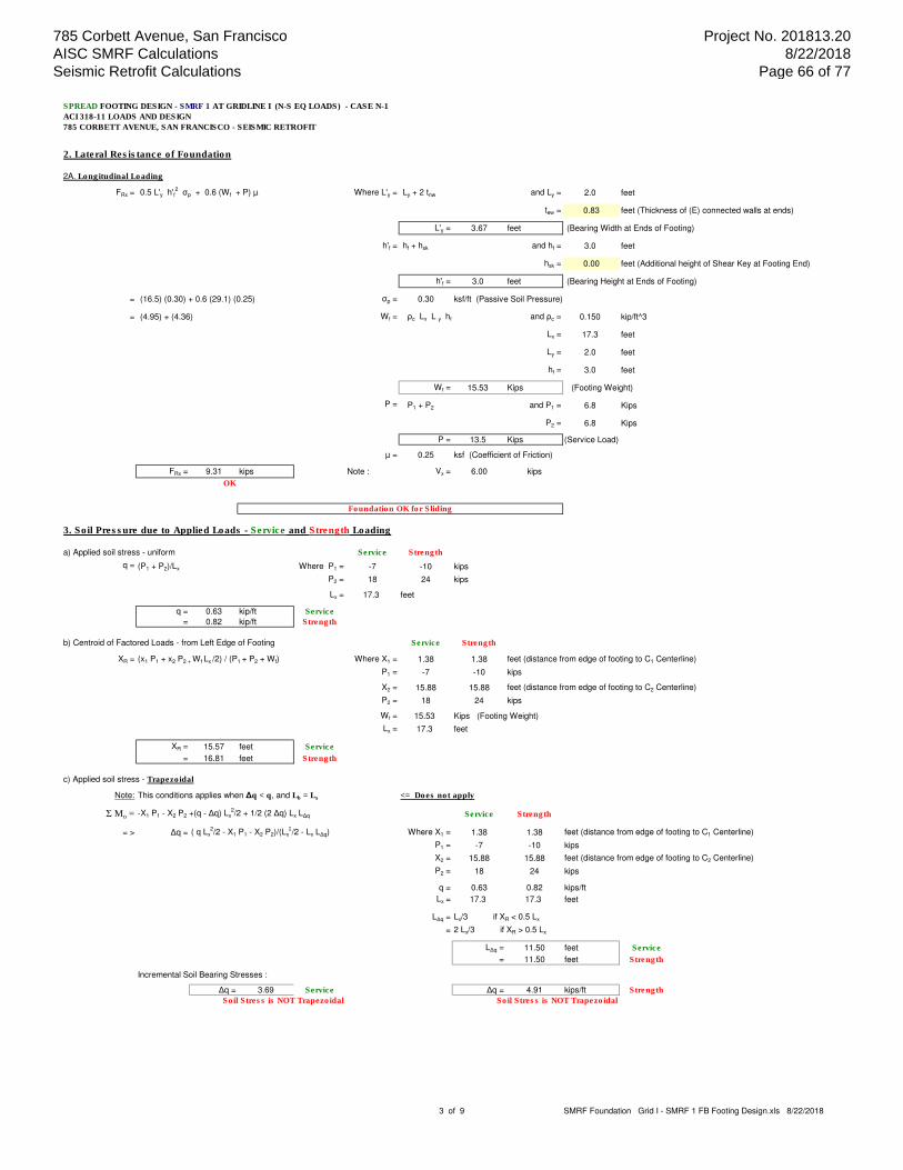
SPREAD FOOTING DESIGN - SMRF 1 AT GRIDLINE I (N-S EQ LOADS) - CASE N-1
ACI 318-11 LOADS AND DESIGN
785 CORBETT AVENUE, SAN FRANCISCO - SEISMIC RETROFIT
2. Lateral Resistance of Foundation
2A. Longitudinal Loading
FRx = 0.5 L'y h'f2 σp + 0.6 (Wf + P) µ Where L'y = Ly + 2 tnw and Ly = 2.0 feet
tew = 0.83 feet (Thickness of (E) connected walls at ends)
L'y = 3.67 feet (Bearing Width at Ends of Footing)
h'f = hf + hsk and hf = 3.0 feet
hsk = 0.00 feet (Additional height of Shear Key at Footing End)
h'f = 3.0 feet (Bearing Height at Ends of Footing)
= (16.5) (0.30) + 0.6 (29.1) (0.25) σp = 0.30 ksf/ft (Passive Soil Pressure)
= (4.95) + (4.36) Wf = ρc Lx L y hf and ρc = 0.150 kip/ft^3
Lx = 17.3 feet
Ly = 2.0 feet
hf = 3.0 feet
Wf = 15.53 Kips (Footing Weight)
P = P1 + P2 and P1 = 6.8 Kips
P2 = 6.8 Kips
P = 13.5 Kips (Service Load)
µ = 0.25 ksf (Coefficient of Friction)
FRx = 9.31 kips Note : Vx = 6.00 kips
OK
3. Soil Pressure due to Applied Loads - Service and Strength Loading
a) Applied soil stress - uniform Service Strength
q = (P1 + P2)/Lx Where P1 = -7 -10 kips
P2 = 18 24 kips
Lx = 17.3 feet
q = 0.63 kip/ft Service
= 0.82 kip/ft Strength
b) Centroid of Factored Loads - from Left Edge of Footing Service Strength
XR = (x1 P1 + x2 P2 + Wf Lx /2) / (P1 + P2 + Wf) Where X1 = 1.38 1.38 feet (distance from edge of footing to C1 Centerline)
P1 = -7 -10 kips
X2 = 15.88 15.88 feet (distance from edge of footing to C2 Centerline)
P2 = 18 24 kips
Wf = 15.53 Kips (Footing Weight)
Lx = 17.3 feet
XR = 15.57 feet Service
= 16.81 feet Strength
c) Applied soil stress - Trapezoidal
Note: This conditions applies when ∆q < q, and Lb = Lx <= Does not apply
Σ Mo = -X1 P1 - X2 P2 +(q - ∆q) Lx2/2 + 1/2 (2 ∆q) Lx L∆q Service Strength
= > ∆q = ( q Lx2/2 - X1 P1 - X2 P2)/(Lx
2/2 - Lx L∆q) Where X1 = 1.38 1.38 feet (distance from edge of footing to C1 Centerline)
P1 = -7 -10 kips
X2 = 15.88 15.88 feet (distance from edge of footing to C2 Centerline)
P2 = 18 24 kips
q = 0.63 0.82 kips/ft
Lx = 17.3 17.3 feet
L∆q = Lx/3 if XR < 0.5 Lx
= 2 Lx/3 if XR > 0.5 Lx
L∆q = 11.50 feet Service
= 11.50 feet Strength
Incremental Soil Bearing Stresses :
∆q = 3.69 Service ∆q = 4.91 kips/ft Strength
Soil Stress is NOT Trapezoidal Soil Stress is NOT Trapezoidal
Foundation OK for Sliding
3 of 9 SMRF Foundation Grid I - SMRF 1 FB Footing Design.xls 8/22/2018
785 Corbett Avenue, San Francisco AISC SMRF Calculations Seismic Retrofit Calculations
Project No. 201813.20 8/22/2018
Page 66 of 77

SPREAD FOOTING DESIGN - SMRF 1 AT GRIDLINE I (N-S EQ LOADS) - CASE N-1
ACI 318-11 LOADS AND DESIGN
785 CORBETT AVENUE, SAN FRANCISCO - SEISMIC RETROFIT
d) Applied soil stress - Triangular <= Governs
Notes: This condition applies when ∆q ≥ q, and Lb ≤ Lx
XR = 15.57 feet = > Large Rotation to Right Service
= 16.81 feet Strength
0.5 Lx = 8.6 feet
i) Rotation to Left - Footing Bearing Length
Lb = 3 ( 0.5 Lx - e) Where 0.5 Lx = 8.6 feet
e = XR - 0.5 Lx and XR = 15.57 feet Service
XR = 16.81 feet Strength
e = 6.94 feet Service
= 8.18 feet Strength
Service Lb = NA feet
Strength = NA feet
ii) Rotation to Right - Footing Bearing Length
Lb = 3 ( 0.5 Lx - e) Where 0.5 Lx = 8.6 feet
e = XR - 0.5 Lx and XR = 15.57 feet Service
XR = 16.81 feet Strength
e = 6.94 feet Service
= 8.18 feet Strength
Lb = 5.05 feet Service
1.33 feet Strength
iii) Resulting Soil Bearing Length and Triangular Pressure
Service Strength
∆q = 2(P1 + P2)/Lb Where P1 = -7 -10 kips
P2 = 18 24 kips
Lb = 5.05 1.33 feet
∆q = 4 kips/ft Service
= 21 kips/ft Strength
e) Applied Soil Stresses - Governing
Service Loads :
Note: Large Rotation to Right
q = 0.00 kips/ft XR = 15.57 feet
∆q = 4.28 kips/ft 0.5 Lx = 8.63 feet
Lb = 5.05 feet
Note: Lo = 12.20 feet (location of soil zero value)
Strength Loads :
Note: Large Rotation to Right
q = 0.00 kips/ft XR = 16.81 feet
∆q = 21.43 kips/ft 0.5 Lx = 8.63 feet
Lb = 1.33 feet
Note: Lo = 15.92 feet (location of soil zero value)
f) Check of Soil Bearing Stress
Service Loads :
σb = qmax / Ly ≤ σb Where qmax = 4.28 kips/ft
Ly = b = 2.00 feet
σb = 2.14 Ksf Service
NG
Strength Loads :
σbu = qu / Ly ≤ σb Where qu = 21.43 kips/ft
Ly = b = 2.00 feet
σb = 10.72 Ksf Strength
Soil Bearing, Shear, and Flexure
Service and Strength Loading
-55
-50
-45
-40
-35
-30
-25
-20
-15
-10
-5
0
5
10
0 5 10 15 20
4 of 9 SMRF Foundation Grid I - SMRF 1 FB Footing Design.xls 8/22/2018
785 Corbett Avenue, San Francisco AISC SMRF Calculations Seismic Retrofit Calculations
Project No. 201813.20 8/22/2018
Page 67 of 77
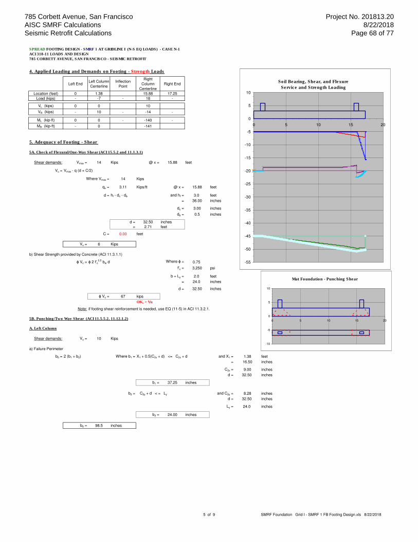
SPREAD FOOTING DESIGN - SMRF 1 AT GRIDLINE I (N-S EQ LOADS) - CASE N-1
ACI 318-11 LOADS AND DESIGN
785 CORBETT AVENUE, SAN FRANCISCO - SEISMIC RETROFIT
4. Applied Loading and Demands on Footing - Strength Loads
Left EndLeft Column
Centerline
Inflection
Point
Right
Column
Centerline
Right End
Location (feet) 0 1.38 15.88 17.25
Load (kips) - -7 - 18 -
VL (kips) 0 0 10
VR (kips) - 10 - -14 -
ML (kip-ft) 0 0 - -140 -
MR (kip-ft) - 0 -141
5. Adequacy of Footing - Shear
5A. Check of Flexural/One-Way Shear (ACI 15.5.2 and 11.1.3.1)
Shear demands: Vmax = 14 Kips @ x = 15.88 feet
Vu = Vmax - q (d + C/2)
Where Vmax = 14 Kips
qu = 3.11 Kips/ft @ x = 15.88 feet
d = hf - dc - db and hf = 3.0 feet
= 36.00 inches
dc = 3.00 inches
db = 0.5 inches
d = 32.50 inches
= 2.71 feet
C = 0.00 feet
Vu = 6 Kips
b) Shear Strength provided by Concrete (ACI 11.3.1.1)
ɸ Vc = ɸ 2 f'c0.5
bw d Where ɸ = 0.75
f'c = 3,250 psi
b = Ly = 2.0 feet
= 24.0 inches
d = 32.50 inches
ɸ Vc = 67 kips
OK, > Vu
Note: if footing shear reinforcement is needed, use EQ (11-5) in ACI 11.3.2.1.
5B. Punching/Two Way Shear (ACI 11.5.5.2, 11.12.1.2)
A. Left Column
Shear demands: Vu = 10 Kips
a) Failure Perimeter
b0 = 2 (b1 + b2) Where b1 = X1 + 0.5(C2x + d) <= C2x + d and X1 = 1.38 feet
= 16.50 inches
C2x = 9.00 inches
d = 32.50 inches
b1 = 37.25 inches
b2 = C2y + d < = Ly and C2y = 8.28 inches
d = 32.50 inches
Ly = 24.0 inches
b2 = 24.00 inches
b0 = 98.5 inches
Mat Foundation - Punching Shear
-10
-5
0
5
10
0 5 10 15 20
Soil Bearing, Shear, and Flexure
Service and Strength Loading
-55
-50
-45
-40
-35
-30
-25
-20
-15
-10
-5
0
5
10
0 5 10 15 20
5 of 9 SMRF Foundation Grid I - SMRF 1 FB Footing Design.xls 8/22/2018
785 Corbett Avenue, San Francisco AISC SMRF Calculations Seismic Retrofit Calculations
Project No. 201813.20 8/22/2018
Page 68 of 77
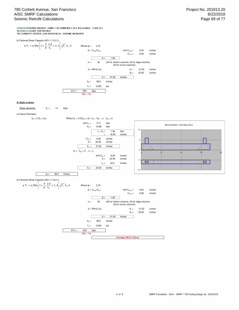
SPREAD FOOTING DESIGN - SMRF 1 AT GRIDLINE I (N-S EQ LOADS) - CASE N-1
ACI 318-11 LOADS AND DESIGN
785 CORBETT AVENUE, SAN FRANCISCO - SEISMIC RETROFIT
b) Factored Shear Capacity (ACI 11.12.2.1)
Where ɸ = 0.75
β = Cmax/Cmin and Cmax = 9.00 inches
Cmin = 8.28 inches
β = 1.09
α = 30 (40 for interior columns, 30 for edge columns,
20 for corner columns)
d = Min(d1,d2) d1 = 31.63 inches
d2 = 33.50 inches
d = 31.63 inches
b0 = 98.5 inches
f'c = 3,250 psi
ɸ Vc = 533 kips
OK, > Vu
B. Right Column
Shear demands: Vu = 14 Kips
a) Failure Perimeter
b0 = 2 (b1 + b2) Where b1 = 0.5(C2x + d) + (Lx - X2) <= C2x + d
and Lx = 17.3 feet
X2 = 15.88 feet
Lx -X2 = 1.38 feet
= 16.50 inches
C2x = 9.00 inches
d = 32.50 inches
b1 = 37.25 inches
b2 = C2y + d <= Ly
and C2y = 8.28 inches
d = 32.50 inches
Ly = 24.0 inches
b2 = 24.00 inches
b0 = 98.5 inches
b) Factored Shear Capacity (ACI 11.12.2.1)
Where ɸ = 0.75
β = Cmax/Cmin and Cmax = 9.00 inches
Cmin = 8.28 inches
β = 1.09
α = 30 (40 for interior columns, 30 for edge columns,
20 for corner columns)
d = Min(d1,d2) d1 = 31.63 inches
d2 = 33.50 inches
d = 31.63 inches
b0 = 98.5 inches
f'c = 3,250 psi
ɸ Vc = 533 kips
OK, > Vu
Footing OK for Shear
d b f' 4 2, b
d α ,
β
4 2Min φ V φ oc
o
c
++=
d b f' 4 2, b
d α ,
β
4 2Min φ V φ oc
o
c
++=
Mat Foundation - Punching Shear
-10
-5
0
5
10
0 5 10 15 20
6 of 9 SMRF Foundation Grid I - SMRF 1 FB Footing Design.xls 8/22/2018
785 Corbett Avenue, San Francisco AISC SMRF Calculations Seismic Retrofit Calculations
Project No. 201813.20 8/22/2018
Page 69 of 77

SPREAD FOOTING DESIGN - SMRF 1 AT GRIDLINE I (N-S EQ LOADS) - CASE N-1
ACI 318-11 LOADS AND DESIGN
785 CORBETT AVENUE, SAN FRANCISCO - SEISMIC RETROFIT
6. Adequacy of Footing - Flexure
6A. Longitudinal Top Reinforcement Check
Flexural demands: Mu = 0 Kip-ft @ x = feet (Inflection Point)
a) Required Reinforcement Ratio (ACI 10.2)
Where f'c = 3.25 Ksi
fy = 60.00 Ksi
Mu = 0
= 0 kip-in
b = Ly = 2.0 feet
= 24 inches
dtop = 33.13 inches
ρr = 0.0000
b) Maximum Reinforcement Ratio (ACI 10.3.4)
Where f'c = 3.25 Ksi
fy = 60.00 Ksi
β1 = 0.85 for f'c ≤ 4.0 Ksi
= 0.85 - 0.05 (f'c - 4.0), ≥ 0.65 for f'c > 4.0 Ksi
β1 = 0.85
εc = 0.003 (ACI Section 10.3.4)
εs = 0.005
ρt = 0.0147
c) Minimum Reinforcement of Flexural Members (ACI 10.5, 7.12.2.1)
ρmin = Max [3 f'c0.5
/fy, 200/fy] ≤ Max [1.33 ρr, 0.0018] Where f'c = 3,250 psi
= Max [0.0029,0.0033] ≤ Max[0.0000,0.0018] fy = 60,000 psi
= Max [0.0033] ≤ Max[0.0018] ρr = 0.0000 (Required Reinforcement Ratio)
ρmin = 0.0018 ≤
d) Required Reinforcement Area
Areq = ρ Ly d2 Where ρ = ρr if ρr ≤ ρmax and ρr ≥ ρmin and ρr = 0.00000
= ρmax if ρr ≥ ρmax ρmax = 0.01468
= ρmin if ρr ≤ ρmin ρmin = 0.00180
Where ρr = 0.0018
Ly = 2.0 feet
= 24.0 inches
dtop = 33.13 inches
Areq = 1.43 in^2 Note: As1 = 2.40 in^2 (reinforcement provided)
OK
6B. Longitudinal Bottom Reinforcement Check
a) Flexural Demands (ACI 15.4.2) Mu
Mu = 0 Kip-ft @ x = 1.38 feet (at face of Left Column)
= -141 Kip-ft @ x = 15.88 feet (at face of Right Column)
Mu = 141 kip-ft
= 1,689 kip-in
qu
b) Required Reinforcement Ratio (ACI 10.2) xf
Where f'c = 3.25 Ksi
fy = 60.00 Ksi
Mu = 1,689 kip-in
b = Ly = 2.0 feet
= 24 inches
dbott = 31.63 inches
ρr = 0.0013
4 - No. 7 Longitudinal Top Bars OK
=
c
2
u
y
c
rf' d b 0.765
M 2-1-1
f
f' 0.85 ρ
+=
sc
c
y
c1t
f
f' 0.85 ρ
εε
εβ
=
c
2
u
y
cr
f' d b 0.765
M 2-1-1
f
f' 0.85 ρ
Soil Bearing, Shear, and Flexure
Service and Strength Loading
-55
-50
-45
-40
-35
-30
-25
-20
-15
-10
-5
0
5
10
0 5 10 15 20
7 of 9 SMRF Foundation Grid I - SMRF 1 FB Footing Design.xls 8/22/2018
785 Corbett Avenue, San Francisco AISC SMRF Calculations Seismic Retrofit Calculations
Project No. 201813.20 8/22/2018
Page 70 of 77

SPREAD FOOTING DESIGN - SMRF 1 AT GRIDLINE I (N-S EQ LOADS) - CASE N-1
ACI 318-11 LOADS AND DESIGN
785 CORBETT AVENUE, SAN FRANCISCO - SEISMIC RETROFIT
c) Required Reinforcement of Flexural Members
Note: Asb = 2.40 in2 (Bottom flexural steel provided)
Areq = ρ b d Where ρ = ρr for ρr ≤ ρt and ρr ≥ ρmin Where ρr = 0.0013
= ρmin for ρr ≤ ρmin* ρt = 0.0147
= 0 Otherwise ρmin = 0.0018
ρ = 0.0018
Note:* for ρr ≤ ρmin condition, check Minimum Reinforcement exception (ACI 10.5.3)
Amin = 1.33 ρr b d Where ρr = 0.0013 (required reinforcement ratio)
b = Ly = 24.0 inches
d = dbott = 31.63 inches
Amin = 1.33 in2
b = Ly = 24.0 inches
d = dbott = 31.63 inches
Areq = in2
6C. Transverse Bottom Reinforcement Check
a) Flexural Demands (ACI 15.4.2) Mu
i) At Left Column
Mu = qu xf2/2 Where qu = 0 Kip/ft @ x = 1.38 feet (at Left Column)
xf = Ly/2 - C1y/2 and Ly = 2.0 feet qu
C1y = 0.7 feet xf
xf = 0.66 feet
Mu = 0 kip-ft
ii) At Right Column
Mu = qu Lx xf2/2 Where qu = 3 Kip/ft @ x = 15.88 feet (at Right Column)
xf = Ly/2 - C2y/2 and Ly = 2.0 feet
C2y = 0.7 feet
xf = 0.66 feet
Mu = 1 kip-ft
iii) Governing Value
Mu = 1 kip-ft
= 8 kip-in
b) Required Reinforcement Ratio (ACI 10.2)
Where f'c = 3.25 Ksi b = Lx = 17.3 feet
fy = 60.00 Ksi = 207 inches
Mu = 8 kip-in dbott = 31.63 inches
ρr = 0.0000
c) Required Reinforcement of Flexural Members
Note: Asb = 13.00 in2 (Bottom flexural steel provided)
Areq = ρ b d Where ρ = ρr for ρr ≤ ρt and ρr ≥ ρmin Where ρr = 0.0000
= ρmin for ρr ≤ ρmin* ρt = 0.0147
= 0 Otherwise ρmin = 0.0018
ρ = 0.0018
Note:* for ρr ≤ ρmin condition, check Minimum Reinforcement exception (ACI 10.5.3) - for Ly > 5.0'
Amin = 1.33 ρr b d Where ρr = 0.0000 (required reinforcement ratio)
b = Lx = 207.0 inches
d = dbott = 33.50 inches
Amin = NA in2
b = Ly = 207.0 inches
d = dbott = 33.50 inches
Areq = 12.48 in2
4 - No. 7 Longitudinal Bottom Bars OK
65 - No. 4 Transverse Bottom Bars OK
=
c
2
u
y
cr
f' d b 0.765
M 2-1-1
f
f' 0.85 ρ
8 of 9 SMRF Foundation Grid I - SMRF 1 FB Footing Design.xls 8/22/2018
785 Corbett Avenue, San Francisco AISC SMRF Calculations Seismic Retrofit Calculations
Project No. 201813.20 8/22/2018
Page 71 of 77
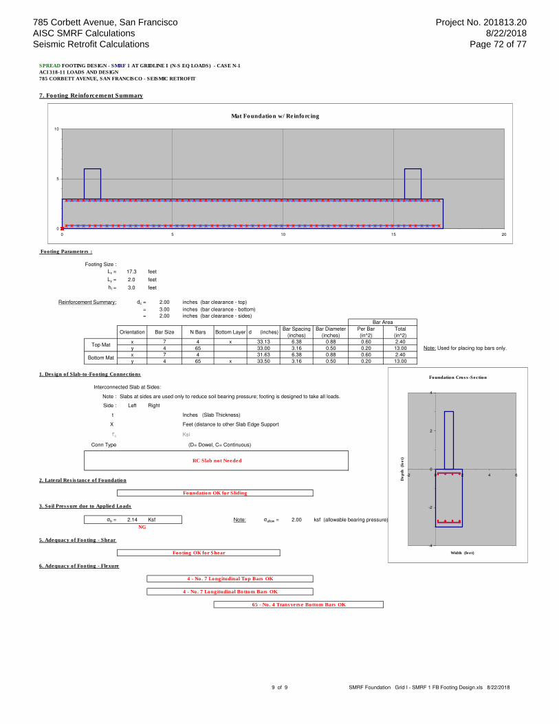
SPREAD FOOTING DESIGN - SMRF 1 AT GRIDLINE I (N-S EQ LOADS) - CASE N-1
ACI 318-11 LOADS AND DESIGN
785 CORBETT AVENUE, SAN FRANCISCO - SEISMIC RETROFIT
7. Footing Reinforcement Summary
Footing Parameters :
Footing Size :
Lx = 17.3 feet
Ly = 2.0 feet
hf = 3.0 feet
Reinforcement Summary: dc = 2.00 inches (bar clearance - top)
= 3.00 inches (bar clearance - bottom)
= 2.00 inches (bar clearance - sides)
Orientation Bar Size N Bars Bottom Layer d (inches)Bar Spacing
(inches)
Bar Diameter
(inches)
Per Bar
(in^2)
Total
(in^2)
x 7 4 x 33.13 6.38 0.88 0.60 2.40
y 4 65 33.00 3.16 0.50 0.20 13.00 Note: Used for placing top bars only.
x 7 4 31.63 6.38 0.88 0.60 2.40
y 4 65 x 33.50 3.16 0.50 0.20 13.00
1. Design of Slab-to-Footing Connections
Interconnected Slab at Sides:
Note : Slabs at sides are used only to reduce soil bearing pressure; footing is designed to take all loads.
Side : Left Right
t Inches (Slab Thickness)
X Feet (distance to other Slab Edge Support
f'c Ksi
Conn Type (D= Dowel, C= Continuous)
2. Lateral Resistance of Foundation
3. Soil Pressure due to Applied Loads
σb = 2.14 Ksf Note: σallow = 2.00 ksf (allowable bearing pressure)
NG
5. Adequacy of Footing - Shear
6. Adequacy of Footing - Flexure
Foundation OK for Sliding
Footing OK for Shear
4 - No. 7 Longitudinal Bottom Bars OK
Top Mat
RC Slab not Needed
4 - No. 7 Longitudinal Top Bars OK
Bottom Mat
65 - No. 4 Transverse Bottom Bars OK
Bar Area
Mat Foundation w/ Reinforcing
0
5
10
0 5 10 15 20
Foundation Cross-Section
-4
-2
0
2
4
-2 0 2 4 6
Width (feet)
De
pth
(f
ee
t)
9 of 9 SMRF Foundation Grid I - SMRF 1 FB Footing Design.xls 8/22/2018
785 Corbett Avenue, San Francisco AISC SMRF Calculations Seismic Retrofit Calculations
Project No. 201813.20 8/22/2018
Page 72 of 77

785 Corbett Avenue, San Francisco AISC SMRF Calculations Seismic Retrofit Calculations
Project No. 201813.20 8/22/2018
Page 73 of 77

SPREAD FOOTING DESIGN - SMRF 1 AT GRIDLINE I (N-S EQ LOADS) - CASE N-1
DETERMINATION OF ADDITIONAL REINFORCEMENT REQUIRED - FIXED BASE COLUMN CONDITION
785 CORBETT AVENUE, SAN FRANCISCO - SEISMIC RETROFIT
1. Parameters
Footing Size :
Lx = 17.25 feet
Ly = 2.00 feet
hf = 3.00 feet
Base Plate Dimensions:
Note: Base Plate design done elsewhere.
N = 16.00 inches (Base Plate - Length)
B = 18.00 inches (Base Plate - Width)
tPL = 1.50 inches (Base Plate - Thickness)
Column: W8x67
d = 9.00 inches (Wide Flange - Depth)
bf = 8.28 inches (Wide Flange - Width)
tf = 0.94 inches (Wide Flange - Thickness)
Zx = 70.1 in3 (Wide Flange - Plastic Section)
A = 19.70 in2 (Wide Flange - Area)
Fy = 50 Ksi
Concrete : f'c = 3.25 Ksi
fy = 60.00 Ksi
ρc = 0.15 kip/ft3
Reinforcement: dc = 2.00 inches (bar clearance - top)
= 3.00 inches (bar clearance - bottom)
= 2.00 inches (bar clearance - sides)
Orientation Bar Size N BarsBottom
Layer
d
(inches)
Bar
Spacing
(inches)
Bar
Diameter
(inches)
Per Bar
(in^2)
Total
(in^2)
Top Mat x 7 4 x 33.13 6.38 0.88 0.60 2.40
Bottom Mat x 7 4 0 31.63 6.38 0.88 0.60 2.40
Soil Parameters : Soil density = 120 pcf
σallow = 2.00 ksf (allowable bearing pressure)
σp = 0.30 ksf/ft (Passive Soil Pressure)
µ = 0.25 ksf (Coefficient of Friction)
Design Parameters : ɸv = 0.75 (Shear; ACI 318-11 9.3.2.3)
Ω = 3.00 (Overstrength Factor - SMRF)
Bar Area
Foundation Cross-Section
-3
-1
1
0 2 4
Width (feet)
De
pth
(f
ee
t)
Mat Foundation - Geometry
-10
-5
0
5
0 5 10 15 20
Page 1 of 4 Fixed Base Condition Grid I - SMRF 1 FB Footing Design.xls 8/22/2018
785 Corbett Avenue, San Francisco AISC SMRF Calculations Seismic Retrofit Calculations
Project No. 201813.20 8/22/2018
Page 74 of 77

SPREAD FOOTING DESIGN - SMRF 1 AT GRIDLINE I (N-S EQ LOADS) - CASE N-1
DETERMINATION OF ADDITIONAL REINFORCEMENT REQUIRED - FIXED BASE COLUMN CONDITION
785 CORBETT AVENUE, SAN FRANCISCO - SEISMIC RETROFIT
2. Additional Required Reinforcement at Columns
a) Column Probable Expected Flexural Capacity
MFB = 100% of Column Flexural Capacity
= 1.0 Zx Fy Where Zx = 70.1 in3 (Wide Flange - Plastic Section)
Fy = 50 Ksi
MFB = 3,505 Kip-in
= 292.1 Kip-ft
b) Required Reinforcement Ratio (ACI 10.2)
Where f'c = 3.25 Ksi
fy = 60.00 Ksi
Mu = MF + MFB for MF = 1,689 kip-in (Footing Flexural Demands)
MFB = 3,505 kip-in (Column Flexural Capacity)
Mu = 5,194 kip-in
b = Ly = 2.0 feet
= 24 inches
dx = 31.63 inches
ρr = 0.00420
c) Reinforcement Ratio Provided
ρw = Asx/(Ly dx) Where Asx = AF + AFB Where AF = 2.40 in2
(Reinforcement Provided - Footing Flexure)
AFB = Reinforcement Required for Resisting Fixed Base Column Flexural Capacity
= (N-1) Ab for N = 4 bars provided
Ab = 0.60 in2
for 7 bars
Note: db = 0.88 in2 (Bar Diameter)
AFB = 1.80 in2
Asx = 4.20 in2
Ly = LB = 2.0 feet
= 24.0 inches
d = 31.63 inches
ρw = 0.00553 (reinforcement ratio provided) Note: D/C Ratio = 0.76 (Demand to Capacity Ratio - Flexure)
OK
Use Additional 3 - # 7 Bars for Column Flexure with DC Ratio = 0.76
=
c
2
u
y
cr
f' d b 0.765
M 2-1-1
f
f' 0.85 ρ
Foundation Cross-Section - Flexural
Reinforcement at Columns
-4
-3
-2
-1
0
1
0 1 2 3
Width (feet)
De
pth
(f
ee
t)
Page 2 of 4 Fixed Base Condition Grid I - SMRF 1 FB Footing Design.xls 8/22/2018
785 Corbett Avenue, San Francisco AISC SMRF Calculations Seismic Retrofit Calculations
Project No. 201813.20 8/22/2018
Page 75 of 77

SPREAD FOOTING DESIGN - SMRF 1 AT GRIDLINE I (N-S EQ LOADS) - CASE N-1
DETERMINATION OF ADDITIONAL REINFORCEMENT REQUIRED - FIXED BASE COLUMN CONDITION
785 CORBETT AVENUE, SAN FRANCISCO - SEISMIC RETROFIT
d) Flexural reinforcement development length (ACI 12.2.2 and 12.2.5)
i) Development Length (ACI 12.2.2 - 12.2.4)
Bar Size = 7
ds = S - db Where S = 3.22 inches (Bar spacing provided)
db = 0.88 inches
ds = 2.34 inches inches (Clear spacing provided)
dc = 2.00 inches (Clear Cover provided)
Provided
(inches)
db = 0.88 inches 2 db = 1.75 inches
OK OK
2 db = 1.75 inches 4 db = 3.50 inches
OK NG
Note: Normal Weight Concrete with uncoated bars is assumed.
Where fy = 60.00 Ksi
Ψs = 1.00 (ACI 12.2.4)
ld = 52.62 db ld = 31.57 db Ψt = Ψe = λ = 1.00
ld = 46.0 inches ld = 27.6 inches f'c = 3.25 Ksi
db = 0.88 inches
ii) Excess Reinforcement (ACI 12.2.5)
l'd = ld ρr/ρw Where ld = 46.0 inches
ρr = 0.0042 (required reinforcement ratio)
ρw = 0.0055 (reinforcement ratio provided)
l'd = 34.9 inches (Required development length)
iii) Available Anchorage length
Lda = xf - dcs > l'd Where xf = 1.38 feet (Cantilever Length at Column Centerline)
= 16.50 inches
dcs = 2.00 inches (bar clearance - sides)
Lda = 14.50 inches
NG
Clear Cover 2.00
Use Additional 3 - # 7 Bars for Column Flexure; Use 0 in Development Length beyond Ends of Base
Plates - Bend Bars at Footing Ends and connect T and B bars together to form Cage.
Clear Spacing 2.34
Equations
Values
Lower Limit Upper Limit
b
c
etsyd
f' 25
f
ΨΨΨ=
λd
l b
c
etsyd
f' 2.5
f
40
3
ΨΨΨ=
λd
l
Foundation Cross-Section - Flexural
Reinforcement at Columns
-4
-3
-2
-1
0
1
0 1 2 3
Width (feet)
De
pth
(f
ee
t)
Page 3 of 4 Fixed Base Condition Grid I - SMRF 1 FB Footing Design.xls 8/22/2018
785 Corbett Avenue, San Francisco AISC SMRF Calculations Seismic Retrofit Calculations
Project No. 201813.20 8/22/2018
Page 76 of 77

SPREAD FOOTING DESIGN - SMRF 1 AT GRIDLINE I (N-S EQ LOADS) - CASE N-1
DETERMINATION OF ADDITIONAL REINFORCEMENT REQUIRED - FIXED BASE COLUMN CONDITION
785 CORBETT AVENUE, SAN FRANCISCO - SEISMIC RETROFIT
3. Foundation Demands at Fixed Base Columns
a) Column Fixed Base Plastic Shear Demands
VP = MP / d Where MP = Fy Zx for Fy = 50 Ksi
Zx = 70.1 in3 (Wide Flange - Plastic Section)
MP = 3,505 Kip-in
d = 31.63 inches (Efffective depth of footing)
VP = 110.8 Kips
b) Amplified Column Axial Demands - Overstrength Shear Demands on Foundation
PU = Max ( Abs (P1), Abs (P2) ) Where P1 = -10 Kips
P2 = 24 Kips
PU = 23.9 Kips
VO = Ω PU Where Ω = 3.00 (Overstrength Factor - SMRF)
PU = 23.9 Kips
VO = 71.6 Kips
c) Controlling Shear Demands on Foundation
VU = Max ( VP, VO ) Where VP = 110.8 Kips (Column Plastic Shear)
VO = 71.6 Kips (Column Overstrength Demands)
VU = 110.8 Kips
4. Foundation Capacity at Fixed Base Columns
a) Shear Strength provided by Concrete (ACI 11.3.1.1)
VC = 2 f'c0.5
bw d Where f'c = 3.25 Ksi
= 3,250 psi
b = Ly = 2.0 feet
= 24.0 inches
d = 31.63 inches (Efffective depth of footing)
VC = 65 kips
b) Shear Strength provided by Shear Reinforcement (ACI 11.3.1.1)
Note: Assume transverse flexural reinforcement provided for footing is part of a reinrforcement cage.
VS = AS Fy d / S (11-15) AS = 0.40 for No. 4 bars => hoops (from Footing Design)
≤ 4 VC Fy = 50 Ksi
d = 31.63 inches (Efffective depth of footing)
S = 3.16 inches (bar spacing - from Footing Design)
VS = 199.9 kips
b) Factored Shear Capacity of Footing (ACI 11.1)
ɸ Vn = ɸ ( VC + VS) Where ɸ = 0.75 (Shear; ACI 318-11 9.3.2.3)
VC = 65 kips
VS = 199.9 kips
ɸ Vn = 198.6 Kips Note: VU = 110.8 Kips
OK
Footing OK for Shear ; Use # 4 hoops @ 3.0" to reinforce Footings at Column locations.
Page 4 of 4 Fixed Base Condition Grid I - SMRF 1 FB Footing Design.xls 8/22/2018
785 Corbett Avenue, San Francisco AISC SMRF Calculations Seismic Retrofit Calculations
Project No. 201813.20 8/22/2018
Page 77 of 77