Embed Size (px)
Citation preview

IISEE Lecture Note 2017
RC Structures (1)
DESIGN FOR FLEXURE, SHEAR AND BOND
By
Dr. Susumu Kono Institute of Innovative Research Tokyo Institute of Technology
International Institute of Seismology and Earthquake Engineering,
Building Research Institute

Advanced RC Structures (2017) S. Kono
2017
Lecture Note on
The Performance Based Design of Reinforced Concrete Structures
DESIGN FOR FLEXURE, SHEAR AND BOND
By
Dr. Susumu Kono Institute of Innovative Research Tokyo Institute of Technology
Advanced RC Structures (2017) S. Kono
i
Table of Contents
1 LOAD-DEFLECTION RELATION OF RC MEMBERS 1
2 DESIGN FOR FLEXURAL CRACKING 2
2.1 Introduction 2
2.2 Basic assumptions 2
2.3 Cracking moment 2 2.3.1 Equivalent moment of inertia 2 2.3.2 Cracking moment 3 2.3.3 Example:Equivalent moment of inertial and the cracking moment 3
2.4 Axial force at cracking 5 2.4.1 Compressive cracking force 5 2.4.2 Tensile cracking force 5
3 DESIGN FOR ULTIMATE FLEXURE 7
3.1 Introduction 7
3.2 Assumptions 7
3.3 Ultimate flexural moment 7 3.3.1 Stress-strain relations of concrete and equivalent stress block 7 3.3.2 Ultimate flexure moment of doubly reinforced concrete beams 9
4 DESIGN FOR SHEAR 13
4.1 Introduction 13
4.2 The Concept of Shear Stresses 14 4.2.1 Shear stress for an elastic and homogeneous member 14 4.2.2 Shear stress for a reinforced concrete member before cracking 15 4.2.3 Shear stress for a reinforced concrete member after cracking 16
4.3 The Mechanism of Shear Resistance in Reinforced Concrete Beams without Web Reinforcement 18
4.3.1 The Formation of Diagonal Cracks 18 4.3.2 Equilibrium in the Shear Span of a Beam 19 4.3.3 The Principal Mechanisms of Shear Resistance 21 4.3.4 Size Effects 28 4.3.5 Shear Failure Mechanisms 29
4.4 The Mechanism of Shear Resistance in Reinforced Concrete Beams with Web Reinforcement 31

Advanced RC Structures (2017) S. Kono
ii
4.4.1 The Role of Web Reinforcement 31 4.4.2 The Truss Mechanism 32
5 DESIGN FOR BOND 36
5.1 Introduction 36
5.2 Basic Theory for Bond 36
6 SHEAR DESIGN OF RC MEMBERS BASED ON ‘DESIGN GUIDELINES FOR EARTHQUAKE RESISTANT REINFORCED CONCRETE BUILDINGS BASED ON INELASTIC DISPLACEMENT CONCEPT’ (1997) 39
6.1 Fundamental concept 39 6.1.1 Plastic theory 39
6.2 Design for shear of beams and columns 40 6.2.1 Code equations for shear strength of beams and columns 40 6.2.2 Explanations on shear strength without plastic hinge rotation 42 6.2.3 Truss mechanism at a transition region 49 6.2.4 Reduction of shear capacity due to plastic hinge rotation 50 6.2.5 Validation of the equations 51 6.2.6 Design examples 53
6.3 Design for bond 57 6.3.1 Code equations 57 6.3.2 Effect of bond strength on Shear strength 59 6.3.3 Design examples 59
6.4 Design for shear of shearwalls 63 6.4.1 Shear cracking strength 63 6.4.2 Shear strength and for a hinge region 63 6.4.3 Design examples 66
7 AIJ STANDARD FOR STRUCTURAL CALCULATION OF REINFORCED CONCRETE STRUCTURES, REVISED IN 1991 68
7.1 Introduction 68
7.2 Design for Shear 68 7.2.1 Art. 16 Shear Reinforcement in Beams and Columns 68
7.3 Design for Development, Anchorage and Lap Splices 75
8 SHEAR DESIGN OF RC MEMBERS BASED ON ‘DESIGN GUIDELINES FOR EARTHQUAKE RESISTANT REINFORCED CONCRETE BUILDINGS BASED ON ULTIMATE STRENGTH CONCEPT’ (1991) 78
8.1 Plastic theory 78

Advanced RC Structures (2017) S. Kono
iii
8.1.1 The lower bound theorem 78 8.1.2 The upper bound theorem 78
8.2 Scope 78
8.3 Shear strength of beams and columns 78 8.3.1 The first term (contribution from the truss action) 79 8.3.2 The second term (contribution from the arch action) 80 8.3.3 Integration of the truss and arch actions 80 8.3.4 Coefficients for members without plastic hinges 81 8.3.5 Coefficients for members with plastic hinges 82 8.3.6 Minimum reinforcement 83
8.4 Shear strength of walls 83 8.4.1 Shear strength 83 8.4.2 Equivalent wall widths 83 8.4.3 Effective factor of concrete for a non-hinge region 83 8.4.4 Effective factor of concrete for a hinge region 83 8.4.5 Beam between stories 84 8.4.6 Minimum reinforcement 84
8.5 Bond 84 8.5.1 Design bond stress 84 8.5.2 Bond strength 84
REFERENCES 85
HOW TO REACH US 85

Advanced RC Structures (2017) S. Kono
1
1 LOAD-DEFLECTION RELATION OF RC MEMBERS
Concrete is a quasi-brittle material and its deformation capability is limited. However, it is possible to make concrete members ductile as shown in Figure 1.1 by combining brittle concrete with ductile reinforcing steel bars.
Figure 1.1 Moment – curvature relation of a RC beam(6)
Ultimate state (Compression failure of concrete at the compression fiber)
Tensile yielding of reinforcement
Cracking
Curvature
Moment

Advanced RC Structures (2017) S. Kono
2
2 DESIGN FOR FLEXURAL CRACKING 2.1 Introduction Concrete carries tensile force before cracking. The stiffness of members before
cracking is higher than that after cracking. This chapters demonstrates how to obtain the cracking moment, cM .
2.2 Basic assumptions The following basic assumptions are made to compute the cracking moment, cM .
Bernoulli’s theorem is satisfied (plane-sections-remain-plane assumption). Stress-strain relation of concrete is elastic. Stress-strain relation of reinforcing bars is elastic. Concrete carries tensile force.
2.3 Cracking moment 2.3.1 Equivalent moment of inertia Consider the section which has the center of the gravity of the section is located below the half depth by “e” as shown in Figure 2.1(a). Strictly speaking, the moment of inertia of this reinforced concrete section is expressed as:
2 21 3 ( 1) ( 1)e e t t c cI I n a y n a y (2.1)
where Ie3 is expressed in Eq. (2.3). If the overlapping of concrete and reinforcement is allowed, the equation can be simplified as:
2 22 3e e t t c cI I na y na y (2.2)
Neglect the reinforcement and assume that the whole section is filled with concrete. The moment of inertia about the C.G. is expressed as:
3
23 12e
bDI bDe (2.3)
(a) Section (b) Elevation
Figure 2.1 A reinforced concrete beam
D e × C.G
b
ac yc
yt at
× Half depth point

Advanced RC Structures (2017) S. Kono
3
2.3.2 Cracking moment Stress at the tensile fiber can be expressed as:
2
c ct
e e
M MDf
I Z (2.4)
where Ie is either of Ie1, Ie2 and Ie3. When the tensile stress reaches the modulus of rupture, rf , expressed as follows, the section cracks.
20.56 ' ( / )r cf f N mm (2.5)
Hence, the cracking moment can be expressed as: c r eM f Z (2.6)
2.3.3 Example:Equivalent moment of inertial and the cracking moment Let us compute the cracking moment of the doubly reinforced concrete beam in Figure 2.2. 400b mm
60c td d mm
640d mm 700D mm
Concrete Compressive strength ' 24cf MPa
Unit weight 324kN m
Figure 2.2 Section of a reinforced concrete beam
Reinforcement Tensile reinforcement SD345 3-D22 2387 3 1161ta mm
Compressive reinforcement SD345 3-D22 2387 3 1161ca mm
Young’s modulus of concrete and reinforcing bars are;
12
3
12
3
2
'33500
24 60
24 2433500
24 60
24700 / 24.7
cc
fE
N mm GPa
(2.7)
2205000 / 205sE N mm GPa (2.8)
b
D
dc
d=D-dt
dt

Advanced RC Structures (2017) S. Kono
4
Then the modular ratio, n, is
205
8.3024.7
s
c
E GPan
E GPa
(2.9) The modulus of rupture is:
20.56 ' 0.56 24 2.74 /r cf f N mm (2.10)
Strictly, the moment capacity is:
32 2
1
322
10 4
( 1) ( 1)12
400 700(8.3 1) 1161 (350 60) (8.3 1) 1161 350 60
12
1.29 10
e t t c c
bDI n a y n a y
mm
(2.11)
10 42
1
7 3
1.29 10
350
3.69 10
ee
t
I mmZ
H mm
mm
(2.12)
2 7 3
1 1 2.74 / 3.69 10
101.2c r eM f Z N mm mm
kN m
(2.13)
If the overlapping of concrete and reinforcement is allowed, the moment capacity is:
32 2
2
322
10 4
12
400 7008.3 1161 (350 60) 8.3 1161 350 60
12
1.31 10
e t t c c
bDI na y na y
mm
(2.14)
10 4
7 322
1.31 103.74 10
350e
et
I mmZ mm
H mm
(2.15)
2 7 3
2 2 2.74 / 3.74 10 102.6c r eM f Z N mm mm kN m (2.16)
If reinforcement is neglected, the moment capacity is:
3 3
10 43
400 7001.14 10
12 12e
bDI mm
(2.17)
10 4
7 333
1.14 103.27 10
350e
et
I mmZ mm
H mm
(2.18)

Advanced RC Structures (2017) S. Kono
5
2 7 33 3 2.74 / 3.27 10 89.6c r eM f Z N mm mm kN m (2.19)
It is seen that Mc1 and Mc2 are nearly same but Mc3 is 11.5% less than Mc1. 2.4 Axial force at cracking 2.4.1 Compressive cracking force Under concentric compression, cracks do not form.
2.4.2 Tensile cracking force When the stress reaches the tensile strength, 'tf , the tensile force can be obtained as
follows assuming that concrete and reinforcement are elastic. (a) Equilibrium External and internal forces are equilibrated in axial direction. c sN T T
(2.20) cT :Tensile resultant force of concrete
sT :Tensile resultant force of reinforcement
(b) Strain compatibility Strain at the section is uniform and expressed as: st c (2.21)
(c) Stress-strain relation Since concrete and reinforcement are assumed elastic, stress and strain relations are expressed as: c c cE (concrete)
(2.22) st s stE (reinforcement)
(2.23) Combining Eqs. (2.20) through (2.23) for a column section in ,
1
1
c c c c st s st
c c c st c c
c c st c c
st c c
N A E a E
A E a nE
bhE a n E
bh a n E
(2.24)
where n is the section modulus in Eq. (2.9)

Advanced RC Structures (2017) S. Kono
6
When the concrete stress, c c cE , reaches the cracking strength, 'tf , a crack forms
and the tensile force can be expressed as: 1 'c st tN bh a n f (2.25)
Figure 2.3 Section of a reinforced concrete beam
b
ast: Total area of longitudinal reinforcement
h

Advanced RC Structures (2017) S. Kono
7
3 DESIGN FOR ULTIMATE FLEXURE 3.1 Introduction It is important to know the ultimate flexural moment capacity at failure and the failure
mode when the member is subjected to unexpectedly large load. It should be noted that concrete and reinforcement are not elastic anymore at this stage. 3.2 Assumptions The following assumptions are made to compute the ultimate flexural strength, nM .
Bernoulli’s theorem is satisfied (plane-sections-remain-plane assumption). Plastic condition of stress-strain relation of concrete is considered. Concrete stress
block indices 1k , 2k , 3k , and the ultimate compressive strain, cu , are assumed
to be known. Elastic-plastic condition of stress-strain relation of reinforcing bars is considered. Concrete DOES NOT carry tensile force.
3.3 Ultimate flexural moment 3.3.1 Stress-strain relations of concrete and equivalent stress block Assuming that the stress-strain relation of concrete is expressed in Figure 3.1, stress
block coefficients represent the area under the curve and the location of the centroid. 1 3 'c cuk k f =equivalent area under the curve
2 cuk =the location of the centroid of the area under the curve in terms of cu
1k :coefficient to represent the average stress when the compressive fiber reaches
the ultimate compressive strain, cu .
2k :coefficient to represent the location of centroid of the area under the curve in
terms of cu .
3k :coefficient to represent the difference in compressive strengths of test
cylinders and members
Table 3.1 Concrete stress block coefficients
f’c≦27.4 N/mm2 f’c>27.4 N/mm2 εcu 0.003 k1 0.85 0.85-0.05(f’c – 27.4) / 6.84 k2 0.85 k3 0.5 k1

Advanced RC Structures (2017) S. Kono
8
Figure 3.1 Stress – strain relation of concrete in structural members and the meaning of stress
block(6)
Figure 3.2 Stress – strain relation of reinforcing bars(6)
Strain, εc
Average stress
Strain Strain
Yield plateau
Strain hardening
Elasto-plastic assumption
Elasto-plastic assumption
Ordinary reinforcing bars with yield plateau
Reinforcing bars without yield plateau
Centroid
Stress
Stress
Stress, σc
σ-ε relation of standard cylinder
εcu 0
σc = g(εc)
σ-ε relation of concrete in members
f’c
k3f’c
k1k3f’c
(1-k2)εcu
k2εcu

Advanced RC Structures (2017) S. Kono
9
3.3.2 Ultimate flexure moment of doubly reinforced concrete beams 3.3.2.1 Basic equations (a) Equilibrium External and internal forces should be equal in terms of axial force and moment. Equilibrium for axial force c s sN C C T (3.1)
Equilibrium for moment 2c n n s n c s nM C x k x C x d T d x (3.2)
(b) Strain compatibility Based on the Bernoulli’s theorem, the strain at arbitrary height of the section can be expressed with the ultimate strain of compressive fiber, cu .
st sc cu
n n c nd x x d x
(3.3)
(c) Stress-strain relation It is defined that the ultimate flexural moment is reached when the strain at the compressive fiber reaches the ultimate strain( 0.003c cu ). At this stage, concrete
does not follow the elastic relation, c c cE , anymore. Reinforcement is either
elastic ( st s stE ) or plastic ( st yf ).
(a) Section (b) Strain (c) Stress (d)Equivalent (e) External
distribution distribution stress force
Figure 3.3 Ultimate condition of a rectangular reinforced concrete beam
b
Cc
εcu
xn
dt
d
dc
εst
N
Mn
T= astσst
k2xn
σst
asc
ast
εsc σsc Cs = ascσsc

Advanced RC Structures (2017) S. Kono
10
3.3.2.2 Depth of the neutral axis, nx
Flexural failure can be categorized into three failure modes; flexural tensile failure, flexural compression failure, and balanced failure. No matter which of three failure modes is taken, the strain at the compressive fiber always reaches the ultimate limit strain, cu , that is, 0.003c cu . Hence, cC , sC , sT can be computed based on
the ultimate strain and the neutral axis depth, nx .
Equivalent stress block is used to represent the compressive resultant force of concrete,
cC .
1 3 'c c nC k k f x b (3.4)
The compressive resultant force of steel, sC , can be computed based on its strain,
n csc cu
n
x d
x
.
s y cC f a (yielded)or s s sc cC E a (elastic) (3.5)
The tensile resultant force of steel, sT , can be computed based on its strain,
nst cu
n
d x
x
, like sC .
s y tT f a (yielded)or s s st tT E a (elastic) (3.6)
Substitute into the axial force equilibrium, c s sN C C T to obtain nx .
Case 1. When both compressive reinforce and tensile reinforcement have yielded, the equilibrium is: 1 30 'c n y c y tk k f x b f a f a (3.7)
Case 2. When compressive reinforcement is elastic and tensile reinforcement has yielded, the equilibrium is:
1 3
1 3
0 '
0 '
c n s sc c y t
n cc n s cu c y t
n
k k f x b E a f a
x dk k f x b E a f a
x
(3.8)
Case 3. When compressive reinforcement has yielded and tensile reinforcement is elastic, the equilibrium is:
1 3
1 3
0 '
0 '
c n y c s st t
nc n y c s cu t
n
k k f x b f a E a
d xk k f x b f a E a
x
(3.9)
Case 4. When both compressive reinforce and tensile reinforcement are elastic, the equilibrium is:
1 3
1 3
0 '
0 '
c n s sc c s st t
n c nc n s cu c s cu t
n n
k k f x b E a E a
x d d xk k f x b E a E a
x x
(3.10)

Advanced RC Structures (2017) S. Kono
11
Obtain nx for four cases. Recompute the strains of compressive and tensile
reinforcements, n csc cu
n
x d
x
and nst cu
n
d x
x
and compare the results with the
assumptions. There should be only one case in which the assumption and the result are consistent and this case turns out to be the correct answer. The assumption and the result in other cases are inconsistent and is judged as wrong. 3.3.2.3 Ultimate flexural moment capacity, nM
The ultimate flexural moment, nM , can be computed using the correct nx . When no
axial force acts, the moment can be computed about any height of the section. In the computation, the coefficient 2k is used. 2n c n n s n c s nM C x k x C x d T d x (3.11)
3.3.2.4 Amount of reinforcement for balanced failure There is a case that the tensile reinforcement yields exactly when strain of concrete at
the compression fiber reaches the ultimate strain. This failure is called balanced failure. 3.3.2.5 Example of computing the ultimate flexural moment capacity The ultimate flexural moment for a RC beam in Section 2.3.3 is computed in this
section. Case 2 (compressive reinforcement is elastic and tensile reinforcement has yielded is assumed. 1 3 ' 0.85 0.85 24 400c c n nC k k f x b MPa x mm
260205 0.003 1161n c n
s s cu cn n
x d x mmC E a GPa mm
x x
(3.12)
2345 1161s y tT f a MPa mm
Substitute the above three terms into the equilibrium, c s sN C C T and solve for
nx . It is noted that 0N since the beam has no axial force.
59.1nx mm
Strain of the compressive reinforcement is:
59.1 600.003 0.000042 0.00168
59.1n c
sc cu yn
x d mm mm
x mm
as assumed.
Strain of the tensile reinforcement is:

Advanced RC Structures (2017) S. Kono
12
640 59.10.003 0.0294 0.00168
59.1n
st cu yn
d x mm mm
x mm
as assumed.
Since the assumptions on the reinforcement strain is satisfied, this case turns out to be right. The force resultants are: 1 3 ' 0.85 0.85 24 59.1 400 410c c nC k k f x b MPa mm mm kN
2205 ( 0.000042) 1161 9.915s s sc cC E a MPa mm kN
(3.13) 2345 1161 401s y tT f a MPa mm kN
These terms satisfies the equilibrium, 0 c s sN C C T . The ultimate flexural
moment can be computed about any height of the section. It is computed about the neutral axis here.
2
410 (59.1 0.425 59.1 )
9.92 59.1 60
401 640 59.1
247
n c n n s n c s nM C x k x C x d T d x
kN mm mm
kN mm mm
kN mm mm
kNm
(3.14)

Advanced RC Structures (2017) S. Kono
13
4 DESIGN FOR SHEAR 4.1 Introduction It may be said that the behavior and failure mechanisms of reinforced concrete members subjected to pure bending has already been studied sufficiently and understood very well. Also, the behavior of a reinforced concrete member under pure bending can be rationally predicted based on the Bernoulli’s theory which uses a simple assumption that plane sections before bending remain plane after bending. Therefore, with respect to flexural design concept and methods, there is little disagreement between the design codes of various countries. On the other hand, progress in the understanding of the behavior and failure mechanisms of members subjected to shear with flexure and/or axial load has been somewhat slow and hundreds of publications speak for the complexity of the problem. Nonetheless, all aspects of shear behavior have not been taken into account in any shear design methods currently used. Since the data obtained from shear tests scatter more widely than those obtained from flexural tests, in general, the shear strength of a member is estimated more conservatively than the flexural strength in the current design codes. This can be seen from the fact that, in the ACI code as well as others, the semi-empirical equations to calculate the nominal shear strength of a member have been derived as to give a line close to the lower bound of the background test data. Also a higher safety factor is used in the design for shear than for flexure. For example, in the ACI code, the strength reduction factor φof 0.85 is adopted in the design for shear while φof 0.90 is used for the flexure. A shear failure of a reinforced concrete member can occur in a brittle manner if the reinforcing details are inadequate. Consequently an attempt must be made to suppress such a failure. In earthquake-resistant structures in particular, heavy emphasis is placed on ductility, and for this reason the designer must ensure that a shear failure can never occur. This implies that when ductility is essential, the shear strength of the member must be higher than flexural strength which could possibly develop at an ultimate state, even if a frame analysis indicates that the maximum moment induced in the member under design loads does not reach to the flexural strength of the member. This design concept has been typically introduced in the Capacity Design of the New Zealand Code (NZS3101:1995). It is still expedient to use the classical concepts of shear stresses in homogeneous, isotropic, elastic bodies when predicting initial crack formation. However, with the development of cracks an extremely complex pattern of stresses ensues, and it becomes difficult to predict precisely the actual behavior of the member. To solve this problem, extensive experimental and theoretical work, particularly in recent years, has greatly extended the identification of various shear resisting mechanisms. Thus the approach to the design for shear in reinforced concrete has been significantly improved in the design codes of various countries. In this class note, basic theories for shear and bond are briefly reviewed and then shear design methods adopted in the ACI 318-08 code, the AIJ Standard based on allowable stress design (1999) and the AIJ Design Guidelines based on inelastic displacement concept (1997) are to be introduced.

Advanced RC Structures (2017) S. Kono
14
4.2 The Concept of Shear Stresses The following text was composed by extracting passages from the book entitled “Reinforced Concrete Structures” by R. Park and T. Paulay published by John Wiley & Sons, Inc. in 1975, with modifications. It is old from the viewpoint of the published year but still the best book to understand the background of the shear design concepts and the methods adopted in the current design codes of various countries. 4.2.1 Shear stress for an elastic and homogeneous member Consider a simply supported beam under loading as shown in Figure 4.1(a).
Equilibrium condition in horizontal direction for the free body in Figure 4.1(f) is ydTdxybyv
(4.1)
(a) A simply supported beam under vertical load
(b) Free body (c) Normal Strain (d) Normal stress (e) Shear stress
(f) Stresses acting on the shaded free body
Figure 4.1 Shear stress for elastic and homogeneous member
M
dx
x
y h
V+dV
V
M+dM
T+dT
compression
v y
T
y y
v y
y y d y
tension
compression
tension
x
y
dx

Advanced RC Structures (2017) S. Kono
15
where yv is the shear stress, yb is the section width, and yT is the tension
resultant action on the shaded free body. The increment in yT at distance dx is
ydT and it can be expressed as:
ySxI
xdMdyyby
xI
xdM
dyybyxI
xdMdyybydydT
y
h
y
h
y
h
2/
2/2/
(4.2)
where xI is the second moment of inertia and yS is the first moment of inertia about y=0 where the center of gravity locates. From Eqs. (4.1) and (4.2)),
xIyb
ySxV
xIdxyb
ySxdM
dxyb
ydTyv
(4.3)
For a prismatic beam with a rectangular section, 30
2
V xv y
bh can be obtained
from 2
02 4 8
bh h bhS y and
3
( )12
bhI x
4.2.2 Shear stress for a reinforced concrete member before cracking Using the notation in Figure 4.2, the equilibrium of the shaded part of the beam element will be satisfied when the horizontal shear stress is
xIyb
ySxVyv
(4.4) Since the distance between the compression and tension resultants, z, is expressed as
,I x
z x yS y
.
(4.5) Hence,
,
V xv y
b y z x y
(4.6) It is seen that the stress state before cracking is identical to the state in Section 4.2.1.

Advanced RC Structures (2017) S. Kono
16
4.2.3 Shear stress for a reinforced concrete member after cracking Consider a reinforced concrete beam with cracking as shown in Figure 4.3. The equilibrium of an arbtrary free body located below the neutral axis is written as:
jdyb
V
dx
Md
jdyb
dx
jdMd
yb
dx
xTd
ybyv
xTdyvdxyb
w
w
w
w
w
1
)/(1
1
(4.7) or
jd
V
dx
xdTybyvq w
(4.7)’ where q is the bond force per unit length of the member and termed shear flow. As Figure 4.3 shows, the horizontal force transferred across the cracked zone of the section remains constant; hence the shear flow in the tension zone is constant. It is evident that shear stress depends on the width of the web, illustrated for a particular example in Figure 4.3. Since the concrete below the neutral axis (NA) is assumed to be in a state of pure shear, this equation has been used as the measure of diagonal tension in the cracked tension zone of a reinforced concrete beam. This also implies that vertical shear stresses are transmitted in this fashion across sections, irrespective of the presence of flexural cracks. In many design codes including the AIJ Standard, this traditional shear stress equation is still used. It is a convenient " index " to measure shear intensity, but it cannot be considered as a shear stress at any particular locality in a cracked reinforced concrete beam. For convenience the ACI adopted, as an index of shear intensity, the simple equation
db
Vv
w
(4.8) In certain cases, the maximum shear stress could occur at a fiber other than at the web of the section. When the flange of a T section carries a large compression force, as over the shaded area to the right of section 1 in Figure 4.3, the shear at the flange-web junction may become critical, and horizontal reinforcement in the flange may be
Assume that jd=constant

Advanced RC Structures (2017) S. Kono
17
needed. In beams supporting floors of buildings, the flexural reinforcement in the slab is usually adequate for this purpose.
Figure 4.2 Shear force, shear flow, and shear stresses in a homogeneous isotropic elastic beam
Figure 4.3 Shear stress across an idealized cracked reinforced concrete section
Shear flow varies across the section.
Shear flow is constant below the neutral axis.
(a)
(b)
(c) (d) (e) (f) (g)
(a) (b) (c) (d)
Section 1-1 may be critical in shear.

Advanced RC Structures (2017) S. Kono
18
4.3 The Mechanism of Shear Resistance in Reinforced Concrete Beams without Web Reinforcement
---------------------------------------------------------------------------------------------------------- In practical design, web reinforcement is normally required to be provided for beams in the form of stirrups. Hence, you may wonder why the mechanism of shear resistance in beams without web reinforcement is discussed in the following sections. The reason may be explained as follows. The shear strength of beams provided by so-called beam action and arch action could be identified through the study for the case of beams without web reinforcement. Also, based on such studies, the most of the current design codes assess the contribution of concrete to the shear resistant capacity of reinforced concrete members. For example, in the ACI code, the nominal shear strength of beams, Vn, is calculated as the sum of the strength provided by concrete, Vc, and that by shear reinforcement Vs, that is, Vn = Vc + Vs. In this equation, Vc is calculated using the empirical equations obtained from the shear tests on beams without shear reinforcement. ---------------------------------------------------------------------------------------------------------- 4.3.1 The Formation of Diagonal Cracks In a reinforced concrete member, flexure and shear combine to create a biaxial state of stress. Cracks form when the principal tensile stresses reach the tensile strength of the concrete. In a region of large bending moments, these stresses are greatest at the extreme tensile fiber of the member and are responsible for the initiation of flexural cracks perpendicular to the axis of the member. In the region of high shear force, significant principal tensile stresses, also referred to as diagonal tension, may be generated at approximately 45 degree to the axis of the member as can be seen in Figure 4.4. These may result in inclined (diagonal tension) cracks. With few exceptions these inclined cracks are extensions of flexural cracks. Only in rather special cases, as in webs of flanged beams, are diagonal tension cracks initiated in the vicinity of the neutral axis. The principal stress concept is of little value in the assessment of subsequent behavior unless the complex distribution of stresses in the concrete after cracking is considered. Either a reinforced concrete flexural member collapses immediately after the formation of diagonal cracks, or an entirely new shear carrying mechanism develops which is capable of sustaining further load in a cracked beam. The diagonal cracking load originating from flexure and shear is usually much smaller than would be expected from principal stress analysis and the tensile strength of concrete. This condition is largely due to
1. the presence of shrinkage stresses, 2. the redistribution of shear stresses between flexural cracks, and 3. the local weakening of a cross section by transverse reinforcement, which
causes a regular pattern of discontinuities along a beam. In the early stages of reinforced concrete design, diagonal cracking was considered to be undesirable. However, it is now recognized that diagonal cracking under service load conditions is acceptable, provided that crack widths remain within the same limits accepted for flexure.

Advanced RC Structures (2017) S. Kono
19
Figure 4.4 Trajectories of principal stresses in a homogeneous isotropic beam
4.3.2 Equilibrium in the Shear Span of a Beam Figure 4.5(a) shows part of a simply supported beam over which the shear force is constant. The internal and external forces that maintain equilibrium for this free body, bounded on one side by a diagonal crack, can be identified. It may be seen that the total external transverse force V, is resisted by the combination of
1. a shear force across the compression zone Vc, 2. a dowel force transmitted across the crack by the flexural reinforcement Vd, and 3. the vertical components of inclined shearing stresses va transmitted across the
inclined crack by means of interlocking of the aggregate particles. sin aa vV
To simplify the equilibrium statement, we assume that shear stresses transmitted by aggregate interlock can be lumped into a single force G, whose line of action passes through two distinct points of the section (see Figure 4.5(b)). With this simplification the force polygon in Figure 4.5(c) represents the equilibrium of the free body. This condition can also be stated in the form dac VVVV
(4.9) representing the contribution of the compression zone, aggregate interlock, and dowel action to shear resistance in a beam without web reinforcement.
Diagonal tension stress acting at the mid-height.

Advanced RC Structures (2017) S. Kono
20
The moment of resistance of the beam is expressed by jdVTVxM jdxdjdxxx cotcotcot
(4.10) If the contribution of the dowel force toward flexural resistance is ignored (a justifiable step for design purposes, particularly in the absence of stirrups the moment of resistance simplifies to jdTM jdxx cot
(4.11) It is important to note that the moment and the tension force, related to each other in Figure 4.5(b) and Eq. (4.11), do not occur at the same cross section of the beam. It is seen that the tension in the flexural reinforcement at distance (x - jd cotα) from the support is governed by the moment at a distance x from the support of the beam. The increase in the steel stresses clearly depends on the slope of the idealized diagonal crack. When α is a little less than 45 degree, jd cotα is nearly equal to d. This must be taken into account when the curtailment of the flexural reinforcement is determined (see Eq. 28 in Art .17 of the AIJ Standard 1991).
Figure 4.5 Equilibrium requirements in the shear span of a beam

Advanced RC Structures (2017) S. Kono
21
4.3.3 The Principal Mechanisms of Shear Resistance When the relationship between the external moment and the internal moment of resistance given by Eq. (4.11) are combined with the well-known relationship between shear and the rate of change of bending moment along a beam, the following modes of internal shear resistance result:
dx
jddT
dx
dTjd
dx
jdTd
dx
dMV
)()(
(4.12) The term jd(dT/dx) expresses the behavior of a true prismatic flexural member in which the internal tensile force T acting on a constant lever arm jd changes from point to point along the beam, to balance exactly the external moment intensity. The term dT/dx, the rate of change of the internal tension force, is termed the bond force, q, applied to the flexural reinforcement per unit length of beam. (See also Figure 4.3). If the internal lever arm remains constant (a normally accepted assumption of the elastic theory analysis of prismatic flexural members) so that 0d jd dx , the equation of
perfect "beam action" is obtained thus
V= dx
dTjd = q jd
(4.13) The same result was obtained in Eq. (4.7)’, where q, the bond force per unit length of the member at and immediately above the level of the flexural reinforcement, was termed the shear flow. It is evident that such simplification of behavior is possible only if the shear flow or bond force can be efficiently transferred between the flexural reinforcement and the concrete surrounding it. It gives rise to the phenomenon of bond. When for any reason the bond between steel and concrete is destroyed over the entire length of the shear span, the tensile force T cannot change, hence 0dT dx . Under such circumstances the external shear can be resisted only by inclined internal compression. This extreme case may be termed "arch action". Its shear resistance is expressed by the second term on the right-hand side of Eq. (4.12), namely,
dx
jddC
dx
jddTV
)()(
(4.14) Here the internal tension T is replaced by the internal compression force C, to signify that it is the vertical component of a compression force, with constant slope, which balances the external shear force.
Beam action
Arch action

Advanced RC Structures (2017) S. Kono
22
In a normal reinforced concrete beam in which (owing to slip, cracking, and other causes) the full bond force q required for beam action cannot be developed, the two mechanisms, as expressed by Eq. (4.12), will offer a combined resistance against shear forces. The extent, to which each mechanism contributes to shear resistance at various levels of external load intensity, depends on the compatibility of deformations associated with these actions. 4.3.3.1 Beam Action in the Shear Span Cracks induced by load on a simply supported beam divide the tension zone into a number of blocks (see crack patterns in Figure 4.7). Each of these blocks may be considered to act as a cantilever with its base at the compression zone of the concrete and its free end just beyond the flexural tension reinforcement. Because of the analogy, the blocks will be referred to as "concrete cantilevers." (These cantilevers were called “comb teeth” in the paper entitled “The Riddle of Shear Failure and Its Solution” by G. N. J. Kani, Journal of ACI, Proc. Vol.61, No.4, April 1964, pp.441-467) It was shown in Eq. (4.13) that for perfect beam action to take place, the full bond force q must be effectively resisted. It remains to be seen how the concrete cantilevers can fulfill such a requirement. The resistance may be examined in more detail if we first identify all the actions to which a typical cantilever is subjected. The components of the cantilever action (see Figure 4.6) are as follows:
1. The increase of the tensile force in the flexural reinforcement between adjacent cracks produces a bond force, ΔT = Tl - T2.
2. Provided shear displacements occur at the two faces of a crack, shear stresses val and va2 may be generated by means of aggregate interlocking.
3. The same shear displacements may also induce dowel forces Vdl and Vd2 across the flexural reinforcement.
4. At the "built-in" end of the cantilever, an axial force P, a transverse shearing force Vh, and a moment Mc are induced to equilibrate the above-mentioned forces on the cantilever.
Figure 4.6 Actions on a concrete cantilever in the shear span of a beam

Advanced RC Structures (2017) S. Kono
23
It will be noticed that the cantilever moment exerted by the bond force, ΔT, is resisted by dowel and aggregate interlock forces in addition to the flexural resistance of Mc of the concrete. Tests by R.C. Fenwick and T. Paulay have enabled a quantitative comparison between these three modes of cantilever resistance. The flexural resistance of the concrete depends largely on the tensile strength of the concrete, the stress pattern resulting from the actions of P, Vh, and Mc (see Figure 4.6), and the depth sc of the critical cantilever section. The depth sc is often quite small, particularly at advanced stages of cracking. Beam 5 in Figure 4.7, which shows a series of beams tested by Leonhardt and Walther, is a good example of this phenomenon. Experiments conducted by R.C. Fenwick and T. Paulay have indicated that in beams of normal dimensions at the most 20% of the bond force could be resisted by flexure at the "built-in end" of the concrete cantilevers. When shear displacement along an inclined crack occurs, a certain amount of shear will be transferred by means of the dowel action of the flexural reinforcement. Where the bars bear against the cover concrete, the dowel capacity will be limited by the tensile strength of the concrete. Once a splitting crack occurs, the stiffness, hence the effectiveness, of the dowel action is greatly reduced. This splitting also adversely affects the bond performance of the bars. The splitting strength of the concrete in turn will depend on the effective concrete area between bars of a layer across which the tension is to be resisted. Of particular importance is the relative position of a bar at the time the concrete is cast. Because of increased sedimentation and water gain under top-cast bars, they require considerably larger shear displacements than bottom-cast bars of a beam to offer the same dowel resistance. The basic mechanism of dowel action across the shear interface is illustrated in Figure 4.8. Tests by H. P. J. Taylor and by R.C. Fenwick and T. Paulay indicated that in beams without web reinforcement the contribution of dowel action does not exceed 25% of the total cantilever resistance. However, dowel action is more significant when stirrup reinforcement is used because a flexural bar can more effectively bear against a stirrup that is tightly bent around it. Nevertheless, cracks will develop approximately parallel to the flexural bars before the stirrups contribute to carrying dowel forces. The stiffness of the dowel mechanism depends greatly on the position of a crack relative to the adjacent stirrups which would be capable of sustaining a dowel force. Taylor, Baumann and Rüsch, and others have studied the characteristics of dowel action in beams with pre-formed smooth diagonal cracks. Qualitative load-displacement relationships for dowel action are presented in Figure 4.9. When the shear displacement is large enough, and the flexural bars are firmly supported on stirrups, dowel forces can be transferred by kinking of the bars as studied by A. J. O’Leary. This is particularly relevant within plastic hinges where the flexural reinforcement has yielded or along joints where sliding shear can occur.

Advanced RC Structures (2017) S. Kono
24
Figure 4.7 Crack pattern in beams tested by Leonhardt and Walther
Figure 4.8 The mechanism of dowel action across a shear interface

Advanced RC Structures (2017) S. Kono
25
Figure 4.9 General dowel shear-dowel displacement relationship
When the two faces of a flexural crack of moderate width are given a shear displacement to each other, a number of coarse aggregate particles projecting across such a crack will enable small shear forces to be transmitted. Clearly among many variables, the width and coarseness of the crack, the shear displacement, and the strength of embedment (i.e., concrete strength), are likely to be the most important. Surprisingly, a very considerable force can be transmitted this way. Measurements on test beams without web reinforcement (conducted by H. P. J. Taylor and by R.C. Fenwick and T. Paulay) indicated that 50 to 70% of the bond force, acting on the concrete cantilever shown in Figure 4.6, was resisted by the aggregate interlock mechanism. Fenwick demonstrated this convincingly by comparison with a beam in which the aggregate interlock mechanism across smooth pre-formed cracks was eliminated. The maximum capacity of the three mechanisms of beam action (dowel action, aggregate interlock, and the flexural strength of the fixed end of the cantilever) are not necessarily additive when failure is imminent. The advance of inclined cracks toward the compression zone reduces the “fixed end” of the cantilever considerably. This results in the large rotations, particularly at the “free end” of the cantilever, which means that the dowel capacity can be exhausted. The formation of dowel cracks and secondary diagonal cracks near the reinforcement, visible particularly in beam 8/1 of Figure 4.7, affects the aggregate interlock action, which at this stage carries most of the load. A sudden reduction of the aggregate interlock force, such as 2av in Figure 4.6,
on one side of the cantilever causes imbalance. Such tensile forces normally lead to further crack propagation, while it cannot be seen in slender beams. This is referred to as diagonal tension failure. It is particularly undesirable because it usually occurs very suddenly. Beams 7/1 and 8/1 (Figure 4.7) are good examples of the failure of the beam action in the shear span.

Advanced RC Structures (2017) S. Kono
26
We customarily refer to the shear strength of the compression zone of a beam, on the assumption that aggregate interlock and dowel actions are not viable means of shear resistance. However, recent experiments have shown again that this is not the case. Taylor examined the compression zones of the concrete above diagonal cracks and found that the shear carried in this area (Vc in Figure 4.5) increased slowly to a maximum of 25 to 40 % of the total shear force across the section as the beams approached failure. The remainder of the shear must therefore be carried below the neutral axis in the tension zone of the beam. After the breakdown of the aggregate interlock and the dowel mechanisms, the compression zone is generally unable to carry the increased shear, in addition to the compression force resulting from flexure, and the beam fails. 4.3.3.2 Arch Action in the Shear Span The second term of Eq. (4.12) signifies that shear can be sustained by inclined compression in a beam, as illustrated in Figure 4.10. Arch action requires substantial horizontal reaction at the support, which is provided by the flexural reinforcement in a simply supported beam. This imposes heavy demands on the anchorage, and indeed it accounts for the most common type of arch failure. In the idealized beam of Figure 4.10, full anchorage is assumed, thus a constant tensile force can develop in the bottom reinforcement over the full length as required. The shaded area indicates the extent of compressed concrete outside which cracks can form. By considering requirements of strain compatibility, and by assuming linear strain distribution across the full concrete section, a unique position of the line of thrust may be determined. The total extension of the reinforcement between anchorages must equal the total elongation of the concrete fiber situated at the same level. Where the concrete is cracked, the elongation can be derived from linear extrapolation of the strains in the compression zone. Having satisfied these criteria, the translational displacement of the steel relative to surrounding concrete (i.e., the slip), can be determined. A typical slip distribution along the shear span is shown in Figure 4.10.
Figure 4.10 Slip associated with arch action in an idealized beam

Advanced RC Structures (2017) S. Kono
27
Three points worth noting emerged from the study of such an idealized beam.
1. Arch action can only occur at the expense of slip (i.e., of complete loss of bond
transfer). 2. The translational displacements required for complete arch action increase
toward the load point and attain a value approximately equal to the total extension of the steel in the shear span.
3. In the vicinity of the load point the line of thrust, hence the neutral axis, rises well above the position predicted by standard flexural theory.
In real beams, particularly when deformed bars are used, no appreciable slip can take place between steel and concrete. The translational displacement occurs mainly as a result of
1. the flexural deformation or the failure of the concrete cantilevers formed between diagonal cracks and
2. the bending of the compression zone above the top of these cracks. Also in a real beam, the transition from beam action to arch action is gradual, and this can be determined if the development of the tension force along the reinforcement, hence the variation of the internal lever arm in test beams, is observed. The full strength of arch and beam actions cannot be combined because of the gross incompatibility of the deformations associated with the two mechanisms. The available strength from arch action is largely dependent on whether the resulting diagonal compression stresses can be accommodated. For given steel force and beam width, the intensity of the diagonal compression stresses depends on the inclination of the line of thrust. The shear span to depth ratio (a/d in Figure 4.10) is a measure of this inclination. It can also be expressed in terms of the moment and the shear as follows:
Vd
M
dV
aV
d
a
(4.15)
In the AIJ Standard, the above factor is expressed as Qd
M, see
1
4
Qd
M in AIJ -Eq.
22 (Section 7.2.1 in this classnote). Excluding loss of anchorage, arch failures may be placed in three groups.
1. After the failure of the beam action, the propagation of an inclined crack reduces the compression zone excessively. A slope is reached when the available area of concrete in the vicinity of the load point becomes too small to resist the compression force and it crushes. This is known as a “shear

Advanced RC Structures (2017) S. Kono
28
compression failure”. Beams 4, 5, and 6 of Figure 4.7 are good examples of such a failure.
2. The line of thrust may be so eccentric that a flexural tension failure occurs in the "compression zone." An example of such behavior is beam 7/1 in Figure 4.7. The failure is very sudden.
3. When the line of thrust is steeper (i.e., when a/d is less than 2), considerable reserve strength may be available owing to more efficient arch action. Failure may eventually be due to diagonal compression crushing or splitting, which can be likened to a transverse splitting test performed on a standard concrete cylinder (see beam 1 in Figure 4.7). Frequently the flexural capacity of a beam is attained because the arch mechanism is sufficient to sustain the required shear force (see beam 2 in Figure 4.7).
It is important to note that arch action in beams without web reinforcement can occur only if loads are applied to the compression zone of the beam. This was the case for all the test beams in Figure 4.7. The load situation may be more serious when a girder supports secondary beams near its bottom edge. It is evident that effective arch action cannot develop in a beam when the external shear force is transmitted to the tension zone. The arch action must be the dominant mode of shear resistance in deep beams loaded in the compression zone. 4.3.4 Size Effects For obvious reasons most shear tests have been carried out on relatively small beams. Recently it has been found that the results of such laboratory tests cannot be directly applied to full size beams. The shear strength of beams without web reinforcement appears to decrease as the effective depth increases as shown in Figure 4.11. Kani, in his experiments, has demonstrated this very effectively. If proper scaling of all properties is taken into account, the effect of the absolute size of a beam on its shear strength is not so large. Dowel and aggregate interlock actions in particular can be considerably reduced in large beams if aggregate and reinforcing bar sizes are not correctly scaled. Experiments at the University of Stuttgart indicated, however, that the relative loss of shear strength of large beams was not significant when beams with web reinforcement were compared. ---------------------------------------------------------------------------------------------------------- M. P. Collins, University of Toronto, has conducted shear tests using large scale beams with section of, for example, 295mm × 1,000 mm. He pointed out that: 1. As a reinforced concrete element is scaled up in size, the crack spacings and hence the crack widths,
will increase. 2. An increase in the crack width will reduce the average tensile stress that can be carried in the
cracked concrete, and hence will reduce the shear stress at failure. 3. This effect is still ignored in many country codes. ----------------------------------------------------------------------------------------------------------

Advanced RC Structures (2017) S. Kono
29
Figure 4.11 Shear stress at failure as a function of the shear span to depth ratio
4.3.5 Shear Failure Mechanisms Shear failure mechanisms of simply supported beams, loaded with point loads of the types previously described, fall into three approximate bands of a/d ratios. These can be observed on the beams tested by Leonhardt and Walther (Figure 4.7). The failure moments and the ultimate shear forces for the 10 beams of Figure 4.7 are plotted against the shear span to depth ratio in Figure 4.12. The beams contained no stirrups and the material properties of all specimens were nearly identical.
I. Failure of the beam mechanism at or shortly after the application of the diagonal cracking load, when 3 < a/d < 7. The subsequent arch mechanism is not capable of sustaining the cracking load.
II. Shear compression or flexural tension failure of the compression zone above diagonal cracking load. This is usually a failure of arch action when 2 < a/d < 3.
III. Failure by crushing or splitting of the concrete (i.e., a failure of arch action), when a/d < 2.5.
Figure 4.12 reveals that when 1.5 < a/d < 7, the flexural capacity of the beams is not attained. Hence shear governs the design. By considering the beam action of shear resistance, as outlined previously, it becomes clear that the magnitude of the bond force, ΔT, transmitted between two adjacent cracks, is limited by the strength of the cantilever block (Figure 4.6) formed between the cracks. By assuming that the strength of each cantilever in the shear span

Advanced RC Structures (2017) S. Kono
30
of a prismatic beam is the same, ΔTmax = qmax Δx, the maximum moment that can be developed by beam action becomes max max max maxxM jdT jd q q jd x
(4.16) where qmax is the maximum bond force per unit length of beam, Δx is the distance between cracks and x is the distance of the maximum moment section from the support. When this moment is less than the flexural strength of the section Mu, shear strength associated with beam action governs the capacity of the beam. From Eq. (4.16) it is evident that the moment sustained by the concrete cantilevers of the beam action in the shear span increases with the distance x from the support. Beam action also implies constant shear strength, limited by qmax, which is independent of the shear span to depth ratio a/d. The flexural and shear capacity of beam action are designated by dashed lines in Figure 4.12. When compared with observed ultimate values, they demonstrate that beam action governs the behavior when a/d is larger than 3. When a/d is larger than 7, the shear strength exceeded the flexure strength of these beams; hence flexure governs their strength. The discrepancy between the theoretical flexural capacity and the observed shear strength of these beams is indicated by the shaded area in Figure 4.12. The flexural steel content for the beams represented in Figure 4.12 was 2%.
Figure 4.12 Moments and shears at failure plotted against shear span to depth ratio
Eq. (4.16) in this class note.

Advanced RC Structures (2017) S. Kono
31
4.4 The Mechanism of Shear Resistance in Reinforced Concrete Beams with Web Reinforcement
4.4.1 The Role of Web Reinforcement The inclusion of web reinforcement such as stirrups does not change fundamentally the previously described mechanism of shear resistance. The concrete cantilevers, which are the principal elements of the beam mechanism, will act as tied cantilevers. In addition to the bond force, ΔT, resisted by the combination of aggregate interlock, dowel, and flexural actions of the cantilevers, another bond force ΔT' can be sustained by what is traditionally termed "truss action". In this truss, the cantilevers act as diagonal compression members (see Figure 4.13). The presence of stirrups is beneficial to beam action in a number of other aspects, as well. Stirrups contribute to the strength of the shear mechanisms by the following means:
1. Improving the contribution of the dowel action. A stirrup can effectively support a longitudinal bar that is being crossed by a flexural shear crack close to a stirrup.
2. Suppressing flexural tensile stresses in the cantilever blocks by means of the diagonal compression force Cd, resulting from truss action.
3. Limiting the opening of diagonal cracks unless stirrup steel yields, thus enhancing and preserving shear transfer by aggregate interlock.
4. Providing confinement, when the stirrups are sufficiently closely spaced, thus increasing the compression strength of localities particularly affected by arch action.
5. Preventing the breakdown of bond when splitting cracks develop in anchorage zones because of dowel and anchorage forces.
It may be said that suitably detailed web reinforcement will preserve the integrity, therefore the strength, of the previously defined beam mechanism Vc, allowing additional shear forces Vs to be resisted by the truss mechanism.
Figure 4.13 Concrete cantilevers acting as struts

Advanced RC Structures (2017) S. Kono
32
4.4.2 The Truss Mechanism The analogy between the shear resistance of a parallel chord truss and a web-reinforced concrete beam is an old concept of concrete structures. The analogy, postulated by Mörsch at the beginning of the century, implies that the web of the equivalent truss consists of stirrups acting as tension members and concrete struts running parallel to diagonal cracks, generally at 45 degree to the beam axis. The flexural concrete compression zone and the flexural reinforcement form the top and bottom chords of this analogous pin-jointed truss. The forces in the truss can be determined from considerations of equilibrium only. The behavior of the truss is similar to the previously defined "perfect beam action" to the extent that it can sustain discrete bond forces ΔT' at the hypothetical pin-joints along the flexural reinforcement, thus resisting variable external moments on a constant internal lever arm. The deformations associated with beam or arch action and the truss mechanism within the beam are not compatible. This strain incompatibility, traditionally ignored, becomes progressively less significant as ultimate (i.e., plastic) conditions are approached.
Figure 4.14 Internal forces in an analogous truss
The analogous truss appearing in Figure 4.14 depicts the general case of web reinforcement inclined at an angle β to the horizontal. It will serve to illustrate the relation between the external shear force Vs, to be resisted by the truss, and the various internal forces. The diagonal compression struts, resisting a force Cd, are inclined at an angle α to the horizontal. From the equilibrium force polygon drawn for joint X in Figure 4.14, it is evident that sin sins d sV C T
(4.17) where Ts is the resultant of all stirrup forces across the diagonal crack. The web steel force per unit length of beam is Ts/s, where from the geometry of the analogous truss, the spacing between stirrups is

Advanced RC Structures (2017) S. Kono
33
cotcot jds (4.18)
From Eqs. (4.17) and (4.18), the stirrup force per unit length is
s
fA
jd
V
s
T svss
)cot(cotsin
(4.19) where Av is the area of the web reinforcement spaced at a distance, s, along the beam and fs is the stirrup stress. For design purposes it is convenient to express shear in terms of nominal stresses. The total shear Vu is assumed to be resisted partly by the truss mechanism (Vs) and partly by the previously described beam or arch mechanisms (Vc). In terms of stresses, this is expressed as vu =vc + vs
(4.20) where
db
V
jdb
Vv
w
s
w
ss
(4.21) Combining Eqs. (4.19) and (4.21), the required area of web reinforcement at ideal strength, when fs = fy becomes
y
wsv f
bsvA
)cot(cotsin
(4.22) The diagonal compression force Cd is assumed to generate uniform stresses in the struts of the truss. The struts have an effective depth of s' = s sinα = jd sinα (cotα + cotβ). Thus the diagonal compression stresses due to the truss mechanism can be approximated by
)cot(cotsin)cot(cotsin' 22
s
w
s
w
dcd
v
jdb
V
sb
Cf
(4.23) For the case of vertical stirrups, β= 90 degree, and compression diagonals atα=45 degree, Eqs. (4.22) and (4.23) can be simplified as follows:
y
wsv f
bsvA

Advanced RC Structures (2017) S. Kono
34
(4.22)’ scd vf 2
(4.23)’ The slope of the compression diagonals has been traditionally assumed to be 45 degree to the beam axis. It has been observed, however, that the slope of the diagonal cracks at the boundaries of the struts vary along the beam. Studies based on strain energy considerations show that the optimum angle of the struts is about 38 degree. From Eq. (4.22) it is evident that the web steel demand is reduced as the angle of the compression diagonals becomes less than 45 degree, because more stirrups are encountered across a flat crack. This is often the case, and design equations based on compression struts at 45 degree are conservative. On the other hand, the struts are steeper in the vicinity of point loads. However, in these areas local arch action boosts the capacity of the other shear carrying mechanisms. Generally in a beam having high concrete strength and low web steel content, representing a less rigid tension system, the compression struts are at an angle less than 45 degree, hence the stirrups are more effective than in a 45 degree truss. Conversely with large web steel content and low concrete strength, the load on the concrete will be relieved at the expense of larger stirrups participation. When assessing the compression strength of the web of beams, it is necessary to consider the following additional factors: 1. The diagonal struts are also subjected to bending moments if they participate in
beam action (see Figure 4.6). Secondary moments are introduced because of the absence of true "pin joints" in the truss.
2. Stirrups transmit tension to these struts by means of bond, so that generally a biaxial state of strains prevails. The compression capacity of concrete is known to be drastically reduced when simultaneous transverse tensile strains are imposed.
3. The compression forces are introduced at the "joints" of the analogous truss, and these forces are far from being evenly distributed across the web. Eccentricities and transverse tensile stresses may be present.
4. Some diagonals may be inclined at an angle considerably smaller than 45 degree to the horizontal, and this will result in significant increase in diagonal compression stresses.
Sometimes a set of stirrups, crossed by a continuous diagonal crack, yields; 1. unrestricted widening of that crack then commences, and 2. one of the important components of shear resistance, aggregate interlock action,
becomes ineffective. 3. The shear resistance so lost cannot be transferred to the dowel and the truss
mechanisms, because they are already exhausted, 4. hence failure follows, with little further deformation.

Advanced RC Structures (2017) S. Kono
35
To prevent such nonductile failure it is good practice indeed, in seismic design it is mandatory, to ensure that stirrups will not yield before the flexural capacity of the member is fully exhausted.

Advanced RC Structures (2017) S. Kono
36
5 DESIGN FOR BOND 5.1 Introduction For main longitudinal reinforcement in structural concrete members, deformed bars are normally used. This is because it is easier to ensure the development of bond and the anchorage of such main reinforcement compared with the case of plain bars. Even if the anchorage of the plain bars is secured by hooks or some other measures, still it is not so adequate to use plain bars for the main reinforcement of beams and columns. This is because, when plain bars are used instead of deformed bars, flexural cracks are more concentrated in a particular section of the member and such cracks opens wider. Hence the use of plain bars is not so convenient from the view point of the durability especially related to the corrosion of steel and may also lead to a significant reduction of member stiffness after cracking. For the above reasons, in the ACI code (ACI318-08), it is specified that deformed bars shall be used for reinforcement, while plain bars are allowed for spirals or prestressing steel. In case of the New Zealand code (NZS3101:1995), plain bars are also permitted for stirrups and ties in addition to spirals and tendons. This is because the minimum diameters of bends required for plain bars are half of those required for deformed bars, and hence the stirrups and ties with plain bars can be bent with smaller diameter around the main reinforcement than those with deformed bars. Thus, for stirrups and ties, the use of plain bars may be more effective in order to constrain tightly the main longitudinal reinforcement than the use of deformed bars. Such effective constraint of longitudinal reinforcement is essential to prevent buckling of longitudinal reinforcement in an early stage of seismic loading more effectively. In AIJ standard, plain bars used to be permitted even for main longitudinal reinforcement (see Art 14 for beams and Art 15 for columns in the AIJ Standard:1991). However, plain bars are seldom used for main longitudinal bars in recent years and round bars are not allowed for longitudinal reinforcement in 1999 AIJ standard. Also, in the AIJ structural design guidelines (1990), the use of deformed bars is specified for main longitudinal reinforcement. 5.2 Basic Theory for Bond If we consider a simply supported beam subjected to a concentrated load as shown in Figure 5.1, the relation between M1 and M2 acting at the two cracked sections can be expressed as M2 = M1 + ΔM. The moment, M, can be expressed as M = T jd. By transforming this equation, the tension force in the reinforcement can be expressed by
dj
MT
(5.1) The increment of tension force in the reinforcement from section 1 to section 2, ΔT can be expressed as xdT b )(
(5.2)

Advanced RC Structures (2017) S. Kono
37
where bd is the bar diameter and is the bond stress.
Figure 5.1 Average flexural bond stress (J.G. MacGregor, ‘Reinforced Concrete’, Prentice Hall,
1988)
If we assume the perfect beam action discussed in the section 2.2.3, the internal lever arm, jd, is constant. In this case, from Eq. (5.1), the increment of tension force T can be expressed as
dj
MT
(5.3) From Eqs. (5.2) and (5.3),
djdX
Mb )(
(5.4)

Advanced RC Structures (2017) S. Kono
38
From the free body diagram in Figure 5.1(c), XVM . Substituting this into Eq. (5.4), djdV b )(
(5.5) By transforming Eq. (5.5),
djd
V
b )(
(5.6) Eq. (5.6)) corresponds to the following formula presented in the AIJ Standard,
aa fj
Q
(AIJ-27) Notation:
Q = design shear force; design shear for the short-term loading shall conform to (3) of Item 2 in Art. 16 or (2) of Item 3 in Art. 16 j = distance between tensile and compressive resultants of a flexural section and may be assumed to be (7/8)d = sum of perimeter of tensile reinforcing bars
af = allowable bond stress (see Table 6, Art. 6).

Advanced RC Structures (2017) S. Kono
39
6 SHEAR DESIGN OF RC MEMBERS BASED ON ‘DESIGN GUIDELINES FOR EARTHQUAKE RESISTANT REINFORCED CONCRETE BUILDINGS BASED ON INELASTIC DISPLACEMENT CONCEPT’ (1997) 6.1 Fundamental concept 6.1.1 Plastic theory 6.1.1.1 The lower bound theorem If the load has such a magnitude that it is possible to find a stress distribution corresponding to stresses within the yield surface and satisfying the equilibrium condition and the statistical boundary conditions for the actual load, then this load will not be able to cause collapse of the body. 6.1.1.2 The upper bound theorem If various geometrically possible strain fields are considered, the work equation can be used to find values of the load carrying capacity that are greater than or equal to the true one. 6.1.1.3 Scope Philosophy of shear design in this guidelines is summarized as follows.
1. Ensure that the reliable shear strength is larger than design shear when the failure mechanism is reached.
2. The deformation capacity at the plastic hinge is considered in shear design. 3. Prevent a bond splitting failure.
6.1.1.4 Shear resisting mechanisms Arch action and truss action shown in Figure 6.1 are assumed to be the mechanisms resisting the shear force in this section. Use of the lower bound theory implies that the equilibrium condition is satisfied but the compatibility of deformation in two actions is neglected.
(a) Arch action (b) Truss action
(c) Detailed truss action (d) Equilibrium at shadow point in (c)
Figure 6.1 Idealized shear resisting mechanisms based on arch and truss actions
Bond force
Force of stirrups Compressive force of
concrete strut

Advanced RC Structures (2017) S. Kono
40
6.2 Design for shear of beams and columns 6.2.1 Code equations for shear strength of beams and columns 6.2.1.1 Equations for shear strength Shear strength can be expressed as the minimum of the following three equations. Same equations shall be used to members with axial force .
5
tan2
we wyu we wy e e B
p b DV p b j
(6.1)
eewyweB
u jbp
V
3
(6.2)
eeB
u jbV
2
(6.3) where
b is the width of the member as shown in Figure 6.2. D is the depth of the member as shown in Figure 6.2.
eb is the effective width for the truss actions.
ej is the effective depth and taken as the distance between the outermost stirrups.
wy is the reliable strength of web reinforcement.
sb
ap
e
wwe is the effective stirrup ratio where wa is the section area of a set of
stirrups, s is the spacing of stirrups.
pR202 is the coefficient to express the angle of compression strut of truss
mechanism where pR is the rotation angle at the plastic hinge. pR can
be assumed 0 when the plastic hinge is not expected. is the effective compressive strength of concrete expressed as
0201 pR
0 is the effective compressive strength at non-hinge region expressed as
2007.00
B where B is the compressive strength of concrete in
N/mm2. is the effective depth coefficient for truss action expressed as
12 4
s
e e
bs
j j
sb is the maximum horizontal distance of web reinforcement as shown in Figure
6.2. If web reinforcement is placed evenly in the section, sb can be

Advanced RC Structures (2017) S. Kono
41
expressed as1
es
s
bb
N
where sN is the number of intermediate web
reinforcement. is the angle of compression strut of arch mechanism.
0tan when the member is subjected to tensile force.
L
D
29.0tan when 5.1
D
L and the member is subjected to
compressive force or no axial force.
D
LDL
22
tan when 5.1D
L and the member is subjected to
compressive force or no axial force.
where L is the clear length of member as shown in Figure 6.3.
If the member does not have a plastic hinge, the web reinforcement may be reduced to pR101 times the amount necessary for the plastic hinge region.
(a) No intermediate stirrups (b) Intermediate stirrups (c) Octagonal stirrups
(d) Slabs on both sides (e) Slab on one side
Figure 6.2 Definition of dimensions related to section geometry
Figure 6.3 Definition of column clear height

Advanced RC Structures (2017) S. Kono
42
6.2.1.2 Amount of web reinforcement inside/outside the plastic hinge region Amount of web reinforcement outside the plastic hinge region may be reduced by a
factor of 1 10 pR .
6.2.2 Explanations on shear strength without plastic hinge rotation 6.2.2.1 Shear capacity of truss action, Vt, and the angle of compressive strut, Assuming the web reinforcement has yielded, the shear capacity from truss mechanism, tV , is expressed as Eq. (6.4) by considering the Figure 6.4,
cot
t w wy
we wy e e
V a
p b j
(6.4)
Figure 6.4 Equilibrium of shear force in truss action
Angle should take a certain range of value from the following three reasons. (a) Effect of stress transfer across cracks
As becomes smaller, or cot becomes greater, compressive stress transferred across cracks needs to become greater and the stress transfer becomes difficult. Upper limit of cot is set 2 in this guidelines, that is, 2cot
(6.5) (b) Effect of strain of longitudinal reinforcement
Note that the nominal yield strength of longitudinal reinforcement should be less than 390 MPa as the guidelines define. If the yield strength is larger than 390 MPa, the crack width tends to be larger and the compressive stress transfer across cracks becomes difficult. In this case, the upper limit of cot is suggested to be smaller than 2.0. However, this effect is not taken into account in this code.
(c) Effect of compressive stress of compression strut
From the equilibrium shown in Figure 6.5(b),
222coscot1 eetwyw jba
(6.6)

Advanced RC Structures (2017) S. Kono
43
Substituting Eq. (6.4) into Eq. (6.6),
222 coscot1cot eeteewywe jbjbp
(6.7)
(a) Free body diagram (b) Equilibrium at nodal point
Figure 6.5 Equilibrium at a nodal point in truss action
22
2
22
2
2
2
2
22
cot1
1
sin
cot
cos
cot
coscot1
wywe
t
wywe
t
wywe
t
eewywe
eet
p
p
p
jbp
jb
(6.8) Solving Eq. (6.8) for 21 cot ,
wywe
t
p
2cot1
(6.9) Solving Eq. (6.9) for t and substituting it into Bt 0
Bwywe
t
p
02cot1
(6.10) Then,
1cot 0 wywe
B
p
(6.11) Here the equations are summarized.

Advanced RC Structures (2017) S. Kono
44
Substituting Eq. (6.5) into (6.4), eewywet jbpV 2
(6.12) Substituting Eq. (6.11) into (6.4),
10 wywe
Beewywet p
jbpV
(6.13) Shear capacity can be expressed by the smaller of Eqs. (6.12) and (6.13). Two equations are expressed by Line OA and Line OABC in Figure 6.6(a). Line AB, or Eq. (6.13), can be approximated by the straight line as,
eewyweB
t jbp
V
3
0
(6.14) Line OABC has a negative slope after Point B since the web reinforcement was assumed to yield. However, if the amount of web reinforcement is greater than Point B, the compression strut reaches compressive strength before yielding of the web reinforcement. For this reason, the shear capacity after Point B is constant and expressed as,
eeB
t jbV 20
(6.15) Equations for three shear capacities are shown in Figure 6.6(b).
(a) Equations (6.12) and (6.13) (b) Three design equations
Figure 6.6 Shear capacity due to truss action
Eq. (6.12) Eq. (6.13)
Eq. (6.12)
Eq. (6.14) Eq. (6.15)

Advanced RC Structures (2017) S. Kono
45
Figure 6.7 Effective region in truss action
6.2.2.2 Shear capacity from arch action, Va From Eq. (6.10), the compressive stress in the compressive strut in truss action is
2cot1 wywet
p
(6.16) This can be expressed as Figure 6.8. When 2cot , that is, Bt 0 , the
remaining axial compressive strength of the compressive strut, a , can be expressed as
wyweBa
p
50
(6.17)
Figure 6.8 Compressive stress due to truss action
Bt 0

Advanced RC Structures (2017) S. Kono
46
(a) Realistic force flow
(b) Simplified model (c) Equilibrium
Figure 6.9 Shear capacity due to arch action
The realistic stress flow in Figure 6.9(a) is modeled as Figure 6.9(b) for simplicity and shear capacity based on the arch action is expressed as;
tan2
5tan
2 0
DbpDbV wywe
Baa
(6.18)
where D
LDL
22
tan from
2tan
tan 2
D
L D
which is geometrically
derived from Figure 6.9(b). As shown in Figure 6.10, tan is asymptotically L
D
2
as D
L becomes greater and the equation for tan is conservative when 5.1
D
L.

Advanced RC Structures (2017) S. Kono
47
Figure 6.10 Simplified equation for tan
tan2
52 0
DbpjbpV wywe
Beewyweu
(6.19)
eewyweB
u jbp
V
3
0
(6.20)
eeB
u jbV
20
(6.21)
2 2
tanL D L
D

Advanced RC Structures (2017) S. Kono
48
??? Why do we take a depth of arch as D/2? Assume that the depth of arch is x . Then the width of triangle under hydrostatic pressure, y , is tanx . To maximize aV , tany x needs to be maximized.
Figure 6.11 Depth of arch
Assume that the depth of arch is x . Then the width of triangle under hydrostatic pressure, y , is tanx . To maximize aV , tany x needs to be maximized.
From regular triangle,
tantan
D x
L x
, and hence 2 4
tan2
L L x x D
x
.
(6.22) Since y is positive, the following may be obtained.
2 4
2
L L x x Dy
Function y becomes maximum when 2 4L x x D takes maximum, which
happens at 2
Dx . This can be understood by thinking the relation between the
rectangle and triangle. By substituting 2
Dx in (6.22), the angle of arch normally
takes
2 21tan
2L D L
This can be also understood from the geometry in Figure 6.11.
x

Advanced RC Structures (2017) S. Kono
49
The relation between shear strength and the web reinforcement is shown in Figure 6.12.
Arch action diminishes when 5
we wy
B
p
.
(a) Shear capacity and amount of stirrups (b) Reduction of shear capacity due to plastic hinge rotation
Figure 6.12 Design diagram for ductile member
6.2.3 Truss mechanism at a transition region Pending. 河野進書く。
(a) Truss action in a beam (b) Stress concentration near Point F
Figure 6.13 Angle of compression struts in truss action
Eq. (6.1)
Eq. (6.2) Eq. (6.3)
Eq. (6.1)
Eq. (6.2)
Eq. (6.3)
Stress concentration
Transition zone
Plastic hinge region 1.5D
Stirrups ratio wep
Stirrups ratio wenp
Arch action
Truss action

Advanced RC Structures (2017) S. Kono
50
6.2.4 Reduction of shear capacity due to plastic hinge rotation Shear transfer becomes difficult at the plastic hinge region from the following two reasons. Reduction of effective compressive strength of concrete.
Concrete compression strut needs to form in the cracked region as shown in Figure 6.14 and the compressive strength of concrete is considered less than that of cylinder test. Hence, the compressive strength is reduced by a factor, 0 , as
shown in Figure 6.15(a) as a function of plastic hinge rotation, pR . Although
0 may also be a function of crack width, this effect is neglected for simplicity.
Change of angle of compressive strut of truss action.
In non-plastic hinge region, cot is limited to be less than 2.0. However, widths of diagonal cracks become so large in the plastic hinge region that the compressive stress is difficult to transfer across cracks. Hence, the upper limit of cot , , is reduced as shown in Figure 6.15(b) as a function of plastic hinge
rotation, pR . If 0.05pR rad, angle of compression strut in truss action is
fixed to 45 degrees.
(a) Shear cracking (b) Transfer of compressive force across cracks
Figure 6.14 Concrete compression strut
(a) Effective concrete compressive strength factor, (b) or upper limit of cot
Figure 6.15 Assumption related to plastic deformation

Advanced RC Structures (2017) S. Kono
51
6.2.5 Validation of the equations Validation of the equations is shown in Figure 6.16. The ordinate is the ratio of experimental shear strength, expV , and the computed ultimate flexural strength, fV ,
and the abscissa is the ratio of computed shear strength, calV , and fV . Mean value and
coefficient of variation of exp fV V are 1.31 and 23.1% for 32 specimens with wp =0,
and 1.22 and 14.5% for 47 specimens with wp >0 and sufficient bond strength. These
47 specimens were reported to have failed in shear before flexural yielding. Figure 6.17 shows the validation of equations in terms of six variables; concrete
compressive strength, yield strength of web reinforcement, yield strength of longitudinal reinforcement, axial load level, web reinforcement ratio, shear span ratio. ▽ represents specimens with wp =0.
(a) wp =0 (32 specimens) (b) Accuracy of equations for wp =0
(c) wp >0 and sufficient bond (308 specimens) (d) 50 out of 308 specimens which failed in
shear before the flexural yielding
Figure 6.16 Comparison between the computed shear capacity and experimental results
Shear failure before flexural yielding
Specimens with shear failure before flexural yielding

Advanced RC Structures (2017) S. Kono
52
(a) Concrete strength (b) Yield strength of web reinforcement
(c) Yield strength of longitudinal reinforcement (d) Axial load level
(e) Web reinforcement ratio (f) Shear span ratio
Figure 6.17 Accuracy of proposed equations for each variable
Axial load level
Shear span ratio

Advanced RC Structures (2017) S. Kono
53
6.2.6 Design examples 6.2.6.1 Beam ( taken from Section 7.1.1 on p. 381 of Ref. 5 ) Compute the shear strength of the beam shown in Figure 6.18 with the following properties.
600 900b D mm mm
600eb mm since the beam has slab on both sides.
740ej mm
Web reinforcement: 4 legs of D13 were set at 150 mm spacing for plastic hinge region, and 200 mm spacing for non-plastic hinge region MPaB 42
0.02pR rad
MPawy 800
88LV kN is the design shear force under the dead load
1060muV kN is the design shear force for the ultimate limit state
200sb mm
(a) Elevation (b) Section
Figure 6.18 Section configuration of a beam
2 20 2 20 0.02 1.60pR
01 20 1 20 0.02 0.7 42 / 200 0.6 0.49 0.294pR
Since 6000 950
1.5900
L
D
,
0.9 0.9 900tan 0.802
2 2 6000 950
D
L
150 200
1 1 0.8312 4 2 740 4 740
s
e e
bs
j j
beam with slab on both sides (600x900)
column (950x950)
column (950x950)
L=5050 mm
6000 mm
je=740 900
600
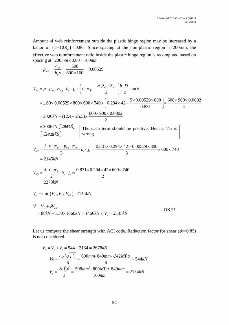
Advanced RC Structures (2017) S. Kono
54
Amount of web reinforcement outside the plastic hinge region may be increased by a
factor of 1 10 0.80pR . Since spacing at the non-plastic region is 200mm, the
effective web reinforcement ratio inside the plastic hinge region is recomputed based on spacing at 200 0.80 160mm mm
00529.0160600
508
sb
ap
e
wwe
1
5tan
2
5 0.00529 800 600 900 0.08021.60 0.00529 800 600 740 0.294 42
0.831 2
600 900 0.08023006 (12.4 25.5)
2
3006 284
we wyu we wy e e B
p b DV p b j
kN
kN kN
2722kN
2
0.831 0.294 42 0.00529 800600 740
3 32145
B we wyu e e
pV b j
kN
3
0.831 0.294 42 600 740
2 22278
Bu e eV b j
kN
1 2 3min , ,u u u uV V V V =2145kN
88 1.30 1060 1466 2145L mu
u
V V V
kN kN kN V kN
OK!!!
Let us compute the shear strength with ACI code. Reduction factor for shear (=0.85) is not considered. 544 2134 2678n c sV V V kN
' 600 840 42
5446 6
w cb d f mm mm MPaVc kN
2508 800 840
2134160
v ys
A f d mm MPa mmV kN
s mm
The each term should be positive. Hence, Vu1 is wrong.

Advanced RC Structures (2017) S. Kono
55
6.2.6.2 Column ( taken from Section 7.1.2 on p. 383 of Ref. 5 ) Compute the shear strength of column shown in Figure 6.19 with the following properties.
950 950b D 835eb mm
835ej mm
Web reinforcement: 4 legs of D13 were set at 100 mm spacing for both plastic hinge region and non-plastic hinge region MPaB 42
01.0pR radian
MPawy 800
(a) Elevation (b) Section
Figure 6.19 Section configuration of a column
2 20 2 20 0.01 1.80pR
01 20 1 20 0.01 0.7 42 / 200 0.8 0.49 0.392pR
100 345
1 1 0.8372 4 2 835 4 835
s
e e
bs
j j
0.9 0.9 950
tan 0.1642 2 2600
D
L
beam (600x900)
column (950x950)
L=2600 mm
je=835 950
950

Advanced RC Structures (2017) S. Kono
56
1
5tan
2
5 0.00608 800 950 950 0.1641.80 0.00608 800 835 835 0.392 42
0.837 2
5172
we wyu we wy e e B
p b DV p b j
kN
2
0.837 0.392 42 0.00608 800835 835 4333
3 3B we wy
u e e
pV b j kN
3
0.837 0.392 42 835 8354804
2 2B
u e eV b j kN
1 2 3min , , 4333u u u uV V V V kN
2 2 2 21.45 1556 1.41 930 2610X mX Y mY uV V V kN V OK!!!
Let us compute the shear strength with ACI code. 924 3658 4582n c sV V V kN
' 950 900 42
9246 6
w cb d f mm mm MPaVc kN
2508 800 900
3658100
v ys
A f d mm MPa mmV kN
s mm

Advanced RC Structures (2017) S. Kono
57
6.3 Design for bond 6.3.1 Code equations 6.3.1.1 Design bond stress Consider design bond stress from the flexural action, f , in Figure 6.21.
Assuming that the bond stress along a single reinforcing bar at the ultimate condition,
f , is constant, the equilibrium for length (L-d) in the axial direction is expressed as
follows.
dLdd
bfb
4
2
(6.23)
Solve the equation for f .
dL
dbf
4
(6.24)
Here, may be computed using the following equation.
2 ( )
( )
2 ( )
yu
yu y
y
Bothends have plastic hinges
Oneend has a plastic hinge
No plastic hingeis planned
(6.25) Bond stress, , for reinforcement of the second layer may be computed using the following equation.
1.5 ( )
0.5 ( )
1.5 ( )
yu
yu y
y
Bothends have plastic hinges
Oneend has a plastic hinge
No plastic hingeis planned
(6.26)
Figure 6.20 Stresses acting on a reinforcing bar
bond stress, τf
L-d
tensile stress, σ1 tensile stress, σ2 difference of tensile stresses on two sides, ⊿σ=σ2 - σ1
db

Advanced RC Structures (2017) S. Kono
58
6.3.1.2 Bond strength Reliable bond strength, bu , is computed with the following equation.
stBitbu kb 11.0086.0 (N/mm2)
(6.27) where t is the strength reduction factor for the top layer reinforcement and expressed
as,
0.75 / 400 Reinforcement in the top layer of beams
1 Other reinforcementB
t
(Unit: N/mm2)
(6.28) and ib is the length ratio of the bond splitting failure and expressed as,
min ,i si cib b b
1
1
bsi
b
b N db
N d
2 cs ct b
cib
d d db
d
(6.29) Now, b is the section width, 1N the number of reinforcing bars in the first layer, csd
the thickness of the side cover, ctd the thickness of the top/bottom cover. The effect of
web reinforcement, stk , is expressed as follows.
1
4756 1
146
wsi w ci si
st
wci si
b
Nb p for b b
Nk
Afor b b
d s
(Unit: N/mm2)
(6.30) where wN is the number of legs of web reinforcement ( 2sN ), wp web
reinforcement ratio, wA the section area of a single reinforcing bar, s the spacing of
web reinforcing bar. Reliable bond strength of the second layer web reinforcement, 2bu , is expressed as,
2222 11.0086.0 stBbitbu kb (N/mm2) (6.31)
22
2
bsi
b
b N db
N d
(6.32)

Advanced RC Structures (2017) S. Kono
59
where 2N is the number of reinforcing bars in the first layer. wsist pbk 1103 22 (N/mm2) (6.33)
Index 2 is supposed to be determined from the bond strength between the first and second layer reinforcement but may be determined from the following equation. 2 0.6 (6.34)) 6.3.2 Effect of bond strength on Shear strength Considering the bond strength, shear capacity, buV , is the minimum of Eq. (6.35) and
Eq. (6.36).
2.5tan
2bu
bu bu e Be
bDV j
b
(6.35)
2
Bbu e eV b j
(6.36) where
1 2 2
1 2 21 10
bu bu
bup bu bu
No plastic hinge possible
R Plastic hinge possible
(6.37)
1 is the sum of peripheral length of the first layer web reinforcing bars, 2 is
that for the second layer. 6.3.3 Design examples 6.3.3.1 Beam (taken from Section 7.2.1 on p. 385 of Ref. 5 ) Compute the bond strength of the beam shown in Figure 6.21(a) with the following properties.
600 1000b D mm mm Web reinforcement: 4 legs of D13 were set at 150 mm spacing for plastic hinge
region, and 200 mm spacing for non-plastic hinge region 48B MPa
400y MPa
1.25 500yu y MPa
5050L mm is the clear span length 915d mm is the effective depth

Advanced RC Structures (2017) S. Kono
60
(a) Elevation (b) Section
Figure 6.21 Section configurations of a beam
First, it was assumed that the beam have plastic hinges at both ends. The design bond stress for the first layer rebars, 1f , is based on 2 2 500yu MPa (Eq. (6.25))
1
38 2 5002.3
4 4 5050 915b
f
dMPa
L d
From Eq. (6.28), 0.75 / 400 0.75 48 / 400 0.87t B
From Eq. (6.29),
1
1
2min , min ,
2 23.5 13 38 / 2 23.5 13 38 / 2 38600 4 38min ,
4 38 38
min 2.947,3.13 2.947
cs ct bbi si ci
b b
d d db N db b b
N d d
From (6.30),
1
47 456 1 56 47 2.947 1 0.00423 1.72
4w
st si w
Nk b p
N
The reliable bond strength, 1bu , is from Eq. (6.27),
154.2
72.14811.0947.2086.087.011.0086.0
f
stBitbu
MPa
kb
Since it is assumed that the beam have plastic hinges at both ends, the design bond stress for the second layer rebars, 2f , is based on 1.5 1.5 500yu MPa
(Eq.(6.26)),
beam (600x1000)
column (950x950)
column (950x950)
L=5050 mm
6000 mm
je=740 1000
600

Advanced RC Structures (2017) S. Kono
61
2
38 1.5 5001.72
4 4 5050 915b
f
dMPa
L d
From (6.32),
22
2
600 4 382.947
4 38b
sib
b N db
N d
From (6.33), 2 2103 1 103 2.947 1 0.00423 16.86st st wk b p
河野,SIでやり直し。 From (6.31),
2 2 2
2
0.0086 0.11
0.6 0.87 0.0086 2.947 0.11 48 16.86
0.522 0.938 16.86
2.17
bu t i B st
f
b k
MPa
6.3.3.2 Column ( taken from Section 7.2.2 on p. 387 of Ref. 5 ) Compute the bond strength of the column shown in Figure 6.22 with the following properties.
950 950b D mm mm Web reinforcement: 4 legs of D13 were set at 80 mm spacing for both plastic
hinge and non-plastic region. 48B MPa
400y MPa
1.25 500yu y MPa
3000L mm is the clear span length 860d mm is the effective depth
First, it is assumed that the beam has a plastic hinge at one end and non-plastic hinge at the other end. The design bond stress for the first layer reinforcement, 1f , is based on
500 400yu y MPa (Eq. (6.25))
1
38 500 4004.0
4 4 3000 860b
f
dMPa
L d
Since reinforcement in the column is under consideration, t is automatically 1 from
Eq. (6.28). 1.0t

Advanced RC Structures (2017) S. Kono
62
(a) Elevation (b) Section
Figure 6.22 Section configuration of a column
From Eq. (6.29)
1
1
2min , min ,
2 90 90 38950 5 38min ,
5 38 38
min 4.0, 5.7 4.0
cs ct bbi si ci
b b
d d db N db b b
N d d
From (6.30),
1
4756 1
456 47 4.0 1 0.00668
5
3.13
wst si w
Nk b p
N
The reliable bond strength, 1bu , is from Eq.(6.27),
1
1
0.086 0.11
1.0 0.086 4.0 0.11 48 3.13
6.27
bu t i B st
f
b k
MPa
beam (600x900)
column (950x950)
L=3000 mm
je=835 950
950

Advanced RC Structures (2017) S. Kono
63
6.4 Design for shear of shearwalls 6.4.1 Shear cracking strength Shear strength of shearwalls can basically be designed using the same except for beams and columns.
scr w wc
w
t lV
(6.38)
2
3
3 1 1 1
4 1 1scr
u u v
u v
(6.39)
'
'w
w
lu
l D
(6.40)
wtvb
(6.41) where wt is the thickness of shearwall, wl the center-center distance between
boundary columns, 'wl the clear span between boundary columns, D the depth of
boundary columns, b the width of boundary columns, 0 the compressive stress of
the shearwall due to vertical load, T tensile strength of concrete and defined by the following equations.
0.313T B (N/mm2)
(6.42) 河野進 図
6.4.2 Shear strength and for a hinge region Shear strength of shearwalls can be expressed as
1cot tan 1
2u w w s sy w wa BV t l p t l
(6.43) where
2
Bs syp
when 2
Bs syp
(6.44) 400sy MPa when 400sy MPa
(6.45)
2
tan 1w w
wa wa
h h
l l

Advanced RC Structures (2017) S. Kono
64
(6.46)
21 cot s sy
B
p
(6.47) cot 1.0
(6.48) where sy is the yield strength of web reinforcement and, wt the thickness of
shearwall, sp the web reinforcement ratio of shearwall, wh the height of shear wall
and may be taken as the story height, the angle of concrete compression strut, and
wal and wbl are the equivalent shearwall depths for truss and arch mechanisms,
respectively. The strength enhancement due to confining effect of boundary columns are taken into account in (6.43) by increasing the effective wall width. The effective width of the shearwall can be expressed as follows for truss and arch mechanisms, respectively. 'wa w wal l D l
(6.49) 'wb w wbl l D l
(6.50) where 'wl is the clear width of shearwall, D is the depth of boundary columns, and
wal and wbl are expressed as:
2
cece w
w
wa ce
wce w
Awhen A t D
t
l A DD
twhen A t D
(6.51)
ce
ce wwwb
ce w
Awhen A t D
tl
D when A t D
(6.52) where ceA is the effective area of boundary columns.
ccce c
B
NA A
3ce wA t D when 3ce wA t D

Advanced RC Structures (2017) S. Kono
65
(6.53) where cA is the area of compression column, ccN is the axial force. When the
effective width for the arch mechanism is computed using (6.49), the shear strength of side column should satisfy the following equation.
2
22
1 tan
2
waa tc
wa
l DV V
l
(6.54) where aV is the shear strength due to the arch mechanism, tan is the angle of arch
mechanism, tcV is the shear strength due to the truss mechanism of the boundary
column. The effective width of the side column is:
cee w
Ab t
D
(6.55) where is the contribution of truss mechanism to the shear strength of shearwall. o for 0.005uR
(6.56) 1.2 40 u oR for 0.005 0.02uR
(6.57) 0.4 o for 0.02 uR
(6.58) where uR is the rotation angle of plastic hinge region.

Advanced RC Structures (2017) S. Kono
66
6.4.3 Design examples 6.4.3.1 Shearwall No. 1 ( taken from Section 7.4 on p. 391 of Ref. 5 ) Long term vertical load 1070 10486LN tf kN
Overturning moment 14430 141414wtM tf m kN m
Additional seismic vertical load coming from the frame transverse to the wall 1070 12564LN tf kN 0.01uR
cot 1.0 249.0 /B N mm
' 7050wl mm
Boundary columns 950cD mm , 816wy kN , 0.00668wp , 770tj mm
Shearwall 300wt mm , 2306 /sy N mm , 0.00663sp ,
Since 0.01uR , 0 0.7 49.0 / 200 0.455
Figure 6.23 Shearwall
beam (600x1000)
column (950x950)
column (950x950) 7050 mm

Advanced RC Structures (2017) S. Kono
67
32
2 2
10486 141414 / 8.0 12564 1.3 10950
49.0
43400 , 0
ccce c
B
ce
NA A
mm hence A mm
Since 2300 950 285000ce wA t D mm ,
0
0.0300
cewa
w
Al mm
t
0
0.0300
cewb
w
Al mm
t
Then, ' 7050 950 0.0 8000wa w wal l D l mm
' 7050 950 0.0 8000wb w wbl l D l mm
2 2
3600 3600tan 1 1 0.647
8000 8000w w
wa wa
h h
l l
1.2 40 1.2 40 0.01 0.455 0.364u oR
20.00663 306 2.03 /s syp N mm and 20.364 49.0 / 2 8.91 /2
B N mm
,
hence 22.03 /s syp N mm
2 21 cot 1 1.0 2.03
0.2280.364 49.0
s sy
B
p
1cot tan 1
2300 8000 2.03 1.0 0.5 0.647 1 0.228 300 8000 0.364 49
4871 10691 15562
u w w s sy w wa BV t l p t l
kN

Advanced RC Structures (2017) S. Kono
68
7 AIJ STANDARD FOR STRUCTURAL CALCULATION OF REINFORCED CONCRETE STRUCTURES, REVISED IN 1991 7.1 Introduction The articles which relate to shear and bond in the AIJ standard (1991) are listed in the following Sections 7.2 and 7.3. Most parts are extracted from the English version of the AIJ standard attached to the “AIJ Structural Design Guidelines for Reinforced Concrete Buildings (1994)”, but some modification of words and expressions were made for this lecture. Also, some private comments were attached. 7.2 Design for Shear As mentioned in the introduction of this lecture note, in earthquake-resistant structures heavy emphasis is placed on ductility. When ductility is essential, the shear failure of structural members must be prevented in any case. In recent years, some theory-based shear design methods have been proposed, like the Nielsen truss analogy and the modified compression field theory by M. P. Collins. However, with respect to the shear problem, it seems too complicated to solve with a simple theory so far. Therefore, the semi-empirical equations proposed by Ohno and Arakawa, which are adopted in the following articles, are still being used. 7.2.1 Art. 16 Shear Reinforcement in Beams and Columns Item 1. Design for shear in a rectangular or T-shaped beam or column shall satisfy the provisions in this article. Design for bond of longitudinal reinforcing bars shall satisfy the provisions of Item 1, Art.17. A member with other sectional shape shall be designed in conformance with the provisions above. If the amount of shear reinforcement provided is confirmed to be sufficient by test or by other method, (1) and (2) in Item 2, and (3) in Item 3 need not be satisfied. Item 2. Beams (1) Allowable shear force AQ of beams shall be calculated by the following formula: )002.0(5.0 wtwsA pffjbQ
(AIJ-22)
where 1
4
dQ
M and 1≦ ≦2
If value of wp is greater than 1.2 percent, allowable shear force shall be calculated
with wp equal to 1.2 percent.
Notation:
b= width of beam or web width for a T-shaped beam

Advanced RC Structures (2017) S. Kono
69
j = distance between compressive and tensile resultants, and may be assumed to be (7/8)d d= effective depth of beam
wp = transverse shear reinforcement ratio = )(/ xbaw
wa = sectional area of a set of transverse shear reinforcement
x = spacing of transverse shear reinforcement
sf = allowable shear stress of concrete
tw f = allowable tensile stress of transverse shear reinforcement
= coefficient as a function of shear span ratio M/Qd M = maximum design bending moment in the beam Q = maximum design shear force in the beam
(2) When bent-up bars are used with stirrups, equivalent reinforcement ratio, wep ,
given by the following equation, may be used in Eq. (AIJ-22) instead of wp , for a
region over j/2 on both sides from the ends of bent-up bars. The contribution of bent-up bars shall be ignored in a member subjected to load reversals.
wtw
twe p
f
f
jb
ap
sin
(AIJ-23) for a set of bent-up bars.
Notation: a = sectional area of a set of bent-up bars = angle of a bent-up bar with respect to the member axis (ordinarily, 45 degrees)
tf = allowable tensile stress of a bent-up bar for shear
(3) Design shear force DQ under the short-term loading shall be calculated by Eq. (24). If design shear force under lateral loading, calculated in accordance with Item 1 in Art. 7, is multiplied by 1.5, Eq. (AIJ-24) need not be used.
'
yLD
MQQ
(AIJ-24)
Notation:
LQ = shear force under the long-term loading
yM = sum of absolute yield moments at both beam ends
' = clear span length of beam.

Advanced RC Structures (2017) S. Kono
70
(4) In addition to the provisions above, shear reinforcement shall be provided to satisfy the following requirements:
1) Size of stirrups shall be not less than φ9 mm for plain bars and not less than D10 for deformed bars, except in the case of light shear reinforcement.
2) Spacing of stirrups shall not exceed (1/2)D nor 25 cm for φ9 mm plain bars or D10 deformed bars, with or without bent-up bars. If larger size bars are used or more effective reinforcement is provided, the spacing may be increased within a limit of (1/2)D and 45 cm.
3) Shear reinforcement ratio shall be not less than 0.2 percent. 4) Stirrups shall enclose tension and compression reinforcing bars, and shall be
arranged to confine the core concrete inside the longitudinal bars. The ends of stirrups shall be anchored by bending more than 135 degrees or the ends shall be welded together.
5) Angle of bent-up bars with the member axis shall be not less than 30 degrees. Item 3. Columns (1) Allowable shear force LAQ of columns for the long-term loading and allowable
shear force SAQ for the short-term loading shall be calculated by the following
equations: sLA fjbQ
)002.0(5.0 wtwsSA pffjbQ
(AIJ-25) where,
1
4
dQ
M and 1≦ ≦2
If the value of wp is greater than 1.2 percent, allowable shear force shall be
calculated with wp equal to 1.2 percent.
Notation:
b = width of column j = distance between tensile and compressive resultants and may be assumed to be (7/8)d d= effective depth of column
wp = transverse shear reinforcement ratio = )(/ xbaw
wa = sectional area of a set of transverse shear reinforcement
x = spacing of transverse shear reinforcement
sf = allowable shear stress of concrete

Advanced RC Structures (2017) S. Kono
71
tw f = allowable tensile stress of transverse shear reinforcement
= coefficient as a function of shear span ratio M/Qd of column M = maximum design bending moment at column end Q = maximum design shear force in the column
(2) Design shear force for the short-term loading shall be a shear force at flexural yielding of the frame that includes the column under consideration. The value may be calculated using Eq. (AIJ-26) if an exact analysis is not performed. If design shear force under lateral loading, calculated in accordance with Item 1 in Art. 7, is multiplied by 1.5, Eq. (AIJ-26) need not be used.
'h
MQ y
D
(AIJ-26) Notation:
yM = sum of absolute yield moments at the top and bottom of a column. If one
half of the sum of yield bending moments of beams connected to the column top is smaller than the yield moment of the column top, the smaller value may be used as the yield bending moment of that column top, except for the case of top story column. For the top of a top-story column, the sum of yield bending moments of beams, instead of half of it, must be compared with the yield moment of the column top. h' = clear height of column
(3) In addition to the above provisions, shear reinforcement shall satisfy the following requirements:
1) Size of a hoop shall be not less than φ9 mm for plain bars and not less than D10 for deformed bars except for the case that spiral reinforcement is used or light shear reinforcement is sufficient.
2) 2)Spacing of hoops shall not exceed 10 cm for φ9 mm plain bars or D10 deformed bars. In a region more than 1.5 times maximum diameter of the column from the top and bottom, the spacing may be increased up to 1.5 times the above limit. If larger size bars are used or more effective reinforcement is provided, the spacing may be increased to 20 cm, appropriately.
3) Shear reinforcement ratio shall be not less than 0.2 percent. 4) Hoops shall enclose longitudinal bars, and shall be arranged to confine the core
concrete inside the longitudinal bars. The ends of hoops shall be anchored by bending more than 135 degrees.
5) When shear force applied to a column likely reaches to a considerably large magnitude, the use of closed-shape hoops, which enclose the longitudinal bars and the ends of which are welded to each other, is desirable to ensure ductile behavior of the column.

Advanced RC Structures (2017) S. Kono
72
----------------------------------------------------------------------------------------------------------- Comments Figure 7.1 and Figure 7.2 show the background data which gave the basis of Eqs. (AIJ-22) and (AIJ-25). The technical term “shear intensity” used for the captions of these figures is defined in Section 4.2 in this lecture note. The plotted data in those figures were obtained from shear tests on about 1,200 beams conducted in Japan and overseas. The size effects of the tested beams were taken into account in the analyses of the test data as shown by the curves in Figure 7.3, in which the abscissa is for the effective depth of beams, d (cm) and the ordinate is for kc (modification factor for cracking shear stress) and ku (modification factor for shear stress at failure). The size effects were referred in Section 4.3.4. When the tension reinforcement ratio, pt = As /bd, is high in the shear span, the widths of flexural shear cracks are narrower at a given load, and this will enable aggregate interlock and dowel actions to carry larger load. The increased strength of the beam action due to larger flexural tension reinforcement has been demonstrated by some tests. This effect has been taken into account in Eq (11-5) in the ACI318-02 code. In the AIJ standard, this effect was neglected as can be seen from Eqs. (AIJ-22) and (AIJ-25), maybe assuming that such effect is negligible, compared with other factors, for a range of pt from about 0.4 to 1 % which is normally used in practical design. When the test data were plotted in Figure 7.2, the effect of the tension reinforcement ratio was eliminated using the modification factor, kp , shown in Figure 7.4. The equivalent reinforcement ratio for a set of bent-up bars in Eq. (AIJ-23) was derived from the geometry of the bent-up bars with the assumed 45 degree cracks shown in Figure 7.5. In Figure 7.5, the spacing and the inclination of bent up bars are denoted by x’ and , respectively. Also, the tension stress on the potential cracked surface is denoted by in the figure. The derivation of Eq. (AIJ-23) can be seen in the commentary of the original AIJ standard (1991). A similar exercise has been conducted in Section 4.3.5 ( see Figure 4.14). The notation of ΣMy for Eq. (AIJ-26) is illustrated in Figure 7.6. It was assumed that the beams connected to the bottom end of the column will unlikely yield because the section size of those beams would be larger than that of the beams connected to the top end of the column. However, it is noted that, when a frame is designed so as to achieve the total yield mechanism (= beam side-sway mechanism) shown in Fig. C 3.2 in the AIJ Structural Design Guidelines, such assumption is not conservative. -----------------------------------------------------------------------------------------------------------

Advanced RC Structures (2017) S. Kono
73
Figure 7.1 Relationship between Shear Stress Intensity at Shear Cracking and M/Qd
Figure 7.2 Relationship between Shear Stress Intensity at Shear Failure and M/Qd

Advanced RC Structures (2017) S. Kono
74
Figure 7.3 Size Effects on Shear Strength
Figure 7.4 Effects of Tension Reinforcement Ratio on Shear Strength
Figure 7.5 Geometry to Determine Equivalent Reinforcement Ratio for Bent-up Bars, pwe
Figure 7.6 Design Shear Force for Columns

Advanced RC Structures (2017) S. Kono
75
7.3 Design for Development, Anchorage and Lap Splices Art. 17 Bond, Anchorage and Lap Splices Item 1. Bond (1) Bond stress, a , along a tensile reinforcing bar in a flexural member due to shear
shall be calculated by Eq. (AIJ-27), except when the provisions of Clause (2) are satisfied.
aa fj
Q
(AIJ-27) Notation:
Q = design shear force; design shear for the short-term loading shall conform to (3) of Item 2 in Art. 16 or (2) of Item 3 in Art. 16 j = distance between tensile and compressive resultants of a flexural section and may be assumed to be (7/8)d = sum of perimeter of tensile reinforcing bars
af = allowable bond stress (see Table 6, Art. 6).
(2) Distance, dl , from critical section of tensile reinforcement in a flexural member to
the end of the reinforcement in a span shall be calculated by Eq. (AIJ-28), except when the provisions in Clause (1) is satisfied (see Fig. 11).
jf
al
a
td
8.0
(AIJ-28) Notation:
dl = distance from critical section to the end of a reinforcing bar
t = tensile stress of a reinforcing bar at the critical section, the value may be
reduced to two thirds if the bar is hooked at the end a = sectional area of a reinforcing bar = perimeter of a reinforcing bar
af = allowable bond stress and values in Table 6, Art. 6
j = distance between tensile and compressive resultants of a section in a flexural member, and may be assumed to be (7/8)d

Advanced RC Structures (2017) S. Kono
76
Item 2. Anchorage and lap splices (1) Development length of a longitudinal bar in a beam-column joint or length of a lap splice shall be calculated by Eq. (AIJ-29).
a
td f
al
(AIJ-29) Notation:
dl = development length or length of a lap splice, excluding the length of a hook
t = maximum stress in an anchor part or at a lap splice, but value shall, in
ordinary cases, be allowable stress for a lap splice. The value may be reduced to two-thirds if a bar is hooked at the end a = sectional area of a reinforcing bar
af = allowable bond stress for top reinforcement, as specified in Table 6 in Art. 6
irrespective of position of the bar. The value may be increased by 1.5 times if the stress of reinforcement is compression, or if a deformed bar is anchored in a beam-column connection where bond split cracking is not anticipated, and = perimeter of a reinforcing bar
(2) A lap splice shall, in general, be located at a region where both the member stress and reinforcement stress are small. (3) Minimum anchor length and lap splice length shall be as specified in Table 10. The development length of bottom reinforcement in a floor slab and roof slab in a connection may be 15 cm for a plain bar with hook, and 10 d and 15 cm for a deformed bar for all steel grades and for all design standard strength and types of concrete. Anchor length of bottom reinforcement in a floor beam into a connection shall be 25d with hook for a plain bar, and 25d or 15d with hook for all steel grades and for all design standard strength and types of concrete. (4) Plain bars of not less than 28 mm diameter and deformed bars not less than size D29 shall not be lap-spliced. (5) A reinforcing bar shall be hooked at the ends. Deformed bars may not be hooked at the ends except in the following cases: a) Corners of columns and beams, except in foundation beams b) Chimneys. Inside radius of a hook and of a bend shall conform to the provisions of "JASS 5." (6) In a lap splice of welded wire mesh, the lap length between end transverse wires shall be not less than the sum of spacing of transverse wires and 5 cm nor less than 15 cm.
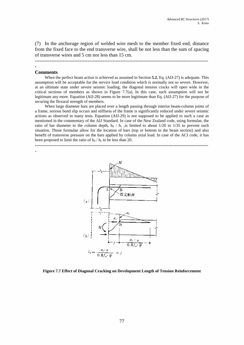
Advanced RC Structures (2017) S. Kono
77
(7) In the anchorage region of welded wire mesh to the member fixed end, distance from the fixed face to the end transverse wire, shall be not less than the sum of spacing of transverse wires and 5 cm nor less than 15 cm. ---------------------------------------------------------------------------------------------------------- Comments When the perfect beam action is achieved as assumed in Section 5.2, Eq. (AIJ-27) is adequate. This assumption will be acceptable for the service load condition which is normally not so severe. However, at an ultimate state under severe seismic loading, the diagonal tension cracks will open wide in the critical sections of members as shown in Figure 7.7(a). In this case, such assumption will not be legitimate any more. Equation (AIJ-28) seems to be more legitimate than Eq. (AIJ-27) for the purpose of securing the flexural strength of members. When large diameter bars are placed over a length passing through interior beam-column joints of a frame, serious bond slip occurs and stiffness of the frame is significantly reduced under severe seismic actions as observed in many tests. Equation (AIJ-29) is not supposed to be applied to such a case as mentioned in the commentary of the AIJ Standard. In case of the New Zealand code, using formulae, the ratio of bar diameter to the column depth, bd / hc ,is limited to about 1/20 to 1/35 to prevent such situation. Those formulae allow for the location of bars (top or bottom in the beam section) and also benefit of transverse pressure on the bars applied by column axial load. In case of the ACI code, it has been proposed to limit the ratio of bd / hc to be less than 20. ----------------------------------------------------------------------------------------------------------
Figure 7.7 Effect of Diagonal Cracking on Development Length of Tension Reinforcement

Advanced RC Structures (2017) S. Kono
78
8 SHEAR DESIGN OF RC MEMBERS BASED ON ‘DESIGN GUIDELINES FOR EARTHQUAKE RESISTANT REINFORCED CONCRETE BUILDINGS BASED ON ULTIMATE STRENGTH CONCEPT’ (1991) 8.1 Plastic theory 8.1.1 The lower bound theorem If the load has such a magnitude that it is possible to find a stress distribution corresponding to stresses within the yield surface and satisfying the equilibrium condition and the statistical boundary conditions for the actual load, then this load will not be able to cause collapse of the body. 8.1.2 The upper bound theorem If various geometrically possible strain fields are considered, the work equation can be used to find values of the load carrying capacity that are greater than or equal to the true one. 8.2 Scope
1. Ensure that the reliable shear strength is large than design shear when the failure mechanism is reached
2. Ensure that the deformation capacity at the plastic hinge. 3. Prevent a bond splitting failure.
8.3 Shear strength of beams and columns Shear strength can be expressed with the following equation. Use
2B
wywp
when 2
Bwywp
.
2
1tancot B
wywtu
DbpjbV
(8.1) where
D
L
D
L
1tan
2
(8.2) and
B
wywp
2cot1.
(8.3) Based on the lower bound theorem in Limit analysis by Nielsen Equilibrium with respect to the shear force Plastic criteria shear rebar reached yielding Concrete strut reached its effective strength B Longitudinal rebar is assumed infinitely strong.
Truss action
Arch action

Advanced RC Structures (2017) S. Kono
79
8.3.1 The first term (contribution from the truss action)
Figure 8.1 Truss mechanism
The equilibrium of the free body in the vertical direction is, sincos ttct jbV
(8.4) Since the vertical components of forces in diagonal strut and the stirrup need to be same. wywjttc pxbxb sinsin
(8.5)
wywwyw
tc pp
22
cot1sin
(8.6) Hence we have
cot
sincossin 2
twyw
twyw
t
jbp
jbp
V

Advanced RC Structures (2017) S. Kono
80
(8.7) 8.3.2 The second term (contribution from the arch action)
Figure 8.2 Arch mechanism
After truss mechanism takes up tc out of B which is the compressive capacity
of concrete strut, tcB can be used for the arch action. Neglecting the angle of
truss and arch,
tan2
12
tan2
2
Db
D
L
D
LDb
DbV
tcB
ac
aca
(8.8) 8.3.3 Integration of the truss and arch actions
tan2
1cot
tan2
1cot
tan2
cot
Dbpjb
Dbpjb
Dbpjb
VVV
Bwywt
B
tcBwywt
tcBwywt
atu
(8.9) Truss action
Arch action

Advanced RC Structures (2017) S. Kono
81
Figure 8.3 General characteristics of design equation
The value of cot is the minimum of
2cot (implies that 6.26 ) (8.10)
tan
cot
D
jt (this gives the maximum Vu)
(8.11)
1cot
wyw
B
p
( Btc in the truss mechanism)
(8.12) 8.3.4 Coefficients for members without plastic hinges
200
7.0 Bo
( B is in MPa)
(8.13)

Advanced RC Structures (2017) S. Kono
82
8.3.5 Coefficients for members with plastic hinges Assume that pR denotes the rotational angle at the yield hinge, then the
effectiveness factor can be expressed by the following two equations or Figure 8.4. opR 150.1 for 05.00 pR
(8.14) o 25.0 for 05.0pR
(8.15)
Figure 8.4 Relationship between the guaranteed hinge rotation Rp and
The value of cot is the minimum of the following four equations. The first two equations are shown in Figure 8.5. pR500.2cot for 02.00 pR
(8.16) 0.1cot for pR02.0
(8.17)
tan
cot
D
jt (SAME as EQ. (8.11))
(8.18)
1cot
wyw
B
p
(SAME as EQ. (8.12))
(8.19)
Figure 8.5 Relationship between the guaranteed hinge rotation Rp and cot

Advanced RC Structures (2017) S. Kono
83
8.3.6 Minimum reinforcement 0.2% for all beams and columns 8.4 Shear strength of walls 8.4.1 Shear strength Basically the same except
1. yf should be smaller than 400 MPa.
2. 0.1cot
3. and o have been set especially for the wall
4. Column size is taken into account for arch action. 5. Shear is check for each story and hence the method assuring the shear transfer
between stories is provided. 8.4.2 Equivalent wall widths Equivalent wall widths are different for truss action and arch action. 8.4.3 Effective factor of concrete for a non-hinge region Eq. (8.13)) in Section 8.3.4 can be used. 8.4.4 Effective factor of concrete for a hinge region o for 005.0pR
(8.20) opR 402.1 for 02.0005.0 pR
(8.21) o 4.0 for pR02.0
(8.22)
Figure 8.6 Effectiveness factor of concrete, vm, and deformation capacity

Advanced RC Structures (2017) S. Kono
84
8.4.5 Beam between stories A fraction of shear carried by the arch mechanism of the upper story is directly transferred to the arch mechanism of the lower story. The rest of the shear carried by the arch mechanism of the upper story needs to be transferred to the lower story through the tensile action of beams or the truss mechanism in the lower story. 8.4.6 Minimum reinforcement 0.25% for walls. 0.3% for plastic hinge region of the boundary columns. 8.5 Bond 8.5.1 Design bond stress
f from a flexural action
dLdd
bfb
4
2
(8.23)
dL
dbf
4
(8.24)
2
2
yu
yu y
y
(8.25)
t from a truss mechanism
xT t
(8.26)
xj
V
j
MT
t
t
t
(Perfect beam action was assumed.)
(8.27)
cot cott w wy w wyt
tt t
b j p b pV
j j
(8.28) 8.5.2 Bond strength
Bb
wbu d
p
52.1
(8.29) Bond strength for the top reinforcement of a beam shall be reduced to 0.8 times the value in Eq. (8.29)).

Advanced RC Structures (2017) S. Kono
85
REFERENCES 1. Park, R. and Paulay Thomas, Reinforced Concrete Structures, John Wiley & Sons,
1975. 2. James G. MacGregor, Reinforced Concrete Mechanics and Design, Prentice Hall,
1988. 3. AIJ structural design guidelines for reinforced concrete buildings based on ultimate
strength concept (Japanese), Architecture Institute of Japan, 1990. 4. AIJ structural design guidelines for reinforced concrete buildings based on ultimate
strength concept (English), Architecture Institute of Japan, 1994. 5. AIJ structural design guidelines for reinforced concrete buildings based on inelastic
displacement concept (Japanese), Architecture Institute of Japan, 1997. 6. 渡邉史夫,窪田敏行:エース建築工学シリーズ エース 鉄筋コンクリート
構造,朝倉書店,2003年. 7. 林静雄,北山和宏,衣笠秀行,坂田弘安:建築家のための鉄筋コンクリート
構造,市ヶ谷出版社,2007年. ACKNOWLEDGEMENT The class note on shear and bond was originally compiled by Professor Emeritus Hitoshi Tanaka of the Disaster Prevention Research Institute, Kyoto University, as a lecture note for the International Institute of Seismology and Earthquake Engineering, Building Research Institute. The content was modified and a chapter on flexure was added later. Design equations of shear strength was also added from the AIJ structural design guidelines for reinforced concrete buildings based on inelastic displacement concept.
HOW TO REACH ME Susumu KONO
Professor Institute of Innovative Research Tokyo Institute of Technology Nagatsuta 4259, G5-1 Midori, Yokohama, 226-8503, Japan Tel/Fax: +81-45-924-5384 Email: [email protected] WWW: http://www.msl.titech.ac.jp/~serc/kono/