Embed Size (px)
Citation preview
RECIPROCATING COMPRESSOR PERFORMANCE IMPROVEMENT
WITH RADIAL POPPET VALVES
2009 GMRC Gas Machinery Conference – Atlanta, GA – October 5‐7, 2009
Lauren D. Sperry, PE & W. Norman Shade, PE ACI Services Inc.
ABSTRACT Over the past decade, radial compressor valves and unloaders have been successfully introduced into reciprocating compressors for the gas transmission industry. The unique radial valve system seats multiple rows of poppets over ports in a cylindrical sleeve that replaces the traditional cage and single‐deck valve used in a reciprocating compressor. The radial valve concept has been applied for both suction and discharge valves in a broad range of compressor models and pipeline cylinder classes. Use of these valves has resulted in significant increases in efficiency and reductions in HP/MMSCFD. For cylinder end deactivation, the cylindrical valve guard is moved to slide the poppets off their seats and away from the ports, providing a relatively unobstructed flow path for the gas. The resulting parasitic losses of the deactivated cylinder end approach the losses achieved by complete removal of a traditional valve. Use of radial valves has also been found to significantly increase unit capacity. Some of this increase stems from being able to operate the more efficient radial valved compressor with less unloading, so that there is more effective displacement utilized for the same power input. Moreover, in practice the significant added fixed volumetric clearance inherent in the radial poppet valves has not reduced the measured volumetric efficiency or the capacity as much as traditional theory would predict. This paper will present four case studies that show the actual field operating performance improvements obtained with radial poppet valves on both low speed and high speed compressors, along with laboratory test comparisons, and an explanation of why the capacity can increase even though the fixed clearance increases. INTRODUCTION The best single‐deck valves are limited to about 30% to 35% open flow area. This type of valve has the benefit of lowest possible fixed volumetric clearance, which is sometimes an advantage; however the limited flow area can significantly limit its efficiency, especially in high flow, low pressure ratio applications. Conventional valves have historically utilized poppets, concentric rings, ported plates, or metal reeds as the sealing elements in a round seat and guard assembly or “deck” that spans the round ports or pockets of the compressor cylinder.
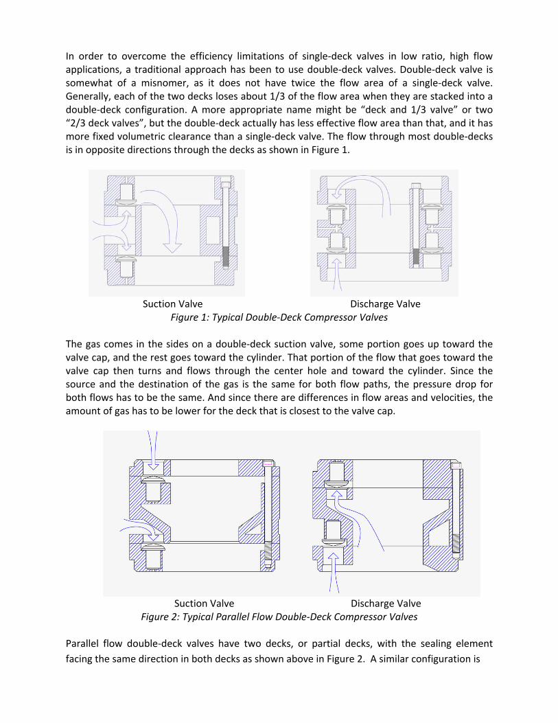
In order to overcome the efficiency limitations of single‐deck valves in low ratio, high flow applications, a traditional approach has been to use double‐deck valves. Double‐deck valve is somewhat of a misnomer, as it does not have twice the flow area of a single‐deck valve. Generally, each of the two decks loses about 1/3 of the flow area when they are stacked into a double‐deck configuration. A more appropriate name might be “deck and 1/3 valve” or two “2/3 deck valves”, but the double‐deck actually has less effective flow area than that, and it has more fixed volumetric clearance than a single‐deck valve. The flow through most double‐decks is in opposite directions through the decks as shown in Figure 1.
Suction Valve Discharge Valve
Figure 1: Typical Double‐Deck Compressor Valves The gas comes in the sides on a double‐deck suction valve, some portion goes up toward the valve cap, and the rest goes toward the cylinder. That portion of the flow that goes toward the valve cap then turns and flows through the center hole and toward the cylinder. Since the source and the destination of the gas is the same for both flow paths, the pressure drop for both flows has to be the same. And since there are differences in flow areas and velocities, the amount of gas has to be lower for the deck that is closest to the valve cap.
Suction Valve Discharge Valve Figure 2: Typical Parallel Flow Double‐Deck Compressor Valves
Parallel flow double‐deck valves have two decks, or partial decks, with the sealing element facing the same direction in both decks as shown above in Figure 2. A similar configuration is
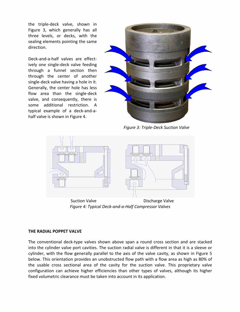
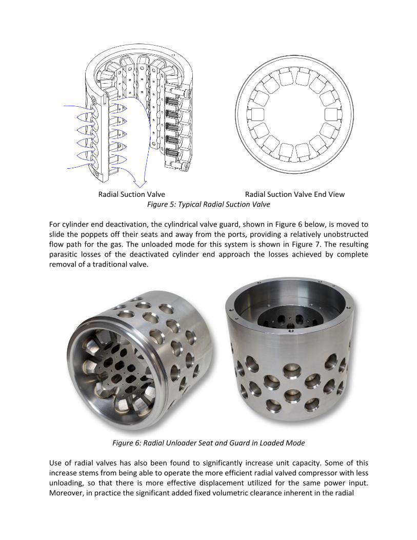
the triple‐deck valve, shown in Figure 3, which generally has all three levels, or decks, with the sealing elements pointing the same direction. Deck‐and‐a‐half valves are effect‐ively one single‐deck valve feeding through a funnel section then through the center of another single‐deck valve having a hole in it. Generally, the center hole has less flow area than the single‐deck valve, and consequently, there is some additional restriction. A typical example of a deck‐and‐a‐half valve is shown in Figure 4. Figure 3: Triple‐Deck Suction Valve
Suction Valve Discharge Valve
Figure 4: Typical Deck‐and‐a‐Half Compressor Valves
THE RADIAL POPPET VALVE
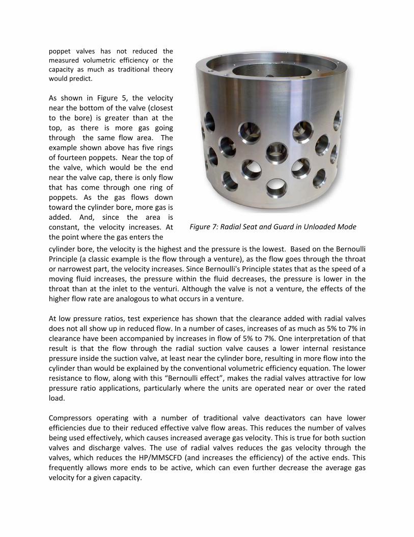
The conventional deck‐type valves shown above span a round cross section and are stacked into the cylinder valve port cavities. The suction radial valve is different in that it is a sleeve or cylinder, with the flow generally parallel to the axis of the valve cavity, as shown in Figure 5 below. This orientation provides an unobstructed flow path with a flow area as high as 80% of the usable cross sectional area of the cavity for the suction valve. This proprietary valve configuration can achieve higher efficiencies than other types of valves, although its higher fixed volumetric clearance must be taken into account in its application.
Radial Suction Valve Radial Suction Valve End View
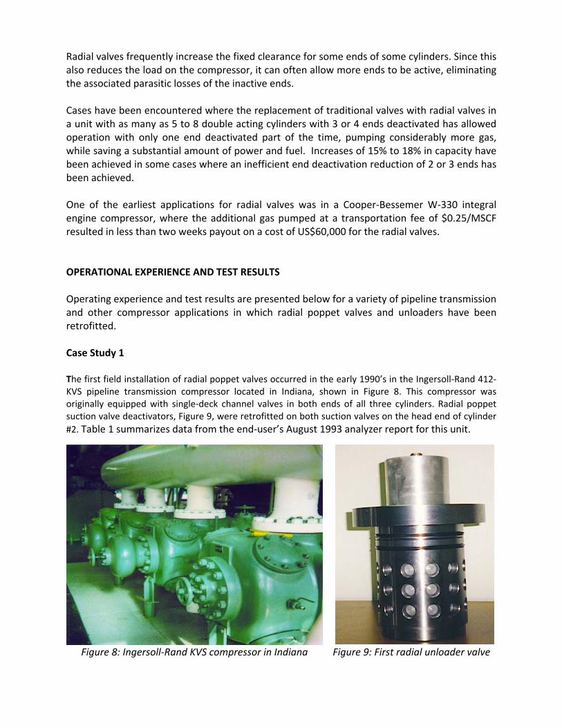
Figure 5: Typical Radial Suction Valve For cylinder end deactivation, the cylindrical valve guard, shown in Figure 6 below, is moved to slide the poppets off their seats and away from the ports, providing a relatively unobstructed flow path for the gas. The unloaded mode for this system is shown in Figure 7. The resulting parasitic losses of the deactivated cylinder end approach the losses achieved by complete removal of a traditional valve.
Figure 6: Radial Unloader Seat and Guard in Loaded Mode
Use of radial valves has also been found to significantly increase unit capacity. Some of this increase stems from being able to operate the more efficient radial valved compressor with less unloading, so that there is more effective displacement utilized for the same power input. Moreover, in practice the significant added fixed volumetric clearance inherent in the radial
poppet valves has not reduced the measured volumetric efficiency or the capacity as much as traditional theory would predict. As shown in Figure 5, the velocity near the bottom of the valve (closest to the bore) is greater than at the top, as there is more gas going through the same flow area. The example shown above has five rings of fourteen poppets. Near the top of the valve, which would be the end near the valve cap, there is only flow that has come through one ring of poppets. As the gas flows down toward the cylinder bore, more gas is added. And, since the area is constant, the velocity increases. At the point where the gas enters the
Figure 7: Radial Seat and Guard in Unloaded Mode
cylinder bore, the velocity is the highest and the pressure is the lowest. Based on the Bernoulli Principle (a classic example is the flow through a venture), as the flow goes through the throat or narrowest part, the velocity increases. Since Bernoulli's Principle states that as the speed of a moving fluid increases, the pressure within the fluid decreases, the pressure is lower in the throat than at the inlet to the venturi. Although the valve is not a venture, the effects of the higher flow rate are analogous to what occurs in a venture. At low pressure ratios, test experience has shown that the clearance added with radial valves does not all show up in reduced flow. In a number of cases, increases of as much as 5% to 7% in clearance have been accompanied by increases in flow of 5% to 7%. One interpretation of that result is that the flow through the radial suction valve causes a lower internal resistance pressure inside the suction valve, at least near the cylinder bore, resulting in more flow into the cylinder than would be explained by the conventional volumetric efficiency equation. The lower resistance to flow, along with this “Bernoulli effect”, makes the radial valves attractive for low pressure ratio applications, particularly where the units are operated near or over the rated load. Compressors operating with a number of traditional valve deactivators can have lower efficiencies due to their reduced effective valve flow areas. This reduces the number of valves being used effectively, which causes increased average gas velocity. This is true for both suction valves and discharge valves. The use of radial valves reduces the gas velocity through the valves, which reduces the HP/MMSCFD (and increases the efficiency) of the active ends. This frequently allows more ends to be active, which can even further decrease the average gas velocity for a given capacity.
Radial valves frequently increase the fixed clearance for some ends of some cylinders. Since this also reduces the load on the compressor, it can often allow more ends to be active, eliminating the associated parasitic losses of the inactive ends. Cases have been encountered where the replacement of traditional valves with radial valves in a unit with as many as 5 to 8 double acting cylinders with 3 or 4 ends deactivated has allowed operation with only one end deactivated part of the time, pumping considerably more gas, while saving a substantial amount of power and fuel. Increases of 15% to 18% in capacity have been achieved in some cases where an inefficient end deactivation reduction of 2 or 3 ends has been achieved. One of the earliest applications for radial valves was in a Cooper‐Bessemer W‐330 integral engine compressor, where the additional gas pumped at a transportation fee of $0.25/MSCF resulted in less than two weeks payout on a cost of US$60,000 for the radial valves. OPERATIONAL EXPERIENCE AND TEST RESULTS Operating experience and test results are presented below for a variety of pipeline transmission and other compressor applications in which radial poppet valves and unloaders have been retrofitted. Case Study 1 The first field installation of radial poppet valves occurred in the early 1990’s in the Ingersoll‐Rand 412‐KVS pipeline transmission compressor located in Indiana, shown in Figure 8. This compressor was originally equipped with single‐deck channel valves in both ends of all three cylinders. Radial poppet suction valve deactivators, Figure 9, were retrofitted on both suction valves on the head end of cylinder #2. Table 1 summarizes data from the end‐user’s August 1993 analyzer report for this unit.
Figure 8: Ingersoll‐Rand KVS compressor in Indiana Figure 9: First radial unloader valve
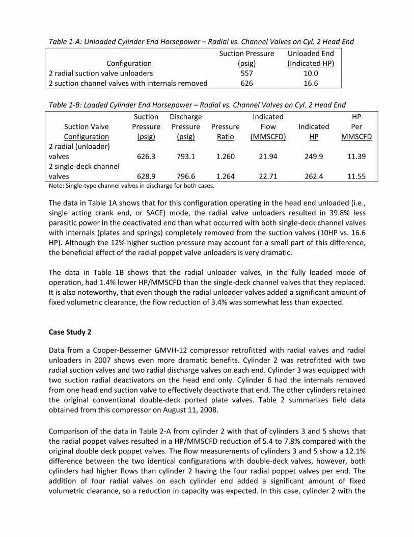
Table 1‐A: Unloaded Cylinder End Horsepower – Radial vs. Channel Valves on Cyl. 2 Head End
Configuration
Suction Pressure (psig)
Unloaded End (Indicated HP)
2 radial suction valve unloaders 557 10.0 2 suction channel valves with internals removed 626 16.6 Table 1‐B: Loaded Cylinder End Horsepower – Radial vs. Channel Valves on Cyl. 2 Head End
Suction Valve Configuration
Suction Pressure (psig)
Discharge Pressure (psig)
PressureRatio
Indicated Flow
(MMSCFD)
Indicated
HP
HP Per
MMSCFD 2 radial (unloader) valves
626.3
793.1
1.260
21.94
249.9
11.39
2 single‐deck channel valves
628.9
796.6
1.264
22.71
262.4
11.55
Note: Single‐type channel valves in discharge for both cases.
The data in Table 1A shows that for this configuration operating in the head end unloaded (i.e., single acting crank end, or SACE) mode, the radial valve unloaders resulted in 39.8% less parasitic power in the deactivated end than what occurred with both single‐deck channel valves with internals (plates and springs) completely removed from the suction valves (10HP vs. 16.6 HP). Although the 12% higher suction pressure may account for a small part of this difference, the beneficial effect of the radial poppet valve unloaders is very dramatic. The data in Table 1B shows that the radial unloader valves, in the fully loaded mode of operation, had 1.4% lower HP/MMSCFD than the single‐deck channel valves that they replaced. It is also noteworthy, that even though the radial unloader valves added a significant amount of fixed volumetric clearance, the flow reduction of 3.4% was somewhat less than expected. Case Study 2
Data from a Cooper‐Bessemer GMVH‐12 compressor retrofitted with radial valves and radial unloaders in 2007 shows even more dramatic benefits. Cylinder 2 was retrofitted with two radial suction valves and two radial discharge valves on each end. Cylinder 3 was equipped with two suction radial deactivators on the head end only. Cylinder 6 had the internals removed from one head end suction valve to effectively deactivate that end. The other cylinders retained the original conventional double‐deck ported plate valves. Table 2 summarizes field data obtained from this compressor on August 11, 2008. Comparison of the data in Table 2‐A from cylinder 2 with that of cylinders 3 and 5 shows that the radial poppet valves resulted in a HP/MMSCFD reduction of 5.4 to 7.8% compared with the original double deck poppet valves. The flow measurements of cylinders 3 and 5 show a 12.1% difference between the two identical configurations with double‐deck valves, however, both cylinders had higher flows than cylinder 2 having the four radial poppet valves per end. The addition of four radial valves on each cylinder end added a significant amount of fixed volumetric clearance, so a reduction in capacity was expected. In this case, cylinder 2 with the
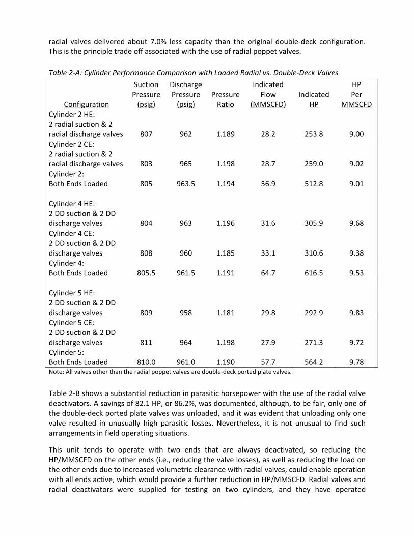
radial valves delivered about 7.0% less capacity than the original double‐deck configuration. This is the principle trade off associated with the use of radial poppet valves. Table 2‐A: Cylinder Performance Comparison with Loaded Radial vs. Double‐Deck Valves
Configuration
Suction Pressure (psig)
Discharge Pressure (psig)
PressureRatio
Indicated Flow
(MMSCFD)
Indicated
HP
HP Per
MMSCFD Cylinder 2 HE: 2 radial suction & 2 radial discharge valves
807
962
1.189
28.2
253.8
9.00 Cylinder 2 CE: 2 radial suction & 2 radial discharge valves
803
965
1.198
28.7
259.0
9.02 Cylinder 2: Both Ends Loaded
805
963.5
1.194
56.9
512.8
9.01
Cylinder 4 HE: 2 DD suction & 2 DD discharge valves
804
963
1.196
31.6
305.9
9.68 Cylinder 4 CE: 2 DD suction & 2 DD discharge valves
808
960
1.185
33.1
310.6
9.38 Cylinder 4: Both Ends Loaded
805.5
961.5
1.191
64.7
616.5
9.53
Cylinder 5 HE: 2 DD suction & 2 DD discharge valves
809
958
1.181
29.8
292.9
9.83 Cylinder 5 CE: 2 DD suction & 2 DD discharge valves
811
964
1.198
27.9
271.3
9.72 Cylinder 5: Both Ends Loaded
810.0
961.0
1.190
57.7
564.2
9.78
Note: All valves other than the radial poppet valves are double‐deck ported plate valves.
Table 2‐B shows a substantial reduction in parasitic horsepower with the use of the radial valve deactivators. A savings of 82.1 HP, or 86.2%, was documented, although, to be fair, only one of the double‐deck ported plate valves was unloaded, and it was evident that unloading only one valve resulted in unusually high parasitic losses. Nevertheless, it is not unusual to find such arrangements in field operating situations.
This unit tends to operate with two ends that are always deactivated, so reducing the HP/MMSCFD on the other ends (i.e., reducing the valve losses), as well as reducing the load on the other ends due to increased volumetric clearance with radial valves, could enable operation with all ends active, which would provide a further reduction in HP/MMSCFD. Radial valves and radial deactivators were supplied for testing on two cylinders, and they have operated
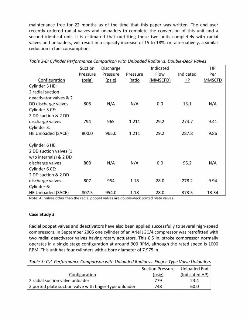
maintenance free for 22 months as of the time that this paper was written. The end user recently ordered radial valves and unloaders to complete the conversion of this unit and a second identical unit. It is estimated that outfitting these two units completely with radial valves and unloaders, will result in a capacity increase of 15 to 18%, or, alternatively, a similar reduction in fuel consumption. Table 2‐B: Cylinder Performance Comparison with Unloaded Radial vs. Double‐Deck Valves
Configuration
Suction Pressure (psig)
Discharge Pressure (psig)
PressureRatio
Indicated Flow
(MMSCFD)
Indicated
HP
HP Per
MMSCFD Cylinder 3 HE: 2 radial suction deactivator valves & 2 DD discharge valves
806
N/A
N/A
0.0
13.1
N/A Cylinder 3 CE: 2 DD suction & 2 DD discharge valves
794
965
1.211
29.2
274.7
9.41 Cylinder 3: HE Unloaded (SACE)
800.0
965.0
1.211
29.2
287.8
9.86
Cylinder 6 HE: 2 DD suction valves (1 w/o internals) & 2 DD discharge valves
808
N/A
N/A
0.0
95.2
N/A Cylinder 6 CE: 2 DD suction & 2 DD discharge valves
807
954
1.18
28.0
278.2
9.94 Cylinder 6: HE Unloaded (SACE)
807.5
954.0
1.18
28.0
373.5
13.34
Note: All valves other than the radial poppet valves are double‐deck ported plate valves.
Case Study 3 Radial poppet valves and deactivators have also been applied successfully to several high‐speed compressors. In September 2005 one cylinder of an Ariel JGC/4 compressor was retrofitted with two radial deactivator valves having rotary actuators. This 6.5 in. stroke compressor normally operates in a single stage configuration at around 900 RPM, although the rated speed is 1000 RPM. This unit has four cylinders with a bore diameter of 7.975 in. Table 3: Cyl. Performance Comparison with Unloaded Radial vs. Finger‐Type Valve Unloaders
Configuration
Suction Pressure (psig)
Unloaded End(Indicated HP)
2 radial suction valve unloader 779 23.4 2 ported plate suction valve with finger‐type unloader 748 60.0
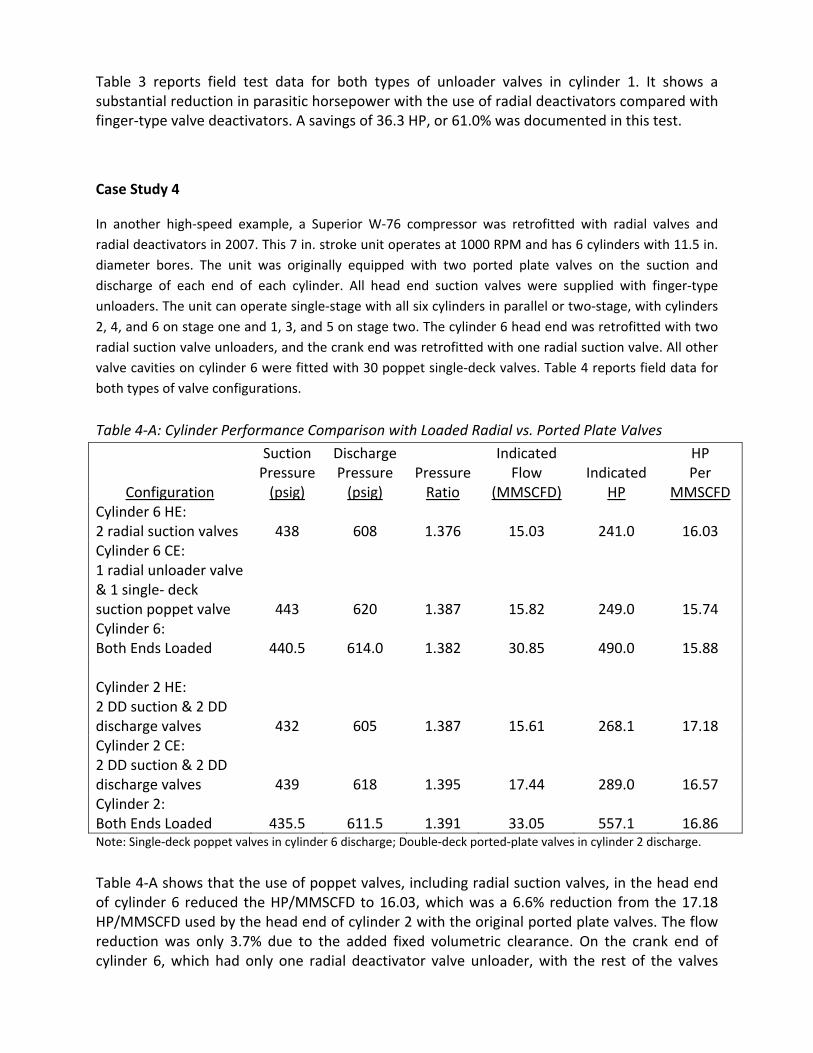
Table 3 reports field test data for both types of unloader valves in cylinder 1. It shows a substantial reduction in parasitic horsepower with the use of radial deactivators compared with finger‐type valve deactivators. A savings of 36.3 HP, or 61.0% was documented in this test.
Case Study 4
In another high‐speed example, a Superior W‐76 compressor was retrofitted with radial valves and radial deactivators in 2007. This 7 in. stroke unit operates at 1000 RPM and has 6 cylinders with 11.5 in. diameter bores. The unit was originally equipped with two ported plate valves on the suction and discharge of each end of each cylinder. All head end suction valves were supplied with finger‐type unloaders. The unit can operate single‐stage with all six cylinders in parallel or two‐stage, with cylinders 2, 4, and 6 on stage one and 1, 3, and 5 on stage two. The cylinder 6 head end was retrofitted with two radial suction valve unloaders, and the crank end was retrofitted with one radial suction valve. All other valve cavities on cylinder 6 were fitted with 30 poppet single‐deck valves. Table 4 reports field data for both types of valve configurations.
Table 4‐A: Cylinder Performance Comparison with Loaded Radial vs. Ported Plate Valves
Configuration
Suction Pressure (psig)
Discharge Pressure (psig)
PressureRatio
Indicated Flow
(MMSCFD)
Indicated
HP
HP Per
MMSCFD Cylinder 6 HE: 2 radial suction valves
438
608
1.376
15.03
241.0
16.03
Cylinder 6 CE: 1 radial unloader valve & 1 single‐ deck suction poppet valve
443
620
1.387
15.82
249.0
15.74 Cylinder 6: Both Ends Loaded
440.5
614.0
1.382
30.85
490.0
15.88
Cylinder 2 HE: 2 DD suction & 2 DD discharge valves
432
605
1.387
15.61
268.1
17.18 Cylinder 2 CE: 2 DD suction & 2 DD discharge valves
439
618
1.395
17.44
289.0
16.57 Cylinder 2: Both Ends Loaded
435.5
611.5
1.391
33.05
557.1
16.86
Note: Single‐deck poppet valves in cylinder 6 discharge; Double‐deck ported‐plate valves in cylinder 2 discharge.
Table 4‐A shows that the use of poppet valves, including radial suction valves, in the head end of cylinder 6 reduced the HP/MMSCFD to 16.03, which was a 6.6% reduction from the 17.18 HP/MMSCFD used by the head end of cylinder 2 with the original ported plate valves. The flow reduction was only 3.7% due to the added fixed volumetric clearance. On the crank end of cylinder 6, which had only one radial deactivator valve unloader, with the rest of the valves
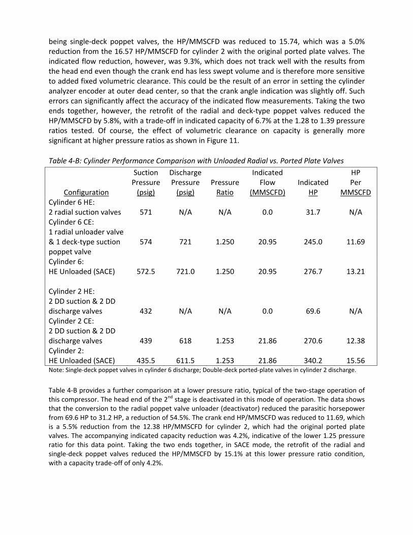
being single‐deck poppet valves, the HP/MMSCFD was reduced to 15.74, which was a 5.0% reduction from the 16.57 HP/MMSCFD for cylinder 2 with the original ported plate valves. The indicated flow reduction, however, was 9.3%, which does not track well with the results from the head end even though the crank end has less swept volume and is therefore more sensitive to added fixed volumetric clearance. This could be the result of an error in setting the cylinder analyzer encoder at outer dead center, so that the crank angle indication was slightly off. Such errors can significantly affect the accuracy of the indicated flow measurements. Taking the two ends together, however, the retrofit of the radial and deck‐type poppet valves reduced the HP/MMSCFD by 5.8%, with a trade‐off in indicated capacity of 6.7% at the 1.28 to 1.39 pressure ratios tested. Of course, the effect of volumetric clearance on capacity is generally more significant at higher pressure ratios as shown in Figure 11.
Table 4‐B: Cylinder Performance Comparison with Unloaded Radial vs. Ported Plate Valves
Configuration
Suction Pressure (psig)
Discharge Pressure (psig)
PressureRatio
Indicated Flow
(MMSCFD)
Indicated
HP
HP Per
MMSCFD Cylinder 6 HE: 2 radial suction valves
571
N/A
N/A
0.0
31.7
N/A
Cylinder 6 CE: 1 radial unloader valve & 1 deck‐type suction poppet valve
574
721
1.250
20.95
245.0
11.69
Cylinder 6: HE Unloaded (SACE)
572.5
721.0
1.250
20.95
276.7
13.21
Cylinder 2 HE: 2 DD suction & 2 DD discharge valves
432
N/A
N/A
0.0
69.6
N/A Cylinder 2 CE: 2 DD suction & 2 DD discharge valves
439
618
1.253
21.86
270.6
12.38 Cylinder 2: HE Unloaded (SACE)
435.5
611.5
1.253
21.86
340.2
15.56
Note: Single‐deck poppet valves in cylinder 6 discharge; Double‐deck ported‐plate valves in cylinder 2 discharge.
Table 4‐B provides a further comparison at a lower pressure ratio, typical of the two‐stage operation of this compressor. The head end of the 2nd stage is deactivated in this mode of operation. The data shows that the conversion to the radial poppet valve unloader (deactivator) reduced the parasitic horsepower from 69.6 HP to 31.2 HP, a reduction of 54.5%. The crank end HP/MMSCFD was reduced to 11.69, which is a 5.5% reduction from the 12.38 HP/MMSCFD for cylinder 2, which had the original ported plate valves. The accompanying indicated capacity reduction was 4.2%, indicative of the lower 1.25 pressure ratio for this data point. Taking the two ends together, in SACE mode, the retrofit of the radial and single‐deck poppet valves reduced the HP/MMSCFD by 15.1% at this lower pressure ratio condition, with a capacity trade‐off of only 4.2%.
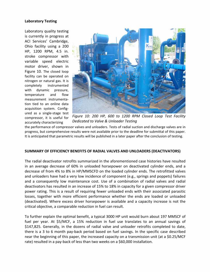
Laboratory Testing Laboratory quality testing is currently in progress at ACI Services’ Cambridge, Ohio facility using a 200 HP, 1200 RPM, 4.5 in. stroke compressor with variable speed electric motor driver, shown in Figure 10. The closed loop facility can be operated on nitrogen or natural gas. It is completely instrumented with dynamic pressure, temperature and flow measurement instrumenta‐tion tied to an online data acquisition system. Config‐ured as a single‐stage test compressor, it is useful for accurately characterizing
Figure 10: 200 HP, 600 to 1200 RPM Closed Loop Test Facility Dedicated to Valve & Unloader Testing
the performance of compressor valves and unloaders. Tests of radial suction and discharge valves are in progress, but comprehensive results were not available prior to the deadline for submittal of this paper. It is anticipated that parametric results will be published in a later paper after the conclusion of testing. SUMMARY OF EFFICIENCY BENEFITS OF RADIAL VALVES AND UNLOADERS (DEACTIVATORS) The radial deactivator retrofits summarized in the aforementioned case histories have resulted in an average decrease of 60% in unloaded horsepower on deactivated cylinder ends, and a decrease of from 4% to 8% in HP/MMSCFD on the loaded cylinder ends. The retrofitted valves and unloaders have had a very low incidence of component (e.g., springs and poppets) failures and a consequently low maintenance cost. Use of a combination of radial valves and radial deactivators has resulted in an increase of 15% to 18% in capacity for a given compressor driver power rating. This is a result of requiring fewer unloaded ends with their associated parasitic losses, together with more efficient performance whether the ends are loaded or unloaded (deactivated). Where excess driver horsepower is available and a capacity increase is not the critical objective, a comparable reduction in fuel can result. To further explain the optimal benefit, a typical 3000 HP unit would burn about 197 MMSCF of fuel per year. At $5/MCF, a 15% reduction in fuel use translates to an annual savings of $147,825. Generally, in the dozens of radial valve and unloader retrofits completed to date, there is a 3 to 6 month pay‐back period based on fuel savings. In the specific case described near the beginning of this paper, the increased capacity on a transmission unit (at a $0.25/MCF rate) resulted in a pay‐back of less than two weeks on a $60,000 installation.
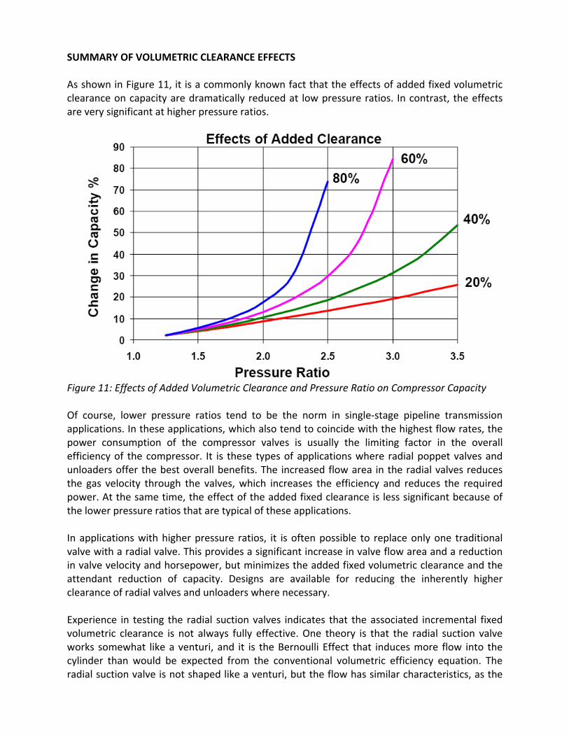
SUMMARY OF VOLUMETRIC CLEARANCE EFFECTS As shown in Figure 11, it is a commonly known fact that the effects of added fixed volumetric clearance on capacity are dramatically reduced at low pressure ratios. In contrast, the effects are very significant at higher pressure ratios.
Figure 11: Effects of Added Volumetric Clearance and Pressure Ratio on Compressor Capacity Of course, lower pressure ratios tend to be the norm in single‐stage pipeline transmission applications. In these applications, which also tend to coincide with the highest flow rates, the power consumption of the compressor valves is usually the limiting factor in the overall efficiency of the compressor. It is these types of applications where radial poppet valves and unloaders offer the best overall benefits. The increased flow area in the radial valves reduces the gas velocity through the valves, which increases the efficiency and reduces the required power. At the same time, the effect of the added fixed clearance is less significant because of the lower pressure ratios that are typical of these applications. In applications with higher pressure ratios, it is often possible to replace only one traditional valve with a radial valve. This provides a significant increase in valve flow area and a reduction in valve velocity and horsepower, but minimizes the added fixed volumetric clearance and the attendant reduction of capacity. Designs are available for reducing the inherently higher clearance of radial valves and unloaders where necessary. Experience in testing the radial suction valves indicates that the associated incremental fixed volumetric clearance is not always fully effective. One theory is that the radial suction valve works somewhat like a venturi, and it is the Bernoulli Effect that induces more flow into the cylinder than would be expected from the conventional volumetric efficiency equation. The radial suction valve is not shaped like a venturi, but the flow has similar characteristics, as the
flow, and consequently the velocity, increases over the distance from the valve cap toward the cylinder bore. This is analogous to the flow through a venturi, where the velocity increases to a maximum at the throat. The high velocity point corresponds to a low static pressure point, which may allow higher flow into the cylinder than would otherwise be expected. This increased flow phenomenon decreases with increased pressure ratio. Further research, including CFD modeling and laboratory‐quality testing is planned in the near future in order to characterize this effect in more detail. It is anticipated that the results of these investigations will be reported in a future paper. CLOSURE The application of more than 250 radial poppet valves and unloaders to date has demonstrated significant benefits in performance and reliability with both low‐speed and high‐speed pipeline transmission compressors. Although it is not practical in this brief summary to provide all of the pertinent technical details, it is important to recognize that the actual performance improvement that is achievable with radial valves and/or radial valve unloaders (deactivators) is dependent on many factors, including: o Compressor pressure ratio o Original valve flow area or lift area o Flow area or lift area possible with the radial valves (considering the geometric limitations of existing cylinder ports)
o Volumetric clearance added by the radial valves and/or unloaders o Compressor speed and stroke (piston speed) o Cylinder passage area and geometry around the valve ports o Cylinder muff area and geometry from the valve ports to the cylinder main flanges. o Cylinder suction and discharge nozzle area The authors would like to thank the numerous unnamed end users who have contributed to the successful introduction of radial valves and unloaders by providing test installations and field performance data. REFERENCES 1. Sperry, Lauren D., Significant Efficiency Gains with Radial Valves and Unloaders, GMC
Journal, May 2009. 2. Radial Unloader Valve Designed for Changing Compressor Operating Conditions and Practices,
CompressorTechTwo, October‐November 2004.