Embed Size (px)
Citation preview
RCD Revit Modeling Guidelines, Version 1, July 15, 2009 (Copyright 2009) 1 of 80
Reed Construction Data (RCD)
Revit Modeling Guidelines 1.0
Table of Contents Page
1. Overview ………………………………………………………….. 1 - 2
2. Family Files and Templates …………………………………….. 2
3. System Families ………………………………………………….. 2
4. Determining the Amount of Detail to Include in the Model..…. 3 - 4
5. Candidates for Nonparametric Models..……………………….. 4
6. Candidates for Parametric Models …………………………….. 4 - 5
7. Naming Conventions …………………………………………… 5 - 42
8. Tutorials ………………………………………………………… 43
9. Step By Step Example …………………………………………. 43 - 53
10. Modeling Techniques ………………………………………….. 54 - 79
11. Appendix A – Scope of Project - Data Sheet …………………. 80
1. Overview This document is designed to document RCD standards for modeling, to provide guidelines on techniques, and to show through example the considerations that need to be part of the creation of excellent objects (Revit Family Files, RFAs or “.rfa” files) and assemblies (Revit System Families).
This document is not a tutorial on how to model Revit Family files and System Families; it is assumed that the user of this document has experience and expertise in these areas. There are good tutorials (see Section 8) included within the standard Revit installation and from other sources if the reader needs this fundamental knowledge.
The modeling of Revit objects (such as doors, windows, and appliances) and Revit assemblies (such as walls, floors and ceilings) is both an art and a science.
The science component refers to the familiarity and proficiency that the modeler has of the Revit interface, tools and methods which allow the creation of parametric and or
RCD Revit Modeling Guidelines, Version 1, July 15, 2009 (Copyright 2009) 2 of 80
complex geometry. The Revit toolset is very powerful; it allows the creation of curved, blended and extruded solids and voids. Moreover, it also allows creation of types which are preset dimensional variants of a particular family (a door model with preset dimensions such as 3’0”x6’8”, 3’2”x6’8”, 3’4”x6’8”, etc.). Also Revit enables models to bind data so that families are able to be scheduled with pertinent information including colors and materials in addition to traditional sizes and model numbers.
The art component deals with making decisions on how the object should be modeled, what amount of detail should be included in the model, and how the parametric functions should be designed and implemented.
RCD has studied the creation of objects and assemblies for both modeling and the attachment and association of data. This document provides guidelines on how to efficiently develop high quality objects and assemblies in Revit.
2. Family Files and Templates Examples of Revit objects (Family Files) are models of doors, windows or furniture. Revit has over 40 categories of Family Files and many of these categories have predefined templates to help the modeler start the process of creating an object. When starting a model take some time to become familiar with the different templates and begin with the appropriate template.
In developing a Revit Family, a modeler can create any number of parameters or create relationships with floors, walls or ceilings. However, among certain types of families many of these features will be the same. For example, doors will always be hosted within walls and will have certain parameters common to most if not all doors. To expedite such family development, templates were created by Revit so that one will have many of these parameters already created and the model is already prebuilt to the point that it is hosted with a wall. You will see that the Door template has parameters already set for Frame Width, Frame Projection Interior and Frame Projection Exterior and has an opening in a generic wall.
3. System Families Revit assemblies or System Families are families that exist only within the context of a Revit Project (.RVT file). Some examples are stairs, railings, floors, ceilings, walls and so on. These families have predetermined behaviors (a roof can be sloped or flat) and optionally can have material definitions (shingles, building paper, sheathing, joists, insulation, and gypsum board). The modeler creates assemblies by selecting the appropriate type of assembly, modeling it within the context of the project and optionally, defining the materials.
RCD Revit Modeling Guidelines, Version 1, July 15, 2009 (Copyright 2009) 3 of 80
4. Determining the Amount of Detail to Include in the Family File Model
Two similar looking models can be very different when reviewed in detail. The differences may determine if the model is of value to the customer. There are several considerations.
a. How the model will look in the Revit project – Designers care how the model will look in their project. Small differences in trim, mullions, reveals, and curves are very important to a designer. They will select one manufacturer’s product over another based upon small differences, they then want to see their selection correctly represented in the project. At the same time Revit is a tool for creating contract documents. There is a balance between good graphical representations for rendering, good graphical representations for drafting and the contribution of the model to the project file size. See “b”.
b. How the model will perform in the Revit project – Object models that are created with unnecessary parameters, features, or complexity will tend to be large in file size. Revit houses a project in a single file and as Objects are added to the project, the project file size grows and performance of the model decreases due to hardware and memory limitations. It is possible to create a project file so large that it can no longer be worked upon. Therefore an object modeler must weigh functionality (parametrics) and graphical integrity against building a smaller model that compromises on these features.
c. Modeling Considerations – Do not model detail that will not be seen in any view. For example, if a window has stiffeners in the extrusion and snap together connections that cannot be seen, eliminate this from the model. Do not model screws and bolts. When possible, use a more simple technique to represent an object rather than creating its more complicated equivalent. For example, in a louvered door – you could model each louver, represent the width, thickness and length as well as angle and array them into a section of the door. This will create a large file that will be slow to respond to modifications as Revit will take time to process the necessary adjustments every time the door is resized. The other option is creating a graphical representation of the louver edges using a model line that give a simple representation of the presence of the louvers. In most instances, this is all that will be required in the context of a building model. On the other hand a manufacturer may desire to have the louvers actually modeled.
d. How the model will render – Designers will render their Revit projects for both presentations and internal design studies. Test your models to insure that they render properly. Some considerations will be material maps, material transparency and colors assigned to the model as well as geometric correctness. Insure that you cannot see through parts and pieces of the model. For example, if you have two materials over lapping each other the top piece must have a thickness of greater than 1/16” (even if in reality the material is thinner) or the
RCD Revit Modeling Guidelines, Version 1, July 15, 2009 (Copyright 2009) 4 of 80
lower piece may “bleed through” the upper piece, you will need to experiment to make sure the product looks correct.
5. Candidates for Nonparametric Models When possible, object models should be created parametrically so that they can be reused (See Section 6 below).
In some cases nonparametric models are the only logical option, for example:
a. Only one version, such as an Eames chair or plumbing fixtures
b. Curved geometry with changes in the x,y and z coordinates, such as a toilet.
c. Where exact dimensions are not critical, such as a weight machine that might be 5’6” tall or 6’; where these differences in height most likely makes no difference to the designer or the project.
6. Candidates for Parametric Models Creating parametric models is the preferred approach to modeling. Parametric models can take considerably longer to create than nonparametric models. However, once the parametric model is created it is much more valuable than the nonparametric model. Our goal is to be known as the premier modeler of Revit objects so it is to our long term value to create excellent parametric models. Ideal candidates for parametric models are doors, windows, cabinets, furniture, systems furniture, skylights, basically all products that come in multiple sizes but with the same basic geometry.
Once the decision has been made to create a parametric model the investigation into the best way to model must be undertaken. Most objects that will be modeled parametrically have multiple variables as well as multiple parts and pieces. For example, a double hung window can have the following variables:
a. height, width and depth
b. location in the wall (outside edge, centered, inside edge, any other location)
c. trim on exterior (no trim or trim of any size)
d. interior trim on interior (no trim or trim of any size)
e. mullions on interior of glass, on exterior of glass, between the glass (any combination)
f. spacing and number of the mullions
g. mullions on only one of the two sashes
h. materials and colors
RCD Revit Modeling Guidelines, Version 1, July 15, 2009 (Copyright 2009) 5 of 80
i. Strings of windows creating an assembly.
The modeler will need to determine if all variables should be accommodated in one model or if several models should be created and if sub assemblies should be used. Once a preliminary model is created it must be tested for usability which includes size of model, download time, and parametric change time once inserted into the model. You will find that at times that when the model is tested you will need to reevaluate your approach. While this may seem complicated the result of this process will be an excellent model that will be much appreciated by the customer.
In this document you will find a step by step example of the process and decisions that were taken to create a casement window. (See Step by Step Example)
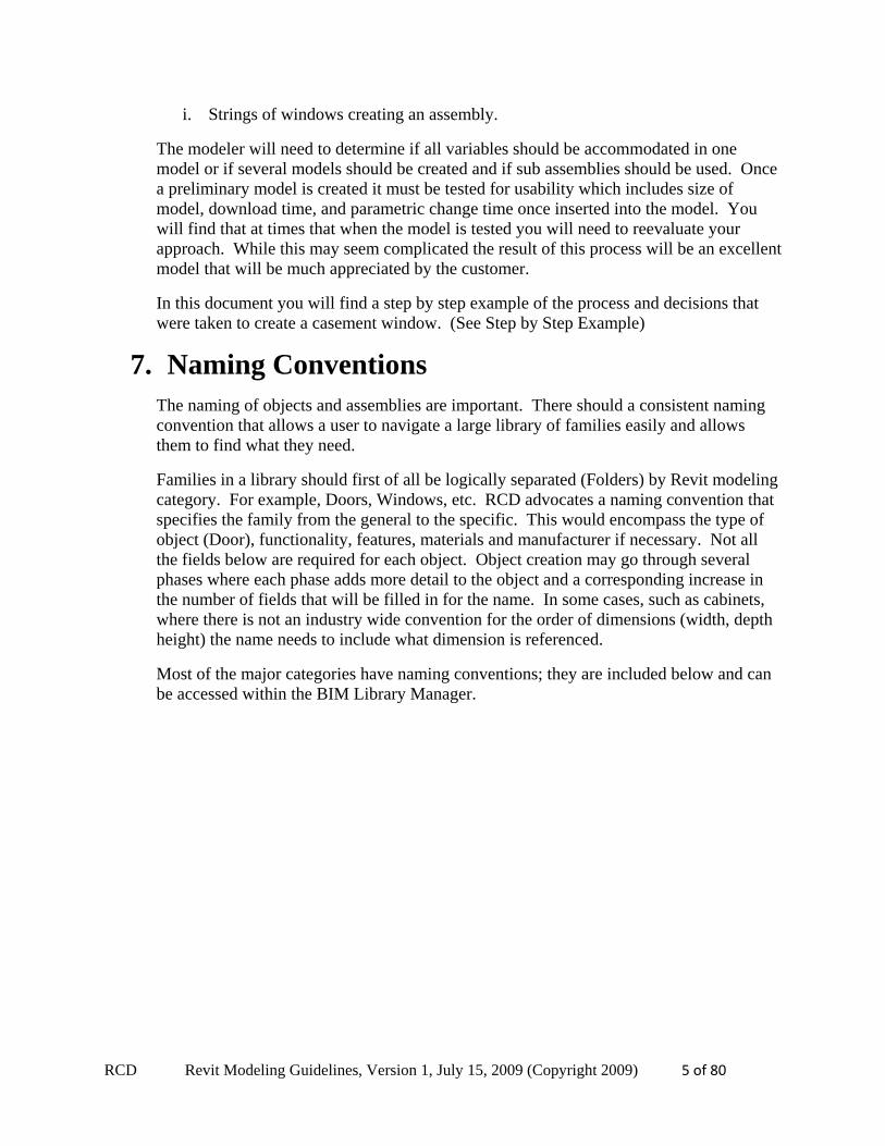
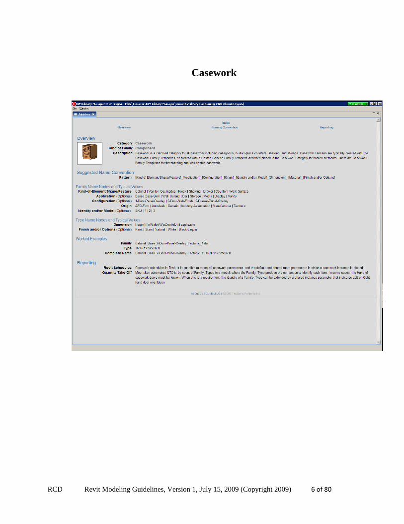
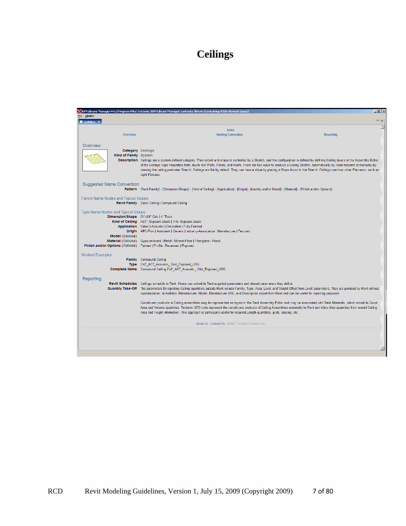
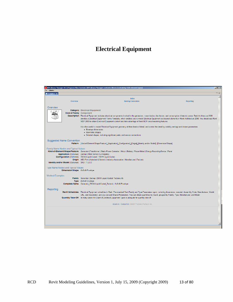
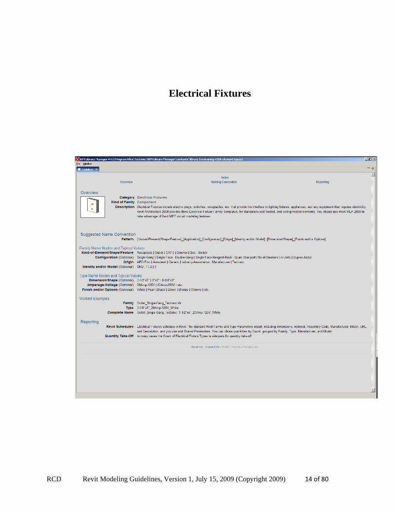
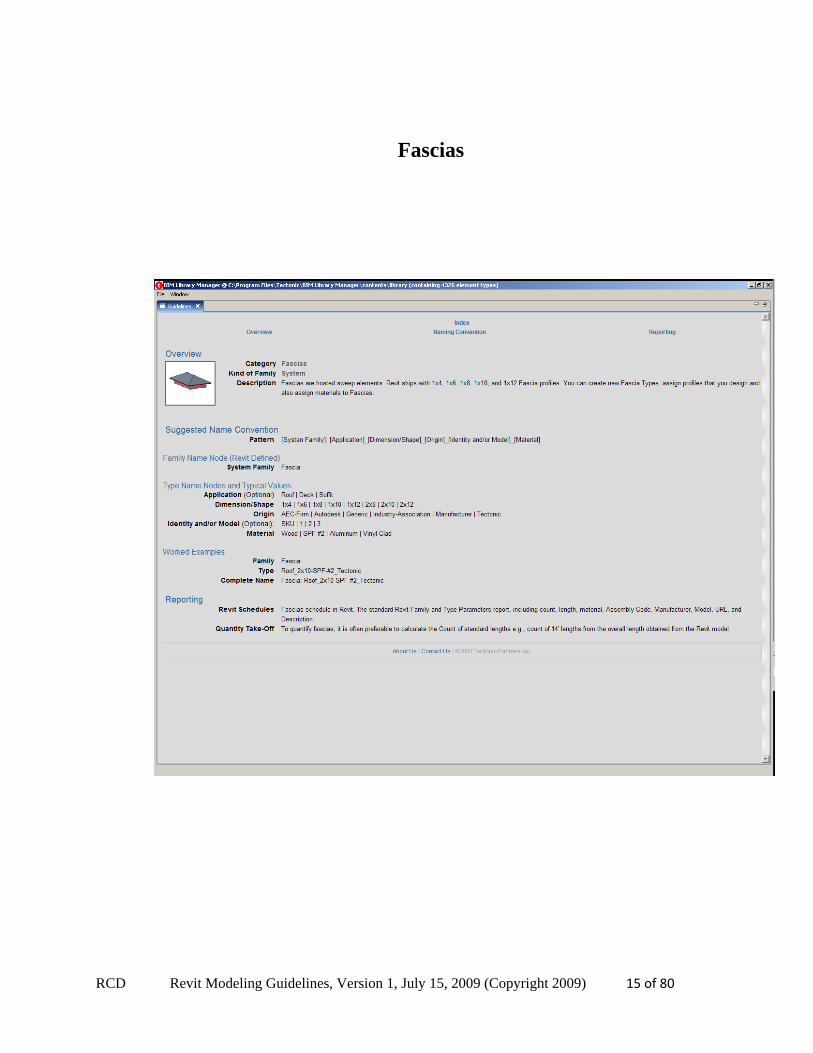
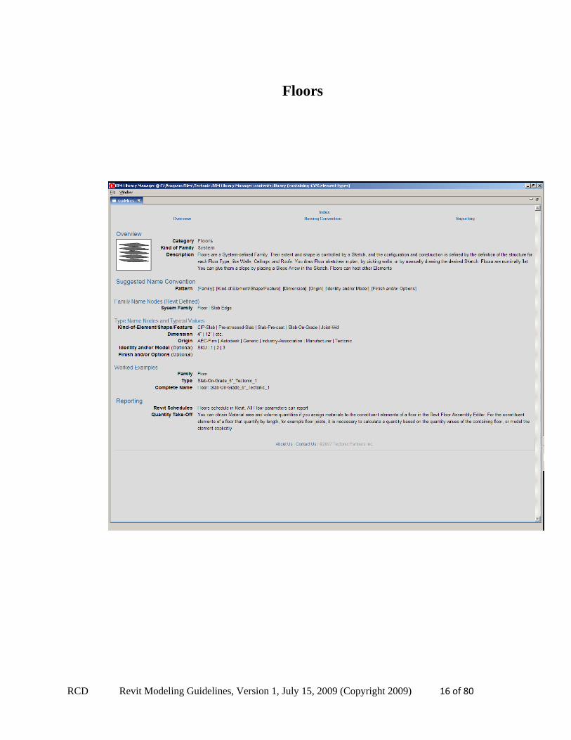
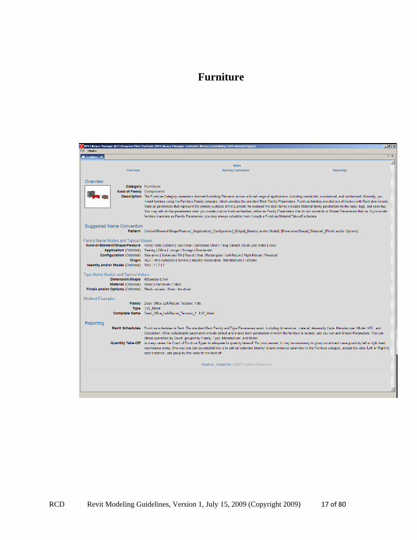
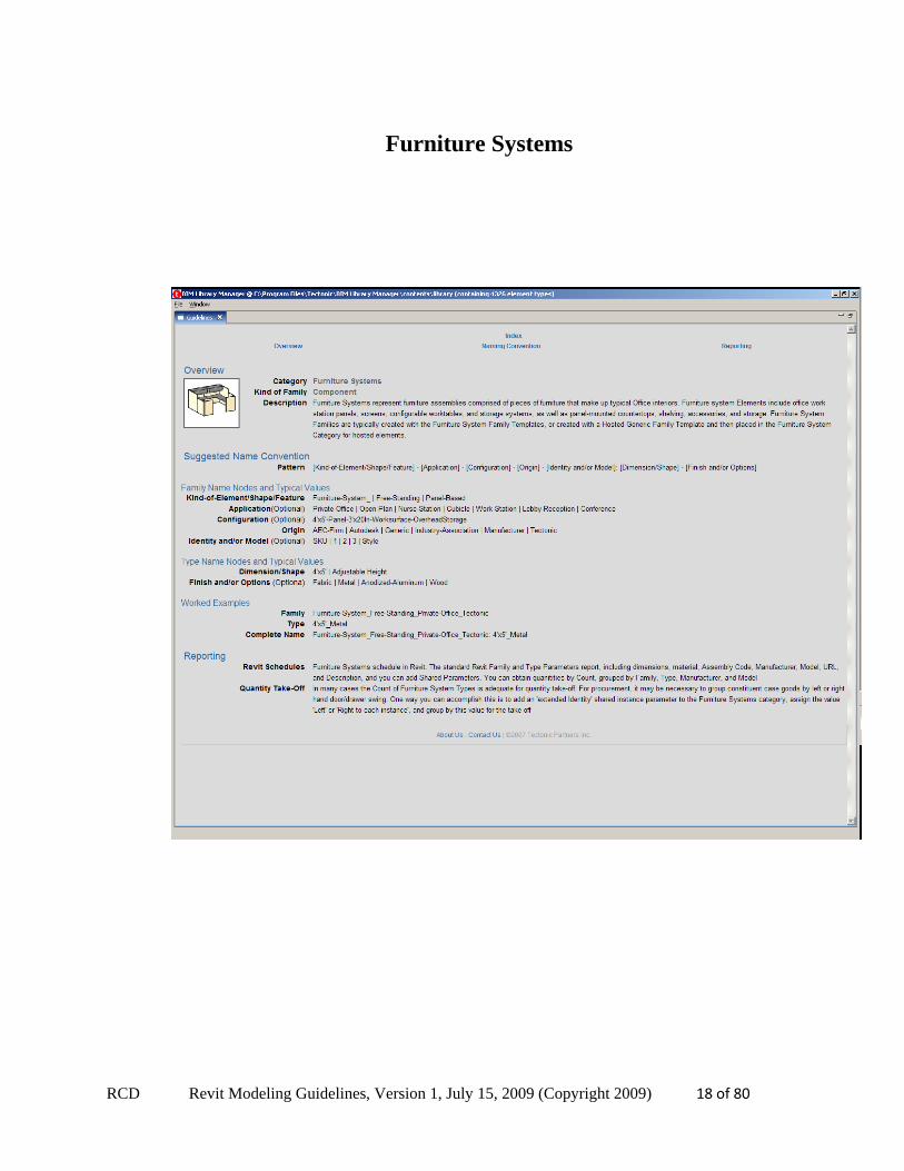
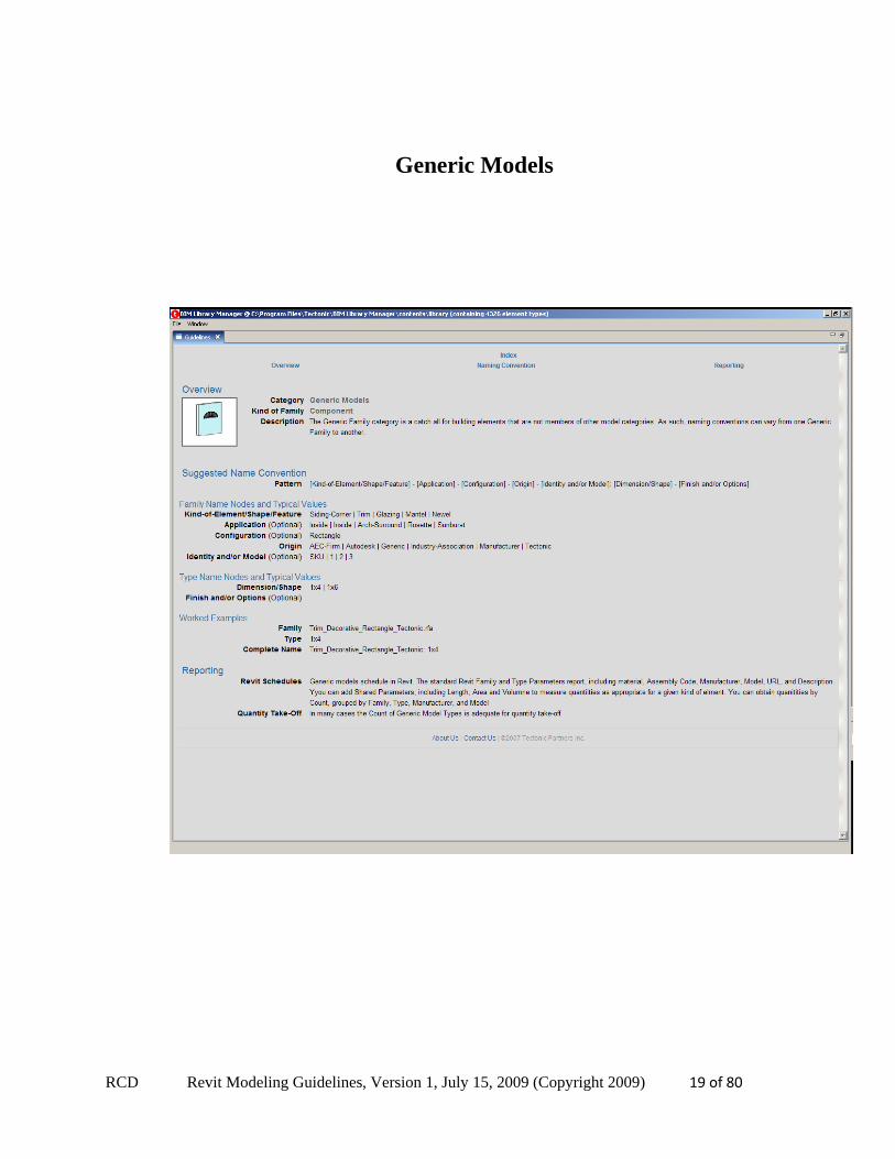
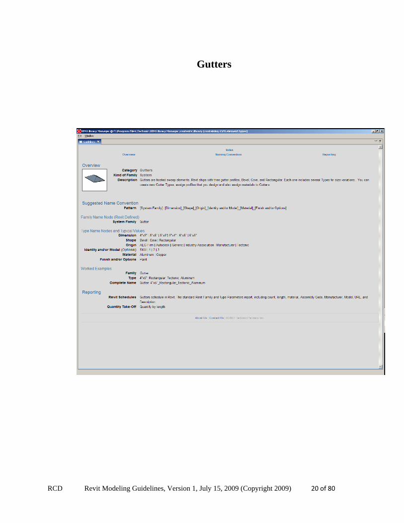
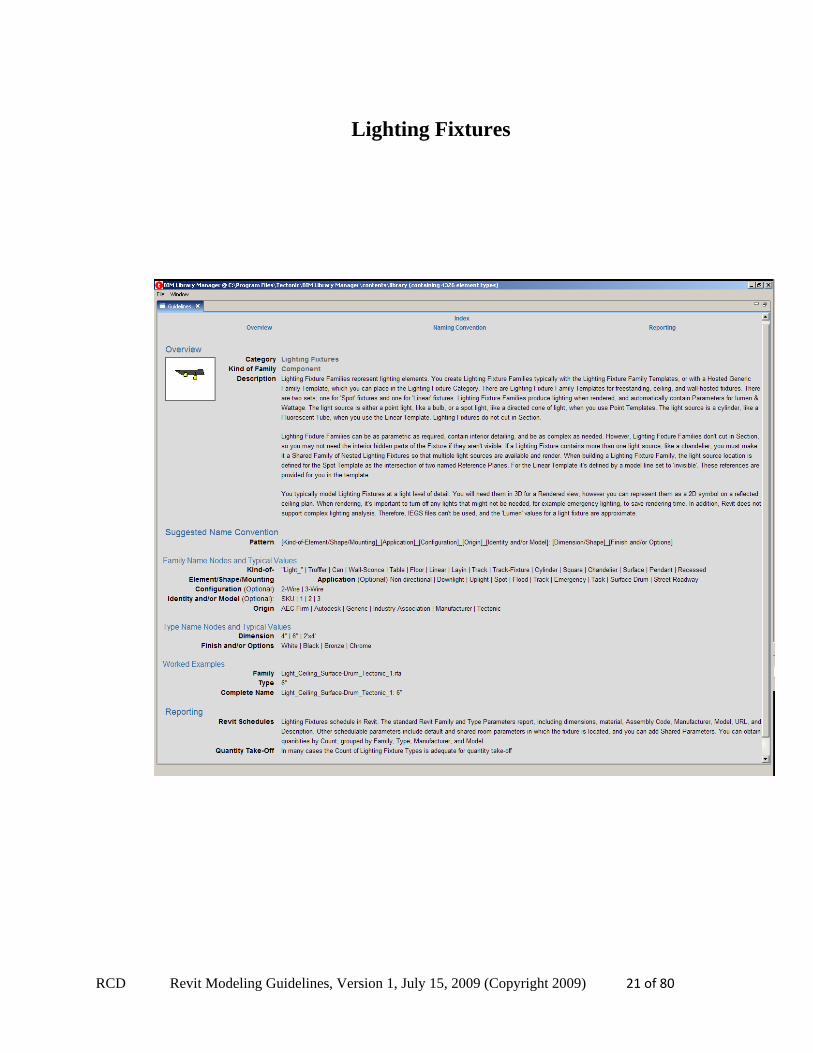
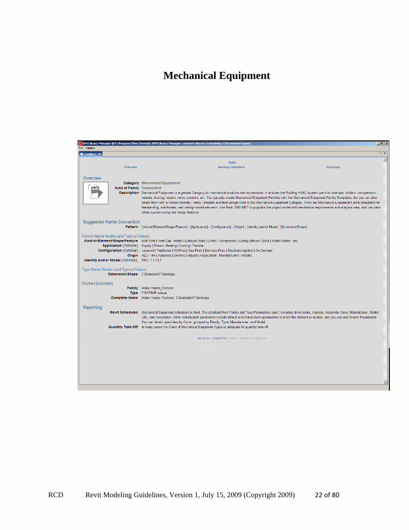
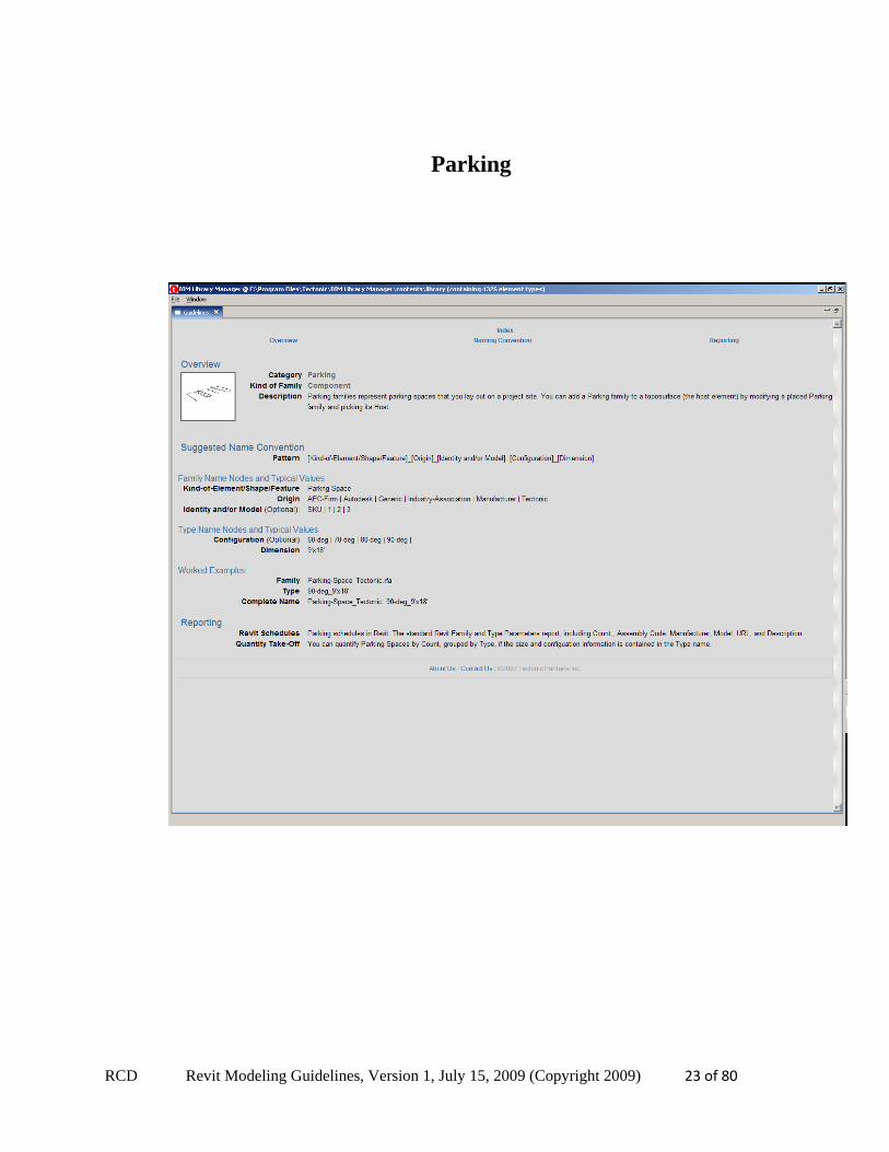
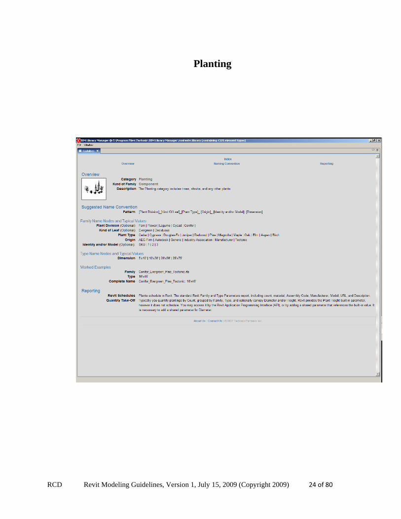
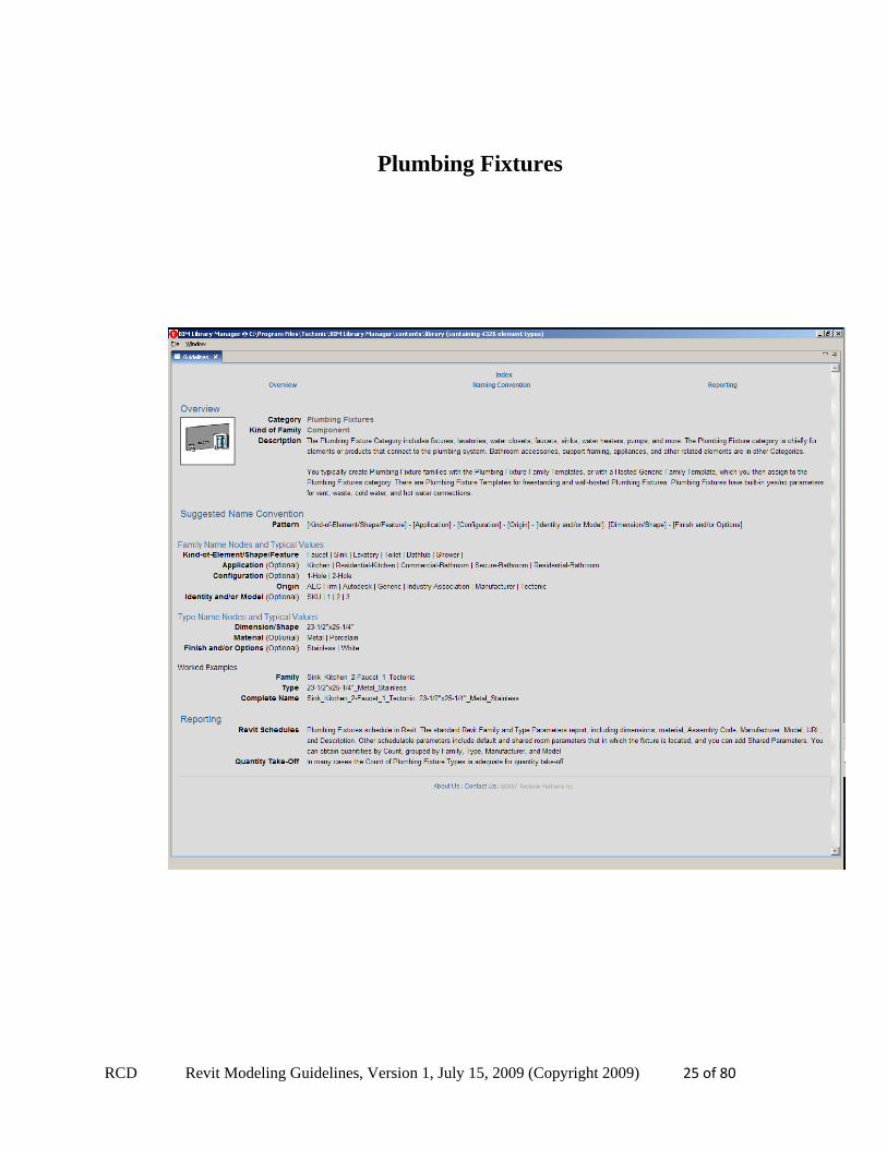
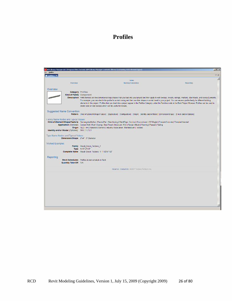
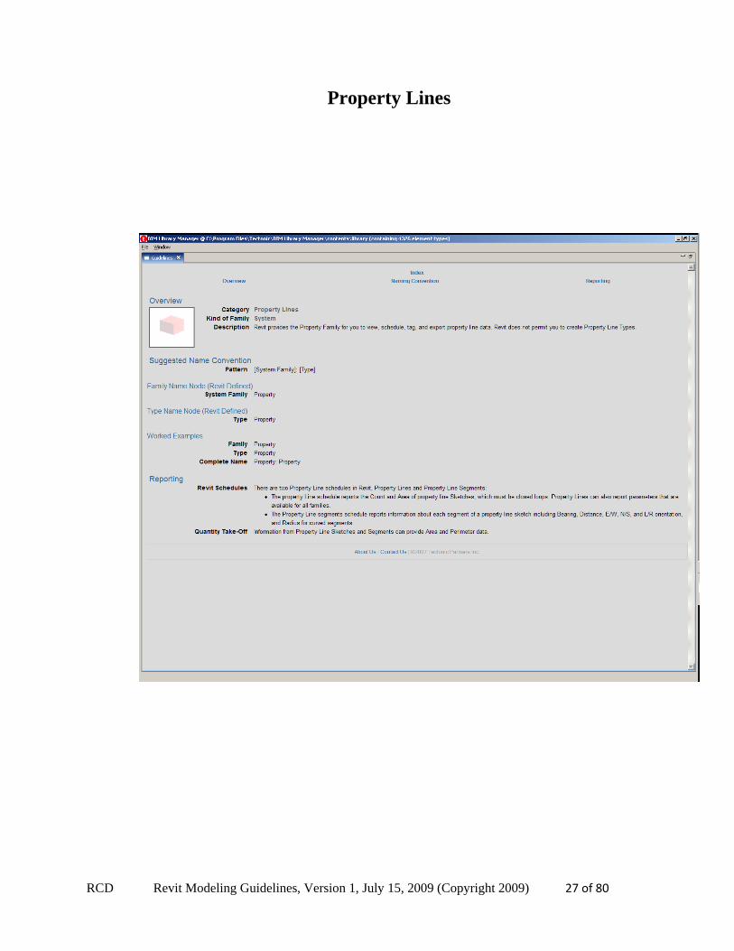
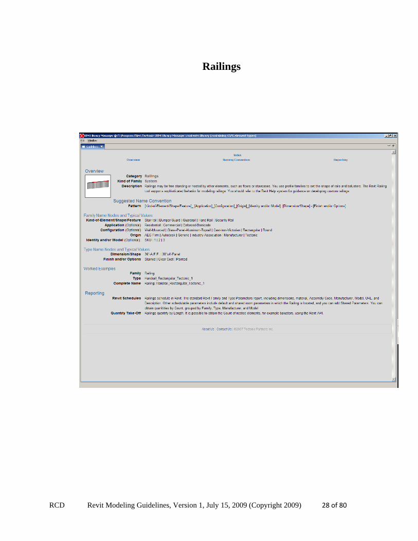
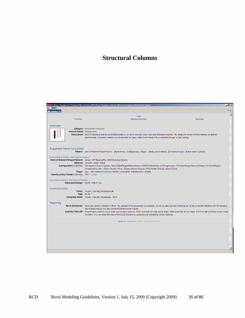
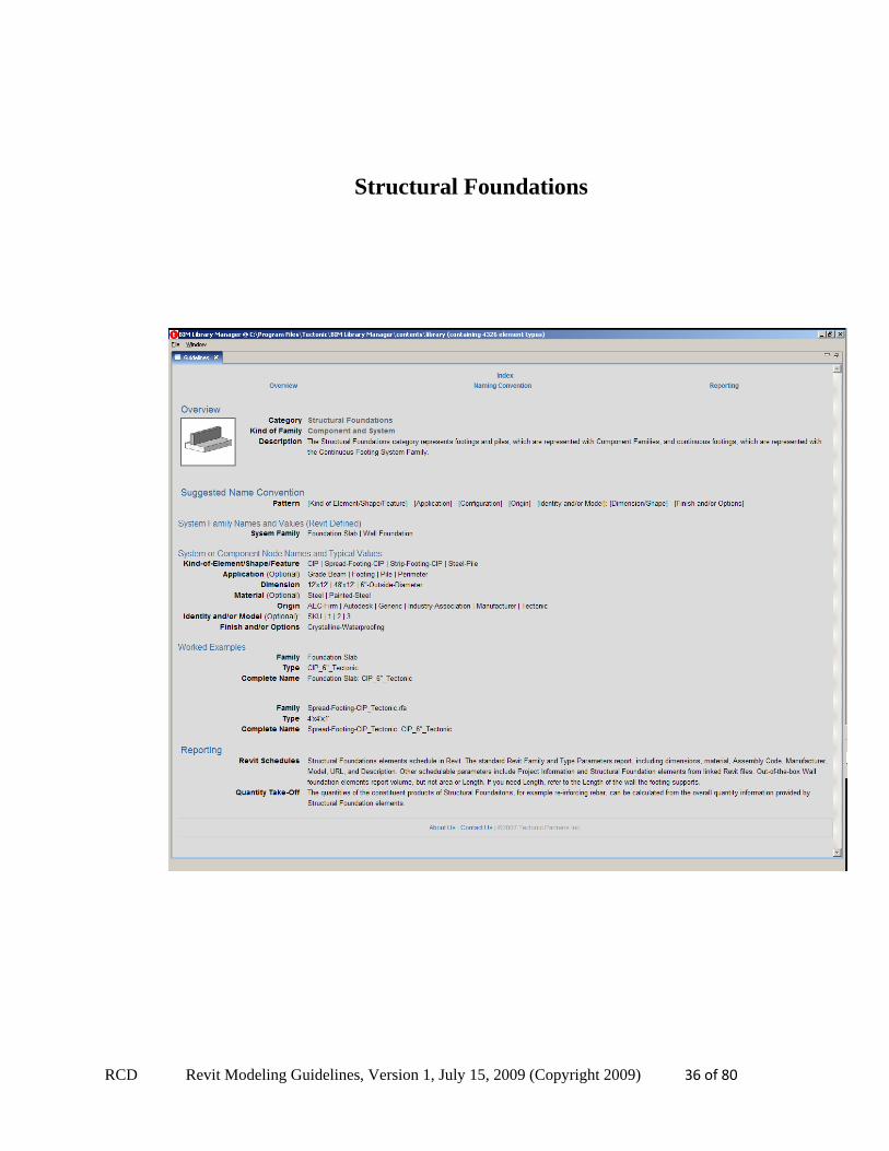
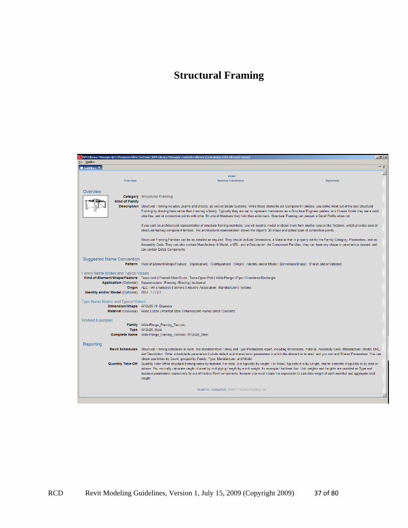
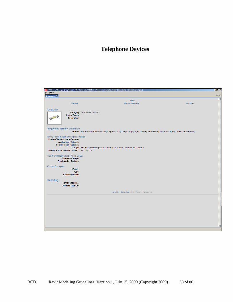
7. Naming Conventions The naming of objects and assemblies are important. There should a consistent naming convention that allows a user to navigate a large library of families easily and allows them to find what they need.
Families in a library should first of all be logically separated (Folders) by Revit modeling category. For example, Doors, Windows, etc. RCD advocates a naming convention that specifies the family from the general to the specific. This would encompass the type of object (Door), functionality, features, materials and manufacturer if necessary. Not all the fields below are required for each object. Object creation may go through several phases where each phase adds more detail to the object and a corresponding increase in the number of fields that will be filled in for the name. In some cases, such as cabinets, where there is not an industry wide convention for the order of dimensions (width, depth height) the name needs to include what dimension is referenced.
Most of the major categories have naming conventions; they are included below and can be accessed within the BIM Library Manager.
RCD Revit Modeling Guidelines, Version 1, July 15, 2009 (Copyright 2009) 6 of 80
Casework
RCD Revit Modeling Guidelines, Version 1, July 15, 2009 (Copyright 2009) 7 of 80
Ceilings
RCD Revit Modeling Guidelines, Version 1, July 15, 2009 (Copyright 2009) 8 of 80
Columns
RCD Revit Modeling Guidelines, Version 1, July 15, 2009 (Copyright 2009) 9 of 80
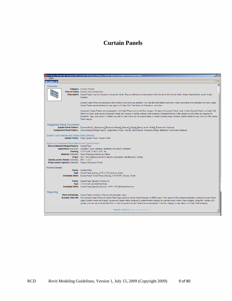
Curtain Panels
RCD Revit Modeling Guidelines, Version 1, July 15, 2009 (Copyright 2009) 10 of 80
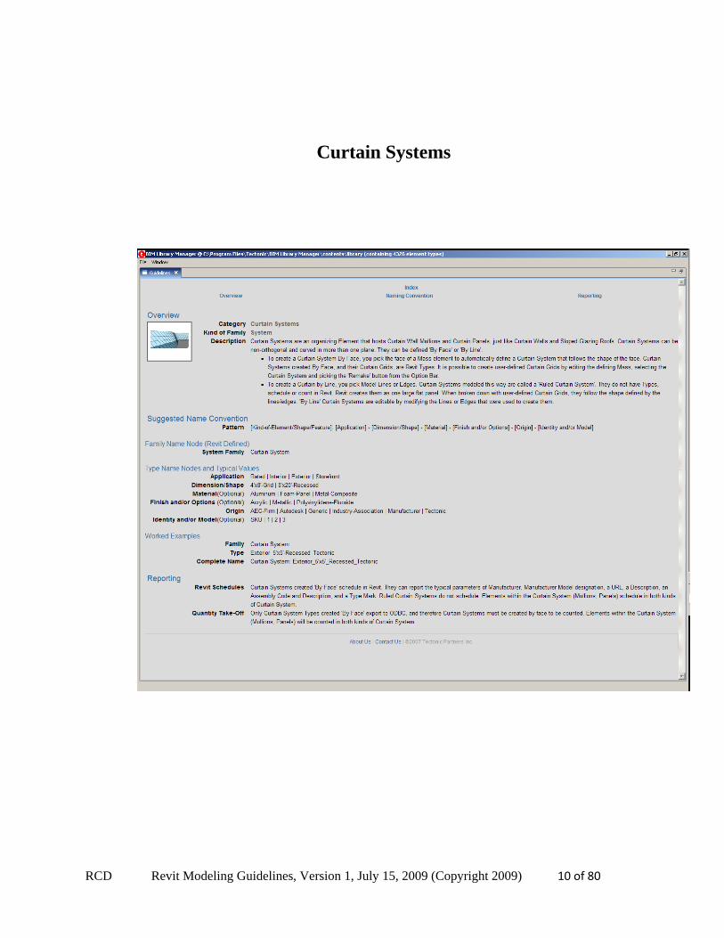
Curtain Systems
RCD Revit Modeling Guidelines, Version 1, July 15, 2009 (Copyright 2009) 11 of 80
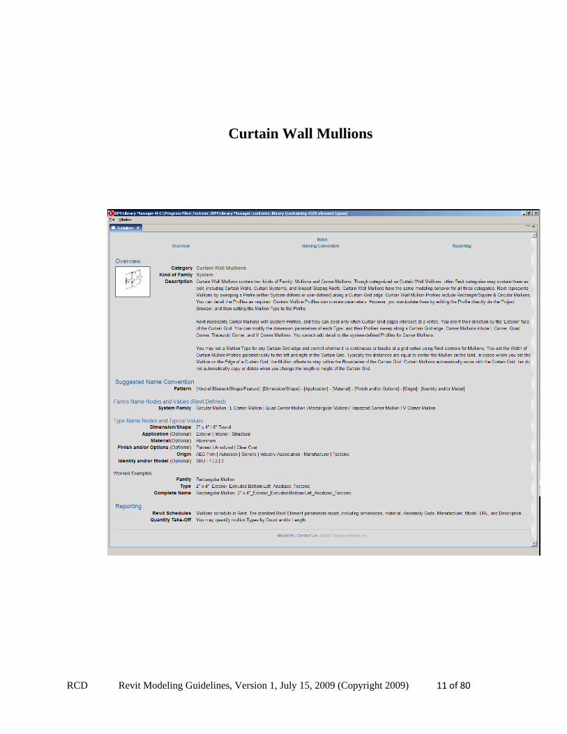
Curtain Wall Mullions
RCD Revit Modeling Guidelines, Version 1, July 15, 2009 (Copyright 2009) 12 of 80
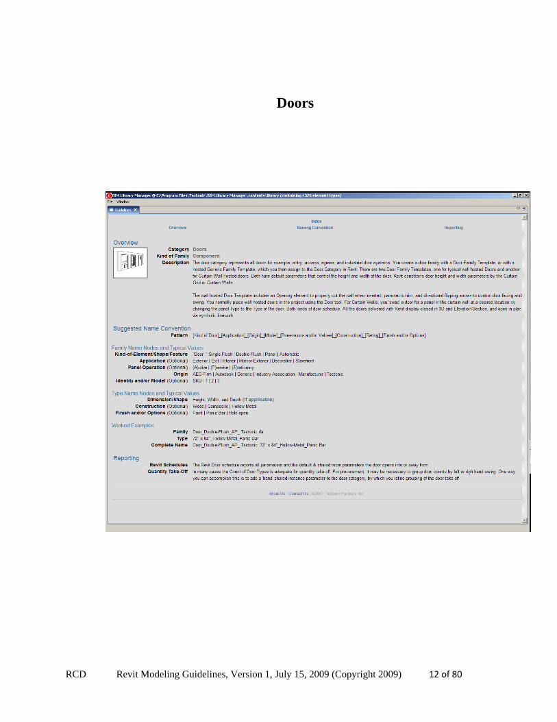
Doors
RCD Revit Modeling Guidelines, Version 1, July 15, 2009 (Copyright 2009) 13 of 80
Electrical Equipment
RCD Revit Modeling Guidelines, Version 1, July 15, 2009 (Copyright 2009) 14 of 80
Electrical Fixtures
RCD Revit Modeling Guidelines, Version 1, July 15, 2009 (Copyright 2009) 15 of 80
Fascias
RCD Revit Modeling Guidelines, Version 1, July 15, 2009 (Copyright 2009) 16 of 80
Floors
RCD Revit Modeling Guidelines, Version 1, July 15, 2009 (Copyright 2009) 17 of 80
Furniture
RCD Revit Modeling Guidelines, Version 1, July 15, 2009 (Copyright 2009) 18 of 80
Furniture Systems
RCD Revit Modeling Guidelines, Version 1, July 15, 2009 (Copyright 2009) 19 of 80
Generic Models
RCD Revit Modeling Guidelines, Version 1, July 15, 2009 (Copyright 2009) 20 of 80
Gutters
RCD Revit Modeling Guidelines, Version 1, July 15, 2009 (Copyright 2009) 21 of 80
Lighting Fixtures
RCD Revit Modeling Guidelines, Version 1, July 15, 2009 (Copyright 2009) 22 of 80
Mechanical Equipment
RCD Revit Modeling Guidelines, Version 1, July 15, 2009 (Copyright 2009) 23 of 80
Parking
RCD Revit Modeling Guidelines, Version 1, July 15, 2009 (Copyright 2009) 24 of 80
Planting
RCD Revit Modeling Guidelines, Version 1, July 15, 2009 (Copyright 2009) 25 of 80
Plumbing Fixtures
RCD Revit Modeling Guidelines, Version 1, July 15, 2009 (Copyright 2009) 26 of 80
Profiles
RCD Revit Modeling Guidelines, Version 1, July 15, 2009 (Copyright 2009) 27 of 80
Property Lines
RCD Revit Modeling Guidelines, Version 1, July 15, 2009 (Copyright 2009) 28 of 80
Railings
RCD Revit Modeling Guidelines, Version 1, July 15, 2009 (Copyright 2009) 29 of 80
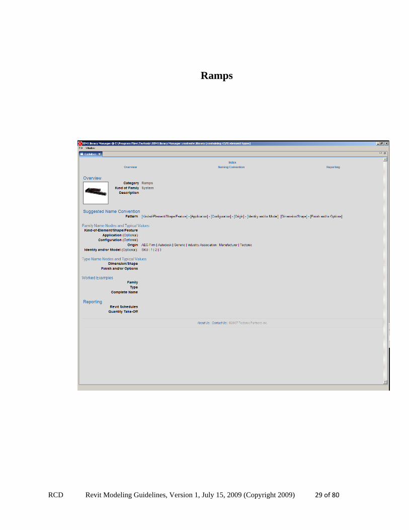
Ramps
RCD Revit Modeling Guidelines, Version 1, July 15, 2009 (Copyright 2009) 30 of 80
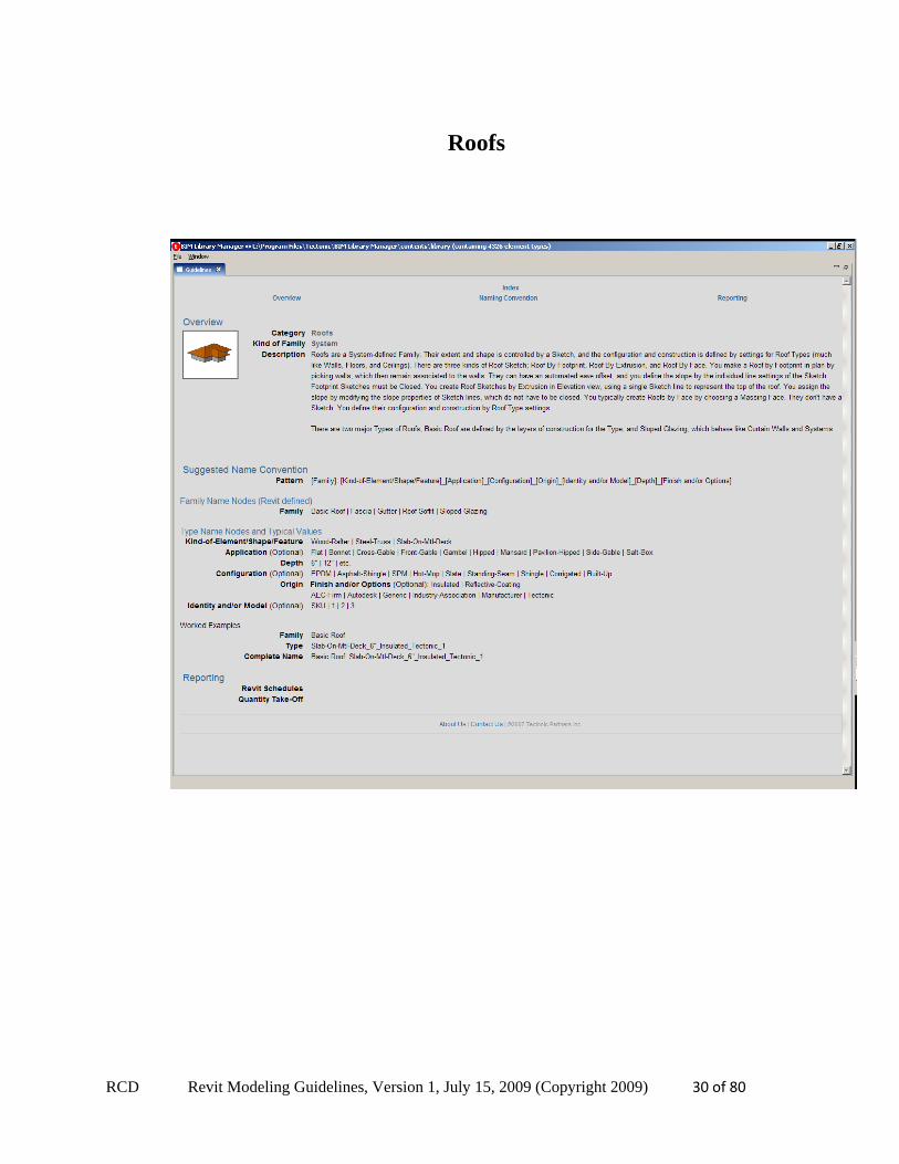
Roofs

RCD Revit Modeling Guidelines, Version 1, July 15, 2009 (Copyright 2009) 31 of 80
Site
RCD Revit Modeling Guidelines, Version 1, July 15, 2009 (Copyright 2009) 32 of 80
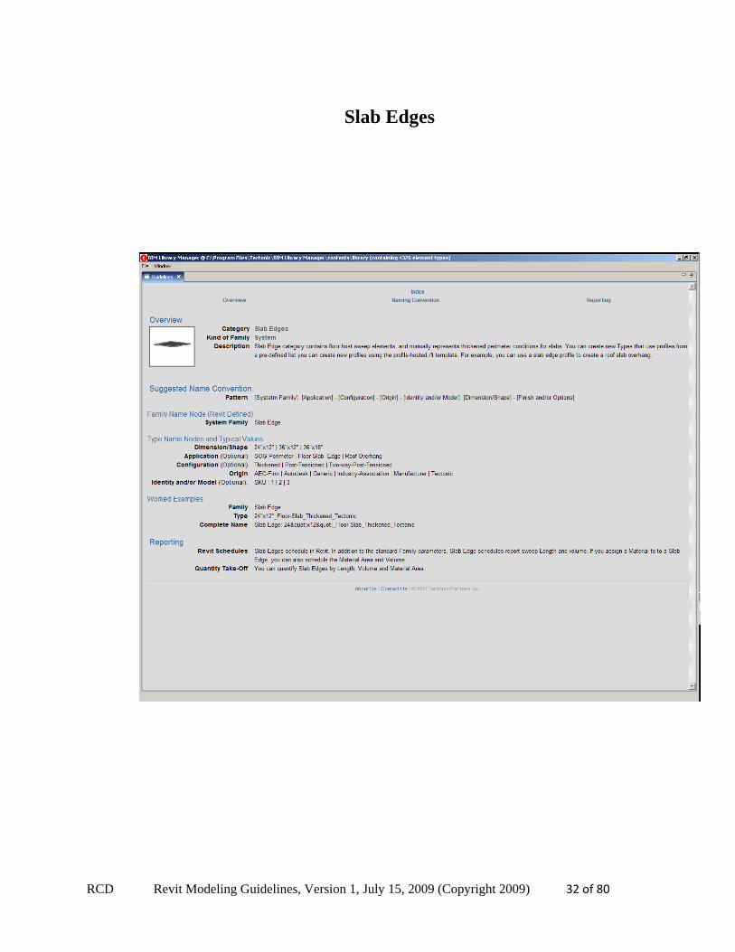
Slab Edges
RCD Revit Modeling Guidelines, Version 1, July 15, 2009 (Copyright 2009) 33 of 80
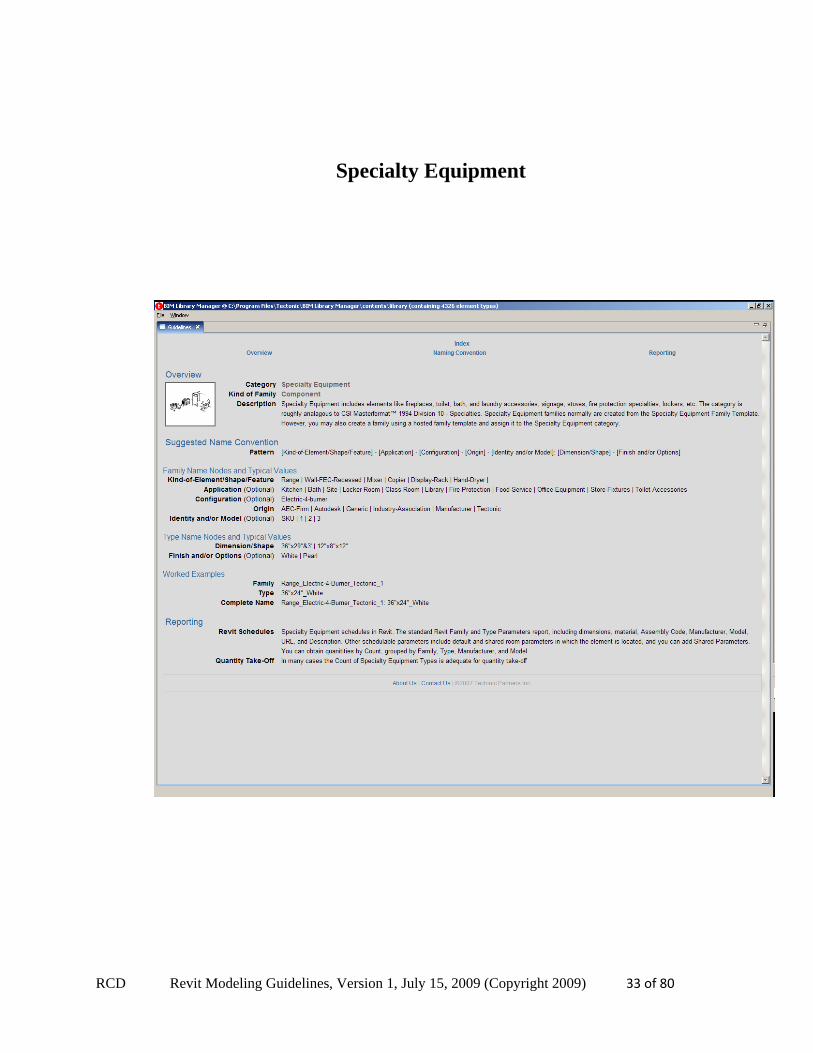
Specialty Equipment

RCD Revit Modeling Guidelines, Version 1, July 15, 2009 (Copyright 2009) 34 of 80
Stairs
RCD Revit Modeling Guidelines, Version 1, July 15, 2009 (Copyright 2009) 35 of 80
Structural Columns
RCD Revit Modeling Guidelines, Version 1, July 15, 2009 (Copyright 2009) 36 of 80
Structural Foundations
RCD Revit Modeling Guidelines, Version 1, July 15, 2009 (Copyright 2009) 37 of 80
Structural Framing
RCD Revit Modeling Guidelines, Version 1, July 15, 2009 (Copyright 2009) 38 of 80
Telephone Devices
RCD Revit Modeling Guidelines, Version 1, July 15, 2009 (Copyright 2009) 39 of 80
Topography
RCD Revit Modeling Guidelines, Version 1, July 15, 2009 (Copyright 2009) 40 of 80
Wall Sweeps
RCD Revit Modeling Guidelines, Version 1, July 15, 2009 (Copyright 2009) 41 of 80
Walls
RCD Revit Modeling Guidelines, Version 1, July 15, 2009 (Copyright 2009) 42 of 80
Windows
RCD Revit Modeling Guidelines, Version 1, July 15, 2009 (Copyright 2009) 43 of 80
8. Tutorials
To get acquainted with modeling in Revit there is an exhaustive Help File that comes with a standard Revit Installation. Typing “F1” will automatically take you to Help at anytime within the Revit application. Here you can search for assistance on a particular topic. If you have a particular window open, clicking on F1 will open up a context oriented Help. (For example, having the Family Types dialog open and hitting F1 will open the Help section on Family Types).
To learn the basics of modeling a building, there is a document called “Getting Started” which provides a comprehensive tutorial on developing a Revit model, terrain, documentation, solar studies and so on. You can access this tutorial from the Revit Application by going to Help->Getting Started. You can also access it here: http://revit.downloads.autodesk.com/download/9_1/BuildingGSGENU.pdf
Learning how to develop Revit Families and developing familiarity with the Family Editor is best done by working through some basic tutorials also within Revit. We recommend you work entirely through both of these below to get some familiarity with developing a simple parametric model.
First go to Help->Tutorials and then type the following to access the specific tutorial. The most thorough introduction to Families in Revit is the “Creating Components in the Family Editor” tutorial. However, to get a preliminary idea of the basics you can work through the following subsets:
Doors: “Door Family” – Select the tutorial called “Creating a Door Family”
Windows: “Window Family” – Select the tutorial called “Creating a Window Family”
9. Step By Step Example This section of the document is devoted to an example of the process, studies and decisions that were made in the creation of a sophisticated parametric window model for a specific customer, Kolbe.
RCD Revit Modeling Guidelines, Version 1, July 15, 2009 (Copyright 2009) 44 of 80
Gather Requirements and Data
Prior to developing a detailed family, the modeler should take time to understand the requirements of the model as defined by a manufacturer or otherwise. A BPM typically has a large array of variables in their products, but you have to focus on what is required. Below you’ll see an image of some of the options a typical manufacturer can have for a standard window.
This is a vital step as it determines what is the focus of the modeling and what is included and not included will not only be a critical factor in what gets worked on, but also limits the amount of rework in a model which can sometimes be very significant.
Some considerations when doing a BPM specific window are the following:
Are there mullions? Should the mullions be parametric (requires much more weight to the model as they have to be arrayed but is very flexible)?
Is there more than one pane of glass? If so, Is the location of the mullions variable (front side of window, between, rear side of window, or any combination)?
Are the mullions in different profiles, colors, textures?
Trim considerations – interior, exterior trims? Are the trims in a standard size or does this have to be parametric (requires a nested family).
Are there limits on sizes?
RCD Revit Modeling Guidelines, Version 1, July 15, 2009 (Copyright 2009) 45 of 80
Gather data ahead of time. When you are working on your model, arrange to have all the data available ahead of time so that there is less back-and-forth and you do not repeatedly revisit your model (this will become a problem if for example you are doing 20 windows). Here are some examples of data aspects that should be considered prior to modeling:
Vital Information:
o Naming Convention: <Casework_1-Door_RCD> o Type Name(s): <Format, if not specific>. How many types? What are all the variations? o Category: <Casework> o Default Elevation: <important for wall based families> o What are all necessary parameters: <Width, Height, Depth, etc.>
Should these be schedulable in a Revit Project (need to be Shared Parameters)
What sizes are necessary (H: 6’8”, etc.)? What range of sizes (if you Type Catalogs are needed).
Identity Data: o CSI Numbers, Model Numbers. Model Descriptions. o URL/images to model: <send JPGs, etc. with assignment>
Other Considerations o Type Catalog wanted?: Y/N o Which parameters wanted in Type Catalog? <visibility parameters, materials, etc.>
This is by no means is a complete list, just an example of some considerations that need to be done prior to modeling to make effective use of time and limit rework. Also keep in mind that depending on the type of product you will be modeling there will be different factors you will have to consider.
Modeling
Pick the correct template to start working with; it will save you time in setting up your model. Since we are building a Window, we start with the standard Revit Window template. However, it’s conceivable and even preferable that if there is a lot of common information between all of your windows (for example a specific BPM always has a set of parameters for their windows) then you should customize a template for the purpose.
From conversations with the client, it was determined that we needed to build an Awning Window family with the following requirements:
Need a flexible grill (mullion assembly) so that the user could specify the number of Horizontal and Vertical Lites.
There are two panes of glass within the window and the grilles were available in the front, in between and behind the window, or any combination.
There was an exterior trim, but no interior. Trim should be parametric. But, to be of assistance to the architect we might want to include interior trim as an option.
RCD Revit Modeling Guidelines, Version 1, July 15, 2009 (Copyright 2009) 46 of 80
Sizes: limited to simple prototype of 36 W x 36 H, but of two types. One with and one without exterior trim (so trim would have to be connected to a visibility parameter).
Grill
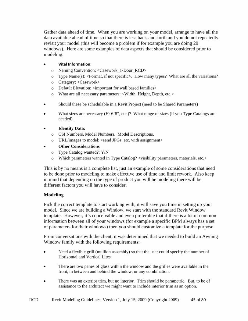
From these relatively simple set of requirements we gather that we can build two nested families. The first will be for the grill and the second for the trim. The more complicated of the two will be the grill assembly as it will incorporate arrays. This will allow the user to pick a number of grill elements and the model will dynamically generate the modifications to create that particular assembly.
TIP: Arrays are very memory-intensive constructs within Revit; they add significant size to a family and are time-consuming in generating the changes. If you do decide to use them, it’s best that arrays are built within nested families which are then introduced into your host families to maximize efficiency.
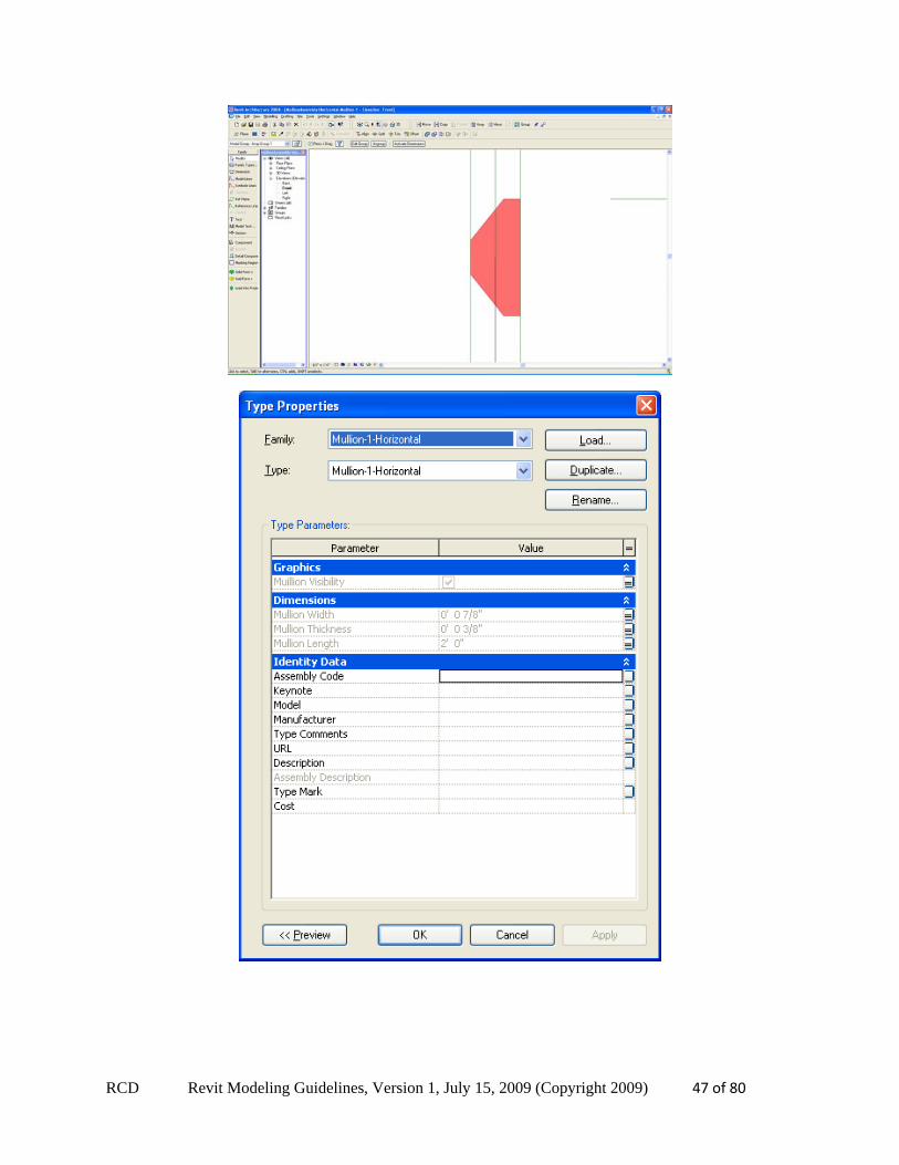
Our Grill Assembly is actually composed of two nested subcomponents – a Vertical Grill Assembly, and a Horizontal Grill Assembly. The basic element of each was an individual mullion. It was decided to model one of some variable dimensions. In incorporating this profile, the Width, Height, Thickness, Length, Mullion Visibility and Mullion Material in addition to the # of mullions were all parameters that were variable. Below are images of the profile of the mullion along with some of the parameter configurations.
RCD Revit Modeling Guidelines, Version 1, July 15, 2009 (Copyright 2009) 47 of 80
RCD Revit Modeling Guidelines, Version 1, July 15, 2009 (Copyright 2009) 48 of 80
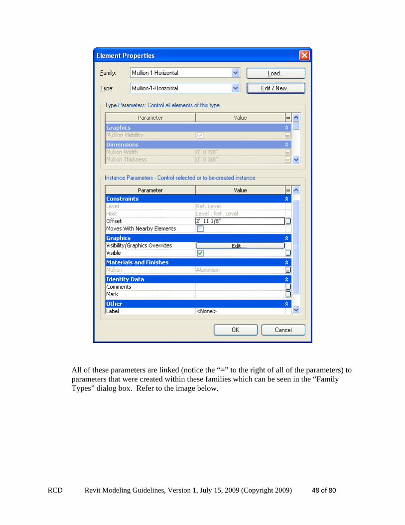
All of these parameters are linked (notice the “=” to the right of all of the parameters) to parameters that were created within these families which can be seen in the “Family Types” dialog box. Refer to the image below.
RCD Revit Modeling Guidelines, Version 1, July 15, 2009 (Copyright 2009) 49 of 80
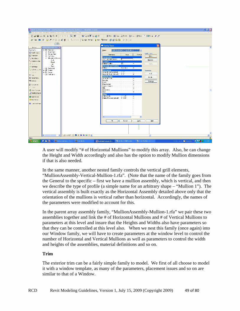
A user will modify “# of Horizontal Mullions” to modify this array. Also, he can change the Height and Width accordingly and also has the option to modify Mullion dimensions if that is also needed.
In the same manner, another nested family controls the vertical grill elements, “MullionAssembly-Vertical-Mullion-1.rfa”. (Note that the name of the family goes from the General to the specific – first we have a mullion assembly, which is vertical, and then we describe the type of profile (a simple name for an arbitrary shape – “Mullion 1”). The vertical assembly is built exactly as the Horizontal Assembly detailed above only that the orientation of the mullions is vertical rather than horizontal. Accordingly, the names of the parameters were modified to account for this.
In the parent array assembly family, “MullionAssembly-Mullion-1.rfa” we pair these two assemblies together and link the # of Horizontal Mullions and # of Vertical Mullions to parameters at this level and insure that the Heights and Widths also have parameters so that they can be controlled at this level also. When we nest this family (once again) into our Window family, we will have to create parameters at the window level to control the number of Horizontal and Vertical Mullions as well as parameters to control the width and heights of the assemblies, material definitions and so on.
Trim
The exterior trim can be a fairly simple family to model. We first of all choose to model it with a window template, as many of the parameters, placement issues and so on are similar to that of a Window.
RCD Revit Modeling Guidelines, Version 1, July 15, 2009 (Copyright 2009) 50 of 80
TIP: In addition to the previously made points regarding templates, templates also preset the Family Category for each family so in this case “Window” is already specified. This is important because this is an element that can be shown on a schedule, so it needs to be considered by the modeler in the list of requirements.
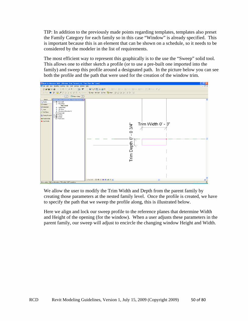
The most efficient way to represent this graphically is to the use the “Sweep” solid tool. This allows one to either sketch a profile (or to use a pre-built one imported into the family) and sweep this profile around a designated path. In the picture below you can see both the profile and the path that were used for the creation of the window trim.
We allow the user to modify the Trim Width and Depth from the parent family by creating those parameters at the nested family level. Once the profile is created, we have to specify the path that we sweep the profile along, this is illustrated below.
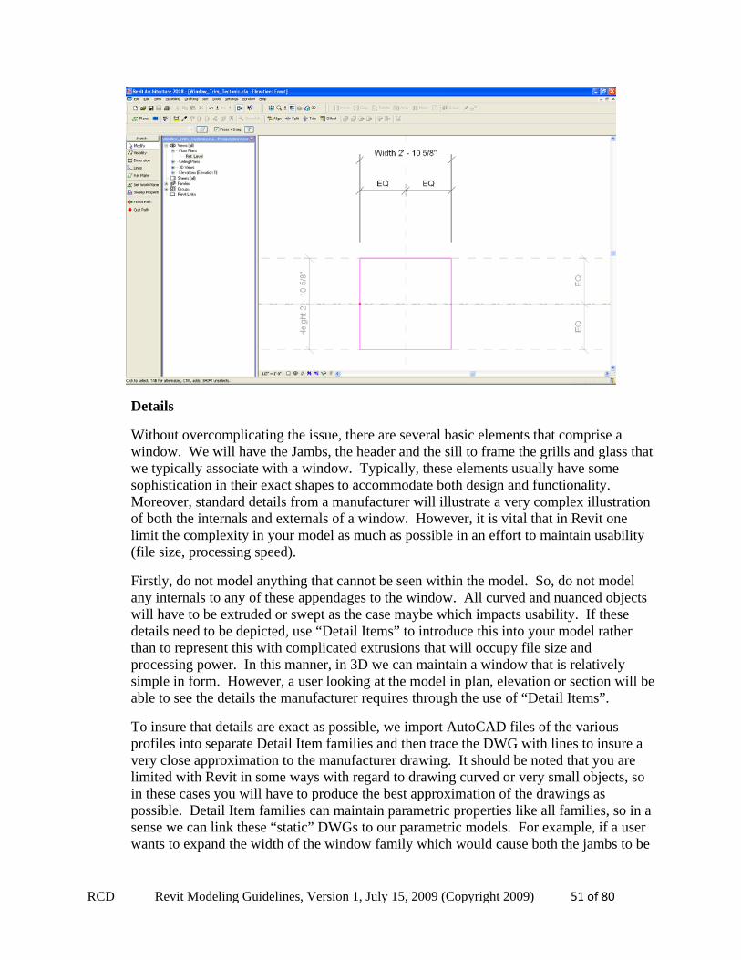
Here we align and lock our sweep profile to the reference planes that determine Width and Height of the opening (for the window). When a user adjusts these parameters in the parent family, our sweep will adjust to encircle the changing window Height and Width.
RCD Revit Modeling Guidelines, Version 1, July 15, 2009 (Copyright 2009) 51 of 80
Details
Without overcomplicating the issue, there are several basic elements that comprise a window. We will have the Jambs, the header and the sill to frame the grills and glass that we typically associate with a window. Typically, these elements usually have some sophistication in their exact shapes to accommodate both design and functionality. Moreover, standard details from a manufacturer will illustrate a very complex illustration of both the internals and externals of a window. However, it is vital that in Revit one limit the complexity in your model as much as possible in an effort to maintain usability (file size, processing speed).
Firstly, do not model anything that cannot be seen within the model. So, do not model any internals to any of these appendages to the window. All curved and nuanced objects will have to be extruded or swept as the case maybe which impacts usability. If these details need to be depicted, use “Detail Items” to introduce this into your model rather than to represent this with complicated extrusions that will occupy file size and processing power. In this manner, in 3D we can maintain a window that is relatively simple in form. However, a user looking at the model in plan, elevation or section will be able to see the details the manufacturer requires through the use of “Detail Items”.
To insure that details are exact as possible, we import AutoCAD files of the various profiles into separate Detail Item families and then trace the DWG with lines to insure a very close approximation to the manufacturer drawing. It should be noted that you are limited with Revit in some ways with regard to drawing curved or very small objects, so in these cases you will have to produce the best approximation of the drawings as possible. Detail Item families can maintain parametric properties like all families, so in a sense we can link these “static” DWGs to our parametric models. For example, if a user wants to expand the width of the window family which would cause both the jambs to be
RCD Revit Modeling Guidelines, Version 1, July 15, 2009 (Copyright 2009) 52 of 80
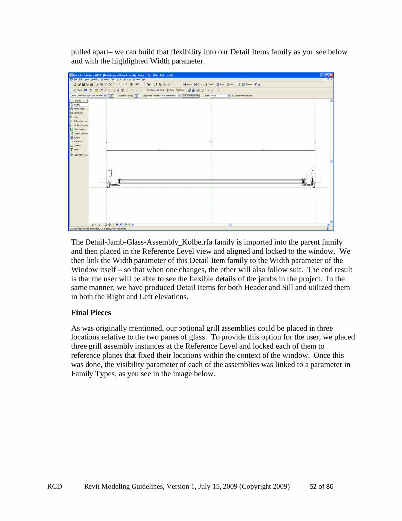
pulled apart– we can build that flexibility into our Detail Items family as you see below and with the highlighted Width parameter.
The Detail-Jamb-Glass-Assembly_Kolbe.rfa family is imported into the parent family and then placed in the Reference Level view and aligned and locked to the window. We then link the Width parameter of this Detail Item family to the Width parameter of the Window itself – so that when one changes, the other will also follow suit. The end result is that the user will be able to see the flexible details of the jambs in the project. In the same manner, we have produced Detail Items for both Header and Sill and utilized them in both the Right and Left elevations.
Final Pieces
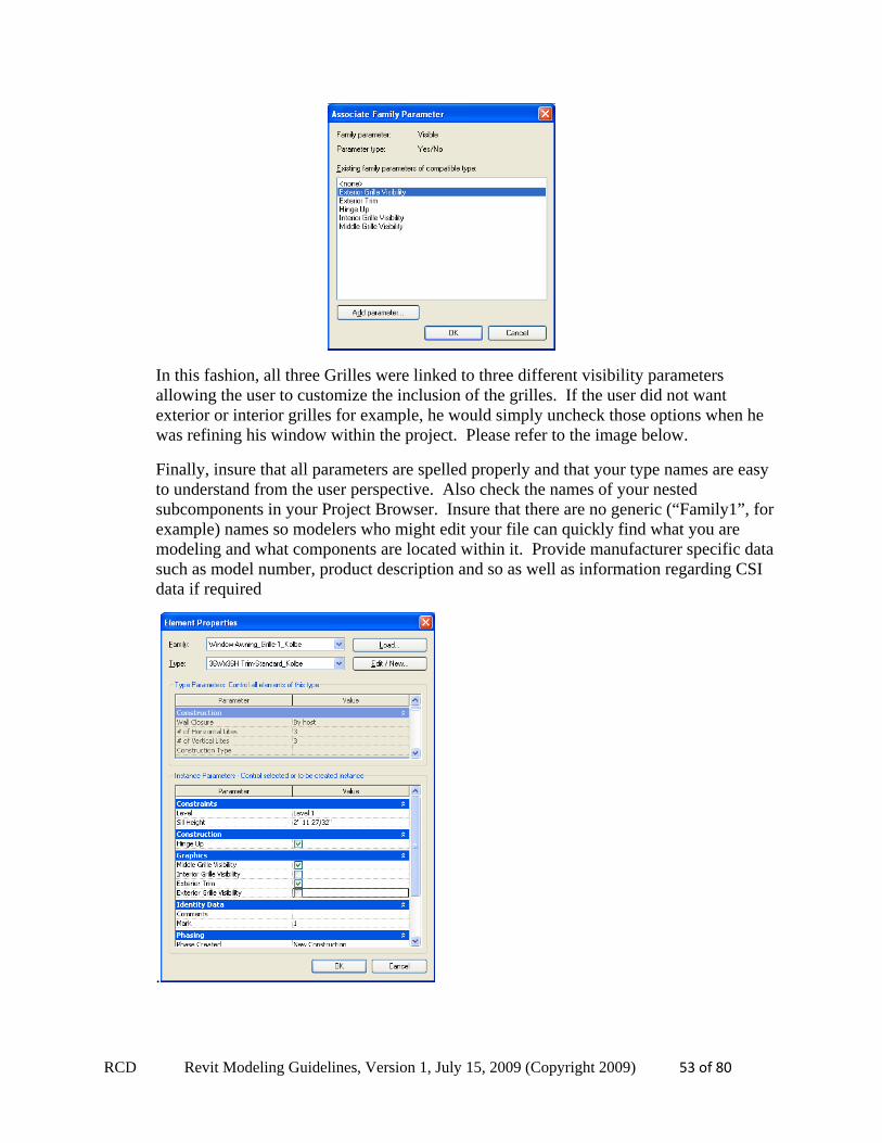
As was originally mentioned, our optional grill assemblies could be placed in three locations relative to the two panes of glass. To provide this option for the user, we placed three grill assembly instances at the Reference Level and locked each of them to reference planes that fixed their locations within the context of the window. Once this was done, the visibility parameter of each of the assemblies was linked to a parameter in Family Types, as you see in the image below.
RCD Revit Modeling Guidelines, Version 1, July 15, 2009 (Copyright 2009) 53 of 80
In this fashion, all three Grilles were linked to three different visibility parameters allowing the user to customize the inclusion of the grilles. If the user did not want exterior or interior grilles for example, he would simply uncheck those options when he was refining his window within the project. Please refer to the image below.
Finally, insure that all parameters are spelled properly and that your type names are easy to understand from the user perspective. Also check the names of your nested subcomponents in your Project Browser. Insure that there are no generic (“Family1”, for example) names so modelers who might edit your file can quickly find what you are modeling and what components are located within it. Provide manufacturer specific data such as model number, product description and so as well as information regarding CSI data if required
.
RCD Revit Modeling Guidelines, Version 1, July 15, 2009 (Copyright 2009) 54 of 80
10. Modeling Techniques This section is devoted to techniques that will help you efficiently model objects. Many of the techniques can not be discovered in the tutorials and are the result of extensive investigations or trial and error modeling studies.
Glass Visibility
Revit poses problems in revealing mullions/grills (for windows for example) if there is a solid object that is modeled in front of it, glass for instance. Regardless of the transparency quality of the glass, Revit will not show the mullions/grills.
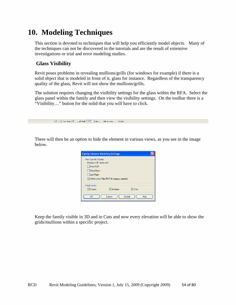
The solution requires changing the visibility settings for the glass within the RFA. Select the glass panel within the family and then view the visibility settings. On the toolbar there is a “Visibility…” button for the solid that you will have to click.
There will then be an option to hide the element in various views, as you see in the image below.
Keep the family visible in 3D and in Cuts and now every elevation will be able to show the grids/mullions within a specific project.
RCD Revit Modeling Guidelines, Version 1, July 15, 2009 (Copyright 2009) 55 of 80
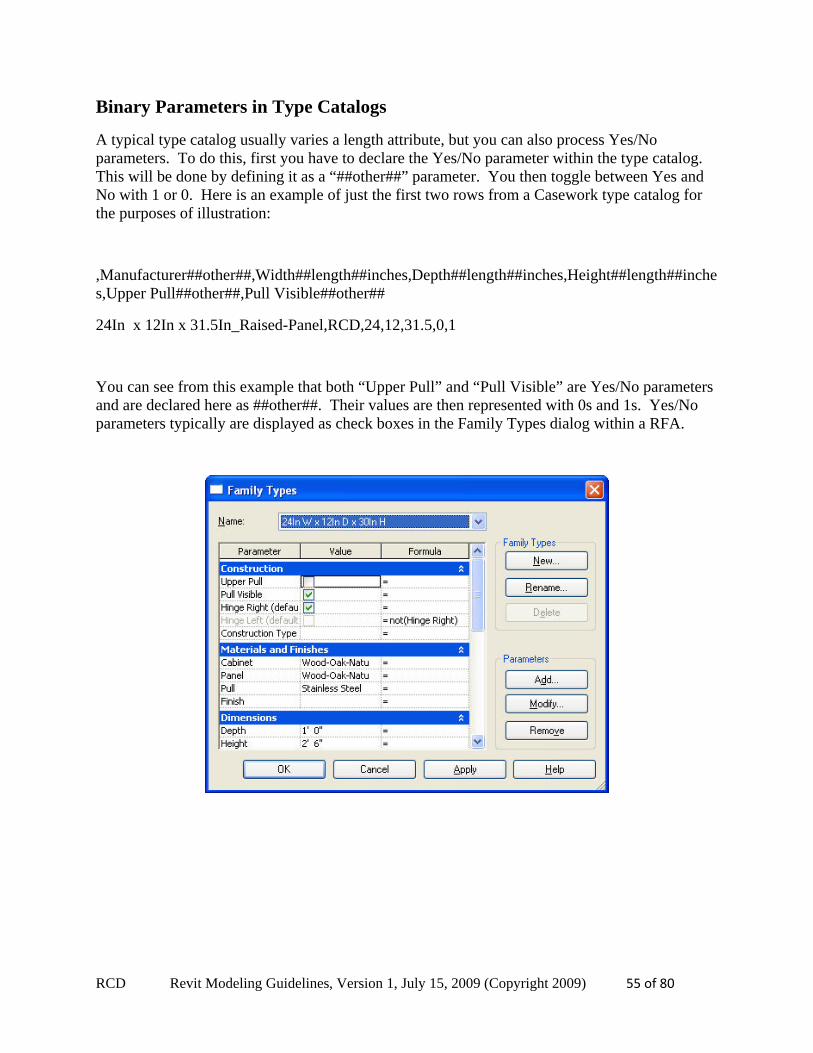
Binary Parameters in Type Catalogs
A typical type catalog usually varies a length attribute, but you can also process Yes/No parameters. To do this, first you have to declare the Yes/No parameter within the type catalog. This will be done by defining it as a “##other##” parameter. You then toggle between Yes and No with 1 or 0. Here is an example of just the first two rows from a Casework type catalog for the purposes of illustration:
,Manufacturer##other##,Width##length##inches,Depth##length##inches,Height##length##inches,Upper Pull##other##,Pull Visible##other##
24In x 12In x 31.5In_Raised-Panel,RCD,24,12,31.5,0,1
You can see from this example that both “Upper Pull” and “Pull Visible” are Yes/No parameters and are declared here as ##other##. Their values are then represented with 0s and 1s. Yes/No parameters typically are displayed as check boxes in the Family Types dialog within a RFA.
RCD Revit Modeling Guidelines, Version 1, July 15, 2009 (Copyright 2009) 56 of 80
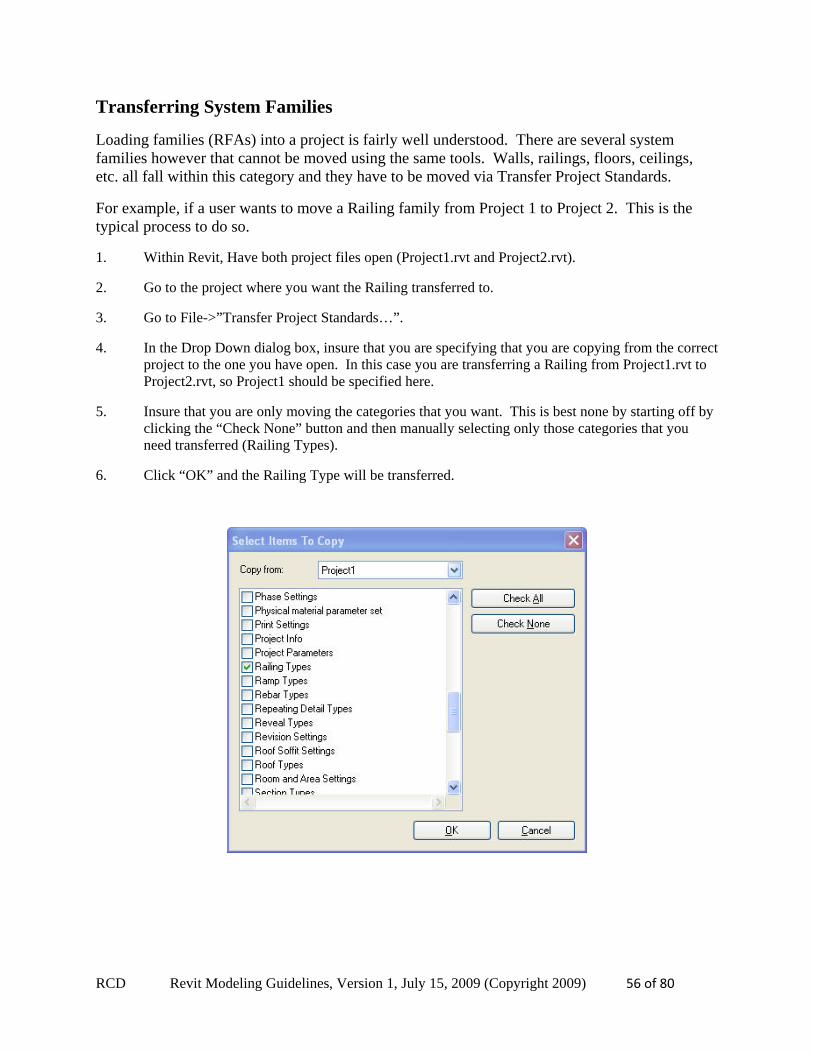
Transferring System Families
Loading families (RFAs) into a project is fairly well understood. There are several system families however that cannot be moved using the same tools. Walls, railings, floors, ceilings, etc. all fall within this category and they have to be moved via Transfer Project Standards.
For example, if a user wants to move a Railing family from Project 1 to Project 2. This is the typical process to do so.
1. Within Revit, Have both project files open (Project1.rvt and Project2.rvt).
2. Go to the project where you want the Railing transferred to.
3. Go to File->”Transfer Project Standards…”.
4. In the Drop Down dialog box, insure that you are specifying that you are copying from the correct project to the one you have open. In this case you are transferring a Railing from Project1.rvt to Project2.rvt, so Project1 should be specified here.
5. Insure that you are only moving the categories that you want. This is best none by starting off by clicking the “Check None” button and then manually selecting only those categories that you need transferred (Railing Types).
6. Click “OK” and the Railing Type will be transferred.
RCD Revit Modeling Guidelines, Version 1, July 15, 2009 (Copyright 2009) 57 of 80
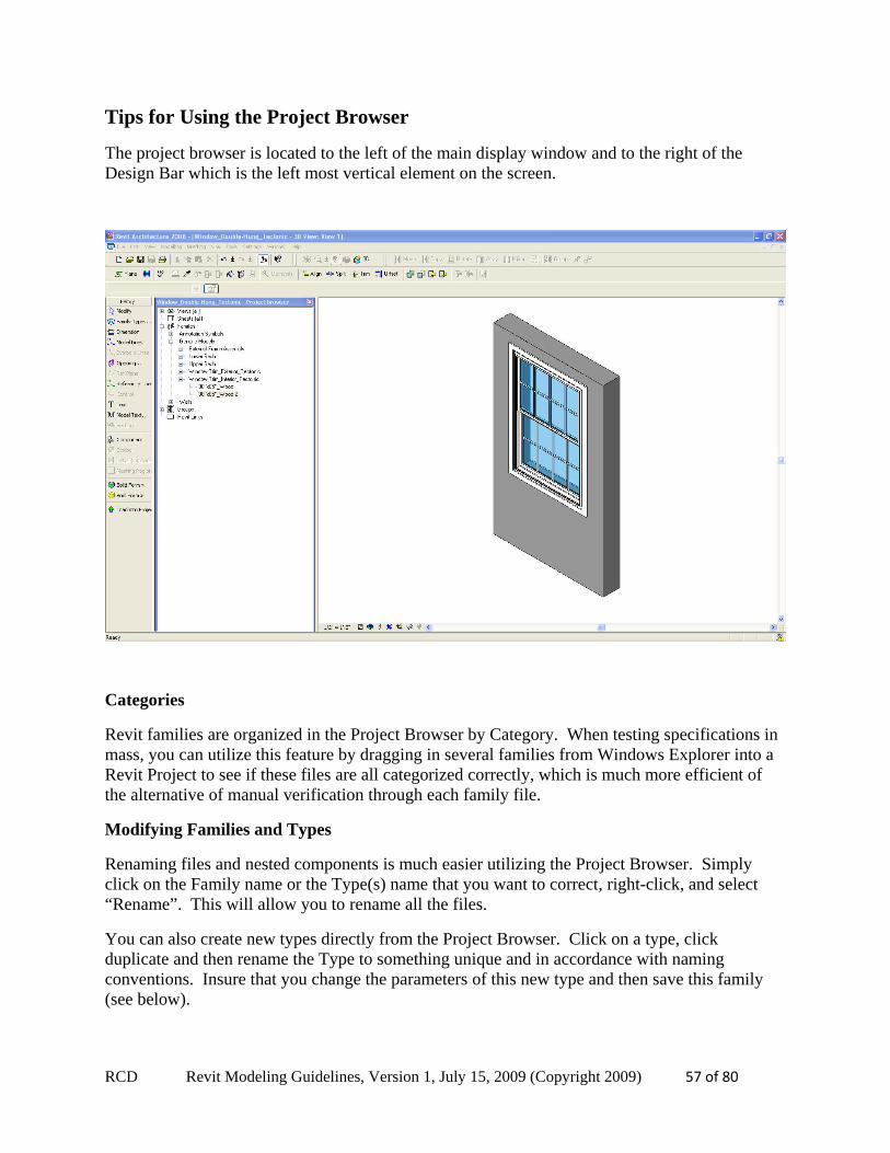
Tips for Using the Project Browser
The project browser is located to the left of the main display window and to the right of the Design Bar which is the left most vertical element on the screen.
Categories
Revit families are organized in the Project Browser by Category. When testing specifications in mass, you can utilize this feature by dragging in several families from Windows Explorer into a Revit Project to see if these files are all categorized correctly, which is much more efficient of the alternative of manual verification through each family file.
Modifying Families and Types
Renaming files and nested components is much easier utilizing the Project Browser. Simply click on the Family name or the Type(s) name that you want to correct, right-click, and select “Rename”. This will allow you to rename all the files.
You can also create new types directly from the Project Browser. Click on a type, click duplicate and then rename the Type to something unique and in accordance with naming conventions. Insure that you change the parameters of this new type and then save this family (see below).
RCD Revit Modeling Guidelines, Version 1, July 15, 2009 (Copyright 2009) 58 of 80
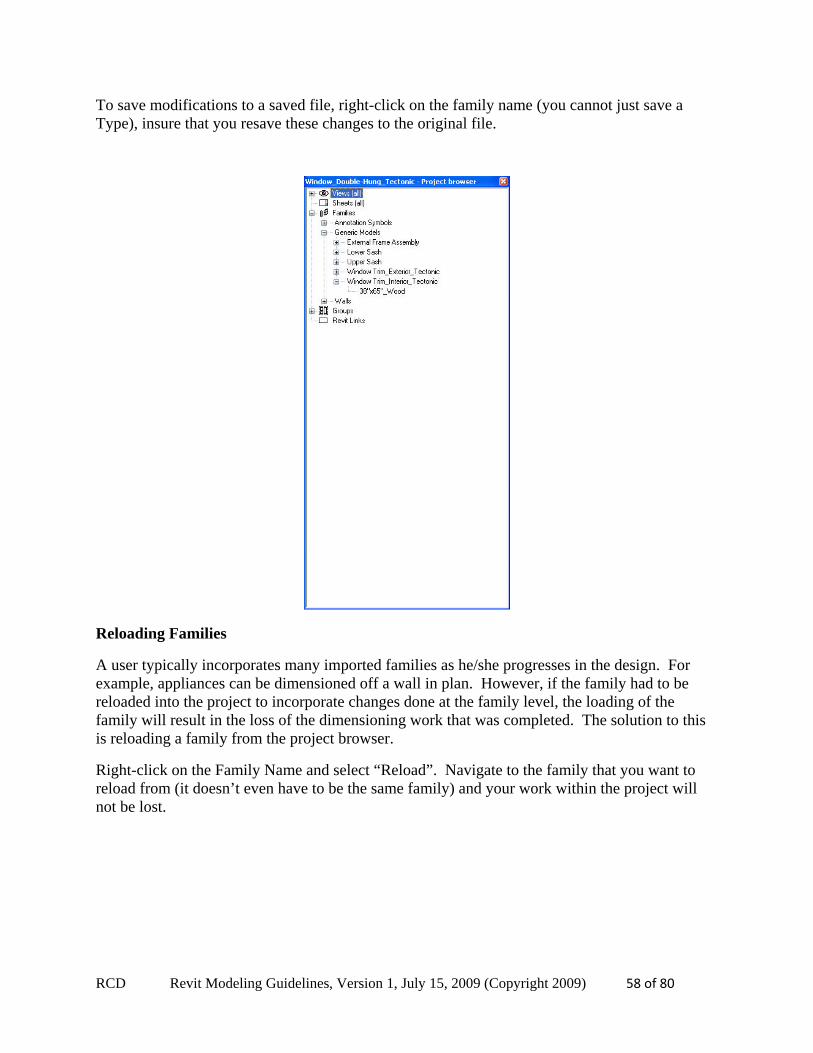
To save modifications to a saved file, right-click on the family name (you cannot just save a Type), insure that you resave these changes to the original file.
Reloading Families
A user typically incorporates many imported families as he/she progresses in the design. For example, appliances can be dimensioned off a wall in plan. However, if the family had to be reloaded into the project to incorporate changes done at the family level, the loading of the family will result in the loss of the dimensioning work that was completed. The solution to this is reloading a family from the project browser.
Right-click on the Family Name and select “Reload”. Navigate to the family that you want to reload from (it doesn’t even have to be the same family) and your work within the project will not be lost.

RCD Revit Modeling Guidelines, Version 1, July 15, 2009 (Copyright 2009) 59 of 80
Conditional Formulas in RFAs
This is directly excerpted from the Revit Help (“Conditional Statements in Formulas”), but needs to be understood clearly by anyone using formulas regularly:
Syntax for Conditional Statements
A conditional statement uses this structure: IF (<condition>, <result-if-true>, <result-if-false>)
This means that the values entered for the parameter depend on whether the condition is satisfied (true) or not satisfied (false). If the condition is true, the software returns the true value. If the condition is false, it returns the false value.
Conditional statements can contain numeric values, numeric parameter names, and Yes/No parameters. You can use the following comparisons in a condition: <, >, =. You can also use Boolean operators with a conditional statement: AND, OR, NOT. Currently, <= and >= are not implemented. To express such a comparison, you can use a logical NOT. For example, a<=b can be entered as NOT(a>b).
The following are sample formulas that use conditional statements.
Simple IF: =IF (Length < 3000mm, 200mm, 300mm)
IF with a text parameter: =IF (Length > 35', “String1”, “String2”)
IF with logical AND: =IF ( AND (x = 1 , y = 2), 8 , 3 )
IF with logical OR: =IF ( OR ( A = 1 , B = 3 ) , 8 , 3 )
Embedded IF statements: =IF ( Length < 35' , 2' 6" , IF ( Length < 45' , 3' , IF ( Length < 55' , 5' , 8' ) ) )
IF with Yes/No condition: =Length > 40 (Note that both the condition and the results are implied.)
RCD Revit Modeling Guidelines, Version 1, July 15, 2009 (Copyright 2009) 60 of 80
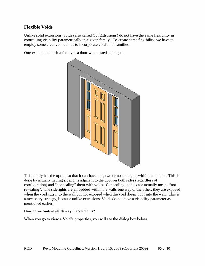
Flexible Voids
Unlike solid extrusions, voids (also called Cut Extrusions) do not have the same flexibility in controlling visibility parametrically in a given family. To create some flexibility, we have to employ some creative methods to incorporate voids into families.
One example of such a family is a door with nested sidelights.
This family has the option so that it can have one, two or no sidelights within the model. This is done by actually having sidelights adjacent to the door on both sides (regardless of configuration) and “concealing” them with voids. Concealing in this case actually means “not revealing”. The sidelights are embedded within the walls one way or the other; they are exposed when the void cuts into the wall but not exposed when the void doesn’t cut into the wall. This is a necessary strategy, because unlike extrusions, Voids do not have a visibility parameter as mentioned earlier.
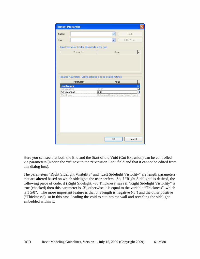
How do we control which way the Void cuts?
When you go to view a Void’s properties, you will see the dialog box below.
RCD Revit Modeling Guidelines, Version 1, July 15, 2009 (Copyright 2009) 61 of 80
Here you can see that both the End and the Start of the Void (Cut Extrusion) can be controlled via parameters (Notice the “=” next to the “Extrusion End” field and that it cannot be edited from this dialog box).
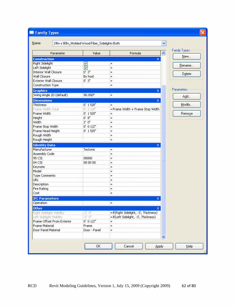
The parameters “Right Sidelight Visibility” and “Left Sidelight Visibility“ are length parameters that are altered based on which sidelights the user prefers. So if “Right Sidelight” is desired, the following piece of code, if (Right Sidelight, -3', Thickness) says if “Right Sidelight Visibility” is true (checked) then this parameter is -3’, otherwise it is equal to the variable “Thickness”, which is 1 5/8”. The more important feature is that one length is negative (-3’) and the other positive (“Thickness”), so in this case, leading the void to cut into the wall and revealing the sidelight embedded within it.
RCD Revit Modeling Guidelines, Version 1, July 15, 2009 (Copyright 2009) 62 of 80
RCD Revit Modeling Guidelines, Version 1, July 15, 2009 (Copyright 2009) 63 of 80
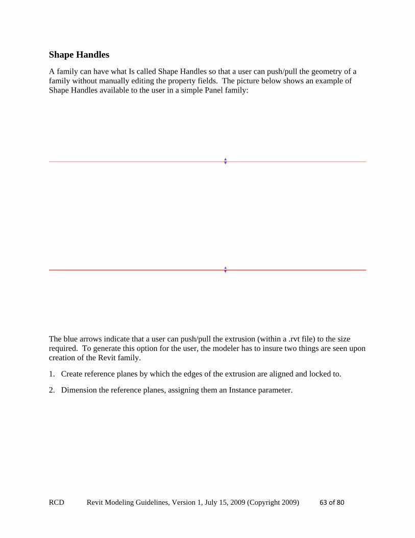
Shape Handles
A family can have what Is called Shape Handles so that a user can push/pull the geometry of a family without manually editing the property fields. The picture below shows an example of Shape Handles available to the user in a simple Panel family:
The blue arrows indicate that a user can push/pull the extrusion (within a .rvt file) to the size required. To generate this option for the user, the modeler has to insure two things are seen upon creation of the Revit family.
1. Create reference planes by which the edges of the extrusion are aligned and locked to.
2. Dimension the reference planes, assigning them an Instance parameter.
RCD Revit Modeling Guidelines, Version 1, July 15, 2009 (Copyright 2009) 64 of 80
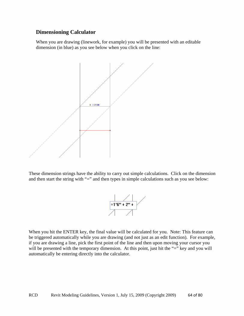
Dimensioning Calculator
When you are drawing (linework, for example) you will be presented with an editable dimension (in blue) as you see below when you click on the line:
These dimension strings have the ability to carry out simple calculations. Click on the dimension and then start the string with “=” and then types in simple calculations such as you see below:
When you hit the ENTER key, the final value will be calculated for you. Note: This feature can be triggered automatically while you are drawing (and not just as an edit function). For example, if you are drawing a line, pick the first point of the line and then upon moving your cursor you will be presented with the temporary dimension. At this point, just hit the “=” key and you will automatically be entering directly into the calculator.
RCD Revit Modeling Guidelines, Version 1, July 15, 2009 (Copyright 2009) 65 of 80
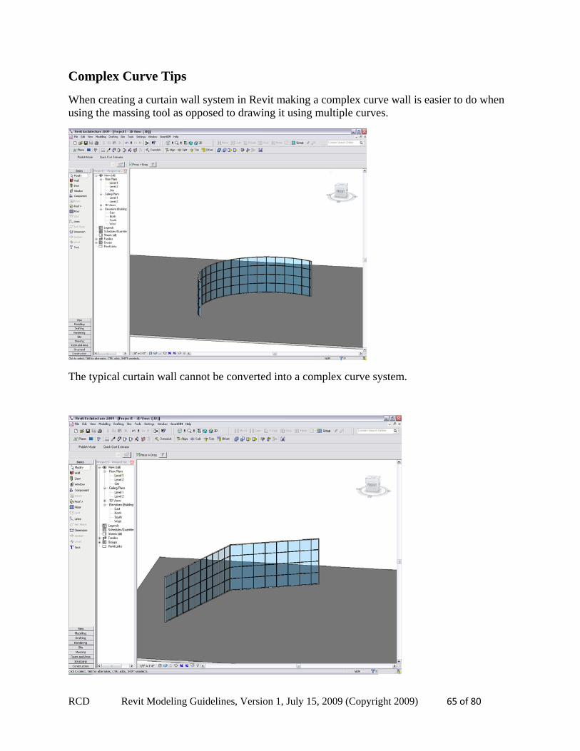
Complex Curve Tips
When creating a curtain wall system in Revit making a complex curve wall is easier to do when using the massing tool as opposed to drawing it using multiple curves.
The typical curtain wall cannot be converted into a complex curve system.
RCD Revit Modeling Guidelines, Version 1, July 15, 2009 (Copyright 2009) 66 of 80
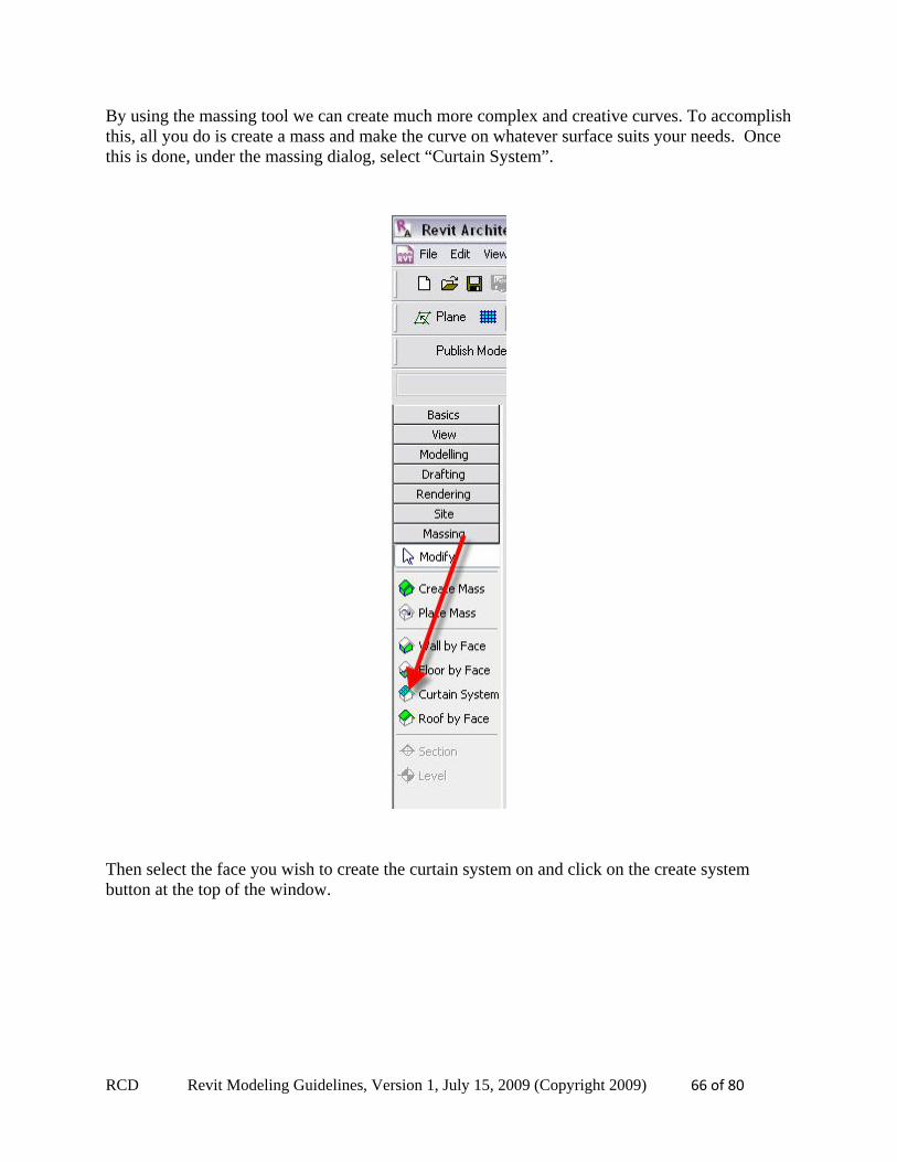
By using the massing tool we can create much more complex and creative curves. To accomplish this, all you do is create a mass and make the curve on whatever surface suits your needs. Once this is done, under the massing dialog, select “Curtain System”.
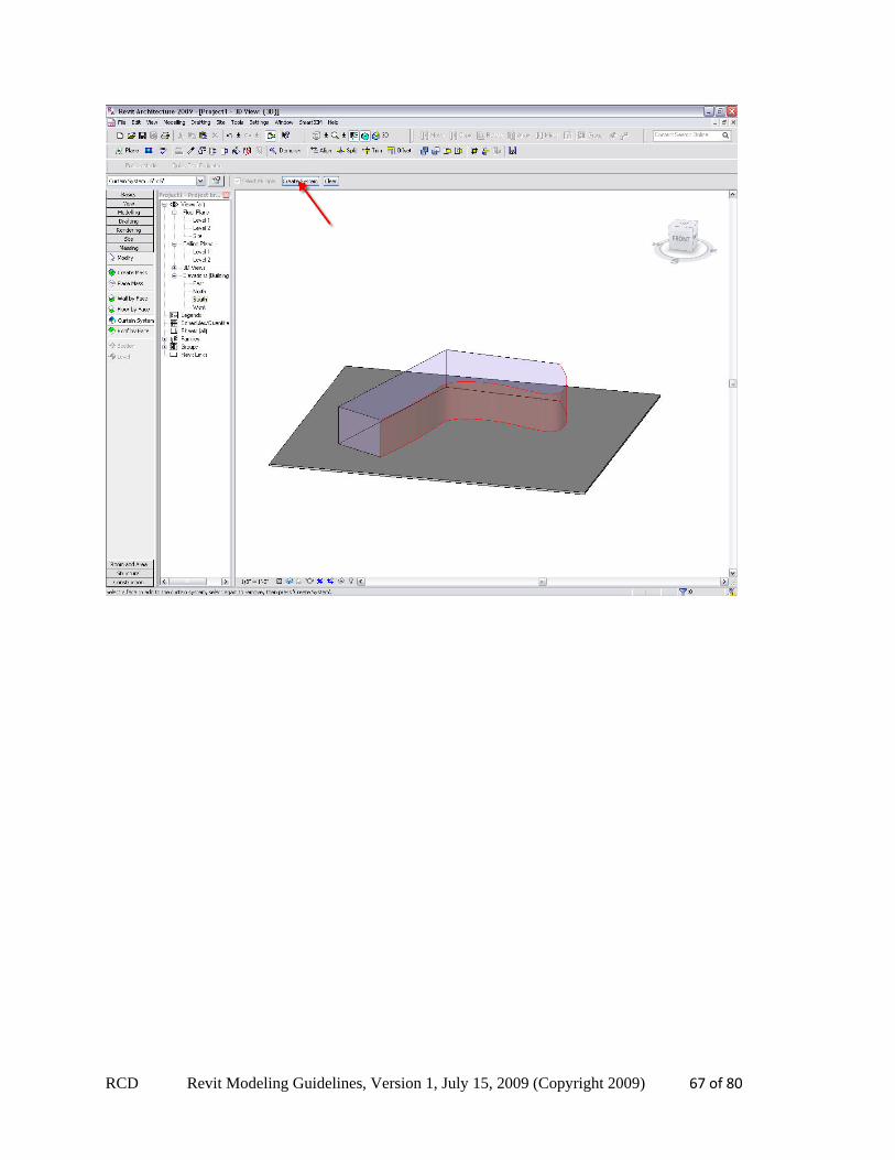
Then select the face you wish to create the curtain system on and click on the create system button at the top of the window.
RCD Revit Modeling Guidelines, Version 1, July 15, 2009 (Copyright 2009) 67 of 80
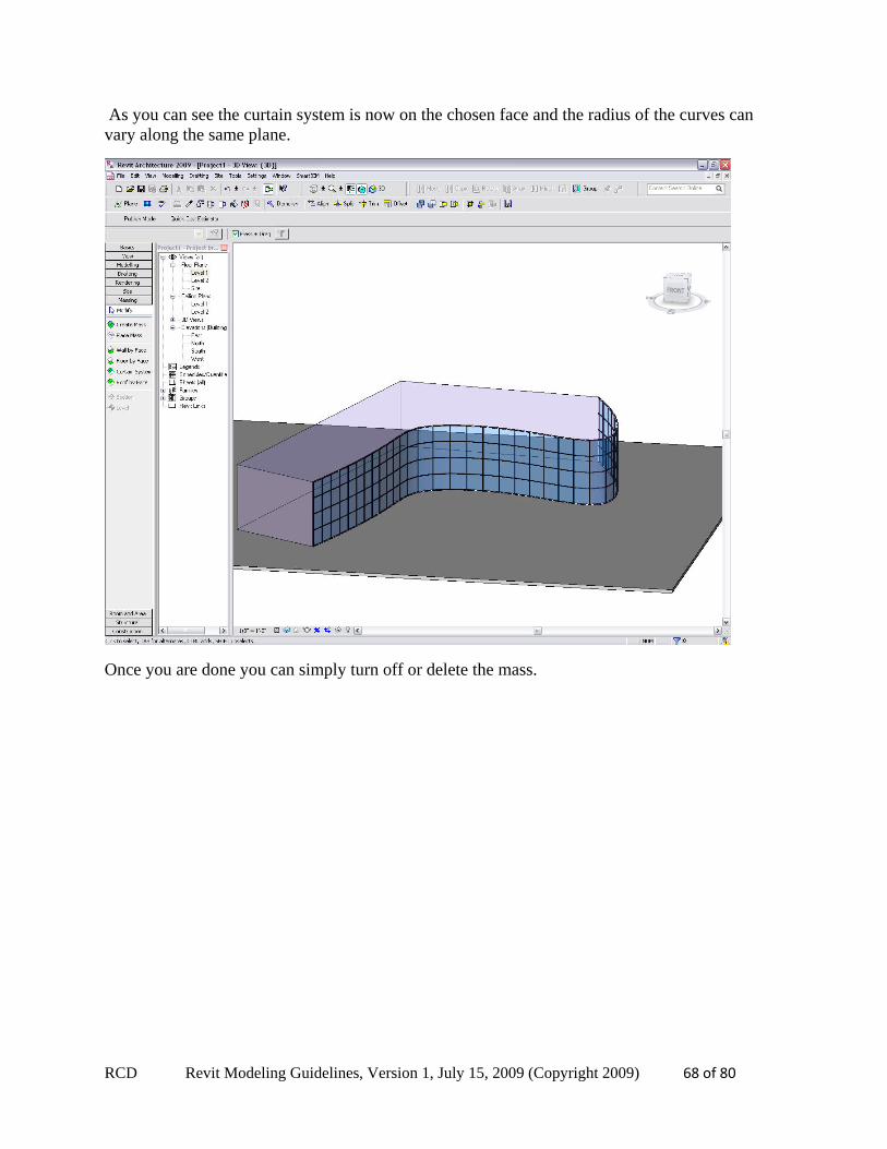
RCD Revit Modeling Guidelines, Version 1, July 15, 2009 (Copyright 2009) 68 of 80
As you can see the curtain system is now on the chosen face and the radius of the curves can vary along the same plane.
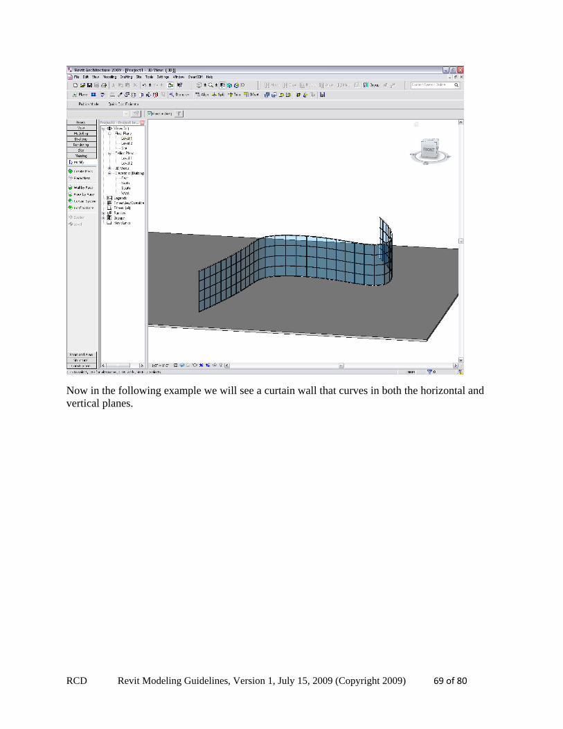
Once you are done you can simply turn off or delete the mass.
RCD Revit Modeling Guidelines, Version 1, July 15, 2009 (Copyright 2009) 69 of 80
Now in the following example we will see a curtain wall that curves in both the horizontal and vertical planes.
RCD Revit Modeling Guidelines, Version 1, July 15, 2009 (Copyright 2009) 70 of 80
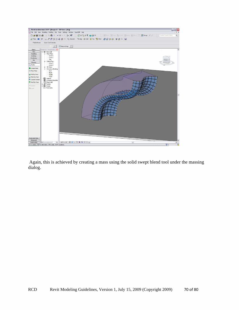
Again, this is achieved by creating a mass using the solid swept blend tool under the massing dialog.
RCD Revit Modeling Guidelines, Version 1, July 15, 2009 (Copyright 2009) 71 of 80
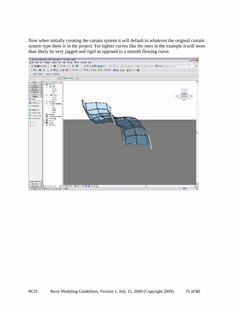
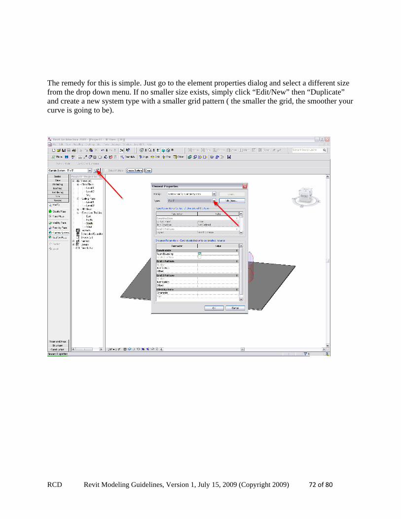
Now when initially creating the curtain system it will default to whatever the original curtain system type there is in the project. For tighter curves like the ones in the example it will more than likely be very jagged and rigid as opposed to a smooth flowing curve.
RCD Revit Modeling Guidelines, Version 1, July 15, 2009 (Copyright 2009) 72 of 80
The remedy for this is simple. Just go to the element properties dialog and select a different size from the drop down menu. If no smaller size exists, simply click “Edit/New” then “Duplicate” and create a new system type with a smaller grid pattern ( the smaller the grid, the smoother your curve is going to be).
RCD Revit Modeling Guidelines, Version 1, July 15, 2009 (Copyright 2009) 73 of 80
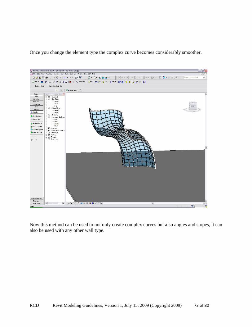
Once you change the element type the complex curve becomes considerably smoother.
Now this method can be used to not only create complex curves but also angles and slopes, it can also be used with any other wall type.
RCD Revit Modeling Guidelines, Version 1, July 15, 2009 (Copyright 2009) 74 of 80
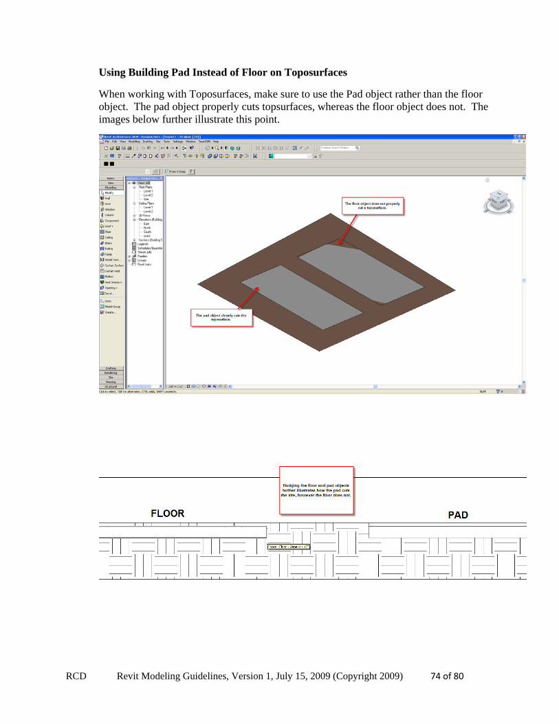
Using Building Pad Instead of Floor on Toposurfaces
When working with Toposurfaces, make sure to use the Pad object rather than the floor object. The pad object properly cuts topsurfaces, whereas the floor object does not. The images below further illustrate this point.
RCD Revit Modeling Guidelines, Version 1, July 15, 2009 (Copyright 2009) 75 of 80
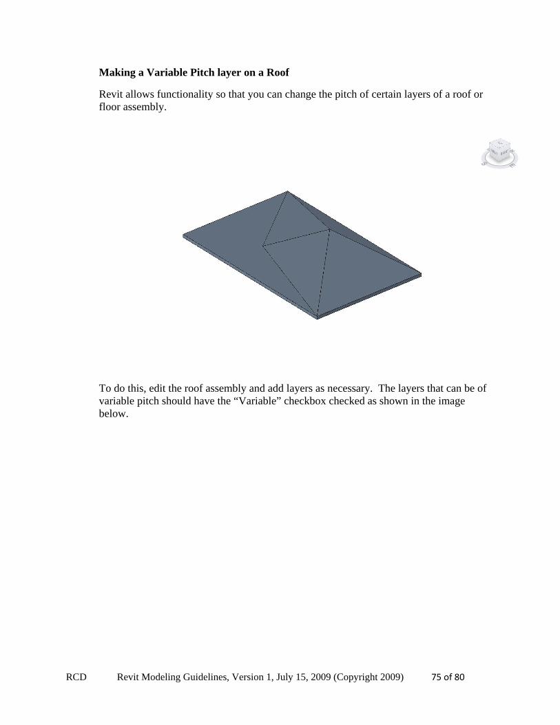
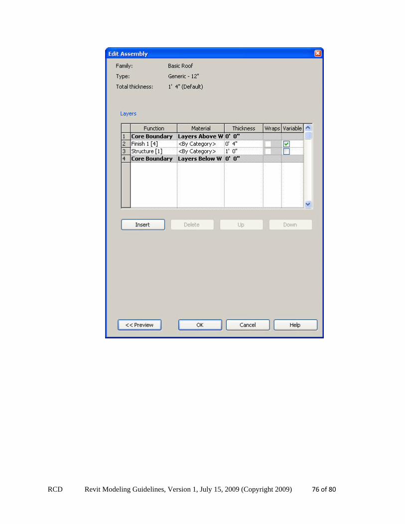
Making a Variable Pitch layer on a Roof
Revit allows functionality so that you can change the pitch of certain layers of a roof or floor assembly.
To do this, edit the roof assembly and add layers as necessary. The layers that can be of variable pitch should have the “Variable” checkbox checked as shown in the image below.
RCD Revit Modeling Guidelines, Version 1, July 15, 2009 (Copyright 2009) 76 of 80
RCD Revit Modeling Guidelines, Version 1, July 15, 2009 (Copyright 2009) 77 of 80
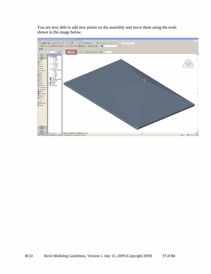
You are now able to add new points on the assembly and move them using the tools shown in the image below.
RCD Revit Modeling Guidelines, Version 1, July 15, 2009 (Copyright 2009) 78 of 80
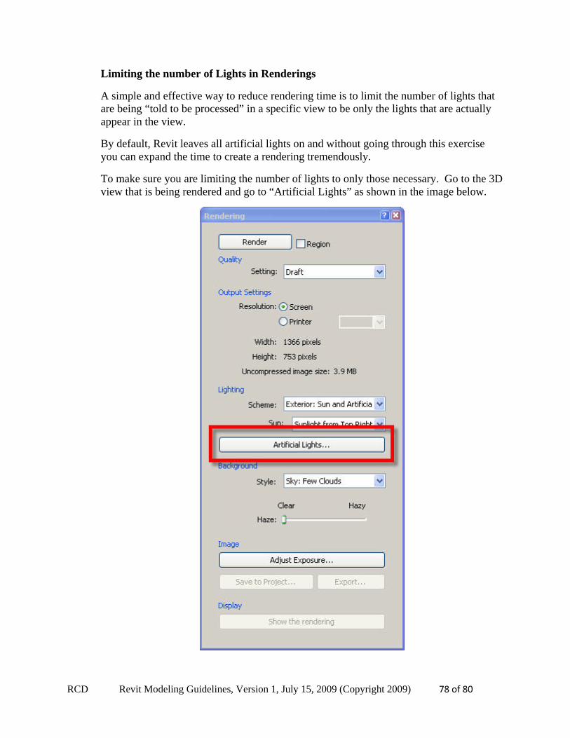
Limiting the number of Lights in Renderings
A simple and effective way to reduce rendering time is to limit the number of lights that are being “told to be processed” in a specific view to be only the lights that are actually appear in the view.
By default, Revit leaves all artificial lights on and without going through this exercise you can expand the time to create a rendering tremendously.
To make sure you are limiting the number of lights to only those necessary. Go to the 3D view that is being rendered and go to “Artificial Lights” as shown in the image below.
RCD Revit Modeling Guidelines, Version 1, July 15, 2009 (Copyright 2009) 79 of 80
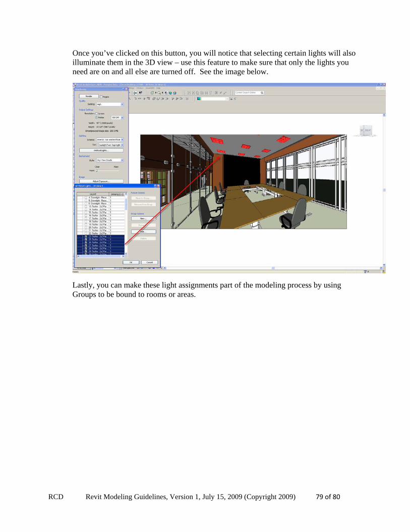
Once you’ve clicked on this button, you will notice that selecting certain lights will also illuminate them in the 3D view – use this feature to make sure that only the lights you need are on and all else are turned off. See the image below.
Lastly, you can make these light assignments part of the modeling process by using Groups to be bound to rooms or areas.
RCD Revit Modeling Guidelines, Version 1, July 15, 2009 (Copyright 2009) 80 of 80
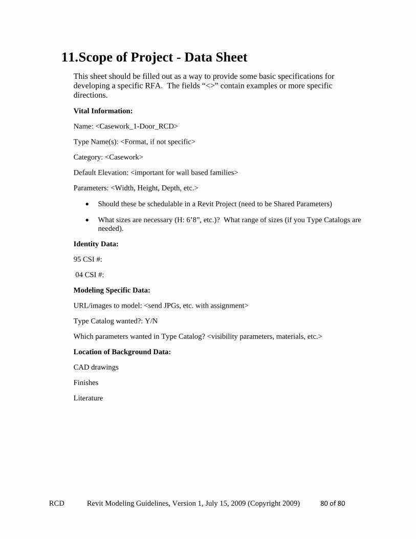
11. Scope of Project - Data Sheet This sheet should be filled out as a way to provide some basic specifications for developing a specific RFA. The fields “<>” contain examples or more specific directions.
Vital Information:
Name: <Casework_1-Door_RCD>
Type Name(s): <Format, if not specific>
Category: <Casework>
Default Elevation: <important for wall based families>
Parameters: <Width, Height, Depth, etc.>
Should these be schedulable in a Revit Project (need to be Shared Parameters)
What sizes are necessary (H: 6’8”, etc.)? What range of sizes (if you Type Catalogs are needed).
Identity Data:
95 CSI #:
04 CSI #:
Modeling Specific Data:
URL/images to model: <send JPGs, etc. with assignment>
Type Catalog wanted?: Y/N
Which parameters wanted in Type Catalog? <visibility parameters, materials, etc.>
Location of Background Data:
CAD drawings
Finishes
Literature


![Denon+RCD M33+RCD M35+DAB++Service+Manual[1]](https://img.pdfslide.tips/doc/110x75/552e5c474a7959485c8b493a/denonrcd-m33rcd-m35dabservicemanual1.jpg)