Embed Size (px)
Citation preview
I n d u s t r i a l C o n d e n s i n g U n i t s
Technical DataRefrigeration
w w w . d a i k i n . e u
ICU.pdf 1 26/01/2011 11:11:36
I n d u s t r i a l C o n d e n s i n g U n i t s
Technical DataRefrigeration
w w w . d a i k i n . e u
ICU.pdf 2 26/01/2011 11:11:42
��������� ����������������������
������������������ �
��������������� �������������������������
������������ ������ �
� ���������� �� ��� ���������� ����������������������������������������������� ��������������� ���������������������������������������������������������������������������������������������������������������� ���������������������������������������������������������������������������������������������������������������������������� �
� ��������������������������������������������������������������������������������������������������������������� !���������������"������������������������������������������������������������������������������������������������������� �����#���"������� ����������������������������������������������������������������������������������������������� $��������"���������������������������������������������������������������������������������������������������������������� %�&�� ���'������������� ����������������������������������������������������������������������������������������������� ()������� ���� ������������������������������������������������������������������������������������������������������ (%�&�� ������*������������������������������������������������������������������������������������������������������������������� +,����"�����-���������.�/����������������������������������������������������������������������������������������� +������������������ �0��"��!���� ��������������������������������������������������������������������� +����������������1������������������������������������������������������������������������������������������ 2
���������������������!�������������������� �������������������������������������������������� 3)���������� ���������������������������������������������������������������������������������������������������������������������� 3�������%������������������������������������������������������������������������������������������������������������������������� 4%�&�� �������������������������%��������������������������������������������������������������������� 4,��������������������������������������������������������������������������������������������������������������������� 4������!�&����"�����������"��������1��������������������������������������������������� 4
5 �����������6�� � ���������������������������������������������������������������������������������������������������� �7���"����������������������������������������������������������������������������������������������������������������������������� �71����8����*������������������������������������������������������������������������������������������������������ �7%��������� ���*��������"���"������� ��������������������������������������������������������� �7��������� �1�����*��������������������������������������������������������������������������������������������� �7����������1����������������������������������������������������������������������������������������������������������������� �����������������"���"������������������������������������������������������������������������������� �(,������������������������������������������������������������������������������������������������������������������ �2%�.���������$�������� ���������������������������������������������������������������������������������������������� �3
����������� ��
� ����� ������������������������������������������������������������������������������������������������������������������������ 5
� 0�������� ������������ �������������������������������������������������������������������������������������������� (
����������� �������������������������������������������������������������������������������������������������������������� +�����9��� ��������������������������������������������������������������������������������������������������������������������� 2
ICU.pdf 3 26/01/2011 11:11:42
��
��������� ����������������������
������������������
��������������� �������������������������
5 1���������������� �$��������������������������������������������������������������������������������� 3)���������������������������������������������������������������������������������������������������������������������������� 3��������������������������������������������������������������������������������������������������������������������������������� 4)�����$����� ��������������������������������������������������������������������������������������������������������������� 57�������$���������������������������������������������������������������������������������������������������������������������� 57
( ������������������������������������������������������������������������������������������������������������� 5����������1������������������������������������������������������������������������������������������������������������ 5������,��.��� ����������������������������������������������������������������������������������������������������������������� 5���������������"��� ����������������������������������������������������������������������������������������������� 5���"����������������������������������������������������������������������������������������������������� 5���"���������&������� ����������������������������������������������������������������������������������������� 5(��"����������"��� ���������������������������������������������������������������������������������������������������� 5(��"��������1����������������������������������������������������������������������������������������������������� 5+��"������������8���1���� ��� ������������������������������������������������������������������������� 5+��"�����������8��#��1���� ��� ������������������������������������������������������������������� 5+��"�������:��0����.����� ����*���������"�������������������������������������� 52������� ���"�������������������������������������������������������������������������������������������������� 52��"���������"���������� ��������� �������������������������������������������������������������������� 54��� ���������������������������������������������������������������������������������������������������������������� (7
+ �������*���������������������������������������������������������������������������������������������������������������� ( ������������������� ��������������������������������������������������������������������������������������������� ( ������������������������������������������������������������������������������������������������������������������������������� ( �������� ������� ���������������������������������������������������������������������������������������������������������� (5��"������������������������������������������������������������������������������������������������������������������ ((�������������� ��������������������������������������������������������������������������������������������������������������� ((���������������� ������������������������������������������������������������������������������������������������� (+�������"��;���� ��������������������������������������������������������������������������������������������������������� (+��������������������������������������������������������������������������������������������������������������������� (2)��"����������������������������������������������������������������������������������������������������������������������� (3
2 ����*�������""�������������������������������������������������������������������������������������� (4������������� ����������������������������������������������������������������������������������������������������������������� (4�� .���� ���������� ������*����.���������������������������������������������������������������� (4�� .���� ������������������*����.�������������������������������������������������������������� +��� .���� ����������������*����.�������������������������������������������������������������� +�
3 �������������� ������������������������������������������������������������������������������������������������������������ +
4 ���<������������������������������������������������������������������������������������������������������������������������ +(������������������� ������������������������������������������������������������������������������������������������������� +(��������������������������������������������������������������������������������������������������������������������� +(���<� �������������������������������������������������������������������������������������������������������������������������������� +2
ICU.pdf 4 26/01/2011 11:11:42
��������� ����������������������
������������������ ���
��������������� �������������������������
�����������������
� ).�����������.�������������������������������������������������������������������������������������������������� 4
� ������� �1������������������������� ������������������������������������������������������ 45)���8������1���������� ��������������������������������������������������������������������������������������������� 45,�������������������������������������������������������������������������������������������������������������������� 451������ ������������������������������������������������������������������������������������������������������������� 4(
1��������1��"���� ���������=���""�������� ����������������������������������������������������������������������� 4+
5 6����������������� ���������������������������������������������������������������������������������������������� 42�����9�� ������������������������������������������������������������������������������������������������������������������������ 42������������������������������������������������������������������������������������������������������������������������������ 42
( 1���������������������������������������������������������������������������������������������������������������� 43������� ������������������������������������������������������������������������������������������������������������������ 43�����,��.��� ����������������������������������������������������������������������������������������������������������������� 44������������������������������������������������������������������������������������������������������������������������������ �77��"����������������������� ����������������������������������������������������������������������������� �77��"��������%�� �������"���������������������������������������������������������������������������� �7���"��������%�� ����>����� �����&����� ����������������������������������������������� �7 ��"����������"��� �������������������������������������������������������������������������������������������������� �7(��"���������&������� ��������������������������������������������������������������������������������������� �7(��"��������%�"����� ������������������������������������������������������������������������������������������������ �7(��"��������1����������8�1��������!����������������������������������������������������������� �7+��"��������1����������8�$�������%�*��#���� ����������������������������������������� �7+������������ ��������������������������������������������������������������������������������������������������������������� �7+��� ������1�������������� ������������������������������������������������������������������������������� �7+%�&�� ���'������������������������������������������������������������������������������������������������������������������ �74
+ ���"������������������������������������������������������������������������������������������������������� ��7
2 )��������� ����������������� �$������ ������������������������������������������� ��5)�������$������������������������������������������������������������������������������������������������������������ ��5�������$������������������������������������������������������������������������������������������������������������������� ��5)������������� ��������������������������������������������������������������������������������������������������������� ��(������������� ���������������������������������������������������������������������������������������������������������������� ��(
3 �������������� ���������������������������������������������������������������������������������������������������������� ��+?���� ���������������������������������������������������������������������������������������������������������������������������� ��2?���� ��������� ������������������������������������������������������������������������������������������������������ ��2������� ����<�%������������ ������������������������������������������������������������������������� ��3@�*������� ��������������������������������������������������������������������������������������������������������������������� ��3
ICU.pdf 5 26/01/2011 11:11:42
��
��������� ����������������������
������������������
��������������� �������������������������
��������������������������������������������������������������������������������������������������������������������� ��41���#�� ���������������������������������������������������������������������������������������������������������������������� ��7
4 )��"���.8"��� ���������������������������������������������������������������������������������������������������� ��50��#�)���*��)��"���������������������������������������������������������������������������������������������������� ��50��#�)��"�%�� ���������������������������������������������������������������������������������������������������������� ��(
�7 0���#��.8"������������������������������������������������������������������������������������������������������ ��2���������������������� ���������������������������������������������������������������������������������������� ��2
�� ���������.8"������������������������������������������������������������������������������������������������� ��4����������������������������������������������������������������������������������������������������������������������������� ��4��"��������������� ����������������������������������������������������������������������������������������������� � ������������ ��������������������������������������������������������������������������������������������������������������� � )��"��������������������������������������������������������������������������������������������������������������������� � 2
�� �������������.8"�������������������������������������������������������������������������������������� � 30��#�������������1���"�������������������������������������������������������������������������������� � 3����������������������������������������������������������������������������������������������������������������� � 3��������������.�� ������������������������������������������������������������������������������������������������� �57������!�������� ������������������������������������������������������������������������������������������������������� �57@�".��������"���������������������������������������������������������������������������������� �5�
� ������� ����<�%����������������������������������������������������������������� �5�������� ��.8"����������������� ����������������������������������������������������������� �5 )���*��)��"�������������� ����������������������������������������������������������������������������� �55)��"�%���������������� ���������������������������������������������������������������������������������� �530��#���������������<�%��� �������������������������������������������������������������������������������� �540��#���"��������A�����������<�%����������������������������������������������������������� �540��#���"��������A�����������<�%����������������������������������������������������������� �(70��#��������>�$����������<�%������������������������������������������������������������������������� �(���"�������������������<�%��� ���������������������������������������������������������������������� �(�)��"������������<�%��������������������������������������������������������������������������������������� �( ������������������������������<�%��� ���������������������������������������������������������� �(5������������������������<�%������������������������������������������������������������������������ �((�������� ��������������������<�%��� ��������������������������������������������������������� �((������������������������<�%��� ������������������������������������������������������������������� �(3�������"����� ��������������<�%��� ����������������������������������������������������� �(4���������������� ����� ��������������<�%�������������������������������� �+7��������<���������������������������������������������������������������������������������������������������������� �+�0��#�������������1���"���������<�%����������������������������������������������������� �+������������������������<�%��� ��������������������������������������������������������������������� �+���������������.������<�%��� ������������������������������������������������������������������������ �+5
ICU.pdf 6 26/01/2011 11:11:42
��������� ����������������������
������������������ �
��������������� �������������������������
�5 ������������������������������������������������������������������������������������������������������������������������� �+(0��#����������������������������������������������������������������������������������������������������������� �+(������������������������������������������������������������������������������������������������������������� �+(������������������������������������������������������������������������������������������������������������������ �++�������� �������������������������������������������������������������������������������������������������� �++��"��������������� ����������������������������������������������������������������������������������������������� �+3�������������������� �������������������������������������������������������������������������������������������� �27�������"����� ���������������������������������������������������������������������������������������� �2����������������� ����� ���������������������������������������������������������������� �2���������<���������������������������������������������������������������������������������������������������������� �2�)��"��������������������������������������������������������������������������������������������������������������������� �2������������������������������������������������������������������������������������������������������������������ �2���������!����������������������������������������������������������������������������������������������������������������� �25
�( )��"���� ����������������������������������������������������������������������������������������������������������� �2()��"������ ����������������������������������������������������������������������������������������������������������������� �2(����������)��"����������������������������������������������������������������������������������������������������������� �2(��"�������������)��"� ���������������������������������������������������������������������������������������� �22�����"������$���)��"������������������������������������������������������������������������������������������ �37,B������)��"������������������������������������������������������������������������������������������������������������� �3�)��"�)�<��#� ��"������������������������������������������������������������������������������������������ �3�)��"�%���!���� �������������������������������������������������������������������������������������������������������� �3�
�+ �������������� �������������������������������������������������������������������������������������� �3 ���������������������������������������������������������������������������������������������������������������������������� �3 ����<������ �!�����"������������"�9��<8���9������ ������������������������� �3 �����!�����"������������������������������������������������������������������������������������������������������� �35�����1����������������������������������������������������������������������������������������������������������������������� �3(
�2 ���#����0�������� ������������ ������������������������������������������������������������������� �3+
�3 ��""�������������������������������������������������������������������������������������������������������������� �321��������������� ������������������������������������������������������������������������������������������������� �32��""������������� ������������������������������������������������������������������������������������������� �32�� �"���������������������������������������������������������������������������������������������������������������������������� �32�� .���) �����������������0����.������������������������������������������������������������ �33�� .���) ������������������0����.���������������������������������������������������������� �47�� .���) ����������)�������0����.����������������������������������������������������� �4�
�4 )���� �B�����������!���� ������������������������������������������������������������������������� �4������@�".���!���� ��������������������������������������������������������������������������������������������� �4��������������������������������!���� ������������������������������������������������������ �4�
ICU.pdf 7 26/01/2011 11:11:42
��
��������� ����������������������
������������������
��������������� �������������������������
��������������������$����������>!����*����$��%�*�� ����������������������������������������������������������<5��������������� ���������"��B�#����C�D�,����
�� ���������� ������������ �����������������������������������������������������������������������<�3���� ��������&����"���� ��������������������������������������������������������������������������������������<� ����5�6�������������"��� �����������������������������������������������������������������������������������<�2����(���#��� �������"��������� �����"���������������������������������������������������������<�4����+���#��� �������"��������� �����"����
���������"�������������-�������/ ����������������������������������������������������������<� 7����2���#��� �������"��������� �����"����
�����&�� ���'�������-�������/� ������������������������������������������������������������������< �
����������������.�������:��"���"�"������������ ���������������������������������������������������������������<�+��.������� �� ��������"�����������������������������������������������������������������<�����.�� ���� �� �%�#���"������������������������������������������������������������������<�����.��5���"���������� �E�����������������������������������������������������������������������������<�� ��.��(�,����"��� ��������"�������������� ��������������������������������������������<��5��.��+�,����"��� �%�#���"�������������� ���������������������������������������������<��(��.��2�,����"��� �%�#���"�������������� ���������������������������������������������<��(��.��3���"���������� �E����� ������������������������������������������������������������������������<��+��.��4�%�&�� ������*���������������������������������������������������������������������������������� ����+
ICU.pdf 8 26/01/2011 11:11:43
��������� ����������������������
������������������ �
1. The Hall Standard Industrial Condensing Unit
J & E Hall International set out to meet the demand for a range of standard screw compressor package units which combine the economic use of energy with design flexibility and reliability. These essential criteria are realised in the Industrial Condensing Units (ICU), the most advanced design available in oil injected single screw refrigeration technology with air cooled condenser that are ready to install in a wide range of different applications.
Incorporated in the ICU package design, are several novel features for energy saving, together with the proven efficiency and dependability of the advanced HallScrew single screw compressor. Thousands of HallScrew compressors are now operational in units installed in many countries all over the world, and have earned an excellent reputation in the fields of refrigeration, air conditioning and heat recovery.
These factory-built industrial condensing units are easy to install. They include air cooled condenser, HallScrew compressor, oil separator, liquid receiver, filter drier and are fully wired with all motor starters and controls. Only the mains electrical supply, start-stop signal wiring and interlocking with process is required on site.
With a small footprint the units can be installed where there isn’t space available to install a plant room. If there is room for an air cooled condenser, there is room for the ICU.
The units offer great value for money with up to 30% less than the cost of the equivalent site installed system.
1.1. Main Features
• Flexible operation thanks to the Variable Speed Drive capacity control to eliminate energy wastage.
• Fitted with a microprocessor based MicroTech II controller, incorporating a PID control algorithm for close control of the set point pressure
• Oil injection by system pressure difference, no continuously running oil pump – hence, energy savings
• Economiser option providing substantial capacity increase and improved energy efficiency, especially at low evaporating temperatures. Combined with VSD controls the economiser option gives the best part load performance operation
• Space saving construction due to the compact design of the condenser coils (‘W’ configuration)
• Low noise levels down to 75 d(B)A or 80 d(B)A at 1 meter for standard option
• 100% standby compressor capacity for critical cooling system (for “one run – one standby compressor” units)
• High ambient operation. The units are designed for 35°C dry bulb but will operate in ambient up to 38°C (at reduced cooling capacity)
• The units are also easy to maintain. External oil filters and filter driers can be replaced without turning off the compressors. Isolating and drain valves allow the oil filter cartridges to be changed within minutes.
ICU.pdf 9 26/01/2011 11:11:43
�
��������� ����������������������
������������������
• Liquid receiver is sized to allow refrigerant pump down for most systems
• Design and manufacture complies with BS EN 378: 2008. CE marking complies with The Supply of Machinery (Safety) Regulations: The Pressure Equipment Directive (PED) Survey by customer’s appointed independent inspection authority can be arranged
• Manufactured and assembled to J & E Hall International standards, this product comes fully warranted and backed by our expertise derived from 200 years in engineering and over a 100 years experience in refrigeration.
1.2. Scope of supply
Standard features for the Air Cooled Condensing Unit include the following:
• HallScrew single screw compressor(s).
• Vertical oil separator with dual safety pressure relief valves.
• Air cooled condenser
• Condensing pressure control
• Large liquid receiver with dual safety pressure relief valves
• A filter drier after the liquid receiver with isolating valves
• Liquid sightglass with moisture indicator
• Suction and delivery isolating valves
• Pressure transducers for LP and oil pressure cut out
• Starter and control panel (suction pressure control) incorporating electronic controller suitable for remote monitoring via modem or GSM supervision program
• Oil injected screw compressor for maximum reliability.
• Two oil filters with isolating valves
• Variable speed drive for capacity modulation
• Internal suction/discharge safety relief valve
• High pressure safety cut-outs
• Thermistor high temperature protection to motor
• Thermistor discharge gas high temperature protection
• Oil level sensor
• Liquid Injection Oil Cooling
• Economiser facility provided to improve operating efficiency, especially at low suction gauge (as an option).
For further information refer to publication 2-129 Economiser Facility for HallScrew Compressors.
ICU.pdf 10 26/01/2011 11:11:43
��������� ����������������������
������������������ �
2. Description of Operation
The description which follows is included to impart a basic understanding of how the plant functions before describing its construction in detail.
2.1. Refrigerant System
Refer to flow and instrumentation diagram Fig 5,6 and 7.
The HallScrew compressors act as gas pumps, drawing slightly superheated low pressure refrigerant gas from the suction line, compressing it and discharging superheated high pressure gas into the air cooled condenser via the oil separator.
All the oil injected into the compressors for lubrication, sealing and cooling ends up in the discharge gas stream. The oil separator removes most of the oil from the gas and returns the oil to the lubrication circuit.
The discharge gas enters the air cooled condenser where the gas is first desuperheated and then condensed as it passes through the air-cooled condenser coils. The liquefied refrigerant flows out of the condenser into the liquid line. At this point the refrigerant is in its liquid phase, at high pressure and slightly subcooled.
The liquefied refrigerant drains down to the liquid receiver which acts as a reservoir for surplus charge during evaporator defrost or pump down.
The liquid refrigerant flows through a filter/drier where any moisture and/or dirt are removed before flowing to the liquid line:
• If used - the economiser with subcooled liquid flowing to the evaporators (by others).
The pressure, and hence the temperature of the liquid refrigerant in the evaporators is maintained at its low level by the compressor, drawing the vapour into and through the suction line, the process being a continuous. Design of the evaporator and refrigerant controls must ensure that the suction vapour is in a superheated condition when it reaches the compressor.
2.2. HallScrew Compressor
J & E Hall air-cooled Industrial Condensing Units (ICU) use the HallScrew HSML 3100 semi-hermetic compressors with a wide range of cooling capacities with up to 164 kW (220 hp) of installed power.
HSM 3100 series compressors are capable of operating without cooling over a limited range, but when indicated, a suitable cooling system is required (refer to the selection table).
The compressors are of the positive displacement, single screw semi-hermetic type driven by an integral stator/rotor (motor) unit with Variable Speed Drive.
A separate instruction manual has been prepared detailing the construction and operation of the HallScrew compressor. It is essential to have a copy of this publication - the HallScrew Operators and Application Manuals - as reference is made to it throughout this publication.
2.3. Oil Management
The method of oil separation utilised by the oil separator is achieved by a vertical vessel with mesh pad, two sight glasses, heater, dual safety pressure relief valve and oil flow sensor.
ICU.pdf 11 26/01/2011 11:11:43
�
��������� ����������������������
������������������
Deciding the required level of efficiency is important and is dependant not only on the compressor but also on the system design. No oil separator is 100 % efficient and some oil will always be carried over into the system. On a small direct expansion system this oil will be rapidly recirculated back to the compressor travelling with the refrigerant through the system and returning via the suction line. Sufficient oil need to be maintained in the oil separator to ensure an adequate level of oil to match the specified oil flow rate from the separator into the compressor.
Note: In systems such as those incorporating flooded evaporators where oil carried over from the separator is not so readily or quickly returned, greater care is required of the system design to achieve oil return to the compressor. For the systems with long liquid and suction lines the oil charge must be increased.
For each compressor, a solenoid valve is provided in the oil injection line. The solenoid valve is electrically interlocked to energise (open) when the compressor starts and de-energise (closed) when the compressor stops.
For each compressor, a stop/check valve is provided in the discharge line before the inlet to the oil separator. This dispenses with the need for a suction non-return valve.
2.3.1. Oil Separator/Reservoir
This is a vertical vessel which removes most of the entrained oil from the discharge gas.
As the discharge gas/oil mixture enters the separator there is a sudden change of velocity and direction which removes large droplets of entrained oil. The mixture flows through a knitted wire mesh pad insert where the remaining oil mist forms large droplets on the wire strands; these droplets fall under gravity to the bottom of the separator.
Oil removed from the discharge gas drains into the lower portion of the separator shell which is used as an oil reservoir. The oil level can be observed through the oil level sight-glasses.
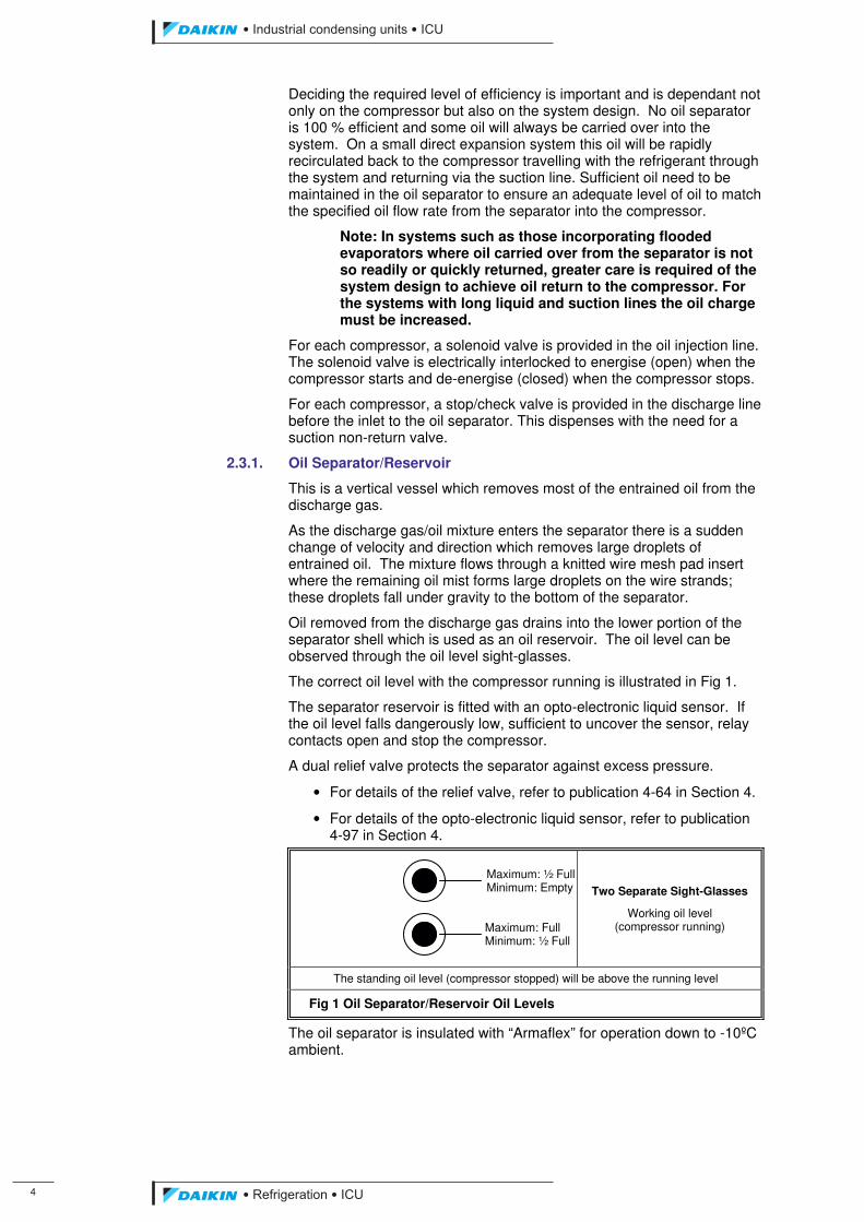
The correct oil level with the compressor running is illustrated in Fig 1.
The separator reservoir is fitted with an opto-electronic liquid sensor. If the oil level falls dangerously low, sufficient to uncover the sensor, relay contacts open and stop the compressor.
A dual relief valve protects the separator against excess pressure.
• For details of the relief valve, refer to publication 4-64 in Section 4.
• For details of the opto-electronic liquid sensor, refer to publication 4-97 in Section 4.
Two Separate Sight-Glasses
Working oil level (compressor running)
The standing oil level (compressor stopped) will be above the running level
Fig 1 Oil Separator/Reservoir Oil Levels
The oil separator is insulated with “Armaflex” for operation down to -10ºC ambient.
Maximum: ½ Full Minimum: Empty
Maximum: Full Minimum: ½ Full
ICU.pdf 12 26/01/2011 11:11:43
��������� ����������������������
������������������ �
2.3.2. Oil Filter
Two oil filters (one run - one standby) with a micronic, disposable, paper element cleans the oil before it enters the compressor. Isolating valves and a pressure release allow easy renewal of the filter element without switching the unit off.
• For details of the oil filter, including the procedure for changing the filter element, refer to publication 4-115 in Section 4.
2.3.3. Oil Heater
The separator is fitted with an oil heater of sufficient capacity to maintain an oil temperature minimum 20 °C above the ambient temperature, thereby preventing refrigerant migration into the oil and the resultant loss of viscosity and potential foaming. The oil heater is also electrically interlocked to energise when the compressor stops to prevent refrigerant condensing in the oil body.
2.3.4. Oil Low Level
An opto-electronic liquid sensor is fitted to the oil separator at a point corresponding to a dangerously low oil level. The sensor is electrically interlocked to prevent the compressor starting unless there is sufficient oil in the reservoir, and stop the compressor if the oil level falls below the danger level.
2.3.5. Oil High Level Sensor
Level sensor is fitted to the compressor casing at a point corresponding to a dangerously high oil level. The sensor is electrically interlocked to prevent the compressor starting if the oil level exceeds the danger level.
2.3.6. Lubricating Oils
The choice of lubricant depends on the refrigerant, the type of system and the operating conditions.
For applications using HFC refrigerants, ester lubricants will be used.
Refer to the J & E Hall publication 2-59 Approved Oils.
2.4. Liquid Injection Control
The temperature of the discharge gas/oil mixture is maintained at a constant level by the evaporation of liquid refrigerant, this is injected into the compressor via an electronic expansion valve controlled from the discharge temperature. The injection valve effectively ensures that the temperature of the oil for injection, and more especially for compressor bearing and gland seal lubrication remains within the design limits.
Liquid injection is used for all the units. A thermostat is used to open/close an electronic expansion valve in the liquid injection line according to changes in discharge temperature. The thermostat is set to open the expansion valve when discharge temperature rises to 95 °C (max) and close when the temperature falls to 85 °C.
Also a strainer and sight-glass for visual indication that liquid is present, are provided in the liquid injection line.
2.5. Air Cooled Condenser
Industrial Condensing Units are constructed with internally enhanced seamless copper tubes arranged in a staggered row pattern and mechanically expanded into lanced and rippled aluminium condenser fins with full fin collars.
ICU.pdf 13 26/01/2011 11:11:43
�
��������� ����������������������
������������������
The condenser fans are helical type with wing-profile blades for achieving better performance. Each fan is protected by a guard. The motors are IP54. Fans thermal overloads are supplied as standard.
2.6. Liquid Receiver
Liquid refrigerant (condensate) from the condenser drains down into the liquid receiver.
The liquid receiver acts as a reservoir for surplus refrigerant, and is sized to hold the majority of the system charge when it is necessary to pump-down prior to opening up part of the system.
A dual relief valve protects the liquid receiver against excess pressure.
• For details of the relief valve, refer to publication 4-64 in Section 4.
2.7. Economiser (if applicable)
The system is supplied with direct expansion plate heat exchanger.
Economiser works as a subcooler. Liquid is being expanded in evaporator by electronic expansion valve, after evaporation process refrigerant flows through a non-return valve and filter strainer to economiser port located on the side of the compressor.
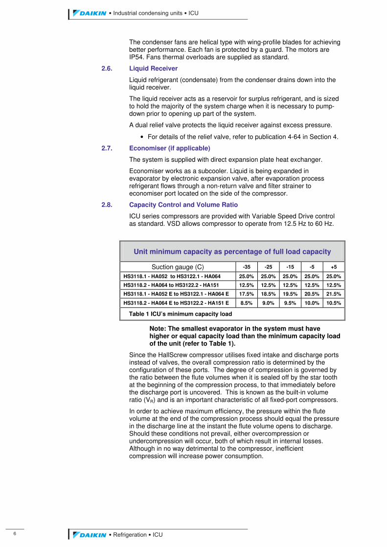
2.8. Capacity Control and Volume Ratio
ICU series compressors are provided with Variable Speed Drive control as standard. VSD allows compressor to operate from 12.5 Hz to 60 Hz.
Unit minimum capacity as percentage of full load capacity
Suction gauge (C) -35 -25 -15 -5 +5
HS3118.1 - HA052 to HS3122.1 - HA064 25.0% 25.0% 25.0% 25.0% 25.0%
HS3118.2 - HA064 to HS3122.2 - HA151 12.5% 12.5% 12.5% 12.5% 12.5%
HS3118.1 - HA052 E to HS3122.1 - HA064 E 17.5% 18.5% 19.5% 20.5% 21.5%
HS3118.2 - HA064 E to HS3122.2 - HA151 E 8.5% 9.0% 9.5% 10.0% 10.5%
Table 1 ICU’s minimum capacity load
Note: The smallest evaporator in the system must have higher or equal capacity load than the minimum capacity load of the unit (refer to Table 1).
Since the HallScrew compressor utilises fixed intake and discharge ports instead of valves, the overall compression ratio is determined by the configuration of these ports. The degree of compression is governed by the ratio between the flute volumes when it is sealed off by the star tooth at the beginning of the compression process, to that immediately before the discharge port is uncovered. This is known as the built-in volume ratio (VR) and is an important characteristic of all fixed-port compressors.
In order to achieve maximum efficiency, the pressure within the flute volume at the end of the compression process should equal the pressure in the discharge line at the instant the flute volume opens to discharge. Should these conditions not prevail, either overcompression or undercompression will occur, both of which result in internal losses. Although in no way detrimental to the compressor, inefficient compression will increase power consumption.
ICU.pdf 14 26/01/2011 11:11:43
��������� ����������������������
������������������ �
In the Industrial condensing Units there are two types of VR:
• 4.9 for low temperature units, using HSL 3100 compressors with range of temperatures varying from -40ºC to -25ºC
• 3.0 for high temperature units, using HSM 3100 compressors with range of temperatures varying from -24ºC to 0ºC
Note: For both of VR there is need to use adjustable MOP metering devices in the process side.
2.9. MicroTech II C Plus Controller
MicroTech II C Plus controller is installed as standard; it can be used to modify unit set-points and check control parameters. A built-in display shows machine's operating status, programmable values, set-points, like temperatures and pressures of refrigerant and air. Device controls maximise the unit’s energy efficiency and the reliability. A sophisticated software with predictive logic, select the most energy efficient combination of compressors and condenser fans to keep stable operating conditions and maximise energy efficiency. The compressors are automatically rotated to ensure equal operating hours.
MicroTech II C Plus protects critical components in response to external signals from its system sensors measuring: motor temperatures, refrigerant gas and oil pressures, correct phase sequence.
For further information refer to the Controller Operating Manual.
ICU.pdf 15 26/01/2011 11:11:43
�
��������� ����������������������
������������������
3. Integration into the Refrigeration Circuit
The compressor is an oil injected screw type. For HS L/M 3100 series compressors, the system contains an oil separator of sufficient capacity. The system is designed to return any oil carried over into the system from the separator, back to the compressor.
The suction return to the compressor must be dry gas in order to achieve full performance. Liquid return will be detrimental to performance although unlike reciprocating compressor is not harmful to the compressor in small quantities. However large quantities of liquid or oil returned to the compressor via the suction line can form an incompressible fluid in the rotor flutes with resultant damage to the compressor. Thus the system must be designed to prevent such occurrences.
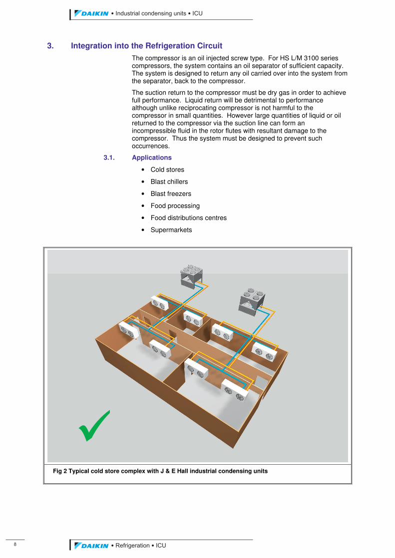
3.1. Applications
• Cold stores
• Blast chillers
• Blast freezers
• Food processing
• Food distributions centres
• Supermarkets
Fig 2 Typical cold store complex with J & E Hall industrial condensing units
ICU.pdf 16 26/01/2011 11:11:43
��������� ����������������������
������������������ �
3.2. Suction Line
The suction line should be designed to allow any build up of liquid to drain back to the evaporator. Refrigerant gas velocities should be sufficient to ensure recirculating oil is returned to the compressor.
3.3. Liquid Separation in the Suction Line
If liquid is present in the suction line due to excessive carry over from the evaporator and velocities are low, separation of the liquid can occur. If U-bends are present in the suction line liquid can collect in these traps. If the flow rate is suddenly increased (due to sudden increase in compressor load) then this liquid can be carried through to the compressor as a slug. It is these large erratic slugs of liquid that are detrimental to the compressor rather than constant small amounts of liquid return.
3.4. Electrical connections
The ICU has 3 electrical connections:
• Remote on/off
• External alarm link – for user alarm system
• Unit’s remote alarm signal link for tripping
Compressor motor and discharge high temperature thermistors are fitted as standard.
3.5. Safety Requirements for Compressor Protection
There are a number of system pressures and temperatures which must be monitored to protect the compressor and obtain an overall view of performance.
ICU.pdf 17 26/01/2011 11:11:43
�
��������� ����������������������
������������������
4. Installation Guide
The following section has been prepared as a response to the many questions regularly asked about installing and applying our equipment. Much of the following information also appears in the instruction manuals for the HallScrew compressor and the Pack, but experience has shown that installers and users, perhaps unfamiliar with this equipment, require this information before the unit is shipped.
4.1. Shipment
Before dispatch from the factory, all connections on the compressor package unit are either blanked or valved off before charging with dry nitrogen or refrigerant to a pressure of approximately 1 bar g. The evacuation process removes air and moisture, while the ‘holding charge’ maintains the system in this condition until it is time to install the unit.
CAUTION Stop valves and blanked pipe line connections must not be opened or tampered-with, otherwise the factory installed holding charge of nitrogen (and lubricating oil, if supplied) may be lost.
Packaged units and other items of plant which will eventually come into contact with refrigerant should arrive on site clean, dry and tightly sealed. If components do not arrive in this condition, the installer must notify J & E Hall International, and provide full details of the problem.
4.2. Post - Delivery Inspection
Upon receipt of plant components it is important to make an immediate inspection of the equipment in the presence of the carrier’s representative, in case of damage which may have occurred during transit. If any damage is found, a notation should be made on the delivery receipt before signing, and a claim filed against the delivering carrier. It is the carrier’s responsibility to pay for any shipping damages. Check the contents of the shipment against the items listed on the advice note. Any shortages must be reported to J & E Hall International, without delay. When checking the compressor package unit, make sure the holding charge has been retained during transit from the factory. If pressure gauges register zero there is a leak which must be traced and repaired, that part of the system leak tested, evacuated and a fresh holding charge inserted.
4.3. Lifting and Moving System Components
System components are stringently tested before leaving the factory where every precaution is taken to ensure that equipment is dispatched to the customer in perfect condition. It is very important that installation personnel adopt the same standards of care when unpacking and handling. Care must be taken when off-loading and positioning the compressor package unit and other large system components. Chains, cables or other moving equipment must be positioned so as to avoid damage to the component being handled; the use of load spreaders or a lifting frame is recommended where appropriate. Do not attach hoists or slings to the pipework. Shock-loads or other rough handling should be avoided as this treatment may result in damage to equipment, or misalignment of the various subassemblies.
4.4. Storage and Preservation
If the plant is not to be installed immediately but held in store, the following points must be observed:
ICU.pdf 18 26/01/2011 11:11:43
��������� ����������������������
������������������ ��
4.4.1. Store Location Plant should preferably be stored indoors in an unoccupied area which should be clean and vermin-free, with a warm, dry environment, well ventilated to discourage condensation. If the equipment is stored outside, protection from the elements must be provided which also keeps condensation to a minimum. The compressor and other packaged components must be positioned on a level floor with reasonable access around all four sides to enable periodic inspections to be made. The underlying floor must be capable of safely supporting the weight of the equipment. Items of equipment fitted with rolling element bearings, for example, the compressor, drive motors and pumps, should be stored away from sources of vibration or isolated using anti-vibration packing; this will prevent fretting corrosion (Brinelling) of the bearings. Provision must be made for access to drive motors and pumps to enable the shafts to be rotated at weekly intervals. Programmed integrated circuits (memory chips) are sensitive to low temperatures. Equipment containing these devices, for example, the MicroTech II controller, should not be exposed to ambient temperatures below -10 °C.
The store area must be secure against unauthorised access. This is important to prevent vandalism or accidental damage and serious or fatal injury caused, for example, by the escape of refrigerant or oil.
4.4.2. Protection During Storage
Cover the ventilation grills of electric motors and electrical control panels to prevent condensation and discourage dirt, dust and small creatures from entering; make sure these covers are removed at the end of the storage period. External unpainted metal surfaces, for example, the drive motor shaft extension or the exposed portion of a valve spindle, should be protected by coating with Shell Enis Fluid MD or a thin film of grease. Every six months check the protective coating and reapply as necessary. Carry out any additional special instructions for the long term storage of the following plant components:
• HallScrew compressor; carry out the procedure described under Placing the Compressor into Store in the compressor instruction manual.
• Compressor drive motor; refer to the manufacturer’s Instructions.
4.4.3. Storage Inspection Routine
At least once a week:
• Inspect the plant for signs of damage or deterioration.
• Check that the compressor package unit has retained its holding charge of nitrogen or refrigerant. Pressure gauges, where fitted, will show if there has been a decrease in pressure. Check any other packaged items which contain a holding charge.
Remember that significant changes in ambient temperature will cause the pressure of the holding charge to fluctuate. This should be taken into account if, because of a drop in pressure, a leak is suspected.
• Rotate drive motors and pumps by several turns. Shafts must be left in a different position each time they are rotated.
ICU.pdf 19 26/01/2011 11:11:43
��
��������� ����������������������
������������������
4.4.4. Taking the Plant out of Storage
Clean off the grease from bare metal surfaces or, if Shell Enis Fluid MD was used, use white spirit or similar solvent to remove the protective film. Carry out the procedure described under taking the Compressor out of Storage in the HallScrew compressor instruction manual. Carry out any additional special instructions for taking the plant components described in 4.4.2. out of storage.
4.5. Siting the Plant
When siting the plant, consideration should be given to the following:
a) Certain parts of the plant generate heat during operation, for example, the compressor package unit and electrical panels. These items of plant must be installed in a location which is well ventilated to ensure adequate dissipation of heat.
b) All parts of the plant should be positioned or protected to minimise the risk of impact damage, for example, by fork lift trucks.
c) Adequate working space should be provided on all sides and above plant components to allow for operation and maintenance, for example:
• access to instrumentation;
• access to stop valves, particularly isolating valves;
• changing filters, cleaning strainers;
• lubrication: grease nipples, oil filling connection;
• service pipe connections, for example, vent and drain lines;
Refer to the certified general arrangement drawing to establish the access required, pipe connections and sizes.
d) If the plant is accessible to unauthorised persons, steps must be taken to prevent access. This is to prevent vandalism or accidental damage, and serious or fatal injury, for example, from live terminals within electrical panels, or escape of refrigerant or oil.
ICU’s are air-cooled, hence it is important to observe the minimum distances which guarantee the best ventilation of the condenser coils. Limitations of space reducing the air flow could cause significant reductions in cooling capacity and an increase in electricity consumption.
To determinate unit placement, careful consideration must be given to assure a sufficient air flow across the condenser heat transfer surface. Two conditions must be avoided to achieve the best performance: warm air recirculation and coil starvation.
Both these conditions cause an increase of condensing pressures what results in reductions in unit efficiency and capacity. ICU performance is less affected in poor air flow situations because of its special condensing coil geometry.
Moreover the microprocessor has the ability to calculate the operating environment of the condensing unit and the capacity to optimize its performance staying on-line during abnormal conditions.
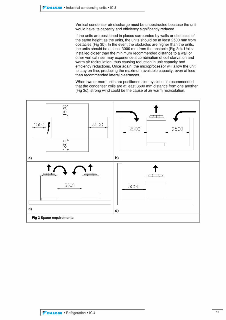
Each side of the unit must be accessible after installation for periodic service. Fig 3a shows you a minimum recommended clearance requirements.
ICU.pdf 20 26/01/2011 11:11:43
��������� ����������������������
������������������ ��
Vertical condenser air discharge must be unobstructed because the unit would have its capacity and efficiency significantly reduced.
If the units are positioned in places surrounded by walls or obstacles of the same height as the units, the units should be at least 2500 mm from obstacles (Fig 3b). In the event the obstacles are higher than the units, the units should be at least 3000 mm from the obstacle (Fig 3d). Units installed closer than the minimum recommended distance to a wall or other vertical riser may experience a combination of coil starvation and warm air recirculation, thus causing reduction in unit capacity and efficiency reductions. Once again, the microprocessor will allow the unit to stay on line, producing the maximum available capacity, even at less than recommended lateral clearances.
When two or more units are positioned side by side it is recommended that the condenser coils are at least 3600 mm distance from one another (Fig 3c); strong wind could be the cause of air warm recirculation.
a)
b)
c)
d)
Fig 3 Space requirements
ICU.pdf 21 26/01/2011 11:11:43
��
��������� ����������������������
������������������
4.5.1. Installing Packaged Components
The following paragraphs refer to the compressor but also apply, in general terms, to other packaged components installed on a baseframe.
4.5.1.1 Foundations
Firm, robust foundations are essential to support the weight of the compressor package unit. Early consideration should be given to the design of adequate foundations in order to achieve these aims; in addition, the amount of extra work required at a later date will be minimised. If the unit is intended for use with an existing installation, inspect the foundations and make any reinforcements which may be necessary.
A concrete foundation is generally considered most suitable, alternatively, installation on a steel floor will be adequate provided the surrounding structure has been sturdily constructed; a flimsy girder framework, for example, would not be suitable. Wooden floors are also satisfactory if they are laid over a concrete or steel base.
The concept of the screw compressor reduces noise and keeps vibration levels to a minimum. This means that anti-vibration mountings can be dispensed with in the majority of cases. However, if the unit is to be installed on a steel foundation, it may be worth considering fitting antivibration mountings in order to keep noise and vibration transmission to the surroundings as low as possible. Vibration isolators should be fitted in accordance with manufacturer’s instructions.
Concrete foundations should be generously dimensioned and adequately reinforced. Where conditions permit, a concrete plinth is recommended so as to raise the equipment above the surrounding floor level and provide adequate drainage. If underlying floor conditions are unfavourable, or in the event of an insufficiently rigid floor, seek the advice of an Architect or Civil Engineer concerning the design of a suitable foundation.
The cavities required for foundation bolts are normally pre-cast into a concrete base; leave a rough finish to the walls of the cavities so as to provide a good key for the grout mixture. Cavities may also be formed with a pneumatic drill after the base has been cast.
4.5.1.2 Installation Onto Prepared Foundations
The following paragraphs refer to installations made on concrete as this is probably the most common foundation material; however, these notes are equally applicable to an installation made on a steel floor.
The foundation immediately beneath the package unit mounting positions must be made smooth and even to accept packing pieces large enough to extend over the whole area of each mounting pad. Proceed by grouting in the foundation bolts level with the surface of the foundations. Before applying the grout mixture, make sure the cavities in the foundation are dirt and dust-free. To encourage a superior bond between the grout and foundation, apply a cement wash to the inside of the cavities approximately 30 minutes before grouting. Always use a fresh grout mixture, a proportion of one part sand to one part cement is recommended. Allow the grout to set hard.
Lower the package unit into position on the prepared foundation. The unit baseframe should be levelled by adjusting as required at each mounting position, checking at each stage with a long-base spirit level. When the package unit is square and level, insert metal packers of the required thickness under the mounting positions. As far as possible, the number of packing pieces at each position should be kept to a minimum. Secure the unit in position.
ICU.pdf 22 26/01/2011 11:11:43
��������� ����������������������
������������������ ��
4.6. Connecting System Components
After installing the packaged subassemblies onto prepared foundations, they must be coupled together to form a complete refrigeration system. When fabricating interconnecting pipework and making connections, every precaution must be taken to prevent dust, dirt or moisture entering the system. Packaged items of the plant and other major system components, which have been evacuated and are supplied complete with a holding charge, should remain in this clean, moisture-free condition until immediately before they are coupled to the rest of the system. Refer to Part E: Evacuation and Dehydration of The Operating Manual.
NOTE: for trouble-free operation of the plant, complete cleanliness and dryness of the refrigeration system is of the utmost importance.
4.6.1. Pressure Equipment Directive (PED)
This directive applies to pressure equipment (refrigeration plant) and assemblies within the European Economic Area (EEC). PED – 97/23/EC becomes mandatory on 29/05/2002.
CAUTION Industrial Condensing Units are designed and manufactured to comply with the PED. It is essential that all other system components and assemblies subject to pressure (piping, vessels, stop valves, relief valves etc.,) comply with the regulations.
The scope of the new regulations is described in the publication Pressure Equipment, Guidance Notes on the UK Regulations, available from the Department of Trade and Industry.
4.6.2. Refrigeration Pipework
When fabricating interconnecting pipework and making connections, every precaution must be taken to prevent dust, dirt or moisture entering the system. Packaged items of plant and other major system components which have been evacuated and are supplied complete with a holding charge, should remain in this clean, moisture-free condition until immediately before they are coupled to the rest of the system.
NOTE: for trouble-free operation of the plant, complete cleanliness and dryness of the refrigeration system is of the utmost importance.
4.6.2.1 General
Refrigerant pipe lines must be installed according to normal refrigeration engineering practice. Note in particular the following points:
• Sufficient clearance must be provided for routine maintenance: tracing and repairing leaks, checking pipe insulation and vapour seals.
• Piping must be suitably supported according to its size and weight to avoid excessive strain on brazed, welded or flanged connections, valves, etc. The distance between supports depends on the size and service weight of the pipeline. Within the EEC, the recommended maximum spacing for single pipe supports is detailed in BS EN 378 Part 2: 2000, Tables 3 and 4.
• Long runs of piping must have provision for expansion and contraction.
ICU.pdf 23 26/01/2011 11:11:44
��
��������� ����������������������
������������������
• Precautions must be taken to avoid excessive vibration or pulsation (liquid-hammer). Particular attention must be paid to prevent direct transmission of noise and vibration to or through the supporting structure.
• Pipe connections which are not used during normal operation must be fitted with blank flanges. For example, where branch connections are provided for future extensions to be made to the system.
4.6.2.2 Cutting, Joining and Bending Operations
Only refrigeration grade tubing should be used in the system. When in store, tubing must be properly sealed to prevent ingress of dirt and moisture.
After each length of tube has been cut to length, it must be cleaned immediately before it is installed into the system. Large sizes of tube can be cleaned by pulling through with clean rag. Smaller sizes of pipe, up to approximately 40 mm bore, should be blown through with dry nitrogen.
When joining pipes by brazing or welding, oxide scale will form on the interior surfaces in the vicinity of the joint. If the scale is allowed to remain, it will eventually begin to flake off the pipe walls and cause a dirt problem in the system, especially during the early life of the plant. Strainers will need cleaning more frequently than the recommended intervals and the commissioning period may need to be extended.
This problem may be overcome to a large extent by circulating dry nitrogen through the pipe during welding and brazing operations; however, it is also advisable to dislodge any scale which may have formed, by hammering each section of pipe, then pulling through with a stiff wire brush. Any pipework which is curved by heating and then bending must be given the same treatment.
4.6.2.3 Pressure Testing
Interconnecting refrigerant pipework fabricated on site must be subjected to a strength and leak test according with BS EN 378: 2008.
4.6.2.4 Storage
Piping and other components which have been prepared for installation and are not for immediate use must be capped and sealed tightly; otherwise they are likely to contain moisture when they are installed. When an unsealed component is taken from a cold to a warm atmosphere, moisture may condense on both the inner and outer surfaces. It follows, therefore, that a component which is cold should never be opened up when the ambient temperature is higher than the component. Also, sufficient time must be allowed for the temperature of the component to equalise with that of the surroundings before it is opened up. This precaution also applies to parts of the system which have been working at low temperatures and are being dismantled for servicing.
During erection, system components or lengths of prepared piping MUST NOT be left unblanked longer than is necessary to enable them to be installed into the system. This is particularly important in cases where items of plant are not protected from the weather. Even when pipes or components are undercover, on no account must they be left with the ends of pipes, etc. open to atmosphere. This precaution also applies to such periods as meal times.
ICU.pdf 24 26/01/2011 11:11:44
��������� ����������������������
������������������ ��
4.6.2.5 Installation
As each run of pipe is installed, tests should be made for pipework stresses. Remove flange connecting bolts to see if the bolts bind in their holes such that the flanges spring out of line when the bolts are removed. If this should occur, pipe hangers or support blocks must be adjusted to correct the alignment.
Steel pipes and components must be protected against corrosion by applying a suitable rustproof coating. Rustproofing must be applied before any insulation. Insulation must be effectively vapour sealed to prevent condensation forming.
4.6.2.6 Stop Valves
In the case of valves supplied with their branches prepared for butt welding or brazing into line, it is essential to avoid overheating the gland nut or seat insert, or contaminating the system with scale or weld. This can be prevented by removing the bonnet assembly before the welding or brazing operation takes place.
Check that valves are orientated correctly to permit access.
Those valves which are intended to be fitted with a cap over the bonnet (rather than a handwheel), check that the cap is firmly in position to prevent tampering, loss of refrigerant or the entry of air and moisture.
Normally closed stop valves which open to the atmosphere, for example, purge, drain and charging valves, must be fitted with blank caps to prevent refrigerant leakage. Capping the valve also protects the internals from corrosion.
4.6.2.7 Relief Valves
Relief valves must be vented to atmosphere, via a pipe, to the open air. Terminate the pipe at a point where there is no foreseeable hazard to the plant or to personnel, and no risk of refrigerant entering buildings nearby.
WARNING Refrigerant must never be discharged into the plant room or other enclosed space.
The vent line should be at least the same bore as the outlet from the relief valve (no smaller), contain no valves and a minimum number of bends. Turn-down the end of the vent pipe to prevent rainwater from entering the line. The discharge vent line, from the pressure relief valve to atmosphere, should be clearly marked so that its purpose can be identified.
4.7. Electrical Connections
Electrical wiring must be sized and installed to such a standard as to meet the requirements of the national and local codes pertaining to the area in which the installation is to take place. The supply power, voltage, frequency and phase must agree with the values stated on the motor casing. Check that incoming mains supply cables, motor fuses, circuit breakers and overloads are correctly sized.
Before any electrical connections are made to the plant, these installation and commissioning instructions should be studied, together with electrical wiring diagrams. Particular care should be taken to ensure correct terminal connection and rotation of the compressor and auxiliaries.
Gland plates are provided in electrical control cabinets for supply and control cables. Cabling must be inspected to the nearest point on the main run.
ICU.pdf 25 26/01/2011 11:11:44
��
��������� ����������������������
������������������
Electrical checks should be made as follows:
• accessibility for operation and future maintenance;
• cable clipping;
• earthing continuity;
• electrical insulation resistance;
• glands and grommets;
• mounting and fastening;
• protection;
• wiring terminations;
To avoid problems of electrical interference, all low voltage wiring (transducers, data communications and 24 V dc) must be adequately separated from higher voltage ac wiring (110 V, 240 V, 415 V or higher). A separation of 150 mm is desirable but not always achievable within control panels. Low voltage and higher voltage cables should cross at right-angles.
External electrical connections required are detailed on the wiring diagrams. Depending on the extent of J & E Hall International supply, some of these connections may be made at the factory.
4.8. Lubricating Oil Charge
Lubricating oil should be charged into the oil separator/reservoir after the pipework completed, pressure tested and evacuated.
NOTE: the reservoir oil heaters MUST NOT be energised without first of all checking that the reservoir has been charged with oil. Failure to observe this warning may result in the heaters burning-out.
If the oil separator/reservoir is supplied without an oil charge, the easiest way to fill the reservoir is to suck in the oil with the reservoir under vacuum.
ICU.pdf 26 26/01/2011 11:11:44
��������� ����������������������
������������������ ��
Appendix 1 Industrial Condensing Unit Data
• Industrial Condensing Unit Nomenclature
• Standard unit performance data for R404A (high temperature units).
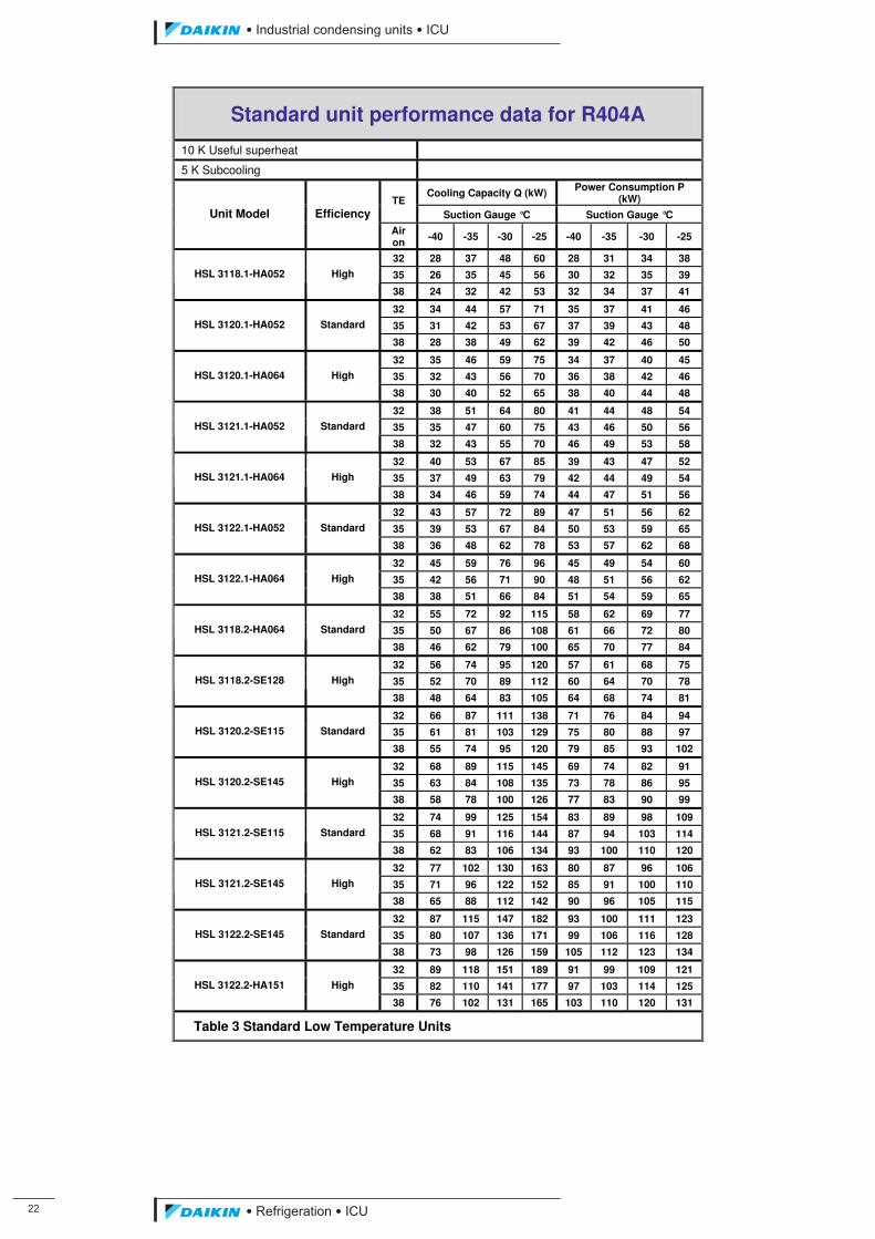
• Standard unit performance data for R404A (low temperature units).
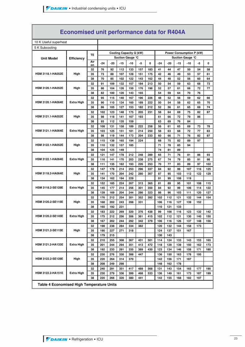
• Economised unit performance data for R404A (high temperature units).
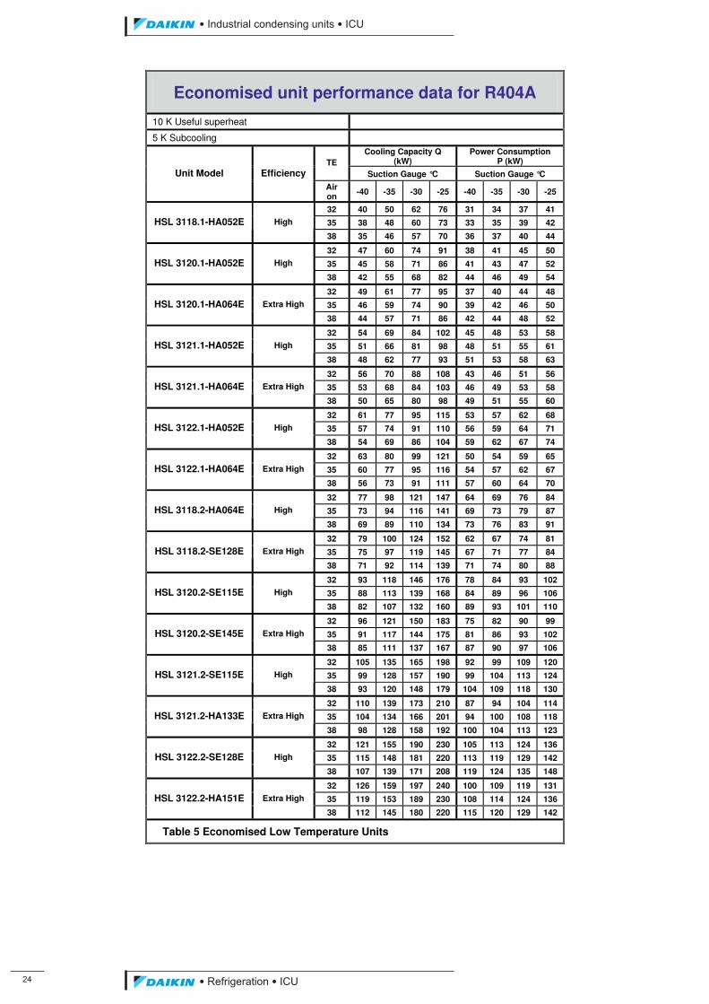
• Economised unit performance data for R404A (low temperature units).
• Technical specification for R404A.
• Dimensions and weight
ICU.pdf 27 26/01/2011 11:11:44
�
��������� ����������������������
������������������
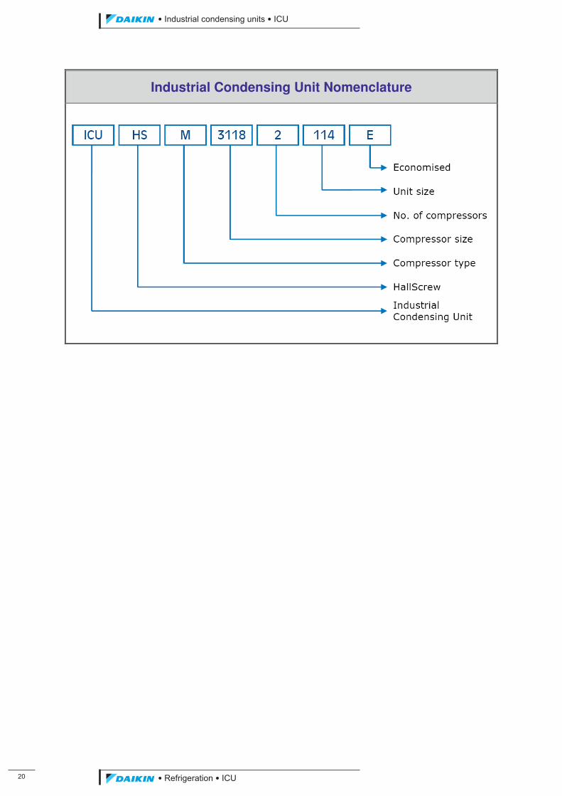
Industrial Condensing Unit Nomenclature
ICU.pdf 28 26/01/2011 11:11:44
��������� ����������������������
������������������ ��
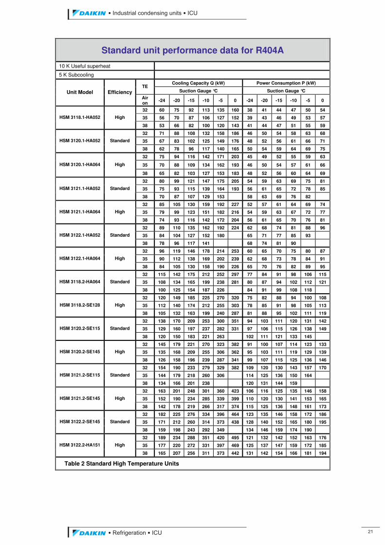
Standard unit performance data for R404A
10 K Useful superheat
5 K Subcooling
Cooling Capacity Q (kW) Power Consumption P (kW) TE
Suction Gauge °C Suction Gauge °C Unit Model Efficiency Air on -24 -20 -15 -10 -5 0 -24 -20 -15 -10 -5 0
32 60 75 92 113 135 160 38 41 44 47 50 54
35 56 70 87 106 127 152 39 43 46 49 53 57 HSM 3118.1-HA052 High
38 53 66 82 100 120 143 41 44 47 51 55 59
32 71 88 108 132 158 186 46 50 54 58 63 68
35 67 83 102 125 149 176 48 52 56 61 66 71 HSM 3120.1-HA052 Standard
38 62 78 96 117 140 165 50 54 59 64 69 75
32 75 94 116 142 171 203 45 49 52 55 59 63
35 70 88 109 134 162 193 46 50 54 57 61 66 HSM 3120.1-HA064 High
38 65 82 103 127 153 183 48 52 56 60 64 69
32 80 99 121 147 175 205 54 59 63 69 75 81
35 75 93 115 139 164 193 56 61 65 72 78 85 HSM 3121.1-HA052 Standard
38 70 87 107 129 153 58 63 69 76 82
32 85 105 130 159 192 227 52 57 61 64 69 74
35 79 99 123 151 182 216 54 59 63 67 72 77 HSM 3121.1-HA064 High
38 74 93 116 142 172 204 56 61 65 70 76 81
32 89 110 135 162 192 224 62 68 74 81 88 96
35 84 104 127 152 180 65 71 77 85 93 HSM 3122.1-HA052 Standard
38 78 96 117 141 68 74 81 90
32 96 119 146 178 214 253 60 65 70 75 80 87
35 90 112 138 169 202 239 62 68 73 78 84 91 HSM 3122.1-HA064 High
38 84 105 130 158 190 226 65 70 76 82 89 95
32 115 142 175 212 252 297 77 84 91 98 106 115
35 108 134 165 199 238 281 80 87 94 102 112 121 HSM 3118.2-HA064 Standard
38 100 125 154 187 226 84 91 99 108 118
32 120 149 185 225 270 320 75 82 88 94 100 108
35 112 140 174 212 255 303 78 85 91 98 105 113 HSM 3118.2-SE128 High
38 105 132 163 199 240 287 81 88 95 102 111 119
32 138 170 209 253 300 351 94 103 111 120 131 142
35 129 160 197 237 282 331 97 106 115 126 138 149 HSM 3120.2-SE115 Standard
38 120 150 183 221 263 102 111 121 133 145
32 145 179 221 270 323 382 91 100 107 114 123 133
35 135 168 209 255 306 362 95 103 111 119 129 139 HSM 3120.2-SE145 High
38 126 158 196 239 287 341 99 107 115 125 136 146
32 154 190 233 279 329 382 109 120 130 143 157 170
35 144 179 218 260 306 114 125 136 150 164 HSM 3121.2-SE115 Standard
38 134 166 201 238 120 131 144 159
32 163 201 248 301 360 423 106 116 125 135 146 158
35 152 190 234 285 339 399 110 120 130 141 153 165 HSM 3121.2-SE145 High
38 142 178 219 266 317 374 115 125 136 148 161 173
32 182 225 276 334 396 464 123 135 146 158 172 186
35 171 212 260 314 373 438 128 140 152 165 180 195 HSM 3122.2-SE145 Standard
38 159 198 243 292 349 134 146 159 174 190
32 189 234 288 351 420 495 121 132 142 152 163 176
35 177 220 272 331 397 469 125 137 147 159 172 185 HSM 3122.2-HA151 High
38 165 207 256 311 373 442 131 142 154 166 181 194
Table 2 Standard High Temperature Units
ICU.pdf 29 26/01/2011 11:11:44
��
��������� ����������������������
������������������
Standard unit performance data for R404A
10 K Useful superheat
5 K Subcooling
Cooling Capacity Q (kW) Power Consumption P (kW) TE
Suction Gauge °C Suction Gauge °C Unit Model Efficiency Air on -40 -35 -30 -25 -40 -35 -30 -25
32 28 37 48 60 28 31 34 38
35 26 35 45 56 30 32 35 39 HSL 3118.1-HA052 High
38 24 32 42 53 32 34 37 41
32 34 44 57 71 35 37 41 46
35 31 42 53 67 37 39 43 48 HSL 3120.1-HA052 Standard
38 28 38 49 62 39 42 46 50
32 35 46 59 75 34 37 40 45
35 32 43 56 70 36 38 42 46 HSL 3120.1-HA064 High
38 30 40 52 65 38 40 44 48
32 38 51 64 80 41 44 48 54
35 35 47 60 75 43 46 50 56 HSL 3121.1-HA052 Standard
38 32 43 55 70 46 49 53 58
32 40 53 67 85 39 43 47 52
35 37 49 63 79 42 44 49 54 HSL 3121.1-HA064 High
38 34 46 59 74 44 47 51 56
32 43 57 72 89 47 51 56 62
35 39 53 67 84 50 53 59 65 HSL 3122.1-HA052 Standard
38 36 48 62 78 53 57 62 68
32 45 59 76 96 45 49 54 60
35 42 56 71 90 48 51 56 62 HSL 3122.1-HA064 High
38 38 51 66 84 51 54 59 65
32 55 72 92 115 58 62 69 77
35 50 67 86 108 61 66 72 80 HSL 3118.2-HA064 Standard
38 46 62 79 100 65 70 77 84
32 56 74 95 120 57 61 68 75
35 52 70 89 112 60 64 70 78 HSL 3118.2-SE128 High
38 48 64 83 105 64 68 74 81
32 66 87 111 138 71 76 84 94
35 61 81 103 129 75 80 88 97 HSL 3120.2-SE115 Standard
38 55 74 95 120 79 85 93 102
32 68 89 115 145 69 74 82 91
35 63 84 108 135 73 78 86 95 HSL 3120.2-SE145 High
38 58 78 100 126 77 83 90 99
32 74 99 125 154 83 89 98 109
35 68 91 116 144 87 94 103 114 HSL 3121.2-SE115 Standard
38 62 83 106 134 93 100 110 120
32 77 102 130 163 80 87 96 106
35 71 96 122 152 85 91 100 110 HSL 3121.2-SE145 High
38 65 88 112 142 90 96 105 115
32 87 115 147 182 93 100 111 123
35 80 107 136 171 99 106 116 128 HSL 3122.2-SE145 Standard
38 73 98 126 159 105 112 123 134
32 89 118 151 189 91 99 109 121
35 82 110 141 177 97 103 114 125 HSL 3122.2-HA151 High
38 76 102 131 165 103 110 120 131
Table 3 Standard Low Temperature Units
ICU.pdf 30 26/01/2011 11:11:44
��������� ����������������������
������������������ ��
Economised unit performance data for R404A
10 K Useful superheat 5 K Subcooling
Cooling Capacity Q (kW) Power Consumption P (kW) TE
Suction Gauge °C Suction Gauge °C Unit Model Efficiency Air on -24 -20 -15 -10 -5 0 -24 -20 -15 -10 -5 0
32 76 92 112 133 157 183 41 44 47 50 54 58
35 73 88 107 128 151 175 42 46 49 53 57 61 HSM 3118.1-HA052E High
38 70 85 102 122 143 162 44 48 52 56 60 64
32 91 109 132 157 184 213 50 54 59 63 68 73
35 86 104 126 150 176 198 52 57 61 66 72 77 HSM 3120.1-HA052E High
38 82 100 120 143 165 54 59 64 70 76
32 95 115 140 167 196 226 48 52 56 59 62 66
35 90 110 134 160 189 222 50 54 58 62 65 70 HSM 3120.1-HA064E Extra High
38 86 105 127 153 182 212 52 56 61 65 69 74
32 102 123 148 175 205 231 58 64 69 75 82 87
35 98 118 141 167 193 61 66 72 79 86 HSM 3121.1-HA052E High
38 93 112 135 159 63 69 76 84
32 108 131 158 189 222 258 56 61 65 69 73 78
35 103 125 151 181 214 250 58 63 68 72 77 83 HSM 3121.1-HA064E Extra High
38 98 119 144 173 204 233 60 66 71 76 82 87
32 115 138 165 194 224 68 75 82 89 97
35 110 132 157 185 71 78 85 94 HSM 3122.1-HA052E High
38 104 125 149 74 81 89
32 121 147 178 212 248 289 65 71 76 81 86 93
35 116 141 170 203 238 275 67 74 79 85 91 98 HSM 3122.1-HA064E Extra High
38 111 135 162 193 226 253 70 77 83 89 97 102
32 147 178 214 253 296 337 84 92 99 107 116 125
35 141 170 204 242 280 307 87 95 103 112 122 129 HSM 3118.2-HA064E High
38 134 162 194 229 91 99 108 119
32 152 185 224 267 313 365 81 89 95 101 108 115
35 145 177 214 256 301 350 84 92 99 106 114 122 HSM 3118.2-SE128E Extra High
38 139 169 204 244 286 323 88 96 103 111 120 127
32 176 212 254 301 352 392 102 112 121 132 144 154
35 168 202 243 288 331 106 116 127 139 152 HSM 3120.2-SE115E High
38 160 192 231 110 121 133
32 183 222 269 320 376 438 99 108 116 123 132 142
35 175 212 256 306 361 415 102 112 121 130 140 150 HSM 3120.2-SE145E Extra High
38 167 202 244 292 342 379 106 116 126 137 148 156
32 198 238 284 334 382 120 132 144 158 173
35 190 227 271 318 124 137 151 167 HSM 3121.2-SE115E High
38 179 215 130 143
32 210 255 308 367 431 501 114 124 133 143 153 165
35 201 244 294 351 413 472 118 129 139 150 162 173 HSM 3121.2-HA133E Extra High
38 192 233 281 335 389 430 123 134 146 158 171 180
32 230 276 330 388 447 136 150 163 178 195
35 220 264 314 370 142 156 171 187 HSM 3122.2-SE128E High
38 208 249 298 148 162 178
32 240 291 351 417 489 568 131 143 154 165 177 190
35 230 279 336 399 468 533 136 149 161 173 187 199 HSM 3122.2-HA151E Extra High
38 220 266 320 380 441 142 155 168 182 197
Table 4 Economised High Temperature Units
ICU.pdf 31 26/01/2011 11:11:44
��
��������� ����������������������
������������������
Economised unit performance data for R404A
10 K Useful superheat
5 K Subcooling
Cooling Capacity Q (kW)
Power Consumption P (kW) TE
Suction Gauge °C Suction Gauge °C Unit Model Efficiency Air on -40 -35 -30 -25 -40 -35 -30 -25
32 40 50 62 76 31 34 37 41
35 38 48 60 73 33 35 39 42 HSL 3118.1-HA052E High
38 35 46 57 70 36 37 40 44
32 47 60 74 91 38 41 45 50
35 45 58 71 86 41 43 47 52 HSL 3120.1-HA052E High
38 42 55 68 82 44 46 49 54
32 49 61 77 95 37 40 44 48
35 46 59 74 90 39 42 46 50 HSL 3120.1-HA064E Extra High
38 44 57 71 86 42 44 48 52
32 54 69 84 102 45 48 53 58
35 51 66 81 98 48 51 55 61 HSL 3121.1-HA052E High
38 48 62 77 93 51 53 58 63
32 56 70 88 108 43 46 51 56
35 53 68 84 103 46 49 53 58 HSL 3121.1-HA064E Extra High
38 50 65 80 98 49 51 55 60
32 61 77 95 115 53 57 62 68
35 57 74 91 110 56 59 64 71 HSL 3122.1-HA052E High
38 54 69 86 104 59 62 67 74
32 63 80 99 121 50 54 59 65
35 60 77 95 116 54 57 62 67 HSL 3122.1-HA064E Extra High
38 56 73 91 111 57 60 64 70
32 77 98 121 147 64 69 76 84
35 73 94 116 141 69 73 79 87 HSL 3118.2-HA064E High
38 69 89 110 134 73 76 83 91
32 79 100 124 152 62 67 74 81
35 75 97 119 145 67 71 77 84 HSL 3118.2-SE128E Extra High
38 71 92 114 139 71 74 80 88
32 93 118 146 176 78 84 93 102
35 88 113 139 168 84 89 96 106 HSL 3120.2-SE115E High
38 82 107 132 160 89 93 101 110
32 96 121 150 183 75 82 90 99
35 91 117 144 175 81 86 93 102 HSL 3120.2-SE145E Extra High
38 85 111 137 167 87 90 97 106
32 105 135 165 198 92 99 109 120
35 99 128 157 190 99 104 113 124 HSL 3121.2-SE115E High
38 93 120 148 179 104 109 118 130
32 110 139 173 210 87 94 104 114
35 104 134 166 201 94 100 108 118 HSL 3121.2-HA133E Extra High
38 98 128 158 192 100 104 113 123
32 121 155 190 230 105 113 124 136
35 115 148 181 220 113 119 129 142 HSL 3122.2-SE128E High
38 107 139 171 208 119 124 135 148
32 126 159 197 240 100 109 119 131
35 119 153 189 230 108 114 124 136 HSL 3122.2-HA151E Extra High
38 112 145 180 220 115 120 129 142
Table 5 Economised Low Temperature Units
ICU.pdf 32 26/01/2011 11:11:44
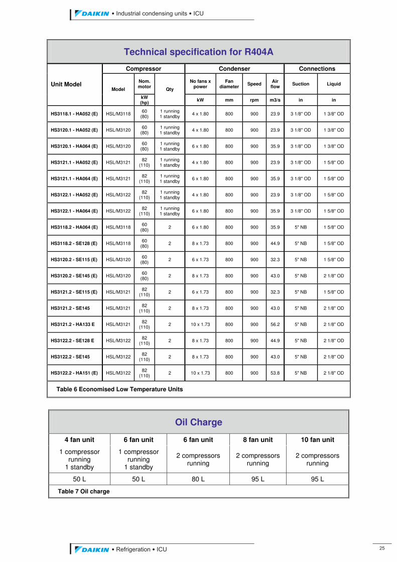
��������� ����������������������
������������������ ��
Technical specification for R404A
Compressor Condenser Connections
Nom. motor
No fans x power
Fan diameter Speed Air
flow Suction Liquid Unit Model Model
kW (hp)
Qty
kW mm rpm m3/s in in
HS3118.1 - HA052 (E) HSL/M3118 60 (80)
1 running 1 standby 4 x 1.80 800 900 23.9 3 1/8" OD 1 3/8" OD
HS3120.1 - HA052 (E) HSL/M3120 60 (80)
1 running 1 standby
4 x 1.80 800 900 23.9 3 1/8" OD 1 3/8" OD
HS3120.1 - HA064 (E) HSL/M3120 60 (80)
1 running 1 standby 6 x 1.80 800 900 35.9 3 1/8" OD 1 3/8" OD
HS3121.1 - HA052 (E) HSL/M3121 82 (110)
1 running 1 standby 4 x 1.80 800 900 23.9 3 1/8" OD 1 5/8" OD
HS3121.1 - HA064 (E) HSL/M3121 82 (110)
1 running 1 standby
6 x 1.80 800 900 35.9 3 1/8" OD 1 5/8" OD
HS3122.1 - HA052 (E) HSL/M3122 82 (110)
1 running 1 standby 4 x 1.80 800 900 23.9 3 1/8" OD 1 5/8" OD
HS3122.1 - HA064 (E) HSL/M3122 82 (110)
1 running 1 standby 6 x 1.80 800 900 35.9 3 1/8" OD 1 5/8" OD
HS3118.2 - HA064 (E) HSL/M3118 60 (80)
2 6 x 1.80 800 900 35.9 5" NB 1 5/8" OD
HS3118.2 - SE128 (E) HSL/M3118 60 (80) 2 8 x 1.73 800 900 44.9 5" NB 1 5/8" OD
HS3120.2 - SE115 (E) HSL/M3120 60 (80) 2 6 x 1.73 800 900 32.3 5" NB 1 5/8" OD
HS3120.2 - SE145 (E) HSL/M3120 60 (80)
2 8 x 1.73 800 900 43.0 5" NB 2 1/8" OD
HS3121.2 - SE115 (E) HSL/M3121 82 (110) 2 6 x 1.73 800 900 32.3 5" NB 1 5/8" OD
HS3121.2 - SE145 HSL/M3121 82 (110) 2 8 x 1.73 800 900 43.0 5" NB 2 1/8" OD
HS3121.2 - HA133 E HSL/M3121 82 (110)
2 10 x 1.73 800 900 56.2 5" NB 2 1/8" OD
HS3122.2 - SE128 E HSL/M3122 82 (110) 2 8 x 1.73 800 900 44.9 5" NB 2 1/8" OD
HS3122.2 - SE145 HSL/M3122 82 (110) 2 8 x 1.73 800 900 43.0 5" NB 2 1/8" OD
HS3122.2 - HA151 (E) HSL/M3122 82 (110)
2 10 x 1.73 800 900 53.8 5" NB 2 1/8" OD
Table 6 Economised Low Temperature Units
Oil Charge
4 fan unit 6 fan unit 6 fan unit 8 fan unit 10 fan unit
1 compressor running
1 standby
1 compressor running
1 standby
2 compressors running
2 compressors running
2 compressors running
50 L 50 L 80 L 95 L 95 L
Table 7 Oil charge
ICU.pdf 33 26/01/2011 11:11:44
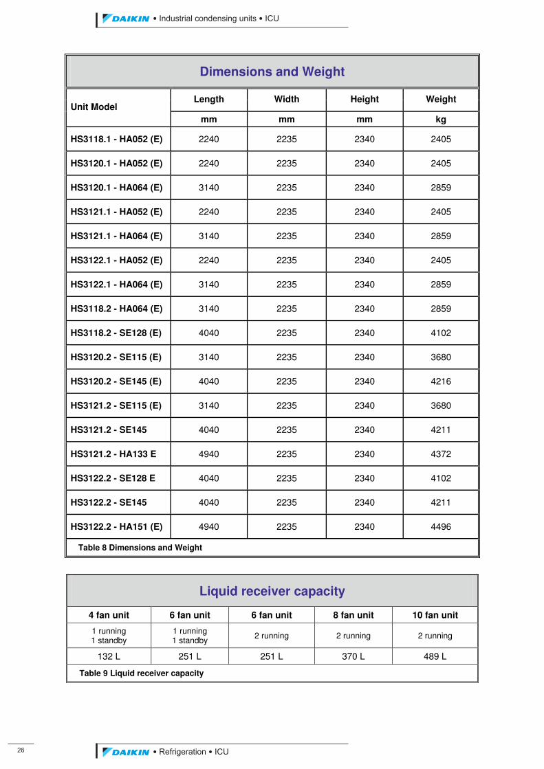
��
��������� ����������������������
������������������
Dimensions and Weight
Length Width Height Weight Unit Model
mm mm mm kg
HS3118.1 - HA052 (E) 2240 2235 2340 2405
HS3120.1 - HA052 (E) 2240 2235 2340 2405
HS3120.1 - HA064 (E) 3140 2235 2340 2859
HS3121.1 - HA052 (E) 2240 2235 2340 2405
HS3121.1 - HA064 (E) 3140 2235 2340 2859
HS3122.1 - HA052 (E) 2240 2235 2340 2405
HS3122.1 - HA064 (E) 3140 2235 2340 2859
HS3118.2 - HA064 (E) 3140 2235 2340 2859
HS3118.2 - SE128 (E) 4040 2235 2340 4102
HS3120.2 - SE115 (E) 3140 2235 2340 3680
HS3120.2 - SE145 (E) 4040 2235 2340 4216
HS3121.2 - SE115 (E) 3140 2235 2340 3680
HS3121.2 - SE145 4040 2235 2340 4211
HS3121.2 - HA133 E 4940 2235 2340 4372
HS3122.2 - SE128 E 4040 2235 2340 4102
HS3122.2 - SE145 4040 2235 2340 4211
HS3122.2 - HA151 (E) 4940 2235 2340 4496
Table 8 Dimensions and Weight
Liquid receiver capacity
4 fan unit 6 fan unit 6 fan unit 8 fan unit 10 fan unit
1 running 1 standby
1 running 1 standby 2 running 2 running 2 running
132 L 251 L 251 L 370 L 489 L
Table 9 Liquid receiver capacity
ICU.pdf 34 26/01/2011 11:11:44
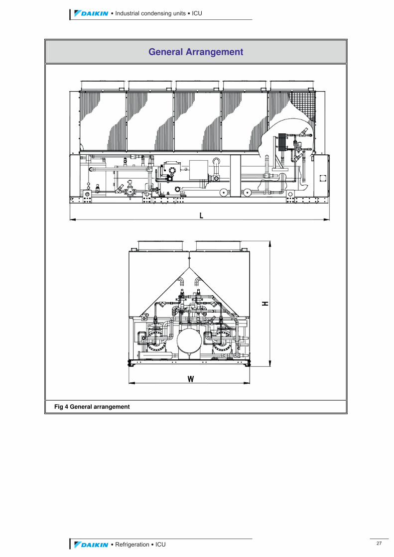
��������� ����������������������
������������������ ��
General Arrangement
Fig 4 General arrangement
ICU.pdf 35 26/01/2011 11:11:44

��
��������� ����������������������
������������������
Appendix 2 System Schematic Flow Diagram
• Flow and instrumentation diagram.
• Flow and instrumentation diagram of the economiser option.
• Flow and instrumentation diagram of the liquid injection option.
ICU.pdf 36 26/01/2011 11:11:44
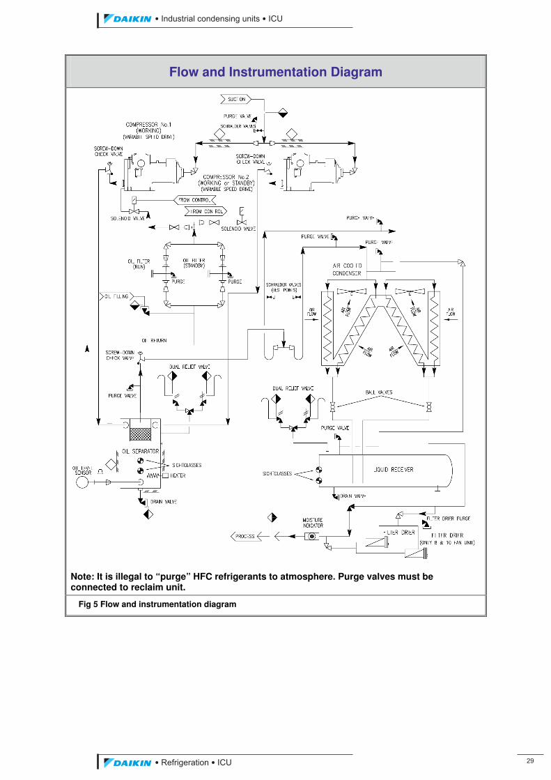
��������� ����������������������
������������������ ��
Flow and Instrumentation Diagram
Note: It is illegal to “purge” HFC refrigerants to atmosphere. Purge valves must be connected to reclaim unit.
Fig 5 Flow and instrumentation diagram
ICU.pdf 37 26/01/2011 11:11:44
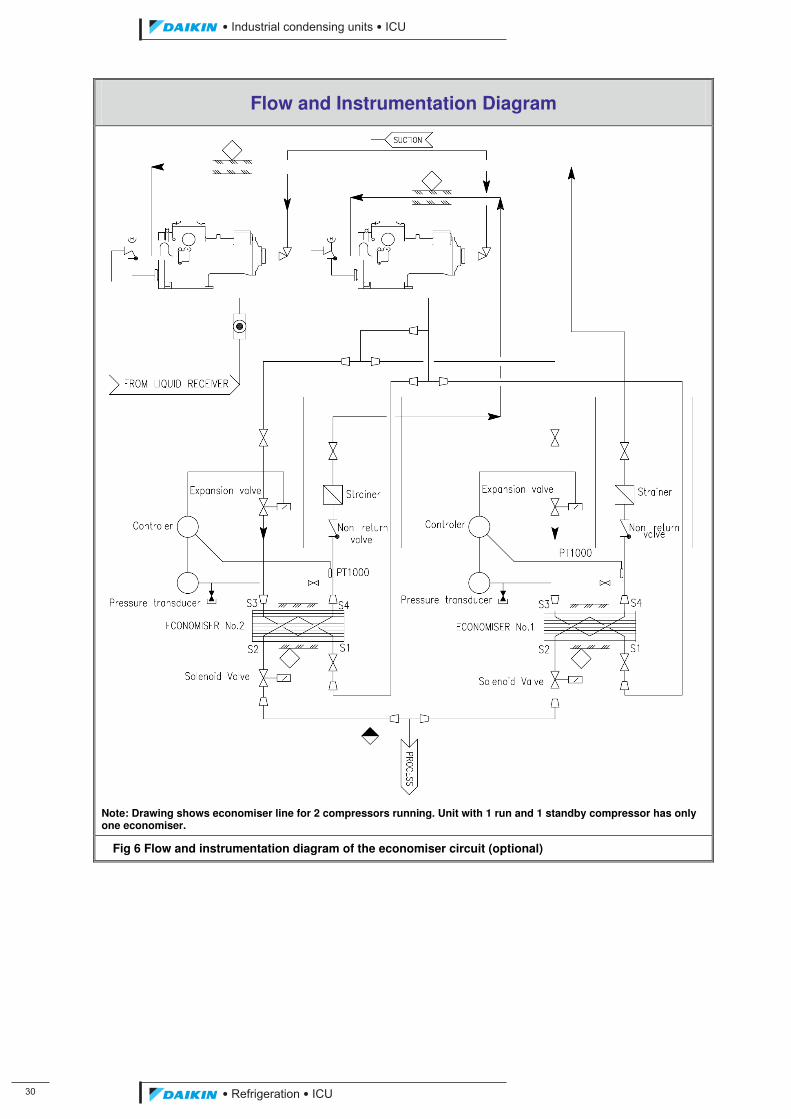
�
��������� ����������������������
������������������
Flow and Instrumentation Diagram
Note: Drawing shows economiser line for 2 compressors running. Unit with 1 run and 1 standby compressor has only one economiser.
Fig 6 Flow and instrumentation diagram of the economiser circuit (optional)
ICU.pdf 38 26/01/2011 11:11:45
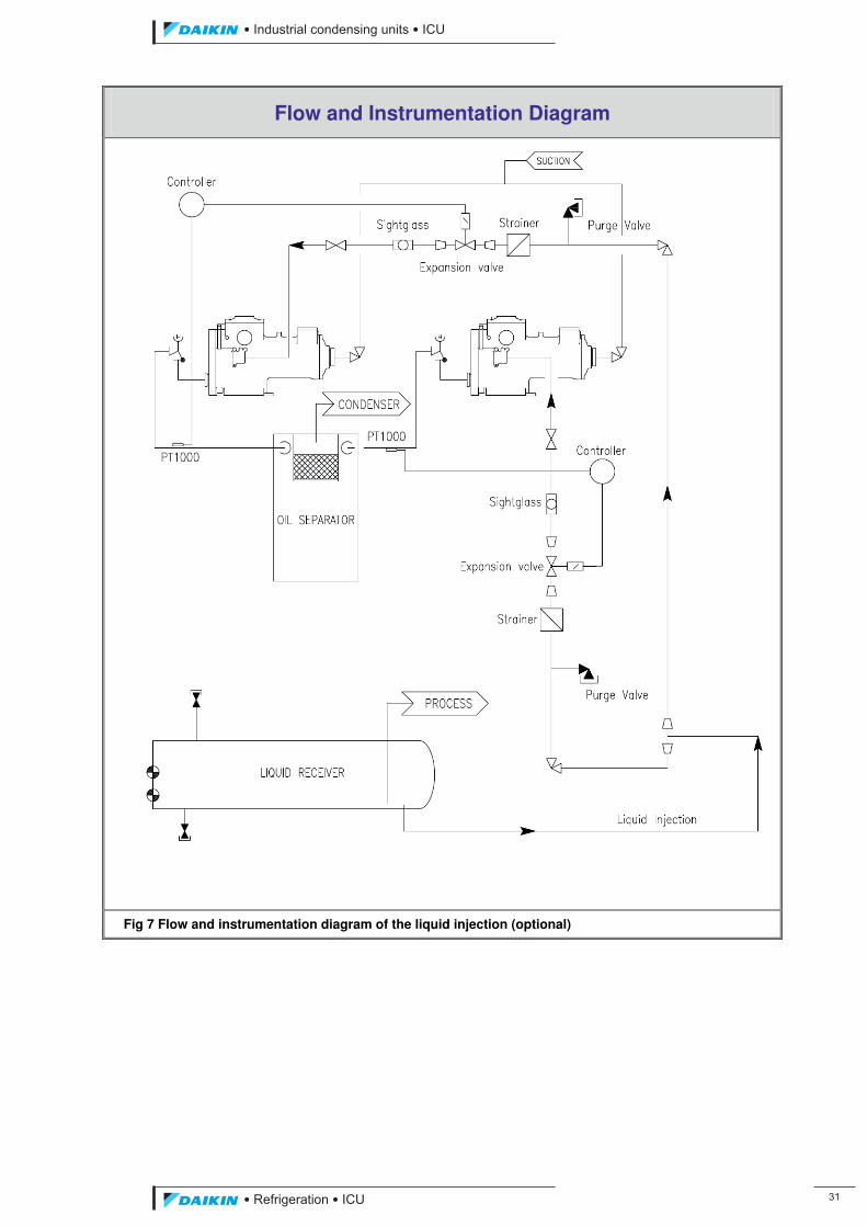
��������� ����������������������
������������������ ��
Flow and Instrumentation Diagram
Fig 7 Flow and instrumentation diagram of the liquid injection (optional)
ICU.pdf 39 26/01/2011 11:11:45
��
��������� ����������������������
������������������
Appendix 3 ICU Performance Data
For detailed selection use the J & E Hall International HallScrew compressor selection software, available on CD.
Continuous research and development may necessitate changes to specifications and data in this Application Manual and the J & E Hall International Compressor Selection Software.
Subcooling & Superheat Correction Factors
The performance data is based on 10.0 oC suction superheat and 5.0 oC liquid subcooling.
The suction superheat is assumed to be usefully obtained. Such superheat can be obtained in the evaporator or in a liquid to suction heat exchanger or similar vessel in the refrigeration circuit producing a beneficial effect.
The approximate effect of an increase in useful suction superheat is an increase in capacity of 0.17 % for every additional 1.0 oC superheat.
Non usefully obtained superheat (such that might be picked up in the suction line due to heat exchange with the environment) will have a detrimental effect on performance.
The approximate effect is a loss in performance of approximately 0.7 % for each additional 1.0 oC of non useful suction superheat.
It is important to ensure adequate suction superheat. Insufficient superheat can result in liquid carry over into the compressor, reducing performance and also resulting in inadequate discharge superheat for satisfactory oil separation.
Additional subcooling will have a beneficial effect on the system performance.
The approximate effect of an increase in liquid subcooling is an increase in capacity of 1.1 % for every additional 1.0 oC subcooling.
If the useful superheat is obtained in a suction to liquid heat exchanger then only the effect of the increase in suction superheat should be taken in to account. Otherwise the effect on performance will be added twice. Using the increase in suction superheat also includes the effect of the change in specific volume at the compressor suction.
ICU.pdf 40 26/01/2011 11:11:45
��������� ����������������������
������������������ ��
CAUTION
Static sensitive components. A static discharge while handling electronic circuit boards can cause damage to the components. Discharge any static electrical charge by touching the bare metal inside the control panel before performing any service work. Never unplug any cables, circuit board terminal blocks, or power plugs while power is applied to the panel.
WARNING
Electric shock hazard. It can cause personal injury or equipment damage. This equipment must be properly grounded. Connections and service of the MTCU control panel must be performed only by personnel that are knowledgeable in the operation of the equipment being controlled.
ICU.pdf 41 26/01/2011 11:11:45
��
��������� ����������������������
������������������
1. Introduction
This manual provides installation, setup, troubleshooting and other general information for MTCU software. It is intended for J&EHall personnel; its distribution to third operators should require some review.
MTCU software is able to manage up to two J&E Hall single-screw compressors using a single pCO2 board.
The control panel provides all monitoring and control functions required for the safe and efficient operation of the compressor. The operator can monitor all operating conditions and set operating parameters using the system display.
MTCU software monitors all safety devices on the compressor and will take corrective action if the compressor is operating out of it’s normal design conditions. If a fault condition arises, the controller will shut the system down and activate an alarm output. Important operating conditions at the time an alarm occurs are retained in the controller’s memory to aid in troubleshooting and fault analysis.
MTCU software panel may communicate with external system using a Carel proprietary protocol or LonWork, Backnet or Modbus protocol.
ICU.pdf 42 26/01/2011 11:11:45
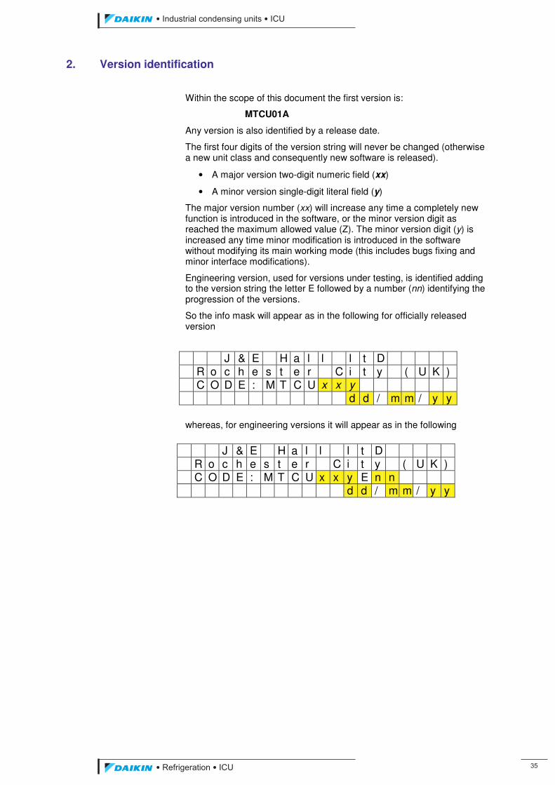
��������� ����������������������
������������������ ��
2. Version identification
Within the scope of this document the first version is:
MTCU01A
Any version is also identified by a release date.
The first four digits of the version string will never be changed (otherwise a new unit class and consequently new software is released).
• A major version two-digit numeric field (xx)
• A minor version single-digit literal field (y)
The major version number (xx) will increase any time a completely new function is introduced in the software, or the minor version digit as reached the maximum allowed value (Z). The minor version digit (y) is increased any time minor modification is introduced in the software without modifying its main working mode (this includes bugs fixing and minor interface modifications).
Engineering version, used for versions under testing, is identified adding to the version string the letter E followed by a number (nn) identifying the progression of the versions.
So the info mask will appear as in the following for officially released version
whereas, for engineering versions it will appear as in the following
J & E H a l l l t D R o c h e s t e r C i t y ( U K ) C O D E : M T C U x x y E n n d d / m m / y y
J & E H a l l l t D R o c h e s t e r C i t y ( U K ) C O D E : M T C U x x y d d / m m / y y
ICU.pdf 43 26/01/2011 11:11:45
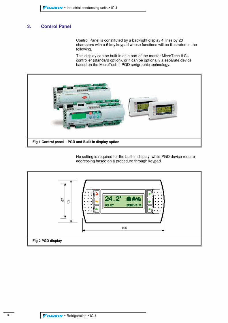
��
��������� ����������������������
������������������
3. Control Panel
Control Panel is constituted by a backlight display 4 lines by 20 characters with a 6 key keypad whose functions will be illustrated in the following.
This display can be built-in as a part of the master MicroTech II C+ controller (standard option), or it can be optionally a separate device based on the MicroTech II PGD serigraphic technology.
���
Fig 1 Control panel – PGD and Built-in display option
�
No setting is required for the built in display, while PGD device require addressing based on a procedure through keypad.
Fig 2 PGD display
ICU.pdf 44 26/01/2011 11:11:45
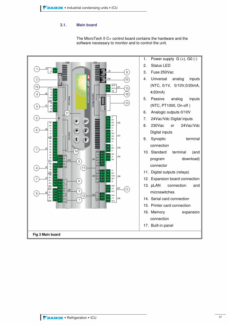
��������� ����������������������
������������������ ��
3.1. Main board
The MicroTech II C+ control board contains the hardware and the software necessary to monitor and to control the unit.
1. Power supply G (+), G0 (-)
2. Status LED
3. Fuse 250Vac
4. Universal analog inputs
(NTC, 0/1V, 0/10V,0/20mA,
4/20mA)
5. Passive analog inputs
(NTC, PT1000, On-off )
6. Analogic outputs 0/10V
7. 24Vac/Vdc Digital inputs
8. 230Vac or 24Vac/Vdc
Digital inputs
9. Synoptic terminal
connection
10. Standard terminal (and
program download)
connector
11. Digital outputs (relays)
12. Expansion board connection
13. pLAN connection and
microswitches
14. Serial card connection
15. Printer card connection
16. Memory expansion
connection
17. Built-in panel
Fig 3 Main board
ICU.pdf 45 26/01/2011 11:11:45
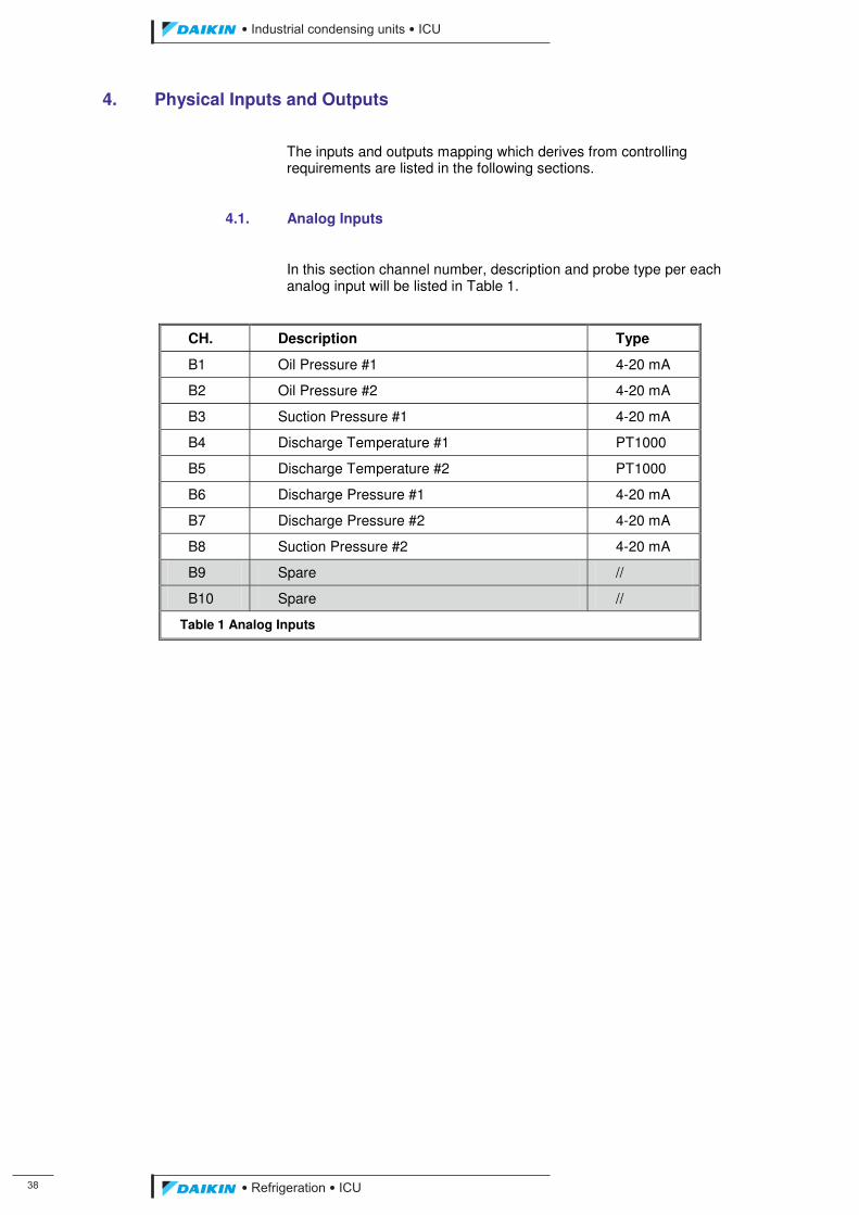
��
��������� ����������������������
������������������
4. Physical Inputs and Outputs
The inputs and outputs mapping which derives from controlling requirements are listed in the following sections.
4.1. Analog Inputs
In this section channel number, description and probe type per each analog input will be listed in Table 1.
CH. Description Type
B1 Oil Pressure #1 4-20 mA
B2 Oil Pressure #2 4-20 mA
B3 Suction Pressure #1 4-20 mA
B4 Discharge Temperature #1 PT1000
B5 Discharge Temperature #2 PT1000
B6 Discharge Pressure #1 4-20 mA
B7 Discharge Pressure #2 4-20 mA
B8 Suction Pressure #2 4-20 mA
B9 Spare //
B10 Spare //
Table 1 Analog Inputs
ICU.pdf 46 26/01/2011 11:11:45
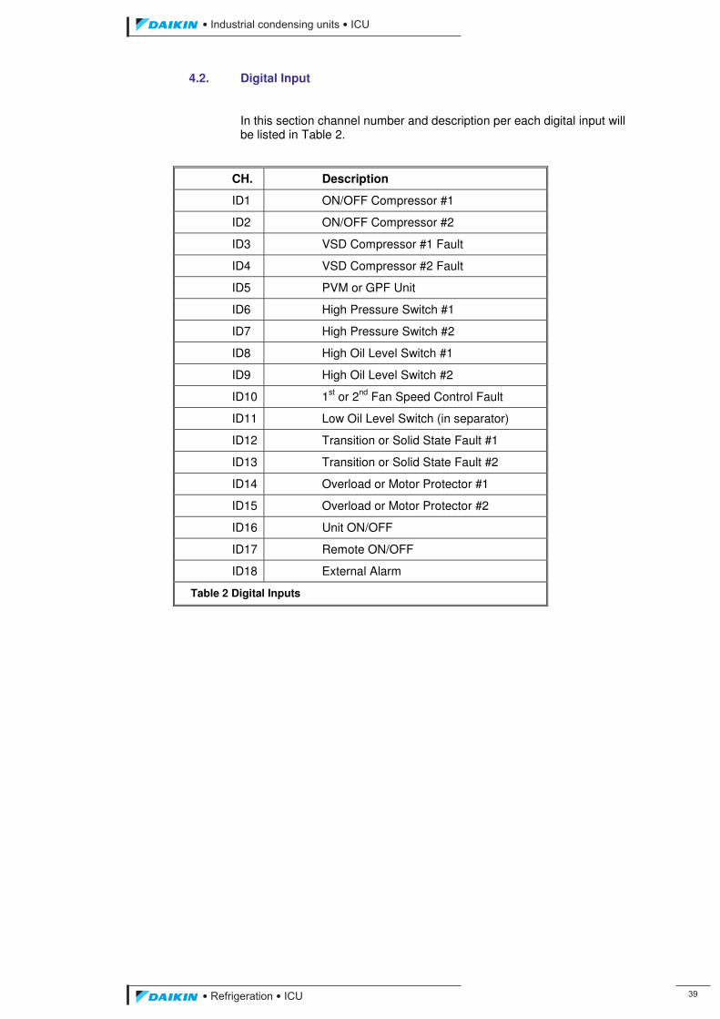
��������� ����������������������
������������������ ��
4.2. Digital Input
In this section channel number and description per each digital input will be listed in Table 2.
CH. Description
ID1 ON/OFF Compressor #1
ID2 ON/OFF Compressor #2
ID3 VSD Compressor #1 Fault
ID4 VSD Compressor #2 Fault
ID5 PVM or GPF Unit
ID6 High Pressure Switch #1
ID7 High Pressure Switch #2
ID8 High Oil Level Switch #1
ID9 High Oil Level Switch #2
ID10 1st or 2nd Fan Speed Control Fault
ID11 Low Oil Level Switch (in separator)
ID12 Transition or Solid State Fault #1
ID13 Transition or Solid State Fault #2
ID14 Overload or Motor Protector #1
ID15 Overload or Motor Protector #2
ID16 Unit ON/OFF
ID17 Remote ON/OFF
ID18 External Alarm
Table 2 Digital Inputs
ICU.pdf 47 26/01/2011 11:11:45
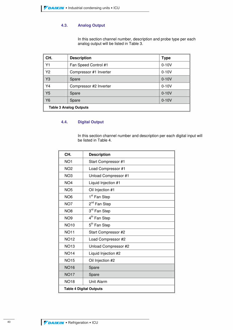
�
��������� ����������������������
������������������
4.3. Analog Output
In this section channel number, description and probe type per each analog output will be listed in Table 3.
CH. Description Type
Y1 Fan Speed Control #1 0-10V
Y2 Compressor #1 Inverter 0-10V
Y3 Spare 0-10V
Y4 Compressor #2 Inverter 0-10V
Y5 Spare 0-10V
Y6 Spare 0-10V
Table 3 Analog Outputs
4.4. Digital Output
In this section channel number and description per each digital input will be listed in Table 4.
CH. Description
NO1 Start Compressor #1
NO2 Load Compressor #1
NO3 Unload Compressor #1
NO4 Liquid Injection #1
NO5 Oil Injection #1
NO6 1st Fan Step
NO7 2nd Fan Step
NO8 3rd Fan Step
NO9 4th Fan Step
NO10 5th Fan Step
NO11 Start Compressor #2
NO12 Load Compressor #2
NO13 Unload Compressor #2
NO14 Liquid Injection #2
NO15 Oil Injection #2
NO16 Spare
NO17 Spare
NO18 Unit Alarm
Table 4 Digital Outputs
ICU.pdf 48 26/01/2011 11:11:45
��������� ����������������������
������������������ ��
5. Main Control Features
In the following the main features of the control system will be described.
5.1. Controller Purpose
The system is intended to control Suction Pressure trying to keep it at a user selected setpoint.
The system operates to optimize components performances from both efficiency and duration point of view.
The system assures a safe operation of the unit and all components. Many different precautions are operated to prevent dangerous situations.
5.2. Unit Enabling
The system implements different modes to Enable/Disable Unit. These modes are the following:
• Keypad: a key on the keypad is used to enable the Unit at its first start-up and in case of power loss.
• Local Switch: when the digital input “Unit ON/OFF” is opened the unit will be in the “OFF Local Switch” Status; when the digital input closes the Unit could be ON or “OFF Remote Switch” depending on the status of the digital input “Remote ON/OFF”.
• Remote Switch: when the local switch is ON if the “Remote ON/OFF” digital input is closed the Unit will be ON, whereas if the “Remote ON/OFF” digital input is opened the Unit will be “OFF Remote Switch”.
• Time Schedule: a timetable allows users to program “OFF Time Schedule” on a week base; it will be possible to set also holydays in which Unit will be “OFF Time Schedule”.
• Network: it is possible to set the code to respond to BAS or Remote Monitoring Systems ON/OFF signals through a serial line connection which sets the Unit in the “Rem. Comm. OFF” status.
To be ON all the previous conditions must be met.
5.3. Setpoint Management
The control is able to manage the Suction Pressure setpoint set in user interface using the keypad.
BAS or Remote Monitoring Systems could also modify the Suction Pressure setpoint through a serial line connection.
ICU.pdf 49 26/01/2011 11:11:45
��
��������� ����������������������
������������������
5.4. Compressors Capacity Control
Two types of capacity control are implemented:
• Automatic: the compressor start/stop and its capacity is automatically managed by the software to allow setpoint respect.
• Manual: the compressor is started by the operator and its capacity is managed by the operator acting on the system terminal. In this case the compressor will not be used by the software to allow setpoint respect.
• Compressors in Manual Mode are automatically switched in Automatic Mode in different cases:
• Shut-Down: when a compressor is switched OFF it is put back in Automatic control.
• Limitations: if a limitation takes place the compressor is put back in Automatic control.
• Safeties: if a safety condition takes place the compressor is put back in Automatic control.
5.4.1. Automatic Control
A specialized PID algorithm is used to determine the magnitude of corrective action on capacity control solenoid.
The compressor loading or unloading is obtained keeping the loading or unloading solenoid energized for a fixed time (pulse duration), while a time interval between two subsequent pulses is evaluated by a PD controller.
If the output of the PD algorithm doesn’t change, the time interval between pulses is constant; this is the integral effect of the controller, at a constant error the action is repeated at constant intervals (with the additional feature of a variable integral time).
It’s required to define the proportional band and the derivative time of the PD control, together with the pulse duration and minimum and maximum intervals between pulses where the minimum interval is applied when the maximum correction is required and the maximum interval is applied when the minimum correction is required (see Figure 4). A dead band is introduced to allow the achievement a stable compressor condition.
ICU.pdf 50 26/01/2011 11:11:45
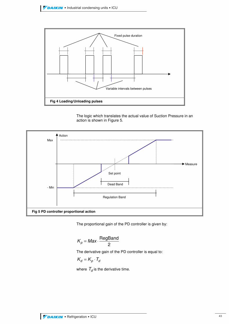
��������� ����������������������
������������������ ��
Fig 4 Loading/Unloading pulses
The logic which translates the actual value of Suction Pressure in an action is shown in Figure 5.
Fig 5 PD controller proportional action
The proportional gain of the PD controller is given by:
2RegBand
⋅= MaxKp
The derivative gain of the PD controller is equal to:
dpd TKK ⋅=
where dT is the derivative time.
Max
- Min
Set point
Dead Band
Fixed pulse duration
Variable intervals between pulses
Measure
Action
Regulation Band
ICU.pdf 51 26/01/2011 11:11:45
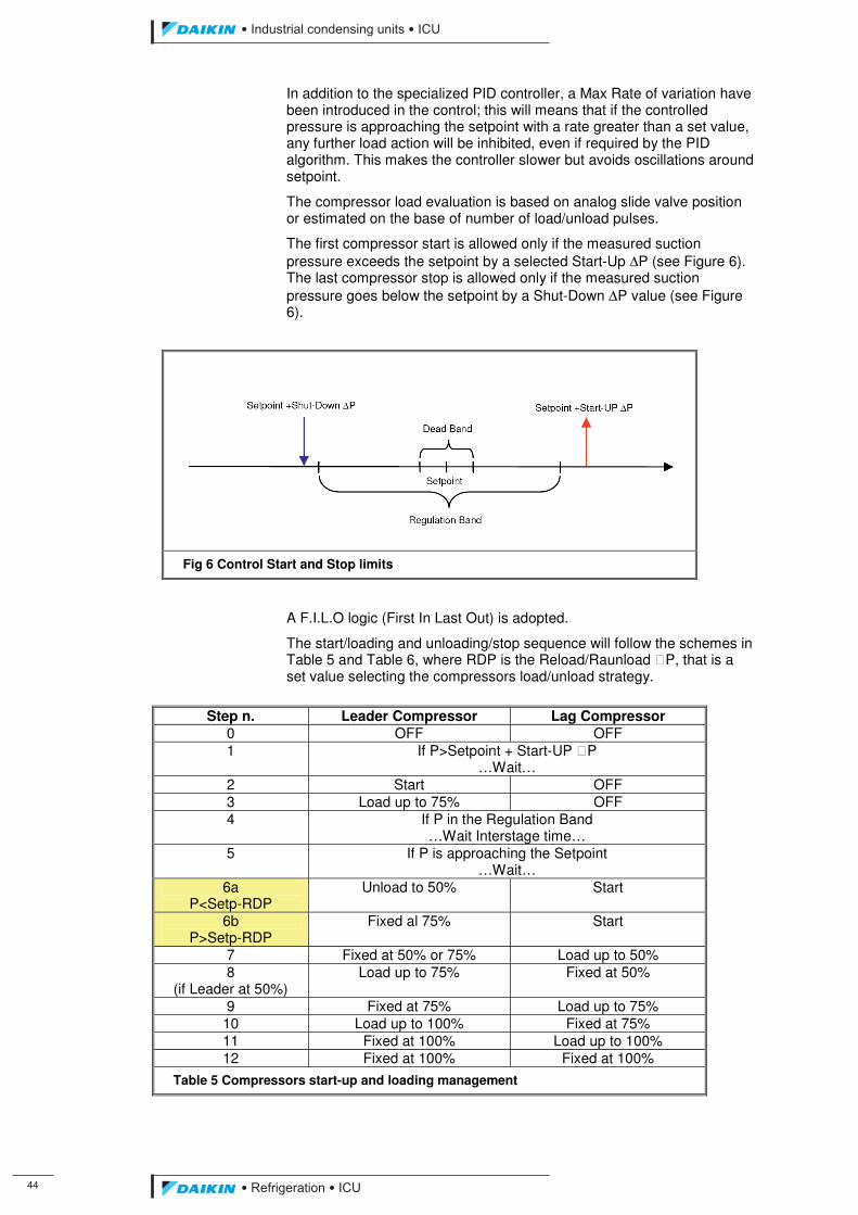
��
��������� ����������������������
������������������
In addition to the specialized PID controller, a Max Rate of variation have been introduced in the control; this will means that if the controlled pressure is approaching the setpoint with a rate greater than a set value, any further load action will be inhibited, even if required by the PID algorithm. This makes the controller slower but avoids oscillations around setpoint.
The compressor load evaluation is based on analog slide valve position or estimated on the base of number of load/unload pulses.
The first compressor start is allowed only if the measured suction pressure exceeds the setpoint by a selected Start-Up ΔP (see Figure 6). The last compressor stop is allowed only if the measured suction pressure goes below the setpoint by a Shut-Down ΔP value (see Figure 6).
Fig 6 Control Start and Stop limits
A F.I.L.O logic (First In Last Out) is adopted.
The start/loading and unloading/stop sequence will follow the schemes in Table 5 and Table 6, where RDP is the Reload/Raunload �P, that is a set value selecting the compressors load/unload strategy.
Step n. Leader Compressor Lag Compressor
0 OFF OFF 1 If P>Setpoint + Start-UP �P
…Wait… 2 Start OFF 3 Load up to 75% OFF 4 If P in the Regulation Band
…Wait Interstage time… 5 If P is approaching the Setpoint
…Wait… 6a
P<Setp-RDP Unload to 50% Start
6b P>Setp-RDP
Fixed al 75% Start
7 Fixed at 50% or 75% Load up to 50% 8
(if Leader at 50%) Load up to 75% Fixed at 50%
9 Fixed at 75% Load up to 75% 10 Load up to 100% Fixed at 75% 11 Fixed at 100% Load up to 100% 12 Fixed at 100% Fixed at 100%
Table 5 Compressors start-up and loading management
ICU.pdf 52 26/01/2011 11:11:45
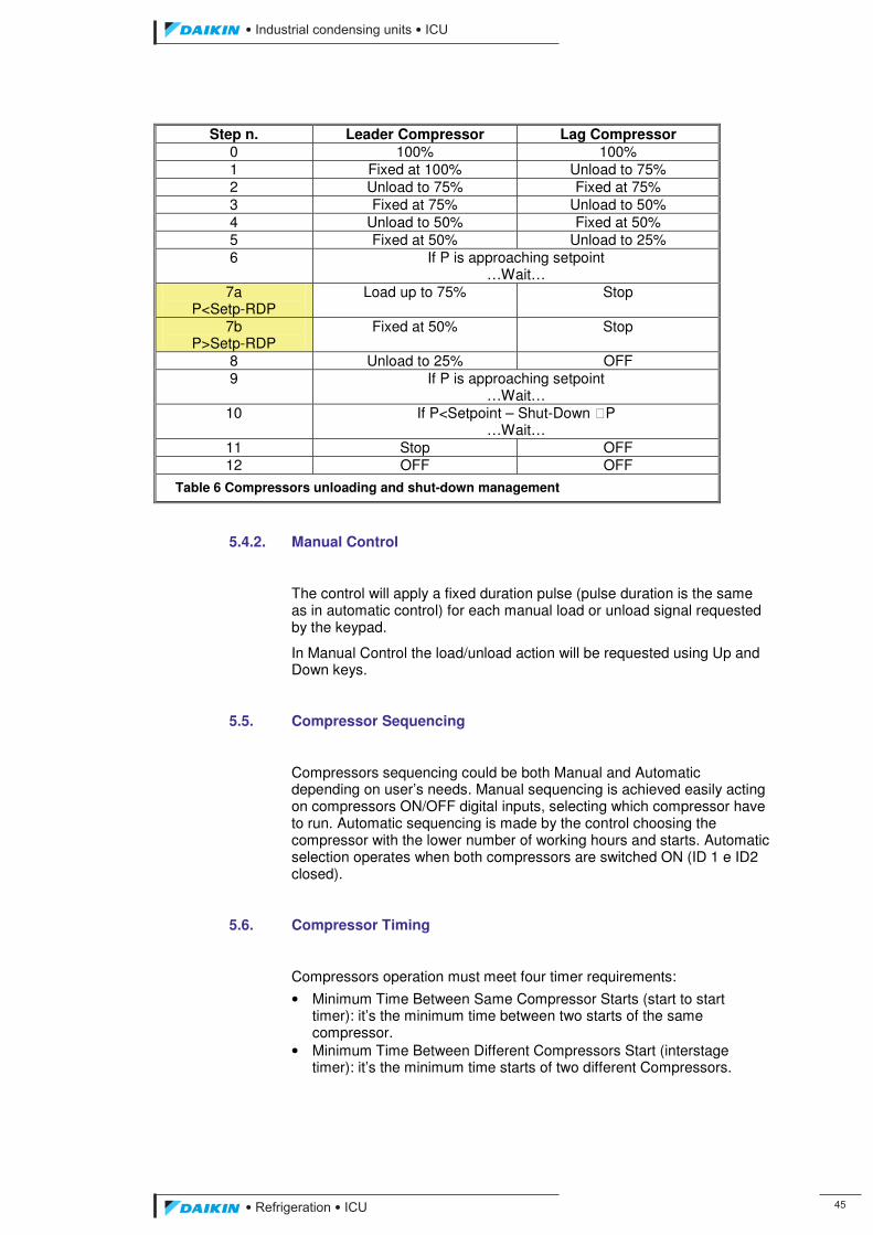
��������� ����������������������
������������������ ��
Step n. Leader Compressor Lag Compressor 0 100% 100% 1 Fixed at 100% Unload to 75% 2 Unload to 75% Fixed at 75% 3 Fixed at 75% Unload to 50% 4 Unload to 50% Fixed at 50% 5 Fixed at 50% Unload to 25% 6 If P is approaching setpoint
…Wait… 7a
P<Setp-RDP Load up to 75% Stop
7b P>Setp-RDP
Fixed at 50% Stop
8 Unload to 25% OFF 9 If P is approaching setpoint
…Wait… 10 If P<Setpoint – Shut-Down �P
…Wait… 11 Stop OFF 12 OFF OFF
Table 6 Compressors unloading and shut-down management
5.4.2. Manual Control
The control will apply a fixed duration pulse (pulse duration is the same as in automatic control) for each manual load or unload signal requested by the keypad.
In Manual Control the load/unload action will be requested using Up and Down keys.
5.5. Compressor Sequencing
Compressors sequencing could be both Manual and Automatic depending on user’s needs. Manual sequencing is achieved easily acting on compressors ON/OFF digital inputs, selecting which compressor have to run. Automatic sequencing is made by the control choosing the compressor with the lower number of working hours and starts. Automatic selection operates when both compressors are switched ON (ID 1 e ID2 closed).
5.6. Compressor Timing
Compressors operation must meet four timer requirements:
• Minimum Time Between Same Compressor Starts (start to start timer): it’s the minimum time between two starts of the same compressor.
• Minimum Time Between Different Compressors Start (interstage timer): it’s the minimum time starts of two different Compressors.
ICU.pdf 53 26/01/2011 11:11:46
��
��������� ����������������������
������������������
• Minimum Time Compressor ON (start to stop timer): it’s the minimum time the compressor will run; the compressor cannot be stopped (unless an alarm occurs) if the timer is not expired.
• Minimum Time Compressor OFF (stop to start timer): it’s the minimum time the compressor will be stopped; the compressor cannot be started if this timer is not expired.
5.7. Compressors Protections
To protect compressors against loss of lubrication, the compressor pressure ratio is continuously checked; a minimum value is set for compressor minimum and maximum load; for intermediate compressor loads a linear interpolation is implemented.
The low pressure ratio alarm will occur if the pressure ratio remains lower than the minimum value at rated compressor capacity for a certain time (set by manufacturer).
During the start up the compressor is completely downloaded and its loading will not be enabled until the pressure ratio exceeds a set value (default equal to 2).
5.8. Compressors Start-Up Procedure
Start up procedure for this kind of unit will be very easy because no pre-emptying procedure could be performed. The compressor started is kept at its minimum load for an adjustable time.
As this timer expires compressor management is modified for suction pressure control.
5.8.1. High Oil Level Switch
Compressors start will not be allowed if the oil level switch opens. If this happens the compressor will be disabled until the switch closes. This condition will be ignored if the compressor is running.
5.9. Compressor Shut-Down procedure
When the shut-down of a compressor is required, the compressor is completely downloaded keeping the unload solenoid valve energized for an adjustable time. Once the timer has expired and the compressor is at its minimum load, it is switched off and starts its recycle time.
ICU.pdf 54 26/01/2011 11:11:46
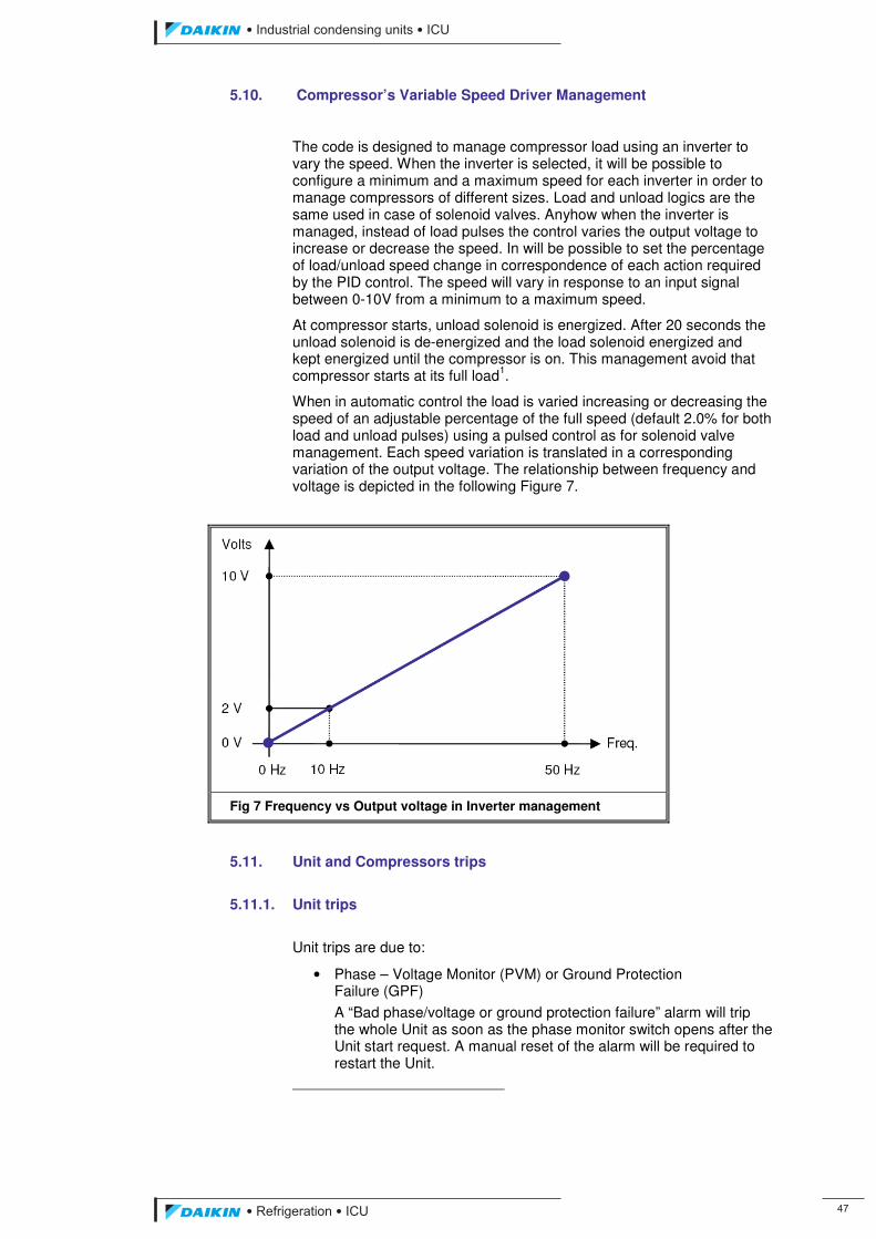
��������� ����������������������
������������������ ��
5.10. Compressor’s Variable Speed Driver Management
The code is designed to manage compressor load using an inverter to vary the speed. When the inverter is selected, it will be possible to configure a minimum and a maximum speed for each inverter in order to manage compressors of different sizes. Load and unload logics are the same used in case of solenoid valves. Anyhow when the inverter is managed, instead of load pulses the control varies the output voltage to increase or decrease the speed. In will be possible to set the percentage of load/unload speed change in correspondence of each action required by the PID control. The speed will vary in response to an input signal between 0-10V from a minimum to a maximum speed.
At compressor starts, unload solenoid is energized. After 20 seconds the unload solenoid is de-energized and the load solenoid energized and kept energized until the compressor is on. This management avoid that compressor starts at its full load1.
When in automatic control the load is varied increasing or decreasing the speed of an adjustable percentage of the full speed (default 2.0% for both load and unload pulses) using a pulsed control as for solenoid valve management. Each speed variation is translated in a corresponding variation of the output voltage. The relationship between frequency and voltage is depicted in the following Figure 7.
Fig 7 Frequency vs Output voltage in Inverter management
5.11. Unit and Compressors trips
5.11.1. Unit trips
Unit trips are due to:
• Phase – Voltage Monitor (PVM) or Ground Protection Failure (GPF)
A “Bad phase/voltage or ground protection failure” alarm will trip the whole Unit as soon as the phase monitor switch opens after the Unit start request. A manual reset of the alarm will be required to restart the Unit.
ICU.pdf 55 26/01/2011 11:11:46
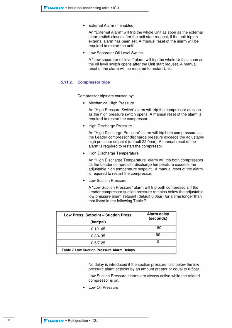
��
��������� ����������������������
������������������
• External Alarm (if enabled)
An “External Alarm” will trip the whole Unit as soon as the external alarm switch closes after the unit start request, if the unit trip on external alarm has been set. A manual reset of the alarm will be required to restart the unit.
• Low Separator Oil Level Switch
A “Low separator oil level” alarm will trip the whole Unit as soon as the oil level switch opens after the Unit start request. A manual reset of the alarm will be required to restart Unit.
5.11.2. Compressor trips
Compressor trips are caused by:
• Mechanical High Pressure
An “High Pressure Switch” alarm will trip the compressor as soon as the high pressure switch opens. A manual reset of the alarm is required to restart the compressor.
• High Discharge Pressure
An “High Discharge Pressure” alarm will trip both compressors as the Leader compressor discharge pressure exceeds the adjustable high pressure setpoint (default 22.0bar). A manual reset of the alarm is required to restart the compressor.
• High Discharge Temperature
An “High Discharge Temperature” alarm will trip both compressors as the Leader compressor discharge temperature exceeds the adjustable high temperature setpoint. A manual reset of the alarm is required to restart the compressor.
• Low Suction Pressure
A “Low Suction Pressure” alarm will trip both compressors if the Leader compressor suction pressure remains below the adjustable low pressure alarm setpoint (default 0.0bar) for a time longer than that listed in the following Table 7.
Low Press. Setpoint – Suction Press.
(bar/psi)
Alarm delay (seconds)
0.1/1.45 180
0.3/4.35 90
0.5/7.25 0
Table 7 Low Suction Pressure Alarm Delays
No delay is introduced if the suction pressure falls below the low pressure alarm setpoint by an amount greater or equal to 0.5bar.
Low Suction Pressure alarms are always active while the related compressor is on.
• Low Oil Pressure
ICU.pdf 56 26/01/2011 11:11:46
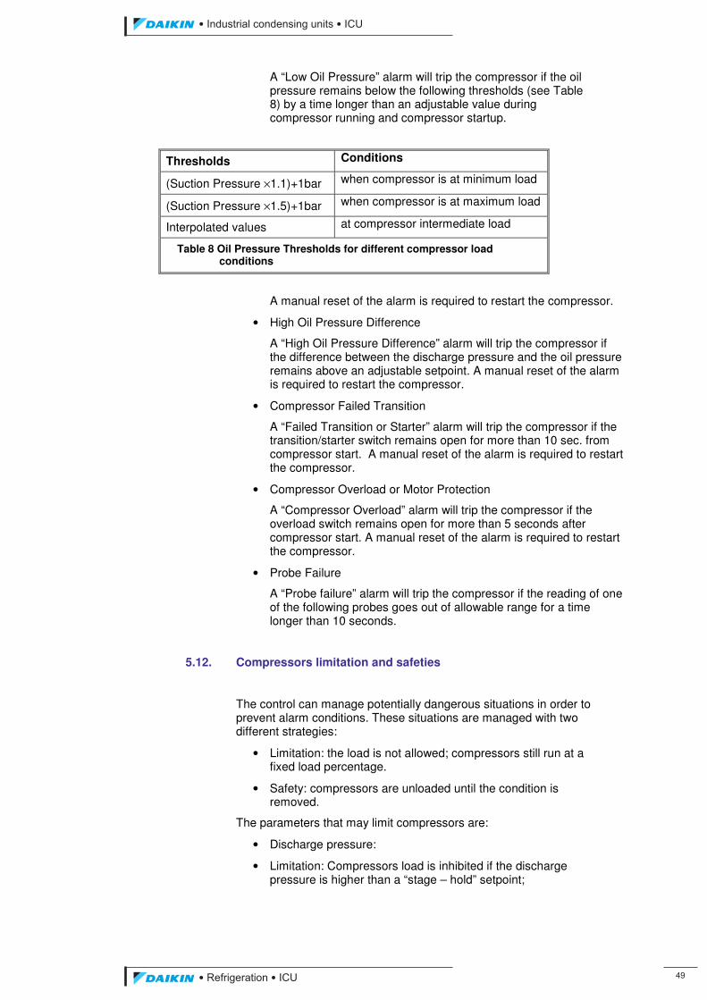
��������� ����������������������
������������������ ��
A “Low Oil Pressure” alarm will trip the compressor if the oil pressure remains below the following thresholds (see Table 8) by a time longer than an adjustable value during compressor running and compressor startup.
Thresholds Conditions
(Suction Pressure ×1.1)+1bar when compressor is at minimum load
(Suction Pressure ×1.5)+1bar when compressor is at maximum load
Interpolated values at compressor intermediate load
Table 8 Oil Pressure Thresholds for different compressor load conditions
A manual reset of the alarm is required to restart the compressor.
• High Oil Pressure Difference
A “High Oil Pressure Difference” alarm will trip the compressor if the difference between the discharge pressure and the oil pressure remains above an adjustable setpoint. A manual reset of the alarm is required to restart the compressor.
• Compressor Failed Transition
A “Failed Transition or Starter” alarm will trip the compressor if the transition/starter switch remains open for more than 10 sec. from compressor start. A manual reset of the alarm is required to restart the compressor.
• Compressor Overload or Motor Protection
A “Compressor Overload” alarm will trip the compressor if the overload switch remains open for more than 5 seconds after compressor start. A manual reset of the alarm is required to restart the compressor.
• Probe Failure
A “Probe failure” alarm will trip the compressor if the reading of one of the following probes goes out of allowable range for a time longer than 10 seconds.
5.12. Compressors limitation and safeties
The control can manage potentially dangerous situations in order to prevent alarm conditions. These situations are managed with two different strategies:
• Limitation: the load is not allowed; compressors still run at a fixed load percentage.
• Safety: compressors are unloaded until the condition is removed.
The parameters that may limit compressors are:
• Discharge pressure:
• Limitation: Compressors load is inhibited if the discharge pressure is higher than a “stage – hold” setpoint;
ICU.pdf 57 26/01/2011 11:11:46
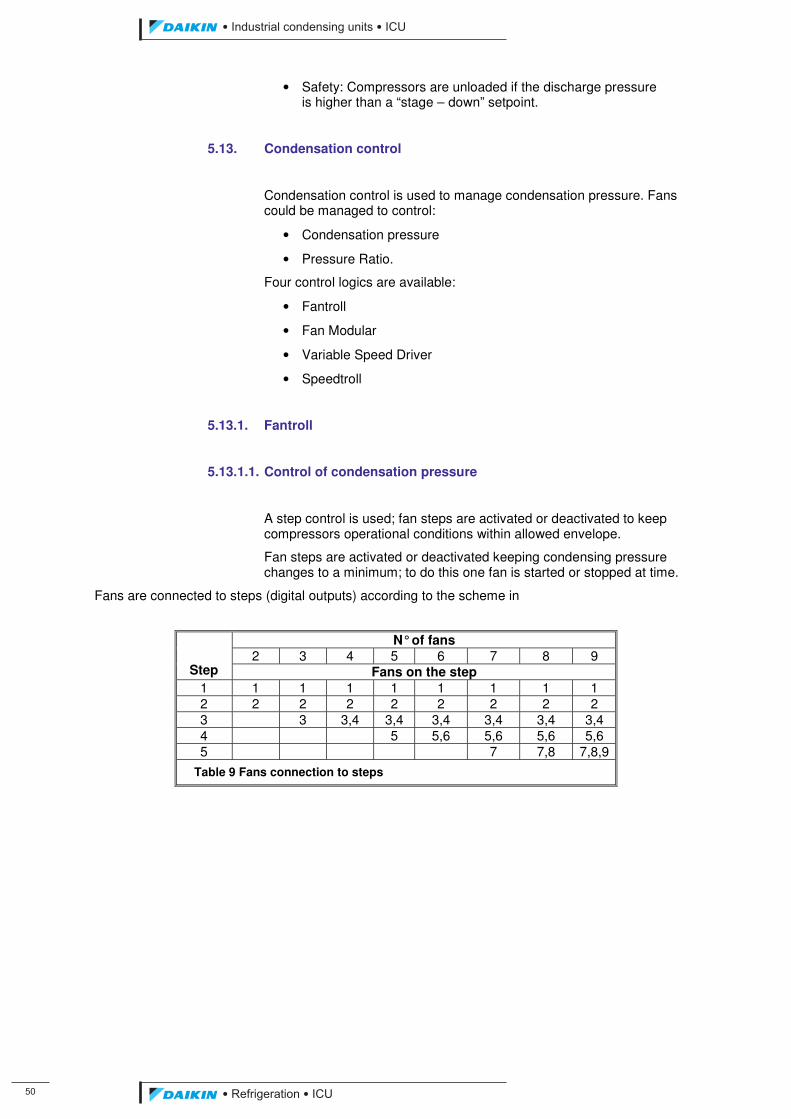
�
��������� ����������������������
������������������
• Safety: Compressors are unloaded if the discharge pressure is higher than a “stage – down” setpoint.
5.13. Condensation control
Condensation control is used to manage condensation pressure. Fans could be managed to control:
• Condensation pressure
• Pressure Ratio.
Four control logics are available:
• Fantroll
• Fan Modular
• Variable Speed Driver
• Speedtroll
5.13.1. Fantroll
5.13.1.1. Control of condensation pressure
A step control is used; fan steps are activated or deactivated to keep compressors operational conditions within allowed envelope.
Fan steps are activated or deactivated keeping condensing pressure changes to a minimum; to do this one fan is started or stopped at time.
Fans are connected to steps (digital outputs) according to the scheme in
N° of fans 2 3 4 5 6 7 8 9
Step Fans on the step 1 1 1 1 1 1 1 1 1 2 2 2 2 2 2 2 2 2 3 3 3,4 3,4 3,4 3,4 3,4 3,4 4 5 5,6 5,6 5,6 5,6 5 7 7,8 7,8,9
Table 9 Fans connection to steps
ICU.pdf 58 26/01/2011 11:11:46
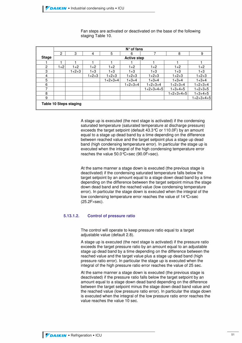
��������� ����������������������
������������������ ��
Fan steps are activated or deactivated on the base of the following staging Table 10.
N° of fans 2 3 4 5 6 7 8 9
Stage Active step 1 1 1 1 1 1 1 1 1 2 1+2 1+2 1+2 1+2 1+2 1+2 1+2 1+2 3 1+2+3 1+3 1+3 1+3 1+3 1+3 1+3 4 1+2+3 1+2+3 1+2+3 1+2+3 1+2+3 1+2+3 5 1+2+3+4 1+3+4 1+3+4 1+3+4 1+3+4 6 1+2+3+4 1+2+3+4 1+2+3+4 1+2+3+4 7 1+2+3+4+5 1+3+4+5 1+2+3+5 8 1+2+3+4+5 1+3+4+5 9 1+2+3+4+5
Table 10 Steps staging
A stage up is executed (the next stage is activated) if the condensing saturated temperature (saturated temperature at discharge pressure) exceeds the target setpoint (default 43.3°C or 110.0F) by an amount equal to a stage up dead band by a time depending on the difference between reached value and the target setpoint plus a stage up dead band (high condensing temperature error). In particular the stage up is executed when the integral of the high condensing temperature error reaches the value 50.0°C×sec (90.0F×sec).
At the same manner a stage down is executed (the previous stage is deactivated) if the condensing saturated temperature falls below the target setpoint by an amount equal to a stage down dead band by a time depending on the difference between the target setpoint minus the stage down dead band and the reached value (low condensing temperature error). In particular the stage down is executed when the integral of the low condensing temperature error reaches the value of 14°C×sec (25.2F×sec).
5.13.1.2. Control of pressure ratio
The control will operate to keep pressure ratio equal to a target adjustable value (default 2.8).
A stage up is executed (the next stage is activated) if the pressure ratio exceeds the target pressure ratio by an amount equal to an adjustable stage up dead band by a time depending on the difference between the reached value and the target value plus a stage up dead band (high pressure ratio error). In particular the stage up is executed when the integral of the high pressure ratio error reaches the value of 25 sec.
At the same manner a stage down is executed (the previous stage is deactivated) if the pressure ratio falls below the target setpoint by an amount equal to a stage down dead band depending on the difference between the target setpoint minus the stage down dead band value and the reached value (low pressure ratio error). In particular the stage down is executed when the integral of the low pressure ratio error reaches the value reaches the value 10 sec.
ICU.pdf 59 26/01/2011 11:11:46
��
��������� ����������������������
������������������
The pressure ratio integral error is reset to zero when the condensing temperature is within the dead band or a new stage is activated.
Each fan stage will have its own adjustable stage up and stage down (default 0.2) and stage down (default 0.2) dead band.
5.13.2. Fan Modular
The fan modular method will work at the same way of Fantroll method (staging sequence), but it will use an analog output instead of digital outputs. In particular the analog output will assume a value, in volts, equal to the stage number.
5.13.3. Variable Speed Drive
A continuous control is used; fans speed is modulated to keep saturated condensation pressure at a setpoint. A PID control is used to allow a stable operation.
A Fan Silent Mode function (FSM) is implemented on units with Variable Speed Driver (VSD) to keep fan speed below a set value during some specific periods.
When the system is operating, either if it is controlling the condensation pressure, the pressure ratio or the pressure difference, the PID proportional gain is positive (the higher the input the higher the output).
5.13.4. Speedtroll
A mixed step – VSD control are used; first fan step is managed using a VSD (with related PID control), other steps are activated as in the step control, only if cumulated stage-up and stage-down error is reached and the VSD output is at maximum or minimum respectively.
ICU.pdf 60 26/01/2011 11:11:46
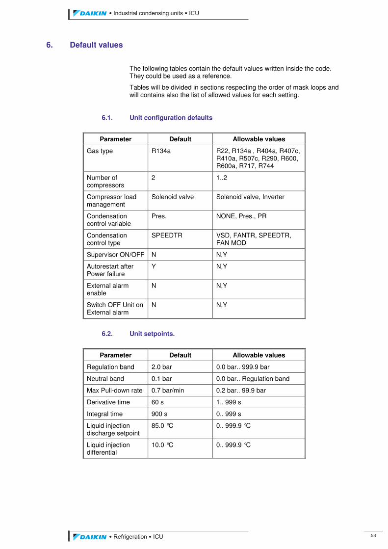
��������� ����������������������
������������������ ��
6. Default values
The following tables contain the default values written inside the code. They could be used as a reference.
Tables will be divided in sections respecting the order of mask loops and will contains also the list of allowed values for each setting.
6.1. Unit configuration defaults
Parameter Default Allowable values
Gas type R134a R22, R134a , R404a, R407c, R410a, R507c, R290, R600, R600a, R717, R744
Number of compressors
2 1..2
Compressor load management
Solenoid valve Solenoid valve, Inverter
Condensation control variable
Pres. NONE, Pres., PR
Condensation control type
SPEEDTR VSD, FANTR, SPEEDTR, FAN MOD
Supervisor ON/OFF N N,Y
Autorestart after Power failure
Y N,Y
External alarm enable
N N,Y
Switch OFF Unit on External alarm
N N,Y
6.2. Unit setpoints.
Parameter Default Allowable values
Regulation band 2.0 bar 0.0 bar.. 999.9 bar
Neutral band 0.1 bar 0.0 bar.. Regulation band
Max Pull-down rate 0.7 bar/min 0.2 bar.. 99.9 bar
Derivative time 60 s 1.. 999 s
Integral time 900 s 0.. 999 s
Liquid injection discharge setpoint
85.0 °C 0.. 999.9 °C
Liquid injection differential
10.0 °C 0.. 999.9 °C
ICU.pdf 61 26/01/2011 11:11:46
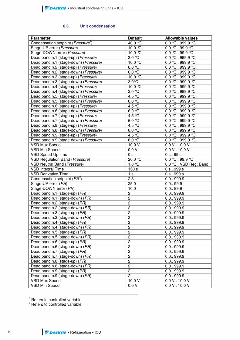
��
��������� ����������������������
������������������
6.3. Unit condensation
Parameter Default Allowable values Condensation setpoint (Pressure2) 40.0 °C 0.0 °C.. 999.9 °C Stage-UP error (Pressure) 10.0 °C 0.0 °C.. 99.9 °C Stage-DOWN error (Pressure) 10.0 °C 0.0 °C.. 99.9 °C Dead band n.1 (stage-up) (Pressure) 3.0 °C 0.0 °C.. 999.9 °C Dead band n.1 (stage-down) (Pressure) 10.0 °C 0.0 °C.. 999.9 °C Dead band n.2 (stage-up) (Pressure) 6.0 °C 0.0 °C.. 999.9 °C Dead band n.2 (stage-down) (Pressure) 6.0 °C 0.0 °C.. 999.9 °C Dead band n.3 (stage-up) (Pressure) 10.0 °C 0.0 °C.. 999.9 °C Dead band n.3 (stage-down) (Pressure) 3.0°C 0.0 °C.. 999.9 °C Dead band n.4 (stage-up) (Pressure) 10.0 °C 0.0 °C.. 999.9 °C Dead band n.4 (stage-down) (Pressure) 2.0 °C 0.0 °C.. 999.9 °C Dead band n.5 (stage-up) (Pressure) 4.5 °C 0.0 °C.. 999.9 °C Dead band n.5 (stage-down) (Pressure) 6.0 °C 0.0 °C.. 999.9 °C Dead band n.6 (stage-up) (Pressure) 4.5 °C 0.0 °C.. 999.9 °C Dead band n.6 (stage-down) (Pressure) 6.0 °C 0.0 °C.. 999.9 °C Dead band n.7 (stage-up) (Pressure) 4.5 °C 0.0 °C.. 999.9 °C Dead band n.7 (stage-down) (Pressure) 6.0 °C 0.0 °C.. 999.9 °C Dead band n.8 (stage-up) (Pressure) 4.5 °C 0.0 °C.. 999.9 °C Dead band n.8 (stage-down) (Pressure) 6.0 °C 0.0 °C.. 999.9 °C Dead band n.9 (stage-up) (Pressure) 4.5 °C 0.0 °C.. 999.9 °C Dead band n.9 (stage-down) (Pressure) 6.0 °C 0.0 °C.. 999.9 °C VSD Max Speed 10.0 V 0.0 V.. 10.0 V VSD Min Speed 0.0 V 0.0 V.. 10.0 V VSD Speed-Up time 0 s 0 s.. 99 s VSD Regulation Band (Pressure) 20.0 °C 0.0 °C.. 99.9 °C VSD Neutral Band (Pressure) 1.0 °C 0.0 °C.. VSD Reg. Band VSD Integral Time 150 s 0 s.. 999 s VSD Derivative Time 1 s 0 s.. 999 s Condensation setpoint (PR3) 2.8 0.0.. 999.9 Stage-UP error (PR) 25.0 0.0.. 99.9 Stage-DOWN error (PR) 10.0 0.0.. 99.9 Dead band n.1 (stage-up) (PR) 2 0.0.. 999.9 Dead band n.1 (stage-down) (PR) 2 0.0.. 999.9 Dead band n.2 (stage-up) (PR) 2 0.0.. 999.9 Dead band n.2 (stage-down) (PR) 2 0.0.. 999.9 Dead band n.3 (stage-up) (PR) 2 0.0.. 999.9 Dead band n.3 (stage-down) (PR) 2 0.0.. 999.9 Dead band n.4 (stage-up) (PR) 2 0.0.. 999.9 Dead band n.4 (stage-down) (PR) 2 0.0.. 999.9 Dead band n.5 (stage-up) (PR) 2 0.0.. 999.9 Dead band n.5 (stage-down) (PR) 2 0.0.. 999.9 Dead band n.6 (stage-up) (PR) 2 0.0.. 999.9 Dead band n.6 (stage-down) (PR) 2 0.0.. 999.9 Dead band n.7 (stage-up) (PR) 2 0.0.. 999.9 Dead band n.7 (stage-down) (PR) 2 0.0.. 999.9 Dead band n.8 (stage-up) (PR) 2 0.0.. 999.9 Dead band n.8 (stage-down) (PR) 2 0.0.. 999.9 Dead band n.9 (stage-up) (PR) 2 0.0.. 999.9 Dead band n.9 (stage-down) (PR) 2 0.0.. 999.9 VSD Max Speed 10.0 V 0.0 V.. 10.0 V VSD Min Speed 0.0 V 0.0 V.. 10.0 V
2 Refers to controlled variable 3 Refers to controlled variable
ICU.pdf 62 26/01/2011 11:11:46
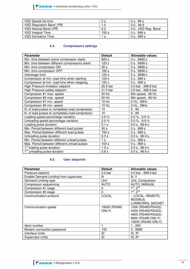
��������� ����������������������
������������������ ��
VSD Speed-Up time 0 s 0 s.. 99 s VSD Regulation Band (PR) 1.0 0.0.. 99.9 VSD Neutral Band (PR) 0.2 0.0.. VSD Reg. Band VSD Integral Time 150 s 0 s.. 999 s VSD Derivative Time 1 s 0 s.. 999 s
6.4. Compressors settings
Parameter Default Allowable values Min. time between same compressor starts 600 s 0 s.. 9999 s Min. time between different compressors starts 120 s 0 s.. 9999 s Min. time compressor ON 30 s 0 s.. 9999 s Min. time compressor OFF 180 s 0 s.. 9999 s Interstage time 120 s 0 s.. 9999 s Compressor at min. load time when starting 120 s 0 s.. 999 s Compressor at min. load time when stopping 120 s 0 s.. 999 s High Pressure limitation setpoint 20.5 bar 0.0 bar.. 999.9 bar High Pressure safety setpoint 21.5 bar 0.0 bar.. 999.9 bar Compressor #1 max. speed 50 Hz Min speed.. 99 Hz Compressor #2 max. speed 50 Hz Min speed.. 99 Hz Compressor #1 min. speed 10 Hz 0 Hz.. 99Hz Compressor #2 min. speed 10 Hz 0 Hz.. 99Hz N. of load pulses to completely load compressor 10 0.. 99 N. of load pulses to completely load compressor 10 0.. 99 Loading speed percentage variation 2.0 % 0.0 %.. 9.9 % Unloading speed percentage variation 2.0 % 0.0 %.. 9.9 % Loading pulse duration 0.1 s 0.0 s.. 99.9 s Min. Period between different load pulses 30 s 0 s.. 999 s Max. Period between different load pulses 150 s 0 s.. 999 s Unloading pulse duration 0.3 s 0.0 s.. 99.9 s Min. Period between different unload pulses 1 s 0 s.. 999 s Max. Period between different unload pulses 150 s 0 s.. 999 s 1st loading pulse duration 1.0 s 0.0 s.. 99.9 s 1st unloading pulse duration 0.8 s 0.0 s.. 99.9 s
6.5. User setpoints
Parameter Default Allowable values Pressure setpoint 3.0 bar 0.0 bar.. 999.9 bar Enable Demand Limiting from supervisor N N, Y Demand Limiting type Unit Unit, Compressor Compressor sequencing AUTO AUTO, MANUAL Compressor #1 stage 0 1st, 2nd Compressor #2 stage 0 1st, 2nd Communication protocol LOCAL -, LOCAL, REMOTE,
MODBUS, LONWORKS, BACNET
Communication speed 19200 (RS485 ONLY)
1200 (RS485/RS422), 2400 (RS485/RS422), 4800 (RS485/RS422), 9600 (RS485 ONLY), 19200 (RS485 ONLY)
Ident number 1 1.. 200 Modem connection password 152 0.. 9999 Interface Units SI SI, IP Supervisor Units SI SI, IP
ICU.pdf 63 26/01/2011 11:11:46
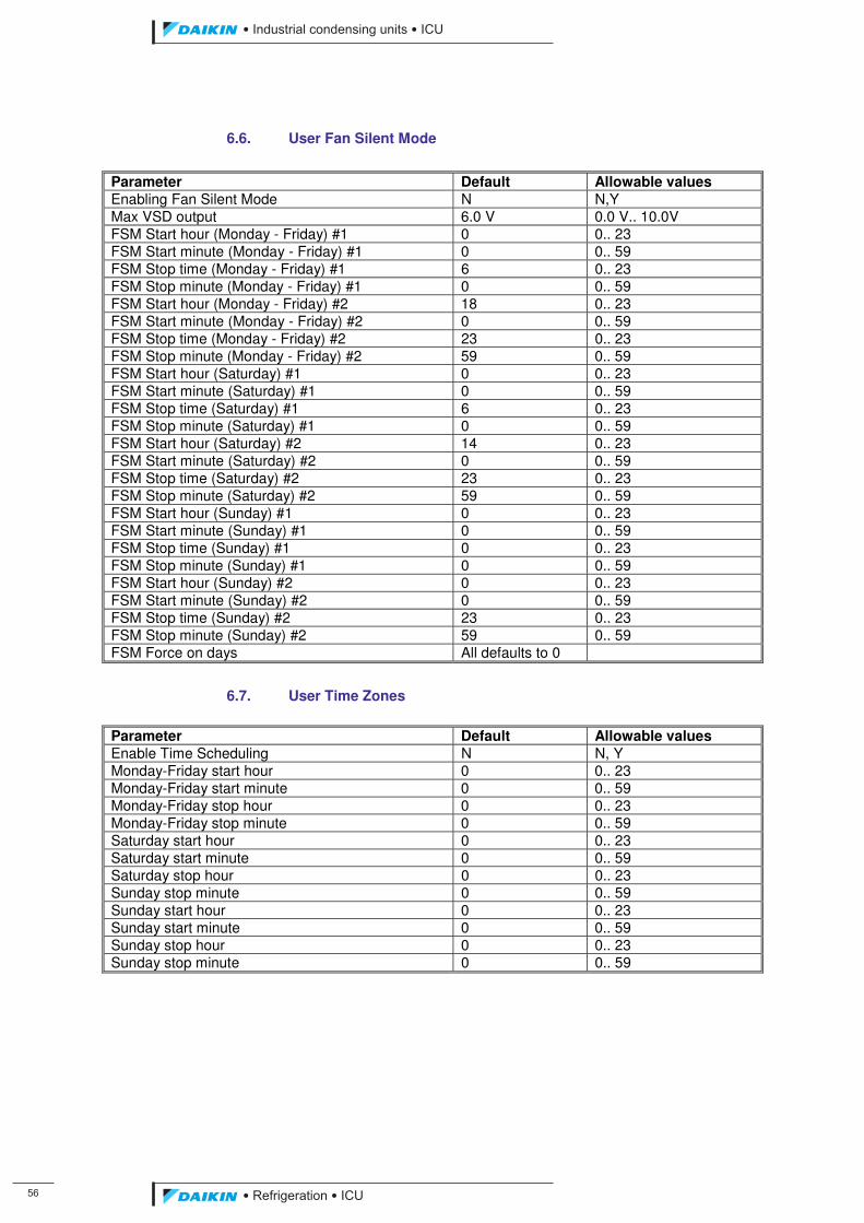
��
��������� ����������������������
������������������
6.6. User Fan Silent Mode
Parameter Default Allowable values Enabling Fan Silent Mode N N,Y Max VSD output 6.0 V 0.0 V.. 10.0V FSM Start hour (Monday - Friday) #1 0 0.. 23 FSM Start minute (Monday - Friday) #1 0 0.. 59 FSM Stop time (Monday - Friday) #1 6 0.. 23 FSM Stop minute (Monday - Friday) #1 0 0.. 59 FSM Start hour (Monday - Friday) #2 18 0.. 23 FSM Start minute (Monday - Friday) #2 0 0.. 59 FSM Stop time (Monday - Friday) #2 23 0.. 23 FSM Stop minute (Monday - Friday) #2 59 0.. 59 FSM Start hour (Saturday) #1 0 0.. 23 FSM Start minute (Saturday) #1 0 0.. 59 FSM Stop time (Saturday) #1 6 0.. 23 FSM Stop minute (Saturday) #1 0 0.. 59 FSM Start hour (Saturday) #2 14 0.. 23 FSM Start minute (Saturday) #2 0 0.. 59 FSM Stop time (Saturday) #2 23 0.. 23 FSM Stop minute (Saturday) #2 59 0.. 59 FSM Start hour (Sunday) #1 0 0.. 23 FSM Start minute (Sunday) #1 0 0.. 59 FSM Stop time (Sunday) #1 0 0.. 23 FSM Stop minute (Sunday) #1 0 0.. 59 FSM Start hour (Sunday) #2 0 0.. 23 FSM Start minute (Sunday) #2 0 0.. 59 FSM Stop time (Sunday) #2 23 0.. 23 FSM Stop minute (Sunday) #2 59 0.. 59 FSM Force on days All defaults to 0
6.7. User Time Zones
Parameter Default Allowable values Enable Time Scheduling N N, Y Monday-Friday start hour 0 0.. 23 Monday-Friday start minute 0 0.. 59 Monday-Friday stop hour 0 0.. 23 Monday-Friday stop minute 0 0.. 59 Saturday start hour 0 0.. 23 Saturday start minute 0 0.. 59 Saturday stop hour 0 0.. 23 Sunday stop minute 0 0.. 59 Sunday start hour 0 0.. 23 Sunday start minute 0 0.. 59 Sunday stop hour 0 0.. 23 Sunday stop minute 0 0.. 59
ICU.pdf 64 26/01/2011 11:11:46
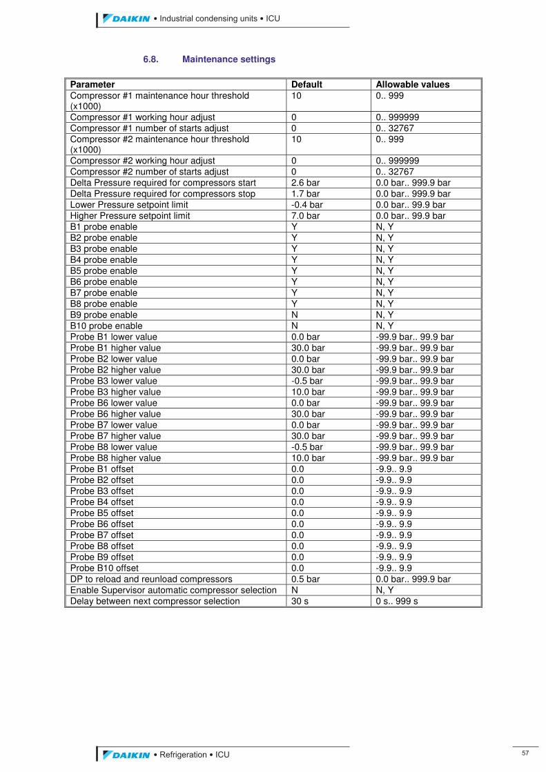
��������� ����������������������
������������������ ��
6.8. Maintenance settings Parameter Default Allowable values Compressor #1 maintenance hour threshold (x1000)
10 0.. 999
Compressor #1 working hour adjust 0 0.. 999999 Compressor #1 number of starts adjust 0 0.. 32767 Compressor #2 maintenance hour threshold (x1000)
10 0.. 999
Compressor #2 working hour adjust 0 0.. 999999 Compressor #2 number of starts adjust 0 0.. 32767 Delta Pressure required for compressors start 2.6 bar 0.0 bar.. 999.9 bar Delta Pressure required for compressors stop 1.7 bar 0.0 bar.. 999.9 bar Lower Pressure setpoint limit -0.4 bar 0.0 bar.. 99.9 bar Higher Pressure setpoint limit 7.0 bar 0.0 bar.. 99.9 bar B1 probe enable Y N, Y B2 probe enable Y N, Y B3 probe enable Y N, Y B4 probe enable Y N, Y B5 probe enable Y N, Y B6 probe enable Y N, Y B7 probe enable Y N, Y B8 probe enable Y N, Y B9 probe enable N N, Y B10 probe enable N N, Y Probe B1 lower value 0.0 bar -99.9 bar.. 99.9 bar Probe B1 higher value 30.0 bar -99.9 bar.. 99.9 bar Probe B2 lower value 0.0 bar -99.9 bar.. 99.9 bar Probe B2 higher value 30.0 bar -99.9 bar.. 99.9 bar Probe B3 lower value -0.5 bar -99.9 bar.. 99.9 bar Probe B3 higher value 10.0 bar -99.9 bar.. 99.9 bar Probe B6 lower value 0.0 bar -99.9 bar.. 99.9 bar Probe B6 higher value 30.0 bar -99.9 bar.. 99.9 bar Probe B7 lower value 0.0 bar -99.9 bar.. 99.9 bar Probe B7 higher value 30.0 bar -99.9 bar.. 99.9 bar Probe B8 lower value -0.5 bar -99.9 bar.. 99.9 bar Probe B8 higher value 10.0 bar -99.9 bar.. 99.9 bar Probe B1 offset 0.0 -9.9.. 9.9 Probe B2 offset 0.0 -9.9.. 9.9 Probe B3 offset 0.0 -9.9.. 9.9 Probe B4 offset 0.0 -9.9.. 9.9 Probe B5 offset 0.0 -9.9.. 9.9 Probe B6 offset 0.0 -9.9.. 9.9 Probe B7 offset 0.0 -9.9.. 9.9 Probe B8 offset 0.0 -9.9.. 9.9 Probe B9 offset 0.0 -9.9.. 9.9 Probe B10 offset 0.0 -9.9.. 9.9 DP to reload and reunload compressors 0.5 bar 0.0 bar.. 999.9 bar Enable Supervisor automatic compressor selection N N, Y Delay between next compressor selection 30 s 0 s.. 999 s
ICU.pdf 65 26/01/2011 11:11:46
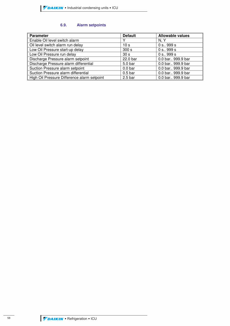
��
��������� ����������������������
������������������
6.9. Alarm setpoints Parameter Default Allowable values Enable Oil level switch alarm Y N, Y Oil level switch alarm run delay 10 s 0 s.. 999 s Low Oil Pressure start-up delay 300 s 0 s.. 999 s Low Oil Pressure run delay 30 s 0 s.. 999 s Discharge Pressure alarm setpoint 22.0 bar 0.0 bar.. 999.9 bar Discharge Pressure alarm differential 5.0 bar 0.0 bar.. 999.9 bar Suction Pressure alarm setpoint 0.0 bar 0.0 bar.. 999.9 bar Suction Pressure alarm differential 0.5 bar 0.0 bar.. 999.9 bar High Oil Pressure Difference alarm setpoint 2.5 bar 0.0 bar.. 999.9 bar
ICU.pdf 66 26/01/2011 11:11:46
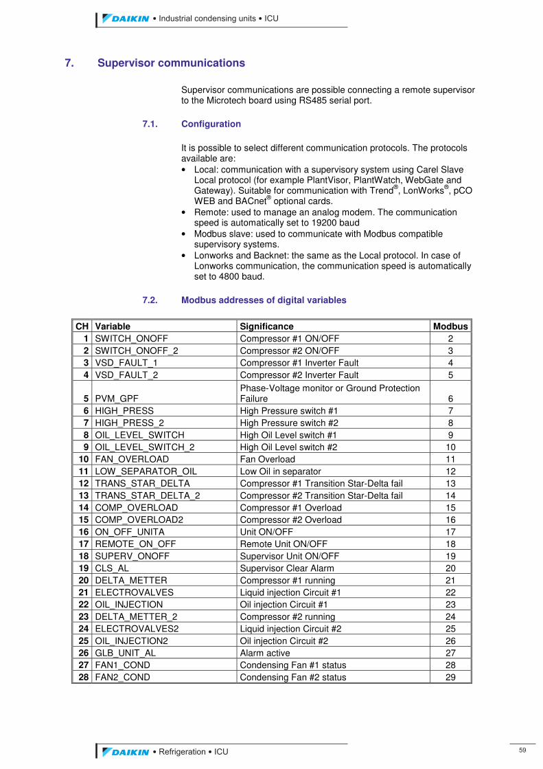
��������� ����������������������
������������������ ��
7. Supervisor communications
Supervisor communications are possible connecting a remote supervisor to the Microtech board using RS485 serial port.
7.1. Configuration
It is possible to select different communication protocols. The protocols available are: • Local: communication with a supervisory system using Carel Slave
Local protocol (for example PlantVisor, PlantWatch, WebGate and Gateway). Suitable for communication with Trend®, LonWorks®, pCO WEB and BACnet® optional cards.
• Remote: used to manage an analog modem. The communication speed is automatically set to 19200 baud
• Modbus slave: used to communicate with Modbus compatible supervisory systems.
• Lonworks and Backnet: the same as the Local protocol. In case of Lonworks communication, the communication speed is automatically set to 4800 baud.
7.2. Modbus addresses of digital variables
CH Variable Significance Modbus 1 SWITCH_ONOFF Compressor #1 ON/OFF 2 2 SWITCH_ONOFF_2 Compressor #2 ON/OFF 3 3 VSD_FAULT_1 Compressor #1 Inverter Fault 4 4 VSD_FAULT_2 Compressor #2 Inverter Fault 5
5 PVM_GPF Phase-Voltage monitor or Ground Protection Failure 6
6 HIGH_PRESS High Pressure switch #1 7 7 HIGH_PRESS_2 High Pressure switch #2 8 8 OIL_LEVEL_SWITCH High Oil Level switch #1 9 9 OIL_LEVEL_SWITCH_2 High Oil Level switch #2 10
10 FAN_OVERLOAD Fan Overload 11 11 LOW_SEPARATOR_OIL Low Oil in separator 12 12 TRANS_STAR_DELTA Compressor #1 Transition Star-Delta fail 13 13 TRANS_STAR_DELTA_2 Compressor #2 Transition Star-Delta fail 14 14 COMP_OVERLOAD Compressor #1 Overload 15 15 COMP_OVERLOAD2 Compressor #2 Overload 16 16 ON_OFF_UNITA Unit ON/OFF 17 17 REMOTE_ON_OFF Remote Unit ON/OFF 18 18 SUPERV_ONOFF Supervisor Unit ON/OFF 19 19 CLS_AL Supervisor Clear Alarm 20 20 DELTA_METTER Compressor #1 running 21 21 ELECTROVALVES Liquid injection Circuit #1 22 22 OIL_INJECTION Oil injection Circuit #1 23 23 DELTA_METTER_2 Compressor #2 running 24 24 ELECTROVALVES2 Liquid injection Circuit #2 25 25 OIL_INJECTION2 Oil injection Circuit #2 26 26 GLB_UNIT_AL Alarm active 27 27 FAN1_COND Condensing Fan #1 status 28 28 FAN2_COND Condensing Fan #2 status 29
ICU.pdf 67 26/01/2011 11:11:46
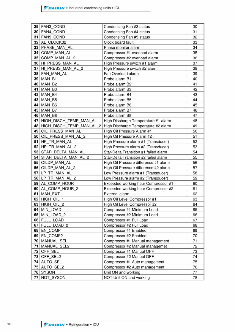
�
��������� ����������������������
������������������
29 FAN3_COND Condensing Fan #3 status 30 30 FAN4_COND Condensing Fan #4 status 31 31 FAN5_COND Condensing Fan #5 status 32 32 AL_CLOCK32 Clock board fault 33 33 PHASE_MAN_AL Phase monitor alarm 34 34 COMP_MAN_AL Compressor #1 overload alarm 35 35 COMP_MAN_AL_2 Compressor #2 overload alarm 36 36 HI_PRESS_MAN_AL High Pressure switch #1 alarm 37 37 HI_PRESS_MAN_AL_2 High Pressure switch #2 alarm 38 38 FAN_MAN_AL Fan Overload alarm 39 39 MAN_B1 Probe alarm B1 40 40 MAN_B2 Probe alarm B2 41 41 MAN_B3 Probe alarm B3 42 42 MAN_B4 Probe alarm B4 43 43 MAN_B5 Probe alarm B5 44 44 MAN_B6 Probe alarm B6 45 45 MAN_B7 Probe alarm B7 46 46 MAN_B8 Probe alarm B8 47 47 HIGH_DISCH_TEMP_MAN_AL High Discharge Temperature #1 alarm 48 48 HIGH_DISCH_TEMP_MAN_AL_2 High Discharge Temperature #2 alarm 49 49 OIL_PRESS_MAN_AL High Oil Pressure Alarm #1 50 50 OIL_PRESS_MAN_AL_2 High Oil Pressure Alarm #2 51 51 HP_TR_MAN_AL High Pressure alarm #1 (Transducer) 52 52 HP_TR_MAN_AL_2 High Pressure alarm #2 (Transducer) 53 53 STAR_DELTA_MAN_AL Star-Delta Transition #1 failed alarm 54 54 STAR_DELTA_MAN_AL_2 Star-Delta Transition #2 failed alarm 55 55 OILDP_MAN_AL High Oil Pressure difference #1 alarm 56 56 OILDP_MAN_AL_2 High Oil Pressure difference #2 alarm 57 57 LP_TR_MAN_AL Low Pressure alarm #1 (Transducer) 58 58 LP_TR_MAN_AL_2 Low Pressure alarm #2 (Transducer) 59 59 AL_COMP_HOUR Exceeded working hour Compressor #1 60 60 AL_COMP_HOUR_2 Exceeded working hour Compressor #2 61 61 MAN_EXT External alarm 62 62 HIGH_OIL_1 High Oil Level Compressor #1 63 63 HIGH_OIL_2 High Oil Level Compressor #2 64 64 MIN_LOAD Compressor #1 Minimum Load 65 65 MIN_LOAD_2 Compressor #2 Minimum Load 66 66 FULL_LOAD Compressor #1 Full Load 67 67 FULL_LOAD_2 Compressor #2 Full Load 68 68 EN_COMP Compressor #1 Enabled 69 69 EN_COMP2 Compressor #2 Enabled 70 70 MANUAL_SEL Compressor #1 Manual management 71 71 MANUAL_SEL2 Compressor #2 Manual managemet 72 72 OFF_SEL Compressor #1 Manual OFF 73 73 OFF_SEL2 Compressor #2 Manual OFF 74 74 AUTO_SEL Compressor #1 Auto management 75 75 AUTO_SEL2 Compressor #2 Auto management 76 76 SYSON Unit ON and working 77 77 NOT_SYSON NOT Unit ON and working 78
ICU.pdf 68 26/01/2011 11:11:46
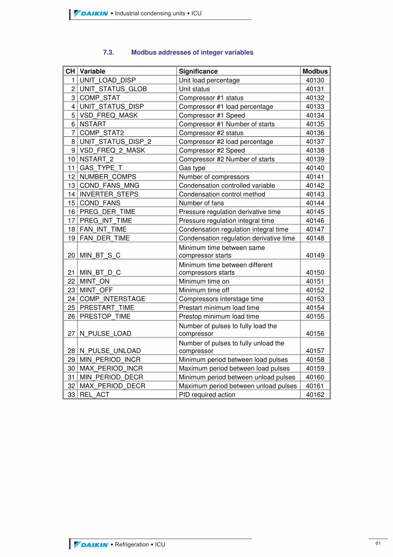
��������� ����������������������
������������������ ��
7.3. Modbus addresses of integer variables
CH Variable Significance Modbus 1 UNIT_LOAD_DISP Unit load percentage 40130 2 UNIT_STATUS_GLOB Unit status 40131 3 COMP_STAT Compressor #1 status 40132 4 UNIT_STATUS_DISP Compressor #1 load percentage 40133 5 VSD_FREQ_MASK Compressor #1 Speed 40134 6 NSTART Compressor #1 Number of starts 40135 7 COMP_STAT2 Compressor #2 status 40136 8 UNIT_STATUS_DISP_2 Compressor #2 load percentage 40137 9 VSD_FREQ_2_MASK Compressor #2 Speed 40138
10 NSTART_2 Compressor #2 Number of starts 40139 11 GAS_TYPE_T Gas type 40140 12 NUMBER_COMPS Number of compressors 40141 13 COND_FANS_MNG Condensation controlled variable 40142 14 INVERTER_STEPS Condensation control method 40143 15 COND_FANS Number of fans 40144 16 PREG_DER_TIME Pressure regulation derivative time 40145 17 PREG_INT_TIME Pressure regulation integral time 40146 18 FAN_INT_TIME Condensation regulation integral time 40147 19 FAN_DER_TIME Condensation regulation derivative time 40148
20 MIN_BT_S_C Minimum time between same compressor starts 40149
21 MIN_BT_D_C Minimum time between different compressors starts 40150
22 MINT_ON Minimum time on 40151 23 MINT_OFF Minimum time off 40152 24 COMP_INTERSTAGE Compressors interstage time 40153 25 PRESTART_TIME Prestart minimum load time 40154 26 PRESTOP_TIME Prestop minimum load time 40155
27 N_PULSE_LOAD Number of pulses to fully load the compressor 40156
28 N_PULSE_UNLOAD Number of pulses to fully unload the compressor 40157
29 MIN_PERIOD_INCR Minimum period between load pulses 40158 30 MAX_PERIOD_INCR Maximum period between load pulses 40159 31 MIN_PERIOD_DECR Minimum period between unload pulses 40160 32 MAX_PERIOD_DECR Maximum period between unload pulses 40161 33 REL_ACT PID required action 40162
ICU.pdf 69 26/01/2011 11:11:47
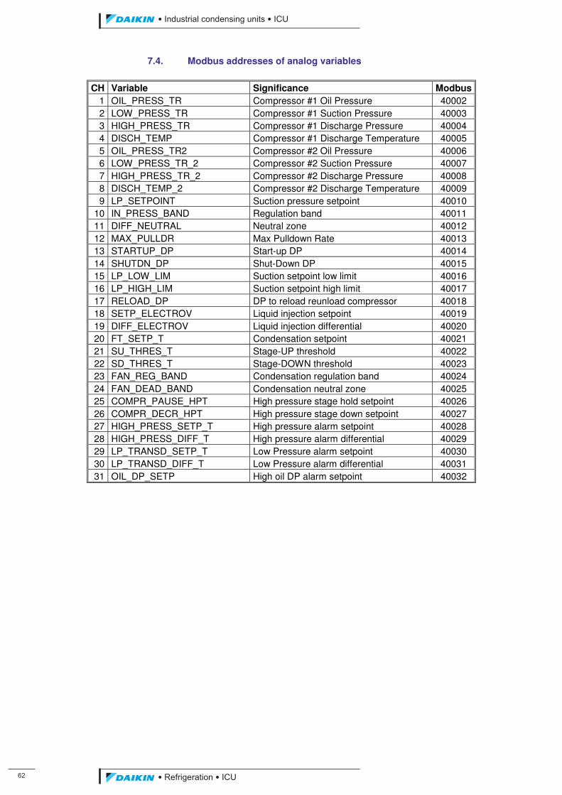
��
��������� ����������������������
������������������
7.4. Modbus addresses of analog variables
CH Variable Significance Modbus 1 OIL_PRESS_TR Compressor #1 Oil Pressure 40002 2 LOW_PRESS_TR Compressor #1 Suction Pressure 40003 3 HIGH_PRESS_TR Compressor #1 Discharge Pressure 40004 4 DISCH_TEMP Compressor #1 Discharge Temperature 40005 5 OIL_PRESS_TR2 Compressor #2 Oil Pressure 40006 6 LOW_PRESS_TR_2 Compressor #2 Suction Pressure 40007 7 HIGH_PRESS_TR_2 Compressor #2 Discharge Pressure 40008 8 DISCH_TEMP_2 Compressor #2 Discharge Temperature 40009 9 LP_SETPOINT Suction pressure setpoint 40010
10 IN_PRESS_BAND Regulation band 40011 11 DIFF_NEUTRAL Neutral zone 40012 12 MAX_PULLDR Max Pulldown Rate 40013 13 STARTUP_DP Start-up DP 40014 14 SHUTDN_DP Shut-Down DP 40015 15 LP_LOW_LIM Suction setpoint low limit 40016 16 LP_HIGH_LIM Suction setpoint high limit 40017 17 RELOAD_DP DP to reload reunload compressor 40018 18 SETP_ELECTROV Liquid injection setpoint 40019 19 DIFF_ELECTROV Liquid injection differential 40020 20 FT_SETP_T Condensation setpoint 40021 21 SU_THRES_T Stage-UP threshold 40022 22 SD_THRES_T Stage-DOWN threshold 40023 23 FAN_REG_BAND Condensation regulation band 40024 24 FAN_DEAD_BAND Condensation neutral zone 40025 25 COMPR_PAUSE_HPT High pressure stage hold setpoint 40026 26 COMPR_DECR_HPT High pressure stage down setpoint 40027 27 HIGH_PRESS_SETP_T High pressure alarm setpoint 40028 28 HIGH_PRESS_DIFF_T High pressure alarm differential 40029 29 LP_TRANSD_SETP_T Low Pressure alarm setpoint 40030 30 LP_TRANSD_DIFF_T Low Pressure alarm differential 40031 31 OIL_DP_SETP High oil DP alarm setpoint 40032
ICU.pdf 70 26/01/2011 11:11:47
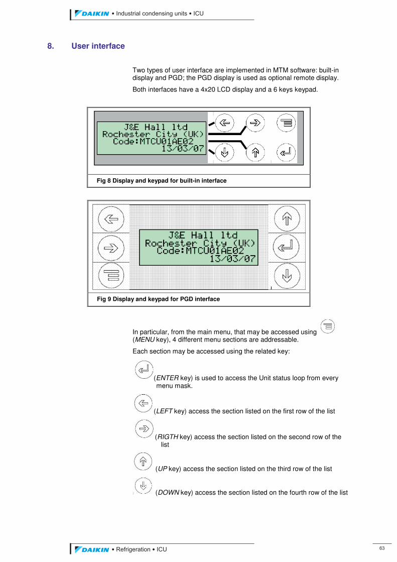
��������� ����������������������
������������������ ��
8. User interface
Two types of user interface are implemented in MTM software: built-in display and PGD; the PGD display is used as optional remote display.
Both interfaces have a 4x20 LCD display and a 6 keys keypad.
Fig 8 Display and keypad for built-in interface
Fig 9 Display and keypad for PGD interface
In particular, from the main menu, that may be accessed using (MENU key), 4 different menu sections are addressable.
Each section may be accessed using the related key:
(ENTER key) is used to access the Unit status loop from every menu mask.
(LEFT key) access the section listed on the first row of the list
(RIGTH key) access the section listed on the second row of the list
(UP key) access the section listed on the third row of the list
(DOWN key) access the section listed on the fourth row of the list
ICU.pdf 71 26/01/2011 11:11:47
��
��������� ����������������������
������������������
In both the programmed interfaces each key is programmed to perform the same action. In addition keys combines have been introduced to improve the usability of the interface. The programmed combine and the related functionalities are described in the following Table 11.
Combine Action
Prog+Up Shows the version mask
Menu+Enter Main menu mask
Left+Down Active alarms
Menu+Enter Enter the Super User password mask from other password mask
Up+Down Reset recycle timers if used in the compressor status mask
Up+Down Reset passwords if pressed in masks different from compressor status masks and if a password is still active
Table 11 Key combines and corresponding action
ICU.pdf 72 26/01/2011 11:11:47
��������� ����������������������
������������������ ��
9. Mask loops
9.1. Interface structure
Masks are organized in different loops respecting parameter types and specificity. In this optic there are loops reserved to the manufacturer or to user or to service and maintenance personnel. Each reserved area could be accessed to view parameters but the changing of them will require a different access level depending on the parameter type. The configured access levels are shown in the following Table 12.
Level Password Validity time
Super User 10101 – 21212 �
Technician 2112 – 9301 240 min
Manager 1002 15 min
Operator 200 15 min
Table 12 Access levels and corresponding passwords
Super User and Technician passwords grant access to all parameter the only difference is the expiration time.
When a password is active, it gives access to all lower levels parameters. It will means that the Super User password and Technician passwords grant the access also to Manager and User parameters whereas the Manager password grants access also to User parameters but not to Technician parameters.
A special loop is present to allow the debugging of the software. Also this loop is password protected and the access is reserved to skilled personnel and programmers. The password to access this loop is “JE”.
9.2. Interface loops surfing
Mask loops are could be flown both vertically and horizontally respecting the categorization shown in the following scheme (into brackets the reference to the corresponding section with the list of masks):
ICU.pdf 73 26/01/2011 11:11:47
��
��������� ����������������������
������������������
Fig 10 Mask loops structure
ICU.pdf 74 26/01/2011 11:11:47
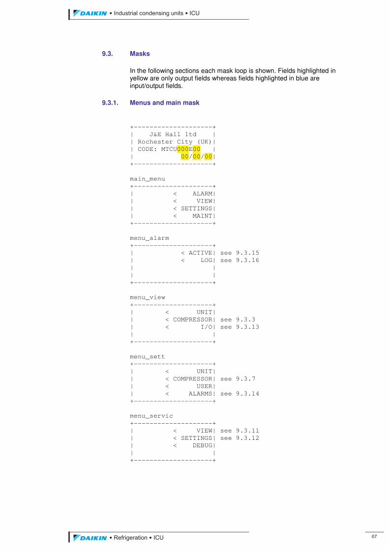
��������� ����������������������
������������������ ��
9.3. Masks In the following sections each mask loop is shown. Fields highlighted in yellow are only output fields whereas fields highlighted in blue are input/output fields.
9.3.1. Menus and main mask
+--------------------+ | J&E Hall ltd | | Rochester City (UK)| | CODE: MTCU000E00 | | 00/00/00| +--------------------+ main_menu +--------------------+ | < ALARM| | < VIEW| | < SETTINGS| | < MAINT| +--------------------+ menu_alarm +--------------------+ | < ACTIVE| see 9.3.15 | < LOG| see 9.3.16 | | | | +--------------------+ menu_view +--------------------+ | < UNIT| | < COMPRESSOR| see 9.3.3 | < I/O| see 9.3.13 | | +--------------------+ menu_sett +--------------------+ | < UNIT| | < COMPRESSOR| see 9.3.7 | < USER| | < ALARMS| see 9.3.14 +--------------------+ menu_servic +--------------------+ | < VIEW| see 9.3.11 | < SETTINGS| see 9.3.12 | < DEBUG| | | +--------------------+
ICU.pdf 75 26/01/2011 11:11:47
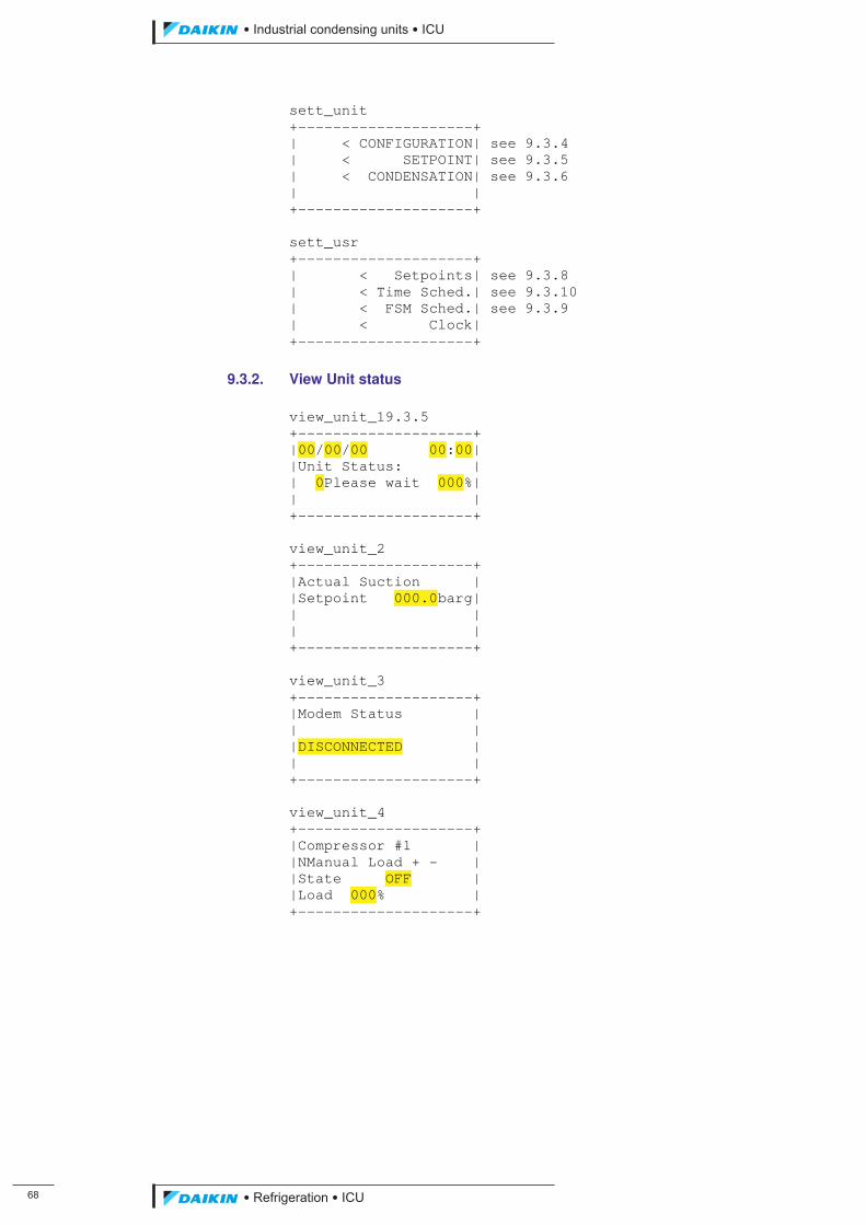
��
��������� ����������������������
������������������
sett_unit +--------------------+ | < CONFIGURATION| see 9.3.4 | < SETPOINT| see 9.3.5 | < CONDENSATION| see 9.3.6 | | +--------------------+ sett_usr +--------------------+ | < Setpoints| see 9.3.8 | < Time Sched.| see 9.3.10 | < FSM Sched.| see 9.3.9 | < Clock| +--------------------+
9.3.2. View Unit status view_unit_19.3.5 +--------------------+ |00/00/00 00:00| |Unit Status: | | 0Please wait 000%| | | +--------------------+ view_unit_2 +--------------------+ |Actual Suction | |Setpoint 000.0barg| | | | | +--------------------+ view_unit_3 +--------------------+ |Modem Status | | | |DISCONNECTED | | | +--------------------+ view_unit_4 +--------------------+ |Compressor #1 | |NManual Load + - | |State OFF | |Load 000% | +--------------------+
ICU.pdf 76 26/01/2011 11:11:47
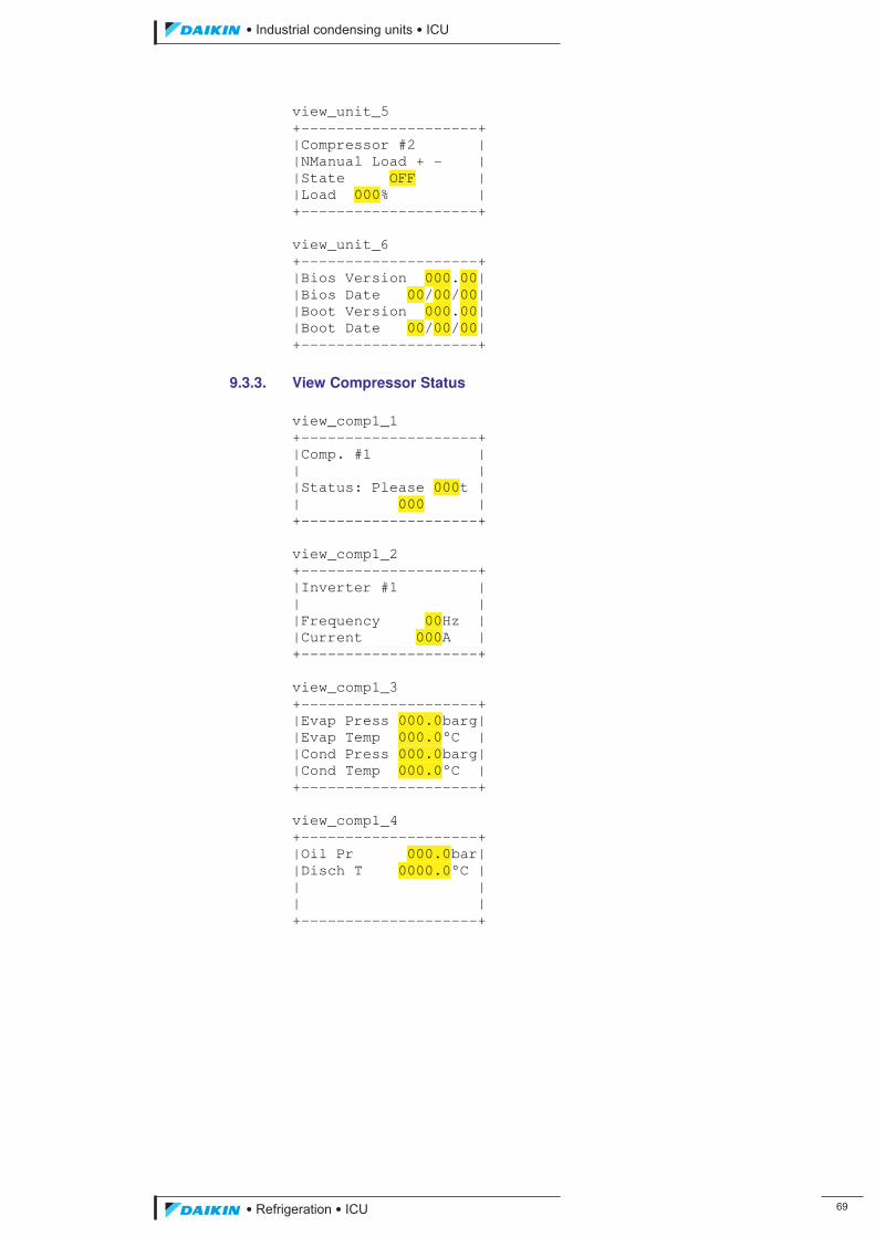
��������� ����������������������
������������������ ��
view_unit_5 +--------------------+ |Compressor #2 | |NManual Load + - | |State OFF | |Load 000% | +--------------------+ view_unit_6 +--------------------+ |Bios Version 000.00| |Bios Date 00/00/00| |Boot Version 000.00| |Boot Date 00/00/00| +--------------------+
9.3.3. View Compressor Status
view_comp1_1 +--------------------+ |Comp. #1 | | | |Status: Please 000t | | 000 | +--------------------+ view_comp1_2 +--------------------+ |Inverter #1 | | | |Frequency 00Hz | |Current 000A | +--------------------+ view_comp1_3 +--------------------+ |Evap Press 000.0barg| |Evap Temp 000.0°C | |Cond Press 000.0barg| |Cond Temp 000.0°C | +--------------------+ view_comp1_4 +--------------------+ |Oil Pr 000.0bar| |Disch T 0000.0°C | | | | | +--------------------+
ICU.pdf 77 26/01/2011 11:11:47
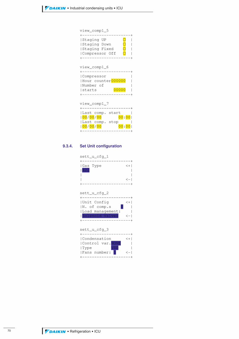
�
��������� ����������������������
������������������
view_comp1_5 +--------------------+ |Staging UP � | |Staging Down � | |Staging Fixed � | |Compressor Off � | +--------------------+ view_comp1_6 +--------------------+ |Compressor | |Hour counter000000 | |Number of | |starts 00000 | +--------------------+ view_comp1_7 +--------------------+ |Last comp. start | |00/00/00 00:00| |Last comp. stop | |00/00/00 00:00| +--------------------+
9.3.4. Set Unit configuration
sett_u_cfg_1 +--------------------+ |Gas Type <+| |R22 | | | | <-| +--------------------+ sett_u_cfg_2 +--------------------+ |Unit Config <+| |N. of comp.s 0 | |Load management: | |Solenoid Valves <-| +--------------------+ sett_u_cfg_3 +--------------------+ |Condensation <+| |Control var.NONE | |Type VSD | |Fans number: 0 <-| +--------------------+
ICU.pdf 78 26/01/2011 11:11:47
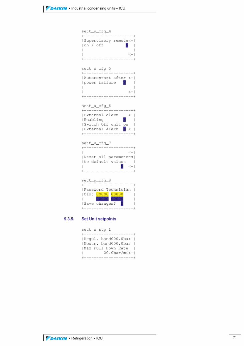
��������� ����������������������
������������������ ��
sett_u_cfg_4 +--------------------+ |Supervisory remote<+| |on / off N | | | | <-| +--------------------+ sett_u_cfg_5 +--------------------+ |Autorestart after <+| |power failure N | | | | <-| +--------------------+ sett_u_cfg_6 +--------------------+ |External alarm <+| |Enabling N | |Switch Off unit on | |External Alarm N <-| +--------------------+ sett_u_cfg_7 +--------------------+ | <+| |Reset all parameters| |to default values | | N <-| +--------------------+ sett_u_cfg_8 +--------------------+ |Password Technician | |Old: 00000 00000 | | 00000 00000 | |Save changes? N | +--------------------+
9.3.5. Set Unit setpoints sett_u_stp_1 +--------------------+ |Regul. band000.0ba<+| |Neutr. band000.0bar | |Max Pull Down Rate | | 00.0bar/mi<-| +--------------------+
ICU.pdf 79 26/01/2011 11:11:47
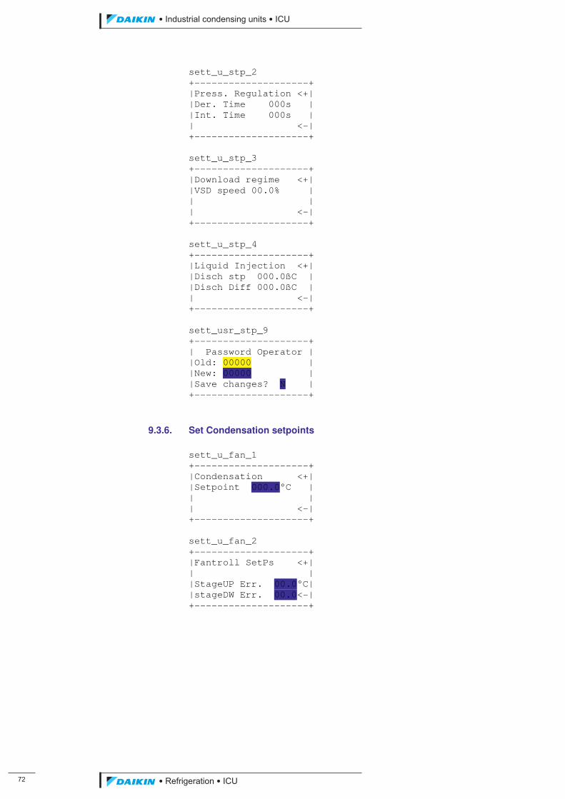
��
��������� ����������������������
������������������
sett_u_stp_2 +--------------------+ |Press. Regulation <+| |Der. Time 000s | |Int. Time 000s | | <-| +--------------------+ sett_u_stp_3 +--------------------+ |Download regime <+| |VSD speed 00.0% | | | | <-| +--------------------+ sett_u_stp_4 +--------------------+ |Liquid Injection <+| |Disch stp 000.0ßC | |Disch Diff 000.0ßC | | <-| +--------------------+ sett_usr_stp_9 +--------------------+ | Password Operator | |Old: 00000 | |New: 00000 | |Save changes? N | +--------------------+
9.3.6. Set Condensation setpoints sett_u_fan_1 +--------------------+ |Condensation <+| |Setpoint 000.0°C | | | | <-| +--------------------+ sett_u_fan_2 +--------------------+ |Fantroll SetPs <+| | | |StageUP Err. 00.0°C| |stageDW Err. 00.0<-| +--------------------+
ICU.pdf 80 26/01/2011 11:11:47
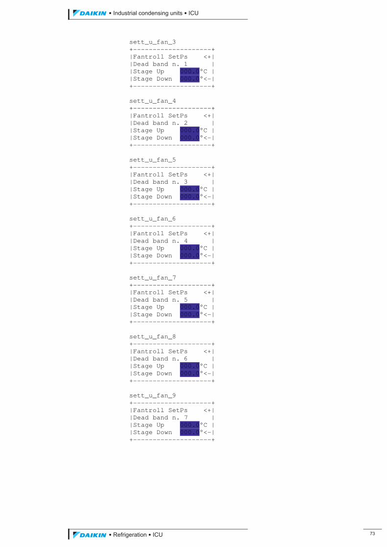
��������� ����������������������
������������������ ��
sett_u_fan_3 +--------------------+ |Fantroll SetPs <+| |Dead band n. 1 | |Stage Up 000.0°C | |Stage Down 000.0°<-| +--------------------+ sett_u_fan_4 +--------------------+ |Fantroll SetPs <+| |Dead band n. 2 | |Stage Up 000.0°C | |Stage Down 000.0°<-| +--------------------+ sett_u_fan_5 +--------------------+ |Fantroll SetPs <+| |Dead band n. 3 | |Stage Up 000.0°C | |Stage Down 000.0°<-| +--------------------+ sett_u_fan_6 +--------------------+ |Fantroll SetPs <+| |Dead band n. 4 | |Stage Up 000.0°C | |Stage Down 000.0°<-| +--------------------+ sett_u_fan_7 +--------------------+ |Fantroll SetPs <+| |Dead band n. 5 | |Stage Up 000.0°C | |Stage Down 000.0°<-| +--------------------+ sett_u_fan_8 +--------------------+ |Fantroll SetPs <+| |Dead band n. 6 | |Stage Up 000.0°C | |Stage Down 000.0°<-| +--------------------+ sett_u_fan_9 +--------------------+ |Fantroll SetPs <+| |Dead band n. 7 | |Stage Up 000.0°C | |Stage Down 000.0°<-| +--------------------+
ICU.pdf 81 26/01/2011 11:11:47
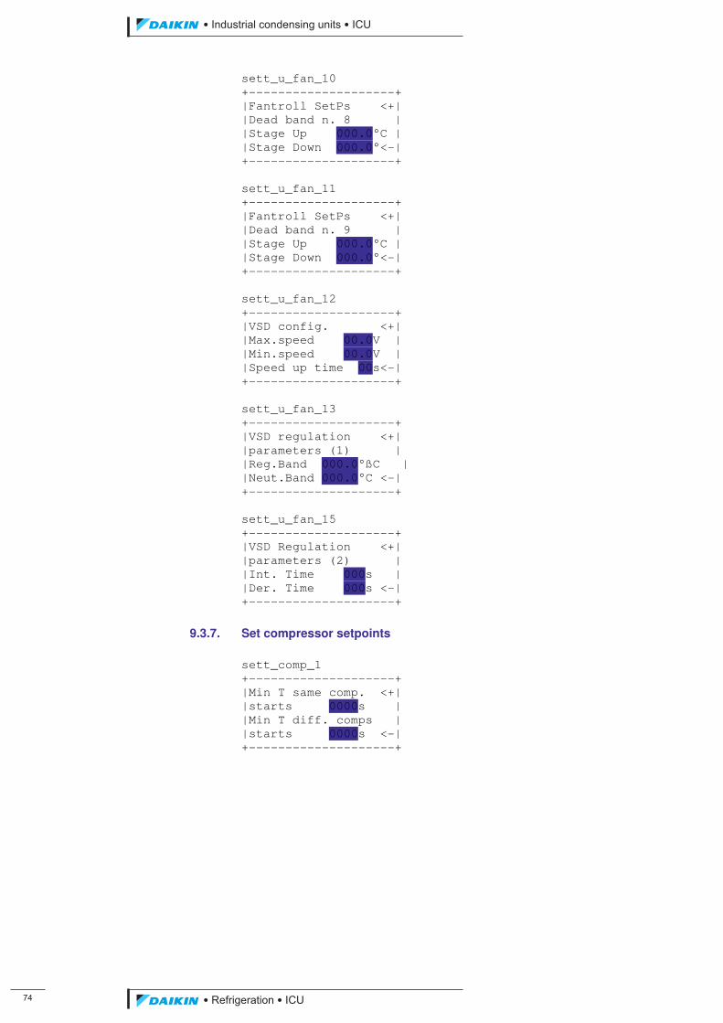
��
��������� ����������������������
������������������
sett_u_fan_10 +--------------------+ |Fantroll SetPs <+| |Dead band n. 8 | |Stage Up 000.0°C | |Stage Down 000.0°<-| +--------------------+ sett_u_fan_11 +--------------------+ |Fantroll SetPs <+| |Dead band n. 9 | |Stage Up 000.0°C | |Stage Down 000.0°<-| +--------------------+ sett_u_fan_12 +--------------------+ |VSD config. <+| |Max.speed 00.0V | |Min.speed 00.0V | |Speed up time 00s<-| +--------------------+ sett_u_fan_13 +--------------------+ |VSD regulation <+| |parameters (1) | |Reg.Band 000.0°ßC | |Neut.Band 000.0°C <-| +--------------------+ sett_u_fan_15 +--------------------+ |VSD Regulation <+| |parameters (2) | |Int. Time 000s | |Der. Time 000s <-| +--------------------+
9.3.7. Set compressor setpoints sett_comp_1 +--------------------+ |Min T same comp. <+| |starts 0000s | |Min T diff. comps | |starts 0000s <-| +--------------------+
ICU.pdf 82 26/01/2011 11:11:47
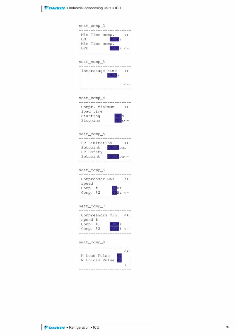
��������� ����������������������
������������������ ��
sett_comp_2 +--------------------+ |Min Time comp. <+| |ON 0000s | |Min Time comp. | |OFF 0000s <-| +--------------------+ sett_comp_3 +--------------------+ |Interstage time <+| | 0000s | | | | <-| +--------------------+ sett_comp_4 +--------------------+ |Compr. minimum <+| |load time | |Starting 000s | |Stopping 000s<-| +--------------------+ sett_comp_5 +--------------------+ |HP Limitation <+| |Setpoint 000.0bar | |HP Safety | |Setpoint 000.0ba<-| +--------------------+ sett_comp_6 +--------------------+ |Compressor MAX <+| |speed | |Comp. #1 00Hz | |Comp. #2 00Hz <-| +--------------------+ sett_comp_7 +--------------------+ |Compressors min. <+| |speed % | |Comp. #1 00.0% | |Comp. #2 00.0% <-| +--------------------+ sett_comp_8 +--------------------+ | <+| |N Load Pulse 00 | |N Unload Pulse 00 | | <-| +--------------------+
ICU.pdf 83 26/01/2011 11:11:47
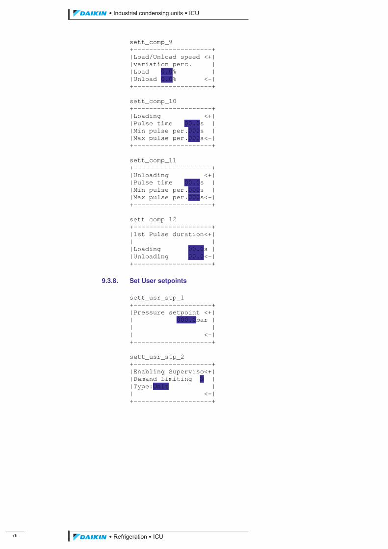
��
��������� ����������������������
������������������
sett_comp_9 +--------------------+ |Load/Unload speed <+| |variation perc. | |Load 0.0% | |Unload 0.0% <-| +--------------------+ sett_comp_10 +--------------------+ |Loading <+| |Pulse time 00.0s | |Min pulse per.000s | |Max pulse per.000s<-| +--------------------+ sett_comp_11 +--------------------+ |Unloading <+| |Pulse time 00.0s | |Min pulse per.000s | |Max pulse per.000s<-| +--------------------+ sett_comp_12 +--------------------+ |1st Pulse duration<+| | | |Loading 00.0s | |Unloading 00.0<-| +--------------------+
9.3.8. Set User setpoints sett_usr_stp_1 +--------------------+ |Pressure setpoint <+| | 000.0bar | | | | <-| +--------------------+ sett_usr_stp_2 +--------------------+ |Enabling Superviso<+| |Demand Limiting N | |Type:Unit | | <-| +--------------------+
ICU.pdf 84 26/01/2011 11:11:47
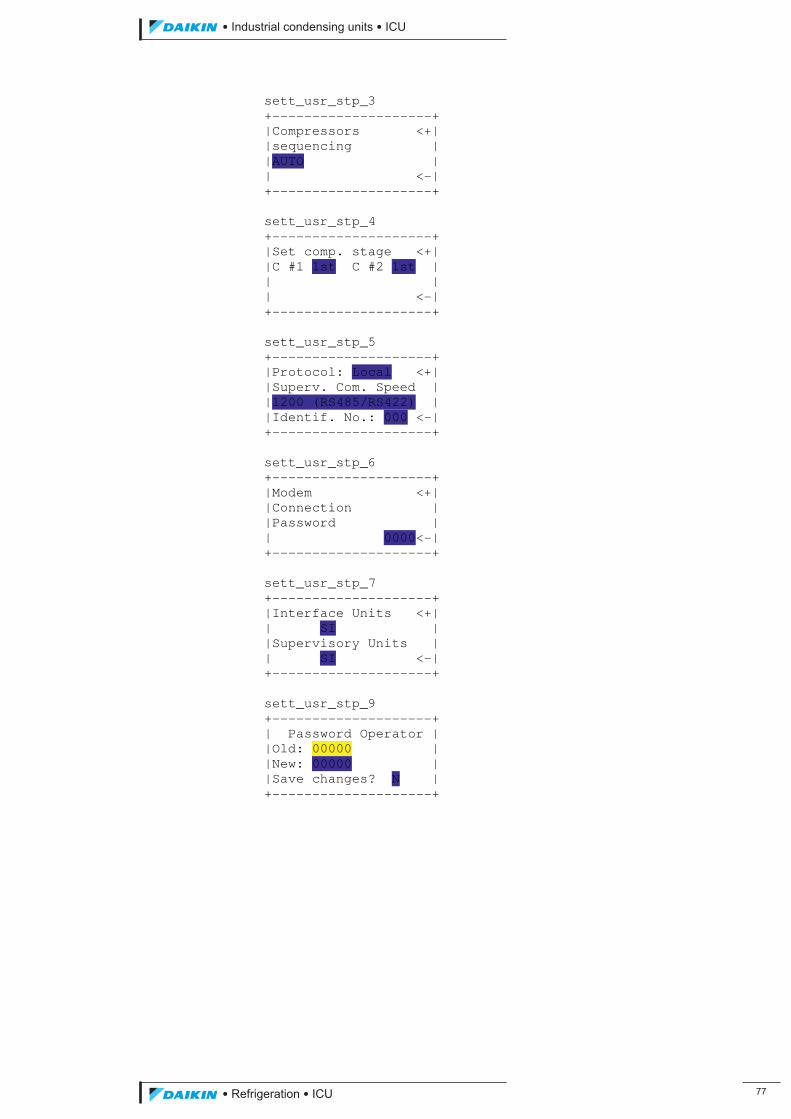
��������� ����������������������
������������������ ��
sett_usr_stp_3 +--------------------+ |Compressors <+| |sequencing | |AUTO | | <-| +--------------------+ sett_usr_stp_4 +--------------------+ |Set comp. stage <+| |C #1 1st C #2 1st | | | | <-| +--------------------+ sett_usr_stp_5 +--------------------+ |Protocol: Local <+| |Superv. Com. Speed | |1200 (RS485/RS422) | |Identif. No.: 000 <-| +--------------------+ sett_usr_stp_6 +--------------------+ |Modem <+| |Connection | |Password | | 0000<-| +--------------------+ sett_usr_stp_7 +--------------------+ |Interface Units <+| | SI | |Supervisory Units | | SI <-| +--------------------+ sett_usr_stp_9 +--------------------+ | Password Operator | |Old: 00000 | |New: 00000 | |Save changes? N | +--------------------+
ICU.pdf 85 26/01/2011 11:11:47
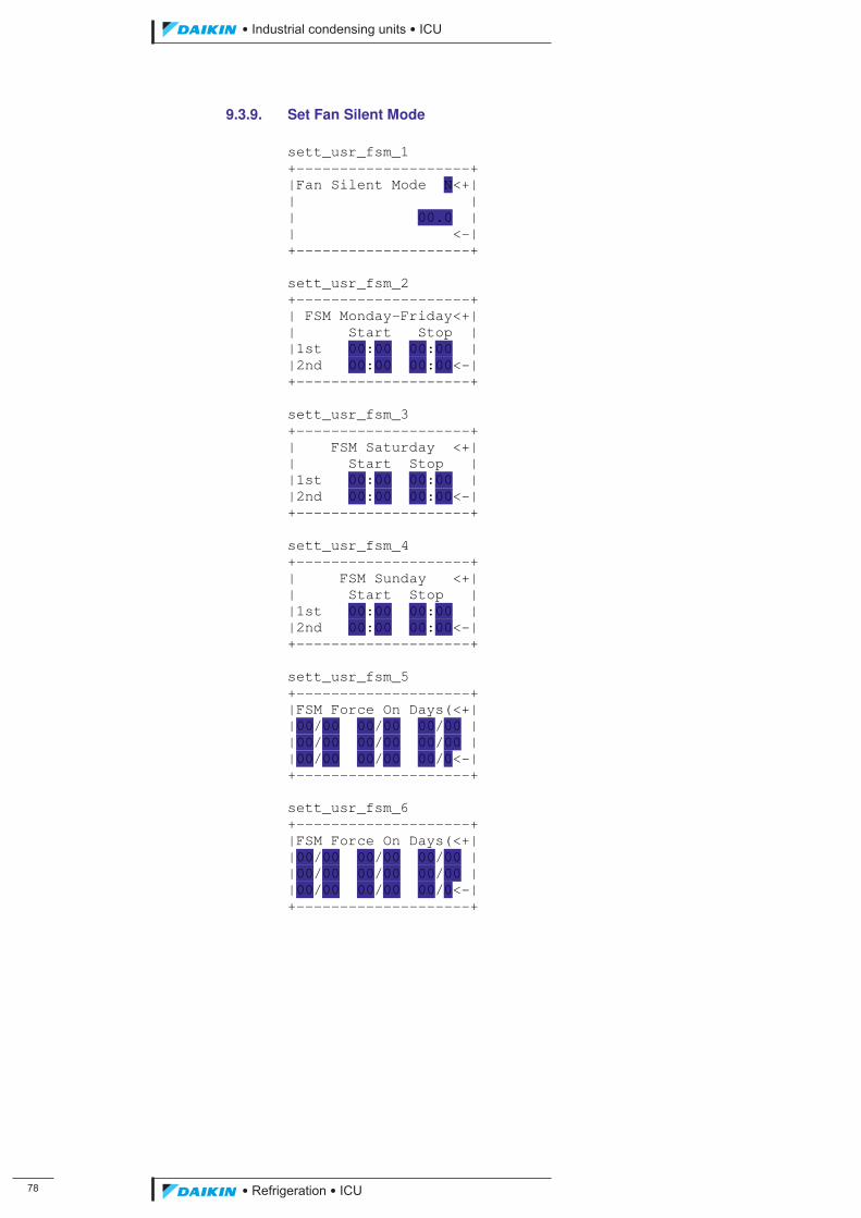
��
��������� ����������������������
������������������
9.3.9. Set Fan Silent Mode sett_usr_fsm_1 +--------------------+ |Fan Silent Mode N<+| | | | 00.0 | | <-| +--------------------+ sett_usr_fsm_2 +--------------------+ | FSM Monday-Friday<+| | Start Stop | |1st 00:00 00:00 | |2nd 00:00 00:00<-| +--------------------+ sett_usr_fsm_3 +--------------------+ | FSM Saturday <+| | Start Stop | |1st 00:00 00:00 | |2nd 00:00 00:00<-| +--------------------+ sett_usr_fsm_4 +--------------------+ | FSM Sunday <+| | Start Stop | |1st 00:00 00:00 | |2nd 00:00 00:00<-| +--------------------+ sett_usr_fsm_5 +--------------------+ |FSM Force On Days(<+| |00/00 00/00 00/00 | |00/00 00/00 00/00 | |00/00 00/00 00/0<-| +--------------------+ sett_usr_fsm_6 +--------------------+ |FSM Force On Days(<+| |00/00 00/00 00/00 | |00/00 00/00 00/00 | |00/00 00/00 00/0<-| +--------------------+
ICU.pdf 86 26/01/2011 11:11:47
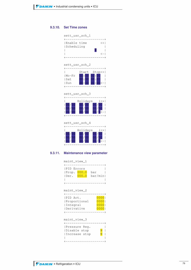
��������� ����������������������
������������������ ��
9.3.10. Set Time zones sett_usr_sch_1 +--------------------+ |Enable time <+| |Scheduling | | N | | <-| +--------------------+ sett_usr_sch_2 +--------------------+ | Start Stop<+| |Mo-Fr 00:00 00:00 | |Sat 00:00 00:00 | |Sun 00:00 00:00<-| +--------------------+ sett_usr_sch_3 +--------------------+ | Holidays (<+| |00/00 00/00 00/00 | |00/00 00/00 00/00 | |00/00 00/00 00/0<-| +--------------------+ sett_usr_sch_4 +--------------------+ | Holidays (<+| |00/00 00/00 00/00 | |00/00 00/00 00/00 | |00/00 00/00 00/0<-| +--------------------+
9.3.11. Maintenance view parameter maint_view_1 +--------------------+ |PID Errors | |Prop. 000.0 bar | |Der. 000.0 bar/min| | | +--------------------+ maint_view_2 +--------------------+ |PID Act. 0000| |Proportional 0000| |Integral 0000| |Derivative 0000| +--------------------+ maint_view_3 +--------------------+ |Pressure Reg. | |Disable stop N | |Increase stop N | | | +--------------------+
ICU.pdf 87 26/01/2011 11:11:47
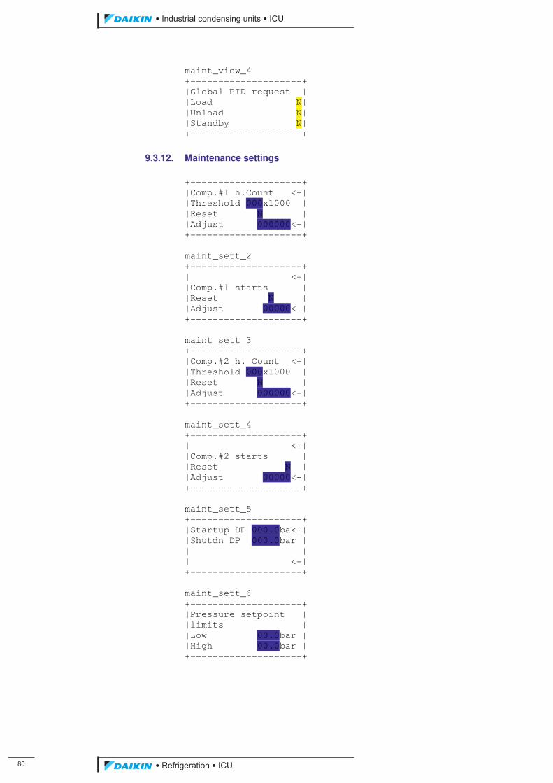
�
��������� ����������������������
������������������
maint_view_4 +--------------------+ |Global PID request | |Load N| |Unload N| |Standby N| +--------------------+
9.3.12. Maintenance settings +--------------------+ |Comp.#1 h.Count <+| |Threshold 000x1000 | |Reset N | |Adjust 000000<-| +--------------------+ maint_sett_2 +--------------------+ | <+| |Comp.#1 starts | |Reset N | |Adjust 00000<-| +--------------------+ maint_sett_3 +--------------------+ |Comp.#2 h. Count <+| |Threshold 000x1000 | |Reset N | |Adjust 000000<-| +--------------------+ maint_sett_4 +--------------------+ | <+| |Comp.#2 starts | |Reset N | |Adjust 00000<-| +--------------------+ maint_sett_5 +--------------------+ |Startup DP 000.0ba<+| |Shutdn DP 000.0bar | | | | <-| +--------------------+ maint_sett_6 +--------------------+ |Pressure setpoint | |limits | |Low 00.0bar | |High 00.0bar | +--------------------+
ICU.pdf 88 26/01/2011 11:11:47
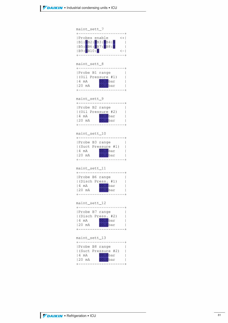
��������� ����������������������
������������������ ��
maint_sett_7 +--------------------+ |Probes enable <+| |B1:NB2:NB3:NB4:N | |B5:NB6:NB7:NB8:N | |B9:NB10:N <-| +--------------------+ maint_sett_8 +--------------------+ |Probe B1 range | |(Oil Pressure #1) | |4 mA 00.0bar | |20 mA 00.0bar | +--------------------+ maint_sett_9 +--------------------+ |Probe B2 range | |(Oil Pressure #2) | |4 mA 00.0bar | |20 mA 00.0bar | +--------------------+ maint_sett_10 +--------------------+ |Probe B3 range | |(Suct Pressure #1) | |4 mA 00.0bar | |20 mA 00.0bar | +--------------------+ maint_sett_11 +--------------------+ |Probe B6 range | |(Disch Press. #1) | |4 mA 00.0bar | |20 mA 00.0bar | +--------------------+ maint_sett_12 +--------------------+ |Probe B7 range | |(Disch Press. #2) | |4 mA 00.0bar | |20 mA 00.0bar | +--------------------+ maint_sett_13 +--------------------+ |Probe B8 range | |(Suct Pressure #2) | |4 mA 00.0bar | |20 mA 00.0bar | +--------------------+
ICU.pdf 89 26/01/2011 11:11:48
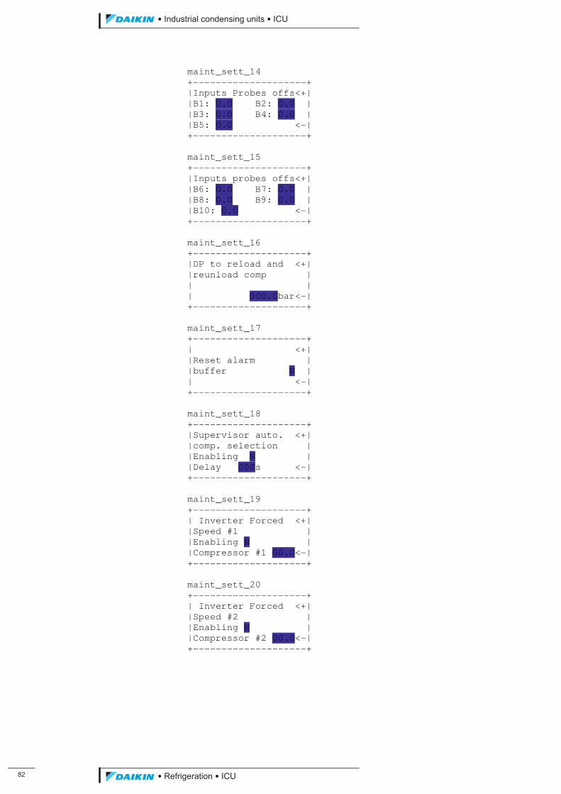
��
��������� ����������������������
������������������
maint_sett_14 +--------------------+ |Inputs Probes offs<+| |B1: 0.0 B2: 0.0 | |B3: 0.0 B4: 0.0 | |B5: 0.0 <-| +--------------------+ maint_sett_15 +--------------------+ |Inputs probes offs<+| |B6: 0.0 B7: 0.0 | |B8: 0.0 B9: 0.0 | |B10: 0.0 <-| +--------------------+ maint_sett_16 +--------------------+ |DP to reload and <+| |reunload comp | | | | 000.0bar<-| +--------------------+ maint_sett_17 +--------------------+ | <+| |Reset alarm | |buffer N | | <-| +--------------------+ maint_sett_18 +--------------------+ |Supervisor auto. <+| |comp. selection | |Enabling N | |Delay 000s <-| +--------------------+ maint_sett_19 +--------------------+ | Inverter Forced <+| |Speed #1 | |Enabling N | |Compressor #1 00.0<-| +--------------------+ maint_sett_20 +--------------------+ | Inverter Forced <+| |Speed #2 | |Enabling N | |Compressor #2 00.0<-| +--------------------+
ICU.pdf 90 26/01/2011 11:11:48
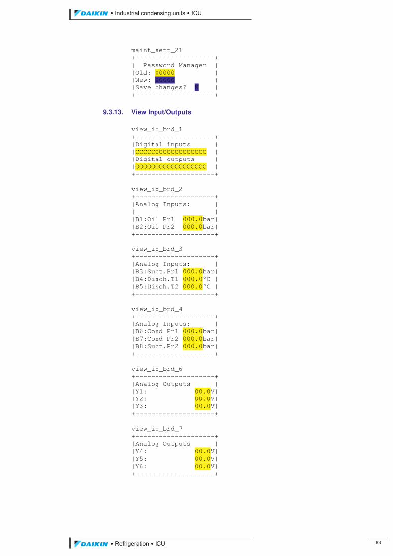
��������� ����������������������
������������������ ��
maint_sett_21 +--------------------+ | Password Manager | |Old: 00000 | |New: 00000 | |Save changes? N | +--------------------+
9.3.13. View Input/Outputs view_io_brd_1 +--------------------+ |Digital inputs | |CCCCCCCCCCCCCCCCCC | |Digital outputs | |OOOOOOOOOOOOOOOOOO | +--------------------+ view_io_brd_2 +--------------------+ |Analog Inputs: | | | |B1:Oil Pr1 000.0bar| |B2:Oil Pr2 000.0bar| +--------------------+ view_io_brd_3 +--------------------+ |Analog Inputs: | |B3:Suct.Pr1 000.0bar| |B4:Disch.T1 000.0°C | |B5:Disch.T2 000.0°C | +--------------------+ view_io_brd_4 +--------------------+ |Analog Inputs: | |B6:Cond Pr1 000.0bar| |B7:Cond Pr2 000.0bar| |B8:Suct.Pr2 000.0bar| +--------------------+ view_io_brd_6 +--------------------+ |Analog Outputs | |Y1: 00.0V| |Y2: 00.0V| |Y3: 00.0V| +--------------------+ view_io_brd_7 +--------------------+ |Analog Outputs | |Y4: 00.0V| |Y5: 00.0V| |Y6: 00.0V| +--------------------+
ICU.pdf 91 26/01/2011 11:11:48
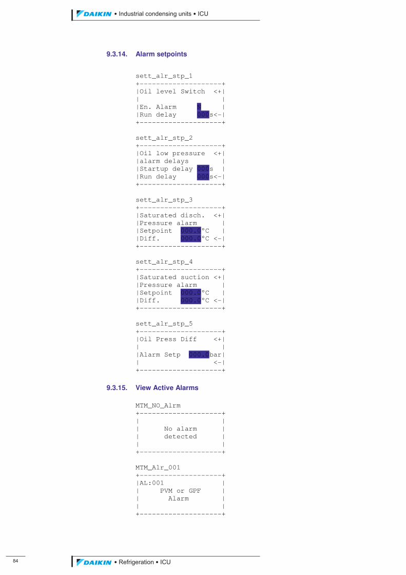
��
��������� ����������������������
������������������
9.3.14. Alarm setpoints
sett_alr_stp_1 +--------------------+ |Oil level Switch <+| | | |En. Alarm N | |Run delay 000s<-| +--------------------+ sett_alr_stp_2 +--------------------+ |Oil low pressure <+| |alarm delays | |Startup delay 000s | |Run delay 000s<-| +--------------------+ sett_alr_stp_3 +--------------------+ |Saturated disch. <+| |Pressure alarm | |Setpoint 000.0°C | |Diff. 000.0°C <-| +--------------------+ sett_alr_stp_4 +--------------------+ |Saturated suction <+| |Pressure alarm | |Setpoint 000.0°C | |Diff. 000.0°C <-| +--------------------+ sett_alr_stp_5 +--------------------+ |Oil Press Diff <+| | | |Alarm Setp 000.0bar| | <-| +--------------------+
9.3.15. View Active Alarms MTM_NO_Alrm +--------------------+ | | | No alarm | | detected | | | +--------------------+ MTM_Alr_001 +--------------------+ |AL:001 | | PVM or GPF | | Alarm | | | +--------------------+
ICU.pdf 92 26/01/2011 11:11:48
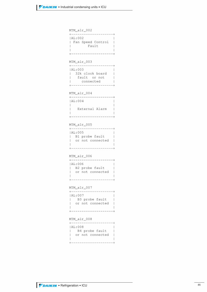
��������� ����������������������
������������������ ��
MTM_alr_002 +--------------------+ |AL:002 | | Fan Speed Control | | Fault | | | +--------------------+ MTM_alr_003 +--------------------+ |AL:003 | | 32k clock board | | fault or not | | connected | +--------------------+ MTM_alr_004 +--------------------+ |AL:004 | | | | External Alarm | | | +--------------------+ MTM_alr_005 +--------------------+ |AL:005 | | B1 probe fault | | or not connected | | | +--------------------+ MTM_alr_006 +--------------------+ |AL:006 | | B2 probe fault | | or not connected | | | +--------------------+ MTM_alr_007 +--------------------+ |AL:007 | | B3 probe fault | | or not connected | | | +--------------------+ MTM_alr_008 +--------------------+ |AL:008 | | B4 probe fault | | or not connected | | | +--------------------+
ICU.pdf 93 26/01/2011 11:11:48
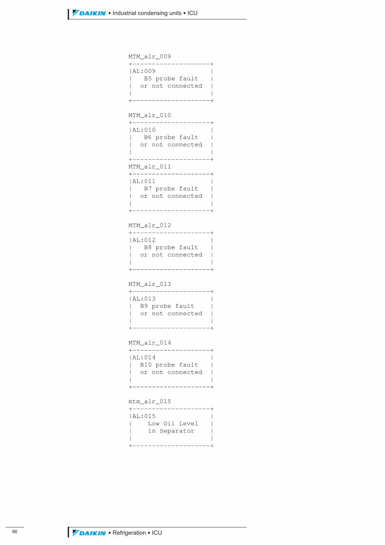
��
��������� ����������������������
������������������
MTM_alr_009 +--------------------+ |AL:009 | | B5 probe fault | | or not connected | | | +--------------------+ MTM_alr_010 +--------------------+ |AL:010 | | B6 probe fault | | or not connected | | | +--------------------+ MTM_alr_011 +--------------------+ |AL:011 | | B7 probe fault | | or not connected | | | +--------------------+ MTM_alr_012 +--------------------+ |AL:012 | | B8 probe fault | | or not connected | | | +--------------------+ MTM_alr_013 +--------------------+ |AL:013 | | B9 probe fault | | or not connected | | | +--------------------+ MTM_alr_014 +--------------------+ |AL:014 | | B10 probe fault | | or not connected | | | +--------------------+ mtm_alr_015 +--------------------+ |AL:015 | | Low Oil Level | | in Separator | | | +--------------------+
ICU.pdf 94 26/01/2011 11:11:48
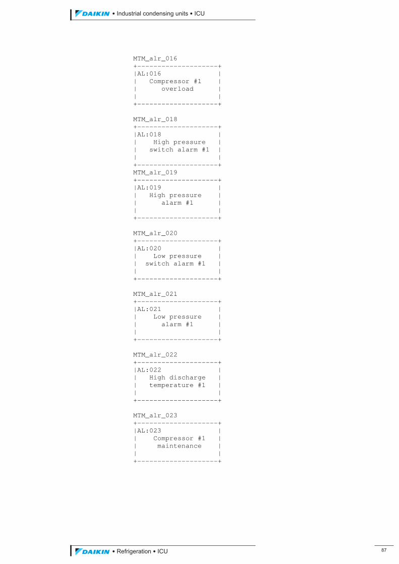
��������� ����������������������
������������������ ��
MTM_alr_016 +--------------------+ |AL:016 | | Compressor #1 | | overload | | | +--------------------+ MTM_alr_018 +--------------------+ |AL:018 | | High pressure | | switch alarm #1 | | | +--------------------+ MTM_alr_019 +--------------------+ |AL:019 | | High pressure | | alarm #1 | | | +--------------------+ MTM_alr_020 +--------------------+ |AL:020 | | Low pressure | | switch alarm #1 | | | +--------------------+ MTM_alr_021 +--------------------+ |AL:021 | | Low pressure | | alarm #1 | | | +--------------------+ MTM_alr_022 +--------------------+ |AL:022 | | High discharge | | temperature #1 | | | +--------------------+ MTM_alr_023 +--------------------+ |AL:023 | | Compressor #1 | | maintenance | | | +--------------------+
ICU.pdf 95 26/01/2011 11:11:48

��
��������� ����������������������
������������������
MTM_alr_024 +--------------------+ |AL:024 | | Transition or | | Solid State | | Alarm #1 | +--------------------+ MTM_alr_025 +--------------------+ |AL:025 | | Low Oil | | Pressure #1 | | | +--------------------+ MTM_alr_026 +--------------------+ |AL:026 | | High Oil | | Pressure difference| | #1 | +--------------------+ MTM_alr_027 +--------------------+ |AL:027 | | Oil Level switch | | Alarm #1 | | | +--------------------+ MTM_alr_028 +--------------------+ |AL:028 | | Compressor #2 | | overload | | | +--------------------+ MTM_alr_030 +--------------------+ |AL:030 | | High pressure | | Switch alarm #2 | | | +--------------------+ MTM_alr_031 +--------------------+ |AL:031 | | High pressure | | alarm #2 | | | +--------------------+
ICU.pdf 96 26/01/2011 11:11:48
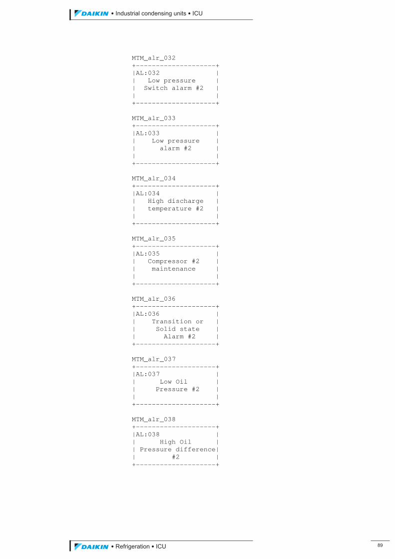
��������� ����������������������
������������������ ��
MTM_alr_032 +--------------------+ |AL:032 | | Low pressure | | Switch alarm #2 | | | +--------------------+ MTM_alr_033 +--------------------+ |AL:033 | | Low pressure | | alarm #2 | | | +--------------------+ MTM_alr_034 +--------------------+ |AL:034 | | High discharge | | temperature #2 | | | +--------------------+ MTM_alr_035 +--------------------+ |AL:035 | | Compressor #2 | | maintenance | | | +--------------------+ MTM_alr_036 +--------------------+ |AL:036 | | Transition or | | Solid state | | Alarm #2 | +--------------------+ MTM_alr_037 +--------------------+ |AL:037 | | Low Oil | | Pressure #2 | | | +--------------------+ MTM_alr_038 +--------------------+ |AL:038 | | High Oil | | Pressure difference| | #2 | +--------------------+
ICU.pdf 97 26/01/2011 11:11:48
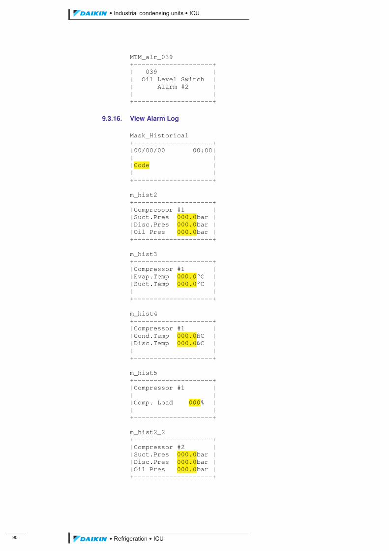
�
��������� ����������������������
������������������
MTM_alr_039 +--------------------+ | 039 | | Oil Level Switch | | Alarm #2 | | | +--------------------+
9.3.16. View Alarm Log Mask_Historical +--------------------+ |00/00/00 00:00| | | |Code | | | +--------------------+ m_hist2 +--------------------+ |Compressor #1 | |Suct.Pres 000.0bar | |Disc.Pres 000.0bar | |Oil Pres 000.0bar | +--------------------+ m_hist3 +--------------------+ |Compressor #1 | |Evap.Temp 000.0°C | |Suct.Temp 000.0°C | | | +--------------------+ m_hist4 +--------------------+ |Compressor #1 | |Cond.Temp 000.0ßC | |Disc.Temp 000.0ßC | | | +--------------------+ m_hist5 +--------------------+ |Compressor #1 | | | |Comp. Load 000% | | | +--------------------+ m_hist2_2 +--------------------+ |Compressor #2 | |Suct.Pres 000.0bar | |Disc.Pres 000.0bar | |Oil Pres 000.0bar | +--------------------+
ICU.pdf 98 26/01/2011 11:11:48
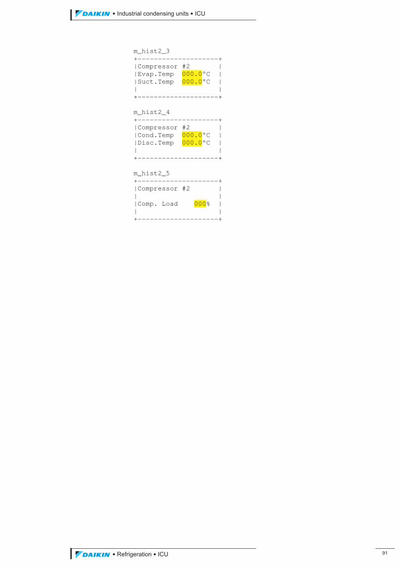
��������� ����������������������
������������������ ��
m_hist2_3 +--------------------+ |Compressor #2 | |Evap.Temp 000.0°C | |Suct.Temp 000.0°C | | | +--------------------+ m_hist2_4 +--------------------+ |Compressor #2 | |Cond.Temp 000.0°C | |Disc.Temp 000.0°C | | | +--------------------+ m_hist2_5 +--------------------+ |Compressor #2 | | | |Comp. Load 000% | | | +--------------------+
ICU.pdf 99 26/01/2011 11:11:48
��
��������� ����������������������
������������������
Safety Electrical wiring must be sized and installed to such a standard as to meet the requirements of the national or local codes pertaining to the area in which the installation is taking place.
The electrical power used in this equipment is at a voltage high enough to endanger life. Before undertaking maintenance or repair procedures, personnel must isolate the equipment from the electrical supply and test to verify that isolation is complete. Precautions must be taken to prevent circuits being inadvertently energised, for example, withdraw the mains fuses or, if this is not practicable, disconnect the equipment from the supply before work commences.
If the supply cannot be disconnected or must remain connected to permit functional testing or fault diagnosis, work should only be undertaken by persons who are aware of the hazard and who have taken adequate precautions to avoid direct contact with dangerous voltages.
If electrical equipment overheats or a fault occurs, it must be disconnected from the supply and allowed to cool. Overheating may damage the insulation system, cables, mouldings, gaskets and seals. The materials used in these components may contain complex organic compounds which, when degraded by heat or electrical action, produce chemical compounds in gaseous, liquid or solid forms. Many of these gaseous and liquid product compounds are highly flammable and toxic.
If it is necessary to extinguish a fire in electrical equipment, follow the advice given in the Regulatory Reform (Fire Safety) Order 2005 available from the Office of Public Sector Information (OPSI). Do not approach the equipment until the fire has been extinguished and the equipment is cool.
ICU.pdf 100 26/01/2011 11:11:48
��������� ����������������������
������������������ ��
1. About this Publication These instructions have been prepared according to the following standards:
BS 4884 : Technical Manuals:
Part 1 : 1992 Specification for Presentation of Essential Information. Part 2 : 1993 Guide to Content. Part 3 : 1993 Guide to Presentation.
BS 4899 : User’s Requirements for Technical Manuals:
Part 1 : 1991 Content. Part 2 : 1992 Presentation.
BS 4899 is based on the principles of BS 4884.
BS 5378 : Part 2 : 1982 Safety Signs.
1.1. Safety Warnings and Symbols
The system of safety warnings and symbols is based on BS 5378 : Part 2 : 1982 Safety Signs and BS 4884 : Technical Manuals : Part 1 : 1992 Specification for Presentation of Essential Information.
� WARNING This denotes an immediate hazard with a high likelihood of personal injury or death if instructions, including recommended precautions, are not followed. There is also a potential risk of damage to the product, process or its surroundings.
� CAUTION This draws attention to instructions which must be complied with to avoid damage to the product, process or its surroundings.
NOTE:
This draws attention to important additional information.
1.2. Units of Measurement
Quantities are expressed in SI units or SI derived units.
1.3. Terminology
Terminology, abbreviations and acronyms are those currently in use throughout the refrigeration and air conditioning industry.
1.4. Ordering Extra Copies
Extra copies of these instructions can be obtained by contacting J & E Hall International. For contact details log onto www.jehall.com
ICU.pdf 101 26/01/2011 11:11:48
��
��������� ����������������������
������������������
2. Care and Protection of the Controller
� CAUTION If welding is to be carried out in the vicinity of the controller or any other items of plant containing semi-conductor devices, for example, transistors and microprocessors, the welding equipment must be adequately earthed adjacent to the point of weld. The controller or other electronic devices must not be positioned between the site where the welding is taking place and the point of earth, or irrevocable damage may be caused to the electronics, with possible consequential damage to the plant.
2.1. Anti-Static Precautions
The electronic cards fitted to the controller are electrostatic sensitive. That is to say, damage to the card or its components can occur as the result of electrostatic discharge from or through personnel. To protect electronic cards and components, precautions against electrostatic hazards must be taken according to BS EN 61340-5-1: 2007. Note the following:
� Persons handling electronic cards must be earthed, in accordance with BS EN 61340-5-1: 2007, to the earth terminal on the controller or other suitable earthing point.
� WARNING The earth bonding device, wrist strap for example, and its application, must conform to BS EN 61340-5-1: 2007. Failure to use the correct earth bonding device in the correct manner can result in death or serious injury if there is accidental contact with hazardous voltages.
� Immediately after removing a card from the controller, place the card in an electrostatic conductive or dissipative envelope. The card should remain in its envelope other than when the card is installed or being worked on.
� When working on a card it must be placed on an earth bonded electrostatic conductive or dissipative mat and the person carrying out the work must be bonded to earth as described above.
� Spare cards must be kept in an electrostatic conductive or dissipative envelope, one card per envelope. Each envelope should be sealed and stored in a cool, dry place well away from strong magnetic sources.
� Never remove or replace an electronic card with the controller power supply turned on.
2.2. Electrical Interference
To avoid problems of electrical interference, all low voltage wiring (transducers, data communications and 24 V dc) must be adequately separated from higher voltage ac wiring (110 V, 240 V, 415 V or higher). A separation of 150 mm is desirable but not always achievable within control panels. Low voltage and higher voltage cables should cross at right-angles.
ICU.pdf 102 26/01/2011 11:11:48
��������� ����������������������
������������������ ��
2.3. Prolonged Storage
If the controller, or the plant of which it forms a part, is not to be installed immediately but held in store, observe the following points:
� The controller should preferably be stored indoors, in a well ventilated, clean, warm and dry environment. If the equipment is stored outside, protection from the elements must be provided; coverings should be selected and arranged to reduce the risk of condensation.
� The controller contains programmed integrated circuits (memory chips) which are sensitive to low temperatures. The controller should not be exposed to ambient temperatures below -10 �C.
ICU.pdf 103 26/01/2011 11:11:48
��
��������� ����������������������
������������������
3. Personnel Permitted to Install, Commission and Maintain the Controller It is essential that only authorised and competent personnel are permitted to undertake installation, commissioning or maintenance work on the controller. A permit to work system should be introduced before commissioning begins, and should be rigorously enforced thereafter.
Any person rendering assistance or under training must be supervised by the authorised competent person who has responsibility for safety.
Personnel must be familiar with the plant’s construction, operation and the hazards involved. All personnel shall make a thorough study of these instructions before undertaking installation, commissioning, maintenance or repair procedures. If in doubt – refer to J & E Hall International.
ICU.pdf 104 26/01/2011 11:11:48
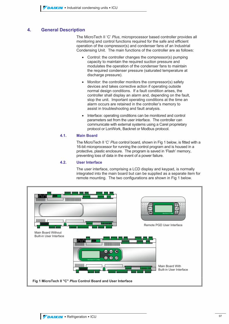
��������� ����������������������
������������������ ��
4. General Description The MicroTech II ‘C’ Plus, microprocessor based controller provides all monitoring and control functions required for the safe and efficient operation of the compressor(s) and condenser fans of an Industrial Condensing Unit. The main functions of the controller are as follows:
� Control: the controller changes the compressor(s) pumping capacity to maintain the required suction pressure and modulates the operation of the condenser fans to maintain the required condenser pressure (saturated temperature at discharge pressure).
� Monitor: the controller monitors the compressor(s) safety devices and takes corrective action if operating outside normal design conditions. If a fault condition arises, the controller shall display an alarm and, depending on the fault, stop the unit. Important operating conditions at the time an alarm occurs are retained in the controller’s memory to assist in troubleshooting and fault analysis.
� Interface: operating conditions can be monitored and control parameters set from the user interface. The controller can communicate with external systems using a Carel proprietary protocol or LonWork, Backnet or Modbus protocol.
4.1. Main Board
The MicroTech II ‘C’ Plus control board, shown in Fig 1 below, is fitted with a 16-bit microprocessor for running the control program and is housed in a protective, plastic enclosure. The program is saved in ‘Flash’ memory, preventing loss of data in the event of a power failure.
4.2. User Interface
The user interface, comprising a LCD display and keypad, is normally integrated into the main board but can be supplied as a separate item for remote mounting. The two configurations are shown in Fig 1 below.
Fig 1 MicroTech II "C" Plus Control Board and User Interface
Remote PGD User Interface
MicroTech II™ PGD
MicroTech II™ "C" Plus
Main Board Without Built-in User Interface
Main Board With Built-in User Interface
ICU.pdf 105 26/01/2011 11:11:49
��
��������� ����������������������
������������������
5. Principles of Control 5.1. Control Definitions
5.1.1. General
Setpoint
The pressure or temperature value that the system is set to control to.
Measured Variable
The pressure or temperature value as measured by a pressure transducer or resistance thermometer and provided to the controller as an analogue signal.
Control Error
The difference between the measured variable and the setpoint.
Delta Pressure (�P) for Start-up
The value above the setpoint at which the compressor is started.
Delta Pressure (�P) for Shut-down
The value below the setpoint at which the compressor is stopped.
5.1.2. Regulation Band
A regulation band is defined and set across the setpoint. If the size of the error is greater or equal to the value of the regulation band, the controller takes the maximum corrective control action. If the error is smaller than the value of the regulation band, the controller takes corrective action scaled down from the maximum value by the ratio of the error to the regulation band, i.e. proportional control. Therefore, the closer the measured value is to the setpoint the smaller the corrective action and vice-versa. If the error is zero, or if the scaled corrective action is smaller than the minimum possible corrective action, no action is taken.
A large regulation band achieves stable control, however, little corrective action is taken for relatively large errors, hence the control response is slow. A large regulation band also permits a large steady state error to exist with no corrective action taking place. Reducing the regulation band reduces steady state error, but control can become unstable as relatively small deviations from the setpoint result in a large corrective action being taken.
5.1.3. Neutral Band
A neutral band is defined and set across the setpoint. If the measured value is within the limits of the neutral band, the controller takes no further corrective control action. The neutral band prevents the controller from taking small corrective actions when the measured value is close to the setpoint.
5.1.4. Integral Action Time
Steady state errors can practically be eliminated whilst achieving stable control by introducing an integral term into the control action.
Integral control integrates error with respect to time, that is, a small fraction of the error is added to a running total at each control assessment. The size of the fraction is determined by the chosen integral action-time, the greater the integral action-time the smaller the fraction. For example, halving the integral action time from the default setting would halve the time taken to generate a load pulse from a small steady state error.
ICU.pdf 106 26/01/2011 11:11:49
��������� ����������������������
������������������ ��
In practical terms, integral control causes control action to be taken when small errors exist over periods of time, even though these errors may be too small for significant action to be taken by proportional control alone. If integral action time is too short, hunting around the setpoint occurs.
Setting integral action time to its maximum value reduces integral action to such an extent that it has virtually no influence on control. Integral control may be also disabled by setting integral action time to zero.
5.1.5. Derivative Action Time
Derivative control looks at the rate of change of error. If the measured variable is moving away from the setpoint the derivative term increases the amount of corrective control action. If the measured variable is moving towards the setpoint the derivative term decreases the amount of corrective action or even applies the opposite control action. Derivative control therefore acts to return the measured variable as quickly as possible towards the setpoint in cases of rapidly applied or fluctuating loads, and also aids stability of the control system by opposing overshoot.
Increasing derivative action time increases the derivative action effect. Decreasing derivative action time reduces the effect; a zero value disables derivative control completely although this is not normally recommended.
5.1.6. PID Control Set-up
By varying the size of the proportional band, integral action time and derivative action time, it is possible to tune the controller to produce different control characteristics, say for a fast response to load changes, or for very close setpoint control. The value for each variable can only be arrived at by exposing the controller to system fluctuations under actual site conditions and modifying each term until the desired response is achieved.
5.2. Unit Enabling
The following inputs and conditions can Enable / Disable the unit, thus determining whether the unit is ON:
� Keypad: a key on the keypad is used to enable the unit at its first start-up and in case of power loss (setting dependent).
� Local Switch: when the digital input ‘Unit ON/OFF’ is opened the unit will be in the ‘OFF Local Switch’ status; when the digital input closes the unit shall either be ON or ‘OFF Remote Switch’ depending on the status of the digital input ‘Remote ON/OFF’.
� Remote Switch: when the local switch is ON and the ‘Remote ON/OFF’ digital input is closed the unit will be ON, whereas if the ‘Remote ON/OFF’ digital input is open the Unit will be ‘OFF Remote Switch’.
� Time Schedule: with time scheduling enabled, the controller can be programmed to start and stop the unit at specific times of the day and on specific dates.
� Network: the controller can be configured to respond to BAS or Remote Monitoring Systems ON/OFF signals through a serial line connection which sets the unit in the ‘Rem. Comm. OFF’ status. The suction pressure setpoint value can be modified via the serial connection.
� Configuration: for each compressor to run its capacity control setting must be set to MANUAL or AUTO, not OFF. NOTE: all conditions must be met for the unit to be ON.
ICU.pdf 107 26/01/2011 11:11:49
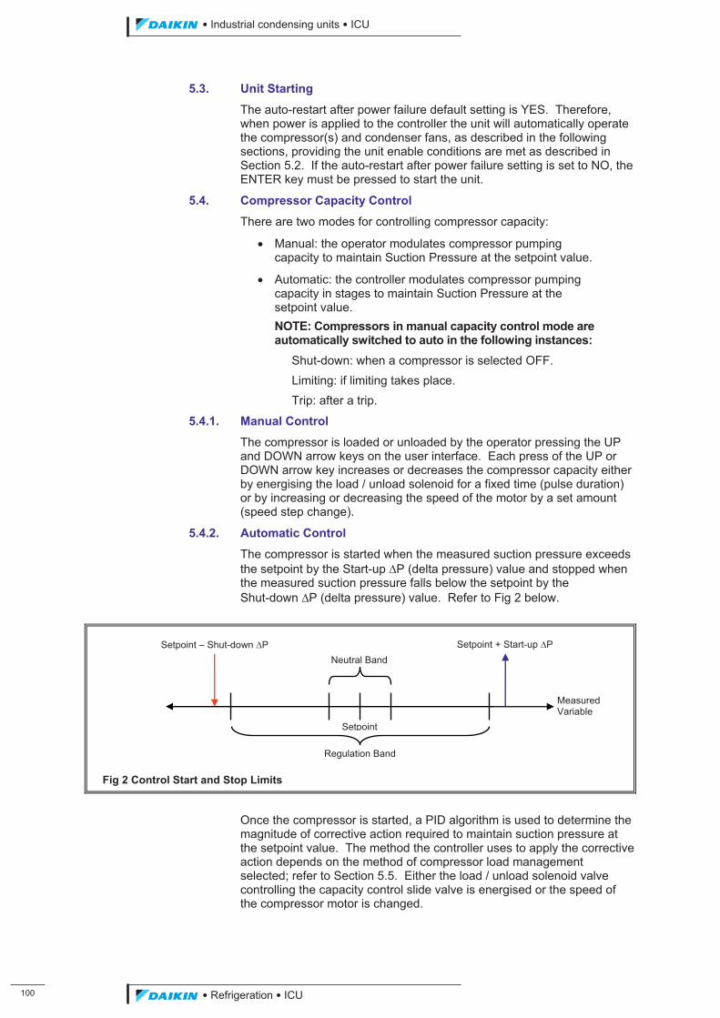
�
��������� ����������������������
������������������
5.3. Unit Starting
The auto-restart after power failure default setting is YES. Therefore, when power is applied to the controller the unit will automatically operate the compressor(s) and condenser fans, as described in the following sections, providing the unit enable conditions are met as described in Section 5.2. If the auto-restart after power failure setting is set to NO, the ENTER key must be pressed to start the unit.
5.4. Compressor Capacity Control
There are two modes for controlling compressor capacity:
� Manual: the operator modulates compressor pumping capacity to maintain Suction Pressure at the setpoint value.
� Automatic: the controller modulates compressor pumping capacity in stages to maintain Suction Pressure at the setpoint value. NOTE: Compressors in manual capacity control mode are automatically switched to auto in the following instances:
Shut-down: when a compressor is selected OFF. Limiting: if limiting takes place. Trip: after a trip.
5.4.1. Manual Control
The compressor is loaded or unloaded by the operator pressing the UP and DOWN arrow keys on the user interface. Each press of the UP or DOWN arrow key increases or decreases the compressor capacity either by energising the load / unload solenoid for a fixed time (pulse duration) or by increasing or decreasing the speed of the motor by a set amount (speed step change).
5.4.2. Automatic Control
The compressor is started when the measured suction pressure exceeds the setpoint by the Start-up �P (delta pressure) value and stopped when the measured suction pressure falls below the setpoint by the Shut-down �P (delta pressure) value. Refer to Fig 2 below.
Fig 2 Control Start and Stop Limits
Once the compressor is started, a PID algorithm is used to determine the magnitude of corrective action required to maintain suction pressure at the setpoint value. The method the controller uses to apply the corrective action depends on the method of compressor load management selected; refer to Section 5.5. Either the load / unload solenoid valve controlling the capacity control slide valve is energised or the speed of the compressor motor is changed.
Neutral Band
Regulation Band
Setpoint
Setpoint – Shut-down �P Setpoint + Start-up �P
Measured Variable
ICU.pdf 108 26/01/2011 11:11:49
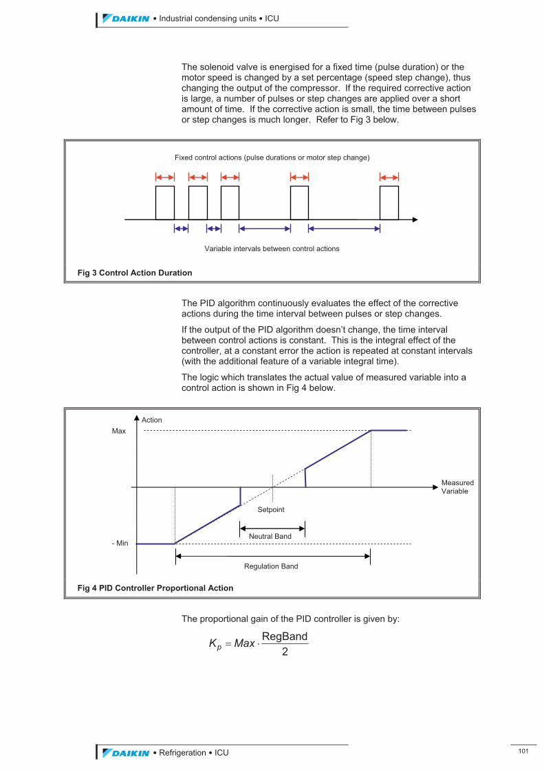
��������� ����������������������
������������������ � �
The solenoid valve is energised for a fixed time (pulse duration) or the motor speed is changed by a set percentage (speed step change), thus changing the output of the compressor. If the required corrective action is large, a number of pulses or step changes are applied over a short amount of time. If the corrective action is small, the time between pulses or step changes is much longer. Refer to Fig 3 below.
Fig 3 Control Action Duration
The PID algorithm continuously evaluates the effect of the corrective actions during the time interval between pulses or step changes.
If the output of the PID algorithm doesn’t change, the time interval between control actions is constant. This is the integral effect of the controller, at a constant error the action is repeated at constant intervals (with the additional feature of a variable integral time).
The logic which translates the actual value of measured variable into a control action is shown in Fig 4 below.
Fig 4 PID Controller Proportional Action
The proportional gain of the PID controller is given by:
2RegBand�� MaxKp
Variable intervals between control actions
Fixed control actions (pulse durations or motor step change)
Max
- Min
Setpoint
Neutral Band
Measured Variable
Action
Regulation Band
ICU.pdf 109 26/01/2011 11:11:49
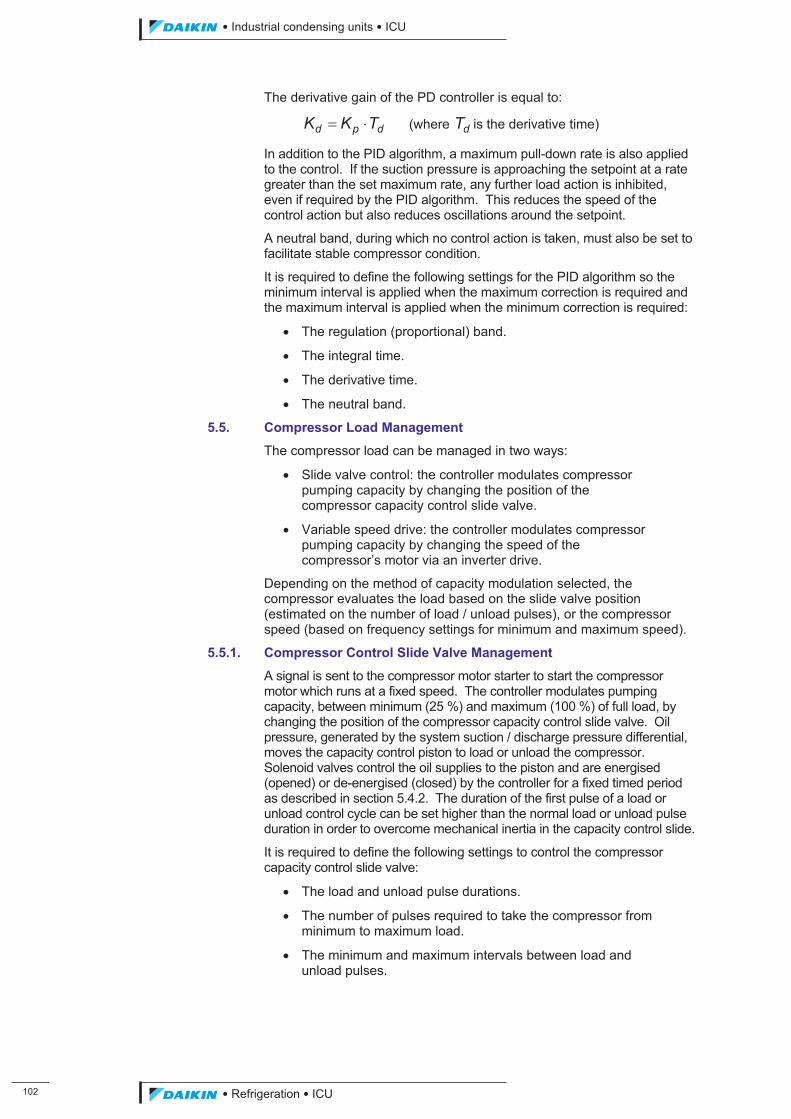
� �
��������� ����������������������
������������������
The derivative gain of the PD controller is equal to:
dpd TKK �� (where dT is the derivative time)
In addition to the PID algorithm, a maximum pull-down rate is also applied to the control. If the suction pressure is approaching the setpoint at a rate greater than the set maximum rate, any further load action is inhibited, even if required by the PID algorithm. This reduces the speed of the control action but also reduces oscillations around the setpoint.
A neutral band, during which no control action is taken, must also be set to facilitate stable compressor condition.
It is required to define the following settings for the PID algorithm so the minimum interval is applied when the maximum correction is required and the maximum interval is applied when the minimum correction is required:
� The regulation (proportional) band.
� The integral time.
� The derivative time.
� The neutral band.
5.5. Compressor Load Management
The compressor load can be managed in two ways:
� Slide valve control: the controller modulates compressor pumping capacity by changing the position of the compressor capacity control slide valve.
� Variable speed drive: the controller modulates compressor pumping capacity by changing the speed of the compressor’s motor via an inverter drive.
Depending on the method of capacity modulation selected, the compressor evaluates the load based on the slide valve position (estimated on the number of load / unload pulses), or the compressor speed (based on frequency settings for minimum and maximum speed).
5.5.1. Compressor Control Slide Valve Management
A signal is sent to the compressor motor starter to start the compressor motor which runs at a fixed speed. The controller modulates pumping capacity, between minimum (25 %) and maximum (100 %) of full load, by changing the position of the compressor capacity control slide valve. Oil pressure, generated by the system suction / discharge pressure differential, moves the capacity control piston to load or unload the compressor. Solenoid valves control the oil supplies to the piston and are energised (opened) or de-energised (closed) by the controller for a fixed timed period as described in section 5.4.2. The duration of the first pulse of a load or unload control cycle can be set higher than the normal load or unload pulse duration in order to overcome mechanical inertia in the capacity control slide.
It is required to define the following settings to control the compressor capacity control slide valve:
� The load and unload pulse durations.
� The number of pulses required to take the compressor from minimum to maximum load.
� The minimum and maximum intervals between load and unload pulses.
ICU.pdf 110 26/01/2011 11:11:49
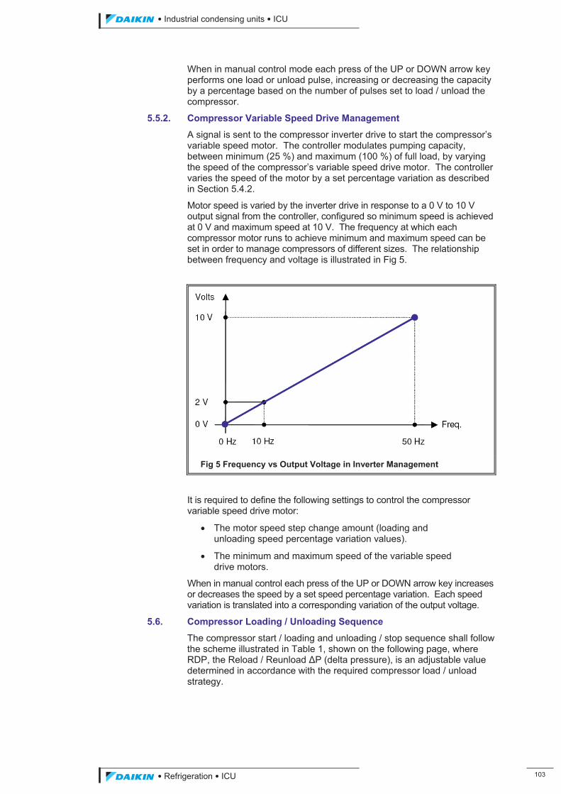
��������� ����������������������
������������������ � �
When in manual control mode each press of the UP or DOWN arrow key performs one load or unload pulse, increasing or decreasing the capacity by a percentage based on the number of pulses set to load / unload the compressor.
5.5.2. Compressor Variable Speed Drive Management
A signal is sent to the compressor inverter drive to start the compressor’s variable speed motor. The controller modulates pumping capacity, between minimum (25 %) and maximum (100 %) of full load, by varying the speed of the compressor’s variable speed drive motor. The controller varies the speed of the motor by a set percentage variation as described in Section 5.4.2.
Motor speed is varied by the inverter drive in response to a 0 V to 10 V output signal from the controller, configured so minimum speed is achieved at 0 V and maximum speed at 10 V. The frequency at which each compressor motor runs to achieve minimum and maximum speed can be set in order to manage compressors of different sizes. The relationship between frequency and voltage is illustrated in Fig 5.
Fig 5 Frequency vs Output Voltage in Inverter Management
It is required to define the following settings to control the compressor variable speed drive motor:
� The motor speed step change amount (loading and unloading speed percentage variation values).
� The minimum and maximum speed of the variable speed drive motors.
When in manual control each press of the UP or DOWN arrow key increases or decreases the speed by a set speed percentage variation. Each speed variation is translated into a corresponding variation of the output voltage.
5.6. Compressor Loading / Unloading Sequence
The compressor start / loading and unloading / stop sequence shall follow the scheme illustrated in Table 1, shown on the following page, where RDP, the Reload / Reunload #P (delta pressure), is an adjustable value determined in accordance with the required compressor load / unload strategy.
ICU.pdf 111 26/01/2011 11:11:49
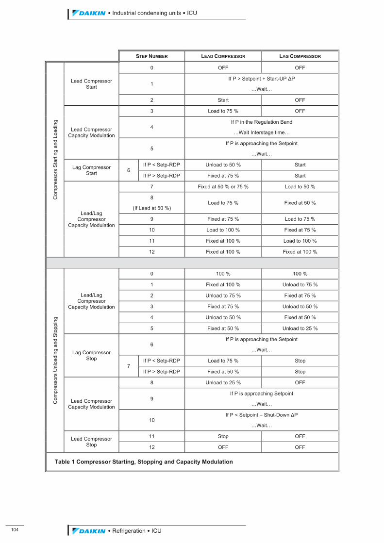
� �
��������� ����������������������
������������������
STEP NUMBER LEAD COMPRESSOR LAG COMPRESSOR C
ompr
esso
rs S
tarti
ng a
nd L
oadi
ng
Lead Compressor Start
0 OFF OFF
1 If P > Setpoint + Start-UP #P
…Wait…
2 Start OFF
Lead Compressor Capacity Modulation
3 Load to 75 % OFF
4 If P in the Regulation Band
…Wait Interstage time…
5 If P is approaching the Setpoint
…Wait…
Lag Compressor Start 6
If P < Setp-RDP Unload to 50 % Start
If P > Setp-RDP Fixed at 75 % Start
Lead/Lag Compressor
Capacity Modulation
7 Fixed at 50 % or 75 % Load to 50 %
8
(If Lead at 50 %) Load to 75 % Fixed at 50 %
9 Fixed at 75 % Load to 75 %
10 Load to 100 % Fixed at 75 %
11 Fixed at 100 % Load to 100 %
12 Fixed at 100 % Fixed at 100 %
Com
pres
sors
Unl
oadi
ng a
nd S
topp
ing
Lead/Lag Compressor
Capacity Modulation
0 100 % 100 %
1 Fixed at 100 % Unload to 75 %
2 Unload to 75 % Fixed at 75 %
3 Fixed at 75 % Unload to 50 %
4 Unload to 50 % Fixed at 50 %
5 Fixed at 50 % Unload to 25 %
Lag Compressor Stop
6 If P is approaching the Setpoint
…Wait…
7 If P < Setp-RDP Load to 75 % Stop
If P > Setp-RDP Fixed at 50 % Stop
Lead Compressor Capacity Modulation
8 Unload to 25 % OFF
9 If P is approaching Setpoint
…Wait…
10 If P < Setpoint – Shut-Down #P
…Wait…
Lead Compressor Stop
11 Stop OFF
12 OFF OFF
Table 1 Compressor Starting, Stopping and Capacity Modulation
ICU.pdf 112 26/01/2011 11:11:49
��������� ����������������������
������������������ � �
5.7. Compressor Timing
In order for a compressor to operate efficiently and to avoid unnecessary cycling the following adjustable timing conditions must be met:
� Minimum time between starts of the same compressor (start to start timer): the minimum time between two starts of the same compressor must have elapsed.
� Minimum time between starts of different compressors (start to start timer): the minimum time between starts of the two different compressors must have elapsed.
� Minimum time compressor ON (minimum time the compressor will run - start to stop timer): the compressor will not stop (unless an alarm occurs) until the timer has expired.
� Minimum Time Compressor OFF (minimum time the compressor is stopped - stop to start timer): the compressor is not permitted to start / re-start until the timer has expired.
� Time compressor held at minimum load when starting (time the compressor is held at minimum load when it is started): the compressor load is not increased until the timer has expired.
� Time compressor held at minimum load when stopping (time the compressor is held at minimum load before it is stopped): the compressor is not completely stopped until the timer has expired.
The controller can also be programmed so the compressors start and stop at specific times of the day or on specific dates.
5.8. Compressor Sequencing
Compressor sequencing can be set to either Manual or Automatic. With manual sequencing selected either compressor #1 or compressor #2 can be set to operate as the lead compressor. With automatic sequencing selected sequencing is based on the number of starts, as recorded in the controller memory, with the compressor with the least number of starts being selected as the lead compressor. The number of starts can be reset to zero, or to a required value, within the maintenance settings.
NOTE: In order for compressor sequencing to operate, both compressors’ ON / OFF digital inputs must be switched to ON (ID1 and ID2 closed).
A facility can also be enabled to allow compressor selection to be made via a remote communication network, including provision of a delay preventing the compressor from being selected until the timer has expired.
5.9. Compressor Limiting
There is the facility to limit the output of the compressor which can prevent the system operating outside the design parameters or chosen limits, and can also allow the plant to keep running under difficult conditions rather than tripping on a fault. Supervisor limiting can also be enabled, allowing limiting to be applied remotely using the communication network. Limiting can be set to be applied to either the unit (both compressors) or a circuit (single compressor).
5.9.1. Discharge Pressure Limiting
Compressor loading is inhibited if the discharge pressure exceeds the adjustable high pressure limitation setpoint. Any further loading is inhibited, and if applied when the compressor is not running, prevents the compressor from starting.
ICU.pdf 113 26/01/2011 11:11:49
� �
��������� ����������������������
������������������
The compressor is unloaded if discharge pressure exceeds the high adjustable high pressure safety setpoint. Unloading continues all the time the signal is applied (contacts closed).
5.9.2. Inverter Forced Speed Limiting
The inverter speed of either or both compressors can be forced to operate at a fixed speed, adjustable between 25 % and 99.9 %.
NOTE: While compressor limiting or load inhibit or force unload conditions exist, the controller prevents further loading or unloads the compressor even though the PID algorithm may be calling for duty.
5.10. Compressor Protection – Pressure Ratio
To protect compressors against loss of lubrication, the compressor pressure ratio is continuously monitored. A minimum value is set for both minimum and maximum compressor loads with a linear interpolation between the two values being applied during intermediate compressor loads.
The low pressure ratio alarm is initiated if the pressure ratio remains below the minimum value at the rated compressor capacity for a certain time (set by manufacturer).
During start up with the compressor unloaded, loading will not be enabled until the pressure ratio exceeds a set value (default equal to 2).
5.11. Compressor Protection – Oil High Level Switch
The compressor is not permitted to start if the oil level switch contacts are open and is disabled until the contacts closes. This condition is ignored when the compressor is running.
5.12. Unit Stopping
The unit can be stopped by removing any one of the unit enable conditions, as described in Section 5.2. When the compressor is required to stop, the controller follows the unload sequence shown previously in Table 1. Once stopped the recycle time begins, preventing the compressor from starting until the required time period between compressor starts has expired.
5.13. Condenser Pressure Control
The controller modulates the condenser pressure by controlling the operation of the condenser fans, the number of which is set during configuration – either 4, 6, 8 or 10.
NOTE: For units provided with 10 condenser fans set the number of fans to 9 (this is the maximum number that the software can accept).
Condenser pressure can be managed in two ways:
� Pressure: the controller operates the condenser fans to maintain condensing saturated temperature (saturated temperature at discharge pressure) at the target setpoint.
� Pressure Ratio: the controller operates the condenser fans to maintain the ratio between the condensing saturated temperature (saturated temperature at discharge pressure) and the evaporating saturated temperature (saturated temperature at suction pressure) above a target setpoint.
Four control logic options are available for operating the condenser fans and are described in the following sections:
ICU.pdf 114 26/01/2011 11:11:49
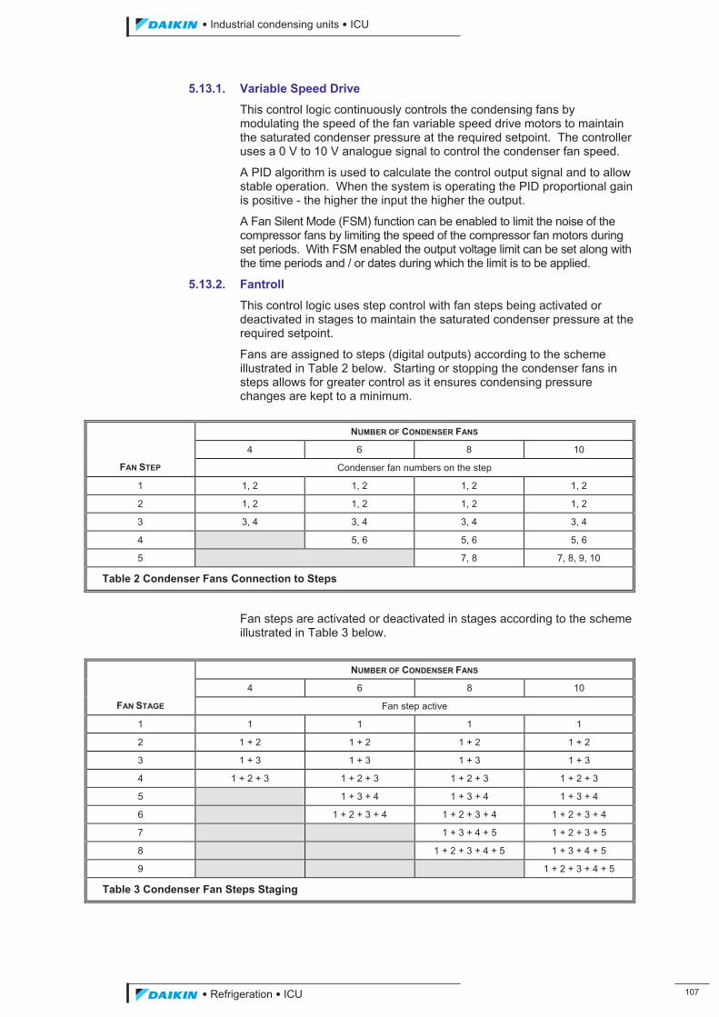
��������� ����������������������
������������������ � �
5.13.1. Variable Speed Drive
This control logic continuously controls the condensing fans by modulating the speed of the fan variable speed drive motors to maintain the saturated condenser pressure at the required setpoint. The controller uses a 0 V to 10 V analogue signal to control the condenser fan speed.
A PID algorithm is used to calculate the control output signal and to allow stable operation. When the system is operating the PID proportional gain is positive - the higher the input the higher the output.
A Fan Silent Mode (FSM) function can be enabled to limit the noise of the compressor fans by limiting the speed of the compressor fan motors during set periods. With FSM enabled the output voltage limit can be set along with the time periods and / or dates during which the limit is to be applied.
5.13.2. Fantroll
This control logic uses step control with fan steps being activated or deactivated in stages to maintain the saturated condenser pressure at the required setpoint.
Fans are assigned to steps (digital outputs) according to the scheme illustrated in Table 2 below. Starting or stopping the condenser fans in steps allows for greater control as it ensures condensing pressure changes are kept to a minimum.
Fan steps are activated or deactivated in stages according to the scheme illustrated in Table 3 below.
FAN STAGE
NUMBER OF CONDENSER FANS
4 6 8 10
Fan step active
1 1 1 1 1
2 1 + 2 1 + 2 1 + 2 1 + 2
3 1 + 3 1 + 3 1 + 3 1 + 3
4 1 + 2 + 3 1 + 2 + 3 1 + 2 + 3 1 + 2 + 3
5 1 + 3 + 4 1 + 3 + 4 1 + 3 + 4
6 1 + 2 + 3 + 4 1 + 2 + 3 + 4 1 + 2 + 3 + 4
7 1 + 3 + 4 + 5 1 + 2 + 3 + 5
8 1 + 2 + 3 + 4 + 5 1 + 3 + 4 + 5
9 1 + 2 + 3 + 4 + 5
Table 3 Condenser Fan Steps Staging
FAN STEP
NUMBER OF CONDENSER FANS
4 6 8 10
Condenser fan numbers on the step
1 1, 2 1, 2 1, 2 1, 2
2 1, 2 1, 2 1, 2 1, 2
3 3, 4 3, 4 3, 4 3, 4
4 5, 6 5, 6 5, 6
5 7, 8 7, 8, 9, 10
Table 2 Condenser Fans Connection to Steps
ICU.pdf 115 26/01/2011 11:11:49
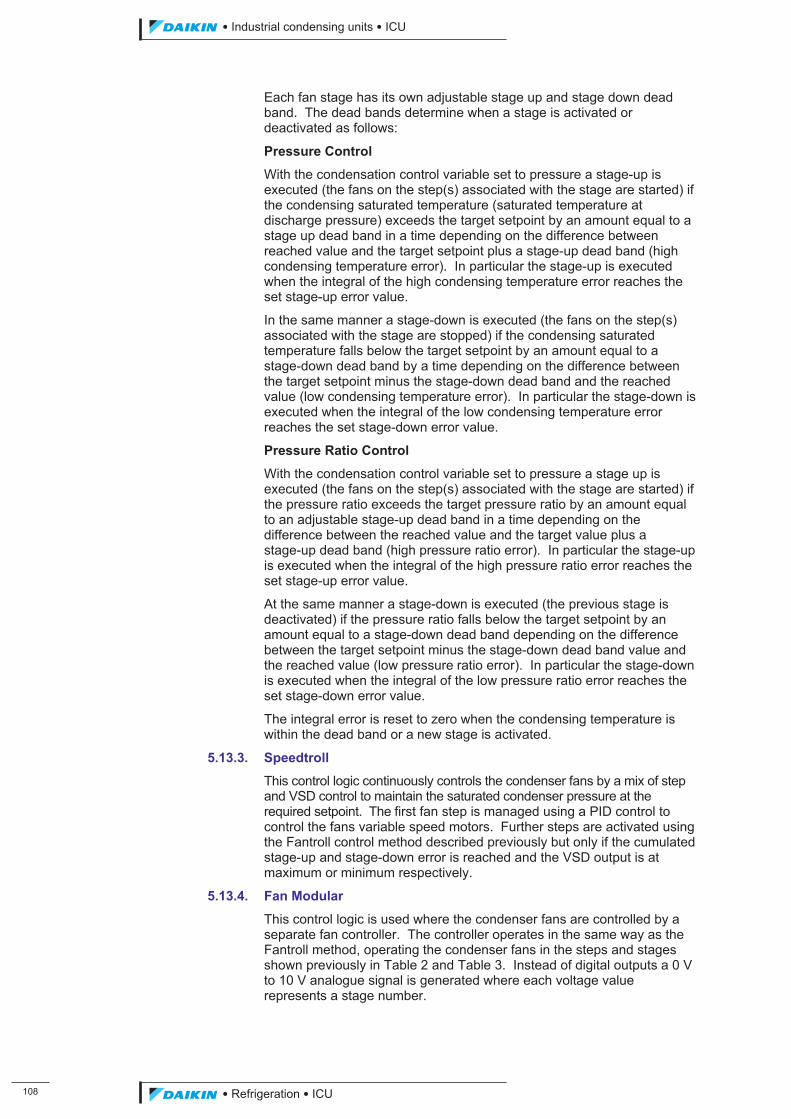
� �
��������� ����������������������
������������������
Each fan stage has its own adjustable stage up and stage down dead band. The dead bands determine when a stage is activated or deactivated as follows:
Pressure Control
With the condensation control variable set to pressure a stage-up is executed (the fans on the step(s) associated with the stage are started) if the condensing saturated temperature (saturated temperature at discharge pressure) exceeds the target setpoint by an amount equal to a stage up dead band in a time depending on the difference between reached value and the target setpoint plus a stage-up dead band (high condensing temperature error). In particular the stage-up is executed when the integral of the high condensing temperature error reaches the set stage-up error value.
In the same manner a stage-down is executed (the fans on the step(s) associated with the stage are stopped) if the condensing saturated temperature falls below the target setpoint by an amount equal to a stage-down dead band by a time depending on the difference between the target setpoint minus the stage-down dead band and the reached value (low condensing temperature error). In particular the stage-down is executed when the integral of the low condensing temperature error reaches the set stage-down error value.
Pressure Ratio Control
With the condensation control variable set to pressure a stage up is executed (the fans on the step(s) associated with the stage are started) if the pressure ratio exceeds the target pressure ratio by an amount equal to an adjustable stage-up dead band in a time depending on the difference between the reached value and the target value plus a stage-up dead band (high pressure ratio error). In particular the stage-up is executed when the integral of the high pressure ratio error reaches the set stage-up error value.
At the same manner a stage-down is executed (the previous stage is deactivated) if the pressure ratio falls below the target setpoint by an amount equal to a stage-down dead band depending on the difference between the target setpoint minus the stage-down dead band value and the reached value (low pressure ratio error). In particular the stage-down is executed when the integral of the low pressure ratio error reaches the set stage-down error value.
The integral error is reset to zero when the condensing temperature is within the dead band or a new stage is activated.
5.13.3. Speedtroll
This control logic continuously controls the condenser fans by a mix of step and VSD control to maintain the saturated condenser pressure at the required setpoint. The first fan step is managed using a PID control to control the fans variable speed motors. Further steps are activated using the Fantroll control method described previously but only if the cumulated stage-up and stage-down error is reached and the VSD output is at maximum or minimum respectively.
5.13.4. Fan Modular
This control logic is used where the condenser fans are controlled by a separate fan controller. The controller operates in the same way as the Fantroll method, operating the condenser fans in the steps and stages shown previously in Table 2 and Table 3. Instead of digital outputs a 0 V to 10 V analogue signal is generated where each voltage value represents a stage number.
ICU.pdf 116 26/01/2011 11:11:49
��������� ����������������������
������������������ � �
5.14. Liquid Injection
Liquid refrigerant can be injected into the compressor(s) to aid cooling. The compressor(s) discharge temperature is constantly monitored by the controller and a digital output signal is generated when the temperature rises above an adjustable setpoint. The digital output signal is used as the driver to divert refrigerant to the compressor. Liquid injection continues until the digital output signal is removed which occurs when the discharge temperature falls below the discharge setpoint by an adjustable amount.
ICU.pdf 117 26/01/2011 11:11:49
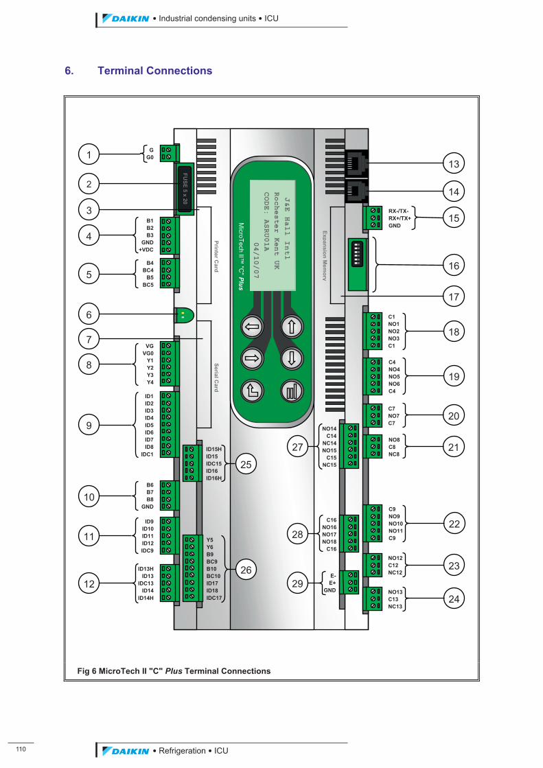
��
��������� ����������������������
������������������
6. Terminal Connections
Fig 6 MicroTech II "C" Plus Terminal Connections
J&E Hall Intl
Rochester Kent UK
CODE: ASRU01A
04/10/07
MicroTech II™
"C" Plus
FUSE 5 x 20
Printer Card
SerialCard
Ex pansion Mem
ory
GG0
B1B2B3
GND+VDC
B4BC4
B5BC5
VGVG0
Y1Y2Y3Y4
ID1ID2ID3ID4ID5ID6ID7ID8
IDC1ID15H ID15 IDC15 ID16 ID16H
B6B7B8
GND
ID9ID10ID11ID12IDC9
ID13HID13
IDC13ID14
ID14H
RX-/TX- RX+/TX+ GND
C1 NO1 NO2 NO3 C1
C4 NO4 NO5 NO6 C4
C7 NO7 C7
NO8 C8 NC8
NO12 C12 NC12
NO13 C13 NC13
C9 NO9 NO10 NO11 C9
C16NO16NO17NO18
C16
2
1
4
3
5
6
7
8
9
10
11
12
18
24
23
29
2822
27 21
20
19
17
16
15
14
13
Y5 Y6 B9 BC9 B10 BC10 ID17 ID18 IDC17
26
25
NO14C14
NC14NO15
C15NC15
E-E+
GND
ICU.pdf 118 26/01/2011 11:11:50
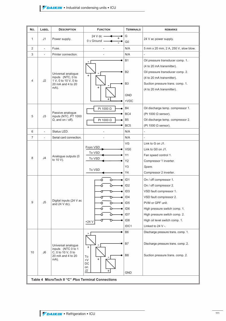
��������� ����������������������
������������������ ���
NO. LABEL DESCRIPTION FUNCTION TERMINALS REMARKS
1 J1 Power supply. G
G0 24 V ac power supply.
2 - Fuse. - N/A 5 mm x 20 mm, 2 A, 250 V, slow blow.
3 - Printer connection. - N/A -
4 J2
Universal analogue inputs (NTC, 0 to 1 V, 0 to 10 V, 0 to 20 mA and 4 to 20 mA).
B1
B2
B3
GND
+VDC
Oil pressure transducer comp. 1.
(4 to 20 mA transmitter).
Oil pressure transducer comp. 2.
(4 to 20 mA transmitter).
Suction pressure trans. comp. 1.
(4 to 20 mA transmitter).
5 J3 Passive analogue inputs (NTC, PT 1000 ', and on / off).
B4
BC4
B5
BC5
Oil discharge temp. compressor 1.
(Pt 1000 ' sensor).
Oil discharge temp. compressor 2.
(Pt 1000 ' sensor).
6 - Status LED. - N/A -
7 - Serial card connection. - N/A -
8 J4 Analogue outputs (0 to 10 V).
VG
VG0
Y1
Y2
Y3
Y4
Link to G on J1.
Link to G0 on J1.
Fan speed control 1.
Compressor 1 inverter.
Spare.
Compressor 2 inverter.
9 J5 Digital inputs (24 V ac and 24 V dc).
ID1
ID2
ID3
ID4
ID5
ID6
ID7
ID8
IDC1
On / off compressor 1.
On / off compressor 2.
VSD fault compressor 1.
VSD fault compressor 2.
PVM or GPF unit.
High pressure switch comp. 1.
High pressure switch comp. 2.
High oil level switch comp. 1.
Linked to 24 V -.
10 J6
Universal analogue inputs (NTC 0 to 1 C, 0 to 10 V, 0 to 20 mA and 4 to 20 mA).
B6
B7
B8
GND
Discharge pressure trans. comp. 1.
Discharge pressure trans. comp. 2.
Suction pressure trans. comp. 2.
Table 4 MicroTech II “C” Plus Terminal Connections
+
+
+
-
-To +V DC on J2
-
Pt 1000 '
Pt 1000 '
+
+
+
-
-
+24 V
+-
24 V dc0 v Ground
From VSD
To VSD
To VSD
To VSD
-
ICU.pdf 119 26/01/2011 11:11:50
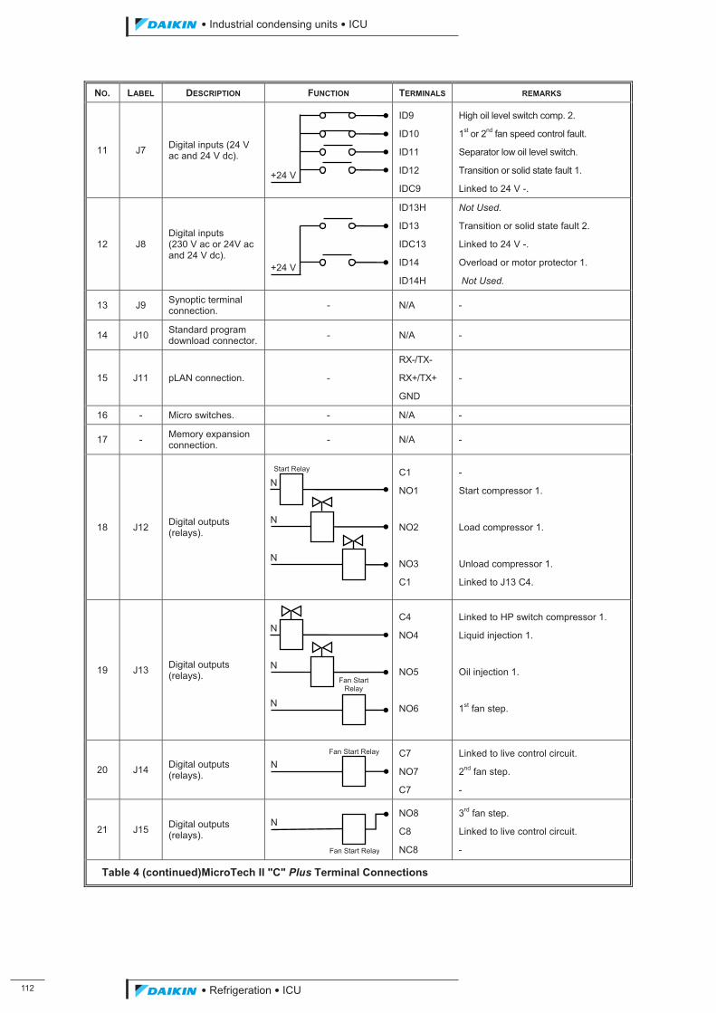
���
��������� ����������������������
������������������
NO. LABEL DESCRIPTION FUNCTION TERMINALS REMARKS
11 J7 Digital inputs (24 V ac and 24 V dc).
ID9
ID10
ID11
ID12
IDC9
High oil level switch comp. 2.
1st or 2nd fan speed control fault.
Separator low oil level switch.
Transition or solid state fault 1.
Linked to 24 V -.
12 J8 Digital inputs (230 V ac or 24V ac and 24 V dc).
ID13H
ID13
IDC13
ID14
ID14H
Not Used.
Transition or solid state fault 2.
Linked to 24 V -.
Overload or motor protector 1.
Not Used.
13 J9 Synoptic terminal connection. - N/A -
14 J10 Standard program download connector. - N/A -
15 J11 pLAN connection. -
RX-/TX-
RX+/TX+
GND
-
16 - Micro switches. - N/A -
17 - Memory expansion connection. - N/A -
18 J12 Digital outputs (relays).
C1
NO1
NO2
NO3
C1
-
Start compressor 1.
Load compressor 1.
Unload compressor 1.
Linked to J13 C4.
19 J13 Digital outputs (relays).
C4
NO4
NO5
NO6
Linked to HP switch compressor 1.
Liquid injection 1.
Oil injection 1.
1st fan step.
20 J14 Digital outputs (relays).
C7
NO7
C7
Linked to live control circuit.
2nd fan step.
-
21 J15 Digital outputs (relays).
NO8
C8
NC8
3rd fan step.
Linked to live control circuit.
-
Table 4 (continued)MicroTech II "C" Plus Terminal Connections
N
Fan Start Relay
N Fan Start Relay
N
N
N
Fan Start Relay
N
N
N Start Relay
+24 V
+24 V
ICU.pdf 120 26/01/2011 11:11:50
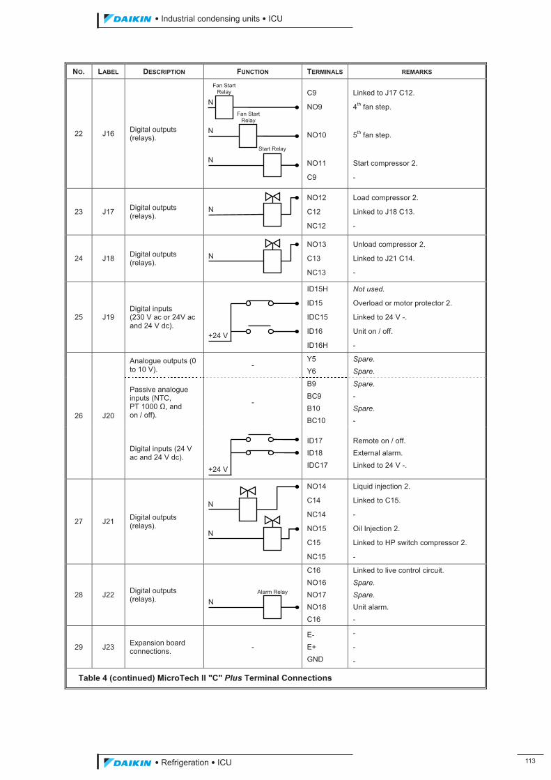
��������� ����������������������
������������������ ���
NO. LABEL DESCRIPTION FUNCTION TERMINALS REMARKS
22 J16 Digital outputs (relays).
C9
NO9
NO10
NO11
C9
Linked to J17 C12.
4th fan step.
5th fan step.
Start compressor 2.
-
23 J17 Digital outputs (relays).
NO12
C12
NC12
Load compressor 2.
Linked to J18 C13.
-
24 J18 Digital outputs (relays).
NO13
C13
NC13
Unload compressor 2.
Linked to J21 C14.
-
25 J19 Digital inputs (230 V ac or 24V ac and 24 V dc).
ID15H
ID15
IDC15
ID16
ID16H
Not used.
Overload or motor protector 2.
Linked to 24 V -.
Unit on / off.
-
26 J20
Analogue outputs (0 to 10 V). -
Y5 Y6
Spare.
Spare.
Passive analogue inputs (NTC, PT 1000 ', and on / off).
-
B9 BC9 B10 BC10
Spare. - Spare. -
Digital inputs (24 V ac and 24 V dc).
ID17 ID18 IDC17
Remote on / off. External alarm. Linked to 24 V -.
27 J21 Digital outputs (relays).
NO14
C14
NC14
NO15
C15
NC15
Liquid injection 2.
Linked to C15.
-
Oil Injection 2.
Linked to HP switch compressor 2.
-
28 J22 Digital outputs (relays).
C16 NO16 NO17 NO18 C16
Linked to live control circuit. Spare.
Spare. Unit alarm. -
29 J23 Expansion board connections. -
E- E+ GND
-
-
-
Table 4 (continued) MicroTech II "C" Plus Terminal Connections
N
N
N
N Alarm Relay
+24 V
+24 V
N
N
N
N
Start Relay
Fan Start Relay
Fan Start Relay
ICU.pdf 121 26/01/2011 11:11:50
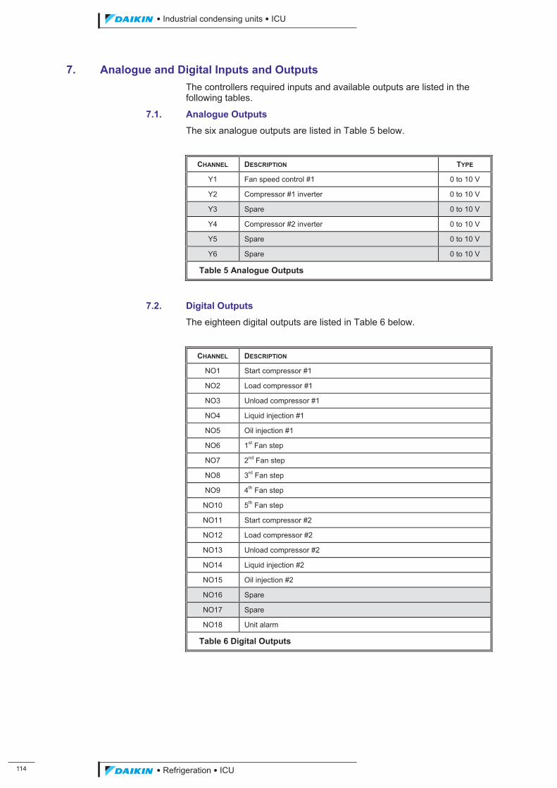
���
��������� ����������������������
������������������
7. Analogue and Digital Inputs and Outputs The controllers required inputs and available outputs are listed in the following tables.
7.1. Analogue Outputs
The six analogue outputs are listed in Table 5 below.
CHANNEL DESCRIPTION TYPE
Y1 Fan speed control #1 0 to 10 V
Y2 Compressor #1 inverter 0 to 10 V
Y3 Spare 0 to 10 V
Y4 Compressor #2 inverter 0 to 10 V
Y5 Spare 0 to 10 V
Y6 Spare 0 to 10 V
Table 5 Analogue Outputs
7.2. Digital Outputs
The eighteen digital outputs are listed in Table 6 below.
CHANNEL DESCRIPTION
NO1 Start compressor #1
NO2 Load compressor #1
NO3 Unload compressor #1
NO4 Liquid injection #1
NO5 Oil injection #1
NO6 1st Fan step
NO7 2nd Fan step
NO8 3rd Fan step
NO9 4th Fan step
NO10 5th Fan step
NO11 Start compressor #2
NO12 Load compressor #2
NO13 Unload compressor #2
NO14 Liquid injection #2
NO15 Oil injection #2
NO16 Spare
NO17 Spare
NO18 Unit alarm
Table 6 Digital Outputs
ICU.pdf 122 26/01/2011 11:11:50
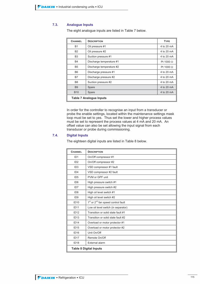
��������� ����������������������
������������������ ���
7.3. Analogue Inputs
The eight analogue inputs are listed in Table 7 below.
CHANNEL DESCRIPTION TYPE
B1 Oil pressure #1 4 to 20 mA
B2 Oil pressure #2 4 to 20 mA
B3 Suction pressure #1 4 to 20 mA
B4 Discharge temperature #1 Pt 1000 �
B5 Discharge temperature #2 Pt 1000 �
B6 Discharge pressure #1 4 to 20 mA
B7 Discharge pressure #2 4 to 20 mA
B8 Suction pressure #2 4 to 20 mA
B9 Spare 4 to 20 mA
B10 Spare 4 to 20 mA
Table 7 Analogue Inputs
In order for the controller to recognise an input from a transducer or probe the enable settings, located within the maintenance settings mask loop must be set to yes. Thus set the lower and higher process values must be set to represent the process values at 4 mA and 20 mA. An offset value can also be set allowing the input signal from each transducer or probe during commissioning.
7.4. Digital Inputs
The eighteen digital inputs are listed in Table 8 below.
CHANNEL DESCRIPTION
ID1 On/Off compressor #1
ID2 On/Off compressor #2
ID3 VSD compressor #1 fault
ID4 VSD compressor #2 fault
ID5 PVM or GPF unit
ID6 High pressure switch #1
ID7 High pressure switch #2
ID8 High oil level switch #1
ID9 High oil level switch #2
ID10 1st or 2nd fan speed control fault
ID11 Low oil level switch (in separator)
ID12 Transition or solid state fault #1
ID13 Transition or solid state fault #2
ID14 Overload or motor protector #1
ID15 Overload or motor protector #2
ID16 Unit On/Off
ID17 Remote On/Off
ID18 External alarm
Table 8 Digital Inputs
ICU.pdf 123 26/01/2011 11:11:50
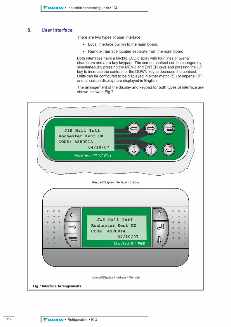
���
��������� ����������������������
������������������
8. User Interface There are two types of user interface:
� Local interface built-in to the main board.
� Remote interface located separate from the main board.
Both interfaces have a backlit, LCD display with four lines of twenty characters and a six key keypad. The screen contrast can be changed by simultaneously pressing the MENU and ENTER keys and pressing the UP key to increase the contrast or the DOWN key to decrease the contrast. Units can be configured to be displayed in either metric (SI) or imperial (IP) and all screen displays are displayed in English.
The arrangement of the display and keypad for both types of interface are shown below in Fig 7.
Keypad/Display Interface - Built-in
Keypad/Display Interface - Remote
Fig 7 Interface Arrangements
J&E Hall Intl Rochester Kent UK CODE: ASRU01A 04/10/07
MicroTech II™ "C" Plus
J&E Hall Intl Rochester Kent UK CODE: ASRU01A 04/10/07
MicroTech II™ PGD
ICU.pdf 124 26/01/2011 11:11:50
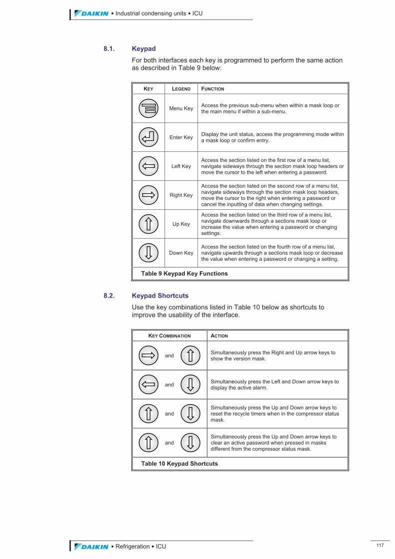
��������� ����������������������
������������������ ���
8.1. Keypad
For both interfaces each key is programmed to perform the same action as described in Table 9 below:
KEY LEGEND FUNCTION
Menu Key Access the previous sub-menu when within a mask loop or the main menu if within a sub-menu.
Enter Key Display the unit status, access the programming mode within a mask loop or confirm entry.
Left Key Access the section listed on the first row of a menu list, navigate sideways through the section mask loop headers or move the cursor to the left when entering a password.
Right Key
Access the section listed on the second row of a menu list, navigate sideways through the section mask loop headers, move the cursor to the right when entering a password or cancel the inputting of data when changing settings.
Up Key
Access the section listed on the third row of a menu list, navigate downwards through a sections mask loop or increase the value when entering a password or changing settings.
Down Key Access the section listed on the fourth row of a menu list, navigate upwards through a sections mask loop or decrease the value when entering a password or changing a setting.
Table 9 Keypad Key Functions
8.2. Keypad Shortcuts
Use the key combinations listed in Table 10 below as shortcuts to improve the usability of the interface.
KEY COMBINATION ACTION
and
Simultaneously press the Right and Up arrow keys to show the version mask.
and
Simultaneously press the Left and Down arrow keys to display the active alarm.
and
Simultaneously press the Up and Down arrow keys to reset the recycle timers when in the compressor status mask.
and
Simultaneously press the Up and Down arrow keys to clear an active password when pressed in masks different from the compressor status mask.
Table 10 Keypad Shortcuts
ICU.pdf 125 26/01/2011 11:11:50
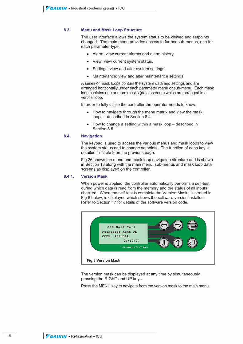
���
��������� ����������������������
������������������
8.3. Menu and Mask Loop Structure
The user interface allows the system status to be viewed and setpoints changed. The main menu provides access to further sub-menus, one for each parameter type:
� Alarm: view current alarms and alarm history.
� View: view current system status.
� Settings: view and alter system settings.
� Maintenance: view and alter maintenance settings.
A series of mask loops contain the system data and settings and are arranged horizontally under each parameter menu or sub-menu. Each mask loop contains one or more masks (data screens) which are arranged in a vertical loop.
In order to fully utilise the controller the operator needs to know:
� How to navigate through the menu matrix and view the mask loops – described in Section 8.4.
� How to change a setting within a mask loop – described in Section 8.5.
8.4. Navigation
The keypad is used to access the various menus and mask loops to view the system status and to change setpoints. The function of each key is detailed in Table 9 on the previous page.
Fig 26 shows the menu and mask loop navigation structure and is shown in Section 13 along with the main menu, sub-menus and mask loop data screens as displayed on the controller.
8.4.1. Version Mask
When power is applied, the controller automatically performs a self-test during which data is read from the memory and the status of all inputs checked. When the self-test is complete the Version Mask, illustrated in Fig 8 below, is displayed which shows the software version installed. Refer to Section 17 for details of the software version code.
Fig 8 Version Mask
The version mask can be displayed at any time by simultaneously pressing the RIGHT and UP keys.
Press the MENU key to navigate from the version mask to the main menu.
J&E Hall Intl Rochester Kent UK CODE: ASRU01A 04/10/07
MicroTech II™ "C" Plus
ICU.pdf 126 26/01/2011 11:11:51
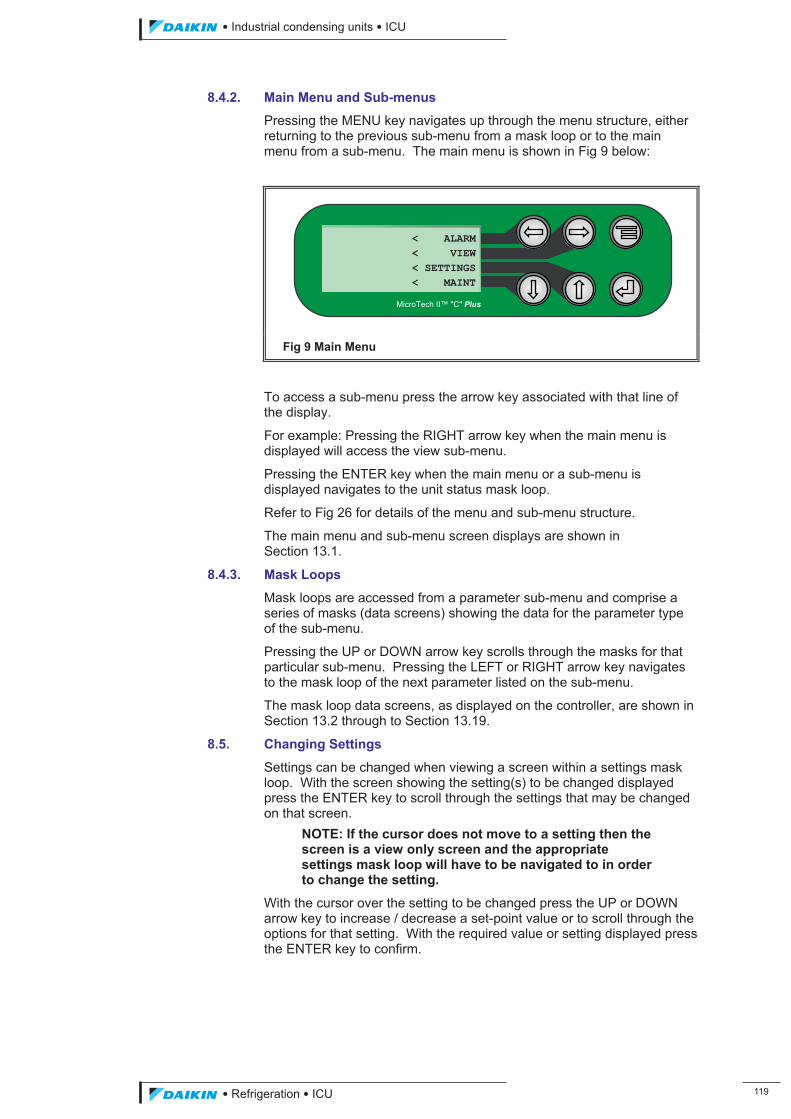
��������� ����������������������
������������������ ���
8.4.2. Main Menu and Sub-menus
Pressing the MENU key navigates up through the menu structure, either returning to the previous sub-menu from a mask loop or to the main menu from a sub-menu. The main menu is shown in Fig 9 below:
Fig 9 Main Menu
To access a sub-menu press the arrow key associated with that line of the display.
For example: Pressing the RIGHT arrow key when the main menu is displayed will access the view sub-menu.
Pressing the ENTER key when the main menu or a sub-menu is displayed navigates to the unit status mask loop.
Refer to Fig 26 for details of the menu and sub-menu structure.
The main menu and sub-menu screen displays are shown in Section 13.1.
8.4.3. Mask Loops
Mask loops are accessed from a parameter sub-menu and comprise a series of masks (data screens) showing the data for the parameter type of the sub-menu.
Pressing the UP or DOWN arrow key scrolls through the masks for that particular sub-menu. Pressing the LEFT or RIGHT arrow key navigates to the mask loop of the next parameter listed on the sub-menu.
The mask loop data screens, as displayed on the controller, are shown in Section 13.2 through to Section 13.19.
8.5. Changing Settings
Settings can be changed when viewing a screen within a settings mask loop. With the screen showing the setting(s) to be changed displayed press the ENTER key to scroll through the settings that may be changed on that screen.
NOTE: If the cursor does not move to a setting then the screen is a view only screen and the appropriate settings mask loop will have to be navigated to in order to change the setting.
With the cursor over the setting to be changed press the UP or DOWN arrow key to increase / decrease a set-point value or to scroll through the options for that setting. With the required value or setting displayed press the ENTER key to confirm.
< ALARM< VIEW< SETTINGS< MAINT
MicroTech II™ "C" Plus
ICU.pdf 127 26/01/2011 11:11:51
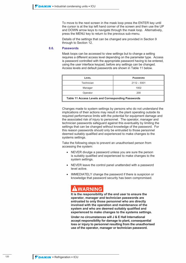
��
��������� ����������������������
������������������
To move to the next screen in the mask loop press the ENTER key until the cursor is at the top left hand corner of the screen and then use the UP and DOWN arrow keys to navigate through the mask loop. Alternatively, press the MENU key to return to the previous sub-menu.
Details of the settings that can be changed are provided in Section 9 through to Section 12.
8.6. Passwords
Mask loops can be accessed to view settings but to change a setting requires a different access level depending on the parameter type. Access is password controlled with the appropriate password having to be entered, using the user interface keypad, before any settings can be changed. Access levels and default passwords are shown in Table 11 below.
LEVEL PASSWORD
Technician 2112 – 9301
Manager 1002
Operator 200
Table 11 Access Levels and Corresponding Passwords
Changes made to system settings by persons who do not understand the implications of their actions may result in the plant operating outside its required performance limits with the potential for equipment damage and the associated risk of injury to personnel. The operator, manager and technician passwords safeguard against this eventuality by limiting the settings that can be changed without knowledge of the password. For this reason passwords should only be entrusted to those personnel deemed suitably qualified and experienced to make changes to the systems settings.
Take the following steps to prevent an unauthorised person from accessing the system:
� NEVER divulge a password unless you are sure the person is suitably qualified and experienced to make changes to the system settings.
� NEVER leave the control panel unattended with a password level active.
� IMMEDIATELY change the password if there is suspicion or knowledge that password security has been compromised.
�WARNING It is the responsibility of the end user to ensure the operator, manager and technician passwords are entrusted to only those personnel who are directly involved with the operation and maintenance of the system and who are deemed suitably qualified and experienced to make changes to the systems settings. Under no circumstances will J & E Hall International accept responsibility for damage to plant, consequential loss or injury to personnel resulting from the unauthorised use of the operator, manager or technician password.
ICU.pdf 128 26/01/2011 11:11:51
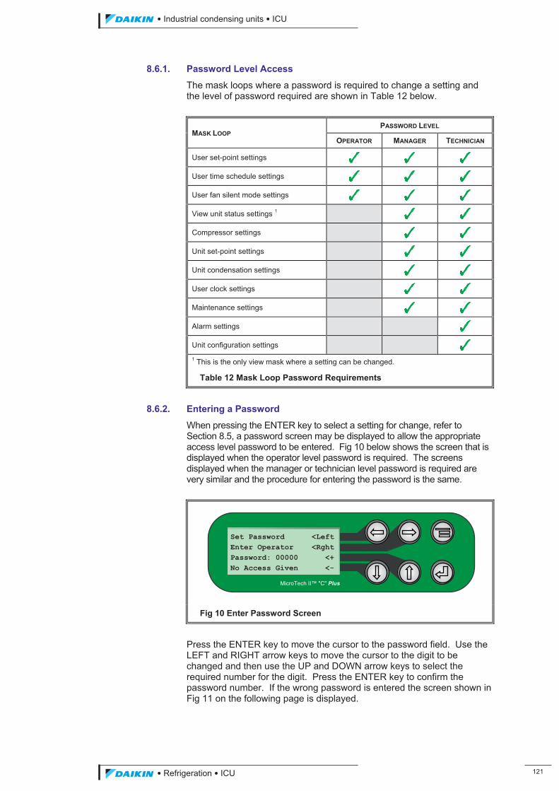
��������� ����������������������
������������������ ���
8.6.1. Password Level Access
The mask loops where a password is required to change a setting and the level of password required are shown in Table 12 below.
MASK LOOP PASSWORD LEVEL
OPERATOR MANAGER TECHNICIAN
User set-point settings
User time schedule settings
User fan silent mode settings
View unit status settings 1
Compressor settings
Unit set-point settings
Unit condensation settings
User clock settings
Maintenance settings
Alarm settings
Unit configuration settings 1 This is the only view mask where a setting can be changed.
Table 12 Mask Loop Password Requirements
8.6.2. Entering a Password
When pressing the ENTER key to select a setting for change, refer to Section 8.5, a password screen may be displayed to allow the appropriate access level password to be entered. Fig 10 below shows the screen that is displayed when the operator level password is required. The screens displayed when the manager or technician level password is required are very similar and the procedure for entering the password is the same.
Fig 10 Enter Password Screen
Press the ENTER key to move the cursor to the password field. Use the LEFT and RIGHT arrow keys to move the cursor to the digit to be changed and then use the UP and DOWN arrow keys to select the required number for the digit. Press the ENTER key to confirm the password number. If the wrong password is entered the screen shown in Fig 11 on the following page is displayed.
Set Password <LeftEnter Operator <RghtPassword: 00000 <+No Access Given <-
MicroTech II™ "C" Plus
ICU.pdf 129 26/01/2011 11:11:51
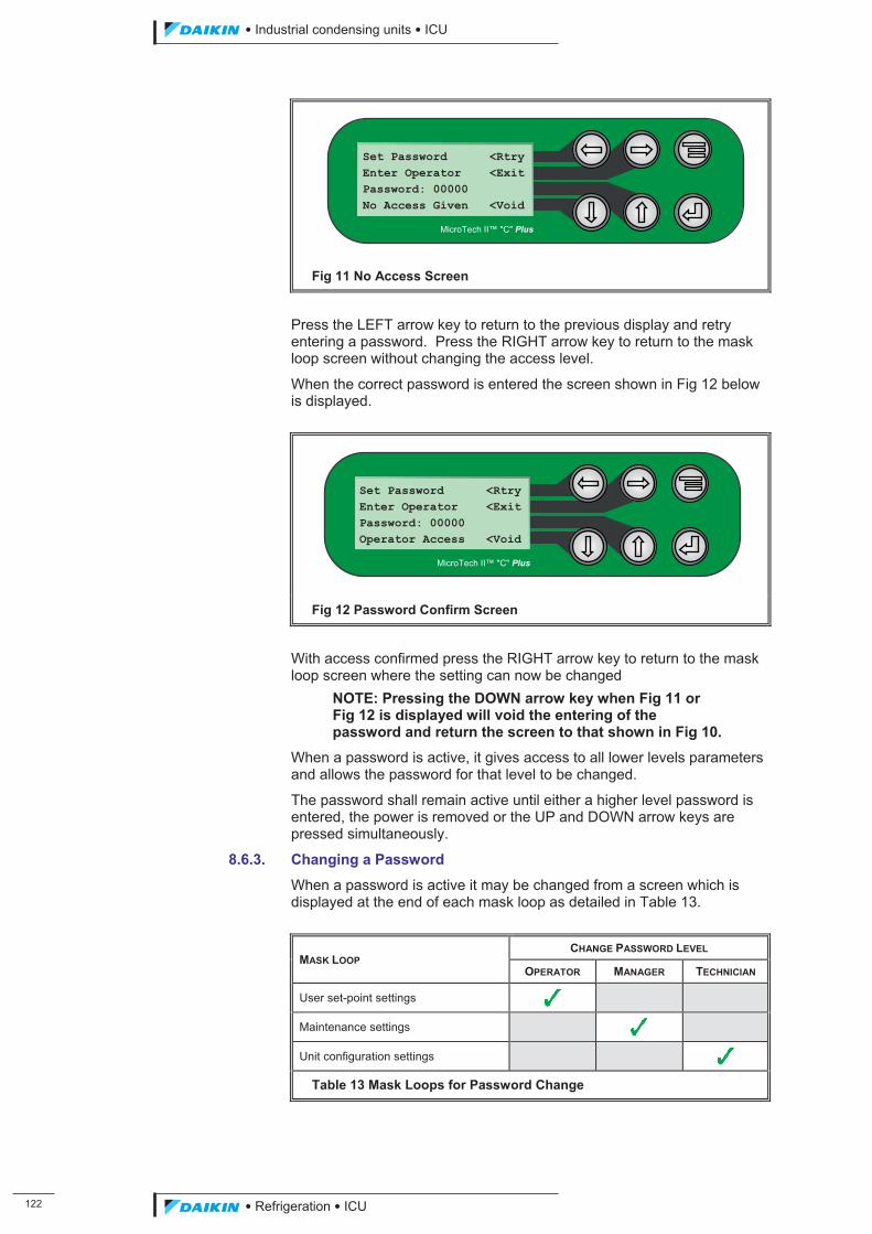
���
��������� ����������������������
������������������
Fig 11 No Access Screen
Press the LEFT arrow key to return to the previous display and retry entering a password. Press the RIGHT arrow key to return to the mask loop screen without changing the access level.
When the correct password is entered the screen shown in Fig 12 below is displayed.
Fig 12 Password Confirm Screen
With access confirmed press the RIGHT arrow key to return to the mask loop screen where the setting can now be changed
NOTE: Pressing the DOWN arrow key when Fig 11 or Fig 12 is displayed will void the entering of the password and return the screen to that shown in Fig 10.
When a password is active, it gives access to all lower levels parameters and allows the password for that level to be changed.
The password shall remain active until either a higher level password is entered, the power is removed or the UP and DOWN arrow keys are pressed simultaneously.
8.6.3. Changing a Password
When a password is active it may be changed from a screen which is displayed at the end of each mask loop as detailed in Table 13.
MASK LOOP CHANGE PASSWORD LEVEL
OPERATOR MANAGER TECHNICIAN
User set-point settings
Maintenance settings
Unit configuration settings
Table 13 Mask Loops for Password Change
Set Password <RtryEnter Operator <ExitPassword: 00000 Operator Access <Void
MicroTech II™ "C" Plus
Set Password <RtryEnter Operator <ExitPassword: 00000 No Access Given <Void
MicroTech II™ "C" Plus
ICU.pdf 130 26/01/2011 11:11:51
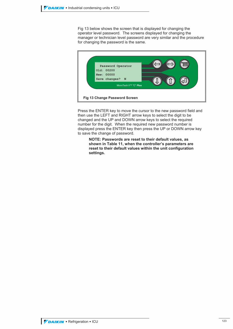
��������� ����������������������
������������������ ���
Fig 13 below shows the screen that is displayed for changing the operator level password. The screens displayed for changing the manager or technician level password are very similar and the procedure for changing the password is the same.
Fig 13 Change Password Screen
Press the ENTER key to move the cursor to the new password field and then use the LEFT and RIGHT arrow keys to select the digit to be changed and the UP and DOWN arrow keys to select the required number for the digit. When the required new password number is displayed press the ENTER key then press the UP or DOWN arrow key to save the change of password.
NOTE: Passwords are reset to their default values, as shown in Table 11, when the controller’s parameters are reset to their default values within the unit configuration settings.
Password Operator Old: 00200 New: 00000 Save changes? N
MicroTech II™ "C" Plus
ICU.pdf 131 26/01/2011 11:11:51
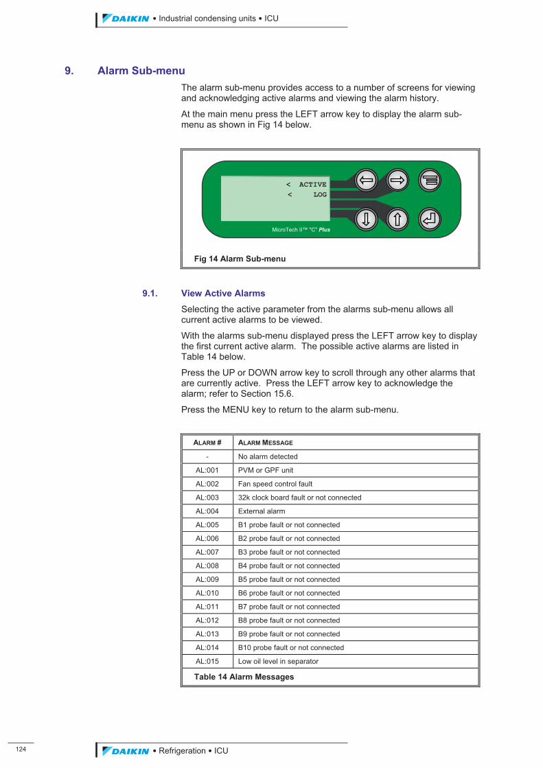
���
��������� ����������������������
������������������
9. Alarm Sub-menu The alarm sub-menu provides access to a number of screens for viewing and acknowledging active alarms and viewing the alarm history.
At the main menu press the LEFT arrow key to display the alarm sub-menu as shown in Fig 14 below.
Fig 14 Alarm Sub-menu
9.1. View Active Alarms
Selecting the active parameter from the alarms sub-menu allows all current active alarms to be viewed.
With the alarms sub-menu displayed press the LEFT arrow key to display the first current active alarm. The possible active alarms are listed in Table 14 below.
Press the UP or DOWN arrow key to scroll through any other alarms that are currently active. Press the LEFT arrow key to acknowledge the alarm; refer to Section 15.6.
Press the MENU key to return to the alarm sub-menu.
ALARM # ALARM MESSAGE
- No alarm detected
AL:001 PVM or GPF unit
AL:002 Fan speed control fault
AL:003 32k clock board fault or not connected
AL:004 External alarm
AL:005 B1 probe fault or not connected
AL:006 B2 probe fault or not connected
AL:007 B3 probe fault or not connected
AL:008 B4 probe fault or not connected
AL:009 B5 probe fault or not connected
AL:010 B6 probe fault or not connected
AL:011 B7 probe fault or not connected
AL:012 B8 probe fault or not connected
AL:013 B9 probe fault or not connected
AL:014 B10 probe fault or not connected
AL:015 Low oil level in separator
Table 14 Alarm Messages
< ACTIVE< LOG
MicroTech II™ "C" Plus
ICU.pdf 132 26/01/2011 11:11:51
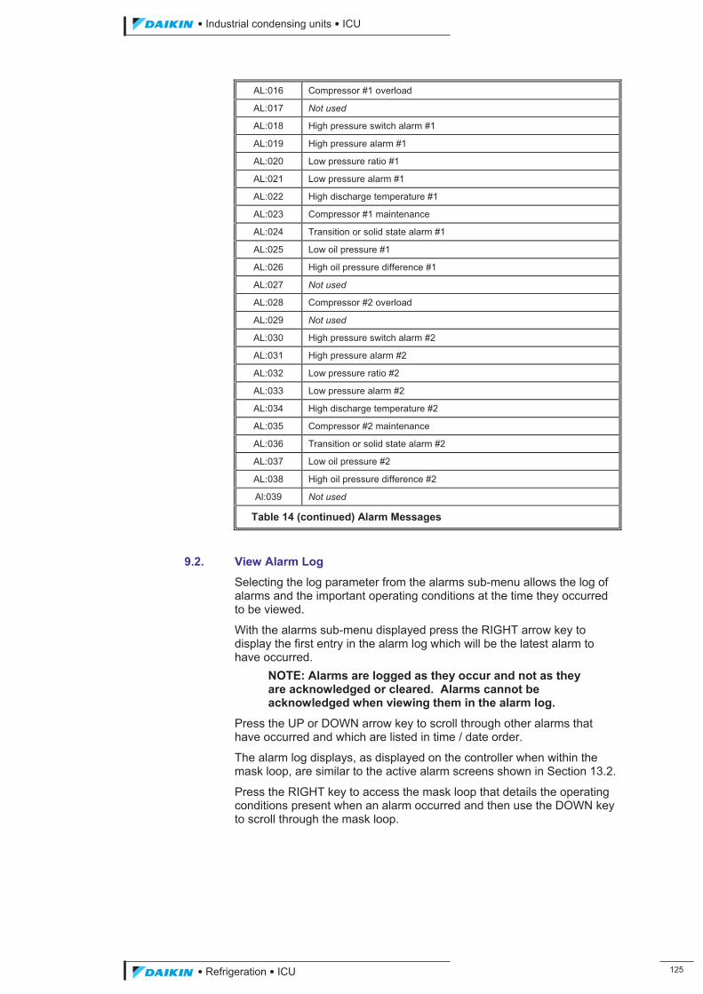
��������� ����������������������
������������������ ���
AL:016 Compressor #1 overload
AL:017 Not used
AL:018 High pressure switch alarm #1
AL:019 High pressure alarm #1
AL:020 Low pressure ratio #1
AL:021 Low pressure alarm #1
AL:022 High discharge temperature #1
AL:023 Compressor #1 maintenance
AL:024 Transition or solid state alarm #1
AL:025 Low oil pressure #1
AL:026 High oil pressure difference #1
AL:027 Not used
AL:028 Compressor #2 overload
AL:029 Not used
AL:030 High pressure switch alarm #2
AL:031 High pressure alarm #2
AL:032 Low pressure ratio #2
AL:033 Low pressure alarm #2
AL:034 High discharge temperature #2
AL:035 Compressor #2 maintenance
AL:036 Transition or solid state alarm #2
AL:037 Low oil pressure #2
AL:038 High oil pressure difference #2
Al:039 Not used
Table 14 (continued) Alarm Messages
9.2. View Alarm Log
Selecting the log parameter from the alarms sub-menu allows the log of alarms and the important operating conditions at the time they occurred to be viewed.
With the alarms sub-menu displayed press the RIGHT arrow key to display the first entry in the alarm log which will be the latest alarm to have occurred.
NOTE: Alarms are logged as they occur and not as they are acknowledged or cleared. Alarms cannot be acknowledged when viewing them in the alarm log.
Press the UP or DOWN arrow key to scroll through other alarms that have occurred and which are listed in time / date order.
The alarm log displays, as displayed on the controller when within the mask loop, are similar to the active alarm screens shown in Section 13.2.
Press the RIGHT key to access the mask loop that details the operating conditions present when an alarm occurred and then use the DOWN key to scroll through the mask loop.
ICU.pdf 133 26/01/2011 11:11:52
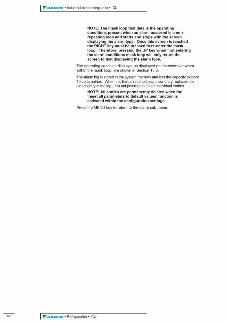
���
��������� ����������������������
������������������
NOTE: The mask loop that details the operating conditions present when an alarm occurred is a non-repeating loop and starts and stops with the screen displaying the alarm type. Once this screen is reached the RIGHT key must be pressed to re-enter the mask loop. Therefore, pressing the UP key when first entering the alarm conditions mask loop will only return the screen to that displaying the alarm type.
The operating condition displays, as displayed on the controller when within the mask loop, are shown in Section 13.3.
The alarm log is stored in the system memory and has the capacity to store 10 up to entries. When this limit is reached each new entry replaces the oldest entry in the log. It is not possible to delete individual entries.
NOTE: All entries are permanently deleted when the ‘reset all parameters to default values’ function is activated within the configuration settings.
Press the MENU key to return to the alarm sub-menu.
ICU.pdf 134 26/01/2011 11:11:52
��������� ����������������������
������������������ ���
10. View Sub-menu The view sub-menu provides access to a number or screens for viewing the current status of the system.
At the main menu press the RIGHT arrow key to display the view sub-menu as shown in Fig 15 below.
Fig 15 View Sub-menu
Selecting the unit parameter from the view sub-menu allows the current status of the system to be viewed, selecting the compressor parameter allows the current status of the compressor(s) to be viewed or selecting the I/O parameter allows the current status of the systems inputs and outputs to be viewed.
With the view sub-menu displayed press the LEFT arrow key to display the system status mask loop, the RIGHT arrow key to display the compressor(s) status mask loop or the UP key to display the systems inputs and outputs status mask loop.
Press the UP or DOWN arrow key to scroll through the screens within the mask loop. Press the LEFT or RIGHT arrow key to navigate to the mask loop of the next parameter listed on the sub-menu. The screens, as displayed on the controller within each mask loop, are shown in Section 13.4 through to Section 13.6.
Press the MENU key to return to the view sub-menu.
10.1. Capacity Control Setting
The switching between automatic and manual capacity control is the only setting that can be changed within the view series of menu masks.
NOTE: Changes can only be made to the settings within the view unit status mask loop with the system set at manager access level or higher.
To switch from the default automatic capacity control to manual capacity control press the LEFT arrow key from the view sub menu, shown in Fig 15 above, and use the DOWN arrow key to scroll through the view unit menu masks until the compressor #1 capacity control screen is displayed, as shown in Fig 16 on the following page.
< UNIT< COMPRESSOR< I/O
MicroTech II™ "C" Plus
ICU.pdf 135 26/01/2011 11:11:52
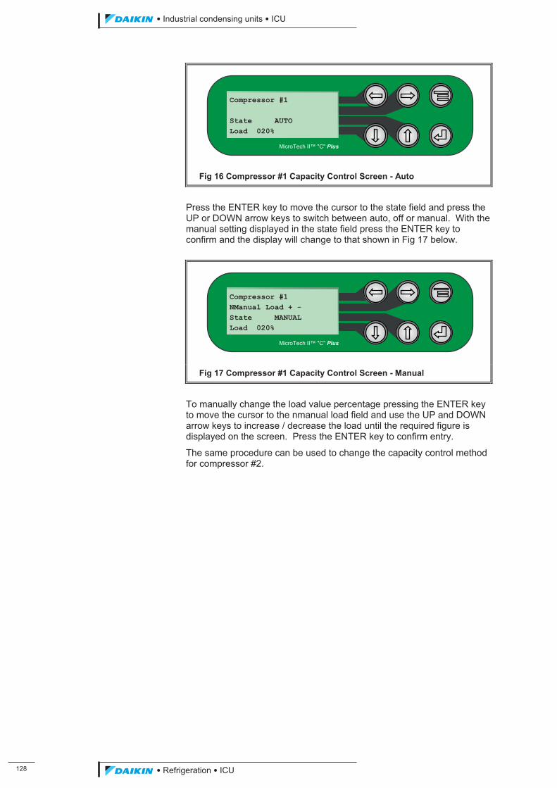
���
��������� ����������������������
������������������
Fig 16 Compressor #1 Capacity Control Screen - Auto
Press the ENTER key to move the cursor to the state field and press the UP or DOWN arrow keys to switch between auto, off or manual. With the manual setting displayed in the state field press the ENTER key to confirm and the display will change to that shown in Fig 17 below.
Fig 17 Compressor #1 Capacity Control Screen - Manual
To manually change the load value percentage pressing the ENTER key to move the cursor to the nmanual load field and use the UP and DOWN arrow keys to increase / decrease the load until the required figure is displayed on the screen. Press the ENTER key to confirm entry.
The same procedure can be used to change the capacity control method for compressor #2.
Compressor #1 NManual Load + - State MANUAL Load 020%
MicroTech II™ "C" Plus
Compressor #1 State AUTO Load 020%
MicroTech II™ "C" Plus
ICU.pdf 136 26/01/2011 11:11:52
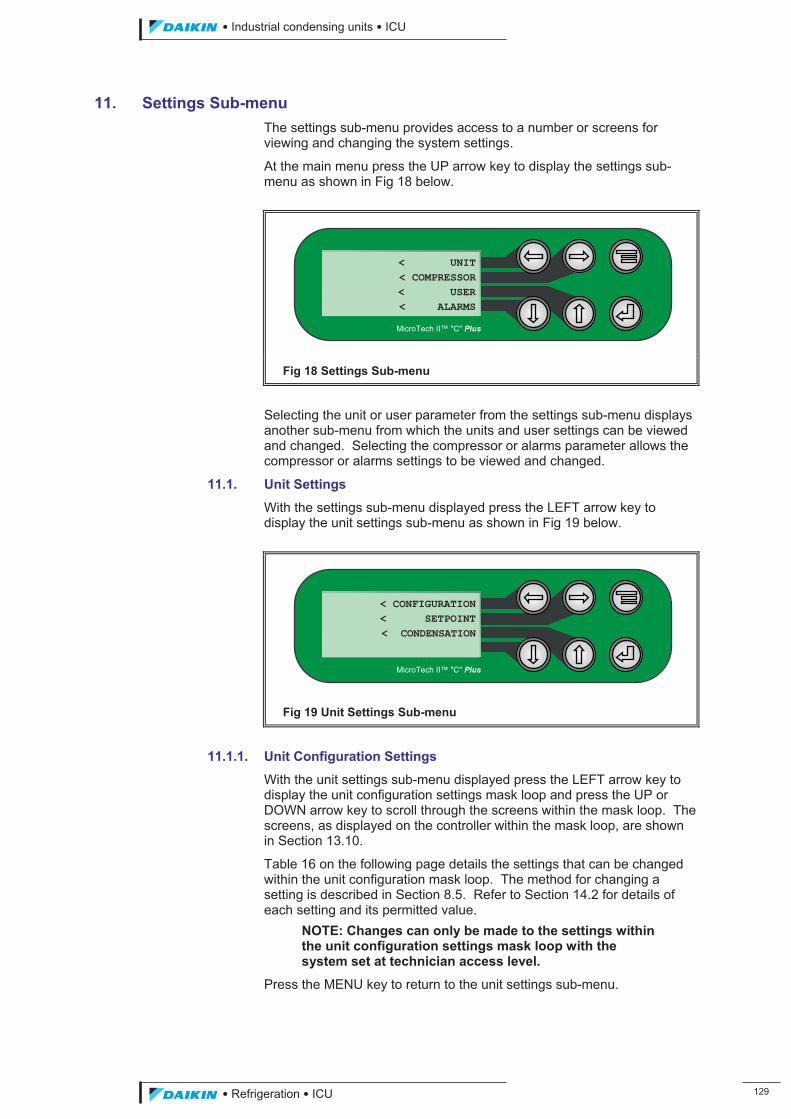
��������� ����������������������
������������������ ���
11. Settings Sub-menu The settings sub-menu provides access to a number or screens for viewing and changing the system settings.
At the main menu press the UP arrow key to display the settings sub-menu as shown in Fig 18 below.
Fig 18 Settings Sub-menu
Selecting the unit or user parameter from the settings sub-menu displays another sub-menu from which the units and user settings can be viewed and changed. Selecting the compressor or alarms parameter allows the compressor or alarms settings to be viewed and changed.
11.1. Unit Settings
With the settings sub-menu displayed press the LEFT arrow key to display the unit settings sub-menu as shown in Fig 19 below.
Fig 19 Unit Settings Sub-menu
11.1.1. Unit Configuration Settings
With the unit settings sub-menu displayed press the LEFT arrow key to display the unit configuration settings mask loop and press the UP or DOWN arrow key to scroll through the screens within the mask loop. The screens, as displayed on the controller within the mask loop, are shown in Section 13.10.
Table 16 on the following page details the settings that can be changed within the unit configuration mask loop. The method for changing a setting is described in Section 8.5. Refer to Section 14.2 for details of each setting and its permitted value.
NOTE: Changes can only be made to the settings within the unit configuration settings mask loop with the system set at technician access level.
Press the MENU key to return to the unit settings sub-menu.
< CONFIGURATION< SETPOINT< CONDENSATION
MicroTech II™ "C" Plus
< UNIT< COMPRESSOR< USER< ALARMS
MicroTech II™ "C" Plus
ICU.pdf 137 26/01/2011 11:11:52
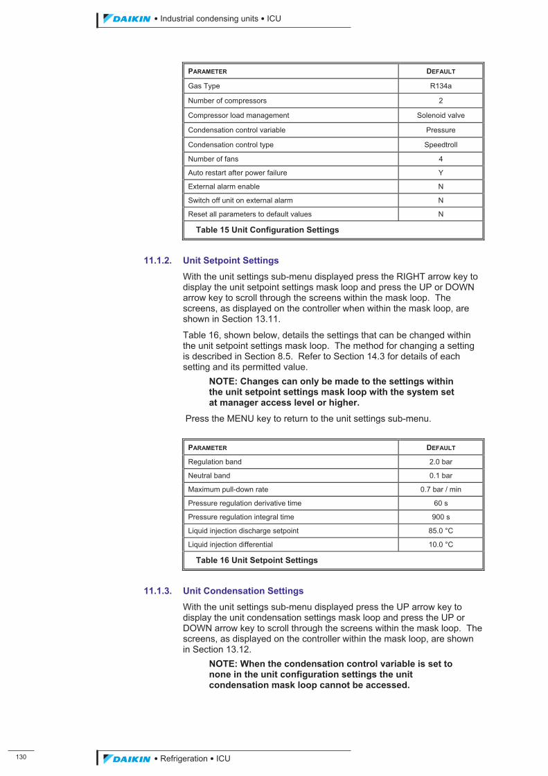
��
��������� ����������������������
������������������
PARAMETER DEFAULT
Gas Type R134a
Number of compressors 2
Compressor load management Solenoid valve
Condensation control variable Pressure
Condensation control type Speedtroll
Number of fans 4
Auto restart after power failure Y
External alarm enable N
Switch off unit on external alarm N
Reset all parameters to default values N
Table 15 Unit Configuration Settings
11.1.2. Unit Setpoint Settings
With the unit settings sub-menu displayed press the RIGHT arrow key to display the unit setpoint settings mask loop and press the UP or DOWN arrow key to scroll through the screens within the mask loop. The screens, as displayed on the controller when within the mask loop, are shown in Section 13.11.
Table 16, shown below, details the settings that can be changed within the unit setpoint settings mask loop. The method for changing a setting is described in Section 8.5. Refer to Section 14.3 for details of each setting and its permitted value.
NOTE: Changes can only be made to the settings within the unit setpoint settings mask loop with the system set at manager access level or higher.
Press the MENU key to return to the unit settings sub-menu.
PARAMETER DEFAULT
Regulation band 2.0 bar
Neutral band 0.1 bar
Maximum pull-down rate 0.7 bar / min
Pressure regulation derivative time 60 s
Pressure regulation integral time 900 s
Liquid injection discharge setpoint 85.0 °C
Liquid injection differential 10.0 °C
Table 16 Unit Setpoint Settings
11.1.3. Unit Condensation Settings
With the unit settings sub-menu displayed press the UP arrow key to display the unit condensation settings mask loop and press the UP or DOWN arrow key to scroll through the screens within the mask loop. The screens, as displayed on the controller within the mask loop, are shown in Section 13.12.
NOTE: When the condensation control variable is set to none in the unit configuration settings the unit condensation mask loop cannot be accessed.
ICU.pdf 138 26/01/2011 11:11:52
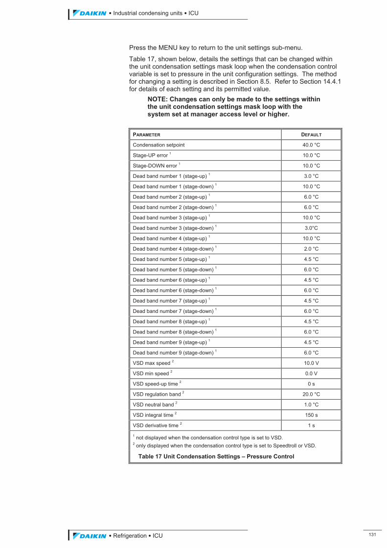
��������� ����������������������
������������������ ���
Press the MENU key to return to the unit settings sub-menu.
Table 17, shown below, details the settings that can be changed within the unit condensation settings mask loop when the condensation control variable is set to pressure in the unit configuration settings. The method for changing a setting is described in Section 8.5. Refer to Section 14.4.1 for details of each setting and its permitted value.
NOTE: Changes can only be made to the settings within the unit condensation settings mask loop with the system set at manager access level or higher.
PARAMETER DEFAULT
Condensation setpoint 40.0 °C
Stage-UP error 1 10.0 °C
Stage-DOWN error 1 10.0 °C
Dead band number 1 (stage-up) 1 3.0 °C
Dead band number 1 (stage-down) 1 10.0 °C
Dead band number 2 (stage-up) 1 6.0 °C
Dead band number 2 (stage-down) 1 6.0 °C
Dead band number 3 (stage-up) 1 10.0 °C
Dead band number 3 (stage-down) 1 3.0°C
Dead band number 4 (stage-up) 1 10.0 °C
Dead band number 4 (stage-down) 1 2.0 °C
Dead band number 5 (stage-up) 1 4.5 °C
Dead band number 5 (stage-down) 1 6.0 °C
Dead band number 6 (stage-up) 1 4.5 °C
Dead band number 6 (stage-down) 1 6.0 °C
Dead band number 7 (stage-up) 1 4.5 °C
Dead band number 7 (stage-down) 1 6.0 °C
Dead band number 8 (stage-up) 1 4.5 °C
Dead band number 8 (stage-down) 1 6.0 °C
Dead band number 9 (stage-up) 1 4.5 °C
Dead band number 9 (stage-down) 1 6.0 °C
VSD max speed 2 10.0 V
VSD min speed 2 0.0 V
VSD speed-up time 2 0 s
VSD regulation band 2 20.0 °C
VSD neutral band 2 1.0 °C
VSD integral time 2 150 s
VSD derivative time 2 1 s
1 not displayed when the condensation control type is set to VSD. 2 only displayed when the condensation control type is set to Speedtroll or VSD.
Table 17 Unit Condensation Settings – Pressure Control
ICU.pdf 139 26/01/2011 11:11:52
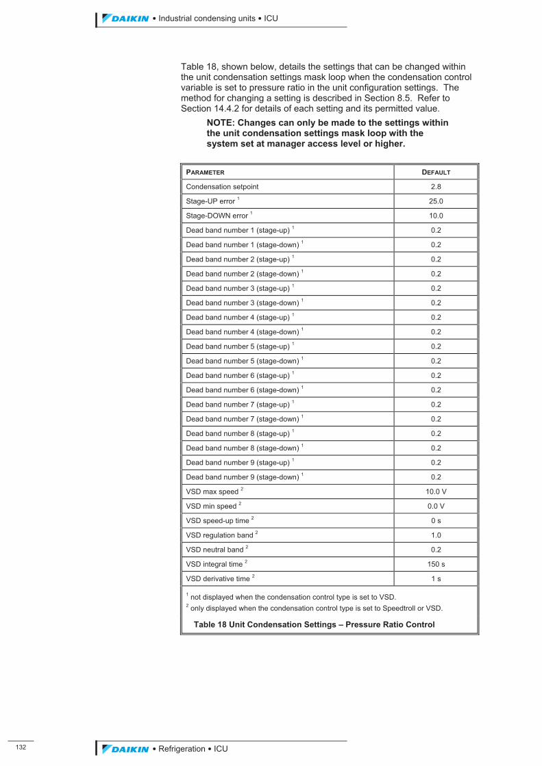
���
��������� ����������������������
������������������
Table 18, shown below, details the settings that can be changed within the unit condensation settings mask loop when the condensation control variable is set to pressure ratio in the unit configuration settings. The method for changing a setting is described in Section 8.5. Refer to Section 14.4.2 for details of each setting and its permitted value.
NOTE: Changes can only be made to the settings within the unit condensation settings mask loop with the system set at manager access level or higher.
PARAMETER DEFAULT
Condensation setpoint 2.8
Stage-UP error 1 25.0
Stage-DOWN error 1 10.0
Dead band number 1 (stage-up) 1 0.2
Dead band number 1 (stage-down) 1 0.2
Dead band number 2 (stage-up) 1 0.2
Dead band number 2 (stage-down) 1 0.2
Dead band number 3 (stage-up) 1 0.2
Dead band number 3 (stage-down) 1 0.2
Dead band number 4 (stage-up) 1 0.2
Dead band number 4 (stage-down) 1 0.2
Dead band number 5 (stage-up) 1 0.2
Dead band number 5 (stage-down) 1 0.2
Dead band number 6 (stage-up) 1 0.2
Dead band number 6 (stage-down) 1 0.2
Dead band number 7 (stage-up) 1 0.2
Dead band number 7 (stage-down) 1 0.2
Dead band number 8 (stage-up) 1 0.2
Dead band number 8 (stage-down) 1 0.2
Dead band number 9 (stage-up) 1 0.2
Dead band number 9 (stage-down) 1 0.2
VSD max speed 2 10.0 V
VSD min speed 2 0.0 V
VSD speed-up time 2 0 s
VSD regulation band 2 1.0
VSD neutral band 2 0.2
VSD integral time 2 150 s
VSD derivative time 2 1 s
1 not displayed when the condensation control type is set to VSD. 2 only displayed when the condensation control type is set to Speedtroll or VSD.
Table 18 Unit Condensation Settings – Pressure Ratio Control
ICU.pdf 140 26/01/2011 11:11:52
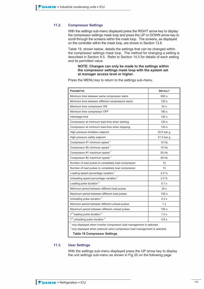
��������� ����������������������
������������������ ���
11.2. Compressor Settings
With the settings sub-menu displayed press the RIGHT arrow key to display the compressor settings mask loop and press the UP or DOWN arrow key to scroll through the screens within the mask loop. The screens, as displayed on the controller within the mask loop, are shown in Section 13.8.
Table 19, shown below, details the settings that can be changed within the compressor settings mask loop. The method for changing a setting is described in Section 8.5. Refer to Section 14.5 for details of each setting and its permitted value.
NOTE: Changes can only be made to the settings within the compressor settings mask loop with the system set at manager access level or higher.
Press the MENU key to return to the settings sub-menu.
PARAMETER DEFAULT
Minimum time between same compressor starts 600 s
Minimum time between different compressors starts 120 s
Minimum time compressor ON 30 s
Minimum time compressor OFF 180 s
Interstage time 120 s
Compressor at minimum load time when starting 120 s
Compressor at minimum load time when stopping 120 s
High pressure limitation setpoint 20.5 bar g
High pressure safety setpoint 21.5 bar g
Compressor #1 minimum speed 1 10 Hz
Compressor #2 minimum speed 1 10 Hz
Compressor #1 maximum speed 1 50 Hz
Compressor #2 maximum speed 1 50 Hz
Number of load pulses to completely load compressor 10
Number of load pulses to completely load compressor 10
Loading speed percentage variation 1 2.0 %
Unloading speed percentage variation 1 2.0 %
Loading pulse duration 2 0.1 s
Minimum period between different load pulses 30 s
Maximum period between different load pulses 150 s
Unloading pulse duration 2 0.3 s
Minimum period between different unload pulses 1 s
Maximum period between different unload pulses 150 s
1st loading pulse duration 2 1.0 s
1st unloading pulse duration 2 0.8 s 1 only displayed when inverter compressor load management is selected. 2 only displayed when solenoid valve compressor load management is selected.
Table 19 Compressor Settings
11.3. User Settings
With the settings sub-menu displayed press the UP arrow key to display the unit settings sub-menu as shown in Fig 20 on the following page.
ICU.pdf 141 26/01/2011 11:11:52
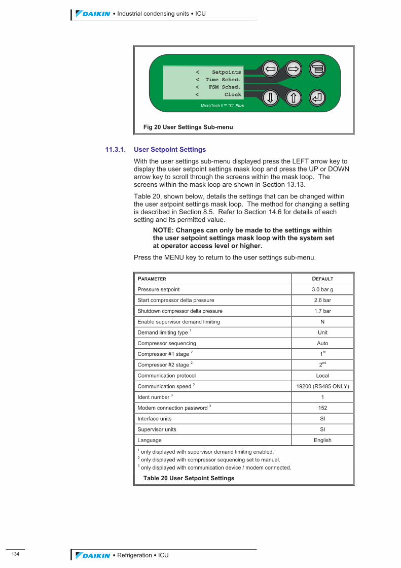
���
��������� ����������������������
������������������
Fig 20 User Settings Sub-menu
11.3.1. User Setpoint Settings
With the user settings sub-menu displayed press the LEFT arrow key to display the user setpoint settings mask loop and press the UP or DOWN arrow key to scroll through the screens within the mask loop. The screens within the mask loop are shown in Section 13.13.
Table 20, shown below, details the settings that can be changed within the user setpoint settings mask loop. The method for changing a setting is described in Section 8.5. Refer to Section 14.6 for details of each setting and its permitted value.
NOTE: Changes can only be made to the settings within the user setpoint settings mask loop with the system set at operator access level or higher.
Press the MENU key to return to the user settings sub-menu.
PARAMETER DEFAULT
Pressure setpoint 3.0 bar g
Start compressor delta pressure 2.6 bar
Shutdown compressor delta pressure 1.7 bar
Enable supervisor demand limiting N
Demand limiting type 1 Unit
Compressor sequencing Auto
Compressor #1 stage 2 1st
Compressor #2 stage 2 2nd
Communication protocol Local
Communication speed 3 19200 (RS485 ONLY)
Ident number 3 1
Modem connection password 3 152
Interface units SI
Supervisor units SI
Language English 1 only displayed with supervisor demand limiting enabled. 2 only displayed with compressor sequencing set to manual. 3 only displayed with communication device / modem connected.
Table 20 User Setpoint Settings
< Setpoints< Time Sched.< FSM Sched.< Clock
MicroTech II™ "C" Plus
ICU.pdf 142 26/01/2011 11:11:52
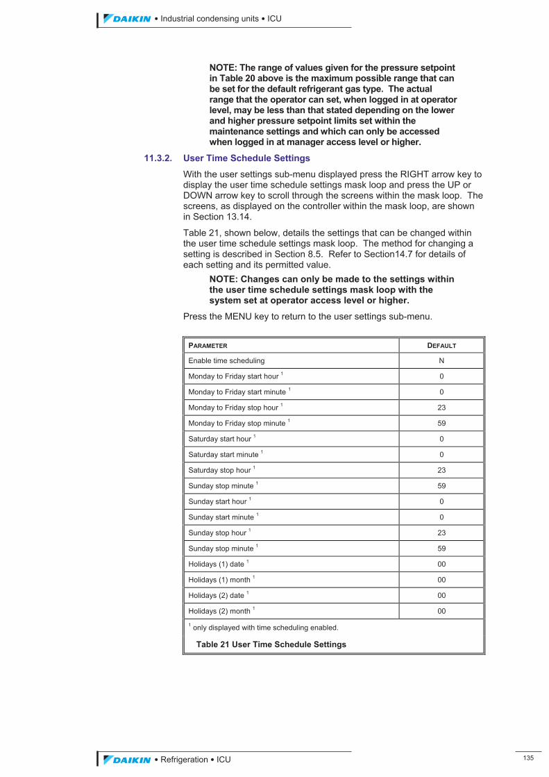
��������� ����������������������
������������������ ���
NOTE: The range of values given for the pressure setpoint in Table 20 above is the maximum possible range that can be set for the default refrigerant gas type. The actual range that the operator can set, when logged in at operator level, may be less than that stated depending on the lower and higher pressure setpoint limits set within the maintenance settings and which can only be accessed when logged in at manager access level or higher.
11.3.2. User Time Schedule Settings
With the user settings sub-menu displayed press the RIGHT arrow key to display the user time schedule settings mask loop and press the UP or DOWN arrow key to scroll through the screens within the mask loop. The screens, as displayed on the controller within the mask loop, are shown in Section 13.14.
Table 21, shown below, details the settings that can be changed within the user time schedule settings mask loop. The method for changing a setting is described in Section 8.5. Refer to Section14.7 for details of each setting and its permitted value.
NOTE: Changes can only be made to the settings within the user time schedule settings mask loop with the system set at operator access level or higher.
Press the MENU key to return to the user settings sub-menu.
PARAMETER DEFAULT
Enable time scheduling N
Monday to Friday start hour 1 0
Monday to Friday start minute 1 0
Monday to Friday stop hour 1 23
Monday to Friday stop minute 1 59
Saturday start hour 1 0
Saturday start minute 1 0
Saturday stop hour 1 23
Sunday stop minute 1 59
Sunday start hour 1 0
Sunday start minute 1 0
Sunday stop hour 1 23
Sunday stop minute 1 59
Holidays (1) date 1 00
Holidays (1) month 1 00
Holidays (2) date 1 00
Holidays (2) month 1 00
1 only displayed with time scheduling enabled.
Table 21 User Time Schedule Settings
ICU.pdf 143 26/01/2011 11:11:53
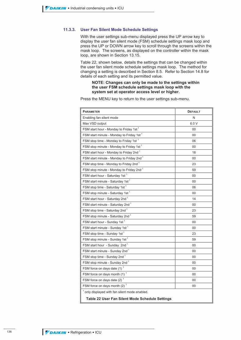
���
��������� ����������������������
������������������
11.3.3. User Fan Silent Mode Schedule Settings
With the user settings sub-menu displayed press the UP arrow key to display the user fan silent mode (FSM) schedule settings mask loop and press the UP or DOWN arrow key to scroll through the screens within the mask loop. The screens, as displayed on the controller within the mask loop, are shown in Section 13.15.
Table 22, shown below, details the settings that can be changed within the user fan silent mode schedule settings mask loop. The method for changing a setting is described in Section 8.5. Refer to Section 14.8 for details of each setting and its permitted value.
NOTE: Changes can only be made to the settings within the user FSM schedule settings mask loop with the system set at operator access level or higher.
Press the MENU key to return to the user settings sub-menu.
PARAMETER DEFAULT
Enabling fan silent mode N
Max VSD output 6.0 V
FSM start hour - Monday to Friday 1st 1 00
FSM start minute - Monday to Friday 1st 1 00
FSM stop time - Monday to Friday 1st 1 06
FSM stop minute - Monday to Friday 1st 1 00
FSM start hour - Monday to Friday 2nd 1 18
FSM start minute - Monday to Friday 2nd 1 00
FSM stop time - Monday to Friday 2nd 1 23
FSM stop minute - Monday to Friday 2nd 1 59
FSM start hour - Saturday 1st 1 00
FSM start minute - Saturday 1st 1 00
FSM stop time - Saturday 1st 1 06
FSM stop minute - Saturday 1st 1 00
FSM start hour - Saturday 2nd 1 14
FSM start minute - Saturday 2nd 1 00
FSM stop time - Saturday 2nd 1 23
FSM stop minute - Saturday 2nd 1 59
FSM start hour - Sunday 1st 1 00
FSM start minute - Sunday 1st 1 00
FSM stop time - Sunday 1st 1 23
FSM stop minute - Sunday 1st 1 59
FSM start hour - Sunday 2nd 1 00
FSM start minute - Sunday 2nd 1 00
FSM stop time - Sunday 2nd 1 00
FSM stop minute - Sunday 2nd 1 00
FSM force on days date (1) 1 00
FSM force on days month (1) 1 00
FSM force on days date (2) 1 00
FSM force on days month (2) 1 00 1 only displayed with fan silent mode enabled.
Table 22 User Fan Silent Mode Schedule Settings
ICU.pdf 144 26/01/2011 11:11:53
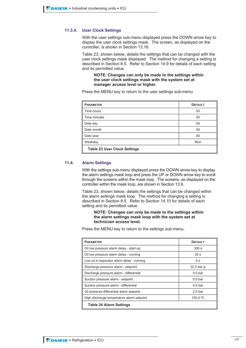
��������� ����������������������
������������������ ���
11.3.4. User Clock Settings
With the user settings sub-menu displayed press the DOWN arrow key to display the user clock settings mask. The screen, as displayed on the controller, is shown in Section 13.16.
Table 23, shown below, details the settings that can be changed with the user clock settings mask displayed. The method for changing a setting is described in Section 8.5. Refer to Section 14.9 for details of each setting and its permitted value.
NOTE: Changes can only be made to the settings within the user clock settings mask with the system set at manager access level or higher.
Press the MENU key to return to the user settings sub-menu.
PARAMETER DEFAULT
Time hours 00
Time minutes 00
Date day 00
Date month 00
Date year 00
Weekday Mon
Table 23 User Clock Settings
11.4. Alarm Settings
With the settings sub-menu displayed press the DOWN arrow key to display the alarm settings mask loop and press the UP or DOWN arrow key to scroll through the screens within the mask loop. The screens, as displayed on the controller within the mask loop, are shown in Section 13.9.
Table 23, shown below, details the settings that can be changed within the alarm settings mask loop. The method for changing a setting is described in Section 8.5. Refer to Section 14.10 for details of each setting and its permitted value.
NOTE: Changes can only be made to the settings within the alarm settings mask loop with the system set at technician access level.
Press the MENU key to return to the settings sub-menu.
PARAMETER DEFAULT
Oil low pressure alarm delay - start-up 300 s
Oil low pressure alarm delay - running 30 s
Low oil in separator alarm delay - running 5 s
Discharge pressure alarm - setpoint 22.0 bar g
Discharge pressure alarm - differential 0.0 bar
Suction pressure alarm - setpoint 0.0 bar
Suction pressure alarm - differential 0.0 bar
Oil pressure differential alarm setpoint 2.5 bar
High discharge temperature alarm setpoint 100.0 ºC
Table 24 Alarm Settings
ICU.pdf 145 26/01/2011 11:11:53
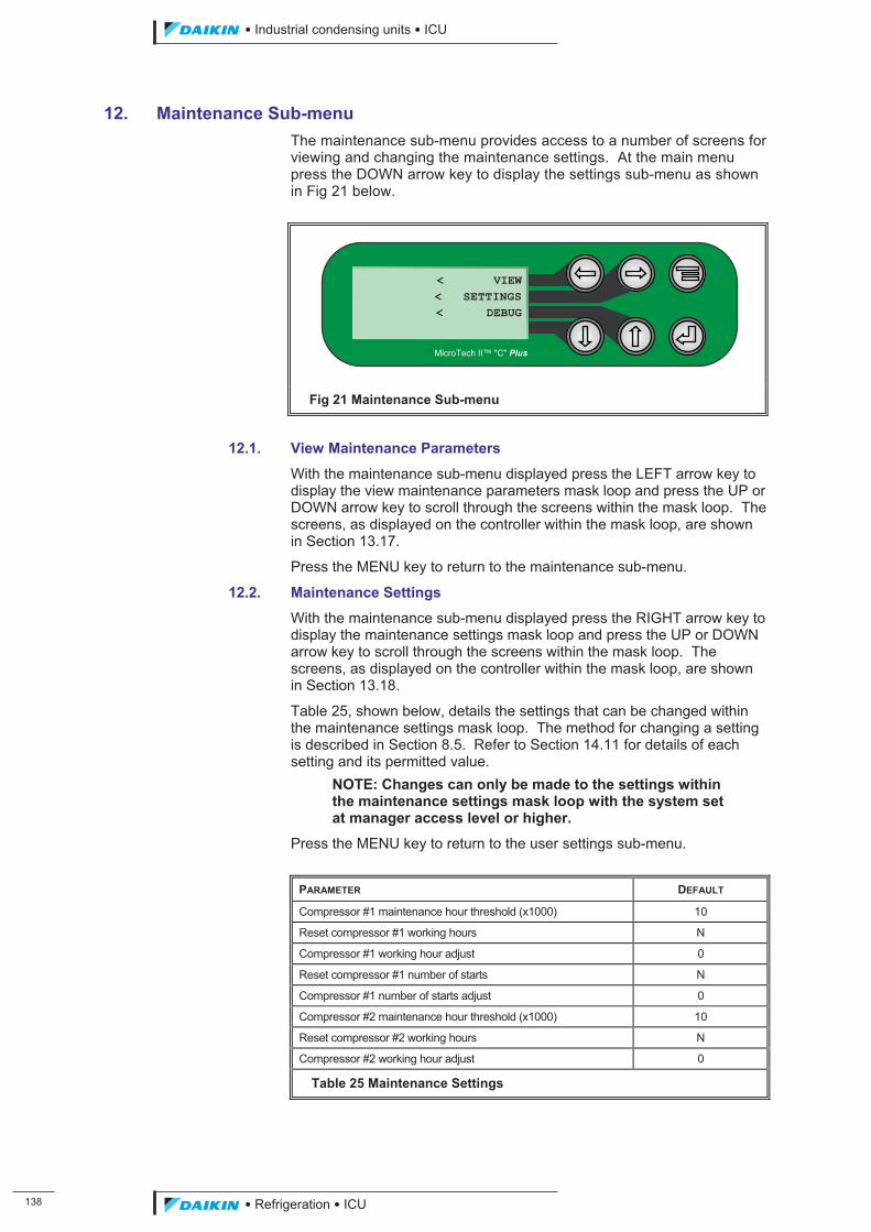
���
��������� ����������������������
������������������
12. Maintenance Sub-menu The maintenance sub-menu provides access to a number of screens for viewing and changing the maintenance settings. At the main menu press the DOWN arrow key to display the settings sub-menu as shown in Fig 21 below.
Fig 21 Maintenance Sub-menu
12.1. View Maintenance Parameters
With the maintenance sub-menu displayed press the LEFT arrow key to display the view maintenance parameters mask loop and press the UP or DOWN arrow key to scroll through the screens within the mask loop. The screens, as displayed on the controller within the mask loop, are shown in Section 13.17.
Press the MENU key to return to the maintenance sub-menu.
12.2. Maintenance Settings
With the maintenance sub-menu displayed press the RIGHT arrow key to display the maintenance settings mask loop and press the UP or DOWN arrow key to scroll through the screens within the mask loop. The screens, as displayed on the controller within the mask loop, are shown in Section 13.18.
Table 25, shown below, details the settings that can be changed within the maintenance settings mask loop. The method for changing a setting is described in Section 8.5. Refer to Section 14.11 for details of each setting and its permitted value.
NOTE: Changes can only be made to the settings within the maintenance settings mask loop with the system set at manager access level or higher.
Press the MENU key to return to the user settings sub-menu.
PARAMETER DEFAULT
Compressor #1 maintenance hour threshold (x1000) 10
Reset compressor #1 working hours N
Compressor #1 working hour adjust 0
Reset compressor #1 number of starts N
Compressor #1 number of starts adjust 0
Compressor #2 maintenance hour threshold (x1000) 10
Reset compressor #2 working hours N
Compressor #2 working hour adjust 0
Table 25 Maintenance Settings
< VIEW< SETTINGS< DEBUG
MicroTech II™ "C" Plus
ICU.pdf 146 26/01/2011 11:11:53
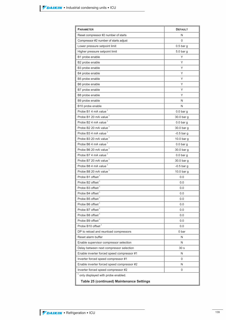
��������� ����������������������
������������������ ���
PARAMETER DEFAULT
Reset compressor #2 number of starts N
Compressor #2 number of starts adjust 0
Lower pressure setpoint limit 0.5 bar g
Higher pressure setpoint limit 5.0 bar g
B1 probe enable Y
B2 probe enable Y
B3 probe enable Y
B4 probe enable Y
B5 probe enable Y
B6 probe enable Y
B7 probe enable Y
B8 probe enable Y
B9 probe enable N
B10 probe enable N
Probe B1 4 mA value 1 0.0 bar g
Probe B1 20 mA value 1 30.0 bar g
Probe B2 4 mA value 1 0.0 bar g
Probe B2 20 mA value 1 30.0 bar g
Probe B3 4 mA value 1 -0.5 bar g
Probe B3 20 mA value 1 10.0 bar g
Probe B6 4 mA value 1 0.0 bar g
Probe B6 20 mA value 1 30.0 bar g
Probe B7 4 mA value 1 0.0 bar g
Probe B7 20 mA value 1 30.0 bar g
Probe B8 4 mA value 1 -0.5 bar g
Probe B8 20 mA value 1 10.0 bar g
Probe B1 offset 1 0.0
Probe B2 offset 1 0.0
Probe B3 offset 1 0.0
Probe B4 offset 1 0.0
Probe B5 offset 1 0.0
Probe B6 offset 1 0.0
Probe B7 offset 1 0.0
Probe B8 offset 1 0.0
Probe B9 offset 1 0.0
Probe B10 offset 1 0.0
DP to reload and reunload compressors 0 bar
Reset alarm buffer N
Enable supervisor compressor selection N
Delay between next compressor selection 30 s
Enable inverter forced speed compressor #1 N
Inverter forced speed compressor #1 0
Enable inverter forced speed compressor #2 N
Inverter forced speed compressor #2 0 1 only displayed with probe enabled.
Table 25 (continued) Maintenance Settings
ICU.pdf 147 26/01/2011 11:11:53
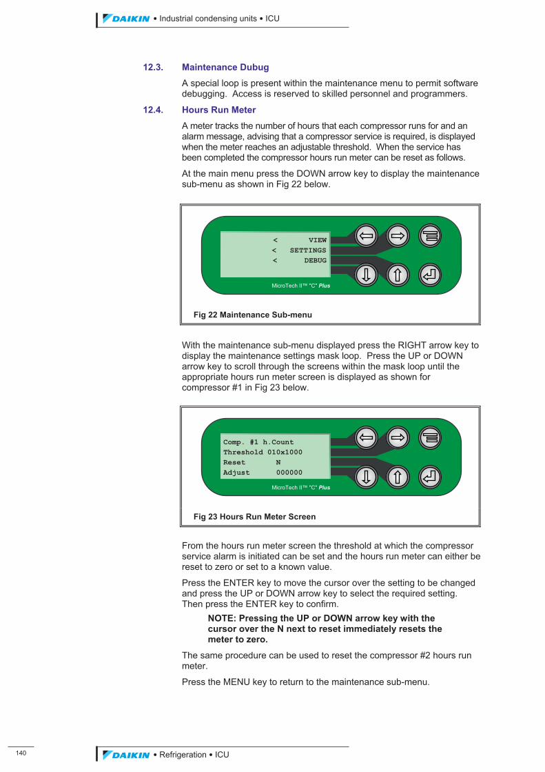
��
��������� ����������������������
������������������
12.3. Maintenance Dubug
A special loop is present within the maintenance menu to permit software debugging. Access is reserved to skilled personnel and programmers.
12.4. Hours Run Meter
A meter tracks the number of hours that each compressor runs for and an alarm message, advising that a compressor service is required, is displayed when the meter reaches an adjustable threshold. When the service has been completed the compressor hours run meter can be reset as follows.
At the main menu press the DOWN arrow key to display the maintenance sub-menu as shown in Fig 22 below.
Fig 22 Maintenance Sub-menu
With the maintenance sub-menu displayed press the RIGHT arrow key to display the maintenance settings mask loop. Press the UP or DOWN arrow key to scroll through the screens within the mask loop until the appropriate hours run meter screen is displayed as shown for compressor #1 in Fig 23 below.
Fig 23 Hours Run Meter Screen
From the hours run meter screen the threshold at which the compressor service alarm is initiated can be set and the hours run meter can either be reset to zero or set to a known value.
Press the ENTER key to move the cursor over the setting to be changed and press the UP or DOWN arrow key to select the required setting. Then press the ENTER key to confirm.
NOTE: Pressing the UP or DOWN arrow key with the cursor over the N next to reset immediately resets the meter to zero.
The same procedure can be used to reset the compressor #2 hours run meter.
Press the MENU key to return to the maintenance sub-menu.
Comp. #1 h.Count Threshold 010x1000 Reset N Adjust 000000
MicroTech II™ "C" Plus
< VIEW< SETTINGS< DEBUG
MicroTech II™ "C" Plus
ICU.pdf 148 26/01/2011 11:11:53
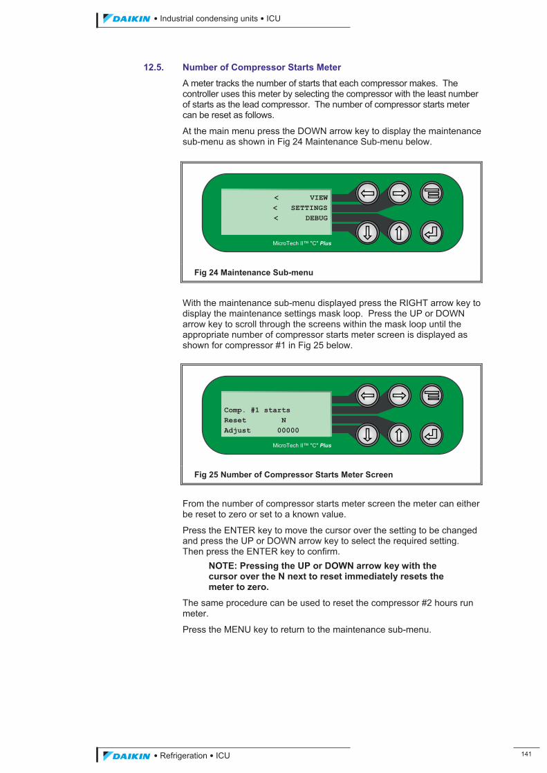
��������� ����������������������
������������������ ���
12.5. Number of Compressor Starts Meter
A meter tracks the number of starts that each compressor makes. The controller uses this meter by selecting the compressor with the least number of starts as the lead compressor. The number of compressor starts meter can be reset as follows.
At the main menu press the DOWN arrow key to display the maintenance sub-menu as shown in Fig 24 Maintenance Sub-menu below.
Fig 24 Maintenance Sub-menu
With the maintenance sub-menu displayed press the RIGHT arrow key to display the maintenance settings mask loop. Press the UP or DOWN arrow key to scroll through the screens within the mask loop until the appropriate number of compressor starts meter screen is displayed as shown for compressor #1 in Fig 25 below.
Fig 25 Number of Compressor Starts Meter Screen
From the number of compressor starts meter screen the meter can either be reset to zero or set to a known value.
Press the ENTER key to move the cursor over the setting to be changed and press the UP or DOWN arrow key to select the required setting. Then press the ENTER key to confirm.
NOTE: Pressing the UP or DOWN arrow key with the cursor over the N next to reset immediately resets the meter to zero.
The same procedure can be used to reset the compressor #2 hours run meter.
Press the MENU key to return to the maintenance sub-menu.
Comp. #1 starts Reset N Adjust 00000
MicroTech II™ "C" Plus
< VIEW< SETTINGS< DEBUG
MicroTech II™ "C" Plus
ICU.pdf 149 26/01/2011 11:11:53
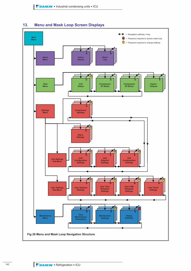
���
��������� ����������������������
������������������
13. Menu and Mask Loop Screen Displays
Fig 26 Menu and Mask Loop Navigation Structure
User Settings Sub-Menu
User Setpoint Settings
User Time Schedule Settings
User FSM Schedule Settings
User Clock
Settings
= Navigation pathway / loop.
= Password required to access mask loop.
= Password required to change settings.
View Menu
Unit Status
Compressor
#1 Status
Inputs / Outputs
Compressor
#2 Status
Main Menu
Alarm Menu
Active Alarms
Alarm Log
Settings
Menu
Alarm Settings
Compressor Settings
Unit Configuration
Settings
Unit Settings Sub-Menu
Unit Setpoint Settings
Unit Condensation
Settings
Maintenance
Menu
View Maintenance Parameters
Maintenance Settings
Debug Software
ICU.pdf 150 26/01/2011 11:11:53
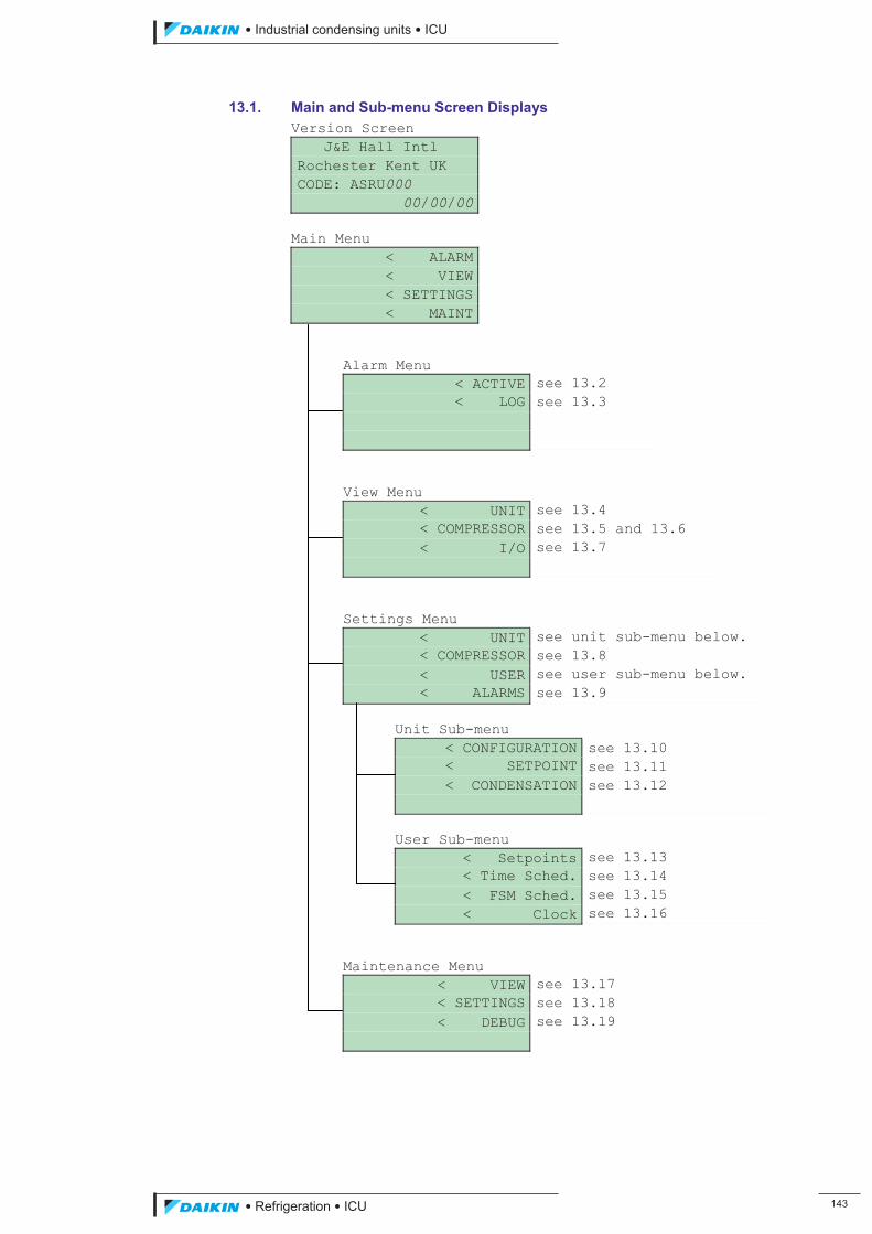
��������� ����������������������
������������������ ���
13.1. Main and Sub-menu Screen Displays Version Screen J&E Hall Intl Rochester Kent UK CODE: ASRU000 00/00/00 Main Menu < ALARM < VIEW < SETTINGS < MAINT
Alarm Menu < ACTIVE see 13.2 < LOG see 13.3 View Menu < UNIT see 13.4 < COMPRESSOR see 13.5 and 13.6 < I/O see 13.7 Settings Menu < UNIT see unit sub-menu below. < COMPRESSOR see 13.8 < USER see user sub-menu below. < ALARMS see 13.9
Unit Sub-menu < CONFIGURATION see 13.10 < SETPOINT see 13.11 < CONDENSATION see 13.12 User Sub-menu < Setpoints see 13.13 < Time Sched. see 13.14 < FSM Sched. see 13.15 < Clock see 13.16
Maintenance Menu < VIEW see 13.17 < SETTINGS see 13.18 < DEBUG see 13.19
ICU.pdf 151 26/01/2011 11:11:53
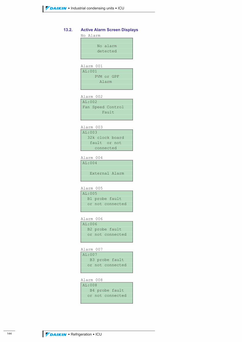
���
��������� ����������������������
������������������
13.2. Active Alarm Screen Displays No Alarm No alarm detected Alarm 001 AL:001 PVM or GPF Alarm Alarm 002 AL:002 Fan Speed Control Fault Alarm 003 AL:003 32k clock board fault or not connected Alarm 004 AL:004 External Alarm Alarm 005 AL:005 B1 probe fault or not connected Alarm 006 AL:006 B2 probe fault or not connected Alarm 007 AL:007 B3 probe fault or not connected Alarm 008 AL:008 B4 probe fault or not connected
ICU.pdf 152 26/01/2011 11:11:54
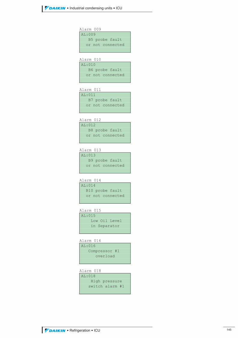
��������� ����������������������
������������������ ���
Alarm 009 AL:009 B5 probe fault or not connected Alarm 010 AL:010 B6 probe fault or not connected Alarm 011 AL:011 B7 probe fault or not connected Alarm 012 AL:012 B8 probe fault or not connected Alarm 013 AL:013 B9 probe fault or not connected Alarm 014 AL:014 B10 probe fault or not connected Alarm 015 AL:015 Low Oil Level in Separator Alarm 016 AL:016 Compressor #1 overload Alarm 018 AL:018 High pressure switch alarm #1
ICU.pdf 153 26/01/2011 11:11:54
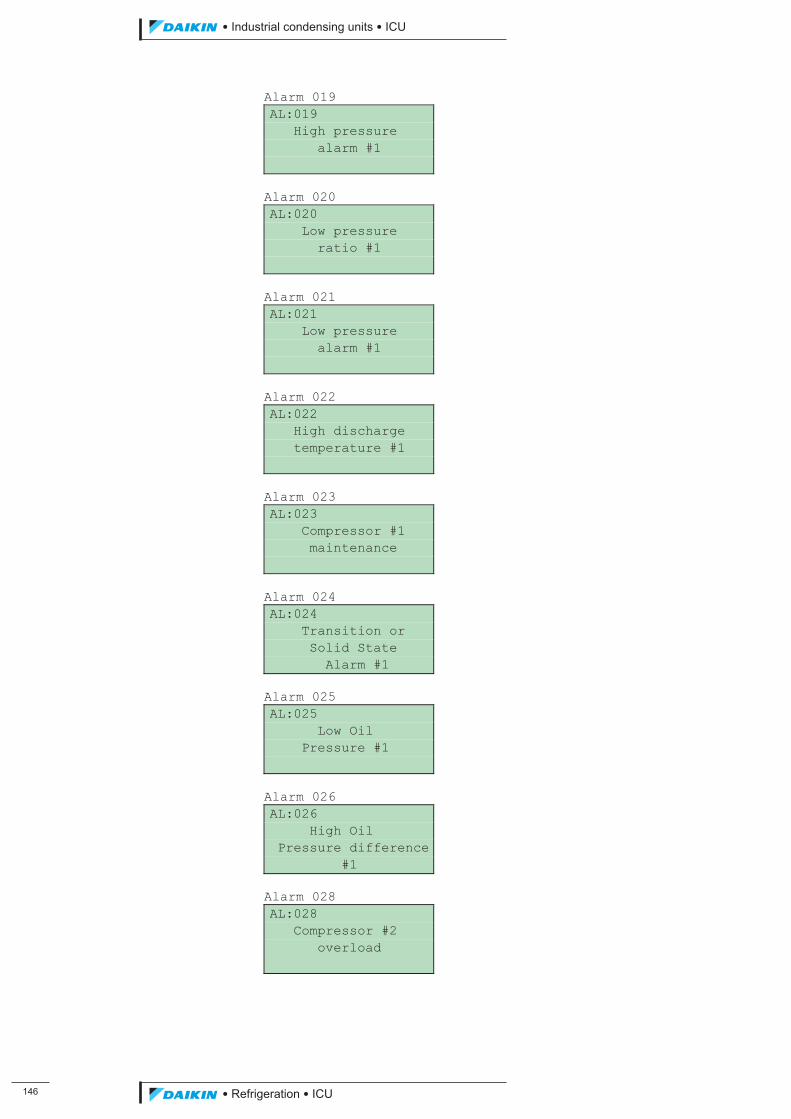
���
��������� ����������������������
������������������
Alarm 019 AL:019 High pressure alarm #1 Alarm 020 AL:020 Low pressure ratio #1 Alarm 021 AL:021 Low pressure alarm #1 Alarm 022 AL:022 High discharge temperature #1 Alarm 023 AL:023 Compressor #1 maintenance Alarm 024 AL:024 Transition or Solid State Alarm #1 Alarm 025 AL:025 Low Oil Pressure #1 Alarm 026 AL:026 High Oil Pressure difference #1 Alarm 028 AL:028 Compressor #2 overload
ICU.pdf 154 26/01/2011 11:11:54
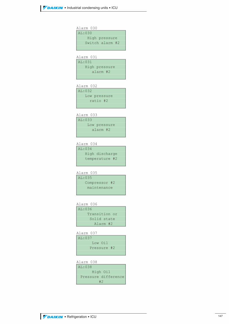
��������� ����������������������
������������������ ���
Alarm 030 AL:030 High pressure Switch alarm #2 Alarm 031 AL:031 High pressure alarm #2 Alarm 032 AL:032 Low pressure ratio #2 Alarm 033 AL:033 Low pressure alarm #2 Alarm 034 AL:034 High discharge temperature #2 Alarm 035 AL:035 Compressor #2 maintenance
Alarm 036 AL:036 Transition or Solid state Alarm #2 Alarm 037 AL:037 Low Oil Pressure #2 Alarm 038 AL:038 High Oil Pressure difference #2
ICU.pdf 155 26/01/2011 11:11:54
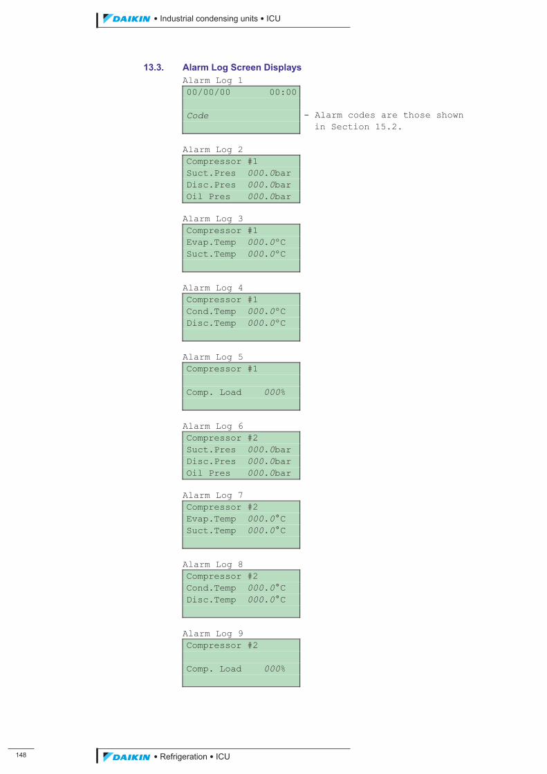
���
��������� ����������������������
������������������
13.3. Alarm Log Screen Displays Alarm Log 1 00/00/00 00:00 Code - Alarm codes are those shown in Section 15.2. Alarm Log 2 Compressor #1 Suct.Pres 000.0bar Disc.Pres 000.0bar Oil Pres 000.0bar Alarm Log 3 Compressor #1 Evap.Temp 000.0ºC Suct.Temp 000.0ºC Alarm Log 4 Compressor #1 Cond.Temp 000.0ºC Disc.Temp 000.0ºC Alarm Log 5 Compressor #1 Comp. Load 000% Alarm Log 6 Compressor #2 Suct.Pres 000.0bar Disc.Pres 000.0bar Oil Pres 000.0bar Alarm Log 7 Compressor #2 Evap.Temp 000.0°C Suct.Temp 000.0°C Alarm Log 8 Compressor #2 Cond.Temp 000.0°C Disc.Temp 000.0°C Alarm Log 9 Compressor #2 Comp. Load 000%
ICU.pdf 156 26/01/2011 11:11:54
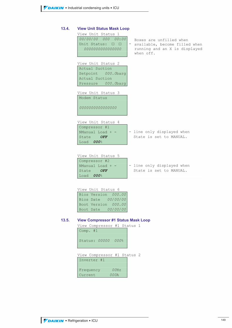
��������� ����������������������
������������������ ���
13.4. View Unit Status Mask Loop View Unit Status 1 00/00/00 000 00:00 Boxes are unfilled when
available, become filled when running and an X is displayed when off.
Unit Status: � � - 0000000000000000 View Unit Status 2 Actual Suction Setpoint 000.0bargActual Suction Pressure 000.0barg View Unit Status 3 Modem Status 0000000000000000 View Unit Status 4 Compressor #1 NManual Load + - - line only displayed when State OFF State is set to MANUAL. Load 000% View Unit Status 5 Compressor #2 NManual Load + - - line only displayed when State OFF State is set to MANUAL. Load 000% View Unit Status 6 Bios Version 000.00Bios Date 00/00/00Boot Version 000.00Boot Date 00/00/00
13.5. View Compressor #1 Status Mask Loop View Compressor #1 Status 1 Comp. #1 Status: 00000 000% View Compressor #1 Status 2 Inverter #1 Frequency 00Hz Current 000A
ICU.pdf 157 26/01/2011 11:11:54
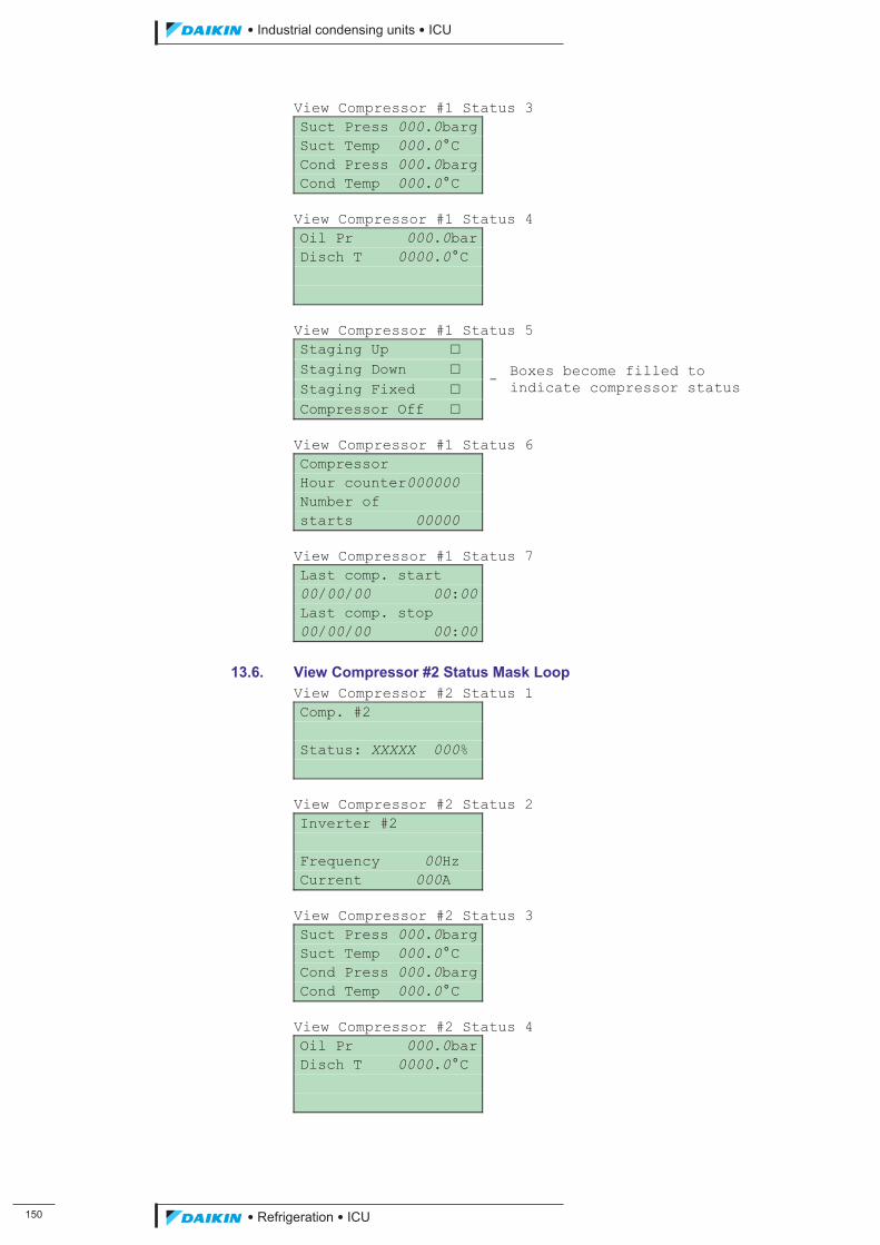
��
��������� ����������������������
������������������
View Compressor #1 Status 3 Suct Press 000.0bargSuct Temp 000.0°C Cond Press 000.0bargCond Temp 000.0°C View Compressor #1 Status 4 Oil Pr 000.0barDisch T 0000.0°C View Compressor #1 Status 5 Staging Up �
- Boxes become filled to indicate compressor status
Staging Down � Staging Fixed � Compressor Off � View Compressor #1 Status 6 Compressor Hour counter000000 Number of starts 00000 View Compressor #1 Status 7 Last comp. start 00/00/00 00:00Last comp. stop 00/00/00 00:00
13.6. View Compressor #2 Status Mask Loop View Compressor #2 Status 1 Comp. #2 Status: XXXXX 000% View Compressor #2 Status 2 Inverter #2 Frequency 00Hz Current 000A View Compressor #2 Status 3 Suct Press 000.0bargSuct Temp 000.0°C Cond Press 000.0bargCond Temp 000.0°C View Compressor #2 Status 4 Oil Pr 000.0barDisch T 0000.0°C
ICU.pdf 158 26/01/2011 11:11:54
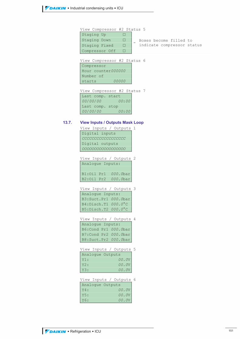
��������� ����������������������
������������������ ���
View Compressor #2 Status 5 Staging Up �
- Boxes become filled to indicate compressor status
Staging Down � Staging Fixed � Compressor Off � View Compressor #2 Status 6 Compressor Hour counter000000 Number of starts 00000 View Compressor #2 Status 7 Last comp. start 00/00/00 00:00Last comp. stop 00/00/00 00:00
13.7. View Inputs / Outputs Mask Loop View Inputs / Outputs 1 Digital inputs CCCCCCCCCCCCCCCCCC Digital outputs OOOOOOOOOOOOOOOOOO View Inputs / Outputs 2 Analogue Inputs: B1:Oil Pr1 000.0barB2:Oil Pr2 000.0bar View Inputs / Outputs 3 Analogue Inputs: B3:Suct.Pr1 000.0barB4:Disch.T1 000.0°C B5:Disch.T2 000.0°C View Inputs / Outputs 4 Analogue Inputs: B6:Cond Pr1 000.0barB7:Cond Pr2 000.0barB8:Suct.Pr2 000.0bar View Inputs / Outputs 5 Analogue Outputs Y1: 00.0VY2: 00.0VY3: 00.0V View Inputs / Outputs 6 Analogue Outputs Y4: 00.0VY5: 00.0VY6: 00.0V
ICU.pdf 159 26/01/2011 11:11:54
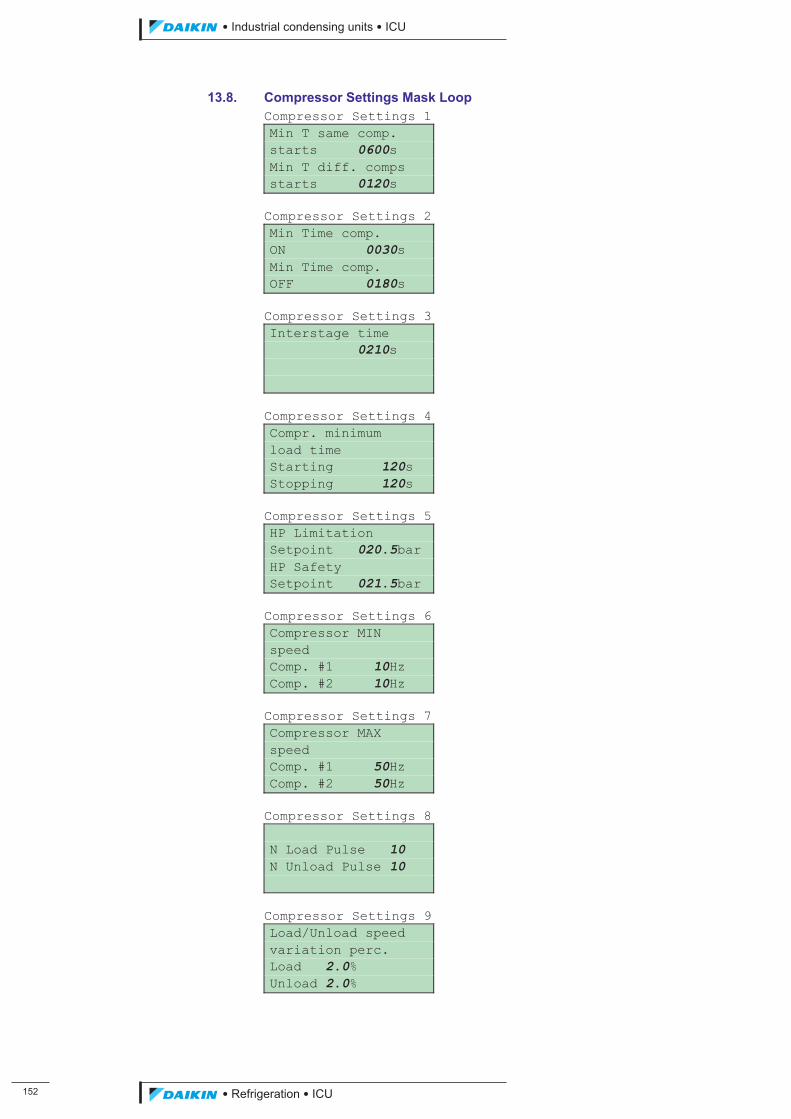
���
��������� ����������������������
������������������
13.8. Compressor Settings Mask Loop Compressor Settings 1 Min T same comp. starts 0600s Min T diff. comps starts 0120s Compressor Settings 2 Min Time comp. ON 0030s Min Time comp. OFF 0180s Compressor Settings 3 Interstage time 0210s Compressor Settings 4 Compr. minimum load time Starting 120s Stopping 120s Compressor Settings 5 HP Limitation Setpoint 020.5bar HP Safety Setpoint 021.5bar Compressor Settings 6 Compressor MIN speed Comp. #1 10Hz Comp. #2 10Hz Compressor Settings 7 Compressor MAX speed Comp. #1 50Hz Comp. #2 50Hz Compressor Settings 8 N Load Pulse 10 N Unload Pulse 10 Compressor Settings 9 Load/Unload speed variation perc. Load 2.0% Unload 2.0%
ICU.pdf 160 26/01/2011 11:11:54
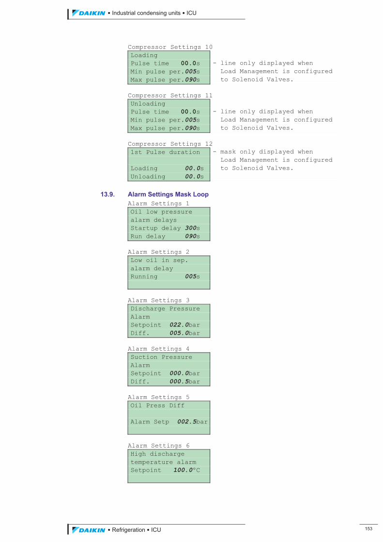
��������� ����������������������
������������������ ���
Compressor Settings 10 Loading Pulse time 00.0s - line only displayed when Min pulse per.005s Load Management is configured Max pulse per.090s to Solenoid Valves. Compressor Settings 11 Unloading Pulse time 00.0s - line only displayed when Min pulse per.005s Load Management is configured Max pulse per.090s to Solenoid Valves. Compressor Settings 12 1st Pulse duration - mask only displayed when Load Management is configured Loading 00.0s to Solenoid Valves. Unloading 00.0s
13.9. Alarm Settings Mask Loop Alarm Settings 1 Oil low pressure alarm delays Startup delay 300s Run delay 090s Alarm Settings 2 Low oil in sep. alarm delay Running 005s Alarm Settings 3 Discharge Pressure Alarm Setpoint 022.0bar Diff. 005.0bar Alarm Settings 4 Suction Pressure Alarm Setpoint 000.0bar Diff. 000.5bar Alarm Settings 5 Oil Press Diff Alarm Setp 002.5bar Alarm Settings 6 High discharge temperature alarm Setpoint 100.0ºC
ICU.pdf 161 26/01/2011 11:11:54
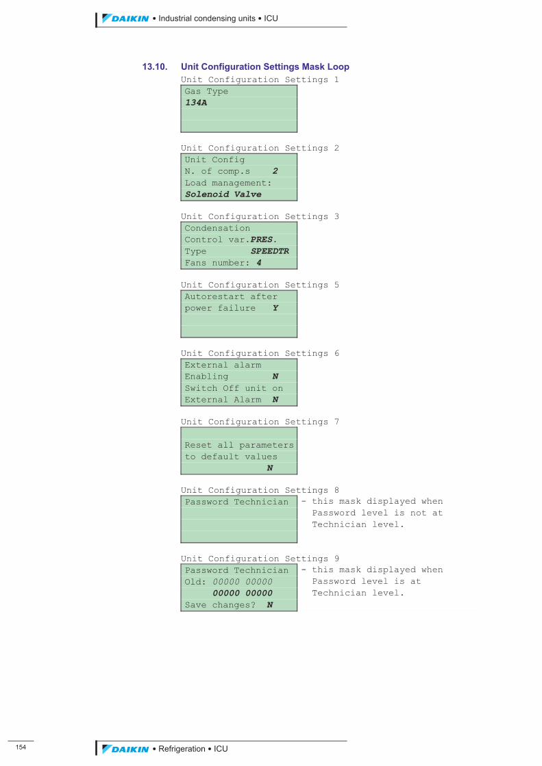
���
��������� ����������������������
������������������
13.10. Unit Configuration Settings Mask Loop Unit Configuration Settings 1 Gas Type 134A Unit Configuration Settings 2 Unit Config N. of comp.s 2 Load management: Solenoid Valve Unit Configuration Settings 3 Condensation Control var.PRES. Type SPEEDTR Fans number: 4 Unit Configuration Settings 5 Autorestart after power failure Y Unit Configuration Settings 6 External alarm Enabling N Switch Off unit on External Alarm N Unit Configuration Settings 7 Reset all parametersto default values N Unit Configuration Settings 8 Password Technician - this mask displayed when Password level is not at Technician level. Unit Configuration Settings 9 Password Technician - this mask displayed when Old: 00000 00000 Password level is at 00000 00000 Technician level. Save changes? N
ICU.pdf 162 26/01/2011 11:11:54
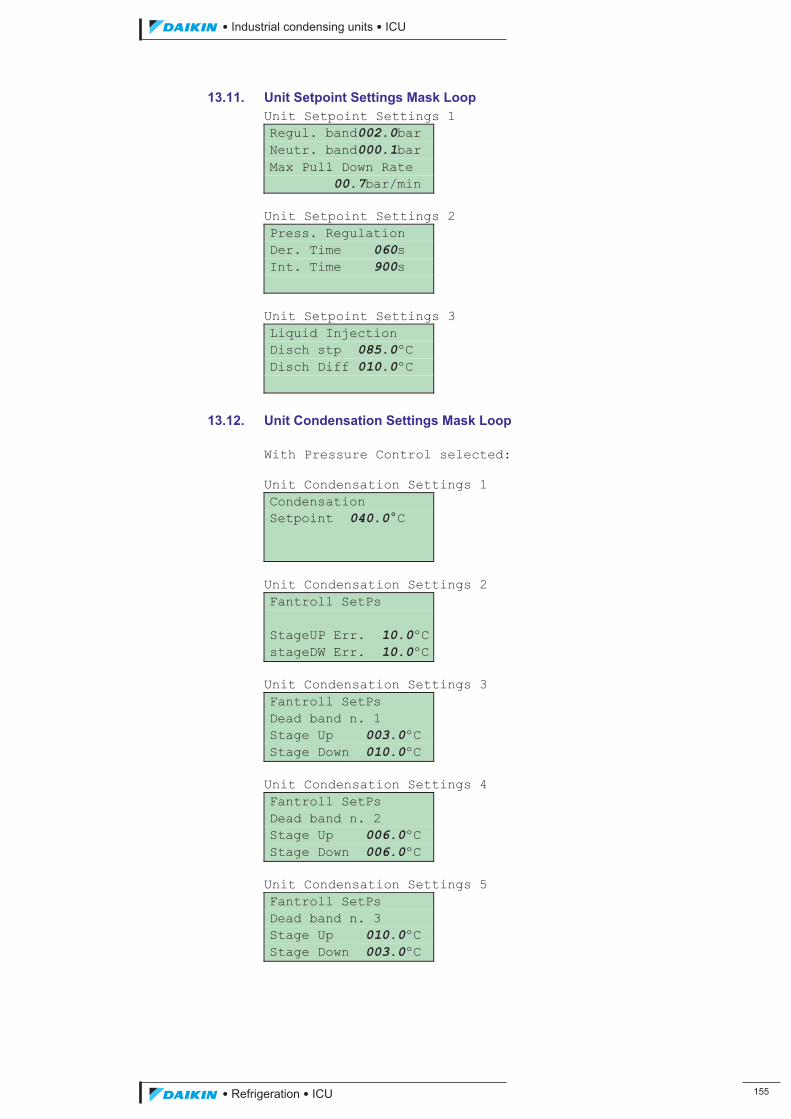
��������� ����������������������
������������������ ���
13.11. Unit Setpoint Settings Mask Loop Unit Setpoint Settings 1 Regul. band002.0bar Neutr. band000.1bar Max Pull Down Rate 00.7bar/min Unit Setpoint Settings 2 Press. Regulation Der. Time 060s Int. Time 900s Unit Setpoint Settings 3 Liquid Injection Disch stp 085.0ºC Disch Diff 010.0ºC
13.12. Unit Condensation Settings Mask Loop With Pressure Control selected: Unit Condensation Settings 1 Condensation Setpoint 040.0°C Unit Condensation Settings 2 Fantroll SetPs StageUP Err. 10.0ºCstageDW Err. 10.0ºC Unit Condensation Settings 3 Fantroll SetPs Dead band n. 1 Stage Up 003.0ºC Stage Down 010.0ºC Unit Condensation Settings 4 Fantroll SetPs Dead band n. 2 Stage Up 006.0ºC Stage Down 006.0ºC Unit Condensation Settings 5 Fantroll SetPs Dead band n. 3 Stage Up 010.0ºC Stage Down 003.0ºC
ICU.pdf 163 26/01/2011 11:11:55

���
��������� ����������������������
������������������
Unit Condensation Settings 6 Fantroll SetPs Dead band n. 4 Stage Up 010.0ºC Stage Down 002.0ºC Unit Condensation Settings 7 Fantroll SetPs Dead band n. 5 Stage Up 004.5ºC Stage Down 006.0ºC Unit Condensation Settings 8 Fantroll SetPs Dead band n. 6 Stage Up 004.5ºC Stage Down 006.0ºC Unit Condensation Settings 9 Fantroll SetPs Dead band n. 7 Stage Up 004.5ºC Stage Down 006.0ºC Unit Condensation Settings 10 Fantroll SetPs Dead band n. 8 Stage Up 004.5ºC Stage Down 006.0ºC Unit Condensation Settings 11 Fantroll SetPs Dead band n. 6 Stage Up 004.5ºC Stage Down 006.0ºC Unit Condensation Settings 12 VSD config. Max.speed 10.0V Min.speed 00.0V Speed up time 00s Unit Condensation Settings 13 VSD regulation parameters (1) Reg.Band 020.0ºC Neut.Band 001.0ºC Unit Condensation Settings 15 VSD Regulation parameters (2) Int. Time 150s Der. Time 001s
ICU.pdf 164 26/01/2011 11:11:55
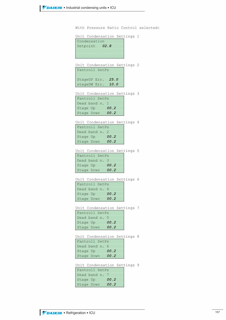
��������� ����������������������
������������������ ���
With Pressure Ratio Control selected: Unit Condensation Settings 1 Condensation Setpoint 02.8
Unit Condensation Settings 2 Fantroll SetPs StageUP Err. 25.0 stageDW Err. 10.0 Unit Condensation Settings 3 Fantroll SetPs Dead band n. 1 Stage Up 00.2 Stage Down 00.2 Unit Condensation Settings 4 Fantroll SetPs Dead band n. 2 Stage Up 00.2 Stage Down 00.2 Unit Condensation Settings 5 Fantroll SetPs Dead band n. 3 Stage Up 00.2 Stage Down 00.2 Unit Condensation Settings 6 Fantroll SetPs Dead band n. 4 Stage Up 00.2 Stage Down 00.2 Unit Condensation Settings 7 Fantroll SetPs Dead band n. 5 Stage Up 00.2 Stage Down 00.2 Unit Condensation Settings 8 Fantroll SetPs Dead band n. 6 Stage Up 00.2 Stage Down 00.2 Unit Condensation Settings 9 Fantroll SetPs Dead band n. 7 Stage Up 00.2 Stage Down 00.2
ICU.pdf 165 26/01/2011 11:11:55
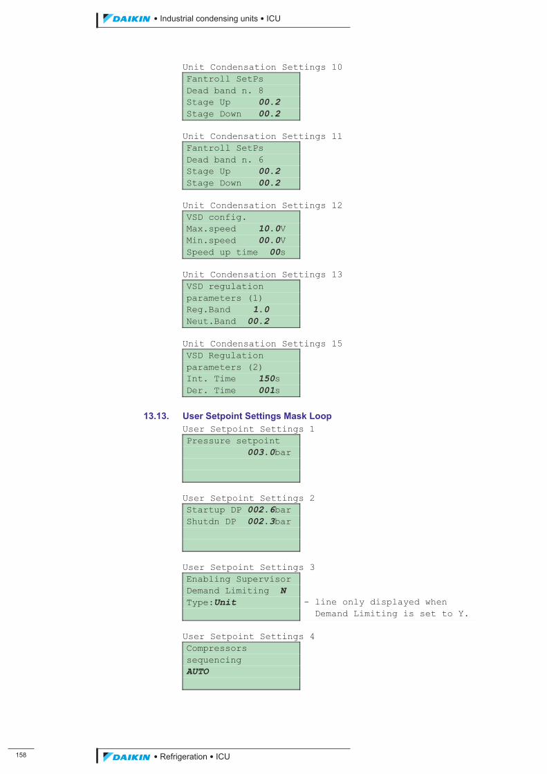
���
��������� ����������������������
������������������
Unit Condensation Settings 10 Fantroll SetPs Dead band n. 8 Stage Up 00.2 Stage Down 00.2 Unit Condensation Settings 11 Fantroll SetPs Dead band n. 6 Stage Up 00.2 Stage Down 00.2 Unit Condensation Settings 12 VSD config. Max.speed 10.0V Min.speed 00.0V Speed up time 00s Unit Condensation Settings 13 VSD regulation parameters (1) Reg.Band 1.0 Neut.Band 00.2 Unit Condensation Settings 15 VSD Regulation parameters (2) Int. Time 150s Der. Time 001s
13.13. User Setpoint Settings Mask Loop
User Setpoint Settings 1 Pressure setpoint 003.0bar User Setpoint Settings 2 Startup DP 002.6bar Shutdn DP 002.3bar User Setpoint Settings 3 Enabling Supervisor Demand Limiting N Type:Unit - line only displayed when Demand Limiting is set to Y. User Setpoint Settings 4 Compressors sequencing AUTO
ICU.pdf 166 26/01/2011 11:11:55
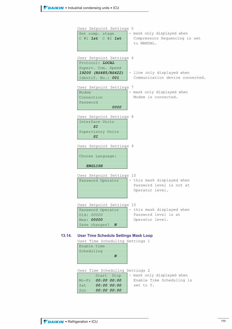
��������� ����������������������
������������������ ���
User Setpoint Settings 5 Set comp. stage - mask only displayed when C #1 1st C #2 1st Compressors Sequencing is set to MANUAL. User Setpoint Settings 6 Protocol: LOCAL Superv. Com. Speed 19200 (RS485/RS422) - line only displayed when Identif. No.: 001 Communication device connected. User Setpoint Settings 7 Modem - mask only displayed when Connection Modem is connected. Password 0000 User Setpoint Settings 8 Interface Units SI Supervisory Units SI User Setpoint Settings 9 Choose Language: ENGLISH User Setpoint Settings 10 Password Operator - this mask displayed when Password level is not at Operator level. User Setpoint Settings 10 Password Operator - this mask displayed when Old: 00000 Password level is at New: 00000 Operator level. Save changes? N
13.14. User Time Schedule Settings Mask Loop User Time Scheduling Settings 1 Enable time Scheduling N User Time Scheduling Settings 2 Start Stop - mask only displayed when Mo-Fr 00:00 00:00 Enable Time Scheduling is Sat 00:00 00:00 set to Y. Sun 00:00 00:00
ICU.pdf 167 26/01/2011 11:11:55
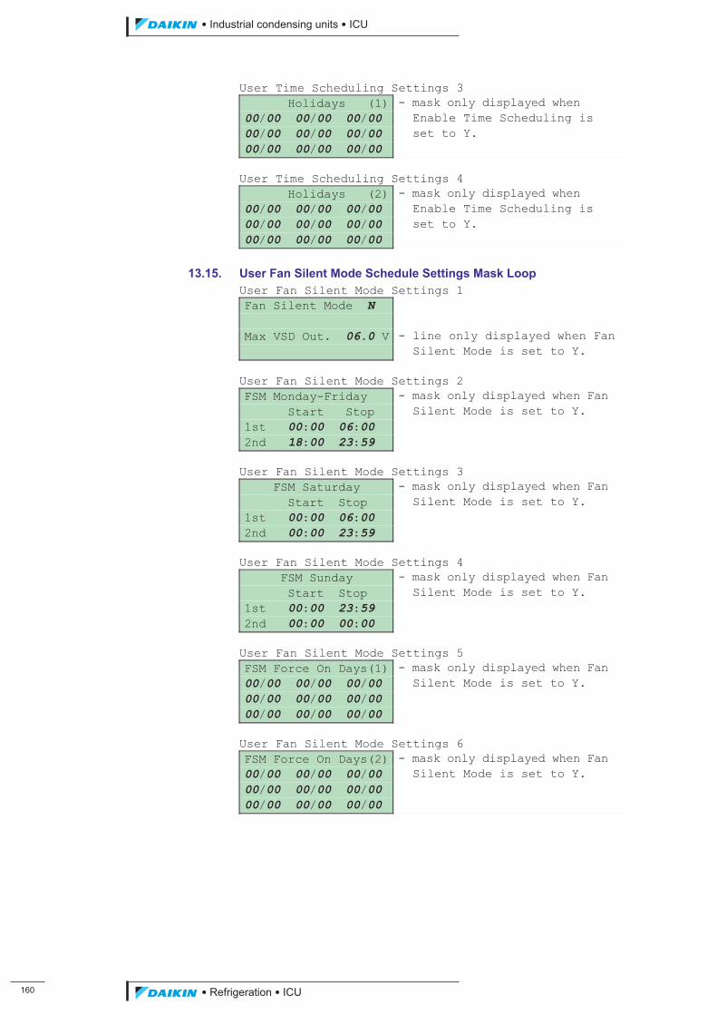
��
��������� ����������������������
������������������
User Time Scheduling Settings 3 Holidays (1) - mask only displayed when 00/00 00/00 00/00 Enable Time Scheduling is 00/00 00/00 00/00 set to Y. 00/00 00/00 00/00 User Time Scheduling Settings 4 Holidays (2) - mask only displayed when 00/00 00/00 00/00 Enable Time Scheduling is 00/00 00/00 00/00 set to Y. 00/00 00/00 00/00
13.15. User Fan Silent Mode Schedule Settings Mask Loop User Fan Silent Mode Settings 1 Fan Silent Mode N Max VSD Out. 06.0 V - line only displayed when Fan Silent Mode is set to Y. User Fan Silent Mode Settings 2 FSM Monday-Friday - mask only displayed when Fan Start Stop Silent Mode is set to Y. 1st 00:00 06:00 2nd 18:00 23:59 User Fan Silent Mode Settings 3 FSM Saturday - mask only displayed when Fan Start Stop Silent Mode is set to Y. 1st 00:00 06:00 2nd 00:00 23:59 User Fan Silent Mode Settings 4 FSM Sunday - mask only displayed when Fan Start Stop Silent Mode is set to Y. 1st 00:00 23:59 2nd 00:00 00:00 User Fan Silent Mode Settings 5 FSM Force On Days(1) - mask only displayed when Fan 00/00 00/00 00/00 Silent Mode is set to Y. 00/00 00/00 00/00 00/00 00/00 00/00 User Fan Silent Mode Settings 6 FSM Force On Days(2) - mask only displayed when Fan 00/00 00/00 00/00 Silent Mode is set to Y. 00/00 00/00 00/00 00/00 00/00 00/00
ICU.pdf 168 26/01/2011 11:11:55
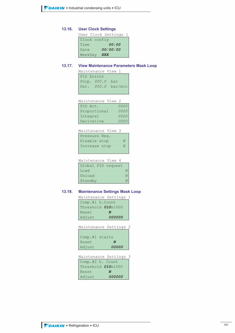
��������� ����������������������
������������������ ���
13.16. User Clock Settings User Clock Settings 1 Clock config Time 00:00 Date 00/00/00 WeekDay XXX
13.17. View Maintenance Parameters Mask Loop Maintenance View 1 PID Errors Prop. 000.0 bar Der. 000.0 bar/min Maintenance View 2 PID Act. 0000Proportional 0000Integral 0000Derivative 0000 Maintenance View 3 Pressure Reg. Disable stop N Increase stop N Maintenance View 4 Global PID request Load NUnload NStandby N
13.18. Maintenance Settings Mask Loop Maintenance Settings 1 Comp.#1 h.Count Threshold 010x1000 Reset N Adjust 000000 Maintenance Settings 2 Comp.#1 starts Reset N Adjust 00000 Maintenance Settings 3 Comp.#2 h. Count Threshold 010x1000 Reset N Adjust 000000
ICU.pdf 169 26/01/2011 11:11:55
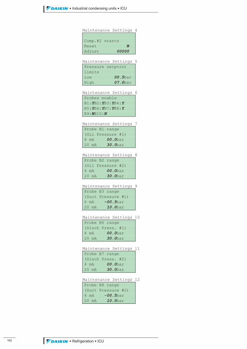
���
��������� ����������������������
������������������
Maintenance Settings 4 Comp.#2 starts Reset N Adjust 00000 Maintenance Settings 5 Pressure setpoint limits Low 00.5bar High 07.0bar Maintenance Settings 6 Probes enable B1:YB2:YB3:YB4:Y B5:YB6:YB7:YB8:Y B9:NB10:N Maintenance Settings 7 Probe B1 range (Oil Pressure #1) 4 mA 00.0bar 20 mA 30.0bar Maintenance Settings 8 Probe B2 range (Oil Pressure #2) 4 mA 00.0bar 20 mA 30.0bar Maintenance Settings 9 Probe B3 range (Suct Pressure #1) 4 mA -00.5bar 20 mA 10.0bar Maintenance Settings 10 Probe B6 range (Disch Press. #1) 4 mA 00.0bar 20 mA 30.0bar Maintenance Settings 11 Probe B7 range (Disch Press. #2) 4 mA 00.0bar 20 mA 30.0bar Maintenance Settings 12 Probe B8 range (Suct Pressure #2) 4 mA -00.5bar 20 mA 10.0bar
ICU.pdf 170 26/01/2011 11:11:55
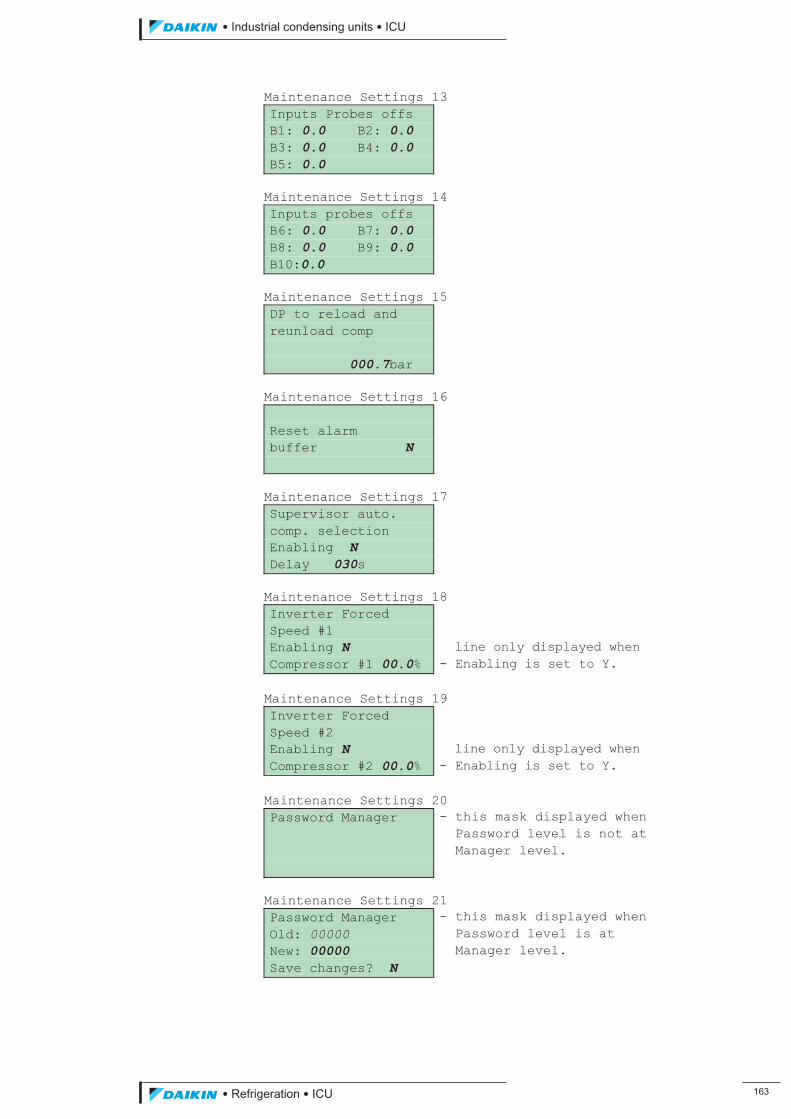
��������� ����������������������
������������������ ���
Maintenance Settings 13 Inputs Probes offs B1: 0.0 B2: 0.0 B3: 0.0 B4: 0.0 B5: 0.0 Maintenance Settings 14 Inputs probes offs B6: 0.0 B7: 0.0 B8: 0.0 B9: 0.0 B10:0.0 Maintenance Settings 15 DP to reload and reunload comp 000.7bar Maintenance Settings 16 Reset alarm buffer N Maintenance Settings 17 Supervisor auto. comp. selection Enabling N Delay 030s Maintenance Settings 18 Inverter Forced Speed #1 Enabling N line only displayed when Compressor #1 00.0% - Enabling is set to Y. Maintenance Settings 19 Inverter Forced Speed #2 Enabling N line only displayed when Compressor #2 00.0% - Enabling is set to Y. Maintenance Settings 20 Password Manager - this mask displayed when Password level is not at Manager level. Maintenance Settings 21 Password Manager - this mask displayed when Old: 00000 Password level is at New: 00000 Manager level. Save changes? N
ICU.pdf 171 26/01/2011 11:11:55
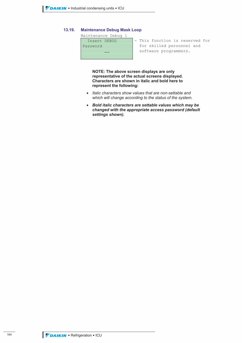
���
��������� ����������������������
������������������
13.19. Maintenance Debug Mask Loop Maintenance Debug 1 Insert DEBUG - This function is reserved for Password for skilled personnel and �� software programmers.
NOTE: The above screen displays are only representative of the actual screens displayed. Characters are shown in italic and bold here to represent the following:
� Italic characters show values that are non-settable and which will change according to the status of the system.
� Bold italic characters are settable values which may be changed with the appropriate access password (default settings shown).
ICU.pdf 172 26/01/2011 11:11:55
��������� ����������������������
������������������ ���
14. Configuration During commissioning the systems settings will need to be configured to suit the operating conditions and parameters of the refrigeration system. The following sections detail the settings that can be configured; refer to Section 8 User Interface for details of how to navigate through the menu structure and change settings.
A table is provided in Appendix 1 for recording the as-commissioned settings. It is essential that the settings are recorded so they may be re-entered into the controller if they become corrupted or are lost.
14.1. View Unit Status Settings
Compressor Capacity Control
Select the control type for controlling the compressor capacity: automatic, manual or off. Refer to Section 5.4.
14.2. Unit Configuration Settings
Refrigerant
Select the refrigerant type: R22, R134a, R404a, R407c, R410a, R507c, R290, R600, R600a, R717 or R744.
Number of Compressors
Select the number of compressors: 1 or 2.
Compressor Load Management
Select the method of compressor capacity modulation: solenoid valve or inverter. Refer to Section 5.5.
Condensation Control Variable
Select the variable to be used for controlling condensation: none, pressure or pressure ratio. Refer to Section 5.13.
Condensation Control Type
Select the method to be used for controlling condensation: variable speed drive, fantroll, speedtroll or fan modulation. Refer to Section 5.13.
Number of Fans
Select the number of condenser fans: 1 to 9 (select 9 if 10 fans fitted). Refer to Section 5.13.
Auto Restart after Power Failure
Automatically restart the system following a power outage: yes or no. Refer to Section 5.13.
External Alarm Enable
Enable use of a digital input for the indication of an external alarm: yes or no. Refer to Section 15.5.
Switch Off Unit on External Alarm
Stop the unit on receipt of the external alarm digital input: yes or no. Refer to Section 15.5.
Reset All Parameters to Default Value
Reset all parameters to the default value: yes or no. Refer to Section 14.12.
ICU.pdf 173 26/01/2011 11:11:55
���
��������� ����������������������
������������������
14.3. Unit Setpoint Settings
Regulation Band (units: bar)
Input the size of band, across the setpoint, within which proportional control takes place: 0.0 bar to 999.9 bar. Refer to section 5.4.2.
Neutral Band (units: bar)
Input the size of band, across the setpoint, within which no control action takes place: 0.0 bar to the value of the regulation band. Refer to section 5.4.2.
Maximum Pull-down Rate (units: bar / min)
Input the rate the suction pressure can approach the setpoint above which load action is inhibited: 0.2 bar / min to 99.9 bar / min. Refer to section 5.4.2.
Pressure Regulation Integral Time (units: second)
Input the integral action time: 0 to 999 seconds. Refer to section 5.4.2.
Pressure Regulation Derivative Time (units: seconds)
Input the derivative action time: 1 to 999 seconds. Refer to section 5.4.2.
Liquid Injection Discharge Setpoint (units: degrees Celsius)
Input the discharge temperature setpoint at which the liquid injection digital output signal is initiated: 0 ºC to 999.9 ºC. Refer to Section 5.14.
Liquid Injection Differential (units: degrees Celsius)
Input the temperature value that the discharge temperature must fall by, from the liquid injection discharge setpoint, before the liquid injection digital output signal is removed: 0 ºC to 999.9 ºC. Refer to Section 5.14.
14.4. Unit Condensation Settings NOTE: Only the settings applicable to the type of condensation control selected will be displayed.
14.4.1. Pressure Control
Condensation Setpoint (units: degrees Celsius)
Input the setpoint at which the saturated temperature at discharge pressure is required to be maintained: 0.0 °C to 999.9 °C. Refer to Section 4.0.
Stage-Up Error (units: degrees Celsius)
Input the required stage up error value: -99.9 °C to 99.9 °C. Refer to Section 5.13.
Stage-Down Error (units: degrees Celsius)
Input the required stage down error value: -99.9 °C to 99.9 °C. Refer to Section 5.13.
Stage-up Dead Band Numbers 1 to 9 (units: degrees Celsius)
Enter the value of the band above the setpoint before each fan stage is activated: 0.0 °C to 999.9 °C. Refer to Section 5.13.
Stage-down Dead Band Numbers 1 to 9 (units: degrees Celsius)
Enter the value of the band below the setpoint before each fan stage is deactivated: 0.0 °C to 999.9 °C. Refer to Section 5.13.
ICU.pdf 174 26/01/2011 11:11:56
��������� ����������������������
������������������ ���
VSD Max Speed (units: volt)
Input the output control voltage to run the condenser fans at maximum speed: 0.0 V to 10.0 V. Refer to Section 5.13.
VSD Min Speed (units: volt)
Input the output control voltage to run the condenser fans at minimum speed: 0.0 V to 10.0 V. Refer to Section 5.13.
VSD Speed-up Time (units: seconds)
Input the time period within which the condenser fan variable speed drive shall respond to a change in the output control voltage: 0 s to 99 s. Refer to Section 5.13.
VSD Regulation Band (units: degrees Celsius)
Input the size of band, across the setpoint, within which proportional control takes place: 0.0 °C to 99.9 °C. Refer to Section 5.13.
VSD Neutral Band (units: degrees Celsius)
Input the size of band, across the setpoint, within which no control action takes place: 0.0 ºC to VSD Regulation Band Value. Refer to Section 5.13.
VSD Integral Time (units: degrees Celsius)
Input the integral action time: 0 s to 999 s. Refer to Section 5.13.
VSD Derivative Time (units: seconds)
Input the derivative action time: 0 s to 999 s. Refer to Section 5.13.
14.4.2. Pressure Ratio Control
Condensation Setpoint (units: degrees Celsius)
Input the value at which the ratio between the suction pressure and discharge pressure is required to be maintained: 0.0 ºC to 999.9 ºC. Refer to Section 4.0.
Stage-up Error (units: degrees Celsius)
Input the required stage up error value: -99.9 ºC to 99.9 ºC. Refer to Section 5.13.
Stage-down Error (units: degrees Celsius)
Input the required stage down error value: -99.9 to 99.9. Refer to Section 5.13.
Stage-up Dead Band Numbers 1 to 9 (units: degrees Celsius)
Enter the value of the band above the setpoint before each fan stage is activated: 0.0 ºC to 999.9 ºC. Refer to Section 5.13.
Stage-down Dead Band Numbers 1 to 9 (units: degrees Celsius)
Enter the value of the band below the setpoint before each fan stage is deactivated: 0.0 ºC to 999.9 ºC. Refer to Section 5.13.
VSD Max Speed (units: volt)
Input the output control voltage to run the condenser fans at maximum speed: 0.0 V to 10.0 V. Refer to Section 5.13.
VSD Min Speed (units: volt)
Input the output control voltage to run the condenser fans at minimum speed: 0.0 V to 10.0 V. Refer to Section 5.13.
ICU.pdf 175 26/01/2011 11:11:56
���
��������� ����������������������
������������������
VSD Speed-up Time (units: seconds)
Input the time period within which the condenser fan variable speed drive shall respond to a change in the output control voltage: 0 s to 99 s. Refer to Section 5.13.
VSD Regulation Band
Input the size of band, across the setpoint, within which proportional control takes place: 0.0 to 99.9. Refer to Section 5.13.
VSD Neutral Band
Input the size of band, across the setpoint, within which no control action takes place: 0.0 to VSD Regulation Band. Refer to Section 5.13.
VSD Integral Time (units: seconds)
Input the integral action time: 0 s to 999 s. Refer to Section 5.13.
VSD Derivative Time (units: seconds)
Input the derivative action time: 0 s to 999 s. Refer to Section 5.13.
14.5. Compressor Settings
Minimum Time Between Same Compressor Starts (units: seconds)
Input the minimum time period allowed between two starts of the same compressor: 0 s to 9999 s. Refer to Section 5.7.
Minimum Time Between Different Compressors Starts (units: seconds)
Input the minimum time period allowed between starts of two different compressors: 0 s to 9999 s. Refer to Section 5.7.
Minimum Time Compressor ON (units: seconds)
Input the minimum time a compressor shall run: 0 s to 9999 s. Refer to Section 5.7.
Minimum Time Compressor OFF (units: seconds)
Input the minimum time a compressor must remain stopped before being allowed to run: 0 s to 9999 s. Refer to Section 5.7.
Interstage Time (units: seconds)
Input the time between the lead and lag compressors starting: 0 s to 9999 s. Refer to Section 5.6.
Compressor at Minimum Load Time When Starting (units: seconds)
Input the time period that the compressor will remain at minimum load for when starting: 0 s to 999 s. Refer to Section 5.7.
Compressor at Minimum Load Time When Stopping (units: seconds)
Input the time period that the compressor will remain at minimum load for when stopping: 0 s to 999 s. Refer to Section 5.7.
High Pressure Limitation Setpoint (units: bar g)
Input the setpoint at which compressor loading shall be inhibited: 0.0 bar g to 999.9 bar g. Refer to Section 5.9.1.
High Pressure Safety Setpoint (units: bar g)
Input the setpoint at which compressor unloading shall be initiated: 0.0 bar g to 999.9 bar g. Refer to Section 5.9.1.
ICU.pdf 176 26/01/2011 11:11:56
��������� ����������������������
������������������ ���
Compressor #1 Minimum Speed (units: hertz)
Input the frequency to run compressor #1 at minimum speed: 0 Hz to 99 Hz. Refer to Section 5.5.2.
Compressor #2 Minimum Speed (units: hertz)
Input the frequency to run compressor #2 at minimum speed: 0 Hz to 99 Hz. Refer to Section 5.5.2.
Compressor #1 Maximum Speed (units: hertz)
Input the frequency to run compressor #1 at maximum speed: compressor minimum speed to 99 Hz. Refer to Section 5.5.2.
Compressor #2 Maximum Speed (units: hertz)
Input the frequency to run compressor #2 at maximum speed: compressor minimum speed to 99 Hz. Refer to Section 5.5.2.
Number of Load Pulses
Input the number of load pulses required to take the compressor from minimum load to maximum load: 0 to 99. Refer to Section 5.4.2.
Number of Unload Pulses
Input the number of unload pulses required to take the compressor from minimum load to maximum load: 0 to 99. Refer to Section 5.4.2.
Loading Speed Percentage Variation
Input the percentage that compressor capacity is increased at each stage or with each press of the UP arrow key: 0.0 % to 9.9 %. Refer to Section 5.4.2.
Unloading Speed Percentage Variation
Input the percentage that compressor capacity is decreased at each stage or with each press of the DOWN arrow key: 0.0 % to 9.9 %. Refer to Section 5.4.2.
Loading Pulse Duration (units: seconds)
Input the time period for each load pulse: 0.0 s to 99.9 s. Refer to Section 5.4.2.
Minimum Period between Different Load Pulses (units: seconds)
Input the minimum time period allowed between two load pulses: 0 s to 999 s. Refer to Section 5.4.2.
Maximum Period between Different Load Pulses (units: seconds)
Input the maximum time period allowed between two load pulses: 0 s to 999 s. Refer to Section 5.4.2.
Unloading Pulse Duration (units: seconds)
Input the time period for each unload pulse: 0.0 s to 99.9 s. Refer to Section 5.4.2.
Minimum Period between Different Unload Pulses (units: seconds)
Input the minimum time period allowed between two unload pulses: 0 s to 999 s. Refer to Section 5.4.2.
Maximum Period between Different Unload Pulses (units: seconds)
Input the maximum time period allowed between two unload pulses: 0 s to 999 s. Refer to Section 5.4.2.
ICU.pdf 177 26/01/2011 11:11:56
��
��������� ����������������������
������������������
1st Loading Pulse Duration (units: seconds)
Input the time period for the first pulse at the beginning of a load cycle: 0.0 s to 99.9 s. Refer to Section 5.5.1.
1st Unloading Pulse Duration (units: seconds)
Input the time period for the first unloading pulse at the beginning of an unload cycle: 0.0 s to 99.9 s. Refer to Section 5.5.1.
14.6. User Setpoint Settings
Pressure Setpoint (units: bar g)
Input the setpoint at which the suction pressure is required to be maintained: 0.5 bar g to 5.0 bar g. Refer to Section 5.4.2.
Start Compressor Delta Pressure (units: bar)
Input the value that suction pressure must rise above the setpoint before the compressor is started: 0.0 bar to 999.9 bar. Refer to Section 5.4.2.
Shutdown Compressor Delta Pressure (units: bar)
Input the value that suction pressure must fall below the setpoint before the compressor is stopped: 0.0 bar to 999.9 bar. Refer to Section 5.4.2.
Enable Supervisor Demand Limiting
Enable demand limiting to be applied via the remote communication network: yes or no. Refer to Section 5.9.
Demand Limiting Type
With supervisor demand limiting enabled select whether demand limiting shall be applied to the whole unit or one circuit: unit or circuit. Refer to Section 5.9.
Compressor Sequencing
Select the method to be used for sequencing of compressors: auto or manual. Refer to Section 5.8.
Compressor #1 Stage
With compressor sequencing set to manual select when compressor #1 shall start: 1st or 2nd. Refer to Section 5.8.
Compressor #2 Stage
With compressor sequencing set to manual select when compressor #2 shall start: 1st or 2nd. Refer to Section 5.8.
Communication Protocol
Select the communication protocol of the device connected to the RS485 interface: local, remote, modbus, lonworks or bacnet. Refer to Section 18.1.
Communication Speed (units: baud)
With the communication device to the RS485 interface select the required communication speed: 1200, 2400, 4800, 9600 or 19200 baud. Refer to Section 18.2.
Identity Number
With an analogue modem connected, input the identity number: 1 to 200. Refer to Section 18.3.
Modem Connection Password
With an analogue modem connected, input the password: 0 to 9999. Refer to Section 18.3.
ICU.pdf 178 26/01/2011 11:11:56
��������� ����������������������
������������������ ���
Interface Units
Select to display parameter values on the user interface in metric (SI) or imperial (IP) units: SI or IP. Refer to Section 8.0.
Supervisor Units
Select to transmit parameter values over the communication network in metric (SI) or imperial (IP) units: SI or IP. Refer to Section 8.0.
Language
Select the display language: English. Refer to Section 8.0.
14.7. User Time Schedule Settings
Enable Time Scheduling
Enable the unit to operate only during programmed time periods – yes or no. Refer to Section 5.7.
Start Stop Times
With time scheduling enabled set the Monday to Friday start / stop times, Saturday start / stop times and Sunday start / stop times within which the unit shall operate: 00:00 to 23:59. Refer to Section 5.7.
Holidays
With time scheduling enabled, set the dates for holiday periods during which the unit will not operate: 01/01/00 to 31/12/99. Refer to Section 5.7.
14.8. User Fan Silent Mode Schedule Settings
Enabling Fan Silent Mode
Enable the voltage signal to the condenser fan variable speed drive motors to be limited during programmed time periods: yes or no. Refer to Section 5.13.1.
Max VSD Output (units: volt)
With fan silent mode enabled input the voltage value that the voltage signal to the condenser fans variable speed drives shall be limited to during fan silent mode: 0.0 V to 10.0 V. Refer to Section 5.13.1.
Start Stop Times
With fan silent mode enabled input the Monday to Friday start / stop times (x2), Saturday start / stop times (x2) and Sunday start / stop times (x2) within which the fans silent mode shall operate: 00:00 to 23:59. Refer to Section 5.13.1.
Fan Silent Mode Force On
With time scheduling enabled input the dates during which fan silent mode must operate: 01/01/00 to 31/12/99. Refer to Section 5.13.1.
14.9. User Clock Settings
Time
Input the current time: 00:00 to 23:59. Refer to Section 11.3.4.
Date
Input the current date: 01/01/00 to 31/12/99. Refer to Section 11.3.4.
Weekday
Select the weekday: Mon, Tue, Wed, Thu, Fri, Sat or Sun. Refer to Section 11.3.4.
ICU.pdf 179 26/01/2011 11:11:56
���
��������� ����������������������
������������������
14.10. Alarm Settings
Oil Low Pressure Alarm Delay at Start-up (units: seconds)
Input the time period that the oil low pressure alarm is inhibited at start-up: 0 s to 999 s. Refer to Section 15.3.
Oil Low Pressure Alarm Delay when Running (units: seconds)
Input the time period that the oil low pressure alarm condition must exist for before an alarm is initiated when the system is running: 0 s to 999 s. Refer to Section 15.3.
Low Oil in Separator Alarm Delay when Running (units: seconds)
Input the time period that the low oil level alarm condition must exist for before an alarm is initiated: 0 s to 999 s. Refer to Section 15.2.
Discharge Pressure Alarm Setpoint (units: bar g)
Input the setpoint at which the high pressure alarm shall be initiated: 0.0 bar g to 999.9 bar g. Refer to Section 15.3.
Discharge Pressure Alarm Differential (units: bar)
Input the value the measured discharge pressure must fall by from the discharge pressure alarm setpoint before the alarm may be reset: -999.9 bar to 999.9 bar. Refer to Section 15.3.
Suction Pressure Alarm Setpoint (units: bar g)
Input the setpoint at which the suction pressure alarm shall be initiated: -999.9 bar g to 999.9 bar g. Refer to Section 15.3.
Suction Pressure Alarm Differential (units: bar)
Input the value the measured suction pressure must rise by from the suction pressure alarm setpoint before the alarm may be reset: -999.9 bar to 999.9 bar. Refer to Section 15.3.
Oil Pressure Differential Alarm Setpoint (units: bar g)
Input the differential value between oil pressure and discharge pressure which when exceeded initiates the high oil pressure difference alarm: 0.0 bar to 999.9 bar g. Refer to Section 15.3.
High Discharge Temperature Alarm Setpoint (units: degrees Celsius)
Input the setpoint at which the high discharge temperature alarm shall be initiated: 0.00 ºC to 999.9 ºC. Refer to Section 15.3.
14.11. Maintenance Settings
Compressor #1 Maintenance Hour Threshold (x 1000)
Input the threshold value at which the compressor #1 maintenance alarm message shall be displayed: 0 to 999 (x 1000) hours. Refer to Section 12.4.
Reset Compressor #1 Working Hours
Reset compressor #1 working hours to zero: yes or no. Refer to Section 12.4.
Compressor #1 Working Hour Adjust
Input a value to adjust the compressor #1 working hours to a known value: 0 to 999999. Refer to Section 12.4.
Reset Compressor #1 Number of Starts
Reset compressor #1 number of starts to zero: yes or no. Refer to Section 12.5.
ICU.pdf 180 26/01/2011 11:11:56
��������� ����������������������
������������������ ���
Compressor #1 Number of Starts Adjust
Input a value to adjust the compressor #1 number of starts to a known value: 0 to 32767. Refer to Section 12.5.
Compressor #2 Maintenance Hour Threshold (x 1000)
Input the threshold value at which the compressor #2 maintenance alarm message shall be displayed: 0 to 999 (x 1000) hours. Refer to Section 12.4.
Compressor #2 Working Hour Adjust
Input a value to adjust the compressor #2 working hours to a known value: 0 to 999999. Refer to Section 12.4.
Reset Compressor #2 Number of Starts
Reset compressor #2 number of starts to zero: yes or no. Refer to Section 12.5.
Compressor #2 Number of Starts Adjust
Input a value to adjust the compressor #1 number of starts to a known value: 0 to 32767. Refer to Section 12.5.
Lower Pressure Setpoint Limit (units: bar g)
Input the lowest value that the suction pressure setpoint can be set when logged in at operator access level: -0.4 bar g to 7.0 bar g. Refer to Section 11.3.1.
Higher Pressure Setpoint Limit (units: bar)
Input the highest value that the suction pressure setpoint can be set at when logged in at operator access level: 0.5 bar g to 7.0 bar g. Refer to Section 11.3.1.
Probe Enable (B1 to B10)
Enable the controller to recognise the input from the probe fitted to the referenced terminal connection – yes or no. Refer to Section 7.3.
Probe Lower Value (B1 to B3 and B6 to B10) (units: bar g)
Input the process value represented when probe is at 4 mA: -99.9 bar g to 99.9 bar g. Refer to Section 7.3.
Probe Higher Value (B1 to B3 and B6 to B10) (units: bar g)
Input the process value represented when probe is at 20 mA: -99.9 bar g to 99.9 bar g. Refer to Section 7.3.
Probe Offset (B1 to B10)
Input the offset value for each input probe: -9.9 to 9.9. Refer to Section 7.3.
Delta Pressure to Reload and Reunload Compressors (units: bar)
Input the reload and re-unload delta pressure as required for the load / unload sequence: 0.0 bar to 999.9 bar. Refer to Section 5.6.
Reset Alarm Buffer
Clear all entries held in the alarm log: yes or no. Refer to Section 15.7.
Enable Supervisor Automatic Compressor Selection
Enable automatic compressor selection to be applied via the remote communication network: yes or no. Refer to Section 5.8.
ICU.pdf 181 26/01/2011 11:11:56
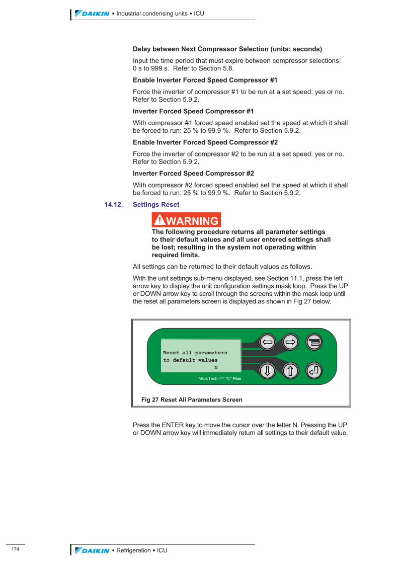
���
��������� ����������������������
������������������
Delay between Next Compressor Selection (units: seconds)
Input the time period that must expire between compressor selections: 0 s to 999 s. Refer to Section 5.8.
Enable Inverter Forced Speed Compressor #1
Force the inverter of compressor #1 to be run at a set speed: yes or no. Refer to Section 5.9.2.
Inverter Forced Speed Compressor #1
With compressor #1 forced speed enabled set the speed at which it shall be forced to run: 25 % to 99.9 %. Refer to Section 5.9.2.
Enable Inverter Forced Speed Compressor #2
Force the inverter of compressor #2 to be run at a set speed: yes or no. Refer to Section 5.9.2.
Inverter Forced Speed Compressor #2
With compressor #2 forced speed enabled set the speed at which it shall be forced to run: 25 % to 99.9 %. Refer to Section 5.9.2.
14.12. Settings Reset
�WARNING The following procedure returns all parameter settings to their default values and all user entered settings shall be lost; resulting in the system not operating within required limits.
All settings can be returned to their default values as follows.
With the unit settings sub-menu displayed, see Section 11.1, press the left arrow key to display the unit configuration settings mask loop. Press the UP or DOWN arrow key to scroll through the screens within the mask loop until the reset all parameters screen is displayed as shown in Fig 27 below.
Fig 27 Reset All Parameters Screen
Press the ENTER key to move the cursor over the letter N. Pressing the UP or DOWN arrow key will immediately return all settings to their default value.
Reset all parameters to default values N
MicroTech II™ "C" Plus
ICU.pdf 182 26/01/2011 11:11:56
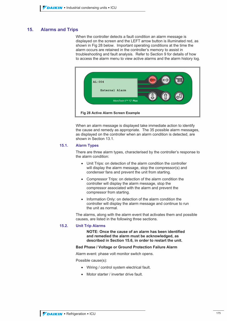
��������� ����������������������
������������������ ���
15. Alarms and Trips When the controller detects a fault condition an alarm message is displayed on the screen and the LEFT arrow button is illuminated red, as shown in Fig 28 below. Important operating conditions at the time the alarm occurs are retained in the controller’s memory to assist in troubleshooting and fault analysis. Refer to Section 9 for details of how to access the alarm menu to view active alarms and the alarm history log.
Fig 28 Active Alarm Screen Example
When an alarm message is displayed take immediate action to identify the cause and remedy as appropriate. The 35 possible alarm messages, as displayed on the controller when an alarm condition is detected, are shown in Section 13.1.
15.1. Alarm Types
There are three alarm types, characterised by the controller’s response to the alarm condition:
� Unit Trips: on detection of the alarm condition the controller will display the alarm message, stop the compressor(s) and condenser fans and prevent the unit from starting.
� Compressor Trips: on detection of the alarm condition the controller will display the alarm message, stop the compressor associated with the alarm and prevent the compressor from starting.
� Information Only: on detection of the alarm condition the controller will display the alarm message and continue to run the unit as normal.
The alarms, along with the alarm event that activates them and possible causes, are listed in the following three sections.
15.2. Unit Trip Alarms NOTE: Once the cause of an alarm has been identified and remedied the alarm must be acknowledged, as described in Section 15.6, in order to restart the unit.
Bad Phase / Voltage or Ground Protection Failure Alarm
Alarm event: phase volt monitor switch opens.
Possible cause(s):
� Wiring / control system electrical fault.
� Motor starter / inverter drive fault.
AL:004 External Alarm
MicroTech II™ "C" Plus
ICU.pdf 183 26/01/2011 11:11:56
���
��������� ����������������������
������������������
Remedial action:
� Inspect the wiring / control system for faults and repair or replace as necessary.
� Inspect motor starter / inverter drive for faults and repair or replace as necessary.
Fan Speed Control Fault Alarm
Possible cause(s):
� Wiring / control system electrical fault.
� Faulty motor starter / fan controller.
� Faulty condenser fan.
Remedial action:
� Inspect the wiring / control system for faults and repair or replace as necessary.
� Inspect motor starter / fan controller for faults and repair or replace as necessary.
� Inspect condenser fan for faults and repair or replace as necessary.
32k Clock Board Fault Alarm
Alarm event:
� 32k clock board malfunctions or is disconnected.
Possible cause(s):
� Malfunction of board.
� Board not connected.
Remedial action:
� Inspect board for faults and repair / replace as necessary.
� Ensure board correctly connected.
Low Oil Level in Separator Alarm
Alarm event: oil separator low level oil switch contacts remain open after the adjustable time delay has expired.
Possible cause(s):
� Wiring / control system electrical fault.
� Insufficient quantity of oil in separator.
� Foaming of oil in separator at start-up due to refrigerant condensing in the oil reservoir during the off-cycle.
� Opto-electronic liquid sensor fault.
Remedial action:
� Inspect the wiring / control system for faults and repair or replace as necessary.
� Check oil level and replenish as necessary.
� Check oil heater operation.
� Inspect sensor for faults and repair / replace as necessary.
ICU.pdf 184 26/01/2011 11:11:56
��������� ����������������������
������������������ ���
15.3. Compressor Trip Alarms NOTE: Once the cause of an alarm has been identified and remedied the alarm must be acknowledged, as described in Section 15.6, in order to restart the compressor.
Probe Failure Alarm
Alarm event: mA signal from probe / transducer goes out of permitted range for more than 10 seconds.
Possible cause(s):
� Probe out of calibration.
� Probe fault.
� Wiring / control system electrical fault.
� Probe disconnected.
Remedial action:
� Calibrate probe.
� Inspect probe for faults and repair or replace as necessary.
� Inspect the wiring / control system for faults and repair or replace as necessary.
� Ensure probe is correctly connected; refer to Table 4 for terminal connection details.
Compressor Overload Alarm
Alarm event: compressor overload switch contacts remains open for more than 5 seconds.
Possible cause(s):
� Wiring / control system electrical fault.
� Motor starter / inverter drive fault.
� Compressor fault.
Remedial action:
� Inspect the wiring / control system for faults and repair or replace as necessary.
� Inspect motor starter / inverter drive for faults and repair or replace as necessary.
� Inspect compressor for faults and repair or replace as necessary.
High Pressure Switch Alarm
Alarm event: compressor high pressure switch contacts open.
Possible cause(s):
� The pressure of the refrigerant vapour in the compressor discharge line has exceeded the high pressure cut-out switch setting.
� Wiring / control system electrical fault.
� High pressure cut out switch fault.
ICU.pdf 185 26/01/2011 11:11:56
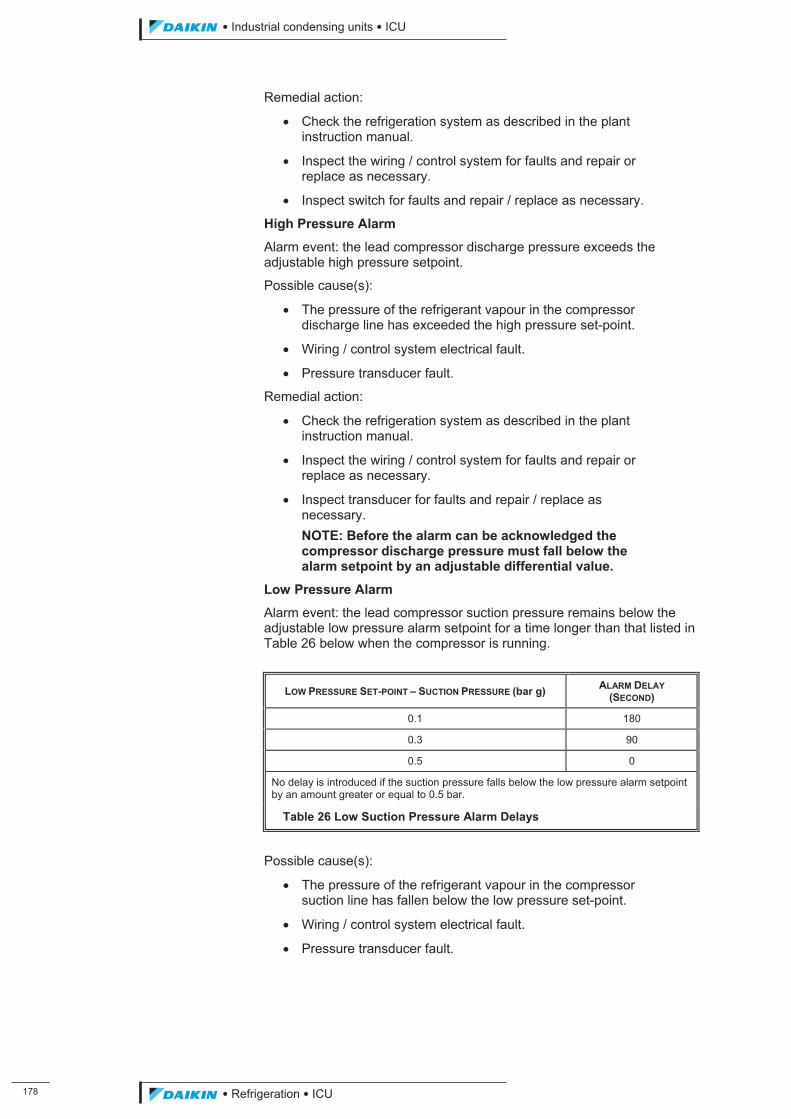
���
��������� ����������������������
������������������
Remedial action:
� Check the refrigeration system as described in the plant instruction manual.
� Inspect the wiring / control system for faults and repair or replace as necessary.
� Inspect switch for faults and repair / replace as necessary.
High Pressure Alarm
Alarm event: the lead compressor discharge pressure exceeds the adjustable high pressure setpoint.
Possible cause(s):
� The pressure of the refrigerant vapour in the compressor discharge line has exceeded the high pressure set-point.
� Wiring / control system electrical fault.
� Pressure transducer fault.
Remedial action:
� Check the refrigeration system as described in the plant instruction manual.
� Inspect the wiring / control system for faults and repair or replace as necessary.
� Inspect transducer for faults and repair / replace as necessary. NOTE: Before the alarm can be acknowledged the compressor discharge pressure must fall below the alarm setpoint by an adjustable differential value.
Low Pressure Alarm
Alarm event: the lead compressor suction pressure remains below the adjustable low pressure alarm setpoint for a time longer than that listed in Table 26 below when the compressor is running.
LOW PRESSURE SET-POINT – SUCTION PRESSURE (bar g) ALARM DELAY (SECOND)
0.1 180
0.3 90
0.5 0
No delay is introduced if the suction pressure falls below the low pressure alarm setpoint by an amount greater or equal to 0.5 bar.
Table 26 Low Suction Pressure Alarm Delays
Possible cause(s):
� The pressure of the refrigerant vapour in the compressor suction line has fallen below the low pressure set-point.
� Wiring / control system electrical fault.
� Pressure transducer fault.
ICU.pdf 186 26/01/2011 11:11:56
��������� ����������������������
������������������ ���
Remedial action:
� Check the refrigeration system as described in the plant instruction manual.
� Inspect the wiring / control system for faults and repair or replace as necessary.
� Inspect transducer for faults and repair / replace as necessary. NOTE: Before the alarm can be acknowledged the compressor suction pressure must rise above the alarm setpoint by an adjustable differential value.
High Discharge Temperature
Alarm event: the compressor discharge temperature exceeds the adjustable high temperature setpoint.
Possible cause(s):
� The temperature of the refrigerant vapour in the compressor discharge line has exceeded the high temperature set-point.
� Wiring / control system electrical fault.
� Temperature sensor fault.
Remedial action:
� Check the refrigeration system as described in the plant instruction manual.
� Inspect the wiring / control system for faults and repair or replace as necessary.
� Inspect temperature sensor for faults and repair / replace as necessary.
Failed Transition or Solid State Alarm
Alarm event: the transition / solid state (compressor run) alarm switch remains open for more than 10 seconds after compressor start-up.
Possible cause(s):
� Wiring / control system electrical fault.
� Motor starter / inverter drive fault.
� Compressor fault.
Remedial action:
� Inspect the wiring / control system for faults and repair or replace as necessary.
� Inspect motor starter / inverter drive for faults and repair or replace as necessary.
� Inspect compressor for faults and repair or replace as necessary.
Low Oil Pressure
Alarm event: the oil pressure remains below the adjustable oil level low pressure setpoint value, as shown in Table 27 on the following page, after the adjustable start-up or running delay has expired.
ICU.pdf 187 26/01/2011 11:11:56
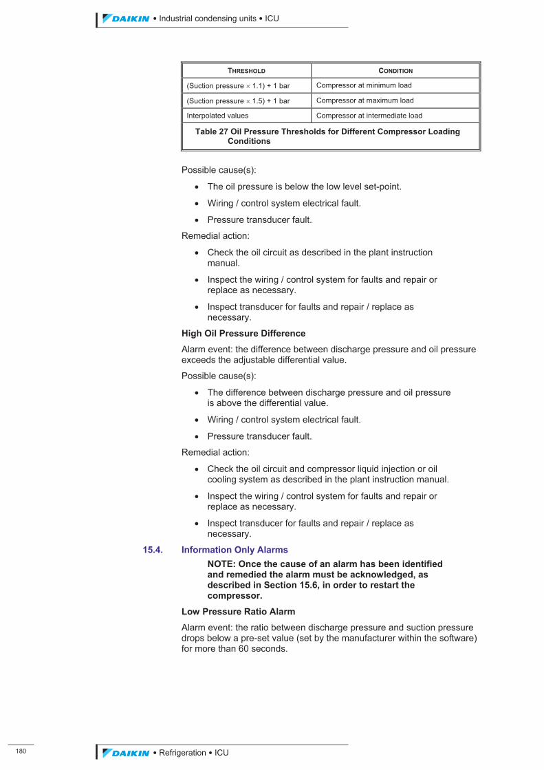
��
��������� ����������������������
������������������
THRESHOLD CONDITION
(Suction pressure � 1.1) + 1 bar Compressor at minimum load
(Suction pressure � 1.5) + 1 bar Compressor at maximum load
Interpolated values Compressor at intermediate load
Table 27 Oil Pressure Thresholds for Different Compressor Loading Conditions
Possible cause(s):
� The oil pressure is below the low level set-point.
� Wiring / control system electrical fault.
� Pressure transducer fault.
Remedial action:
� Check the oil circuit as described in the plant instruction manual.
� Inspect the wiring / control system for faults and repair or replace as necessary.
� Inspect transducer for faults and repair / replace as necessary.
High Oil Pressure Difference
Alarm event: the difference between discharge pressure and oil pressure exceeds the adjustable differential value.
Possible cause(s):
� The difference between discharge pressure and oil pressure is above the differential value.
� Wiring / control system electrical fault.
� Pressure transducer fault.
Remedial action:
� Check the oil circuit and compressor liquid injection or oil cooling system as described in the plant instruction manual.
� Inspect the wiring / control system for faults and repair or replace as necessary.
� Inspect transducer for faults and repair / replace as necessary.
15.4. Information Only Alarms NOTE: Once the cause of an alarm has been identified and remedied the alarm must be acknowledged, as described in Section 15.6, in order to restart the compressor.
Low Pressure Ratio Alarm
Alarm event: the ratio between discharge pressure and suction pressure drops below a pre-set value (set by the manufacturer within the software) for more than 60 seconds.
ICU.pdf 188 26/01/2011 11:11:56
��������� ����������������������
������������������ ���
Possible cause(s):
� The ratio between discharge pressure and suction pressure is too low.
� Wiring / control system electrical fault.
� Pressure transducer fault.
Remedial action:
� Check the refrigeration system as described in the plant instruction manual.
� Inspect the wiring / control system for faults and repair or replace as necessary.
� Inspect transducer for faults and repair / replace as necessary.
Compressor Maintenance
Alarm event: the compressor hours run meter exceeds the adjustable setpoint for required maintenance.
Possible cause(s):
� Compressor hours run meter setpoint exceeded.
Remedial action:
� Reset the hours run meter as detailed in Section 12.4.
15.5. External Alarm
When enabled the external alarm message is displayed when the external alarm switch contacts open. The controller can also be configured to stop the unit on external alarm.
15.6. Alarm Acknowledgement
Pressing the LEFT arrow key when a fault condition alarm is displayed acknowledges the alarm. If the fault condition has been rectified the controller is reset, the red light on the LEFT arrow button extinguished and a ‘No Alarm Detected’ message displayed on the screen. If the fault condition remains then the alarm is reactivated.
If more than one fault condition occurs then the first fault condition is displayed. Use the view active alarm function, as detailed in Section 9.1, to view all active alarms.
NOTE: Pressing the LEFT arrow key acknowledges all active alarms.
15.7. Alarm Log Reset
Details of the last 10 alarms are stored within the alarm log; refer to Section 9.2. When this limit is reached each new entry replaces the oldest entry in the log. It is not possible to delete individual entries however the alarm log can be completely cleared as follows.
At the main menu press the DOWN arrow key to display the maintenance sub-menu as shown in Fig 29 on the following page.
ICU.pdf 189 26/01/2011 11:11:57
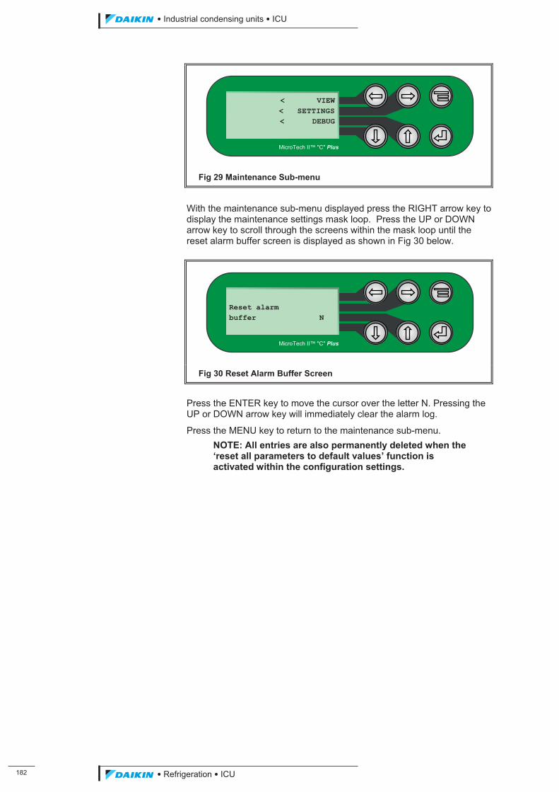
���
��������� ����������������������
������������������
Fig 29 Maintenance Sub-menu
With the maintenance sub-menu displayed press the RIGHT arrow key to display the maintenance settings mask loop. Press the UP or DOWN arrow key to scroll through the screens within the mask loop until the reset alarm buffer screen is displayed as shown in Fig 30 below.
Fig 30 Reset Alarm Buffer Screen
Press the ENTER key to move the cursor over the letter N. Pressing the UP or DOWN arrow key will immediately clear the alarm log.
Press the MENU key to return to the maintenance sub-menu. NOTE: All entries are also permanently deleted when the ‘reset all parameters to default values’ function is activated within the configuration settings.
Reset alarm buffer N
MicroTech II™ "C" Plus
< VIEW< SETTINGS< DEBUG
MicroTech II™ "C" Plus
ICU.pdf 190 26/01/2011 11:11:57
��������� ����������������������
������������������ ���
16. Maintenance and Spares 16.1. Maintenance
Under normal operating conditions with the controller operating correctly, minimum servicing is required or recommended. The following general checks are recommended once a year.
� Check measured point values against pressure gauges, thermometers and current meter readings.
� Check for damage to external wiring.
� Check screw terminals, fuse-holders etc., for loose connections.
A full transducer calibration check is recommended every 5 years; refer to the instruction manual of the transducer.
The lithium battery used to back up the controller’s settings should be checked after 5 years, then every year until the battery needs replacing; refer to Section 16.2.
16.1.1. Maintenance Check List
Table 28 illustrates the maintenance items as a ‘Check List’.
REF. MAINTENANCE ITEM FREQUENCY
YEARLY 5 YEARLY
-
Check measured point values against pressure gauges, thermometers and current meter readings.
Check damage to external wiring.
Check screw terminals, fuse-holders etc., for loose connections.
X -
16.2 Check and if necessary renew the back-up battery. After the first check after 5 years, check the battery voltage every year.
- X
Table 28 Maintenance Check List
16.2. Checking and Replacement of Lithium Back-up Battery
The lithium back-up battery is mounted on the main control board, inside the enclosure.
The battery provides the power required to maintain the controller’s settings when the power is switched off or in the event of a mains power supply failure. A healthy, fully charged battery should retain memory in the processor for at least 6 months.
After 5 years operation the battery will be nearing the end of its useful life and may begin to fade. Check the battery output voltage which should be between 2.7 V and 3.0 V when measured between the controllers 0 V terminal and the face of the battery. If the voltage is within limit, check the battery voltage every year until it needs replacing.
Fit a new battery as follows:
(a) Check to make sure all configuration settings have been correctly recorded in the table Section 19 in order that they may be re-entered after the battery has been replaced.
(b) Observe and record the hours run and number of starts for each compressor; refer to Section 12.4 and 12.5.
ICU.pdf 191 26/01/2011 11:11:57
���
��������� ����������������������
������������������
(c) Stop the plant and turn off the power supply to the controller.
(d) Remove terminal connections J19 to J23; refer to Section 6.
� CAUTION Never remove the cover of the controller’s enclosure with the power supply turned on.
(e) Use a flat bladed screwdriver to depress the retaining clips, two located at each end of the controller, and carefully lift off the enclosure cover.
NOTE: electronic cards are easily damaged by static electricity. The anti-static precautions detailed in Section 2.1 must be taken.
(f) The battery is located near the centre of the main board and is secured under a spring-loaded clip. Disengage the clip to remove the old battery and fit the new one.
� WARNING Ensure the new battery is fitted the correct way round, positive (+) pole uppermost, or the control board may be damaged.
If possible, return the old battery to the manufacturer for recycling; otherwise, dispose of safely. DO NOT attempt to open the battery or incinerate it.
(g) Re-fit the enclosure cover.
(h) Re-fit terminal connections J19 to J23; refer to Section 6.
(i) Turn on the power supply to the controller.
(j) Re-enter the configuration settings as recorded in step (a) above; refer to Section 8.5.
(k) Reset the hours run and number of start meters to the values recorded in step (b) above; refer to Section 12.4 and 12.5.
16.3. Fuse Replacement
The fuse is mounted within a fuse-holder located on the bottom left-hand corner of the controller; refer to Section 6.
The fuse protects the controller from being damaged by excessive current by failing if the current exceeds the current rating of the fuse. The fuse will only need to be replaced if it fails and must only be replaced with a fuse of the type and rating originally fitted. If repeated fuse failures occur then further checks must be made to indentify and rectify the cause of the repeated overcurrent condition.
Fit a new fuse as follows:
(a) Turn off the power supply to the controller.
� CAUTION Never remove the cover of the fuse-holder with the power supply turned on.
(b) Remove the cover of the fuse-holder. As the fuse is held within the fuse-holder cover this also removes the fuse.
ICU.pdf 192 26/01/2011 11:11:57
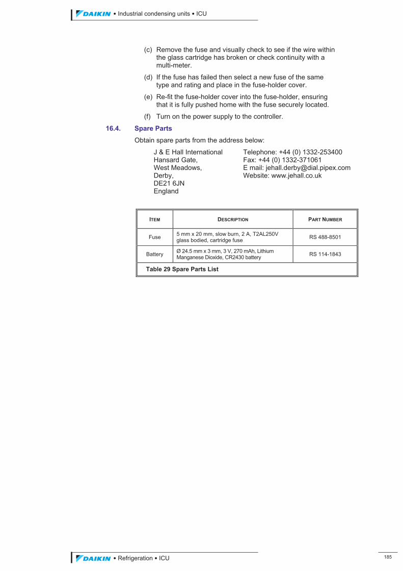
��������� ����������������������
������������������ ���
(c) Remove the fuse and visually check to see if the wire within the glass cartridge has broken or check continuity with a multi-meter.
(d) If the fuse has failed then select a new fuse of the same type and rating and place in the fuse-holder cover.
(e) Re-fit the fuse-holder cover into the fuse-holder, ensuring that it is fully pushed home with the fuse securely located.
(f) Turn on the power supply to the controller.
16.4. Spare Parts
Obtain spare parts from the address below:
J & E Hall International Telephone: +44 (0) 1332-253400 Hansard Gate, Fax: +44 (0) 1332-371061 West Meadows, E mail: [email protected] Derby, Website: www.jehall.co.uk DE21 6JN England
ITEM DESCRIPTION PART NUMBER
Fuse 5 mm x 20 mm, slow burn, 2 A, T2AL250V glass bodied, cartridge fuse RS 488-8501
Battery Ø 24.5 mm x 3 mm, 3 V, 270 mAh, Lithium Manganese Dioxide, CR2430 battery RS 114-1843
Table 29 Spare Parts List
ICU.pdf 193 26/01/2011 11:11:57
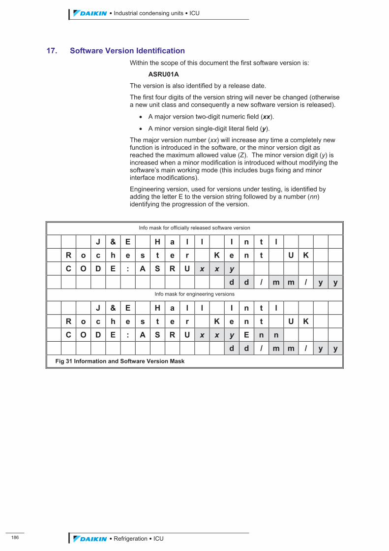
���
��������� ����������������������
������������������
17. Software Version Identification Within the scope of this document the first software version is:
ASRU01A
The version is also identified by a release date.
The first four digits of the version string will never be changed (otherwise a new unit class and consequently a new software version is released).
� A major version two-digit numeric field (xx).
� A minor version single-digit literal field (y).
The major version number (xx) will increase any time a completely new function is introduced in the software, or the minor version digit as reached the maximum allowed value (Z). The minor version digit (y) is increased when a minor modification is introduced without modifying the software’s main working mode (this includes bugs fixing and minor interface modifications).
Engineering version, used for versions under testing, is identified by adding the letter E to the version string followed by a number (nn) identifying the progression of the version.
Info mask for officially released software version
J & E H a l l I n t l R o c h e s t e r K e n t U K C O D E : A S R U x x y d d / m m / y y
Info mask for engineering versions
J & E H a l l I n t l R o c h e s t e r K e n t U K C O D E : A S R U x x y E n n d d / m m / y y Fig 31 Information and Software Version Mask
ICU.pdf 194 26/01/2011 11:11:57
��������� ����������������������
������������������ ���
18. Communications Remote communication is via the RS485 serial port on the MicroTech II C+ control board.
18.1. Protocols Supported
The following communication protocols are supported:
� Local
Communication with a supervisory system using Carel Slave Local protocol (for example PlantVisor, PlantWatch, WebGate and Gateway). Suitable for communication with Trend®, LonWorks®, pCO WEB and BACnet® optional cards.
� Remote
Used to manage an analogue modem. The communication speed is automatically set to 19200 baud.
� Modbus slave
Used to communicate with Modbus compatible supervisory systems. The communication addresses for communicating with Modbus supervisory systems are detailed in the tables shown in Section 18.4 through to Section 18.6.
� Lonworks and Backnet
Same as Local protocol. In case of Lonworks communication, the communication speed is automatically set to 4800 baud.
18.2. Communication Speed
With the communication device connected to the RS485 interface the communication speed (units: baud) can be set to one of the following:
� 1200.
� 2400.
� 4800.
� 9600.
� 19200.
18.3. Modem
With an analogue modem connected an identity number and password can be selected within the user setpoint settings.
ICU.pdf 195 26/01/2011 11:11:57
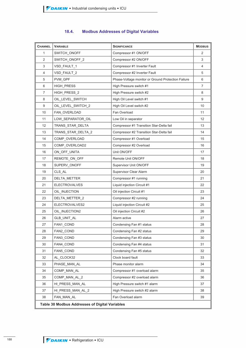
���
��������� ����������������������
������������������
18.4. Modbus Addresses of Digital Variables
CHANNEL VARIABLE SIGNIFICANCE MODBUS
1 SWITCH_ONOFF Compressor #1 ON/OFF 2
2 SWITCH_ONOFF_2 Compressor #2 ON/OFF 3
3 VSD_FAULT_1 Compressor #1 Inverter Fault 4
4 VSD_FAULT_2 Compressor #2 Inverter Fault 5
5 PVM_GPF Phase-Voltage monitor or Ground Protection Failure 6
6 HIGH_PRESS High Pressure switch #1 7
7 HIGH_PRESS_2 High Pressure switch #2 8
8 OIL_LEVEL_SWITCH High Oil Level switch #1 9
9 OIL_LEVEL_SWITCH_2 High Oil Level switch #2 10
10 FAN_OVERLOAD Fan Overload 11
11 LOW_SEPARATOR_OIL Low Oil in separator 12
12 TRANS_STAR_DELTA Compressor #1 Transition Star-Delta fail 13
13 TRANS_STAR_DELTA_2 Compressor #2 Transition Star-Delta fail 14
14 COMP_OVERLOAD Compressor #1 Overload 15
15 COMP_OVERLOAD2 Compressor #2 Overload 16
16 ON_OFF_UNITA Unit ON/OFF 17
17 REMOTE_ON_OFF Remote Unit ON/OFF 18
18 SUPERV_ONOFF Supervisor Unit ON/OFF 19
19 CLS_AL Supervisor Clear Alarm 20
20 DELTA_METTER Compressor #1 running 21
21 ELECTROVALVES Liquid injection Circuit #1 22
22 OIL_INJECTION Oil injection Circuit #1 23
23 DELTA_METTER_2 Compressor #2 running 24
24 ELECTROVALVES2 Liquid injection Circuit #2 25
25 OIL_INJECTION2 Oil injection Circuit #2 26
26 GLB_UNIT_AL Alarm active 27
27 FAN1_COND Condensing Fan #1 status 28
28 FAN2_COND Condensing Fan #2 status 29
29 FAN3_COND Condensing Fan #3 status 30
30 FAN4_COND Condensing Fan #4 status 31
31 FAN5_COND Condensing Fan #5 status 32
32 AL_CLOCK32 Clock board fault 33
33 PHASE_MAN_AL Phase monitor alarm 34
34 COMP_MAN_AL Compressor #1 overload alarm 35
35 COMP_MAN_AL_2 Compressor #2 overload alarm 36
36 HI_PRESS_MAN_AL High Pressure switch #1 alarm 37
37 HI_PRESS_MAN_AL_2 High Pressure switch #2 alarm 38
38 FAN_MAN_AL Fan Overload alarm 39
Table 30 Modbus Addresses of Digital Variables
ICU.pdf 196 26/01/2011 11:11:57
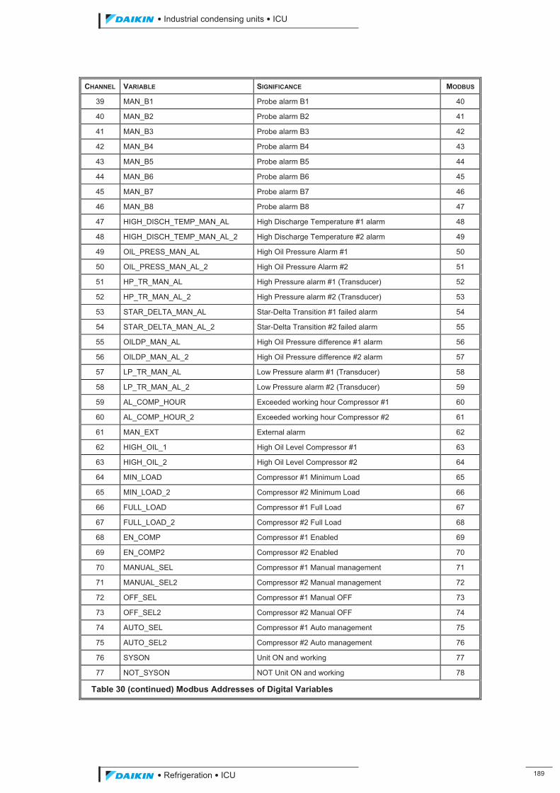
��������� ����������������������
������������������ ���
CHANNEL VARIABLE SIGNIFICANCE MODBUS
39 MAN_B1 Probe alarm B1 40
40 MAN_B2 Probe alarm B2 41
41 MAN_B3 Probe alarm B3 42
42 MAN_B4 Probe alarm B4 43
43 MAN_B5 Probe alarm B5 44
44 MAN_B6 Probe alarm B6 45
45 MAN_B7 Probe alarm B7 46
46 MAN_B8 Probe alarm B8 47
47 HIGH_DISCH_TEMP_MAN_AL High Discharge Temperature #1 alarm 48
48 HIGH_DISCH_TEMP_MAN_AL_2 High Discharge Temperature #2 alarm 49
49 OIL_PRESS_MAN_AL High Oil Pressure Alarm #1 50
50 OIL_PRESS_MAN_AL_2 High Oil Pressure Alarm #2 51
51 HP_TR_MAN_AL High Pressure alarm #1 (Transducer) 52
52 HP_TR_MAN_AL_2 High Pressure alarm #2 (Transducer) 53
53 STAR_DELTA_MAN_AL Star-Delta Transition #1 failed alarm 54
54 STAR_DELTA_MAN_AL_2 Star-Delta Transition #2 failed alarm 55
55 OILDP_MAN_AL High Oil Pressure difference #1 alarm 56
56 OILDP_MAN_AL_2 High Oil Pressure difference #2 alarm 57
57 LP_TR_MAN_AL Low Pressure alarm #1 (Transducer) 58
58 LP_TR_MAN_AL_2 Low Pressure alarm #2 (Transducer) 59
59 AL_COMP_HOUR Exceeded working hour Compressor #1 60
60 AL_COMP_HOUR_2 Exceeded working hour Compressor #2 61
61 MAN_EXT External alarm 62
62 HIGH_OIL_1 High Oil Level Compressor #1 63
63 HIGH_OIL_2 High Oil Level Compressor #2 64
64 MIN_LOAD Compressor #1 Minimum Load 65
65 MIN_LOAD_2 Compressor #2 Minimum Load 66
66 FULL_LOAD Compressor #1 Full Load 67
67 FULL_LOAD_2 Compressor #2 Full Load 68
68 EN_COMP Compressor #1 Enabled 69
69 EN_COMP2 Compressor #2 Enabled 70
70 MANUAL_SEL Compressor #1 Manual management 71
71 MANUAL_SEL2 Compressor #2 Manual management 72
72 OFF_SEL Compressor #1 Manual OFF 73
73 OFF_SEL2 Compressor #2 Manual OFF 74
74 AUTO_SEL Compressor #1 Auto management 75
75 AUTO_SEL2 Compressor #2 Auto management 76
76 SYSON Unit ON and working 77
77 NOT_SYSON NOT Unit ON and working 78
Table 30 (continued) Modbus Addresses of Digital Variables
ICU.pdf 197 26/01/2011 11:11:57
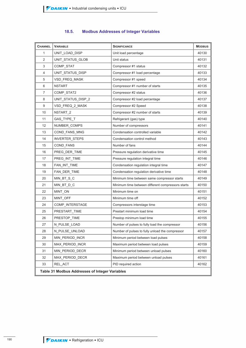
��
��������� ����������������������
������������������
18.5. Modbus Addresses of Integer Variables
CHANNEL VARIABLE SIGNIFICANCE MODBUS
1 UNIT_LOAD_DISP Unit load percentage 40130
2 UNIT_STATUS_GLOB Unit status 40131
3 COMP_STAT Compressor #1 status 40132
4 UNIT_STATUS_DISP Compressor #1 load percentage 40133
5 VSD_FREQ_MASK Compressor #1 speed 40134
6 NSTART Compressor #1 number of starts 40135
7 COMP_STAT2 Compressor #2 status 40136
8 UNIT_STATUS_DISP_2 Compressor #2 load percentage 40137
9 VSD_FREQ_2_MASK Compressor #2 Speed 40138
10 NSTART_2 Compressor #2 number of starts 40139
11 GAS_TYPE_T Refrigerant (gas) type 40140
12 NUMBER_COMPS Number of compressors 40141
13 COND_FANS_MNG Condensation controlled variable 40142
14 INVERTER_STEPS Condensation control method 40143
15 COND_FANS Number of fans 40144
16 PREG_DER_TIME Pressure regulation derivative time 40145
17 PREG_INT_TIME Pressure regulation integral time 40146
18 FAN_INT_TIME Condensation regulation integral time 40147
19 FAN_DER_TIME Condensation regulation derivative time 40148
20 MIN_BT_S_C Minimum time between same compressor starts 40149
21 MIN_BT_D_C Minimum time between different compressors starts 40150
22 MINT_ON Minimum time on 40151
23 MINT_OFF Minimum time off 40152
24 COMP_INTERSTAGE Compressors interstage time 40153
25 PRESTART_TIME Prestart minimum load time 40154
26 PRESTOP_TIME Prestop minimum load time 40155
27 N_PULSE_LOAD Number of pulses to fully load the compressor 40156
28 N_PULSE_UNLOAD Number of pulses to fully unload the compressor 40157
29 MIN_PERIOD_INCR Minimum period between load pulses 40158
30 MAX_PERIOD_INCR Maximum period between load pulses 40159
31 MIN_PERIOD_DECR Minimum period between unload pulses 40160
32 MAX_PERIOD_DECR Maximum period between unload pulses 40161
33 REL_ACT PID required action 40162
Table 31 Modbus Addresses of Integer Variables
ICU.pdf 198 26/01/2011 11:11:57
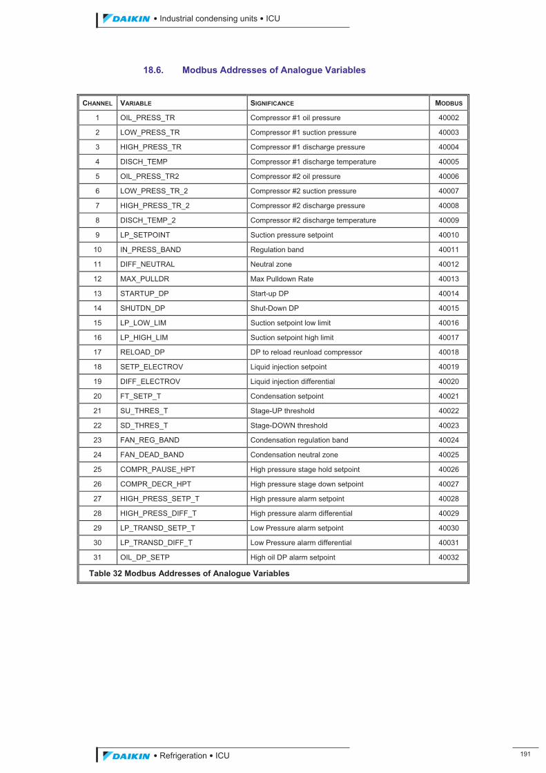
��������� ����������������������
������������������ ���
18.6. Modbus Addresses of Analogue Variables
CHANNEL VARIABLE SIGNIFICANCE MODBUS
1 OIL_PRESS_TR Compressor #1 oil pressure 40002
2 LOW_PRESS_TR Compressor #1 suction pressure 40003
3 HIGH_PRESS_TR Compressor #1 discharge pressure 40004
4 DISCH_TEMP Compressor #1 discharge temperature 40005
5 OIL_PRESS_TR2 Compressor #2 oil pressure 40006
6 LOW_PRESS_TR_2 Compressor #2 suction pressure 40007
7 HIGH_PRESS_TR_2 Compressor #2 discharge pressure 40008
8 DISCH_TEMP_2 Compressor #2 discharge temperature 40009
9 LP_SETPOINT Suction pressure setpoint 40010
10 IN_PRESS_BAND Regulation band 40011
11 DIFF_NEUTRAL Neutral zone 40012
12 MAX_PULLDR Max Pulldown Rate 40013
13 STARTUP_DP Start-up DP 40014
14 SHUTDN_DP Shut-Down DP 40015
15 LP_LOW_LIM Suction setpoint low limit 40016
16 LP_HIGH_LIM Suction setpoint high limit 40017
17 RELOAD_DP DP to reload reunload compressor 40018
18 SETP_ELECTROV Liquid injection setpoint 40019
19 DIFF_ELECTROV Liquid injection differential 40020
20 FT_SETP_T Condensation setpoint 40021
21 SU_THRES_T Stage-UP threshold 40022
22 SD_THRES_T Stage-DOWN threshold 40023
23 FAN_REG_BAND Condensation regulation band 40024
24 FAN_DEAD_BAND Condensation neutral zone 40025
25 COMPR_PAUSE_HPT High pressure stage hold setpoint 40026
26 COMPR_DECR_HPT High pressure stage down setpoint 40027
27 HIGH_PRESS_SETP_T High pressure alarm setpoint 40028
28 HIGH_PRESS_DIFF_T High pressure alarm differential 40029
29 LP_TRANSD_SETP_T Low Pressure alarm setpoint 40030
30 LP_TRANSD_DIFF_T Low Pressure alarm differential 40031
31 OIL_DP_SETP High oil DP alarm setpoint 40032
Table 32 Modbus Addresses of Analogue Variables
ICU.pdf 199 26/01/2011 11:11:57
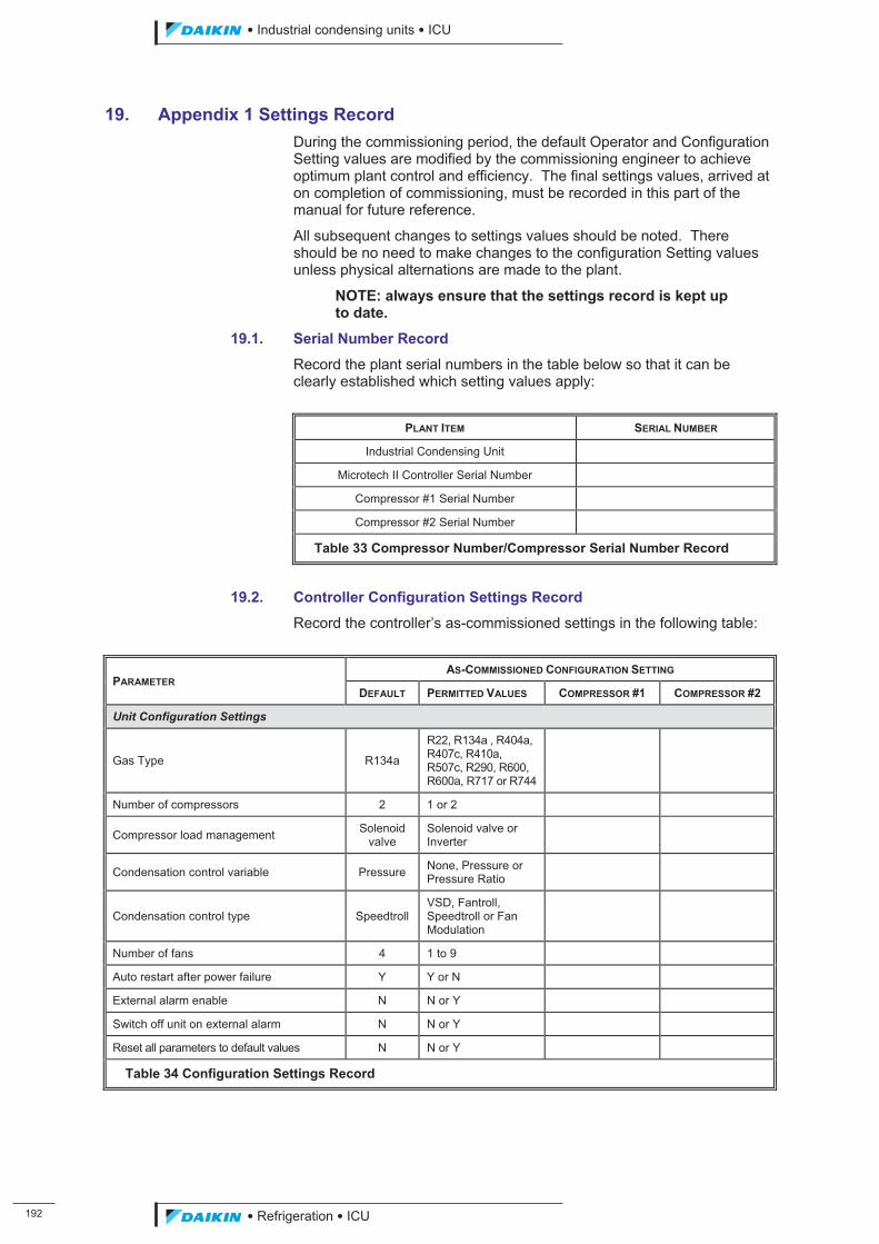
���
��������� ����������������������
������������������
19. Appendix 1 Settings Record During the commissioning period, the default Operator and Configuration Setting values are modified by the commissioning engineer to achieve optimum plant control and efficiency. The final settings values, arrived at on completion of commissioning, must be recorded in this part of the manual for future reference.
All subsequent changes to settings values should be noted. There should be no need to make changes to the configuration Setting values unless physical alternations are made to the plant.
NOTE: always ensure that the settings record is kept up to date.
19.1. Serial Number Record
Record the plant serial numbers in the table below so that it can be clearly established which setting values apply:
PLANT ITEM SERIAL NUMBER
Industrial Condensing Unit
Microtech II Controller Serial Number
Compressor #1 Serial Number
Compressor #2 Serial Number
Table 33 Compressor Number/Compressor Serial Number Record
19.2. Controller Configuration Settings Record
Record the controller’s as-commissioned settings in the following table:
PARAMETER AS-COMMISSIONED CONFIGURATION SETTING
DEFAULT PERMITTED VALUES COMPRESSOR #1 COMPRESSOR #2
Unit Configuration Settings
Gas Type R134a
R22, R134a , R404a, R407c, R410a, R507c, R290, R600, R600a, R717 or R744
Number of compressors 2 1 or 2
Compressor load management Solenoid valve
Solenoid valve or Inverter
Condensation control variable Pressure None, Pressure or Pressure Ratio
Condensation control type Speedtroll VSD, Fantroll, Speedtroll or Fan Modulation
Number of fans 4 1 to 9
Auto restart after power failure Y Y or N
External alarm enable N N or Y
Switch off unit on external alarm N N or Y
Reset all parameters to default values N N or Y
Table 34 Configuration Settings Record
ICU.pdf 200 26/01/2011 11:11:57
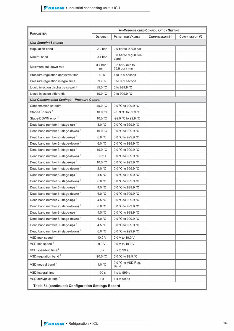
��������� ����������������������
������������������ ���
PARAMETER AS-COMMISSIONED CONFIGURATION SETTING
DEFAULT PERMITTED VALUES COMPRESSOR #1 COMPRESSOR #2
Unit Setpoint Settings
Regulation band 2.0 bar 0.0 bar to 999.9 bar
Neutral band 0.1 bar 0.0 bar to regulation band
Maximum pull-down rate 0.7 bar / min
0.2 bar / min to 99.9 bar / min
Pressure regulation derivative time 60 s 1 to 999 second
Pressure regulation integral time 900 s 0 to 999 second
Liquid injection discharge setpoint 85.0 °C 0 to 999.9 °C
Liquid injection differential 10.0 °C 0 to 999.9 °C
Unit Condensation Settings – Pressure Control
Condensation setpoint 40.0 °C 0.0 °C to 999.9 °C
Stage-UP error 1 10.0 °C -99.9 °C to 99.9 °C
Stage-DOWN error 1 10.0 °C -99.9 °C to 99.9 °C
Dead band number 1 (stage-up) 1 3.0 °C 0.0 °C to 999.9 °C
Dead band number 1 (stage-down) 1 10.0 °C 0.0 °C to 999.9 °C
Dead band number 2 (stage-up) 1 6.0 °C 0.0 °C to 999.9 °C
Dead band number 2 (stage-down) 1 6.0 °C 0.0 °C to 999.9 °C
Dead band number 3 (stage-up) 1 10.0 °C 0.0 °C to 999.9 °C
Dead band number 3 (stage-down) 1 3.0°C 0.0 °C to 999.9 °C
Dead band number 4 (stage-up) 1 10.0 °C 0.0 °C to 999.9 °C
Dead band number 4 (stage-down) 1 2.0 °C 0.0 °C to 999.9 °C
Dead band number 5 (stage-up) 1 4.5 °C 0.0 °C to 999.9 °C
Dead band number 5 (stage-down) 1 6.0 °C 0.0 °C to 999.9 °C
Dead band number 6 (stage-up) 1 4.5 °C 0.0 °C to 999.9 °C
Dead band number 6 (stage-down) 1 6.0 °C 0.0 °C to 999.9 °C
Dead band number 7 (stage-up) 1 4.5 °C 0.0 °C to 999.9 °C
Dead band number 7 (stage-down) 1 6.0 °C 0.0 °C to 999.9 °C
Dead band number 8 (stage-up) 1 4.5 °C 0.0 °C to 999.9 °C
Dead band number 8 (stage-down) 1 6.0 °C 0.0 °C to 999.9 °C
Dead band number 9 (stage-up) 1 4.5 °C 0.0 °C to 999.9 °C
Dead band number 9 (stage-down) 1 6.0 °C 0.0 °C to 999.9 °C
VSD max speed 2 10.0 V 0.0 V to 10.0 V
VSD min speed 2 0.0 V 0.0 V to 10.0 V
VSD speed-up time 2 0 s 0 s to 99 s
VSD regulation band 2 20.0 °C 0.0 °C to 99.9 °C
VSD neutral band 2 1.0 °C 0.0 °C to VSD Reg. Band
VSD integral time 2 150 s 1 s to 999 s
VSD derivative time 2 1 s 1 s to 999 s
Table 34 (continued) Configuration Settings Record
ICU.pdf 201 26/01/2011 11:11:58
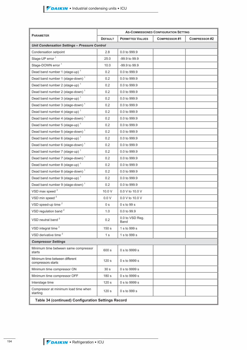
���
��������� ����������������������
������������������
PARAMETER AS-COMMISSIONED CONFIGURATION SETTING
DEFAULT PERMITTED VALUES COMPRESSOR #1 COMPRESSOR #2
Unit Condensation Settings – Pressure Control
Condensation setpoint 2.8 0.0 to 999.9
Stage-UP error 1 25.0 -99.9 to 99.9
Stage-DOWN error 1 10.0 -99.9 to 99.9
Dead band number 1 (stage-up) 1 0.2 0.0 to 999.9
Dead band number 1 (stage-down) 1 0.2 0.0 to 999.9
Dead band number 2 (stage-up) 1 0.2 0.0 to 999.9
Dead band number 2 (stage-down) 1 0.2 0.0 to 999.9
Dead band number 3 (stage-up) 1 0.2 0.0 to 999.9
Dead band number 3 (stage-down) 1 0.2 0.0 to 999.9
Dead band number 4 (stage-up) 1 0.2 0.0 to 999.9
Dead band number 4 (stage-down) 1 0.2 0.0 to 999.9
Dead band number 5 (stage-up) 1 0.2 0.0 to 999.9
Dead band number 5 (stage-down) 1 0.2 0.0 to 999.9
Dead band number 6 (stage-up) 1 0.2 0.0 to 999.9
Dead band number 6 (stage-down) 1 0.2 0.0 to 999.9
Dead band number 7 (stage-up) 1 0.2 0.0 to 999.9
Dead band number 7 (stage-down) 1 0.2 0.0 to 999.9
Dead band number 8 (stage-up) 1 0.2 0.0 to 999.9
Dead band number 8 (stage-down) 1 0.2 0.0 to 999.9
Dead band number 9 (stage-up) 1 0.2 0.0 to 999.9
Dead band number 9 (stage-down) 1 0.2 0.0 to 999.9
VSD max speed 2 10.0 V 0.0 V to 10.0 V
VSD min speed 2 0.0 V 0.0 V to 10.0 V
VSD speed-up time 2 0 s 0 s to 99 s
VSD regulation band 2 1.0 0.0 to 99.9
VSD neutral band 2 0.2 0.0 to VSD Reg. Band
VSD integral time 2 150 s 1 s to 999 s
VSD derivative time 2 1 s 1 s to 999 s
Compressor Settings
Minimum time between same compressor starts 600 s 0 s to 9999 s
Minimum time between different compressors starts 120 s 0 s to 9999 s
Minimum time compressor ON 30 s 0 s to 9999 s
Minimum time compressor OFF 180 s 0 s to 9999 s
Interstage time 120 s 0 s to 9999 s
Compressor at minimum load time when starting 120 s 0 s to 999 s
Table 34 (continued) Configuration Settings Record
ICU.pdf 202 26/01/2011 11:11:58
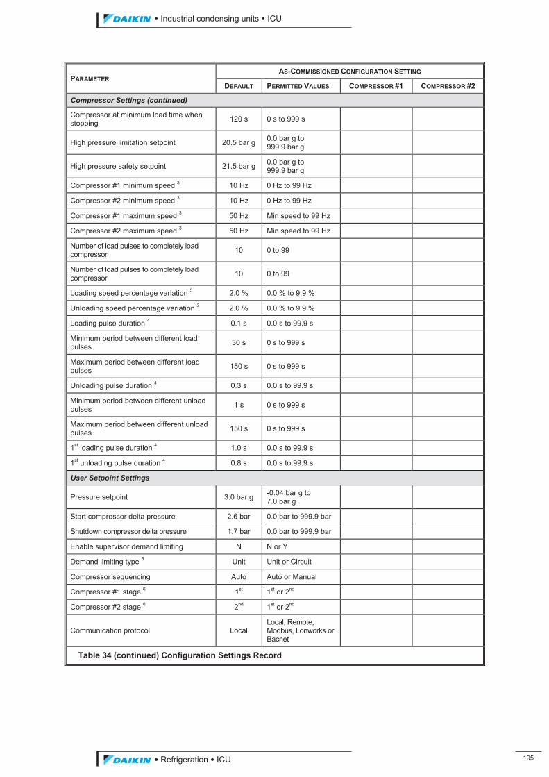
��������� ����������������������
������������������ ���
PARAMETER AS-COMMISSIONED CONFIGURATION SETTING
DEFAULT PERMITTED VALUES COMPRESSOR #1 COMPRESSOR #2
Compressor Settings (continued)
Compressor at minimum load time when stopping 120 s 0 s to 999 s
High pressure limitation setpoint 20.5 bar g 0.0 bar g to 999.9 bar g
High pressure safety setpoint 21.5 bar g 0.0 bar g to 999.9 bar g
Compressor #1 minimum speed 3 10 Hz 0 Hz to 99 Hz
Compressor #2 minimum speed 3 10 Hz 0 Hz to 99 Hz
Compressor #1 maximum speed 3 50 Hz Min speed to 99 Hz
Compressor #2 maximum speed 3 50 Hz Min speed to 99 Hz
Number of load pulses to completely load compressor 10 0 to 99
Number of load pulses to completely load compressor 10 0 to 99
Loading speed percentage variation 3 2.0 % 0.0 % to 9.9 %
Unloading speed percentage variation 3 2.0 % 0.0 % to 9.9 %
Loading pulse duration 4 0.1 s 0.0 s to 99.9 s
Minimum period between different load pulses 30 s 0 s to 999 s
Maximum period between different load pulses 150 s 0 s to 999 s
Unloading pulse duration 4 0.3 s 0.0 s to 99.9 s
Minimum period between different unload pulses 1 s 0 s to 999 s
Maximum period between different unload pulses 150 s 0 s to 999 s
1st loading pulse duration 4 1.0 s 0.0 s to 99.9 s
1st unloading pulse duration 4 0.8 s 0.0 s to 99.9 s
User Setpoint Settings
Pressure setpoint 3.0 bar g -0.04 bar g to 7.0 bar g
Start compressor delta pressure 2.6 bar 0.0 bar to 999.9 bar
Shutdown compressor delta pressure 1.7 bar 0.0 bar to 999.9 bar
Enable supervisor demand limiting N N or Y
Demand limiting type 5 Unit Unit or Circuit
Compressor sequencing Auto Auto or Manual
Compressor #1 stage 6 1st 1st or 2nd
Compressor #2 stage 6 2nd 1st or 2nd
Communication protocol Local Local, Remote, Modbus, Lonworks or Bacnet
Table 34 (continued) Configuration Settings Record
ICU.pdf 203 26/01/2011 11:11:58
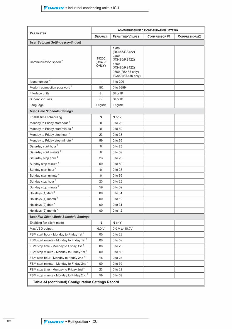
���
��������� ����������������������
������������������
PARAMETER AS-COMMISSIONED CONFIGURATION SETTING
DEFAULT PERMITTED VALUES COMPRESSOR #1 COMPRESSOR #2
User Setpoint Settings (continued)
Communication speed 7 19200
(RS485 ONLY)
1200 (RS485/RS422) 2400 (RS485/RS422) 4800 (RS485/RS422) 9600 (RS485 only) 19200 (RS485 only)
Ident number 7 1 1 to 200
Modem connection password 7 152 0 to 9999
Interface units SI SI or IP
Supervisor units SI SI or IP
Language English English
User Time Schedule Settings
Enable time scheduling N N or Y
Monday to Friday start hour 8 0 0 to 23
Monday to Friday start minute 8 0 0 to 59
Monday to Friday stop hour 8 23 0 to 23
Monday to Friday stop minute 8 59 0 to 59
Saturday start hour 8 0 0 to 23
Saturday start minute 8 0 0 to 59
Saturday stop hour 8 23 0 to 23
Sunday stop minute 8 59 0 to 59
Sunday start hour 8 0 0 to 23
Sunday start minute 8 0 0 to 59
Sunday stop hour 8 23 0 to 23
Sunday stop minute 8 59 0 to 59
Holidays (1) date 8 00 0 to 31
Holidays (1) month 8 00 0 to 12
Holidays (2) date 8 00 0 to 31
Holidays (2) month 8 00 0 to 12
User Fan Silent Mode Schedule Settings
Enabling fan silent mode N N or Y
Max VSD output 6.0 V 0.0 V to 10.0V
FSM start hour - Monday to Friday 1st 9 00 0 to 23
FSM start minute - Monday to Friday 1st 9 00 0 to 59
FSM stop time - Monday to Friday 1st 9 06 0 to 23
FSM stop minute - Monday to Friday 1st 9 00 0 to 59
FSM start hour - Monday to Friday 2nd 9 18 0 to 23
FSM start minute - Monday to Friday 2nd 9 00 0 to 59
FSM stop time - Monday to Friday 2nd 9 23 0 to 23
FSM stop minute - Monday to Friday 2nd 9 59 0 to 59
Table 34 (continued) Configuration Settings Record
ICU.pdf 204 26/01/2011 11:11:58
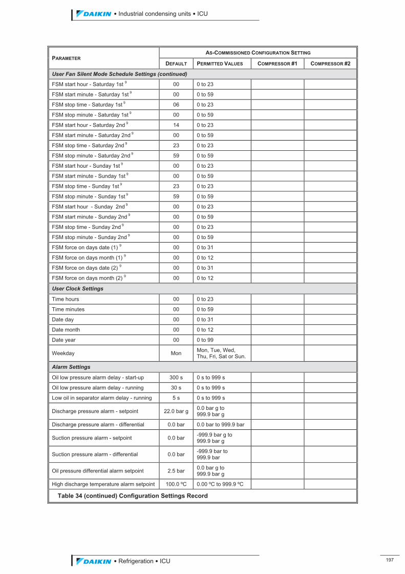
��������� ����������������������
������������������ ���
PARAMETER AS-COMMISSIONED CONFIGURATION SETTING
DEFAULT PERMITTED VALUES COMPRESSOR #1 COMPRESSOR #2
User Fan Silent Mode Schedule Settings (continued)
FSM start hour - Saturday 1st 9 00 0 to 23
FSM start minute - Saturday 1st 9 00 0 to 59
FSM stop time - Saturday 1st 9 06 0 to 23
FSM stop minute - Saturday 1st 9 00 0 to 59
FSM start hour - Saturday 2nd 9 14 0 to 23
FSM start minute - Saturday 2nd 9 00 0 to 59
FSM stop time - Saturday 2nd 9 23 0 to 23
FSM stop minute - Saturday 2nd 9 59 0 to 59
FSM start hour - Sunday 1st 9 00 0 to 23
FSM start minute - Sunday 1st 9 00 0 to 59
FSM stop time - Sunday 1st 9 23 0 to 23
FSM stop minute - Sunday 1st 9 59 0 to 59
FSM start hour - Sunday 2nd 9 00 0 to 23
FSM start minute - Sunday 2nd 9 00 0 to 59
FSM stop time - Sunday 2nd 9 00 0 to 23
FSM stop minute - Sunday 2nd 9 00 0 to 59
FSM force on days date (1) 9 00 0 to 31
FSM force on days month (1) 9 00 0 to 12
FSM force on days date (2) 9 00 0 to 31
FSM force on days month (2) 9 00 0 to 12
User Clock Settings
Time hours 00 0 to 23
Time minutes 00 0 to 59
Date day 00 0 to 31
Date month 00 0 to 12
Date year 00 0 to 99
Weekday Mon Mon, Tue, Wed, Thu, Fri, Sat or Sun.
Alarm Settings
Oil low pressure alarm delay - start-up 300 s 0 s to 999 s
Oil low pressure alarm delay - running 30 s 0 s to 999 s
Low oil in separator alarm delay - running 5 s 0 s to 999 s
Discharge pressure alarm - setpoint 22.0 bar g 0.0 bar g to 999.9 bar g
Discharge pressure alarm - differential 0.0 bar 0.0 bar to 999.9 bar
Suction pressure alarm - setpoint 0.0 bar -999.9 bar g to 999.9 bar g
Suction pressure alarm - differential 0.0 bar -999.9 bar to 999.9 bar
Oil pressure differential alarm setpoint 2.5 bar 0.0 bar g to 999.9 bar g
High discharge temperature alarm setpoint 100.0 ºC 0.00 ºC to 999.9 ºC
Table 34 (continued) Configuration Settings Record
ICU.pdf 205 26/01/2011 11:11:58
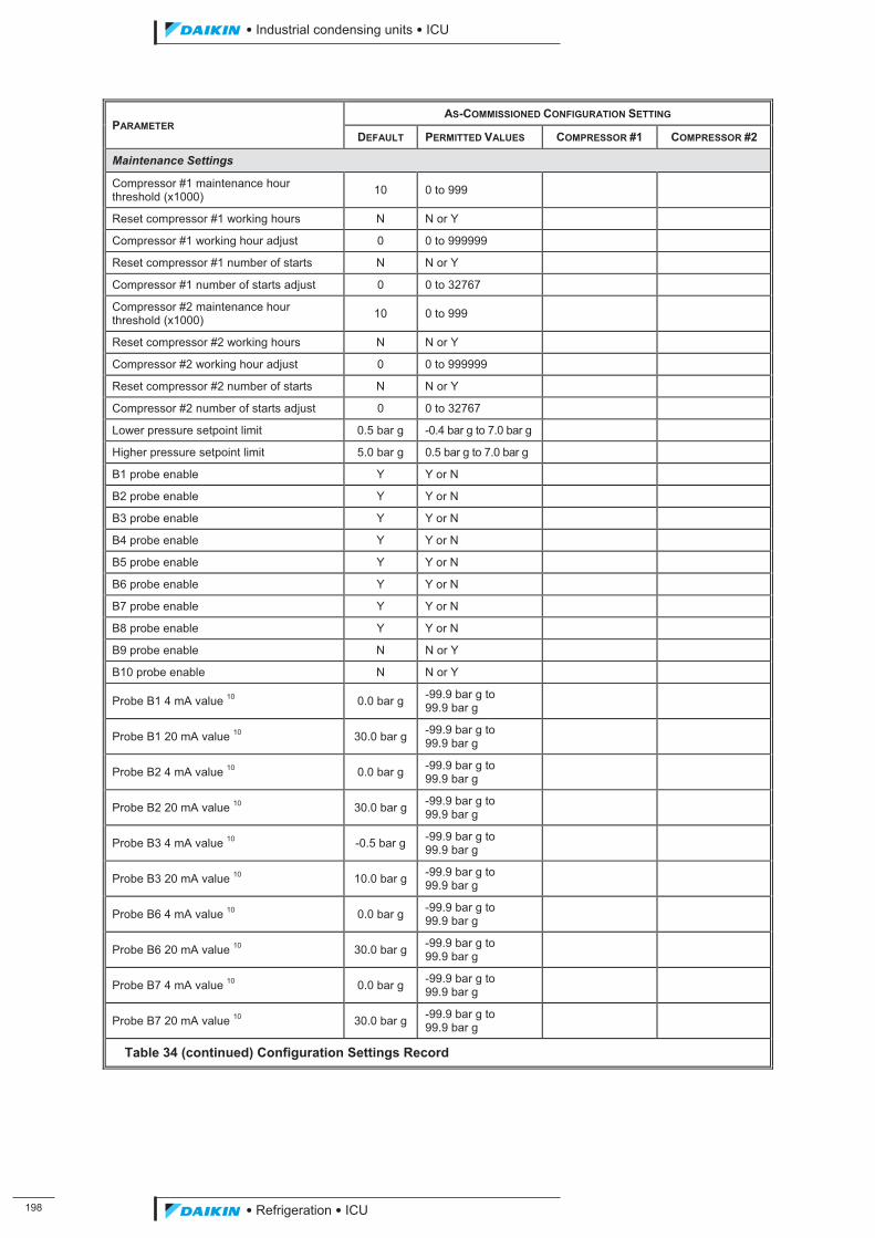
���
��������� ����������������������
������������������
PARAMETER AS-COMMISSIONED CONFIGURATION SETTING
DEFAULT PERMITTED VALUES COMPRESSOR #1 COMPRESSOR #2
Maintenance Settings
Compressor #1 maintenance hour threshold (x1000) 10 0 to 999
Reset compressor #1 working hours N N or Y
Compressor #1 working hour adjust 0 0 to 999999
Reset compressor #1 number of starts N N or Y
Compressor #1 number of starts adjust 0 0 to 32767
Compressor #2 maintenance hour threshold (x1000) 10 0 to 999
Reset compressor #2 working hours N N or Y
Compressor #2 working hour adjust 0 0 to 999999
Reset compressor #2 number of starts N N or Y
Compressor #2 number of starts adjust 0 0 to 32767
Lower pressure setpoint limit 0.5 bar g -0.4 bar g to 7.0 bar g
Higher pressure setpoint limit 5.0 bar g 0.5 bar g to 7.0 bar g
B1 probe enable Y Y or N
B2 probe enable Y Y or N
B3 probe enable Y Y or N
B4 probe enable Y Y or N
B5 probe enable Y Y or N
B6 probe enable Y Y or N
B7 probe enable Y Y or N
B8 probe enable Y Y or N
B9 probe enable N N or Y
B10 probe enable N N or Y
Probe B1 4 mA value 10 0.0 bar g -99.9 bar g to 99.9 bar g
Probe B1 20 mA value 10 30.0 bar g -99.9 bar g to 99.9 bar g
Probe B2 4 mA value 10 0.0 bar g -99.9 bar g to 99.9 bar g
Probe B2 20 mA value 10 30.0 bar g -99.9 bar g to 99.9 bar g
Probe B3 4 mA value 10 -0.5 bar g -99.9 bar g to 99.9 bar g
Probe B3 20 mA value 10 10.0 bar g -99.9 bar g to 99.9 bar g
Probe B6 4 mA value 10 0.0 bar g -99.9 bar g to 99.9 bar g
Probe B6 20 mA value 10 30.0 bar g -99.9 bar g to 99.9 bar g
Probe B7 4 mA value 10 0.0 bar g -99.9 bar g to 99.9 bar g
Probe B7 20 mA value 10 30.0 bar g -99.9 bar g to 99.9 bar g
Table 34 (continued) Configuration Settings Record
ICU.pdf 206 26/01/2011 11:11:58
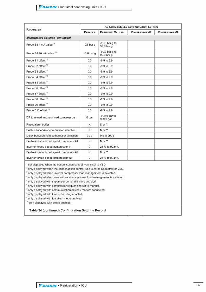
��������� ����������������������
������������������ ���
PARAMETER AS-COMMISSIONED CONFIGURATION SETTING
DEFAULT PERMITTED VALUES COMPRESSOR #1 COMPRESSOR #2
Maintenance Settings (continued)
Probe B8 4 mA value 10 -0.5 bar g -99.9 bar g to 99.9 bar g
Probe B8 20 mA value 10 10.0 bar g -99.9 bar g to 99.9 bar g
Probe B1 offset 10 0.0 -9.9 to 9.9
Probe B2 offset 10 0.0 -9.9 to 9.9
Probe B3 offset 10 0.0 -9.9 to 9.9
Probe B4 offset 10 0.0 -9.9 to 9.9
Probe B5 offset 10 0.0 -9.9 to 9.9
Probe B6 offset 10 0.0 -9.9 to 9.9
Probe B7 offset 10 0.0 -9.9 to 9.9
Probe B8 offset 10 0.0 -9.9 to 9.9
Probe B9 offset 10 0.0 -9.9 to 9.9
Probe B10 offset 10 0.0 -9.9 to 9.9
DP to reload and reunload compressors 0 bar -999.9 bar to 999.9 bar
Reset alarm buffer N N or Y
Enable supervisor compressor selection N N or Y
Delay between next compressor selection 30 s 0 s to 999 s
Enable inverter forced speed compressor #1 N N or Y
Inverter forced speed compressor #1 0 25 % to 99.9 %
Enable inverter forced speed compressor #2 N N or Y
Inverter forced speed compressor #2 0 25 % to 99.9 %
1 not displayed when the condensation control type is set to VSD. 2 only displayed when the condensation control type is set to Speedtroll or VSD. 3 only displayed when inverter compressor load management is selected. 4 only displayed when solenoid valve compressor load management is selected. 5 only displayed with supervisor demand limiting enabled. 6 only displayed with compressor sequencing set to manual. 7 only displayed with communication device / modem connected. 8 only displayed with time scheduling enabled. 9 only displayed with fan silent mode enabled. 10 only displayed with probe enabled.
Table 34 (continued) Configuration Settings Record
ICU.pdf 207 26/01/2011 11:11:58

Naamloze Vennootschap - Zandvoordestraat 300, B-8400 Oostende - Belgium - www.daikin.eu - BE 0412 120 336 - RPR Oostende
Daikin products are distributed by:
The present leaflet is drawn up by way of information only and does not constitute an offer binding upon
Daikin Europe N.V.. Daikin Europe N.V. has compiled the content of this leaflet to the best of its knowledge.
No express or implied warranty is given for the completeness, accuracy, reliability or fitness for particular
purpose of its content and the products and services presented therein. Specifications are subject to change
without prior notice. Daikin Europe N.V. explicitly rejects any liability for any direct or indirect damage, in
the broadest sense, arising from or related to the use and/or interpretation of this leaflet. All content is
copyrighted by Daikin Europe N.V.
Daikin Europe N.V. is participating in the EUROVENT
Certification Programme. Products are as listed in the
EUROVENT Directory of Certified Products.
Daikin’s unique position as a manufacturer of air
conditioning equipment, compressors and refrigerants
has led to its close involvement in environmental issues.
For several years Daikin has had the intention to become
a leader in the provision of products that have limited
impact on the environment. This challenge demands
the eco design and development of a wide range
of products and an energy management system,
resulting in energy conservation and a reduction of
waste.
CD
• 1
2/1
0 •
Co
pyr
igh
t D
aik
in
Pre
par
ed
in B
elg
ium
by
Lan
no
o (
ww
w.la
nn
oo
pri
nt.
be
), a
com
pan
y w
ho
se c
on
cern
for
the
en
viro
nm
en
t is
se
t in
th
e E
MA
S an
d IS
O 1
40
01
sys
tem
s.
Re
sp. E
d.:
Da
ikin
Eu
rop
e N
.V.,
Za
nd
vo
ord
est
raa
t 3
00
, B-8
40
0 O
ost
en
de
ICU.pdf 208 26/01/2011 11:11:58


![Refrigeration Basicswte[1]](https://img.pdfslide.tips/doc/110x75/577d380f1a28ab3a6b97010a/refrigeration-basicswte1.jpg)