Embed Size (px)
Citation preview
CIVIL ENGINEERING PORTFOLIO V.REKHA
CONTACT INFOEmail:
8897810935Address:
E-31 Ultra Tech TownshipTadipatri, BhogasamudramAnantapur district-515415
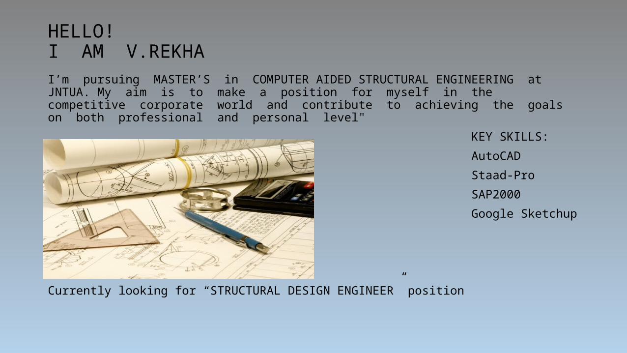
HELLO!I AM V.REKHAI’m pursuing MASTER’S in COMPUTER AIDED STRUCTURAL ENGINEERING at JNTUA. My aim is to make a position for myself in the competitive corporate world and contribute to achieving the goals on both professional and personal level"
KEY SKILLS:
AutoCAD
Staad-Pro
SAP2000
Google Sketchup
Currently looking for “STRUCTURAL DESIGN ENGINEER” position

ACADEMICMasters in Technology (CIVIL ENGINEERING)
Jawaharlal Nehru Technological University (JNTUA), Anantapur (Pursuing) Secured 68% in 1st yr.
Bachelors in Technology (CIVIL ENGINEERING) J.B.Institute of Engineering & Technology, Hyderabad, in 2014
Secured 70% marks.
Board of Intermediate (M.P.C) Sri Chaitanya Junior College, Hyderabad in 2010
Secured 86% marks.
Secondary Education (10th class)
L&T CSI PUBLIC School in 2008. Secured 78% marks.
MTEC PROJECT: Performance of lateral systems on tall buildings
• The advances in three-dimensional structural analysis and computing resources have allowed the efficient and safe design of increasingly taller structures. These structures are the consequence of increasing urban densification and economic viability. The present work aims to demonstrate the performance of building considered with outriggers, tube in tube, bundled system. • The building studied in this work is a reinforced concrete moment resisting
frame (G+40) designed for gravity and seismic using 1893:2002. And is studied using Non-linear time history analysis. These building models are analyzed, using SAP 2000 software, to the action of lateral forces employing non-linear dynamic approaches as per IS 1893 (Part I): 2002. The results of the analyses, in terms of lateral deformations, respective storey drifts and base shears are obtained and the conclusions are drawn thereof.
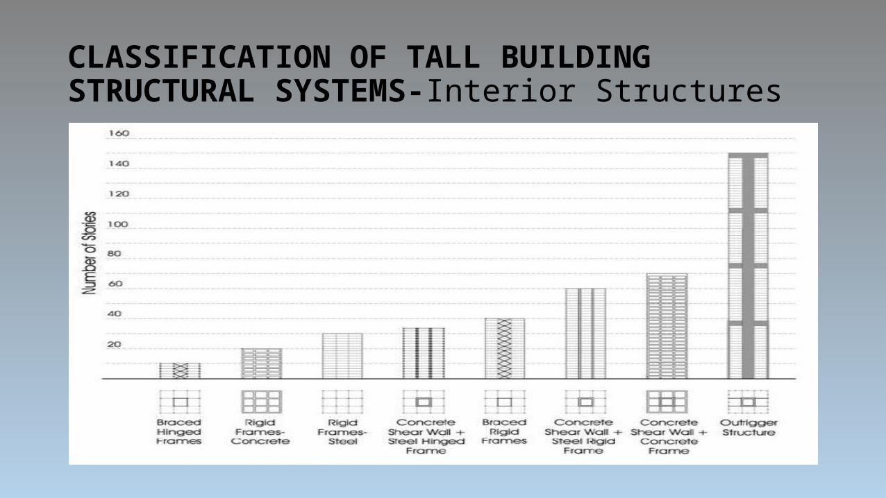
CLASSIFICATION OF TALL BUILDING STRUCTURAL SYSTEMS-Interior Structures
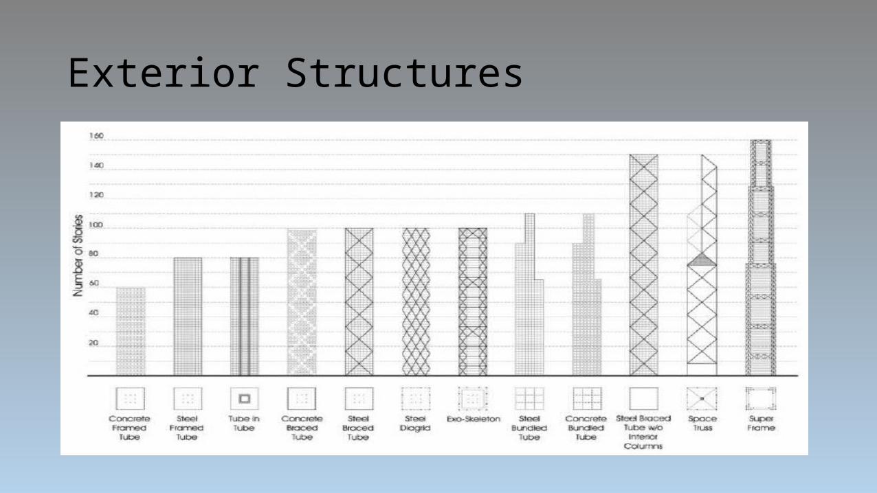
Exterior Structures
TUBE STRUCTURES• Tube design can be defined simply as a structural system that
prompts the building to behave as an equivalent hollow tube.Tubular systems are so efficient that in most cases the amount of structural material used is comparable to that used in conventionally framed buildings half the size.• Lateral loads were resisted by various connections, rigid or semi rigid,
supplemented where necessary by bracing and truss elements. • Further improvement in the structural economy was achieved by
engaging the exterior frame with the braced service core by tying the two systems together with outrigger and belt trusses. This was perhaps the beginning of tubular behavior since the engagement of the exterior columns is similar to that of the tube structure.

FRAMED TUBEThe method of achieving the tubular behavior by using closely spaced exterior columns connected by deep spandrel beams is the most used system because rectangular windows can be accommodated in this design. The framed tube requires large columns and deep beams Design of the tube structure assume a linear distribution and shear lag results in comer column experiencing greater stresses than central perimeter columns. This shear lag is a result of local deformation of beams which leads to a reduction of axial stress near the centre of the flange. The redistribution of these axial loads results in the corner perimeter columns becoming overstressed.
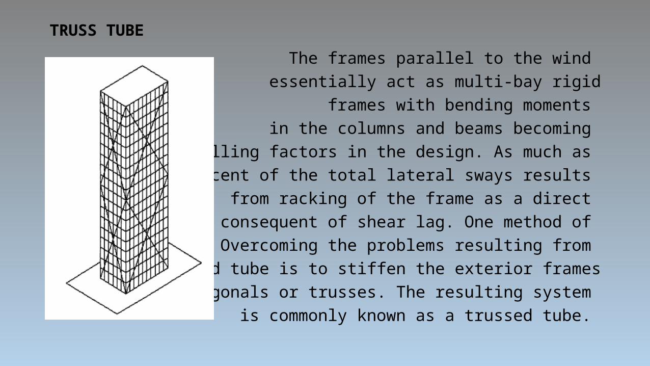
TRUSS TUBEThe frames parallel to the wind essentially act as multi-bay rigid frames with bending moments
in the columns and beams becoming controlling factors in the design. As much as 75 percent of the total lateral sways results
from racking of the frame as a direct consequent of shear lag. One method of Overcoming the problems resulting from
the framed tube is to stiffen the exterior frames with diagonals or trusses. The resulting system
is commonly known as a trussed tube.
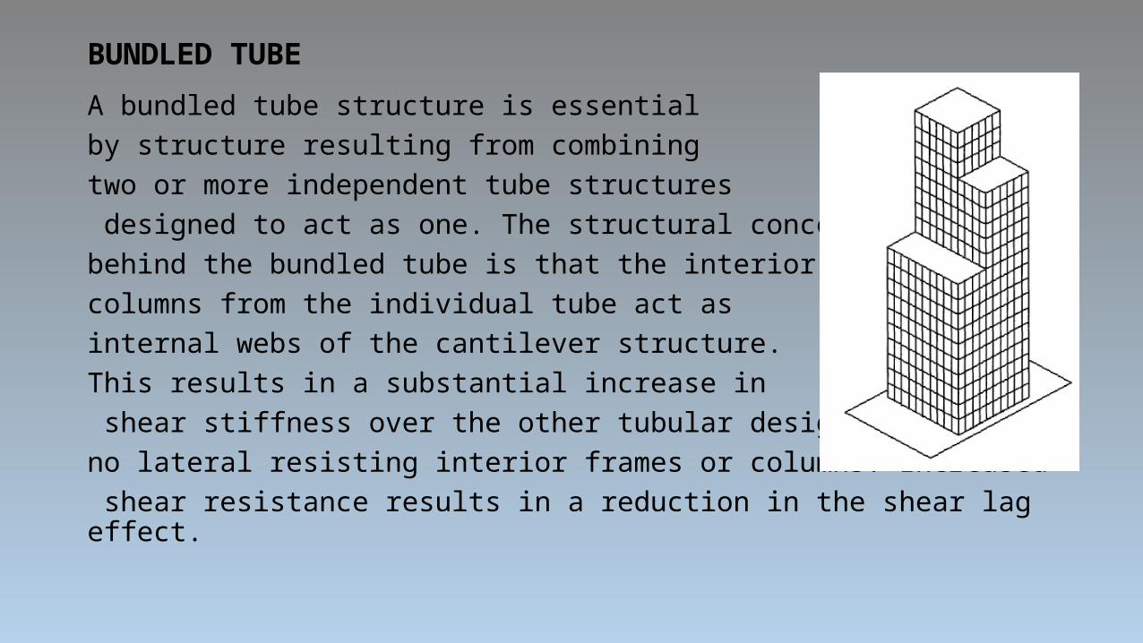
BUNDLED TUBEA bundled tube structure is essential by structure resulting from combining two or more independent tube structures designed to act as one. The structural concept behind the bundled tube is that the interior columns from the individual tube act as internal webs of the cantilever structure. This results in a substantial increase in shear stiffness over the other tubular designs with no lateral resisting interior frames or columns. Increased shear resistance results in a reduction in the shear lag effect.

NON LINEAR DIRECT INTEGRATION TIME HISTORY ANALYSIS IN SAP 2000
• Following are the general sequence of steps involved in performing NLTHA using SAP 2000 in the present study:• A two or three dimensional model that represents the overall structural behaviour created.• For reinforced concrete elements the appropriate reinforcement is provided for the cross sections.• Frame hinge properties are defined and assigned to the frame elements.• Gravity loads composed of dead loads and a specified proportion of live load is assigned as seismic weight to
the structure.• Free vibration un-damped modal analysis is performed to make note of the frequencies and time periods of the
structure.• The time history function from a file is selected and the time history function is defined.• The non-linear direct integration time history load cases are defined by assigning the ground acceleration time
history function as loading in X and Y directions. and by assigning proportional damping • NLTHA is set to run.• After the analysis is completed the displacement pattern of the structure is studied and inter story drifts are
calculated.• The hinge pattern is studied to assess the performance of the structure.• The other responses such as base shear, member forces, and response spectrum curves are noted.
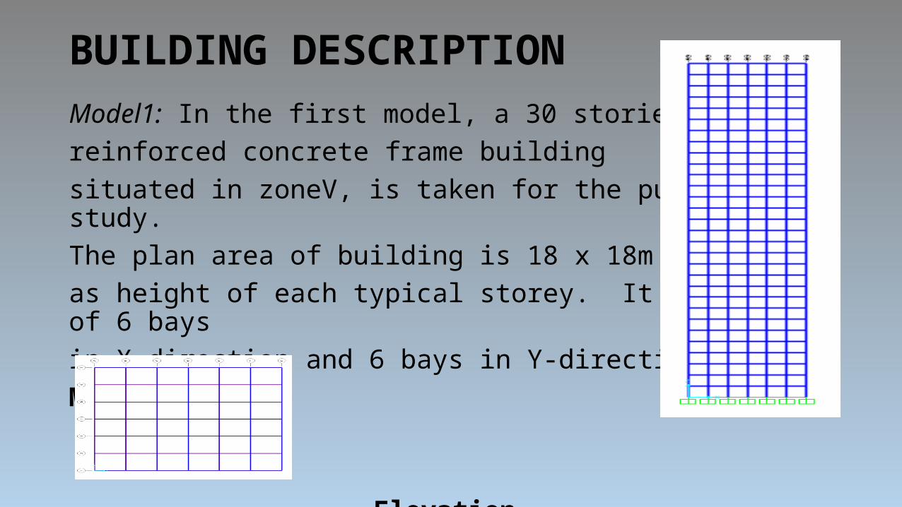
BUILDING DESCRIPTIONModel1: In the first model, a 30 storiedreinforced concrete frame building situated in zoneV, is taken for the purpose of study.The plan area of building is 18 x 18m with 3m as height of each typical storey. It consists of 6 bays in X-direction and 6 bays in Y-direction.Model Plan
Elevation
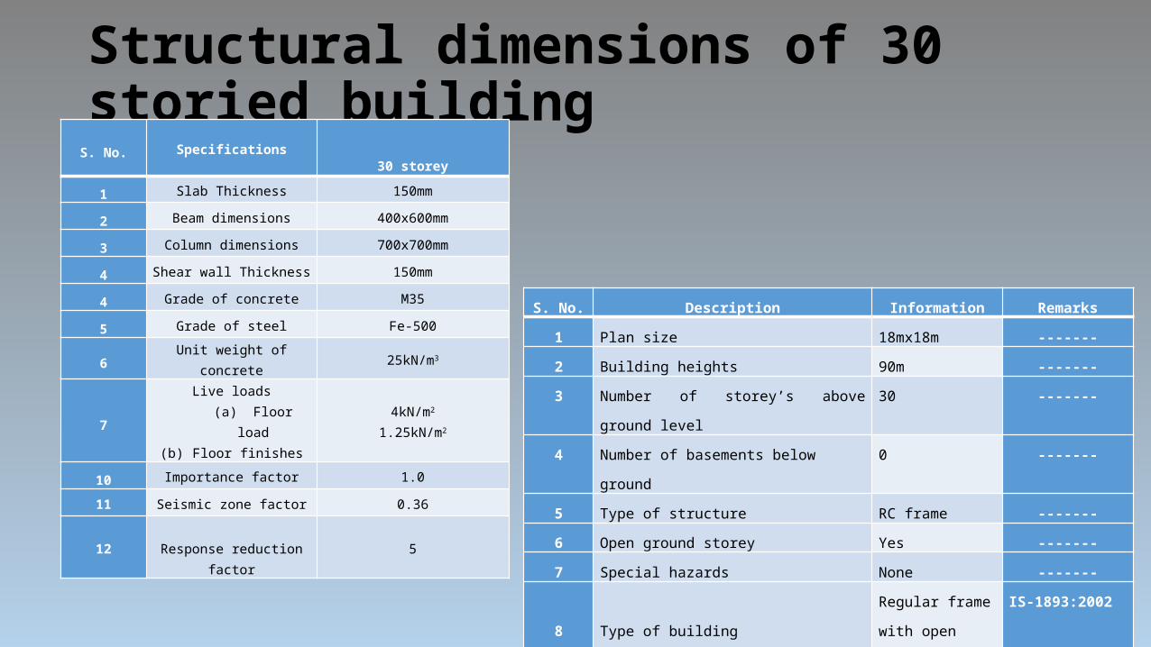
Structural dimensions of 30 storied building
S. No. Description Information Remarks
1 Plan size 18mx18m -------
2 Building heights 90m -------
3 Number of storey’s above ground level 30 -------
4 Number of basements below ground 0 -------
5 Type of structure RC frame -------
6 Open ground storey Yes -------
7 Special hazards None -------
8
Type of building
Regular frame with open ground storey
IS-1893:2002 Clause 7.1
9 Horizontal floor system Beams & Slabs -------
10 Software used SAP 2000 -------
S. No. Specifications 30 storey
1 Slab Thickness 150mm
2 Beam dimensions 400x600mm
3 Column dimensions 700x700mm
4 Shear wall Thickness 150mm
4 Grade of concrete M35
5 Grade of steel Fe-500
6 Unit weight of concrete 25kN/m3
7Live loads
(a) Floor load(b) Floor finishes
4kN/m2
1.25kN/m2
10 Importance factor 1.0
11 Seismic zone factor 0.36
12 Response reduction factor 5
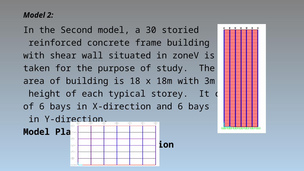
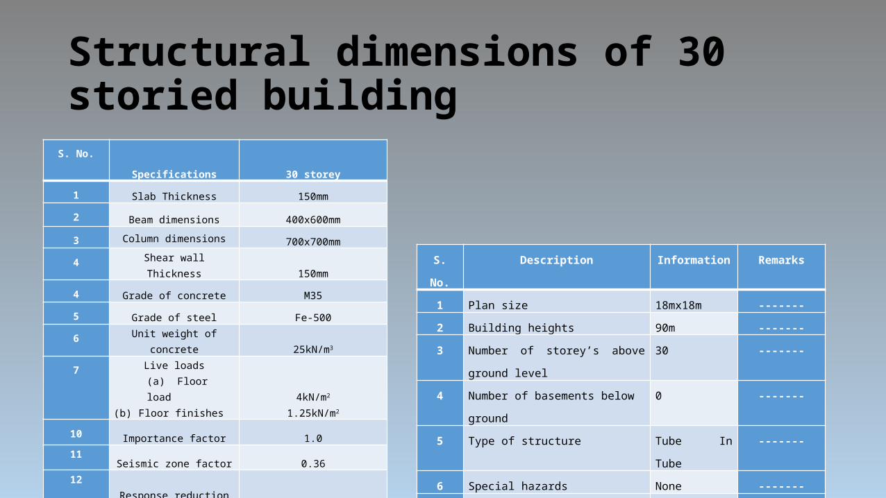
Model 2:In the Second model, a 30 storied reinforced concrete frame building with shear wall situated in zoneV is taken for the purpose of study. The planarea of building is 18 x 18m with 3m as height of each typical storey. It consists of 6 bays in X-direction and 6 bays in Y-direction. Model Plan
Elevation

Structural dimensions of 30 storied building
S. No. Specifications 30 storey
1 Slab Thickness 150mm
2 Beam dimensions 400x600mm
3 Column dimensions 700x700mm
4 Shear wall Thickness 150mm
4 Grade of concrete M35
5 Grade of steel Fe-500
6 Unit weight of concrete 25kN/m3
7Live loads
(a) Floor load(b) Floor finishes
4kN/m2
1.25kN/m2
10 Importance factor 1.0
11 Seismic zone factor 0.36
12 Response reduction factor 5
S. No. Description Information Remarks1 Plan size 18mx18m -------2 Building heights 90m -------3 Number of storey’s above ground level 30 -------4 Number of basements below ground 0 -------5 Type of structure RC frame with
shear wall-------
6 Special hazards None ------- 7
Type of building
Regular frame with open ground storey
IS-1893:2002 Clause 7.1
8 Horizontal floor system Beams & Slabs -------9 Software used SAP 2000 -------
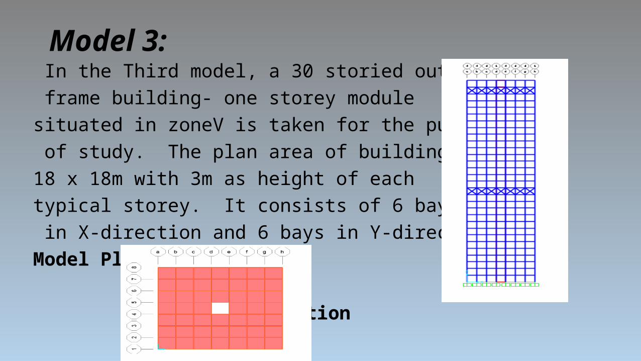
Model 3: In the Third model, a 30 storied outrigger frame building- one storey module situated in zoneV is taken for the purpose of study. The plan area of building is 18 x 18m with 3m as height of each typical storey. It consists of 6 bays in X-direction and 6 bays in Y-direction. Model Plan
Elevation
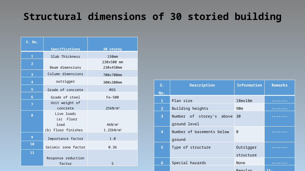
Structural dimensions of 30 storied building
S. No.
Specifications
30 storey
1Slab Thickness 150mm
2Beam dimensions
230x500 mm230x450mm
3 Column dimensions 700x700mm4 outrigger 300x300mm5
Grade of concrete M356
Grade of steel Fe-5007
Unit weight of concrete 25kN/m3
8 Live loads(a) Floor load
(b) Floor finishes4kN/m2
1.25kN/m2
9Importance factor 1.0
10Seismic zone factor 0.36
11 Response reduction factor 5
S. No. Description Information Remarks1 Plan size 18mx18m -------2 Building heights 90m -------3 Number of storey’s above ground level 30 -------4 Number of basements below ground 0 -------5 Type of structure Outrigger
structure-------
6 Special hazards None ------- 7
Type of building
Regular frame with open ground storey
IS-1893:2002 Clause 7.1
8 Horizontal floor system Beams & Slabs -------9 Software used SAP 2000 -------

Model 4: In the fourth model, a 30 storied Tube in Tube building situated in zoneV is taken for the purpose of study. The plan area of building is 18 x 18m with 3m as height of each typical storey. It consists of 6 bays in X-direction and 6 bays in Y-direction.Model Plan
Elevation
Structural dimensions of 30 storied building
S. No.
Specifications
30 storey
1Slab Thickness 150mm
2Beam dimensions 400x600mm
3 Column dimensions 700x700mm4 Shear wall Thickness 150mm4
Grade of concrete M355
Grade of steel Fe-5006
Unit weight of concrete 25kN/m3
7 Live loads(a) Floor load
(b) Floor finishes4kN/m2
1.25kN/m2
10Importance factor 1.0
11Seismic zone factor 0.36
12 Response reduction factor 5
S. No. Description Information Remarks1 Plan size 18mx18m -------2 Building heights 90m -------3 Number of storey’s above ground level 30 -------4 Number of basements below ground 0 -------5 Type of structure Tube In Tube -------6 Special hazards None ------- 7
Type of building
Regular frame with open ground storey
IS-1893:2002 Clause 7.1
8 Horizontal floor system Beams & Slabs -------9 Software used SAP 2000 -------
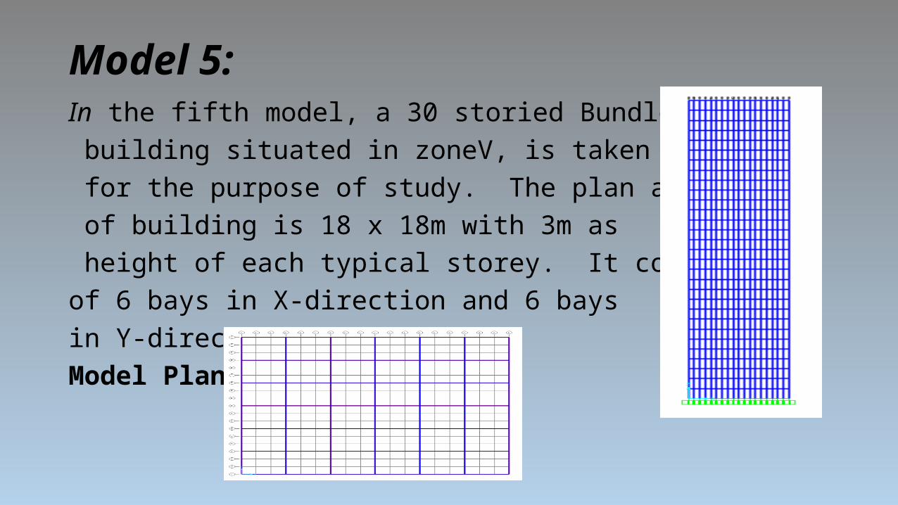
Model 5:In the fifth model, a 30 storied Bundled Tube building situated in zoneV, is taken for the purpose of study. The plan area of building is 18 x 18m with 3m as height of each typical storey. It consists of 6 bays in X-direction and 6 bays in Y-direction.Model Plan
Elevation
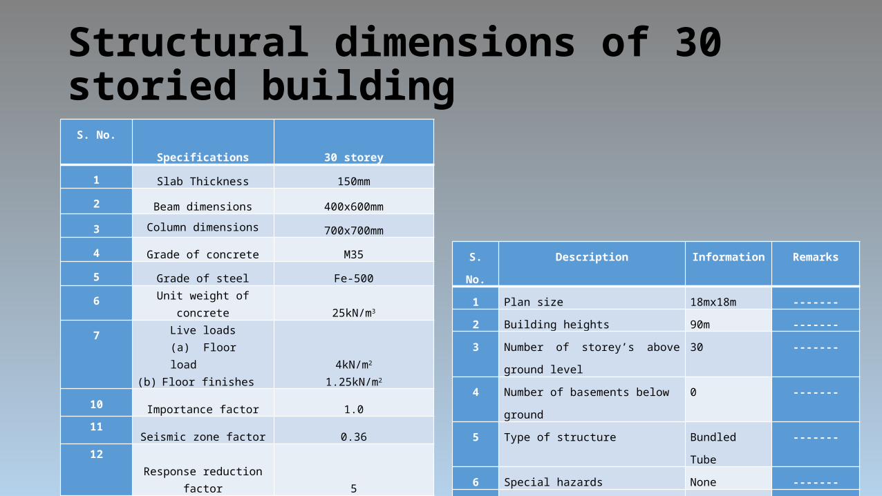
Structural dimensions of 30 storied building
S. No.
Specifications
30 storey
1Slab Thickness 150mm
2Beam dimensions 400x600mm
3 Column dimensions 700x700mm4
Grade of concrete M355
Grade of steel Fe-5006
Unit weight of concrete 25kN/m3
7 Live loads(a) Floor load
(b) Floor finishes4kN/m2
1.25kN/m2
10Importance factor 1.0
11Seismic zone factor 0.36
12 Response reduction factor 5
S. No. Description Information Remarks1 Plan size 18mx18m -------2 Building heights 90m -------3 Number of storey’s above ground level 30 -------4 Number of basements below ground 0 -------5 Type of structure Bundled Tube -------6 Special hazards None ------- 7
Type of building
Regular frame with open ground storey
IS-1893:2002 Clause 7.1
8 Horizontal floor system Beams & Slabs -------9 Software used SAP 2000 -------

RESULTS
0 5 10 15 20 25 30 350
100
200
300
400
500
600
RCCBUNDLED TUBE IN TUBE out-riggerSHEAR WALL
storeys
disp
lace
men
t
Displacement of Models Modal Periods Moments
0 5 10 15 20 25 30 350.0
1.0
2.0
3.0
4.0
5.0
6.0
7.0
8.0
9.0
10.0
RCCBUNDLED TUBE IN TUBE OUTRIGGER30 RCC SHEAR WALL
STOREYS
DR
IFT
Storey
-30
Storey
-26
Storey
-22
Storey
-18
Storey
-14
Storey
-10
Storey
-6
Storey
-20
1000
2000
3000
4000
5000
6000
7000
8000
9000
10000
TUBE IN TUBEBUNDLED TUBEoutriggerRCC WITH SHEARWALLRCC

Time period Base Shear BaseMoment
0 2 4 6 8 10 12 140
1
2
3
4
5
6
7
RCC
BUNDLED
TUBE IN TUBE
outrigger
SHEAR WALL
MODES
TIM
E P
ER
IOD
S
BASE SHEAR0
1000
2000
3000
4000
5000
6000
7000
8000
9000
10000
RCCBUNDLEDTUBE IN TUBEOUTRIGGERRCC SHEAR WALL
10
100000
200000
300000
400000
500000
600000
700000
800000
900000
RCCBUNDLEDTUBE IN TUBEOUTRIGGERRCC SHEAR WALL
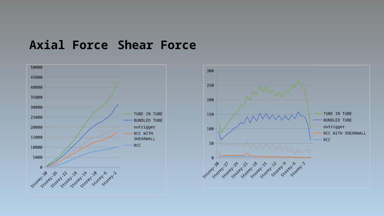
Axial Force Shear Force
Storey
-30
Storey
-27
Storey
-24
Storey
-21
Storey
-18
Storey
-15
Storey
-12
Storey
-9
Storey
-6
Storey
-30
5000
10000
15000
20000
25000
30000
35000
40000
45000
50000
TUBE IN TUBEBUNDLED TUBEoutriggerRCC WITH SHEARWALLRCC
Storey
-30
Storey
-28
Storey
-26
Storey
-24
Storey
-22
Storey
-20
Storey
-18
Storey
-16
Storey
-14
Storey
-12
Storey
-10
Storey
-8
Storey
-6
Storey
-4
Storey
-20
50
100
150
200
250
300
TUBE IN TUBEBUNDLED TUBEoutriggerRCC WITH SHEARWALLRCC
CONCLUSIONS
The overall results suggested that bundled tube is excellent seismic control for high-rise symmetric Buildings. As we have seen, the bundled ,diagrids, the latest mutation of tubular structures, has in addition to strength and aesthetics, that extra quality of geometric versatility, making it the most suited structural system to this respect.
Thus the bundled tube and outrigger, with an optimal combination of qualities of aesthetic expression, structural efficiency and geometric versatility is indeed the language of the modern day builder.


![Karad Rekha - 2014-15lsgkerala.in/kolazhypanchayat/files/2014/11/padhathi-rekha-part-1.pdfDj cho{µ≥ saº¿, hm¿Uv 2 kpP tKm]n saº¿, hm¿Uv 11 Cµnc kptcjv saº¿, hm¿Uv 3 Fw.Sn](https://img.pdfslide.tips/doc/110x75/5f80e81e6442af33325ce424/karad-rekha-2014-dj-choa-sa-hmuv-2-kpp-tkmn-sa-hmuv-11-cnc.jpg)