Embed Size (px)
Citation preview
REPORT OF SUBSURFACE INVESTIGATION ANDGEOTECHNICAL ENGINEERING SERVICES
Proposed Soundside Boardwalk ExpansionDuck, North Carolina
G E T PROJECT NO: EC10-260GNovember 17, 2010
Prepared for
VHB, Inc.5544 Greenwich Rd.
Suite 302Virginia Beach, VA 23462
ATTN: MR. Chris DeWitt, AICP
Prepared by
GET Solutions, Inc.
106 Capital Trace Unit E, Elizabeth City, NC 27909 ��������252-335-9765 ����252-335-9766
November 17, 2010
TO: VHB, Inc.5544 Greenwich Rd.Suite 302Virginia Beach, VA 23462
Attn: Mr. Chris DeWitt, AICP
RE: Report of Subsurface Investigation and Geotechnical EngineeringProposed Soundside Boardwalk ExpansionDuck, North CarolinaGET Project No: EC10-260G
Dear Mr. DeWitt:
In compliance with your instructions, we have completed our Subsurface Investigation and Geotechnical Engineering Services for the above referenced project. The results of this study, together with our recommendations, are presented in this report.
Often, because of design and construction details that occur on a project, questions arise concerning subsurface conditions. G E T Solutions, Inc. would be pleased to continue its role as Geotechnical Engineer during the project implementation.
Thank you for the opportunity to work with you on this project. We trust that the information contained herein meets your immediate need, and should you have any questions or if we could be of further assistance, please do not hesitate to contact us.
Respectfully Submitted,G E T Solutions, Inc.
Gerald W. Stalls Jr., P.E.Senior Project EngineerNC Reg. # 034336
Camille A. Kattan, P.E. Principal EngineerNC Reg. # 014103
Copies: (1) Client
106 Capital Trace Unit E � Elizabeth City, NC 27909 � Phone: (252)335-9765 � Fax: (252)[email protected]
Report of Subsurface Investigation and Geotechnical Engineering Services November 17, 2010Proposed Soundside Boardwalk ExpansionDuck, North CarolinaGET Project No: EC10-260G
i
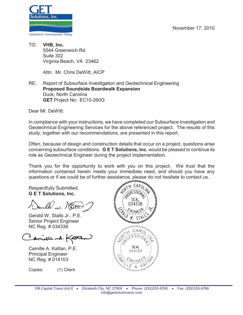
EXECUTIVE SUMMARY
The project site is located along the east shoreline of the Currituck Sound in the Town of Duck, North Carolina. The construction at the site is planned to consist of building a new expansion of the existing boardwalk. The boardwalk is to consist of wood frame construction with a width of about 10 feet and a finished deck elevation of about 7 feet MSL. The proposed boardwalk is to be supported by round timber piles driven to depths ranging from 15 to 20 feet below the varying existing site grade elevations in order to develop the allowable compression capacity of about 15 tons.
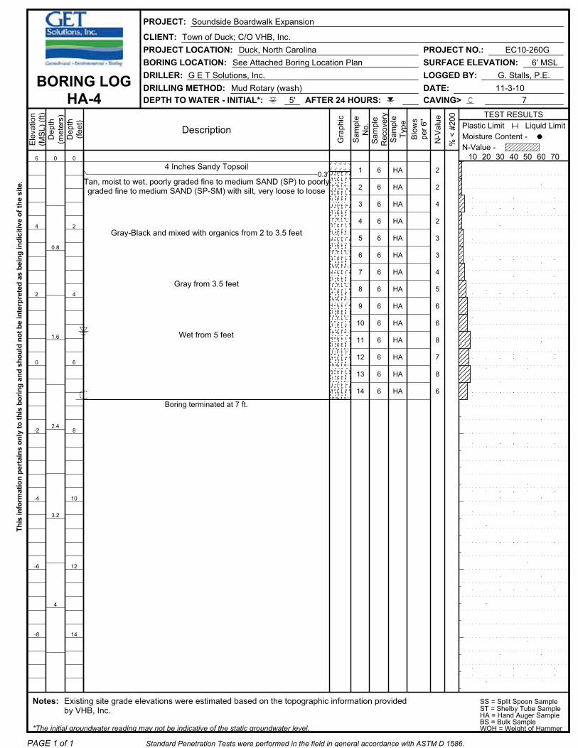
Our field exploration program included six (6) 25-foot deep SPT borings, four (4) 3- to 7-foot deep hand auger borings with Dynamic Cone Penetrometer (DCP) tests, and four (4) 5-foot deep DCP tests performed by G E T Solutions, Inc. along the alignment of the proposed boardwalk expansions. A brief description of the natural subsurface soil conditions is tabulated on the following page:
Note (1) SPT = Standard Penetration Test, N-Values in Blows-per-foot.Note (2): These depths represent the boring termination depths ranging from 3 to 25 feet below the existing site grade elevations at the relevant boring locations.
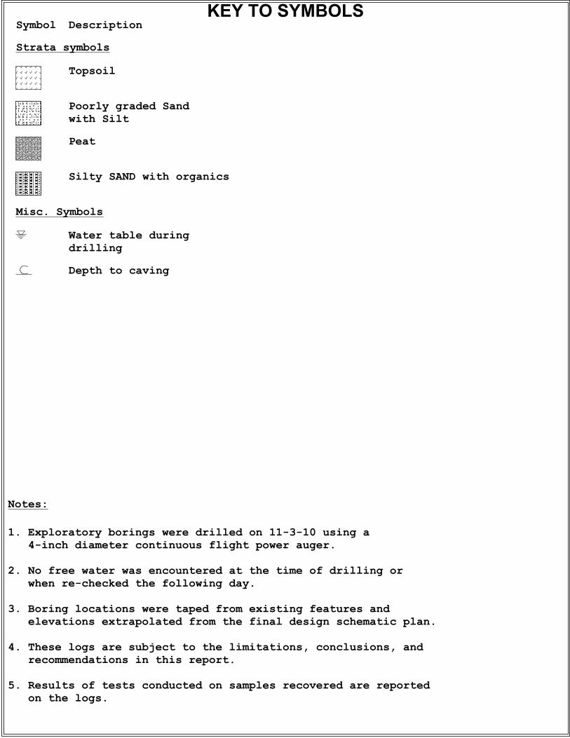
The groundwater level encountered at the location of borings B-1 through B-6 and HA-1 through HA-4 was observed through the wetness of the recovered soil samples during the drilling operations. The initial groundwater table was measured to occur at depths ranging from 1.5 to 5 feet below current grades at the boring locations. The observed groundwater levels were noted to correspond to elevations generally ranging from about 0.5 to 1.5 feet (MSL). The varying groundwater levels are anticipated to be effected by the existing topography of the project site. The boreholes were backfilled uponcompletion for safety considerations. As such, the reported groundwater levels may not be indicative of the static groundwater level.
AVERAGE DEPTH (Feet) STRATUM DESCRIPTION
RANGES OFSPT(1) N-VALUES
Borings: B-1 through B-6 and HA-1 through HA-40to
0.18 – 3.5TOPSOIL and/or PEAT (PT)
0to
3 – 25(2)I SAND (SP, SP-SM, SM) with varying amounts of silt 2 to 32
2 – 3.5to
3.5 - 5IA SAND (SP-SM, SM) with varying amounts of organics
and/or PEAT; Borings B-1, B-5, B-6, HA-2, and HA-4 1 to 7
3 - 5to
3.5 to 4IB Silty Fibrous PEAT (PT) with varying amounts of sand;
Borings B-3, HA-1 2 to 3

Report of Subsurface Investigation and Geotechnical Engineering Services November 17, 2010Proposed Soundside Boardwalk ExpansionDuck, North CarolinaGET Project No: EC10-260G
ii
The following preliminary evaluations and recommendations were developed based on our field exploration and laboratory-testing program:
� Field testing program during construction to include test and production pile testing and monitoring, and/or vibration monitoring. All other applicable testing, inspections, and evaluations should be performed as indicated in the North Carolina State Building Code (2009 International Building Code with North Carolina Amendments).
� It is anticipated that deep foundations comprised of round timber piles (with a minimum tip diameter of 8-inches) driven to pile tip elevations ranging from about -10 feet to -17 feet MSL will develop allowable compression capacities on the order of about 10 tons, respectively. The pile foundations should be installed and tested to ultimate capacities (2.25 times the allowable capacities) to account for negative skin friction loads.
� It is anticipated that the total butt settlements (including elastic shortening) will not exceed about ½-inch, which is the settlement necessary to mobilize the soil/pile capacity in combination with the pile tip settlements due to the stress increase in the underlying soils.
� It is recommended that a test pile program be implemented in order to establish the criteria for pile installation including the development of final tip elevations and to confirm that the contractor’s equipment and installation methods are acceptable. Once the test pile program has been successfully completed, the geotechnical engineer should observe all production piles to verify that their installation is being performed in accordance with the previously derived pile driving criteria.
� Proposed structures should be designed based on a site seismic classification of “D”, based on the results of the 25-foot deep SPT borings performed at this site, our experience in the project area, and the requirements provided in provided in the North Carolina State Building Code (2009 International Building Code with North Carolina Amendments).
This summary briefly discusses some of the major topics mentioned in the attached report. Accordingly, this report should be read in its entirety to thoroughly evaluate the contents.

20
TABLE OF CONTENTS page 1 of 1
EXECUTIVE SUMMARY .............................................................................................................i
1.0 PROJECT INFORMATION.............................................................................................1
1.1 Project Authorization...........................................................................................11.2 Project Description..............................................................................................11.3 Purpose and Scope of Services .........................................................................1
2.0 FIELD AND LABORATORY PROCEDURES................................................................2
2.1 Field Exploration .................................................................................................22.2 Laboratory Testing ..............................................................................................4
3.0 SITE AND SUBSURFACE CONDITIONS .....................................................................4
3.1 Site Location and Description .............................................................................43.2 Subsurface Soil Conditions.................................................................................53.3 Groundwater Information ....................................................................................6
4.0 EVALUATION AND RECOMMENDATIONS .................................................................7
4.1 Clearing and Grading..........................................................................................74.2 Pile Settlement - Preliminary...............................................................................84.3 Timber Piles ........................................................................................................84.4 Pile Installation Monitoring – Pre-Augered or Jetted Piles .................................94.5 Test Piles ..........................................................................................................104.6 Establishing Pile Driving Criteria – Driven Piles ...............................................114.7 Pile Installation Monitoring ................................................................................114.8 Adjacent Structures – Driven Piles ...................................................................124.9 Seismic Evaluation............................................................................................12
5.0 CONSTRUCTION CONSIDERATIONS .......................................................................12
5.1 Drainage and Groundwater Concerns..............................................................125.2 Excavations.......................................................................................................13
6.0 REPORT LIMITATIONS ...............................................................................................13
APPENDIX I BORING LOCATION PLANAPPENDIX II BORING LOGSAPPENDIX III GENERALIZED SOIL PROFILEAPPENDIX IV CLASSIFICATION SYSTEM FOR SOIL EXPLORATION

Report of Subsurface Investigation and Geotechnical Engineering Services November 17, 2010Proposed Soundside Boardwalk ExpansionDuck, North CarolinaGET Project No: EC10-260G
1
1.0 PROJECT INFORMATION
1.1 Project Authorization
G E T Solutions, Inc. has completed our Geotechnical Engineering study for the Phase I and Phase II portions of the proposed Soundside Boardwalk Expansion project. The Geotechnical Engineering Services were conducted in general accordance with G E T Solutions, Inc. Proposal No. PEC10-242G, dated October 15, 2010. Authorization to proceed with the services was received in the form of an email from Mr. Chris DeWitt with VHB, Inc. on the date of October 26, 2010.
1.2 Project Description
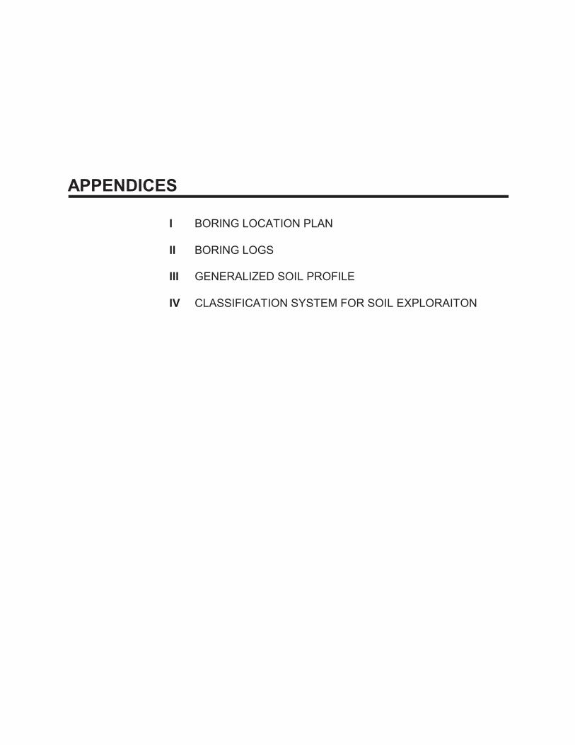
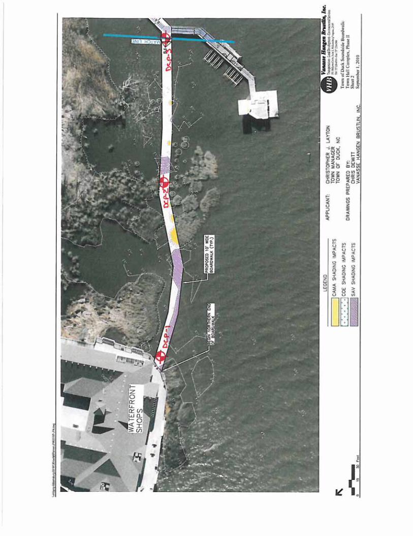
This development at this site is to include the construction of an expansion to the existingsoundside boardwalk, which is to be performed in two (2) phases. Phase I will extend from the north end of the existing boardwalk to approximately 230 feet north of the southwest retail building in the “Wee Winks Square” shopping center. Additionally, Phase I will also include replacing the existing pier located north of the “Kitty Hawk Kites” retail store and an extension of the pier to approximately 340 feet to the north. Phase II will extend from the south end of the existing boardwalk to the existing pier located west of the “Wings” retail store.
The new boardwalk will have an approximate width of 10 feet, a finished deck elevation of 7 feet MSL, and will be constructed of wood framing. The boardwalk will be supported by a deep foundation system comprised of round timber piles driven to a depth of about 15 feet below the existing site grade elevations and/or mud-line elevations. The pile foundation loads associated with the boardwalks were not known at this time. However, based on our experience with the design of the existing bulkhead at this site and other similar projects, the maximum axial pile foundation loads are not expected to exceed about 15 tons in compression.
If any of the noted information is incorrect or has changed, please inform G E T Solutions, Inc. so that we may amend the recommendations presented in this report, if appropriate.
1.3 Purpose and Scope of Services
The purpose of this study was to obtain information on the general subsurface conditions at the proposed project site. The subsurface conditions encountered were then evaluated with respect to the available project characteristics. In this regard, engineering assessments for the following items were formulated:
1. General assessment of the soils revealed by the borings performed at the proposed development.
Report of Subsurface Investigation and Geotechnical Engineering Services November 17, 2010Proposed Soundside Boardwalk ExpansionDuck, North CarolinaGET Project No: EC10-260G
2
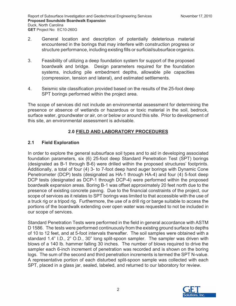
2. General location and description of potentially deleterious material encountered in the borings that may interfere with construction progress or structure performance, including existing fills or surficial/subsurface organics.
3. Feasibility of utilizing a deep foundation system for support of the proposed boardwalk and bridge. Design parameters required for the foundation systems, including pile embedment depths, allowable pile capacities (compression, tension and lateral), and estimated settlements.
4. Seismic site classification provided based on the results of the 25-foot deep SPT borings performed within the project area.
The scope of services did not include an environmental assessment for determining the presence or absence of wetlands or hazardous or toxic material in the soil, bedrock, surface water, groundwater or air, on or below or around this site. Prior to development of this site, an environmental assessment is advisable.
2.0 FIELD AND LABORATORY PROCEDURES
2.1 Field Exploration
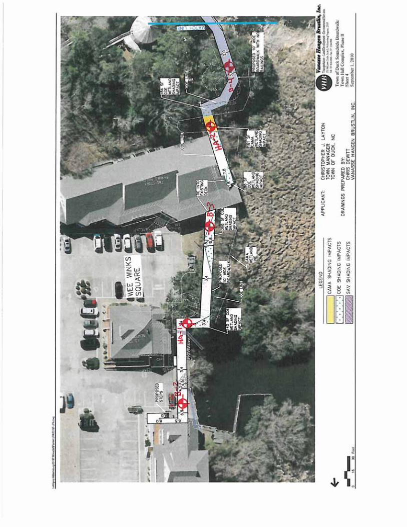
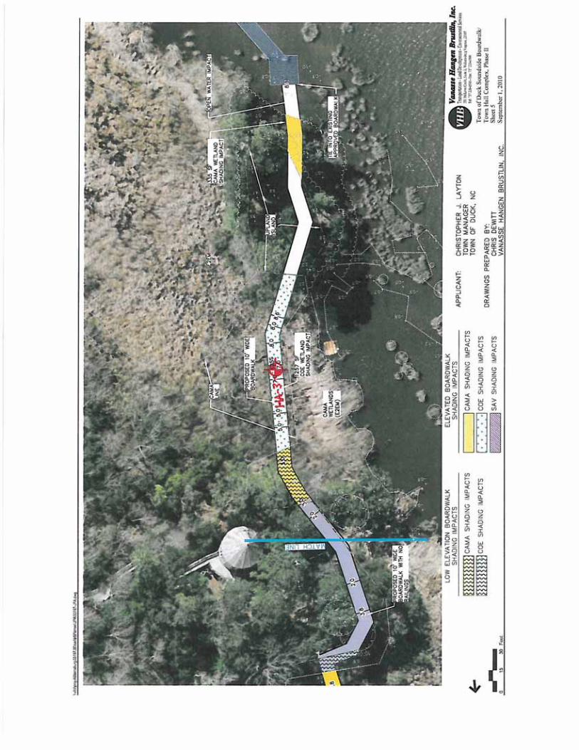
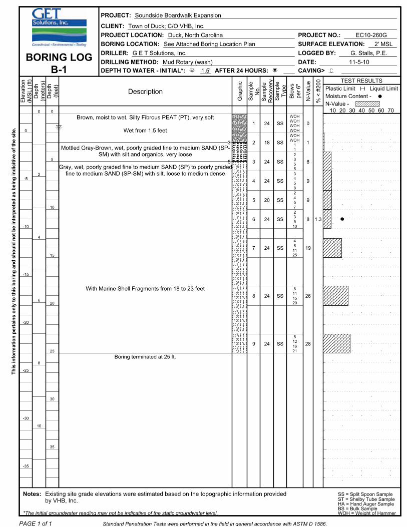
In order to explore the general subsurface soil types and to aid in developing associated foundation parameters, six (6) 25-foot deep Standard Penetration Test (SPT) borings (designated as B-1 through B-6) were drilled within the proposed structures’ footprints. Additionally, a total of four (4) 3- to 7-foot deep hand auger borings with Dynamic Cone Penetrometer (DCP) tests (designated as HA-1 through HA-4) and four (4) 5-foot deep DCP tests (designated as DCP-1 through DCP-4) were performed within the proposed boardwalk expansion areas. Boring B-1 was offset approximately 20 feet north due to the presence of existing concrete paving. Due to the financial constraints of the project, our scope of services as it relates to SPT borings was limited to that accessible with the use of a truck rig or a tripod rig. Furthermore, the use of a drill rig or barge suitable to access the portions of the boardwalk extending over open water was requested to not be included in our scope of services.
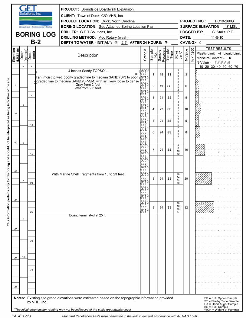
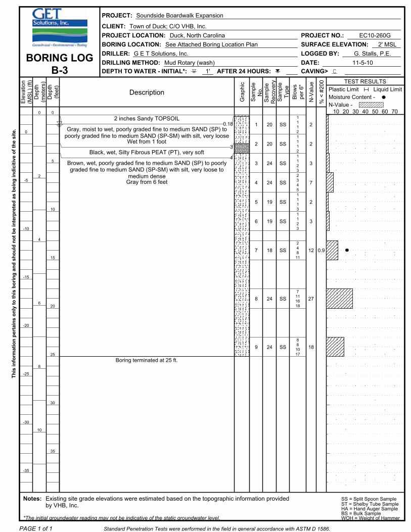
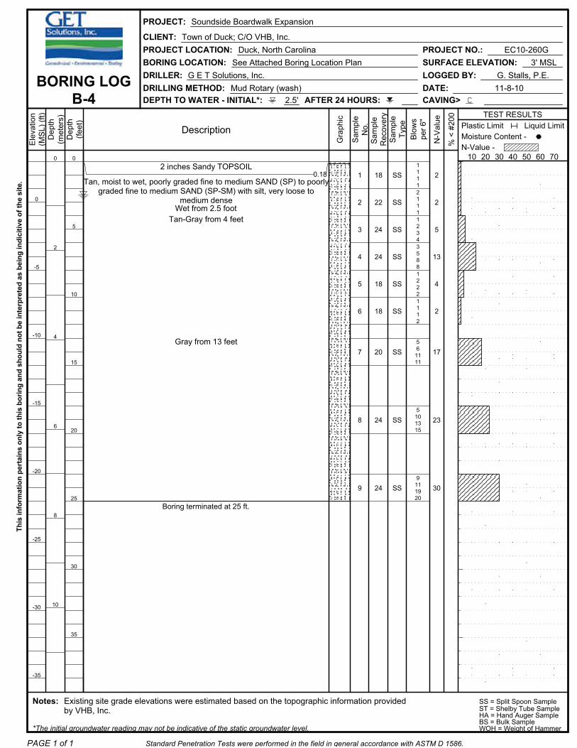
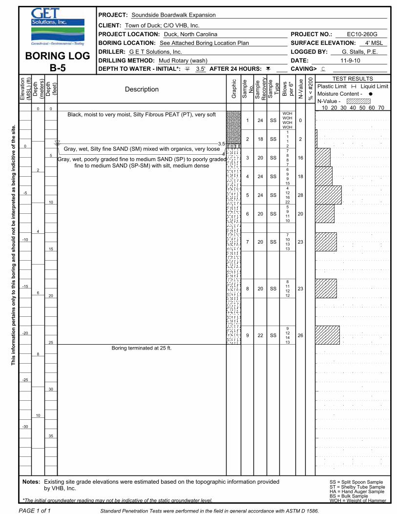
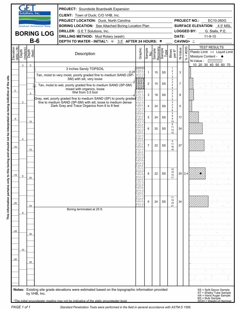
Standard Penetration Tests were performed in the field in general accordance with ASTM D 1586. The tests were performed continuously from the existing ground surface to depths of 10 to 12 feet, and at 5-foot intervals thereafter. The soil samples were obtained with a standard 1.4” I.D., 2” O.D., 30” long split-spoon sampler. The sampler was driven with blows of a 140 lb. hammer falling 30 inches. The number of blows required to drive the sampler each 6-inch increment of penetration was recorded and is shown on the boring logs. The sum of the second and third penetration increments is termed the SPT N-value. A representative portion of each disturbed split-spoon sample was collected with each SPT, placed in a glass jar, sealed, labeled, and returned to our laboratory for review.
Report of Subsurface Investigation and Geotechnical Engineering Services November 17, 2010Proposed Soundside Boardwalk ExpansionDuck, North CarolinaGET Project No: EC10-260G
3
The DCP testing procedures performed at the locations designated as DCP-1 through DCP-4 were not performed in strict accordance with ASTM STP 399 as they were performed continuously from the existing mud-line elevations to their termination depths. Furthermore, these DCP tests were performed solely to determine a qualitative evaluation of the shallow sub-aquatic soils.
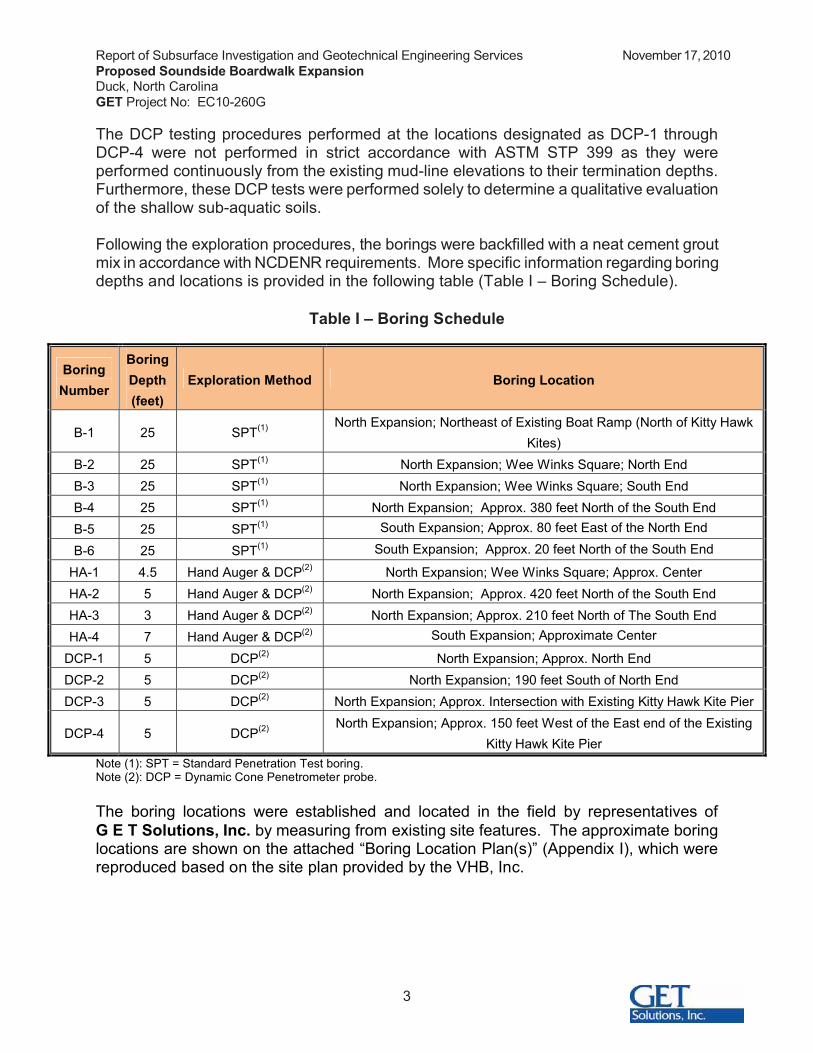
Following the exploration procedures, the borings were backfilled with a neat cement grout mix in accordance with NCDENR requirements. More specific information regarding boring depths and locations is provided in the following table (Table I – Boring Schedule).
Table I – Boring Schedule
BoringNumber
BoringDepth(feet)
Exploration Method Boring Location
B-1 25 SPT(1) North Expansion; Northeast of Existing Boat Ramp (North of Kitty Hawk Kites)
B-2 25 SPT(1) North Expansion; Wee Winks Square; North EndB-3 25 SPT(1) North Expansion; Wee Winks Square; South EndB-4 25 SPT(1) North Expansion; Approx. 380 feet North of the South End B-5 25 SPT(1) South Expansion; Approx. 80 feet East of the North End
B-6 25 SPT(1) South Expansion; Approx. 20 feet North of the South End
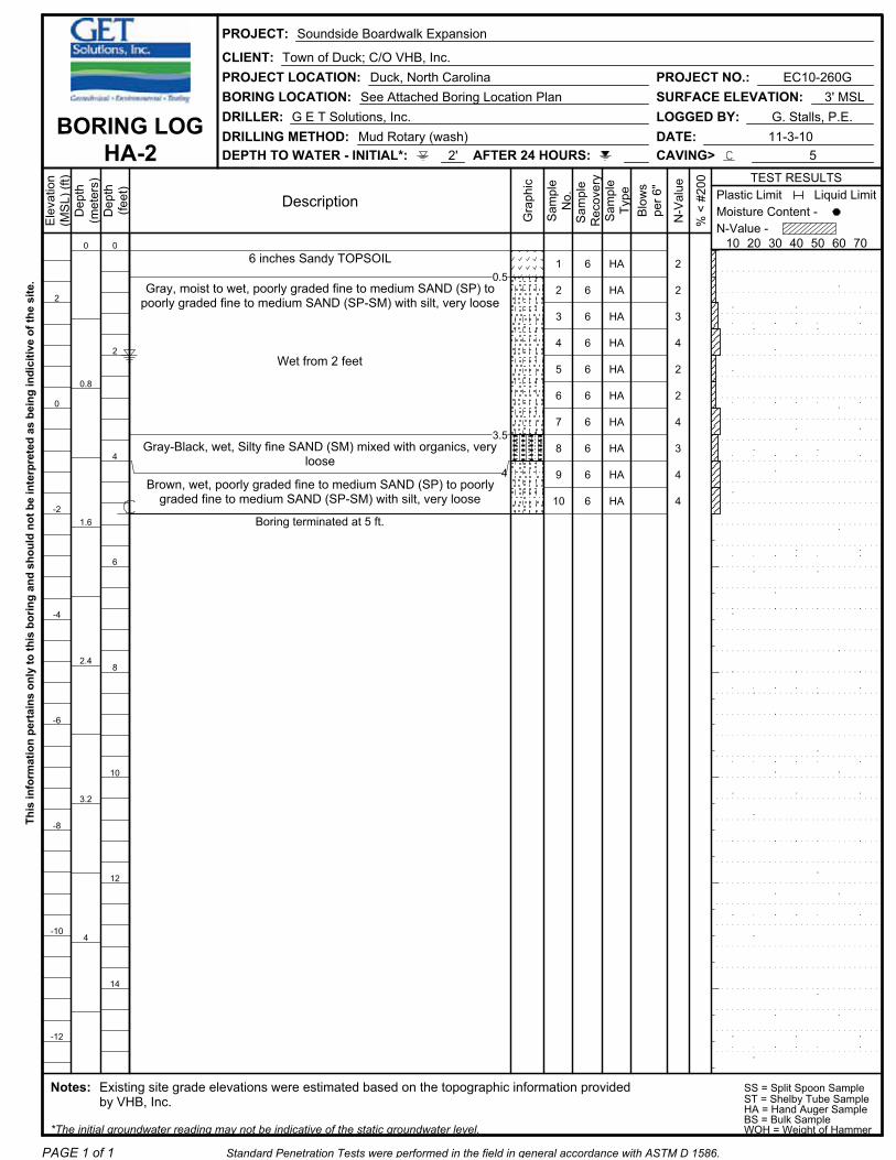
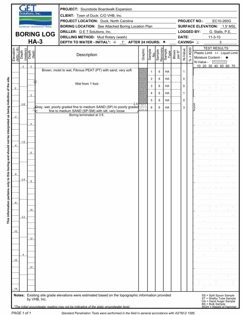
HA-1 4.5 Hand Auger & DCP(2) North Expansion; Wee Winks Square; Approx. CenterHA-2 5 Hand Auger & DCP(2) North Expansion; Approx. 420 feet North of the South End HA-3 3 Hand Auger & DCP(2) North Expansion; Approx. 210 feet North of The South End HA-4 7 Hand Auger & DCP(2) South Expansion; Approximate Center
DCP-1 5 DCP(2) North Expansion; Approx. North EndDCP-2 5 DCP(2) North Expansion; 190 feet South of North EndDCP-3 5 DCP(2) North Expansion; Approx. Intersection with Existing Kitty Hawk Kite Pier
DCP-4 5 DCP(2) North Expansion; Approx. 150 feet West of the East end of the Existing Kitty Hawk Kite Pier
Note (1): SPT = Standard Penetration Test boring.Note (2): DCP = Dynamic Cone Penetrometer probe.
The boring locations were established and located in the field by representatives of G E T Solutions, Inc. by measuring from existing site features. The approximate boring locations are shown on the attached “Boring Location Plan(s)” (Appendix I), which werereproduced based on the site plan provided by the VHB, Inc.
Report of Subsurface Investigation and Geotechnical Engineering Services November 17, 2010Proposed Soundside Boardwalk ExpansionDuck, North CarolinaGET Project No: EC10-260G
4
2.2 Laboratory Testing
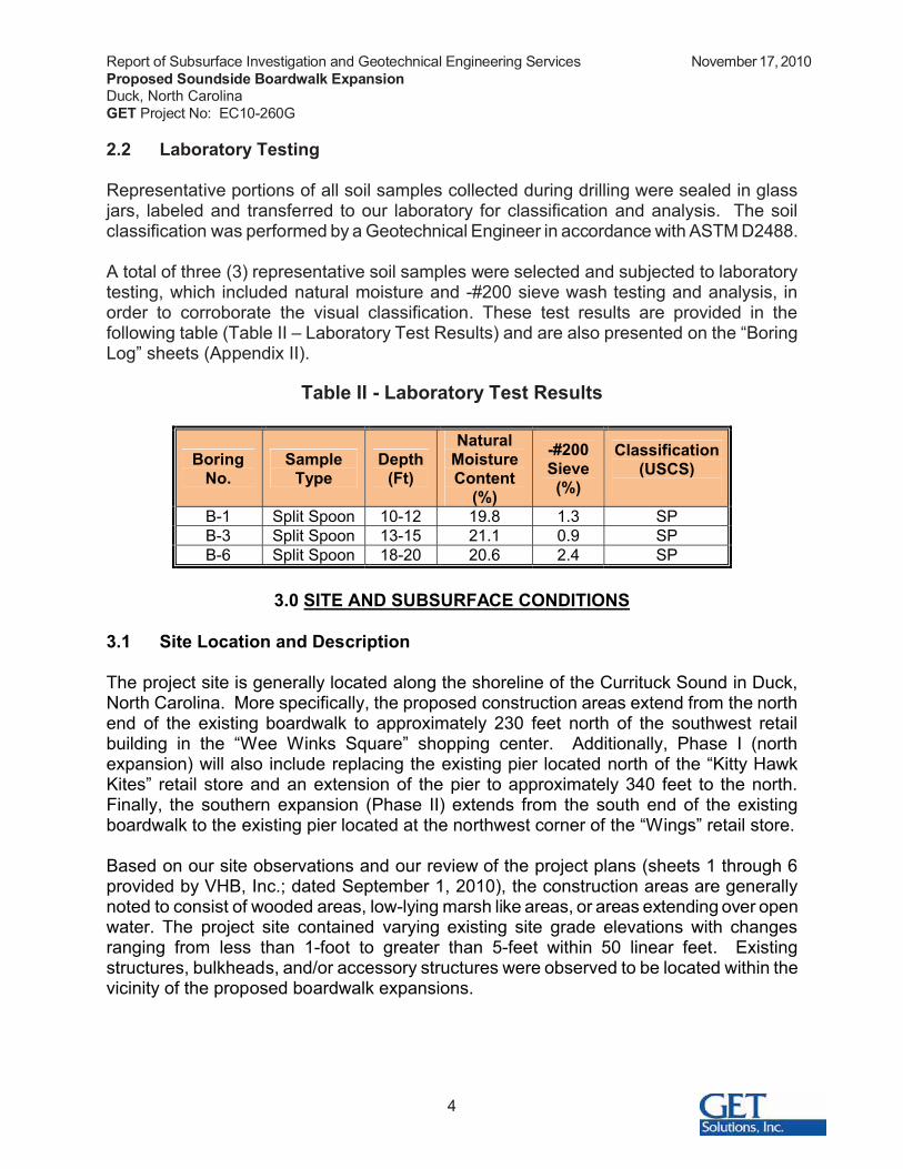
Representative portions of all soil samples collected during drilling were sealed in glass jars, labeled and transferred to our laboratory for classification and analysis. The soil classification was performed by a Geotechnical Engineer in accordance with ASTM D2488.
A total of three (3) representative soil samples were selected and subjected to laboratory testing, which included natural moisture and -#200 sieve wash testing and analysis, in order to corroborate the visual classification. These test results are provided in the following table (Table II – Laboratory Test Results) and are also presented on the “BoringLog” sheets (Appendix II).
Table II - Laboratory Test Results
BoringNo.
SampleType
Depth(Ft)
NaturalMoistureContent
(%)
-#200Sieve(%)
Classification(USCS)
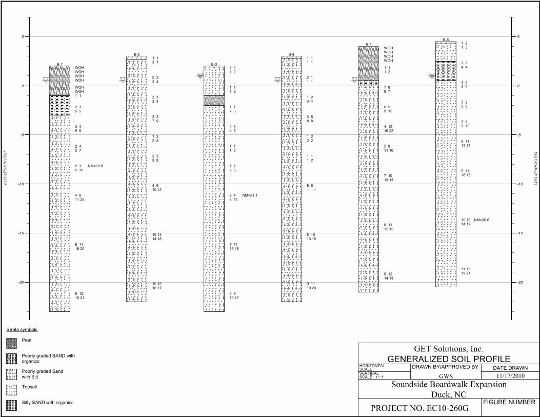
B-1 Split Spoon 10-12 19.8 1.3 SPB-3 Split Spoon 13-15 21.1 0.9 SPB-6 Split Spoon 18-20 20.6 2.4 SP
3.0 SITE AND SUBSURFACE CONDITIONS
3.1 Site Location and Description
The project site is generally located along the shoreline of the Currituck Sound in Duck, North Carolina. More specifically, the proposed construction areas extend from the north end of the existing boardwalk to approximately 230 feet north of the southwest retail building in the “Wee Winks Square” shopping center. Additionally, Phase I (north expansion) will also include replacing the existing pier located north of the “Kitty Hawk Kites” retail store and an extension of the pier to approximately 340 feet to the north. Finally, the southern expansion (Phase II) extends from the south end of the existing boardwalk to the existing pier located at the northwest corner of the “Wings” retail store.
Based on our site observations and our review of the project plans (sheets 1 through 6 provided by VHB, Inc.; dated September 1, 2010), the construction areas are generally noted to consist of wooded areas, low-lying marsh like areas, or areas extending over open water. The project site contained varying existing site grade elevations with changes ranging from less than 1-foot to greater than 5-feet within 50 linear feet. Existing structures, bulkheads, and/or accessory structures were observed to be located within the vicinity of the proposed boardwalk expansions.
Report of Subsurface Investigation and Geotechnical Engineering Services November 17, 2010Proposed Soundside Boardwalk ExpansionDuck, North CarolinaGET Project No: EC10-260G
5
3.2 Subsurface Soil Conditions
Borings B-1 through B-6 and HA-1 through HA-4:
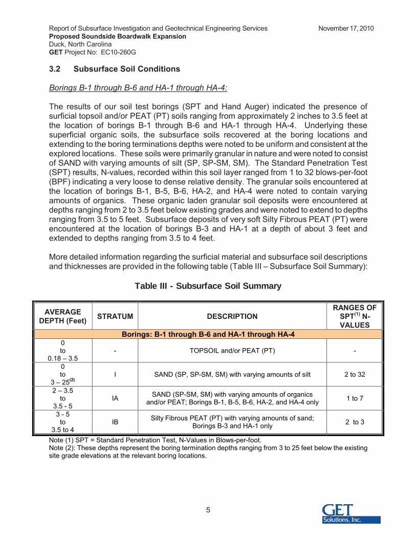
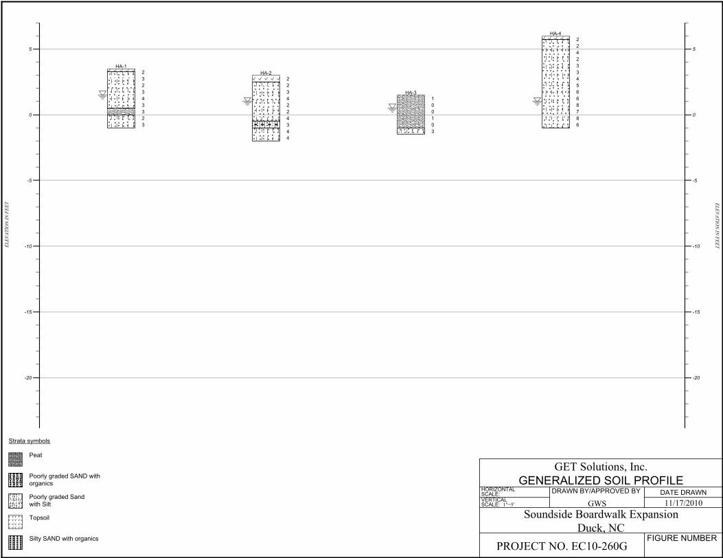
The results of our soil test borings (SPT and Hand Auger) indicated the presence of surficial topsoil and/or PEAT (PT) soils ranging from approximately 2 inches to 3.5 feet at the location of borings B-1 through B-6 and HA-1 through HA-4. Underlying these superficial organic soils, the subsurface soils recovered at the boring locations and extending to the boring terminations depths were noted to be uniform and consistent at the explored locations. These soils were primarily granular in nature and were noted to consist of SAND with varying amounts of silt (SP, SP-SM, SM). The Standard Penetration Test (SPT) results, N-values, recorded within this soil layer ranged from 1 to 32 blows-per-foot (BPF) indicating a very loose to dense relative density. The granular soils encountered at the location of borings B-1, B-5, B-6, HA-2, and HA-4 were noted to contain varying amounts of organics. These organic laden granular soil deposits were encountered at depths ranging from 2 to 3.5 feet below existing grades and were noted to extend to depths ranging from 3.5 to 5 feet. Subsurface deposits of very soft Silty Fibrous PEAT (PT) wereencountered at the location of borings B-3 and HA-1 at a depth of about 3 feet and extended to depths ranging from 3.5 to 4 feet.
More detailed information regarding the surficial material and subsurface soil descriptions and thicknesses are provided in the following table (Table III – Subsurface Soil Summary):
Table III - Subsurface Soil Summary
AVERAGE DEPTH (Feet) STRATUM DESCRIPTION
RANGES OFSPT(1) N-VALUES
Borings: B-1 through B-6 and HA-1 through HA-40to
0.18 – 3.5- TOPSOIL and/or PEAT (PT) -
0to
3 – 25(2)I SAND (SP, SP-SM, SM) with varying amounts of silt 2 to 32
2 – 3.5to
3.5 - 5IA SAND (SP-SM, SM) with varying amounts of organics
and/or PEAT; Borings B-1, B-5, B-6, HA-2, and HA-4 only 1 to 7
3 - 5to
3.5 to 4IB Silty Fibrous PEAT (PT) with varying amounts of sand;
Borings B-3 and HA-1 only 2 to 3
Note (1) SPT = Standard Penetration Test, N-Values in Blows-per-foot.Note (2): These depths represent the boring termination depths ranging from 3 to 25 feet below the existing site grade elevations at the relevant boring locations.
Report of Subsurface Investigation and Geotechnical Engineering Services November 17, 2010Proposed Soundside Boardwalk ExpansionDuck, North CarolinaGET Project No: EC10-260G
6
The subsurface description is of a generalized nature provided to highlight the major soil strata encountered. The records of the subsurface exploration are included in Appendix II (Boring Log sheets) and in Appendix III (Generalized Soil Profile), which should be reviewed for specific information as to the individual borings. The stratifications shown on the records of the subsurface exploration represent the conditions only at the actual boring locations. Variations may occur and should be expected between boring locations. The stratifications represent the approximate boundary between subsurface materials and the transition may be gradual.
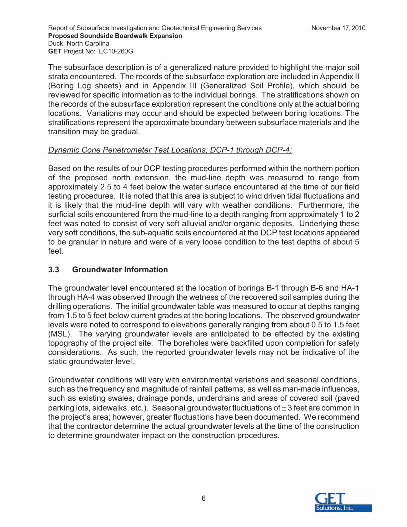
Dynamic Cone Penetrometer Test Locations; DCP-1 through DCP-4:
Based on the results of our DCP testing procedures performed within the northern portion of the proposed north extension, the mud-line depth was measured to range from approximately 2.5 to 4 feet below the water surface encountered at the time of our field testing procedures. It is noted that this area is subject to wind driven tidal fluctuations and it is likely that the mud-line depth will vary with weather conditions. Furthermore, the surficial soils encountered from the mud-line to a depth ranging from approximately 1 to 2 feet was noted to consist of very soft alluvial and/or organic deposits. Underlying these very soft conditions, the sub-aquatic soils encountered at the DCP test locations appeared to be granular in nature and were of a very loose condition to the test depths of about 5 feet.
3.3 Groundwater Information
The groundwater level encountered at the location of borings B-1 through B-6 and HA-1 through HA-4 was observed through the wetness of the recovered soil samples during the drilling operations. The initial groundwater table was measured to occur at depths ranging from 1.5 to 5 feet below current grades at the boring locations. The observed groundwater levels were noted to correspond to elevations generally ranging from about 0.5 to 1.5 feet (MSL). The varying groundwater levels are anticipated to be effected by the existing topography of the project site. The boreholes were backfilled upon completion for safety considerations. As such, the reported groundwater levels may not be indicative of the static groundwater level.
Groundwater conditions will vary with environmental variations and seasonal conditions, such as the frequency and magnitude of rainfall patterns, as well as man-made influences, such as existing swales, drainage ponds, underdrains and areas of covered soil (paved parking lots, sidewalks, etc.). Seasonal groundwater fluctuations of � 3 feet are common in the project’s area; however, greater fluctuations have been documented. We recommend that the contractor determine the actual groundwater levels at the time of the construction to determine groundwater impact on the construction procedures.

Report of Subsurface Investigation and Geotechnical Engineering Services November 17, 2010Proposed Soundside Boardwalk ExpansionDuck, North CarolinaGET Project No: EC10-260G
7
4.0 EVALUATIONS AND RECOMMENDATIONS
Our recommendations are based on the previously discussed project information, our interpretation of the soil test borings and laboratory data, and our observations during our site reconnaissance. If the proposed construction should vary from what was described, we request the opportunity to review our recommendations and make any necessary changes.
4.1 Boardwalk Foundation Design Recommendations:
Based on a review of the soil test borings, the proposed boardwalk can be supported by a deep foundation system comprised of round timber piles. We conducted static capacity analyses on the timber piles using equations for shaft friction and/or end bearing that incorporated our experience and that of published information on displacement piles. It is noted that the existing subsurface organic soils, where encountered, will contribute towards the applied pile loads as a result of compression of the soils and associated negative skin friction. Our individual pile axial capacity estimates, which include the adverse affects of negative skin friction, versus pile embedment lengths are tabulated below:
Pile Type and Dimensions
PileEmbedment
Depth(feet)(1)
Pile Tip Elevations(2)
Allowable Capacity in
Compression(tons)(3)
Allowable Capacity in
Tension(tons)
Allowable Lateral
Capacity(tons)(4)
Borings B-1, B-5, and B-6Round Timber
(8-inchminimum tip
diameter)
15 -10 to -12 15 3.0 0.5
Borings B-2, B-3, and B-4Round Timber
(8-inchminimum tip
diameter)
20 -15 to -17 15 4.0 0.5
Note (1): Pile embedment depths are referenced from beneath the existing site grade elevations at the time of our subsurface exploration for each boring location.
Note (2): Pile tip elevations are referenced from Mean Sea Level (MSL), are based on the topographic information provided by VHB, Inc., and are considered to be approximate.
Note (3): Piles should be installed and tested to ultimate capacities (2.25 times the allowable capacities) to account for negative skin friction loads.
Note (4): Lateral capacity computed for a lateral load applied at free pile butt level, at ground level for a maximum butt deflection of ½ inch. Batter piles would enhance stability.
In order to effectively provide allowable lateral capacities, pile butt elevations and brace design (free or fixed pile butt) is required. The previously shown pile embedment depth is required to achieve the allowable capacities. Any reduction in the length of embedment will correspond to a reduction in the allowable design capacity, unless otherwise directed by the geotechnical engineer after the pile-testing program.

Report of Subsurface Investigation and Geotechnical Engineering Services November 17, 2010Proposed Soundside Boardwalk ExpansionDuck, North CarolinaGET Project No: EC10-260G
8
In order to minimize the reduction in capacity due to group action of the piles, it is recommended that the piles be installed with a center-to-center spacing of at least 3 feet. If for some reason during construction, pile “refusal” is encountered before piles reach their design tip elevation, the Geotechnical Engineer should be retained to review field records and reports before assuming the pile can adequately support the design capacity.
4.2 Pile Settlements – Preliminary:
Based on the results of load tests performed on piles installed in similar soils conditions, it is anticipated that the total settlements will be less than approximately 1 inch.
4.3 Timber Piles:
In accordance with the above discussion, it is anticipated that driven round treated timber piles will be selected to support the building frame and first floor of the structures.
It is recommended that the timber piles meet the requirements of ASTM D-25 for timber tip bearing piles. The piles should be clean peeled and pressure treated in accordance with the requirements of AWPA C3. The timber pile design stresses should be established in accordance with ASTM D-2899 and the local applicable Building Codes. Additionally, we recommend the timber piles be treated with ACA (ammoniated copper arsenate) and CCA (copper chrome arsenate) due to the location of the proposed structure in a temperature zone coastal environment. Prior to driving, it is recommended that timber piles be relatively free of defects and have a water content greater than approximately 20 percent (to minimize “breaking”) and less than about 50 percent (to minimize “brooming”).
Driven timber piles will derive their long-term capacity from shaft friction and end bearing support via embedment within the predominately clayey soils encountered at this site. These soil materials typically exhibit time-dependent strength characteristics, consequently shaft friction and end bearing support tend to increase from initial installation through a process termed “soil setup”. Essentially, the dynamics of driving piles through these sandy materials will cause excess pore pressures to develop, thereby decreasing driving resistance during initial pile installation. The pile capacities developed during driving are usually much lower than the design values. However, once driving is complete, these pore pressures dissipate with time (and soil setup occurs) and the bearing capacity of the pile increases. Based upon our experience with similar projects in the area, 24 to 72 hours is usually required for the pore pressures to dissipate.
For the reasons described previously, it may not be possible to confirm pile capacities with a simple driving criteria such as number of hammer blows per foot of advanced pile. Instead, driving criteria will likely consist of a target tip elevation and/or certain embedded length in a bearing material with specified driving resistance. In order to confirm the required tip elevations, we recommend conducting a Test Pile Program prior to ordering production piles, as will be discussed later in this report.

Report of Subsurface Investigation and Geotechnical Engineering Services November 17, 2010Proposed Soundside Boardwalk ExpansionDuck, North CarolinaGET Project No: EC10-260G
9
4.4 Pile Installation Monitoring – Pre-Augered or Jetted Piles:
In order to develop the allowable pile capacities provided in Section 4.1 of this report and in the event that pre-augering and/or jetting is implemented, it is considered necessary to install the timber piles by means of pre-auguring to a maximum depth of about 3 feet below the existing site grade elevations to initially “set” the piles. Subsequently, the piles should be jetted to a depth of approximately 4 to 5 feet above the proposed pile tip elevation. Following the pre-auger and/or jetting procedures, the piles should be driven to the pile tip elevation under the observation of the G E T Solutions, Inc. representative. The purpose of the inspector’s observations is to determine if test and production pile installations are being performed in accordance with acceptable methods. Continuous installation records should be maintained for all piles.
A qualified inspector should observe the installation of the piles. The purpose of the inspector’s observations is to determine if production installations are being performed in accordance with acceptable methods. Continuous installation records should be maintained for all piles.
The field duties of the inspector should include the following:
� Being knowledgeable of the subsurface conditions at the site and the project-specific Pile Installation Criteria.
� Being aware of aspects of the installation including type of equipment and pile installation tolerances.
� Keeping an accurate record of pile installation procedures.� Documenting that the piles are installed to the proper depth indicative of the
intended bearing stratum. � Recording the number of hammer blows for each foot of driving (during all
installation procedures).� Generally confirming that the pile installation equipment is operating as
anticipated.� Record the energy rating of the hammer (for all installation procedures).� Informing the Geotechnical Engineer of any unusual subsurface conditions
or driving conditions.� Notifying the contractor and structural engineer when unanticipated
difficulties or conditions are encountered.� Confirming from visual appearance that the piles are not damaged during
installation and observing the piles prior to installation for defective workmanship. The geotechnical engineer should review all installation records prior to initiating the following phase of construction.
Report of Subsurface Investigation and Geotechnical Engineering Services November 17, 2010Proposed Soundside Boardwalk ExpansionDuck, North CarolinaGET Project No: EC10-260G
10
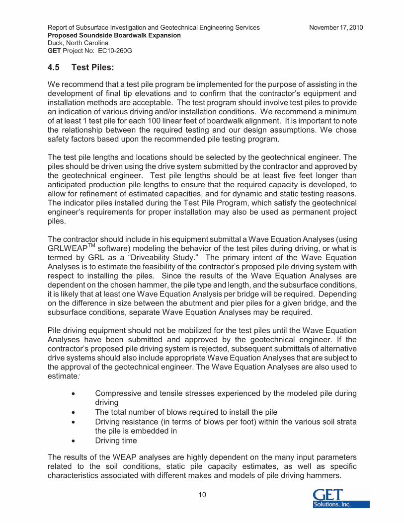
4.5 Test Piles:
We recommend that a test pile program be implemented for the purpose of assisting in the development of final tip elevations and to confirm that the contractor’s equipment and installation methods are acceptable. The test program should involve test piles to provide an indication of various driving and/or installation conditions. We recommend a minimumof at least 1 test pile for each 100 linear feet of boardwalk alignment. It is important to note the relationship between the required testing and our design assumptions. We chose safety factors based upon the recommended pile testing program.
The test pile lengths and locations should be selected by the geotechnical engineer. The piles should be driven using the drive system submitted by the contractor and approved by the geotechnical engineer. Test pile lengths should be at least five feet longer than anticipated production pile lengths to ensure that the required capacity is developed, to allow for refinement of estimated capacities, and for dynamic and static testing reasons. The indicator piles installed during the Test Pile Program, which satisfy the geotechnical engineer’s requirements for proper installation may also be used as permanent project piles.
The contractor should include in his equipment submittal a Wave Equation Analyses (using GRLWEAPTM software) modeling the behavior of the test piles during driving, or what is termed by GRL as a “Driveability Study.” The primary intent of the Wave Equation Analyses is to estimate the feasibility of the contractor’s proposed pile driving system with respect to installing the piles. Since the results of the Wave Equation Analyses are dependent on the chosen hammer, the pile type and length, and the subsurface conditions, it is likely that at least one Wave Equation Analysis per bridge will be required. Depending on the difference in size between the abutment and pier piles for a given bridge, and the subsurface conditions, separate Wave Equation Analyses may be required.
Pile driving equipment should not be mobilized for the test piles until the Wave Equation Analyses have been submitted and approved by the geotechnical engineer. If the contractor’s proposed pile driving system is rejected, subsequent submittals of alternative drive systems should also include appropriate Wave Equation Analyses that are subject to the approval of the geotechnical engineer. The Wave Equation Analyses are also used to estimate:
� Compressive and tensile stresses experienced by the modeled pile during driving
� The total number of blows required to install the pile� Driving resistance (in terms of blows per foot) within the various soil strata
the pile is embedded in� Driving time
The results of the WEAP analyses are highly dependent on the many input parameters related to the soil conditions, static pile capacity estimates, as well as specific characteristics associated with different makes and models of pile driving hammers.

Report of Subsurface Investigation and Geotechnical Engineering Services November 17, 2010Proposed Soundside Boardwalk ExpansionDuck, North CarolinaGET Project No: EC10-260G
11
4.6 Establishing Pile Driving Criteria – Driven Piles:
Prior to driving production piles, the geotechnical engineer should establish the criteria for pile installation. The criteria will be based on the test data collected during monitoring of the initial drive of the test piles and the subsequent re-strikes. The intent of establishing driving criteria is to facilitate installation of the production piles without damage and to provide a means of establishing when piles have achieved the design capacities. The driving criteria may include: hammer type, hammer energy, ram weight, pile cushion and thickness, hammer cushion type and thickness, required tip elevations and driving resistance necessary to achieve capacities, and possibly pre-drilling/jetting recommendations (if the test pile results warrant the need).
4.7 Pile Installation Monitoring:
The geotechnical engineer should observe the installation of the test piles and all production piles. The purpose of the geotechnical engineer’s observations is to determine if production installations are being performed in accordance with the previously derived Pile Driving Criteria. Continuous driving and installation records should be maintained for all driven piles. Production piles should be driven utilizing the approved system established as a result of the Test Program. The field duties of the geotechnical engineer (or a qualified engineer’s representative) should include the following:
1. Being knowledgeable of the subsurface conditions at the site and the project-specific Pile Driving Criteria.
2. Being aware of aspects of the installation including type of pile driving equipment and pile installation tolerances.
3. Keeping an accurate record of pile installation and driving procedures.
4. Documenting that the piles are installed to the proper depth indicative of the intended bearing stratum. Also documenting that appropriate pile splicing techniques are used, if necessary.
5. Recording the number of hammer blows for each foot of driving.
6. Generally confirming that the pile driving equipment is operating as anticipated. Record the energy rating of the hammer.
7. Informing the geotechnical engineer of any unusual subsurface conditions or driving conditions.
8. Notifying the contractor and structural engineer when unanticipated difficulties or conditions are encountered.
9. Confirming from visual appearance that the piles are not damaged during installation and observing the piles prior to installation for defective workmanship. The geotechnical engineer should review all driving records prior to pile cap construction.
Report of Subsurface Investigation and Geotechnical Engineering Services November 17, 2010Proposed Soundside Boardwalk ExpansionDuck, North CarolinaGET Project No: EC10-260G
12
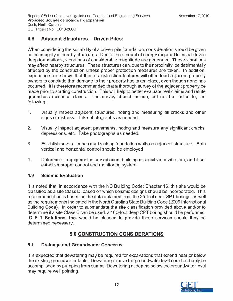
4.8 Adjacent Structures – Driven Piles:
When considering the suitability of a driven pile foundation, consideration should be given to the integrity of nearby structures. Due to the amount of energy required to install driven deep foundations, vibrations of considerable magnitude are generated. These vibrations may affect nearby structures. These structures can, due to their proximity, be detrimentally affected by the construction unless proper protection measures are taken. In addition, experience has shown that these construction features will often lead adjacent property owners to conclude that damage to their property has taken place, even though none has occurred. It is therefore recommended that a thorough survey of the adjacent property be made prior to starting construction. This will help to better evaluate real claims and refute groundless nuisance claims. The survey should include, but not be limited to, the following:
1. Visually inspect adjacent structures, noting and measuring all cracks and other signs of distress. Take photographs as needed.
2. Visually inspect adjacent pavements, noting and measure any significant cracks, depressions, etc. Take photographs as needed.
3. Establish several bench marks along foundation walls on adjacent structures. Both vertical and horizontal control should be employed.
4. Determine if equipment in any adjacent building is sensitive to vibration, and if so, establish proper control and monitoring system.
4.9 Seismic Evaluation
It is noted that, in accordance with the NC Building Code; Chapter 16, this site would be classified as a site Class D, based on which seismic designs should be incorporated. This recommendation is based on the data obtained from the 25-foot deep SPT borings, as well as the requirements indicated in the North Carolina State Building Code (2009 International Building Code). In order to substantiate the site classification provided above and/or to determine if a site Class C can be used, a 100-foot deep CPT boring should be performed. G E T Solutions, Inc. would be pleased to provide these services should they be
determined necessary.
5.0 CONSTRUCTION CONSIDERATIONS
5.1 Drainage and Groundwater Concerns
It is expected that dewatering may be required for excavations that extend near or below the existing groundwater table. Dewatering above the groundwater level could probably be accomplished by pumping from sumps. Dewatering at depths below the groundwater level may require well pointing.
Report of Subsurface Investigation and Geotechnical Engineering Services November 17, 2010Proposed Soundside Boardwalk ExpansionDuck, North CarolinaGET Project No: EC10-260G
13
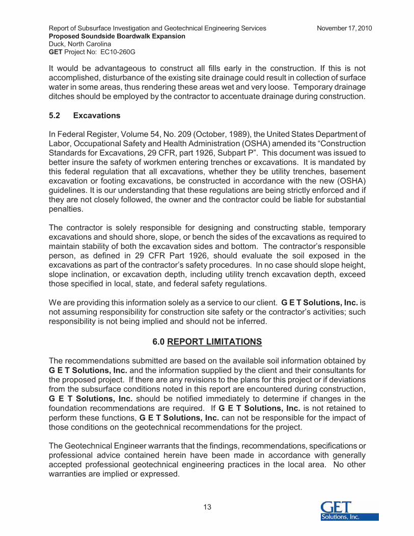
It would be advantageous to construct all fills early in the construction. If this is not accomplished, disturbance of the existing site drainage could result in collection of surface water in some areas, thus rendering these areas wet and very loose. Temporary drainage ditches should be employed by the contractor to accentuate drainage during construction.
5.2 Excavations
In Federal Register, Volume 54, No. 209 (October, 1989), the United States Department of Labor, Occupational Safety and Health Administration (OSHA) amended its “Construction Standards for Excavations, 29 CFR, part 1926, Subpart P”. This document was issued to better insure the safety of workmen entering trenches or excavations. It is mandated by this federal regulation that all excavations, whether they be utility trenches, basement excavation or footing excavations, be constructed in accordance with the new (OSHA) guidelines. It is our understanding that these regulations are being strictly enforced and if they are not closely followed, the owner and the contractor could be liable for substantial penalties.
The contractor is solely responsible for designing and constructing stable, temporary excavations and should shore, slope, or bench the sides of the excavations as required to maintain stability of both the excavation sides and bottom. The contractor’s responsible person, as defined in 29 CFR Part 1926, should evaluate the soil exposed in the excavations as part of the contractor’s safety procedures. In no case should slope height, slope inclination, or excavation depth, including utility trench excavation depth, exceed those specified in local, state, and federal safety regulations.
We are providing this information solely as a service to our client. G E T Solutions, Inc. is not assuming responsibility for construction site safety or the contractor’s activities; such responsibility is not being implied and should not be inferred.
6.0 REPORT LIMITATIONS
The recommendations submitted are based on the available soil information obtained by G E T Solutions, Inc. and the information supplied by the client and their consultants for the proposed project. If there are any revisions to the plans for this project or if deviations from the subsurface conditions noted in this report are encountered during construction, G E T Solutions, Inc. should be notified immediately to determine if changes in the foundation recommendations are required. If G E T Solutions, Inc. is not retained to perform these functions, G E T Solutions, Inc. can not be responsible for the impact of those conditions on the geotechnical recommendations for the project.
The Geotechnical Engineer warrants that the findings, recommendations, specifications or professional advice contained herein have been made in accordance with generally accepted professional geotechnical engineering practices in the local area. No other warranties are implied or expressed.
Report of Subsurface Investigation and Geotechnical Engineering Services November 17, 2010Proposed Soundside Boardwalk ExpansionDuck, North CarolinaGET Project No: EC10-260G
14
After the plans and specifications are more complete the Geotechnical Engineer should be provided the opportunity to review the final design plans and specifications to assure our engineering recommendations have been properly incorporated into the design documents, in order that the earthwork and foundation recommendations may be properly interpreted and implemented. At that time, it may be necessary to submit supplementary recommendations. This report has been prepared for the exclusive use of the Town of Duck, VHB, Inc., and their consultants for the specific application to the proposed Soundside Boardwalk Expansions located in Duck, North Carolina.
APPENDICES
I BORING LOCATION PLAN
II BORING LOGS
III GENERALIZED SOIL PROFILE
IV CLASSIFICATION SYSTEM FOR SOIL EXPLORAITON

APPENDIX I
BORING LOCATION PLAN

APPENDIX II
BORING LOGS
�
��
���
���
���
���
���
���
�
�
�
��
�
�
��
��
��
��
��
��
�� ����� ����� ���������������� ������ �!� "��#����� $�
%���$� ���&��$���
�' ����(�)�*���� ���������+ ����,�*(�(�$����� ���(������-.�!���
�'"����/������*�(� �,*��0���#����� ���
)�*��������+ ����,�*(�(�$����� ���(������-.�!��"�� �+ ����,�*(�($����� ���(������-.�!����'"����/�������� ���� ���(����(����
%��/�'*������/������*,������$� ����� ����$���
� ���,�������*��(�*�����$�&
�
�
�
�
�
1
2
��
�
��
��
��
��
��
��
��
��
��
��
��
��
��
��
��
��
%34%34%34%34%34%34������������1�����
�����
������
�����
�
�
2
2
�2
�
�
�&�
������� � ��(��(��� *�(�*�5��6+*��� �
����� ��� $�.�057�893�:4���;�0&������� ������� .�05��- ��/�8*� ���* ������� ��� �8�����)������ ������� �������*0/�(�� ���,�< 0*�� ����*� ������� �������� �=�'�<
������ �����
����� )��� �� ���� ����;�0& ����� �� )&���*������&�&������ ������ '�(�> �*���!�*�/" ���� ������������ �� ����� � ������� �&�= ����� �� ����� ������
�!"#$ �6�����,������,�*(�����#*�� �������������*��(��*��(� ���/��� + ,�*+/�0���$ ��*�� ��+� #�(�(���:4���;�0&
���?��+�����+ ���*�+��� �?��/����� �����*�+��4��?�4*�(���,����*�+�����?����5��*�+��
������������ ������ � ����������������������������������� ������ ������� %34�?�%��,/�� $�4*����
���#*�� �
!'�<"�!$�"
.�+�/
!������"
.�+�/
!$���"
.��0��+�� �
)�*+/�0
�*�
+��
- &
�*�
+���
>�0 #���
�*�
+��
�+�
�� ��
+���@
-�:*���
A�B�C��� �� �>��D< �
�� �� �� �� �� � 1�-�:*�����' �������8 ���������*���0�<���� <�E��(�<����
�%&$ &'(!)*
+"&!' ,#)"+&'$ !'-. "! "%
&$ /!)&'0 +'1 $%!2
-1 '!" /# &'"#),)#"#1 +$ /#&'0
&'1&3&"&4# !( "%
# $&"#�
��� ������ ����������� ���� �� ����������������������� ����� ���������������� !"#���$%� ����
�
��
���
���
���
���
���
���
�
�
�
��
�
�
��
��
��
��
��
��
����0/����*�(�� 3��3;<�&�
*���� ����� ������+ ����,�*(�(�$����� ���(������-.�!��"�� �+ ���,�*(�(�$����� ���(������-.�!����'"����/�������#����� ���� �(����
)�*��$� ����$���%���$� ���&��$���
%��/�'*������/������*,������$� ����� ����$���
� ���,�������*��(�*�����$�&
�
�
�
�
�
1
2
�
�2
��
��
��
��
��
��
��
��
��
��
��
��
��
��
��
��
��������������12�������
�����
�������
�����1
�
�
��
�
�
�
��
������� � ��(��(��� *�(�*�5��6+*��� �
����� ��� $�.�057�893�:4���;�0&������� ������� .�05��- ��/�8*� ���* ������� ��� �8�����)������ ������� �������*0/�(�� ���,�< 0*�� ����*� ������� �������� �=�'�<
������ �����
����� )��� �� ���� ����;�0& ����� �� )&���*������&�&������ ������ '�(�> �*���!�*�/" ���� ������������ �� ����� � ������� �&�= ����� �� ����� ������
�!"#$ �6�����,������,�*(�����#*�� �������������*��(��*��(� ���/��� + ,�*+/�0���$ ��*�� ��+� #�(�(���:4���;�0&
���?��+�����+ ���*�+��� �?��/����� �����*�+��4��?�4*�(���,����*�+�����?����5��*�+��
������������ ������ � ����������������������������������� ������ ������� %34�?�%��,/�� $�4*����
���#*�� �
!'�<"�!$�"
.�+�/
!������"
.�+�/
!$���"
.��0��+�� �
)�*+/�0
�*�
+��
- &
�*�
+���
>�0 #���
�*�
+��
�+�
�� ��
+���@
-�:*���
A�B�C��� �� �>��D< �
�� �� �� �� �� � 1�-�:*�����' �������8 ���������*���0�<���� <�E��(�<����
�%&$ &'(!)*
+"&!' ,#)"+&'$ !'-. "! "%
&$ /!)&'0 +'1 $%!2
-1 '!" /# &'"#),)#"#1 +$ /#&'0
&'1&3&"&4# !( "%
# $&"#�
��� ������ ����������� ���� �� ����������������������� ����� ���������������� !"#���$%� ����
�
��
���
���
���
���
���
���
�
�
�
��
�
�
��
��
��
��
��
��
����0/����*�(�� 3��3;<�&�
)�*���� ����� ������+ ����,�*(�(�$����� ���(������-.�!��"�� + ����,�*(�(�$����� ���(������-.�!����'"����/�������#����� ��
%���$� ����$ ��
��*05����������������� ������ �!� "��#����� $��
�� ���������+ ����,�*(�(�$����� ���(������-.�!��"�� �+ ���,�*(�(�$����� ���(������-.�!����'"����/�������#����� ����
��(����(����)�*��$� ���$���
� ���,�������*��(�*�����$�&
�
�
�
�
�
1
2
��
��
��
��
�2
�2
�
��
��
��
��
��
��
��
��
��
��
��
������������������������
����
1����
���1
�
�
�
1
�
�
��
�1
�
�&2
������� � ��(��(��� *�(�*�5��6+*��� �
����� ��� $�.�057�893�:4���;�0&������� ������� .�05��- ��/�8*� ���* ������� ��� �8�����)������ ������� �������*0/�(�� ���,�< 0*�� ����*� ������� �������� �=�'�<
������ ����5
����� )��� �� ���� ����;�0& ����� �� )&���*������&�&������ ������ '�(�> �*���!�*�/" ���� ������������ �� ����� � ������� �= ����� �� ����� ������
�!"#$ �6�����,������,�*(�����#*�� �������������*��(��*��(� ���/��� + ,�*+/�0���$ ��*�� ��+� #�(�(���:4���;�0&
���?��+�����+ ���*�+��� �?��/����� �����*�+��4��?�4*�(���,����*�+�����?����5��*�+��
������������ ������ � ����������������������������������� ������ ������� %34�?�%��,/�� $�4*����
���#*�� �
!'�<"�!$�"
.�+�/
!������"
.�+�/
!$���"
.��0��+�� �
)�*+/�0
�*�
+��
- &
�*�
+���
>�0 #���
�*�
+��
�+�
�� ��
+���@
-�:*���
A�B�C��� �� �>��D< �
�� �� �� �� �� � 1�-�:*�����' �������8 ���������*���0�<���� <�E��(�<����
�%&$ &'(!)*
+"&!' ,#)"+&'$ !'-. "! "%
&$ /!)&'0 +'1 $%!2
-1 '!" /# &'"#),)#"#1 +$ /#&'0
&'1&3&"&4# !( "%
# $&"#�
��� ������ ����������� ���� �� ����������������������� ����� ���������������� !"#���$%� ����
�
��
���
���
���
���
���
���
�
�
�
��
�
�
��
��
��
��
��
��
����0/����*�(�� 3��3;<�&�
*���� ����� ������+ ����,�*(�(�$����� ���(������-.�!��"�� �+ ���,�*(�(�$����� ���(������-.�!����'"����/�������#����� ����
��(����(����%���$� ���&��$ �
*��)�*��$� ����$���
)�*��$� �����$���
� ���,�������*��(�*�����$�&
�
�
�
�
�
1
2
�
��
��
��
�
�
��
��
��
��
��
��
��
��
��
��
��
��
����������������������
�����
�������
2���2��
�
�
�
��
�
�
�1
��
��
������� � ��(��(��� *�(�*�5��6+*��� �
����� ��� $�.�057�893�:4���;�0&������� ������� .�05��- ��/�8*� ���* ������� ��� �8�����)������ ������� �������*0/�(�� ���,�< 0*�� ����*� ������� �������� �=�'�<
������ �����
����� )��� �� ���� ����;�0& ����� �� )&���*������&�&������ ������ '�(�> �*���!�*�/" ���� ����������� �� ����� � ������� �&�= ����� �� ����� ������
�!"#$ �6�����,������,�*(�����#*�� �������������*��(��*��(� ���/��� + ,�*+/�0���$ ��*�� ��+� #�(�(���:4���;�0&
���?��+�����+ ���*�+��� �?��/����� �����*�+��4��?�4*�(���,����*�+�����?����5��*�+��
������������ ������ � ����������������������������������� ������ ������� %34�?�%��,/�� $�4*����
���#*�� �
!'�<"�!$�"
.�+�/
!������"
.�+�/
!$���"
.��0��+�� �
)�*+/�0
�*�
+��
- &
�*�
+���
>�0 #���
�*�
+��
�+�
�� ��
+���@
-�:*���
A�B�C��� �� �>��D< �
�� �� �� �� �� � 1�-�:*�����' �������8 ���������*���0�<���� <�E��(�<����
�%&$ &'(!)*
+"&!' ,#)"+&'$ !'-. "! "%
&$ /!)&'0 +'1 $%!2
-1 '!" /# &'"#),)#"#1 +$ /#&'0
&'1&3&"&4# !( "%
# $&"#�
��� ������ ����������� ���� �� ����������������������� ����� ���������������� !"#���$%� ����
�
��
���
���
���
���
���
�
�
�
��
�
�
��
��
��
��
��
��
��*05��� ����� �#����� ��������������� ������ �!� "��#����� $�
�&�)�*��������������$������-.�!�'"���6�(����/� �,*��0���#����� ��
�)�*��������+ ����,�*(�(�$����� ���(������-.�!��"�� �+ ����,�*(�(
$����� ���(������-.�!����'"����/���������(����(����
� ���,�������*��(�*�����$�&
�
�
�
�
�
1
2
��
�
��
��
��
��
��
��
��
��
��
��
��
��
��
��
��
��
%34%34%34%34����1122���������2����
1������
������
2������
�
�
�
�
�
��
��
��
�
������� � ��(��(��� *�(�*�5��6+*��� �
����� ��� $�.�057�893�:4���;�0&������� ������� .�05��- ��/�8*� ���* ������� ��� �8�����)������ ������� �������*0/�(�� ���,�< 0*�� ����*� ������� �������� �=�'�<
������ ����6
����� )��� �� ���� ����;�0& ����� �� )&���*������&�&������ ������ '�(�> �*���!�*�/" ���� ���2�������� �� ����� � ������� �&�= ����� �� ����� ������
�!"#$ �6�����,������,�*(�����#*�� �������������*��(��*��(� ���/��� + ,�*+/�0���$ ��*�� ��+� #�(�(���:4���;�0&
���?��+�����+ ���*�+��� �?��/����� �����*�+��4��?�4*�(���,����*�+�����?����5��*�+��
������������ ������ � ����������������������������������� ������ ������� %34�?�%��,/�� $�4*����
���#*�� �
!'�<"�!$�"
.�+�/
!������"
.�+�/
!$���"
.��0��+�� �
)�*+/�0
�*�
+��
- &
�*�
+���
>�0 #���
�*�
+��
�+�
�� ��
+���@
-�:*���
A�B�C��� �� �>��D< �
�� �� �� �� �� � 1�-�:*�����' �������8 ���������*���0�<���� <�E��(�<����
�%&$ &'(!)*
+"&!' ,#)"+&'$ !'-. "! "%
&$ /!)&'0 +'1 $%!2
-1 '!" /# &'"#),)#"#1 +$ /#&'0
&'1&3&"&4# !( "%
# $&"#�
��� ������ ����������� ���� �� ����������������������� ����� ���������������� !"#���$%� ����
�
��
���
���
���
���
���
�
�
�
��
�
�
��
��
��
��
��
��
����0/����*�(�� 3��3;<�&��
*���� ����� �#����� �����+ ����,�*(�(�$����� ���(������-.�!����'"����/�������#����� ��
� *���� ����� ������+ ����,�*(�(�$����� ���(������-.�!����'"
��6�(����/� �,*��0���� ��%���$� ���&��$ �
�)�*��������+ ����,�*(�(�$����� ���(������-.�!��"�� �+ ����,�*(�($����� ���(������-.�!����'"����/�������� ���� ���(����(����
.*�5�)�*��*�(� �*0��3�,*��0��$� ���� ��$���
� ���,�������*��(�*�����$�&
�
�
�
�
�
1
2
��
��
�
��
��
��
��
��
��
��
��
��
��
��
��
��
��
��
����������������2��������
2����
�������1
�����2��
�
1
�
�1
��
�1
�2
��
�&�
������� � ��(��(��� *�(�*�5��6+*��� �
����� ��� $�.�057�893�:4���;�0&������� ������� .�05��- ��/�8*� ���* ������� ��� �8�����)������ ������� �������*0/�(�� ���,�< 0*�� ����*� ������� �������� �&�=�'�<
������ ����7
����� )��� �� ���� ����;�0& ����� �� )&���*������&�&������ ������ '�(�> �*���!�*�/" ���� ���2�������� �� ����� � ������� �&�= ����� �� ����� ������
�!"#$ �6�����,������,�*(�����#*�� �������������*��(��*��(� ���/��� + ,�*+/�0���$ ��*�� ��+� #�(�(���:4���;�0&
���?��+�����+ ���*�+��� �?��/����� �����*�+��4��?�4*�(���,����*�+�����?����5��*�+��
������������ ������ � ����������������������������������� ������ ������� %34�?�%��,/�� $�4*����
���#*�� �
!'�<"�!$�"
.�+�/
!������"
.�+�/
!$���"
.��0��+�� �
)�*+/�0
�*�
+��
- &
�*�
+���
>�0 #���
�*�
+��
�+�
�� ��
+���@
-�:*���
A�B�C��� �� �>��D< �
�� �� �� �� �� � 1�-�:*�����' �������8 ���������*���0�<���� <�E��(�<����
�%&$ &'(!)*
+"&!' ,#)"+&'$ !'-. "! "%
&$ /!)&'0 +'1 $%!2
-1 '!" /# &'"#),)#"#1 +$ /#&'0
&'1&3&"&4# !( "%
# $&"#�
��� ������ ����������� ���� �� ����������������������� ����� ���������������� !"#���$%� ����
��������� ��������������������������������������������������������������������������������� ������������������������������������������������������������!����������������� �"��#���������������������������������������������������$�������������������������������������������������������%���������������&��������������������'����������'��������������������������������(��)������������������������������������$�������������������������
���*
+ ��� ,��������+������ ����
-���
-� �������+. ,������������
-� �������+��������+���%����
+��� �+. ,������������
/�����+ ����0����������������������
8�� �� ������

�
�
��
��
�
�
���
���
�
�&
�&
�&�
�&�
�
�
�
�
��
��
��
����0/����*�(�� 3��3;<�&��
)�*���� ����� ������+ ����,�*(�(�$����� ���(������-.�!��"�� + ����,�*(�(�$����� ���(������-.�!����'"����/�������#����� ��
%���$� ����$���
%���$� ����$���
���*05����������������� ������ �!� "���6�(����/��*�(��#����� $�
�&��� ���������+ ����,�*(�(�$����� ���(������-.�!��"�� �+ ���,�*(�(�$����� ���(������-.�!����'"����/�������#����� ��
� ���,�������*��(�*���&��$�&
�
�
�
�
�
1
2
4�
4�
4�
4�
4�
4�
4�
4�
4�
�
�
�
�
�
�
�
�
�
������� � ��(��(��� *�(�*�5��6+*��� �
����� ��� $�.�057�893�:4���;�0&������� ������� .�05��- ��/�8*� ���* ������� ��� �8�����)������ ������� �������*0/�(�� ���,�< 0*�� ����*� ������� �������� �&�=�'�<
������ ������
����� )��� �� ���� ����;�0& ����� �� )&���*������&�&������ ������ '�(�> �*���!�*�/" ���� ������������ �� ����� � ������� �= ����� �� ����� ������ �&�
�!"#$ �6�����,������,�*(�����#*�� �������������*��(��*��(� ���/��� + ,�*+/�0���$ ��*�� ��+� #�(�(���:4���;�0&
���?��+�����+ ���*�+��� �?��/����� �����*�+��4��?�4*�(���,����*�+�����?����5��*�+��
������������ ������ � ����������������������������������� ������ ������� %34�?�%��,/�� $�4*����
���#*�� �
!'�<"�!$�"
.�+�/
!������"
.�+�/
!$���"
.��0��+�� �
)�*+/�0
�*�
+��
- &
�*�
+���
>�0 #���
�*�
+��
�+�
�� ��
+���@
-�:*���
A�B�C��� �� �>��D< �
�� �� �� �� �� � 1�-�:*�����' �������8 ���������*���0�<���� <�E��(�<����
�%&$ &'(!)*
+"&!' ,#)"+&'$ !'-. "! "%
&$ /!)&'0 +'1 $%!2
-1 '!" /# &'"#),)#"#1 +$ /#&'0
&'1&3&"&4# !( "%
# $&"#�
��� ������ ����������� ���� �� ����������������������� ����� ���������������� !"#���$%� ����
�
�
��
��
�
�
���
���
�
�&
�&
�&�
�&�
�
�
�
�
��
��
��
���0/����*�(�� 3��3;<�&�
)�*���� ����� ������+ ����,�*(�(�$����� ���(������-.�!��"�� + ����,�*(�(�$����� ���(������-.�!����'"����/�������#����� ��
%���$� ����$���
�&�)�*����*05�������������$������-.�!�'"���6�(����/� �,*��0���#���
� ���
�� ���������+ ����,�*(�(�$����� ���(������-.�!��"�� �+ ���,�*(�(�$����� ���(������-.�!����'"����/�������#����� ��
� ���,�������*��(�*����$�&
�
�
�
�
�
1
2
��
4�
4�
4�
4�
4�
4�
4�
4�
4�
4�
�
�
�
�
�
�
�
�
�
�
������� � ��(��(��� *�(�*�5��6+*��� �
����� ��� $�.�057�893�:4���;�0&������� ������� .�05��- ��/�8*� ���* ������� ��� �8�����)������ ������� �������*0/�(�� ���,�< 0*�� ����*� ������� �������� �=�'�<
������ ������
����� )��� �� ���� ����;�0& ����� �� )&���*������&�&������ ������ '�(�> �*���!�*�/" ���� ������������ �� ����� � ������� �= ����� �� ����� ������ �
�!"#$ �6�����,������,�*(�����#*�� �������������*��(��*��(� ���/��� + ,�*+/�0���$ ��*�� ��+� #�(�(���:4���;�0&
���?��+�����+ ���*�+��� �?��/����� �����*�+��4��?�4*�(���,����*�+�����?����5��*�+��
������������ ������ � ����������������������������������� ������ ������� %34�?�%��,/�� $�4*����
���#*�� �
!'�<"�!$�"
.�+�/
!������"
.�+�/
!$���"
.��0��+�� �
)�*+/�0
�*�
+��
- &
�*�
+���
>�0 #���
�*�
+��
�+�
�� ��
+���@
-�:*���
A�B�C��� �� �>��D< �
�� �� �� �� �� � 1�-�:*�����' �������8 ���������*���0�<���� <�E��(�<����
�%&$ &'(!)*
+"&!' ,#)"+&'$ !'-. "! "%
&$ /!)&'0 +'1 $%!2
-1 '!" /# &'"#),)#"#1 +$ /#&'0
&'1&3&"&4# !( "%
# $&"#�
��� ������ ����������� ���� �� ����������������������� ����� ���������������� !"#���$%� ����
�
��
��
�
�
���
���
���
�
�&
�&
�&�
�&�
�
�
�
�
��
��
��
�� ����� ����� ���������� ������ �!� "����/��*�(��#����� $�
%���$� ����$ �
�&�)�*��������+ ����,�*(�(�$����� ���(������-.�!��"�� �+ ����,�*(�(
$����� ���(������-.�!����'"����/�������#����� ��� ���,�������*��(�*����$�&
�
�
�
�
�
4�
4�
4�
4�
4�
4�
�
�
�
�
�
�
������� � ��(��(��� *�(�*�5��6+*��� �
����� ��� $�.�057�893�:4���;�0&������� ������� .�05��- ��/�8*� ���* ������� ��� �8�����)������ ������� �������*0/�(�� ���,�< 0*�� ����*� ������� �������� �&�=�'�<
������ �����5
����� )��� �� ���� ����;�0& ����� �� )&���*������&�&������ ������ '�(�> �*���!�*�/" ���� ������������ �� ����� � ������� �= ����� �� ����� ������ �
�!"#$ �6�����,������,�*(�����#*�� �������������*��(��*��(� ���/��� + ,�*+/�0���$ ��*�� ��+� #�(�(���:4���;�0&
���?��+�����+ ���*�+��� �?��/����� �����*�+��4��?�4*�(���,����*�+�����?����5��*�+��
������������ ������ � ����������������������������������� ������ ������� %34�?�%��,/�� $�4*����
���#*�� �
!'�<"�!$�"
.�+�/
!������"
.�+�/
!$���"
.��0��+�� �
)�*+/�0
�*�
+��
- &
�*�
+���
>�0 #���
�*�
+��
�+�
�� ��
+���@
-�:*���
A�B�C��� �� �>��D< �
�� �� �� �� �� � 1�-�:*�����' �������8 ���������*���0�<���� <�E��(�<����
�%&$ &'(!)*
+"&!' ,#)"+&'$ !'-. "! "%
&$ /!)&'0 +'1 $%!2
-1 '!" /# &'"#),)#"#1 +$ /#&'0
&'1&3&"&4# !( "%
# $&"#�
��� ������ ����������� ���� �� ����������������������� ����� ���������������� !"#���$%� ����
�
�
�
��
��
�
�
�
�&
�&
�&�
�&�
�
�
�
�
��
��
��
��;�0/����*�(�� +� ���&�
*���� ����� ������+ ����,�*(�(�$����� ���(������-.�!��"�� �+ ���,�*(�(�$����� ���(������-.�!����'"����/�������#����� ���� �� ��
)�*����*05�*�(���6�(����/� �,*��0��$� ����� ��&��$���
)�*��$� ���&��$���
%���$� ����$���
� ���,�������*��(�*��1�$�&
�
�
�
�
�
1
2
��
��
��
��
��
4�
4�
4�
4�
4�
4�
4�
4�
4�
4�
4�
4�
4�
4�
�
�
�
�
�
�
�
�
1
������� � ��(��(��� *�(�*�5��6+*��� �
����� ��� $�.�057�893�:4���;�0&������� ������� .�05��- ��/�8*� ���* ������� ��� �8�����)������ ������� �������*0/�(�� ���,�< 0*�� ����*� ������� �������� =�'�<
������ ������
����� )��� �� ���� ����;�0& ����� �� )&���*������&�&������ ������ '�(�> �*���!�*�/" ���� ������������ �� ����� � ������� �= ����� �� ����� ������ 1
�!"#$ �6�����,������,�*(�����#*�� �������������*��(��*��(� ���/��� + ,�*+/�0���$ ��*�� ��+� #�(�(���:4���;�0&
���?��+�����+ ���*�+��� �?��/����� �����*�+��4��?�4*�(���,����*�+�����?����5��*�+��
������������ ������ � ����������������������������������� ������ ������� %34�?�%��,/�� $�4*����
���#*�� �
!'�<"�!$�"
.�+�/
!������"
.�+�/
!$���"
.��0��+�� �
)�*+/�0
�*�
+��
- &
�*�
+���
>�0 #���
�*�
+��
�+�
�� ��
+���@
-�:*���
A�B�C��� �� �>��D< �
�� �� �� �� �� � 1�-�:*�����' �������8 ���������*���0�<���� <�E��(�<����
�%&$ &'(!)*
+"&!' ,#)"+&'$ !'-. "! "%
&$ /!)&'0 +'1 $%!2
-1 '!" /# &'"#),)#"#1 +$ /#&'0
&'1&3&"&4# !( "%
# $&"#�
��� ������ ����������� ���� �� ����������������������� ����� ���������������� !"#���$%� ����
��������� �����������������������"��������������������������������������������������������� ������������������������������������������������������������!����������������� �"��#���������������������������������������������������$�������������������������������������������������������%���������������&��������������������'����������'��������������������������������(��)������������������������������������$�������������������������
���*
+ ��� ,��������+������ ����
%����
-� �������+��������+���-���
+��� �+. ,������������
/�����+ ����0����������������������,���������$���
8�� �� ������

APPENDIX III
GENERALIZED SOIL PROFILE
���%34%34%34%34
%34%34�����
���������
��������
�������1�
���������
��������
���������
��������
-'?�2&
������������
���������
���������
����1��2�
���������
��������
��������
���������
�������1
������������
���������
���������
���������
���������
���������
��������
1�������
������1
-'?��&�
������������
���������
���������
�������
���������
���������
��������
����������
2�����2���
���%34%34%34%34
���������
1����1�
��22����
���������
���2�����
1���������
���������
2���������
�����������
���������
���������
��������
���2����
���������
2�������
���������1
������2���
-'?��&
!
&
'!
' &
' !
'(&
�������������
!
&
'!
' &
' !
'(&
�������������
���*�*����� ��
��*�
� ����,�*(�(���-.����/ �,*��0�
� ����,�*(�(��*�(���/�����
+� ��
��������-.����/� �,*��0�
���������� ������)�-�>�<;F�.��3;<��>3�;<�
43>;F3- �< .>�%-��G9���>3:�.��G
���.� ��.>�%-�8�<�H
:�> ;8�< �����������8�<�H �����
���� ������� �!��"��#$�� ���%�"��&'
()*+�'��&*���'��,�-���;)D>��-D'��>
4������������
4�������������
4���������
4�����������1
!
&
'!
' &
' !
'(&
�������������
!
&
'!
' &
' !
'(&
�������������
���*�*����� ��
��*�
� ����,�*(�(���-.����/ �,*��0�
� ����,�*(�(��*�(���/�����
+� ��
��������-.����/� �,*��0�
���������� ������)�-�>�<;F�.��3;<��>3�;<�
43>;F3- �< .>�%-��G9���>3:�.��G
���.� ��.>�%-�8�<�H
:�> ;8�< �����������8�<�H �����
���� ������� �!��"��#$�� ���%�"��&'
()*+�'��&*���'��,�-���;)D>��-D'��>

��������� �����������������������"��������������������������������������������������������� ������������������������������������������������������������!����������������� �"��#���������������������������������������������������$�������������������������������������������������������%���������������&��������������������'����������'��������������������������������(��)������������������������������������$�������������������������
���*
+ ��� ,��������+������ ����
-���
-� �������+. ,������������
-� �������+��������+���%����
+��� �+. ,������������
/�����+ ����0����������������������
8�� �� ������
APPENDIX IV
CLASSIFICATION SYSTEM FOR SOIL EXPLORATION
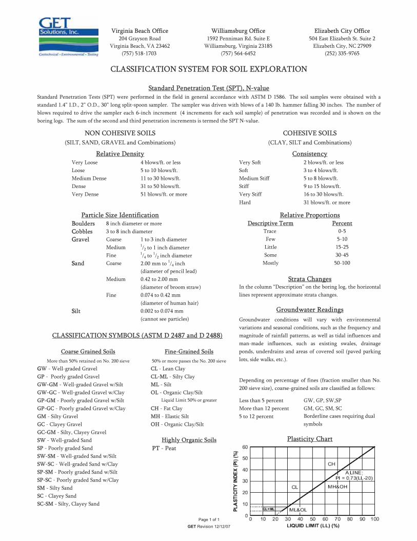
Very Loose 4 blows/ft. or less Very Soft 2 blows/ft. or lessLoose 5 to 10 blows/ft. Soft 3 to 4 blows/ft.Medium Dense 11 to 30 blows/ft. Medium Stiff 5 to 8 blows/ft.Dense 31 to 50 blows/ft. Stiff 9 to 15 blows/ft.Very Dense 51 blows/ft. or more Very Stiff 16 to 30 blows/ft.
Hard 31 blows/ft. or more
BBoulders 8 inch diameter or moreCCobbles 3 to 8 inch diameterGGravel Coarse 1 to 3 inch diameter
Medium 1/2 to 1 inch diameterFine 1/4 to 1/2 inch diameter
SSand Coarse 2.00 mm to 1/4 inch(diameter of pencil lead)
Medium 0.42 to 2.00 mm(diameter of broom straw)
Fine 0.074 to 0.42 mm(diameter of human hair)
SSilt 0.002 to 0.074 mm(cannot see particles)
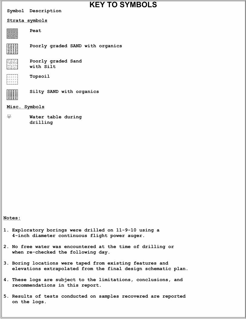
GGW - Well-graded Gravel CL - Lean ClayGP - Poorly graded Gravel CL-ML - Silty ClayGW-GM - Well-graded Gravel w/Silt ML - SiltGW-GC - Well-graded Gravel w/Clay OL - Organic Clay/SiltGP-GM - Poorly graded Gravel w/Silt Less than 5 percent GW, GP, SW,SPGP-GC - Poorly graded Gravel w/Clay CH - Fat Clay More than 12 percent GM, GC, SM, SCGM - Silty Gravel MH - Elastic Silt 5 to 12 percent GC - Clayey Gravel OH - Organic Clay/SiltGC-GM - Silty, Clayey Gravel SW - Well-graded SandSP - Poorly graded Sand PT - PeatSW-SM - Well-graded Sand w/SiltSW-SC - Well-graded Sand w/ClaySP-SM - Poorly graded Sand w/SiltSP-SC - Poorly graded Sand w/ClaySM - Silty SandSC - Clayey SandSC-SM - Silty, Clayey Sand
Particle Size Identification
Consistency
Page 1 of 1
GET Revision 12/12/07
CLASSIFICATION SYSTEM FOR SOIL EXPLORATION
Standard Penetration Test (SPT), N-value
Relative Density
NON COHESIVE SOILS(SILT, SAND, GRAVEL and Combinations)
(757) 564-6452
Elizabeth City Office504 East Elizabeth St. Suite 2
Elizabeth City, NC 27909(252) 335-9765
Standard Penetration Tests (SPT) were performed in the field in general accordance with ASTM D 1586. The soil samples were obtained with astandard 1.4” I.D., 2” O.D., 30” long split-spoon sampler. The sampler was driven with blows of a 140 lb. hammer falling 30 inches. The number ofblows required to drive the sampler each 6-inch increment (4 increments for each soil sample) of penetration was recorded and is shown on theboring logs. The sum of the second and third penetration increments is termed the SPT N-value.
Virginia Beach Office204 Grayson Road
Virginia Beach, VA 23462(757) 518-1703
Williamsburg Office1592 Penniman Rd. Suite E
Williamsburg, Virginia 23185
Coarse Grained Soils Fine-Grained Soils
Highly Organic Soils
50% or more passes the No. 200 sieve
Liquid Limit 50% or greater
TraceFew
COHESIVE SOILS(CLAY, SILT and Combinations)
Relative ProportionsDescriptive Term Percent
0-55-10
Strata ChangesIn the column “Description” on the boring log, the horizontallines represent approximate strata changes.
Groundwater Readings
LittleSome
Mostly 50-100
15-2530-45
Groundwater conditions will vary with environmentalvariations and seasonal conditions, such as the frequency andmagnitude of rainfall patterns, as well as tidal influences andman-made influences, such as existing swales, drainageponds, underdrains and areas of covered soil (paved parkinglots, side walks, etc.).
Depending on percentage of fines (fraction smaller than No.200 sieve size), coarse-grained soils are classified as follows:
Borderline cases requiring dual symbols
Plasticity Chart
CLASSIFICATION SYMBOLS (ASTM D 2487 and D 2488)
More than 50% retained on No. 200 sieve