Embed Size (px)
Citation preview
© 2009, Grontmij | Carl Bro A/S1
0
200
400
600
800
1000
1200
1400
0,00 0,02 0,04 0,06 0,08 0,10
ε1 [%]
E u / c
u [-
] Rødsand 2 Offshore Wind Farm
DGF Meeting 12-11-2009, Odense
Optimized Foundation Designby Frands Haahr & Carsten Johannesen
© 2009, Grontmij | Carl Bro A/S2
Conclusion From Soil Investigation
The present soil investigation consisting of CPTsand geotechnical boreholes with sampling but limited in-situ tests – a few shear vane tests were performed
A supplementary geotechnical campaign containing 29 boreholes with Standard Penetration Tests (SPT) were required due to shallow CPTs
Fat tertiary clay, chalk, and soft clay were recorded at some locations and no soil data stated in Design Basis
© 2009, Grontmij | Carl Bro A/S3
Results From Suppl. Soil Investigation
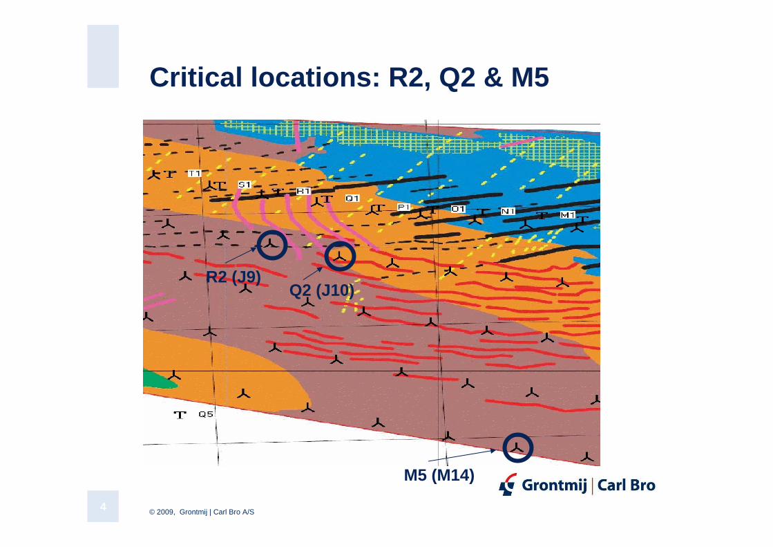
10-12 critical locations (Group 3) cf. Contractor
At 3 locations (R2, Q2 & M5): Design Basis with new soil data to be provided by E.ON cf. Contractor
1. Chalk recovered at varying depths (1.5 – 9m) below FL at position (R2) – 4 boreholes. Soil data missing for the chalk
2. Fat tertiary clay below a depth of 5.5m below FL (Q2). Missing sampling and soil data
3. Rather fat clay and ‘soft’ clay till (cu = 56 – 98 kPa) at 3.5-6.5m below FL (M5)
© 2009, Grontmij | Carl Bro A/S4
Critical locations: R2, Q2 & M5
M5 (M14)
Q2 (J10)R2 (J9)
© 2009, Grontmij | Carl Bro A/S5
E.ON’s Request to Consultant (GMCB)
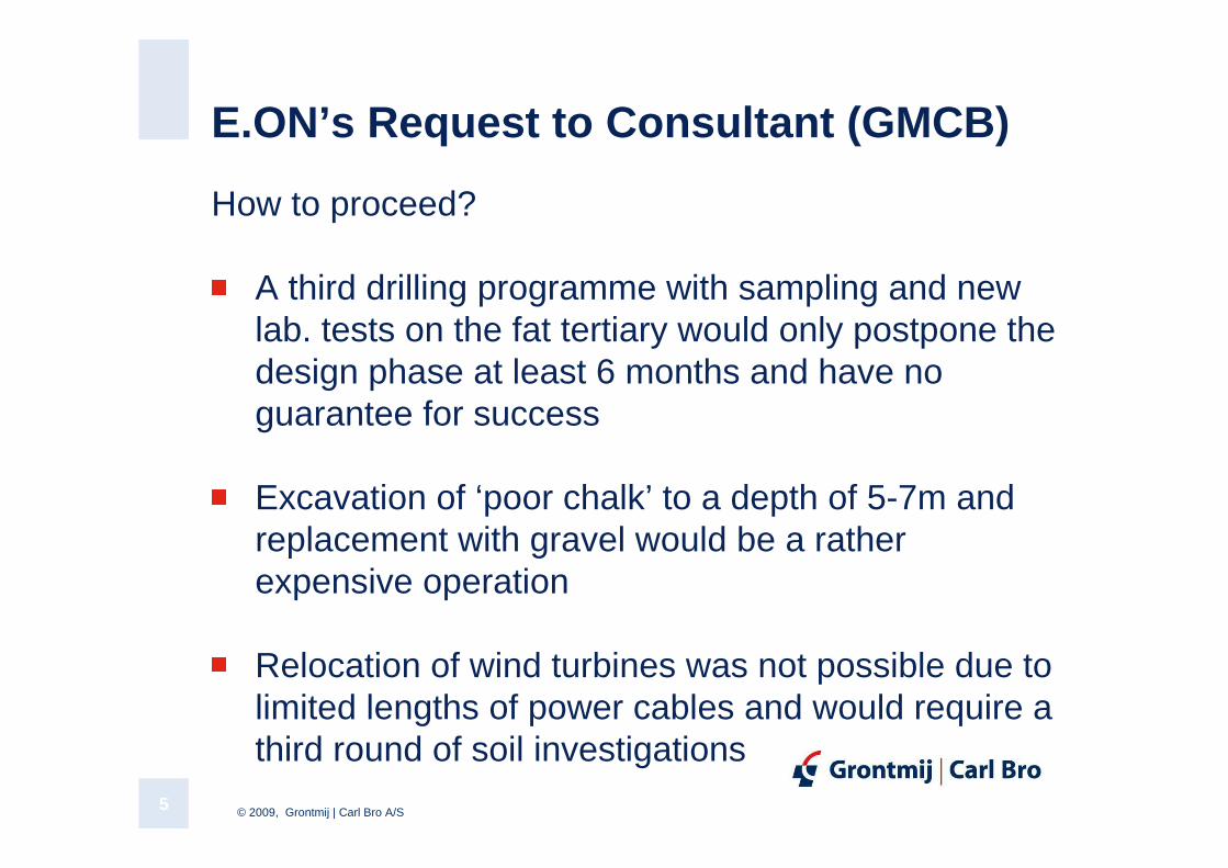
How to proceed?
A third drilling programme with sampling and new lab. tests on the fat tertiary would only postpone the design phase at least 6 months and have no guarantee for success
Excavation of ‘poor chalk’ to a depth of 5-7m and replacement with gravel would be a rather expensive operation
Relocation of wind turbines was not possible due to limited lengths of power cables and would require a third round of soil investigations
© 2009, Grontmij | Carl Bro A/S6
GMCB Proposal
Use the SPT-results from the SSI and derive cautious strength-and deformation parameters from literature, general practice/experience and recommendations in order to establish a safe Design Basis (DB) acceptable for the Contractor and his Designer. DB to be certified by DNV
SSI + continuous SPTs to a depth greater than the foundation width, cautious assessment of soil data as well as cautious evaluation of cyclic degradation for critical soil parameters, justify a reduction of the material factors
Partial factors (DNV-OS-J101):
γtanϕ’ = γc’ = 1.15 and γcu = 1.25
© 2009, Grontmij | Carl Bro A/S7
GMCB Proposal – cont.
Apply maximum ballast in chambers (hyperit) and in shaft (sand)
GMCB to exhibit “punctual care”:
1. Carry out internal calculations simultaneously in order to prove acceptable bearing capacity and limited settlements.
2. Improve calculations, where possible (2D FEM to model layering soil, 3D FEM to improve calculation of torque and effective contact area, structural calculations of GBS to improve structural stiffness and to analyze natural frequency for rocking and horizontal movements).
© 2009, Grontmij | Carl Bro A/S8
Strength- and Deformation Parameters
Design Basis without laboratory tests?
Interpretation of lab. test results is a challenge.
What may be derived from literature study?
Cyclic induced settlements of chalk and clay (new m odel)?
Experience from general practice (DK & abroad).
Engineering judgement?
Guidelines for Design of Wind Turbines (DNV/Risø, 2 005).
© 2009, Grontmij | Carl Bro A/S9
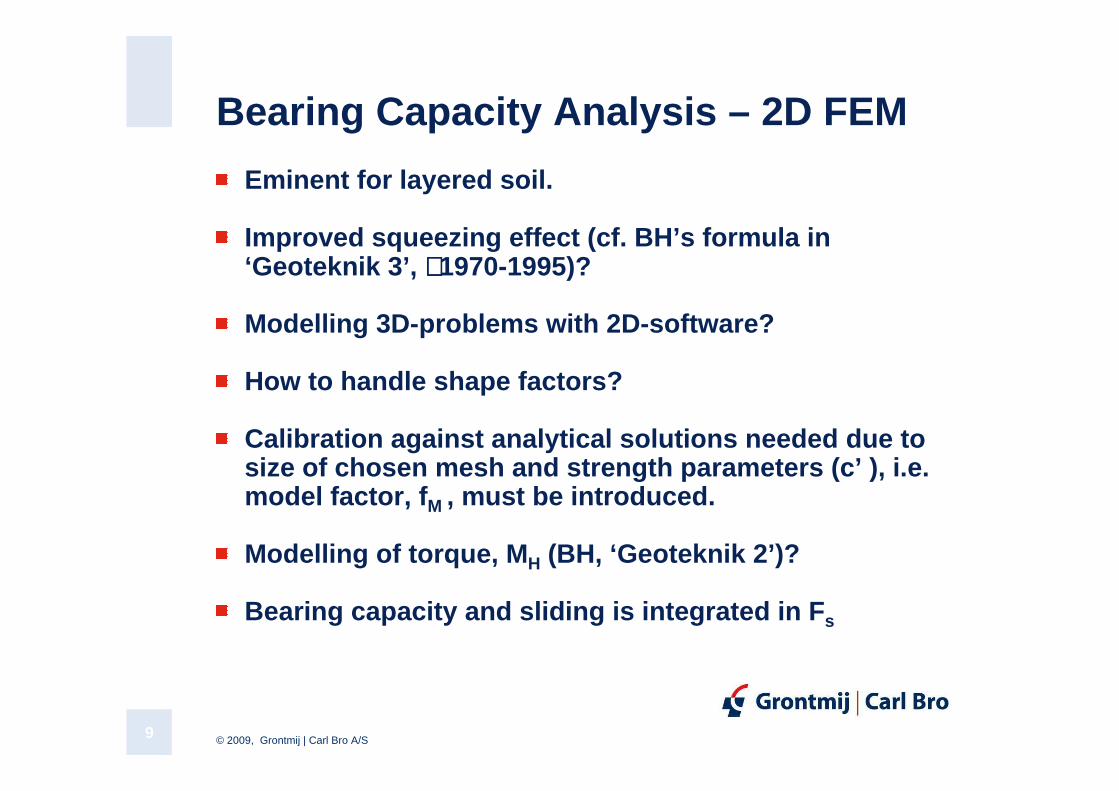
Bearing Capacity Analysis – 2D FEM
Eminent for layered soil.
Improved squeezing effect (cf. BH’s formula in ‘Geoteknik 3’, ∼∼∼∼1970-1995)?
Modelling 3D-problems with 2D-software?
How to handle shape factors?
Calibration against analytical solutions needed due to size of chosen mesh and strength parameters ( c’ ), i.e. model factor, fM , must be introduced .
Modelling of torque, MH (BH, ‘Geoteknik 2’)?
Bearing capacity and sliding is integrated in Fs
© 2009, Grontmij | Carl Bro A/S10
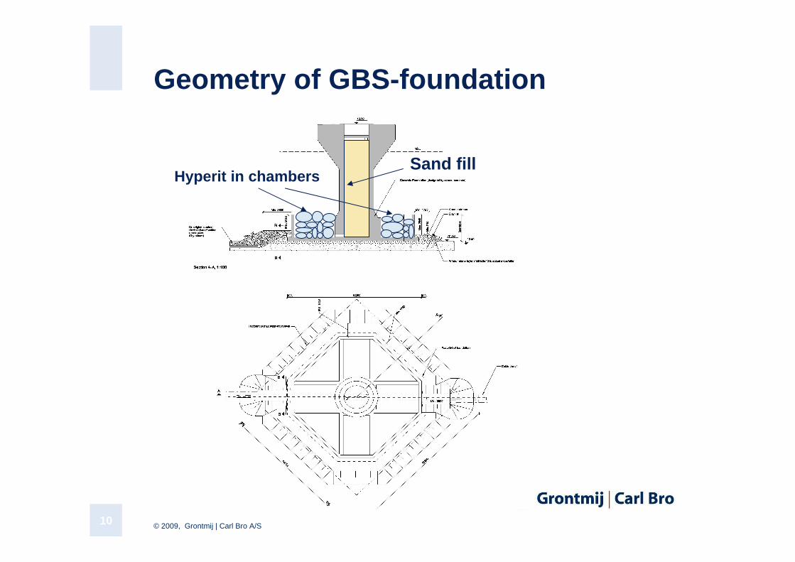
Geometry of GBS-foundation
Hyperit in chambersSand fill
© 2009, Grontmij | Carl Bro A/S11
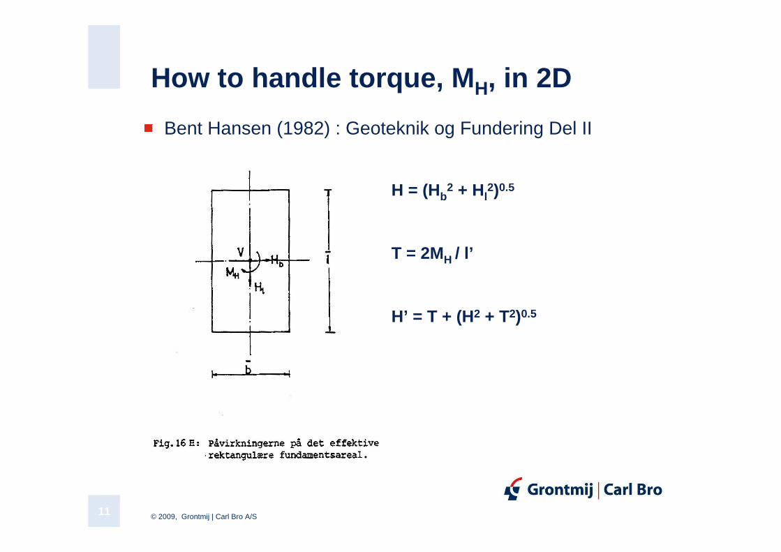
How to handle torque, MH, in 2D
Bent Hansen (1982) : Geoteknik og Fundering Del II
T = 2MH / l’
H’ = T + (H2 + T2)0.5
H = (Hb2 + Hl
2)0.5
© 2009, Grontmij | Carl Bro A/S12
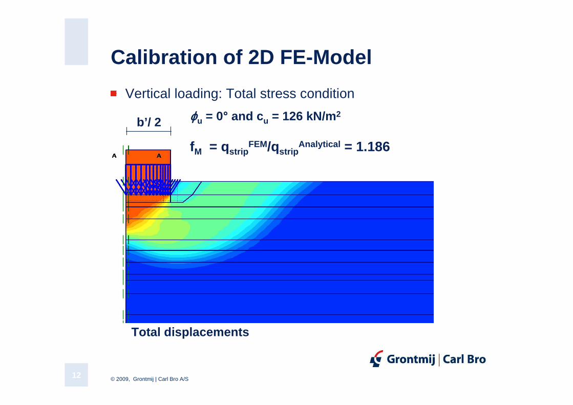
Calibration of 2D FE-Model
Vertical loading: Total stress condition
b’/ 2 ϕϕϕϕu = 0°°°° and cu = 126 kN/m 2
fM = qstripFEM/qstrip
Analytical = 1.186
Total displacements
© 2009, Grontmij | Carl Bro A/S13
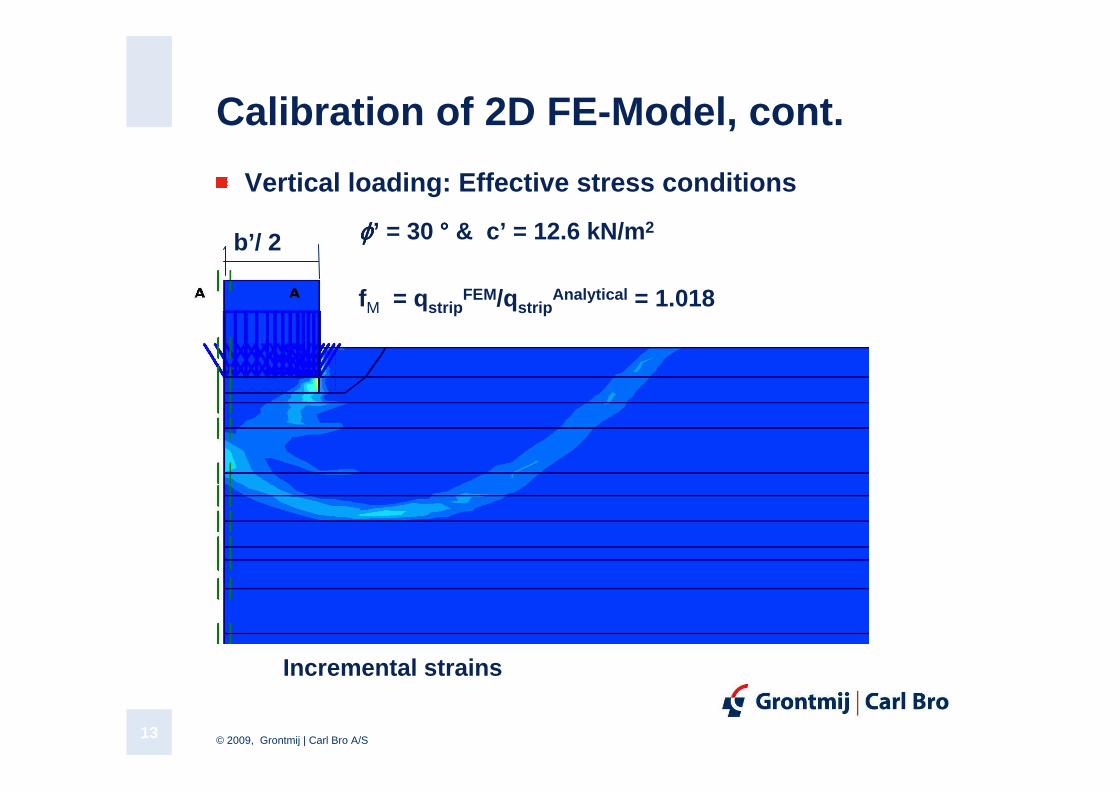
Calibration of 2D FE-Model, cont.
Vertical loading: Effective stress conditions
ϕϕϕϕ’ = 30 ° ° ° ° & c’ = 12.6 kN/m 2b’/ 2
fM = qstripFEM/qstrip
Analytical = 1.018
Incremental strains
© 2009, Grontmij | Carl Bro A/S14
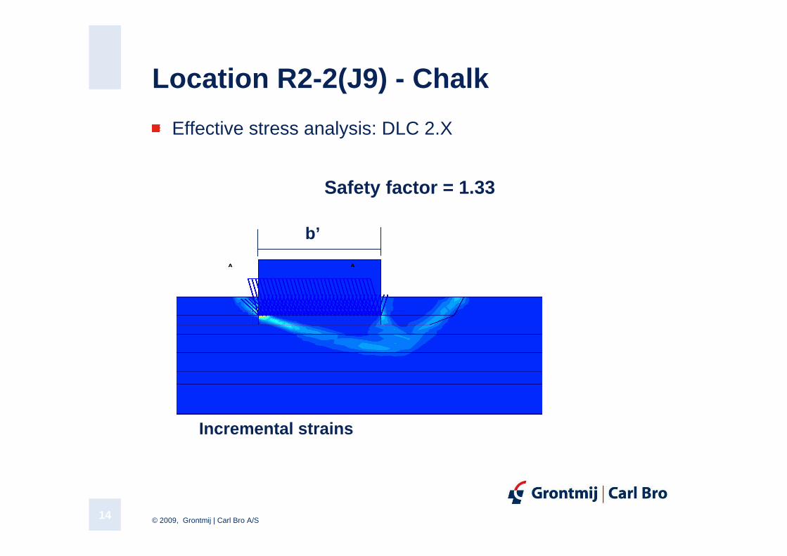
Location R2-2(J9) - Chalk
Effective stress analysis: DLC 2.X
Incremental strains
Safety factor = 1.33
b’
© 2009, Grontmij | Carl Bro A/S15
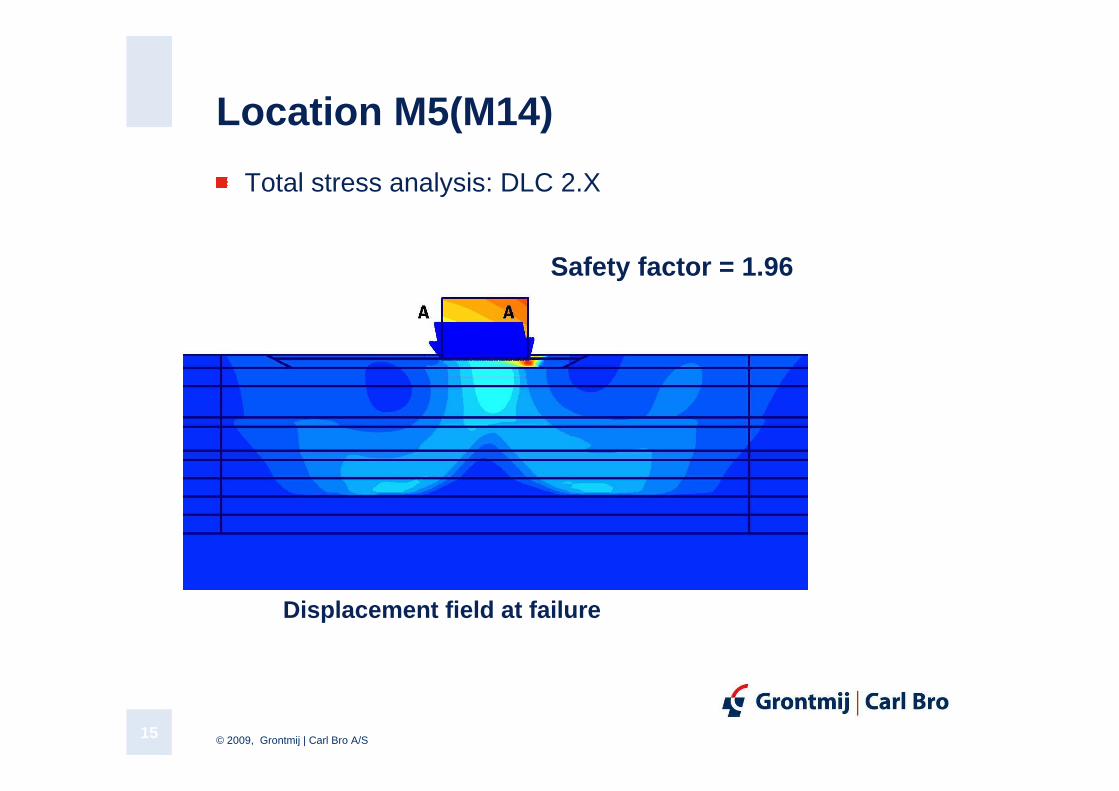
Location M5(M14)
Total stress analysis: DLC 2.X
Displacement field at failure
Safety factor = 1.96
© 2009, Grontmij | Carl Bro A/S16
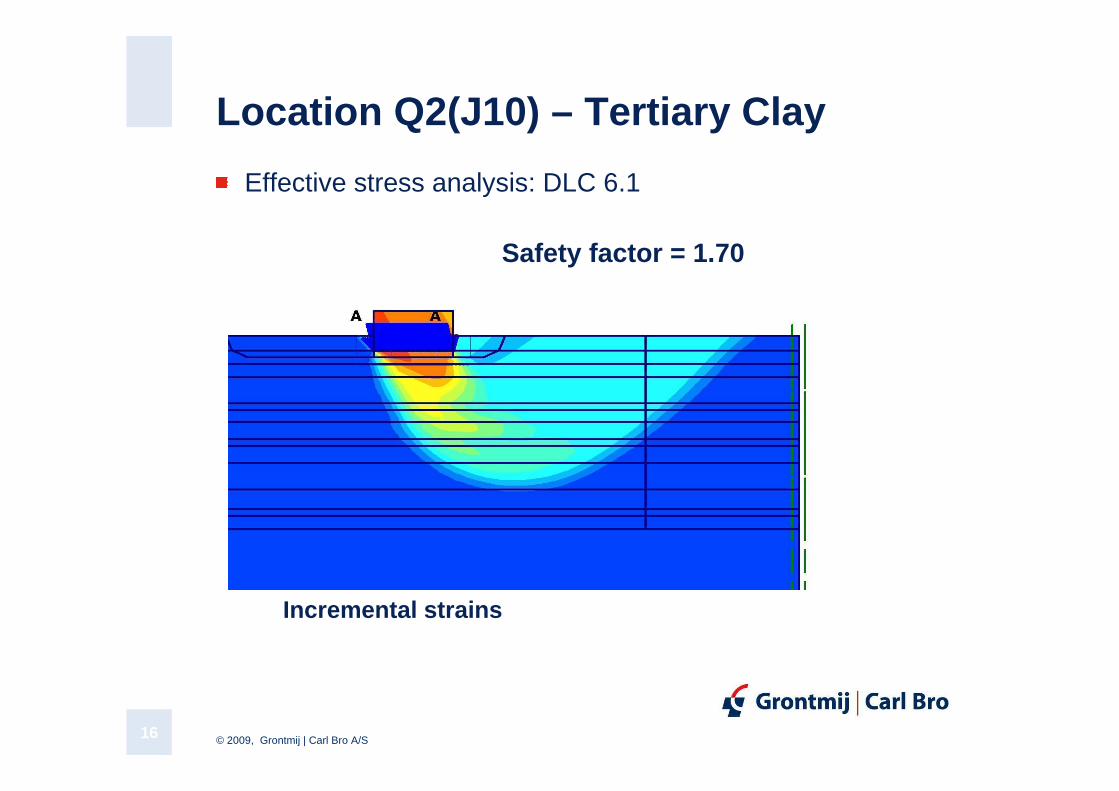
Location Q2(J10) – Tertiary Clay
Effective stress analysis: DLC 6.1
Incremental strains
Safety factor = 1.70
© 2009, Grontmij | Carl Bro A/S17
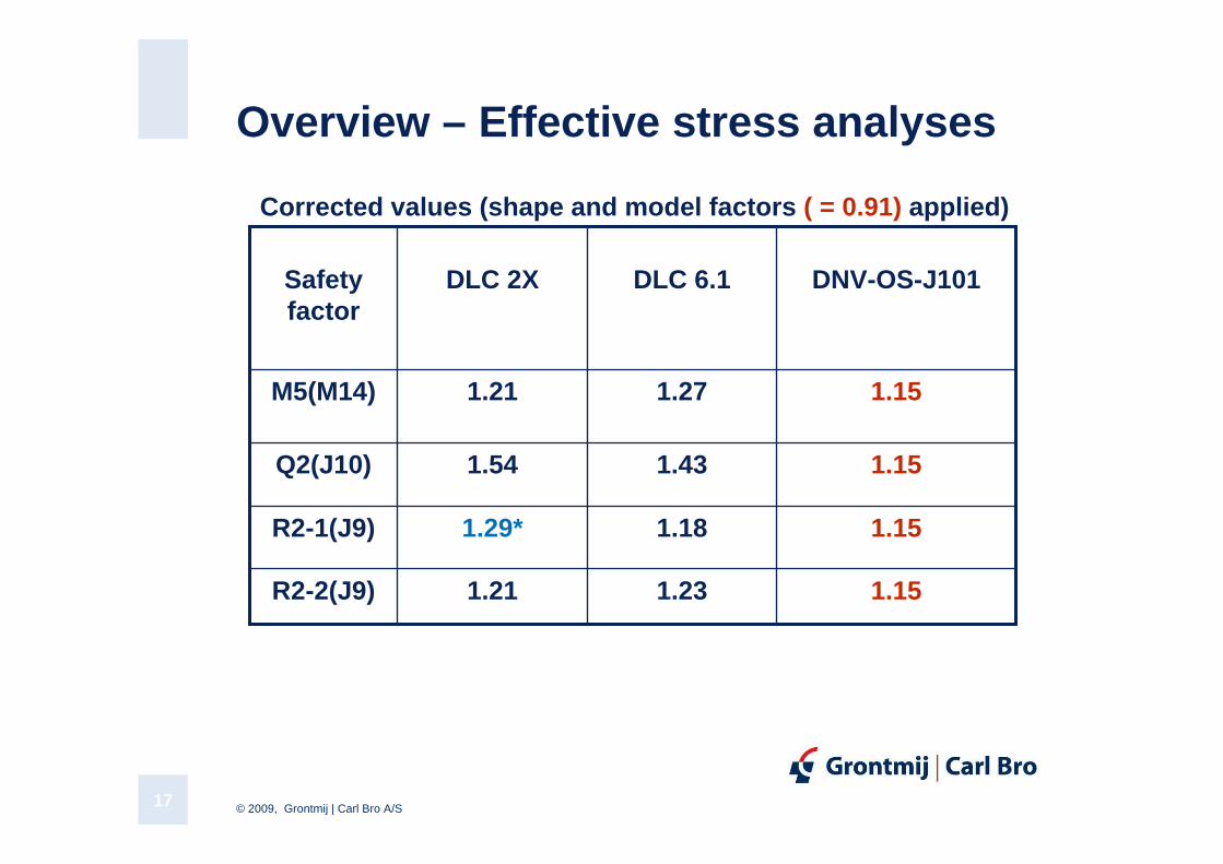
Overview – Effective stress analyses
1.23
1.18
1.43
1.27
DLC 6.1
1.151.21R2-2(J9)
1.151.21M5(M14)
1.151.29*R2-1(J9)
1.151.54Q2(J10)
DNV-OS-J101DLC 2XSafetyfactor
Corrected values (shape and model factors ( = 0.91) applied)
© 2009, Grontmij | Carl Bro A/S18
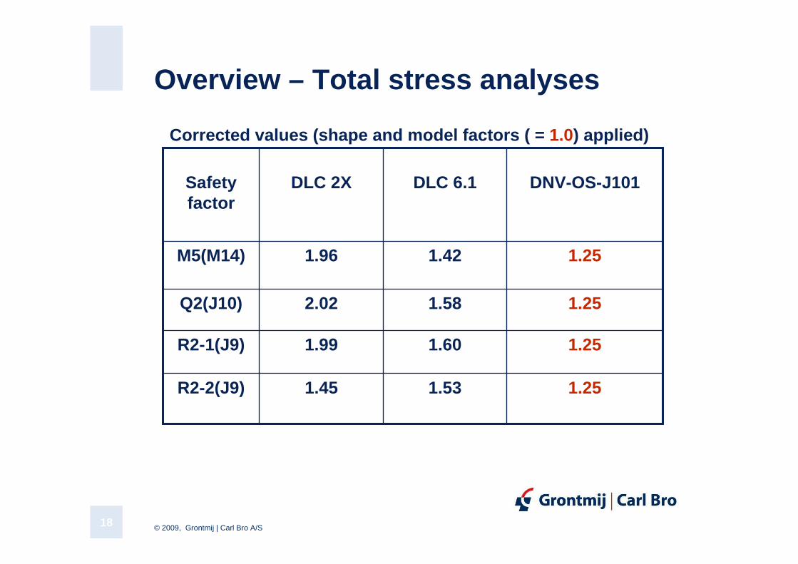
Overview – Total stress analyses
1.53
1.60
1.58
1.42
DLC 6.1
1.251.45R2-2(J9)
1.251.96M5(M14)
1.251.99R2-1(J9)
1.252.02Q2(J10)
DNV-OS-J101DLC 2XSafetyfactor
Corrected values (shape and model factors ( = 1.0) applied)
© 2009, Grontmij | Carl Bro A/S19
Conclusion: Bearing Capacity Analysis – 2D FEM
Sufficient safety (cf. DNV-OS-J101) was obtained at all three critical locations (R2, Q2 and M5)
© 2009, Grontmij | Carl Bro A/S20
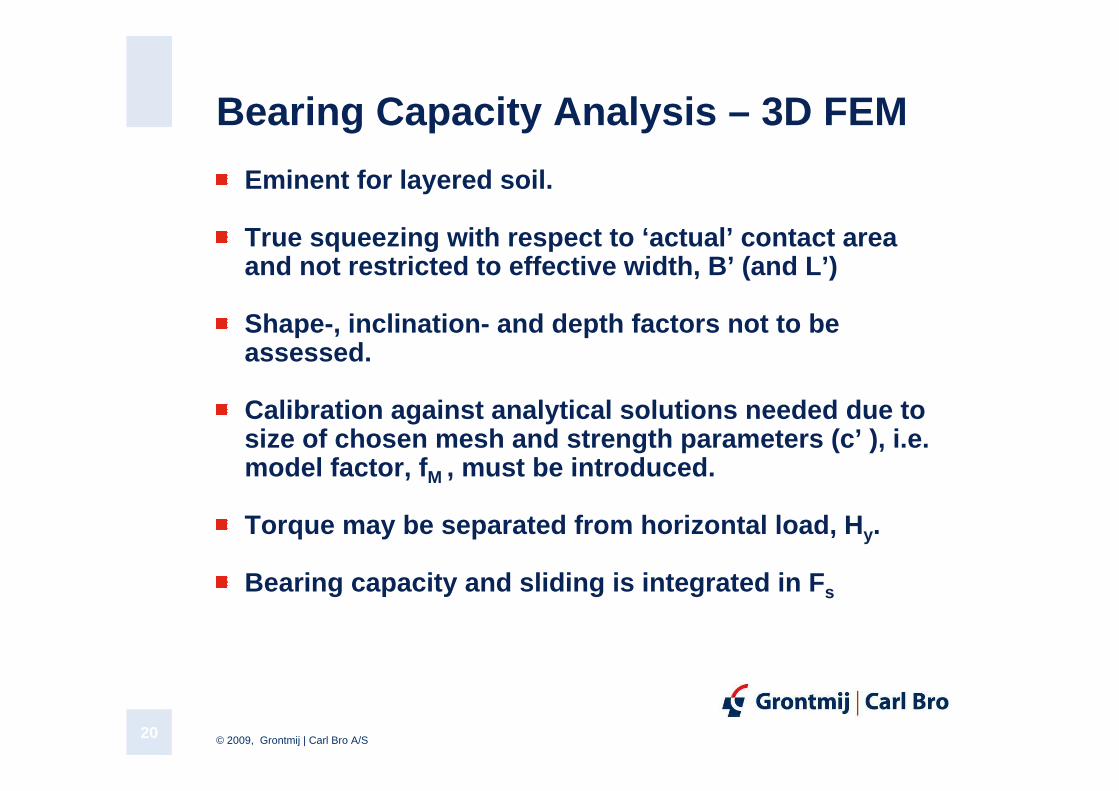
Bearing Capacity Analysis – 3D FEM
Eminent for layered soil.
True squeezing with respect to ‘actual’ contact area and not restricted to effective width, B’ (and L’)
Shape-, inclination- and depth factors not to be assessed.
Calibration against analytical solutions needed due to size of chosen mesh and strength parameters ( c’ ), i.e. model factor, fM , must be introduced .
Torque may be separated from horizontal load, Hy.
Bearing capacity and sliding is integrated in Fs
© 2009, Grontmij | Carl Bro A/S21
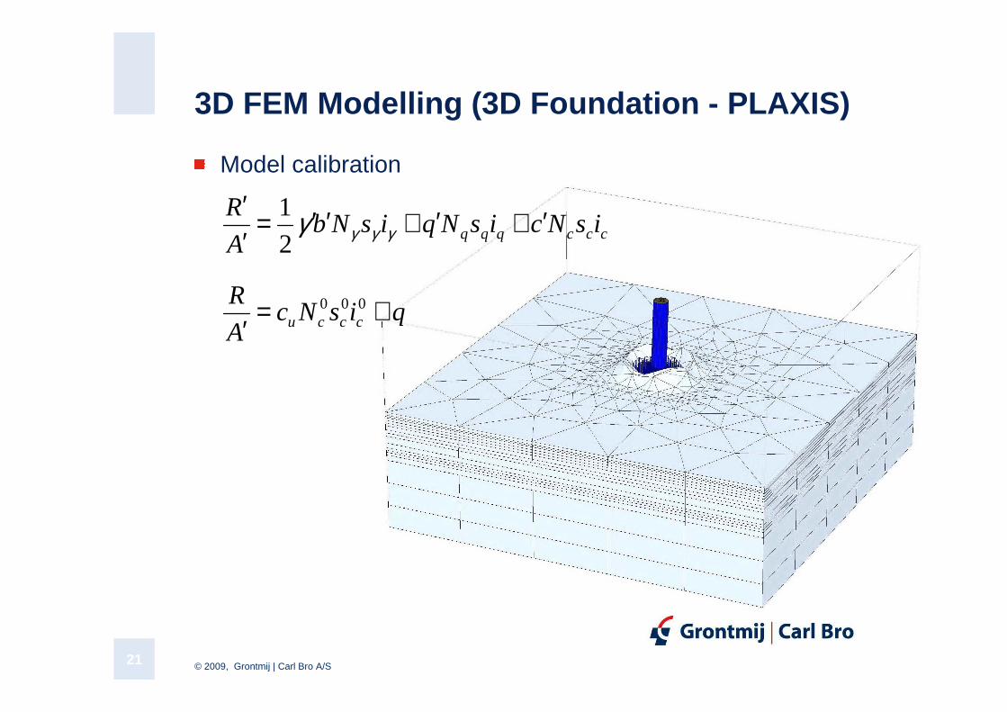
3D FEM Modelling (3D Foundation - PLAXIS)
Model calibration
cccqqq isNcisNqisNbA
R ′+′+′′=′′
γγγγ2
1
qisNcA
Rcccu +=
′000
© 2009, Grontmij | Carl Bro A/S22
0,0
0,2
0,4
0,6
0,8
1,0
1,2
1,4
1,6
0,0 0,1 0,2 0,3 0,4 0,5Total displacement [m]
Fac
tor
of s
afet
y
PLAXIS
Bearing capacity formula
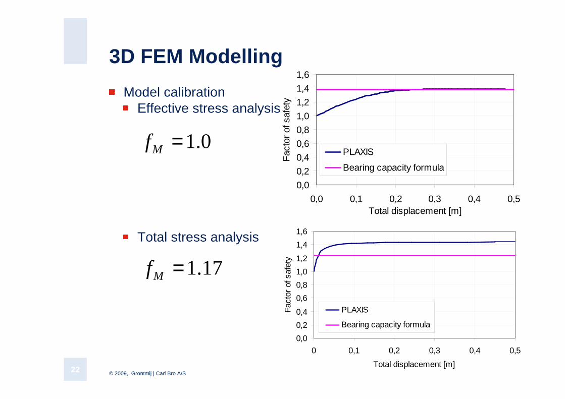
3D FEM Modelling
Model calibrationEffective stress analysis
Total stress analysis
0,0
0,2
0,4
0,6
0,8
1,0
1,2
1,4
1,6
0 0,1 0,2 0,3 0,4 0,5
Total displacement [m]
Fac
tor
of s
afet
y
PLAXIS
Bearing capacity formula
0.1=Mf
17.1=Mf
© 2009, Grontmij | Carl Bro A/S23
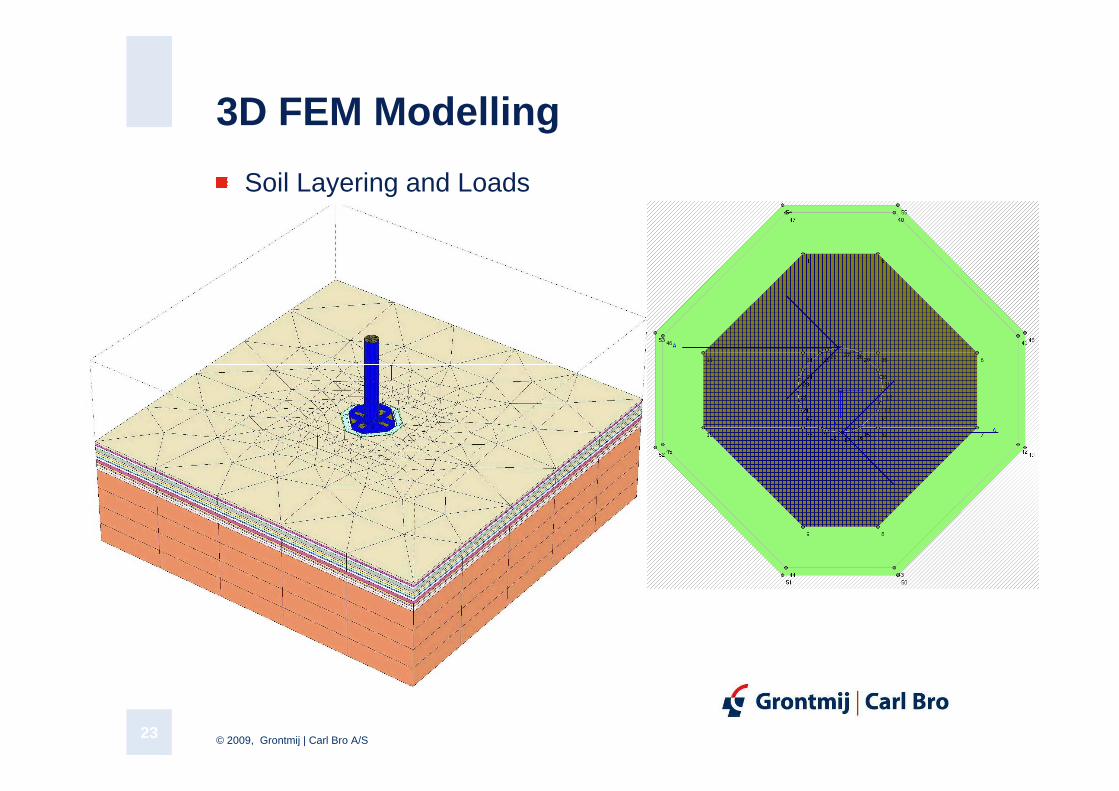
3D FEM Modelling
Soil Layering and Loads
© 2009, Grontmij | Carl Bro A/S24
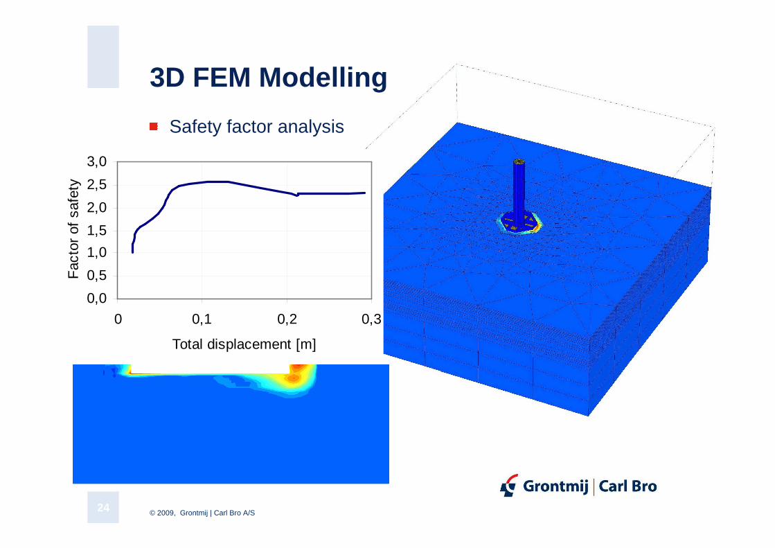
3D FEM Modelling
Safety factor analysis
0,0
0,5
1,0
1,5
2,0
2,5
3,0
0 0,1 0,2 0,3
Total displacement [m]
Fac
tor
of s
afet
y
© 2009, Grontmij | Carl Bro A/S25
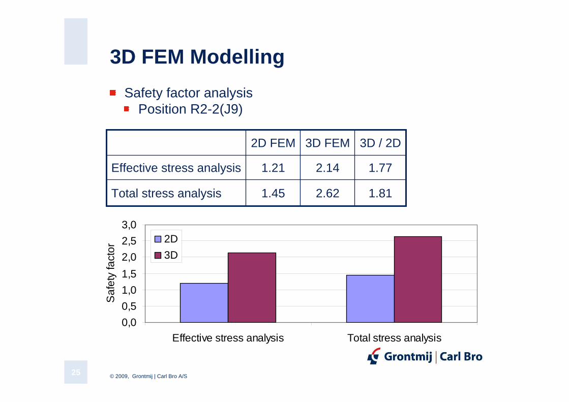
3D FEM Modelling
Safety factor analysisPosition R2-2(J9)
1.812.621.45Total stress analysis
1.772.141.21Effective stress analysis
3D / 2D3D FEM2D FEM
0,0
0,5
1,0
1,5
2,0
2,5
3,0
Effective stress analysis Total stress analysis
Saf
ety
fact
or
2D
3D
© 2009, Grontmij | Carl Bro A/S26
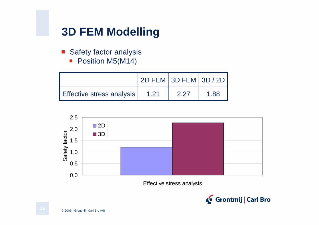
3D FEM Modelling
Safety factor analysisPosition M5(M14)
1.882.271.21Effective stress analysis
3D / 2D3D FEM2D FEM
0,0
0,5
1,0
1,5
2,0
2,5
Effective stress analysis
Saf
ety
fact
or
2D
3D
© 2009, Grontmij | Carl Bro A/S27
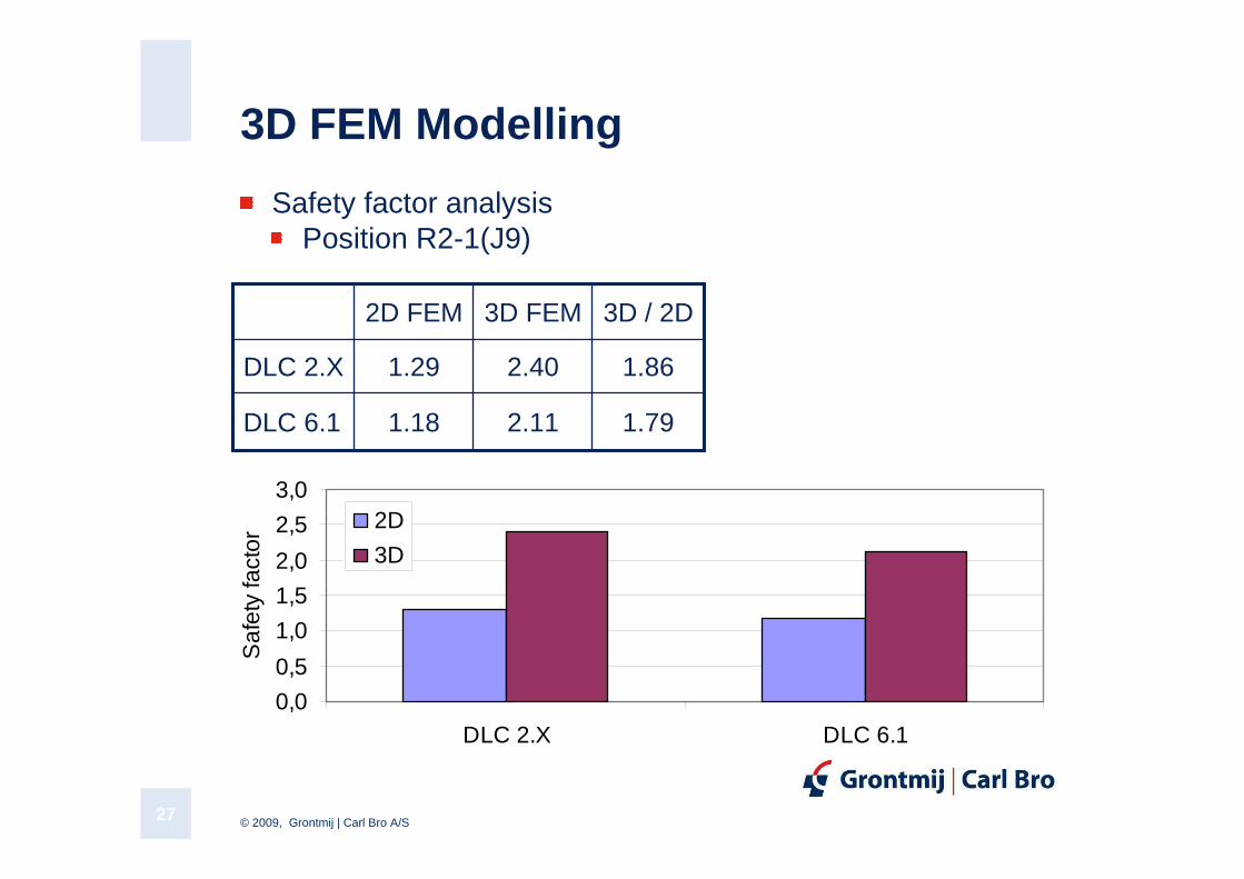
3D FEM Modelling
Safety factor analysisPosition R2-1(J9)
1.792.111.18DLC 6.1
1.862.401.29DLC 2.X
3D / 2D3D FEM2D FEM
0,0
0,5
1,0
1,5
2,0
2,5
3,0
DLC 2.X DLC 6.1
Saf
ety
fact
or
2D
3D
© 2009, Grontmij | Carl Bro A/S28
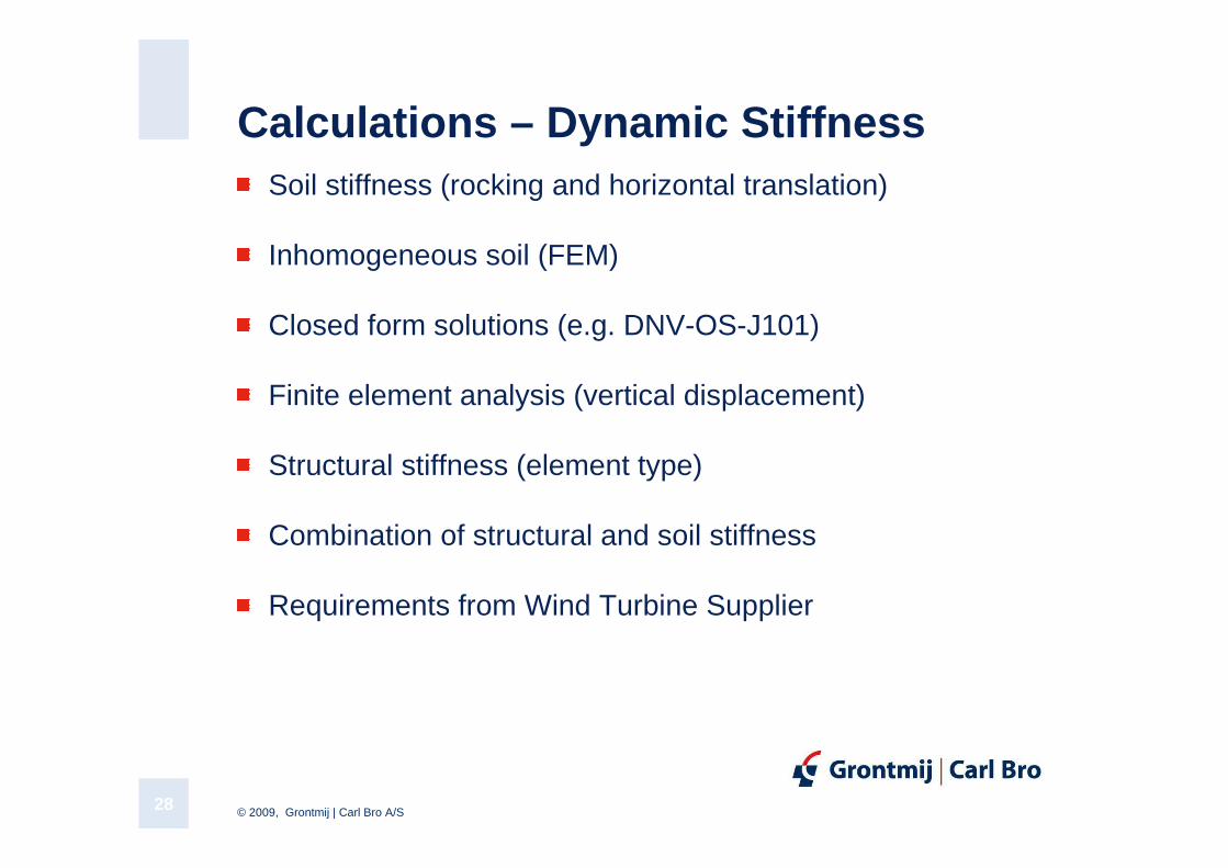
Calculations – Dynamic StiffnessSoil stiffness (rocking and horizontal translation)
Inhomogeneous soil (FEM)
Closed form solutions (e.g. DNV-OS-J101)
Finite element analysis (vertical displacement)
Structural stiffness (element type)
Combination of structural and soil stiffness
Requirements from Wind Turbine Supplier
© 2009, Grontmij | Carl Bro A/S29
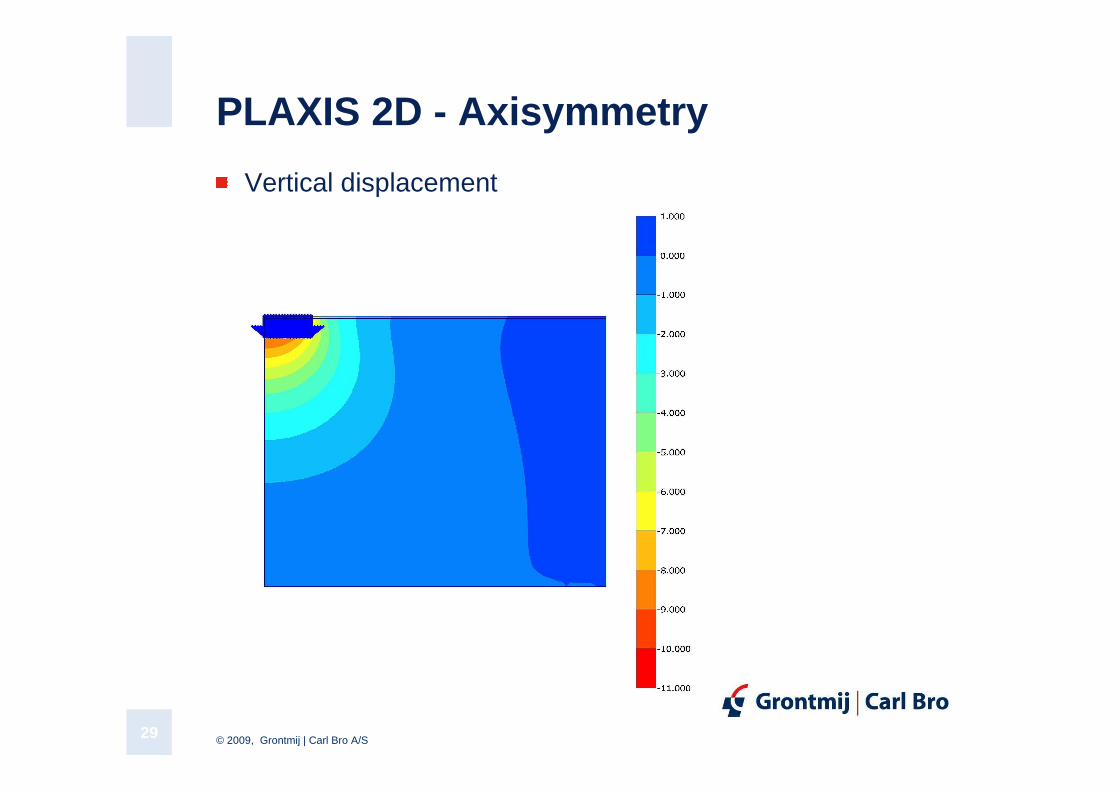
PLAXIS 2D - Axisymmetry
Vertical displacement
© 2009, Grontmij | Carl Bro A/S30
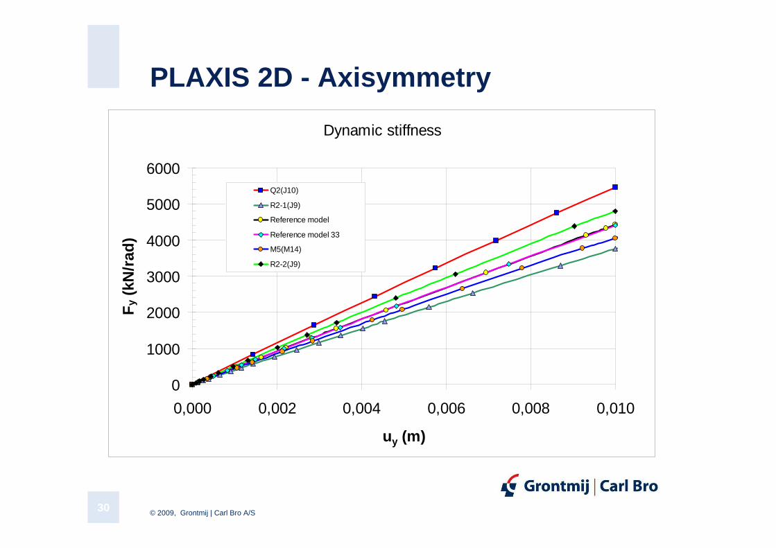
PLAXIS 2D - Axisymmetry
Dynamic stiffness
0
1000
2000
3000
4000
5000
6000
0,000 0,002 0,004 0,006 0,008 0,010
uy (m)
Fy
(kN
/rad
)
Q2(J10)
R2-1(J9)
Reference model
Reference model 33
M5(M14)
R2-2(J9)
© 2009, Grontmij | Carl Bro A/S31
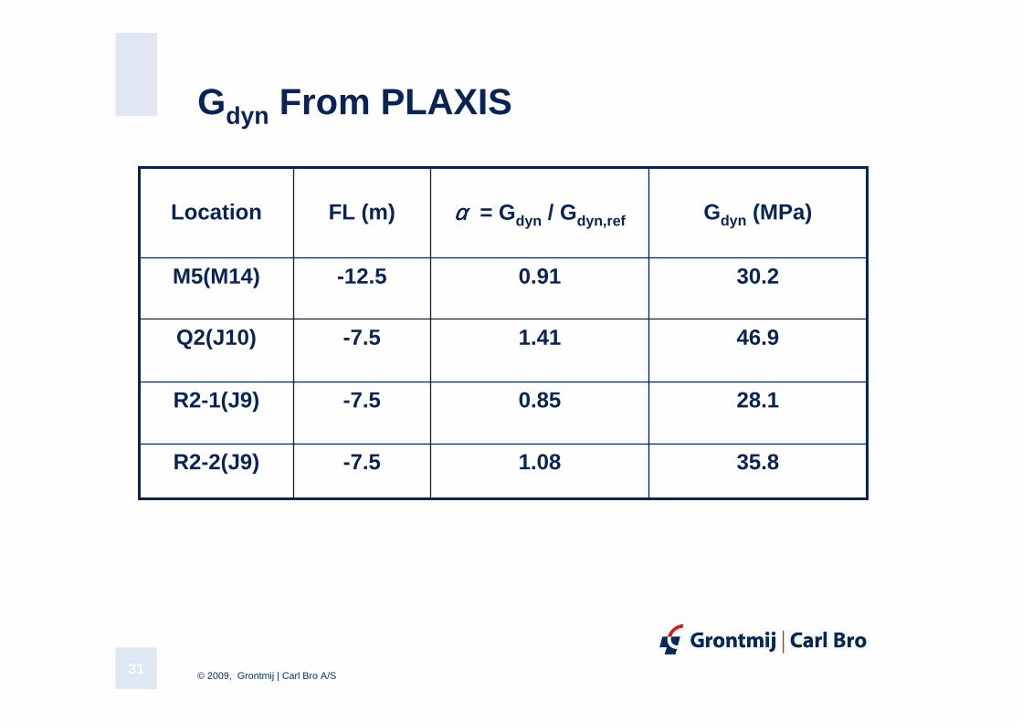
Gdyn From PLAXIS
30.20.91-12.5M5(M14)
35.81.08-7.5R2-2(J9)
28.10.85-7.5R2-1(J9)
46.91.41-7.5Q2(J10)
Gdyn (MPa)αααα = Gdyn / Gdyn,refFL (m)Location
© 2009, Grontmij | Carl Bro A/S32
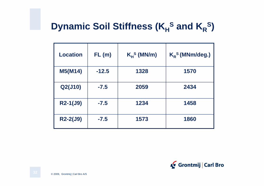
Dynamic Soil Stiffness ( KHS and KR
S)
15701328-12.5M5(M14)
18601573-7.5R2-2(J9)
14581234-7.5R2-1(J9)
24342059-7.5Q2(J10)
KRS (MNm/deg.)KH
S (MN/m)FL (m)Location
© 2009, Grontmij | Carl Bro A/S33
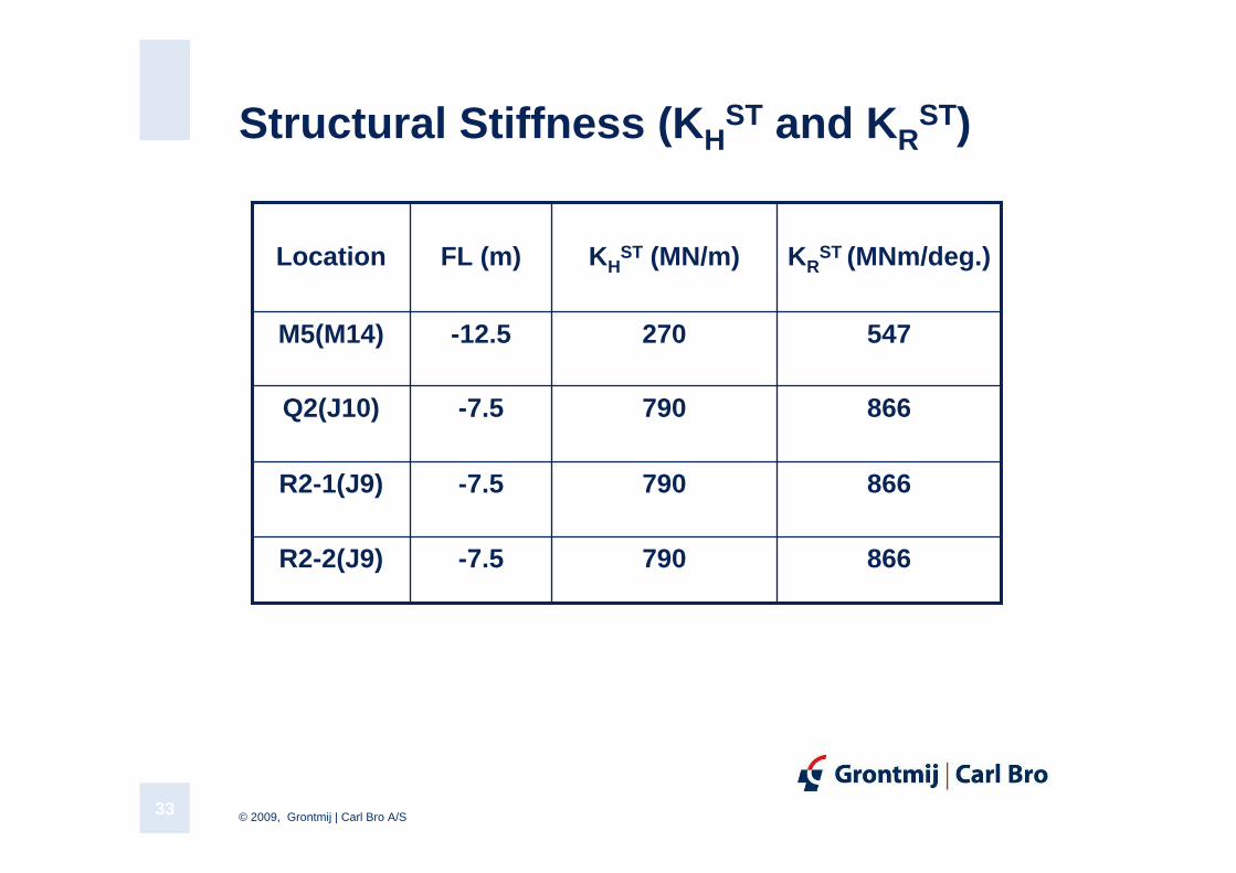
Structural Stiffness ( KHST and KR
ST)
547270-12.5M5(M14)
866790-7.5R2-2(J9)
866790-7.5R2-1(J9)
866790-7.5Q2(J10)
KRST (MNm/deg.)KH
ST (MN/m)FL (m)Location
© 2009, Grontmij | Carl Bro A/S34
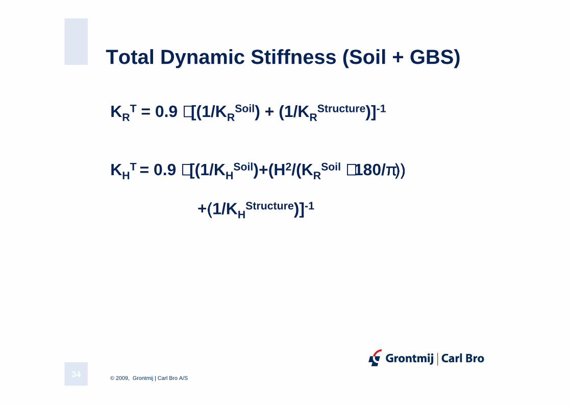
Total Dynamic Stiffness (Soil + GBS)
KRT = 0.9 ⋅⋅⋅⋅ [(1/KR
Soil ) + (1/KRStructure )]-1
KHT = 0.9 ⋅⋅⋅⋅ [(1/KH
Soil )+(H2/(KRSoil ⋅⋅⋅⋅ 180/ππππ)) )) )) ))
+(+(+(+(1/KHStructure )]-1
© 2009, Grontmij | Carl Bro A/S35
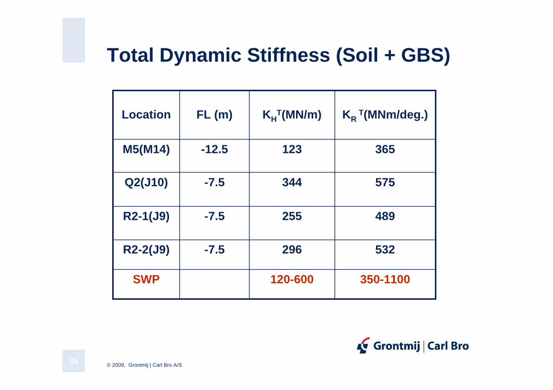
Total Dynamic Stiffness (Soil + GBS)
532296-7.5R2-2(J9)
365123-12.5M5(M14)
350-1100120-600SWP
489255-7.5R2-1(J9)
575344-7.5Q2(J10)
KR T(MNm/deg.)KH
T(MN/m)FL (m)Location
© 2009, Grontmij | Carl Bro A/S36
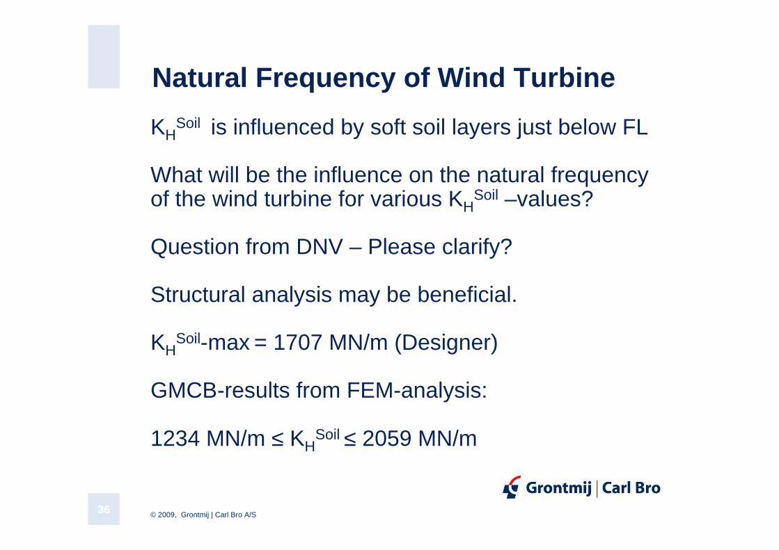
Natural Frequency of Wind Turbine
KHSoil is influenced by soft soil layers just below FL
What will be the influence on the natural frequencyof the wind turbine for various KH
Soil –values?
Question from DNV – Please clarify?
Structural analysis may be beneficial.
KHSoil-max = 1707 MN/m (Designer)
GMCB-results from FEM-analysis:
1234 MN/m ≤ KHSoil ≤ 2059 MN/m
© 2009, Grontmij | Carl Bro A/S37
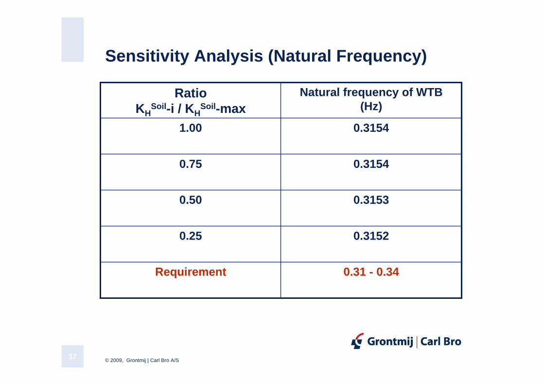
Sensitivity Analysis (Natural Frequency)
0.31520.25
0.31530.50
0.31 - 0.34Requirement
0.31540.75
0.31541.00
Natural frequency of WTB(Hz)
RatioKH
Soil -i / KHSoil -max
© 2009, Grontmij | Carl Bro A/S38
Natural Frequency of Wind Turbine, cont.
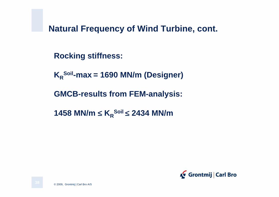
Rocking stiffness:
KRSoil -max = 1690 MN/m (Designer)
GMCB-results from FEM-analysis:
1458 MN/m ≤≤≤≤ KRSoil ≤≤≤≤ 2434 MN/m
© 2009, Grontmij | Carl Bro A/S39
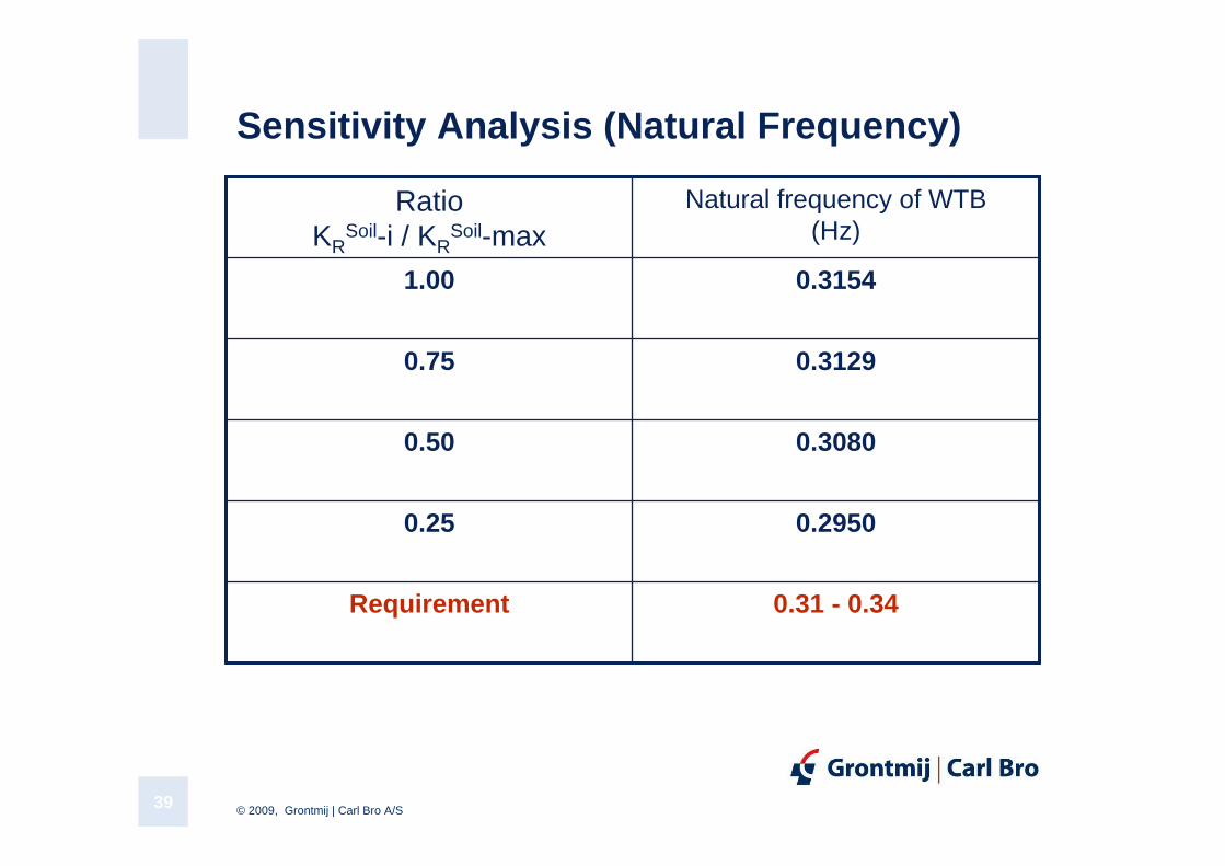
Sensitivity Analysis (Natural Frequency)
0.29500.25
0.30800.50
0.31 - 0.34Requirement
0.31290.75
0.31541.00
Natural frequency of WTB(Hz)
RatioKR
Soil-i / KRSoil-max
© 2009, Grontmij | Carl Bro A/S40
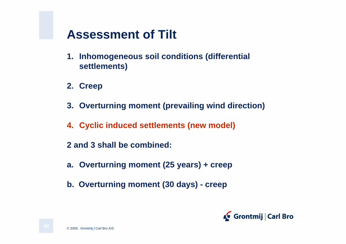
Assessment of Tilt
1. Inhomogeneous soil conditions (differential settlements)
2. Creep
3. Overturning moment (prevailing wind direction)
4. Cyclic induced settlements (new model)
2 and 3 shall be combined:
a. Overturning moment (25 years) + creep
b. Overturning moment (30 days) - creep
© 2009, Grontmij | Carl Bro A/S41
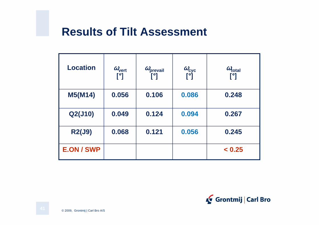
Results of Tilt Assessment
0.056
0.094
0.086
ϖϖϖϖcyc[°][°][°][°]
0.2480.1060.056M5(M14)
< 0.25E.ON / SWP
0.2450.1210.068R2(J9)
0.2670.1240.049Q2(J10)
ϖϖϖϖtotal[°][°][°][°]
ϖϖϖϖprevail[°][°][°][°]
ϖϖϖϖvert[°][°][°][°]
Location
© 2009, Grontmij | Carl Bro A/S42
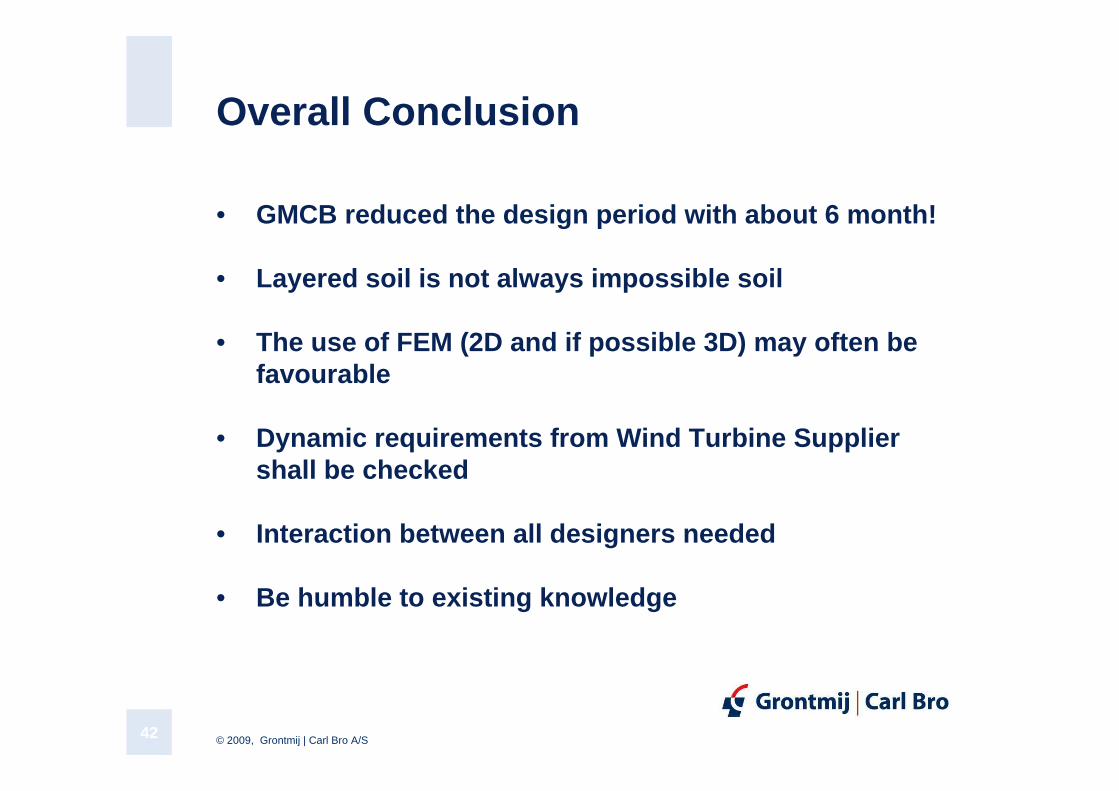
Overall Conclusion
• GMCB reduced the design period with about 6 month!
• Layered soil is not always impossible soil
• The use of FEM (2D and if possible 3D) may often be favourable
• Dynamic requirements from Wind Turbine Supplier shall be checked
• Interaction between all designers needed
• Be humble to existing knowledge