Embed Size (px)
Citation preview
Rohrsysteme nach dem Baukasten-PrinzipNeu! Jetzt Losflanschkatalog integriert.
Modular pipework systemsNew! Now includes flanged pipework.
Système de tuyauterie modulaireNouveau! Avec le programme à brides tournantes.
ProduktkatalogEUROPAS NR. 1 IN ROHRSYSTEMEN

2
Allgemeine InformationenSonderfertigung
Werkstoffe, Oberflächen, Durchmesser
General informationSpecial requirements
Materials, surfaces, diameters
8
7
6
5
4
3
2
1
9
10
12
13
14
VerbindungselementeConnecting componentsEléments de liaison
RohrePipesTuyaux
Bogen und SegmenteBends & segmentsCoudes et secteurs
AbzweigstückeBranch piecesTuyaux de branchement
ÜbergängeTransition piecesPièces d’adaptation
InspektionsrohrteileInspection componentsPièces d’inspection
Regel- und AbsperrorganeRegulators & shut-off valvesEléments de régulation ou de fermeture
Zwei-Wege-VerteilungenTwo-way distributorsDistributeurs 2 voies
Mehrwege-VerteilungenMulti-way distributorsDistributeurs multi-voies
Zubehör und BefestigungselementeAccessories & fittingsAccessoires et éléments de fixation
Verschiedenes / SonstigesMiscellaneous & SpecialsDivers
Rohr- und Formteilemit Losflanschen
BestellnummernschlüsselAllgemeine Lieferungs- und ZahlungsbedingungenAlphabetischer Index
Informations généralesPièces spéciales
Matériau, traitement de surface, diamètres
Übersicht VerbindungenOverview of connectionsRésumé des liaisons
Quick Connect SpannringeQuick Connect pull-ringsColliers Quick Connect
RohrePipesTuyaux
AnschweißendenWelding endsCollerettes à souder
Übersicht RohrbogenOverview of bendsRésumé des coudes
RohrbogenBendsCoudes
T-StückeT-piecesPièces en T
GabelstückeForksCulottes droites
KonusstückeCone piecesRéductions
AnschlussstutzenConnecting flangesTubulures de raccordement
KontrollrohreInspection-pipesConduit à regard
ReinigungsrohreCleaning-pipesTuyaux de nettoyage
Rohrdrossel-/ AbsperrklappenThrottle-/ Shut-off valvesVannes à clapet
Hinweise AbsperrklappenNotes on shut-off valvesIndications sur vannes à clapet
Übersicht EinsatzgebieteSummary of applicationsVue d’ensemble critères d’utilisation
Klappkästen mit KragenTwo-way-valvesBoîtes à clapet
DrehrohrverteilerTurn-head distributorsDistributeurs rotatifs
DoppeldrehrohrverteilerTwin-pipe turn-head distributorsDistributeurs rotatifs double
FlanscheFlangesBrides
BördelvorrichtungenFlanging toolsAppareil pour border
RohrkugelgelenkePipe balls jointsRotules
PlexiglasrohrePlexiglass pipesTuyaux de plexiglas
Modular pipework systemswith loose flanges
Tuyaux et pièces de formeavec brides tournantes
Order-no-codeGeneral terms of delivery and paymentAlphabetical index
Code des Nos d’articlesConditions générales de venteet de paiementIndex alphabétique
11
3
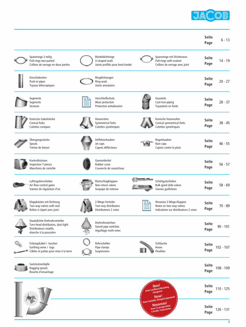
Spannringe 2-teiligPull-rings two-partedColliers de serrage en deux parties
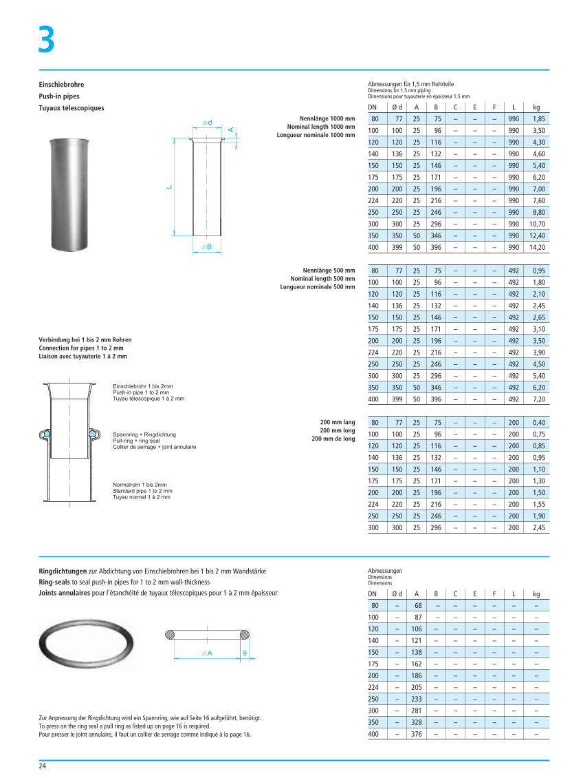
EinschiebrohrePush-in pipesTuyaux télescopiques
SegmenteSegmentsSecteurs
Konische GabelstückeConical forksCulottes coniques
ÜbergangsstückeSpoutsTrémie de liaison
KontrollstutzenInspection T-piecesManchons de contrôle
LuftregulierschieberAir flow control gatesVannes de régulation d’air
Klappkästen mit DichtungTwo-way-valves with sealBoîtes à clapet avec joint
Staubdichte DrehrohrverteilerTurn-head distributors, dust tight Distributeurs rotatifs, étanche á la poussière
Erdungskabel / -laschenEarthing wires / -lugsCâbles et pattes pour mise à la terre
SackstutzentöpfeBagging spoutsBouche d’ensachage
BördeldichtringeU-shaped sealsJoints profilés pour bord tombé
RingdichtungenRing-sealsJoints annulaires
VerschleißschutzWear protectionProtection antiabrasion
HosenrohreSymmetrical forksCulottes symétriques
DeflektorhaubenJet capsCapots déflecteurs
GummideckelRubber coverCouvercle de caoutchouc
RückschlagklappenNon-return valvesSoupape de retenue
2-Wege-VerteilerTwo-way distributorsDistributeurs 2 voies
DrehrohrweichenSwivel pipe switchesAiguillage multi-voies
RohrschellenPipe-clampsSuspensions
SeitePage
SeitePage
SeitePage
SeitePage
SeitePage
SeitePage
SeitePage
SeitePage
SeitePage
SeitePage
SeitePage
SeitePage
SeitePage
SeitePage
6 - 13
14 - 19
20 - 27
28 - 37
38 - 45
46 - 55
56 - 57
58 - 69
70 - 89
90 - 101
102 - 107
108 - 109
110 - 125
126 - 131
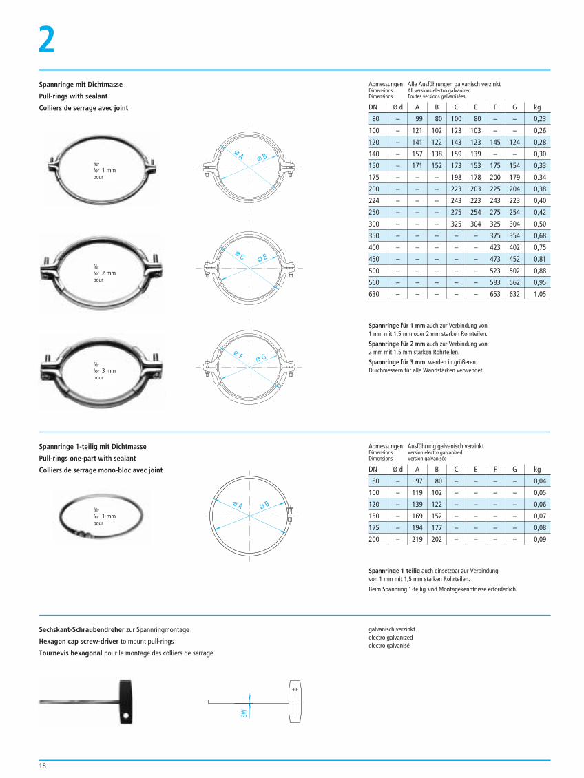
Spannringe mit DichtmassePull-rings with sealantColliers de serrage avec joint
GussteileCast-iron pipingTuyauterie en fonte
Konische HosenrohreConical symmetrical forksCulottes symétriques
RegenhaubenRain capsCapots contre la pluie
SchüttgutschieberBulk good slide valvesVannes guillotines
Hinweise 2-Wege-KlappenNotes on two-way-valvesIndications sur distributeurs 2 voies
SchläucheHosesFlexibles
Neu!
Jetzt Losflanschkatalog
integriert
New!
Now includes flanged pipework
Nouveau!
Avec le programme
à brides tournantes
19601924
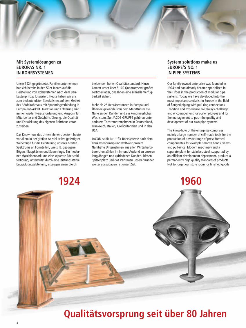
Mit Systemlösungen zuEUROPAS NR. 1IN ROHRSYSTEMEN
System solutions make usEUROPE‘S NO. 1IN PIPE SYSTEMS
Unser 1924 gegründetes Familienunternehmenhat sich bereits in den 50er Jahren auf dieHerstellung von Rohrsystemen nach dem Bau-kastenprinzip fokussiert. Heute haben wir unszum bedeutendsten Spezialisten auf dem Gebietdes Bördelrohrbaus mit Spannringverbindung inEuropa entwickelt. Tradition und Erfahrung sindimmer wieder Herausforderung und Ansporn fürMitarbeiter und Geschäftsführung, die Qualitätund Entwicklung des eigenen Rohrbaus voran-zutreiben.
Das Know-how des Unternehmens besteht heutevor allem in der großen Anzahl selbst gefertigterWerkzeuge für die Herstellung unseres breitenSpektrums an Formteilen, wie z. B. gezogeneBögen, Klappkästen und Spannringe. Ein moder-ner Maschinenpark und eine separate Edelstahl-fertigung, unterstützt durch eine leistungsstarkeEntwicklungsabteilung, erzeugen einen gleich
bleibenden hohen Qualitätsstandard. Hinzukommt unser über 5.100 Quadratmeter großesFertigteillager, das Ihnen eine schnelle Verfüg-barkeit sichert.
Mehr als 25 Repräsentanzen in Europa undÜbersee gewährleisten dem Marktführer dieNähe zu den Kunden und ein kontinuierlichesWachstum. Zur JACOB GRUPPE gehören unteranderem Tochterunternehmen in Deutschland,Frankreich, Italien, Großbritannien und in denUSA.
JACOB ist die Nr. 1 für Rohrsysteme nach demBaukastenprinzip und weltweit präsent.Namhafte Unternehmen aus allen Wirtschafts-bereichen zählen im In- und Ausland zu unserenlangjährigen und zufriedenen Kunden. DiesenSpitzenplatz und das Vertrauen unserer Kundenweiter auszubauen, ist unser Ziel.
Our family-owned enterprise was founded in1924 and had already become specialized inthe Fifties in the production of modular pipesystems. Today we have developed into themost important specialist in Europe in the fieldof flanged piping with pull-ring connections.Tradition and experience are always challengeand encouragement for our employees and forthe management to push the quality anddevelopment of our own pipe systems.
The know-how of the enterprise comprisesmainly a large number of self-made tools for theproduction of a wide range of press-formedcomponentes for example smooth bends, valvesand pull-rings. Modern machinery and aseparate plant for stainless steel, supported byan efficient development department, produce apermanently high quality standard of products.Not to forget our store room for finished goods
Qualitätsvorsprung seit über 80 Jahren4
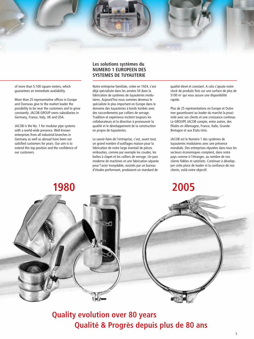
1980 2005
Les solutions systèmes duNUMERO 1 EUROPEEN DES SYSTEMES DE TUYAUTERIE
of more than 5.100 square meters, whichguarantees an immediate availability.
More than 25 representative offices in Europeand Overseas give to the market leader thepossibility to be near the customers and to growconstantly. JACOB GROUP owns subsidiaries inGermany, France, Italy, UK and USA.
JACOB is the No. 1 for modular pipe systemswith a world-wide presence. Well-knownenterprises from all industrial branches inGermany as well as abroad have been oursatisfied customers for years. Our aim is toextend this top position and the confidence ofour customers.
Notre entreprise familiale, créée en 1924, s'estdéjà spécialisée dans les années 50 dans lafabrication de systèmes de tuyauteries modu-laires. Aujourd'hui nous sommes devenus lespécialiste le plus important en Europe dans ledomaine des tuyauteries à bords tombés avecdes raccordements par colliers de serrage.Tradition et expérience incitent toujours lescollaborateurs et la direction à promouvoir laqualité et le développement de la constructionen propre de tuyauteries.
Le savoir-faire de l'entreprise, c'est, avant tout,un grand nombre d'outillages maison pour lafabrication de notre large éventail de piècesembouties, comme par exemple les coudes, lesboîtes à clapet et les colliers de serrage. Un parcmoderne de machines et une fabrication séparéepour l'acier inoxydable, assistés par un bureaud'études performant, produisent un standard de
qualité élevé et constant. A cela s'ajoute notrestock de produits finis sur une surface de plus de5100 m2 qui vous assure une disponibilitérapide.
Plus de 25 représentations en Europe et Outre-mer garantissent au leader du marché la proxi-mité avec ses clients et une croissance continue.Le GROUPE JACOB compte, entre autres, desfiliales en Allemagne, France, Italie, Grande-Bretagne et aux Etats-Unis.
JACOB est le Numéro 1 des systèmes detuyauteries modulaires avec une présencemondiale. Des entreprises réputées dans tous lessecteurs économiques comptent, dans notrepays comme à l'étranger, au nombre de nosclients fidèles et satisfaits. Continuer à dévelop-per cette place de leader et la confiance de nosclients, voilà notre objectif.
Quality evolution over 80 yearsQualité & Progrès depuis plus de 80 ans
5

6
Europas Nr. 1 in Rohrsystemen – weltweit im Einsatz
Europe’s no. 1 for modular pipe systems – with a global presence
Le numéro 1 des systèmes de tuyauteriemodulaire in Europe. Nous sommes présentsdans le monde entier.
1
Profitieren Sie von der Zusammenarbeit mit uns
Take advantagefrom co-operation with us
Profitez d'une coopération avec nous
• JACOB hat das Spannringsystem entwickelt und stehtfür dichte Rohrsysteme mit Spannringverbindung.
• JACOB has developed the pull-ring system and is a synonym for tight pipe systems with pull-ring connections.
• JACOB a développé le système des colliers de serrage et est le spécialistedes systèmes de tuyauteries étanches avec raccordement par collier deserrage.
• JACOB ist Markt- und Innovationsführer – zum Beispiel mit der Innovation QUICK CONNECT® Spannring.
• JACOB is market leader and top in innovations – for example with the innovation QUICK CONNECT® pull-ring.
• JACOB est leader en termes de marché et d'innovation –par exemple avec son collier de serrage innovant QUICK CONNECT®.

7
1
The JACOB GROUP –
• in über 25 Ländern präsent• present in more than 25 countries• présent dans plus de 25 pays
• ORIGINAL JACOB ist Qualitätsmaßstab. Der hohe Anteil an Werkzeugfertigung sichert gleich bleibend präziseProdukte, die problemlose Austauschbarkeit gewährleisten.
• ORIGINAL JACOB is quality standard. The large range of tool production ensures permanently accurate productsand guarantees an exchange without problems.
• D'ORIGINE JACOB – la référence de qualité. La proportion élevée de fabrication d'outils permet d'assurer des produitsde précision constante, garantissant une interchangeabilité sans problème.
• JACOB steht für kürzeste Lieferzeiten aus dem größten Lager gebördelterRohrteile.
• JACOB offers shortest delivery times out of the largest stock of lipped-endpipework.
• JACOB offre des délais de livraison très courts grâce au plus grand stock detuyaux à bord tombé.
8
JACOB ROHRSYSTEME – hoher Fertigungsstandard, schnelle Lieferfähigkeit, ausgereifte Qualität, faire Preise – Original-Qualität nach dem Baukastenprinzip
JACOB PIPE SYSTEMS – high production standard, short delivery time, perfected quality, fair prices –original quality in modular technique
SYSTEMES DE TUYAUTERIES JACOB –grands standards de fabrication, livraisons rapides, qualité au point, prix corrects –la qualité d'origine selon le principe modulaire
1
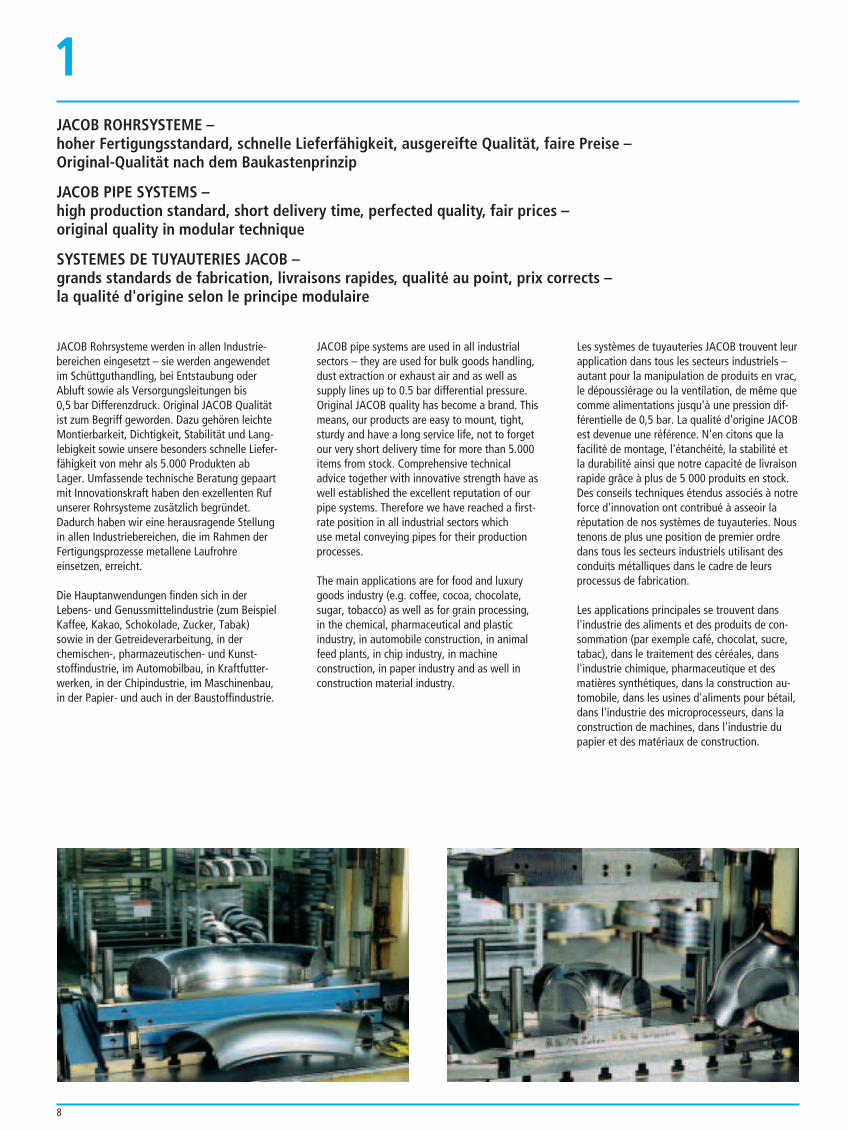
JACOB Rohrsysteme werden in allen Industrie-bereichen eingesetzt – sie werden angewendetim Schüttguthandling, bei Entstaubung oderAbluft sowie als Versorgungsleitungen bis 0,5 bar Differenzdruck. Original JACOB Qualitätist zum Begriff geworden. Dazu gehören leichteMontierbarkeit, Dichtigkeit, Stabilität und Lang-lebigkeit sowie unsere besonders schnelle Liefer-fähigkeit von mehr als 5.000 Produkten abLager. Umfassende technische Beratung gepaartmit Innovationskraft haben den exzellenten Rufunserer Rohrsysteme zusätzlich begründet.Dadurch haben wir eine herausragende Stellungin allen Industriebereichen, die im Rahmen derFertigungsprozesse metallene Laufrohreeinsetzen, erreicht.
Die Hauptanwendungen finden sich in derLebens- und Genussmittelindustrie (zum BeispielKaffee, Kakao, Schokolade, Zucker, Tabak) sowie in der Getreideverarbeitung, in derchemischen-, pharmazeutischen- und Kunst-stoffindustrie, im Automobilbau, in Kraftfutter-werken, in der Chipindustrie, im Maschinenbau,in der Papier- und auch in der Baustoffindustrie.
JACOB pipe systems are used in all industrialsectors – they are used for bulk goods handling,dust extraction or exhaust air and as well assupply lines up to 0.5 bar differential pressure.Original JACOB quality has become a brand. Thismeans, our products are easy to mount, tight,sturdy and have a long service life, not to forgetour very short delivery time for more than 5.000items from stock. Comprehensive technicaladvice together with innovative strength have aswell established the excellent reputation of ourpipe systems. Therefore we have reached a first-rate position in all industrial sectors which use metal conveying pipes for their productionprocesses.
The main applications are for food and luxurygoods industry (e.g. coffee, cocoa, chocolate,sugar, tobacco) as well as for grain processing,in the chemical, pharmaceutical and plasticindustry, in automobile construction, in animalfeed plants, in chip industry, in machine construction, in paper industry and as well inconstruction material industry.
Les systèmes de tuyauteries JACOB trouvent leurapplication dans tous les secteurs industriels –autant pour la manipulation de produits en vrac,le dépoussiérage ou la ventilation, de même quecomme alimentations jusqu'à une pression dif-férentielle de 0,5 bar. La qualité d'origine JACOBest devenue une référence. N'en citons que lafacilité de montage, l'étanchéité, la stabilité et la durabilité ainsi que notre capacité de livraisonrapide grâce à plus de 5 000 produits en stock.Des conseils techniques étendus associés à notreforce d'innovation ont contribué à asseoir laréputation de nos systèmes de tuyauteries. Noustenons de plus une position de premier ordredans tous les secteurs industriels utilisant desconduits métalliques dans le cadre de leursprocessus de fabrication.
Les applications principales se trouvent dansl'industrie des aliments et des produits de con-sommation (par exemple café, chocolat, sucre,tabac), dans le traitement des céréales, dansl'industrie chimique, pharmaceutique et desmatières synthétiques, dans la construction au-tomobile, dans les usines d'aliments pour bétail,dans l'industrie des microprocesseurs, dans laconstruction de machines, dans l'industrie dupapier et des matériaux de construction.
Livraisons rapides
Notre catalogue de produits vous propose plusde 5 000 pièces de différentes versions, quenous tenons à votre disposition dans notre stockde plus de 5 100 mètres carrés. Ainsi, nouspouvons offrir des délais de livraison très courtsà nos clients.
9
1Vorteile im System
Wir bieten Ihnen druckstoßfeste, längsnaht-geschweißte und gebördelte Rohr- und Verteil-systeme nach dem Baukastenprinzip fürSchüttgut, Entstaubung oder Kühlluft/ Abluft(Ø 80-800 mm, Ausführung in Stahl grundiert,verzinkt oder in Edelstahl, 1-3 mm Wandstärke)sowie Sonderfertigung auf Anfrage. Das Baukas-tensystem gewährleistet unseren Kunden denproblemlosen, kompatiblen Austausch und auchdie schnelle Erweiterungsoption.
Advantages in the system
Advantages of the system shock explosion proof,longitudinally welded and flanged pipe anddistributing systems in modules for bulk goods,dust extraction, cooling air / exhaust (Ø 80-800 mm; primed steel, galvanized orstainless steel versions, wall thickness 1-3 mm)as well as special products on request. Themodular system guarantees a compatiblereplacement without problems and gives ourcustomers the option for quick extension.
Les avantages du système
Nous vous proposons des systèmes de tuyauterieet de distribution résistants à la surpression,avec soudures longitudinales et à bords tombés,selon le principe modulaire, pour les produits envrac, le dépoussiérage, l'air de refroidissement/ventilation (Ø 80-800 mm, version acier peint,galvanisé ou acier inoxydable, épaisseur de paroi1-3 mm) ainsi que des fabrications spéciales surdemande. Le système modulaire offre à nosclients le remplacement sans problèmes etcompatible des éléments et leur extension.
Ausgereifte Spitzenprodukte
ORIGINAL JACOB-QUALITÄT ist ein Begriff. Mit unserem Rohrsystem nach dem Baukasten-prinzip – in Verbindung mit unserem bewährtenund innovativen Spannringsystem – setzen wirhöchste Ansprüche an Verarbeitungsqualität undFunktionalität. Beste Fertigungsqualität mitbeispielhafter Dichtigkeit ist für uns Anspruchund zugleich Herausforderung, der wir uns stetsstellen. Unsere Leistungsfähigkeit ist aufKundennutzen und Kundenzufriedenheit ausge-richtet. Das sind die Maximen unserer Kunden-orientierung.
Perfected top quality products
ORIGINAL JACOB QUALITY is a brand. With our modular pipe system – in combinationwith our proven and innovative pull-ring system– we have the highest demands with regard tothe quality of workmanship and function. Bestproduction quality with extraordinary tightnessis our claim as well as challenge, we alwayswant to take up. Our performance is directed toour customers' advantage and satisfaction.These are the main principles of our customerorientation.
Des produits de pointe de grande maturité
La QUALITE D'ORIGINE JACOB est une référen-ce. Avec notre système de tuyauterie modulaire– associé à notre système de serrage innovantqui a fait ses preuves – nous sommes trèsexigeants en termes de qualité de mise enœuvre et de fonctionnalité. Notre ambition maiségalement le défi auquel nous faisons constam-ment face, c'est la meilleure qualité de fabri-cation avec une étanchéité exemplaire. Notreperformance s'oriente à l'utilité pour le client età la satisfaction du client. Voici les principes denotre orientation clientèle.
Schnelle Lieferfähigkeit
In unserem Produktkatalog finden Sie mehr als5.000 Teile in verschiedensten Ausführungen, diewir in unserem Lieferprogramm für Sie auf einemmehr als 5.100 Quadratmeter großem Lagerständig bereithalten. Dadurch bieten wir unserenKunden eine beispielhaft schnelle Lieferfähigkeit.
Short delivery times
In our product catalogue you will find more than5.000 components in different makes out of ourproduct range, which are available for you in awarehouse that is larger than 5.100 squaremetres. Therefore we can offer extraordinaryshort delivery times to our customers.
Faire Preise
Die Kostenstruktur unserer Produkte stellen wirständig auf den Prüfstand. Faire Preise gehörenfür uns zur Erfolgssicherung. Kostenvorteilegeben wir deshalb stets in vollem Umfang anunsere Kunden weiter.
Fair prices
The cost structure of our products is permanentlychecked. For us, fair prices are part of oursuccess. Price advantages are therefore alwayspassed on to our customers.
Des prix corrects
La structure des coûts de nos produits faitconstamment l'objet de réévaluation. Des prixcorrects font pour nous partie de la garantie dusuccès. Pour cette raison, nous faisonsentièrement bénéficier nos clients des avantagesen termes de coût que nous pouvons obtenir.
Zufriedene Kunden sprechen für uns
Am besten Original-Qualität von JACOB ROHRSYSTEME. Sicher – wirtschaftlich –bewährt. Unser Preis-Leistungs-Verhältnisstimmt. Ihr Vertrauen in unsere Produkte und inunsere Leistungsfähigkeit hat uns zur Nr. 1 inEuropa für Rohrsysteme nach dem Baukasten-prinzip gemacht. Mehr Kundennutzen ist unserZiel. Daran arbeiten wir ständig. Wir setzen auflangjährige Partnerschaften durch zufriedeneKunden. Langlebige und gut funktionierendeAnlagen stehen für die JACOB-Erfolgsgeschichte.
Satisfied customers –our best recommendation
The best is original quality by JACOB PIPE SYSTEMS. Safe – economic –proven. Our price – performance relation iscorrect. Your confidence in our products and ourperformance has made us No. 1 in Europe formodular pipe systems. Our aim is to satisfy ourcustomers best. On this we are workingpermanently. We rely on long-lasting partner-ships as a result of satisfied customers. Durablesystems with perfect function are the reason forJACOB's story of success.
Des clients satisfaits sont nos porte-parole
De préférence la qualité d'origine des SYSTEMES DE TUYAUTERIES JACOB. Sûrs –économiques – éprouvés. Avec un bon rapportqualité/prix. Votre confiance accordée à nosproduits et à notre performance a fait de nous le N° 1 des systèmes de tuyauteries modulaires.Nous visons un plus grand profit pour le client etnous y travaillons constamment. Nous misonssur des partenariats à long terme grâce à desclients satisfaits. L'histoire du succès de JACOBrepose sur des installations durables quifonctionnent parfaitement.
10
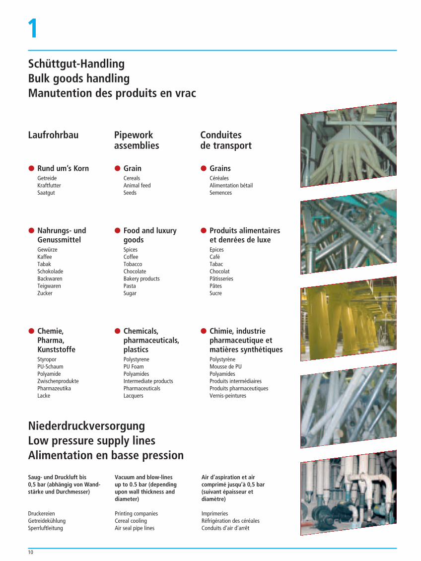
Schüttgut-HandlingBulk goods handlingManutention des produits en vrac
1
Conduitesde transport
$ GrainsCéréalesAlimentation bétailSemences
$ Produits alimentaireset denrées de luxeEpicesCaféTabacChocolatPâtisseriesPâtesSucre
$ Chimie, industriepharmaceutique etmatières synthétiquesPolystyrèneMousse de PUPolyamidesProduits intermédiairesProduits pharmaceutiquesVernis-peintures
Saug- und Druckluft bis 0,5 bar (abhängig von Wand-stärke und Durchmesser)
DruckereienGetreidekühlungSperrluftleitung
Vacuum and blow-linesup to 0.5 bar (dependingupon wall thickness anddiameter)
Printing companiesCereal coolingAir seal pipe lines
Air d’aspiration et aircomprimé jusqu’à 0,5 bar(suivant épaisseur et diamètre)
ImprimeriesRéfrigération des céréalesConduits d’air d’arrêt
Laufrohrbau
$ Rund um’s KornGetreideKraftfutterSaatgut
$ Nahrungs- und GenussmittelGewürzeKaffeeTabakSchokoladeBackwarenTeigwarenZucker
$ Chemie, Pharma, KunststoffeStyroporPU-SchaumPolyamideZwischenproduktePharmazeutikaLacke
Pipeworkassemblies
$ GrainCerealsAnimal feedSeeds
$ Food and luxury goodsSpicesCoffeeTobaccoChocolateBakery productsPastaSugar
$ Chemicals, pharmaceuticals, plasticsPolystyrenePU FoamPolyamidesIntermediate productsPharmaceuticalsLacquers
NiederdruckversorgungLow pressure supply linesAlimentation en basse pression
11
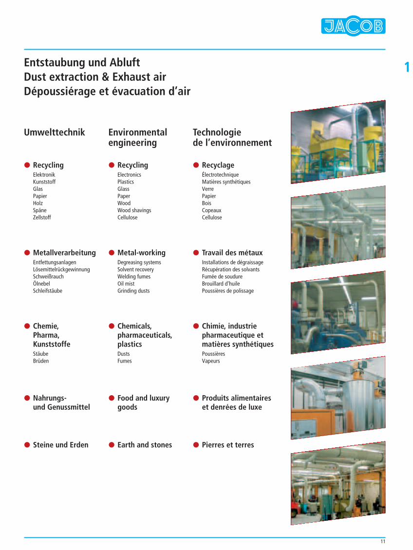
1Entstaubung und AbluftDust extraction & Exhaust airDépoussiérage et évacuation d’air
Technologie de l’environnement
$ RecyclageÉlectrotechniqueMatières synthétiquesVerrePapierBoisCopeauxCellulose
$ Travail des métauxInstallations de dégraissageRécupération des solvantsFumée de soudureBrouillard d’huilePoussières de polissage
$ Chimie, industrie pharmaceutique et matières synthétiquesPoussièresVapeurs
$ Produits alimentaireset denrées de luxe
$ Pierres et terres
Umwelttechnik
$ RecyclingElektronikKunststoffGlasPapierHolzSpäneZellstoff
$ MetallverarbeitungEntfettungsanlagenLösemittelrückgewinnungSchweißrauchÖlnebelSchleifstäube
$ Chemie, Pharma, KunststoffeStäubeBrüden
$ Nahrungs- und Genussmittel
$ Steine und Erden
Environmentalengineering
$ RecyclingElectronicsPlasticsGlassPaperWoodWood shavingsCellulose
$ Metal-workingDegreasing systemsSolvent recoveryWelding fumesOil mistGrinding dusts
$ Chemicals, pharmaceuticals, plasticsDustsFumes
$ Food and luxurygoods
$ Earth and stones
12
1Sonderteilfertigung
Sie brauchen individuelleLösungen – mit uns kein Problem!
Bei besonderen Anwendungsfällen bietet Ihnendas JACOB-Service-Team gern maßgeschneiderteProblemlösungen.
Sie können sich auf die umfassende Erfahrungunserer Techniker verlassen. Planerische undkonzeptionelle Unterstützung gehören für unszum selbstverständlichen technischen Kunden-service.
Profitieren Sie von unserer Fachkompetenz bei der Beratung und speziellen Problemlösungen Ihres individuellen Anlagenbedarfs.
Jederzeit gewährleisten wir die Kompatibilitätunseres gesamten Baukastensystems.Druckstoßfestigkeit, beispielgebende Qualität,Dichtigkeit, schnelle Montage, Wartungsfreund-lichkeit. Dafür stehen wir: Original-Qualität vonJACOB.
Sonderfertigung mit EUROPAS NR. 1 IN ROHRSYSTEMEN. Testen Sie uns!
Special components production
You need individual solutions – no problem with us!
For special applications the JACOB service teamlikes to offer tailor-made solutions.
You can rely on the large experience of ourtechnicians. Support in planning and designbelong, of course, to our technical customerservice.
Take advantage of our competence in consultingand offering you special solutions for yourproblems concerning individual requirements foryour system.
We always guarantee compatibility of our entiremodular system. Surge pressure proof products,exemplary quality, tightness, fast mounting, easymaintenance. For this we excel: Original qualityby JACOB.
Special production with EUROPE's No. 1 IN PIPE SYSTEMS. Test us!
Fabrication de pièces spéciales
Des solutions individuelles –aucun problème pour nous!
L'équipe Service de JACOB vous proposevolontiers des solutions sur mesure pour des casd'application particuliers.
Vous pouvez faire confiance à la grande expéri-ence de nos techniciens. L'aide à la planificationet à la conception font chez nous naturellementpartie du service technique à la clientèle.
Profitez de notre compétence technique lorsd'entretiens de conseil et des solutions spé-cifiques aux problèmes posés par vos instal-lations individuelles.
Nous offrons à tout moment la compatibilité detout notre système modulaire. Résistance à lasurpression, qualité exemplaire, étanchéité,montage rapide, facilité d'entretien. Nous nousen portons garant: la qualité d'origine de JACOB.
Fabrications sur mesure avec le N° 1 desSYSTEMES DE TUYAUTERIES EN EUROPE. Testez-nous!
Bestellnummern Fettdruck = Lagerteile bzw. kurzfristig lieferbar.Bold order numbers = components on stock or short delivery time.Références en gras = pièces sur stock rapidement disponibles.
Zertifiziert
Auf Anfrage erhältlich: Übersicht der Produkte mitSpannringverbindung geprüft auf Druckstoßfestigkeit.
Available on request: Survey of our products withpull-ring connection shock-explosion proof.
Sur demande: Résumé de nos produits avec liaison parcolliers certifiés tenant à la surpression.
Auf den folgenden Seiten sind nicht alle lieferbarenDurchmesser und Materialien aufgeführt. Preise undLieferzeiten auf Anfrage.
The following pages do not list up all availablediameters and materials. Prices and delivery time onrequest.
Les pages ci-après ne listent pas tous les diamètres etmatériaux disponibles. Prix et délais de livraison surdemande.
Alle Rohrteile sind dicht geschweißt, nicht gefalzt oder überlappend gepunktet.
All components are tightly continuously welded, not folded nor overlapping spot welded.
Tous les tuyaux sont soudés de façon étanche,non pas pliés ou pointés par chevauchement.
13
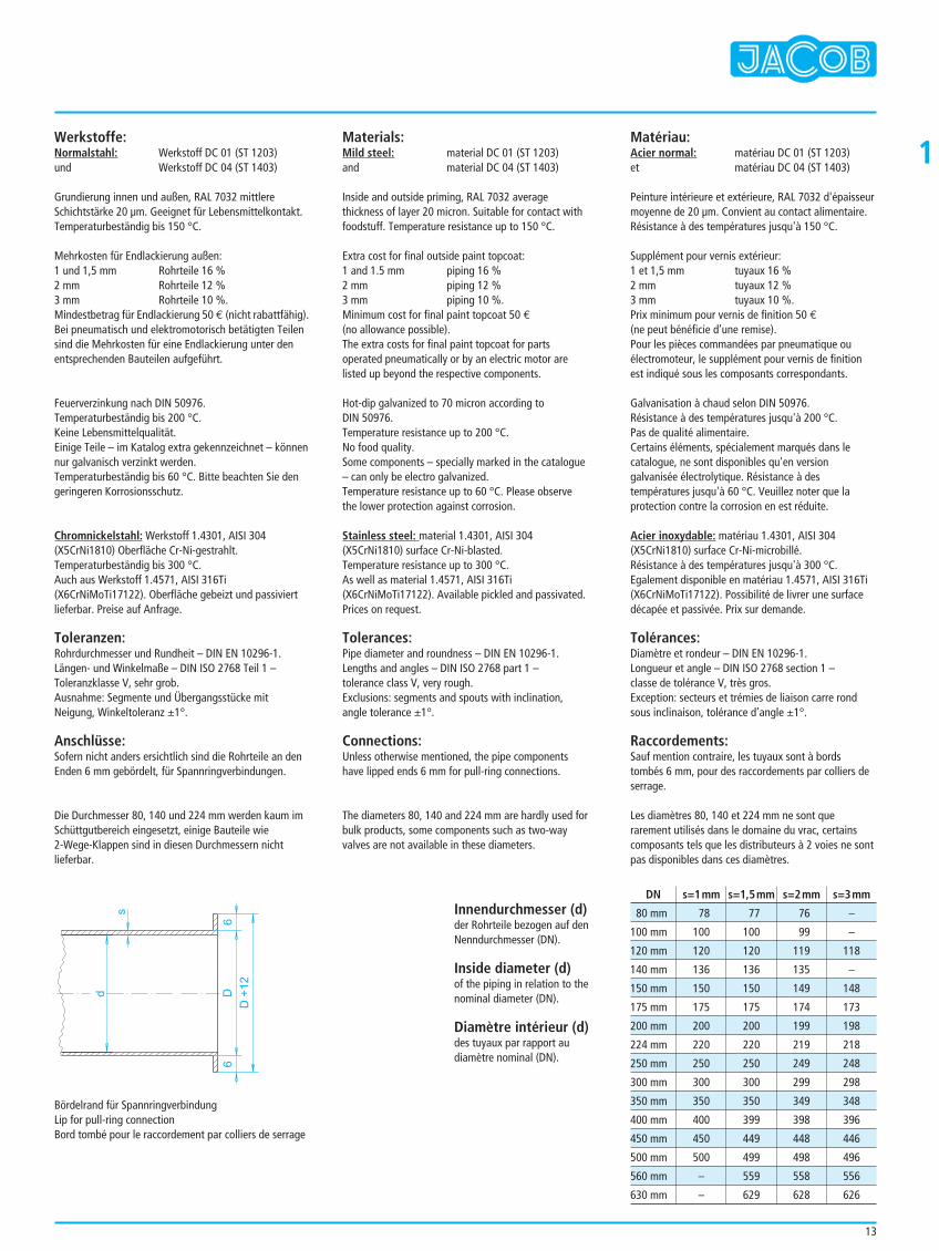
1Werkstoffe:Normalstahl: Werkstoff DC 01 (ST 1203)und Werkstoff DC 04 (ST 1403)
Grundierung innen und außen, RAL 7032 mittlereSchichtstärke 20 µm. Geeignet für Lebensmittelkontakt.Temperaturbeständig bis 150 °C.
Mehrkosten für Endlackierung außen:1 und 1,5 mm Rohrteile 16 %2 mm Rohrteile 12 %3 mm Rohrteile 10 %.Mindestbetrag für Endlackierung 50 € (nicht rabattfähig).Bei pneumatisch und elektromotorisch betätigten Teilensind die Mehrkosten für eine Endlackierung unter denentsprechenden Bauteilen aufgeführt.
Feuerverzinkung nach DIN 50976.Temperaturbeständig bis 200 °C.Keine Lebensmittelqualität.Einige Teile – im Katalog extra gekennzeichnet – könnennur galvanisch verzinkt werden.Temperaturbeständig bis 60 °C. Bitte beachten Sie dengeringeren Korrosionsschutz.
Chromnickelstahl: Werkstoff 1.4301, AISI 304 (X5CrNi1810) Oberfläche Cr-Ni-gestrahlt.Temperaturbeständig bis 300 °C.Auch aus Werkstoff 1.4571, AISI 316Ti (X6CrNiMoTi17122). Oberfläche gebeizt und passiviertlieferbar. Preise auf Anfrage.
Toleranzen:Rohrdurchmesser und Rundheit – DIN EN 10296-1.Längen- und Winkelmaße – DIN ISO 2768 Teil 1 –Toleranzklasse V, sehr grob.Ausnahme: Segmente und Übergangsstücke mitNeigung, Winkeltoleranz ±1°.
Anschlüsse:Sofern nicht anders ersichtlich sind die Rohrteile an denEnden 6 mm gebördelt, für Spannringverbindungen.
Die Durchmesser 80, 140 und 224 mm werden kaum imSchüttgutbereich eingesetzt, einige Bauteile wie 2-Wege-Klappen sind in diesen Durchmessern nichtlieferbar.
Materials:Mild steel: material DC 01 (ST 1203)and material DC 04 (ST 1403)
Inside and outside priming, RAL 7032 averagethickness of layer 20 micron. Suitable for contact withfoodstuff. Temperature resistance up to 150 °C.
Extra cost for final outside paint topcoat:1 and 1.5 mm piping 16 %2 mm piping 12 %3 mm piping 10 %.Minimum cost for final paint topcoat 50 €(no allowance possible).The extra costs for final paint topcoat for partsoperated pneumatically or by an electric motor arelisted up beyond the respective components.
Hot-dip galvanized to 70 micron according toDIN 50976.Temperature resistance up to 200 °C.No food quality.Some components – specially marked in the catalogue– can only be electro galvanized.Temperature resistance up to 60 °C. Please observethe lower protection against corrosion.
Stainless steel: material 1.4301, AISI 304 (X5CrNi1810) surface Cr-Ni-blasted.Temperature resistance up to 300 °C.As well as material 1.4571, AISI 316Ti (X6CrNiMoTi17122). Available pickled and passivated.Prices on request.
Tolerances:Pipe diameter and roundness – DIN EN 10296-1.Lengths and angles – DIN ISO 2768 part 1 – tolerance class V, very rough.Exclusions: segments and spouts with inclination,angle tolerance ±1°.
Connections:Unless otherwise mentioned, the pipe componentshave lipped ends 6 mm for pull-ring connections.
The diameters 80, 140 and 224 mm are hardly used forbulk products, some components such as two-wayvalves are not available in these diameters.
Matériau:Acier normal: matériau DC 01 (ST 1203)et matériau DC 04 (ST 1403)
Peinture intérieure et extérieure, RAL 7032 d'épaisseurmoyenne de 20 µm. Convient au contact alimentaire.Résistance à des températures jusqu'à 150 °C.
Supplément pour vernis extérieur:1 et 1,5 mm tuyaux 16 %2 mm tuyaux 12 %3 mm tuyaux 10 %.Prix minimum pour vernis de finition 50 €(ne peut bénéficie d’une remise).Pour les pièces commandées par pneumatique ouélectromoteur, le supplément pour vernis de finitionest indiqué sous les composants correspondants.
Galvanisation à chaud selon DIN 50976.Résistance à des températures jusqu'à 200 °C.Pas de qualité alimentaire.Certains éléments, spécialement marqués dans lecatalogue, ne sont disponibles qu'en versiongalvanisée électrolytique. Résistance à destempératures jusqu'à 60 °C. Veuillez noter que laprotection contre la corrosion en est réduite.
Acier inoxydable: matériau 1.4301, AISI 304(X5CrNi1810) surface Cr-Ni-microbillé.Résistance à des températures jusqu'à 300 °C.Egalement disponible en matériau 1.4571, AISI 316Ti(X6CrNiMoTi17122). Possibilité de livrer une surfacedécapée et passivée. Prix sur demande.
Tolérances:Diamètre et rondeur – DIN EN 10296-1.Longueur et angle – DIN ISO 2768 section 1 – classe de tolérance V, très gros.Exception: secteurs et trémies de liaison carre rondsous inclinaison, tolérance d’angle ±1°.
Raccordements:Sauf mention contraire, les tuyaux sont à bordstombés 6 mm, pour des raccordements par colliers deserrage.
Les diamètres 80, 140 et 224 mm ne sont querarement utilisés dans le domaine du vrac, certainscomposants tels que les distributeurs à 2 voies ne sontpas disponibles dans ces diamètres.
Bördelrand für SpannringverbindungLip for pull-ring connectionBord tombé pour le raccordement par colliers de serrage
D6
6
d
D+
12
s Innendurchmesser (d)der Rohrteile bezogen auf denNenndurchmesser (DN).
Inside diameter (d)of the piping in relation to thenominal diameter (DN).
Diamètre intérieur (d)des tuyaux par rapport au diamètre nominal (DN).
80 mm 78 77 76 –
100 mm 100 100 99 –
120 mm 120 120 119 118
140 mm 136 136 135 –
150 mm 150 150 149 148
175 mm 175 175 174 173
200 mm 200 200 199 198
224 mm 220 220 219 218
250 mm 250 250 249 248
300 mm 300 300 299 298
350 mm 350 350 349 348
400 mm 400 399 398 396
450 mm 450 449 448 446
500 mm 500 499 498 496
560 mm – 559 558 556
630 mm – 629 628 626
DN s=1mm s=1,5mm s=2mm s=3mm
14
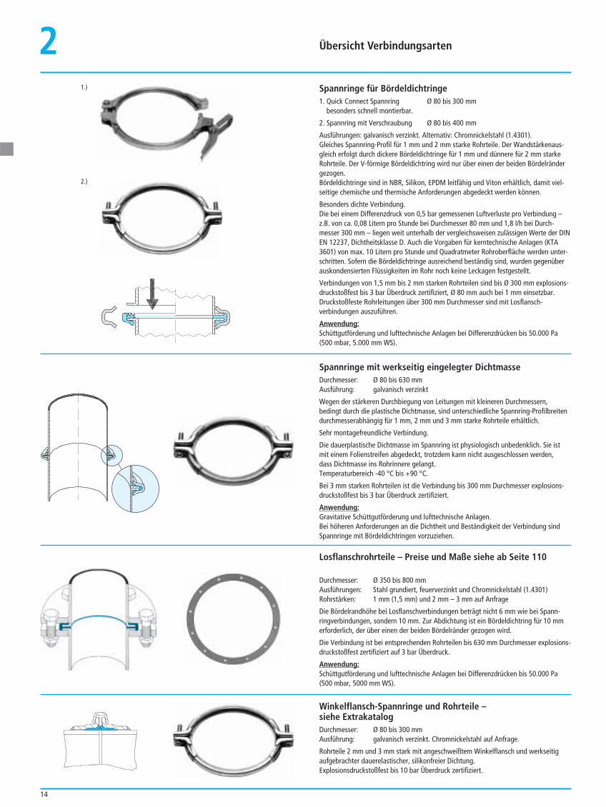
2Spannringe für Bördeldichtringe1. Quick Connect Spannring Ø 80 bis 300 mm
besonders schnell montierbar.
2. Spannring mit Verschraubung Ø 80 bis 400 mm
Ausführungen: galvanisch verzinkt. Alternativ: Chromnickelstahl (1.4301).Gleiches Spannring-Profil für 1 mm und 2 mm starke Rohrteile. Der Wandstärkenaus-gleich erfolgt durch dickere Bördeldichtringe für 1 mm und dünnere für 2 mm starkeRohrteile. Der V-förmige Bördeldichtring wird nur über einen der beiden Bördelrändergezogen.Bördeldichtringe sind in NBR, Silikon, EPDM leitfähig und Viton erhältlich, damit viel-seitige chemische und thermische Anforderungen abgedeckt werden können.
Besonders dichte Verbindung.Die bei einem Differenzdruck von 0,5 bar gemessenen Luftverluste pro Verbindung –z.B. von ca. 0,08 Litern pro Stunde bei Durchmesser 80 mm und 1,8 l/h bei Durch-messer 300 mm – liegen weit unterhalb der vergleichsweisen zulässigen Werte der DINEN 12237, Dichtheitsklasse D. Auch die Vorgaben für kerntechnische Anlagen (KTA3601) von max. 10 Litern pro Stunde und Quadratmeter Rohroberfläche werden unter-schritten. Sofern die Bördeldichtringe ausreichend beständig sind, wurden gegenüberauskondensierten Flüssigkeiten im Rohr noch keine Leckagen festgestellt.
Verbindungen von 1,5 mm bis 2 mm starken Rohrteilen sind bis Ø 300 mm explosions-druckstoßfest bis 3 bar Überdruck zertifiziert, Ø 80 mm auch bei 1 mm einsetzbar.Druckstoßfeste Rohrleitungen über 300 mm Durchmesser sind mit Losflansch-verbindungen auszuführen.
Anwendung:Schüttgutförderung und lufttechnische Anlagen bei Differenzdrücken bis 50.000 Pa(500 mbar, 5.000 mm WS).
Spannringe mit werkseitig eingelegter DichtmasseDurchmesser: Ø 80 bis 630 mmAusführung: galvanisch verzinkt
Wegen der stärkeren Durchbiegung von Leitungen mit kleineren Durchmessern,bedingt durch die plastische Dichtmasse, sind unterschiedliche Spannring-Profilbreitendurchmesserabhängig für 1 mm, 2 mm und 3 mm starke Rohrteile erhältlich.
Sehr montagefreundliche Verbindung.
Die dauerplastische Dichtmasse im Spannring ist physiologisch unbedenklich. Sie istmit einem Folienstreifen abgedeckt, trotzdem kann nicht ausgeschlossen werden, dass Dichtmasse ins Rohrinnere gelangt.Temperaturbereich -40 °C bis +90 °C.
Bei 3 mm starken Rohrteilen ist die Verbindung bis 300 mm Durchmesser explosions-druckstoßfest bis 3 bar Überdruck zertifiziert.
Anwendung:Gravitative Schüttgutförderung und lufttechnische Anlagen.Bei höheren Anforderungen an die Dichtheit und Beständigkeit der Verbindung sindSpannringe mit Bördeldichtringen vorzuziehen.
Losflanschrohrteile – Preise und Maße siehe ab Seite 110
Durchmesser: Ø 350 bis 800 mmAusführungen: Stahl grundiert, feuerverzinkt und Chromnickelstahl (1.4301)Rohrstärken: 1 mm (1,5 mm) und 2 mm – 3 mm auf Anfrage
Die Bördelrandhöhe bei Losflanschverbindungen beträgt nicht 6 mm wie bei Spann-ringverbindungen, sondern 10 mm. Zur Abdichtung ist ein Bördeldichtring für 10 mmerforderlich, der über einen der beiden Bördelränder gezogen wird.
Die Verbindung ist bei entsprechenden Rohrteilen bis 630 mm Durchmesser explosions-druckstoßfest zertifiziert auf 3 bar Überdruck.
Anwendung:Schüttgutförderung und lufttechnische Anlagen bei Differenzdrücken bis 50.000 Pa(500 mbar, 5000 mm WS).
Winkelflansch-Spannringe und Rohrteile –siehe ExtrakatalogDurchmesser: Ø 80 bis 300 mmAusführung: galvanisch verzinkt. Chromnickelstahl auf Anfrage.
Rohrteile 2 mm und 3 mm stark mit angeschweißtem Winkelflansch und werkseitigaufgebrachter dauerelastischer, silikonfreier Dichtung.Explosionsdruckstoßfest bis 10 bar Überdruck zertifiziert.
1.)
2.)
Übersicht Verbindungsarten
15
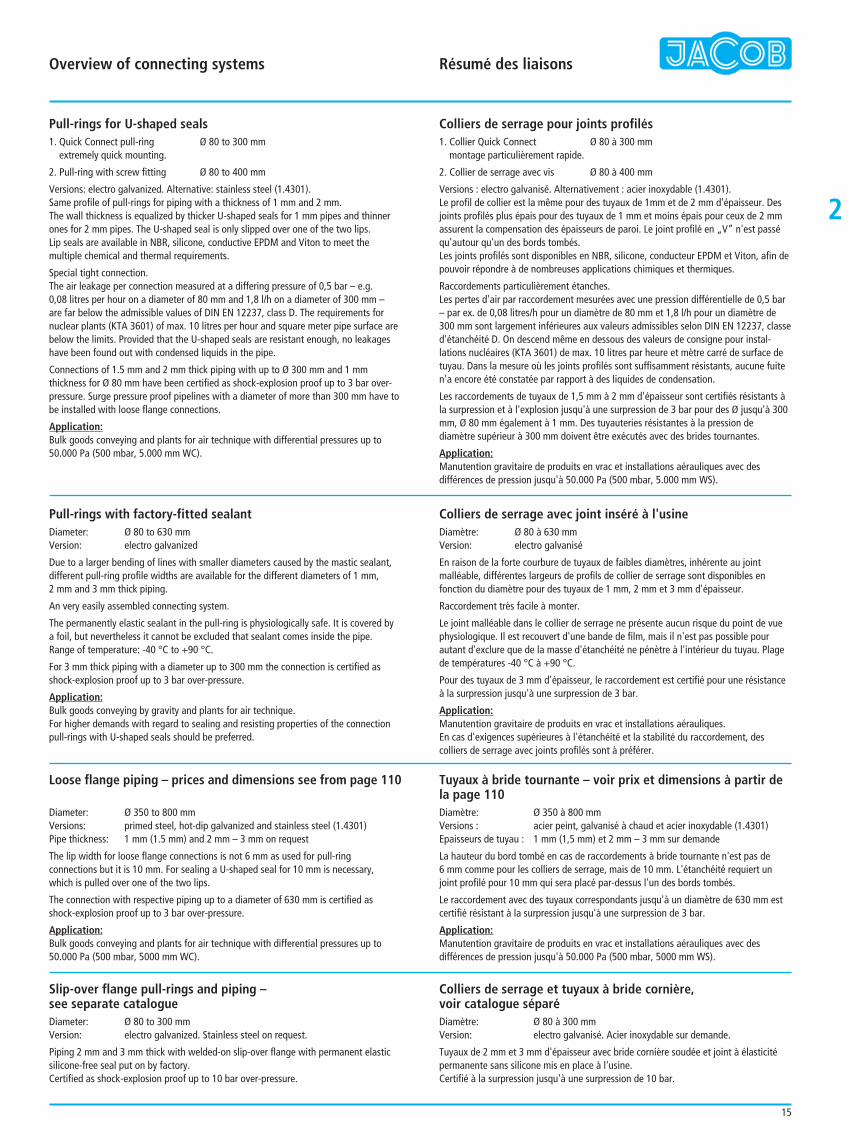
Pull-rings for U-shaped seals1. Quick Connect pull-ring Ø 80 to 300 mm
extremely quick mounting.
2. Pull-ring with screw fitting Ø 80 to 400 mm
Versions: electro galvanized. Alternative: stainless steel (1.4301).Same profile of pull-rings for piping with a thickness of 1 mm and 2 mm. The wall thickness is equalized by thicker U-shaped seals for 1 mm pipes and thinnerones for 2 mm pipes. The U-shaped seal is only slipped over one of the two lips.Lip seals are available in NBR, silicone, conductive EPDM and Viton to meet themultiple chemical and thermal requirements.
Special tight connection.The air leakage per connection measured at a differing pressure of 0,5 bar – e.g. 0,08 litres per hour on a diameter of 80 mm and 1,8 l/h on a diameter of 300 mm – are far below the admissible values of DIN EN 12237, class D. The requirements fornuclear plants (KTA 3601) of max. 10 litres per hour and square meter pipe surface arebelow the limits. Provided that the U-shaped seals are resistant enough, no leakageshave been found out with condensed liquids in the pipe.
Connections of 1.5 mm and 2 mm thick piping with up to Ø 300 mm and 1 mmthickness for Ø 80 mm have been certified as shock-explosion proof up to 3 bar over-pressure. Surge pressure proof pipelines with a diameter of more than 300 mm have tobe installed with loose flange connections.
Application:Bulk goods conveying and plants for air technique with differential pressures up to50.000 Pa (500 mbar, 5.000 mm WC).
Colliers de serrage pour joints profilés1. Collier Quick Connect Ø 80 à 300 mm
montage particulièrement rapide.
2. Collier de serrage avec vis Ø 80 à 400 mm
Versions : electro galvanisé. Alternativement : acier inoxydable (1.4301).Le profil de collier est la même pour des tuyaux de 1mm et de 2 mm d'épaisseur. Desjoints profilés plus épais pour des tuyaux de 1 mm et moins épais pour ceux de 2 mmassurent la compensation des épaisseurs de paroi. Le joint profilé en „V“ n'est passéqu'autour qu'un des bords tombés.Les joints profilés sont disponibles en NBR, silicone, conducteur EPDM et Viton, afin depouvoir répondre à de nombreuses applications chimiques et thermiques.
Raccordements particulièrement étanches.Les pertes d'air par raccordement mesurées avec une pression différentielle de 0,5 bar– par ex. de 0,08 litres/h pour un diamètre de 80 mm et 1,8 l/h pour un diamètre de300 mm sont largement inférieures aux valeurs admissibles selon DIN EN 12237, classed'étanchéité D. On descend même en dessous des valeurs de consigne pour instal-lations nucléaires (KTA 3601) de max. 10 litres par heure et mètre carré de surface detuyau. Dans la mesure où les joints profilés sont suffisamment résistants, aucune fuiten'a encore été constatée par rapport à des liquides de condensation.
Les raccordements de tuyaux de 1,5 mm à 2 mm d'épaisseur sont certifiés résistants àla surpression et à l'explosion jusqu'à une surpression de 3 bar pour des Ø jusqu'à 300mm, Ø 80 mm également à 1 mm. Des tuyauteries résistantes à la pression dediamètre supérieur à 300 mm doivent être exécutés avec des brides tournantes.
Application:Manutention gravitaire de produits en vrac et installations aérauliques avec desdifférences de pression jusqu'à 50.000 Pa (500 mbar, 5.000 mm WS).
Pull-rings with factory-fitted sealantDiameter: Ø 80 to 630 mmVersion: electro galvanized
Due to a larger bending of lines with smaller diameters caused by the mastic sealant,different pull-ring profile widths are available for the different diameters of 1 mm, 2 mm and 3 mm thick piping.
An very easily assembled connecting system.
The permanently elastic sealant in the pull-ring is physiologically safe. It is covered bya foil, but nevertheless it cannot be excluded that sealant comes inside the pipe.Range of temperature: -40 °C to +90 °C.
For 3 mm thick piping with a diameter up to 300 mm the connection is certified asshock-explosion proof up to 3 bar over-pressure.
Application:Bulk goods conveying by gravity and plants for air technique.For higher demands with regard to sealing and resisting properties of the connectionpull-rings with U-shaped seals should be preferred.
Loose flange piping – prices and dimensions see from page 110
Diameter: Ø 350 to 800 mmVersions: primed steel, hot-dip galvanized and stainless steel (1.4301)Pipe thickness: 1 mm (1.5 mm) and 2 mm – 3 mm on request
The lip width for loose flange connections is not 6 mm as used for pull-ringconnections but it is 10 mm. For sealing a U-shaped seal for 10 mm is necessary, which is pulled over one of the two lips.
The connection with respective piping up to a diameter of 630 mm is certified asshock-explosion proof up to 3 bar over-pressure.
Application:Bulk goods conveying and plants for air technique with differential pressures up to50.000 Pa (500 mbar, 5000 mm WC).
Slip-over flange pull-rings and piping – see separate catalogueDiameter: Ø 80 to 300 mmVersion: electro galvanized. Stainless steel on request.
Piping 2 mm and 3 mm thick with welded-on slip-over flange with permanent elasticsilicone-free seal put on by factory. Certified as shock-explosion proof up to 10 bar over-pressure.
Colliers de serrage avec joint inséré à l'usineDiamètre: Ø 80 à 630 mmVersion: electro galvanisé
En raison de la forte courbure de tuyaux de faibles diamètres, inhérente au jointmalléable, différentes largeurs de profils de collier de serrage sont disponibles enfonction du diamètre pour des tuyaux de 1 mm, 2 mm et 3 mm d'épaisseur.
Raccordement très facile à monter.
Le joint malléable dans le collier de serrage ne présente aucun risque du point de vuephysiologique. Il est recouvert d'une bande de film, mais il n'est pas possible pourautant d'exclure que de la masse d'étanchéité ne pénètre à l'intérieur du tuyau. Plagede températures -40 °C à +90 °C.
Pour des tuyaux de 3 mm d'épaisseur, le raccordement est certifié pour une résistanceà la surpression jusqu'à une surpression de 3 bar.
Application:Manutention gravitaire de produits en vrac et installations aérauliques.En cas d'exigences supérieures à l'étanchéité et la stabilité du raccordement, descolliers de serrage avec joints profilés sont à préférer.
Tuyaux à bride tournante – voir prix et dimensions à partir dela page 110Diamètre: Ø 350 à 800 mmVersions : acier peint, galvanisé à chaud et acier inoxydable (1.4301)Epaisseurs de tuyau : 1 mm (1,5 mm) et 2 mm – 3 mm sur demande
La hauteur du bord tombé en cas de raccordements à bride tournante n'est pas de 6 mm comme pour les colliers de serrage, mais de 10 mm. L'étanchéité requiert unjoint profilé pour 10 mm qui sera placé par-dessus l'un des bords tombés.
Le raccordement avec des tuyaux correspondants jusqu'à un diamètre de 630 mm estcertifié résistant à la surpression jusqu'à une surpression de 3 bar.
Application:Manutention gravitaire de produits en vrac et installations aérauliques avec desdifférences de pression jusqu'à 50.000 Pa (500 mbar, 5000 mm WS).
Colliers de serrage et tuyaux à bride cornière, voir catalogue séparéDiamètre: Ø 80 à 300 mmVersion: electro galvanisé. Acier inoxydable sur demande.
Tuyaux de 2 mm et 3 mm d'épaisseur avec bride cornière soudée et joint à élasticitépermanente sans silicone mis en place à l'usine.Certifié à la surpression jusqu'à une surpression de 10 bar.
2
Overview of connecting systems Résumé des liaisons
16
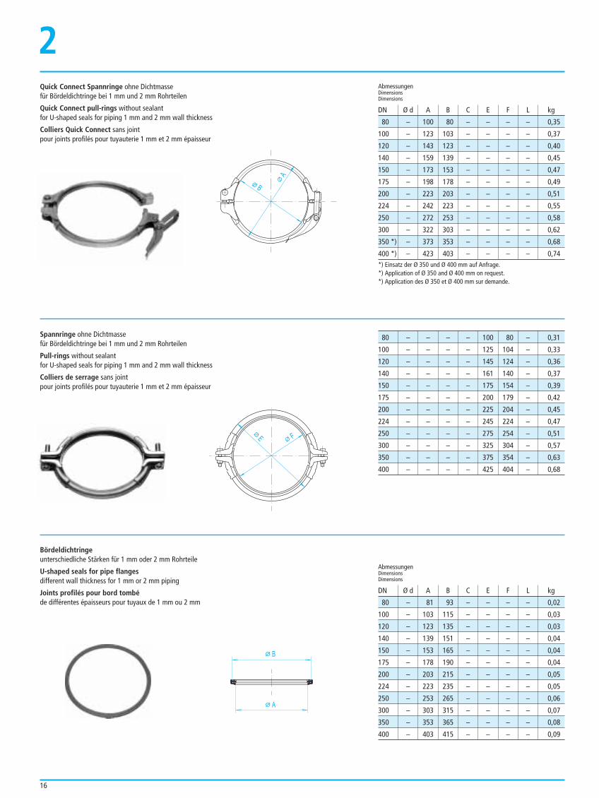
Quick Connect Spannringe ohne Dichtmassefür Bördeldichtringe bei 1 mm und 2 mm Rohrteilen
Quick Connect pull-rings without sealantfor U-shaped seals for piping 1 mm and 2 mm wall thickness
Colliers Quick Connect sans jointpour joints profilés pour tuyauterie 1 mm et 2 mm épaisseur
2
*) Einsatz der Ø 350 und Ø 400 mm auf Anfrage.*) Application of Ø 350 and Ø 400 mm on request.*) Application des Ø 350 et Ø 400 mm sur demande.
Spannringe ohne Dichtmassefür Bördeldichtringe bei 1 mm und 2 mm Rohrteilen
Pull-rings without sealantfor U-shaped seals for piping 1 mm and 2 mm wall thickness
Colliers de serrage sans jointpour joints profilés pour tuyauterie 1 mm et 2 mm épaisseur
Bördeldichtringeunterschiedliche Stärken für 1 mm oder 2 mm Rohrteile
U-shaped seals for pipe flangesdifferent wall thickness for 1 mm or 2 mm piping
Joints profilés pour bord tombéde différentes épaisseurs pour tuyaux de 1 mm ou 2 mm
80 – 100 80 – – – – 0,35
100 – 123 103 – – – – 0,37
120 – 143 123 – – – – 0,40
140 – 159 139 – – – – 0,45
150 – 173 153 – – – – 0,47
175 – 198 178 – – – – 0,49
200 – 223 203 – – – – 0,51
224 – 242 223 – – – – 0,55
250 – 272 253 – – – – 0,58
300 – 322 303 – – – – 0,62
350 *) – 373 353 – – – – 0,68
400 *) – 423 403 – – – – 0,74
AbmessungenDimensionsDimensions
AbmessungenDimensionsDimensions
DN Ø d A B C E F L kg
80 – 81 93 – – – – 0,02
100 – 103 115 – – – – 0,03
120 – 123 135 – – – – 0,03
140 – 139 151 – – – – 0,04
150 – 153 165 – – – – 0,04
175 – 178 190 – – – – 0,04
200 – 203 215 – – – – 0,05
224 – 223 235 – – – – 0,05
250 – 253 265 – – – – 0,06
300 – 303 315 – – – – 0,07
350 – 353 365 – – – – 0,08
400 – 403 415 – – – – 0,09
DN Ø d A B C E F L kg
B
A
FE
B
A
80 – – – – 100 80 – 0,31
100 – – – – 125 104 – 0,33
120 – – – – 145 124 – 0,36
140 – – – – 161 140 – 0,37
150 – – – – 175 154 – 0,39
175 – – – – 200 179 – 0,42
200 – – – – 225 204 – 0,45
224 – – – – 245 224 – 0,47
250 – – – – 275 254 – 0,51
300 – – – – 325 304 – 0,57
350 – – – – 375 354 – 0,63
400 – – – – 425 404 – 0,68
17
2
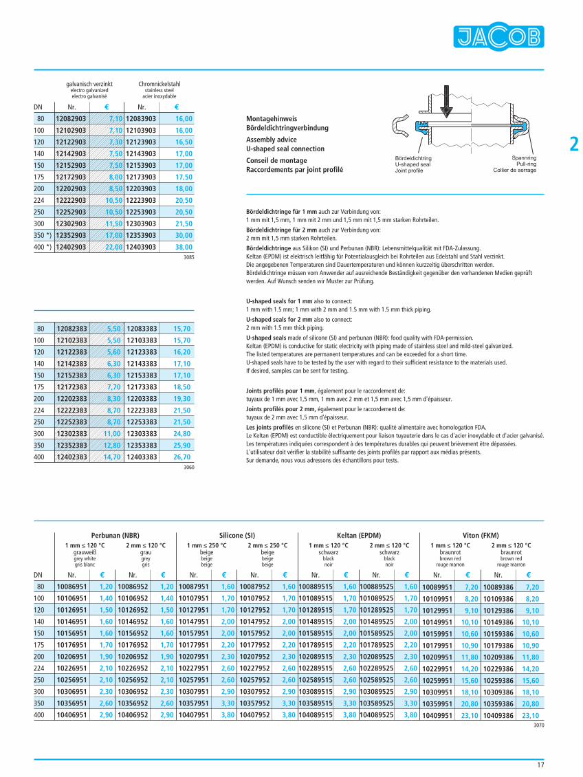
Bördeldichtringe für 1 mm auch zur Verbindung von:1 mm mit 1,5 mm, 1 mm mit 2 mm und 1,5 mm mit 1,5 mm starken Rohrteilen.
Bördeldichtringe für 2 mm auch zur Verbindung von:2 mm mit 1,5 mm starken Rohrteilen.
Bördeldichtringe aus Silikon (SI) und Perbunan (NBR): Lebensmittelqualität mit FDA-Zulassung. Keltan (EPDM) ist elektrisch leitfähig für Potentialausgleich bei Rohrteilen aus Edelstahl und Stahl verzinkt.Die angegebenen Temperaturen sind Dauertemperaturen und können kurzzeitig überschritten werden. Bördeldichtringe müssen vom Anwender auf ausreichende Beständigkeit gegenüber den vorhandenen Medien geprüftwerden. Auf Wunsch senden wir Muster zur Prüfung.
U-shaped seals for 1 mm also to connect:1 mm with 1.5 mm; 1 mm with 2 mm and 1.5 mm with 1.5 mm thick piping.
U-shaped seals for 2 mm also to connect:2 mm with 1.5 mm thick piping.
U-shaped seals made of silicone (SI) and perbunan (NBR): food quality with FDA-permission. Keltan (EPDM) is conductive for static electricity with piping made of stainless steel and mild-steel galvanized.The listed temperatures are permanent temperatures and can be exceeded for a short time.U-shaped seals have to be tested by the user with regard to their sufficient resistance to the materials used.If desired, samples can be sent for testing.
Joints profilés pour 1 mm, également pour le raccordement de:tuyaux de 1 mm avec 1,5 mm, 1 mm avec 2 mm et 1,5 mm avec 1,5 mm d'épaisseur.
Joints profilés pour 2 mm, également pour le raccordement de:tuyaux de 2 mm avec 1,5 mm d'épaisseur.
Les joints profilés en silicone (SI) et Perbunan (NBR): qualité alimentaire avec homologation FDA. Le Keltan (EPDM) est conductible électriquement pour liaison tuyauterie dans le cas d'acier inoxydable et d'acier galvanisé.Les températures indiquées correspondent à des températures durables qui peuvent brièvement être dépassées.L'utilisateur doit vérifier la stabilité suffisante des joints profilés par rapport aux médias présents.Sur demande, nous vous adressons des échantillons pour tests.
MontagehinweisBördeldichtringverbindung
Assembly adviceU-shaped seal connection
Conseil de montageRaccordements par joint profilé
galvanisch verzinkt Chromnickelstahlelectro galvanized stainless steelelectro galvanisé acier inoxydable
Nr. € Nr. €DN
3085
3060
80
100
120
140
150
175
200
224
250
300
350 *)
400 *)
12083903 16,00
12103903 16,00
12123903 16,50
12143903 17,00
12153903 17,00
12173903 17,50
12203903 18,00
12223903 20,50
12253903 20,50
12303903 21,50
12353903 30,00
12403903 38,00
80
100
120
140
150
175
200
224
250
300
350
400
12083383 15,70
12103383 15,70
12123383 16,20
12143383 17,10
12153383 17,10
12173383 18,50
12203383 19,30
12223383 21,50
12253383 21,50
12303383 24,80
12353383 25,90
12403383 26,70
BördeldichtringU-shaped sealJoint profile
SpannringPull-ring
Collier de serrage
10086951 1,20
10106951 1,40
10126951 1,50
10146951 1,60
10156951 1,60
10176951 1,70
10206951 1,90
10226951 2,10
10256951 2,10
10306951 2,30
10356951 2,60
10406951 2,90
10086952 1,20
10106952 1,40
10126952 1,50
10146952 1,60
10156952 1,60
10176952 1,70
10206952 1,90
10226952 2,10
10256952 2,10
10306952 2,30
10356952 2,60
10406952 2,90
10087951 1,60
10107951 1,70
10127951 1,70
10147951 2,00
10157951 2,00
10177951 2,20
10207951 2,30
10227951 2,60
10257951 2,60
10307951 2,90
10357951 3,30
10407951 3,80
10087952 1,60
10107952 1,70
10127952 1,70
10147952 2,00
10157952 2,00
10177952 2,20
10207952 2,30
10227952 2,60
10257952 2,60
10307952 2,90
10357952 3,30
10407952 3,80
100889515 1,60
101089515 1,70
101289515 1,70
101489515 2,00
101589515 2,00
101789515 2,20
102089515 2,30
102289515 2,60
102589515 2,60
103089515 2,90
103589515 3,30
104089515 3,80
100889525 1,60
101089525 1,70
101289525 1,70
101489525 2,00
101589525 2,00
101789525 2,20
102089525 2,30
102289525 2,60
102589525 2,60
103089525 2,90
103589525 3,30
104089525 3,80
10089951 7,20
10109951 8,20
10129951 9,10
10149951 10,10
10159951 10,60
10179951 10,90
10209951 11,80
10229951 14,20
10259951 15,60
10309951 18,10
10359951 20,80
10409951 23,10
10089386 7,20
10109386 8,20
10129386 9,10
10149386 10,10
10159386 10,60
10179386 10,90
10209386 11,80
10229386 14,20
10259386 15,60
10309386 18,10
10359386 20,80
10409386 23,10
DN
80
100
120
140
150
175
200
224
250
300
350
4003070
1 mm ≤ 120 °Cgrauweißgrey whitegris blanc
Perbunan (NBR) Silicone (SI) Keltan (EPDM) Viton (FKM)2 mm ≤ 120 °C
graugreygris
1 mm ≤ 250 °Cbeigebeigebeige
2 mm ≤ 250 °Cbeigebeigebeige
1 mm ≤ 120 °Cschwarz
blacknoir
2 mm ≤ 120 °Cschwarz
blacknoir
1 mm ≤ 120 °Cbraunrotbrown red
rouge marron
2 mm ≤ 120 °Cbraunrotbrown red
rouge marron
Nr. € Nr. € Nr. € Nr. € Nr. € Nr. € Nr. € Nr. €
12082903 7,10
12102903 7,10
12122903 7,30
12142903 7,50
12152903 7,50
12172903 8,00
12202903 8,50
12222903 10,50
12252903 10,50
12302903 11,50
12352903 17,00
12402903 22,00
12082383 5,50
12102383 5,50
12122383 5,60
12142383 6,30
12152383 6,30
12172383 7,70
12202383 8,30
12222383 8,70
12252383 8,70
12302383 11,00
12352383 12,80
12402383 14,70
18
Spannringe mit Dichtmasse
Pull-rings with sealant
Colliers de serrage avec joint
2
Spannringe 1-teilig mit Dichtmasse
Pull-rings one-part with sealant
Colliers de serrage mono-bloc avec joint
Sechskant-Schraubendreher zur Spannringmontage
Hexagon cap screw-driver to mount pull-rings
Tournevis hexagonal pour le montage des colliers de serrage
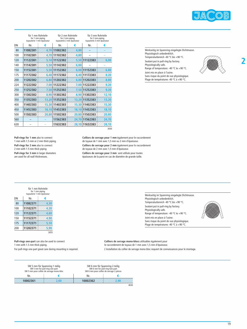
Spannringe für 1 mm auch zur Verbindung von1 mm mit 1,5 mm oder 2 mm starken Rohrteilen.
Spannringe für 2 mm auch zur Verbindung von2 mm mit 1,5 mm starken Rohrteilen.
Spannringe für 3 mm werden in größerenDurchmessern für alle Wandstärken verwendet.
Spannringe 1-teilig auch einsetzbar zur Verbindungvon 1 mm mit 1,5 mm starken Rohrteilen.
Beim Spannring 1-teilig sind Montagekenntnisse erforderlich.
BA
C E
F G
A B
für 1 mmfor
pour
für 2 mmfor
pour
für 3 mmfor
pour
80 – 99 80 100 80 – – 0,23
100 – 121 102 123 103 – – 0,26
120 – 141 122 143 123 145 124 0,28
140 – 157 138 159 139 – – 0,30
150 – 171 152 173 153 175 154 0,33
175 – – – 198 178 200 179 0,34
200 – – – 223 203 225 204 0,38
224 – – – 243 223 243 223 0,40
250 – – – 275 254 275 254 0,42
300 – – – 325 304 325 304 0,50
350 – – – – – 375 354 0,68
400 – – – – – 423 402 0,75
450 – – – – – 473 452 0,81
500 – – – – – 523 502 0,88
560 – – – – – 583 562 0,95
630 – – – – – 653 632 1,05
Abmessungen Alle Ausführungen galvanisch verzinktDimensions All versions electro galvanizedDimensions Toutes versions galvanisées
DN Ø d A B C E F G kg
80 – 97 80 – – – – 0,04
100 – 119 102 – – – – 0,05
120 – 139 122 – – – – 0,06
150 – 169 152 – – – – 0,07
175 – 194 177 – – – – 0,08
200 – 219 202 – – – – 0,09
Abmessungen Ausführung galvanisch verzinktDimensions Version electro galvanizedDimensions Version galvanisée
DN Ø d A B C E F G kg
galvanisch verzinktelectro galvanizedelectro galvanisé
für 1 mmfor
pour
SW
19
2
Pull-rings for 1 mm also to connect1 mm with 1.5 mm or 2 mm thick piping.
Pull-rings for 2 mm also to connect2 mm with 1.5 mm thick piping
Pull-rings for 3 mm in larger diametersare used for all wall thicknesses.
Pull-rings one-part can also be used to connect 1 mm with 1.5 mm thick piping.
For pull-rings one-part great care during mounting is required.
Colliers de serrage pour 1 mm également pour le raccordementde tuyaux de 1 mm avec 1,5 mm ou 2 mm d'épaisseur.
Colliers de serrage pour 2 mm également pour le raccordementde tuyaux de 2 mm avec 1,5 mm d'épaisseur.
Colliers de serrage pour 3 mm sont utilisés pour toutesépaisseurs de la paroi en cas de diamètre de grande taille.
Colliers de serrage mono-blocs utilisables également pourle raccordement de tuyaux de 1 mm avec 1,5 mm d'épaisseur.
L'installation du collier de serrage mono-bloc requiert de connaissances pour le montage.
für 1 mm Rohrteilefor 1 mm piping
tuyauterie 1 mm épaisseur
für 2 mm Rohrteilefor 2 mm piping
tuyauterie 2 mm épaisseur
für 3 mm Rohrteilefor 3 mm piping
tuyauterie 3 mm épaisseur
Nr. € Nr. € Nr. €DN
3050
3055
80
100
120
140
150
175
200
224
250
300
350
400
450
500
560
630
für 1 mm Rohrteilefor 1 mm piping
tuyauterie 1 mm épaisseur
Nr. €DN
80
100
120
150
175
200
4030
SW 5 mm für Spannring 1-teiligSW 5 mm for pull-ring one-part
SW 5 mm pour collier de serrage mono-bloc
SW 6 mm für Spannring 2-teiligSW 6 mm for pull-ring two-part
SW 6 mm pour collier de serrage 2 pièces
Nr. € Nr. €
Werkseitig im Spannring eingelegte Dichtmasse.Physiologisch unbedenklich.Temperaturbereich -40 °C bis +90 °C.
Sealant put in pull-ring by factory.Physiologically safe.Range of temperature: -40 °C to +90 °C.
Joint mis en place à l'usine.Sans risque du point de vue physiologique.Plage de températures -40 °C à +90 °C.
Werkseitig im Spannring eingelegte Dichtmasse.Physiologisch unbedenklich. Temperaturbereich -40 °C bis +90 °C.
Sealant put in pull-ring by factory. Physiologically safe.Range of temperature: -40 °C to +90 °C.
Joint mis en place à l'usine. Sans risque du point de vue physiologique.Plage de températures -40 °C à +90 °C.
11082381 4,70
11102381 4,70
11122381 5,10
11142381 5,50
11152381 5,50
11172382 6,40
11202382 6,80
11222382 7,00
11252382 7,50
11302382 8,90
11352383 13,20
11402383 15,30
11452383 18,10
11502383 20,80
– –
– –
11082382 4,80
11102382 4,80
11122382 5,50
11142382 6,00
11152382 6,00
11172382 6,40
11202382 6,80
11222382 7,00
11252382 7,50
11302382 8,90
11352383 13,20
11402383 15,30
11452383 18,10
11502383 20,80
11562383 24,70
11632383 28,10
– –
– –
11122383 6,00
– –
11152383 6,80
11172383 8,20
11202383 8,80
11222383 9,20
11252383 9,20
11302383 12,10
11352383 13,20
11402383 15,30
11452383 18,10
11502383 20,80
11562383 24,70
11632383 28,10
11082371 4,30
11102371 4,30
11122371 4,60
11152371 4,90
11172371 5,10
11202371 5,90
10002361 2,60 10002362 2,90
20
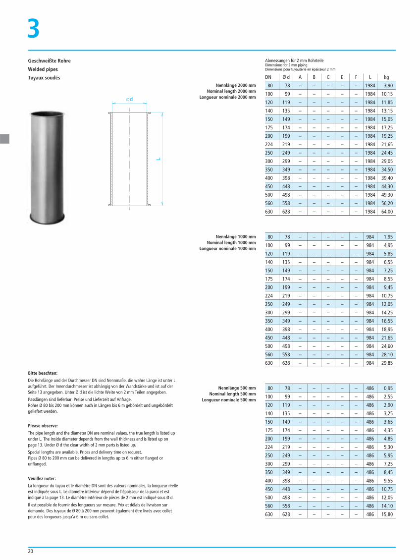
80 78 – – – – – 1984 3,90
100 99 – – – – – 1984 10,15
120 119 – – – – – 1984 11,85
140 135 – – – – – 1984 13,15
150 149 – – – – – 1984 15,05
175 174 – – – – – 1984 17,25
200 199 – – – – – 1984 19,25
224 219 – – – – – 1984 21,65
250 249 – – – – – 1984 24,45
300 299 – – – – – 1984 29,05
350 349 – – – – – 1984 34,50
400 398 – – – – – 1984 39,40
450 448 – – – – – 1984 44,30
500 498 – – – – – 1984 49,30
560 558 – – – – – 1984 56,20
630 628 – – – – – 1984 64,00
Abmessungen für 2 mm RohrteileDimensions for 2 mm pipingDimensions pour tuyauterie en épaisseur 2 mm
DN Ø d A B C E F L kg
Nennlänge 2000 mmNominal length 2000 mm
Longueur nominale 2000 mm
Nennlänge 1000 mmNominal length 1000 mm
Longueur nominale 1000 mm
Nennlänge 500 mmNominal length 500 mm
Longueur nominale 500 mm
80 78 – – – – – 984 1,95
100 99 – – – – – 984 4,95
120 119 – – – – – 984 5,85
140 135 – – – – – 984 6,55
150 149 – – – – – 984 7,25
175 174 – – – – – 984 8,55
200 199 – – – – – 984 9,45
224 219 – – – – – 984 10,75
250 249 – – – – – 984 12,05
300 299 – – – – – 984 14,25
350 349 – – – – – 984 16,55
400 398 – – – – – 984 18,95
450 448 – – – – – 984 21,65
500 498 – – – – – 984 24,60
560 558 – – – – – 984 28,10
630 628 – – – – – 984 29,85
80 78 – – – – – 486 0,95
100 99 – – – – – 486 2,55
120 119 – – – – – 486 2,90
140 135 – – – – – 486 3,25
150 149 – – – – – 486 3,65
175 174 – – – – – 486 4,35
200 199 – – – – – 486 4,85
224 219 – – – – – 486 5,30
250 249 – – – – – 486 5,95
300 299 – – – – – 486 7,25
350 349 – – – – – 486 8,45
400 398 – – – – – 486 9,55
450 448 – – – – – 486 10,75
500 498 – – – – – 486 12,05
560 558 – – – – – 486 14,10
630 628 – – – – – 486 15,80
d
L
Geschweißte Rohre
Welded pipes
Tuyaux soudés
3
Bitte beachten:
Die Rohrlänge und der Durchmesser DN sind Nennmaße, die wahre Länge ist unter Laufgeführt. Der Innendurchmesser ist abhängig von der Wandstärke und ist auf derSeite 13 angegeben. Unter Ø d ist die lichte Weite von 2 mm Teilen angegeben.
Passlängen sind lieferbar. Preise und Lieferzeit auf Anfrage.Rohre Ø 80 bis 200 mm können auch in Längen bis 6 m gebördelt und ungebördeltgeliefert werden.
Please observe:
The pipe length and the diameter DN are nominal values, the true length is listed upunder L. The inside diameter depends from the wall thickness and is listed up on page 13. Under Ø d the clear width of 2 mm parts is listed up.
Special lengths are available. Prices and delivery time on request.Pipes Ø 80 to 200 mm can be delivered in lengths up to 6 m either flanged orunflanged.
Veuillez noter:
La longueur du tuyau et le diamètre DN sont des valeurs nominales, la longueur réelleest indiquée sous L. Le diamètre intérieur dépend de l'épaisseur de la paroi et estindiqué à la page 13. Le diamètre intérieur de pièces de 2 mm est indiqué sous Ø d.
Il est possible de fournir des longueurs sur mesure. Prix et délais de livraison surdemande. Des tuyaux de Ø 80 à 200 mm peuvent également être livrés avec colletpour des longueurs jusqu'à 6 m ou sans collet.
21
3
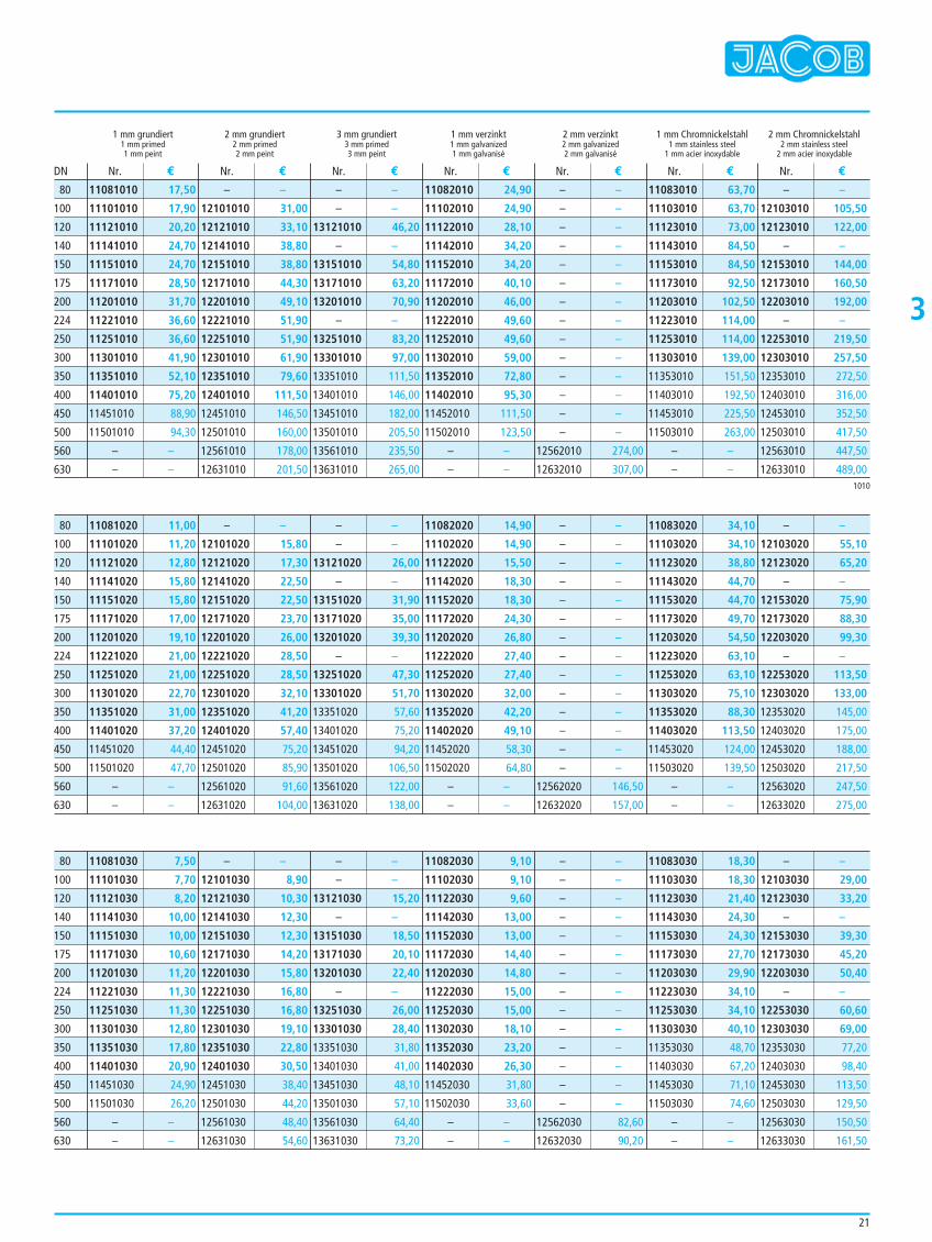
1 mm grundiert 2 mm grundiert 3 mm grundiert 1 mm verzinkt 2 mm verzinkt 1 mm Chromnickelstahl 2 mm Chromnickelstahl1 mm primed 2 mm primed 3 mm primed 1 mm galvanized 2 mm galvanized 1 mm stainless steel 2 mm stainless steel1 mm peint 2 mm peint 3 mm peint 1 mm galvanisé 2 mm galvanisé 1 mm acier inoxydable 2 mm acier inoxydable
11081010 17,50
11101010 17,90
11121010 20,20
11141010 24,70
11151010 24,70
11171010 28,50
11201010 31,70
11221010 36,60
11251010 36,60
11301010 41,90
11351010 52,10
11401010 75,20
11451010 88,90
11501010 94,30
– –
– –
– –
12101010 31,00
12121010 33,10
12141010 38,80
12151010 38,80
12171010 44,30
12201010 49,10
12221010 51,90
12251010 51,90
12301010 61,90
12351010 79,60
12401010 111,50
12451010 146,50
12501010 160,00
12561010 178,00
12631010 201,50
– –
– –
13121010 46,20
– –
13151010 54,80
13171010 63,20
13201010 70,90
– –
13251010 83,20
13301010 97,00
13351010 111,50
13401010 146,00
13451010 182,00
13501010 205,50
13561010 235,50
13631010 265,00
11082010 24,90
11102010 24,90
11122010 28,10
11142010 34,20
11152010 34,20
11172010 40,10
11202010 46,00
11222010 49,60
11252010 49,60
11302010 59,00
11352010 72,80
11402010 95,30
11452010 111,50
11502010 123,50
– –
– –
– –
– –
– –
– –
– –
– –
– –
– –
– –
– –
– –
– –
– –
– –
12562010 274,00
12632010 307,00
11083010 63,70
11103010 63,70
11123010 73,00
11143010 84,50
11153010 84,50
11173010 92,50
11203010 102,50
11223010 114,00
11253010 114,00
11303010 139,00
11353010 151,50
11403010 192,50
11453010 225,50
11503010 263,00
– –
– –
– –
12103010 105,50
12123010 122,00
– –
12153010 144,00
12173010 160,50
12203010 192,00
– –
12253010 219,50
12303010 257,50
12353010 272,50
12403010 316,00
12453010 352,50
12503010 417,50
12563010 447,50
12633010 489,00
Nr. € Nr. € Nr. € Nr. € Nr. € Nr. € Nr. €DN
1010
80
100
120
140
150
175
200
224
250
300
350
400
450
500
560
630
11081020 11,00
11101020 11,20
11121020 12,80
11141020 15,80
11151020 15,80
11171020 17,00
11201020 19,10
11221020 21,00
11251020 21,00
11301020 22,70
11351020 31,00
11401020 37,20
11451020 44,40
11501020 47,70
– –
– –
– –
12101020 15,80
12121020 17,30
12141020 22,50
12151020 22,50
12171020 23,70
12201020 26,00
12221020 28,50
12251020 28,50
12301020 32,10
12351020 41,20
12401020 57,40
12451020 75,20
12501020 85,90
12561020 91,60
12631020 104,00
– –
– –
13121020 26,00
– –
13151020 31,90
13171020 35,00
13201020 39,30
– –
13251020 47,30
13301020 51,70
13351020 57,60
13401020 75,20
13451020 94,20
13501020 106,50
13561020 122,00
13631020 138,00
11082020 14,90
11102020 14,90
11122020 15,50
11142020 18,30
11152020 18,30
11172020 24,30
11202020 26,80
11222020 27,40
11252020 27,40
11302020 32,00
11352020 42,20
11402020 49,10
11452020 58,30
11502020 64,80
– –
– –
– –
– –
– –
– –
– –
– –
– –
– –
– –
– –
– –
– –
– –
– –
12562020 146,50
12632020 157,00
11083020 34,10
11103020 34,10
11123020 38,80
11143020 44,70
11153020 44,70
11173020 49,70
11203020 54,50
11223020 63,10
11253020 63,10
11303020 75,10
11353020 88,30
11403020 113,50
11453020 124,00
11503020 139,50
– –
– –
– –
12103020 55,10
12123020 65,20
– –
12153020 75,90
12173020 88,30
12203020 99,30
– –
12253020 113,50
12303020 133,00
12353020 145,00
12403020 175,00
12453020 188,00
12503020 217,50
12563020 247,50
12633020 275,00
80
100
120
140
150
175
200
224
250
300
350
400
450
500
560
630
11081030 7,50
11101030 7,70
11121030 8,20
11141030 10,00
11151030 10,00
11171030 10,60
11201030 11,20
11221030 11,30
11251030 11,30
11301030 12,80
11351030 17,80
11401030 20,90
11451030 24,90
11501030 26,20
– –
– –
– –
12101030 8,90
12121030 10,30
12141030 12,30
12151030 12,30
12171030 14,20
12201030 15,80
12221030 16,80
12251030 16,80
12301030 19,10
12351030 22,80
12401030 30,50
12451030 38,40
12501030 44,20
12561030 48,40
12631030 54,60
– –
– –
13121030 15,20
– –
13151030 18,50
13171030 20,10
13201030 22,40
– –
13251030 26,00
13301030 28,40
13351030 31,80
13401030 41,00
13451030 48,10
13501030 57,10
13561030 64,40
13631030 73,20
11082030 9,10
11102030 9,10
11122030 9,60
11142030 13,00
11152030 13,00
11172030 14,40
11202030 14,80
11222030 15,00
11252030 15,00
11302030 18,10
11352030 23,20
11402030 26,30
11452030 31,80
11502030 33,60
– –
– –
– –
– –
– –
– –
– –
– –
– –
– –
– –
– –
– –
– –
– –
– –
12562030 82,60
12632030 90,20
11083030 18,30
11103030 18,30
11123030 21,40
11143030 24,30
11153030 24,30
11173030 27,70
11203030 29,90
11223030 34,10
11253030 34,10
11303030 40,10
11353030 48,70
11403030 67,20
11453030 71,10
11503030 74,60
– –
– –
– –
12103030 29,00
12123030 33,20
– –
12153030 39,30
12173030 45,20
12203030 50,40
– –
12253030 60,60
12303030 69,00
12353030 77,20
12403030 98,40
12453030 113,50
12503030 129,50
12563030 150,50
12633030 161,50
80
100
120
140
150
175
200
224
250
300
350
400
450
500
560
630
3
22
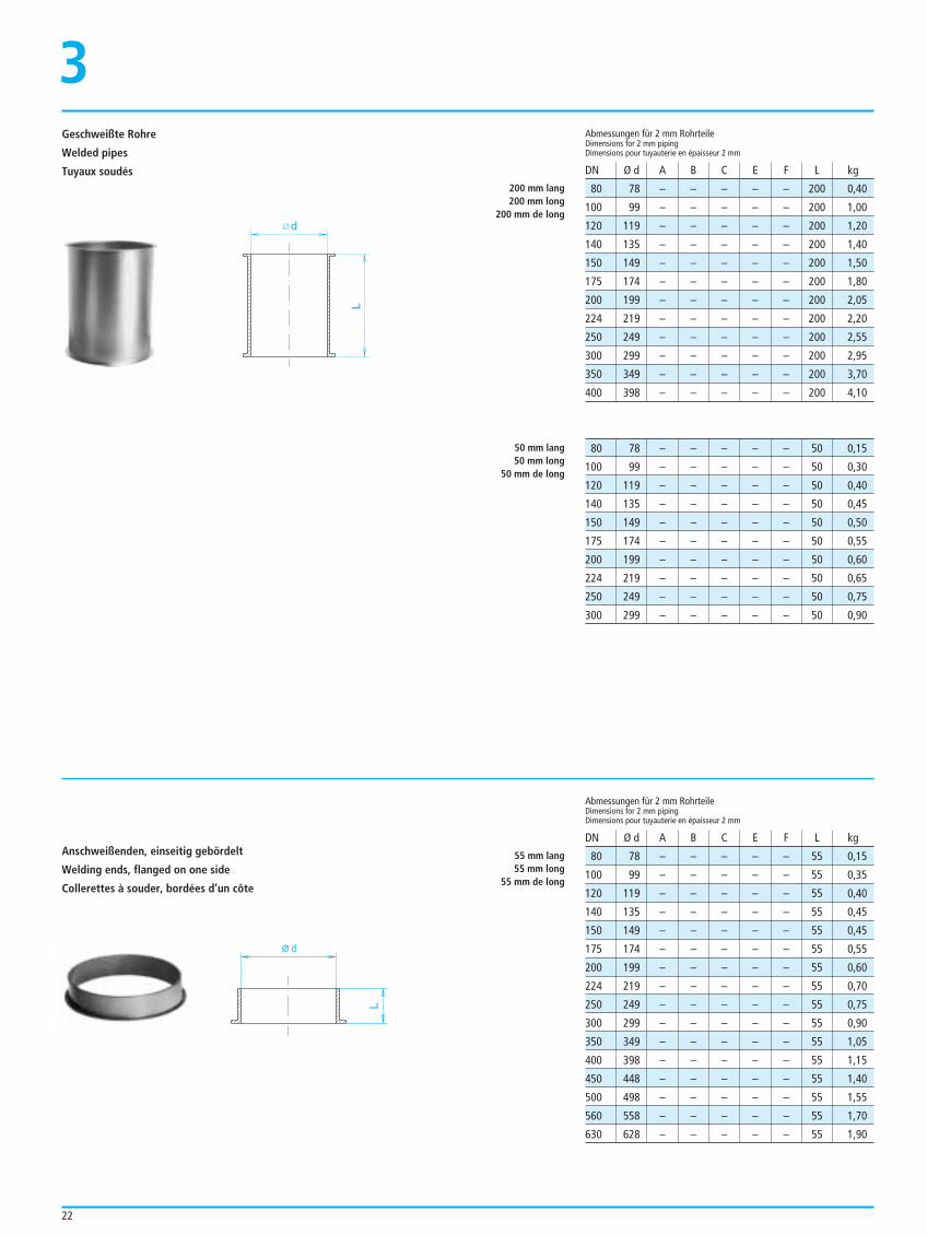
80 78 – – – – – 200 0,40
100 99 – – – – – 200 1,00
120 119 – – – – – 200 1,20
140 135 – – – – – 200 1,40
150 149 – – – – – 200 1,50
175 174 – – – – – 200 1,80
200 199 – – – – – 200 2,05
224 219 – – – – – 200 2,20
250 249 – – – – – 200 2,55
300 299 – – – – – 200 2,95
350 349 – – – – – 200 3,70
400 398 – – – – – 200 4,10
Abmessungen für 2 mm RohrteileDimensions for 2 mm pipingDimensions pour tuyauterie en épaisseur 2 mm
DN Ø d A B C E F L kg
200 mm lang200 mm long
200 mm de long
50 mm lang50 mm long
50 mm de long
55 mm lang55 mm long
55 mm de long
80 78 – – – – – 50 0,15
100 99 – – – – – 50 0,30
120 119 – – – – – 50 0,40
140 135 – – – – – 50 0,45
150 149 – – – – – 50 0,50
175 174 – – – – – 50 0,55
200 199 – – – – – 50 0,60
224 219 – – – – – 50 0,65
250 249 – – – – – 50 0,75
300 299 – – – – – 50 0,90
80 78 – – – – – 55 0,15
100 99 – – – – – 55 0,35
120 119 – – – – – 55 0,40
140 135 – – – – – 55 0,45
150 149 – – – – – 55 0,45
175 174 – – – – – 55 0,55
200 199 – – – – – 55 0,60
224 219 – – – – – 55 0,70
250 249 – – – – – 55 0,75
300 299 – – – – – 55 0,90
350 349 – – – – – 55 1,05
400 398 – – – – – 55 1,15
450 448 – – – – – 55 1,40
500 498 – – – – – 55 1,55
560 558 – – – – – 55 1,70
630 628 – – – – – 55 1,90
L
d
Geschweißte Rohre
Welded pipes
Tuyaux soudés
d
L
Anschweißenden, einseitig gebördelt
Welding ends, flanged on one side
Collerettes à souder, bordées d’un côte
Abmessungen für 2 mm RohrteileDimensions for 2 mm pipingDimensions pour tuyauterie en épaisseur 2 mm
DN Ø d A B C E F L kg
3
23
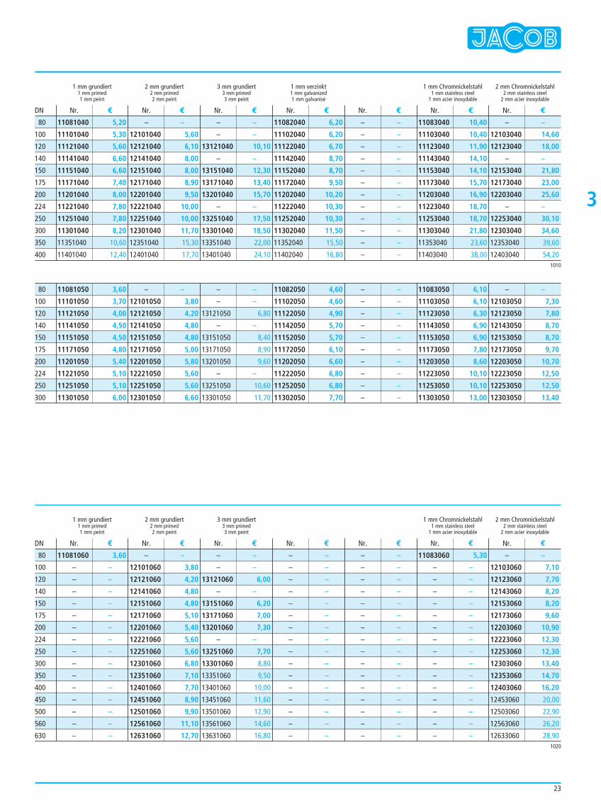
1 mm grundiert 2 mm grundiert 3 mm grundiert 1 mm verzinkt 1 mm Chromnickelstahl 2 mm Chromnickelstahl1 mm primed 2 mm primed 3 mm primed 1 mm galvanized 1 mm stainless steel 2 mm stainless steel1 mm peint 2 mm peint 3 mm peint 1 mm galvanisé 1 mm acier inoxydable 2 mm acier inoxydable
11081040 5,20
11101040 5,30
11121040 5,60
11141040 6,60
11151040 6,60
11171040 7,40
11201040 8,00
11221040 7,80
11251040 7,80
11301040 8,20
11351040 10,60
11401040 12,40
– –
12101040 5,60
12121040 6,10
12141040 8,00
12151040 8,00
12171040 8,90
12201040 9,50
12221040 10,00
12251040 10,00
12301040 11,70
12351040 15,30
12401040 17,70
– –
– –
13121040 10,10
– –
13151040 12,30
13171040 13,40
13201040 15,70
– –
13251040 17,50
13301040 18,50
13351040 22,00
13401040 24,10
11082040 6,20
11102040 6,20
11122040 6,70
11142040 8,70
11152040 8,70
11172040 9,50
11202040 10,20
11222040 10,30
11252040 10,30
11302040 11,50
11352040 15,50
11402040 16,80
– –
– –
– –
– –
– –
– –
– –
– –
– –
– –
– –
– –
11083040 10,40
11103040 10,40
11123040 11,90
11143040 14,10
11153040 14,10
11173040 15,70
11203040 16,90
11223040 18,70
11253040 18,70
11303040 21,80
11353040 23,60
11403040 38,00
– –
12103040 14,60
12123040 18,00
– –
12153040 21,80
12173040 23,00
12203040 25,60
– –
12253040 30,10
12303040 34,60
12353040 39,60
12403040 54,20
Nr. € Nr. € Nr. € Nr. € Nr. € Nr. € Nr. €DN
1 mm grundiert 2 mm grundiert 3 mm grundiert 1 mm Chromnickelstahl 2 mm Chromnickelstahl1 mm primed 2 mm primed 3 mm primed 1 mm stainless steel 2 mm stainless steel1 mm peint 2 mm peint 3 mm peint 1 mm acier inoxydable 2 mm acier inoxydable
Nr. € Nr. € Nr. € Nr. € Nr. € Nr. € Nr. €DN
1010
1020
80
100
120
140
150
175
200
224
250
300
350
400
11081050 3,60
11101050 3,70
11121050 4,00
11141050 4,50
11151050 4,50
11171050 4,80
11201050 5,40
11221050 5,10
11251050 5,10
11301050 6,00
– –
12101050 3,80
12121050 4,20
12141050 4,80
12151050 4,80
12171050 5,00
12201050 5,80
12221050 5,60
12251050 5,60
12301050 6,60
– –
– –
13121050 6,80
– –
13151050 8,40
13171050 8,90
13201050 9,60
– –
13251050 10,60
13301050 11,70
11082050 4,60
11102050 4,60
11122050 4,90
11142050 5,70
11152050 5,70
11172050 6,10
11202050 6,60
11222050 6,80
11252050 6,80
11302050 7,70
– –
– –
– –
– –
– –
– –
– –
– –
– –
– –
11083050 6,10
11103050 6,10
11123050 6,30
11143050 6,90
11153050 6,90
11173050 7,80
11203050 8,60
11223050 10,10
11253050 10,10
11303050 13,00
– –
12103050 7,30
12123050 7,80
12143050 8,70
12153050 8,70
12173050 9,70
12203050 10,70
12223050 12,50
12253050 12,50
12303050 13,40
80
100
120
140
150
175
200
224
250
300
11081060 3,60
– –
– –
– –
– –
– –
– –
– –
– –
– –
– –
– –
– –
– –
– –
– –
– –
12101060 3,80
12121060 4,20
12141060 4,80
12151060 4,80
12171060 5,10
12201060 5,40
12221060 5,60
12251060 5,60
12301060 6,80
12351060 7,10
12401060 7,70
12451060 8,90
12501060 9,90
12561060 11,10
12631060 12,70
– –
– –
13121060 6,00
– –
13151060 6,20
13171060 7,00
13201060 7,30
– –
13251060 7,70
13301060 8,80
13351060 9,50
13401060 10,00
13451060 11,60
13501060 12,90
13561060 14,60
13631060 16,80
– –
– –
– –
– –
– –
– –
– –
– –
– –
– –
– –
– –
– –
– –
– –
– –
– –
– –
– –
– –
– –
– –
– –
– –
– –
– –
– –
– –
– –
– –
– –
– –
11083060 5,30
– –
– –
– –
– –
– –
– –
– –
– –
– –
– –
– –
– –
– –
– –
– –
– –
12103060 7,10
12123060 7,70
12143060 8,20
12153060 8,20
12173060 9,60
12203060 10,90
12223060 12,30
12253060 12,30
12303060 13,40
12353060 14,70
12403060 16,20
12453060 20,00
12503060 22,90
12563060 26,20
12633060 28,90
80
100
120
140
150
175
200
224
250
300
350
400
450
500
560
630
3
24
80 77 25 75 – – – 990 1,85
100 100 25 96 – – – 990 3,50
120 120 25 116 – – – 990 4,30
140 136 25 132 – – – 990 4,60
150 150 25 146 – – – 990 5,40
175 175 25 171 – – – 990 6,20
200 200 25 196 – – – 990 7,00
224 220 25 216 – – – 990 7,60
250 250 25 246 – – – 990 8,80
300 300 25 296 – – – 990 10,70
350 350 50 346 – – – 990 12,40
400 399 50 396 – – – 990 14,20
Abmessungen für 1,5 mm RohrteileDimensions for 1.5 mm pipingDimensions pour tuyauterie en épaisseur 1,5 mm
Nennlänge 1000 mmNominal length 1000 mm
Longueur nominale 1000 mm
DN Ø d A B C E F L kg
80 – 68 – – – – – –
100 – 87 – – – – – –
120 – 106 – – – – – –
140 – 121 – – – – – –
150 – 138 – – – – – –
175 – 162 – – – – – –
200 – 186 – – – – – –
224 – 205 – – – – – –
250 – 233 – – – – – –
300 – 281 – – – – – –
350 – 328 – – – – – –
400 – 376 – – – – – –
AbmessungenDimensions Dimensions
DN Ø d A B C E F L kg
80 77 25 75 – – – 492 0,95
100 100 25 96 – – – 492 1,80
120 120 25 116 – – – 492 2,10
140 136 25 132 – – – 492 2,45
150 150 25 146 – – – 492 2,65
175 175 25 171 – – – 492 3,10
200 200 25 196 – – – 492 3,50
224 220 25 216 – – – 492 3,90
250 250 25 246 – – – 492 4,50
300 300 25 296 – – – 492 5,40
350 350 50 346 – – – 492 6,20
400 399 50 396 – – – 492 7,20
Nennlänge 500 mmNominal length 500 mm
Longueur nominale 500 mm
80 77 25 75 – – – 200 0,40
100 100 25 96 – – – 200 0,75
120 120 25 116 – – – 200 0,85
140 136 25 132 – – – 200 0,95
150 150 25 146 – – – 200 1,10
175 175 25 171 – – – 200 1,30
200 200 25 196 – – – 200 1,50
224 220 25 216 – – – 200 1,55
250 250 25 246 – – – 200 1,90
300 300 25 296 – – – 200 2,45
200 mm lang200 mm long
200 mm de long
A 9
B
d
A
L
Einschiebrohre
Push-in pipes
Tuyaux télescopiques
Verbindung bei 1 bis 2 mm RohrenConnection for pipes 1 to 2 mmLiaison avec tuyauterie 1 à 2 mm
Ringdichtungen zur Abdichtung von Einschiebrohren bei 1 bis 2 mm Wandstärke
Ring-seals to seal push-in pipes for 1 to 2 mm wall-thickness
Joints annulaires pour l’étanchéité de tuyaux télescopiques pour 1 à 2 mm épaisseur
Zur Anpressung der Ringdichtung wird ein Spannring, wie auf Seite 16 aufgeführt, benötigt.To press on the ring seal a pull ring as listed up on page 16 is required.Pour presser le joint annulaire, il faut un collier de serrage comme indiqué à la page 16.
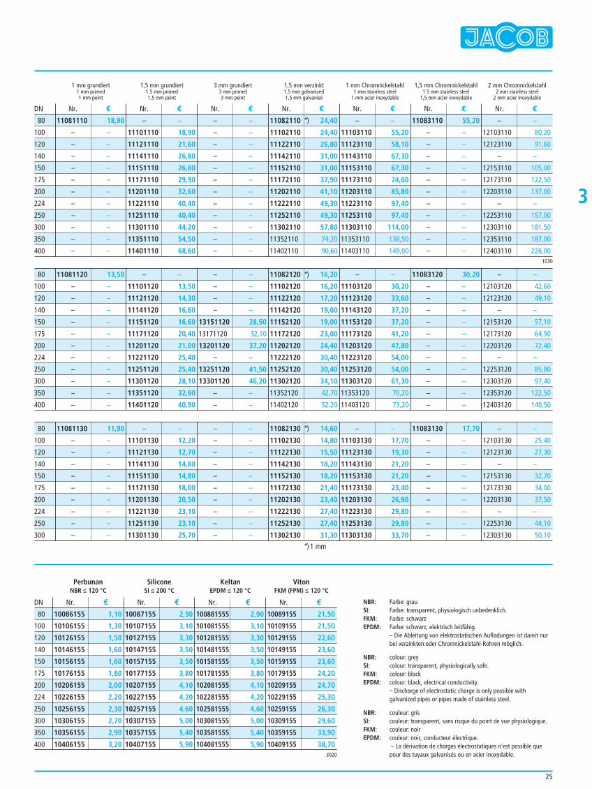
3
25
1 mm grundiert 1,5 mm grundiert 3 mm grundiert 1,5 mm verzinkt 1 mm Chromnickelstahl 1,5 mm Chromnickelstahl 2 mm Chromnickelstahl1 mm primed 1.5 mm primed 3 mm primed 1.5 mm galvanized 1 mm stainless steel 1.5 mm stainless steel 2 mm stainless steel1 mm peint 1,5 mm peint 3 mm peint 1,5 mm galvanisé 1 mm acier inoxydable 1,5 mm acier inoxydable 2 mm acier inoxydable
Nr. € Nr. € Nr. € Nr. € Nr. € Nr. € Nr. €DN
1030
80
100
120
140
150
175
200
224
250
300
350
400
Perbunan Silicone Keltan VitonNBR ≤ 120 °C SI ≤ 200 °C EPDM ≤ 120 °C FKM (FPM) ≤ 120 °C
10086155 1,10
10106155 1,30
10126155 1,50
10146155 1,60
10156155 1,60
10176155 1,80
10206155 2,00
10226155 2,20
10256155 2,30
10306155 2,70
10356155 2,90
10406155 3,20
10087155 2,90
10107155 3,10
10127155 3,30
10147155 3,50
10157155 3,50
10177155 3,80
10207155 4,10
10227155 4,20
10257155 4,60
10307155 5,00
10357155 5,40
10407155 5,90
100881555 2,90
101081555 3,10
101281555 3,30
101481555 3,50
101581555 3,50
101781555 3,80
102081555 4,10
102281555 4,20
102581555 4,60
103081555 5,00
103581555 5,40
104081555 5,90
10089155 21,50
10109155 21,50
10129155 22,60
10149155 23,60
10159155 23,60
10179155 24,20
10209155 24,70
10229155 25,30
10259155 26,30
10309155 29,60
10359155 33,90
10409155 38,70
Nr. € Nr. € Nr. € Nr. €DN
3020
80
100
120
140
150
175
200
224
250
300
350
400
11081120 13,50
– –
– –
– –
– –
– –
– –
– –
– –
– –
– –
– –
– –
11101120 13,50
11121120 14,30
11141120 16,60
11151120 16,60
11171120 20,40
11201120 21,00
11221120 25,40
11251120 25,40
11301120 28,10
11351120 32,90
11401120 40,90
– –
– –
– –
– –
13151120 28,50
13171120 32,10
13201120 37,20
– –
13251120 41,50
13301120 46,20
– –
– –
11082120 *) 16,20
11102120 16,20
11122120 17,20
11142120 19,00
11152120 19,00
11172120 23,00
11202120 24,40
11222120 30,40
11252120 30,40
11302120 34,10
11352120 42,70
11402120 52,20
– –
11103120 30,20
11123120 33,60
11143120 37,20
11153120 37,20
11173120 41,20
11203120 47,80
11223120 54,00
11253120 54,00
11303120 61,30
11353120 70,20
11403120 73,20
11083120 30,20
– –
– –
– –
– –
– –
– –
– –
– –
– –
– –
– –
– –
12103120 42,60
12123120 49,10
– –
12153120 57,10
12173120 64,90
12203120 72,40
– –
12253120 85,80
12303120 97,40
12353120 122,50
12403120 140,50
80
100
120
140
150
175
200
224
250
300
350
400
11081130 11,90
– –
– –
– –
– –
– –
– –
– –
– –
– –
– –
11101130 12,20
11121130 12,70
11141130 14,80
11151130 14,80
11171130 18,00
11201130 20,50
11221130 23,10
11251130 23,10
11301130 25,70
– –
– –
– –
– –
– –
– –
– –
– –
– –
– –
11082130 *) 14,60
11102130 14,80
11122130 15,50
11142130 18,20
11152130 18,20
11172130 21,40
11202130 23,40
11222130 27,40
11252130 27,40
11302130 31,30
– –
11103130 17,70
11123130 19,30
11143130 21,20
11153130 21,20
11173130 23,40
11203130 26,90
11223130 29,80
11253130 29,80
11303130 33,70
11083130 17,70
– –
– –
– –
– –
– –
– –
– –
– –
– –
– –
12103130 25,40
12123130 27,30
– –
12153130 32,70
12173130 34,00
12203130 37,50
– –
12253130 44,10
12303130 50,10
80
100
120
140
150
175
200
224
250
300
NBR: Farbe: grauSI: Farbe: transparent, physiologisch unbedenklich.FKM: Farbe: schwarzEPDM: Farbe: schwarz, elektrisch leitfähig.
– Die Ableitung von elektrostatischen Aufladungen ist damit nurbei verzinkten oder Chromnickelstahl-Rohren möglich.
NBR: colour: greySI: colour: transparent, physiologically safe.FKM: colour: blackEPDM: colour: black, electrical conductivity.
– Discharge of electrostatic charge is only possible withgalvanized pipes or pipes made of stainless steel.
NBR: couleur: grisSI: couleur: transparent, sans risque du point de vue physiologique.FKM: couleur: noirEPDM: couleur: noir, conducteur électrique.
– La dérivation de charges électrostatiques n'est possible quepour des tuyaux galvanisés ou en acier inoxydable.
*) 1 mm
11081110 18,90
– –
– –
– –
– –
– –
– –
– –
– –
– –
– –
– –
– –
11101110 18,90
11121110 21,60
11141110 26,80
11151110 26,80
11171110 29,90
11201110 32,60
11221110 40,40
11251110 40,40
11301110 44,20
11351110 54,50
11401110 68,60
– –
– –
– –
– –
– –
– –
– –
– –
– –
– –
– –
– –
11082110 *) 24,40
11102110 24,40
11122110 26,80
11142110 31,00
11152110 31,00
11172110 37,90
11202110 41,10
11222110 49,30
11252110 49,30
11302110 57,80
11352110 74,20
11402110 90,60
– –
11103110 55,20
11123110 58,10
11143110 67,30
11153110 67,30
11173110 74,60
11203110 85,80
11223110 97,40
11253110 97,40
11303110 114,00
11353110 138,50
11403110 149,00
11083110 55,20
– –
– –
– –
– –
– –
– –
– –
– –
– –
– –
– –
– –
12103110 80,20
12123110 91,60
– –
12153110 105,00
12173110 122,50
12203110 137,00
– –
12253110 157,00
12303110 181,50
12353110 187,00
12403110 226,00
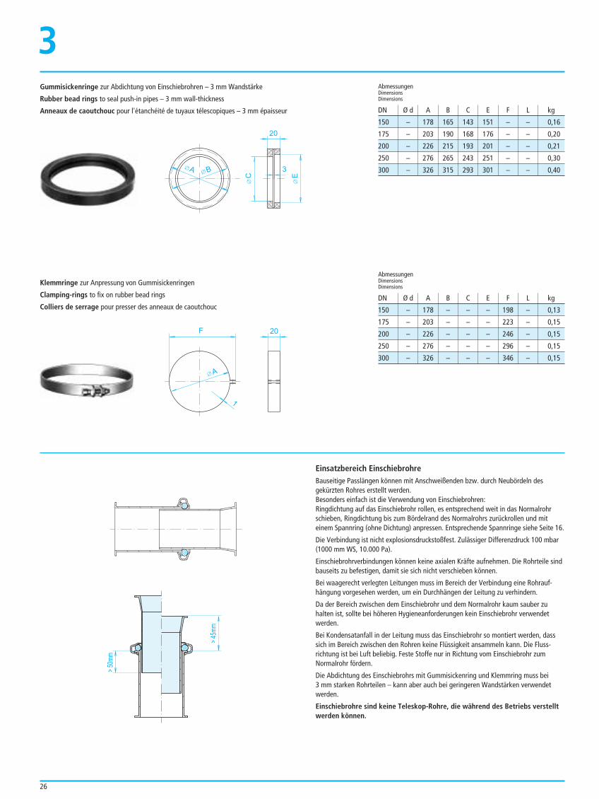
26
Gummisickenringe zur Abdichtung von Einschiebrohren – 3 mm Wandstärke
Rubber bead rings to seal push-in pipes – 3 mm wall-thickness
Anneaux de caoutchouc pour l'étanchéité de tuyaux télescopiques – 3 mm épaisseur
3
Klemmringe zur Anpressung von Gummisickenringen
Clamping-rings to fix on rubber bead rings
Colliers de serrage pour presser des anneaux de caoutchouc
Einsatzbereich EinschiebrohreBauseitige Passlängen können mit Anschweißenden bzw. durch Neubördeln desgekürzten Rohres erstellt werden.Besonders einfach ist die Verwendung von Einschiebrohren:Ringdichtung auf das Einschiebrohr rollen, es entsprechend weit in das Normalrohrschieben, Ringdichtung bis zum Bördelrand des Normalrohrs zurückrollen und miteinem Spannring (ohne Dichtung) anpressen. Entsprechende Spannringe siehe Seite 16.
Die Verbindung ist nicht explosionsdruckstoßfest. Zulässiger Differenzdruck 100 mbar(1000 mm WS, 10.000 Pa).
Einschiebrohrverbindungen können keine axialen Kräfte aufnehmen. Die Rohrteile sindbauseits zu befestigen, damit sie sich nicht verschieben können.
Bei waagerecht verlegten Leitungen muss im Bereich der Verbindung eine Rohrauf-hängung vorgesehen werden, um ein Durchhängen der Leitung zu verhindern.
Da der Bereich zwischen dem Einschiebrohr und dem Normalrohr kaum sauber zuhalten ist, sollte bei höheren Hygieneanforderungen kein Einschiebrohr verwendetwerden.
Bei Kondensatanfall in der Leitung muss das Einschiebrohr so montiert werden, dasssich im Bereich zwischen den Rohren keine Flüssigkeit ansammeln kann. Die Fluss-richtung ist bei Luft beliebig. Feste Stoffe nur in Richtung vom Einschiebrohr zumNormalrohr fördern.
Die Abdichtung des Einschiebrohrs mit Gummisickenring und Klemmring muss bei 3 mm starken Rohrteilen – kann aber auch bei geringeren Wandstärken verwendetwerden.
Einschiebrohre sind keine Teleskop-Rohre, die während des Betriebs verstelltwerden können.
20
BA
C
3
E
> 50
mm
> 45
mm
F 20
1
A
150 – 178 165 143 151 – – 0,16
175 – 203 190 168 176 – – 0,20
200 – 226 215 193 201 – – 0,21
250 – 276 265 243 251 – – 0,30
300 – 326 315 293 301 – – 0,40
AbmessungenDimensionsDimensions
DN Ø d A B C E F L kg
AbmessungenDimensionsDimensions
DN Ø d A B C E F L kg
150 – 178 – – – 198 – 0,13
175 – 203 – – – 223 – 0,15
200 – 226 – – – 246 – 0,15
250 – 276 – – – 296 – 0,15
300 – 326 – – – 346 – 0,15
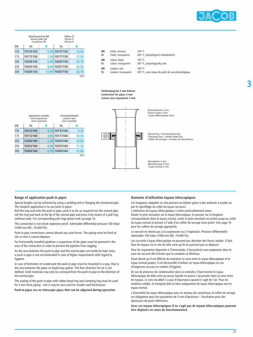
27
3
Range of application push-in pipesSpecial lengths can be achieved by using a welding end or flanging the shortened pipe.The simplest application is to use push-in pipes:Roll the ring seal onto the push-in pipe, push it as far as required into the normal pipe,roll the ring seal back to the lip of the normal pipe and press it by means of a pull ring(without seal). For corresponding pull rings please look up page 16.
This connection is not shock-explosion proof. Admissible differential pressure 100 mbar(1000 mm WC, 10.000 PA).
Push-in pipe connections cannot absorb any axial forces. The piping must be fixed atsite so that it cannot displace.
For horizontally installed pipelines a suspension of the pipes must be planned in thearea of the connection in order to prevent the pipeline from sagging.
As the area between the push-in pipe and the normal pipe can hardly be kept clean, a push-in pipe is not recommended in case of higher requirements with regard tohygiene.
In case of formation of condensate the push-in pipe must be mounted in a way, that inthe area between the pipes no liquid may gather. The flow direction for air is notdefined. Solid materials may only be conveyed from the push-in pipe to the direction ofthe normal pipe.
The sealing of the push-in pipe with rubber bead ring and clamping ring must be usedfor 3 mm thick piping – but it may be also used for smaller wall thicknesses.
Push-in pipes are no telescopic pipes that can be adjusted during operation.
Domaine d'utilisation tuyaux télescopiquesLes longueurs adaptées au site peuvent se réaliser grâce à des embouts à souder oupar le reprofilage du collet du tuyau raccourci.L'utilisation de tuyaux télescopiques s'avère particulièrement aisée :Rouler le joint annulaire sur le tuyau télescopique, le pousser sur la longueurcorrespondante dans le tuyau normal, rouler le joint annulaire en arrière jusqu'au colletdu tuyau normal et presser à l'aide d'un collier de serrage (sans joint). Voir page 16pour les colliers de serrage appropriés.
Le raccord ne résiste pas à la surpression ou à l'explosion. Pression différentielleadmissible 100 mbar (1000 mm WS, 10.000 Pa).
Les raccords à tuyau télescopique ne peuvent pas absorber des forces axiales. Il fautfixer les tuyaux sur le site de telle sorte qu'ils ne puissent pas se déplacer.
Pour les tuyauteries disposées à l'horizontale, il faut prévoir une suspension dans lazone du raccord afin d'éviter que la conduite ne fléchisse.
Etant donné qu'il est difficile de maintenir la zone entre le tuyau télescopique et letuyau normal propre, il est déconseillé d'utiliser un tuyau télescopique en casd'exigences accrues en matière d'hygiène.
En cas de présence de condensation dans la conduite, il faut monter le tuyautélescopique de telle sorte qu'aucun liquide ne puisse s'accumuler dans la zone entreles tuyaux. Le sens du débit n'a pas d'importance quand il s'agit de l'air. Pour lesmatières solides, le transport doit se faire uniquement du tuyau télescopique vers letuyau normal.
L'étanchéité du tuyau télescopique avec un anneau de caoutchouc et collier de serrageest obligatoire pour les tuyauteries de 3 mm d'épaisseur – facultative pour desépaisseurs de paroi inférieures.
Avec ces tuyaux télescopiques il ne s'agit pas de tuyaux télescopiques pouvantêtre déplacés en cours de fonctionnement.
Naturkautschuk NRNatural rubber NR
Caoutchouc NR
Silikon SISilicone SISilicone SI
Nr. € Nr. €DN
3010
150
175
200
250
300
10155150 6,00
10175150 7,30
10205150 8,00
10255150 8,60
10305150 12,90
10157150 14,40
10177150 17,50
10207150 19,10
10257150 23,50
10307150 28,10
galvanisch verzinktelectro galvanizedelectro galvanisé
Chromnickelstahlstainless steel
acier inoxydable
Nr. € Nr. €DN
3015
150
175
200
250
300
10153160 9,30
10173160 10,50
10203160 10,60
10253160 11,30
10303160 12,00
NR: Farbe: schwarz 100 °CSI: Farbe: transparent 200 °C, physiologisch unbedenklich.
NR: colour: black 100 °CSI: colour: transparent 200 °C, physiologically safe.
NR: couleur: noir 100 °CSI: couleur: transparent 200 °C, sans risque du point de vue physiologique.
Klemmring + GummisickenringClamping ring + rubber bead ringCollier de serrage + anneau de caoutchouc
Normalrohr 3 mmStandard pipe 3 mmTuyau normal 3 mm
Einschiebrohr 3 mmPush-in pipe 3 mmTuyau télescopique 3mm
Verbindung bei 3 mm RohrenConnection for pipes 3 mmLiaison avec tuyauterie 3 mm
10152160 4,10
10172160 4,80
10202160 5,40
10252160 6,00
10302160 6,70
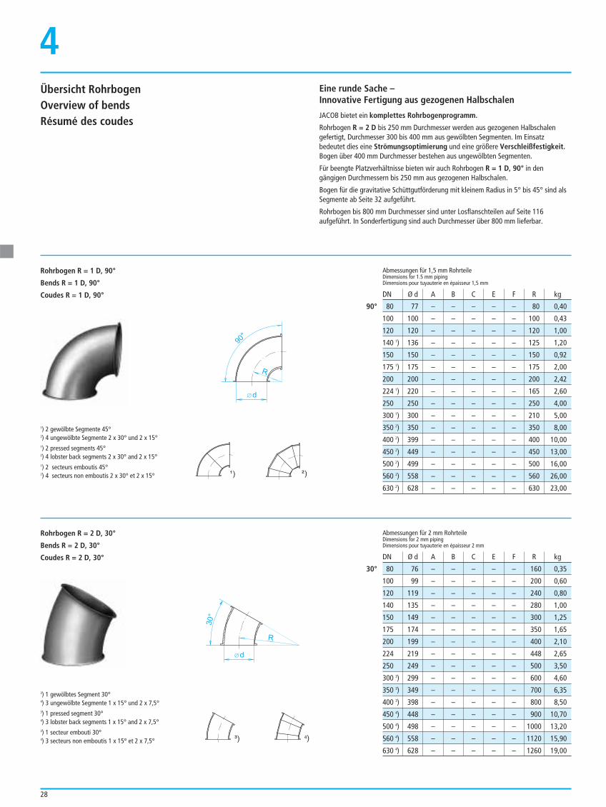
4Eine runde Sache –Innovative Fertigung aus gezogenen Halbschalen
JACOB bietet ein komplettes Rohrbogenprogramm.
Rohrbogen R = 2 D bis 250 mm Durchmesser werden aus gezogenen Halbschalengefertigt, Durchmesser 300 bis 400 mm aus gewölbten Segmenten. Im Einsatzbedeutet dies eine Strömungsoptimierung und eine größere Verschleißfestigkeit.Bogen über 400 mm Durchmesser bestehen aus ungewölbten Segmenten.
Für beengte Platzverhältnisse bieten wir auch Rohrbogen R = 1 D, 90° in dengängigen Durchmessern bis 250 mm aus gezogenen Halbschalen.
Bogen für die gravitative Schüttgutförderung mit kleinem Radius in 5° bis 45° sind alsSegmente ab Seite 32 aufgeführt.
Rohrbogen bis 800 mm Durchmesser sind unter Losflanschteilen auf Seite 116aufgeführt. In Sonderfertigung sind auch Durchmesser über 800 mm lieferbar.
Übersicht RohrbogenOverview of bendsRésumé des coudes
80 77 – – – – – 80 0,40
100 100 – – – – – 100 0,43
120 120 – – – – – 120 1,00
140 1) 136 – – – – – 125 1,20
150 150 – – – – – 150 0,92
175 1) 175 – – – – – 175 2,00
200 200 – – – – – 200 2,42
224 1) 220 – – – – – 165 2,60
250 250 – – – – – 250 4,00
300 1) 300 – – – – – 210 5,00
350 2) 350 – – – – – 350 8,00
400 2) 399 – – – – – 400 10,00
450 2) 449 – – – – – 450 13,00
500 2) 499 – – – – – 500 16,00
560 2) 558 – – – – – 560 26,00
630 2) 628 – – – – – 630 23,00
Abmessungen für 1,5 mm RohrteileDimensions for 1.5 mm pipingDimensions pour tuyauterie en épaisseur 1,5 mm
90°
80 76 – – – – – 160 0,35
100 99 – – – – – 200 0,60
120 119 – – – – – 240 0,80
140 135 – – – – – 280 1,00
150 149 – – – – – 300 1,25
175 174 – – – – – 350 1,65
200 199 – – – – – 400 2,10
224 219 – – – – – 448 2,65
250 249 – – – – – 500 3,50
300 3) 299 – – – – – 600 4,60
350 3) 349 – – – – – 700 6,35
400 3) 398 – – – – – 800 8,50
450 4) 448 – – – – – 900 10,70
500 4) 498 – – – – – 1000 13,20
560 4) 558 – – – – – 1120 15,90
630 4) 628 – – – – – 1260 19,00
30°
DN Ø d A B C E F R kg
Abmessungen für 2 mm RohrteileDimensions for 2 mm pipingDimensions pour tuyauterie en épaisseur 2 mm
DN Ø d A B C E F R kg
Rohrbogen R = 1 D, 90°
Bends R = 1 D, 90°
Coudes R = 1 D, 90°
Rohrbogen R = 2 D, 30°
Bends R = 2 D, 30°
Coudes R = 2 D, 30°
3) 1 gewölbtes Segment 30°4) 3 ungewölbte Segmente 1 x 15° und 2 x 7,5°3) 1 pressed segment 30°4) 3 lobster back segments 1 x 15° and 2 x 7,5°3) 1 secteur embouti 30°4) 3 secteurs non emboutis 1 x 15° et 2 x 7,5°
d
R
90°
R
30°
d
28
1) 2 gewölbte Segmente 45°2) 4 ungewölbte Segmente 2 x 30° und 2 x 15°1) 2 pressed segments 45°2) 4 lobster back segments 2 x 30° and 2 x 15°1) 2 secteurs emboutis 45°2) 4 secteurs non emboutis 2 x 30° et 2 x 15°
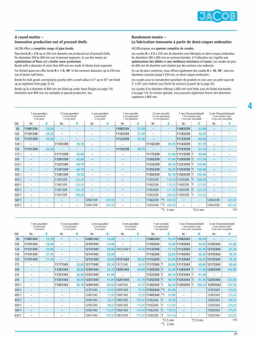
4
A round matter –Innovative production out of pressed shells
JACOB offers a complete range of pipe bends.
Pipe bends R = 2 D up to 250 mm diameter are produced out of pressed shells,for diameters 300 to 400 mm out of pressed segments. In use this means anoptimization of flow and a better wear protection.Bends with a diameter of more than 400 mm are made of lobster back segments.
For limited space we offer bends R = 1 D, 90° in the common diameters up to 250 mmout of drawn half-liners.
Bends for bulk goods conveying by gravity with a small radius in 5° up to 45° are listedup as segments from page 32 on.
Bends up to a diameter of 800 mm are listed up under loose flanges on page 116.Diameters over 800 mm are available as special production, too.
Rondement menée – La fabrication innovante à partir de demi-coques embouties
JACOB propose une gamme complète de coudes.
Les coudes R = 2 D à 250 mm de diamètre sont fabriqués en demi-coques embouties, les diamètres 300 à 400 mm en secteurs bombés. A l'utilisation ceci signifie uneoptimisation des débits et une meilleure résistance à l'usure. Les coudes de plusde 400 mm de diamètre sont réalisés par des secteurs non emboutis.
En cas de place restreinte, nous offrons également des coudes R = 1D, 90°, dans lesdiamètres courants jusqu’à 250 mm, en demi-coques embouties.
Les coudes pour la manutention gravitaire de produits en vrac avec un petit rayon de5° à 45° sont réalisés sous forme de secteurs (à partir de la page 32).
Les coudes d'un diamètre inférieur à 800 mm sont listés sous les brides tournantes à la page 116. En version spéciale, nous pouvons également fournir des diamètressupérieurs à 800 mm.
1 mm grundiert 1,5 mm grundiert 2 mm grundiert 1 mm verzinkt 1,5 mm verzinkt 1 mm Chromnickelstahl 2 mm Chromnickelstahl1 mm primed 1.5 mm primed 2 mm primed 1 mm galvanized 1.5 mm galvanized 1 mm stainless steel 2 mm stainless steel1 mm peint 1,5 mm peint 2 mm peint 1 mm galvanisé 1,5 mm galvanisé 1 mm acier inoxydable 2 mm acier inoxydable
1 mm grundiert 1,5 mm grundiert 2 mm grundiert 3 mm grundiert 1 mm verzinkt 1 mm Chromnickelstahl 2 mm Chromnickelstahl1 mm primed 1.5 mm primed 2 mm primed 3 mm primed 1 mm galvanized 1 mm stainless steel 2 mm stainless steel1 mm peint 1,5 mm peint 2 mm peint 3 mm peint 1 mm galvanisé 1 mm acier inoxydable 2 mm acier inoxydable
11081339 24,20
11101339 24,20
11121339 33,40
– –
11151339 35,70
– –
– –
– –
– –
– –
– –
– –
– –
– –
– –
– –
– –
– –
– –
11141339 35,70
– –
11171339 42,00
11201339 42,80
11221339 64,70
11251339 64,70
11301339 79,50
11351339 125,00
11401339 150,50
11451339 161,50
11501339 189,00
– –
– –
– –
– –
– –
– –
– –
– –
– –
– –
– –
– –
– –
– –
– –
– –
12561339 209,00
12631339 245,00
11082339 27,50
11102339 27,50
11122339 37,00
– –
11152339 39,70
– –
– –
– –
– –
– –
– –
– –
– –
– –
– –
– –
– –
– –
– –
11142339 39,70
– –
11172339 51,90
11202339 51,90
11222339 76,70
11252339 76,70
11302339 95,70
11352339 140,00
11402339 170,50
11452339 171,50
11502339 209,50
11562339 **) 265,00
11632339 **) 305,00
11083339 51,00
11103339 52,50
11123339 60,00
11143339 91,70
11153339 91,70
11173339 *) 95,00
11203339 *) 111,50
11223339 *) 126,00
11253339 *) 126,00
11303339 *) 146,50
11353339 *) 238,50
11403339 *) 277,00
11453339 *) 325,00
11503339 *) 370,00
– –
– –
– –
– –
– –
– –
– –
– –
– –
– –
– –
– –
– –
– –
– –
– –
12563339 433,50
12633339 467,00
Nr. € Nr. € Nr. € Nr. € Nr. € Nr. € Nr. €
Nr. € Nr. € Nr. € Nr. € Nr. € Nr. € Nr. €
DN
DN
1220
80
100
120
140 1)
150
175 1)
200
224 1)
250
300 1)
350 2)
400 2)
450 2)
500 2)
560 2)
630 2)
**) 2 mm **)1,5 mm
11081343 13,70
11101343 14,40
11121343 16,90
11141343 21,70
11151343 21,70
– –
– –
– –
– –
– –
– –
– –
– –
– –
– –
– –
– –
– –
– –
– –
– –
11171343 25,60
11201343 28,60
11221343 36,00
11251343 36,00
11301343 50,10
– –
– –
– –
– –
– –
– –
12081343 14,40
12101343 14,40
12121343 20,80
12141343 26,00
12151343 26,00
12171343 28,10
12201343 34,20
12221343 41,00
12251343 41,00
12301343 56,50
12351343 60,60
12401343 71,90
12451343 90,20
12501343 98,50
12561343 123,00
12631343 159,50
– –
– –
13121343 4) 44,90
– –
13151343 36,30
13171343 39,90
13201343 44,60
– –
13251343 57,70
13301343 65,00
13351343 70,50
13401343 79,30
13451343 102,00
13501343 119,00
13561343 144,50
13631343 171,00
11082343 14,70
11102343 15,40
11122343 17,10
11142343 22,60
11152343 22,60
11172343 *) 26,60
11202343 *) 32,40
11222343 *) 40,70
11252343 *) 40,70
11302343 *) 56,50
11352343 **) 65,30
11402343 **) 73,50
11452343 *) 94,90
11502343 *) 113,00
11562343 *) 130,00
11632343 *) 161,50
11083343 30,50
11103343 30,50
11123343 45,40
11143343 56,20
11153343 56,20
11173343 60,80
11203343 *) 71,60
11223343 *) 91,30
11253343 *) 91,30
11303343 *) 106,50
– –
– –
– –
– –
– –
– –
– –
12103343 41,90
12123343 61,30
12143343 78,30
12153343 78,30
12173343 85,60
12203343 102,00
– –
12253343 123,00
12303343 125,50
12353343 128,50
12403343 135,00
12453343 188,50
12503343 214,00
12563343 275,00
12633343 325,001230
80
100
120
140
150
175
200
224
250
300 3)
350 3)
400 3)
450 4)
500 4)
560 4)
630 4)
**)1,5 mm**) 2 mm
*) 1,5 mm
29
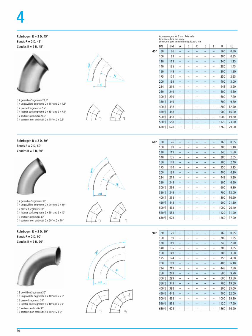
30
4
80 76 – – – – – 160 0,50
100 99 – – – – – 200 0,85
120 119 – – – – – 240 1,15
140 135 – – – – – 280 1,45
150 149 – – – – – 300 1,80
175 174 – – – – – 350 2,25
200 199 – – – – – 400 3,00
224 219 – – – – – 448 3,90
250 249 – – – – – 500 4,80
300 1) 299 – – – – – 600 7,20
350 1) 349 – – – – – 700 9,80
400 1) 398 – – – – – 800 12,70
450 2) 448 – – – – – 900 16,00
500 2) 498 – – – – – 1000 19,80
560 2) 558 – – – – – 1120 23,90
630 2) 628 – – – – – 1260 29,60
Abmessungen für 2 mm RohrteileDimensions for 2 mm pipingDimensions pour tuyauterie en épaisseur 2 mm
45°
80 76 – – – – – 160 0,65
100 99 – – – – – 200 1,10
120 119 – – – – – 240 1,50
140 135 – – – – – 280 2,05
150 149 – – – – – 300 2,40
175 174 – – – – – 350 3,15
200 199 – – – – – 400 4,10
224 219 – – – – – 448 5,20
250 249 – – – – – 500 6,90
300 1) 299 – – – – – 600 9,30
350 1) 349 – – – – – 700 13,00
400 1) 398 – – – – – 800 16,90
450 2) 448 – – – – – 900 21,30
500 2) 498 – – – – – 1000 26,40
560 2) 558 – – – – – 1120 31,90
630 2) 628 – – – – – 1260 37,90
60°
80 76 – – – – – 160 0,95
100 99 – – – – – 200 1,55
120 119 – – – – – 240 2,20
140 135 – – – – – 280 3,05
150 149 – – – – – 300 3,50
175 174 – – – – – 350 4,60
200 199 – – – – – 400 6,10
224 219 – – – – – 448 7,80
250 249 – – – – – 500 9,70
300 1) 299 – – – – – 600 13,50
350 1) 349 – – – – – 700 19,60
400 1) 398 – – – – – 800 25,00
450 2) 448 – – – – – 900 32,00
500 2) 498 – – – – – 1000 39,30
560 2) 558 – – – – – 1120 47,90
630 2) 628 – – – – – 1260 56,90
90°
DN Ø d A B C E F R kg
Rohrbogen R = 2 D, 45°
Bends R = 2 D, 45°
Coudes R = 2 D, 45°
Rohrbogen R = 2 D, 60°
Bends R = 2 D, 60°
Coudes R = 2 D, 60°
d
R
45°
d
R
60°
Rohrbogen R = 2 D, 90°
Bends R = 2 D, 90°
Coudes R = 2 D, 90°
1) 3 gewölbte Segmente 30°2) 6 ungewölbte Segmente 4 x 18° und 2 x 9°1) 3 pressed segments 30°2) 6 lobster back segments 4 x 18° and 2 x 9°1) 3 secteurs emboutis 30°2) 6 secteurs non emboutis 4 x 18° et 2 x 9°
d
R
90°
1) 2 gewölbte Segmente 22,5°2) 4 ungewölbte Segmente 2 x 15° und 2 x 7,5°1) 2 pressed segments 22,5°2) 4 lobster back segments 2 x 15° and 2 x 7,5°1) 2 secteurs emboutis 22,5°2) 4 secteurs non emboutis 2 x 15° et 2 x 7,5°
1) 2 gewölbte Segmente 30°2) 4 ungewölbte Segmente 2 x 20° und 2 x 10°1) 2 pressed segments 30°2) 4 lobster back segments 2 x 20° and 2 x 10°1) 2 secteurs emboutis 30°2) 4 secteurs non emboutis 2 x 20° et 2 x 10°
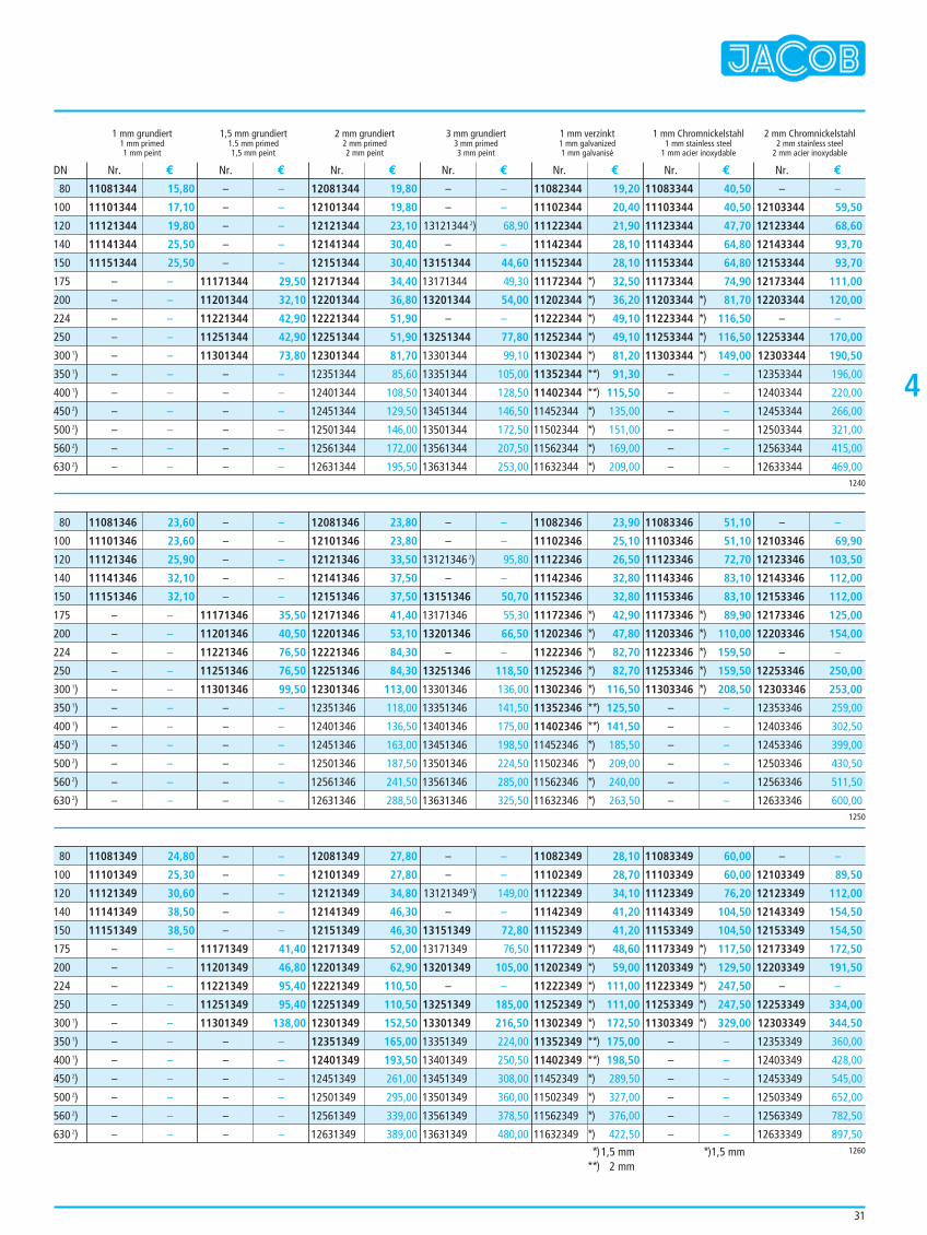
4
1 mm grundiert 1,5 mm grundiert 2 mm grundiert 3 mm grundiert 1 mm verzinkt 1 mm Chromnickelstahl 2 mm Chromnickelstahl1 mm primed 1.5 mm primed 2 mm primed 3 mm primed 1 mm galvanized 1 mm stainless steel 2 mm stainless steel1 mm peint 1,5 mm peint 2 mm peint 3 mm peint 1 mm galvanisé 1 mm acier inoxydable 2 mm acier inoxydable
11081344 15,80
11101344 17,10
11121344 19,80
11141344 25,50
11151344 25,50
– –
– –
– –
– –
– –
– –
– –
– –
– –
– –
– –
– –
– –
– –
– –
– –
11171344 29,50
11201344 32,10
11221344 42,90
11251344 42,90
11301344 73,80
– –
– –
– –
– –
– –
– –
12081344 19,80
12101344 19,80
12121344 23,10
12141344 30,40
12151344 30,40
12171344 34,40
12201344 36,80
12221344 51,90
12251344 51,90
12301344 81,70
12351344 85,60
12401344 108,50
12451344 129,50
12501344 146,00
12561344 172,00
12631344 195,50
– –
– –
13121344 2) 68,90
– –
13151344 44,60
13171344 49,30
13201344 54,00
– –
13251344 77,80
13301344 99,10
13351344 105,00
13401344 128,50
13451344 146,50
13501344 172,50
13561344 207,50
13631344 253,00
11082344 19,20
11102344 20,40
11122344 21,90
11142344 28,10
11152344 28,10
11172344 *) 32,50
11202344 *) 36,20
11222344 *) 49,10
11252344 *) 49,10
11302344 *) 81,20
11352344 **) 91,30
11402344 **) 115,50
11452344 *) 135,00
11502344 *) 151,00
11562344 *) 169,00
11632344 *) 209,00
11083344 40,50
11103344 40,50
11123344 47,70
11143344 64,80
11153344 64,80
11173344 74,90
11203344 *) 81,70
11223344 *) 116,50
11253344 *) 116,50
11303344 *) 149,00
– –
– –
– –
– –
– –
– –
– –
12103344 59,50
12123344 68,60
12143344 93,70
12153344 93,70
12173344 111,00
12203344 120,00
– –
12253344 170,00
12303344 190,50
12353344 196,00
12403344 220,00
12453344 266,00
12503344 321,00
12563344 415,00
12633344 469,00
Nr. € Nr. € Nr. € Nr. € Nr. € Nr. € Nr. €DN
1240
80
100
120
140
150
175
200
224
250
300 1)
350 1)
400 1)
450 2)
500 2)
560 2)
630 2)
11081346 23,60
11101346 23,60
11121346 25,90
11141346 32,10
11151346 32,10
– –
– –
– –
– –
– –
– –
– –
– –
– –
– –
– –
– –
– –
– –
– –
– –
11171346 35,50
11201346 40,50
11221346 76,50
11251346 76,50
11301346 99,50
– –
– –
– –
– –
– –
– –
12081346 23,80
12101346 23,80
12121346 33,50
12141346 37,50
12151346 37,50
12171346 41,40
12201346 53,10
12221346 84,30
12251346 84,30
12301346 113,00
12351346 118,00
12401346 136,50
12451346 163,00
12501346 187,50
12561346 241,50
12631346 288,50
– –
– –
13121346 2) 95,80
– –
13151346 50,70
13171346 55,30
13201346 66,50
– –
13251346 118,50
13301346 136,00
13351346 141,50
13401346 175,00
13451346 198,50
13501346 224,50
13561346 285,00
13631346 325,50
11082346 23,90
11102346 25,10
11122346 26,50
11142346 32,80
11152346 32,80
11172346 *) 42,90
11202346 *) 47,80
11222346 *) 82,70
11252346 *) 82,70
11302346 *) 116,50
11352346 **) 125,50
11402346 **) 141,50
11452346 *) 185,50
11502346 *) 209,00
11562346 *) 240,00
11632346 *) 263,50
11083346 51,10
11103346 51,10
11123346 72,70
11143346 83,10
11153346 83,10
11173346 *) 89,90
11203346 *) 110,00
11223346 *) 159,50
11253346 *) 159,50
11303346 *) 208,50
– –
– –
– –
– –
– –
– –
– –
12103346 69,90
12123346 103,50
12143346 112,00
12153346 112,00
12173346 125,00
12203346 154,00
– –
12253346 250,00
12303346 253,00
12353346 259,00
12403346 302,50
12453346 399,00
12503346 430,50
12563346 511,50
12633346 600,001250
80
100
120
140
150
175
200
224
250
300 1)
350 1)
400 1)
450 2)
500 2)
560 2)
630 2)
11081349 24,80
11101349 25,30
11121349 30,60
11141349 38,50
11151349 38,50
– –
– –
– –
– –
– –
– –
– –
– –
– –
– –
– –
– –
– –
– –
– –
– –
11171349 41,40
11201349 46,80
11221349 95,40
11251349 95,40
11301349 138,00
– –
– –
– –
– –
– –
– –
12081349 27,80
12101349 27,80
12121349 34,80
12141349 46,30
12151349 46,30
12171349 52,00
12201349 62,90
12221349 110,50
12251349 110,50
12301349 152,50
12351349 165,00
12401349 193,50
12451349 261,00
12501349 295,00
12561349 339,00
12631349 389,00
– –
– –
13121349 2) 149,00
– –
13151349 72,80
13171349 76,50
13201349 105,00
– –
13251349 185,00
13301349 216,50
13351349 224,00
13401349 250,50
13451349 308,00
13501349 360,00
13561349 378,50
13631349 480,00
11082349 28,10
11102349 28,70
11122349 34,10
11142349 41,20
11152349 41,20
11172349 *) 48,60
11202349 *) 59,00
11222349 *) 111,00
11252349 *) 111,00
11302349 *) 172,50
11352349 **) 175,00
11402349 **) 198,50
11452349 *) 289,50
11502349 *) 327,00
11562349 *) 376,00
11632349 *) 422,50
11083349 60,00
11103349 60,00
11123349 76,20
11143349 104,50
11153349 104,50
11173349 *) 117,50
11203349 *) 129,50
11223349 *) 247,50
11253349 *) 247,50
11303349 *) 329,00
– –
– –
– –
– –
– –
– –
– –
12103349 89,50
12123349 112,00
12143349 154,50
12153349 154,50
12173349 172,50
12203349 191,50
– –
12253349 334,00
12303349 344,50
12353349 360,00
12403349 428,00
12453349 545,00
12503349 652,00
12563349 782,50
12633349 897,501260
80
100
120
140
150
175
200
224
250
300 1)
350 1)
400 1)
450 2)
500 2)
560 2)
630 2)
**)1,5 mm**) 2 mm
**)1,5 mm
31
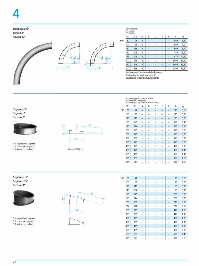
32
4
80 76 0 – – – – 500 3,40
100 99 0 – – – – 500 4,10
120 119 0 – – – – 600 5,70
150 149 0 – – – – 750 13,50
175 175 0 – – – – 875 12,40
200 2) 199 100 – – – – 1000 26,20
250 2) 249 100 – – – – 1000 32,80
300 2) 299 100 – – – – 1200 46,40
AbmessungenDimensionsDimensions
90°
DN Ø d A B C E F R kg
Abmessungen für 2 mm RohrteileDimensions for 2 mm pipingDimensions pour tuyauterie en épaisseur 2 mm
DN Ø d A B C E F R kg
Rohrbogen 90°
Bends 90°
Coudes 90°
1) 1 ungewölbtes Segment1) 1 lobster back segment1) 1 secteur non embouti
Segmente 5°
Segments 5°
Secteurs 5°
Segmente 15°
Segments 15°
Secteurs 15°
d
R
5°
1) 1 ungewölbtes Segment1) 1 lobster back segment1) 1 secteur non embouti
d
R
15°
Rohrbogen mit Zwischenwinkel auf Anfrage.Bends with other angles on request.Coudes avec autres rayons sur demande.
80 78 – – – – – 240 0,10
100 99 – – – – – 215 0,20
120 119 – – – – – 295 0,25
150 149 – – – – – 600 0,45
175 174 – – – – – 560 0,55
200 199 – – – – – 690 0,65
250 249 – – – – – 635 0,75
300 299 – – – – – 625 0,95
350 1) 349 – – – – – 350 0,80
400 1) 399 – – – – – 400 0,95
450 1) 449 – – – – – 450 1,40
500 1) 499 – – – – – 500 1,45
560 1) 557 – – – – – 560 1,60
630 1) 627 – – – – – 630 2,15
5°
80 78 – – – – – 130 0,10
100 99 – – – – – 130 0,20
120 119 – – – – – 155 0,30
140 136 – – – – – 185 0,30
150 149 – – – – – 250 0,55
175 174 – – – – – 280 0,75
200 199 – – – – – 270 0,80
224 220 – – – – – 220 0,55
250 249 – – – – – 310 1,05
300 299 – – – – – 310 1,30
350 1) 349 – – – – – 350 1,75
400 1) 399 – – – – – 400 2,35
450 1) 449 – – – – – 450 2,95
500 1) 499 – – – – – 500 3,50
560 1) 557 – – – – – 560 4,40
630 1) 627 – – – – – 630 5,60
15°
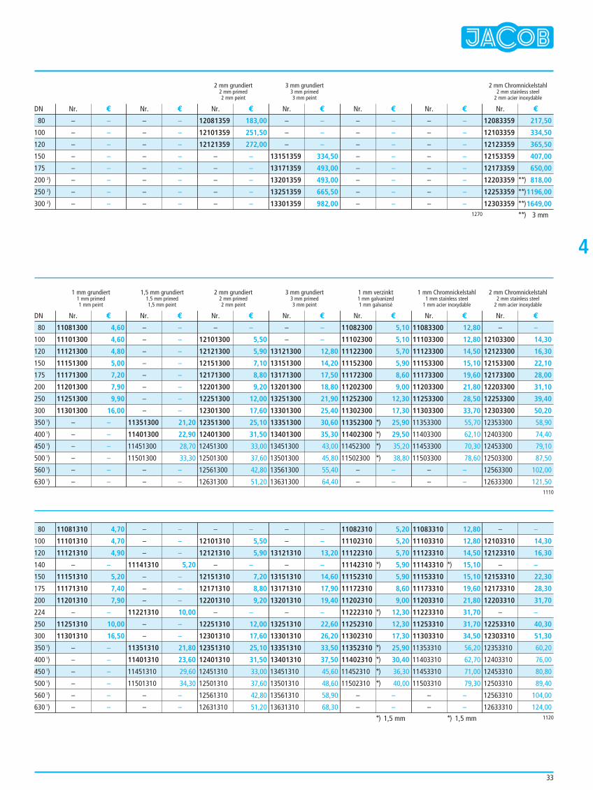
33
4
2 mm grundiert 3 mm grundiert 2 mm Chromnickelstahl2 mm primed 3 mm primed 2 mm stainless steel2 mm peint 3 mm peint 2 mm acier inoxydable
– –
– –
– –
– –
– –
– –
– –
– –
– –
– –
– –
– –
– –
– –
– –
– –
12081359 183,00
12101359 251,50
12121359 272,00
– –
– –
– –
– –
– –
– –
– –
– –
13151359 334,50
13171359 493,00
13201359 493,00
13251359 665,50
13301359 982,00
– –
– –
– –
– –
– –
– –
– –
– –
– –
– –
– –
– –
– –
– –
– –
– –
12083359 217,50
12103359 334,50
12123359 365,50
12153359 407,00
12173359 650,00
12203359 **) 818,00
12253359 **)1196,00
12303359 **)1649,00
Nr. € Nr. € Nr. € Nr. € Nr. € Nr. € Nr. €DN
1 mm grundiert 1,5 mm grundiert 2 mm grundiert 3 mm grundiert 1 mm verzinkt 1 mm Chromnickelstahl 2 mm Chromnickelstahl1 mm primed 1.5 mm primed 2 mm primed 3 mm primed 1 mm galvanized 1 mm stainless steel 2 mm stainless steel1 mm peint 1,5 mm peint 2 mm peint 3 mm peint 1 mm galvanisé 1 mm acier inoxydable 2 mm acier inoxydable
Nr. € Nr. € Nr. € Nr. € Nr. € Nr. € Nr. €DN
1270
80
100
120
150
175
200 2)
250 2)
300 2)
**) 3 mm
1110
11081300 4,60
11101300 4,60
11121300 4,80
11151300 5,00
11171300 7,20
11201300 7,90
11251300 9,90
11301300 16,00
– –
– –
– –
– –
– –
– –
– –
– –
– –
– –
– –
– –
– –
– –
11351300 21,20
11401300 22,90
11451300 28,70
11501300 33,30
– –
– –
– –
12101300 5,50
12121300 5,90
12151300 7,10
12171300 8,80
12201300 9,20
12251300 12,00
12301300 17,60
12351300 25,10
12401300 31,50
12451300 33,00
12501300 37,60
12561300 42,80
12631300 51,20
– –
– –
13121300 12,80
13151300 14,20
13171300 17,50
13201300 18,80
13251300 21,90
13301300 25,40
13351300 30,60
13401300 35,30
13451300 43,00
13501300 45,80
13561300 55,40
13631300 64,40
11082300 5,10
11102300 5,10
11122300 5,70
11152300 5,90
11172300 8,60
11202300 9,00
11252300 12,30
11302300 17,30
11352300 *) 25,90
11402300 *) 29,50
11452300 *) 35,20
11502300 *) 38,80
– –
– –
11083300 12,80
11103300 12,80
11123300 14,50
11153300 15,10
11173300 19,60
11203300 21,80
11253300 28,50
11303300 33,70
11353300 55,70
11403300 62,10
11453300 70,30
11503300 78,60
– –
– –
– –
12103300 14,30
12123300 16,30
12153300 22,10
12173300 28,00
12203300 31,10
12253300 39,40
12303300 50,20
12353300 58,90
12403300 74,40
12453300 79,10
12503300 87,50
12563300 102,00
12633300 121,50
80
100
120
150
175
200
250
300
350 1)
400 1)
450 1)
500 1)
560 1)
630 1)
1120
11081310 4,70
11101310 4,70
11121310 4,90
– –
11151310 5,20
11171310 7,40
11201310 7,90
– –
11251310 10,00
11301310 16,50
– –
– –
– –
– –
– –
– –
– –
– –
– –
11141310 5,20
– –
– –
– –
11221310 10,00
– –
– –
11351310 21,80
11401310 23,60
11451310 29,60
11501310 34,30
– –
– –
– –
12101310 5,50
12121310 5,90
– –
12151310 7,20
12171310 8,80
12201310 9,20
– –
12251310 12,00
12301310 17,60
12351310 25,10
12401310 31,50
12451310 33,00
12501310 37,60
12561310 42,80
12631310 51,20
– –
– –
13121310 13,20
– –
13151310 14,60
13171310 17,90
13201310 19,40
– –
13251310 22,60
13301310 26,20
13351310 33,50
13401310 37,50
13451310 45,60
13501310 48,60
13561310 58,90
13631310 68,30
11082310 5,20
11102310 5,20
11122310 5,70
11142310 *) 5,90
11152310 5,90
11172310 8,60
11202310 9,00
11222310 *) 12,30
11252310 12,30
11302310 17,30
11352310 *) 25,90
11402310 *) 30,40
11452310 *) 36,30
11502310 *) 40,00
– –
– –
11083310 12,80
11103310 12,80
11123310 14,50
11143310 *) 15,10
11153310 15,10
11173310 19,60
11203310 21,80
11223310 31,70
11253310 31,70
11303310 34,50
11353310 56,20
11403310 62,70
11453310 71,00
11503310 79,30
– –
– –
– –
12103310 14,30
12123310 16,30
– –
12153310 22,30
12173310 28,30
12203310 31,70
– –
12253310 40,30
12303310 51,30
12353310 60,20
12403310 76,00
12453310 80,80
12503310 89,40
12563310 104,00
12633310 124,00
80
100
120
140
150
175
200
224
250
300
350 1)
400 1)
450 1)
500 1)
560 1)
630 1)
*) 1,5 mm *) 1,5 mm
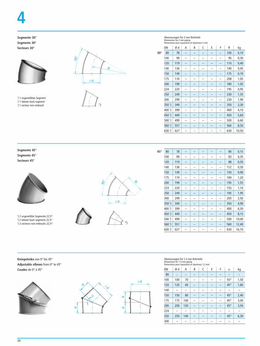
34
4
80 78 – – – – – 100 0,10
100 99 – – – – – 95 0,30
120 119 – – – – – 110 0,40
140 136 – – – – – 140 0,45
150 149 – – – – – 175 0,70
175 174 – – – – – 208 1,05
200 199 – – – – – 180 1,05
224 220 – – – – – 195 0,95
250 249 – – – – – 230 1,55
300 299 – – – – – 230 1,90
350 1) 349 – – – – – 350 3,30
400 1) 399 – – – – – 400 4,10
450 1) 449 – – – – – 450 5,60
500 1) 499 – – – – – 500 6,60
560 1) 557 – – – – – 560 8,50
630 1) 627 – – – – – 630 10,50
Abmessungen für 2 mm RohrteileDimensions for 2 mm pipingDimensions pour tuyauterie en épaisseur 2 mm
DN Ø d A B C E F R kg
30°
1) 1 ungewölbtes Segment1) 1 lobster back segment1) 1 secteur non embouti
Segmente 30°
Segments 30°
Secteurs 30°
Kniegelenke von 0° bis 45°
Adjustable elbows from 0° to 45°
Coudes de 0° à 45°
d
R
30°
2) 2 ungewölbte Segmente 22,5°2) 2 lobster back segments 22,5°2) 2 secteurs non emboutis 22,5°
Segmente 45°
Segments 45°
Secteurs 45°
d
R
45°
AA
d
a
A
A d
80 78 – – – – – 80 0,15
100 99 – – – – – 83 0,35
120 119 – – – – – 88 0,50
140 136 – – – – – 112 0,50
150 149 – – – – – 150 0,90
175 174 – – – – – 160 1,20
200 199 – – – – – 195 1,55
224 220 – – – – – 155 1,10
250 249 – – – – – 195 1,95
300 299 – – – – – 205 2,50
350 2) 349 – – – – – 350 4,90
400 2) 399 – – – – – 400 6,50
450 2) 449 – – – – – 450 8,15
500 2) 499 – – – – – 500 10,00
560 2) 557 – – – – – 560 12,40
630 2) 627 – – – – – 630 16,10
45°
80 – – – – – – – –
100 100 70 – – – – 55° 1,50
120 120 60 – – – – 45° 1,60
140 – – – – – – – –
150 150 80 – – – – 45° 2,40
175 175 100 – – – – 45° 3,00
200 200 120 – – – – 45° 3,50
224 – – – – – – – –
250 250 140 – – – – 45° 6,30
300 – – – – – – – –
Abmessungen für 1,5 mm RohrteileDimensions for 1.5 mm pipingDimensions pour tuyauterie en épaisseur 1,5 mm
DN Ø d A B C E F B kg
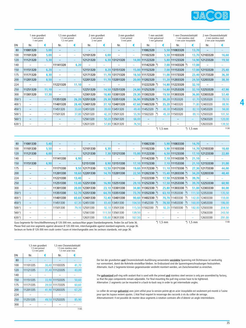
35
4
1 mm grundiert 1,5 mm grundiert 2 mm grundiert 3 mm grundiert 1 mm verzinkt 1 mm Chromnickelstahl 2 mm Chromnickelstahl1 mm primed 1.5 mm primed 2 mm primed 3 mm primed 1 mm galvanized 1 mm stainless steel 2 mm stainless steel1 mm peint 1,5 mm peint 2 mm peint 3 mm peint 1 mm galvanisé 1 mm acier inoxydable 2 mm acier inoxydable
11081320 5,00
11101320 5,00
11121320 5,30
– –
11151320 6,20
11171320 8,30
11201320 8,50
– –
11251320 11,10
11301320 17,30
– –
– –
– –
– –
– –
– –
– –
– –
– –
11141320 6,20
– –
– –
– –
11221320 11,10
– –
– –
11351320 26,20
11401320 28,40
11451320 33,60
11501320 37,80
– –
– –
– –
12101320 6,00
12121320 6,30
– –
12151320 8,20
12171320 11,70
12201320 11,70
– –
12251320 14,50
12301320 18,80
12351320 29,30
12401320 37,10
12451320 39,00
12501320 42,30
12561320 50,20
12631320 57,80
– –
– –
13121320 14,00
– –
13151320 15,00
13171320 18,50
13201320 20,00
– –
13251320 24,80
13301320 29,30
13351320 36,90
13401320 47,60
13451320 49,40
13501320 55,90
13561320 66,00
13631320 76,50
11082320 5,50
11102320 5,50
11122320 5,80
11142320 *) 7,00
11152320 7,00
11172320 11,00
11202320 11,20
11222320 *) 14,80
11252320 14,80
11302320 19,50
11352320 *) 30,20
11402320 *) 35,20
11452320 *) 40,30
11502320 *) 45,30
– –
– –
11083320 13,70
11103320 13,70
11123320 14,90
11143320 *) 17,00
11153320 17,00
11173320 23,40
11203320 24,50
11223320 32,10
11253320 32,10
11303320 36,80
11353320 61,70
11403320 71,80
11453320 82,10
11503320 89,10
– –
– –
– –
12103320 16,60
12123320 19,50
– –
12153320 25,40
12173320 36,30
12203320 38,30
– –
12253320 47,90
12303320 57,40
12353320 70,10
12403320 88,90
12453320 94,00
12503320 101,50
12563320 120,00
12633320 139,50
Nr. € Nr. € Nr. € Nr. € Nr. € Nr. € Nr. €DN
1130
80
100
120
140
150
175
200
224
250
300
350 1)
400 1)
450 1)
500 1)
560 1)
630 1)
*) 1,5 mm *) 1,5 mm
1140
11081330 5,40
11101330 5,50
11121330 6,00
– –
11151330 6,90
– –
– –
– –
– –
– –
– –
– –
– –
– –
– –
– –
– –
– –
– –
11141330 6,90
– –
11171330 9,50
11201330 10,60
11221330 13,40
11251330 13,40
11301330 20,00
11351330 52,70
11401330 60,60
11451330 67,30
11501330 79,10
– –
– –
– –
12101330 6,30
12121330 7,30
– –
12151330 8,90
12171330 12,50
12201330 14,70
– –
12251330 16,90
12301330 23,10
12351330 64,70
12401330 72,40
12451330 83,40
12501330 92,10
12561330 111,50
12631330 135,00
– –
– –
13121330 15,00
– –
13151330 17,10
13171330 19,60
13201330 22,50
– –
13251330 29,10
13301330 34,80
13351330 73,70
13401330 90,60
13451330 104,50
13501330 115,50
13561330 139,50
13631330 167,50
11082330 5,90
11102330 5,90
11122330 6,50
11142330 *) 7,10
11152330 7,10
11172330 *) 11,10
11202330 *) 15,40
11222330 *) 17,50
11252330 *) 17,50
11302330 *) 25,80
11352330 *) 63,10
11402330 *) 70,70
11452330 *) 78,50
11502330 *) 92,20
– –
– –
11083330 14,70
11103330 14,70
11123330 17,10
11143330 *) 21,10
11153330 21,10
11173330 *) 27,30
11203330 *) 34,20
11223330 *) 39,70
11253330 *) 39,70
11303330 *) 51,00
11353330 *) 111,50
11403330 *) 142,00
11453330 *) 160,00
11503330 *) 182,00
– –
– –
– –
12103330 18,60
12123330 22,80
– –
12153330 31,00
12173330 44,00
12203330 48,40
– –
12253330 60,90
12303330 84,00
12353330 135,50
12403330 159,00
12453330 186,00
12503330 204,50
12563330 243,50
12633330 291,00
80
100
120
140
150
175
200
224
250
300
350 2)
400 2)
450 2)
500 2)
560 2)
630 2)
*) 1,5 mm *) 1,5 mm
1,5 mm grundiert1.5 mm primed1,5 mm peint
1,5 mm Chromnickelstahl1.5 mm stainless steel
1,5 mm acier inox
Nr. € Nr. €DN
1145
80
100
120
140
150
175
200
224
250
300
– –
11101335 30,40
11121335 31,40
– –
11151335 33,90
11171335 39,50
11201335 41,90
– –
11251335 49,50
– –
– –
11103335 41,70
11123335 43,00
– –
11153335 50,60
11173335 60,60
11203335 67,20
– –
11253335 85,90
– –
Der bei der grundierten und Chromnickelstahl-Ausführung verwendete verzinkte Spannring mit Dichtmasse ist werkseitig nur vormontiert, damit die Rohrteile einstellbar bleiben. Im Endzustand sind die Spannringverschraubungen festzuziehen.Alternativ: Auch 2 Segmente können gegeneinander verdreht montiert werden, um Zwischenwinkel zu erreichen.
The galvanized pull-ring with sealant that is used with the primed and stainless steel version is only pre-assembled by factory, so that the pipe components remain adjustable. For final mounting the pull ring screws have to be tightened.Alternative: 2 segments can be mounted in a back-to-back way in order to get intermediate angles.
Le collier de serrage galvanisé avec joint utilisé pour la version peinte et en acier inoxydable est seulement pré-monté à l'usinepour que les tuyaux restent ajustes. L'état final requiert le resserrage des raccords à vis du collier de serrage. Alternativement: Il est possible de monter deux segments à rotation contraire afin d'obtenir un angle intermédiaire.
Guss-Segmente für Verschleißhemmung Ø 120-300 mm, austauschbar gegen Standardsegmente, finden Sie auf Seite 36.Please find cast-iron segments against abrasion Ø 120-300 mm, interchangeable against standard-segments, on page 36.Secteurs en fonte Ø 120-300 mm coulé contre l’usure et interchangeable avec les secteurs standards, voir page 36.
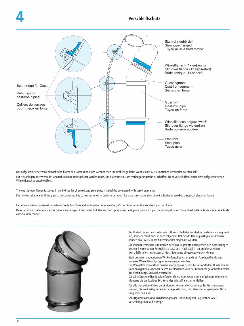
36
4
Spannringe für Guss
Pull-rings for
cast-iron piping
Colliers de serrage
pour tuyaux en fonte
Winkelflansch angeschweißt
Slip-over flange welded-on
Bride cornière soudée
Stahlrohr gebördelt
Steel pipe flanged
Tuyau a a bord tombécier
Winkelflansch (1x getrennt)
Slip-over flange (1x separated)
Bride conique (1x séparé)
Gussrohr
Cast-iron pipe
Tuyau en fonte
Stahlrohr
Steel pipe
Tuyau acier
Gusssegment
Cast-iron segment
Secteur en fonte
Der aufgeschnittene Winkelflansch wird hinter den Bördelrand eines vorhandenen Stahlrohres gedreht, wenn es mit Guss-Rohrteilen verbunden werden soll.
Für Neuanlagen oder wenn das anzuschließende Rohr gekürzt werden muss, um Platz für ein Guss-Verlängerungsrohr zu schaffen, ist es vorteilhafter, einen nicht aufgeschnittenenWinkelflansch anzuschweißen.
The cut slip-over flange is turned in behind the lip of an existing steel pipe, if it shall be connected with cast-iron piping.
For new installations or if the pipe to be connected has to be shortened in order to get room for a cast-iron extension pipe it is better to weld on a non-cut slip-over flange.
La bride cornière coupée est tournée contre le bord tombé d'un tuyau en acier existant, s'il doit être raccordé avec des tuyaux en fonte.
Dans le cas d'installations neuves ou lorsque le tuyau à raccorder doit être raccourci pour créer de la place pour un tuyau de prolongation en fonte, il est préférable de souder une bridecornière non coupée.
Bei Umlenkungen des Förderguts tritt Verschleiß der Rohrleitung nicht nur im Segmentauf, sondern meist auch in dem folgenden Rohrstück. Bei ungünstigen Situationenkönnen zwei Guss-Rohre hintereinander eingebaut werden.
Die Innendurchmesser und Radien der Guss-Segmente entsprechen den Abmessungenunserer 3 mm starken Rohrteile, so dass auch nachträglich an problematischenVerschleißstellen im Austausch Guss-Segmente eingesetzt werden können.
Statt des oben angegebenen Winkelflansches kann auch ein Anschweißende ausunserem Winkelflanschprogramm verwendet werden.Die Winkelflanschrohrteile passen übergangslos zu den Guss-Rohrteilen. Durch den amRohr anliegenden Schenkel des Winkelflansches wird der besonders gefährdete Bereichder Verbindungs-Stoßstelle verstärkt. Da keine Druckstoßfestigkeit erforderlich ist, kann wegen der einfacheren, schnellerenMontage die werkseitige Dichtung des Winkelflansches entfallen.
Für alle hier aufgeführten Verbindungen können die Spannringe für Guss eingesetztwerden, die werkseitig mit einer dauerplastischen, für Lebensmittel geeignete, Dich-tung versehen sind.
Schüttgutbremsen und Auskleidungen der Rohrleitung mit Polyurethan oderVerschleißgummi auf Anfrage.
Verschleißschutz
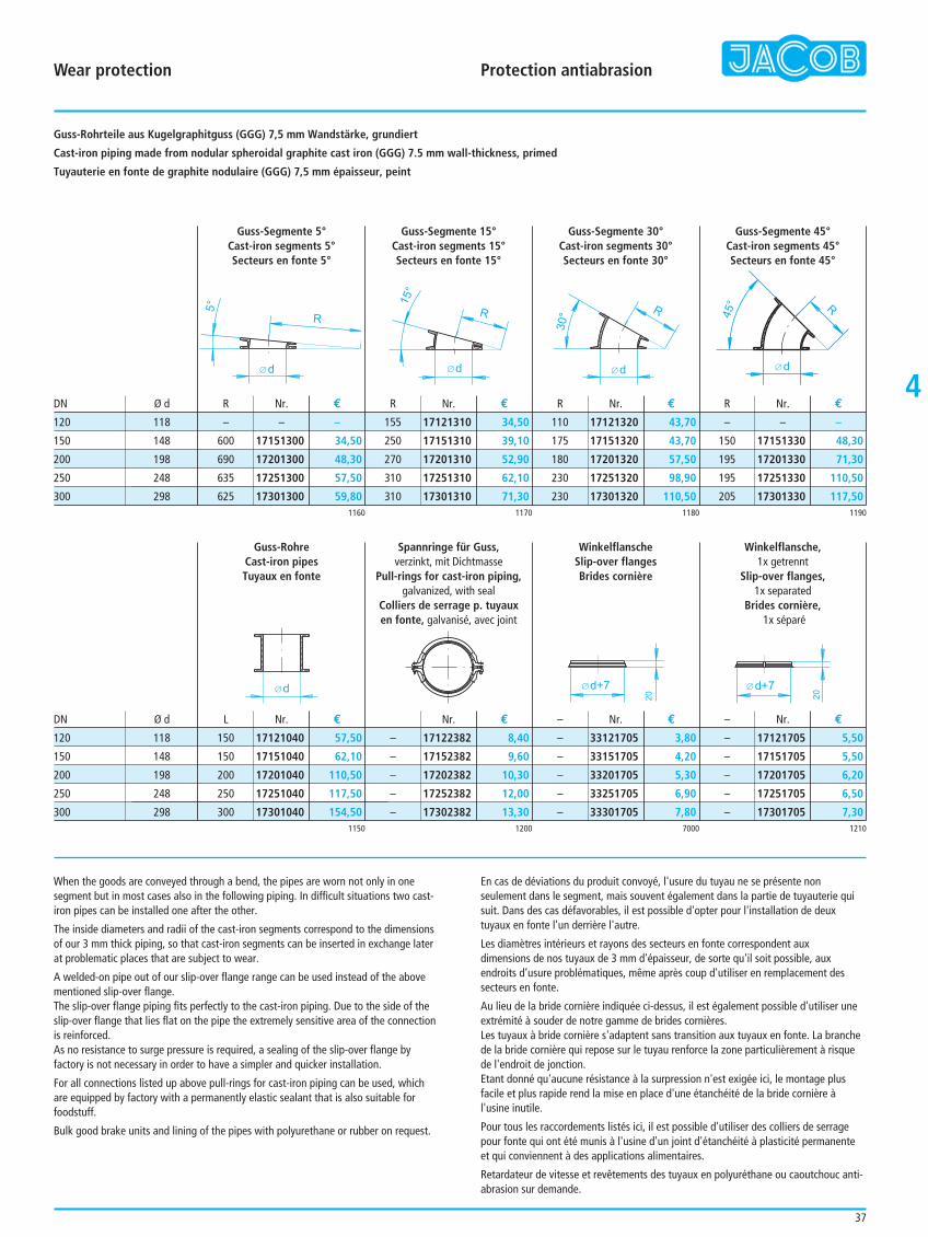
d
5°
R
d
15°
R
d
30°
R 45° R
d
37
4
When the goods are conveyed through a bend, the pipes are worn not only in onesegment but in most cases also in the following piping. In difficult situations two cast-iron pipes can be installed one after the other.
The inside diameters and radii of the cast-iron segments correspond to the dimensionsof our 3 mm thick piping, so that cast-iron segments can be inserted in exchange laterat problematic places that are subject to wear.
A welded-on pipe out of our slip-over flange range can be used instead of the abovementioned slip-over flange.The slip-over flange piping fits perfectly to the cast-iron piping. Due to the side of theslip-over flange that lies flat on the pipe the extremely sensitive area of the connectionis reinforced.As no resistance to surge pressure is required, a sealing of the slip-over flange byfactory is not necessary in order to have a simpler and quicker installation.
For all connections listed up above pull-rings for cast-iron piping can be used, whichare equipped by factory with a permanently elastic sealant that is also suitable forfoodstuff.
Bulk good brake units and lining of the pipes with polyurethane or rubber on request.
En cas de déviations du produit convoyé, l'usure du tuyau ne se présente nonseulement dans le segment, mais souvent également dans la partie de tuyauterie quisuit. Dans des cas défavorables, il est possible d'opter pour l'installation de deuxtuyaux en fonte l'un derrière l'autre.
Les diamètres intérieurs et rayons des secteurs en fonte correspondent aux dimensions de nos tuyaux de 3 mm d'épaisseur, de sorte qu'il soit possible, auxendroits d’usure problématiques, même après coup d'utiliser en remplacement dessecteurs en fonte.
Au lieu de la bride cornière indiquée ci-dessus, il est également possible d'utiliser uneextrémité à souder de notre gamme de brides cornières.Les tuyaux à bride cornière s'adaptent sans transition aux tuyaux en fonte. La branchede la bride cornière qui repose sur le tuyau renforce la zone particulièrement à risquede l'endroit de jonction.Etant donné qu'aucune résistance à la surpression n'est exigée ici, le montage plusfacile et plus rapide rend la mise en place d'une étanchéité de la bride cornière àl'usine inutile.
Pour tous les raccordements listés ici, il est possible d'utiliser des colliers de serragepour fonte qui ont été munis à l'usine d'un joint d'étanchéité à plasticité permanenteet qui conviennent à des applications alimentaires.
Retardateur de vitesse et revêtements des tuyaux en polyuréthane ou caoutchouc anti-abrasion sur demande.
Guss-Rohrteile aus Kugelgraphitguss (GGG) 7,5 mm Wandstärke, grundiert
Cast-iron piping made from nodular spheroidal graphite cast iron (GGG) 7.5 mm wall-thickness, primed
Tuyauterie en fonte de graphite nodulaire (GGG) 7,5 mm épaisseur, peint
Guss-Segmente 5°Cast-iron segments 5°Secteurs en fonte 5°
Guss-Segmente 15°Cast-iron segments 15°Secteurs en fonte 15°
Guss-Segmente 30°Cast-iron segments 30°Secteurs en fonte 30°
Guss-Segmente 45°Cast-iron segments 45°Secteurs en fonte 45°
Nr. € R R RDN Ø d
1160 1170 1180 1190
120 118
150 148
200 198
250 248
300 298
155
250
270
310
310
R
–
600
690
635
625
110
175
180
230
230
–
150
195
195
205
Nr. €
17121310 34,50
17151310 39,10
17201310 52,90
17251310 62,10
17301310 71,30
– –
17151300 34,50
17201300 48,30
17251300 57,50
17301300 59,80
17121320 43,70
17151320 43,70
17201320 57,50
17251320 98,90
17301320 110,50
– –
17151330 48,30
17201330 71,30
17251330 110,50
17301330 117,50
Nr. € Nr. €
d
20
d+7
20
d+7
Guss-RohreCast-iron pipesTuyaux en fonte
Spannringe für Guss,verzinkt, mit Dichtmasse
Pull-rings for cast-iron piping,galvanized, with seal
Colliers de serrage p. tuyaux en fonte, galvanisé, avec joint
WinkelflanscheSlip-over flangesBrides cornière
Winkelflansche,1x getrennt
Slip-over flanges,1x separated
Brides cornière,1x séparé
Nr. € – –
1150 1200 7000 1210
–
–
–
–
–
–
–
–
–
–
–
–
–
–
–
Nr. €
17122382 8,40
17152382 9,60
17202382 10,30
17252382 12,00
17302382 13,30
17121040 57,50
17151040 62,10
17201040 110,50
17251040 117,50
17301040 154,50
33121705 3,80
33151705 4,20
33201705 5,30
33251705 6,90
33301705 7,80
17121705 5,50
17151705 5,50
17201705 6,20
17251705 6,50
17301705 7,30
Nr. € Nr. €DN Ø d
120 118
150 148
200 198
250 248
300 298
L
150
150
200
250
300
Wear protection Protection antiabrasion
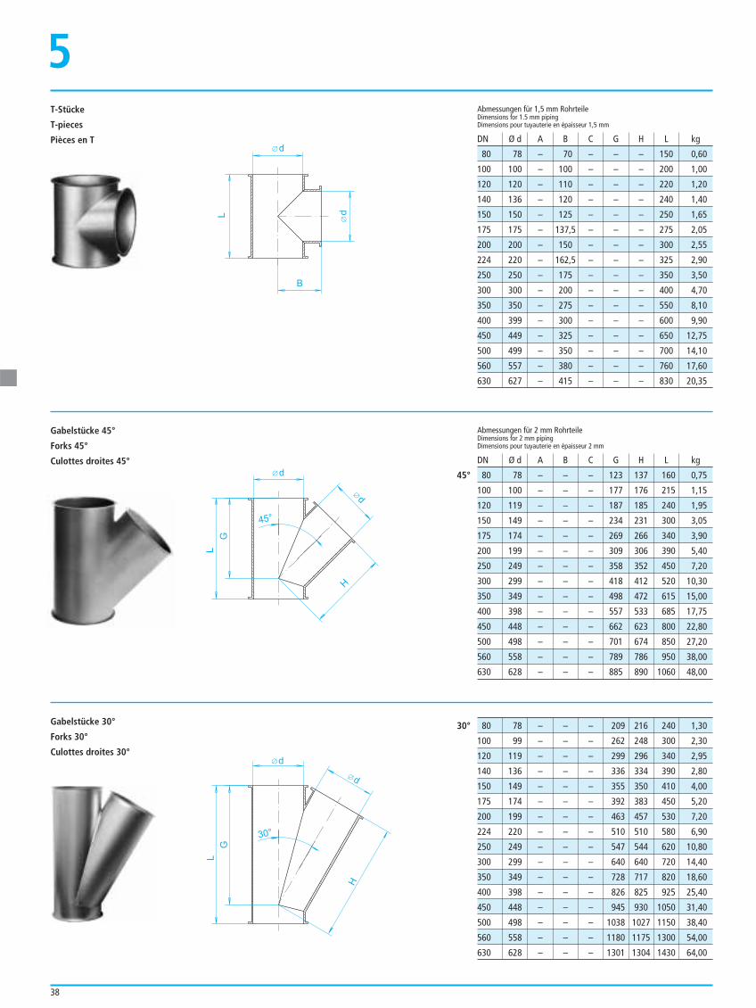
38
80 78 – 70 – – – 150 0,60
100 100 – 100 – – – 200 1,00
120 120 – 110 – – – 220 1,20
140 136 – 120 – – – 240 1,40
150 150 – 125 – – – 250 1,65
175 175 – 137,5 – – – 275 2,05
200 200 – 150 – – – 300 2,55
224 220 – 162,5 – – – 325 2,90
250 250 – 175 – – – 350 3,50
300 300 – 200 – – – 400 4,70
350 350 – 275 – – – 550 8,10
400 399 – 300 – – – 600 9,90
450 449 – 325 – – – 650 12,75
500 499 – 350 – – – 700 14,10
560 557 – 380 – – – 760 17,60
630 627 – 415 – – – 830 20,35
Abmessungen für 1,5 mm RohrteileDimensions for 1.5 mm pipingDimensions pour tuyauterie en épaisseur 1,5 mm
Abmessungen für 2 mm RohrteileDimensions for 2 mm pipingDimensions pour tuyauterie en épaisseur 2 mm
DN Ø d A B C G H L kg
DN Ø d A B C G H L kg
80 78 – – – 123 137 160 0,75
100 100 – – – 177 176 215 1,15
120 119 – – – 187 185 240 1,95
150 149 – – – 234 231 300 3,05
175 174 – – – 269 266 340 3,90
200 199 – – – 309 306 390 5,40
250 249 – – – 358 352 450 7,20
300 299 – – – 418 412 520 10,30
350 349 – – – 498 472 615 15,00
400 398 – – – 557 533 685 17,75
450 448 – – – 662 623 800 22,80
500 498 – – – 701 674 850 27,20
560 558 – – – 789 786 950 38,00
630 628 – – – 885 890 1060 48,00
80 78 – – – 209 216 240 1,30
100 99 – – – 262 248 300 2,30
120 119 – – – 299 296 340 2,95
140 136 – – – 336 334 390 2,80
150 149 – – – 355 350 410 4,00
175 174 – – – 392 383 450 5,20
200 199 – – – 463 457 530 7,20
224 220 – – – 510 510 580 6,90
250 249 – – – 547 544 620 10,80
300 299 – – – 640 640 720 14,40
350 349 – – – 728 717 820 18,60
400 398 – – – 826 825 925 25,40
450 448 – – – 945 930 1050 31,40
500 498 – – – 1038 1027 1150 38,40
560 558 – – – 1180 1175 1300 54,00
630 628 – – – 1301 1304 1430 64,00
45°
30°
d
d
B
L
d
d
H
L
G
45°
d
d
H
L
G
30°
T-Stücke
T-pieces
Pièces en T
5
Gabelstücke 45°
Forks 45°
Culottes droites 45°
Gabelstücke 30°
Forks 30°
Culottes droites 30°
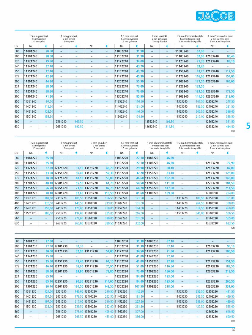
39
1,5 mm grundiert 2 mm grundiert 1,5 mm verzinkt 2 mm verzinkt 1,5 mm Chromnickelstahl 2 mm Chromnickelstahl1.5 mm primed 2 mm primed 1.5 mm galvanized 2 mm galvanized 1.5 mm stainless steel 2 mm stainless steel1,5 mm peint 2 mm peint 1,5 mm galvanisé 2 mm galvanisé 1,5 mm acier inoxydable 2 mm acier inoxydable
1,5 mm grundiert 2 mm grundiert 3 mm grundiert 1,5 mm verzinkt 1 mm Chromnickelstahl 1,5 mm Chromnickelstahl 2 mm Chromnickelstahl1.5 mm primed 2 mm primed 3 mm primed 1.5 mm galvanized 1 mm stainless steel 1.5 mm stainless steel 2 mm stainless steel1,5 mm peint 2 mm peint 3 mm peint 1,5 mm galvanisé 1 mm acier inoxydable 1,5 mm acier inoxydable 2 mm acier inoxydable
11081240 28,50
11101240 28,50
11121240 29,90
11141240 37,40
11151240 37,40
11171240 42,20
11201240 44,90
11221240 58,60
11251240 58,60
11301240 71,20
11351240 97,50
11401240 115,50
11451240 128,50
11501240 153,50
– –
– –
– –
– –
– –
– –
– –
– –
– –
– –
– –
– –
– –
– –
– –
– –
12561240 169,50
12631240 192,50
– –
– –
– –
– –
– –
– –
– –
– –
– –
– –
– –
– –
– –
– –
– –
– –
11082240 31,90
11102240 31,90
11122240 34,00
11142240 43,70
11152240 43,70
11172240 45,90
11202240 55,90
11222240 73,00
11252240 73,00
11302240 85,90
11352240 110,50
11402240 131,00
11452240 146,00
11502240 174,50
– –
– –
– –
– –
– –
– –
– –
– –
– –
– –
– –
– –
– –
– –
– –
– –
12562240 192,50
12632240 214,50
11083240 67,90
11103240 67,90
11123240 71,30
11143240 83,20
11153240 83,20
11173240 116,00
11203240 123,50
11223240 133,50
11253240 133,50
11303240 141,50
11353240 167,50
11403240 183,50
11453240 200,50
11503240 217,00
– –
– –
– –
12103240 83,40
12123240 89,10
– –
12153240 117,50
12173240 154,00
12203240 165,00
– –
12253240 173,50
12303240 212,00
12353240 248,50
12403240 281,50
12453240 316,00
12503240 358,50
12563240 381,50
12633240 414,50
Nr. € Nr. € Nr. € Nr. € Nr. € Nr. € Nr. €
Nr. € Nr. € Nr. € Nr. € Nr. € Nr. € Nr. €
DN
DN
1070
80
100
120
140
150
175
200
224
250
300
350
400
450
500
560
630
1050
11081220 25,30
11101220 25,30
11121220 27,30
11151220 33,00
11171220 38,90
11201220 48,40
11251220 56,70
11301220 70,40
11351220 101,00
11401220 128,50
11451220 159,00
11501220 186,50
– –
– –
– –
– –
12121220 31,10
12151220 36,40
12171220 48,10
12201220 55,50
12251220 73,90
12301220 92,60
12351220 109,50
12401220 149,50
12451220 176,00
12501220 194,00
12561220 224,00
12631220 265,00
– –
– –
13121220 45,70
13151220 52,30
13171220 58,00
13201220 61,70
13251220 87,70
13301220 115,50
13351220 156,50
13401220 219,00
13451220 258,00
13501220 285,00
13561220 330,00
13631220 389,50
11082220 27,10
11102220 27,10
11122220 29,90
11152220 37,20
11172220 46,60
11202220 54,50
11252220 64,70
11302220 81,60
11352220 121,50
11402220 151,00
11452220 184,00
11502220 216,00
11562220 251,00
11632220 302,00
11083220 46,30
11103220 46,30
11123220 60,10
11153220 83,40
11173220 102,50
11203220 111,50
11253220 147,50
11303220 169,50
– –
– –
– –
– –
– –
– –
– –
– –
– –
– –
– –
– –
– –
– –
11353220 188,50
11403220 264,50
11453220 314,50
11503220 345,00
– –
– –
– –
12103220 72,90
12123220 87,00
12153220 125,00
12173220 145,00
12203220 184,50
12253220 214,50
12303220 294,00
12353220 351,00
12403220 388,00
12453220 450,00
12503220 506,50
12563220 565,00
12633220 623,50
80
100
120
150
175
200
250
300
350
400
450
500
560
630
1060
11081230 27,30
11101230 27,30
11121230 30,00
11141230 35,60
11151230 35,60
11171230 46,70
11201230 58,60
11221230 65,10
11251230 65,10
11301230 80,70
11351230 121,00
11401230 157,50
11451230 197,00
11501230 235,00
– –
– –
– –
12101230 30,30
12121230 32,90
– –
12151230 43,40
12171230 56,00
12201230 69,90
– –
12251230 90,30
12301230 130,50
12351230 143,00
12401230 178,50
12451230 217,00
12501230 239,50
12561230 275,00
12631230 293,50
– –
– –
13121230 54,00
– –
13151230 64,10
13171230 70,90
13201230 79,80
– –
13251230 114,00
13301230 143,50
13351230 210,50
13401230 262,50
13451230 319,50
13501230 352,00
13561230 405,00
13631230 433,00
11082230 31,30
11102230 31,30
11122230 34,50
11142230 41,00
11152230 41,00
11172230 51,00
11202230 72,40
11222230 84,40
11252230 84,40
11302230 107,50
11352230 142,50
11402230 181,50
11452230 223,50
11502230 261,50
11562230 307,00
11632230 336,00
11083230 57,10
11103230 57,10
11123230 71,90
11143230 97,20
11153230 97,20
11173230 116,50
11203230 156,00
11223230 183,00
11253230 183,00
11303230 218,00
– –
– –
– –
– –
– –
– –
– –
– –
– –
– –
– –
– –
– –
– –
– –
– –
11353230 255,50
11403230 285,50
11453230 388,00
11503230 427,50
– –
– –
– –
12103230 93,10
12123230 106,50
– –
12153230 151,50
12173230 188,50
12203230 219,50
– –
12253230 260,50
12303230 331,00
12353230 431,50
12403230 459,50
12453230 489,00
12503230 565,00
12563230 648,50
12633230 690,50
80
100
120
140
150
175
200
224
250
300
350
400
450
500
560
630
5
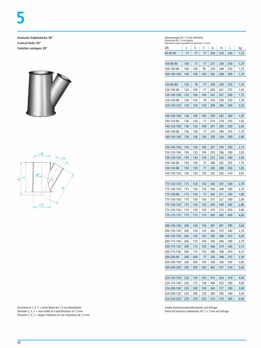
40
E
H
L
G
30°
F
C
Konische Gabelstücke 30°
Conical forks 30°
Culottes coniques 30°
5
80-80-80 77 77 77 209 216 240 1,32
100-80-80 100 77 77 237 236 250 1,25
100-100-80 100 100 78 239 248 250 1,35
100-100-100 100 100 100 262 248 300 1,70
120-80-80 120 78 77 258 259 255 1,35
120-100-80 120 100 77 260 261 255 1,45
120-100-100 120 100 100 267 267 290 1,75
120-120-80 120 120 78 256 258 250 1,50
120-120-120 120 120 120 299 296 340 2,20
140-100-100 136 100 100 290 292 300 1,95
140-120-80 136 120 77 274 278 255 1,65
140-120-100 136 120 100 291 293 300 2,00
140-140-80 136 136 77 275 284 255 1,70
140-140-140 136 136 136 336 334 390 2,80
150-100-100 150 100 100 291 294 290 2,10
150-120-100 150 120 100 293 296 290 2,05
150-120-120 150 120 120 323 324 340 2,45
150-140-80 150 136 77 286 292 255 1,75
150-150-80 150 150 77 282 288 250 1,85
150-150-150 150 150 150 355 350 410 3,05
175-120-120 175 120 120 343 347 340 2,70
175-140-120 175 136 120 344 348 340 2,70
175-150-80 175 150 77 302 311 250 1,90
175-150-100 175 150 100 315 321 290 2,40
175-150-120 175 150 120 345 349 340 2,80
175-150-150 175 150 150 375 373 410 3,80
175-175-175 175 175 175 392 383 450 4,00
200-140-140 200 136 136 387 401 390 3,60
200-150-120 200 150 120 365 373 340 2,70
200-150-150 200 150 150 395 396 410 5,00
200-175-100 200 175 100 336 346 290 2,70
200-175-120 200 175 120 366 374 340 3,10
200-175-150 200 175 150 396 398 410 4,10
200-200-80 200 200 77 330 348 255 2,50
200-200-100 200 200 100 348 358 300 3,00
200-200-200 200 200 200 463 457 530 5,60
224-150-150 220 150 150 410 424 410 4,00
224-175-140 220 175 136 406 423 390 4,00
224-200-100 220 200 100 364 377 300 3,00
224-200-120 220 200 120 384 395 340 3,30
224-224-224 220 220 220 510 510 580 6,90
Abmessungen für 1,5 mm RohrteileDimensions for 1.5 mm pipingDimensions pour tuyauterie en épaisseur 1,5 mm
DN C E F G H L kg
Andere Durchmesserkombinationen auf Anfrage.Preise für konische Gabelstücke 30° 2 + 3 mm auf Anfrage.
Durchmesser C, E, F = lichte Weite bei 1,5 mm WandstärkeDiameter C, E, F = clear width at a wall thickness of 1.5 mmDiamètre C, E, F = largeur intérieure en cas d'épaisseur de 1,5 mm
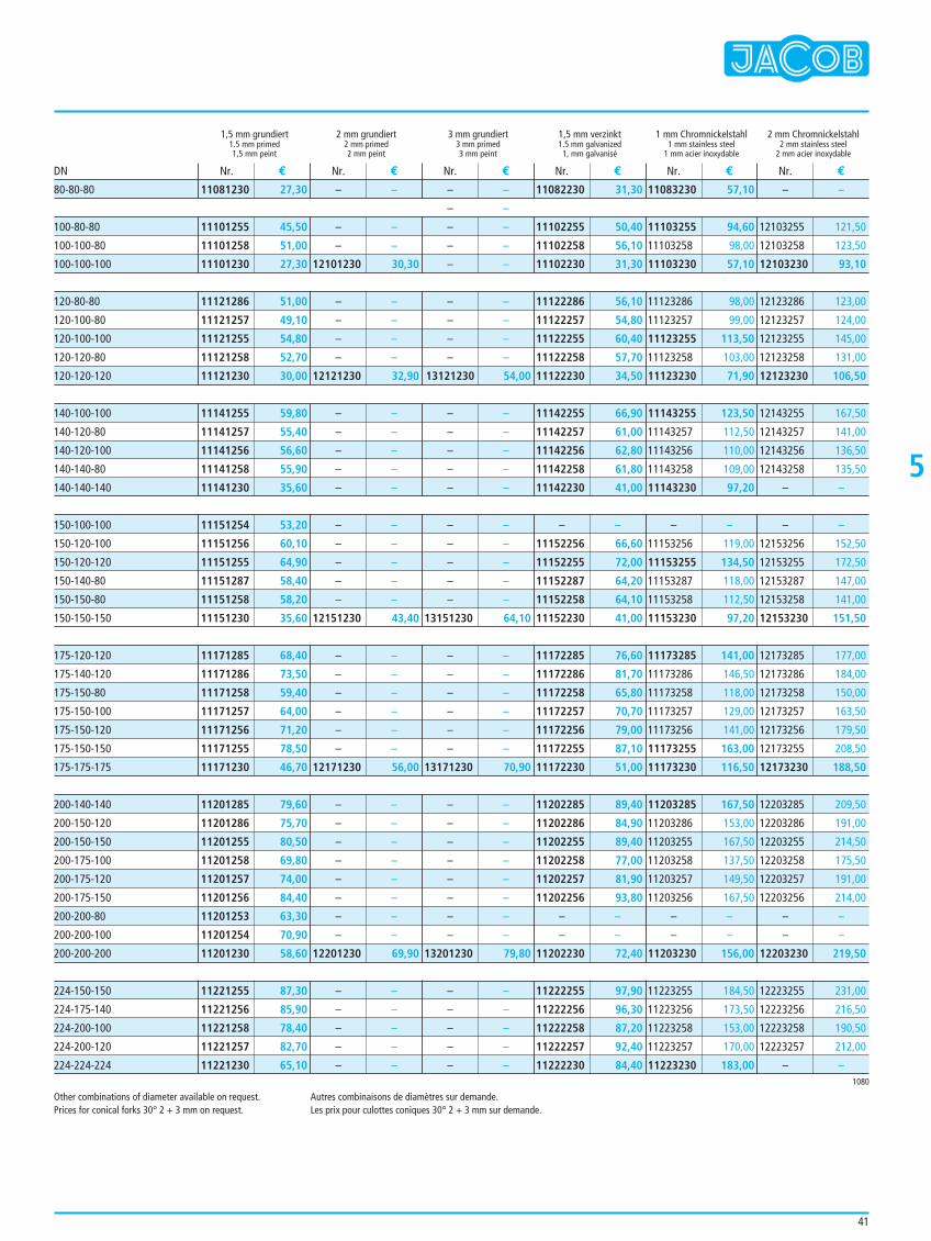
41
5
Other combinations of diameter available on request.Prices for conical forks 30° 2 + 3 mm on request.
Autres combinaisons de diamètres sur demande.Les prix pour culottes coniques 30° 2 + 3 mm sur demande.
1,5 mm grundiert 2 mm grundiert 3 mm grundiert 1,5 mm verzinkt 1 mm Chromnickelstahl 2 mm Chromnickelstahl1.5 mm primed 2 mm primed 3 mm primed 1.5 mm galvanized 1 mm stainless steel 2 mm stainless steel1,5 mm peint 2 mm peint 3 mm peint 1, mm galvanisé 1 mm acier inoxydable 2 mm acier inoxydable
11081230 27,30
11101255 45,50
11101258 51,00
11101230 27,30
11121286 51,00
11121257 49,10
11121255 54,80
11121258 52,70
11121230 30,00
11141255 59,80
11141257 55,40
11141256 56,60
11141258 55,90
11141230 35,60
11151254 53,20
11151256 60,10
11151255 64,90
11151287 58,40
11151258 58,20
11151230 35,60
11171285 68,40
11171286 73,50
11171258 59,40
11171257 64,00
11171256 71,20
11171255 78,50
11171230 46,70
11201285 79,60
11201286 75,70
11201255 80,50
11201258 69,80
11201257 74,00
11201256 84,40
11201253 63,30
11201254 70,90
11201230 58,60
11221255 87,30
11221256 85,90
11221258 78,40
11221257 82,70
11221230 65,10
– –
– –
– –
12101230 30,30
– –
– –
– –
– –
12121230 32,90
– –
– –
– –
– –
– –
– –
– –
– –
– –
– –
12151230 43,40
– –
– –
– –
– –
– –
– –
12171230 56,00
– –
– –
– –
– –
– –
– –
– –
– –
12201230 69,90
– –
– –
– –
– –
– –
– –
– –
– –
– –
– –
– –
– –
– –
– –
13121230 54,00
– –
– –
– –
– –
– –
– –
– –
– –
– –
– –
13151230 64,10
– –
– –
– –
– –
– –
– –
13171230 70,90
– –
– –
– –
– –
– –
– –
– –
– –
13201230 79,80
– –
– –
– –
– –
– –
11082230 31,30
11102255 50,40
11102258 56,10
11102230 31,30
11122286 56,10
11122257 54,80
11122255 60,40
11122258 57,70
11122230 34,50
11142255 66,90
11142257 61,00
11142256 62,80
11142258 61,80
11142230 41,00
– –
11152256 66,60
11152255 72,00
11152287 64,20
11152258 64,10
11152230 41,00
11172285 76,60
11172286 81,70
11172258 65,80
11172257 70,70
11172256 79,00
11172255 87,10
11172230 51,00
11202285 89,40
11202286 84,90
11202255 89,40
11202258 77,00
11202257 81,90
11202256 93,80
– –
– –
11202230 72,40
11222255 97,90
11222256 96,30
11222258 87,20
11222257 92,40
11222230 84,40
11083230 57,10
11103255 94,60
11103258 98,00
11103230 57,10
11123286 98,00
11123257 99,00
11123255 113,50
11123258 103,00
11123230 71,90
11143255 123,50
11143257 112,50
11143256 110,00
11143258 109,00
11143230 97,20
– –
11153256 119,00
11153255 134,50
11153287 118,00
11153258 112,50
11153230 97,20
11173285 141,00
11173286 146,50
11173258 118,00
11173257 129,00
11173256 141,00
11173255 163,00
11173230 116,50
11203285 167,50
11203286 153,00
11203255 167,50
11203258 137,50
11203257 149,50
11203256 167,50
– –
– –
11203230 156,00
11223255 184,50
11223256 173,50
11223258 153,00
11223257 170,00
11223230 183,00
– –
12103255 121,50
12103258 123,50
12103230 93,10
12123286 123,00
12123257 124,00
12123255 145,00
12123258 131,00
12123230 106,50
12143255 167,50
12143257 141,00
12143256 136,50
12143258 135,50
– –
– –
12153256 152,50
12153255 172,50
12153287 147,00
12153258 141,00
12153230 151,50
12173285 177,00
12173286 184,00
12173258 150,00
12173257 163,50
12173256 179,50
12173255 208,50
12173230 188,50
12203285 209,50
12203286 191,00
12203255 214,50
12203258 175,50
12203257 191,00
12203256 214,00
– –
– –
12203230 219,50
12223255 231,00
12223256 216,50
12223258 190,50
12223257 212,00
– –
Nr. € Nr. € Nr. € Nr. € Nr. € Nr. €DN
1080
80-80-80
100-80-80
100-100-80
100-100-100
120-80-80
120-100-80
120-100-100
120-120-80
120-120-120
140-100-100
140-120-80
140-120-100
140-140-80
140-140-140
150-100-100
150-120-100
150-120-120
150-140-80
150-150-80
150-150-150
175-120-120
175-140-120
175-150-80
175-150-100
175-150-120
175-150-150
175-175-175
200-140-140
200-150-120
200-150-150
200-175-100
200-175-120
200-175-150
200-200-80
200-200-100
200-200-200
224-150-150
224-175-140
224-200-100
224-200-120
224-224-224
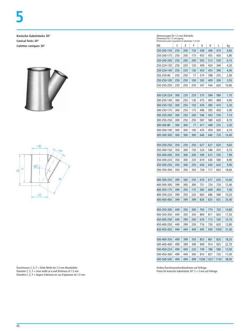
42
5
E
H
L
G
30°
F
C
Konische Gabelstücke 30°
Conical forks 30°
Culottes coniques 30°250-200-150 250 200 150 438 446 410 4,60
250-200-175 250 200 175 453 455 450 5,80
250-200-200 250 200 200 503 513 530 6,10
250-224-120 250 220 120 409 424 340 4,20
250-224-140 250 220 136 433 455 390 4,40
250-250-80 250 250 77 374 398 255 2,90
250-250-100 250 250 100 392 409 300 3,50
250-250-250 250 250 250 547 544 620 10,80
300-224-224 300 220 220 575 584 580 7,70
300-250-140 300 250 136 475 493 489 4,90
300-250-150 300 250 150 476 495 410 5,30
300-250-175 300 250 175 496 505 450 5,90
300-250-200 300 250 200 546 563 530 7,10
300-250-250 300 250 250 587 580 620 8,70
300-300-80 300 300 77 417 448 255 3,30
300-300-100 300 300 100 435 459 300 4,10
300-300-300 300 300 300 640 640 720 14,40
350-250-250 350 250 250 627 627 620 9,60
350-300-150 350 300 150 524 546 410 6,10
350-300-200 350 300 200 590 613 530 7,90
350-300-224 350 300 220 619 636 580 8,90
350-300-250 350 300 250 630 630 620 9,90
350-350-350 350 350 350 728 717 820 18,60
400-300-250 399 300 250 670 677 620 10,40
400-300-300 399 300 300 721 724 720 12,40
400-350-175 399 350 175 583 609 450 7,40
400-350-224 399 350 220 663 686 580 10,20
400-400-400 399 399 399 826 825 925 25,40
450-350-300 449 350 300 764 774 720 14,80
450-350-350 449 350 350 809 811 820 17,50
450-400-200 449 399 200 676 713 530 10,70
450-400-250 449 399 250 716 730 620 12,80
450-450-450 449 449 449 945 930 1050 31,40
500-400-350 499 399 350 853 861 820 18,20
500-400-400 499 399 399 909 914 925 22,70
500-450-224 499 449 220 749 786 580 13,00
500-450-300 499 449 300 810 827 720 17,00
500-500-500 499 499 499 1038 1027 1150 38,00
Abmessungen für 1,5 mm RohrteileDimensions for 1.5 mm pipingDimensions pour tuyauterie en épaisseur 1,5 mm
DN C E F G H L kg
Andere Durchmesserkombinationen auf Anfrage.Preise für konische Gabelstücke 30° 2 + 3 mm auf Anfrage.
Durchmesser C, E, F = lichte Weite bei 1,5 mm WandstärkeDiameter C, E, F = clear width at a wall thickness of 1.5 mmDiamètre C, E, F = largeur intérieure en cas d'épaisseur de 1,5 mm
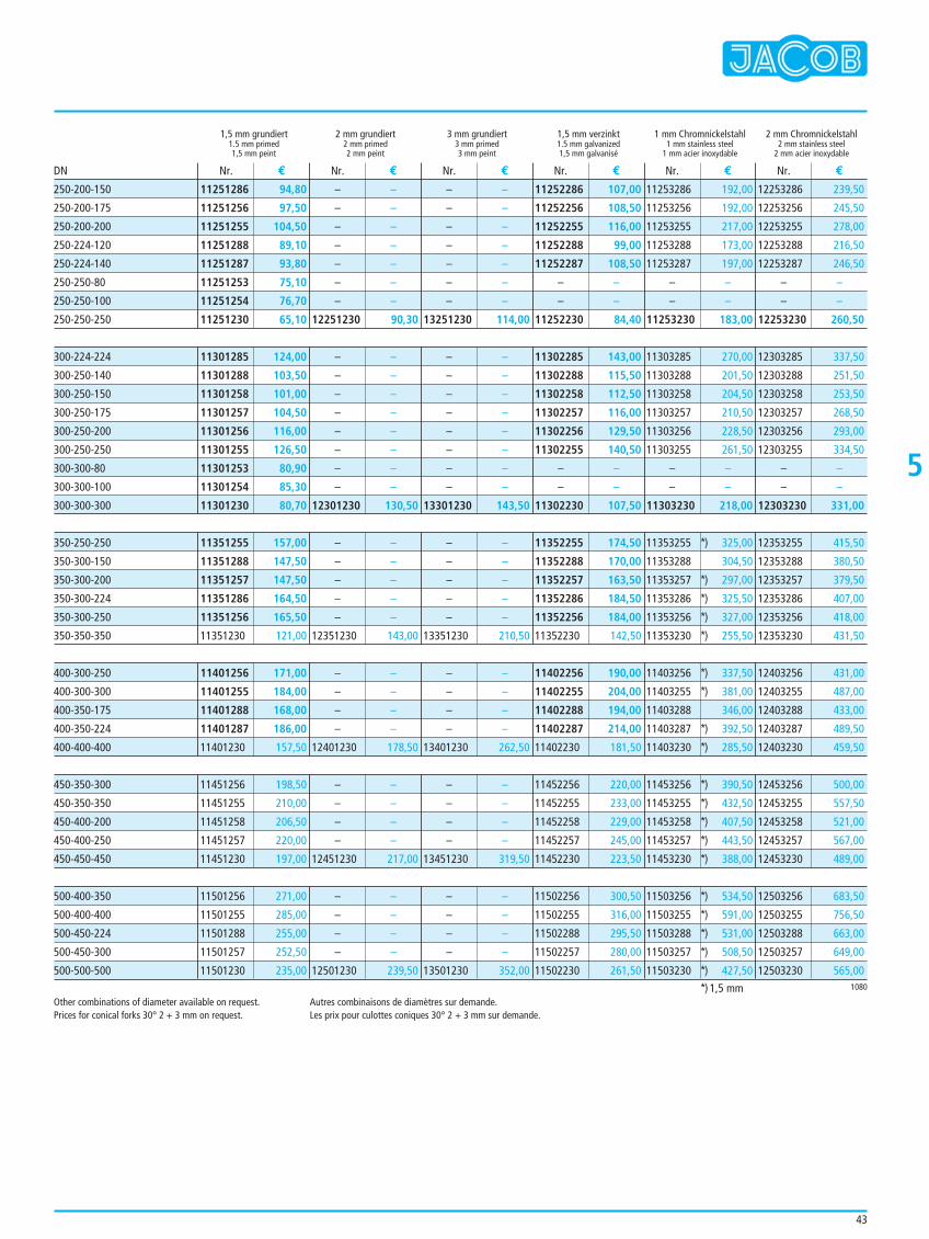
43
5
Other combinations of diameter available on request.Prices for conical forks 30° 2 + 3 mm on request.
Autres combinaisons de diamètres sur demande.Les prix pour culottes coniques 30° 2 + 3 mm sur demande.
1,5 mm grundiert 2 mm grundiert 3 mm grundiert 1,5 mm verzinkt 1 mm Chromnickelstahl 2 mm Chromnickelstahl1.5 mm primed 2 mm primed 3 mm primed 1.5 mm galvanized 1 mm stainless steel 2 mm stainless steel1,5 mm peint 2 mm peint 3 mm peint 1,5 mm galvanisé 1 mm acier inoxydable 2 mm acier inoxydable
11251286 94,80
11251256 97,50
11251255 104,50
11251288 89,10
11251287 93,80
11251253 75,10
11251254 76,70
11251230 65,10
11301285 124,00
11301288 103,50
11301258 101,00
11301257 104,50
11301256 116,00
11301255 126,50
11301253 80,90
11301254 85,30
11301230 80,70
11351255 157,00
11351288 147,50
11351257 147,50
11351286 164,50
11351256 165,50
11351230 121,00
11401256 171,00
11401255 184,00
11401288 168,00
11401287 186,00
11401230 157,50
11451256 198,50
11451255 210,00
11451258 206,50
11451257 220,00
11451230 197,00
11501256 271,00
11501255 285,00
11501288 255,00
11501257 252,50
11501230 235,00
– –
– –
– –
– –
– –
– –
– –
12251230 90,30
– –
– –
– –
– –
– –
– –
– –
– –
12301230 130,50
– –
– –
– –
– –
– –
12351230 143,00
– –
– –
– –
– –
12401230 178,50
– –
– –
– –
– –
12451230 217,00
– –
– –
– –
– –
12501230 239,50
– –
– –
– –
– –
– –
– –
– –
13251230 114,00
– –
– –
– –
– –
– –
– –
– –
– –
13301230 143,50
– –
– –
– –
– –
– –
13351230 210,50
– –
– –
– –
– –
13401230 262,50
– –
– –
– –
– –
13451230 319,50
– –
– –
– –
– –
13501230 352,00
11252286 107,00
11252256 108,50
11252255 116,00
11252288 99,00
11252287 108,50
– –
– –
11252230 84,40
11302285 143,00
11302288 115,50
11302258 112,50
11302257 116,00
11302256 129,50
11302255 140,50
– –
– –
11302230 107,50
11352255 174,50
11352288 170,00
11352257 163,50
11352286 184,50
11352256 184,00
11352230 142,50
11402256 190,00
11402255 204,00
11402288 194,00
11402287 214,00
11402230 181,50
11452256 220,00
11452255 233,00
11452258 229,00
11452257 245,00
11452230 223,50
11502256 300,50
11502255 316,00
11502288 295,50
11502257 280,00
11502230 261,50
11253286 192,00
11253256 192,00
11253255 217,00
11253288 173,00
11253287 197,00
– –
– –
11253230 183,00
11303285 270,00
11303288 201,50
11303258 204,50
11303257 210,50
11303256 228,50
11303255 261,50
– –
– –
11303230 218,00
11353255 *) 325,00
11353288 304,50
11353257 *) 297,00
11353286 *) 325,50
11353256 *) 327,00
11353230 *) 255,50
11403256 *) 337,50
11403255 *) 381,00
11403288 346,00
11403287 *) 392,50
11403230 *) 285,50
11453256 *) 390,50
11453255 *) 432,50
11453258 *) 407,50
11453257 *) 443,50
11453230 *) 388,00
11503256 *) 534,50
11503255 *) 591,00
11503288 *) 531,00
11503257 *) 508,50
11503230 *) 427,50
12253286 239,50
12253256 245,50
12253255 278,00
12253288 216,50
12253287 246,50
– –
– –
12253230 260,50
12303285 337,50
12303288 251,50
12303258 253,50
12303257 268,50
12303256 293,00
12303255 334,50
– –
– –
12303230 331,00
12353255 415,50
12353288 380,50
12353257 379,50
12353286 407,00
12353256 418,00
12353230 431,50
12403256 431,00
12403255 487,00
12403288 433,00
12403287 489,50
12403230 459,50
12453256 500,00
12453255 557,50
12453258 521,00
12453257 567,00
12453230 489,00
12503256 683,50
12503255 756,50
12503288 663,00
12503257 649,00
12503230 565,00
Nr. € Nr. € Nr. € Nr. € Nr. € Nr. €DN
1080
250-200-150
250-200-175
250-200-200
250-224-120
250-224-140
250-250-80
250-250-100
250-250-250
300-224-224
300-250-140
300-250-150
300-250-175
300-250-200
300-250-250
300-300-80
300-300-100
300-300-300
350-250-250
350-300-150
350-300-200
350-300-224
350-300-250
350-350-350
400-300-250
400-300-300
400-350-175
400-350-224
400-400-400
450-350-300
450-350-350
450-400-200
450-400-250
450-450-450
500-400-350
500-400-400
500-450-224
500-450-300
500-500-500
*) 1,5 mm
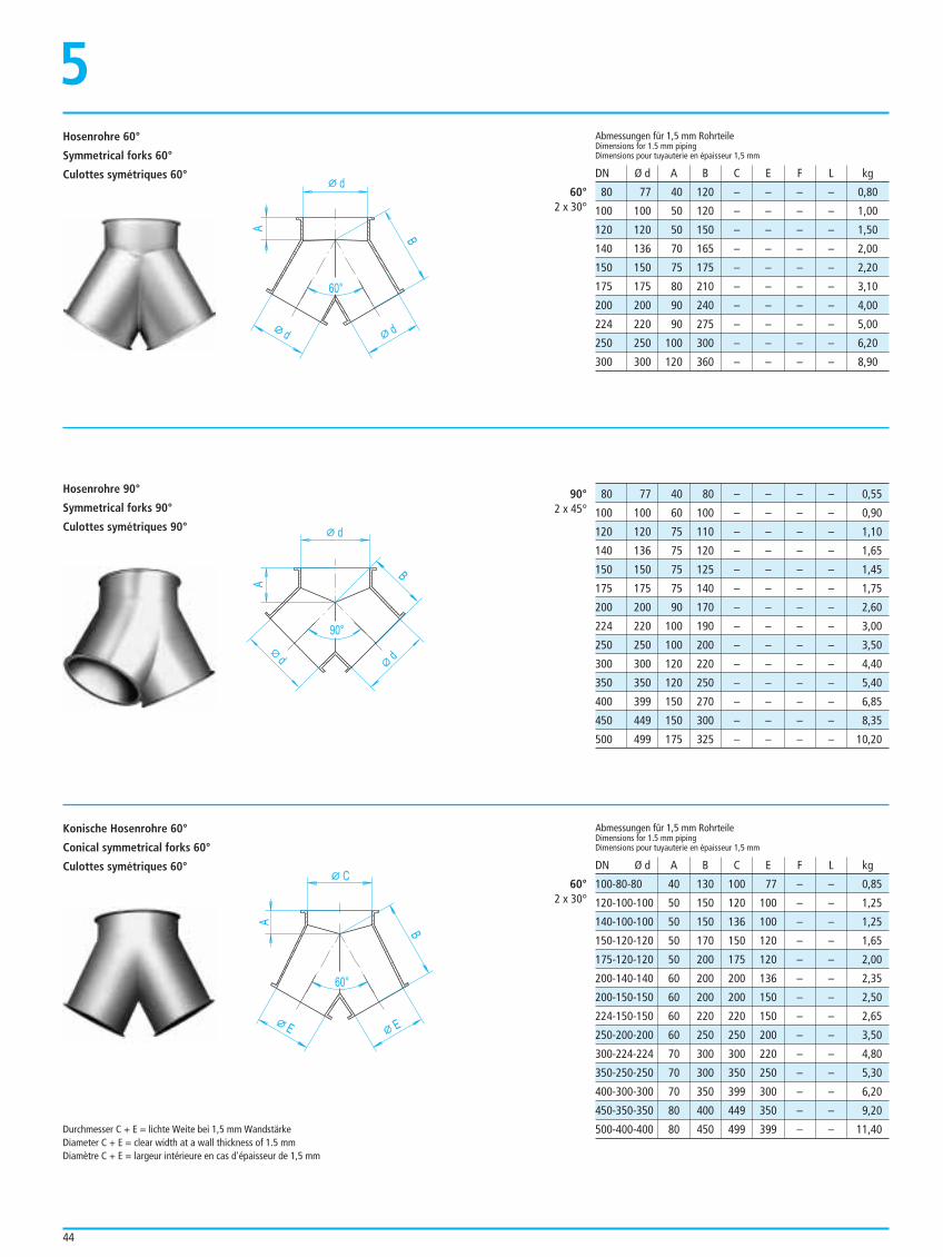
44
d
d
B
90°
A
d
C
60°
A
E
B
E
Durchmesser C + E = lichte Weite bei 1,5 mm WandstärkeDiameter C + E = clear width at a wall thickness of 1.5 mmDiamètre C + E = largeur intérieure en cas d'épaisseur de 1,5 mm
80 77 40 120 – – – – 0,80
100 100 50 120 – – – – 1,00
120 120 50 150 – – – – 1,50
140 136 70 165 – – – – 2,00
150 150 75 175 – – – – 2,20
175 175 80 210 – – – – 3,10
200 200 90 240 – – – – 4,00
224 220 90 275 – – – – 5,00
250 250 100 300 – – – – 6,20
300 300 120 360 – – – – 8,90
Abmessungen für 1,5 mm RohrteileDimensions for 1.5 mm pipingDimensions pour tuyauterie en épaisseur 1,5 mm
Abmessungen für 1,5 mm RohrteileDimensions for 1.5 mm pipingDimensions pour tuyauterie en épaisseur 1,5 mm
DN Ø d A B C E F L kg
DN Ø d A B C E F L kg
60°2 x 30°
90°2 x 45°
Hosenrohre 60°
Symmetrical forks 60°
Culottes symétriques 60°
5
Hosenrohre 90°
Symmetrical forks 90°
Culottes symétriques 90°
Konische Hosenrohre 60°
Conical symmetrical forks 60°
Culottes symétriques 60°
80 77 40 80 – – – – 0,55
100 100 60 100 – – – – 0,90
120 120 75 110 – – – – 1,10
140 136 75 120 – – – – 1,65
150 150 75 125 – – – – 1,45
175 175 75 140 – – – – 1,75
200 200 90 170 – – – – 2,60
224 220 100 190 – – – – 3,00
250 250 100 200 – – – – 3,50
300 300 120 220 – – – – 4,40
350 350 120 250 – – – – 5,40
400 399 150 270 – – – – 6,85
450 449 150 300 – – – – 8,35
500 499 175 325 – – – – 10,20
60°2 x 30°
100-80-80 40 130 100 77 – – 0,85
120-100-100 50 150 120 100 – – 1,25
140-100-100 50 150 136 100 – – 1,25
150-120-120 50 170 150 120 – – 1,65
175-120-120 50 200 175 120 – – 2,00
200-140-140 60 200 200 136 – – 2,35
200-150-150 60 200 200 150 – – 2,50
224-150-150 60 220 220 150 – – 2,65
250-200-200 60 250 250 200 – – 3,50
300-224-224 70 300 300 220 – – 4,80
350-250-250 70 300 350 250 – – 5,30
400-300-300 70 350 399 300 – – 6,20
450-350-350 80 400 449 350 – – 9,20
500-400-400 80 450 499 399 – – 11,40
d
d
B
60°
A
d
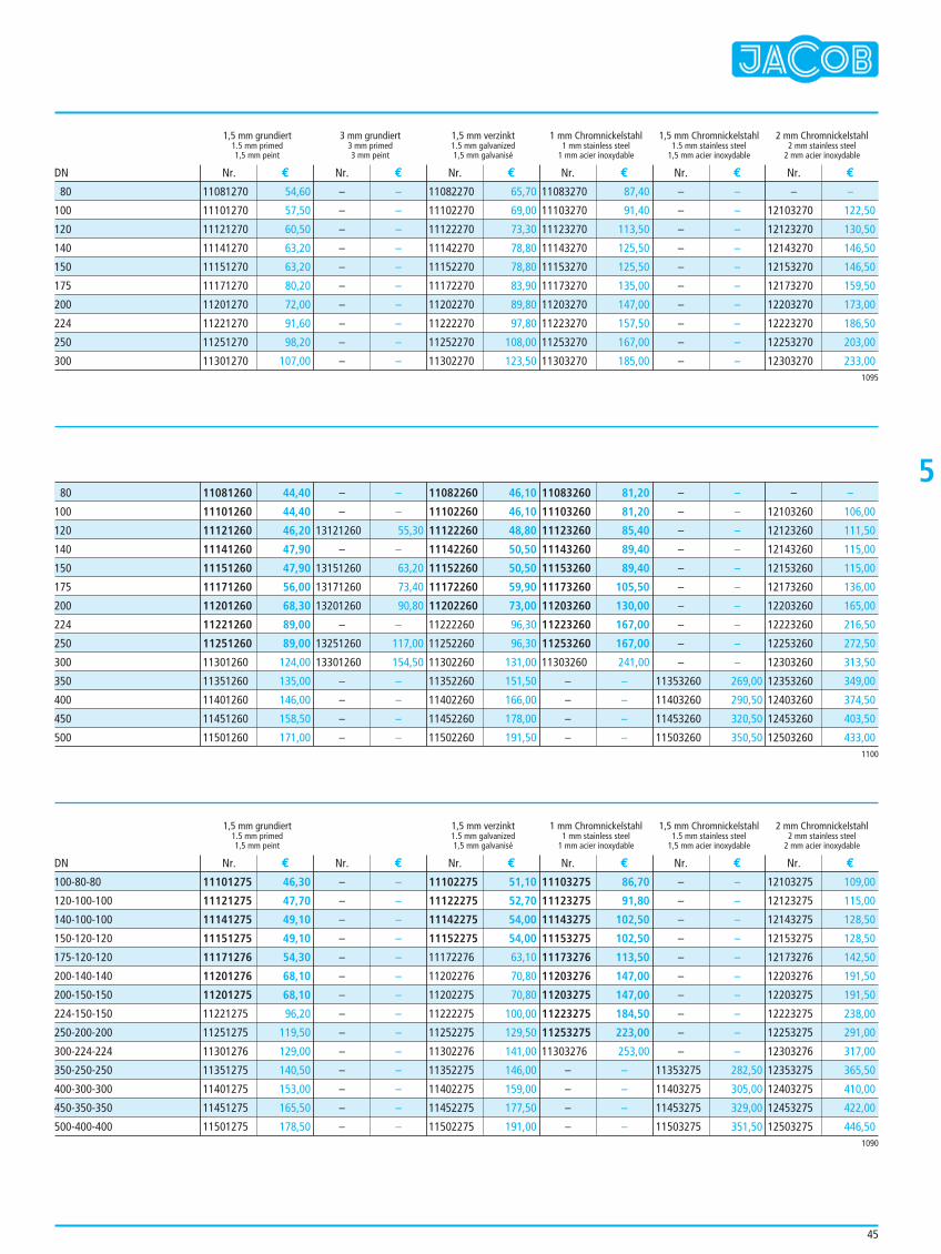
45
5
1,5 mm grundiert 3 mm grundiert 1,5 mm verzinkt 1 mm Chromnickelstahl 1,5 mm Chromnickelstahl 2 mm Chromnickelstahl1.5 mm primed 3 mm primed 1.5 mm galvanized 1 mm stainless steel 1.5 mm stainless steel 2 mm stainless steel1,5 mm peint 3 mm peint 1,5 mm galvanisé 1 mm acier inoxydable 1,5 mm acier inoxydable 2 mm acier inoxydable
1,5 mm grundiert 1,5 mm verzinkt 1 mm Chromnickelstahl 1,5 mm Chromnickelstahl 2 mm Chromnickelstahl1.5 mm primed 1.5 mm galvanized 1 mm stainless steel 1.5 mm stainless steel 2 mm stainless steel1,5 mm peint 1,5 mm galvanisé 1 mm acier inoxydable 1,5 mm acier inoxydable 2 mm acier inoxydable
11081270 54,60
11101270 57,50
11121270 60,50
11141270 63,20
11151270 63,20
11171270 80,20
11201270 72,00
11221270 91,60
11251270 98,20
11301270 107,00
– –
– –
– –
– –
– –
– –
– –
– –
– –
– –
11082270 65,70
11102270 69,00
11122270 73,30
11142270 78,80
11152270 78,80
11172270 83,90
11202270 89,80
11222270 97,80
11252270 108,00
11302270 123,50
11083270 87,40
11103270 91,40
11123270 113,50
11143270 125,50
11153270 125,50
11173270 135,00
11203270 147,00
11223270 157,50
11253270 167,00
11303270 185,00
– –
– –
– –
– –
– –
– –
– –
– –
– –
– –
– –
12103270 122,50
12123270 130,50
12143270 146,50
12153270 146,50
12173270 159,50
12203270 173,00
12223270 186,50
12253270 203,00
12303270 233,00
Nr. € Nr. € Nr. € Nr. € Nr. € Nr. €
Nr. € Nr. € Nr. € Nr. € Nr. € Nr. €
DN
DN
1095
80
100
120
140
150
175
200
224
250
300
1100
11081260 44,40
11101260 44,40
11121260 46,20
11141260 47,90
11151260 47,90
11171260 56,00
11201260 68,30
11221260 89,00
11251260 89,00
11301260 124,00
11351260 135,00
11401260 146,00
11451260 158,50
11501260 171,00
– –
– –
13121260 55,30
– –
13151260 63,20
13171260 73,40
13201260 90,80
– –
13251260 117,00
13301260 154,50
– –
– –
– –
– –
11082260 46,10
11102260 46,10
11122260 48,80
11142260 50,50
11152260 50,50
11172260 59,90
11202260 73,00
11222260 96,30
11252260 96,30
11302260 131,00
11352260 151,50
11402260 166,00
11452260 178,00
11502260 191,50
11083260 81,20
11103260 81,20
11123260 85,40
11143260 89,40
11153260 89,40
11173260 105,50
11203260 130,00
11223260 167,00
11253260 167,00
11303260 241,00
– –
– –
– –
– –
– –
– –
– –
– –
– –
– –
– –
– –
– –
– –
11353260 269,00
11403260 290,50
11453260 320,50
11503260 350,50
– –
12103260 106,00
12123260 111,50
12143260 115,00
12153260 115,00
12173260 136,00
12203260 165,00
12223260 216,50
12253260 272,50
12303260 313,50
12353260 349,00
12403260 374,50
12453260 403,50
12503260 433,00
80
100
120
140
150
175
200
224
250
300
350
400
450
500
1090
11101275 46,30
11121275 47,70
11141275 49,10
11151275 49,10
11171276 54,30
11201276 68,10
11201275 68,10
11221275 96,20
11251275 119,50
11301276 129,00
11351275 140,50
11401275 153,00
11451275 165,50
11501275 178,50
– –
– –
– –
– –
– –
– –
– –
– –
– –
– –
– –
– –
– –
– –
11102275 51,10
11122275 52,70
11142275 54,00
11152275 54,00
11172276 63,10
11202276 70,80
11202275 70,80
11222275 100,00
11252275 129,50
11302276 141,00
11352275 146,00
11402275 159,00
11452275 177,50
11502275 191,00
11103275 86,70
11123275 91,80
11143275 102,50
11153275 102,50
11173276 113,50
11203276 147,00
11203275 147,00
11223275 184,50
11253275 223,00
11303276 253,00
– –
– –
– –
– –
– –
– –
– –
– –
– –
– –
– –
– –
– –
– –
11353275 282,50
11403275 305,00
11453275 329,00
11503275 351,50
12103275 109,00
12123275 115,00
12143275 128,50
12153275 128,50
12173276 142,50
12203276 191,50
12203275 191,50
12223275 238,00
12253275 291,00
12303276 317,00
12353275 365,50
12403275 410,00
12453275 422,00
12503275 446,50
100-80-80
120-100-100
140-100-100
150-120-120
175-120-120
200-140-140
200-150-150
224-150-150
250-200-200
300-224-224
350-250-250
400-300-300
450-350-350
500-400-400
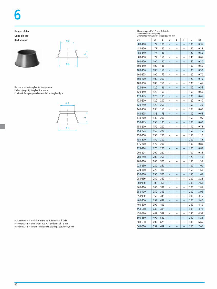
46
Durchmesser A + B = lichte Weite bei 1,5 mm WandstärkeDiameter A + B = clear width at a wall thickness of 1.5 mmDiamètre A + B = largeur intérieure en cas d'épaisseur de 1,5 mm
80-100 77 100 – – – 100 0,35
80-120 77 120 – – – 80 0,35
80-140 77 136 – – – 120 0,55
80-150 77 150 – – – 140 0,65
100-120 100 120 – – – 60 0,30
100-140 100 136 – – – 100 0,50
100-150 100 150 – – – 95 0,50
100-175 100 175 – – – 120 0,70
100-200 100 200 – – – 120 0,75
100-250 100 250 – – – 200 1,45
120-140 120 136 – – – 100 0,55
120-150 120 150 – – – 150 0,60
120-175 120 175 – – – 100 0,65
120-200 120 200 – – – 120 0,80
120-250 120 250 – – – 150 1,20
140-150 136 150 – – – 100 0,60
140-175 136 175 – – – 100 0,65
140-200 136 200 – – – 150 1,05
150-175 150 175 – – – 100 0,60
150-200 150 200 – – – 100 0,75
150-224 150 220 – – – 150 1,15
150-250 150 250 – – – 150 1,10
150-300 150 300 – – – 200 1,85
175-200 175 200 – – – 100 0,80
175-224 175 220 – – – 100 0,85
200-224 200 220 – – – 100 0,85
200-250 200 250 – – – 120 1,10
200-300 200 300 – – – 150 1,55
224-250 220 250 – – – 100 1,00
224-300 220 300 – – – 150 1,60
250-300 250 300 – – – 150 1,65
250/350 250 350 – – – 200 2,28
300/350 300 350 – – – 200 2,60
300-400 300 399 – – – 200 2,85
350-400 350 399 – – – 200 2,95
350/450 350 449 – – – 200 3,15
400-450 399 449 – – – 200 3,40
400-500 399 499 – – – 250 4,40
450-500 449 499 – – – 200 3,70
450-560 449 559 – – – 250 4,99
500-560 499 559 – – – 250 5,23
500-630 499 629 – – – 300 6,65
560-630 559 629 – – – 300 7,00
Abmessungen für 1,5 mm RohrteileDimensions for 1.5 mm pipingDimensions pour tuyauterie en épaisseur 1,5 mm
DN A B C E F L kgA
L
B
A
L
B
Konusstücke
Cone pieces
Réductions
6
Rohrende teilweise zylindrisch ausgeformt.End of pipe partly in cylindrical shape.Extrémité de tuyau partiellement de forme cylindrique.
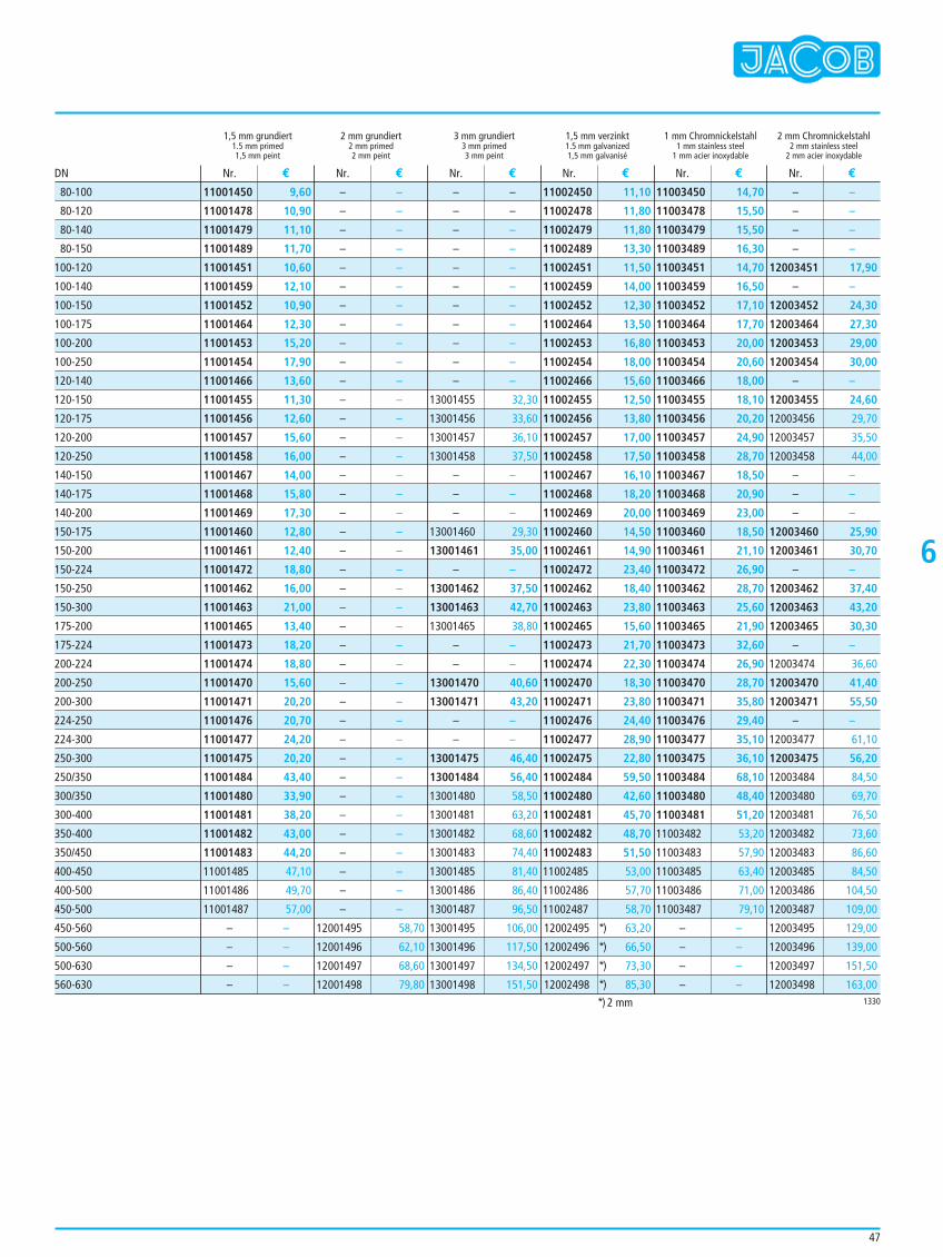
47
1,5 mm grundiert 2 mm grundiert 3 mm grundiert 1,5 mm verzinkt 1 mm Chromnickelstahl 2 mm Chromnickelstahl1.5 mm primed 2 mm primed 3 mm primed 1.5 mm galvanized 1 mm stainless steel 2 mm stainless steel1,5 mm peint 2 mm peint 3 mm peint 1,5 mm galvanisé 1 mm acier inoxydable 2 mm acier inoxydable
11001450 9,60
11001478 10,90
11001479 11,10
11001489 11,70
11001451 10,60
11001459 12,10
11001452 10,90
11001464 12,30
11001453 15,20
11001454 17,90
11001466 13,60
11001455 11,30
11001456 12,60
11001457 15,60
11001458 16,00
11001467 14,00
11001468 15,80
11001469 17,30
11001460 12,80
11001461 12,40
11001472 18,80
11001462 16,00
11001463 21,00
11001465 13,40
11001473 18,20
11001474 18,80
11001470 15,60
11001471 20,20
11001476 20,70
11001477 24,20
11001475 20,20
11001484 43,40
11001480 33,90
11001481 38,20
11001482 43,00
11001483 44,20
11001485 47,10
11001486 49,70
11001487 57,00
– –
– –
– –
– –
– –
– –
– –
– –
– –
– –
– –
– –
– –
– –
– –
– –
– –
– –
– –
– –
– –
– –
– –
– –
– –
– –
– –
– –
– –
– –
– –
– –
– –
– –
– –
– –
– –
– –
– –
– –
– –
– –
– –
12001495 58,70
12001496 62,10
12001497 68,60
12001498 79,80
– –
– –
– –
– –
– –
– –
– –
– –
– –
– –
– –
13001455 32,30
13001456 33,60
13001457 36,10
13001458 37,50
– –
– –
– –
13001460 29,30
13001461 35,00
– –
13001462 37,50
13001463 42,70
13001465 38,80
– –
– –
13001470 40,60
13001471 43,20
– –
– –
13001475 46,40
13001484 56,40
13001480 58,50
13001481 63,20
13001482 68,60
13001483 74,40
13001485 81,40
13001486 86,40
13001487 96,50
13001495 106,00
13001496 117,50
13001497 134,50
13001498 151,50
11002450 11,10
11002478 11,80
11002479 11,80
11002489 13,30
11002451 11,50
11002459 14,00
11002452 12,30
11002464 13,50
11002453 16,80
11002454 18,00
11002466 15,60
11002455 12,50
11002456 13,80
11002457 17,00
11002458 17,50
11002467 16,10
11002468 18,20
11002469 20,00
11002460 14,50
11002461 14,90
11002472 23,40
11002462 18,40
11002463 23,80
11002465 15,60
11002473 21,70
11002474 22,30
11002470 18,30
11002471 23,80
11002476 24,40
11002477 28,90
11002475 22,80
11002484 59,50
11002480 42,60
11002481 45,70
11002482 48,70
11002483 51,50
11002485 53,00
11002486 57,70
11002487 58,70
12002495 *) 63,20
12002496 *) 66,50
12002497 *) 73,30
12002498 *) 85,30
11003450 14,70
11003478 15,50
11003479 15,50
11003489 16,30
11003451 14,70
11003459 16,50
11003452 17,10
11003464 17,70
11003453 20,00
11003454 20,60
11003466 18,00
11003455 18,10
11003456 20,20
11003457 24,90
11003458 28,70
11003467 18,50
11003468 20,90
11003469 23,00
11003460 18,50
11003461 21,10
11003472 26,90
11003462 28,70
11003463 25,60
11003465 21,90
11003473 32,60
11003474 26,90
11003470 28,70
11003471 35,80
11003476 29,40
11003477 35,10
11003475 36,10
11003484 68,10
11003480 48,40
11003481 51,20
11003482 53,20
11003483 57,90
11003485 63,40
11003486 71,00
11003487 79,10
– –
– –
– –
– –
– –
– –
– –
– –
12003451 17,90
– –
12003452 24,30
12003464 27,30
12003453 29,00
12003454 30,00
– –
12003455 24,60
12003456 29,70
12003457 35,50
12003458 44,00
– –
– –
– –
12003460 25,90
12003461 30,70
– –
12003462 37,40
12003463 43,20
12003465 30,30
– –
12003474 36,60
12003470 41,40
12003471 55,50
– –
12003477 61,10
12003475 56,20
12003484 84,50
12003480 69,70
12003481 76,50
12003482 73,60
12003483 86,60
12003485 84,50
12003486 104,50
12003487 109,00
12003495 129,00
12003496 139,00
12003497 151,50
12003498 163,00
Nr. € Nr. € Nr. € Nr. € Nr. € Nr. €DN
1330
80-100
80-120
80-140
80-150
100-120
100-140
100-150
100-175
100-200
100-250
120-140
120-150
120-175
120-200
120-250
140-150
140-175
140-200
150-175
150-200
150-224
150-250
150-300
175-200
175-224
200-224
200-250
200-300
224-250
224-300
250-300
250/350
300/350
300-400
350-400
350/450
400-450
400-500
450-500
450-560
500-560
500-630
560-630
*) 2 mm
6
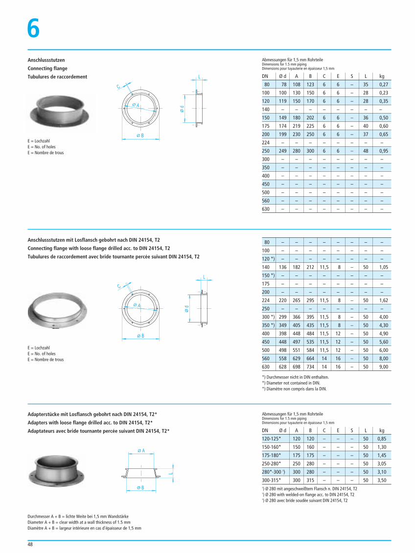
48
Anschlussstutzen
Connecting flange
Tubulures de raccordement
6
80 78 108 123 6 6 – 35 0,27
100 100 130 150 6 6 – 28 0,23
120 119 150 170 6 6 – 28 0,35
140 – – – – – – – –
150 149 180 202 6 6 – 36 0,50
175 174 219 225 6 6 – 40 0,60
200 199 230 250 6 6 – 37 0,65
224 – – – – – – – –
250 249 280 300 6 6 – 48 0,95
300 – – – – – – – –
350 – – – – – – – –
400 – – – – – – – –
450 – – – – – – – –
500 – – – – – – – –
560 – – – – – – – –
630 – – – – – – – –
Abmessungen für 1,5 mm RohrteileDimensions for 1.5 mm pipingDimensions pour tuyauterie en épaisseur 1,5 mm
Abmessungen für 1,5 mm RohrteileDimensions for 1.5 mm pipingDimensions pour tuyauterie en épaisseur 1,5 mm
DN Ø d A B C E S L kg
DN Ø d A B C E S L kg
B
C
dA
L
B
C
dA
L
80 – – – – – – – –
100 – – – – – – – –
120 *) – – – – – – – –
140 136 182 212 11,5 8 – 50 1,05
150 *) – – – – – – – –
175 – – – – – – – –
200 – – – – – – – –
224 220 265 295 11,5 8 – 50 1,62
250 – – – – – – – –
300 *) 299 366 395 11,5 8 – 50 4,00
350 *) 349 405 435 11,5 8 – 50 4,30
400 398 448 484 11,5 12 – 50 4,90
450 448 497 535 11,5 12 – 50 5,60
500 498 551 584 11,5 12 – 50 6,00
560 558 629 664 14 16 – 50 8,00
630 628 698 734 14 16 – 50 9,00
E = LochzahlE = No. of holesE = Nombre de trous
E = LochzahlE = No. of holesE = Nombre de trous
Anschlussstutzen mit Losflansch gebohrt nach DIN 24154, T2
Connecting flange with loose flange drilled acc. to DIN 24154, T2
Tubulures de raccordement avec bride tournante percée suivant DIN 24154, T2
A
B
L
120-125* 120 120 – – – 50 0,85
150-160* 150 160 – – – 50 1,30
175-180* 175 175 – – – 50 1,45
250-280* 250 280 – – – 50 3,05
280*-300 1) 300 280 – – – 50 3,10
300-315* 300 315 – – – 50 3,50
Adapterstücke mit Losflansch gebohrt nach DIN 24154, T2*
Adapters with loose flange drilled acc. to DIN 24154, T2*
Adaptateurs avec bride tournante percée suivant DIN 24154, T2*
Durchmesser A + B = lichte Weite bei 1,5 mm WandstärkeDiameter A + B = clear width at a wall thickness of 1.5 mmDiamètre A + B = largeur intérieure en cas d'épaisseur de 1,5 mm
1) Ø 280 mit angeschweißtem Flansch n. DIN 24154, T21) Ø 280 with welded-on flange acc. to DIN 24154, T21) Ø 280 avec bride soudée suivant DIN 24154, T2
*) Durchmesser nicht in DIN enthalten.*) Diameter not contained in DIN.*) Diamètre non compris dans la DIN.
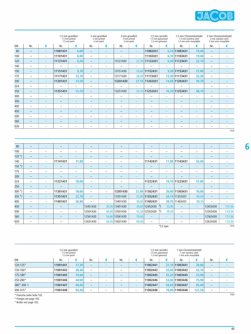
49
6
1,5 mm grundiert 2 mm grundiert 3 mm grundiert 1,5 mm verzinkt 1,5 mm Chromnickelstahl 2 mm Chromnickelstahl1.5 mm primed 2 mm primed 3 mm primed 1.5 mm galvanized 1.5 mm stainless steel 2 mm stainless steel1,5 mm peint 2 mm peint 3 mm peint 1,5 mm galvanisé 1,5 mm acier inoxydable 2 mm acier inoxydable
1,5 mm grundiert 1,5 mm verzinkt 1 mm Chromnickelstahl1.5 mm primed 1.5 mm galvanized 1 mm stainless steel1,5 mm peint 1,5 mm galvanisé 1 mm acier inoxydable
– –
– –
– –
– –
– –
– –
– –
– –
– –
– –
– –
– –
– –
– –
– –
– –
11081431 6,00
11101431 6,00
11121431 6,20
– –
11151431 9,20
11171431 12,70
11201431 13,50
– –
11251431 15,10
– –
– –
– –
– –
– –
– –
– –
– –
– –
– –
– –
– –
– –
– –
– –
– –
– –
– –
– –
– –
– –
– –
– –
– –
– –
13121430 22,70
– –
13151430 24,60
13171430 28,40
13201430 27,10
– –
13251430 33,10
– –
– –
– –
– –
– –
– –
– –
11082431 6,10
11102431 6,10
11122431 6,40
– –
11152431 9,30
11172431 13,30
11202431 14,60
– –
11252431 16,70
– –
– –
– –
– –
– –
– –
– –
11083431 19,40
11103431 19,40
11123431 22,10
– –
11153431 27,00
11173431 33,30
11203431 39,70
– –
11253431 48,10
– –
– –
– –
– –
– –
– –
– –
– –
– –
– –
– –
– –
– –
– –
– –
– –
– –
– –
– –
– –
– –
– –
– –
Nr. € Nr. € Nr. € Nr. € Nr. € Nr. € Nr. €
Nr. € Nr. € Nr. € Nr. € Nr. € Nr. €
DN
DN
1310
80
100
120
140
150
175
200
224
250
300
350
400
450
500
560
630
*) 2 mm 1315
– –
– –
– –
– –
– –
– –
– –
– –
– –
– –
– –
– –
– –
– –
– –
– –
– –
– –
– –
11141431 11,80
– –
– –
– –
11221431 18,00
– –
11301431 18,60
11351431 22,70
11401431 26,90
– –
– –
– –
– –
– –
– –
– –
– –
– –
– –
– –
– –
– –
– –
– –
– –
12451430 30,90
12501430 36,90
12561430 54,80
12631430 59,40
– –
– –
– –
– –
– –
– –
– –
– –
– –
13301430 21,90
13351430 25,00
13401430 30,00
13451430 34,60
13501430 41,20
13561430 79,00
13631430 90,00
– –
– –
– –
11142431 11,90
– –
– –
– –
11222431 19,10
– –
11302431 20,00
11352431 24,10
11402431 28,70
12452430 *) 33,80
12502430 *) 39,30
– –
– –
– –
– –
– –
11143431 32,40
– –
– –
– –
11223431 57,80
– –
11303431 76,00
11353431 80,60
11403431 89,50
– –
– –
– –
– –
– –
– –
– –
– –
– –
– –
– –
– –
– –
– –
– –
– –
12453430 107,50
12503430 119,50
12563430 157,00
12633430 172,50
80
100
120 *)
140
150 *)
175
200
224
250
300 *)
350 *)
400
450
500
560
630
1320
11001441 17,30
11001443 28,40
11001445 19,60
11001446 44,60
11001447 48,60
11001448 64,40
– –
– –
– –
– –
– –
– –
– –
– –
– –
– –
– –
– –
11002441 22,10
11002443 33,40
11002445 25,20
11002446 53,60
11002447 58,60
11002448 79,60
11003441 29,60
11003443 55,10
11003445 33,90
11003446 75,90
11003447 85,40
11003448 121,50
– –
– –
– –
– –
– –
– –
120-125*
150-160*
175-180*
250-280*
280*-300 1)
300-315*
* Flansche siehe Seite 102.* Flanges see page 102.* Brides voir page 102.
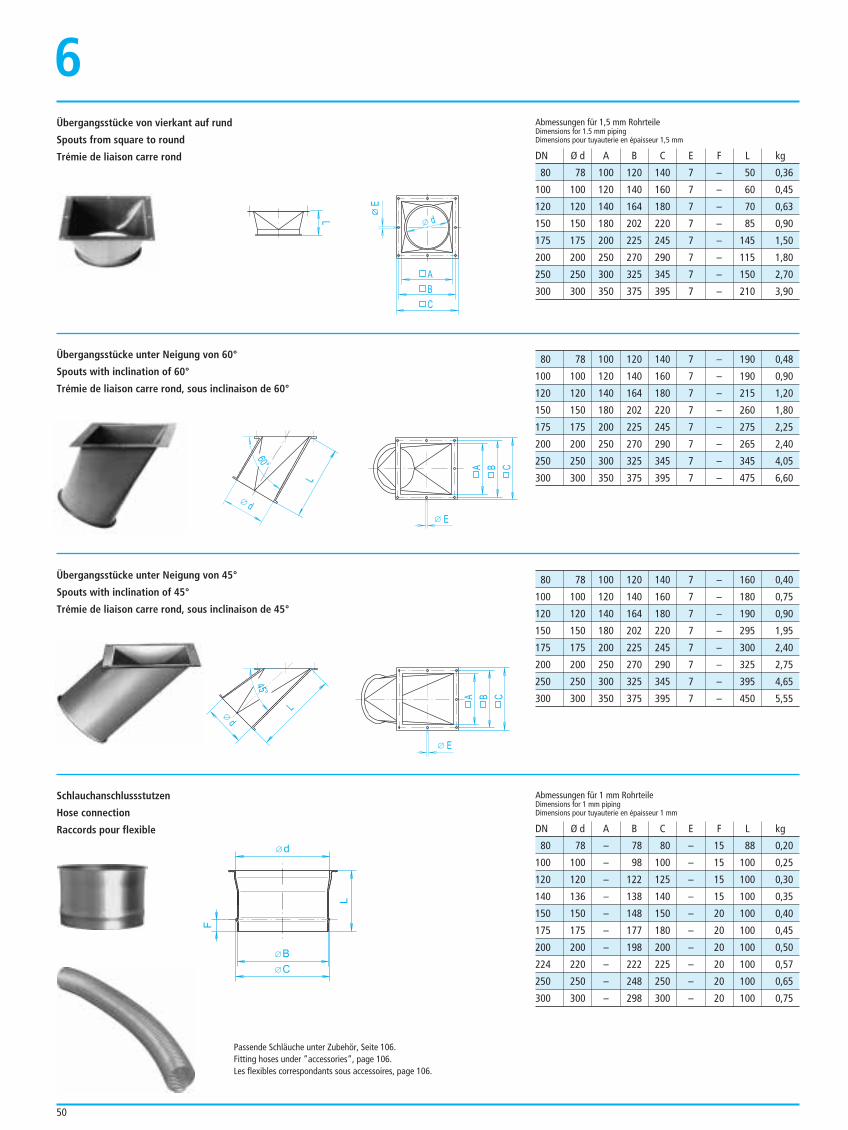
50
L
A
B
C
E
d
Passende Schläuche unter Zubehör, Seite 106.Fitting hoses under ”accessories”, page 106.Les flexibles correspondants sous accessoires, page 106.
Übergangsstücke von vierkant auf rund
Spouts from square to round
Trémie de liaison carre rond
6
A B C
E
d
L
60°
Übergangsstücke unter Neigung von 60°
Spouts with inclination of 60°
Trémie de liaison carre rond, sous inclinaison de 60°
Übergangsstücke unter Neigung von 45°
Spouts with inclination of 45°
Trémie de liaison carre rond, sous inclinaison de 45°
Schlauchanschlussstutzen
Hose connection
Raccords pour flexible
80 78 100 120 140 7 – 50 0,36
100 100 120 140 160 7 – 60 0,45
120 120 140 164 180 7 – 70 0,63
150 150 180 202 220 7 – 85 0,90
175 175 200 225 245 7 – 145 1,50
200 200 250 270 290 7 – 115 1,80
250 250 300 325 345 7 – 150 2,70
300 300 350 375 395 7 – 210 3,90
Abmessungen für 1,5 mm RohrteileDimensions for 1.5 mm pipingDimensions pour tuyauterie en épaisseur 1,5 mm
DN Ø d A B C E F L kg
80 78 – 78 80 – 15 88 0,20
100 100 – 98 100 – 15 100 0,25
120 120 – 122 125 – 15 100 0,30
140 136 – 138 140 – 15 100 0,35
150 150 – 148 150 – 20 100 0,40
175 175 – 177 180 – 20 100 0,45
200 200 – 198 200 – 20 100 0,50
224 220 – 222 225 – 20 100 0,57
250 250 – 248 250 – 20 100 0,65
300 300 – 298 300 – 20 100 0,75
Abmessungen für 1 mm RohrteileDimensions for 1 mm pipingDimensions pour tuyauterie en épaisseur 1 mm
DN Ø d A B C E F L kg
80 78 100 120 140 7 – 190 0,48
100 100 120 140 160 7 – 190 0,90
120 120 140 164 180 7 – 215 1,20
150 150 180 202 220 7 – 260 1,80
175 175 200 225 245 7 – 275 2,25
200 200 250 270 290 7 – 265 2,40
250 250 300 325 345 7 – 345 4,05
300 300 350 375 395 7 – 475 6,60
80 78 100 120 140 7 – 160 0,40
100 100 120 140 160 7 – 180 0,75
120 120 140 164 180 7 – 190 0,90
150 150 180 202 220 7 – 295 1,95
175 175 200 225 245 7 – 300 2,40
200 200 250 270 290 7 – 325 2,75
250 250 300 325 345 7 – 395 4,65
300 300 350 375 395 7 – 450 5,55A B C
E
d
L
45°
d
BC
L
F
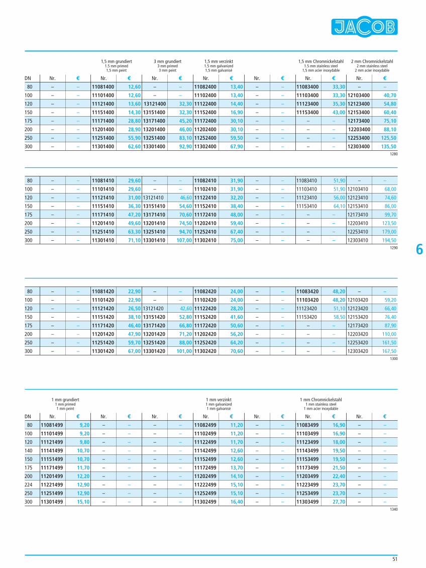
51
6
1,5 mm grundiert 3 mm grundiert 1,5 mm verzinkt 1,5 mm Chromnickelstahl 2 mm Chromnickelstahl1.5 mm primed 3 mm primed 1.5 mm galvanized 1.5 mm stainless steel 2 mm stainless steel1,5 mm peint 3 mm peint 1,5 mm galvanisé 1,5 mm acier inoxydable 2 mm acier inoxydable
1 mm grundiert 1 mm verzinkt 1 mm Chromnickelstahl1 mm primed 1 mm galvanized 1 mm stainless steel1 mm peint 1 mm galvanisé 1 mm acier inoxydable
– –
– –
– –
– –
– –
– –
– –
– –
11081400 12,60
11101400 12,60
11121400 13,60
11151400 14,30
11171400 28,80
11201400 28,90
11251400 55,90
11301400 62,60
– –
– –
13121400 32,30
13151400 32,30
13171400 45,20
13201400 46,00
13251400 83,10
13301400 92,90
11082400 13,40
11102400 13,40
11122400 14,40
11152400 16,90
11172400 30,10
11202400 30,10
11252400 59,50
11302400 67,90
– –
– –
– –
– –
– –
– –
– –
– –
11083400 33,30
11103400 33,30
11123400 35,30
11153400 43,00
– –
– –
– –
– –
– –
12103400 40,70
12123400 54,80
12153400 60,40
12173400 75,10
12203400 88,10
12253400 125,50
12303400 135,50
Nr. € Nr. € Nr. € Nr. € Nr. € Nr. € Nr. €
Nr. € Nr. € Nr. € Nr. € Nr. € Nr. € Nr. €
DN
DN
1280
80
100
120
150
175
200
250
300
1290
1300
– –
– –
– –
– –
– –
– –
– –
– –
11081410 29,60
11101410 29,60
11121410 31,00
11151410 36,30
11171410 47,20
11201410 49,60
11251410 63,30
11301410 71,10
– –
– –
13121410 46,60
13151410 54,60
13171410 70,60
13201410 74,50
13251410 94,70
13301410 107,00
11082410 31,90
11102410 31,90
11122410 32,20
11152410 38,40
11172410 48,00
11202410 59,40
11252410 67,40
11302410 75,00
– –
– –
– –
– –
– –
– –
– –
– –
11083410 51,90
11103410 51,90
11123410 56,00
11153410 64,10
– –
– –
– –
– –
– –
12103410 68,00
12123410 74,60
12153410 86,00
12173410 99,70
12203410 123,50
12253410 179,00
12303410 194,50
80
100
120
150
175
200
250
300
– –
– –
– –
– –
– –
– –
– –
– –
11081420 22,90
11101420 22,90
11121420 26,50
11151420 38,10
11171420 46,40
11201420 47,90
11251420 59,70
11301420 67,00
– –
– –
13121420 42,60
13151420 52,80
13171420 66,80
13201420 71,20
13251420 88,00
13301420 101,00
11082420 24,00
11102420 24,00
11122420 28,20
11152420 41,60
11172420 50,60
11202420 56,20
11252420 64,20
11302420 70,60
– –
– –
– –
– –
– –
– –
– –
– –
11083420 48,20
11103420 48,20
11123420 51,10
11153420 58,50
– –
– –
– –
– –
– –
12103420 59,20
12123420 66,40
12153420 76,40
12173420 87,90
12203420 110,00
12253420 161,50
12303420 167,50
80
100
120
150
175
200
250
300
1340
11081499 9,20
11101499 9,20
11121499 9,80
11141499 10,70
11151499 10,70
11171499 11,70
11201499 12,20
11221499 12,90
11251499 12,90
11301499 15,10
– –
– –
– –
– –
– –
– –
– –
– –
– –
– –
– –
– –
– –
– –
– –
– –
– –
– –
– –
– –
11082499 11,20
11102499 11,20
11122499 11,70
11142499 12,60
11152499 12,60
11172499 13,70
11202499 14,10
11222499 15,10
11252499 15,10
11302499 16,40
– –
– –
– –
– –
– –
– –
– –
– –
– –
– –
11083499 16,90
11103499 16,90
11123499 18,00
11143499 19,50
11153499 19,50
11173499 21,50
11203499 22,40
11223499 23,70
11253499 23,70
11303499 27,70
– –
– –
– –
– –
– –
– –
– –
– –
– –
– –
80
100
120
140
150
175
200
224
250
300
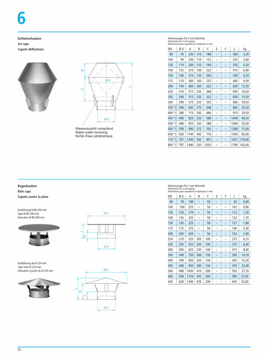
52
Deflektorhauben
Jet caps
Capots déflecteurs
6
d
AC
L
B
Wasseraustritt umlaufend
Water outlet revolving
Sortie d'eau périphérique
Regenhauben
Rain caps
Capots contre la pluie
d
A
C
L
d
A
B
L
C
80 76 230 110 188 – – 360 3,20
100 99 230 110 152 – – 325 3,40
120 119 260 125 169 – – 355 5,20
140 135 310 130 222 – – 415 6,40
150 149 310 130 200 – – 390 6,20
175 174 360 160 237 – – 460 9,50
200 199 460 200 322 – – 620 12,50
224 219 515 235 368 – – 695 16,50
250 249 515 235 322 – – 650 15,50
300 299 575 255 335 – – 680 18,50
350 *) 349 645 275 448 – – 865 25,50
400 *) 398 715 295 480 – – 915 29,50
450 *) 448 820 320 588 – – 1040 49,50
500 *) 498 870 320 588 – – 1040 53,50
560 *) 558 990 372 703 – – 1208 71,00
630 *) 628 1140 442 776 – – 1434 95,00
710 *) 707 1290 502 901 – – 1627 118,00
800 *) 797 1440 520 1020 – – 1790 142,00
Abmessungen für 2 mm RohrteileDimensions for 2 mm pipingDimensions pour tuyauterie en épaisseur 2 mm
Abmessungen für 2 mm RohrteileDimensions for 2 mm pipingDimensions pour tuyauterie en épaisseur 2 mm
DN Ø d A B C E F L kg
DN Ø d A B C E F L kg
Ausführung Ø 80-200 mmType Ø 80-200 mmExécution Ø 80-200 mm
Ausführung ab Ø 224 mmType from Ø 224 mmExécution à partir du Ø 224 mm
80 78 180 – 50 – – 92 0,60
100 100 225 – 50 – – 102 0,90
120 120 270 – 50 – – 112 1,30
140 136 325 – 50 – – 122 1,70
150 150 325 – 50 – – 127 1,80
175 175 375 – 50 – – 140 2,30
200 200 425 – 50 – – 152 2,90
224 219 525 205 100 – – 275 6,10
250 250 525 205 100 – – 275 6,40
300 300 625 230 100 – – 315 8,40
350 349 750 300 150 – – 395 14,70
400 398 850 320 150 – – 435 15,20
450 448 950 340 150 – – 470 22,00
500 498 1050 410 200 – – 550 27,70
560 558 1150 435 200 – – 590 27,00
630 628 1300 470 200 – – 645 32,00
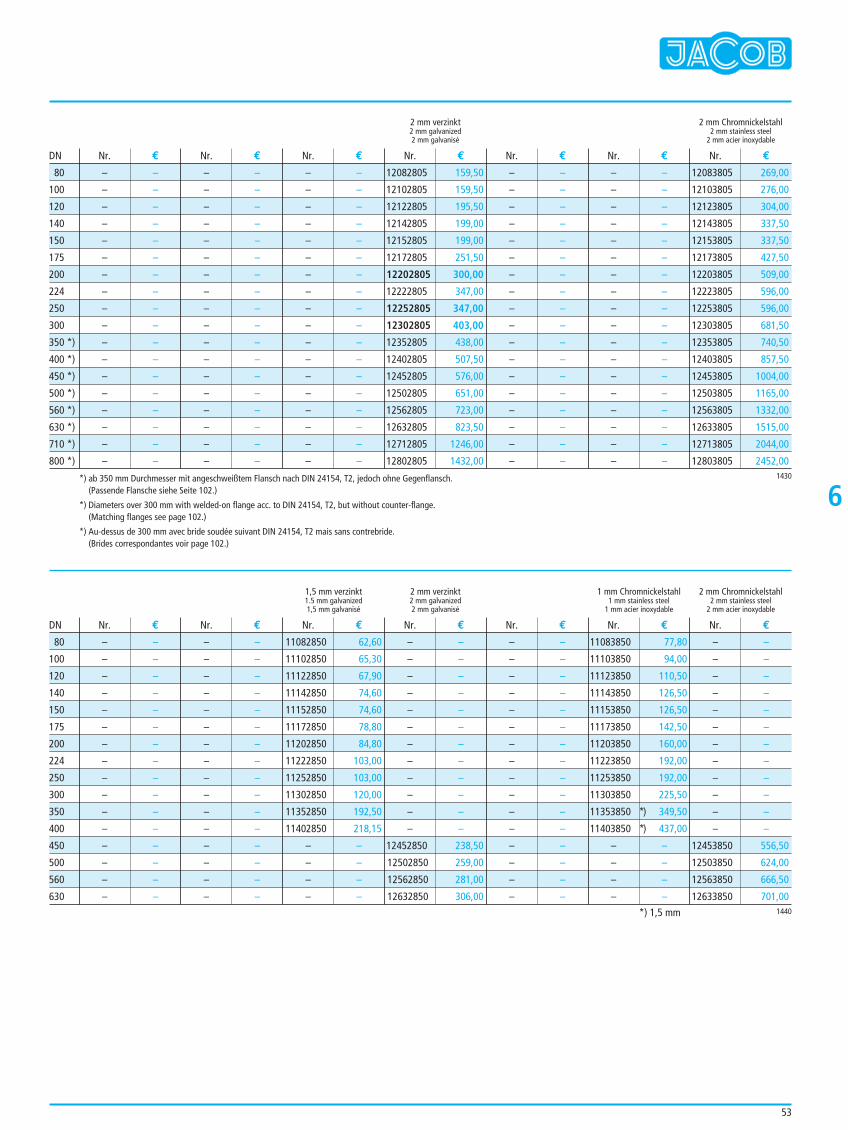
53
6
2 mm verzinkt 2 mm Chromnickelstahl2 mm galvanized 2 mm stainless steel2 mm galvanisé 2 mm acier inoxydable
1,5 mm verzinkt 2 mm verzinkt 1 mm Chromnickelstahl 2 mm Chromnickelstahl1.5 mm galvanized 2 mm galvanized 1 mm stainless steel 2 mm stainless steel1,5 mm galvanisé 2 mm galvanisé 1 mm acier inoxydable 2 mm acier inoxydable
– –
– –
– –
– –
– –
– –
– –
– –
– –
– –
– –
– –
– –
– –
– –
– –
– –
– –
– –
– –
– –
– –
– –
– –
– –
– –
– –
– –
– –
– –
– –
– –
– –
– –
– –
– –
– –
– –
– –
– –
– –
– –
– –
– –
– –
– –
– –
– –
– –
– –
– –
– –
– –
– –
12082805 159,50
12102805 159,50
12122805 195,50
12142805 199,00
12152805 199,00
12172805 251,50
12202805 300,00
12222805 347,00
12252805 347,00
12302805 403,00
12352805 438,00
12402805 507,50
12452805 576,00
12502805 651,00
12562805 723,00
12632805 823,50
12712805 1246,00
12802805 1432,00
– –
– –
– –
– –
– –
– –
– –
– –
– –
– –
– –
– –
– –
– –
– –
– –
– –
– –
– –
– –
– –
– –
– –
– –
– –
– –
– –
– –
– –
– –
– –
– –
– –
– –
– –
– –
12083805 269,00
12103805 276,00
12123805 304,00
12143805 337,50
12153805 337,50
12173805 427,50
12203805 509,00
12223805 596,00
12253805 596,00
12303805 681,50
12353805 740,50
12403805 857,50
12453805 1004,00
12503805 1165,00
12563805 1332,00
12633805 1515,00
12713805 2044,00
12803805 2452,00
Nr. € Nr. € Nr. € Nr. € Nr. € Nr. € Nr. €
Nr. € Nr. € Nr. € Nr. € Nr. € Nr. € Nr. €
DN
DN
1430
80
100
120
140
150
175
200
224
250
300
350 *)
400 *)
450 *)
500 *)
560 *)
630 *)
710 *)
800 *)
*) ab 350 mm Durchmesser mit angeschweißtem Flansch nach DIN 24154, T2, jedoch ohne Gegenflansch.(Passende Flansche siehe Seite 102.)
*) Diameters over 300 mm with welded-on flange acc. to DIN 24154, T2, but without counter-flange.(Matching flanges see page 102.)
*) Au-dessus de 300 mm avec bride soudée suivant DIN 24154, T2 mais sans contrebride.(Brides correspondantes voir page 102.)
1440
– –
– –
– –
– –
– –
– –
– –
– –
– –
– –
– –
– –
– –
– –
– –
– –
– –
– –
– –
– –
– –
– –
– –
– –
– –
– –
– –
– –
– –
– –
– –
– –
11082850 62,60
11102850 65,30
11122850 67,90
11142850 74,60
11152850 74,60
11172850 78,80
11202850 84,80
11222850 103,00
11252850 103,00
11302850 120,00
11352850 192,50
11402850 218,15
– –
– –
– –
– –
– –
– –
– –
– –
– –
– –
– –
– –
– –
– –
– –
– –
12452850 238,50
12502850 259,00
12562850 281,00
12632850 306,00
– –
– –
– –
– –
– –
– –
– –
– –
– –
– –
– –
– –
– –
– –
– –
– –
11083850 77,80
11103850 94,00
11123850 110,50
11143850 126,50
11153850 126,50
11173850 142,50
11203850 160,00
11223850 192,00
11253850 192,00
11303850 225,50
11353850 *) 349,50
11403850 *) 437,00
– –
– –
– –
– –
– –
– –
– –
– –
– –
– –
– –
– –
– –
– –
– –
– –
12453850 556,50
12503850 624,00
12563850 666,50
12633850 701,00
80
100
120
140
150
175
200
224
250
300
350
400
450
500
560
630
*) 1,5 mm
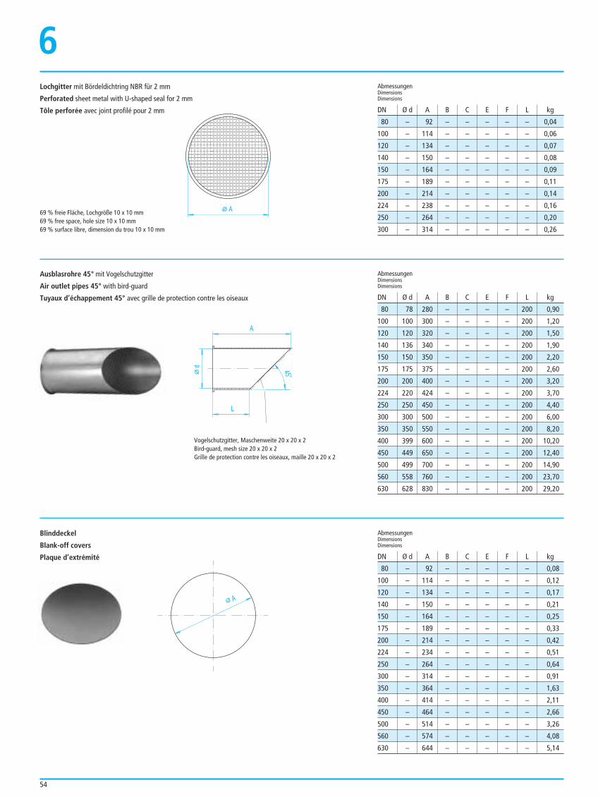
54
Lochgitter mit Bördeldichtring NBR für 2 mm
Perforated sheet metal with U-shaped seal for 2 mm
Tôle perforée avec joint profilé pour 2 mm
6
A69 % freie Fläche, Lochgröße 10 x 10 mm69 % free space, hole size 10 x 10 mm69 % surface libre, dimension du trou 10 x 10 mm
d
A
L
45°
80 – 92 – – – – – 0,04
100 – 114 – – – – – 0,06
120 – 134 – – – – – 0,07
140 – 150 – – – – – 0,08
150 – 164 – – – – – 0,09
175 – 189 – – – – – 0,11
200 – 214 – – – – – 0,14
224 – 238 – – – – – 0,16
250 – 264 – – – – – 0,20
300 – 314 – – – – – 0,26
AbmessungenDimensionsDimensions
AbmessungenDimensionsDimensions
AbmessungenDimensionsDimensions
DN Ø d A B C E F L kg
DN Ø d A B C E F L kg
DN Ø d A B C E F L kg
80 78 280 – – – – 200 0,90
100 100 300 – – – – 200 1,20
120 120 320 – – – – 200 1,50
140 136 340 – – – – 200 1,90
150 150 350 – – – – 200 2,20
175 175 375 – – – – 200 2,60
200 200 400 – – – – 200 3,20
224 220 424 – – – – 200 3,70
250 250 450 – – – – 200 4,40
300 300 500 – – – – 200 6,00
350 350 550 – – – – 200 8,20
400 399 600 – – – – 200 10,20
450 449 650 – – – – 200 12,40
500 499 700 – – – – 200 14,90
560 558 760 – – – – 200 23,70
630 628 830 – – – – 200 29,20
Ausblasrohre 45° mit Vogelschutzgitter
Air outlet pipes 45° with bird-guard
Tuyaux d’échappement 45° avec grille de protection contre les oiseaux
A
80 – 92 – – – – – 0,08
100 – 114 – – – – – 0,12
120 – 134 – – – – – 0,17
140 – 150 – – – – – 0,21
150 – 164 – – – – – 0,25
175 – 189 – – – – – 0,33
200 – 214 – – – – – 0,42
224 – 234 – – – – – 0,51
250 – 264 – – – – – 0,64
300 – 314 – – – – – 0,91
350 – 364 – – – – – 1,63
400 – 414 – – – – – 2,11
450 – 464 – – – – – 2,66
500 – 514 – – – – – 3,26
560 – 574 – – – – – 4,08
630 – 644 – – – – – 5,14
Blinddeckel
Blank-off covers
Plaque d’extrémité
Vogelschutzgitter, Maschenweite 20 x 20 x 2Bird-guard, mesh size 20 x 20 x 2Grille de protection contre les oiseaux, maille 20 x 20 x 2
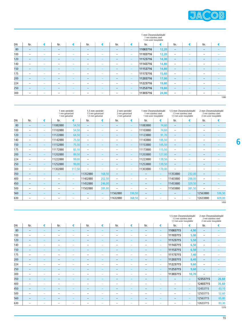
55
6
1 mm Chromnickelstahl1 mm stainless steel
1 mm acier inoxydable
1 mm verzinkt 1,5 mm verzinkt 2 mm verzinkt 1 mm Chromnickelstahl 1,5 mm Chromnickelstahl 2 mm Chromnickelstahl1 mm galvanized 1.5 mm galvanized 2 mm galvanized 1 mm stainless steel 1.5 mm stainless steel 2 mm stainless steel1 mm galvanisé 1,5 mm galvanisé 2 mm galvanisé 1 mm acier inoxydable 1,5 mm acier inoxydable 2 mm acier inoxydable
1,5 mm Chromnickelstahl 2 mm Chromnickelstahl1.5 mm stainless steel 2 mm stainless steel
1,5 mm acier inoxydable 2 mm acier inoxydable
– –
– –
– –
– –
– –
– –
– –
– –
– –
– –
– –
– –
– –
– –
– –
– –
– –
– –
– –
– –
– –
– –
– –
– –
– –
– –
– –
– –
– –
– –
– –
– –
– –
– –
– –
– –
– –
– –
– –
– –
11083716 12,20
11103716 12,20
11123716 14,30
11143716 14,80
11153716 14,80
11173716 15,60
11203716 17,00
11223716 19,80
11253716 19,80
11303716 24,00
– –
– –
– –
– –
– –
– –
– –
– –
– –
– –
– –
– –
– –
– –
– –
– –
– –
– –
– –
– –
Nr. € Nr. € Nr. € Nr. € Nr. € Nr. € Nr. €
Nr. € Nr. € Nr. € Nr. € Nr. € Nr. € Nr. €
Nr. € Nr. € Nr. € Nr. € Nr. € Nr. € Nr. €
DN
DN
DN
1380
80
100
120
140
150
175
200
224
250
300
1450
– –
– –
– –
– –
– –
– –
– –
– –
– –
– –
– –
– –
– –
– –
– –
– –
11082880 54,50
11102880 54,50
11122880 64,50
11142880 75,50
11152880 75,50
11172880 83,10
11202880 89,50
11222880 99,00
11252880 99,00
11302880 117,50
– –
– –
– –
– –
– –
– –
– –
– –
– –
– –
– –
– –
– –
– –
– –
– –
11352880 168,50
11402880 202,50
11452880 246,00
11502880 281,00
– –
– –
– –
– –
– –
– –
– –
– –
– –
– –
– –
– –
– –
– –
– –
– –
11562880 330,50
11632880 368,50
11083880 74,60
11103880 74,60
11123880 91,70
11143880 105,50
11153880 105,50
11173880 115,50
11203880 127,00
11223880 139,50
11253880 139,50
11303880 170,00
– –
– –
– –
– –
– –
– –
– –
– –
– –
– –
– –
– –
– –
– –
– –
– –
11353880 232,00
11403880 288,00
11453880 329,50
11503880 381,50
– –
– –
– –
– –
– –
– –
– –
– –
– –
– –
– –
– –
– –
– –
– –
– –
12563880 536,50
12633880 609,00
80
100
120
140
150
175
200
224
250
300
350
400
450
500
560
630
1370
– –
– –
– –
– –
– –
– –
– –
– –
– –
– –
– –
– –
– –
– –
– –
– –
– –
– –
– –
– –
– –
– –
– –
– –
– –
– –
– –
– –
– –
– –
– –
– –
– –
– –
– –
– –
– –
– –
– –
– –
– –
– –
– –
– –
– –
– –
– –
– –
– –
– –
– –
– –
– –
– –
– –
– –
– –
– –
– –
– –
– –
– –
– –
– –
– –
– –
– –
– –
– –
– –
– –
– –
– –
– –
– –
– –
– –
– –
– –
– –
11083715 4,90
11103715 5,00
11123715 5,50
11143715 6,50
11153715 6,50
11173715 7,40
11203715 8,40
11223715 9,60
11253715 9,60
11303715 10,70
– –
– –
– –
– –
– –
– –
– –
– –
– –
– –
– –
– –
– –
– –
– –
– –
12353715 26,60
12403715 35,60
12453715 43,10
12503715 52,60
12563715 65,80
12633715 83,30
80
100
120
140
150
175
200
224
250
300
350
400
450
500
560
630
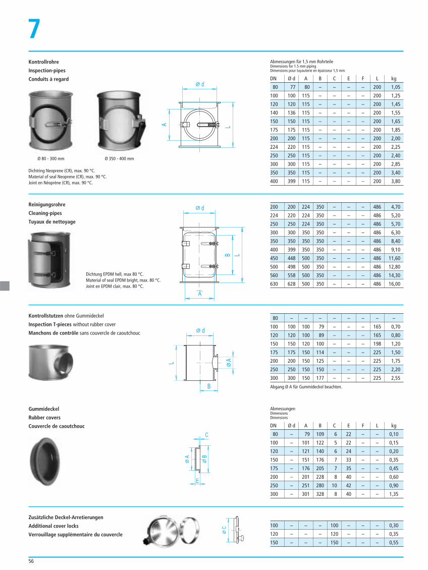
56
Kontrollrohre
Inspection-pipes
Conduits à regard
7
80 77 80 – – – – 200 1,05
100 100 115 – – – – 200 1,25
120 120 115 – – – – 200 1,45
140 136 115 – – – – 200 1,55
150 150 115 – – – – 200 1,65
175 175 115 – – – – 200 1,85
200 200 115 – – – – 200 2,00
224 220 115 – – – – 200 2,25
250 250 115 – – – – 200 2,40
300 300 115 – – – – 200 2,85
350 350 115 – – – – 200 3,40
400 399 115 – – – – 200 3,80
Abmessungen für 1,5 mm RohrteileDimensions for 1.5 mm pipingDimensions pour tuyauterie en épaisseur 1,5 mm
AbmessungenDimensionsDimensions
DN Ø d A B C E F L kg
DN Ø d A B C E F L kg
200 200 224 350 – – – 486 4,70
224 220 224 350 – – – 486 5,20
250 250 224 350 – – – 486 5,70
300 300 350 350 – – – 486 6,30
350 350 350 350 – – – 486 8,40
400 399 350 350 – – – 486 9,10
450 448 500 350 – – – 486 11,60
500 498 500 350 – – – 486 12,80
560 558 500 350 – – – 486 14,30
630 628 500 350 – – – 486 16,00
80 – – – – – – – –
100 100 100 79 – – – 165 0,70
120 120 100 89 – – – 165 0,80
150 150 120 100 – – – 198 1,20
175 175 150 114 – – – 225 1,50
200 200 150 125 – – – 225 1,75
250 250 150 150 – – – 225 2,20
300 300 150 177 – – – 225 2,55
80 – 79 109 6 22 – – 0,10
100 – 101 122 5 22 – – 0,15
120 – 121 140 6 24 – – 0,20
150 – 151 176 7 33 – – 0,35
175 – 176 205 7 35 – – 0,45
200 – 201 228 8 40 – – 0,60
250 – 251 280 10 42 – – 0,90
300 – 301 328 8 40 – – 1,35
100 – – – 100 – – – 0,30
120 – – – 120 – – – 0,35
150 – – – 150 – – – 0,55
d
LA
Reinigungsrohre
Cleaning-pipes
Tuyaux de nettoyage
Kontrollstutzen ohne Gummideckel
Inspection T-pieces without rubber cover
Manchons de contrôle sans couvercle de caoutchouc
Dichtung EPDM hell, max 80 °C.Material of seal EPDM bright, max. 80 °C.Joint en EPDM clair, max. 80 °C.
d
LB
A
d
B
L
A
C
E
A B
C
Abgang Ø A für Gummideckel beachten.
Gummideckel
Rubber covers
Couvercle de caoutchouc
Zusätzliche Deckel-Arretierungen
Additional cover locks
Verrouillage supplémentaire du couvercle
Dichtring Neoprene (CR), max. 90 °C.Material of seal Neoprene (CR), max. 90 °C.Joint en Néoprène (CR), max. 90 °C.
Ø 80 - 300 mm Ø 350 - 400 mm
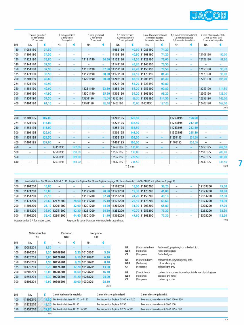
57
7
1,5 mm grundiert 2 mm grundiert 3 mm grundiert 1,5 mm verzinkt 1 mm Chromnickelstahl 1,5 mm Chromnickelstahl 2 mm Chromnickelstahl1.5 mm primed 2 mm primed 3 mm primed 1.5 mm galvanized 1 mm stainless steel 1.5 mm stainless steel 2 mm stainless steel1,5 mm peint 2 mm peint 3 mm peint 1,5 mm galvanisé 1 mm acier inoxydable 1,5 mm acier inoxydable 2 mm acier inoxydable
Nr. € Nr. € Nr. € Nr. € Nr. € Nr. € Nr. €
Nr. € Nr. € Nr. €
Nr. €
DN
DN
DN
2010
80
100
120
140
150
175
200
224
250
300
350
400
11081190 34,50
11101190 34,50
11121190 35,80
11141190 37,90
11151190 37,90
11171190 39,50
11201190 40,80
11221190 42,90
11251190 42,90
11301190 44,90
11351190 57,50
11401190 61,10
– –
– –
– –
– –
– –
– –
– –
– –
– –
– –
– –
– –
– –
– –
13121190 54,50
– –
13151190 57,60
13171190 58,30
13201190 60,90
– –
13251190 63,50
13301190 65,20
13351190 76,50
13401190 83,10
11082190 40,30
11102190 40,30
11122190 42,20
11142190 45,20
11152190 45,20
11172190 47,10
11202190 48,10
11222190 52,20
11252190 52,20
11302190 54,20
11352190 69,30
11402190 75,00
11083190 74,20
11103190 74,20
11123190 76,00
11143190 78,50
11153190 78,50
11173190 81,40
11203190 85,40
11223190 90,80
11253190 90,80
11303190 98,20
11353190 114,50
11403190 127,00
– –
– –
– –
– –
– –
– –
– –
– –
– –
– –
– –
– –
– –
12103190 90,00
12123190 91,80
– –
12153190 95,70
12173190 99,00
12203190 105,00
– –
12253190 114,50
12303190 128,00
12353190 146,00
12403190 167,00
2020
11201195 107,00
11221195 115,00
11251195 115,00
11301195 122,00
11351195 129,50
11401195 137,00
– –
– –
– –
– –
– –
– –
– –
– –
– –
– –
12451195 147,00
12501195 158,00
12561195 169,00
12631195 183,50
– –
– –
– –
– –
– –
– –
– –
– –
– –
– –
11202195 128,50
11222195 138,50
11252195 138,50
11302195 146,00
11352195 156,50
11402195 166,00
12452195 *) 185,00
12502195 *) 199,00
12562195 *) 220,50
12632195 *) 234,50
– –
– –
– –
– –
– –
– –
– –
– –
– –
– –
11203195 198,00
11223195 212,50
11253195 212,50
11303195 225,50
11353195 239,50
11403195 252,00
– –
– –
– –
– –
– –
– –
– –
– –
– –
– –
12453195 269,50
12503195 289,00
12563195 309,00
12633195 335,50
200
224
250
300
350
400
450
500
560
630
1040
11101200 16,00
11121200 16,80
11151200 20,10
11171200 23,60
11201200 25,10
11251200 33,00
11301200 39,40
– –
– –
– –
12171200 28,60
12201200 32,00
12251200 42,30
12301200 44,40
– –
13121200 28,60
13151200 32,70
13171200 35,10
13201200 44,70
13251200 54,80
13301200 61,70
11102200 18,00
11122200 19,30
11152200 24,20
11172200 26,10
11202200 31,30
11252200 40,70
11302200 47,60
11103200 39,20
11123200 41,00
11153200 48,10
11173200 63,60
11203200 65,80
11253200 73,30
11303200 77,30
– –
– –
– –
– –
– –
– –
– –
12103200 45,80
12123200 48,90
12153200 62,90
12173200 81,90
12203200 87,70
12253200 92,30
12303200 112,50
80
100
120
150
175
200
250
300
Kontrollstutzen DN 80 siehe T-Stück S. 38. Inspection T-piece DN 80 see T-piece on page 38. Manchons de contrôle DN 80 voir pièces en T page 38.
3030
10085201 3,30
10105201 3,30
10125201 3,80
10155201 4,90
10175201 8,20
10205201 10,00
10255201 14,30
10305201 19,90
– –
10106201 5,30
10126201 6,10
10156201 8,20
10176201 12,20
10206201 16,60
10256201 23,20
10306201 30,00
– –
10108201 5,30
10128201 6,10
10158201 8,40
10178201 13,50
10208201 16,40
10258201 24,00
10308201 28,10
80
100
120
150
175
200
250
300
*) 2 mm
3040
Für Kontrollstutzen Ø 100 und 120 For inspection T-piece Ø 100 and 120 Pour manchons de contrôle Ø 100 et 120
Für Kontrollstutzen Ø 150 For inspection T-piece Ø 150 Pour manchons de contrôle Ø 150
Für Kontrollstutzen Ø 175 bis 300 For inspection T-piece Ø 175 to 300 Pour manchons de contrôle Ø 175 à 300
100
120
150
Natural rubber Perbunan NeopreneNR NBR CR
2 mm galvanisch verzinkt 2 mm electro galvanized 2 mm electro galvanisé
NR (Naturkautschuk) Farbe weiß, physiologisch unbedenklich.NBR (Perbunan) Farbe dunkelgrauCR (Neoprene) Farbe hellgrau
NR (Natural rubber) colour: white, physiologically safe.NBR (Perbunan) colour: dark greyCR (Neoprene) colour: light grey
NR (Caoutchouc) couleur: blanc, sans risque du point de vue physiologique.NBR (Perbunan) couleur: gris foncéCR (Neoprene) couleur: gris clair
Observe outlet Ø A for rubber cover. Respecter la sortie Ø A pour le couvercle de caoutchouc.
11102210 17,80
11122210 18,20
11152210 22,80
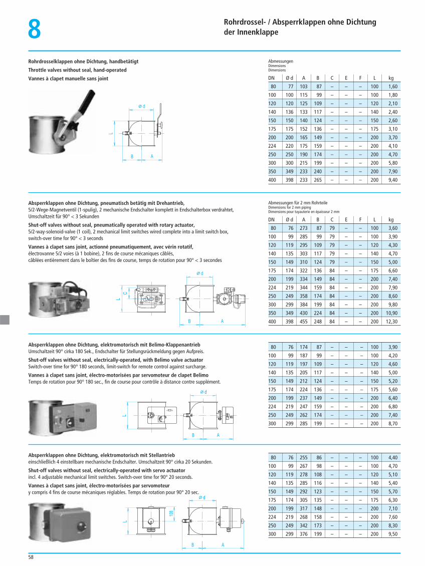
Rohrdrossel- / Absperrklappen ohne Dichtung der Innenklappe
58
Rohrdrosselklappen ohne Dichtung, handbetätigt
Throttle valves without seal, hand-operated
Vannes à clapet manuelle sans joint80 77 103 87 – – – 100 1,60
100 100 115 99 – – – 100 1,80
120 120 125 109 – – – 120 2,10
140 136 133 117 – – – 140 2,40
150 150 140 124 – – – 150 2,60
175 175 152 136 – – – 175 3,10
200 200 165 149 – – – 200 3,70
224 220 175 159 – – – 200 4,10
250 250 190 174 – – – 200 4,70
300 300 215 199 – – – 200 5,80
350 349 233 240 – – – 200 7,90
400 398 233 265 – – – 200 9,40
AbmessungenDimensionsDimensions
DN Ø d A B C E F L kg
80 76 273 87 79 – – 100 3,60
100 99 285 99 79 – – 100 3,90
120 119 295 109 79 – – 120 4,30
140 135 303 117 79 – – 140 4,70
150 149 310 124 79 – – 150 5,00
175 174 322 136 84 – – 175 6,60
200 199 334 149 84 – – 200 7,40
224 219 344 159 84 – – 200 7,90
250 249 358 174 84 – – 200 8,60
300 299 384 199 84 – – 200 9,80
350 349 430 224 84 – – 200 10,90
400 398 455 248 84 – – 200 12,30
Abmessungen für 2 mm RohrteileDimensions for 2 mm pipingDimensions pour tuyauterie en épaisseur 2 mm
DN Ø d A B C E F L kg
d
L
B A
C
dL
B A
L
d
B A
108
L
d
B A
80 76 174 87 – – – 100 3,90
100 99 187 99 – – – 100 4,20
120 119 197 109 – – – 120 4,60
140 135 205 117 – – – 140 5,00
150 149 212 124 – – – 150 5,20
175 174 224 136 – – – 175 5,60
200 199 237 149 – – – 200 6,40
224 219 247 159 – – – 200 6,80
250 249 262 174 – – – 200 7,40
300 299 285 199 – – – 200 8,70
80 76 255 86 – – – 100 4,40
100 99 267 98 – – – 100 4,70
120 119 278 108 – – – 120 5,10
140 135 285 116 – – – 140 5,40
150 149 292 123 – – – 150 5,70
175 174 305 135 – – – 175 6,30
200 199 317 148 – – – 200 7,10
224 219 268 158 – – – 200 7,60
250 249 342 173 – – – 200 8,30
300 299 376 199 – – – 200 9,50
Absperrklappen ohne Dichtung, pneumatisch betätig mit Drehantrieb,5/2-Wege-Magnetventil (1-spulig), 2 mechanische Endschalter komplett in Endschalterbox verdrahtet, Umschaltzeit für 90° < 3 Sekunden
Shut-off valves without seal, pneumatically operated with rotary actuator,5/2-way-solenoid-valve (1 coil), 2 mechanical limit switches wired complete into a limit switch box, switch-over time for 90° < 3 seconds
Vannes à clapet sans joint, actionné pneumatiquement, avec vérin rotatif,électrovanne 5/2 voies (à 1 bobine), 2 fins de course mécaniques câblés, câblées entièrement dans le boîtier des fins de course, temps de rotation pour 90° < 3 secondes
Absperrklappen ohne Dichtung, elektromotorisch mit Belimo-KlappenantriebUmschaltzeit 90° cirka 180 Sek., Endschalter für Stellungsrückmeldung gegen Aufpreis.
Shut-off valves without seal, electrically-operated, with Belimo valve actuatorSwitch-over time for 90° 180 seconds, limit-switch for remote control against surcharge.
Vannes à clapet sans joint, électro-motorisées par servomoteur de clapet Belimo Temps de rotation pour 90° 180 sec., fin de course pour contrôle à distance contre supplément.
Absperrklappen ohne Dichtung, elektromotorisch mit Stellantriebeinschließlich 4 einstellbare mechanische Endschalter. Umschaltzeit 90° cirka 20 Sekunden.
Shut-off valves without seal, electrically-operated with servo actuatorincl. 4 adjustable mechanical limit switches. Switch-over time for 90° 20 seconds.
Vannes à clapet sans joint, électro-motorisées par servomoteury compris 4 fins de course mécaniques réglables. Temps de rotation pour 90° 20 sec.
8
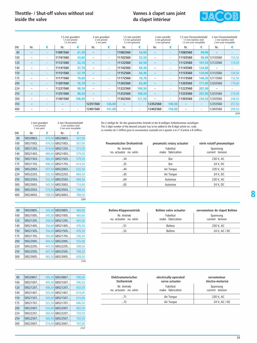
Throttle- / Shut-off valves without seal inside the valve
Vannes à clapet sans jointdu clapet intérieur
59
8
..34 Bar 230 V, AC
..35 Bar 24 V, DC
..44 Air Torque 230 V, AC
..45 Air Torque 24 V, DC
..64 Automax 230 V, AC
..65 Automax 24 V, DC
1,5 mm grundiert 2 mm grundiert 1,5 mm verzinkt 2 mm verzinkt 1,5 mm Chromnickelstahl 2 mm Chromnickelstahl1.5 mm primed 2 mm primed 1.5 mm galvanized 2 mm galvanized 1.5 mm stainless steel 2 mm stainless steel1,5 mm peint 2 mm peint 1,5 mm galvanisé 2 mm galvanisé 1,5 mm acier inoxydable 2 mm acier inoxydable
2 mm grundiert 2 mm Chromnickelstahl2 mm primed 2 mm stainless steel2 mm peint 2 mm acier inoxydable
Nr. € Nr. € Nr. € Nr. € Nr. € Nr. € Nr. €
Nr. € Nr. €
DN
DN
2070
80
100
120
140
150
175
200
224
250
300
350
400
58520803.. 470,50
58521003.. 470,50
58521203.. 474,00
58521403.. 480,00
58521503.. 480,00
58521703.. 496,50
58522003.. 507,50
58522203.. 532,50
58522503.. 532,50
58523003.. 545,50
58523503.. 570,50
58524003.. 598,50
68520803.. 567,00
68521003.. 567,00
68521203.. 573,50
68521403.. 579,50
68521503.. 579,50
68521703.. 614,50
68522003.. 632,50
68522203.. 684,50
68522503.. 684,50
68523003.. 710,00
68523503.. 748,50
68524003.. 788,50
80
100
120
140
150
175
200
224
250
300
350
400
58520807.. 495,00
58521007.. 495,00
58521207.. 498,50
58521407.. 505,00
58521507.. 505,00
58521707.. 522,50
58522007.. 534,00
58522207.. 560,50
58522507.. 560,50
58523007.. 574,00
68520807.. 596,50
68521007.. 596,50
68521207.. 603,50
68521407.. 610,00
68521507.. 610,00
68521707.. 646,50
68522007.. 665,50
68522207.. 720,50
68522507.. 720,50
68523007.. 747,00
80
100
120
140
150
175
200
224
250
300
58520805.. 345,00
58521005.. 345,00
58521205.. 348,50
58521405.. 356,00
58521505.. 356,00
58521705.. 393,00
58522005.. 404,50
58522205.. 447,50
58522505.. 447,50
58523005.. 465,50
68520805.. 460,00
68521005.. 460,00
68521205.. 465,00
68521405.. 476,50
68521505.. 476,50
68521705.. 536,50
68522005.. 555,00
68522205.. 598,50
68522505.. 598,50
68523005.. 639,50
80
100
120
140
150
175
200
224
250
300
– –
– –
– –
– –
– –
– –
– –
– –
– –
– –
– –
– –
11081560 41,30
11101560 43,60
11121560 52,10
11141560 57,70
11151560 57,70
11171560 70,60
11201560 76,70
11221560 98,50
11251560 98,50
11301560 108,00
– –
– –
– –
– –
– –
– –
– –
– –
– –
– –
– –
– –
12351560 126,00
12401560 141,00
11082560 54,00
11102560 55,50
11122560 64,50
11142560 69,30
11152560 69,30
11172560 76,70
11202560 83,40
11222560 108,50
11252560 108,50
11302560 121,50
– –
– –
– –
– –
– –
– –
– –
– –
– –
– –
– –
– –
12352560 140,50
12402560 156,00
11083560 99,00
11103560 99,00
11123560 107,50
11143560 124,00
11153560 124,00
11173560 140,50
11203560 171,00
11223560 207,00
11253560 207,00
11303560 234,50
– –
– –
– –
12103560 105,50
12123560 114,50
– –
12153560 130,50
12173560 152,50
12203560 179,00
– –
12253560 219,00
12303560 248,50
12353560 257,50
12403560 299,50
Die 2-stellige Nr. für den gewünschten Antrieb ist der 8-stelligen Artikelnummer anzufügen.The 2-digit number of the desired actuator has to be added to the 8-digit article-no. code.Le nombre de 2 chiffres pour le servomoteur souhaité est à ajouter à le n° d’article à 8 chiffres.
Pneumatischer Drehantrieb pneumatic rotary actuator vérin rotatif pneumatique
Nr. Antrieb Fabrikat Spannungno. actuator no. vérin make fabrication current tension
..51 Belimo 230 V, AC
..52 Belimo 24 V, AC / DC
Belimo-Klappenantrieb Belimo valve actuator servomoteur de clapet Belimo
Nr. Antrieb Fabrikat Spannungno. actuator no. vérin make fabrication current tension
..71 Air Torque 230 V, AC
..72 Air Torque 24 V, AC / DC
Elektromotorischer electrically-operated servomoteurStellantrieb servo actuator électro-motorisé
Nr. Antrieb Fabrikat Spannungno. actuator no. vérin make fabrication current tension
2095
2105
2107
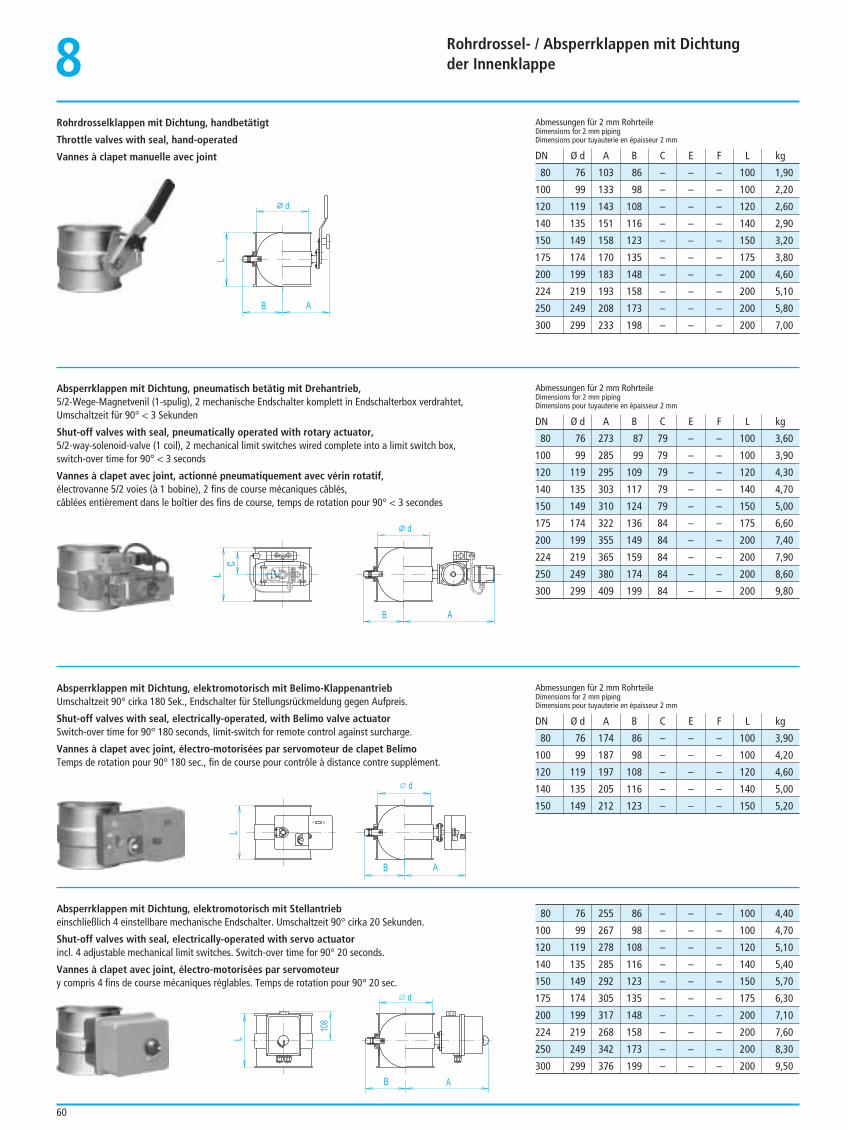
8 Rohrdrossel- / Absperrklappen mit Dichtung der Innenklappe
60
80 76 103 86 – – – 100 1,90
100 99 133 98 – – – 100 2,20
120 119 143 108 – – – 120 2,60
140 135 151 116 – – – 140 2,90
150 149 158 123 – – – 150 3,20
175 174 170 135 – – – 175 3,80
200 199 183 148 – – – 200 4,60
224 219 193 158 – – – 200 5,10
250 249 208 173 – – – 200 5,80
300 299 233 198 – – – 200 7,00
Abmessungen für 2 mm RohrteileDimensions for 2 mm pipingDimensions pour tuyauterie en épaisseur 2 mm
Abmessungen für 2 mm RohrteileDimensions for 2 mm pipingDimensions pour tuyauterie en épaisseur 2 mm
Abmessungen für 2 mm RohrteileDimensions for 2 mm pipingDimensions pour tuyauterie en épaisseur 2 mm
DN Ø d A B C E F L kg
DN Ø d A B C E F L kg
DN Ø d A B C E F L kg
80 76 273 87 79 – – 100 3,60
100 99 285 99 79 – – 100 3,90
120 119 295 109 79 – – 120 4,30
140 135 303 117 79 – – 140 4,70
150 149 310 124 79 – – 150 5,00
175 174 322 136 84 – – 175 6,60
200 199 355 149 84 – – 200 7,40
224 219 365 159 84 – – 200 7,90
250 249 380 174 84 – – 200 8,60
300 299 409 199 84 – – 200 9,80
L
C
d
B A
d
B A
L
L
d
B A
d
B A
L
108
80 76 174 86 – – – 100 3,90
100 99 187 98 – – – 100 4,20
120 119 197 108 – – – 120 4,60
140 135 205 116 – – – 140 5,00
150 149 212 123 – – – 150 5,20
80 76 255 86 – – – 100 4,40
100 99 267 98 – – – 100 4,70
120 119 278 108 – – – 120 5,10
140 135 285 116 – – – 140 5,40
150 149 292 123 – – – 150 5,70
175 174 305 135 – – – 175 6,30
200 199 317 148 – – – 200 7,10
224 219 268 158 – – – 200 7,60
250 249 342 173 – – – 200 8,30
300 299 376 199 – – – 200 9,50
Rohrdrosselklappen mit Dichtung, handbetätigt
Throttle valves with seal, hand-operated
Vannes à clapet manuelle avec joint
Absperrklappen mit Dichtung, pneumatisch betätig mit Drehantrieb,5/2-Wege-Magnetvenil (1-spulig), 2 mechanische Endschalter komplett in Endschalterbox verdrahtet,Umschaltzeit für 90° < 3 Sekunden
Shut-off valves with seal, pneumatically operated with rotary actuator,5/2-way-solenoid-valve (1 coil), 2 mechanical limit switches wired complete into a limit switch box, switch-over time for 90° < 3 seconds
Vannes à clapet avec joint, actionné pneumatiquement avec vérin rotatif,électrovanne 5/2 voies (à 1 bobine), 2 fins de course mécaniques câblés, câblées entièrement dans le boîtier des fins de course, temps de rotation pour 90° < 3 secondes
Absperrklappen mit Dichtung, elektromotorisch mit Belimo-KlappenantriebUmschaltzeit 90° cirka 180 Sek., Endschalter für Stellungsrückmeldung gegen Aufpreis.
Shut-off valves with seal, electrically-operated, with Belimo valve actuatorSwitch-over time for 90° 180 seconds, limit-switch for remote control against surcharge.
Vannes à clapet avec joint, électro-motorisées par servomoteur de clapet Belimo Temps de rotation pour 90° 180 sec., fin de course pour contrôle à distance contre supplément.
Absperrklappen mit Dichtung, elektromotorisch mit Stellantriebeinschließlich 4 einstellbare mechanische Endschalter. Umschaltzeit 90° cirka 20 Sekunden.
Shut-off valves with seal, electrically-operated with servo actuatorincl. 4 adjustable mechanical limit switches. Switch-over time for 90° 20 seconds.
Vannes à clapet avec joint, électro-motorisées par servomoteury compris 4 fins de course mécaniques réglables. Temps de rotation pour 90° 20 sec.
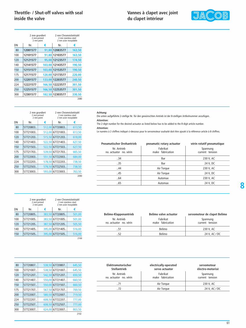
8
Throttle- / Shut-off valves with seal inside the valve
Vannes à clapet avec joint du clapet intérieur
61
..34 Bar 230 V, AC
..35 Bar 24 V, DC
..44 Air Torque 230 V, AC
..45 Air Torque 24 V, DC
..64 Automax 230 V, AC
..65 Automax 24 V, DC
57720803.. 512,00
57721003.. 512,00
57721203.. 515,50
57721403.. 522,50
57721503.. 522,50
57721703.. 539,50
57722003.. 551,50
57722203.. 578,50
57722503.. 578,50
57723003.. 593,00
67720803.. 613,50
67721003.. 613,50
67721203.. 618,00
67721403.. 627,50
67721503.. 627,50
67721703.. 665,50
67722003.. 684,00
67722203.. 738,50
67722503.. 738,50
67723003.. 763,50
80
100
120
140
150
175
200
224
250
300
57720807.. 538,50
57721007.. 538,50
57721207.. 542,50
57721407.. 550,00
57721507.. 550,00
57721707.. 567,50
57722007.. 580,50
57722207.. 608,50
57722507.. 608,50
57723007.. 624,00
67720807.. 645,50
67721007.. 645,50
67721207.. 650,50
67721407.. 660,50
67721507.. 660,50
67721707.. 700,50
67722007.. 719,50
67722207.. 777,00
67722507.. 777,00
67723007.. 803,50
80
100
120
140
150
175
200
224
250
300
57720805.. 383,50
57721005.. 383,50
57721205.. 387,50
57721405.. 395,00
57721505.. 395,00
67720805.. 501,00
67721005.. 501,00
67721205.. 505,50
67721405.. 516,00
67721505.. 516,00
80
100
120
140
150
Achtung: Die unten aufgeführte 2-stellige Nr. für den gewünschten Antrieb ist der 8-stelligen Artikelnummer anzufügen.
Attention:The 2-digit number for the desired actuator as listed below has to be added to the 8-digit article number.
Attention: Le numéro à 2 chiffres indiqué ci-dessous pour le servomoteur souhaité doit être ajouté à la référence article à 8 chiffres.
Pneumatischer Drehantrieb pneumatic rotary actuator vérin rotatif pneumatique
Nr. Antrieb Fabrikat Spannungno. actuator no. vérin make fabrication current tension
..51 Belimo 230 V, AC
..52 Belimo 24 V, AC / DC
Belimo-Klappenantrieb Belimo valve actuator servomoteur de clapet Belimo
Nr. Antrieb Fabrikat Spannungno. actuator no. vérin make fabrication current tension
2090
2 mm grundiert 2 mm Chromnickelstahl2 mm primed 2 mm stainless steel2 mm peint 2 mm acier inoxydable
2 mm grundiert 2 mm Chromnickelstahl2 mm primed 2 mm stainless steel2 mm peint 2 mm acier inoxydable
2 mm grundiert 2 mm Chromnickelstahl2 mm primed 2 mm stainless steel2 mm peint 2 mm acier inoxydable
Nr. € Nr. €
Nr. € Nr. €
Nr. € Nr. €
DN
DN
DN
12081577 91,80
12101577 91,80
12121577 95,00
12141577 103,00
12151577 103,00
12171577 120,00
12201577 133,00
12221577 166,50
12251577 166,50
12301577 182,50
12083577 163,50
12103577 163,50
12123577 174,50
12143577 190,50
12153577 190,50
12173577 220,00
12203577 240,50
12223577 301,50
12253577 301,50
12303577 330,50
80
100
120
140
150
175
200
224
250
3002080
2100
2102
..71 Air Torque 230 V, AC
..72 Air Torque 24 V, AC / DC
Elektromotorischer electrically-operated servomoteurStellantrieb servo actuator électro-motorisé
Nr. Antrieb Fabrikat Spannungno. actuator no. vérin make fabrication current tension
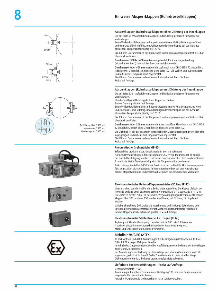
Hinweise Absperrklappen (Rohrdrosselklappen)
62
8Absperrklappen (Rohrdrosselklappen) ohne Dichtung der InnenklappeDie auf Seite 58-59 aufgeführten Klappen sind beidseitig gebördelt für Spannring-verbindungen.Beide Wellendurchführungen sind abgedichtet mit einer O-Ring-Dichtung aus Vitonund einer aus EPDM-leitfähig, um Aufladungen der Innenklappe auf das Gehäuseabzuleiten. Temperaturbeständig bis 120 °C.Bis 300 mm Durchmesser ist die Klappe nach außen explosionsdruckstoßfest bis 3 barÜberdruck zertifiziert.Durchmesser 350 bis 400 mm können gebördelt für Spannringverbindung (nicht druckstoßfest) oder mit Losflanschen geliefert werden.Durchmesser über 400 mm werden mit Losflansch nach DIN 24154, T2 ausgeführt,jedoch ohne Gegenflansch. Flansche siehe Seite 102. Die Wellen sind kugelgelagertund mit einem O-Ring aus Viton abgedichtet.Bis 630 mm Durchmesser nach außen explosionsdruckstoßfest bis 3 bar.Preise auf Anfrage.
Viton
EPDM
Silikon
EPDM
Viton
Richtlinie 94/9/EG (ATEX)Je nach Antrieb sind ATEX-Ausführungen für die Umgebung der Klappen in Ex II 2/3G/D c IIB T4 X gegen Mehrpreis lieferbar.Innerhalb des Klappengehäuses sind bei Ausführungen ohne Dichtung der InnenklappeZone 0 und 20 zugelassen.Bei Ausführungen mit Dichtung der Innenklappe aus Silikon ist im Inneren Zone 20zugelassen, jedoch nicht Zone 0. Sollte Zone 0 erforderlich sein, sind leitfähigeDichtungen erforderlich, die keine Lebensmittelqualität aufweisen.
Lieferbare Sonderausführungen – Preise auf Anfrage.Gehäusewerkstoff 1.4571.Ausführungen für höhere Temperaturen, Betätigung 100 mm vom Gehäuse entferntangebracht für bauseitige Isolierung.Antriebe, Magnetventile und Endschalter nach Kundenvorgaben.
Absperrklappen (Rohrdrosselklappen) mit Dichtung der InnenklappeDie auf Seite 60-61 aufgeführten Klappen sind beidseitig gebördelt für Spannring-verbindungen. Standardmäßig mit Dichtung der Innenklappe aus Silikon.Andere Gummiqualitäten auf Anfrage.Beide Wellendurchführungen sind abgedichtet mit einer O-Ring-Dichtung aus Vitonund einer aus EPDM-leitfähig, um Aufladungen der Innenklappe auf das Gehäuseabzuleiten. Temperaturbeständig bis 120 °C.Bis 300 mm Durchmesser ist die Klappe nach außen explosionsdruckstoßfest bis 3 barÜberdruck zertifiziert.Durchmesser über 300 mm werden mit angeschweißten Flanschen nach DIN 24154,T2 ausgeführt, jedoch ohne Gegenflansch. Flansche siehe Seite 102.Die Dichtung ist auf der gesamten Innenfläche der Klappe angebracht. Die Wellen sindkugelgelagert und mit einem O-Ring aus Viton abgedichtet.Bis 630 mm Durchmesser nach außen explosionsdruckstoßfest bis 3 bar. Preise auf Anfrage.
Pneumatische Drehantriebe (IP 65)Erforderliche Druckluft 5 bar. Umschaltzeit für 90° < 3 Sekunden.Auf dem Drehantrieb ist ein federrückgeführtes 5/2-Wege-Magnetventil (1-spulig) mit Handhilfsbetätigung montiert, mit einem Druckluftanschluss für Gewebeschläuche8 mm lichte Weite. Standardmäßig wird die Klappe stromlos geschlossen.Endschalter potentialfrei 4-250 V mit Goldkontakten prellfrei für SPS-Steuerungen undfür Stromstärken bis 5 A geeignet, in einer Endschalterbox auf dem Antrieb ange-bracht. Magnetventil und Endschalter auf Klemmen in Endschalterbox verdrahtet.
Elektromotorische Belimo-Klappenantriebe (30 Nm, IP 42)Überlastsicher, standardmäßig ohne Endschalter ausgeführt. Die Klappe bleibt in derjeweilige Endlage unter Spannung stehen. Verbrauch 24 V = 3 Watt, 230 V = 10 W.Umschaltzeit für 90° cirka 180 Sekunden. Wegen des geringen Drehmoments könnenKlappen über 300 mm bzw. 150 mm bei Ausführung mit Dichtung nicht geliefertwerden.Variabel einstellbare Endschalter zur Abschaltung und Stellungsrückmeldung oderPotentiometer gegen Mehrpreis lieferbar. Absperrklappen mit stetig regelbaremBelimo-Klappenantrieb, externes Signal 0-10 V, auf Anfrage.
Elektromotorische Stellantriebe Air Torque (IP 65)1-phasig, mit Handnotbetätigung. Umschaltzeit für 90° cirka 20 Sekunden.4 variabel einstellbare mechanische Endschalter im Antrieb integriert.Motor und Endschalter auf Klemmen verdrahtet.
Ausführung über Ø 300 mmVersion over Ø 300 mm
Version sup. au Ø 300 mm
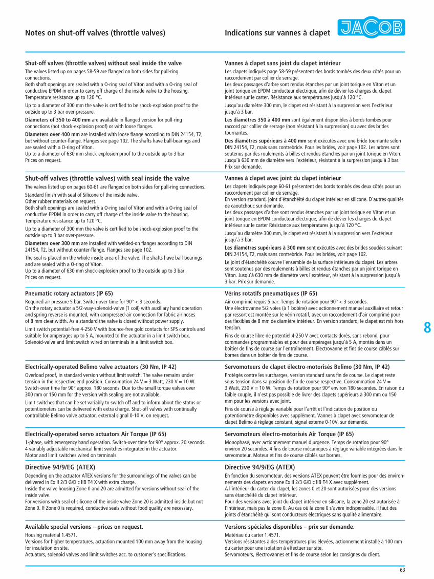
Notes on shut-off valves (throttle valves) Indications sur vannes à clapet
63
8
Shut-off valves (throttle valves) without seal inside the valveThe valves listed up on pages 58-59 are flanged on both sides for pull-ringconnections.Both shaft openings are sealed with a O-ring seal of Viton and with a O-ring seal ofconductive EPDM in order to carry off charge of the inside valve to the housing.Temperature resistance up to 120 °C.Up to a diameter of 300 mm the valve is certified to be shock-explosion proof to theoutside up to 3 bar over-pressure.Diameters of 350 to 400 mm are available in flanged version for pull-ringconnections (not shock-explosion proof) or with loose flanges.Diameters over 400 mm are installed with loose flange according to DIN 24154, T2,but without counter-flange. Flanges see page 102. The shafts have ball-bearings andare sealed with a O-ring of Viton.Up to a diameter of 630 mm shock-explosion proof to the outside up to 3 bar.Prices on request.
Directive 94/9/EG (ATEX)Depending on the actuator ATEX versions for the surroundings of the valves can bedelivered in Ex II 2/3 G/D c IIB T4 X with extra charge.Inside the valve housing Zone 0 and 20 are admitted for versions without seal of theinside valve.For versions with seal of silicone of the inside valve Zone 20 is admitted inside but notZone 0. If Zone 0 is required, conductive seals without food quality are necessary.
Available special versions – prices on request.Housing material 1.4571.Versions for higher temperatures, actuation mounted 100 mm away from the housingfor insulation on site.Actuators, solenoid valves and limit switches acc. to customer's specifications.
Vannes à clapet sans joint du clapet intérieurLes clapets indiqués page 58-59 présentent des bords tombés des deux côtés pour unraccordement par collier de serrage.Les deux passages d'arbre sont rendus étanches par un joint torique en Viton et unjoint torique en EPDM conducteur électrique, afin de dévier les charges du clapetintérieur sur le carter. Résistance aux températures jusqu'à 120 °C.Jusqu'au diamètre 300 mm, le clapet est résistant à la surpression vers l'extérieur jusqu'à 3 bar.Les diamètres 350 à 400 mm sont également disponibles à bords tombés pourraccord par collier de serrage (non résistant à la surpression) ou avec des bridestournantes.Des diamètres supérieurs à 400 mm sont exécutés avec une bride tournante selonDIN 24154, T2, mais sans contrebride. Pour les brides, voir page 102. Les arbres sontsoutenus par des roulements à billes et rendus étanches par un joint torique en Viton.Jusqu'à 630 mm de diamètre vers l'extérieur, résistant à la surpression jusqu'à 3 bar.Prix sur demande.
Shut-off valves (throttle valves) with seal inside the valveThe valves listed up on pages 60-61 are flanged on both sides for pull-ring connections.Standard finish with seal of Silicone of the inside valve.Other rubber materials on request.Both shaft openings are sealed with a O-ring seal of Viton and with a O-ring seal ofconductive EPDM in order to carry off charge of the inside valve to the housing.Temperature resistance up to 120 °C.Up to a diameter of 300 mm the valve is certified to be shock-explosion proof to theoutside up to 3 bar over-pressure.Diameters over 300 mm are installed with welded-on flanges according to DIN24154, T2, but without counter-flange. Flanges see page 102.The seal is placed on the whole inside area of the valve. The shafts have ball-bearingsand are sealed with a O-ring of Viton. Up to a diameter of 630 mm shock-explosion proof to the outside up to 3 bar.Prices on request.
Vannes à clapet avec joint du clapet intérieurLes clapets indiqués page 60-61 présentent des bords tombés des deux côtés pour unraccordement par collier de serrage. En version standard, joint d'étanchéité du clapet intérieur en silicone. D'autres qualitésde caoutchouc sur demande.Les deux passages d'arbre sont rendus étanches par un joint torique en Viton et unjoint torique en EPDM conducteur électrique, afin de dévier les charges du clapetintérieur sur le carter Résistance aux températures jusqu'à 120 °C.Jusqu'au diamètre 300 mm, le clapet est résistant à la surpression vers l'extérieurjusqu'à 3 bar.Les diamètres supérieurs à 300 mm sont exécutés avec des brides soudées suivantDIN 24154, T2, mais sans contrebride. Pour les brides, voir page 102.Le joint d'étanchéité couvre l'ensemble de la surface intérieure du clapet. Les arbressont soutenus par des roulements à billes et rendus étanches par un joint torique enViton. Jusqu'à 630 mm de diamètre vers l'extérieur, résistant à la surpression jusqu'à 3 bar. Prix sur demande.
Pneumatic rotary actuators (IP 65)Required air pressure 5 bar. Switch-over time for 90° < 3 seconds.On the rotary actuator a 5/2-way-solenoid-valve (1 coil) with auxiliary hand operationand spring reverse is mounted, with compressed-air connection for fabric air hoses of 8 mm clear width. As a standard the valve is closed without power supply.Limit switch potential-free 4-250 V with bounce-free gold contacts for SPS controls andsuitable for amperages up to 5 A, mounted to the actuator in a limit switch box.Solenoid-valve and limit switch wired on terminals in a limit switch box.
Vérins rotatifs pneumatiques (IP 65)Air comprimé requis 5 bar. Temps de rotation pour 90° < 3 secondes.Une électrovanne 5/2 voies (à 1 bobine) avec actionnement manuel auxiliaire et retourpar ressort est montée sur le vérin rotatif, avec un raccordement d'air comprimé pourdes flexibles de 8 mm de diamètre intérieur. En version standard, le clapet est mis horstension.Fins de course libre de potentiel 4-250 V avec contacts dorés, sans rebond, pourcommandes programmables et pour des ampérages jusqu'à 5 A, montés dans unboîtier de fins de course sur l'entraînement. Electrovanne et fins de course câblés surbornes dans un boîtier de fins de course.
Electrically-operated Belimo valve actuators (30 Nm, IP 42)Overload proof, in standard version without limit switch. The valve remains undertension in the respective end position. Consumption 24 V = 3 Watt, 230 V = 10 W.Switch-over time for 90° approx. 180 seconds. Due to the small torque valves over 300 mm or 150 mm for the version with sealing are not available.Limit switches that can be set variably to switch off and to inform about the status orpotentiometers can be delivered with extra charge. Shut-off valves with continuallycontrollable Belimo valve actuator, external signal 0-10 V, on request.
Servomoteurs de clapet électro-motorisés Belimo (30 Nm, IP 42)Protégés contre les surcharges, version standard sans fin de course. Le clapet restesous tension dans sa position de fin de course respective. Consommation 24 V = 3 Watt, 230 V = 10 W. Temps de rotation pour 90° environ 180 secondes. En raison dufaible couple, il n'est pas possible de livrer des clapets supérieurs à 300 mm ou 150mm pour les versions avec joint. Fins de course à réglage variable pour l'arrêt et l'indication de position oupotentiomètre disponibles avec supplément. Vannes à clapet avec servomoteur declapet Belimo à réglage constant, signal externe 0-10V, sur demande.
Electrically-operated servo actuators Air Torque (IP 65)1-phase, with emergency hand operation. Switch-over time for 90° approx. 20 seconds.4 variably adjustable mechanical limit switches integrated in the actuator.Motor and limit switches wired on terminals.
Servomoteurs électro-motorisés Air Torque (IP 65)Monophasé, avec actionnement manuel d'urgence. Temps de rotation pour 90°environ 20 secondes. 4 fins de course mécaniques à réglage variable intégrées dans leservomoteur. Moteur et fins de course câblés sur bornes.
Directive 94/9/EG (ATEX)En fonction du servomoteur, des versions ATEX peuvent être fournies pour des environ-nements des clapets en zone Ex II 2/3 G/D c IIB T4 X avec supplément.A l'intérieur du carter du clapet, les zones 0 et 20 sont autorisées pour des versionssans étanchéité du clapet intérieur.Pour des versions avec joint du clapet intérieur en silicone, la zone 20 est autorisée àl'intérieur, mais pas la zone 0. Au cas où la zone 0 s'avère indispensable, il faut desjoints d'étanchéité qui sont conducteurs électriques sans qualité alimentaire.
Versions spéciales disponibles – prix sur demande.Matériau du carter 1.4571.Versions résistantes à des températures plus élevées, actionnement installé à 100 mmdu carter pour une isolation à effectuer sur site.Servomoteurs, électrovannes et fins de course selon les consignes du client.
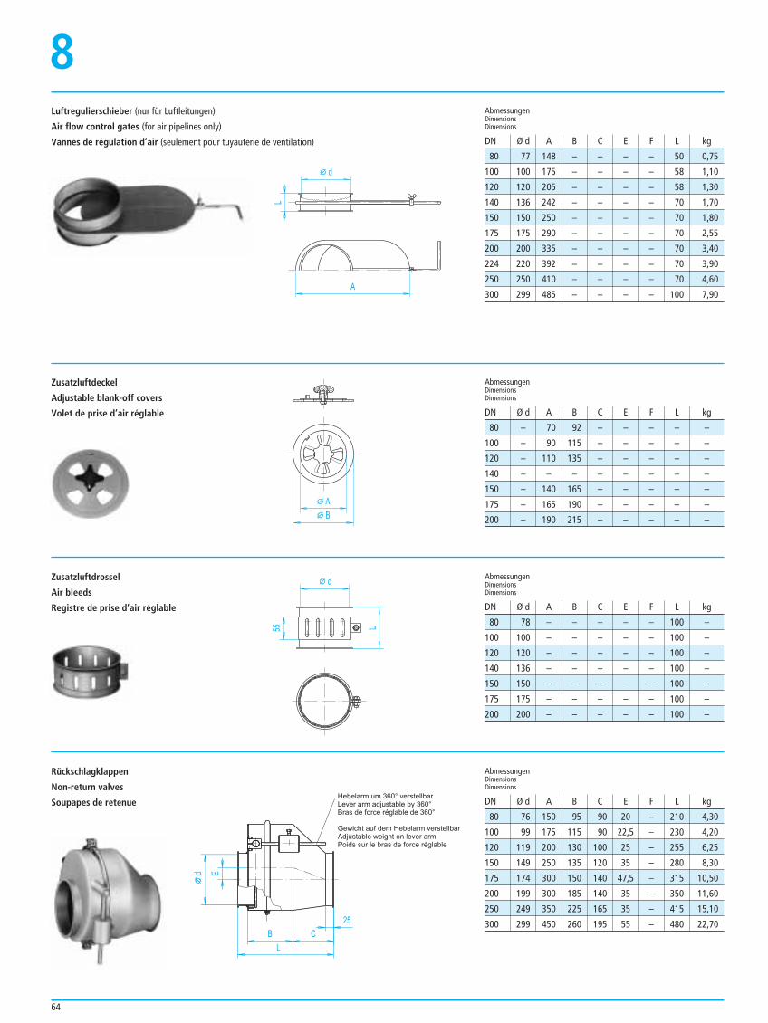
64
Luftregulierschieber (nur für Luftleitungen)
Air flow control gates (for air pipelines only)
Vannes de régulation d’air (seulement pour tuyauterie de ventilation)
8
80 77 148 – – – – 50 0,75
100 100 175 – – – – 58 1,10
120 120 205 – – – – 58 1,30
140 136 242 – – – – 70 1,70
150 150 250 – – – – 70 1,80
175 175 290 – – – – 70 2,55
200 200 335 – – – – 70 3,40
224 220 392 – – – – 70 3,90
250 250 410 – – – – 70 4,60
300 299 485 – – – – 100 7,90
AbmessungenDimensionsDimensions
AbmessungenDimensionsDimensions
AbmessungenDimensionsDimensions
AbmessungenDimensionsDimensions
DN Ø d A B C E F L kg
DN Ø d A B C E F L kg
DN Ø d A B C E F L kg
DN Ø d A B C E F L kg
d
L
A
Zusatzluftdeckel
Adjustable blank-off covers
Volet de prise d’air réglable
A
B
80 – 70 92 – – – – –
100 – 90 115 – – – – –
120 – 110 135 – – – – –
140 – – – – – – – –
150 – 140 165 – – – – –
175 – 165 190 – – – – –
200 – 190 215 – – – – –
Zusatzluftdrossel
Air bleeds
Registre de prise d’air réglable
d
55 L
80 78 – – – – – 100 –
100 100 – – – – – 100 –
120 120 – – – – – 100 –
140 136 – – – – – 100 –
150 150 – – – – – 100 –
175 175 – – – – – 100 –
200 200 – – – – – 100 –
Rückschlagklappen
Non-return valves
Soupapes de retenue
LB C
25
E
Hebelarm um 360° verstellbar
Gewicht auf dem Hebelarm verstellbar
Lever arm adjustable by 360°Bras de force réglable de 360°
Adjustable weight on lever armPoids sur le bras de force réglable
d
80 76 150 95 90 20 – 210 4,30
100 99 175 115 90 22,5 – 230 4,20
120 119 200 130 100 25 – 255 6,25
150 149 250 135 120 35 – 280 8,30
175 174 300 150 140 47,5 – 315 10,50
200 199 300 185 140 35 – 350 11,60
250 249 350 225 165 35 – 415 15,10
300 299 450 260 195 55 – 480 22,70
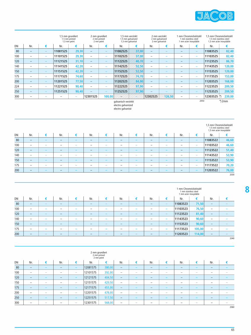
65
8
1,5 mm grundiert 2 mm grundiert 1,5 mm verzinkt 2 mm verzinkt 1 mm Chromnickelstahl 1,5 mm Chromnickelstahl1.5 mm primed 2 mm primed 1.5 mm galvanized 2 mm galvanized 1 mm stainless steel 1.5 mm stainless steel1,5 mm peint 2 mm peint 1,5 mm galvanisé 2 mm galvanisé 1 mm acier inoxydable 1,5 mm acier inoxydable
1,5 mm Chromnickelstahl1.5 mm stainless steel
1,5 mm acier inoxydable
1 mm Chromnickelstahl1 mm stainless steel
1 mm acier inoxydable
2 mm grundiert2 mm primed2 mm peint
– –
– –
– –
– –
– –
– –
– –
– –
– –
– –
11081525 29,30
11101525 29,30
11121525 31,10
11141525 42,20
11151525 42,20
11171525 74,60
11201525 77,50
11221525 90,40
11251525 90,40
– –
– –
– –
– –
– –
– –
– –
– –
– –
– –
12301525 100,00
– –
– –
– –
– –
– –
– –
– –
– –
– –
– –
11083525 82,40
11103525 82,40
11123525 86,70
11143525 120,00
11153525 120,00
11173525 153,00
11203525 168,00
11223525 209,50
11253525 209,50
12303525 *) 239,00
Nr. € Nr. € Nr. € Nr. € Nr. € Nr. € Nr. €
Nr. € Nr. € Nr. € Nr. € Nr. € Nr. € Nr. €
Nr. € Nr. € Nr. € Nr. € Nr. € Nr. € Nr. €
Nr. € Nr. € Nr. € Nr. € Nr. € Nr. € Nr. €
DN
DN
DN
DN
2050
80
100
120
140
150
175
200
224
250
300
*) 2mm
2030
– –
– –
– –
– –
– –
– –
– –
– –
– –
– –
– –
– –
– –
– –
– –
– –
– –
– –
– –
– –
– –
– –
– –
– –
– –
– –
– –
– –
– –
– –
– –
– –
– –
– –
– –
– –
– –
– –
– –
– –
– –
– –
11083522 46,60
11103522 46,60
11123522 51,40
11143522 53,90
11153522 53,90
11173522 70,20
11203522 76,00
80
100
120
140
150
175
200
2040
– –
– –
– –
– –
– –
– –
– –
– –
– –
– –
– –
– –
– –
– –
– –
– –
– –
– –
– –
– –
– –
– –
– –
– –
– –
– –
– –
– –
– –
– –
– –
– –
– –
– –
– –
11083523 71,50
11103523 76,50
11123523 81,40
11143523 90,60
11153523 90,60
11173523 105,00
11203523 114,00
– –
– –
– –
– –
– –
– –
– –
80
100
120
140
150
175
200
2060
– –
– –
– –
– –
– –
– –
– –
– –
– –
– –
– –
– –
– –
– –
– –
– –
12081575 380,00
12101575 392,00
12121575 404,50
12151575 429,50
12171575 451,00
12201575 478,00
12251575 517,50
12301575 568,00
– –
– –
– –
– –
– –
– –
– –
– –
– –
– –
– –
– –
– –
– –
– –
– –
– –
– –
– –
– –
– –
– –
– –
– –
– –
– –
– –
– –
– –
– –
– –
– –
80
100
120
150
175
200
250
300
11082525 37,00
11102525 37,00
11122525 40,70
11142525 52,50
11152525 52,50
11172525 74,70
11202525 84,90
11222525 97,90
11252525 97,90
– –
– –
– –
– –
– –
– –
– –
– –
– –
– –
12302525 126,50
galvanisch verzinktelectro galvanizedelectro galvanisé
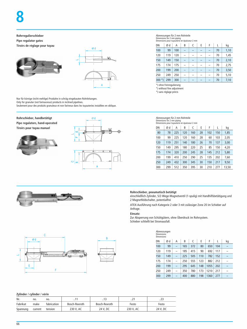
66
100 99 100 – – – – 70 1,10
120 119 120 – – – – 70 1,45
150 149 150 – – – – 70 2,10
175 174 175 – – – – 70 2,75
200 199 200 – – – – 70 3,50
250 249 250 – – – – 70 5,10
300 *) 299 300 – – – – 70 7,10
Abmessungen für 2 mm RohrteileDimensions for 2 mm pipingDimensions pour tuyauterie en épaisseur 2 mm
DN Ø d A B C E F L kg
Abmessungen für 2 mm RohrteileDimensions for 2 mm pipingDimensions pour tuyauterie en épaisseur 2 mm
DN Ø d A B C E F L kg
100 99 – 165 372 80 650 104 –
120 119 – 185 415 90 692 117 –
150 149 – 225 505 110 782 152 –
175 174 – 250 555 123 882 212 –
200 199 – 295 645 148 1055 202 –
250 249 – 350 780 173 1210 217 –
300 299 – 400 880 198 1360 277 –
AbmessungenDimensionsDimensions
DN Ø d A B C E F L kg
d
L
A
Rohrregulierschieber
Pipe regulator gates
Tiroirs de réglage pour tuyau
8
d
L
C
E
B
F
d
L
A
EF
BC
Rohrschieber, handbetätigt
Pipe regulators, hand-operated
Tiroirs pour tuyau manuel
Rohrschieber, pneumatisch betätigteinschließlich Zylinder, 5/2-Wege-Magnetventil (1-spulig) mit Handhilfsbetätigung und2 Magnetfeldschalter, potentialfrei
ATEX-Ausführung nach Kategorie 2 oder 3 mit zulässiger Zone 20 im Schieber aufAnfrage.
Einsatz:Zur Absperrung von Schüttgütern, ohne Überdruck im Rohrsystem.Schieber schließt bei Stromausfall.
Nur für körnige (nicht mehlige) Produkte in schräg eingebauten Rohrleitungen.Only for granular (not farinaceous) products in inclined pipelines.Seulement pour des produits granuleux et non farineux dans les tuyauteries installées en oblique.
80 78 225 120 160 28 102 150 1,85
100 99 225 120 160 28 60 103 2,05
120 119 251 140 180 26 70 137 3,00
150 149 295 180 220 25 85 150 4,20
175 174 320 200 245 28 145 212 5,80
200 199 410 250 290 25 135 202 7,60
250 249 432 300 345 30 150 217 9,50
300 299 512 350 395 30 210 277 13,50
*) ohne Feinregulierung*) without fine adjustment*) sans réglage précis
Zylinder / cylinder / vérin
Nr. no. no. ..11 ..13 ..21 ..23
Fabrikat make fabrication Bosch-Rexroth Bosch-Rexroth Festo Festo
Spannung current tension 230 V, AC 24 V, DC 230 V, AC 24 V, DC
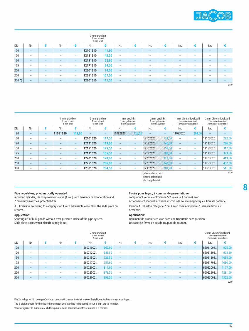
67
2 mm grundiert2 mm primed2 mm peint
1 mm grundiert 2 mm grundiert 1 mm verzinkt 2 mm verzinkt 1 mm Chromnickelstahl 2 mm Chromnickelstahl1 mm primed 2 mm primed 1 mm galvanized 2 mm galvanized 1 mm stainless steel 2 mm stainless steel1 mm peint 2 mm peint 1 mm galvanisé 2 mm galvanisé 1 mm acier inoxydable 2 mm acier inoxydable
– –
– –
– –
– –
– –
– –
– –
– –
– –
– –
– –
– –
– –
– –
12101610 41,60
12121610 43,20
12151610 52,60
12171610 64,00
12201610 74,00
12251610 107,00
12301610 111,50
– –
– –
– –
– –
– –
– –
– –
– –
– –
– –
– –
– –
– –
– –
– –
– –
– –
– –
– –
– –
– –
– –
– –
– –
– –
– –
– –
– –
Nr. € Nr. € Nr. € Nr. € Nr. € Nr. € Nr. €
Nr. € Nr. € Nr. € Nr. € Nr. € Nr. € Nr. €
DN
DN
2110
100
120
150
175
200
250
300 *)
2 mm grundiert 2 mm Chromnickelstahl2 mm primed 2 mm stainless steel2 mm peint 2 mm acier inoxydable
– –
– –
– –
– –
– –
– –
– –
– –
– –
– –
– –
– –
– –
– –
56021002.. 662,00
56021202.. 686,50
56021502.. 726,50
56021702.. 757,00
56022002.. 817,00
56022502.. 879,50
56023002.. 959,50
– –
– –
– –
– –
– –
– –
– –
– –
– –
– –
– –
– –
– –
– –
– –
– –
– –
– –
– –
– –
– –
66021002.. 925,00
66021202.. 975,50
66021502.. 1035,00
66021702.. 1090,00
66022002.. 1177,00
66022502.. 1281,00
66023002.. 1352,00
Nr. € Nr. € Nr. € Nr. € Nr. € Nr. € Nr. €DN
2290
100
120
150
175
200
250
300
8Pipe regulators, pneumatically operatedincluding cylinder, 5/2-way-solenoid-valve (1 coil) with auxiliary hand operation and 2 proximity-switches, potential-free
ATEX version according to category 2 or 3 with admissible Zone 20 in the slide plate onrequest.
Application:Shutting off of bulk goods without over-pressure inside of the pipe system.Slide plate closes when electric supply is cut.
Tiroirs pour tuyau, à commande pneumatiquecomprenant vérin, électrovanne 5/2 voies (à 1 bobine) avec actionnement manuel auxiliaire et 2 fins de course magnétiques, libre de potentiel
Version ATEX selon catégorie 2 ou 3 avec zone admissible 20 dans le tiroir surdemande.
Application:Isolement de produits en vrac dans une tuyauterie sans pression.Le clapet se ferme en cas de coupure de courant.
2120
– –
– –
– –
– –
– –
– –
– –
– –
11081620 113,00
– –
– –
– –
– –
– –
– –
– –
– –
12101620 117,50
12121620 119,00
12151620 125,50
12171620 155,50
12201620 170,00
12251620 206,00
12301620 234,50
11083620 264,00
– –
– –
– –
– –
– –
– –
– –
– –
12103620 282,00
12123620 286,00
12153620 317,00
12173620 373,50
12203620 413,50
12253620 457,00
12303620 511,00
80
100
120
150
175
200
250
300
galvanisch verzinktelectro galvanizedelectro galvanisé
Die 2-stellige Nr. für den gewünschten pneumatischen Antrieb ist unserer 8-stelligen Artikelnummer anzufügen.
The 2-digit number for the desired pneumatic actuator has to be added to our 8-digit article number.
Veuillez ajouter le numéro à 2 chiffres pour le vérin souhaité à notre référence à 8 chiffres.
11082620 125,50
– –
– –
– –
– –
– –
– –
– –
– –
12102620 132,50
12122620 140,50
12152620 159,50
12172620 189,50
12202620 212,00
12252620 242,00
12302620 281,00
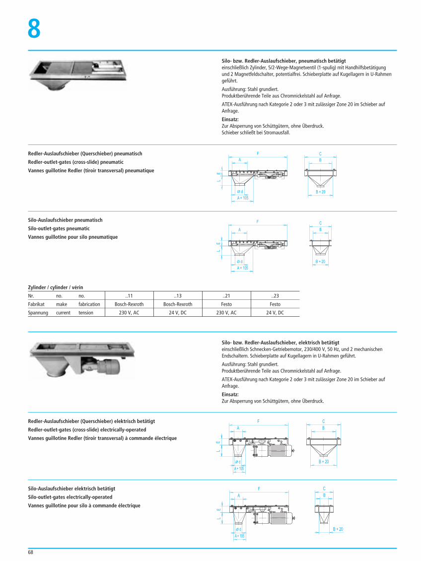
68
8
LE
A
d
A + 105
F
B + 20
C
B
A
L
d
A + 105
EF
B + 20
C
B
Silo- bzw. Redler-Auslaufschieber, pneumatisch betätigteinschließlich Zylinder, 5/2-Wege-Magnetventil (1-spulig) mit Handhilfsbetätigung und 2 Magnetfeldschalter, potentialfrei. Schieberplatte auf Kugellagern in U-Rahmengeführt.
Ausführung: Stahl grundiert.Produktberührende Teile aus Chromnickelstahl auf Anfrage.
ATEX-Ausführung nach Kategorie 2 oder 3 mit zulässiger Zone 20 im Schieber aufAnfrage.
Einsatz:Zur Absperrung von Schüttgütern, ohne Überdruck.Schieber schließt bei Stromausfall.
Redler-Auslaufschieber (Querschieber) pneumatisch
Redler-outlet-gates (cross-slide) pneumatic
Vannes guillotine Redler (tiroir transversal) pneumatique
Silo-Auslaufschieber pneumatisch
Silo-outlet-gates pneumatic
Vannes guillotine pour silo pneumatique
A
L
d
A + 105
E
F
B + 20
C
B
B + 20
C
BA
L
d
A + 105
E
F
Silo- bzw. Redler-Auslaufschieber, elektrisch betätigteinschließlich Schnecken-Getriebemotor, 230/400 V, 50 Hz, und 2 mechanischenEndschaltern. Schieberplatte auf Kugellagern in U-Rahmen geführt.
Ausführung: Stahl grundiert.Produktberührende Teile aus Chromnickelstahl auf Anfrage.
ATEX-Ausführung nach Kategorie 2 oder 3 mit zulässiger Zone 20 im Schieber aufAnfrage.
Einsatz:Zur Absperrung von Schüttgütern, ohne Überdruck.
Redler-Auslaufschieber (Querschieber) elektrisch betätigt
Redler-outlet-gates (cross-slide) electrically-operated
Vannes guillotine Redler (tiroir transversal) à commande électrique
Silo-Auslaufschieber elektrisch betätigt
Silo-outlet-gates electrically-operated
Vannes guillotine pour silo à commande électrique
Zylinder / cylinder / vérin
Nr. no. no. ..11 ..13 ..21 ..23
Fabrikat make fabrication Bosch-Rexroth Bosch-Rexroth Festo Festo
Spannung current tension 230 V, AC 24 V, DC 230 V, AC 24 V, DC
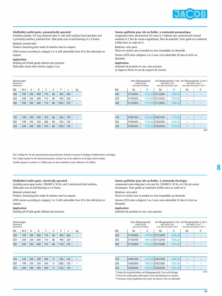
69
8
Silo(Redler)-outlet-gates, pneumatically operatedincluding cylinder, 5/2-way-solenoid-valve (1 coil) with auxiliary hand operation and2 proximity-switches, potential-free. Slide plate runs on ball bearings in a U-frame.
Material: primed steel. Product-contacting parts made of stainless steel on request.
ATEX version according to category 2 or 3 with admissible Zone 20 in the slide plate onrequest.
Application:Shutting off of bulk goods without over-pressure.Slide plate closes when electric supply is cut.
Vannes guillotine pour silo ou Redler, à commande pneumatique, comprenant vérin, électrovanne 5/2 voies (à 1 bobine) avec actionnement manuelauxiliaire et 2 fins de course magnétiques, libre de potentiel. Tiroir guidé sur roulementà billes dans un cadre en U.
Matériau: acier peint.Pièces en contact avec le produit en acier inoxydable sur demande.
Version ATEX selon catégorie 2 ou 3 avec zone admissible 20 dans le tiroir surdemande.
Application:Isolement de produits en vrac, sans pression.Le clapet se ferme en cas de coupure de courant.
ohne Übergangsstückwithout spout
sans pièce de liaison
mit Übergangsstück 2 mmwith spout 2 mm
avec pièce de liaison 2mm
mit Übergangsstück 3 mm*)with spout 3 mm*)
avec pièce de liaison 3 mm*)
57102001.. 1122,00
57102501.. 1153,00
57103001.. 1197,00
57122001.. 1296,00
57122501.. 1333,00
57123001.. 1386,00
– –
– –
– –
Nr. € Nr. € Nr. €DN
200
250
300
200 199 200 600 710 86 852 360 –
250 249 250 600 710 86 952 320 –
300 299 300 600 710 86 1052 270 –
AbmessungenDimensionsDimensions
DN Ø d A B C E F L kg
57601501.. 1054,00
57602001.. 1076,00
57602501.. 1132,00
57621501.. 1173,00
57622001.. 1216,00
57622501.. 1270,00
– –
– –
– –2300
150
200
250
ohne Übergangsstückwithout spout
sans pièce de liaison
mit Übergangsstück 2 mmwith spout 2 mm
avec pièce de liaison 2mm
mit Übergangsstück 3 mm*)with spout 3 mm*)
avec pièce de liaison 3 mm*)
57102005 1479,00
57102505 1491,00
57103005 1502,00
57122005 1636,00
57122505 1655,00
57123005 1691,00
– –
– –
– –
Nr. € Nr. € Nr. €DN
200
250
300
57601505 1375,00
57602005 1402,00
57602505 1444,00
57621505 1494,00
57622005 1531,00
57622505 1581,00
– –
– –
– –2310
150
200
250
150 149 200 200 310 86 852 150 –
200 199 250 250 360 86 952 150 –
250 249 300 300 410 86 1052 150 –
Silo(Redler)-outlet-gates, electrically operatedincluding worm-gear-motor, 230/400 V, 50 Hz, and 2 mechanical limit-switches. Slide plate runs on ball bearings in a U-frame.
Material: primed steel.Product-contacting parts made of stainless steel on request.
ATEX version according to category 2 or 3 with admissible Zone 20 in the slide plate onrequest.
Application:Shutting off of bulk goods without over-pressure.
Vannes guillotine pour silo ou Redler, à commande électriquecomprenant moto réducteur à vis sans fin, 230/400 V, 50 Hz, et 2 fins de coursemécaniques. Tiroir guidé sur roulement à billes dans un cadre en U.
Matériau: acier peint.Pièces en contact avec le produit en acier inoxydable sur demande.
Version ATEX selon catégorie 2 ou 3 avec zone admissible 20 dans le tiroir surdemande.
Application:Isolement de produits en vrac, sans pression.
200 199 200 600 710 86 845 360 –
250 249 250 600 710 86 995 320 –
300 299 300 600 710 86 1145 270 –
AbmessungenDimensionsDimensions
DN Ø d A B C E F L kg
150 149 200 200 304 71 932 150 –
200 199 250 250 354 71 1082 150 –
250 249 300 300 404 71 1232 150 –
*) Preise für Auslaufschieber mit Übergangsstück 3 mm auf Anfrage.*) Prices for outlet-gates with spout 3 mm wall-thickness on request.*) Prix pour vannes guillotine avec pièce de liaison 3 mm sur demande.
Die 2-stellige Nr. für den gewünschten pneumatischen Antrieb ist unserer 8-stelligen Artikelnummer anzufügen.
The 2-digit number for the desired pneumatic actuator has to be added to our 8-digit article number.
Veuillez ajouter le numéro à 2 chiffres pour le vérin souhaité à notre référence à 8 chiffres.

70
Übersicht 2-Wege-KlappenEinsatzkriterien9Alle 2-Wege-Klappen,Klappkästen mit Kragen, Klappkästen mit Dichtung,2-Wege-Verteiler 60° und 2-Wege-Verteiler 45°,sind sowohl in symmetrischer wie auch in asymmetrischer Bauform erhältlich.Symmetrische Ausführungen sind optimiert für den Einbau in senkrecht verlaufendenSchüttgutleitungen, asymmetrische für Leitungen, die unter einer Neigung verlaufen,die dem Winkel zwischen den Ausläufen entspricht. Bei den unteren Bildern wurde nur die symmetrische Form dargestellt.
Alle Ausführungen der 2-Wege-Klappen können angeschweißte Flansche mitAbmessungen nach Kundenwunsch erhalten. Dabei sind Ausläufe ggf. auch Einläufeverlängert ausgeführt.Um den Innendurchmesser der anschließenden Rohre zu erreichen, können dieVerlängerungen auch konisch ausgeführt werden.
Klappkästen mit KragenDie Abdichtung des angewählten Weges wird durch eine Überdeckung des Einlauf-kragens zur Innenklappe und einer Überdeckung der U-förmigen Innenklappe zumweiterführenden Rohr erreicht.Für abrasive Produkte können Einlauf und Innenklappe mit Verschleißgummi oderPolyurethan ausgekleidet geliefert werden.3 mm starke Ausführungen sind bis Ø 300 mm nach außen explosionsdruckstoßfest bis3 bar Überdruck zertifiziert. Die Einbaumaße sind identisch mit den unten aufgeführtenKlappkästen mit Dichtung.Einsatz:Gravitative Förderung frei – ohne Rückstau – fließender, nicht haftender, körnigerSchüttgüter. Bei pulverförmigen Produkten muss – besonders bei Überduck im freienoder Unterdruck im geschlossenen Auslauf – mit Undichtheiten zum abgesperrtenAuslauf gerechnet werden.Für den Einsatz in lufttechnischen Anlagen aufgrund fehlender Abdichtung derInnenklappe nicht einsetzbar.Ausführung, Abmessung und Preise Seite 72 - 75.
Klappkästen mit Dichtung2-lagige, gerade Innenklappe mit zwischenliegender Dichtung aus NBR, helle Lebensmittelqualität, temperaturbeständig bis 80 °C.Die Einbaumaße sind identisch mit den oben aufgeführten Klappkästen mit Kragen.Einsatz:Gravitative Förderung frei fließender Schüttgüter sowie in lufttechnischen Anlagen beiDifferenzdrücken bis 0,1 bar. Achtung: Die Antriebe sind nicht für die Belastung aufgrund vorgenannter Differenz-drücke ausgelegt. Stärkere Antriebe auf Anfrage.Unterhalb der Welle ist keine Dichtung angebracht, so dass bei höheren Anforderungenan die Dichtheit zum geschlossenen Abgang der 2-Wege-Verteiler verwendet werdensollte.Ausführung, Abmessung und Preise Seite 76 -79.
2-Wege-Verteiler 60°-Form, alternativ 45°-Form2-lagige, gerade Innenklappe mit zwischenliegender Dichtung aus Silikon, helleQualität, bei trocknen Medien temperaturbeständig bis 180 °C.Zur Anpressung der Dichtung ist das Gehäuse im Bereich der Klappenendstellungenverjüngt ausgebildet. Unterhalb der Welle befindet sich eine von außen nachstellbareDichtung aus Silikon. Wellen kugelgelagert mit Flach-Ring-Dichtung aus Silikon.Die komplette Innenklappe einschließlich aller Dichtungen ist auswechselbar, ohne denVerteiler aus dem Rohrsystem zu entfernen.Einsatz:Gravitative Förderung frei fließender Schüttgüter sowie in lufttechnischen Anlagen beiDifferenzdrücken bis 0,3 bar.Achtung: Die Antriebe sind nicht für die Belastung aufgrund vorgenannter Differenz-drücke ausgelegt. Stärkere Antriebe auf Anfrage.Die 45°-Ausführung ist besser geeignet für die Umlenkung empfindlicherer undschlechter fließender Förderprodukte.Ausführung, Abmessung und Preise Seite 80 - 87.
symmetrical version asymmetrical version
71
Overview of two-way-valvesSummary of applications
Vue d’ensemble clapet 2 voiesCritères d’utilisation
9
All two-way-valves,two-way-valves with inlet collar, two-way-valves with seal, two-way distributors 60° and two-way distributors 45°,are available in symmetric as well as in asymmetric form.Symmetrical versions are optimized for an installation in vertical bulk goods lines,asymmetric ones for lines that have an inclination that corresponds to the anglebetween the outlets.The pictures below only show the symmetric form.
Toutes les boîtes 2 voies,boîtes à clapet avec collet, boîtes à clapet avec joint,distributeurs 2 voies à 60° et distributeurs 2 voies à 45°,sont disponibles autant sous forme symétrique qu'asymétrique.Les versions symétriques sont optimisés pour être montés dans des conduits verticauxà vrac, les asymétriques pour les conduits avec une inclinaison correspondant à l'angleentre les sorties.Les illustrations ci-dessus ne montrent que la forme symétrique.
All versions of two-way-valves can be supplied with welded-on flanges specially tocustomers’ specifications on request. There the outlets and, if necessary, the inlets areextended.To get the inside diameter of the following pipes, the elongations may be conical.
Two-way-valves with inlet collarThe sealing of the selected path is reached by a cover of the inlet lip to the inside valveand a cover of the U-shaped inside valve to the next following pipe.For abrasive products the inlet and the inside valve can be delivered with a lining ofrubber or polyurethane.3 mm thick versions are certified as shock-explosion proof up to a Ø 300 mm to theoutside up to 3 bar overpressure. Dimensions same as two-way-valves with seal (see below).Application:For gravity conveying of free-flowing – without backlog –, non-glutinous, granular bulkgoods. With powdery products, – especially with a over-pressure in the free orunderpressure in the closed outlet – there could be leakages in the closed outlet.An application in ventilation plants is not recommended due to the absence of a flapseal.Version, dimensions and prices, see page 72 - 75.
Two-way-valves with seal2-layer, straight flap with intermediate seal of NBR,light food quality, temperature resistant to 80 °C.Dimensions same as two-way-valves with inlet collar (see above).Application:For gravity conveying of free-flowing bulk goods and ventilation plants with differentialpressure up to 0.1 bar. Attention: The actuators are not constructed for forces caused by above mentioneddifferential pressures. More powerful actuators on request.Below the shaft there is no seal, so that for higher requirements with regard totightness towards the closed outlet the two-way distributor should be used.Version, dimensions and prices, see page 76 - 79.
Two-way-distributors 60°, alternative 45°2-layer, straight flap with intermediate seal of Silicone, light quality, for dry materialstemperature resistant up to 180 °C.To press on the seal, the housing reduces in the area of the valve end position. Belowthe shaft there is a seal of Silicone that can be re-adjusted from outside. Shafts withball-bearing and flat ring-seal of Silicone.The complete inside valve including all seals can be exchanged without removing thedistributor from the pipe system.Application:For gravity conveying of free-flowing bulk goods and ventilation plants with differentialpressure up to 0.3 bar.Attention: The actuators are not constructed for forces caused by above mentioneddifferential pressures. More powerful actuators on request.The 45° version is better suitable for a deflection of more sensitive products andproducts with bad flow properties.Version, dimensions and prices, see page 80 - 87.
Toutes les versions des clapets à 2 voies peuvent être munies de brides soudées selonles souhaits du client. Les sorties, dans certains cas les entrées également, sont sousforme rallongée. Afin de pouvoir obtenir le diamètre intérieur de tuyaux qui continuent, les rallongespeuvent se présenter également sous forme conique.
Boîtes à clapet avec colletL'étanchéité de la voie sélectionnée est obtenue par un chevauchement de la colleretted'entrée vers le clapet intérieur et un chevauchement du clapet en forme de U vers letuyau qui continue.L'entrée et le clapet intérieur peuvent être fournis revêtus de caoutchouc d'usure ou depolyuréthane. Les versions de 3 mm d'épaisseur jusqu'à un Ø 300 mm vers l'extérieur sont certifiérésistantes à la surpression jusqu'à 3 bar. Les dimensions d'installation sont identiquesà ceux des boîtes à clapet avec joint ci-dessous.Utilisation:Ecoulement gravitaire de produits granuleux, libre – sans refoulement – produitscoulant en vrac, non collants. En cas de produits pulvérulents – surtout en cas desurpression dans la sortie levée ou de sous-pression dans la sortie fermée – il fauts’attendre à des problèmes d’étanchéité vers la sortie bloquée.En raison du manque d'étanchéité du clapet intérieur, ces boîtes ne conviennent querarement pour des applications dans des installations aérauliques.Version, dimensions et prix, voir page 72 - 75.
Boîtes à clapet avec jointClapet droit intérieur à 2 couches avec joint intermédiaire en NBR, qualité alimentaireclaire, résistance aux températures jusqu'à 80 °C. Les dimensions d'installation sontidentiques à ceux des boîtes à clapet avec collet ci-dessus.Utilisation:Ecoulement gravitaire de produits à écoulement facile ainsi que pour des installationsaérauliques lors de pressions différentielles jusqu'à 0,1 bar. Attention: Les entraînements ne sont pas conçus pour la charge en raison des pressionsdifférentielles précitées. Entraînements plus puissants sur demande.Aucun joint n'est installé en dessous de l'arbre, de sorte que pour des sollicitationsfortes en termes d'étanchéité il est conseillé d'utiliser le distributeur à 2 voies pour lasortie fermée.Version, dimensions et prix, voir page 76 - 79.
Distributeurs 2 voies 60° ou 45°Clapet droit intérieur à 2 couches avec joint intermédiaire en silicone, qualité claire,résistance au température si médias secs jusqu'à 180 °C.Le carter se rajeunit dans la zone des positions finale du clapet pour permettre d'ypresser le joint. En dessous de l'arbre se trouve un joint en silicone réglable parl'extérieur. Arbres soutenus par roulements à billes avec joint annulaire plat ensilicone. Le clapet intérieur complet y compris tous les joints peut se remplacer sans devoir sortirle distributeur du système de tuyauterie.Utilisation:Ecoulement gravitaire de produits à écoulement facile ainsi que pour des installationsaérauliques lors de pressions différentielles jusqu'à 0,3 bar. Attention: Les entraînements ne sont pas conçus pour la charge en raison des pressionsdifférentielles précitées. Entraînements plus puissants sur demande.La version à 45° convient mieux pour la déviation de produits à convoyer plus fragileset qui coulent moins bien.Version, dimensions et prix, voir page 80 - 87.
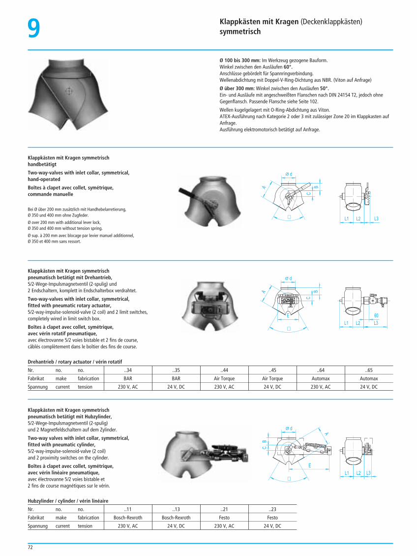
72
Klappkästen mit Kragen (Deckenklappkästen)symmetrisch9Ø 100 bis 300 mm: Im Werkzeug gezogene Bauform.Winkel zwischen den Ausläufen 60°.Anschlüsse gebördelt für Spannringverbindung.Wellenabdichtung mit Doppel-V-Ring-Dichtung aus NBR. (Viton auf Anfrage)
Ø über 300 mm: Winkel zwischen den Ausläufen 50°.Ein- und Ausläufe mit angeschweißten Flanschen nach DIN 24154 T2, jedoch ohneGegenflansch. Passende Flansche siehe Seite 102.
Wellen kugelgelagert mit O-Ring-Abdichtung aus Viton.ATEX-Ausführung nach Kategorie 2 oder 3 mit zulässiger Zone 20 im Klappkasten aufAnfrage.Ausführung elektromotorisch betätigt auf Anfrage.
Klappkästen mit Kragen symmetrischhandbetätigt
Two-way-valves with inlet collar, symmetrical,hand-operated
Boîtes à clapet avec collet, symétrique,commande manuelle
Bei Ø über 200 mm zusätzlich mit Handhebelarretierung, Ø 350 und 400 mm ohne Zugfeder.
Ø over 200 mm with additional lever lock, Ø 350 and 400 mm without tension spring.
Ø sup. à 200 mm avec blocage par levier manuel additionnel,Ø 350 et 400 mm sans ressort.
A
d
L1
B
C
L2 L3¼
Klappkästen mit Kragen symmetrisch pneumatisch betätigt mit Drehantrieb,5/2-Wege-Impulsmagnetventil (2-spulig) und2 Endschaltern, komplett in Endschalterbox verdrahtet.
Two-way-valves with inlet collar, symmetrical,fitted with pneumatic rotary actuator,5/2-way-impulse-solenoid-valve (2 coil) and 2 limit switches,completely wired in limit switch box.
Boîtes à clapet avec collet, symétrique,avec vérin rotatif pneumatique,avec électrovanne 5/2 voies bistable et 2 fins de course,câblés complètement dans le boîtier des fins de course.
60
A
d
L1
B
C
L2 L3
E
¼
B
d
L1
A
L2 L3
E
C
¼
Drehantrieb / rotary actuator / vérin rotatif
Nr. no. no. ..34 ..35 ..44 ..45 ..64 ..65
Fabrikat make fabrication BAR BAR Air Torque Air Torque Automax Automax
Spannung current tension 230 V, AC 24 V, DC 230 V, AC 24 V, DC 230 V, AC 24 V, DC
Klappkästen mit Kragen symmetrisch pneumatisch betätigt mit Hubzylinder,5/2-Wege-Impulsmagnetventil (2-spulig)und 2 Magnetfeldschaltern auf dem Zylinder.
Two-way valves with inlet collar, symmetrical,fitted with pneumatic cylinder, 5/2-way-impulse-solenoid-valve (2 coil)and 2 proximity switches on the cylinder.
Boîtes à clapet avec collet, symétrique,avec vérin linéaire pneumatique,avec électrovanne 5/2 voies bistable et2 fins de course magnétiques sur le vérin.
Hubzylinder / cylinder / vérin linéaire
Nr. no. no. ..11 ..13 ..21 ..23
Fabrikat make fabrication Bosch-Rexroth Bosch-Rexroth Festo Festo
Spannung current tension 230 V, AC 24 V, DC 230 V, AC 24 V, DC
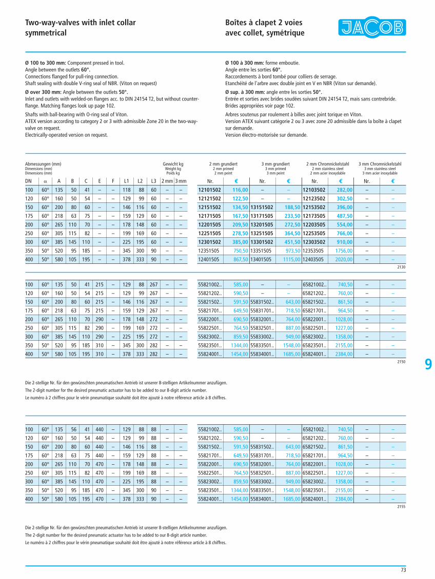
73
Two-way-valves with inlet collarsymmetrical
Boîtes à clapet 2 voies avec collet, symétrique
9
Ø 100 to 300 mm: Component pressed in tool.Angle between the outlets 60°.Connections flanged for pull-ring connection.Shaft sealing with double V-ring seal of NBR. (Viton on request)
Ø over 300 mm: Angle between the outlets 50°.Inlet and outlets with welded-on flanges acc. to DIN 24154 T2, but without counter-flange. Matching flanges look up page 102.
Shafts with ball-bearing with O-ring seal of Viton.ATEX version according to category 2 or 3 with admissible Zone 20 in the two-way-valve on request.Electrically-operated version on request.
Ø 100 à 300 mm: forme emboutie.Angle entre les sorties 60°.Raccordements à bord tombé pour colliers de serrage.Etanchéité de l'arbre avec double joint en V en NBR (Viton sur demande).
Ø sup. à 300 mm: angle entre les sorties 50°.Entrée et sorties avec brides soudées suivant DIN 24154 T2, mais sans contrebride.Brides appropriées voir page 102.
Arbres soutenus par roulement à billes avec joint torique en Viton. Version ATEX suivant catégorie 2 ou 3 avec zone 20 admissible dans la boîte à clapetsur demande.Version électro-motorisée sur demande.
100 60° 135 50 41 – – 118 88 60 – –
120 60° 160 50 54 – – 129 99 60 – –
150 60° 200 80 60 – – 146 116 60 – –
175 60° 218 63 75 – – 159 129 60 – –
200 60° 265 110 70 – – 178 148 60 – –
250 60° 305 115 82 – – 199 169 60 – –
300 60° 385 145 110 – – 225 195 60 – –
350 50° 520 95 185 – – 345 300 90 – –
400 50° 580 105 195 – – 378 333 90 – –
Abmessungen (mm) Gewicht kgDimensions (mm) Weight kgDimensions (mm) Poids kg
DN B A B C E F L1 L2 L3 2 mm 3 mm
2 mm grundiert 3 mm grundiert 2 mm Chromnickelstahl 3 mm Chromnickelstahl2 mm primed 3 mm primed 2 mm stainless steel 3 mm stainless steel2 mm peint 3 mm peint 2 mm acier inoxydable 3 mm acier inoxydable
Nr. € Nr. € Nr. € Nr. €
2130
12101502 116,00
12121502 122,50
12151502 134,50
12171505 167,50
12201505 209,50
12251505 278,50
12301502 385,00
12351505 750,50
12401505 867,50
– –
– –
13151502 188,50
13171505 233,50
13201505 272,50
13251505 364,50
13301502 451,50
13351505 973,50
13401505 1115,00
12103502 282,00
12123502 302,50
12153502 396,00
12173505 487,50
12203505 554,00
12253505 766,00
12303502 910,00
12353505 1756,00
12403505 2020,00
– –
– –
– –
– –
– –
– –
– –
– –
– –
100 60° 135 50 41 215 – 129 88 267 – –
120 60° 160 50 54 215 – 129 99 267 – –
150 60° 200 80 60 215 – 146 116 267 – –
175 60° 218 63 75 215 – 159 129 267 – –
200 60° 265 110 70 290 – 178 148 272 – –
250 60° 305 115 82 290 – 199 169 272 – –
300 60° 385 145 110 290 – 225 195 272 – –
350 50° 520 95 185 310 – 345 300 282 – –
400 50° 580 105 195 310 – 378 333 282 – –2150
55821002.. 585,00
55821202.. 590,50
55821502.. 591,50
55821701.. 649,50
55822001.. 690,50
55822501.. 764,50
55823002.. 859,50
55823501.. 1344,00
55824001.. 1454,00
– –
– –
55831502.. 643,00
55831701.. 718,50
55832001.. 764,00
55832501.. 887,00
55833002.. 949,00
55833501.. 1548,00
55834001.. 1685,00
65821002.. 740,50
65821202.. 760,00
65821502.. 861,50
65821701.. 964,50
65822001.. 1028,00
65822501.. 1227,00
65823002.. 1358,00
65823501.. 2155,00
65824001.. 2384,00
– –
– –
– –
– –
– –
– –
– –
– –
– –
100 60° 135 56 41 440 – 129 88 88 – –
120 60° 160 50 54 440 – 129 99 88 – –
150 60° 200 80 60 440 – 146 116 88 – –
175 60° 218 63 75 440 – 159 129 88 – –
200 60° 265 110 70 470 – 178 148 88 – –
250 60° 305 115 82 470 – 199 169 88 – –
300 60° 385 145 110 470 – 225 195 88 – –
350 50° 520 95 185 470 – 345 300 90 – –
400 50° 580 105 195 470 – 378 333 90 – –2155
55821002.. 585,00
55821202.. 590,50
55821502.. 591,50
55821701.. 649,50
55822001.. 690,50
55822501.. 764,50
55823002.. 859,50
55823501.. 1344,00
55824001.. 1454,00
– –
– –
55831502.. 643,00
55831701.. 718,50
55832001.. 764,00
55832501.. 887,00
55833002.. 949,00
55833501.. 1548,00
55834001.. 1685,00
65821002.. 740,50
65821202.. 760,00
65821502.. 861,50
65821701.. 964,50
65822001.. 1028,00
65822501.. 1227,00
65823002.. 1358,00
65823501.. 2155,00
65824001.. 2384,00
– –
– –
– –
– –
– –
– –
– –
– –
– –
Die 2-stellige Nr. für den gewünschten pneumatischen Antrieb ist unserer 8-stelligen Artikelnummer anzufügen.
The 2-digit number for the desired pneumatic actuator has to be added to our 8-digit article number.
Le numéro à 2 chiffres pour le vérin pneumatique souhaité doit être ajouté à notre référence article à 8 chiffres.
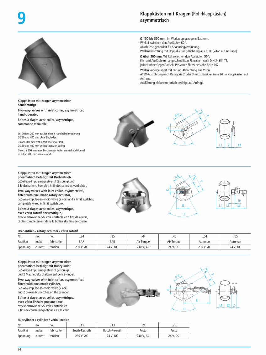
Klappkästen mit Kragen (Rohrklappkästen)asymmetrisch9
74
Ø 100 bis 300 mm: Im Werkzeug gezogene Bauform.Winkel zwischen den Ausläufen 60°.Anschlüsse gebördelt für Spannringverbindung.Wellenabdichtung mit Doppel-V-Ring-Dichtung aus NBR. (Viton auf Anfrage)
Ø über 300 mm: Winkel zwischen den Ausläufen 50°.Ein- und Ausläufe mit angeschweißten Flanschen nach DIN 24154 T2,jedoch ohne Gegenflansch. Passende Flansche siehe Seite 102.
Wellen kugelgelagert mit O-Ring-Abdichtung aus Viton.ATEX-Ausführung nach Kategorie 2 oder 3 mit zulässiger Zone 20 im Klappkasten aufAnfrage.Ausführung elektromotorisch betätigt auf Anfrage.
Klappkästen mit Kragen asymmetrischhandbetätigt
Two-way-valves with inlet collar, asymmetrical,hand-operated
Boîtes à clapet avec collet, asymétrique,commande manuelle
Bei Ø über 200 mm zusätzlich mit Handhebelarretierung, Ø 350 und 400 mm ohne Zugfeder.
Ø over 200 mm with additional lever lock, Ø 350 and 400 mm without tension spring.
Ø sup. à 200 mm avec blocage par levier manuel additionnel,Ø 350 et 400 mm sans ressort.
A
d
L1
B
C
L2 L3
F
¼
Klappkästen mit Kragen asymmetrischpneumatisch betätigt mit Drehantrieb,5/2-Wege-Impulsmagnetventil (2-spulig) und2 Endschaltern, komplett in Endschalterbox verdrahtet.
Two-way valves with inlet collar, asymmetrical,fitted with pneumatic rotary actuator,5/2-way-impulse-solenoid-valve (2 coil) and 2 limit switches,completely wired in limit switch box.
Boîtes à clapet avec collet, asymétrique,avec vérin rotatif pneumatique,avec électrovanne 5/2 voies bistable et 2 fins de course, câblés complètement dans le boîtier des fins de course.
A
d
L1
B
C
L2 L3
F
60
¼
E
A
d
L1
B
C
L2 L3
F
¼
E
Drehantrieb / rotary actuator / vérin rotatif
Nr. no. no. ..34 ..35 ..44 ..45 ..64 ..65
Fabrikat make fabrication BAR BAR Air Torque Air Torque Automax Automax
Spannung current tension 230 V, AC 24 V, DC 230 V, AC 24 V, DC 230 V, AC 24 V, DC
Klappkästen mit Kragen asymmetrischpneumatisch betätigt mit Hubzylinder,5/2-Wege-Impulsmagnetventil (2-spulig)und 2 Magnetfeldschaltern auf dem Zylinder.
Two-way-valves with inlet collar, asymmetrical,fitted with pneumatic cylinder, 5/2-way-impulse-solenoid-valve (2 coil)and 2 proximity switches on the cylinder.
Boîtes à clapet avec collet, asymétrique,avec vérin linéaire pneumatique,avec électrovanne 5/2 voies bistable et2 fins de course magnétiques sur le vérin.
Hubzylinder / cylinder / vérin linéaire
Nr. no. no. ..11 ..13 ..21 ..23
Fabrikat make fabrication Bosch-Rexroth Bosch-Rexroth Festo Festo
Spannung current tension 230 V, AC 24 V, DC 230 V, AC 24 V, DC
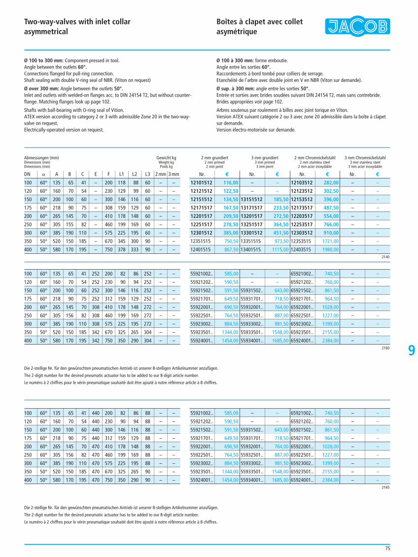
Two-way-valves with inlet collarasymmetrical
Boîtes à clapet avec colletasymétrique
9
75
Ø 100 to 300 mm: Component pressed in tool.Angle between the outlets 60°.Connections flanged for pull-ring connection.Shaft sealing with double V-ring seal of NBR. (Viton on request)
Ø over 300 mm: Angle between the outlets 50°.Inlet and outlets with welded-on flanges acc. to DIN 24154 T2, but without counter-flange. Matching flanges look up page 102.
Shafts with ball-bearing with O-ring seal of Vition.ATEX version according to category 2 or 3 with admissible Zone 20 in the two-way-valve on request.Electrically-operated version on request.
Ø 100 à 300 mm: forme emboutie.Angle entre les sorties 60°.Raccordements à bord tombé pour colliers de serrage.Etanchéité de l'arbre avec double joint en V en NBR (Viton sur demande).
Ø sup. à 300 mm: angle entre les sorties 50°.Entrée et sorties avec brides soudées suivant DIN 24154 T2, mais sans contrebride.Brides appropriées voir page 102.
Arbres soutenus par roulement à billes avec joint torique en Viton.Version ATEX suivant catégorie 2 ou 3 avec zone 20 admissible dans la boîte à clapetsur demande.Version électro-motorisée sur demande.
100 60° 135 65 41 – 200 118 88 60 – –
120 60° 160 70 54 – 230 129 99 60 – –
150 60° 200 100 60 – 300 146 116 60 – –
175 60° 218 90 75 – 308 159 129 60 – –
200 60° 265 145 70 – 410 178 148 60 – –
250 60° 305 155 82 – 460 199 169 60 – –
300 60° 385 190 110 – 575 225 195 60 – –
350 50° 520 150 185 – 670 345 300 90 – –
400 50° 580 170 195 – 750 378 333 90 – –
Abmessungen (mm) Gewicht kgDimensions (mm) Weight kgDimensions (mm) Poids kg
DN B A B C E F L1 L2 L3 2 mm 3 mm
2 mm grundiert 3 mm grundiert 2 mm Chromnickelstahl 3 mm Chromnickelstahl2 mm primed 3 mm primed 2 mm stainless steel 3 mm stainless steel2 mm peint 3 mm peint 2 mm acier inoxydable 3 mm acier inoxydable
Nr. € Nr. € Nr. € Nr. €
2140
12101512 116,00
12121512 122,50
12151512 134,50
12171517 167,50
12201517 209,50
12251517 278,50
12301512 385,00
12351515 750,50
12401515 867,50
– –
– –
13151512 185,50
13171517 233,50
13201517 272,50
13251517 364,50
13301512 451,50
13351515 973,50
13401515 1115,00
12103512 282,00
12123512 302,50
12153512 396,00
12173517 487,50
12203517 554,00
12253517 766,00
12303512 910,00
12353515 1721,00
12403515 1980,00
– –
– –
– –
– –
– –
– –
– –
– –
– –
100 60° 135 65 41 252 200 82 86 252 – –
120 60° 160 70 54 252 230 90 94 252 – –
150 60° 200 100 60 252 300 146 116 252 – –
175 60° 218 90 75 252 312 159 129 252 – –
200 60° 265 145 70 308 410 178 148 272 – –
250 60° 305 156 82 308 460 199 169 272 – –
300 60° 385 190 110 308 575 225 195 272 – –
350 50° 520 150 185 342 670 325 265 304 – –
400 50° 580 170 195 342 750 350 290 304 – –2160
55921002.. 585,00
55921202.. 590,50
55921502.. 591,50
55921701.. 649,50
55922001.. 690,50
55922501.. 764,50
55923002.. 884,50
55923501.. 1344,00
55924001.. 1454,00
– –
– –
55931502.. 643,00
55931701.. 718,50
55932001.. 764,00
55932501.. 887,00
55933002.. 981,50
55933501.. 1548,00
55934001.. 1685,00
65921002.. 740,50
65921202.. 760,00
65921502.. 861,50
65921701.. 964,50
65922001.. 1028,00
65922501.. 1227,00
65923002.. 1399,00
65923501.. 2155,00
65924001.. 2384,00
– –
– –
– –
– –
– –
– –
– –
– –
– –
100 60° 135 65 41 440 200 82 86 88 – –
120 60° 160 70 54 440 230 90 94 88 – –
150 60° 200 100 60 440 300 146 116 88 – –
175 60° 218 90 75 440 312 159 129 88 – –
200 60° 265 145 70 470 410 178 148 88 – –
250 60° 305 156 82 470 460 199 169 88 – –
300 60° 385 190 110 470 575 225 195 88 – –
350 50° 520 150 185 470 670 325 265 90 – –
400 50° 580 170 195 470 750 350 290 90 – –2165
55921002.. 585,00
55921202.. 590,50
55921502.. 591,50
55921701.. 649,50
55922001.. 690,50
55922501.. 764,50
55923002.. 884,50
55923501.. 1344,00
55924001.. 1454,00
– –
– –
55931502.. 643,00
55931701.. 718,50
55932001.. 764,00
55932501.. 887,00
55933002.. 981,50
55933501.. 1548,00
55934001.. 1685,00
65921002.. 740,50
65921202.. 760,00
65921502.. 861,50
65921701.. 964,50
65922001.. 1028,00
65922501.. 1227,00
65923002.. 1399,00
65923501.. 2155,00
65924001.. 2384,00
– –
– –
– –
– –
– –
– –
– –
– –
– –
Die 2-stellige Nr. für den gewünschten pneumatischen Antrieb ist unserer 8-stelligen Artikelnummer anzufügen.
The 2-digit number for the desired pneumatic actuator has to be added to our 8-digit article number.
Le numéro à 2 chiffres pour le vérin pneumatique souhaité doit être ajouté à notre référence article à 8 chiffres.
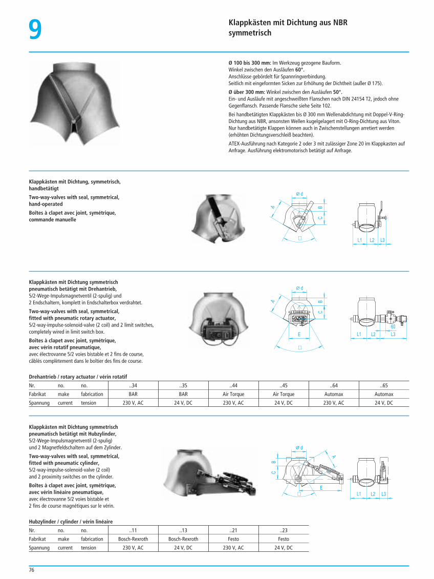
Klappkästen mit Dichtung aus NBRsymmetrisch9
76
Ø 100 bis 300 mm: Im Werkzeug gezogene Bauform.Winkel zwischen den Ausläufen 60°.Anschlüsse gebördelt für Spannringverbindung.Seitlich mit eingeformten Sicken zur Erhöhung der Dichtheit (außer Ø 175).
Ø über 300 mm: Winkel zwischen den Ausläufen 50°.Ein- und Ausläufe mit angeschweißten Flanschen nach DIN 24154 T2, jedoch ohneGegenflansch. Passende Flansche siehe Seite 102.
Bei handbetätigten Klappkästen bis Ø 300 mm Wellenabdichtung mit Doppel-V-Ring-Dichtung aus NBR, ansonsten Wellen kugelgelagert mit O-Ring-Dichtung aus Viton.Nur handbetätigte Klappen können auch in Zwischenstellungen arretiert werden(erhöhten Dichtungsverschleiß beachten).
ATEX-Ausführung nach Kategorie 2 oder 3 mit zulässiger Zone 20 im Klappkasten aufAnfrage. Ausführung elektromotorisch betätigt auf Anfrage.
Klappkästen mit Dichtung, symmetrisch,handbetätigt
Two-way-valves with seal, symmetrical,hand-operated
Boîtes à clapet avec joint, symétrique,commande manuelle
A
d
L1
BC
L2 L3¼
Klappkästen mit Dichtung symmetrischpneumatisch betätigt mit Drehantrieb,5/2-Wege-Impulsmagnetventil (2-spulig) und2 Endschaltern, komplett in Endschalterbox verdrahtet.
Two-way-valves with seal, symmetrical,fitted with pneumatic rotary actuator,5/2-way-impulse-solenoid-valve (2 coil) and 2 limit switches,completely wired in limit switch box.
Boîtes à clapet avec joint, symétrique,avec vérin rotatif pneumatique,avec électrovanne 5/2 voies bistable et 2 fins de course, câblés complètement dans le boîtier des fins de course.
A
d
L1
BC
L2 L3E
60
¼
A
d
L1
BC
L2 L3
E
¼
Drehantrieb / rotary actuator / vérin rotatif
Nr. no. no. ..34 ..35 ..44 ..45 ..64 ..65
Fabrikat make fabrication BAR BAR Air Torque Air Torque Automax Automax
Spannung current tension 230 V, AC 24 V, DC 230 V, AC 24 V, DC 230 V, AC 24 V, DC
Klappkästen mit Dichtung symmetrisch pneumatisch betätigt mit Hubzylinder,5/2-Wege-Impulsmagnetventil (2-spulig)und 2 Magnetfeldschaltern auf dem Zylinder.
Two-way-valves with seal, symmetrical,fitted with pneumatic cylinder, 5/2-way-impulse-solenoid-valve (2 coil)and 2 proximity switches on the cylinder.
Boîtes à clapet avec joint, symétrique,avec vérin linéaire pneumatique,avec électrovanne 5/2 voies bistable et2 fins de course magnétiques sur le vérin.
Hubzylinder / cylinder / vérin linéaire
Nr. no. no. ..11 ..13 ..21 ..23
Fabrikat make fabrication Bosch-Rexroth Bosch-Rexroth Festo Festo
Spannung current tension 230 V, AC 24 V, DC 230 V, AC 24 V, DC
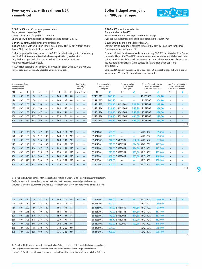
Two-way-valves with seal from NBRsymmetrical
Boîtes à clapet avec joint en NBR, symétrique
9
77
Ø 100 to 300 mm: Component pressed in tool.Angle between the outlets 60°.Connections flanged for pull-ring connection.On the side with formed beads to increase tightness (except Ø 175).
Ø over 300 mm: Angle between the outlets 50°.Inlet and outlets with welded-on flanges acc. to DIN 24154 T2 but without counter-flange. Matching flanges look up page 102.
For hand-operated two-way-valves up to Ø 300 mm shaft sealing with double V-ringseal of NBR, otherwise shafts with ball-bearing with O-ring seal of Viton.Only the hand-operated valves can be locked in intermediate positions (observe increased wear of seals).
ATEX version according to category 2 or 3 with admissible Zone 20 in the two-way-valve on request. Electrically-operated version on request.
Ø 100 à 300 mm: forme emboutie.Angle entre les sorties 60°.Raccordements à bord tombé pour colliers de serrage.Avec dépouilles latérales pour augmenter l’étanchéité (sauf Ø 175).
Ø sup. 300 mm: angle entre les sorties 50°.Entrée et sorties avec brides soudées suivant DIN 24154 T2, mais sans contrebride.Brides appropriées voir page 102.
Pour les boîtes à clapet à commande manuelle jusqu'à Ø 300 mm étanchéité de l'arbrepar un double joint en V en NBR, sinon arbre soutenu par roulement à billes avec jointtorique en Viton. Les boîtes à clapet à commande manuelle peuvent être bloqués dansdes positions intermédiaires (tenir compte de l’usure augmentée des jointsd’étanchéité).
Version ATEX suivant catégorie 2 ou 3 avec zone 20 admissible dans la boîte à clapetsur demande. Version électro-motorisée sur demande.
100 60° 135 50 87 – – 140 88 88 – –
120 60° 160 50 112 – – 148 96 88 – –
150 60° 200 80 136 – – 168 119 88 – –
175 60° 218 63 170 – – 198 147 88 – –
200 60° 265 110 167 – – 199 150 88 – –
250 60° 305 115 215 – – 220 171 88 – –
300 60° 385 145 260 – – 264 213 88 – –
Abmessungen (mm) Gewicht kgDimensions (mm) Weight kgDimensions (mm) Poids kg
DN B A B C E F L1 L2 L3 2 mm 3 mm
2 mm grundiert 3 mm grundiert 2 mm Chromnickelstahl 3 mm Chromnickelstahl2 mm primed 3 mm primed 2 mm stainless steel 3 mm stainless steel2 mm peint 3 mm peint 2 mm acier inoxydable 3 mm acier inoxydable
Nr. € Nr. € Nr. € Nr. €
2170
12101503 262,50
12121503 262,50
12151503 278,00
12171506 324,00
12201506 324,00
12251506 330,00
12301503 404,50
– –
– –
13151503 321,50
13171506 352,50
13201506 352,50
13251506 404,00
13301503 492,00
12103503 404,00
12123503 404,00
12153503 493,00
12173506 666,50
12203506 666,50
12253506 820,50
12303503 956,50
– –
– –
– –
– –
– –
– –
– –
100 60° 135 50 87 193 – 140 110 235 – –
120 60° 160 50 112 193 – 148 118 235 – –
150 60° 200 80 136 193 – 168 138 235 – –
175 60° 218 63 170 193 – 198 168 235 – –
200 60° 265 110 167 225 – 199 169 245 – –
250 60° 305 115 215 225 – 220 190 245 – –
300 60° 385 145 260 225 – 264 234 245 – –
350 50° 520 95 380 310 – 310 265 290 – –
400 50° 580 105 400 335 – 335 290 290 – –2190
55421002.. 699,00
55421202.. 699,00
55421502.. 714,00
55421701.. 779,00
55422001.. 779,00
55422501.. 785,50
55423002.. 858,00
55423501.. 1607,00
55424001.. 1905,00
– –
– –
55431502.. 758,50
55431701.. 814,50
55432001.. 814,50
55432501.. 873,00
55433002.. 952,50
– –
– –
65421002.. 890,50
65421202.. 890,50
65421502.. 979,00
65421701.. 1177,00
65422001.. 1177,00
65422501.. 1329,00
65423002.. 1464,00
65423501.. 2504,00
65424001.. 2901,00
– –
– –
– –
– –
– –
– –
– –
– –
– –
100 60° 135 50 87 440 – 140 110 88 – –
120 60° 160 50 112 440 – 148 118 88 – –
150 60° 200 80 136 440 – 168 138 88 – –
175 60° 218 63 170 440 – 198 168 88 – –
200 60° 265 110 167 470 – 199 169 88 – –
250 60° 305 115 215 470 – 220 190 88 – –
300 60° 385 145 260 470 – 264 234 88 – –
350 50° 520 95 380 470 – 310 265 90 – –
400 50° 580 105 400 470 – 335 290 90 – –2195
55421002.. 699,00
55421202.. 699,00
55421502.. 714,00
55421701.. 779,00
55422001.. 779,00
55422501.. 785,50
55423002.. 858,00
55423501.. 1607,00
55424001.. 1905,00
– –
– –
55431502.. 758,50
55431701.. 814,50
55432001.. 814,50
55432501.. 873,00
55433002.. 952,50
– –
– –
65421002.. 890,50
65421202.. 890,50
65421502.. 979,00
65421701.. 1177,00
65422001.. 1177,00
65422501.. 1329,00
65423002.. 1464,00
65423501.. 2504,00
65424001.. 2901,00
– –
– –
– –
– –
– –
– –
– –
– –
– –
Die 2-stellige Nr. für den gewünschten pneumatischen Antrieb ist unserer 8-stelligen Artikelnummer anzufügen.
The 2-digit number for the desired pneumatic actuator has to be added to our 8-digit article number.
Le numéro à 2 chiffres pour le vérin pneumatique souhaité doit être ajouté à notre référence article à 8 chiffres.
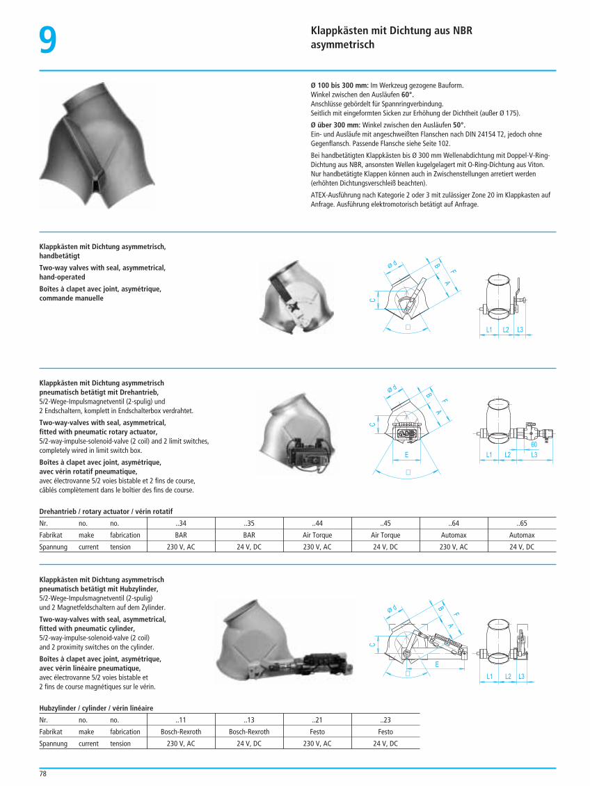
Klappkästen mit Dichtung aus NBRasymmetrisch9
78
Ø 100 bis 300 mm: Im Werkzeug gezogene Bauform.Winkel zwischen den Ausläufen 60°.Anschlüsse gebördelt für Spannringverbindung.Seitlich mit eingeformten Sicken zur Erhöhung der Dichtheit (außer Ø 175).
Ø über 300 mm: Winkel zwischen den Ausläufen 50°.Ein- und Ausläufe mit angeschweißten Flanschen nach DIN 24154 T2, jedoch ohneGegenflansch. Passende Flansche siehe Seite 102.
Bei handbetätigten Klappkästen bis Ø 300 mm Wellenabdichtung mit Doppel-V-Ring-Dichtung aus NBR, ansonsten Wellen kugelgelagert mit O-Ring-Dichtung aus Viton.Nur handbetätigte Klappen können auch in Zwischenstellungen arretiert werden(erhöhten Dichtungsverschleiß beachten).
ATEX-Ausführung nach Kategorie 2 oder 3 mit zulässiger Zone 20 im Klappkasten aufAnfrage. Ausführung elektromotorisch betätigt auf Anfrage.
Klappkästen mit Dichtung asymmetrisch,handbetätigt
Two-way valves with seal, asymmetrical,hand-operated
Boîtes à clapet avec joint, asymétrique,commande manuelle
L2
A
d
L1
F
C
L3
B
¼
Klappkästen mit Dichtung asymmetrischpneumatisch betätigt mit Drehantrieb,5/2-Wege-Impulsmagnetventil (2-spulig) und2 Endschaltern, komplett in Endschalterbox verdrahtet.
Two-way-valves with seal, asymmetrical,fitted with pneumatic rotary actuator,5/2-way-impulse-solenoid-valve (2 coil) and 2 limit switches,completely wired in limit switch box.
Boîtes à clapet avec joint, asymétrique,avec vérin rotatif pneumatique,avec électrovanne 5/2 voies bistable et 2 fins de course, câblés complètement dans le boîtier des fins de course.
A
d
L1
F
C
L3E
B
L2
60
¼
A
d
L1
F
C
L3
B
E
L2¼
Drehantrieb / rotary actuator / vérin rotatif
Nr. no. no. ..34 ..35 ..44 ..45 ..64 ..65
Fabrikat make fabrication BAR BAR Air Torque Air Torque Automax Automax
Spannung current tension 230 V, AC 24 V, DC 230 V, AC 24 V, DC 230 V, AC 24 V, DC
Klappkästen mit Dichtung asymmetrischpneumatisch betätigt mit Hubzylinder,5/2-Wege-Impulsmagnetventil (2-spulig)und 2 Magnetfeldschaltern auf dem Zylinder.
Two-way-valves with seal, asymmetrical,fitted with pneumatic cylinder, 5/2-way-impulse-solenoid-valve (2 coil)and 2 proximity switches on the cylinder.
Boîtes à clapet avec joint, asymétrique,avec vérin linéaire pneumatique,avec électrovanne 5/2 voies bistable et2 fins de course magnétiques sur le vérin.
Hubzylinder / cylinder / vérin linéaire
Nr. no. no. ..11 ..13 ..21 ..23
Fabrikat make fabrication Bosch-Rexroth Bosch-Rexroth Festo Festo
Spannung current tension 230 V, AC 24 V, DC 230 V, AC 24 V, DC
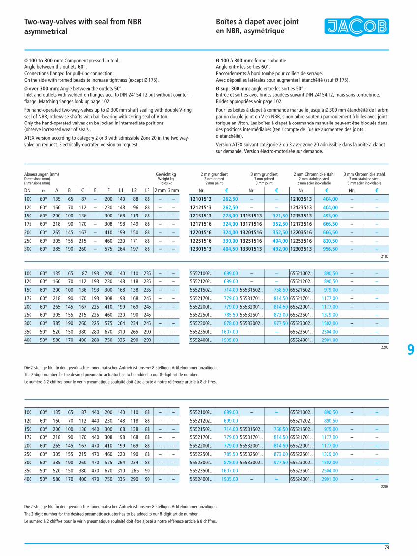
Two-way-valves with seal from NBRasymmetrical
Boîtes à clapet avec joint en NBR, asymétrique
9
79
Ø 100 to 300 mm: Component pressed in tool.Angle between the outlets 60°.Connections flanged for pull-ring connection.On the side with formed beads to increase tightness (except Ø 175).
Ø over 300 mm: Angle between the outlets 50°.Inlet and outlets with welded-on flanges acc. to DIN 24154 T2 but without counter-flange. Matching flanges look up page 102.
For hand-operated two-way-valves up to Ø 300 mm shaft sealing with double V-ringseal of NBR, otherwise shafts with ball-bearing with O-ring seal of Viton.Only the hand-operated valves can be locked in intermediate positions (observe increased wear of seals).
ATEX version according to category 2 or 3 with admissible Zone 20 in the two-way-valve on request. Electrically-operated version on request.
Ø 100 à 300 mm: forme emboutie.Angle entre les sorties 60°.Raccordements à bord tombé pour colliers de serrage.Avec dépouilles latérales pour augmenter l’étanchéité (sauf Ø 175).
Ø sup. 300 mm: angle entre les sorties 50°.Entrée et sorties avec brides soudées suivant DIN 24154 T2, mais sans contrebride.Brides appropriées voir page 102.
Pour les boîtes à clapet à commande manuelle jusqu'à Ø 300 mm étanchéité de l'arbrepar un double joint en V en NBR, sinon arbre soutenu par roulement à billes avec jointtorique en Viton. Les boîtes à clapet à commande manuelle peuvent être bloqués dansdes positions intermédiaires (tenir compte de l’usure augmentée des jointsd’étanchéité).
Version ATEX suivant catégorie 2 ou 3 avec zone 20 admissible dans la boîte à clapetsur demande. Version électro-motorisée sur demande.
100 60° 135 65 87 – 200 140 88 88 – –
120 60° 160 70 112 – 230 148 96 88 – –
150 60° 200 100 136 – 300 168 119 88 – –
175 60° 218 90 170 – 308 198 149 88 – –
200 60° 265 145 167 – 410 199 150 88 – –
250 60° 305 155 215 – 460 220 171 88 – –
300 60° 385 190 260 – 575 264 197 88 – –
Abmessungen (mm) Gewicht kgDimensions (mm) Weight kgDimensions (mm) Poids kg
DN B A B C E F L1 L2 L3 2 mm 3 mm
2 mm grundiert 3 mm grundiert 2 mm Chromnickelstahl 3 mm Chromnickelstahl2 mm primed 3 mm primed 2 mm stainless steel 3 mm stainless steel2 mm peint 3 mm peint 2 mm acier inoxydable 3 mm acier inoxydable
Nr. € Nr. € Nr. € Nr. €
2180
12101513 262,50
12121513 262,50
12151513 278,00
12171516 324,00
12201516 324,00
12251516 330,00
12301513 404,50
– –
– –
13151513 321,50
13171516 352,50
13201516 352,50
13251516 404,00
13301513 492,00
12103513 404,00
12123513 404,00
12153513 493,00
12173516 666,50
12203516 666,50
12253516 820,50
12303513 956,50
– –
– –
– –
– –
– –
– –
– –
100 60° 135 65 87 193 200 140 110 235 – –
120 60° 160 70 112 193 230 148 118 235 – –
150 60° 200 100 136 193 300 168 138 235 – –
175 60° 218 90 170 193 308 198 168 245 – –
200 60° 265 145 167 225 410 199 169 245 – –
250 60° 305 155 215 225 460 220 190 245 – –
300 60° 385 190 260 225 575 264 234 245 – –
350 50° 520 150 380 280 670 310 265 290 – –
400 50° 580 170 400 280 750 335 290 290 – –2200
55521002.. 699,00
55521202.. 699,00
55521502.. 714,00
55521701.. 779,00
55522001.. 779,00
55522501.. 785,50
55523002.. 878,00
55523501.. 1607,00
55524001.. 1905,00
– –
– –
55531502.. 758,50
55531701.. 814,50
55532001.. 814,50
55532501.. 873,00
55533002.. 977,50
– –
– –
65521002.. 890,50
65521202.. 890,50
65521502.. 979,00
65521701.. 1177,00
65522001.. 1177,00
65522501.. 1329,00
65523002.. 1502,00
65523501.. 2504,00
65524001.. 2901,00
– –
– –
– –
– –
– –
– –
– –
– –
– –
100 60° 135 65 87 440 200 140 110 88 – –
120 60° 160 70 112 440 230 148 118 88 – –
150 60° 200 100 136 440 300 168 138 88 – –
175 60° 218 90 170 440 308 198 168 88 – –
200 60° 265 145 167 470 410 199 169 88 – –
250 60° 305 155 215 470 460 220 190 88 – –
300 60° 385 190 260 470 575 264 234 88 – –
350 50° 520 150 380 470 670 310 265 90 – –
400 50° 580 170 400 470 750 335 290 90 – –2205
55521002.. 699,00
55521202.. 699,00
55521502.. 714,00
55521701.. 779,00
55522001.. 779,00
55522501.. 785,50
55523002.. 878,00
55523501.. 1607,00
55524001.. 1905,00
– –
– –
55531502.. 758,50
55531701.. 814,50
55532001.. 814,50
55532501.. 873,00
55533002.. 977,50
– –
– –
65521002.. 890,50
65521202.. 890,50
65521502.. 979,00
65521701.. 1177,00
65522001.. 1177,00
65522501.. 1329,00
65523002.. 1502,00
65523501.. 2504,00
65524001.. 2901,00
– –
– –
– –
– –
– –
– –
– –
– –
– –
Die 2-stellige Nr. für den gewünschten pneumatischen Antrieb ist unserer 8-stelligen Artikelnummer anzufügen.
The 2-digit number for the desired pneumatic actuator has to be added to our 8-digit article number.
Le numéro à 2 chiffres pour le vérin pneumatique souhaité doit être ajouté à notre référence article à 8 chiffres.
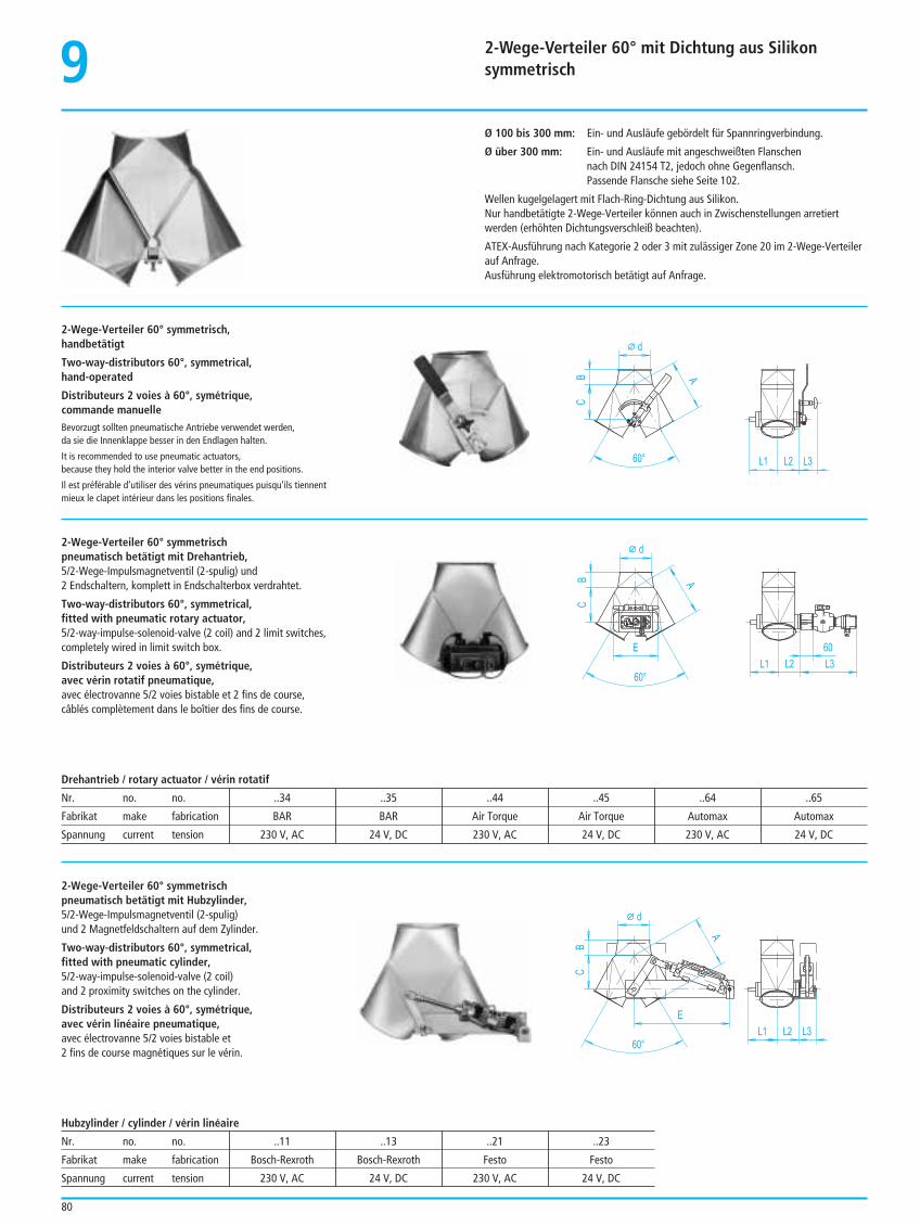
2-Wege-Verteiler 60° mit Dichtung aus Silikonsymmetrisch9
80
Ø 100 bis 300 mm: Ein- und Ausläufe gebördelt für Spannringverbindung.
Ø über 300 mm: Ein- und Ausläufe mit angeschweißten Flanschennach DIN 24154 T2, jedoch ohne Gegenflansch.Passende Flansche siehe Seite 102.
Wellen kugelgelagert mit Flach-Ring-Dichtung aus Silikon.Nur handbetätigte 2-Wege-Verteiler können auch in Zwischenstellungen arretiertwerden (erhöhten Dichtungsverschleiß beachten).
ATEX-Ausführung nach Kategorie 2 oder 3 mit zulässiger Zone 20 im 2-Wege-Verteilerauf Anfrage.Ausführung elektromotorisch betätigt auf Anfrage.
2-Wege-Verteiler 60° symmetrisch,handbetätigt
Two-way-distributors 60°, symmetrical,hand-operated
Distributeurs 2 voies à 60°, symétrique,commande manuelleBevorzugt sollten pneumatische Antriebe verwendet werden,da sie die Innenklappe besser in den Endlagen halten.
It is recommended to use pneumatic actuators, because they hold the interior valve better in the end positions.
Il est préférable d’utiliser des vérins pneumatiques puisqu’ils tiennentmieux le clapet intérieur dans les positions finales.
A
d
L1 L2
C
L360°
B
2-Wege-Verteiler 60° symmetrischpneumatisch betätigt mit Drehantrieb,5/2-Wege-Impulsmagnetventil (2-spulig) und2 Endschaltern, komplett in Endschalterbox verdrahtet.
Two-way-distributors 60°, symmetrical,fitted with pneumatic rotary actuator,5/2-way-impulse-solenoid-valve (2 coil) and 2 limit switches, completely wired in limit switch box.
Distributeurs 2 voies à 60°, symétrique,avec vérin rotatif pneumatique,avec électrovanne 5/2 voies bistable et 2 fins de course, câblés complètement dans le boîtier des fins de course.
A
d
L1 L2
C
L3
60°
B
E 60
A
d
L1 L2
C
L3
60°
B
E
Drehantrieb / rotary actuator / vérin rotatif
Nr. no. no. ..34 ..35 ..44 ..45 ..64 ..65
Fabrikat make fabrication BAR BAR Air Torque Air Torque Automax Automax
Spannung current tension 230 V, AC 24 V, DC 230 V, AC 24 V, DC 230 V, AC 24 V, DC
2-Wege-Verteiler 60° symmetrischpneumatisch betätigt mit Hubzylinder,5/2-Wege-Impulsmagnetventil (2-spulig)und 2 Magnetfeldschaltern auf dem Zylinder.
Two-way-distributors 60°, symmetrical,fitted with pneumatic cylinder, 5/2-way-impulse-solenoid-valve (2 coil)and 2 proximity switches on the cylinder.
Distributeurs 2 voies à 60°, symétrique,avec vérin linéaire pneumatique,avec électrovanne 5/2 voies bistable et2 fins de course magnétiques sur le vérin.
Hubzylinder / cylinder / vérin linéaire
Nr. no. no. ..11 ..13 ..21 ..23
Fabrikat make fabrication Bosch-Rexroth Bosch-Rexroth Festo Festo
Spannung current tension 230 V, AC 24 V, DC 230 V, AC 24 V, DC
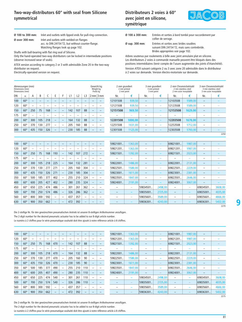
Two-way-distributors 60° with seal from Siliconesymmetrical
Distributeurs 2 voies à 60°avec joint en silicone, symétrique
9
81
Ø 100 to 300 mm: Inlet and outlets with lipped ends for pull-ring connection.
Ø over 300 mm: Inlet and outlets with welded-on flangesacc. to DIN 24154 T2, but without counter-flange.Matching flanges look up page 102.
Shafts with ball-bearing with flat ring seal of Silicone.Only the hand-operated two-way distributors can be locked in intermediate positions(observe increased wear of seals).
ATEX version according to category 2 or 3 with admissible Zone 20 in the two-waydistributor on request.Electrically-operated version on request.
Ø 100 à 300 mm: Entrées et sorties à bord tombé pour raccordement parcollier de serrage.
Ø sup. 300 mm: Entrées et sorties avec brides soudéessuivant DIN 24154 T2, mais sans contrebride.Brides appropriées voir page 102.
Arbres soutenus par roulements à bille avec joint annulaire plat en silicone. Les distributeurs 2 voies à commande manuelle peuvent être bloqués dans despositions intermédiaires (tenir compte de l’usure augmentée des joints d’étanchéité).
Version ATEX suivant catégorie 2 ou 3 avec zone 20 admissible dans le distributeur à 2 voies sur demande. Version électro-motorisée sur demande.
100 60° – – – – – – – – – –
120 60° – – – – – – – – – –
150 60° 250 75 168 – – 142 107 88 – –
175 60° – – – – – – – – – –
200 60° 300 105 218 – – 164 132 88 – –
250 60° 370 130 277 – – 205 160 88 – –
300 60° 435 150 326 – – 230 185 88 – –
Abmessungen (mm) Gewicht kgDimensions (mm) Weight kgDimensions (mm) Poids kg
DN B A B C E F L1 L2 L3 2 mm 3 mm
2 mm grundiert 3 mm grundiert 2 mm Chromnickelstahl 3 mm Chromnickelstahl2 mm primed 3 mm primed 2 mm stainless steel 3 mm stainless steel2 mm peint 3 mm peint 2 mm acier inoxydable 3 mm acier inoxydable
Nr. € Nr. € Nr. € Nr. €
2250
12101508 939,50
12121508 939,50
12151508 969,50
– –
12201508 1000,00
12251508 1031,00
12301508 1125,00
– –
– –
– –
– –
– –
– –
– –
12103508 1589,00
12123508 1589,00
12153508 1629,00
– –
12203508 1678,00
12253508 1712,00
12303508 1793,00
– –
– –
– –
– –
– –
– –
– –
100 60° – – – – – – – – – –
120 60° – – – – – – – – – –
150 60° 250 75 168 193 – 142 107 272 – –
175 60° – – – – – – – – – –
200 60° 300 105 218 225 – 164 132 281 – –
250 60° 370 130 277 271 – 205 160 304 – –
300 60° 435 150 326 271 – 230 185 304 – –
350 60° 500 185 377 402 – 255 210 324 – –
400 60° 600 205 427 402 – 280 235 324 – –
450 60° 650 225 474 486 – 301 261 362 – –
500 60° 700 250 574 486 – 326 286 362 – –
560 60° 800 300 592 – – 437 357 – – –
630 60° 900 350 662 – – 472 392 – – –2270
59821001.. 1363,00
59821201.. 1363,00
59821501.. 1392,00
– –
59822001.. 1486,00
59822501.. 1580,00
59823001.. 1611,00
59823501.. 1847,00
59824001.. 2191,00
– –
– –
– –
– –
– –
– –
– –
– –
– –
– –
– –
– –
– –
59834501.. 2498,00
59835001.. 2725,00
59835601.. 3589,00
59836301.. 4243,00
69821001.. 1987,00
69821201.. 1987,00
69821501.. 2023,00
– –
69822001.. 2131,00
69822501.. 2229,00
69823001.. 2381,00
69823501.. 2646,00
69824001.. 3067,00
– –
– –
– –
– –
– –
– –
– –
– –
– –
– –
– –
– –
– –
69834501.. 3608,00
69835001.. 4035,00
69835601.. 4666,00
69836301.. 5432,00
100 60° – – – – – – – – – –
120 60° – – – – – – – – – –
150 60° 250 75 168 470 – 142 107 88 – –
175 60° – – – – – – – – – –
200 60° 300 105 218 470 – 164 132 88 – –
250 60° 370 130 277 470 – 205 160 90 – –
300 60° 435 150 326 470 – 230 185 90 – –
350 60° 500 185 377 490 – 255 210 110 – –
400 60° 600 205 407 490 – 280 235 110 – –
450 60° 650 225 474 540 – 301 261 110 – –
500 60° 700 250 574 540 – 326 286 110 – –
560 60° 800 300 592 – – 437 357 – – –
630 60° 900 350 662 – – 472 392 – – –2275
59821001.. 1363,00
59821201.. 1363,00
59821501.. 1392,00
– –
59822001.. 1486,00
59822501.. 1580,00
59823001.. 1611,00
59823501.. 1847,00
59824001.. 2191,00
– –
– –
– –
– –
– –
– –
– –
– –
– –
– –
– –
– –
– –
59834501.. 2498,00
59835001.. 2725,00
59835601.. 3589,00
59836301.. 4243,00
69821001.. 1987,00
69821201.. 1987,00
69821501.. 2023,00
– –
69822001.. 2131,00
69822501.. 2229,00
69823001.. 2381,00
69823501.. 2646,00
69824001.. 3067,00
– –
– –
– –
– –
– –
– –
– –
– –
– –
– –
– –
– –
– –
69834501.. 3608,00
69835001.. 4035,00
69835601.. 4666,00
69836301.. 5432,00
Die 2-stellige Nr. für den gewünschten pneumatischen Antrieb ist unserer 8-stelligen Artikelnummer anzufügen.
The 2-digit number for the desired pneumatic actuator has to be added to our 8-digit article number.
Le numéro à 2 chiffres pour le vérin pneumatique souhaité doit être ajouté à notre référence article à 8 chiffres.
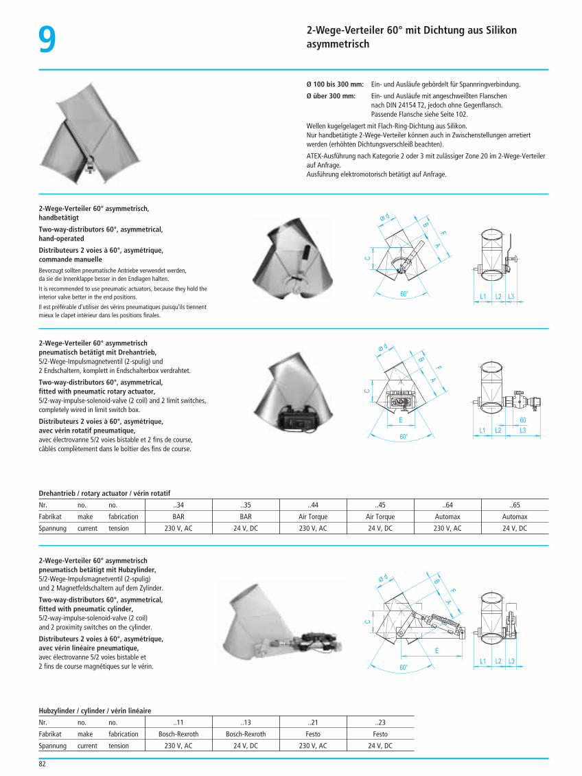
2-Wege-Verteiler 60° mit Dichtung aus Silikonasymmetrisch9
82
Ø 100 bis 300 mm: Ein- und Ausläufe gebördelt für Spannringverbindung.
Ø über 300 mm: Ein- und Ausläufe mit angeschweißten Flanschennach DIN 24154 T2, jedoch ohne Gegenflansch.Passende Flansche siehe Seite 102.
Wellen kugelgelagert mit Flach-Ring-Dichtung aus Silikon.Nur handbetätigte 2-Wege-Verteiler können auch in Zwischenstellungen arretiertwerden (erhöhten Dichtungsverschleiß beachten).
ATEX-Ausführung nach Kategorie 2 oder 3 mit zulässiger Zone 20 im 2-Wege-Verteilerauf Anfrage.Ausführung elektromotorisch betätigt auf Anfrage.
2-Wege-Verteiler 60° asymmetrisch,handbetätigt
Two-way-distributors 60°, asymmetrical,hand-operated
Distributeurs 2 voies à 60°, asymétrique,commande manuelleBevorzugt sollten pneumatische Antriebe verwendet werden,da sie die Innenklappe besser in den Endlagen halten.
It is recommended to use pneumatic actuators, because they hold theinterior valve better in the end positions.
Il est préférable d’utiliser des vérins pneumatiques puisqu’ils tiennentmieux le clapet intérieur dans les positions finales.
A
d
L1 L2
C
L360°
B
F
2-Wege-Verteiler 60° asymmetrischpneumatisch betätigt mit Drehantrieb,5/2-Wege-Impulsmagnetventil (2-spulig) und2 Endschaltern, komplett in Endschalterbox verdrahtet.
Two-way-distributors 60°, asymmetrical,fitted with pneumatic rotary actuator,5/2-way-impulse-solenoid-valve (2 coil) and 2 limit switches,completely wired in limit switch box.
Distributeurs 2 voies à 60°, asymétrique,avec vérin rotatif pneumatique,avec électrovanne 5/2 voies bistable et 2 fins de course, câblés complètement dans le boîtier des fins de course.
A
d
L1 L2
C
L360°
B
F
E 60
A
d
L1 L2
C
L360°
B
F
E
Drehantrieb / rotary actuator / vérin rotatif
Nr. no. no. ..34 ..35 ..44 ..45 ..64 ..65
Fabrikat make fabrication BAR BAR Air Torque Air Torque Automax Automax
Spannung current tension 230 V, AC 24 V, DC 230 V, AC 24 V, DC 230 V, AC 24 V, DC
2-Wege-Verteiler 60° asymmetrischpneumatisch betätigt mit Hubzylinder,5/2-Wege-Impulsmagnetventil (2-spulig)und 2 Magnetfeldschaltern auf dem Zylinder.
Two-way-distributors 60°, asymmetrical,fitted with pneumatic cylinder,5/2-way-impulse-solenoid-valve (2 coil)and 2 proximity switches on the cylinder.
Distributeurs 2 voies à 60°, asymétrique,avec vérin linéaire pneumatique,avec électrovanne 5/2 voies bistable et2 fins de course magnétiques sur le vérin.
Hubzylinder / cylinder / vérin linéaire
Nr. no. no. ..11 ..13 ..21 ..23
Fabrikat make fabrication Bosch-Rexroth Bosch-Rexroth Festo Festo
Spannung current tension 230 V, AC 24 V, DC 230 V, AC 24 V, DC
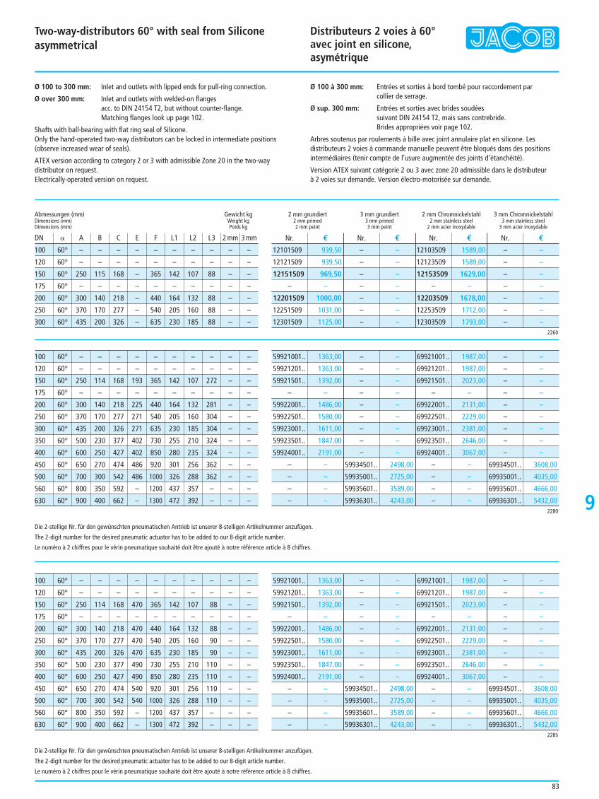
Two-way-distributors 60° with seal from Siliconeasymmetrical
Distributeurs 2 voies à 60°avec joint en silicone, asymétrique
9
83
Ø 100 to 300 mm: Inlet and outlets with lipped ends for pull-ring connection.
Ø over 300 mm: Inlet and outlets with welded-on flangesacc. to DIN 24154 T2, but without counter-flange.Matching flanges look up page 102.
Shafts with ball-bearing with flat ring seal of Silicone.Only the hand-operated two-way distributors can be locked in intermediate positions(observe increased wear of seals).
ATEX version according to category 2 or 3 with admissible Zone 20 in the two-waydistributor on request.Electrically-operated version on request.
Ø 100 à 300 mm: Entrées et sorties à bord tombé pour raccordement parcollier de serrage.
Ø sup. 300 mm: Entrées et sorties avec brides soudéessuivant DIN 24154 T2, mais sans contrebride.Brides appropriées voir page 102.
Arbres soutenus par roulements à bille avec joint annulaire plat en silicone. Lesdistributeurs 2 voies à commande manuelle peuvent être bloqués dans des positionsintermédiaires (tenir compte de l’usure augmentée des joints d’étanchéité).
Version ATEX suivant catégorie 2 ou 3 avec zone 20 admissible dans le distributeur à 2 voies sur demande. Version électro-motorisée sur demande.
100 60° – – – – – – – – – –
120 60° – – – – – – – – – –
150 60° 250 115 168 – 365 142 107 88 – –
175 60° – – – – – – – – – –
200 60° 300 140 218 – 440 164 132 88 – –
250 60° 370 170 277 – 540 205 160 88 – –
300 60° 435 200 326 – 635 230 185 88 – –
Abmessungen (mm) Gewicht kgDimensions (mm) Weight kgDimensions (mm) Poids kg
DN B A B C E F L1 L2 L3 2 mm 3 mm
2 mm grundiert 3 mm grundiert 2 mm Chromnickelstahl 3 mm Chromnickelstahl2 mm primed 3 mm primed 2 mm stainless steel 3 mm stainless steel2 mm peint 3 mm peint 2 mm acier inoxydable 3 mm acier inoxydable
Nr. € Nr. € Nr. € Nr. €
2260
12101509 939,50
12121509 939,50
12151509 969,50
– –
12201509 1000,00
12251509 1031,00
12301509 1125,00
– –
– –
– –
– –
– –
– –
– –
12103509 1589,00
12123509 1589,00
12153509 1629,00
– –
12203509 1678,00
12253509 1712,00
12303509 1793,00
– –
– –
– –
– –
– –
– –
– –
100 60° – – – – – – – – – –
120 60° – – – – – – – – – –
150 60° 250 114 168 193 365 142 107 272 – –
175 60° – – – – – – – – – –
200 60° 300 140 218 225 440 164 132 281 – –
250 60° 370 170 277 271 540 205 160 304 – –
300 60° 435 200 326 271 635 230 185 304 – –
350 60° 500 230 377 402 730 255 210 324 – –
400 60° 600 250 427 402 850 280 235 324 – –
450 60° 650 270 474 486 920 301 256 362 – –
500 60° 700 300 542 486 1000 326 288 362 – –
560 60° 800 350 592 – 1200 437 357 – – –
630 60° 900 400 662 – 1300 472 392 – – –2280
59921001.. 1363,00
59921201.. 1363,00
59921501.. 1392,00
– –
59922001.. 1486,00
59922501.. 1580,00
59923001.. 1611,00
59923501.. 1847,00
59924001.. 2191,00
– –
– –
– –
– –
– –
– –
– –
– –
– –
– –
– –
– –
– –
59934501.. 2498,00
59935001.. 2725,00
59935601.. 3589,00
59936301.. 4243,00
69921001.. 1987,00
69921201.. 1987,00
69921501.. 2023,00
– –
69922001.. 2131,00
69922501.. 2229,00
69923001.. 2381,00
69923501.. 2646,00
69924001.. 3067,00
– –
– –
– –
– –
– –
– –
– –
– –
– –
– –
– –
– –
– –
69934501.. 3608,00
69935001.. 4035,00
69935601.. 4666,00
69936301.. 5432,00
100 60° – – – – – – – – – –
120 60° – – – – – – – – – –
150 60° 250 114 168 470 365 142 107 88 – –
175 60° – – – – – – – – – –
200 60° 300 140 218 470 440 164 132 88 – –
250 60° 370 170 277 470 540 205 160 90 – –
300 60° 435 200 326 470 635 230 185 90 – –
350 60° 500 230 377 490 730 255 210 110 – –
400 60° 600 250 427 490 850 280 235 110 – –
450 60° 650 270 474 540 920 301 256 110 – –
500 60° 700 300 542 540 1000 326 288 110 – –
560 60° 800 350 592 – 1200 437 357 – – –
630 60° 900 400 662 – 1300 472 392 – – –2285
59921001.. 1363,00
59921201.. 1363,00
59921501.. 1392,00
– –
59922001.. 1486,00
59922501.. 1580,00
59923001.. 1611,00
59923501.. 1847,00
59924001.. 2191,00
– –
– –
– –
– –
– –
– –
– –
– –
– –
– –
– –
– –
– –
59934501.. 2498,00
59935001.. 2725,00
59935601.. 3589,00
59936301.. 4243,00
69921001.. 1987,00
69921201.. 1987,00
69921501.. 2023,00
– –
69922001.. 2131,00
69922501.. 2229,00
69923001.. 2381,00
69923501.. 2646,00
69924001.. 3067,00
– –
– –
– –
– –
– –
– –
– –
– –
– –
– –
– –
– –
– –
69934501.. 3608,00
69935001.. 4035,00
69935601.. 4666,00
69936301.. 5432,00
Die 2-stellige Nr. für den gewünschten pneumatischen Antrieb ist unserer 8-stelligen Artikelnummer anzufügen.
The 2-digit number for the desired pneumatic actuator has to be added to our 8-digit article number.
Le numéro à 2 chiffres pour le vérin pneumatique souhaité doit être ajouté à notre référence article à 8 chiffres.
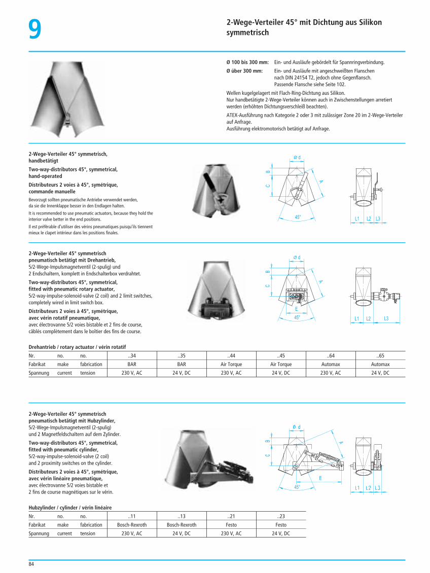
2-Wege-Verteiler 45° mit Dichtung aus Silikonsymmetrisch9
84
Ø 100 bis 300 mm: Ein- und Ausläufe gebördelt für Spannringverbindung.
Ø über 300 mm: Ein- und Ausläufe mit angeschweißten Flanschennach DIN 24154 T2, jedoch ohne Gegenflansch.Passende Flansche siehe Seite 102.
Wellen kugelgelagert mit Flach-Ring-Dichtung aus Silikon.Nur handbetätigte 2-Wege-Verteiler können auch in Zwischenstellungen arretiertwerden (erhöhten Dichtungsverschleiß beachten).
ATEX-Ausführung nach Kategorie 2 oder 3 mit zulässiger Zone 20 im 2-Wege-Verteilerauf Anfrage.Ausführung elektromotorisch betätigt auf Anfrage.
2-Wege-Verteiler 45° symmetrisch,handbetätigt
Two-way-distributors 45°, symmetrical,hand-operated
Distributeurs 2 voies à 45°, symétrique,commande manuelleBevorzugt sollten pneumatische Antriebe verwendet werden,da sie die Innenklappe besser in den Endlagen halten.
It is recommended to use pneumatic actuators, because they hold theinterior valve better in the end positions.
Il est préférable d’utiliser des vérins pneumatiques puisqu’ils tiennentmieux le clapet intérieur dans les positions finales.
A
d
L1 L2
C
L345°
B
2-Wege-Verteiler 45° symmetrischpneumatisch betätigt mit Drehantrieb,5/2-Wege-Impulsmagnetventil (2-spulig) und2 Endschaltern, komplett in Endschalterbox verdrahtet.
Two-way-distributors 45°, symmetrical,fitted with pneumatic rotary actuator,5/2-way-impulse-solenoid-valve (2 coil) and 2 limit switches,completely wired in limit switch box.
Distributeurs 2 voies à 45°, symétrique,avec vérin rotatif pneumatique,avec électrovanne 5/2 voies bistable et 2 fins de course, câblés complètement dans le boîtier des fins de course.
A
d
L1 L2
C
L345°
B
E
E
45°
Drehantrieb / rotary actuator / vérin rotatif
Nr. no. no. ..34 ..35 ..44 ..45 ..64 ..65
Fabrikat make fabrication BAR BAR Air Torque Air Torque Automax Automax
Spannung current tension 230 V, AC 24 V, DC 230 V, AC 24 V, DC 230 V, AC 24 V, DC
2-Wege-Verteiler 45° symmetrischpneumatisch betätigt mit Hubzylinder,5/2-Wege-Impulsmagnetventil (2-spulig)und 2 Magnetfeldschaltern auf dem Zylinder.
Two-way-distributors 45°, symmetrical,fitted with pneumatic cylinder, 5/2-way-impulse-solenoid-valve (2 coil)and 2 proximity switches on the cylinder.
Distributeurs 2 voies à 45°, symétrique,avec vérin linéaire pneumatique,avec électrovanne 5/2 voies bistable et2 fins de course magnétiques sur le vérin.
Hubzylinder / cylinder / vérin linéaire
Nr. no. no. ..11 ..13 ..21 ..23
Fabrikat make fabrication Bosch-Rexroth Bosch-Rexroth Festo Festo
Spannung current tension 230 V, AC 24 V, DC 230 V, AC 24 V, DC
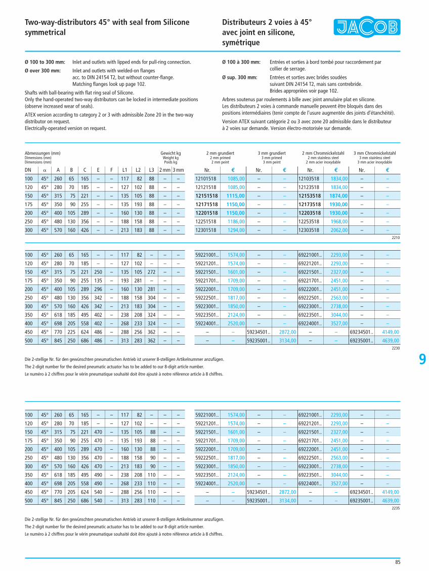
Two-way-distributors 45° with seal from Siliconesymmetrical
Distributeurs 2 voies à 45°avec joint en silicone, symétrique
9
Ø 100 to 300 mm: Inlet and outlets with lipped ends for pull-ring connection.
Ø over 300 mm: Inlet and outlets with welded-on flanges acc. to DIN 24154 T2, but without counter-flange.Matching flanges look up page 102.
Shafts with ball-bearing with flat ring seal of Silicone.Only the hand-operated two-way distributors can be locked in intermediate positions(observe increased wear of seals).
ATEX version according to category 2 or 3 with admissible Zone 20 in the two-waydistributor on request.Electrically-operated version on request.
Ø 100 à 300 mm: Entrées et sorties à bord tombé pour raccordement parcollier de serrage.
Ø sup. 300 mm: Entrées et sorties avec brides soudées suivant DIN 24154 T2, mais sans contrebride.Brides appropriées voir page 102.
Arbres soutenus par roulements à bille avec joint annulaire plat en silicone. Les distributeurs 2 voies à commande manuelle peuvent être bloqués dans despositions intermédiaires (tenir compte de l’usure augmentée des joints d’étanchéité).
Version ATEX suivant catégorie 2 ou 3 avec zone 20 admissible dans le distributeur à 2 voies sur demande. Version électro-motorisée sur demande.
100 45° 260 65 165 – – 117 82 88 – –
120 45° 280 70 185 – – 127 102 88 – –
150 45° 315 75 221 – – 135 105 88 – –
175 45° 350 90 255 – – 135 193 88 – –
200 45° 400 105 289 – – 160 130 88 – –
250 45° 480 130 356 – – 188 158 88 – –
300 45° 570 160 426 – – 213 183 88 – –
Abmessungen (mm) Gewicht kgDimensions (mm) Weight kgDimensions (mm) Poids kg
DN B A B C E F L1 L2 L3 2 mm 3 mm
2 mm grundiert 3 mm grundiert 2 mm Chromnickelstahl 3 mm Chromnickelstahl2 mm primed 3 mm primed 2 mm stainless steel 3 mm stainless steel2 mm peint 3 mm peint 2 mm acier inoxydable 3 mm acier inoxydable
Nr. € Nr. € Nr. € Nr. €
2210
12101518 1085,00
12121518 1085,00
12151518 1115,00
12171518 1150,00
12201518 1150,00
12251518 1186,00
12301518 1294,00
– –
– –
– –
– –
– –
– –
– –
12103518 1834,00
12123518 1834,00
12153518 1874,00
12173518 1930,00
12203518 1930,00
12253518 1968,00
12303518 2062,00
– –
– –
– –
– –
– –
– –
– –
100 45° 260 65 165 – – 117 82 – – –
120 45° 280 70 185 – – 127 102 – – –
150 45° 315 75 221 250 – 135 105 272 – –
175 45° 350 90 255 135 – 193 281 – –
200 45° 400 105 289 296 – 160 130 281 – –
250 45° 480 130 356 342 – 188 158 304 – –
300 45° 570 160 426 342 – 213 183 304 – –
350 45° 618 185 495 402 – 238 208 324 – –
400 45° 698 205 558 402 – 268 233 324 – –
450 45° 770 225 624 486 – 288 256 362 – –
500 45° 845 250 686 486 – 313 283 362 – –2230
59221001.. 1574,00
59221201.. 1574,00
59221501.. 1601,00
59221701.. 1709,00
59222001.. 1709,00
59222501.. 1817,00
59223001.. 1850,00
59223501.. 2124,00
59224001.. 2520,00
– –
– –
– –
– –
– –
– –
– –
– –
– –
– –
– –
59234501.. 2872,00
59235001.. 3134,00
69221001.. 2293,00
69221201.. 2293,00
69221501.. 2327,00
69221701.. 2451,00
69222001.. 2451,00
69222501.. 2563,00
69223001.. 2738,00
69223501.. 3044,00
69224001.. 3527,00
– –
– –
– –
– –
– –
– –
– –
– –
– –
– –
– –
69234501.. 4149,00
69235001.. 4639,00
100 45° 260 65 165 – – 117 82 – – –
120 45° 280 70 185 – – 127 102 – – –
150 45° 315 75 221 470 – 135 105 88 – –
175 45° 350 90 255 470 – 135 193 88 – –
200 45° 400 105 289 470 – 160 130 88 – –
250 45° 480 130 356 470 – 188 158 90 – –
300 45° 570 160 426 470 – 213 183 90 – –
350 45° 618 185 495 490 – 238 208 110 – –
400 45° 698 205 558 490 – 268 233 110 – –
450 45° 770 205 624 540 – 288 256 110 – –
500 45° 845 250 686 540 – 313 283 110 – –2235
59221001.. 1574,00
59221201.. 1574,00
59221501.. 1601,00
59221701.. 1709,00
59222001.. 1709,00
59222501.. 1817,00
59223001.. 1850,00
59223501.. 2124,00
59224001.. 2520,00
– –
– –
– –
– –
– –
– –
– –
– –
– –
– –
– –
59234501.. 2872,00
59235001.. 3134,00
69221001.. 2293,00
69221201.. 2293,00
69221501.. 2327,00
69221701.. 2451,00
69222001.. 2451,00
69222501.. 2563,00
69223001.. 2738,00
69223501.. 3044,00
69224001.. 3527,00
– –
– –
– –
– –
– –
– –
– –
– –
– –
– –
– –
69234501.. 4149,00
69235001.. 4639,00
Die 2-stellige Nr. für den gewünschten pneumatischen Antrieb ist unserer 8-stelligen Artikelnummer anzufügen.
The 2-digit number for the desired pneumatic actuator has to be added to our 8-digit article number.
Le numéro à 2 chiffres pour le vérin pneumatique souhaité doit être ajouté à notre référence article à 8 chiffres.
85
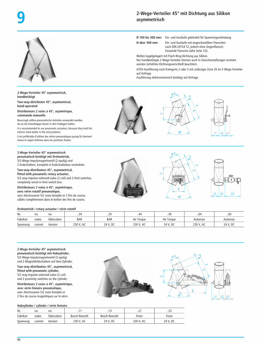
2-Wege-Verteiler 45° mit Dichtung aus Silikonasymmetrisch9
86
Ø 100 bis 300 mm: Ein- und Ausläufe gebördelt für Spannringverbindung.
Ø über 300 mm: Ein- und Ausläufe mit angeschweißten Flanschennach DIN 24154 T2, jedoch ohne Gegenflansch.Passende Flansche siehe Seite 102.
Wellen kugelgelagert mit Flach-Ring-Dichtung aus Silikon.Nur handbetätigte 2-Wege-Verteiler können auch in Zwischenstellungen arretiertwerden (erhöhten Dichtungsverschleiß beachten).
ATEX-Ausführung nach Kategorie 2 oder 3 mit zulässiger Zone 20 im 2-Wege-Verteilerauf Anfrage.Ausführung elektromotorisch betätigt auf Anfrage.
2-Wege-Verteiler 45° asymmetrisch,handbetätigt
Two-way-distributor 45°, asymmetrical,hand-operated
Distributeurs 2 voies à 45°, asymétrique,commande manuelleBevorzugt sollten pneumatische Antriebe verwendet werden,da sie die Innenklappe besser in den Endlagen halten.
It is recommended to use pneumatic actuators, because they hold theinterior valve better in the end positions.
Il est préférable d’utiliser des vérins pneumatiques puisqu’ils tiennentmieux le clapet intérieur dans les positions finales.
A
d
L1 L2
C
L345°
F
B
2-Wege-Verteiler 45° asymmetrischpneumatisch betätigt mit Drehantrieb,5/2-Wege-Impulsmagnetventil (2-spulig) und2 Endschaltern, komplett in Endschalterbox verdrahtet.
Two-way-distributors 45°, asymmetrical,fitted with pneumatic rotary actuator,5/2-way-impulse-solenoid-valve (2 coil) and 2 limit switches,completely wired in limit switch box.
Distributeurs 2 voies à 45°, asymétrique,avec vérin rotatif pneumatique,avec électrovanne 5/2 voies bistable et 2 fins de course, câblés complètement dans le boîtier des fins de course.
A
d
L1 L2
C
L3
45°
F
B
E
A
d
L1 L2
C
L345°
F
B
E
Drehantrieb / rotary actuator / vérin rotatif
Nr. no. no. ..34 ..35 ..44 ..45 ..64 ..65
Fabrikat make fabrication BAR BAR Air Torque Air Torque Automax Automax
Spannung current tension 230 V, AC 24 V, DC 230 V, AC 24 V, DC 230 V, AC 24 V, DC
2-Wege-Verteiler 45° asymmetrischpneumatisch betätigt mit Hubzylinder,5/2-Wege-Impulsmagnetventil (2-spulig)und 2 Magnetfeldschaltern auf dem Zylinder.
Two-way-distributors 45°, asymmetrical,fitted with pneumatic cylinder, 5/2-way-impulse-solenoid-valve (2 coil)and 2 proximity switches on the cylinder.
Distributeurs 2 voies à 45°, asymétrique,avec vérin linéaire pneumatique,avec électrovanne 5/2 voies bistable et2 fins de course magnétiques sur le vérin.
Hubzylinder / cylinder / vérin linéaire
Nr. no. no. ..11 ..13 ..21 ..23
Fabrikat make fabrication Bosch-Rexroth Bosch-Rexroth Festo Festo
Spannung current tension 230 V, AC 24 V, DC 230 V, AC 24 V, DC
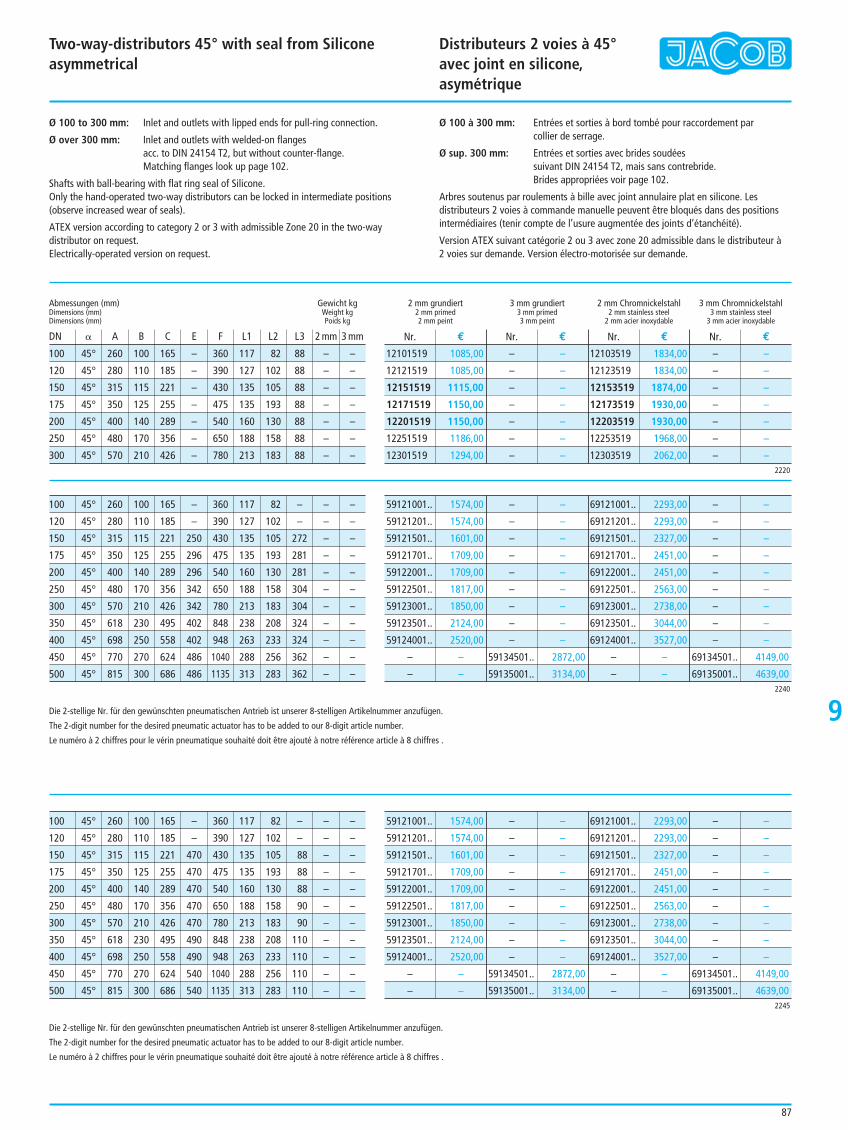
Two-way-distributors 45° with seal from Siliconeasymmetrical
Distributeurs 2 voies à 45°avec joint en silicone, asymétrique
9
Ø 100 to 300 mm: Inlet and outlets with lipped ends for pull-ring connection.
Ø over 300 mm: Inlet and outlets with welded-on flangesacc. to DIN 24154 T2, but without counter-flange.Matching flanges look up page 102.
Shafts with ball-bearing with flat ring seal of Silicone.Only the hand-operated two-way distributors can be locked in intermediate positions(observe increased wear of seals).
ATEX version according to category 2 or 3 with admissible Zone 20 in the two-waydistributor on request.Electrically-operated version on request.
Ø 100 à 300 mm: Entrées et sorties à bord tombé pour raccordement parcollier de serrage.
Ø sup. 300 mm: Entrées et sorties avec brides soudéessuivant DIN 24154 T2, mais sans contrebride.Brides appropriées voir page 102.
Arbres soutenus par roulements à bille avec joint annulaire plat en silicone. Lesdistributeurs 2 voies à commande manuelle peuvent être bloqués dans des positionsintermédiaires (tenir compte de l’usure augmentée des joints d’étanchéité).
Version ATEX suivant catégorie 2 ou 3 avec zone 20 admissible dans le distributeur à 2 voies sur demande. Version électro-motorisée sur demande.
100 45° 260 100 165 – 360 117 82 88 – –
120 45° 280 110 185 – 390 127 102 88 – –
150 45° 315 115 221 – 430 135 105 88 – –
175 45° 350 125 255 – 475 135 193 88 – –
200 45° 400 140 289 – 540 160 130 88 – –
250 45° 480 170 356 – 650 188 158 88 – –
300 45° 570 210 426 – 780 213 183 88 – –
Abmessungen (mm) Gewicht kgDimensions (mm) Weight kgDimensions (mm) Poids kg
DN B A B C E F L1 L2 L3 2 mm 3 mm
2 mm grundiert 3 mm grundiert 2 mm Chromnickelstahl 3 mm Chromnickelstahl2 mm primed 3 mm primed 2 mm stainless steel 3 mm stainless steel2 mm peint 3 mm peint 2 mm acier inoxydable 3 mm acier inoxydable
Nr. € Nr. € Nr. € Nr. €
2220
12101519 1085,00
12121519 1085,00
12151519 1115,00
12171519 1150,00
12201519 1150,00
12251519 1186,00
12301519 1294,00
– –
– –
– –
– –
– –
– –
– –
12103519 1834,00
12123519 1834,00
12153519 1874,00
12173519 1930,00
12203519 1930,00
12253519 1968,00
12303519 2062,00
– –
– –
– –
– –
– –
– –
– –
100 45° 260 100 165 – 360 117 82 – – –
120 45° 280 110 185 – 390 127 102 – – –
150 45° 315 115 221 250 430 135 105 272 – –
175 45° 350 125 255 296 475 135 193 281 – –
200 45° 400 140 289 296 540 160 130 281 – –
250 45° 480 170 356 342 650 188 158 304 – –
300 45° 570 210 426 342 780 213 183 304 – –
350 45° 618 230 495 402 848 238 208 324 – –
400 45° 698 250 558 402 948 263 233 324 – –
450 45° 770 270 624 486 1040 288 256 362 – –
500 45° 815 300 686 486 1135 313 283 362 – –2240
59121001.. 1574,00
59121201.. 1574,00
59121501.. 1601,00
59121701.. 1709,00
59122001.. 1709,00
59122501.. 1817,00
59123001.. 1850,00
59123501.. 2124,00
59124001.. 2520,00
– –
– –
– –
– –
– –
– –
– –
– –
– –
– –
– –
59134501.. 2872,00
59135001.. 3134,00
69121001.. 2293,00
69121201.. 2293,00
69121501.. 2327,00
69121701.. 2451,00
69122001.. 2451,00
69122501.. 2563,00
69123001.. 2738,00
69123501.. 3044,00
69124001.. 3527,00
– –
– –
– –
– –
– –
– –
– –
– –
– –
– –
– –
69134501.. 4149,00
69135001.. 4639,00
100 45° 260 100 165 – 360 117 82 – – –
120 45° 280 110 185 – 390 127 102 – – –
150 45° 315 115 221 470 430 135 105 88 – –
175 45° 350 125 255 470 475 135 193 88 – –
200 45° 400 140 289 470 540 160 130 88 – –
250 45° 480 170 356 470 650 188 158 90 – –
300 45° 570 210 426 470 780 213 183 90 – –
350 45° 618 230 495 490 848 238 208 110 – –
400 45° 698 250 558 490 948 263 233 110 – –
450 45° 770 270 624 540 1040 288 256 110 – –
500 45° 815 300 686 540 1135 313 283 110 – –2245
59121001.. 1574,00
59121201.. 1574,00
59121501.. 1601,00
59121701.. 1709,00
59122001.. 1709,00
59122501.. 1817,00
59123001.. 1850,00
59123501.. 2124,00
59124001.. 2520,00
– –
– –
– –
– –
– –
– –
– –
– –
– –
– –
– –
59134501.. 2872,00
59135001.. 3134,00
69121001.. 2293,00
69121201.. 2293,00
69121501.. 2327,00
69121701.. 2451,00
69122001.. 2451,00
69122501.. 2563,00
69123001.. 2738,00
69123501.. 3044,00
69124001.. 3527,00
– –
– –
– –
– –
– –
– –
– –
– –
– –
– –
– –
69134501.. 4149,00
69135001.. 4639,00
Die 2-stellige Nr. für den gewünschten pneumatischen Antrieb ist unserer 8-stelligen Artikelnummer anzufügen.
The 2-digit number for the desired pneumatic actuator has to be added to our 8-digit article number.
Le numéro à 2 chiffres pour le vérin pneumatique souhaité doit être ajouté à notre référence article à 8 chiffres .
87
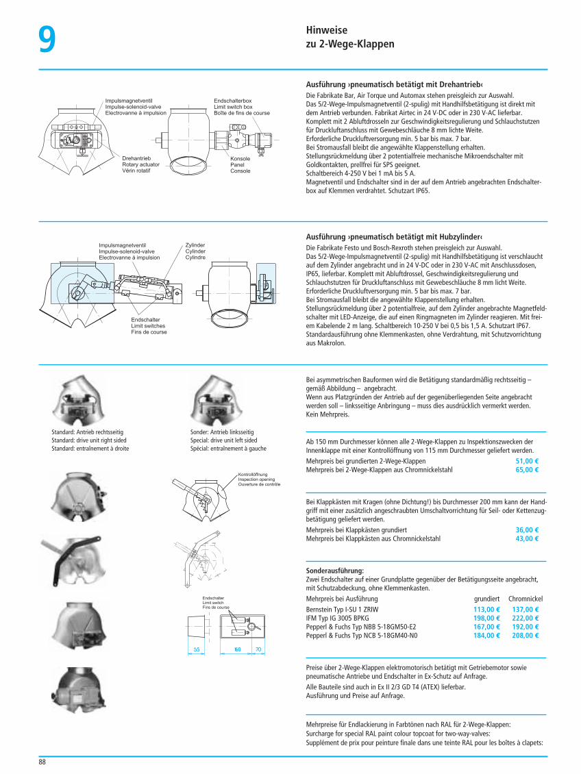
Hinweise zu 2-Wege-Klappen9
88
Ausführung ›pneumatisch betätigt mit Drehantrieb‹Die Fabrikate Bar, Air Torque und Automax stehen preisgleich zur Auswahl.Das 5/2-Wege-Impulsmagnetventil (2-spulig) mit Handhilfsbetätigung ist direkt mitdem Antrieb verbunden. Fabrikat Airtec in 24 V-DC oder in 230 V-AC lieferbar.Komplett mit 2 Abluftdrosseln zur Geschwindigkeitsregulierung und Schlauchstutzenfür Druckluftanschluss mit Gewebeschläuche 8 mm lichte Weite.Erforderliche Druckluftversorgung min. 5 bar bis max. 7 bar.Bei Stromausfall bleibt die angewählte Klappenstellung erhalten.Stellungsrückmeldung über 2 potentialfreie mechanische Mikroendschalter mitGoldkontakten, prellfrei für SPS geeignet.Schaltbereich 4-250 V bei 1 mA bis 5 A.Magnetventil und Endschalter sind in der auf dem Antrieb angebrachten Endschalter-box auf Klemmen verdrahtet. Schutzart IP65.
Endschalterbox
Limit switch box
Boîte de fins de course
Konsole
Panel
Console
Drehantrieb
Rotary actuator
Vérin rotatif
Impulsmagnetventil
Impulse-solenoid-valve
Electrovanne à impulsion
KontrollöffnungInspection openingOuverture de contrôle
EndschalterLimit switchFins de course
Ausführung ›pneumatisch betätigt mit Hubzylinder‹Die Fabrikate Festo und Bosch-Rexroth stehen preisgleich zur Auswahl.Das 5/2-Wege-Impulsmagnetventil (2-spulig) mit Handhilfsbetätigung ist verschlauchtauf dem Zylinder angebracht und in 24 V-DC oder in 230 V-AC mit Anschlussdosen,IP65, lieferbar. Komplett mit Abluftdrossel, Geschwindigkeitsregulierung undSchlauchstutzen für Druckluftanschluss mit Gewebeschläuche 8 mm licht Weite.Erforderliche Druckluftversorgung min. 5 bar bis max. 7 bar. Bei Stromausfall bleibt die angewählte Klappenstellung erhalten.Stellungsrückmeldung über 2 potentialfreie, auf dem Zylinder angebrachte Magnetfeld-schalter mit LED-Anzeige, die auf einen Ringmagneten im Zylinder reagieren. Mit frei-em Kabelende 2 m lang. Schaltbereich 10-250 V bei 0,5 bis 1,5 A. Schutzart IP67.Standardausführung ohne Klemmenkasten, ohne Verdrahtung, mit Schutzvorrichtungaus Makrolon.
Bei asymmetrischen Bauformen wird die Betätigung standardmäßig rechtsseitig –gemäß Abbildung – angebracht.Wenn aus Platzgründen der Antrieb auf der gegenüberliegenden Seite angebrachtwerden soll – linksseitige Anbringung – muss dies ausdrücklich vermerkt werden. Kein Mehrpreis.
Ab 150 mm Durchmesser können alle 2-Wege-Klappen zu Inspektionszwecken derInnenklappe mit einer Kontrollöffnung von 115 mm Durchmesser geliefert werden.Mehrpreis bei grundierten 2-Wege-Klappen 51,00 €Mehrpreis bei 2-Wege-Klappen aus Chromnickelstahl 65,00 €
Bei Klappkästen mit Kragen (ohne Dichtung!) bis Durchmesser 200 mm kann der Hand-griff mit einer zusätzlich angeschraubten Umschaltvorrichtung für Seil- oder Kettenzug-betätigung geliefert werden.Mehrpreis bei Klappkästen grundiert 36,00 €Mehrpreis bei Klappkästen aus Chromnickelstahl 43,00 €
Sonderausführung:Zwei Endschalter auf einer Grundplatte gegenüber der Betätigungsseite angebracht,mit Schutzabdeckung, ohne Klemmenkasten.Mehrpreis bei Ausführung grundiert ChromnickelBernstein Typ I-SU 1 ZRIW 113,00 € 137,00 €IFM Typ IG 3005 BPKG 198,00 € 222,00 €Pepperl & Fuchs Typ NBB 5-18GM50-E2 167,00 € 192,00 €Pepperl & Fuchs Typ NCB 5-18GM40-N0 184,00 € 208,00 €
Preise über 2-Wege-Klappen elektromotorisch betätigt mit Getriebemotor sowiepneumatische Antriebe und Endschalter in Ex-Schutz auf Anfrage.Alle Bauteile sind auch in Ex II 2/3 GD T4 (ATEX) lieferbar.Ausführung und Preise auf Anfrage.
Mehrpreise für Endlackierung in Farbtönen nach RAL für 2-Wege-Klappen:Surcharge for special RAL paint colour topcoat for two-way-valves:Supplément de prix pour peinture finale dans une teinte RAL pour les boîtes à clapets:
Standard: Antrieb rechtsseitigStandard: drive unit right sidedStandard: entraînement à droite
Sonder: Antrieb linksseitigSpecial: drive unit left sidedSpécial: entraînement à gauche
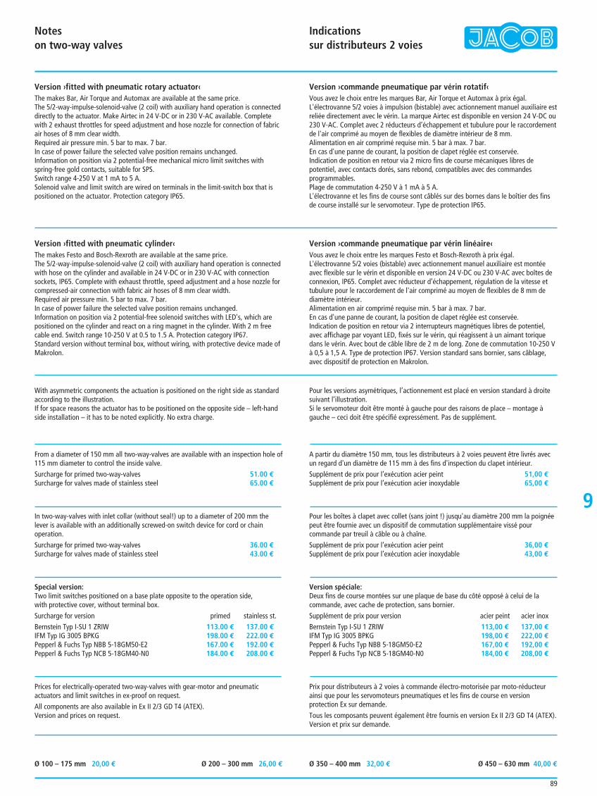
Notes on two-way valves
Indications sur distributeurs 2 voies
9
89
Version ›fitted with pneumatic rotary actuator‹The makes Bar, Air Torque and Automax are available at the same price.The 5/2-way-impulse-solenoid-valve (2 coil) with auxiliary hand operation is connecteddirectly to the actuator. Make Airtec in 24 V-DC or in 230 V-AC available. Completewith 2 exhaust throttles for speed adjustment and hose nozzle for connection of fabricair hoses of 8 mm clear width.Required air pressure min. 5 bar to max. 7 bar. In case of power failure the selected valve position remains unchanged.Information on position via 2 potential-free mechanical micro limit switches withspring-free gold contacts, suitable for SPS.Switch range 4-250 V at 1 mA to 5 A.Solenoid valve and limit switch are wired on terminals in the limit-switch box that ispositioned on the actuator. Protection category IP65.
Version ›commande pneumatique par vérin rotatif‹Vous avez le choix entre les marques Bar, Air Torque et Automax à prix égal.L'électrovanne 5/2 voies à impulsion (bistable) avec actionnement manuel auxiliaire estreliée directement avec le vérin. La marque Airtec est disponible en version 24 V-DC ou230 V-AC. Complet avec 2 réducteurs d’échappement et tubulure pour le raccordementde l'air comprimé au moyen de flexibles de diamètre intérieur de 8 mm.Alimentation en air comprimé requise min. 5 bar à max. 7 bar. En cas d'une panne de courant, la position de clapet réglée est conservée.Indication de position en retour via 2 micro fins de course mécaniques libres depotentiel, avec contacts dorés, sans rebond, compatibles avec des commandesprogrammables. Plage de commutation 4-250 V à 1 mA à 5 A.L'électrovanne et les fins de course sont câblés sur des bornes dans le boîtier des finsde course installé sur le servomoteur. Type de protection IP65.
Version ›fitted with pneumatic cylinder‹The makes Festo and Bosch-Rexroth are available at the same price.The 5/2-way-impulse-solenoid-valve (2 coil) with auxiliary hand operation is connectedwith hose on the cylinder and available in 24 V-DC or in 230 V-AC with connectionsockets, IP65. Complete with exhaust throttle, speed adjustment and a hose nozzle forcompressed-air connection with fabric air hoses of 8 mm clear width.Required air pressure min. 5 bar to max. 7 bar. In case of power failure the selected valve position remains unchanged.Information on position via 2 potential-free solenoid switches with LED's, which arepositioned on the cylinder and react on a ring magnet in the cylinder. With 2 m freecable end. Switch range 10-250 V at 0.5 to 1.5 A. Protection category IP67. Standard version without terminal box, without wiring, with protective device made ofMakrolon.
With asymmetric components the actuation is positioned on the right side as standardaccording to the illustration.If for space reasons the actuator has to be positioned on the opposite side – left-handside installation – it has to be noted explicitly. No extra charge.
From a diameter of 150 mm all two-way-valves are available with an inspection hole of115 mm diameter to control the inside valve.Surcharge for primed two-way-valves 51.00 €Surcharge for valves made of stainless steel 65.00 €
In two-way-valves with inlet collar (without seal!) up to a diameter of 200 mm thelever is available with an additionally screwed-on switch device for cord or chainoperation.Surcharge for primed two-way-valves 36.00 €Surcharge for valves made of stainless steel 43.00 €
Special version:Two limit switches positioned on a base plate opposite to the operation side, with protective cover, without terminal box.Surcharge for version primed stainless st.Bernstein Typ I-SU 1 ZRIW 113.00 € 137.00 €IFM Typ IG 3005 BPKG 198.00 € 222.00 €Pepperl & Fuchs Typ NBB 5-18GM50-E2 167.00 € 192.00 €Pepperl & Fuchs Typ NCB 5-18GM40-N0 184.00 € 208.00 €
Prices for electrically-operated two-way-valves with gear-motor and pneumaticactuators and limit switches in ex-proof on request.All components are also available in Ex II 2/3 GD T4 (ATEX).Version and prices on request.
Version ›commande pneumatique par vérin linéaire‹Vous avez le choix entre les marques Festo et Bosch-Rexroth à prix égal.L'électrovanne 5/2 voies (bistable) avec actionnement manuel auxiliaire est montéeavec flexible sur le vérin et disponible en version 24 V-DC ou 230 V-AC avec boîtes deconnexion, IP65. Complet avec réducteur d’échappement, régulation de la vitesse ettubulure pour le raccordement de l'air comprimé au moyen de flexibles de 8 mm dediamètre intérieur.Alimentation en air comprimé requise min. 5 bar à max. 7 bar.En cas d'une panne de courant, la position de clapet réglée est conservée.Indication de position en retour via 2 interrupteurs magnétiques libres de potentiel,avec affichage par voyant LED, fixés sur le vérin, qui réagissent à un aimant toriquedans le vérin. Avec bout de câble libre de 2 m de long. Zone de commutation 10-250 Và 0,5 à 1,5 A. Type de protection IP67. Version standard sans bornier, sans câblage,avec dispositif de protection en Makrolon.
Pour les versions asymétriques, l’actionnement est placé en version standard à droitesuivant l’illustration.Si le servomoteur doit être monté à gauche pour des raisons de place – montage àgauche – ceci doit être spécifié expressément. Pas de supplément.
A partir du diamètre 150 mm, tous les distributeurs à 2 voies peuvent être livrés avecun regard d'un diamètre de 115 mm à des fins d'inspection du clapet intérieur.Supplément de prix pour l’exécution acier peint 51,00 €Supplément de prix pour l’exécution acier inoxydable 65,00 €
Pour les boîtes à clapet avec collet (sans joint !) jusqu'au diamètre 200 mm la poignéepeut être fournie avec un dispositif de commutation supplémentaire vissé pourcommande par treuil à câble ou à chaîne.Supplément de prix pour l’exécution acier peint 36,00 €Supplément de prix pour l’exécution acier inoxydable 43,00 €
Version spéciale:Deux fins de course montées sur une plaque de base du côté opposé à celui de lacommande, avec cache de protection, sans bornier.Supplément de prix pour version acier peint acier inoxBernstein Typ I-SU 1 ZRIW 113,00 € 137,00 €IFM Typ IG 3005 BPKG 198,00 € 222,00 €Pepperl & Fuchs Typ NBB 5-18GM50-E2 167,00 € 192,00 €Pepperl & Fuchs Typ NCB 5-18GM40-N0 184,00 € 208,00 €
Prix pour distributeurs à 2 voies à commande électro-motorisée par moto-réducteurainsi que pour les servomoteurs pneumatiques et les fins de course en versionprotection Ex sur demande.Tous les composants peuvent également être fournis en version Ex II 2/3 GD T4 (ATEX).Version et prix sur demande.
Ø 100 – 175 mm 20,00 € Ø 200 – 300 mm 26,00 € Ø 350 – 400 mm 32,00 € Ø 450 – 630 mm 40,00 €
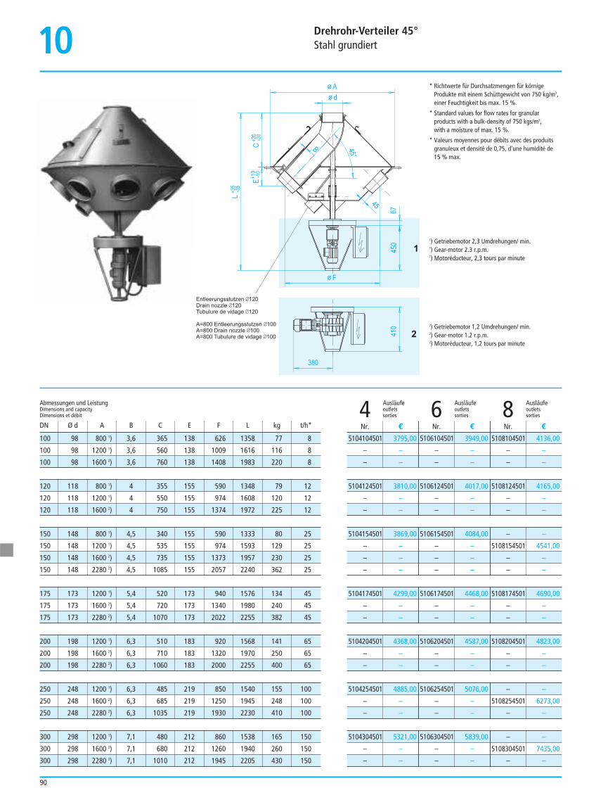
Drehrohr-Verteiler 45°Stahl grundiert
90
10* Richtwerte für Durchsatzmengen für körnige
Produkte mit einem Schüttgewicht von 750 kg/m3,einer Feuchtigkeit bis max. 15 %.
* Standard values for flow rates for granularproducts with a bulk-density of 750 kgs/m3, with a moisture of max. 15 %.
* Valeurs moyennes pour débits avec des produitsgranuleux et densité de 0,75, d’une humidité de 15 % max.
1) Getriebemotor 2,3 Umdrehungen/ min.1) Gear-motor 2.3 r.p.m.1) Motoréducteur, 2,3 tours par minute
2) Getriebemotor 1,2 Umdrehungen/ min.2) Gear-motor 1.2 r.p.m.2) Motoréducteur, 1,2 tours par minute
Ausläufe Ausläufe Ausläufeoutlets outlets outlets4 sorties 6 sorties 8 sorties
5104104501 3795,00
– –
– –
5106104501 3949,00
– –
– –
5108104501 4136,00
– –
– –
5104124501 3810,00
– –
– –
5106124501 4017,00
– –
– –
5108124501 4165,00
– –
– –
5104154501 3869,00
– –
– –
– –
5106154501 4084,00
– –
– –
– –
– –
5108154501 4541,00
– –
– –
5104174501 4299,00
– –
– –
5106174501 4468,00
– –
– –
5108174501 4690,00
– –
– –
5104204501 4368,00
– –
– –
5106204501 4587,00
– –
– –
5108204501 4823,00
– –
– –
5104254501 4885,00
– –
– –
5106254501 5076,00
– –
– –
– –
5108254501 6273,00
– –
5104304501 5321,00
– –
– –
5106304501 5839,00
– –
– –
– –
5108304501 7435,00
– –
Nr. € Nr. € Nr. €
100 98 800 1) 3,6 365 138 626 1358 77 8
100 98 1200 1) 3,6 560 138 1009 1616 116 8
100 98 1600 2) 3,6 760 138 1408 1983 220 8
120 118 800 1) 4 355 155 590 1348 79 12
120 118 1200 1) 4 550 155 974 1608 120 12
120 118 1600 2) 4 750 155 1374 1972 225 12
150 148 800 1) 4,5 340 155 590 1333 80 25
150 148 1200 1) 4,5 535 155 974 1593 129 25
150 148 1600 2) 4,5 735 155 1373 1957 230 25
150 148 2280 2) 4,5 1085 155 2057 2240 362 25
175 173 1200 1) 5,4 520 173 940 1576 134 45
175 173 1600 2) 5,4 720 173 1340 1980 240 45
175 173 2280 2) 5,4 1070 173 2022 2255 382 45
200 198 1200 1) 6,3 510 183 920 1568 141 65
200 198 1600 2) 6,3 710 183 1320 1970 250 65
200 198 2280 2) 6,3 1060 183 2000 2255 400 65
250 248 1200 1) 6,3 485 219 850 1540 155 100
250 248 1600 2) 6,3 685 219 1250 1945 248 100
250 248 2280 2) 6,3 1035 219 1930 2230 410 100
300 298 1200 1) 7,1 480 212 860 1538 165 150
300 298 1600 2) 7,1 680 212 1260 1940 260 150
300 298 2280 2) 7,1 1010 212 1945 2205 430 150
Abmessungen und LeistungDimensions and capacityDimensions et débit
DN Ø d A B C E F L kg t/h*
1
2
F
410
67
L
EC
A
d
380
450
45
45°
B
+20
-20
+35
-35
+10
-10
Entleerungsstutzen 120
Drain nozzle 120
Tubulure de vidage 120
A=800 Entleerungsstutzen 100
A=800 Drain nozzle 100
A=800 Tubulure de vidage 100

Turn-head distributors 45°Primed steel
Distributeurs rotatifs 45°Acier peint
91
10
Zur Verteilung von Getreide und körnigen Schüttgüternim freien Fall, ohne Überdruck im Rohrsystem undohne Anspruch auf Staubdichtheit.Produktführung von oben durch Drehrohr auf dengewünschten Auslauf innerhalb eines geschlossenenGehäuses. Anpressung der Drehrohrdichtung mit 2 Druckfedern.Abstützung durch vier Konsolen am Untertrichter-umfang gemäß Maßblatt.Antrieb elektrisch mit Getriebemotor, Motorspannung230/400 Volt, 50 bis 60 Hz.Steuerung durch mechanische Endschalter, imAnschlusskasten auf Klemmen geführt. Näherungsendschalter gegen Mehrpreis.Drehrohrverteiler darf nicht im Produktstromgeschaltet werden.Alle Maßangaben sind ca.-Abmessungen.Zusätzliche elektrische Anpress- und Positionskontrolleder Drehrohrauslaufstellung mit Näherungsendschal-tern, im Gehäuseunterteil eingebaut, gegen Mehrpreislieferbar.Produktberührende Teile aus Chromnickelstahl gegenMehrpreis lieferbar.
ATEX-Ausführungen nach Kategorie 2 oder 3 mitzulässiger Zone 20 im Drehrohr auf Anfrage.
For distributing grain and granular products by gravitywithout overpressure inside of the pipe-system andwith no demand for dust-tightness internally.Feeding from the top through the turn-pipe towardsthe requested outlet inside of a closed casing.Pressing-on of the rotary pipe seal by means of 2pressure springs.Support by means of four lugs, fixed to the lowerfunnel circumference according data-sheet.Electrically operated by means of a gear-motor, motor-current 230/400 Volt, 50 to 60 Hz.Positioning by means of mechanical limit-switches,wired on terminals in a connecting box.Proximity switches with surcharge.Turn-head distributor must not be operated whentransporting material.All dimensions are approximate.Additional electric pressing and position control of theturn-pipes outlet position with proximity-switches,fixed into the lower funnel, with surcharge.Product-contacting parts made of stainless steel withsurcharge.
ATEX versions according to category 2 or 3 withadmissible Zone 20 in turn-pipe on request.
Pour la distribution gravitaire de produits en vracgranuleux et céréales, sans pression et sans exigenceparticulière quant à l’étanchéité aux fines.Guidage du produit par tuyau rotatif sur la sortiesouhaitée à l’intérieur d’un corps totalement fermé.Appui du joint tournant par 2 ressorts à pression.Support par quatre cornières situées sur la trémieinférieure suivant plan d’encombrement.Entraînement par motoréducteur, tension moteur230/400 Volt, 50 à 60 Hz.Positionnement par fins de course mécaniques câbléssur bornes dans la boîte des connexions.Détecteur de proximité en option.Le distributeur ne doit pas être actionné en charge.Les dimensions sont indicatives.Contrôle électrique supplémentaire d’appui et deposition du tuyau rotatif par détecteurs de proximitésitués dans la partie inférieure du corps contre plus-value.Pièces en contact avec le produit en acier inoxydablecontre plus-value.
Versions ATEX suivant catégorie 2 ou 3 avec zone 20admissible dans le tuyau rotatif sur demande.
Ausläufe Ausläufe Ausläufe Ausläufe Ausläufe Ausläufeoutlets outlets outlets outlets outlets outlets10 sorties 12 sorties 14 sorties 16 sorties 18 sorties 20 sorties
5110104501 4338,00
– –
– –
100 800 1)
100 1200 1)
100 1600 2)
120 800 1)
120 1200 1)
120 1600 2)
150 800 1)
150 1200 1)
150 1600 2)
150 2280 2)
175 1200 1)
175 1600 2)
175 2280 2)
200 1200 1)
200 1600 2)
200 2280 2)
250 1200 1)
250 1600 2)
250 2280 2)
300 1200 1)
300 1600 2)
300 2280 2)
– –
5112104501 4812,00
– –
– –
5114104501 5264,00
– –
– –
5116104501 5380,00
– –
– –
5118104501 5606,00
– –
– –
– –
5120104501 7190,00
– –
5110124501 4743,00
– –
– –
5112124501 4956,00
– –
– –
5114124501 5283,00
– –
– –
– –
5116124501 6651,00
– –
– –
5118124501 6999,00
– –
– –
5120124501 7253,00
– –
5110154501 4861,00
– –
– –
– –
5112154501 5080,00
– –
– –
– –
– –
5114154501 6688,00
– –
– –
– –
5116154501 6857,00
– –
– –
– –
5118154501 7082,00
– –
– –
– –
– –
5120154501 9528,00
5110174501 4910,00
– –
– –
– –
5112174501 6565,00
– –
– –
5114174501 6792,00
– –
– –
5116174501 7028,00
– –
– –
– –
5118174501 9673,00
– –
– –
5120174501 9914,00
5110204501 5054,00
– –
– –
– –
5112204501 6688,00
– –
– –
5114204501 6929,00
– –
– –
– –
5116204501 9504,00
– –
– –
5118204501 9714,00
– –
– –
5120204501 9953,00
– –
5110254501 6509,00
– –
– –
– –
5112254501 9380,00
– –
– –
5114254501 9608,00
– –
– –
5116254501 9858,00
– –
– –
– –
– –
– –
– –
– –
5110304501 7673,00
– –
– –
– –
5112304501 10818,00
– –
– –
5114304501 11267,00
– –
– –
– –
– –
– –
– –
– –
– –
– –
Nr. € Nr. € Nr. € Nr. € Nr. € Nr. €DN A
2320
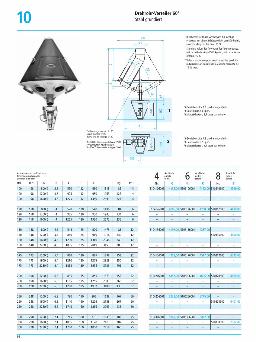
10 Drehrohr-Verteiler 60°Stahl grundiert
92
1
2
380
F
450
67
45L E
C
B
Ad
410
Entleerungsstutzen 120Drain nozzle 120Tubulure de vidage 120
A=800 Entleerungsstutzen 100A=800 Drain nozzle 100A=800 Tubulure de vidage 100
60°
* Richtwerte für Durchsatzmengen für mehligeProdukte mit einem Schüttgewicht von 500 kg/m3,einer Feuchtigkeit bis max. 15 %.
* Standard values for flow rates for floury productswith a bulk-density of 500 kgs/m3, with a moistureof max. 15 %.
* Valeurs moyennes pour débits avec des produitspulvérulents et densité de 0,5, d’une humidité de15 % max.
1) Getriebemotor 2,3 Umdrehungen/ min.1) Gear-motor 2.3 r.p.m.1) Motoréducteur, 2,3 tours par minute
2) Getriebemotor 1,2 Umdrehungen/ min.2) Gear-motor 1.2 r.p.m.2) Motoréducteur, 1,2 tours par minute
Ausläufe Ausläufe Ausläufeoutlets outlets outlets4 sorties 6 sorties 8 sorties
5104106001 4136,00
– –
– –
5106106001 4162,00
– –
– –
5108106001 4399,00
– –
– –
5104126001 4186,00
– –
– –
5106126001 4260,00
– –
– –
5108126001 4418,00
– –
– –
5104156001 4197,00
– –
– –
– –
5106156001 4287,00
– –
– –
– –
– –
5108156001 4650,00
– –
– –
5104176001 4358,00
– –
– –
5106176001 4527,00
– –
– –
5108176001 4743,00
– –
– –
5104206001 4458,00
– –
– –
5106206001 4605,00
– –
– –
5108206001 4850,00
– –
– –
5104256001 5038,00
– –
– –
5106256001 5775,00
– –
– –
– –
5108256001 6401,00
– –
5104306001 5960,00
– –
– –
5106306001 6442,00
– –
– –
– –
5108306001 7532,00
– –
Nr. € Nr. € Nr. €
100 98 800 1) 3,6 590 112 560 1518 82 4
100 98 1200 1) 3,6 925 112 950 1963 127 4
100 98 1600 2) 3,6 1275 112 1350 2393 227 4
120 118 800 1) 4 570 120 540 1498 84 6
120 118 1200 1) 4 905 120 930 1943 134 6
120 118 1600 2) 4 1255 120 1330 2373 235 6
150 148 800 1) 4,5 545 125 520 1473 85 12
150 148 1200 1) 4,5 880 125 910 1918 140 12
150 148 1600 2) 4,5 1230 125 1310 2348 240 12
150 148 2280 2) 4,5 1835 125 2019 3153 380 12
175 173 1200 1) 5,4 860 130 875 1898 153 22
175 173 1600 2) 5,4 1210 130 1275 2328 250 22
175 173 2280 2) 5,4 1815 130 1954 3133 405 22
200 198 1200 1) 6,3 835 135 855 1873 153 32
200 198 1600 2) 6,3 1185 135 1255 2303 265 32
200 198 2280 2) 6,3 1790 135 1937 3108 430 32
250 248 1200 1) 6,3 790 150 805 1688 167 50
250 248 1600 2) 6,3 1140 150 1205 2158 267 50
250 248 2280 2) 6,3 1745 150 1885 2963 435 50
300 298 1200 1) 7,1 745 160 770 1643 182 75
300 298 1600 2) 7,1 1095 160 1170 2113 287 75
300 298 2280 2) 7,1 1700 160 1850 2918 460 75
Abmessungen und LeistungDimensions and capacityDimensions et débit
DN Ø d A B C E F L kg t/h*
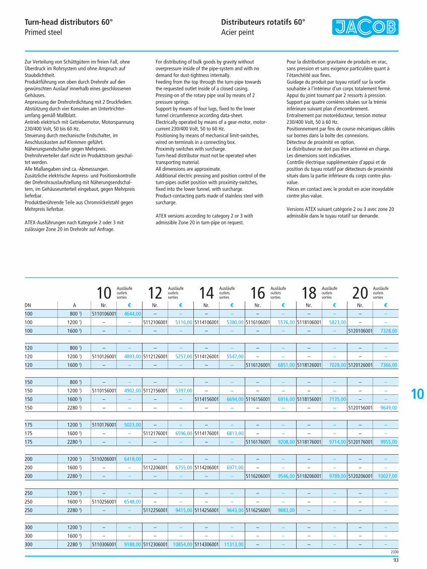
10
Turn-head distributors 60°Primed steel
Distributeurs rotatifs 60°Acier peint
93
Zur Verteilung von Schüttgütern im freien Fall, ohneÜberdruck im Rohrsystem und ohne Anspruch aufStaubdichtheit.Produktführung von oben durch Drehrohr auf dengewünschten Auslauf innerhalb eines geschlossenenGehäuses. Anpressung der Drehrohrdichtung mit 2 Druckfedern.Abstützung durch vier Konsolen am Untertrichter-umfang gemäß Maßblatt.Antrieb elektrisch mit Getriebemotor, Motorspannung230/400 Volt, 50 bis 60 Hz.Steuerung durch mechanische Endschalter, imAnschlusskasten auf Klemmen geführt. Näherungsendschalter gegen Mehrpreis.Drehrohrverteiler darf nicht im Produktstrom geschal-tet werden.Alle Maßangaben sind ca.-Abmessungen.Zusätzliche elektrische Anpress- und Positionskontrolleder Drehrohrauslaufstellung mit Näherungsendschal-tern, im Gehäuseunterteil eingebaut, gegen Mehrpreislieferbar.Produktberührende Teile aus Chromnickelstahl gegenMehrpreis lieferbar.
ATEX-Ausführungen nach Kategorie 2 oder 3 mitzulässiger Zone 20 im Drehrohr auf Anfrage.
For distributing of bulk goods by gravity withoutoverpressure inside of the pipe-system and with nodemand for dust-tightness internally.Feeding from the top through the turn-pipe towardsthe requested outlet inside of a closed casing.Pressing-on of the rotary pipe seal by means of 2pressure springs.Support by means of four lugs, fixed to the lowerfunnel circumference according data-sheet.Electrically operated by means of a gear-motor, motor-current 230/400 Volt, 50 to 60 Hz.Positioning by means of mechanical limit-switches,wired on terminals in a connecting box. Proximity switches with surcharge.Turn-head distributor must not be operated whentransporting material.All dimensions are approximate.Additional electric pressing and position control of theturn-pipes outlet position with proximity-switches,fixed into the lower funnel, with surcharge.Product-contacting parts made of stainless steel withsurcharge.
ATEX versions according to category 2 or 3 withadmissible Zone 20 in turn-pipe on request.
Pour la distribution gravitaire de produits en vrac, sans pression et sans exigence particulière quant àl’étanchéité aux fines.Guidage du produit par tuyau rotatif sur la sortiesouhaitée à l’intérieur d’un corps totalement fermé.Appui du joint tournant par 2 ressorts à pression.Support par quatre cornières situées sur la trémieinférieure suivant plan d’encombrement.Entraînement par motoréducteur, tension moteur230/400 Volt, 50 à 60 Hz.Positionnement par fins de course mécaniques câbléssur bornes dans la boîte des connexions.Détecteur de proximité en option.Le distributeur ne doit pas être actionné en charge.Les dimensions sont indicatives.Contrôle électrique supplémentaire d’appui et deposition du tuyau rotatif par détecteurs de proximitésitués dans la partie inférieure du corps contre plus-value.Pièces en contact avec le produit en acier inoxydablecontre plus-value.
Versions ATEX suivant catégorie 2 ou 3 avec zone 20admissible dans le tuyau rotatif sur demande.
Ausläufe Ausläufe Ausläufe Ausläufe Ausläufe Ausläufeoutlets outlets outlets outlets outlets outlets10 sorties 12 sorties 14 sorties 16 sorties 18 sorties 20 sorties
5110106001 4644,00
– –
– –
100 800 1)
100 1200 1)
100 1600 2)
120 800 1)
120 1200 1)
120 1600 2)
150 800 1)
150 1200 1)
150 1600 2)
150 2280 2)
175 1200 1)
175 1600 2)
175 2280 2)
200 1200 1)
200 1600 2)
200 2280 2)
250 1200 1)
250 1600 2)
250 2280 2)
300 1200 1)
300 1600 2)
300 2280 2)
– –
5112106001 5116,00
– –
– –
5114106001 5380,00
– –
– –
5116106001 5576,00
– –
– –
5118106001 5823,00
– –
– –
– –
5120106001 7328,00
– –
5110126001 4893,00
– –
– –
5112126001 5257,00
– –
– –
5114126001 5547,00
– –
– –
– –
5116126001 6851,00
– –
– –
5118126001 7028,00
– –
– –
5120126001 7366,00
– –
5110156001 4902,00
– –
– –
– –
5112156001 5397,00
– –
– –
– –
– –
5114156001 6694,00
– –
– –
– –
5116156001 6916,00
– –
– –
– –
5118156001 7135,00
– –
– –
– –
– –
5120156001 9649,00
5110176001 5023,00
– –
– –
– –
5112176001 6596,00
– –
– –
5114176001 6813,00
– –
– –
– –
5116176001 9208,00
– –
– –
5118176001 9714,00
– –
– –
5120176001 9955,00
5110206001 6418,00
– –
– –
– –
5112206001 6755,00
– –
– –
5114206001 6971,00
– –
– –
– –
5116206001 9546,00
– –
– –
5118206001 9789,00
– –
– –
5120206001 10027,00
– –
5110256001 6548,00
– –
– –
– –
5112256001 9415,00
– –
– –
5114256001 9643,00
– –
– –
5116256001 9883,00
– –
– –
– –
– –
– –
– –
– –
– –
5110306001 9188,00
– –
– –
5112306001 10854,00
– –
– –
5114306001 11313,00
– –
– –
– –
– –
– –
– –
– –
– –
– –
Nr. € Nr. € Nr. € Nr. € Nr. € Nr. €DN A
2330
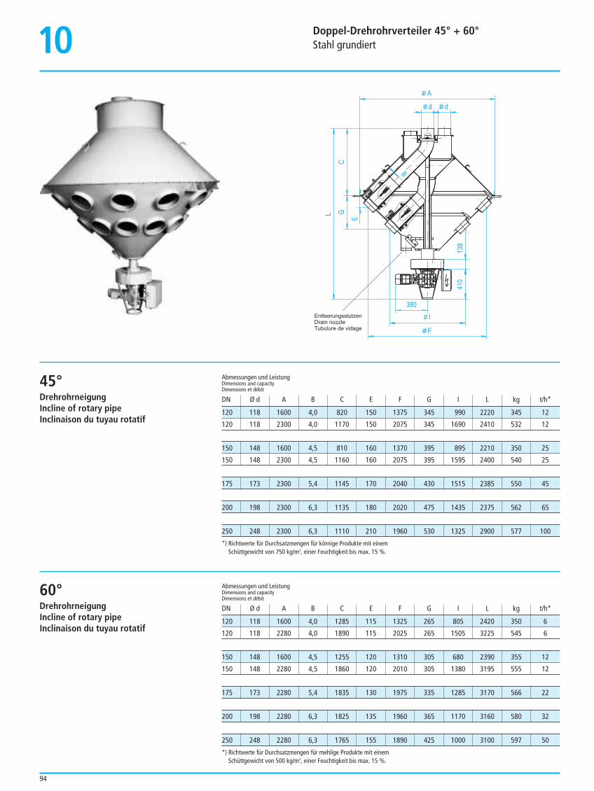
10 Doppel-Drehrohrverteiler 45° + 60°Stahl grundiert
94
120 118 1600 4,0 820 150 1375 345 990 2220 345 12
120 118 2300 4,0 1170 150 2075 345 1690 2410 532 12
150 148 1600 4,5 810 160 1370 395 895 2210 350 25
150 148 2300 4,5 1160 160 2075 395 1595 2400 540 25
175 173 2300 5,4 1145 170 2040 430 1515 2385 550 45
200 198 2300 6,3 1135 180 2020 475 1435 2375 562 65
250 248 2300 6,3 1110 210 1960 530 1325 2900 577 100
Abmessungen und LeistungDimensions and capacityDimensions et débit
DN Ø d A B C E F G I L kg t/h*
F
410
138
L
E
C
B
A
dd
G
I
380EntleerungsstutzenDrain nozzleTubulure de vidage
45°DrehrohrneigungIncline of rotary pipeInclinaison du tuyau rotatif
*) Richtwerte für Durchsatzmengen für körnige Produkte mit einemSchüttgewicht von 750 kg/m3, einer Feuchtigkeit bis max. 15 %.
120 118 1600 4,0 1285 115 1325 265 805 2420 350 6
120 118 2280 4,0 1890 115 2025 265 1505 3225 545 6
150 148 1600 4,5 1255 120 1310 305 680 2390 355 12
150 148 2280 4,5 1860 120 2010 305 1380 3195 555 12
175 173 2280 5,4 1835 130 1975 335 1285 3170 566 22
200 198 2280 6,3 1825 135 1960 365 1170 3160 580 32
250 248 2280 6,3 1765 155 1890 425 1000 3100 597 50
Abmessungen und LeistungDimensions and capacityDimensions et débit
DN Ø d A B C E F G I L kg t/h*
60°DrehrohrneigungIncline of rotary pipeInclinaison du tuyau rotatif
*) Richtwerte für Durchsatzmengen für mehlige Produkte mit einemSchüttgewicht von 500 kg/m3, einer Feuchtigkeit bis max. 15 %.
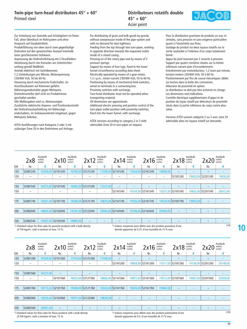
10
Twin-pipe turn-head distributors 45° + 60°Primed steel
Distributeurs rotatifs double 45° + 60°Acier peint
95
Zur Verteilung von Getreide und Schüttgütern im freienFall, ohne Überdruck im Rohrsystem und ohneAnspruch auf Staubdichtheit.Produktführung von oben durch zwei gegenläufigeDrehrohre auf den gewünschten Auslauf innerhalbeines geschlossenen Gehäuses. Anpressung der Drehrohrdichtung mit 2 Druckfedern.Abstützung durch vier Konsolen am Untertrichter-umfang gemäß Maßblatt.Antrieb elektrisch mit Getriebemotor, 1,2 Umdrehungen pro Minute, Motorspannung230/400 Volt, 50 bis 60 Hz.Steuerung durch mechanische Endschalter, imAnschlusskasten auf Klemmen geführt. Näherungsendschalter gegen Mehrpreis.Drehrohrverteiler darf nicht im Produktstromgeschaltet werden.Alle Maßangaben sind ca.-Abmessungen.Zusätzliche elektrische Anpress- und Positionskontrolleder Drehrohrauslaufstellung mit Näherungs-endschaltern, im Gehäuseunterteil eingebaut, gegenMehrpreis lieferbar.
ATEX-Ausführungen nach Kategorie 2 oder 3 mitzulässiger Zone 20 in den Drehrohren auf Anfrage.
For distributing of grain and bulk goods by gravitywithout overpressure inside of the pipe-system andwith no demand for dust-tightness.Feeding from the top through two turn-pipes, workingin opposite direction towards the requested outletinside of a closed casing. Pressing-on of the rotary pipe seal by means of 2pressure springs.Support by means of four lugs, fixed to the lowerfunnel circumference according data-sheet.Electrically operated by means of a gear-motor, 1.2 r.p.m., motor-current 230/400 Volt, 50 to 60 Hz.Positioning by means of mechanical limit-switches,wired on terminals in a connecting box.Proximity switches with surcharge.Turn-head distributor must not be operated whentransporting material.All dimensions are approximate.Additional electric pressing and position control of theturn-pipes outlet position with proximity-switches,fixed into the lower funnel, with surcharge.
ATEX versions according to category 2 or 3 withadmissible Zone 20 in turn-pipes on request.
Pour la distribution gravitaire de produits en vrac etcéréales, sans pression et sans exigence particulièrequant à l’étanchéité aux fines.Guidage du produit via deux tuyaux rotatifs sur lasortie souhaitée à l’intérieur d’un corps totalementfermé. Appui du joint tournant par 2 ressorts à pression.Support par quatre cornières situées sur la trémieinférieure suivant plan d’encombrement.Entraînement par motoréducteur, 1,2 tours par minute,tension moteur 230/400 Volt, 50 à 60 Hz.Positionnement par fins de course mécaniques câbléssur bornes dans la boîte des connexions.Détecteur de proximité en option.Le distributeur ne doit pas être actionné en charge.Les dimensions sont indicatives.Contrôle électrique supplémentaire d’appui et deposition du tuyau rotatif par détecteurs de proximitésitués dans la partie inférieure du corps contre plus-value.
Versions ATEX suivant catégorie 2 ou 3 avec zone 20admissible dans les tuyaux rotatif sur demande.
Ausläufe Ausläufe Ausläufe Ausläufe Ausläufe Ausläufe Ausläufeoutlets outlets outlets outlets outlets outlets outlets2x8 sorties 2x10 sorties 2x12 sorties 2x14 sorties 2x16 sorties 2x18 sorties 2x20 sorties
52081245 16359,00
– –
52081545 16575,00
– –
52081745 18261,00
52082045 18843,00
52082545 19587,00
52101245 16785,00
– –
52101545 16983,00
– –
52101745 18588,00
52102045 19141,00
52102545 19885,00
52121245 17208,00
– –
52121545 17227,00
– –
52121745 18870,00
52122045 19443,00
– –
52141245 17634,00
– –
– –
52141545 18754,00
52141745 19156,00
52142045 19738,00
– –
52161245 18099,00
– –
– –
52161545 19231,00
52161745 19529,00
52162045 20056,00
– –
– –
52181245 19420,00
– –
52181545 19653,00
52181745 19905,00
– –
– –
– –
52201245 19626,00
– –
52201545 20072,00
– –
– –
– –
120
120
150
150
175
200
250
Nr. € Nr. € Nr. € Nr. € Nr. € Nr. € Nr. €DN
2340*) Standard values for flow rates for granular products with a bulk-density of 750 kgs/m3, with a moisture of max. 15 %.
*) Valeurs moyennes pour débits avec des produits granuleux d’unedensité apparente de 0,75, d’une humidité de 15 % max.
Ausläufe Ausläufe Ausläufe Ausläufe Ausläufe Ausläufe Ausläufeoutlets outlets outlets outlets outlets outlets outlets2x8 sorties 2x10 sorties 2x12 sorties 2x14 sorties 2x16 sorties 2x18 sorties 2x20 sorties
52081260 16509,00
– –
52081560 16727,00
– –
52081760 18715,00
52082060 19256,00
52082560 20041,00
52101260 17018,00
– –
– –
52101560 18423,00
52101760 19048,00
52102060 19471,00
– –
52121260 17439,00
– –
– –
52121560 18668,00
52121760 19320,00
52122060 19838,00
– –
– –
52141260 18858,00
– –
52141560 18921,00
52141760 19676,00
– –
– –
– –
52161260 19311,00
– –
52161560 19513,00
52161760 19964,00
– –
– –
– –
52181260 19738,00
– –
52181560 19967,00
– –
– –
– –
– –
52201260 20148,00
– –
52201560 20328,00
– –
– –
– –
120
120
150
150
175
200
250
Nr. € Nr. € Nr. € Nr. € Nr. € Nr. € Nr. €DN
2350*) Standard values for flow rates for floury products with a bulk-density of 500 kgs/m3, with a moisture of max. 15 %.
*) Valeurs moyennes pour débits avec des produits pulvérulents d’unedensité apparente de 0,5, d’une humidité de 15 % max.
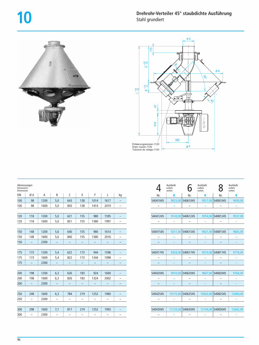
10 Drehrohr-Verteiler 45° staubdichte AusführungStahl grundiert
96
F
410
B
A
110
380
67
L+3
5-3
5 E+1
0-1
0C
+20
-20
45
d
Entleerungsstutzen 120Drain nozzle 120Tubulure de vidage 120
45°
Ausläufe Ausläufe Ausläufeoutlets outlets outlets4 sorties 6 sorties 8 sorties
54041045 9023,00
– –
54041245 9143,00
– –
54041545 9211,00
– –
– –
54041745 9354,00
– –
– –
54042045 9510,00
– –
– –
54042545 10175,00
– –
54043045 11133,00
– –
54061045 9317,00
– –
54061245 9354,00
– –
54061545 9421,00
– –
– –
54061745 9510,00
– –
– –
54062045 9607,00
– –
– –
54062545 10563,00
– –
54063045 12104,00
– –
54081045 9430,00
– –
54081245 9537,00
– –
54081545 9665,00
– –
– –
54081745 9718,00
– –
– –
54082045 9764,00
– –
– –
54082545 12004,00
– –
54083045 12642,00
– –
Nr. € Nr. € Nr. €
100 98 1200 5,0 643 138 1014 1617 –
100 98 1600 5,0 843 138 1414 2019 –
120 118 1200 5,0 621 155 980 1595 –
120 118 1600 5,0 821 155 1380 1997 –
150 148 1200 5,6 640 155 980 1614 –
150 148 1600 5,6 840 155 1380 2016 –
150 – 2300 – – – – – –
175 173 1200 5,4 622 173 944 1596 –
175 173 1600 5,4 822 173 1344 1998 –
175 – 2300 – – – – – –
200 198 1200 6,3 626 183 924 1600 –
200 198 1600 6,3 826 183 1324 2002 –
200 – 2300 – – – – – –
250 248 1600 6,3 784 219 1252 1960 –
250 – 2300 – – – – – –
300 298 1600 7,1 817 219 1252 1993 –
300 – 2300 – – – – – –
AbmessungenDimensionsDimensions
DN Ø d A B C E F L kg
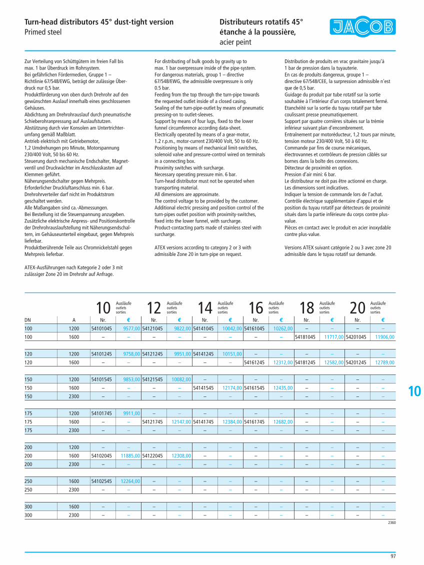
10
Turn-head distributors 45° dust-tight versionPrimed steel
Distributeurs rotatifs 45°étanche á la poussière, acier peint
97
Zur Verteilung von Schüttgütern im freien Fall bis max. 1 bar Überdruck im Rohrsystem.Bei gefährlichen Fördermedien, Gruppe 1 – Richtlinie 67/548/EWG, beträgt der zulässige Über-druck nur 0,5 bar.Produktförderung von oben durch Drehrohr auf dengewünschten Auslauf innerhalb eines geschlossenenGehäuses.Abdichtung am Drehrohrauslauf durch pneumatischeSchieberohranpressung auf Auslaufstutzen.Abstützung durch vier Konsolen am Untertrichter-umfang gemäß Maßblatt.Antrieb elektrisch mit Getriebemotor, 1,2 Umdrehungen pro Minute, Motorspannung230/400 Volt, 50 bis 60 Hz.Steuerung durch mechanische Endschalter, Magnet-ventil und Druckwächter im Anschlusskasten aufKlemmen geführt.Näherungsendschalter gegen Mehrpreis.Erforderlicher Druckluftanschluss min. 6 bar.Drehrohrverteiler darf nicht im Produktstromgeschaltet werden.Alle Maßangaben sind ca.-Abmessungen.Bei Bestellung ist die Steuerspannung anzugeben.Zusätzliche elektrische Anpress- und Positionskontrolleder Drehrohrauslaufstellung mit Näherungsendschal-tern, im Gehäuseunterteil eingebaut, gegen Mehrpreislieferbar.Produktberührende Teile aus Chromnickelstahl gegenMehrpreis lieferbar.
ATEX-Ausführungen nach Kategorie 2 oder 3 mitzulässiger Zone 20 im Drehrohr auf Anfrage.
For distributing of bulk goods by gravity up to max. 1 bar overpressure inside of the pipe-system.For dangerous materials, group 1 – directive67/548/EWG, the admissible overpressure is only 0.5 bar.Feeding from the top through the turn-pipe towardsthe requested outlet inside of a closed casing.Sealing of the turn-pipe-outlet by means of pneumaticpressing-on to outlet-sleeves.Support by means of four lugs, fixed to the lowerfunnel circumference according data-sheet.Electrically operated by means of a gear-motor,1.2 r.p.m., motor-current 230/400 Volt, 50 to 60 Hz.Positioning by means of mechanical limit-switches,solenoid valve and pressure-control wired on terminalsin a connecting box. Proximity switches with surcharge.Necessary operating pressure min. 6 bar.Turn-head distributor must not be operated whentransporting material.All dimensions are approximate.The control voltage to be provided by the customer.Additional electric pressing and position control of theturn-pipes outlet position with proximity-switches,fixed into the lower funnel, with surcharge.Product-contacting parts made of stainless steel withsurcharge.
ATEX versions according to category 2 or 3 withadmissible Zone 20 in turn-pipe on request.
Distribution de produits en vrac gravitaire jusqu’à 1 bar de pression dans la tuyauterie.En cas de produits dangereux, groupe 1 –directive 67/548/CEE, la surpression admissible n'estque de 0,5 bar.Guidage du produit par tube rotatif sur la sortiesouhaitée à l’intérieur d’un corps totalement fermé.Etanchéité sur la sortie du tuyau rotatif par tubecoulissant presse pneumatiquement.Support par quatre cornières situées sur la trémieinférieur suivant plan d’encombrement.Entraînement par motoréducteur, 1,2 tours par minute,tension moteur 230/400 Volt, 50 à 60 Hz.Commande par fins de course mécaniques,électrovannes et contrôleurs de pression câblés surbornes dans la boîte des connexions.Détecteur de proximité en option.Pression d’air mini: 6 bar.Le distributeur ne doit pas être actionné en charge.Les dimensions sont indicatives.Indiquer la tension de commande lors de l’achat.Contrôle électrique supplémentaire d’appui et deposition du tuyau rotatif par détecteurs de proximitésitués dans la partie inférieure du corps contre plus-value.Pièces en contact avec le produit en acier inoxydablecontre plus-value.
Versions ATEX suivant catégorie 2 ou 3 avec zone 20admissible dans le tuyau rotatif sur demande.
Ausläufe Ausläufe Ausläufe Ausläufe Ausläufe Ausläufeoutlets outlets outlets outlets outlets outlets10 sorties 12 sorties 14 sorties 16 sorties 18 sorties 20 sorties
54141045 10042,00
– –
54141245 10151,00
– –
– –
54141545 12174,00
– –
– –
54141745 12384,00
– –
– –
– –
– –
– –
– –
– –
– –
54161045 10262,00
– –
– –
54161245 12312,00
– –
54161545 12435,00
– –
– –
54161745 12682,00
– –
– –
– –
– –
– –
– –
– –
– –
– –
54181045 11717,00
– –
54181245 12582,00
– –
– –
– –
– –
– –
– –
– –
– –
– –
– –
– –
– –
– –
– –
54201045 11906,00
– –
54201245 12789,00
– –
– –
– –
– –
– –
– –
– –
– –
– –
– –
– –
– –
– –
54121045 9822,00
– –
54121245 9951,00
– –
54121545 10082,00
– –
– –
– –
54121745 12147,00
– –
– –
54122045 12308,00
– –
– –
– –
– –
– –
54101045 9577,00
– –
54101245 9758,00
– –
54101545 9853,00
– –
– –
54101745 9911,00
– –
– –
– –
54102045 11885,00
– –
54102545 12264,00
– –
– –
– –
Nr. € Nr. € Nr. € Nr. € Nr. € Nr. €DN A
2360
100 1200
100 1600
120 1200
120 1600
150 1200
150 1600
150 2300
175 1200
175 1600
175 2300
200 1200
200 1600
200 2300
250 1600
250 2300
300 1600
300 2300
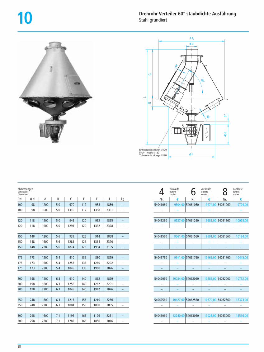
10 Drehrohr-Verteiler 60° staubdichte AusführungStahl grundiert
98
Entleerungsstutzen 120Drain nozzle 120Tubulure de vidage 120 F
450
L
EC
B
A
d
6745
60°
Ausläufe Ausläufe Ausläufeoutlets outlets outlets4 sorties 6 sorties 8 sorties
54041060 9304,00
– –
54041260 9537,00
– –
54041560 9561,00
– –
– –
54041760 9911,00
– –
– –
54042060 10034,00
– –
– –
54042560 10427,00
– –
54043060 12240,00
– –
54061060 9474,00
– –
54061260 9681,00
– –
54061560 9691,00
– –
– –
54061760 10165,00
– –
– –
54062060 10285,00
– –
– –
54062560 10670,00
– –
54063060 13028,00
– –
54081060 9704,00
– –
54081260 10078,00
– –
54081560 10184,00
– –
– –
54081760 10445,00
– –
– –
54082060 10712,00
– –
– –
54082560 12323,00
– –
54083060 13516,00
– –
Nr. € Nr. € Nr. €
100 98 1200 5,0 970 112 958 1889 –
100 98 1600 5,0 1316 112 1358 2351 –
120 118 1200 5,0 946 120 932 1865 –
120 118 1600 5,0 1293 120 1332 2328 –
150 148 1200 5,6 939 125 914 1858 –
150 148 1600 5,6 1285 125 1314 2320 –
150 148 2280 5,6 1874 125 1994 3105 –
175 173 1200 5,4 910 135 880 1829 –
175 173 1600 5,4 1257 135 1280 2292 –
175 173 2280 5,4 1845 135 1960 3076 –
200 198 1200 6,3 910 140 862 1829 –
200 198 1600 6,3 1256 140 1262 2291 –
200 198 2280 6,3 1845 140 1942 3076 –
250 248 1600 6,3 1215 155 1210 2250 –
250 248 2280 6,3 1804 155 1890 3035 –
300 298 1600 7,1 1196 165 1176 2231 –
300 298 2280 7,1 1785 165 1856 3016 –
AbmessungenDimensionsDimensions
DN Ø d A B C E F L kg
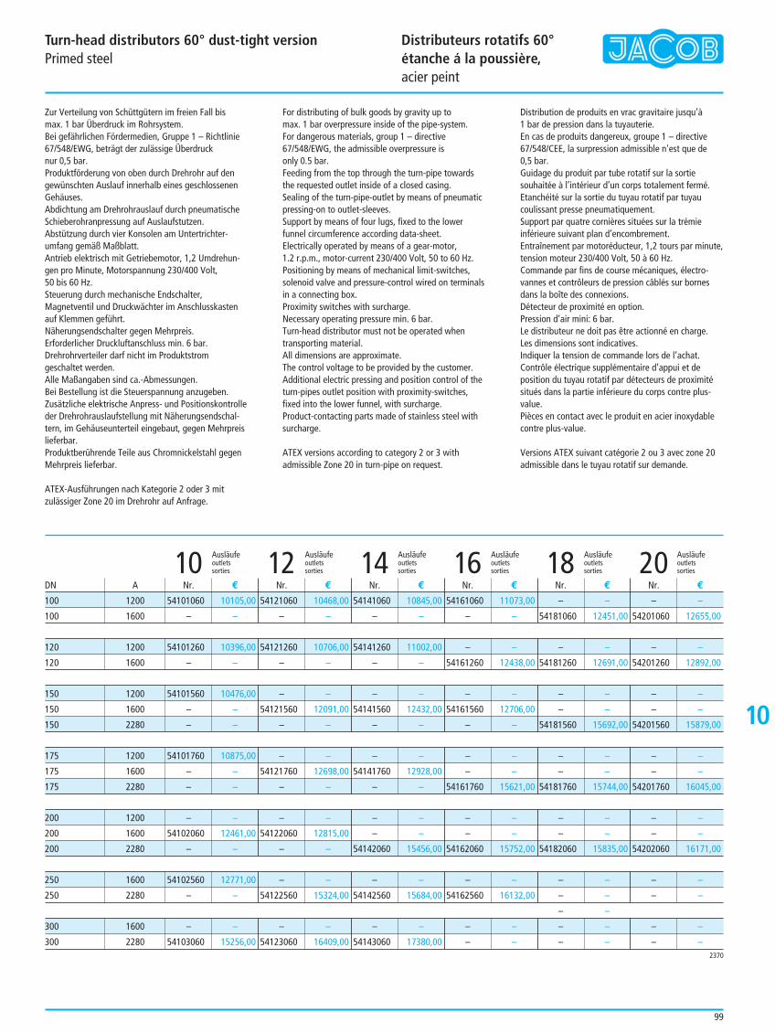
10
Turn-head distributors 60° dust-tight versionPrimed steel
Distributeurs rotatifs 60°étanche á la poussière, acier peint
99
Zur Verteilung von Schüttgütern im freien Fall bis max. 1 bar Überdruck im Rohrsystem.Bei gefährlichen Fördermedien, Gruppe 1 – Richtlinie67/548/EWG, beträgt der zulässige Überdruck nur 0,5 bar.Produktförderung von oben durch Drehrohr auf dengewünschten Auslauf innerhalb eines geschlossenenGehäuses.Abdichtung am Drehrohrauslauf durch pneumatischeSchieberohranpressung auf Auslaufstutzen.Abstützung durch vier Konsolen am Untertrichter-umfang gemäß Maßblatt.Antrieb elektrisch mit Getriebemotor, 1,2 Umdrehun-gen pro Minute, Motorspannung 230/400 Volt,50 bis 60 Hz.Steuerung durch mechanische Endschalter,Magnetventil und Druckwächter im Anschlusskastenauf Klemmen geführt.Näherungsendschalter gegen Mehrpreis.Erforderlicher Druckluftanschluss min. 6 bar.Drehrohrverteiler darf nicht im Produktstromgeschaltet werden.Alle Maßangaben sind ca.-Abmessungen.Bei Bestellung ist die Steuerspannung anzugeben.Zusätzliche elektrische Anpress- und Positionskontrolleder Drehrohrauslaufstellung mit Näherungsendschal-tern, im Gehäuseunterteil eingebaut, gegen Mehrpreislieferbar.Produktberührende Teile aus Chromnickelstahl gegenMehrpreis lieferbar.
ATEX-Ausführungen nach Kategorie 2 oder 3 mitzulässiger Zone 20 im Drehrohr auf Anfrage.
For distributing of bulk goods by gravity up to max. 1 bar overpressure inside of the pipe-system.For dangerous materials, group 1 – directive67/548/EWG, the admissible overpressure is only 0.5 bar.Feeding from the top through the turn-pipe towardsthe requested outlet inside of a closed casing.Sealing of the turn-pipe-outlet by means of pneumaticpressing-on to outlet-sleeves.Support by means of four lugs, fixed to the lowerfunnel circumference according data-sheet.Electrically operated by means of a gear-motor, 1.2 r.p.m., motor-current 230/400 Volt, 50 to 60 Hz.Positioning by means of mechanical limit-switches,solenoid valve and pressure-control wired on terminalsin a connecting box.Proximity switches with surcharge.Necessary operating pressure min. 6 bar.Turn-head distributor must not be operated whentransporting material.All dimensions are approximate.The control voltage to be provided by the customer.Additional electric pressing and position control of theturn-pipes outlet position with proximity-switches,fixed into the lower funnel, with surcharge.Product-contacting parts made of stainless steel withsurcharge.
ATEX versions according to category 2 or 3 withadmissible Zone 20 in turn-pipe on request.
Distribution de produits en vrac gravitaire jusqu’à 1 bar de pression dans la tuyauterie.En cas de produits dangereux, groupe 1 – directive67/548/CEE, la surpression admissible n'est que de 0,5 bar.Guidage du produit par tube rotatif sur la sortiesouhaitée à l’intérieur d’un corps totalement fermé.Etanchéité sur la sortie du tuyau rotatif par tuyaucoulissant presse pneumatiquement.Support par quatre cornières situées sur la trémieinférieure suivant plan d’encombrement.Entraînement par motoréducteur, 1,2 tours par minute,tension moteur 230/400 Volt, 50 à 60 Hz.Commande par fins de course mécaniques, électro-vannes et contrôleurs de pression câblés sur bornesdans la boîte des connexions.Détecteur de proximité en option.Pression d’air mini: 6 bar.Le distributeur ne doit pas être actionné en charge.Les dimensions sont indicatives.Indiquer la tension de commande lors de l’achat.Contrôle électrique supplémentaire d’appui et deposition du tuyau rotatif par détecteurs de proximitésitués dans la partie inférieure du corps contre plus-value.Pièces en contact avec le produit en acier inoxydablecontre plus-value.
Versions ATEX suivant catégorie 2 ou 3 avec zone 20admissible dans le tuyau rotatif sur demande.
Ausläufe Ausläufe Ausläufe Ausläufe Ausläufe Ausläufeoutlets outlets outlets outlets outlets outlets10 sorties 12 sorties 14 sorties 16 sorties 18 sorties 20 sorties
54141060 10845,00
– –
54141260 11002,00
– –
– –
54141560 12432,00
– –
– –
54141760 12928,00
– –
– –
– –
54142060 15456,00
– –
54142560 15684,00
– –
54143060 17380,00
54161060 11073,00
– –
– –
54161260 12438,00
– –
54161560 12706,00
– –
– –
– –
54161760 15621,00
– –
– –
54162060 15752,00
– –
54162560 16132,00
– –
– –
– –
54181060 12451,00
– –
54181260 12691,00
– –
– –
54181560 15692,00
– –
– –
54181760 15744,00
– –
– –
54182060 15835,00
– –
– –
– –
– –
– –
– –
54201060 12655,00
– –
54201260 12892,00
– –
– –
54201560 15879,00
– –
– –
54201760 16045,00
– –
– –
54202060 16171,00
– –
– –
– –
– –
54121060 10468,00
– –
54121260 10706,00
– –
– –
54121560 12091,00
– –
– –
54121760 12698,00
– –
– –
54122060 12815,00
– –
– –
54122560 15324,00
– –
54123060 16409,00
54101060 10105,00
– –
54101260 10396,00
– –
54101560 10476,00
– –
– –
54101760 10875,00
– –
– –
– –
54102060 12461,00
– –
54102560 12771,00
– –
– –
54103060 15256,00
Nr. € Nr. € Nr. € Nr. € Nr. € Nr. €DN A
2370
100 1200
100 1600
120 1200
120 1600
150 1200
150 1600
150 2280
175 1200
175 1600
175 2280
200 1200
200 1600
200 2280
250 1600
250 2280
300 1600
300 2280
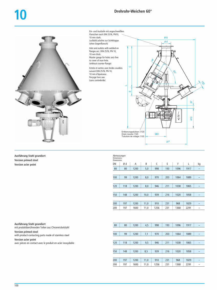
10 Drehrohr-Weichen 60°
100
F
410
60°
LE
C
B
Ad
150
380
67
Entleerungsstutzen 120Drain nozzle 120Tubulure de vidage 120
80 80 1200 5,0 998 193 1096 1917 –
100 99 1200 8,0 970 203 1064 1889 –
120 118 1200 8,0 946 211 1038 1865 –
150 148 1200 10,0 939 216 1020 1858 –
200 197 1200 11,0 910 231 968 1829 –
200 197 1600 11,0 1256 231 1368 2291 –
80 80 1200 4,5 998 193 1096 1917 –
100 99 1200 7,1 970 203 1064 1889 –
120 118 1200 9,5 946 211 1038 1865 –
150 148 1200 8,5 939 216 1020 1858 –
200 197 1200 11,0 910 231 968 1829 –
200 197 1600 11,0 1256 231 1368 2291 –
AbmessungenDimensionsDimensions
DN Ø d A B C E F L kg
Ein- und Ausläufe mit angeschweißten Flanschen nach DIN 2576, PN10, 10 mm stark.Lochbild achsfrei zur Sichtklappe.(ohne Gegenflansch)
Inlet and outlets with welded-on flanges acc. DIN 2576, PN 10, 10 mm thick.Master gauge for holes axis-free to cover of man-hole. (without counter-flange)
Entrée et sorties avec brides soudées suivant DIN 2576, PN 10, 10 mm d’épaisseur.Perçage hors axe.(sans contrebride)
Ausführung Stahl grundiert
Version primed steel
Version acier peint
Ausführung Stahl grundiertmit produktberührenden Teilen aus Chromnickelstahl
Version primed steelwith product-contacting parts made of stainless steel
Version acier peintavec pièces en contact avec le produit en acier inoxydable
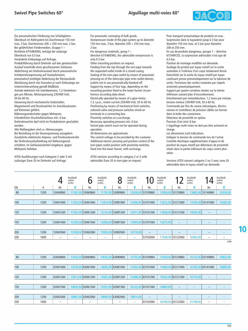
10
Swivel Pipe Switches 60° Aiguillage multi-voies 60°
101
Zur pneumatischen Förderung von Schüttgütern.Überdruck im Rohrsystem bis Durchmesser 150 mmmax. 3 bar, Durchmesser 200 + 250 mm max. 2 bar. Bei gefährlichen Fördermedien, Gruppe 1 – Richtlinie 67/548/EWG, beträgt der zulässigeÜberdruck nur 0,5 bar.Veränderte Einbaulage auf Anfrage.Produktführung durch Drehrohr auf den gewünschtenAuslauf innerhalb eines geschlossenen Gehäuses.Abdichtung am Drehrohrauslauf durch pneumatischeSchieberohranpressung auf Auslaufstutzen,pneumatisch betätigte Abdeckung der Restausläufe.Abstützung durch vier Konsolen je nach Einbaulage amUntertrichterumfang gemäß Maßblatt.Antrieb elektrisch mit Getriebemotor, 1,2 Umdrehun-gen pro Minute, Motorspannung 230/400 Volt,50 bis 60 Hz.Steuerung durch mechanische Endschalter,Magnetventil und Druckwächter im Anschlusskastenauf Klemmen geführt.Näherungsendschalter gegen Mehrpreis.Erforderlicher Druckluftanschluss min. 6 bar.Drehrohrweiche darf nicht im Produktstrom geschaltetwerden.Alle Maßangaben sind ca.-Abmessungen.Bei Bestellung ist die Steuerspannung anzugeben.Zusätzliche elektrische Anpress- und Positionskontrolleder Drehrohrauslaufstellung mit Näherungsend-schaltern, im Gehäuseunterteil eingebaut, gegenMehrpreis lieferbar.
ATEX-Ausführungen nach Kategorie 2 oder 3 mitzulässiger Zone 20 im Drehrohr auf Anfrage.
For pneumatic conveying of bulk goods. Overpressure inside of the pipe-system up to diameter150 mm max. 3 bar, diameter 200 + 250 mm max. 2 bar.For dangerous materials, group 1 – directive 67/548/EWG, the admissible overpressure isonly 0.5 bar.Other mounting positions on request.Feeding from the top through the turn-pipe towardsthe requested outlet inside of a closed casing.Sealing of the turn-pipe-outlet by means of pneumaticpressing-on of the telescopic-pipe onto outlet-sleeves,outlets not in use pneumatically blanked off.Support by means of four lugs, depending on themounting-position fixed to the lower funnel circum-ference according data-sheet.Electrically operated by means of a gear-motor,1.2 r.p.m., motor-current 230/400 Volt, 50 to 60 Hz.Positioning by means of mechanical limit-switches,solenoid valve and pressure switches wired onterminals in a connecting box.Proximity switches at a surcharge.Necessary operating pressure min. 6 bar.Swivel pipe switch must not be operated duringoperation.All dimensions are approximate.The control voltage to be provided by the customer.Additional electric pressing and position control of theturn-pipes outlet position with proximity-switches,fixed into the lower funnel, with surcharge.
ATEX versions according to category 2 or 3 withadmissible Zone 20 in turn-pipe on request.
Pour transport pneumatique de produits en vrac.Surpression dans la tuyauterie jusqu’à 3 bar pourdiamètre 150 mm max. et 2 bar pour diamètre 200 et 250 mm. En cas de produits dangereux, groupe 1 – directive67/548/CEE, la surpression admissible n'est que de 0,5 bar.Position de montage modifiée sur demande.Guidage du produit par tuyau rotatif sur la sortiesouhaitée à l’intérieur d’un corps totalement fermé.Etanchéité sur la sortie du tuyau rotatif par tuyaucoulissant presse pneumatiquement sur la tubulure desortie. Fermeture des sorties restantes par clapetsactionnés pneumatiquement.Support par quatre cornières situées sur la trémieinférieure suivant plan d’encombrement.Entraînement par motoréducteur, 1,2 tours par minute,tension moteur 230/400 Volt, 50 à 60 Hz.Commande par fins de course mécaniques, électro-vannes et contrôleurs de pression câblés sur bornesdans la boîte des connexions.Détecteur de proximité en option.Pression d’air mini: 6 bar.L’aiguillage multi-voies ne doit pas être actionné encharge.Les dimensions sont indicatives.Indiquer la tension de commande lors de l’achat.Contrôle électrique supplémentaire d’appui et deposition du tuyau rotatif par détecteurs de proximitésitués dans la partie inférieure du corps contre plus-value.
Versions ATEX suivant catégorie 2 ou 3 avec zone 20admissible dans le tuyau rotatif sur demande.
Ausläufe Ausläufe Ausläufe Ausläufe Ausläufe Ausläufeoutlets outlets outlets outlets outlets outlets4 sorties 6 sorties 8 sorties 10 sorties 12 sorties 14 sorties
53080860 12428,00
53081060 12456,00
53081260 12911,00
53081560 13584,00
53082060 16718,00
– –
63080860 14732,00
63081060 14764,00
63081260 15288,00
63081560 16122,00
63082060 19814,00
– –
53100860 13058,00
53101060 13212,00
53101260 13568,00
53101560 14275,00
– –
53102060 17528,00
63100860 15428,00
63101060 15469,00
63101260 16032,00
63101560 16883,00
– –
63102060 20708,00
53120860 13685,00
53121060 13740,00
53121260 14245,00
– –
– –
53122060 18363,00
63120860 16132,00
63121060 16185,00
63121260 16774,00
– –
– –
63122060 21708,00
53140860 14316,00
53141060 14383,00
– –
– –
– –
– –
63140860 16822,00
63141060 16889,00
– –
– –
– –
– –
53060860 11791,00
53061060 11819,00
53061260 12216,00
53061560 12856,00
53062060 15920,00
– –
63060860 14032,00
63061060 14056,00
63061260 14561,00
63061560 15351,00
63062060 18944,00
– –
53040860 11181,00
53041060 11202,00
53041260 11562,00
53041560 12193,00
53042060 15108,00
– –
63040860 13332,00
63041060 13378,00
63041260 13815,00
63041560 14654,00
63042060 18061,00
– –
Nr. € Nr. € Nr. € Nr. € Nr. € Nr. €DN A
2380
80 1200
100 1200
120 1200
150 1200
200 1200
200 1600
80 1200
100 1200
120 1200
150 1200
200 1200
200 1600
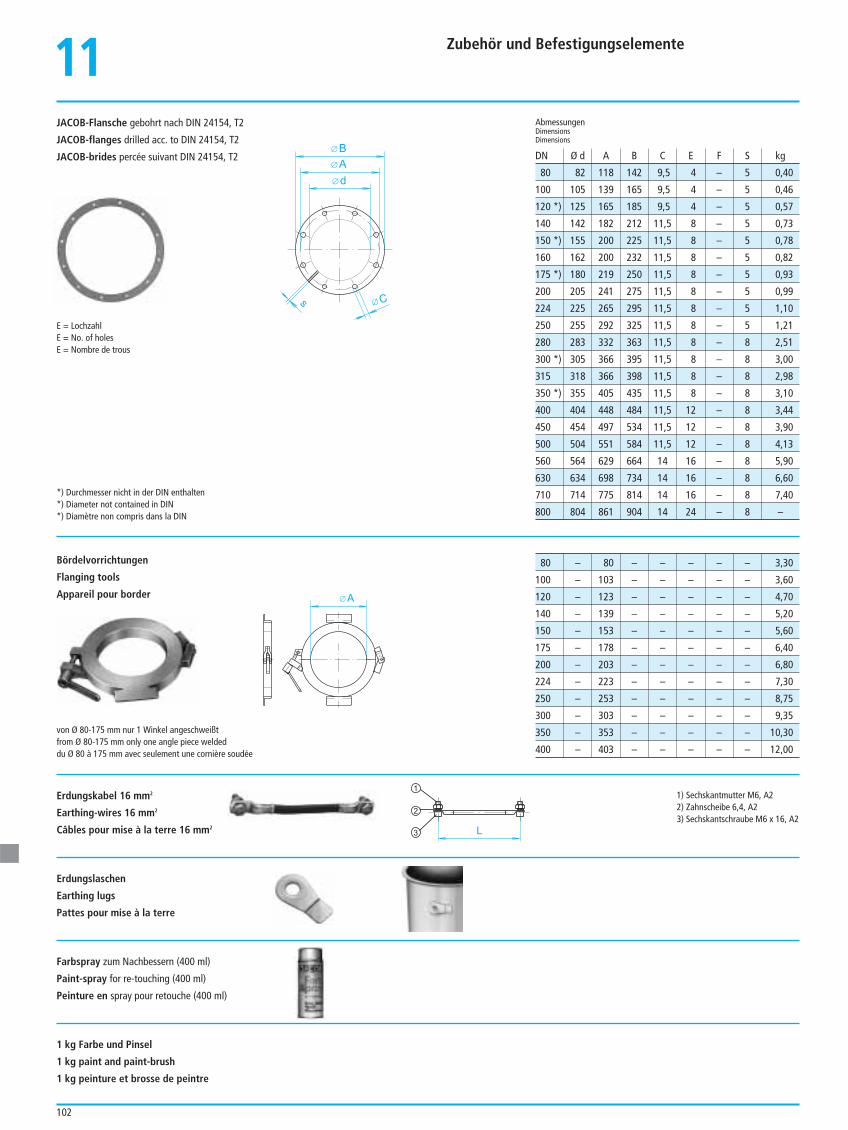
Zubehör und Befestigungselemente
102
JACOB-Flansche gebohrt nach DIN 24154, T2
JACOB-flanges drilled acc. to DIN 24154, T2
JACOB-brides percée suivant DIN 24154, T2
11
80 82 118 142 9,5 4 – 5 0,40
100 105 139 165 9,5 4 – 5 0,46
120 *) 125 165 185 9,5 4 – 5 0,57
140 142 182 212 11,5 8 – 5 0,73
150 *) 155 200 225 11,5 8 – 5 0,78
160 162 200 232 11,5 8 – 5 0,82
175 *) 180 219 250 11,5 8 – 5 0,93
200 205 241 275 11,5 8 – 5 0,99
224 225 265 295 11,5 8 – 5 1,10
250 255 292 325 11,5 8 – 5 1,21
280 283 332 363 11,5 8 – 8 2,51
300 *) 305 366 395 11,5 8 – 8 3,00
315 318 366 398 11,5 8 – 8 2,98
350 *) 355 405 435 11,5 8 – 8 3,10
400 404 448 484 11,5 12 – 8 3,44
450 454 497 534 11,5 12 – 8 3,90
500 504 551 584 11,5 12 – 8 4,13
560 564 629 664 14 16 – 8 5,90
630 634 698 734 14 16 – 8 6,60
710 714 775 814 14 16 – 8 7,40
800 804 861 904 14 24 – 8 –
AbmessungenDimensionsDimensions
DN Ø d A B C E F S kg
d
C
A
B
s
E = LochzahlE = No. of holesE = Nombre de trous
Bördelvorrichtungen
Flanging tools
Appareil pour borderA
L
1
2
3
von Ø 80-175 mm nur 1 Winkel angeschweißtfrom Ø 80-175 mm only one angle piece weldeddu Ø 80 à 175 mm avec seulement une cornière soudée
*) Durchmesser nicht in der DIN enthalten*) Diameter not contained in DIN*) Diamètre non compris dans la DIN
80 – 80 – – – – – 3,30
100 – 103 – – – – – 3,60
120 – 123 – – – – – 4,70
140 – 139 – – – – – 5,20
150 – 153 – – – – – 5,60
175 – 178 – – – – – 6,40
200 – 203 – – – – – 6,80
224 – 223 – – – – – 7,30
250 – 253 – – – – – 8,75
300 – 303 – – – – – 9,35
350 – 353 – – – – – 10,30
400 – 403 – – – – – 12,00
1) Sechskantmutter M6, A22) Zahnscheibe 6,4, A23) Sechskantschraube M6 x 16, A2
Erdungskabel 16 mm2
Earthing-wires 16 mm2
Câbles pour mise à la terre 16 mm2
Erdungslaschen
Earthing lugs
Pattes pour mise à la terre
Farbspray zum Nachbessern (400 ml)
Paint-spray for re-touching (400 ml)
Peinture en spray pour retouche (400 ml)
1 kg Farbe und Pinsel
1 kg paint and paint-brush
1 kg peinture et brosse de peintre
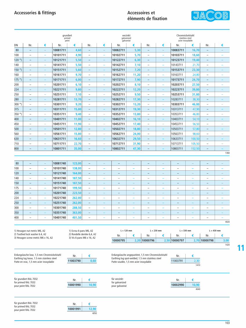
Accessories & fittings Accessoires et éléments de fixation
103
11
grundiert verzinkt Chromnickelstahlprimed galvanized stainless steelpeint galvanisé acier inoxydable
– –
– –
– –
– –
– –
– –
– –
– –
– –
– –
– –
– –
– –
– –
– –
– –
– –
– –
– –
– –
– –
10081711 4,60
10101711 4,90
10121711 5,50
10141711 5,50
10151711 5,60
10161711 9,70
10171711 6,00
10201711 6,10
10221711 9,80
10251711 7,10
10281711 13,70
10301711 9,20
10311711 15,00
10351711 9,40
10401711 11,00
10451711 11,90
10501711 12,80
10561711 15,80
10631711 16,60
10711711 22,70
10801711 35,00
– –
– –
– –
– –
– –
– –
– –
– –
– –
– –
– –
– –
– –
– –
– –
– –
– –
– –
– –
– –
– –
10082711 5,30
10102711 5,70
10122711 6,30
10142711 7,10
10152711 7,20
10162711 11,20
10172711 7,90
10202711 8,10
10222711 12,20
10252711 9,50
10282711 17,30
10302711 13,20
10312711 19,30
10352711 13,80
10402711 16,10
10452711 17,40
10502711 18,80
10562711 24,00
10632711 29,50
10712711 31,90
10802711 47,30
– –
– –
– –
– –
– –
– –
– –
– –
– –
– –
– –
– –
– –
– –
– –
– –
– –
– –
– –
– –
– –
10083711 16,70
10103711 18,60
10123711 19,40
10143711 21,70
10153711 23,30
10163711 24,80
10173711 24,70
10203711 27,50
10223711 39,80
10253711 31,80
10283711 38,30
10303711 46,00
10313711 47,90
10353711 46,80
10403711 54,10
10453711 56,50
10503711 57,80
10563711 98,60
10633711 100,50
10713711 105,50
10803711 152,50
– –
– –
– –
– –
– –
– –
– –
– –
– –
– –
– –
– –
– –
– –
– –
– –
– –
– –
– –
– –
– –
Nr. € Nr. € Nr. € Nr. € Nr. € Nr. € Nr. €DN
1360
4020
1420
1410
80
100
120 *)
140
150 *)
160
175 *)
200
224
250
280
300 *)
315
350 *)
400
450
500
560
630
710
800
L = 120 mm L = 230 mm L = 330 mm L = 430 mm
10000795 2,20 10000796 2,50 10000797 2,70 10000798 3,00
Nr. € Nr. € Nr. € Nr. €
11003791 2,30
Nr. €
11003790 0,60
Nr. €
4040
4050
10002990 10,90
Nr. €
10001990 10,90
Nr. €
10001991 12,90
Nr. €
2060
– –
– –
– –
– –
– –
– –
– –
– –
– –
– –
– –
– –
10081740 123,00
10101740 138,00
10121740 164,00
10141740 187,50
10151740 187,50
10171740 199,50
10201740 223,50
10221740 262,00
10251740 262,00
10301740 288,50
10351740 363,00
10401740 401,50
– –
– –
– –
– –
– –
– –
– –
– –
– –
– –
– –
– –
– –
– –
– –
– –
– –
– –
– –
– –
– –
– –
– –
– –
– –
– –
– –
– –
– –
– –
– –
– –
– –
– –
– –
– –
– –
– –
– –
– –
– –
– –
– –
– –
– –
– –
– –
– –
– –
– –
– –
– –
– –
– –
– –
– –
– –
– –
– –
– –
80
100
120
140
150
175
200
224
250
300
350
400
Erdungslasche lose, 1,5 mm ChromnickelstahlEarthing lug loose, 1.5 mm stainless steelPatte en vrac, 1,5 mm acier inoxydable
für grundiert RAL 7032for primed RAL 7032pour peint RAL 7032
1) Hexagon nut metric M6, A22) Toothed lock washer 6.4, A23) Hexagon screw metric M6 x 16, A2
Erdungslasche angepunktet, 1,5 mm ChromnickelstahlEarthing lug spot-welded, 1.5 mm stainless steelPatte soudée, 1,5 mm acier inoxydable
für verzinktfor galvanizedpour galvanisé
für grundiert RAL 7032for primed RAL 7032pour peint RAL 7032
1) Ecrou 6-pans M6, A22) Rondelle dentée 6,4, A23) Vis 6-pans M6 x 16, A2
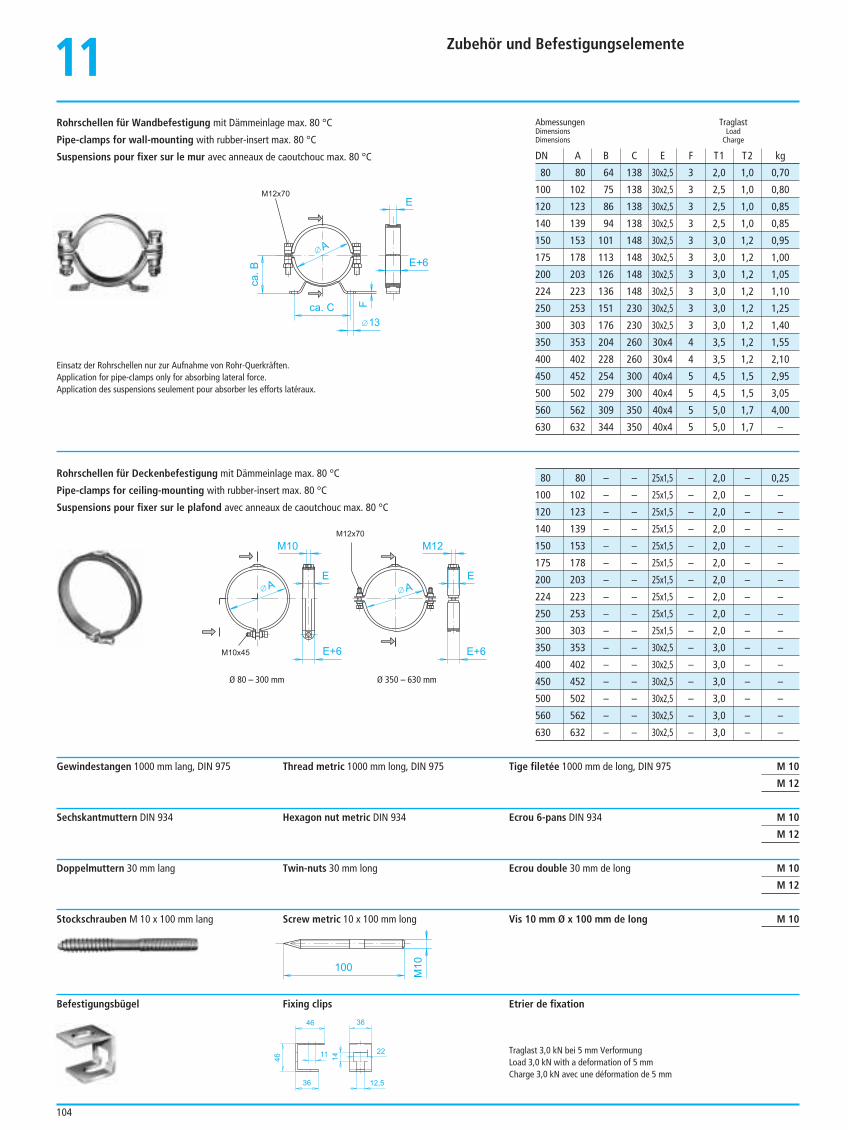
11 Zubehör und Befestigungselemente
104
80 80 64 138 30x2,5 3 2,0 1,0 0,70
100 102 75 138 30x2,5 3 2,5 1,0 0,80
120 123 86 138 30x2,5 3 2,5 1,0 0,85
140 139 94 138 30x2,5 3 2,5 1,0 0,85
150 153 101 148 30x2,5 3 3,0 1,2 0,95
175 178 113 148 30x2,5 3 3,0 1,2 1,00
200 203 126 148 30x2,5 3 3,0 1,2 1,05
224 223 136 148 30x2,5 3 3,0 1,2 1,10
250 253 151 230 30x2,5 3 3,0 1,2 1,25
300 303 176 230 30x2,5 3 3,0 1,2 1,40
350 353 204 260 30x4 4 3,5 1,2 1,55
400 402 228 260 30x4 4 3,5 1,2 2,10
450 452 254 300 40x4 5 4,5 1,5 2,95
500 502 279 300 40x4 5 4,5 1,5 3,05
560 562 309 350 40x4 5 5,0 1,7 4,00
630 632 344 350 40x4 5 5,0 1,7 –
Abmessungen TraglastDimensions LoadDimensions Charge
DN A B C E F T1 T2 kg
A
E
E+6ca.B
ca. C F
13
M12x70
Einsatz der Rohrschellen nur zur Aufnahme von Rohr-Querkräften.Application for pipe-clamps only for absorbing lateral force.Application des suspensions seulement pour absorber les efforts latéraux.
A
E
E+6E+6
E
M12M10
A
M10x45
M12x70
46
46
36
11
12,5
36
14
22
Ø 80 – 300 mm Ø 350 – 630 mm
80 80 – – 25x1,5 – 2,0 – 0,25
100 102 – – 25x1,5 – 2,0 – –
120 123 – – 25x1,5 – 2,0 – –
140 139 – – 25x1,5 – 2,0 – –
150 153 – – 25x1,5 – 2,0 – –
175 178 – – 25x1,5 – 2,0 – –
200 203 – – 25x1,5 – 2,0 – –
224 223 – – 25x1,5 – 2,0 – –
250 253 – – 25x1,5 – 2,0 – –
300 303 – – 25x1,5 – 2,0 – –
350 353 – – 30x2,5 – 3,0 – –
400 402 – – 30x2,5 – 3,0 – –
450 452 – – 30x2,5 – 3,0 – –
500 502 – – 30x2,5 – 3,0 – –
560 562 – – 30x2,5 – 3,0 – –
630 632 – – 30x2,5 – 3,0 – –
Gewindestangen 1000 mm lang, DIN 975 Thread metric 1000 mm long, DIN 975 Tige filetée 1000 mm de long, DIN 975 M 10
M 12
Sechskantmuttern DIN 934 Hexagon nut metric DIN 934 Ecrou 6-pans DIN 934 M 10
M 12
Doppelmuttern 30 mm lang Twin-nuts 30 mm long Ecrou double 30 mm de long M 10
M 12
Stockschrauben M 10 x 100 mm lang Screw metric 10 x 100 mm long Vis 10 mm Ø x 100 mm de long M 10
Befestigungsbügel Fixing clips Etrier de fixation
Traglast 3,0 kN bei 5 mm VerformungLoad 3,0 kN with a deformation of 5 mmCharge 3,0 kN avec une déformation de 5 mm
Rohrschellen für Wandbefestigung mit Dämmeinlage max. 80 °C
Pipe-clamps for wall-mounting with rubber-insert max. 80 °C
Suspensions pour fixer sur le mur avec anneaux de caoutchouc max. 80 °C
Rohrschellen für Deckenbefestigung mit Dämmeinlage max. 80 °C
Pipe-clamps for ceiling-mounting with rubber-insert max. 80 °C
Suspensions pour fixer sur le plafond avec anneaux de caoutchouc max. 80 °C
100
M10
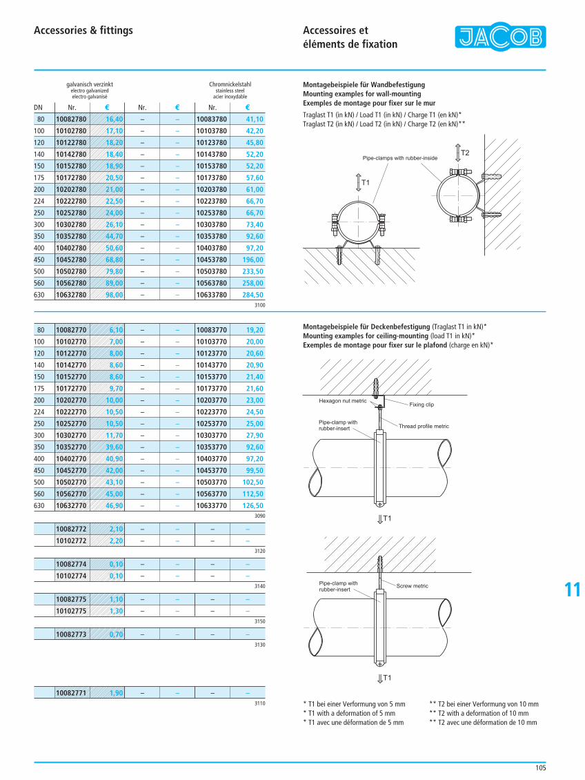
11
Accessories & fittings Accessoires etéléments de fixation
105
galvanisch verzinkt Chromnickelstahlelectro galvanized stainless steelelectro galvanisé acier inoxydable
– –
– –
– –
– –
– –
– –
– –
– –
– –
– –
– –
– –
– –
– –
– –
– –
10083780 41,10
10103780 42,20
10123780 45,80
10143780 52,20
10153780 52,20
10173780 57,60
10203780 61,00
10223780 66,70
10253780 66,70
10303780 73,40
10353780 92,60
10403780 97,20
10453780 196,00
10503780 233,50
10563780 258,00
10633780 284,50
Nr. € Nr. € Nr. €DN
3100
3120
80
100
120
140
150
175
200
224
250
300
350
400
450
500
560
630
– –
– –
– –
– –
– –
– –
– –
– –
– –
– –
– –
– –
– –
– –
– –
– –
10083770 19,20
10103770 20,00
10123770 20,60
10143770 20,90
10153770 21,40
10173770 21,60
10203770 23,00
10223770 24,50
10253770 25,00
10303770 27,90
10353770 92,60
10403770 97,20
10453770 99,50
10503770 102,50
10563770 112,50
10633770 126,503090
80
100
120
140
150
175
200
224
250
300
350
400
450
500
560
630
– –
– –
– –
– –
3140
– –
– –
– –
– –
3150
– –
– –
– –
– –
3130
– – – –
3110
– – – –
Montagebeispiele für Deckenbefestigung (Traglast T1 in kN)*Mounting examples for ceiling-mounting (load T1 in kN)*Exemples de montage pour fixer sur le plafond (charge en kN)*
Hexagon nut metric
Pipe-clamp withrubber-insert Thread profile metric
Fixing clip
T1
Pipe-clamp withrubber-insert
Screw metric
T1
10082780 16,40
10102780 17,10
10122780 18,20
10142780 18,40
10152780 18,90
10172780 20,50
10202780 21,00
10222780 22,50
10252780 24,00
10302780 26,10
10352780 44,70
10402780 50,60
10452780 68,80
10502780 79,80
10562780 89,00
10632780 98,00
10082770 6,10
10102770 7,00
10122770 8,00
10142770 8,60
10152770 8,60
10172770 9,70
10202770 10,00
10222770 10,50
10252770 10,50
10302770 11,70
10352770 39,60
10402770 40,90
10452770 42,00
10502770 43,10
10562770 45,00
10632770 46,90
10082772 2,10
10102772 2,20
10082773 0,70
10082775 1,10
10102775 1,30
10082774 0,10
10102774 0,10
10082771 1,90
T1
T2Pipe-clamps with rubber-inside
Montagebeispiele für WandbefestigungMounting examples for wall-mountingExemples de montage pour fixer sur le mur
Traglast T1 (in kN) / Load T1 (in kN) / Charge T1 (en kN)*Traglast T2 (in kN) / Load T2 (in kN) / Charge T2 (en kN)**
* T1 bei einer Verformung von 5 mm * T1 with a deformation of 5 mm * T1 avec une déformation de 5 mm
** T2 bei einer Verformung von 10 mm ** T2 with a deformation of 10 mm ** T2 avec une déformation de 10 mm
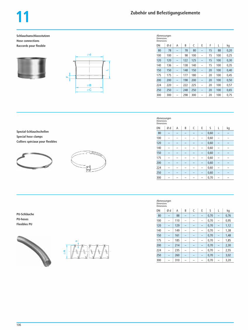
11 Zubehör und Befestigungselemente
106
d
BC
L
FA
s
Schlauchanschlussstutzen
Hose connections
Raccords pour flexible
Spezial-Schlauchschellen
Special hose clamps
Colliers spéciaux pour flexibles
PU-Schläuche
PU-hoses
Flexibles PU
80 78 – 78 80 – 15 88 0,20
100 100 – 98 100 – 15 100 0,25
120 120 – 122 125 – 15 100 0,30
140 136 – 138 140 – 15 100 0,35
150 150 – 148 150 – 20 100 0,40
175 175 – 177 180 – 20 100 0,45
200 200 – 198 200 – 20 100 0,50
224 220 – 222 225 – 20 100 0,57
250 250 – 248 250 – 20 100 0,65
300 300 – 298 300 – 20 100 0,75
AbmessungenDimensionsDimensions
AbmessungenDimensionsDimensions
AbmessungenDimensionsDimensions
DN Ø d A B C E F L kg
DN Ø d A B C E S L kg
DN Ø d A B C E S L kg
80 – – – – – 0,60 – –
100 – – – – – 0,60 – –
120 – – – – – 0,60 – –
140 – – – – – 0,60 – –
150 – – – – – 0,60 – –
175 – – – – – 0,60 – –
200 – – – – – 0,60 – –
224 – – – – – 0,60 – –
250 – – – – – 0,60 – –
300 – – – – – 0,70 – –
80 – 88 – – – 0,70 – 0,76
100 – 110 – – – 0,70 – 0,95
120 – 129 – – – 0,70 – 1,12
140 – 149 – – – 0,70 – 1,38
150 – 161 – – – 0,70 – 1,48
175 – 185 – – – 0,70 – 1,85
200 – 214 – – – 0,70 – 2,30
224 – 235 – – – 0,70 – 2,55
250 – 260 – – – 0,70 – 3,02
300 – 310 – – – 0,70 – 3,20
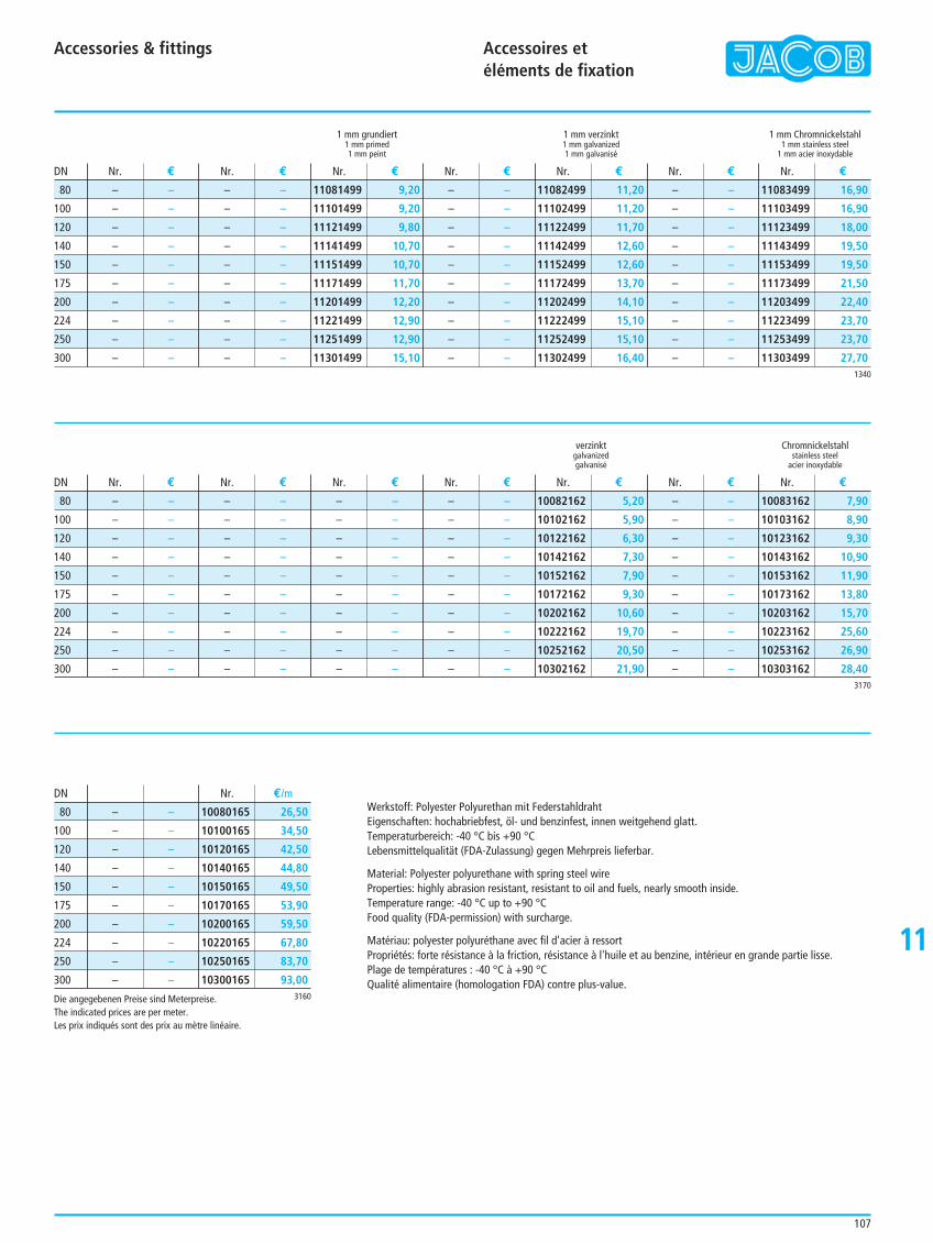
11
Accessories & fittings Accessoires et éléments de fixation
107
1 mm grundiert 1 mm verzinkt 1 mm Chromnickelstahl1 mm primed 1 mm galvanized 1 mm stainless steel1 mm peint 1 mm galvanisé 1 mm acier inoxydable
verzinkt Chromnickelstahlgalvanized stainless steelgalvanisé acier inoxydable
– –
– –
– –
– –
– –
– –
– –
– –
– –
– –
– –
– –
– –
– –
– –
– –
– –
– –
– –
– –
11081499 9,20
11101499 9,20
11121499 9,80
11141499 10,70
11151499 10,70
11171499 11,70
11201499 12,20
11221499 12,90
11251499 12,90
11301499 15,10
– –
– –
– –
– –
– –
– –
– –
– –
– –
– –
11082499 11,20
11102499 11,20
11122499 11,70
11142499 12,60
11152499 12,60
11172499 13,70
11202499 14,10
11222499 15,10
11252499 15,10
11302499 16,40
– –
– –
– –
– –
– –
– –
– –
– –
– –
– –
11083499 16,90
11103499 16,90
11123499 18,00
11143499 19,50
11153499 19,50
11173499 21,50
11203499 22,40
11223499 23,70
11253499 23,70
11303499 27,70
Nr. € Nr. € Nr. € Nr. € Nr. € Nr. € Nr. €
Nr. € Nr. € Nr. € Nr. € Nr. € Nr. € Nr. €
Nr. €/m
DN
DN
DN
1340
80
100
120
140
150
175
200
224
250
300
3170
– –
– –
– –
– –
– –
– –
– –
– –
– –
– –
– –
– –
– –
– –
– –
– –
– –
– –
– –
– –
– –
– –
– –
– –
– –
– –
– –
– –
– –
– –
– –
– –
– –
– –
– –
– –
– –
– –
– –
– –
10082162 5,20
10102162 5,90
10122162 6,30
10142162 7,30
10152162 7,90
10172162 9,30
10202162 10,60
10222162 19,70
10252162 20,50
10302162 21,90
– –
– –
– –
– –
– –
– –
– –
– –
– –
– –
10083162 7,90
10103162 8,90
10123162 9,30
10143162 10,90
10153162 11,90
10173162 13,80
10203162 15,70
10223162 25,60
10253162 26,90
10303162 28,40
80
100
120
140
150
175
200
224
250
300
3160
– –
– –
– –
– –
– –
– –
– –
– –
– –
– –
10080165 26,50
10100165 34,50
10120165 42,50
10140165 44,80
10150165 49,50
10170165 53,90
10200165 59,50
10220165 67,80
10250165 83,70
10300165 93,00
80
100
120
140
150
175
200
224
250
300
Werkstoff: Polyester Polyurethan mit FederstahldrahtEigenschaften: hochabriebfest, öl- und benzinfest, innen weitgehend glatt.Temperaturbereich: -40 °C bis +90 °CLebensmittelqualität (FDA-Zulassung) gegen Mehrpreis lieferbar.
Material: Polyester polyurethane with spring steel wireProperties: highly abrasion resistant, resistant to oil and fuels, nearly smooth inside.Temperature range: -40 °C up to +90 °CFood quality (FDA-permission) with surcharge.
Matériau: polyester polyuréthane avec fil d'acier à ressortPropriétés: forte résistance à la friction, résistance à l'huile et au benzine, intérieur en grande partie lisse.Plage de températures : -40 °C à +90 °CQualité alimentaire (homologation FDA) contre plus-value.
Die angegebenen Preise sind Meterpreise.The indicated prices are per meter.Les prix indiqués sont des prix au mètre linéaire.
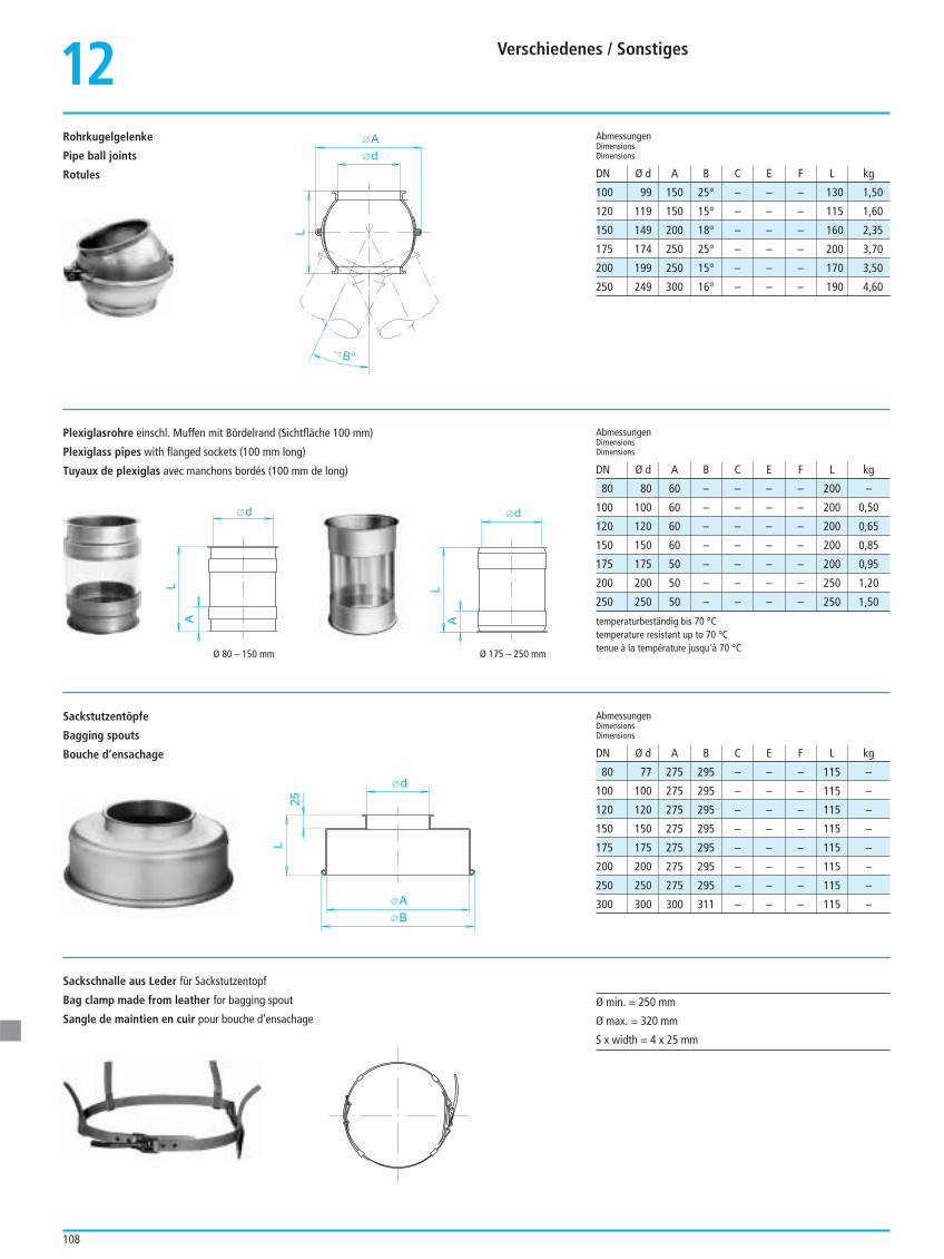
Verschiedenes / Sonstiges
108
Rohrkugelgelenke
Pipe ball joints
Rotules
12
Sackstutzentöpfe
Bagging spouts
Bouche d’ensachage
100 99 150 25° – – – 130 1,50
120 119 150 15° – – – 115 1,60
150 149 200 18° – – – 160 2,35
175 174 250 25° – – – 200 3,70
200 199 250 15° – – – 170 3,50
250 249 300 16° – – – 190 4,60
AbmessungenDimensionsDimensions
DN Ø d A B C E F L kg
AbmessungenDimensionsDimensions
AbmessungenDimensionsDimensions
DN Ø d A B C E F L kg
DN Ø d A B C E F L kg
temperaturbeständig bis 70 °Ctemperature resistant up to 70 °Ctenue à la température jusqu'à 70 °C
d
L
A
A
L
25
B
d
d
A
L
B°
Plexiglasrohre einschl. Muffen mit Bördelrand (Sichtfläche 100 mm)
Plexiglass pipes with flanged sockets (100 mm long)
Tuyaux de plexiglas avec manchons bordés (100 mm de long)
80 80 60 – – – – 200 –
100 100 60 – – – – 200 0,50
120 120 60 – – – – 200 0,65
150 150 60 – – – – 200 0,85
175 175 50 – – – – 200 0,95
200 200 50 – – – – 250 1,20
250 250 50 – – – – 250 1,50
80 77 275 295 – – – 115 –
100 100 275 295 – – – 115 –
120 120 275 295 – – – 115 –
150 150 275 295 – – – 115 –
175 175 275 295 – – – 115 –
200 200 275 295 – – – 115 –
250 250 275 295 – – – 115 –
300 300 300 311 – – – 115 –
Ø min. = 250 mm
Ø max. = 320 mm
S x width = 4 x 25 mm
Ø 175 – 250 mm
L
d
A
Ø 80 – 150 mm
Sackschnalle aus Leder für Sackstutzentopf
Bag clamp made from leather for bagging spout
Sangle de maintien en cuir pour bouche d’ensachage
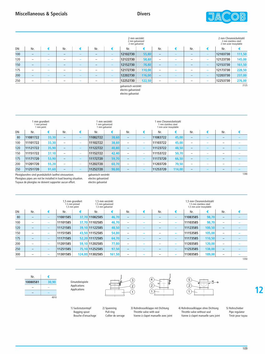
Miscellaneous & Specials Divers
109
12
Plexiglasrohre sind grundsätzlich lastfrei einzusetzen.Plexiglass pipes are not be installed in load bearing situation.Tuyaux de plexiglas ne doivent supporter aucun effort.
2 mm verzinkt 2 mm Chromnickelstahl2 mm galvanized 2 mm stainless steel2 mm galvanisé 2 mm acier inoxydable
1 mm grundiert 1 mm verzinkt 1 mm Chromnickelstahl1 mm primed 1 mm galvanized 1 mm stainless steel1 mm peint 1 mm galvanisé 1 mm acier inoxydable
1,5 mm grundiert 1,5 mm verzinkt 1,5 mm Chromnickelstahl1.5 mm primed 1.5 mm galvanized 1.5 mm stainless steel1,5 mm peint 1,5 mm galvanisé 1,5 mm acier inoxydable
– –
– –
– –
– –
– –
– –
– –
– –
– –
– –
– –
– –
– –
– –
– –
– –
– –
– –
– –
– –
– –
– –
– –
– –
– –
– –
– –
– –
– –
– –
12103730 111,50
12123730 145,00
12153730 161,50
12173730 228,50
12203730 237,00
12253730 276,00
Nr. € Nr. € Nr. € Nr. € Nr. € Nr. € Nr. €
Nr. € Nr. € Nr. € Nr. € Nr. € Nr. € Nr. €
Nr. € Nr. € Nr. € Nr. € Nr. € Nr. € Nr. €
DN
DN
DN
2125
100
120
150
175
200
250
11081722 33,30
11101722 33,30
11121722 35,90
11151722 37,10
11171720 53,90
11201720 55,20
11251720 91,60
– –
– –
– –
– –
– –
– –
– –
– –
– –
– –
– –
– –
– –
– –
11083722 45,00
11103722 45,00
11123722 48,50
11153722 50,70
11173720 66,50
11203720 70,50
11253720 114,00
– –
– –
– –
– –
– –
– –
– –
– –
– –
– –
– –
– –
– –
– –1390
80
100
120
150
175
200
250
– –
– –
– –
– –
– –
– –
– –
– –
11081585 37,70
11101585 37,70
11121585 39,10
11151585 43,50
11171585 52,20
11201585 59,10
11251585 75,10
11301585 124,00
11082585 46,70
11102585 46,70
11122585 48,50
11152585 54,00
11172585 64,70
11202585 77,00
11252585 97,50
11302585 161,50
– –
– –
– –
– –
– –
– –
– –
– –
– –
– –
– –
– –
– –
– –
– –
– –
11083585 98,70
11103585 98,70
11123585 100,50
11153585 105,00
11173585 110,50
11203585 120,00
11253585 138,00
11303585 189,00
– –
– –
– –
– –
– –
– –
– –
– –1350
80
100
120
150
175
200
250
300
galvanisch verzinktelectro galvanizedelectro galvanisé
galvanisch verzinktelectro galvanizedelectro galvanisé
4010
10080581 30,90
– –
– –
Nr. €
EinsatzbeispieleApplicationsApplications
1
2
3 4
1
2
5
1
2
1) SackstutzentopfBagging spoutBouche d’ensachage
2) SpannringPull-ringCollier de serrage
3) Rohrdrosselklappe mit DichtungThrottle valve with sealVanne à clapet manuelle avec joint
4) Rohrdrosselklappe ohne DichtungThrottle valve without sealVanne à clapet manuelle sans joint
5) RohrschieberPipe regulatorTiroir pour tuyau
12102730 55,80
12122730 58,60
12152730 78,80
12172730 110,00
12202730 116,00
12252730 122,50
11082722 38,60
11102722 38,60
11122722 40,80
11152722 42,40
11172720 59,70
11202720 60,70
11252720 98,00
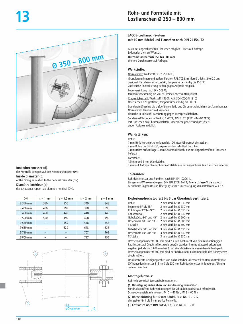
Rohr- und Formteile mitLosflanschen Ø 350 – 800 mm
110
13JACOB-Losflansch-Systemmit 10 mm Bördel und Flanschen nach DIN 24154, T2
Auch mit angeschweißten Flanschen möglich – Preis auf Anfrage.Erdungslaschen auf Wunsch.Durchmesserbereich 350 bis 800 mm.Weitere Durchmesser auf Anfrage.
Werkstoffe:Normalstahl: Werkstoff DC 01 (ST 1203)Grundierung innen und außen, Farbton RAL 7032, mittlere Schichtstärke 20 µm,geeignet für Lebensmittelkontakt, temperaturbeständig bis 150 °C. Zusätzliche Endlackierung außen gegen Aufpreis möglich.Feuerverzinkung nach DIN 50976,temperaturbeständig bis 200 °C, keine Lebensmittelqualität.Chromnickelstahl: Werkstoff 1.4301, AISI 304 (X5CrNi1810)Oberfläche Cr-Ni-gestrahlt, temperaturbeständig bis 300 °C.Standardmäßig sind die aufgeführten Teile aus Chromnickelstahl mit Losflanschen ausNormalstahl feuerverzinkt versehen.Flansche in Edelstahl-Ausführung gegen Mehrpreis lieferbar.Sonderausführungen in Werkst. 1.4571, AISI 316Ti (X6CrNiMoTi17122)mit Flanschen aus Chromnickelstahl, Oberfläche gebeizt und passiviert,gegen Aufpreis möglich.
Wandstärken:Rohre:1 mm für lufttechnische Anlagen bis 100 mbar Überdruck einsetzbar.2 mm Rohre bis DN ≤ 630, explosionsdruckstoßfest bis 3 bar.3 mm Rohre auf Anfrage, 3 mm Chromnickelstahl nur mit angeschweißten Flanschenlieferbar.Formteile:1,5 mm und 2 mm Wandstärke.3 mm auf Anfrage, 3 mm Chromnickelstahl nur mit angeschweißten Flanschen lieferbar.
Toleranzen:Rohrdurchmesser und Rundheit nach DIN EN 10296-1.Längen und Winkelmaße gem. DIN ISO 2768, Teil 1, Toleranzklasse V, sehr grob.Ausnahme: Segmente und Übergangsstücke unter Neigung Winkeltoleranz = ± 1°.
Explosionsdruckstoßfest bis 3 bar Überdruck zertifiziert:Rohre 2 mm stark bis Ø 630 mmSegmente 5° bis 45° 2 mm stark bis Ø 630 mmRohrbogen 30° bis 90° 2 mm stark bis Ø 630 mmKonusstücke 2 mm stark bis Ø 630 mmGabelstücke 30° und 45° 2 mm stark bis Ø 500 mmHosenrohre 60° und 90° 2 mm stark bis Ø 500 mmT-Stücke 2 mm stark bis Ø 500 mmGabelstücke 30° und 45° 3 mm stark bis Ø 630 mmHosenrohre 60° und 90° 3 mm stark bis Ø 630 mmT-Stücke 3 mm stark bis Ø 630 mmDrosselklappen über Ø 300 mm sind zur Zeit noch nicht von einem unabhängigenFachinstitut auf Druckstoßfestigkeit geprüft worden, interne Wasserdruckprobenergaben jedoch bis Ø 630 mm bei 2 mm Wandstärke eine ausreichende Festigkeit.Drosselklappen über Ø 300 mm sind nur nach außen, nicht innerhalb des Rohrsystemsdruckstoßfest.Druckstoßfeste Reinigungsrohre sind nicht lieferbar, alternativ könnten Kontrollrohre(Öffnungsdurchmesser 115 mm) bis 630 mm Rohrdurchmesser in Sonderausführunggeliefert werden.
Montagehinweis:Rohrteile zentrisch (versatzfrei) montieren.(1) Befestigungsschrauben sind kundenseitig beizustellen.Für druckstoßfeste Rohrverbindungen ist Schraubenqualität 8.8 erforderlich.Schraubenanziehdrehmoment: M10 = 40 Nm, M12 = 60 Nm(2) Bördeldichtring für 10 mm Bördel, Best.-Nr. 10 ... 717, einsetzbar für 1 bis 3 mm starke Rohrteile.(3) Losflansch nach DIN 24154, T2, Best.-Nr. 10 ... 711
10D outsided
1
3
2
Innendurchmesser (d)der Rohrteile bezogen auf den Nenndurchmesser (DN).
Inside diameter (d)of the piping in relation to the nominal diameter (DN).
Diamètre intérieur (d)des tuyaux par rapport au diamètre nominal (DN).
DN s = 1 mm s = 1,5 mm s = 2 mm s = 3 mm
Ø 350 mm 350 350 349 348
Ø 400 mm 400 399 398 396
Ø 450 mm 450 449 448 446
Ø 500 mm 500 499 498 496
Ø 560 mm – 559 558 556
Ø 630 mm – 629 628 626
Ø 710 mm – – 707 705
Ø 800 mm – – 797 795
Ø 350 – 800 mm
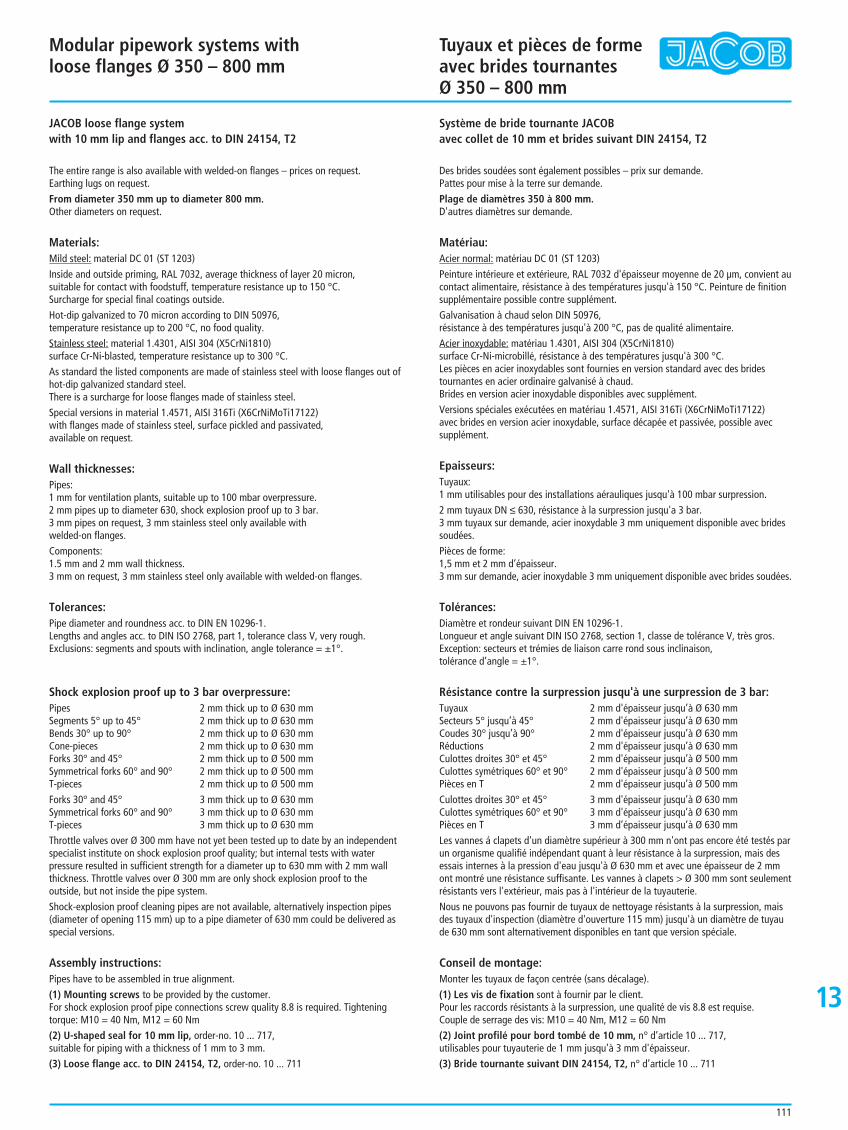
Modular pipework systems withloose flanges Ø 350 – 800 mm
Tuyaux et pièces de formeavec brides tournantes Ø 350 – 800 mm
111
13
JACOB loose flange systemwith 10 mm lip and flanges acc. to DIN 24154, T2
The entire range is also available with welded-on flanges – prices on request. Earthing lugs on request.From diameter 350 mm up to diameter 800 mm.Other diameters on request.
Materials:Mild steel: material DC 01 (ST 1203)Inside and outside priming, RAL 7032, average thickness of layer 20 micron, suitable for contact with foodstuff, temperature resistance up to 150 °C.Surcharge for special final coatings outside.Hot-dip galvanized to 70 micron according to DIN 50976,temperature resistance up to 200 °C, no food quality.Stainless steel: material 1.4301, AISI 304 (X5CrNi1810)surface Cr-Ni-blasted, temperature resistance up to 300 °C.As standard the listed components are made of stainless steel with loose flanges out ofhot-dip galvanized standard steel.There is a surcharge for loose flanges made of stainless steel.Special versions in material 1.4571, AISI 316Ti (X6CrNiMoTi17122)with flanges made of stainless steel, surface pickled and passivated, available on request.
Wall thicknesses:Pipes:1 mm for ventilation plants, suitable up to 100 mbar overpressure.2 mm pipes up to diameter 630, shock explosion proof up to 3 bar.3 mm pipes on request, 3 mm stainless steel only available with welded-on flanges.Components:1.5 mm and 2 mm wall thickness.3 mm on request, 3 mm stainless steel only available with welded-on flanges.
Tolerances:Pipe diameter and roundness acc. to DIN EN 10296-1.Lengths and angles acc. to DIN ISO 2768, part 1, tolerance class V, very rough.Exclusions: segments and spouts with inclination, angle tolerance = ±1°.
Shock explosion proof up to 3 bar overpressure:Pipes 2 mm thick up to Ø 630 mmSegments 5° up to 45° 2 mm thick up to Ø 630 mmBends 30° up to 90° 2 mm thick up to Ø 630 mmCone-pieces 2 mm thick up to Ø 630 mmForks 30° and 45° 2 mm thick up to Ø 500 mmSymmetrical forks 60° and 90° 2 mm thick up to Ø 500 mmT-pieces 2 mm thick up to Ø 500 mmForks 30° and 45° 3 mm thick up to Ø 630 mmSymmetrical forks 60° and 90° 3 mm thick up to Ø 630 mmT-pieces 3 mm thick up to Ø 630 mmThrottle valves over Ø 300 mm have not yet been tested up to date by an independentspecialist institute on shock explosion proof quality; but internal tests with waterpressure resulted in sufficient strength for a diameter up to 630 mm with 2 mm wallthickness. Throttle valves over Ø 300 mm are only shock explosion proof to theoutside, but not inside the pipe system.Shock-explosion proof cleaning pipes are not available, alternatively inspection pipes(diameter of opening 115 mm) up to a pipe diameter of 630 mm could be delivered asspecial versions.
Assembly instructions:Pipes have to be assembled in true alignment.(1) Mounting screws to be provided by the customer.For shock explosion proof pipe connections screw quality 8.8 is required. Tighteningtorque: M10 = 40 Nm, M12 = 60 Nm(2) U-shaped seal for 10 mm lip, order-no. 10 ... 717, suitable for piping with a thickness of 1 mm to 3 mm.(3) Loose flange acc. to DIN 24154, T2, order-no. 10 ... 711
Système de bride tournante JACOBavec collet de 10 mm et brides suivant DIN 24154, T2
Des brides soudées sont également possibles – prix sur demande.Pattes pour mise à la terre sur demande.Plage de diamètres 350 à 800 mm.D'autres diamètres sur demande.
Matériau:Acier normal: matériau DC 01 (ST 1203)Peinture intérieure et extérieure, RAL 7032 d'épaisseur moyenne de 20 µm, convient aucontact alimentaire, résistance à des températures jusqu'à 150 °C. Peinture de finitionsupplémentaire possible contre supplément.Galvanisation à chaud selon DIN 50976, résistance à des températures jusqu'à 200 °C, pas de qualité alimentaire.Acier inoxydable: matériau 1.4301, AISI 304 (X5CrNi1810)surface Cr-Ni-microbillé, résistance à des températures jusqu'à 300 °C.Les pièces en acier inoxydables sont fournies en version standard avec des bridestournantes en acier ordinaire galvanisé à chaud.Brides en version acier inoxydable disponibles avec supplément.Versions spéciales exécutées en matériau 1.4571, AISI 316Ti (X6CrNiMoTi17122) avec brides en version acier inoxydable, surface décapée et passivée, possible avecsupplément.
Epaisseurs:Tuyaux:1 mm utilisables pour des installations aérauliques jusqu'à 100 mbar surpression.2 mm tuyaux DN ≤ 630, résistance à la surpression jusqu'a 3 bar.3 mm tuyaux sur demande, acier inoxydable 3 mm uniquement disponible avec bridessoudées.Pièces de forme:1,5 mm et 2 mm d’épaisseur.3 mm sur demande, acier inoxydable 3 mm uniquement disponible avec brides soudées.
Tolérances:Diamètre et rondeur suivant DIN EN 10296-1.Longueur et angle suivant DIN ISO 2768, section 1, classe de tolérance V, très gros.Exception: secteurs et trémies de liaison carre rond sous inclinaison, tolérance d’angle = ±1°.
Résistance contre la surpression jusqu'à une surpression de 3 bar:Tuyaux 2 mm d'épaisseur jusqu’à Ø 630 mmSecteurs 5° jusqu’à 45° 2 mm d'épaisseur jusqu’à Ø 630 mmCoudes 30° jusqu’à 90° 2 mm d'épaisseur jusqu’à Ø 630 mmRéductions 2 mm d'épaisseur jusqu’à Ø 630 mmCulottes droites 30° et 45° 2 mm d'épaisseur jusqu’à Ø 500 mmCulottes symétriques 60° et 90° 2 mm d'épaisseur jusqu’à Ø 500 mmPièces en T 2 mm d'épaisseur jusqu’à Ø 500 mmCulottes droites 30° et 45° 3 mm d'épaisseur jusqu’à Ø 630 mmCulottes symétriques 60° et 90° 3 mm d'épaisseur jusqu’à Ø 630 mmPièces en T 3 mm d’épaisseur jusqu’à Ø 630 mmLes vannes á clapets d'un diamètre supérieur à 300 mm n'ont pas encore été testés parun organisme qualifié indépendant quant à leur résistance à la surpression, mais desessais internes à la pression d'eau jusqu'à Ø 630 mm et avec une épaisseur de 2 mmont montré une résistance suffisante. Les vannes à clapets > Ø 300 mm sont seulementrésistants vers l'extérieur, mais pas à l'intérieur de la tuyauterie.Nous ne pouvons pas fournir de tuyaux de nettoyage résistants à la surpression, maisdes tuyaux d'inspection (diamètre d'ouverture 115 mm) jusqu'à un diamètre de tuyaude 630 mm sont alternativement disponibles en tant que version spéciale.
Conseil de montage:Monter les tuyaux de façon centrée (sans décalage).(1) Les vis de fixation sont à fournir par le client.Pour les raccords résistants à la surpression, une qualité de vis 8.8 est requise. Couple de serrage des vis: M10 = 40 Nm, M12 = 60 Nm(2) Joint profilé pour bord tombé de 10 mm, n° d’article 10 ... 717,utilisables pour tuyauterie de 1 mm jusqu’à 3 mm d'épaisseur.(3) Bride tournante suivant DIN 24154, T2, n° d’article 10 ... 711
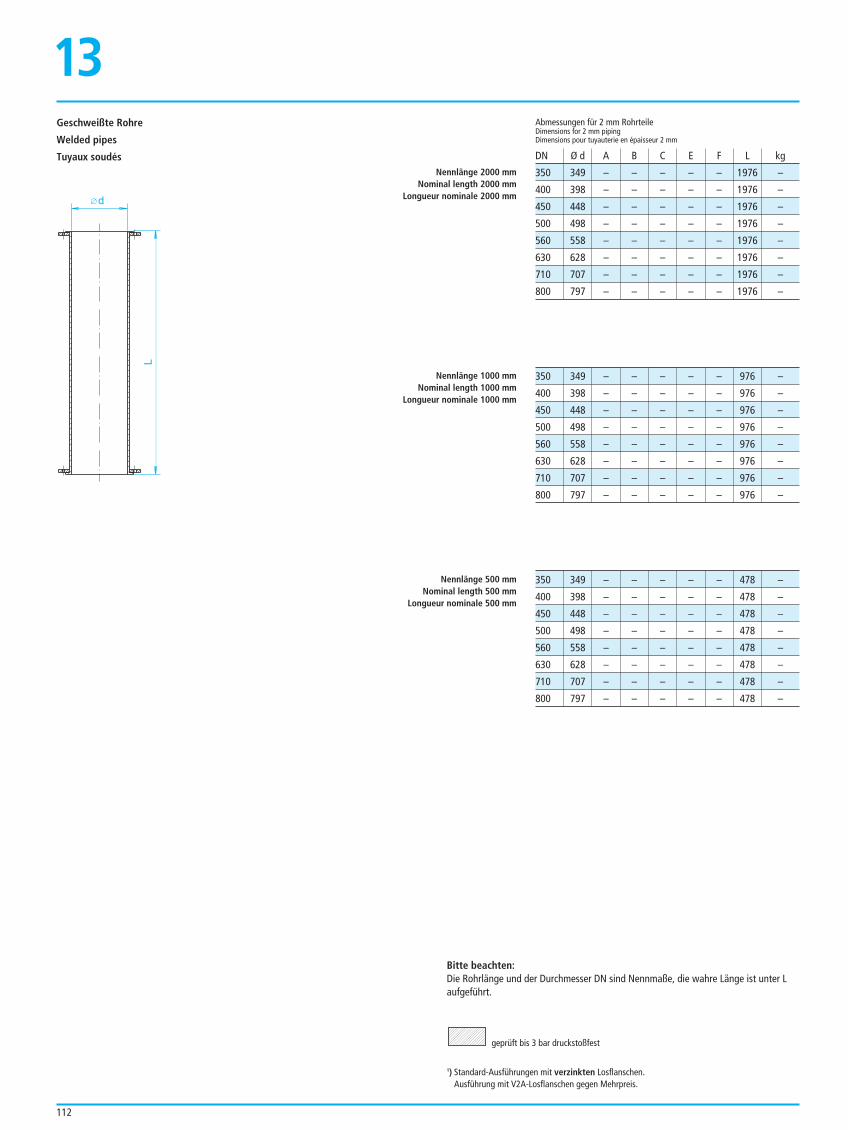
112
Geschweißte Rohre
Welded pipes
Tuyaux soudés350 349 – – – – – 1976 –
400 398 – – – – – 1976 –
450 448 – – – – – 1976 –
500 498 – – – – – 1976 –
560 558 – – – – – 1976 –
630 628 – – – – – 1976 –
710 707 – – – – – 1976 –
800 797 – – – – – 1976 –
Abmessungen für 2 mm RohrteileDimensions for 2 mm pipingDimensions pour tuyauterie en épaisseur 2 mm
DN Ø d A B C E F L kg
350 349 – – – – – 976 –
400 398 – – – – – 976 –
450 448 – – – – – 976 –
500 498 – – – – – 976 –
560 558 – – – – – 976 –
630 628 – – – – – 976 –
710 707 – – – – – 976 –
800 797 – – – – – 976 –
350 349 – – – – – 478 –
400 398 – – – – – 478 –
450 448 – – – – – 478 –
500 498 – – – – – 478 –
560 558 – – – – – 478 –
630 628 – – – – – 478 –
710 707 – – – – – 478 –
800 797 – – – – – 478 –
Bitte beachten:Die Rohrlänge und der Durchmesser DN sind Nennmaße, die wahre Länge ist unter Laufgeführt.
geprüft bis 3 bar druckstoßfest
1) Standard-Ausführungen mit verzinkten Losflanschen.Ausführung mit V2A-Losflanschen gegen Mehrpreis.
Nennlänge 2000 mmNominal length 2000 mm
Longueur nominale 2000 mm
Nennlänge 1000 mmNominal length 1000 mm
Longueur nominale 1000 mm
Nennlänge 500 mmNominal length 500 mm
Longueur nominale 500 mm
L
d
13
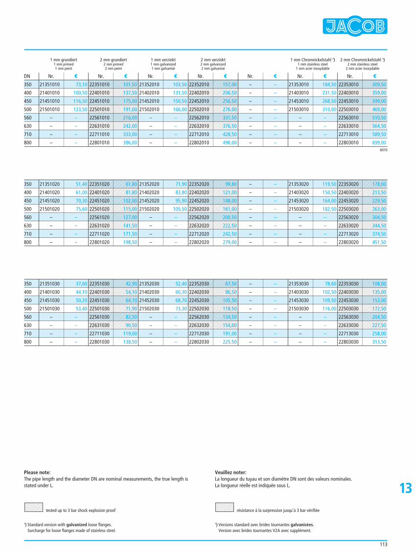
113
1 mm grundiert 2 mm grundiert 1 mm verzinkt 2 mm verzinkt 1 mm Chromnickelstahl 1) 2 mm Chromnickelstahl 1)1 mm primed 2 mm primed 1 mm galvanized 2 mm galvanized 1 mm stainless steel 2 mm stainless steel1 mm peint 2 mm peint 1 mm galvanisé 2 mm galvanisé 1 mm acier inoxydable 2 mm acier inoxydable
21351010 73,10
21401010 100,50
21451010 116,50
21501010 123,50
– –
– –
– –
– –
21352010 103,50
21402010 131,50
21452010 150,50
21502010 166,00
– –
– –
– –
– –
– –
– –
– –
– –
– –
– –
– –
– –
21353010 184,50
21403010 231,50
21453010 268,50
21503010 310,00
– –
– –
– –
– –
Nr. € Nr. € Nr. € Nr. € Nr. € Nr. € Nr. €DN
6010
350
400
450
500
560
630
710
800
21351020 51,40
21401020 61,00
21451020 70,30
21501020 75,60
– –
– –
– –
– –
21352020 71,90
21402020 83,80
21452020 95,90
21502020 105,50
– –
– –
– –
– –
– –
– –
– –
– –
– –
– –
– –
– –
21353020 119,50
21403020 150,50
21453020 164,00
21503020 182,50
– –
– –
– –
– –
350
400
450
500
560
630
710
800
21351030 37,60
21401030 44,10
21451030 50,20
21501030 53,40
– –
– –
– –
– –
21352030 52,40
21402030 60,30
21452030 68,70
21502030 73,30
– –
– –
– –
– –
– –
– –
– –
– –
– –
– –
– –
– –
21353030 78,60
21403030 102,50
21453030 109,50
21503030 116,00
– –
– –
– –
– –
350
400
450
500
560
630
710
800
Please note:The pipe length and the diameter DN are nominal measurements, the true length isstated under L.
tested up to 3 bar shock explosion proof
1) Standard version with galvanized loose flanges.Surcharge for loose flanges made of stainless steel.
Veuillez noter:La longueur du tuyau et son diamètre DN sont des valeurs nominales. La longueur réelle est indiquée sous L.
résistance à la surpression jusqu'à 3 bar vérifiée
1) Versions standard avec brides tournantes galvanisées.Version avec brides tournantes V2A avec supplément.
22351010 101,50
22401010 137,50
22451010 175,00
22501010 191,00
22561010 216,00
22631010 242,00
22711010 333,00
22801010 386,00
22352010 157,00
22402010 206,50
22452010 256,50
22502010 276,00
22562010 331,50
22632010 376,50
22712010 428,50
22802010 490,00
22353010 309,50
22403010 359,00
22453010 399,00
22503010 469,00
22563010 510,50
22633010 564,50
22713010 589,50
22803010 699,00
22351020 61,80
22401020 81,80
22451020 102,00
22501020 115,00
22561020 127,00
22631020 141,50
22711020 171,50
22801020 198,50
22352020 99,80
22402020 121,00
22452020 148,00
22502020 161,00
22562020 200,50
22632020 222,50
22712020 242,50
22802020 279,00
22353020 178,00
22403020 213,50
22453020 229,50
22503020 263,00
22563020 304,50
22633020 344,50
22713020 374,50
22803020 451,50
22351030 42,90
22401030 54,10
22451030 64,10
22501030 71,90
22561030 82,50
22631030 90,50
22711030 119,00
22801030 138,50
22352030 67,50
22402030 86,50
22452030 105,50
22502030 118,50
22562030 134,50
22632030 154,00
22712030 191,00
22802030 225,50
22353030 108,00
22403030 135,00
22453030 153,00
22503030 172,50
22563030 204,50
22633030 227,50
22713030 258,00
22803030 313,50
13
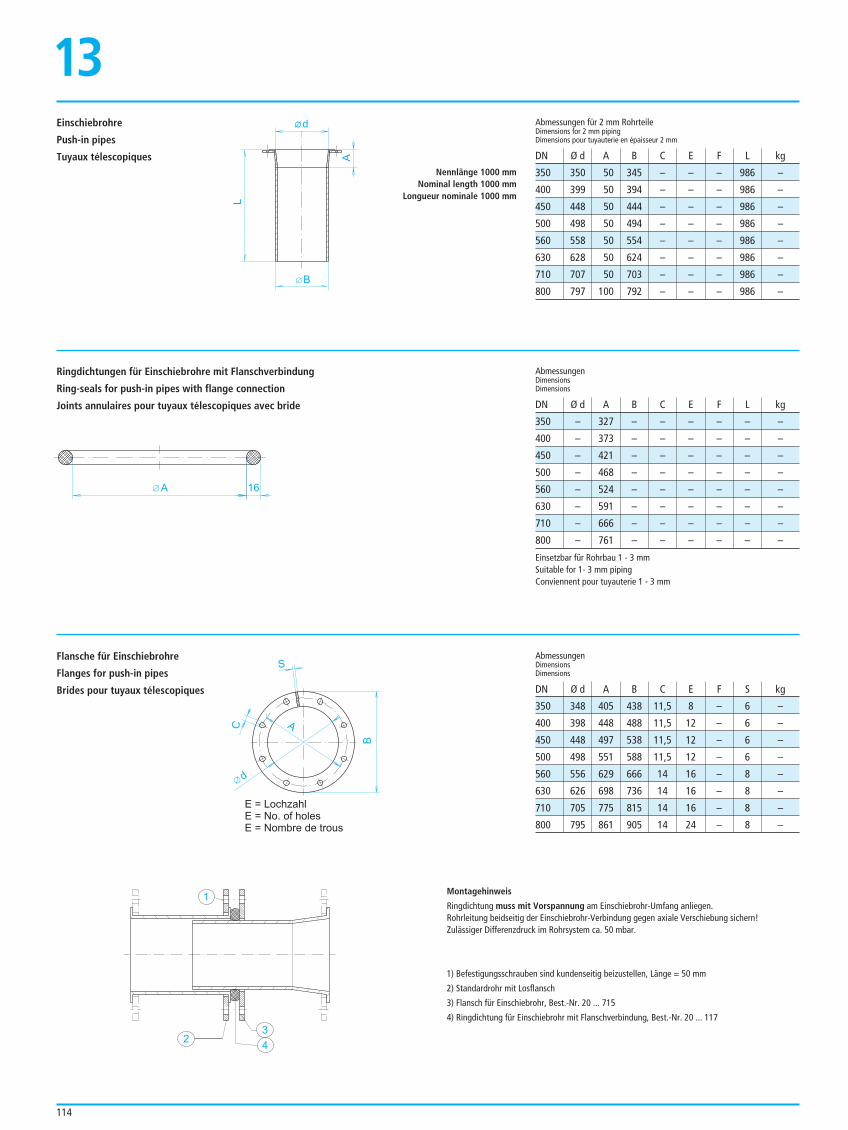
350 348 405 438 11,5 8 – 6 –
400 398 448 488 11,5 12 – 6 –
450 448 497 538 11,5 12 – 6 –
500 498 551 588 11,5 12 – 6 –
560 556 629 666 14 16 – 8 –
630 626 698 736 14 16 – 8 –
710 705 775 815 14 16 – 8 –
800 795 861 905 14 24 – 8 –
AbmessungenDimensions Dimensions
DN Ø d A B C E F S kg
114
Einschiebrohre
Push-in pipes
Tuyaux télescopiques
Ringdichtungen für Einschiebrohre mit Flanschverbindung
Ring-seals for push-in pipes with flange connection
Joints annulaires pour tuyaux télescopiques avec bride
Flansche für Einschiebrohre
Flanges for push-in pipes
Brides pour tuyaux télescopiques
350 350 50 345 – – – 986 –
400 399 50 394 – – – 986 –
450 448 50 444 – – – 986 –
500 498 50 494 – – – 986 –
560 558 50 554 – – – 986 –
630 628 50 624 – – – 986 –
710 707 50 703 – – – 986 –
800 797 100 792 – – – 986 –
Abmessungen für 2 mm RohrteileDimensions for 2 mm pipingDimensions pour tuyauterie en épaisseur 2 mm
DN Ø d A B C E F L kg
Montagehinweis
Ringdichtung muss mit Vorspannung am Einschiebrohr-Umfang anliegen.Rohrleitung beidseitig der Einschiebrohr-Verbindung gegen axiale Verschiebung sichern!Zulässiger Differenzdruck im Rohrsystem ca. 50 mbar.
1) Befestigungsschrauben sind kundenseitig beizustellen, Länge = 50 mm
2) Standardrohr mit Losflansch
3) Flansch für Einschiebrohr, Best.-Nr. 20 ... 715
4) Ringdichtung für Einschiebrohr mit Flanschverbindung, Best.-Nr. 20 ... 117
Nennlänge 1000 mmNominal length 1000 mm
Longueur nominale 1000 mm
d
A
L
B
13
16A
E = Lochzahl
E = No. of holes
E = Nombre de trous
S
C
B
A
d
1
23
4
350 – 327 – – – – – –
400 – 373 – – – – – –
450 – 421 – – – – – –
500 – 468 – – – – – –
560 – 524 – – – – – –
630 – 591 – – – – – –
710 – 666 – – – – – –
800 – 761 – – – – – –
AbmessungenDimensions Dimensions
DN Ø d A B C E F L kg
Einsetzbar für Rohrbau 1 - 3 mmSuitable for 1- 3 mm pipingConviennent pour tuyauterie 1 - 3 mm
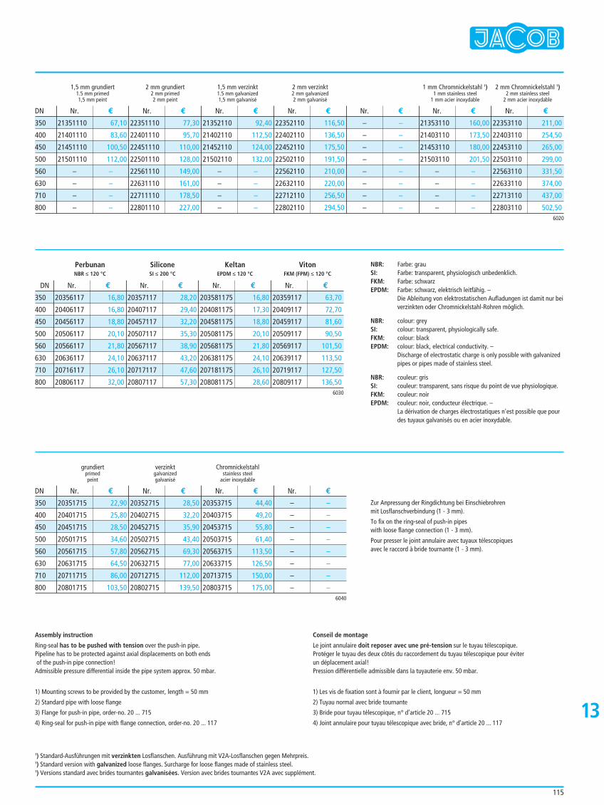
grundiert verzinkt Chromnickelstahlprimed galvanized stainless steelpeint galvanisé acier inoxydable
20351715 22,90
20401715 25,80
20451715 28,50
20501715 34,60
20561715 57,80
20631715 64,50
20711715 86,00
20801715 103,50
20352715 28,50
20402715 32,20
20452715 35,90
20502715 43,40
20562715 69,30
20632715 77,00
20712715 112,00
20802715 139,50
20353715 44,40
20403715 49,20
20453715 55,80
20503715 61,40
20563715 113,50
20633715 126,50
20713715 150,00
20803715 175,00
– –
– –
– –
– –
– –
– –
– –
– –
Nr. € Nr. € Nr. € Nr. €DN
6040
350
400
450
500
560
630
710
800
115
1,5 mm grundiert 2 mm grundiert 1,5 mm verzinkt 2 mm verzinkt 1 mm Chromnickelstahl 1) 2 mm Chromnickelstahl 1)1.5 mm primed 2 mm primed 1.5 mm galvanized 2 mm galvanized 1 mm stainless steel 2 mm stainless steel1,5 mm peint 2 mm peint 1,5 mm galvanisé 2 mm galvanisé 1 mm acier inoxydable 2 mm acier inoxydable
21351110 67,10
21401110 83,60
21451110 100,50
21501110 112,00
– –
– –
– –
– –
22351110 77,30
22401110 95,70
22451110 110,00
22501110 128,00
22561110 149,00
22631110 161,00
22711110 178,50
22801110 227,00
21352110 92,40
21402110 112,50
21452110 124,00
21502110 132,00
– –
– –
– –
– –
22352110 116,50
22402110 136,50
22452110 175,50
22502110 191,50
22562110 210,00
22632110 220,00
22712110 256,50
22802110 294,50
– –
– –
– –
– –
– –
– –
– –
– –
21353110 160,00
21403110 173,50
21453110 180,00
21503110 201,50
– –
– –
– –
– –
22353110 211,00
22403110 254,50
22453110 265,00
22503110 299,00
22563110 331,50
22633110 374,00
22713110 437,00
22803110 502,50
Nr. € Nr. € Nr. € Nr. € Nr. € Nr. € Nr. €DN
6020
350
400
450
500
560
630
710
800
Assembly instruction
Ring-seal has to be pushed with tension over the push-in pipe.Pipeline has to be protected against axial displacements on both endsof the push-in pipe connection!
Admissible pressure differential inside the pipe system approx. 50 mbar.
1) Mounting screws to be provided by the customer, length = 50 mm
2) Standard pipe with loose flange
3) Flange for push-in pipe, order-no. 20 ... 715
4) Ring-seal for push-in pipe with flange connection, order-no. 20 ... 117
Conseil de montage
Le joint annulaire doit reposer avec une pré-tension sur le tuyau télescopique.Protéger le tuyau des deux côtés du raccordement du tuyau télescopique pour éviterun déplacement axial!Pression différentielle admissible dans la tuyauterie env. 50 mbar.
1) Les vis de fixation sont à fournir par le client, longueur = 50 mm
2) Tuyau normal avec bride tournante
3) Bride pour tuyau télescopique, n° d’article 20 ... 715
4) Joint annulaire pour tuyau télescopique avec bride, n° d’article 20 ... 11713
Perbunan Silicone Keltan VitonNBR ≤ 120 °C SI ≤ 200 °C EPDM ≤ 120 °C FKM (FPM) ≤ 120 °C
20356117 16,80
20406117 16,80
20456117 18,80
20506117 20,10
20566117 21,80
20636117 24,10
20716117 26,10
20806117 32,00
20357117 28,20
20407117 29,40
20457117 32,20
20507117 35,30
20567117 38,90
20637117 43,20
20717117 47,60
20807117 57,30
203581175 16,80
204081175 17,30
204581175 18,80
205081175 20,10
205681175 21,80
206381175 24,10
207181175 26,10
208081175 28,60
20359117 63,70
20409117 72,70
20459117 81,60
20509117 90,50
20569117 101,50
20639117 113,50
20719117 127,50
20809117 136,50
Nr. € Nr. € Nr. € Nr. €DN
6030
350
400
450
500
560
630
710
800
NBR: Farbe: grauSI: Farbe: transparent, physiologisch unbedenklich.FKM: Farbe: schwarzEPDM: Farbe: schwarz, elektrisch leitfähig. –
Die Ableitung von elektrostatischen Aufladungen ist damit nur beiverzinkten oder Chromnickelstahl-Rohren möglich.
NBR: colour: greySI: colour: transparent, physiologically safe.FKM: colour: blackEPDM: colour: black, electrical conductivity. –
Discharge of electrostatic charge is only possible with galvanizedpipes or pipes made of stainless steel.
NBR: couleur: grisSI: couleur: transparent, sans risque du point de vue physiologique.FKM: couleur: noirEPDM: couleur: noir, conducteur électrique. –
La dérivation de charges électrostatiques n'est possible que pourdes tuyaux galvanisés ou en acier inoxydable.
Zur Anpressung der Ringdichtung bei Einschiebrohrenmit Losflanschverbindung (1 - 3 mm).
To fix on the ring-seal of push-in pipeswith loose flange connection (1 - 3 mm).
Pour presser le joint annulaire avec tuyaux télescopiques avec le raccord à bride tournante (1 - 3 mm).
1) Standard-Ausführungen mit verzinkten Losflanschen. Ausführung mit V2A-Losflanschen gegen Mehrpreis.1) Standard version with galvanized loose flanges. Surcharge for loose flanges made of stainless steel.1) Versions standard avec brides tournantes galvanisées. Version avec brides tournantes V2A avec supplément.
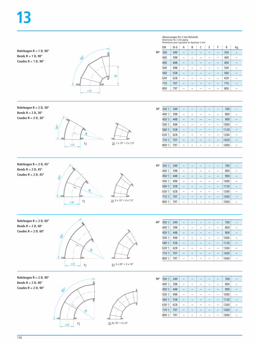
Rohrbogen R = 2 D, 60°
Bends R = 2 D, 60°
Coudes R = 2 D, 60°
350 1) 349 – – – – – 700 –
400 1) 398 – – – – – 800 –
450 2) 448 – – – – – 900 –
500 2) 498 – – – – – 1000 –
560 2) 558 – – – – – 1120 –
630 2) 628 – – – – – 1260 –
710 2) 707 – – – – – 1420 –
800 2) 797 – – – – – 1600 –
60°
Rohrbogen R = 2 D, 90°
Bends R = 2 D, 90°
Coudes R = 2 D, 90°
350 1) 349 – – – – – 700 –
400 1) 398 – – – – – 800 –
450 2) 448 – – – – – 900 –
500 2) 498 – – – – – 1000 –
560 2) 558 – – – – – 1120 –
630 2) 628 – – – – – 1260 –
710 2) 707 – – – – – 1420 –
800 2) 797 – – – – – 1600 –
90°
d 1)
R
30°
2) 1 x 15° + 2 x 7,5°
2) 2 x 15° + 2 x 7,5°d
R
45°
1)
2) 2 x 20° + 2 x 10°d
R
60°
1)
2) 4x 18° + 2 x 9°d
R
90°
1)
116
Rohrbogen R = 1 D, 90°
Bends R = 1 D, 90°
Coudes R = 1 D, 90°
Rohrbogen R = 2 D, 30°
Bends R = 2 D, 30°
Coudes R = 2 D, 30°
Rohrbogen R = 2 D, 45°
Bends R = 2 D, 45°
Coudes R = 2 D, 45°
350 349 – – – – – 350 –
400 398 – – – – – 400 –
450 448 – – – – – 450 –
500 498 – – – – – 500 –
560 558 – – – – – 560 –
630 628 – – – – – 630 –
710 707 – – – – – 710 –
800 797 – – – – – 800 –
Abmessungen für 2 mm RohrteileDimensions for 2 mm pipingDimensions pour tuyauterie en épaisseur 2 mm
DN Ø d A B C E F R kg
350 1) 349 – – – – – 700 –
400 1) 398 – – – – – 800 –
450 2) 448 – – – – – 900 –
500 2) 498 – – – – – 1000 –
560 2) 558 – – – – – 1120 –
630 2) 628 – – – – – 1260 –
710 2) 707 – – – – – 1420 –
800 2) 797 – – – – – 1600 –
350 1) 349 – – – – – 700 –
400 1) 398 – – – – – 800 –
450 2) 448 – – – – – 900 –
500 2) 498 – – – – – 1000 –
560 2) 558 – – – – – 1120 –
630 2) 628 – – – – – 1260 –
710 2) 707 – – – – – 1420 –
800 2) 797 – – – – – 1600 –
90°
30°
45°
d
90°
R
13
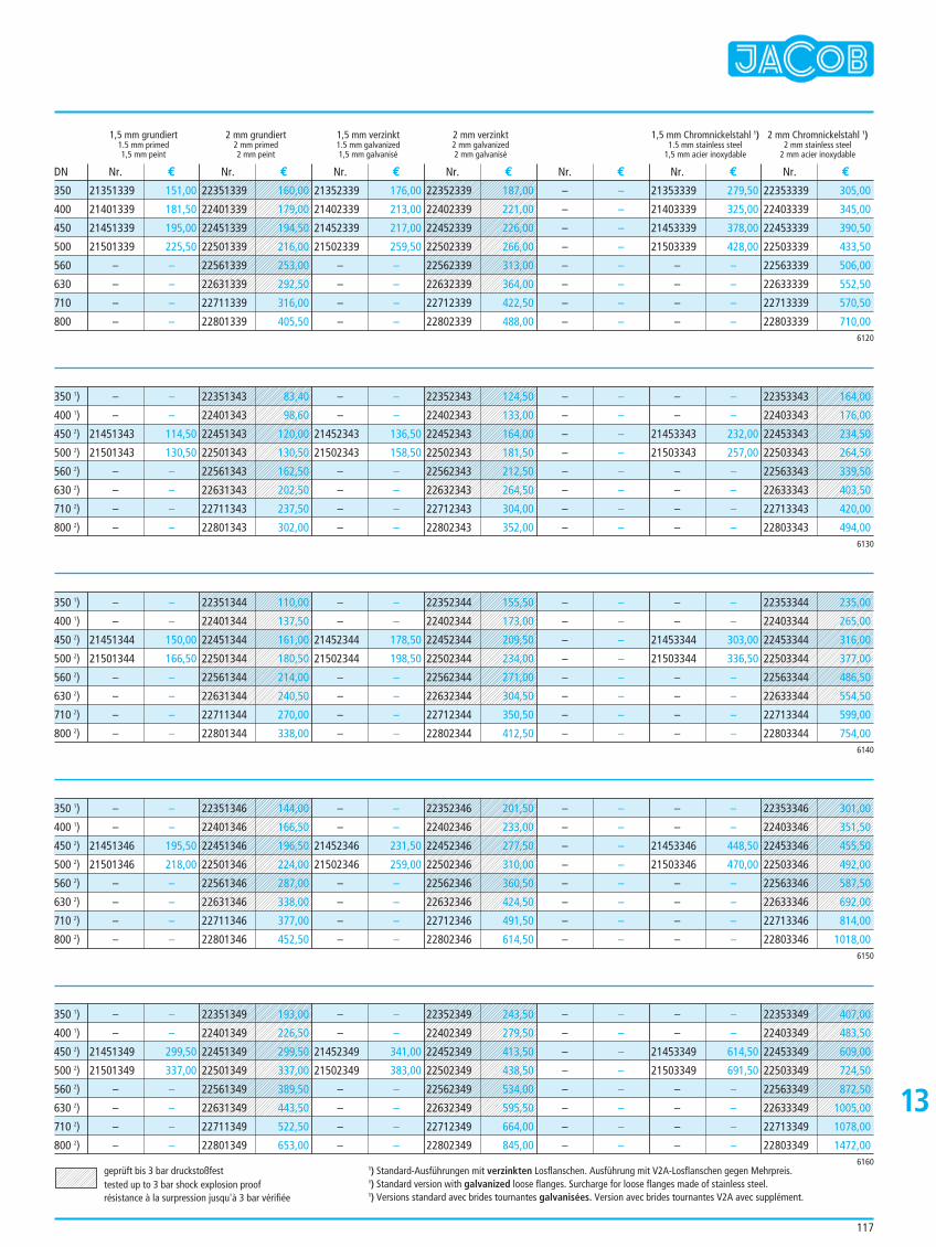
117
1,5 mm grundiert 2 mm grundiert 1,5 mm verzinkt 2 mm verzinkt 1,5 mm Chromnickelstahl 1) 2 mm Chromnickelstahl 1)1.5 mm primed 2 mm primed 1.5 mm galvanized 2 mm galvanized 1.5 mm stainless steel 2 mm stainless steel1,5 mm peint 2 mm peint 1,5 mm galvanisé 2 mm galvanisé 1,5 mm acier inoxydable 2 mm acier inoxydable
21351339 151,00
21401339 181,50
21451339 195,00
21501339 225,50
– –
– –
– –
– –
21352339 176,00
21402339 213,00
21452339 217,00
21502339 259,50
– –
– –
– –
– –
– –
– –
– –
– –
– –
– –
– –
– –
21353339 279,50
21403339 325,00
21453339 378,00
21503339 428,00
– –
– –
– –
– –
22353339 305,00
22403339 345,00
22453339 390,50
22503339 433,50
22563339 506,00
22633339 552,50
22713339 570,50
22803339 710,00
Nr. € Nr. € Nr. € Nr. € Nr. € Nr. € Nr. €DN
6120
350
400
450
500
560
630
710
800
– –
– –
21451343 114,50
21501343 130,50
– –
– –
– –
– –
– –
– –
21452343 136,50
21502343 158,50
– –
– –
– –
– –
– –
– –
– –
– –
– –
– –
– –
– –
– –
– –
21453343 232,00
21503343 257,00
– –
– –
– –
– –6130
350 1)
400 1)
450 2)
500 2)
560 2)
630 2)
710 2)
800 2)
– –
– –
21451344 150,00
21501344 166,50
– –
– –
– –
– –
– –
– –
21452344 178,50
21502344 198,50
– –
– –
– –
– –
– –
– –
– –
– –
– –
– –
– –
– –
– –
– –
21453344 303,00
21503344 336,50
– –
– –
– –
– –6140
350 1)
400 1)
450 2)
500 2)
560 2)
630 2)
710 2)
800 2)
geprüft bis 3 bar druckstoßfesttested up to 3 bar shock explosion proofrésistance à la surpression jusqu'à 3 bar vérifiée
1) Standard-Ausführungen mit verzinkten Losflanschen. Ausführung mit V2A-Losflanschen gegen Mehrpreis.1) Standard version with galvanized loose flanges. Surcharge for loose flanges made of stainless steel.1) Versions standard avec brides tournantes galvanisées. Version avec brides tournantes V2A avec supplément.
– –
– –
21451346 195,50
21501346 218,00
– –
– –
– –
– –
– –
– –
21452346 231,50
21502346 259,00
– –
– –
– –
– –
– –
– –
– –
– –
– –
– –
– –
– –
– –
– –
21453346 448,50
21503346 470,00
– –
– –
– –
– –6150
350 1)
400 1)
450 2)
500 2)
560 2)
630 2)
710 2)
800 2)
– –
– –
21451349 299,50
21501349 337,00
– –
– –
– –
– –
– –
– –
21452349 341,00
21502349 383,00
– –
– –
– –
– –
– –
– –
– –
– –
– –
– –
– –
– –
– –
– –
21453349 614,50
21503349 691,50
– –
– –
– –
– –6160
350 1)
400 1)
450 2)
500 2)
560 2)
630 2)
710 2)
800 2)
22351343 83,40
22401343 98,60
22451343 120,00
22501343 130,50
22561343 162,50
22631343 202,50
22711343 237,50
22801343 302,00
22352343 124,50
22402343 133,00
22452343 164,00
22502343 181,50
22562343 212,50
22632343 264,50
22712343 304,00
22802343 352,00
22353343 164,00
22403343 176,00
22453343 234,50
22503343 264,50
22563343 339,50
22633343 403,50
22713343 420,00
22803343 494,00
22353344 235,00
22403344 265,00
22453344 316,00
22503344 377,00
22563344 486,50
22633344 554,50
22713344 599,00
22803344 754,00
22352344 155,50
22402344 173,00
22452344 209,50
22502344 234,00
22562344 271,00
22632344 304,50
22712344 350,50
22802344 412,50
22351344 110,00
22401344 137,50
22451344 161,00
22501344 180,50
22561344 214,00
22631344 240,50
22711344 270,00
22801344 338,00
13
22353346 301,00
22403346 351,50
22453346 455,50
22503346 492,00
22563346 587,50
22633346 692,00
22713346 814,00
22803346 1018,00
22352346 201,50
22402346 233,00
22452346 277,50
22502346 310,00
22562346 360,50
22632346 424,50
22712346 491,50
22802346 614,50
22351346 144,00
22401346 166,50
22451346 196,50
22501346 224,00
22561346 287,00
22631346 338,00
22711346 377,00
22801346 452,50
22353349 407,00
22403349 483,50
22453349 609,00
22503349 724,50
22563349 872,50
22633349 1005,00
22713349 1078,00
22803349 1472,00
22352349 243,50
22402349 279,50
22452349 413,50
22502349 438,50
22562349 534,00
22632349 595,50
22712349 664,00
22802349 845,00
22351349 193,00
22401349 226,50
22451349 299,50
22501349 337,00
22561349 389,50
22631349 443,50
22711349 522,50
22801349 653,00
22351339 160,00
22401339 179,00
22451339 194,50
22501339 216,00
22561339 253,00
22631339 292,50
22711339 316,00
22801339 405,50
22352339 187,00
22402339 221,00
22452339 226,00
22502339 266,00
22562339 313,00
22632339 364,00
22712339 422,50
22802339 488,00
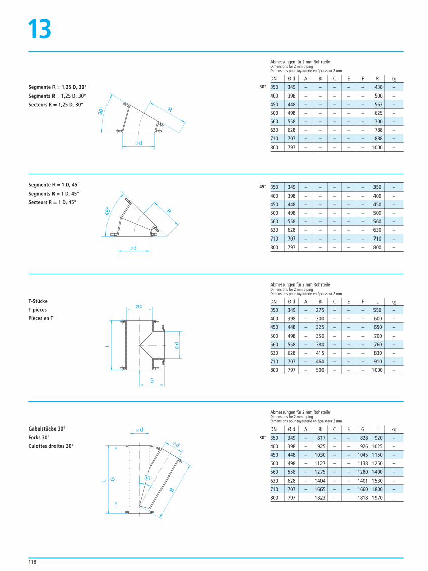
118
Segmente R = 1,25 D, 30°
Segments R = 1,25 D, 30°
Secteurs R = 1,25 D, 30°
Segmente R = 1 D, 45°
Segments R = 1 D, 45°
Secteurs R = 1 D, 45°
T-Stücke
T-pieces
Pièces en T
Gabelstücke 30°
Forks 30°
Culottes droites 30°
350 349 – – – – – 438 –
400 398 – – – – – 500 –
450 448 – – – – – 563 –
500 498 – – – – – 625 –
560 558 – – – – – 700 –
630 628 – – – – – 788 –
710 707 – – – – – 888 –
800 797 – – – – – 1000 –
Abmessungen für 2 mm RohrteileDimensions for 2 mm pipingDimensions pour tuyauterie en épaisseur 2 mm
Abmessungen für 2 mm RohrteileDimensions for 2 mm pipingDimensions pour tuyauterie en épaisseur 2 mm
Abmessungen für 2 mm RohrteileDimensions for 2 mm pipingDimensions pour tuyauterie en épaisseur 2 mm
DN Ø d A B C E F R kg
DN Ø d A B C E G L kg
DN Ø d A B C E F L kg
350 349 – – – – – 350 –
400 398 – – – – – 400 –
450 448 – – – – – 450 –
500 498 – – – – – 500 –
560 558 – – – – – 560 –
630 628 – – – – – 630 –
710 707 – – – – – 710 –
800 797 – – – – – 800 –
350 349 – 275 – – – 550 –
400 398 – 300 – – – 600 –
450 448 – 325 – – – 650 –
500 498 – 350 – – – 700 –
560 558 – 380 – – – 760 –
630 628 – 415 – – – 830 –
710 707 – 460 – – – 910 –
800 797 – 500 – – – 1000 –
350 349 – 817 – – 828 920 –
400 398 – 925 – – 926 1025 –
450 448 – 1030 – – 1045 1150 –
500 498 – 1127 – – 1138 1250 –
560 558 – 1275 – – 1280 1400 –
630 628 – 1404 – – 1401 1530 –
710 707 – 1665 – – 1660 1800 –
800 797 – 1823 – – 1818 1970 –
30°
45°
30°
d
R
30°
d
d
L
B
d
d
B
G
30°
L
13
R
d
45°
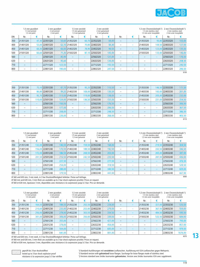
21351230 164,50
21401230 210,00
21451230 256,00
21501230 301,00
– –
– –
– –
– –
21352230 202,50
21402230 253,00
21452230 303,50
21502230 350,00
– –
– –
– –
– –
– –
– –
– –
– –
– –
– –
– –
– –
21353230 327,00
21403230 367,50
21453230 484,50
21503230 532,50
– –
– –
– –
– –6070
350
400
450
500
560
630
710
800
Ø 560 und 630 mm, 3 mm stark, in 3 bar Druckstoßfestigkeit lieferbar. Preise auf Anfrage.Ø 560 mm and 630 mm, 3 mm thick are available up to 3 bar shock explosion proofed. Prices on request.Ø 560 et 630 mm, épaisseur 3 mm, disponibles avec résistance à la surpression jusqu'à 3 bar. Prix sur demande.
119
1,5 mm grundiert 2 mm grundiert 1,5 mm verzinkt 2 mm verzinkt 1,5 mm Chromnickelstahl 1) 2 mm Chromnickelstahl 1)1.5 mm primed 2 mm primed 1.5 mm galvanized 2 mm galvanized 1.5 mm stainless steel 2 mm stainless steel1,5 mm peint 2 mm peint 1,5 mm galvanisé 2 mm galvanisé 1,5 mm acier inoxydable 2 mm acier inoxydable
1,5 mm grundiert 2 mm grundiert 1,5 mm verzinkt 2 mm verzinkt 1,5 mm Chromnickelstahl 1) 2 mm Chromnickelstahl 1)1.5 mm primed 2 mm primed 1.5 mm galvanized 2 mm galvanized 1.5 mm stainless steel 2 mm stainless steel1,5 mm peint 2 mm peint 1,5 mm galvanisé 2 mm galvanisé 1,5 mm acier inoxydable 2 mm acier inoxydable
1,5 mm grundiert 2 mm grundiert 1,5 mm verzinkt 2 mm verzinkt 1,5 mm Chromnickelstahl 1) 2 mm Chromnickelstahl 1)1.5 mm primed 2 mm primed 1.5 mm galvanized 2 mm galvanized 1.5 mm stainless steel 2 mm stainless steel1,5 mm peint 2 mm peint 1,5 mm galvanisé 2 mm galvanisé 1,5 mm acier inoxydable 2 mm acier inoxydable
21351320 47,30
21401320 53,00
21451320 60,30
21501320 66,60
– –
– –
– –
– –
21352320 60,70
21402320 70,80
21452320 78,90
21502320 87,10
– –
– –
– –
– –
– –
– –
– –
– –
– –
– –
– –
– –
21353320 93,80
21403320 109,50
21453320 123,00
21503320 133,00
– –
– –
– –
– –
Nr. € Nr. € Nr. € Nr. € Nr. € Nr. € Nr. €
Nr. € Nr. € Nr. € Nr. € Nr. € Nr. € Nr. €
Nr. € Nr. € Nr. € Nr. € Nr. € Nr. € Nr. €
DN
DN
DN
6100
350
400
450
500
560
630
710
800
21351330 75,10
21401330 86,80
21451330 95,70
21501330 110,00
– –
– –
– –
– –
21352330 95,20
21402330 108,00
21452330 119,00
21502330 136,50
– –
– –
– –
– –
– –
– –
– –
– –
– –
– –
– –
– –
21353330 146,50
21403330 183,00
21453330 205,00
21503330 231,00
– –
– –
– –
– –6110
350
400
450
500
560
630
710
800
21351240 132,00
21401240 156,00
21451240 172,00
21501240 201,50
– –
– –
– –
– –
21352240 159,50
21402240 188,50
21452240 208,50
21502240 242,50
– –
– –
– –
– –
– –
– –
– –
– –
– –
– –
– –
– –
21353240 219,50
21403240 243,50
21453240 265,00
21503240 287,00
– –
– –
– –
– –6060
350
400
450
500
560
630
710
800
Ø 560 und 630 mm, 3 mm stark, in 3 bar Druckstoßfestigkeit lieferbar. Preise auf Anfrage.Ø 560 mm and 630 mm, 3 mm thick are available up to 3 bar shock explosion proofed. Prices on request.Ø 560 et 630 mm, épaisseur 3 mm, disponibles avec résistance à la surpression jusqu'à 3 bar. Prix sur demande.
geprüft bis 3 bar druckstoßfesttested up to 3 bar shock explosion proofrésistance à la surpression jusqu'à 3 bar vérifiée
1) Standard-Ausführungen mit verzinkten Losflanschen. Ausführung mit V2A-Losflanschen gegen Mehrpreis.1) Standard version with galvanized loose flanges. Surcharge for loose flanges made of stainless steel.1) Versions standard avec brides tournantes galvanisées. Version avec brides tournantes V2A avec supplément.
22351320 50,60
22401320 62,10
22451320 66,00
22501320 71,30
22561320 85,90
22631320 95,60
22711320 123,50
22801320 190,00
22353320 103,00
22403320 127,50
22453320 135,50
22503320 146,00
22563320 176,50
22633320 208,50
22713320 240,50
22803320 296,50
22351330 87,70
22401330 99,20
22451330 113,00
22501330 124,00
22561330 150,50
22631330 177,00
22711330 208,00
22801330 226,00
22353330 171,50
22403330 201,00
22453330 232,00
22503330 254,50
22563330 306,50
22633330 367,50
22713330 386,50
22803330 405,50
22353240 304,50
22403240 346,50
22453240 387,00
22503240 436,00
22563240 476,50
22633240 528,50
22713240 609,00
22803240 667,00
13
22353230 520,50
22403230 559,00
22453230 595,50
22503230 684,00
22563230 793,00
22633230 857,00
22713230 979,50
22803230 1676,00
22351230 188,50
22401230 233,00
22451230 278,00
22501230 306,00
22561230 355,00
22631230 378,00
22711230 504,00
22801230 641,00
22352320 69,00
22402320 84,40
22452320 94,50
22502320 105,00
22562320 121,00
22632320 134,00
22712320 155,50
22802320 247,50
22352330 110,50
22402330 130,50
22452330 138,00
22502330 151,50
22562330 176,50
22632330 206,50
22712330 248,50
22802330 268,00
22352240 168,00
22402240 192,50
22452240 203,00
22502240 233,50
22562240 277,50
22632240 318,50
22712240 340,50
22802240 447,00
22351240 146,50
22401240 170,50
22451240 186,50
22501240 216,50
22561240 227,50
22631240 254,00
22711240 288,00
22801240 379,50
22352230 228,00
22402230 279,50
22452230 334,50
22502230 339,50
22562230 427,00
22632230 454,00
22712230 605,00
22802230 801,00
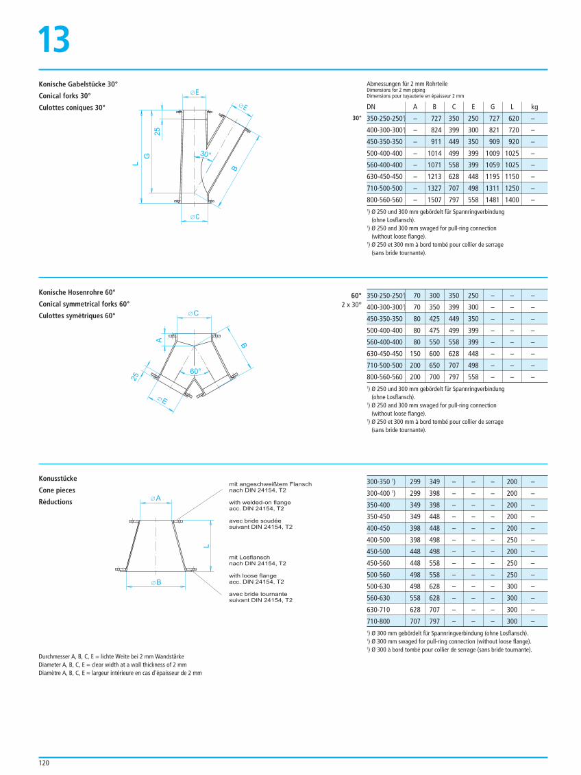
120
E
E
C
G
B
30°25
L
C
60°
B
E
25
A
350-250-2501) – 727 350 250 727 620 –
400-300-3001) – 824 399 300 821 720 –
450-350-350 – 911 449 350 909 920 –
500-400-400 – 1014 499 399 1009 1025 –
560-400-400 – 1071 558 399 1059 1025 –
630-450-450 – 1213 628 448 1195 1150 –
710-500-500 – 1327 707 498 1311 1250 –
800-560-560 – 1507 797 558 1481 1400 –
Abmessungen für 2 mm RohrteileDimensions for 2 mm pipingDimensions pour tuyauterie en épaisseur 2 mm
DN A B C E G L kg
1) Ø 250 und 300 mm gebördelt für Spannringverbindung (ohne Losflansch).
1) Ø 250 and 300 mm swaged for pull-ring connection(without loose flange).
1) Ø 250 et 300 mm à bord tombé pour collier de serrage (sans bride tournante).
30°
350-250-2501) 70 300 350 250 – – –
400-300-3001) 70 350 399 300 – – –
450-350-350 80 425 449 350 – – –
500-400-400 80 475 499 399 – – –
560-400-400 80 550 558 399 – – –
630-450-450 150 600 628 448 – – –
710-500-500 200 650 707 498 – – –
800-560-560 200 700 797 558 – – –1) Ø 250 und 300 mm gebördelt für Spannringverbindung
(ohne Losflansch).1) Ø 250 and 300 mm swaged for pull-ring connection
(without loose flange).1) Ø 250 et 300 mm à bord tombé pour collier de serrage
(sans bride tournante).
60°2 x 30°
300-350 1) 299 349 – – – 200 –
300-400 1) 299 398 – – – 200 –
350-400 349 398 – – – 200 –
350-450 349 448 – – – 200 –
400-450 398 448 – – – 200 –
400-500 398 498 – – – 250 –
450-500 448 498 – – – 200 –
450-560 448 558 – – – 250 –
500-560 498 558 – – – 250 –
500-630 498 628 – – – 300 –
560-630 558 628 – – – 300 –
630-710 628 707 – – – 300 –
710-800 707 797 – – – 300 –1) Ø 300 mm gebördelt für Spannringverbindung (ohne Losflansch).1) Ø 300 mm swaged for pull-ring connection (without loose flange).1) Ø 300 à bord tombé pour collier de serrage (sans bride tournante).
Durchmesser A, B, C, E = lichte Weite bei 2 mm WandstärkeDiameter A, B, C, E = clear width at a wall thickness of 2 mmDiamètre A, B, C, E = largeur intérieure en cas d'épaisseur de 2 mm
Konische Gabelstücke 30°
Conical forks 30°
Culottes coniques 30°
Konische Hosenrohre 60°
Conical symmetrical forks 60°
Culottes symétriques 60°
13
Konusstücke
Cone pieces
Réductions A
B
L
mit angeschweißtem Flansch
nach DIN 24154, T2
with welded-on flange
acc. DIN 24154, T2
avec bride soudée
suivant DIN 24154, T2
mit Losflansch
nach DIN 24154, T2
with loose flange
acc. DIN 24154, T2
avec bride tournante
suivant DIN 24154, T2
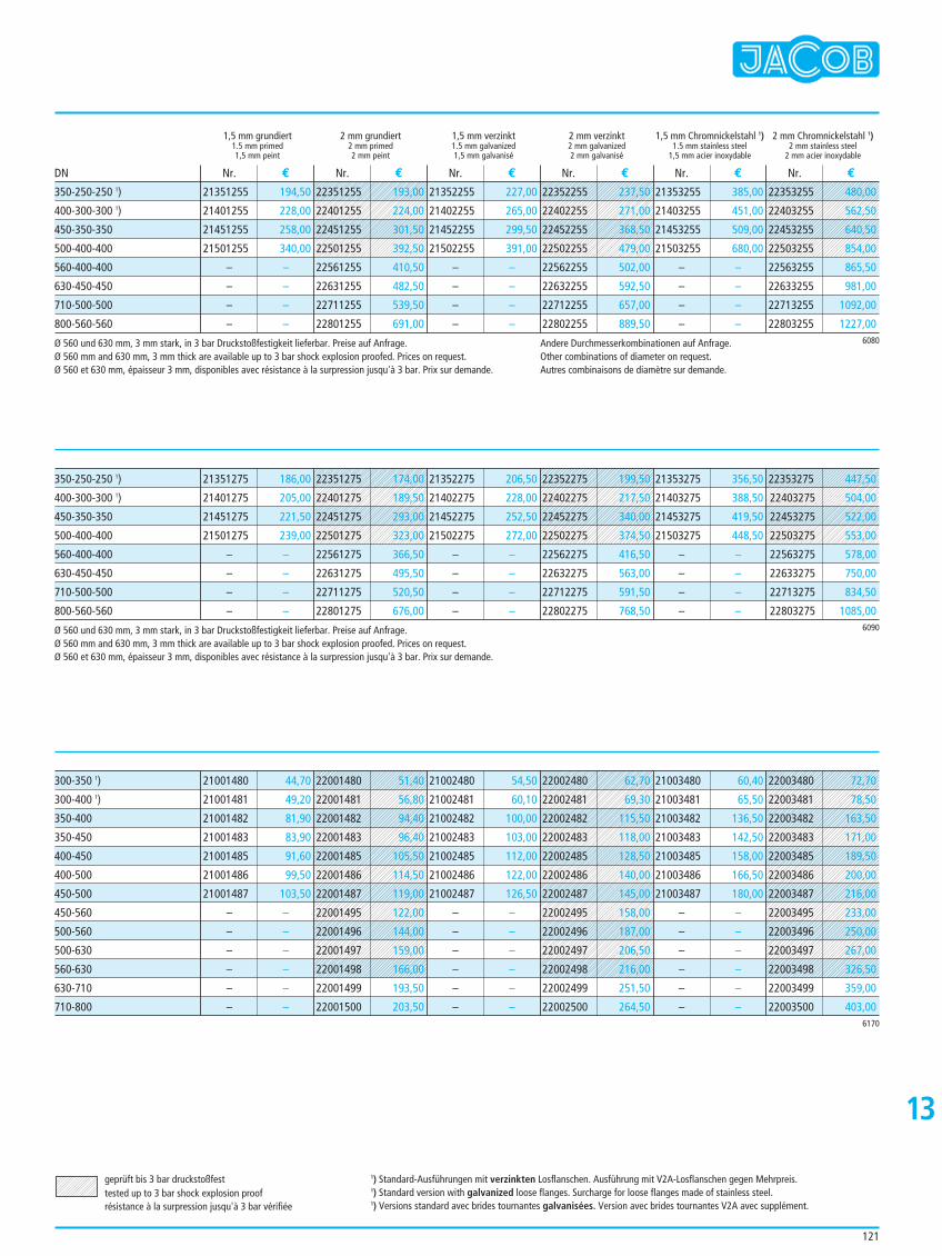
121
1,5 mm grundiert 2 mm grundiert 1,5 mm verzinkt 2 mm verzinkt 1,5 mm Chromnickelstahl 1) 2 mm Chromnickelstahl 1)1.5 mm primed 2 mm primed 1.5 mm galvanized 2 mm galvanized 1.5 mm stainless steel 2 mm stainless steel1,5 mm peint 2 mm peint 1,5 mm galvanisé 2 mm galvanisé 1,5 mm acier inoxydable 2 mm acier inoxydable
21351255 194,50
21401255 228,00
21451255 258,00
21501255 340,00
– –
– –
– –
– –
21352255 227,00
21402255 265,00
21452255 299,50
21502255 391,00
– –
– –
– –
– –
21353255 385,00
21403255 451,00
21453255 509,00
21503255 680,00
– –
– –
– –
– –
Nr. € Nr. € Nr. € Nr. € Nr. € Nr. €DN
350-250-250 1)
400-300-300 1)
450-350-350
500-400-400
560-400-400
630-450-450
710-500-500
800-560-560
Ø 560 und 630 mm, 3 mm stark, in 3 bar Druckstoßfestigkeit lieferbar. Preise auf Anfrage.Ø 560 mm and 630 mm, 3 mm thick are available up to 3 bar shock explosion proofed. Prices on request.Ø 560 et 630 mm, épaisseur 3 mm, disponibles avec résistance à la surpression jusqu'à 3 bar. Prix sur demande.
Andere Durchmesserkombinationen auf Anfrage.Other combinations of diameter on request.Autres combinaisons de diamètre sur demande.
6080
21351275 186,00
21401275 205,00
21451275 221,50
21501275 239,00
– –
– –
– –
– –
21352275 206,50
21402275 228,00
21452275 252,50
21502275 272,00
– –
– –
– –
– –
21353275 356,50
21403275 388,50
21453275 419,50
21503275 448,50
– –
– –
– –
– –
350-250-250 1)
400-300-300 1)
450-350-350
500-400-400
560-400-400
630-450-450
710-500-500
800-560-560
Ø 560 und 630 mm, 3 mm stark, in 3 bar Druckstoßfestigkeit lieferbar. Preise auf Anfrage.Ø 560 mm and 630 mm, 3 mm thick are available up to 3 bar shock explosion proofed. Prices on request.Ø 560 et 630 mm, épaisseur 3 mm, disponibles avec résistance à la surpression jusqu'à 3 bar. Prix sur demande.
6090
21001480 44,70
21001481 49,20
21001482 81,90
21001483 83,90
21001485 91,60
21001486 99,50
21001487 103,50
– –
– –
– –
– –
– –
– –
21002480 54,50
21002481 60,10
21002482 100,00
21002483 103,00
21002485 112,00
21002486 122,00
21002487 126,50
– –
– –
– –
– –
– –
– –
21003480 60,40
21003481 65,50
21003482 136,50
21003483 142,50
21003485 158,00
21003486 166,50
21003487 180,00
– –
– –
– –
– –
– –
– –
300-350 1)
300-400 1)
350-400
350-450
400-450
400-500
450-500
450-560
500-560
500-630
560-630
630-710
710-800
geprüft bis 3 bar druckstoßfesttested up to 3 bar shock explosion proofrésistance à la surpression jusqu'à 3 bar vérifiée
1) Standard-Ausführungen mit verzinkten Losflanschen. Ausführung mit V2A-Losflanschen gegen Mehrpreis.1) Standard version with galvanized loose flanges. Surcharge for loose flanges made of stainless steel.1) Versions standard avec brides tournantes galvanisées. Version avec brides tournantes V2A avec supplément.
6170
13
22351255 193,00
22401255 224,00
22451255 301,50
22501255 392,50
22561255 410,50
22631255 482,50
22711255 539,50
22801255 691,00
22352255 237,50
22402255 271,00
22452255 368,50
22502255 479,00
22562255 502,00
22632255 592,50
22712255 657,00
22802255 889,50
22353255 480,00
22403255 562,50
22453255 640,50
22503255 854,00
22563255 865,50
22633255 981,00
22713255 1092,00
22803255 1227,00
22352275 199,50
22402275 217,50
22452275 340,00
22502275 374,50
22562275 416,50
22632275 563,00
22712275 591,50
22802275 768,50
22351275 174,00
22401275 189,50
22451275 293,00
22501275 323,00
22561275 366,50
22631275 495,50
22711275 520,50
22801275 676,00
22353275 447,50
22403275 504,00
22453275 522,00
22503275 553,00
22563275 578,00
22633275 750,00
22713275 834,50
22803275 1085,00
22003480 72,70
22003481 78,50
22003482 163,50
22003483 171,00
22003485 189,50
22003486 200,00
22003487 216,00
22003495 233,00
22003496 250,00
22003497 267,00
22003498 326,50
22003499 359,00
22003500 403,00
22002480 62,70
22002481 69,30
22002482 115,50
22002483 118,00
22002485 128,50
22002486 140,00
22002487 145,00
22002495 158,00
22002496 187,00
22002497 206,50
22002498 216,00
22002499 251,50
22002500 264,50
22001480 51,40
22001481 56,80
22001482 94,40
22001483 96,40
22001485 105,50
22001486 114,50
22001487 119,00
22001495 122,00
22001496 144,00
22001497 159,00
22001498 166,00
22001499 193,50
22001500 203,50
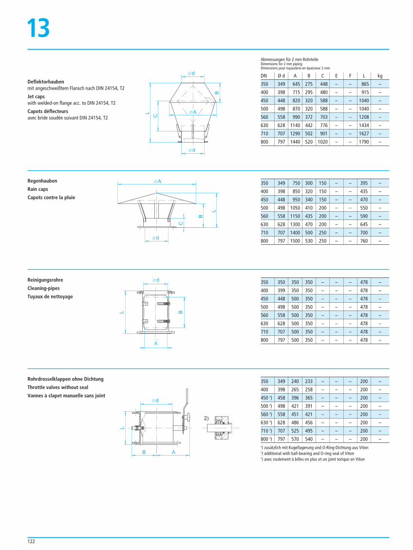
d
B
L
CA
d
BL
A
d
B
L
A
2)
Rohrdrosselklappen ohne Dichtung
Throttle valves without seal
Vannes à clapet manuelle sans joint
350 349 240 233 – – – 200 –
400 398 265 258 – – – 200 –
450 2) 458 396 365 – – – 200 –
500 2) 498 421 391 – – – 200 –
560 2) 558 451 421 – – – 200 –
630 2) 628 486 456 – – – 200 –
710 2) 707 525 495 – – – 200 –
800 2) 797 570 540 – – – 200 –
122
Deflektorhaubenmit angeschweißtem Flansch nach DIN 24154, T2
Jet capswith welded-on flange acc. to DIN 24154, T2
Capots déflecteursavec bride soudée suivant DIN 24154, T2
Regenhauben
Rain caps
Capots contre la pluie
Reinigungsrohre
Cleaning-pipes
Tuyaux de nettoyage
350 349 645 275 448 – – 865 –
400 398 715 295 480 – – 915 –
450 448 820 320 588 – – 1040 –
500 498 870 320 588 – – 1040 –
560 558 990 372 703 – – 1208 –
630 628 1140 442 776 – – 1434 –
710 707 1290 502 901 – – 1627 –
800 797 1440 520 1020 – – 1790 –
Abmessungen für 2 mm RohrteileDimensions for 2 mm pipingDimensions pour tuyauterie en épaisseur 2 mm
DN Ø d A B C E F L kg
350 349 750 300 150 – – 395 –
400 398 850 320 150 – – 435 –
450 448 950 340 150 – – 470 –
500 498 1050 410 200 – – 550 –
560 558 1150 435 200 – – 590 –
630 628 1300 470 200 – – 645 –
710 707 1400 500 250 – – 700 –
800 797 1500 530 250 – – 760 –
350 350 350 350 – – – 478 –
400 399 350 350 – – – 478 –
450 448 500 350 – – – 478 –
500 498 500 350 – – – 478 –
560 558 500 350 – – – 478 –
630 628 500 350 – – – 478 –
710 707 500 350 – – – 478 –
800 797 500 350 – – – 478 –
d
AL
C
d
B
13
2) zusätzlich mit Kugellagerung und O-Ring-Dichtung aus Viton2) additional with ball-bearing and O-ring seal of Viton2) avec roulement à billes en plus et un joint torique en Viton
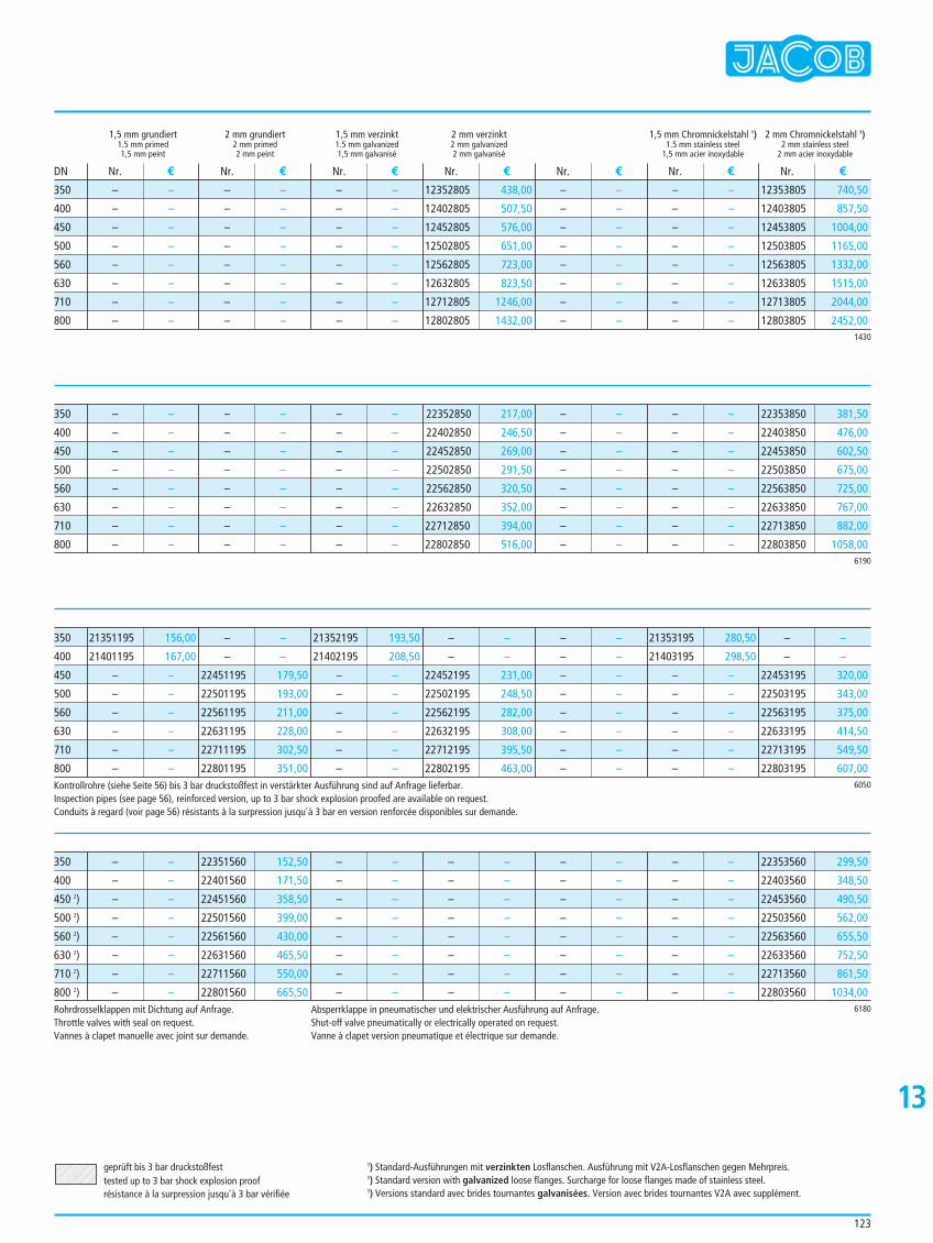
123
1,5 mm grundiert 2 mm grundiert 1,5 mm verzinkt 2 mm verzinkt 1,5 mm Chromnickelstahl 1) 2 mm Chromnickelstahl 1)1.5 mm primed 2 mm primed 1.5 mm galvanized 2 mm galvanized 1.5 mm stainless steel 2 mm stainless steel1,5 mm peint 2 mm peint 1,5 mm galvanisé 2 mm galvanisé 1,5 mm acier inoxydable 2 mm acier inoxydable
– –
– –
– –
– –
– –
– –
– –
– –
– –
– –
– –
– –
– –
– –
– –
– –
– –
– –
– –
– –
– –
– –
– –
– –
12352805 438,00
12402805 507,50
12452805 576,00
12502805 651,00
12562805 723,00
12632805 823,50
12712805 1246,00
12802805 1432,00
– –
– –
– –
– –
– –
– –
– –
– –
– –
– –
– –
– –
– –
– –
– –
– –
12353805 740,50
12403805 857,50
12453805 1004,00
12503805 1165,00
12563805 1332,00
12633805 1515,00
12713805 2044,00
12803805 2452,00
Nr. € Nr. € Nr. € Nr. € Nr. € Nr. € Nr. €DN
1430
350
400
450
500
560
630
710
800
– –
– –
– –
– –
– –
– –
– –
– –
– –
– –
– –
– –
– –
– –
– –
– –
– –
– –
– –
– –
– –
– –
– –
– –
22352850 217,00
22402850 246,50
22452850 269,00
22502850 291,50
22562850 320,50
22632850 352,00
22712850 394,00
22802850 516,00
– –
– –
– –
– –
– –
– –
– –
– –
– –
– –
– –
– –
– –
– –
– –
– –
22353850 381,50
22403850 476,00
22453850 602,50
22503850 675,00
22563850 725,00
22633850 767,00
22713850 882,00
22803850 1058,006190
350
400
450
500
560
630
710
800
21351195 156,00
21401195 167,00
– –
– –
– –
– –
– –
– –
– –
– –
22451195 179,50
22501195 193,00
22561195 211,00
22631195 228,00
22711195 302,50
22801195 351,00
21352195 193,50
21402195 208,50
– –
– –
– –
– –
– –
– –
– –
– –
22452195 231,00
22502195 248,50
22562195 282,00
22632195 308,00
22712195 395,50
22802195 463,00
– –
– –
– –
– –
– –
– –
– –
– –
21353195 280,50
21403195 298,50
– –
– –
– –
– –
– –
– –
– –
– –
22453195 320,00
22503195 343,00
22563195 375,00
22633195 414,50
22713195 549,50
22803195 607,006050
350
400
450
500
560
630
710
800
13
geprüft bis 3 bar druckstoßfesttested up to 3 bar shock explosion proofrésistance à la surpression jusqu'à 3 bar vérifiée
1) Standard-Ausführungen mit verzinkten Losflanschen. Ausführung mit V2A-Losflanschen gegen Mehrpreis.1) Standard version with galvanized loose flanges. Surcharge for loose flanges made of stainless steel.1) Versions standard avec brides tournantes galvanisées. Version avec brides tournantes V2A avec supplément.
Kontrollrohre (siehe Seite 56) bis 3 bar druckstoßfest in verstärkter Ausführung sind auf Anfrage lieferbar.Inspection pipes (see page 56), reinforced version, up to 3 bar shock explosion proofed are available on request.Conduits à regard (voir page 56) résistants à la surpression jusqu'à 3 bar en version renforcée disponibles sur demande.
– –
– –
– –
– –
– –
– –
– –
– –
22351560 152,50
22401560 171,50
22451560 358,50
22501560 399,00
22561560 430,00
22631560 465,50
22711560 550,00
22801560 665,50
– –
– –
– –
– –
– –
– –
– –
– –
– –
– –
– –
– –
– –
– –
– –
– –
– –
– –
– –
– –
– –
– –
– –
– –
– –
– –
– –
– –
– –
– –
– –
– –
22353560 299,50
22403560 348,50
22453560 490,50
22503560 562,00
22563560 655,50
22633560 752,50
22713560 861,50
22803560 1034,006180
350
400
450 2)
500 2)
560 2)
630 2)
710 2)
800 2)Rohrdrosselklappen mit Dichtung auf Anfrage.Throttle valves with seal on request.Vannes à clapet manuelle avec joint sur demande.
Absperrklappe in pneumatischer und elektrischer Ausführung auf Anfrage.Shut-off valve pneumatically or electrically operated on request.Vanne à clapet version pneumatique et électrique sur demande.
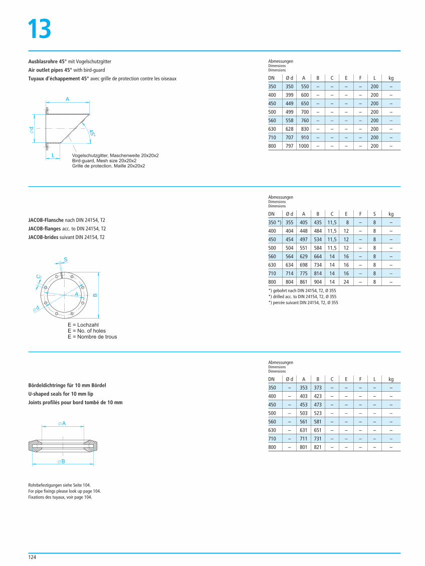
124
Ausblasrohre 45° mit Vogelschutzgitter
Air outlet pipes 45° with bird-guard
Tuyaux d’échappement 45° avec grille de protection contre les oiseaux
JACOB-Flansche nach DIN 24154, T2
JACOB-flanges acc. to DIN 24154, T2
JACOB-brides suivant DIN 24154, T2
Bördeldichtringe für 10 mm Bördel
U-shaped seals for 10 mm lip
Joints profilés pour bord tombé de 10 mm
350 350 550 – – – – 200 –
400 399 600 – – – – 200 –
450 449 650 – – – – 200 –
500 499 700 – – – – 200 –
560 558 760 – – – – 200 –
630 628 830 – – – – 200 –
710 707 910 – – – – 200 –
800 797 1000 – – – – 200 –
AbmessungenDimensionsDimensions
AbmessungenDimensionsDimensions
DN Ø d A B C E F L kg
DN Ø d A B C E F L kg
350 *) 355 405 435 11,5 8 – 8 –
400 404 448 484 11,5 12 – 8 –
450 454 497 534 11,5 12 – 8 –
500 504 551 584 11,5 12 – 8 –
560 564 629 664 14 16 – 8 –
630 634 698 734 14 16 – 8 –
710 714 775 814 14 16 – 8 –
800 804 861 904 14 24 – 8 –
AbmessungenDimensionsDimensions
DN Ø d A B C E F S kg
350 – 353 373 – – – – –
400 – 403 423 – – – – –
450 – 453 473 – – – – –
500 – 503 523 – – – – –
560 – 561 581 – – – – –
630 – 631 651 – – – – –
710 – 711 731 – – – – –
800 – 801 821 – – – – –
Rohrbefestigungen siehe Seite 104.For pipe fixings please look up page 104.Fixations des tuyaux, voir page 104.
*) gebohrt nach DIN 24154, T2, Ø 355*) drilled acc. to DIN 24154, T2, Ø 355*) percée suivant DIN 24154, T2, Ø 355
d
L
A
45°
Vogelschutzgitter, Maschenweite 20x20x2
Bird-guard, Mesh size 20x20x2
Grille de protection, Maille 20x20x2
13
BA
S
C
d
E = Lochzahl
E = No. of holes
E = Nombre de trous
A
B
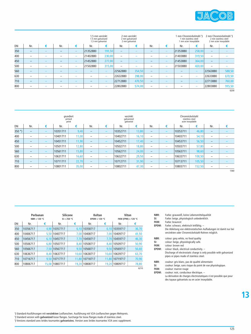
125
1,5 mm verzinkt 2 mm verzinkt 1 mm Chromnickelstahl 1) 2 mm Chromnickelstahl 1)1.5 mm galvanized 2 mm galvanized 1 mm stainless steel 2 mm stainless steel1,5 mm galvanisé 2 mm galvanisé 1 mm acier inoxydable 2 mm acier inoxydable
– –
– –
– –
– –
– –
– –
– –
– –
– –
– –
– –
– –
– –
– –
– –
– –
21352880 191,50
21402880 230,00
21452880 277,00
21502880 315,00
– –
– –
– –
– –
– –
– –
– –
– –
22562880 354,50
22632880 398,00
22712880 470,50
22802880 574,00
– –
– –
– –
– –
– –
– –
– –
– –
21353880 258,00
21403880 319,50
21453880 364,00
21503880 420,00
– –
– –
– –
– –
– –
– –
– –
– –
22563880 588,50
22633880 670,50
22713880 760,00
22803880 915,50
Nr. € Nr. € Nr. € Nr. € Nr. € Nr. € Nr. €DN
6200
350
400
450
500
560
630
710
800
grundiert verzinkt Chromnickelstahlprimed galvanized stainless steelpeint galvanisé acier inoxydable
– –
– –
– –
– –
– –
– –
– –
– –
10351711 9,40
10401711 11,00
10451711 11,90
10501711 12,80
10561711 15,80
10631711 16,60
10711711 22,70
10801711 35,00
– –
– –
– –
– –
– –
– –
– –
– –
10352711 13,80
10402711 16,10
10452711 17,40
10502711 18,80
10562711 24,00
10632711 29,50
10712711 31,90
10802711 47,30
– –
– –
– –
– –
– –
– –
– –
– –
10353711 46,80
10403711 54,10
10453711 56,50
10503711 57,80
10563711 98,60
10633711 100,50
10713711 105,50
10803711 152,50
– –
– –
– –
– –
– –
– –
– –
– –
Nr. € Nr. € Nr. € Nr. € Nr. € Nr. € Nr. €DN
1360
350 *)
400
450
500
560
630
710
800
13
1) Standard-Ausführungen mit verzinkten Losflanschen. Ausführung mit V2A-Losflanschen gegen Mehrpreis.1) Standard version with galvanized loose flanges. Surcharge for loose flanges made of stainless steel.1) Versions standard avec brides tournantes galvanisées. Version avec brides tournantes V2A avec supplément.
10356717 4,90
10406717 5,50
10456717 6,10
10506717 6,80
10566717 7,50
10636717 8,40
10716717 9,50
10806717 15,00
10357717 6,10
10407717 7,00
10457717 7,70
10507717 8,40
10567717 9,50
10637717 10,60
10717717 11,80
10807717 19,20
10358717 6,10
10408717 7,00
10458717 7,70
10508717 8,40
10568717 9,50
10638717 10,60
10718717 11,80
10808717 19,20
10359717 36,70
10409717 41,50
10459717 46,30
10509717 50,90
10569717 56,60
10639717 63,70
10719717 70,90
10809717 78,80
Nr. € Nr. € Nr. € Nr. €DN
6210
350
400
450
500
560
630
710
800
Perbunan Silicone Keltan VitonNBR ≤ 120 °C SI ≤ 250 °C EPDM ≤ 120 °C FKM (FPM) ≤ 120 °C
NBR: Farbe: grauweiß, keine LebensmittelqualitätSI: Farbe: beige, physiologisch unbedenklich.FKM: Farbe: braunrotEPDM: Farbe: schwarz, elektrisch leitfähig. –
Die Ableitung von elektrostatischen Aufladungen ist damit nur beiverzinkten oder Chromnickelstahl-Rohren möglich.
NBR: colour: grey white, no food qualitySI: colour: beige, physiologically safe.FKM: colour: brown redEPDM: colour: black, electrical conductivity. –
Discharge of electrostatic charge is only possible with galvanizedpipes or pipes made of stainless steel.
NBR: couleur: gris blanc, pas de qualité alimentaireSI: couleur: beige, sans risque du point de vue physiologique.FKM: couleur: marron rougeEPDM: couleur: noir, conducteur électrique. –
La dérivation de charges électrostatiques n'est possible que pourdes tuyaux galvanisés ou en acier inoxydable.
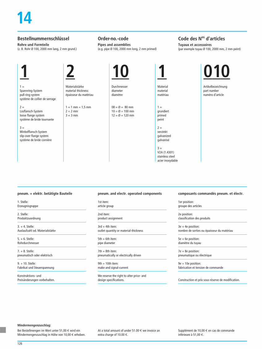
126
pneum. + elektr. betätigte Bauteile
1. Stelle:Erzeugnisgruppe
2. Stelle:Produktzuordnung
3. + 4. Stelle:Auslaufzahl od. Materialstärke
5. + 6. Stelle:Rohrdurchmesser
7. + 8. Stelle:pneumatisch oder elektrisch
9. + 10. Stelle:Fabrikat und Steuerspannung
Konstruktions- und Preisänderungen vorbehalten.
14
Mindermengenzuschlag:
Bei Bestellmengen im Wert unter 51,00 € wird einMindermengenzuschlag in Höhe von 10,00 € erhoben.
At a total amount of under 51.00 € we invoice anextra charge of 10.00 €.
Supplément de 10,00 € en cas de commandeinférieure à 51,00 €.
pneum. and electr. operated components
1st item:article group
2nd item:product assignment
3rd + 4th item:outlet quantity or material-thickness
5th + 6th item:pipe diameter
7th + 8th item:pneumatically or electrically driven
9th + 10th item:make and signal-current
We reserve the right to alter price- anddesign specifications.
composants commandés pneum. et électr.
1er position:groupe des articles
2e position:classification des produits
3e + 4e position:nombre de sorties ou épaisseur du matériau
5e + 6e position:diamètre du tuyau
7e + 8e position:pneumatique ou électrique
9e + 10e position:fabrication et tension de commande
Construction et prix sous réserve de modification.
BestellnummernschlüsselRohre und Formteile(z. B. Rohr Ø 100, 2000 mm lang, 2 mm grund.)
Order-no.-codePipes and assemblies(e.g. pipe Ø 100, 2000 mm long, 2 mm primed)
Code des Nos d’articlesTuyaux et accessoires(par exemple tuyau Ø 100, 2000 mm, 2 mm peint)
11 =Spannring-Systempull-ring systemsystème de collier de serrage
2 =Losflansch-Systemloose flange systemsystème de bride tournante
3 =Winkelflansch-Systemslip-over flange systemsystème de bride cornière
2Materialstärkematerial thicknessépaisseur du matériau
1 = 1 mm + 1,5 mm2 = 2 mm3 = 3 mm
10Durchmesserdiameterdiamètre
08 = Ø = 80 mm10 = Ø = 100 mm12 = Ø = 120 mm
1Materialmaterialmatériau
1 = grundiertprimedpeint
2 =verzinktgalvanizedgalvanisé
3 =V2A (1.4301)stainless steelacier inoxydable
010Artikelbezeichnungpart numbernuméro d’article
Allgemeine Lieferungs- und Zahlungsbedingungen
127
14
I. Vertragsabschluss und Umfang der Lieferung
1. Die in den Angeboten angegebenen Leistungsmerkmale sowie Abbildungen, Zeichnungen,Gewichts- und Maßangaben sind nur als annähernd zu betrachten. Unwesentliche und/oderhandelsübliche Abweichungen, die die Verwendbarkeit nicht beeinträchtigen und dem Käuferzumutbar sind, bleiben vorbehalten. An unseren Unterlagen, wie z. B. Kostenvoranschlägen oderZeichnungen behalten wir uns das Eigentums- und Urheberrecht vor. Sie dürfen Dritten nur mitunserem Einverständnis zugänglich gemacht werden. Vom Besteller als vertraulich bezeichneteUnterlagen dürfen wir nur mit dessen Zustimmung Dritten zugänglich machen.
2. Bestellungen sind für uns erst verbindlich, wenn wir sie schriftlich bestätigt haben. Fehlt eineschriftliche Bestätigung, gilt die erteilte Rechnung als Auftragsbestätigung. Maßgebend für denUmfang der Lieferung ist die schriftliche Auftragsbestätigung. Liegt diese nicht vor, bestimmt sichder Lieferumfang nach demjenigen Angebot, welches vom Besteller fristgerecht angenommenwurde. Etwaige Nebenabreden und Änderungen bedürfen der Schriftform.
II. Preise und Zahlungen
1. Die Preise gelten ab Werk einschließlich Verladung im Werk, jedoch ausschließlich Verpackung. Esgelten die am Tag der Bestellung gültigen Preise. Diese verstehen sich in EUR ohne Mehrwert-steuer, welche in gesetzlicher Höhe am Tag der Rechnungsstellung in der Rechnung gesondertausgewiesen wird. Die Zahlung ist bar ohne jeden Abzug frei Zahlstelle des Lieferers zu leisten,und zwar: 1/3 Anzahlung nach Eingang der Auftragsbestätigung, 1/3 bei Mitteilung der Versand-bereitschaft der Hauptteile an den Besteller, der Restbetrag innerhalb von 30 Tagen nach Fälligkeitund Zugang einer Rechnung.
2. Bei schuldhafter Überschreitung der Zahlungsfrist verlangen wir Verzugszinsen in Höhe von 8 %über dem jeweils geltenden Basiszinssatz nach § 247 BGB. Kommt der Besteller mit einem nichtunerheblichen Teil der Zahlung in Verzug oder gehen seine Schecks oder Wechsel zu Protest oderentfallen die Voraussetzungen für eine Kreditgewährung, so werden unsere sämtlichen Forde-rungen gegen ihn zur sofortigen Zahlung fällig. Dies gilt auch für ursprünglich gestundete Rech-nungen sowie später fällige Wechsel oder Schecks.
3. Verschlechtert sich die Vermögenslage des Bestellers nach Vertragsschluss erheblich oder wird dieschlechte Vermögenslage erst nach Vertragsschluss erkennbar, so sind wir im Fall der Gefährdungder Gegenleistung berechtigt, noch nicht ausgeführte Lieferungen zu verweigern bzw. ange-messene Vorauszahlungen oder Sicherheitsleistungen zu verlangen.
4. Der Besteller kann nur dann aufrechnen, wenn dessen Gegenforderung unbestritten ist oder einrechtskräftiger Titel vorliegt. Ein Zurückbehaltungsrecht kann nur geltend gemacht werden, soweites auf Ansprüchen aus demselben Vertragsverhältnis beruht.
III. Lieferung
1. Verbindliche Lieferfristen können nur schriftlich vereinbart werden. Ist im Vertrag nichts anderesvereinbart, beginnen die Lieferfristen mit Vertragsschluss.
2. Sofern wir betroffen sind von Maßnahmen im Rahmen von Arbeitskämpfen, insbesondere Streikund Aussperrung sowie bei Eintritt unvorhergesehener Ereignisse, die außerhalb unseres Willensliegen, z. B. Verkehrs- und Betriebsstörungen, Werkstoff – oder Energiemangel, Lieferverzögerungeines Vorlieferanten, etc., verlängert sich die Lieferfrist angemessen. Verzögert oder unterlässt derBesteller seinerseits erforderliche oder vereinbarte Mitwirkungshandlungen, verlängert sich dieLieferfrist ebenfalls angemessen. Dasselbe gilt bei vom Besteller veranlassten Änderungen der zuliefernden Ware.
3. Bei einem Leistungsaufschub von mehr als 4 Monaten aufgrund der vorgenannten, nicht in unsererSphäre liegenden Gründe, können wir vom Vertrag zurücktreten. Andere Rücktrittsrechte bleibenunberührt.
4. Verzögert sich der Versand auf Wunsch des Bestellers, so werden ihm, beginnend einen Monatnach unserer Anzeige der Versandbereitschaft, die durch die Lagerungen entstehenden Kosten, beiLagerungen im Werk des Lieferers mindestens 1/2 von v. H. des Rechnungsbetrages für jedenMonat berechnet.
5. Soweit Teillieferungen dem Käufer zumutbar sind, bleiben diese vorbehalten.
6. Die Versandart steht in unserem Ermessen. Es besteht keine Verpflichtung, den billigsten Versandzu wählen.
IV. Gefahrübergang
Die Gefahr der zufälligen Verschlechterung und des zufälligen Untergangs der Sache geht auf denBesteller über, sobald wir die Sache der zur Ausführung der Versendung bestimmten Person ausge-liefert haben. Dies gilt unabhängig von der Frage der Übernahme der Versandkosten oder der Anfuhrund Aufstellung. Auf Wunsch des Bestellers versichern wir die Sendung auf seine Kosten gegenDiebstahl, Bruch-, Transport-, Feuer-, und Wasserschäden sowie sonstige versicherbare Risiken.
V. Eigentumsvorbehalt
1. Alle gelieferten Waren bleiben unser Eigentum bis zur Erfüllung sämtlicher, auch künftiger undbedingter Forderungen aus der Geschäftsbeziehung. Dies gilt auch, wenn Zahlungen auf beson-ders bezeichnete Forderungen geleistet werden. Der Besteller ist berechtigt, den Liefergegenstandim ordnungsgemäßen Geschäftsgang weiter zu veräußern, wobei er seine Forderungen aus derWeiterveräußerung hiermit an uns abtritt und wir die Abtretung annehmen. Zur Einziehung dieserForderungen bleibt der Besteller auch nach der Abtretung ermächtigt. Unsere Befugnis, die For-derungen selbst einzuziehen, bleibt hiervon unberührt. Solange der Besteller seine uns gegenüberbestehenden Zahlungsverpflichtungen vertragsgemäß nachkommt, werden wir die Forderungen
nicht selbst einziehen. Kommt der Besteller seinen Vertragspflichten nicht ordnungsgemäß nach,kann die Befugnis zur Weiterveräußerung von uns widerrufen werden.
2. Be- oder verarbeitet der Besteller die Ware, erstreckt sich der Eigentumsvorbehalt auch auf diegesamte neue Sache. Zu dem Bruchteil, der dem Verhältnis des Wertes seiner Ware zu dem der vonuns gelieferten Waren, erwirbt der Besteller Miteigentum. Übersteigt der Wert der uns zustehen-den Sicherheiten die zu sichernden Forderungen um mehr als 10 %, sind wir verpflichtet, die demBesteller zustehenden Sicherheiten auf Verlangen insoweit freizugeben. Bezüglich der freizu-gebenden Sicherheiten obliegt uns die freie Auswahl.
3. Der Besteller darf den Liefergegenstand weder verpfänden noch zur Sicherheit übereignen. BeiPfändung sowie Beschlagnahme oder sonstigen Verfügungen durch dritte Hand sind wir un-verzüglich davon zu benachrichtigen.
VI. Sachmängelhaftung
1. Beim Verkauf neu hergestellter Sachen beträgt die Verjährungsfrist für Sachmängel 1 Jahr; der -Verkauf gebrauchter Waren erfolgt unter Ausschluss jeglicher Sachmängelhaftung. Dies gilt nur,sofern es sich beim Besteller nicht um einen Verbraucher handelt. Liegt ein Mangel vor, kann derBesteller zunächst Nacherfüllung gem. § 439 BGB verlangen. Wir können zwischen der Besei-tigung des Mangels und der Lieferung einer mangelfreien Sache wählen, wenn der Besteller keinVerbraucher ist. Mängelansprüche des kaufmännischen Bestellers kommen nur in Betracht, wenndieser den Untersuchungs- und Rügeobliegenheiten gem. § 377 HGB bezüglich jeglicher Ab-weichungen nachgekommen ist. Innerhalb einer Frist von 10 Werktagen müssen Beanstandungenbei uns eingehen. Verborgene Mängel sind unverzüglich nach ihrer Entdeckung mitzuteilen. Ande-renfalls gilt die gelieferte Ware als genehmigt.
2. Hat der Besteller die von uns gelieferte Ware montiert, bevor Mängelansprüche geltend gemachtwerden, so haften wir nur, wenn die Montage bzw. der Einbau der verkauften Sache vom Bestel-ler fachkundig durchgeführt wurde. Der Besteller trägt hierfür die Darlegungs- und Beweislast.
3. Sofern der Besteller Schadensersatzansprüche geltend macht, die auf Arglist, Vorsatz oder groberFahrlässigkeit beruhen, haften wir nach den gesetzlichen Bestimmungen. Wird uns keine vorsätz-liche Vertragsverletzung angelastet, haften wir nur auf den Ersatz des typischen vorhersehbarenSchadens. Darüber hinaus ist ein Anspruch auf Schadensersatz des Bestellers ausgeschlossen.Insbesondere scheidet eine Haftung für Schäden, die nicht am Liefergegenstand entstanden sind,aus, es sei denn, es handelt sich um Schäden aus der Verletzung des Lebens, des Körpers oder derGesundheit, die auf einer von uns begangenen fahrlässigen Pflichtverletzung oder einer vorsätz-lichen oder fahrlässigen Pflichtverletzung unseres gesetzlichen Vertreters oder Erfüllungsgehilfenberuhen.
VII. Rückgriff des Unternehmers
Verkauft der Besteller die neu hergestellte Ware im Rahmen seines gewerblichen Betriebes an einenVerbraucher weiter und musste er diese Ware als Folge ihrer Mangelhaftigkeit zurücknehmen oderminderte der Verbraucher den Kaufpreis, so bedarf es für die Geltendmachung der Mängelansprüchedes Bestellers uns gegenüber keiner Fristsetzung. Der Besteller kann in dem Fall von uns Ersatz derAufwendungen verlangen, die er im Verhältnis zum Verbraucher zu tragen hatte, wenn der vom Ver-braucher geltend gemachte Mangel bereits bei Übergang der Gefahr auf den Besteller vorhandenwar. Im Rahmen dieses Unternehmerrückgriffs hat der Besteller keinen Anspruch auf Schadensersatz.
VIII. Schlussbestimmungen
1. Ist der Besteller Kaufmann, juristische Person des öffentlichen Rechts oder ein öffentlich-recht-liches Sondervermögen, ist Gerichtsstand für alle sich aus dem Vertragsverhältnis ergebendenStreitigkeiten einschließlich Scheck-, Wechsel- und Urkundenprozessen der Gerichtsort, der für un-seren Firmensitz oder den die Lieferung ausführende Niederlassung zuständig ist. Erfüllungsort istPorta Westfalica.
2. Auf alle Verträge findet deutsches Recht Anwendung.
3. Sämtliche Lieferungen und Leistungen erfolgen unter Zugrundelegung der vorgenannten Bedin-gungen. Anders lautende Bedingungen, Abweichungen oder mündliche Nebenabreden sind füruns nur verbindlich, wenn diese ausdrücklich bestätigt worden sind oder soweit sie zwingendemRecht entsprechen.
4. Sollten einzelne Bestimmungen dieser Lieferungs- und Zahlungsbedingungen unwirksam sein, sowird die Wirksamkeit der übrigen Bestimmungen davon nicht berührt. Gemeinsam mit demBesteller werden wir etwaige unwirksame Bestimmungen im Rahmen des Zumutbaren nach Treuund Glauben durch solche Regelungen ersetzten, die dem wirtschaftlichen Zweck des Vertragesam besten gerecht werden, ohne dass dadurch eine wesentliche Änderung des Vertragsinhaltserfolgt. Das Gleiche gilt, falls es an einer ausdrücklichen Regelung eines regelungsbedürftigenSachverhalts fehlt.
Stand Juli 2002
128
14
I. Conclusion of Contract and Scope of Delivery
1. The performance features as well as pictures, drawings, weights and dimensions given in theoffers are approximate only. Minor deviations, and/or deviations usual in the trade, which do notadversely affect usability and are not unreasonable for the Customer, are acceptable. We retainthe title and copyrights to any and all of our documents, such as price estimates or drawings. Saiddocuments may be disclosed to third parties only with our approval. We may disclose to third par-ties documents designated by the Customer as confidential only with the approval of the latter.
2. Orders shall not be binding for us until we have confirmed them in writing. If no written confirma-tion has been given, the issued invoice shall be deemed the order confirmation. The written orderconfirmation is decisive for the scope of the delivery. If there is no written confirmation, the scopeof the delivery shall be determined according to the offer which was accepted by the Customer indue time. Subsidiary agreements and modifications must be made in writing in order to beeffective.
II. Prices and Payments
1. Prices are given ex works, including loading in the works, but excluding packaging. Prices valid onthe day of the order shall apply. Prices are given in euros and without value-added tax, which willbe applied at the current rate on the day of the issue of the invoice and itemized separately on theinvoice. Payment shall be made in cash without any deductions, free payment agent of the-supplier, as follows: 1/3 advance payment upon receipt of the order confirmation, 1/3 upon
notification of readiness of shipping of the major parts to the Customer, the balance within 30days after due date and receipt of an invoice.
2. In the event the payment deadline is exceeded for culpable cause, we will charge default interestin the amount of 8% above the current basic interest rate in accordance with Section 247 BGB(Civil Code). If the Customer is in default for a substantial part of the payment, or if his cheques orbills of exchange are protested, or if the conditions for granting a credit line cease to exist, any andall of our receivables due from the Customer shall become due and payable immediately. Theabove provision shall also apply to invoices which have been deferred as well as to bills of exchan-ge or cheques which become payable at a later time.
3. If there is a substantial worsening of the Customer’s assets after conclusion of the contract, or ifthe poor asset situation does not become recognizable until after conclusion of the contract, weare entitled, in the event of a threat to counter-performance, to refuse any performances not yetcarried out, or to request reasonable advance payments or collateral.
4. The Customer may set off any counter-claims only if and when said claims are undisputed or a-legally final title has been granted. A right of retention may be asserted only to the extent that it
applies to claims from the same contractual relationship.
III. Delivery
1. Delivery dates will be binding only if and when agreed in writing. In the absence of deviatingcontractual provisions, the delivery periods will begin upon conclusion of the contract.
2. To the extent that we are affected by measures of industrial action, in particular strikes and lock-outs, or by the occurrence of unforeseen events which are beyond our influence, e.g., traffic andoperational disruptions, material or energy shortages, default in delivery by a pre-supplier, etc.,the delivery period shall be extended by a reasonable time. If the Customer on his part delays, orfails to carry out, the required or agreed cooperation actions, the delivery period shall also beextended by a reasonable period. The above provision shall also apply if the Customer requireschanges in the goods which are to be delivered.
3. In the event performance is postponed by more than 4 months due to the above-mentionedreasons which are beyond our influence, we may cancel the contract. The above provision iswithout prejudice for further rights of withdrawal.
4. If dispatch is delayed at the request of the Customer, he shall be invoiced for costs incurred forstorage – for storage at the supplier’s works, no less than 0.5% of the amount of the invoice foreach month – beginning one month after we have given notification of readiness for dispatch.
5. We reserve the right to make partial deliveries to the extent that said deliveries are reasonable forthe Customer.
6. The type of shipment shall be at our discretion. We are not obligated to choose the least expensivetype of shipment.
IV. Transfer of Risk
The risk of accidental worsening or accidental loss of the object shall be transferred to the Customeras soon as we have surrendered the object to the person designated to carry out the shipment. Theabove provision shall apply regardless of the question of the assumption of shipping costs or ofdelivery to the location and installation. At the request of the Customer, we will insure the consign-ment, at his expense, for theft, breakage, transport, fire and water damage as well as for otherinsurable risks.
V. Retention of Title
1. Any and all delivered good shall remain our property until any and all claims from the businessrelationship, including future and contingent claims, have been fulfilled. The above provision shallalso apply if payments have been on specially designated claims. The Customer is entitled to sellfurther the object of the delivery in the course of his ordinary business; he hereby assigns to us hisclaims from the further sale, and we hereby accept the assignment. The Customer remains entitledto collect said claims, even following the assignment. The above provision is without prejudice for
our authority to collect the claims ourselves. As long as the Customer fulfils his paymentobligations to us in accordance with the contract, we will not collect the claims ourselves. If theCustomer does not fulfil his contractual obligations in an orderly manner, we may revoke the aut-horization to sell the goods further.
2. If the Customer processes or works the goods, the retention of title shall also apply to the newobject as a whole. The Customer shall acquire co-ownership to the object in the same fraction asthe ratio of the value of his goods to the value of the goods we have delivered. If the value of thecollateral to which we are entitled exceeds the claims being secured by more than 10%, we areobligated to release, upon request, the collateral to which the Customer is entitled in the amountof the excess. The selection of the collateral to be released shall be at our discretion.
3. The Buyer may neither pledge nor assign as security the object of the delivery. In the event ofattachment or confiscation or other intervention by third parties, we shall be notified immediately.
VI. Liability for Defects
1. The period of limitations for defects in the object is 1 year for the sale of newly manufacturedobjects; the sale of used goods shall be effected excluding any and every form of liability fordefects. The above provision shall apply to the extent that the Customer is not a consumer. If thereis a defect, the Customer may first demand subsequent performance in accordance with Section439 BGB. If the Customer is not a consumer, we may choose between elimination of the defect andthe delivery of an object free of defects. Claims due to defects of a business customer are possibleonly if and when said Customer has fulfilled his inspection and complaint obligations in accor-dance with Section 377 HGB (Commercial Code) regarding each and every deviation. We musthave received complaints within a period of 10 working days. Notification of hidden defects mustbe submitted immediately upon discovery of said defects. In all other cases, the delivered goodsshall be deemed accepted.
2. If the Customer installs the goods we have delivered before claims due to defects are asserted, weare liable only if the installation or assembly of the sold goods has been properly carried out by theCustomer. The Customer bears the burden of presentation and proof in such cases.
3. To the extent that the Customer asserts damage compensation claims on the basis of fraudulentmisrepresentation, intention or gross negligence, we shall be liable in accordance with legalstatutory provisions. If we are not charged with intentional infringement of the contract, we shallbe liable only for compensation of damage which is typically foreseeable. Any and all furtherclaims of the Customer for damage compensation shall be excluded. In particular, liability fordamage not occurring to the object of the delivery is excluded, unless it is a question of damageconsequent to injury to life, body or health resulting from violation of an obligation we have cau-sed by negligence, or a violation of an obligation caused by our legal representative or vicariousagent intentionally or by negligence.
VII. Recourse of the Customer
If the Customer sells further to a consumer the newly manufactured goods in the course of hiscommercial operations, and if he has had to accept return of these goods due to defects in saidgoods, or if the consumer has reduced the purchase price, the assertion of claims due to defects onthe part of the Customer against us does not require the setting of a time period.
In this case, the Customer may demand from us reimbursement of the expenditures which he had tobear in his relationship to the consumer if the defects asserted by the consumer existed at the time atwhich the risk was transferred to the Customer. The Customer shall have no claim for damagecompensation within the scope of this customer recourse.
VIII. Final Provisions
1. If the Customer is a business person, legal person under public law or a special fund under publiclaw, jurisdiction for any and all disputes resulting from the contractual relationship, includingcheque, bills of exchange and legal document litigation, shall be the courts at our registered placeof business or at the place of business of the branch office carrying out the performance. Place ofperformance is Porta Westfalica.
2. Any and all contracts are governed by German law.
3. Any and all deliveries and services are performed on the basis of the above terms and conditions.Contrary terms and conditions, deviations or oral subsidiary agreements shall be binding on usonly if and when they have been expressly confirmed, or to the extent that they correspond tocompulsory law.
4. If individual provisions of these general terms and conditions of delivery and payment are invalid,the validity of the remaining provisions shall not be affected thereby. We shall, in cooperation withthe Customer, replace any invalid provisions, within reason and in good faith, by regulations whichare closest in intention to the commercial purpose of the contract, without causing thereby asubstantial change in the content of the contract. The above provision shall apply if there is noexpress regulation for a situation requiring regulation.
Last revised 2002
General Terms and Conditions of Delivery and Payment
129
14
I. Conclusion du contrat et étendue de la livraison
1. Les caractéristiques indiquées dans les offres ainsi que les photos, dessins, indications de poids etde dimensions sont à considérer comme étant seulement approximatifs. Nous nous réservons ledroit d'écarts mineurs et/ou habituels dans le commerce, qui ne compromettent pas l'utilisation etqui sont tolérables pour l'acheteur. Nous nous réservons le droit de propriété et d'auteur pour nosdocuments tels que devis et dessins. Il est interdit de les communiquer à des tiers sans notreaccord. Nous ne sommes pas autorisés à communiquer des documents confiés par le donneur-d'ordre et désignés comme étant confidentiels à des tiers sans son autorisation.
2. Nous ne considérons une commande comme contractuelle que si nous l'avons confirmée par écrit.En cas d'absence d'accusé de réception de commande écrit, la facture émise fait office deconfirmation de commande. L'étendue de la livraison est déterminée par la confirmation decommande écrite. En cas d'absence de ce document, son étendue s'oriente à celle des offres qui aété acceptée par le donneur d'ordre dans les délais. Tout accord annexe ou avenant requiert la for-me écrite.
II. Prix et paiements
1. Nos prix s'entendent départ usine y compris chargement à l'usine, mais hors emballage. Les prixappliqués sont ceux qui étaient en vigueur le jour de la commande. Ils s'entendent en EUR horstaxe, la TVA en sus au taux légal en vigueur au jour de l'émission de la facture étant notée de façondistincte sur la facture. Le paiement doit se faire comptant, sans retenue aucune, auprès de l'or-ganisme payeur du fournisseur, à savoir: 1/3 d'acompte à la réception de la confirmation decommande, 1/3 lors de la notification de la mise à disposition des pièces principales au donneurd'ordre, le solde dans les 30 jours après échéance et réception de la facture.
2. En cas du dépassement fautif du délai de paiement, outre l’intérêt légal une pénalité égale à 3 foiscet intérêt légal sera appliquée (loi N° 921442 du 31. 12. 1992). Au cas où le donneur d'ordre esten retard de paiement pour une fraction non négligeable du montant, si ses chèques ou traites fontl'objet d'un rejet par la banque ou si les conditions permettant d'accorder un crédit ne sont plusremplies, toutes nos créances deviennent exigibles immédiatement. Ceci vaut également pour desfactures ayant fait initialement l'objet d'un délai de paiement ou pour des traites ou chèques exi-gibles ultérieurement.
3. Si la situation économique du donneur d'ordre devait se dégrader nettement après la conclusiondu contrat ou si la mauvaise situation économique n'a pu être découverte qu'après la conclusiondu contrat, nous sommes autorisés, dans le cadre du risque dont fait l'objet la contrepartie, àrefuser des livraisons non encore exécutées ou de réclamer des paiements d'avance ou des garan-ties adaptés.
4. Le donneur d'ordre n'est autorisé à régler par compensation que si sa créance est incontestée ous'il dispose d'un titre juridiquement valable. Un droit à retenue ne peut s'appliquer que dans lamesure où il repose sur des droits nés du même contrat.
III. Livraison
1. Des délais fermes de livraison doivent être convenus par écrit. Sauf convention contractuelledifférente, les délais de livraison commencent à la conclusion du contrat.
2. Si nous devions être concernés par des mesures dans le cadre de conflits de travail, notammentgrève et lock-out, ou en cas de survenance d'événements imprévisibles indépendants de notrevolonté, par ex. perturbations de transport ou d'exploitation, manque de matériaux ou d'énergies,retard de livraison d'un de nos fournisseurs en amont etc., le délai de livraison se prolonge dansune mesure appropriée. Si le donneur d'ordre de son côté n'exécute pas les actions de coopérati-on nécessaires ou convenues, le délai de livraison se prolonge également dans une mesureappropriée. La même chose s'applique en cas de modifications sur la marchandise à livrer qui ontété demandées par le donneur d'ordre.
3. Dans le cas d'un retard de livraison supérieur à 4 mois pour des raisons précitées et qui nous sontextérieures, nous sommes autorisés à résilier le contrat. Ceci n'affecte pas nos autres droits àrésiliation.
4. Si la livraison est retardée à la demande du donneur d'ordre, nous lui facturerons, à partir d'unmois après notre notification de la mise à disposition de la marchandise, les frais afférents austockage, en cas de stockage à l'usine du fournisseur à hauteur d'au moins 0,5 % du montant dela facture pour chaque mois.
5. Nous nous réservons le droit d'effectuer des livraisons partielles dans la mesure où elles sontsupportables pour l'acheteur.
6. Nous sommes libres de choisir le type d'expédition. Nous n'avons aucune obligation de choisir lemoyen d'expédition le moins cher.
IV. Transfert du risque
Le risque de la dégradation fortuite ou de la destruction fortuite de la marchandise est transféré audonneur d'ordre dès le moment où nous avons remis la marchandise à la personne désignée pourl'exécution de l'expédition. Ceci s'applique indépendamment de la question d'une prise en chargedes frais d'expédition ou de la livraison et installation sur site. A la demande du donneur d'ordre,nous assurerons la livraison à ses frais contre le vol, le bris, les avaries de transport ainsi que lesdégâts d'eau, de feu et autres risques pouvant être couverts par une assurance.
V. Réserve de propriété
1. Toutes les marchandises livrées restent notre propriété jusqu'au paiement intégral de toutes noscréances, même futures et partielles, nées de la relation contractuelle (loi N° 80-335 du 12. 05. 1980).
Ceci s'applique également en cas de paiement effectué en contrepartie de créances spécialementdésignées. Le donneur d'ordre est autorisé à aliéner la marchandise objet de la livraison dans lecadre de ses activités commerciales courantes, en nous cédant alors ses créances nées de larevente, cession que nous acceptons. Même après la cession, le donneur d'ordre est autorisé àrecouvrer ces créances. Notre droit de recouvrer nous mêmes ces créances n'en est pas affecté.Dans la mesure où le client remplit correctement ses obligations contractuelles de paiement enversnous, nous ne recouvrerons pas ces créances nous-mêmes. Au cas où le donneur d'ordre ne remplitpas correctement ses obligations contractuelles, nous sommes autorisés à révoquer l'autorisationde revente.
2. Au cas où le donneur d'ordre traite la marchandise ou la met en oeuvre, la réserve de propriétés'étend également à la nouvelle marchandise globale. Le donneur d'ordre acquiert un droit decopropriété pour la fraction correspondant au rapport de la valeur de sa marchandise avec lamarchandise fournie par nous. Si la valeur des garanties auxquelles nous avons droit dépasse noscréances à garantir de plus de 10 %, nous sommes obligés de libérer les garanties qui reviennentau donneur d'ordre à sa demande. Nous avons le choix quant aux garanties à libérer.
3. Le donneur d'ordre n'est ni autorisé à mettre la marchandise en gage ni à la transmettre en tantque garantie. Il doit nous informer immédiatement en cas de saisie, de confiscation ou d'autresdispositions par des tiers.
VI. Responsabilité pour défaut d'une qualité assurée
1. Lors de la vente de produits neufs, le délai de prescription en matière de garantie contre les vicesest d'une année ; la vente de marchandises d'occasion exclut toute garantie concernant les vices.Ceci ne s'applique que dans le cas où le donneur d'ordre n'est pas un consommateur. En cas device, le donneur d'ordre peut d'abord réclamer réparation suivant § 439 BGB (Code civil allemand).Nous avons le choix entre l'élimination du défaut et la fourniture d'une marchandise exempte dedéfaut, si le donneur d'ordre n'est pas un consommateur. Le donneur d'ordre commerçant ne peutfaire valoir de droits au titre de la garantie contre les vices que s'il a accompli ses obligations enmatière de vérification et de réclamation selon § 377 HGB (Code du commerce allemand) parrapport à tout écart constaté. Les réclamations doivent nous parvenir dans un délai de 10 jours -ouvrables. Nous devons être informés des vices cachés immédiatement après leur découverte.Dans le cas contraire, la marchandise livrée est considérée comme acceptée.
2. Au cas ou le donneur d'ordre a déjà monté la marchandise avant de faire valoir des réclamationsau titre de la garantie, notre responsabilité ne s'applique que si le montage ou l'installation de lamarchandise vendue a été fait dans les règles de l'art. La charge de la preuve en incombe audonneur d'ordre.
3. Dans la mesure où le donneur d'ordre réclame des dommages et intérêts qui font suite à un dol,une faute intentionnelle ou une faute lourde de notre part, nous sommes responsables selon lesdispositions légales en vigueur. Si aucune violation intentionnelle du contrat ne peut nous êtrereprochée, nous ne sommes responsables que du remplacement du dommage typique et prévisi-ble. Tout autre droit à dommages et intérêts du donneur d'ordre est exclu. Nous excluonsnotamment toute responsabilité pour des dommages qui ne concernent pas la marchandise livréeelle-même, sauf s'il s'agit d'un dommage affectant la vie, le corps ou la santé qui résulte d'unmanquement à nos obligations par négligence par nous ou d'un manquement intentionnel ou parnégligence par notre représentant légal ou des auxiliaires d'exécution.
VII. Recours de l'entrepreneur
Si le donneur d'ordre a vendu la marchandise nouvellement produite dans le cadre de ses activitéscommerciales à un consommateur, et s'il a dû reprendre cette marchandise en raison d'un défaut ouaccorder un rabais sur le prix de vente au consommateur, il n'y a aucune exigence de délai quant aurecours que le donneur d'ordre peut retourner contre nous pour ce défaut.
Dans ce cas, le donneur d'ordre peut nous demander de lui rembourser les dépenses qu'il a dûsupporter par rapport au consommateur, si le défaut incriminé par le consommateur était déjàprésent au moment du transfert du risque au donneur d'ordre. Dans le cadre de ce recoursd'entreprise, le donneur d'ordre n'a aucun droit à dommages et intérêts.
VIII. Dispositions finales
1. Si le donneur d'ordre est un commerçant, une personne morale du droit public ou un fonds spécialde droit public, la juridiction compétente pour tous les litiges nés de la relation contractuelle, ycompris en ce qui concerne les procès relatifs aux chèques, traites et actes, est le lieu de juridictioncompétent pour le siège de notre entreprise. En cas de litige seul le tribunal de commerce dePontoise sera dompétent.
2. Tous les contrats sont régis par le droit français.
3. Toutes les livraisons et prestations se font sur la base des conditions précitées. Toute conditiondifférente, tout avenant ou tout accord annexe verbal ne nous lie qu'à condition d'avoir été ex-pressément confirmé où s'il correspond à un impératif légal.
4. Au cas où certaines dispositions des présentes conditions de vente et de paiement devaients'avérer nulles, la validité des autres dispositions n'en est pas affectée. Nous chercheronsensemble avec le donneur d'ordre à remplacer d'éventuelles dispositions invalides, dans notreâme et conscience, par des dispositions qui se rapprochent le plus de l'objectif économique ducontrat, sans que cela modifie pour autant le contenu du contrat de façon essentielle. La mêmechose s'applique en cas d'absence de réglementation expresse d'un état de fait qui requiert uneréglementation.
Date: juillet 2002
Conditions générales de vente et de paiement
Alphabetischer IndexJACOB von A bis Z
130
14
AAbsperrklappen . . . . . . . . . . . . . . . . . . . . . . . 58-63Abzweigrohre . . . . . . . . . . . . . . . . . . . . . . . . . 38-45Adapterstücke . . . . . . . . . . . . . . . . . . . . . . . . . . . 48Anschlusstutzen . . . . . . . . . . . . . . . . . . . . . . . . . . 48Anschweißenden . . . . . . . . . . . . . . . . . . . . . . . . . 22Antriebe . . . . . . . . . . . . . . . . . . . . . . . . . . . . . . . . 88Ausblasrohre . . . . . . . . . . . . . . . . . . . . . . . . . . . . 54Ausblasrohre mit Losflansch . . . . . . . . . . . . . . . 124Auslaufschieber . . . . . . . . . . . . . . . . . . . . . . . . . . 68
BBefestigungsbügel . . . . . . . . . . . . . . . . . . . . . . . 104Blinddeckel . . . . . . . . . . . . . . . . . . . . . . . . . . . . . 54Bögen . . . . . . . . . . . . . . . . . . . . . . . . . . . . . . . 28-33Bördeldichtringe . . . . . . . . . . . . . . . . . . . . . . . . . 16Bördeldichtringe (für 10 mm Bördel) . . . . . . . . . 124Bördelvorrichtungen . . . . . . . . . . . . . . . . . . . . . 102
DDeckel-Arretierung . . . . . . . . . . . . . . . . . . . . . . . 56Deckenklappkästen . . . . . . . . . . . . . . . . . . . . . . . 72Deflektorhauben . . . . . . . . . . . . . . . . . . . . . . . . . 52Deflektorhauben mit Flansch . . . . . . . . . . . . . . . 124Dichtungen . . . . . . . . . . . . . . . . . . . . . . . . 16/24/26Doppelmuttern . . . . . . . . . . . . . . . . . . . . . . . . . 104Drehrohr-Verteiler . . . . . . . . . . . . . . . . . . . . . 90-95Drehrohr-Verteiler, staubdicht . . . . . . . . . . . . 96-99Drehrohr-Weichen . . . . . . . . . . . . . . . . . . . . . . . 100
EEinschiebrohre . . . . . . . . . . . . . . . . . . . . . . . . . . . 24Einschiebrohre mit Losflansch . . . . . . . . . . . . . . 114Erdungskabel . . . . . . . . . . . . . . . . . . . . . . . . . . . 102Erdungslaschen . . . . . . . . . . . . . . . . . . . . . . . . . 102
FFarbe . . . . . . . . . . . . . . . . . . . . . . . . . . . . . . . . . 102Farbspray . . . . . . . . . . . . . . . . . . . . . . . . . . . . . . 102Flansche . . . . . . . . . . . . . . . . . . . . . . . . . . . 102/124Flansche für Einschiebrohre . . . . . . . . . . . . . . . . 116
GGabelstücke . . . . . . . . . . . . . . . . . . . . . . . . . . . . 38Gabelstücke mit Losflansch . . . . . . . . . . . . . . . . 118Gabelstücke, konisch . . . . . . . . . . . . . . . . . . . 40-43Gabelstücke, konisch mit Losflansch . . . . . . . . . 122Gewindestangen . . . . . . . . . . . . . . . . . . . . . . . . 104Gummideckel . . . . . . . . . . . . . . . . . . . . . . . . . . . . 56Gummisickenringe für E-Rohre . . . . . . . . . . . . . . 26Gussteile . . . . . . . . . . . . . . . . . . . . . . . . . . . . . . . 36
HHosenrohre . . . . . . . . . . . . . . . . . . . . . . . . . . . . . 44Hosenrohre, konisch . . . . . . . . . . . . . . . . . . . . . . 44Hosenrohre, konisch mit Losflansch . . . . . . . . . 120
KKlappkästen mit Dichtung . . . . . . . . . . . . . . . 76-79Klappkästen mit Kragen . . . . . . . . . . . . . . . . . 72-75Klemmringe für Gummisickenringe . . . . . . . . . . . 26Kniegelenke . . . . . . . . . . . . . . . . . . . . . . . . . . . . . 34Kontrollrohre . . . . . . . . . . . . . . . . . . . . . . . . . . . . 56
Kontrollstutzen . . . . . . . . . . . . . . . . . . . . . . . . . . 56Konusstücke . . . . . . . . . . . . . . . . . . . . . . . . . . . . 46Konusstücke mit Losflansch . . . . . . . . . . . . . . . . 122
LLochgitter . . . . . . . . . . . . . . . . . . . . . . . . . . . . . . 54Luftregulierschieber . . . . . . . . . . . . . . . . . . . . . . . 64
PPlexiglasrohre . . . . . . . . . . . . . . . . . . . . . . . . . . 108
RRegenhauben . . . . . . . . . . . . . . . . . . . . . . . . . . . . 52Regenhauben mit Losflansch . . . . . . . . . . . . . . . 122Reinigungsrohre . . . . . . . . . . . . . . . . . . . . . . . . . 56Reinigungsrohre mit Losflansch . . . . . . . . . . . . . 124Ringdichtungen für Einschiebrohre . . . . . . . . . . . 24Ringdichtungen für E-Rohre mit Losflansch . . . . 114Rohrbogen . . . . . . . . . . . . . . . . . . . . . . . . . . . 28-33Rohrbogen mit Losflansch . . . . . . . . . . . . . . . . . 116Rohrdrosselklappen . . . . . . . . . . . . . . . . . . . . 58-63Rohrdrosselklappen mit Losflansch . . . . . . . . . . 122Rohre, geschweißt . . . . . . . . . . . . . . . . . . . . . 20-23Rohre mit Losflansch . . . . . . . . . . . . . . . . . . . . . 112Rohrklappkästen . . . . . . . . . . . . . . . . . . . . . . . . . 74Rohrkugelgelenke . . . . . . . . . . . . . . . . . . . . . . . 108Rohrregulierschieber . . . . . . . . . . . . . . . . . . . . . . 66Rohrschellen . . . . . . . . . . . . . . . . . . . . . . . . . . . 104Rohrschieber . . . . . . . . . . . . . . . . . . . . . . . . . . . . 66Rohrschieber, pneumatisch . . . . . . . . . . . . . . . . . 66Rückschlagklappen . . . . . . . . . . . . . . . . . . . . . . . 64
SSackschnallen . . . . . . . . . . . . . . . . . . . . . . . . . . 108Sackstutzentöpfe . . . . . . . . . . . . . . . . . . . . . . . . 108Schellen . . . . . . . . . . . . . . . . . . . . . . . . . . . 104/106Schieber . . . . . . . . . . . . . . . . . . . . . . . . . . . . . 64-69Schläuche . . . . . . . . . . . . . . . . . . . . . . . . . . . . . 106Schlauchanschlussstutzen . . . . . . . . . . . . . . . 50/106Schlauchschellen . . . . . . . . . . . . . . . . . . . . . . . . 106Sechskantmuttern . . . . . . . . . . . . . . . . . . . . . . . 104Segmente . . . . . . . . . . . . . . . . . . . . . . . . . . . . 32-35Segmente mit Losflansch . . . . . . . . . . . . . . . . . . 118Spannringe . . . . . . . . . . . . . . . . . . . . . . . . . . . 14-19Stockschrauben . . . . . . . . . . . . . . . . . . . . . . . . . 104
TT-Stücke . . . . . . . . . . . . . . . . . . . . . . . . . . . . . . . 38T-Stücke mit Losflansch . . . . . . . . . . . . . . . . . . . 118
ÜÜbergangsstücke . . . . . . . . . . . . . . . . . . . . . . . . . 50
VVerschleißschutz . . . . . . . . . . . . . . . . . . . . . . . . . 36Verteiler . . . . . . . . . . . . . . . . . . . . . . . . . . . . . 70-99
ZZusatzluftdeckel . . . . . . . . . . . . . . . . . . . . . . . . . 64Zusatzluftdrossel . . . . . . . . . . . . . . . . . . . . . . . . . 64Zwei-Wege-Verteiler . . . . . . . . . . . . . . . . . . . 80-87
AAdapters . . . . . . . . . . . . . . . . . . . . . . . . . . . . . . . 48Air bleeds . . . . . . . . . . . . . . . . . . . . . . . . . . . . . . 64Air flow control gates . . . . . . . . . . . . . . . . . . . . . 64Air outlet pipes . . . . . . . . . . . . . . . . . . . . . . . . . . 54Air outlet pipes with loose flange . . . . . . . . . . . 124
BBag clamps . . . . . . . . . . . . . . . . . . . . . . . . . . . . 108Bagging spouts . . . . . . . . . . . . . . . . . . . . . . . . . 108Bends . . . . . . . . . . . . . . . . . . . . . . . . . . . . . . . 28-33Bends with loose flange . . . . . . . . . . . . . . . . . . 116Blank-off covers . . . . . . . . . . . . . . . . . . . . . . . . . . 54Blank-off covers, adjustable . . . . . . . . . . . . . . . . 64Branch pipes . . . . . . . . . . . . . . . . . . . . . . . . . . 38-45
CCast-iron piping . . . . . . . . . . . . . . . . . . . . . . . . . . 36Clamping rings for rubber bead rings . . . . . . . . . 26Clamps . . . . . . . . . . . . . . . . . . . . . . . . . . . . 104/106Cleaning-pipes . . . . . . . . . . . . . . . . . . . . . . . . . . . 56Cleaning-pipes with loose flange . . . . . . . . . . . . 122Cone pieces . . . . . . . . . . . . . . . . . . . . . . . . . . . . . 46Cone pieces with loose flange . . . . . . . . . . . . . . 120Connecting flanges . . . . . . . . . . . . . . . . . . . . . . . 48Cover lock . . . . . . . . . . . . . . . . . . . . . . . . . . . . . . 56
DDistributors . . . . . . . . . . . . . . . . . . . . . . . . . . . 70-99Drive units . . . . . . . . . . . . . . . . . . . . . . . . . . . . . . 88
EEarthing lugs . . . . . . . . . . . . . . . . . . . . . . . . . . . 102Earthing-wires . . . . . . . . . . . . . . . . . . . . . . . . . . 102Elbows, adjustable . . . . . . . . . . . . . . . . . . . . . . . . 34
FFixing clips . . . . . . . . . . . . . . . . . . . . . . . . . . . . . 104Flanges . . . . . . . . . . . . . . . . . . . . . . . . . . . . 102/124Flanges for push-in pipes . . . . . . . . . . . . . . . . . . 114Flanging tools . . . . . . . . . . . . . . . . . . . . . . . . . . 102Forks . . . . . . . . . . . . . . . . . . . . . . . . . . . . . . . . . . 38Forks with loose flange . . . . . . . . . . . . . . . . . . . 118Forks, conical . . . . . . . . . . . . . . . . . . . . . . . . . 40-43Forks, conical, with loose flange . . . . . . . . . . . . 120Forks, conical sym. . . . . . . . . . . . . . . . . . . . . . . . 42Forks, conical sym., with loose flange . . . . . . . . 120Forks, symmetrical . . . . . . . . . . . . . . . . . . . . . . . . 44
HHexagon nuts metric . . . . . . . . . . . . . . . . . . . . . 104Hose clamps . . . . . . . . . . . . . . . . . . . . . . . . . . . 106Hose connections . . . . . . . . . . . . . . . . . . . . . 50/106Hoses . . . . . . . . . . . . . . . . . . . . . . . . . . . . . . . . . 106
IInspection T-pieces . . . . . . . . . . . . . . . . . . . . . . . 56Inspection-pipes . . . . . . . . . . . . . . . . . . . . . . . . . 56
JJet caps . . . . . . . . . . . . . . . . . . . . . . . . . . . . . . . . 52Jet caps with welded-on flange . . . . . . . . . . . . . 122
Produkte . . . . . . . . . . . . . . . . . . Seite Produkte . . . . . . . . . . . . . . . . . . Seite Products . . . . . . . . . . . . . . . . . . . Page
Alphabetical IndexJACOB from A to Z
Index alphabétiqueJACOB de A à Z
131
14
NNon-return valves . . . . . . . . . . . . . . . . . . . . 64
OOutlet-gates . . . . . . . . . . . . . . . . . . . . . . . . 68
PPaint . . . . . . . . . . . . . . . . . . . . . . . . . . . . . 102Paint-spray . . . . . . . . . . . . . . . . . . . . . . . . 102Perforated sheet metal . . . . . . . . . . . . . . . . 54Pipe ball joints . . . . . . . . . . . . . . . . . . . . . . 108Pipe regulator gates . . . . . . . . . . . . . . . . . . 66Pipe regulators . . . . . . . . . . . . . . . . . . . . . . 66Pipe regulators, pneum. operated . . . . . . . . 66Pipe-clamps . . . . . . . . . . . . . . . . . . . . . . . . 104Pipes, welded . . . . . . . . . . . . . . . . . . . . . 20-23Pipes, welded, with loose flange . . . . . . . . 112Plexiglass pipes . . . . . . . . . . . . . . . . . . . . . 108Pull-rings . . . . . . . . . . . . . . . . . . . . . . . . 14-19Push-in pipes . . . . . . . . . . . . . . . . . . . . . . . . 24Push-in pipes with loose flange . . . . . . . . 116
RRain caps . . . . . . . . . . . . . . . . . . . . . . . . . . . 52Rain caps with loose flange . . . . . . . . . . . 122Ring-seals for push-in pipes . . . . . . . . . . . . 24Ring-seals for push-in p. w. loose flange . 114Rubber bead rings for push-in pipes . . . . . . 26Rubber covers . . . . . . . . . . . . . . . . . . . . . . . 56
SScrew metric . . . . . . . . . . . . . . . . . . . . . . . 104Seals . . . . . . . . . . . . . . . . . . . . . . . . . 16/24/26Segments . . . . . . . . . . . . . . . . . . . . . . . . 32-35Segments with loose flange . . . . . . . . . . . 118Shut-off valves . . . . . . . . . . . . . . . . . . . . 58-63Slide valves . . . . . . . . . . . . . . . . . . . . . . 64-69Spouts . . . . . . . . . . . . . . . . . . . . . . . . . . . . . 50Swivel pipe switches . . . . . . . . . . . . . . . . . 100
TThread metric . . . . . . . . . . . . . . . . . . . . . . 104Throttle valves . . . . . . . . . . . . . . . . . . . . 58-63Throttle valves with loose flange . . . . . . . 122T-pieces . . . . . . . . . . . . . . . . . . . . . . . . . . . . 38T-pieces with loose flange . . . . . . . . . . . . . 118Turn-head distributors . . . . . . . . . . . . . . 90-95Turn-head distributors, dust-tight . . . . . 96-99Twin-nuts . . . . . . . . . . . . . . . . . . . . . . . . . 104Two-way distributors . . . . . . . . . . . . . . . 80-87Two-way-valves with seal . . . . . . . . . . . 76-79Two-way-valves with inlet collar . . . . . . 72-75
UU-shaped seals . . . . . . . . . . . . . . . . . . . . . . 16U-shaped seals (for 10 mm lip) . . . . . . . . . 124
WWear protection . . . . . . . . . . . . . . . . . . . . . 36Welding ends . . . . . . . . . . . . . . . . . . . . . . . 22
AAdaptateurs . . . . . . . . . . . . . . . . . . . . . . . . 48Aiguillages multi-voies . . . . . . . . . . . . . . . 100Anneaux de caoutchouc p. tuyaux téle. . . . 26Appareil pour border . . . . . . . . . . . . . . . . . 102
BBoîtes à clapet avec collet . . . . . . . . . . . 72-75Boîtes à clapet avec joint . . . . . . . . . . . . 76-79Bouches d’ensachage . . . . . . . . . . . . . . . . 108Brides . . . . . . . . . . . . . . . . . . . . . . . . . 102/124Brides pour tuyaux télescopiques . . . . . . . 116
CCâbles pour mise à la terre . . . . . . . . . . . . 102Capots contre la pluie . . . . . . . . . . . . . . . . . 52Capots contre la pluie avec bride . . . . . . . 122Capots déflecteurs . . . . . . . . . . . . . . . . . . . . 52Capots déflecteur avec bride . . . . . . . . . . . 122Collerettes à souder . . . . . . . . . . . . . . . . . . 22Colliers de serrage . . . . . . . . . . . . . . . . . 14-19Colliers de serrage pour anneaux de c. . . . . 26Colliers pour flexibles . . . . . . . . . . . . . . . . 106Conduits à regard . . . . . . . . . . . . . . . . . . . . 56Coudes . . . . . . . . . . . . . . . . . . . . . . . . . . 28-34Coudes avec bride . . . . . . . . . . . . . . . . . . . 116Couvercle de caoutchouc . . . . . . . . . . . . . . 56Culottes coniques . . . . . . . . . . . . . . . . . . 40-43Culottes coniques avec bride . . . . . . . . . . . 120Culottes droites . . . . . . . . . . . . . . . . . . . . . . 38Culottes droites avec bride . . . . . . . . . . . . 118Culottes symétriques . . . . . . . . . . . . . . . . . . 44Culottes symétriques avec bride . . . . . . . . 120
DDistributeurs . . . . . . . . . . . . . . . . . . . . . 70-99Distributeurs 2 voies . . . . . . . . . . . . . . . 80-87Distributeurs rotatifs . . . . . . . . . . . . . . . 90-95Distributeurs rotatifs, étanche á la pous. 96-99
EEcrou 6-pans . . . . . . . . . . . . . . . . . . . . . . . 104Ecrou double . . . . . . . . . . . . . . . . . . . . . . . 104Entraînements . . . . . . . . . . . . . . . . . . . . . . . 88Etrier de fixation . . . . . . . . . . . . . . . . . . . . 104
FFlexibles . . . . . . . . . . . . . . . . . . . . . . . . . . 106
JJoints . . . . . . . . . . . . . . . . . . . . . . . . . 16/24/26Joints annulaire pour tuyaux télescop. . . . . 24Joints annulaire p. tuy. téle. avec bride . . . 114Joints profilés . . . . . . . . . . . . . . . . . . . . . . . 16Joints profilés (pour 10 mm bord tombé) . 124
MManchons de contrôle . . . . . . . . . . . . . . . . . 56
PPattes pour mise à la terre . . . . . . . . . . . . 102Peinture . . . . . . . . . . . . . . . . . . . . . . . . . . . 102Peinture en spray . . . . . . . . . . . . . . . . . . . 102Pièces en T . . . . . . . . . . . . . . . . . . . . . . . . . 38Pièces en T avec bride . . . . . . . . . . . . . . . . 118Plaque d’extrémité . . . . . . . . . . . . . . . . . . . 54Protection antiabrasion . . . . . . . . . . . . . . . . 36
RRaccord pour flexible . . . . . . . . . . . . . . 50/106Réductions . . . . . . . . . . . . . . . . . . . . . . . . . 46Réductions avec bride . . . . . . . . . . . . . . . . 120Registre de prise d’air réglable . . . . . . . . . . 64Rotules . . . . . . . . . . . . . . . . . . . . . . . . . . . 108
SSangle de maintien . . . . . . . . . . . . . . . . . 108Secteurs . . . . . . . . . . . . . . . . . . . . . . . . . 32-35Secteurs avec bride . . . . . . . . . . . . . . . . . . 120Soupapes de retenue . . . . . . . . . . . . . . . . . . 64Suspension . . . . . . . . . . . . . . . . . . . . . 104/106
TTige filetée . . . . . . . . . . . . . . . . . . . . . . . . 104Tiroirs de réglage pour tuyau . . . . . . . . . . . 66Tiroirs pour tuyau, pneumatique . . . . . . . . . 66Tôle perforée . . . . . . . . . . . . . . . . . . . . . . . . 54Trémies de liaison . . . . . . . . . . . . . . . . . . . . 50Tubulures de raccordement . . . . . . . . . . . . . 48Tuyauterie en fonte . . . . . . . . . . . . . . . . . . . 36Tuyaux d’échappement . . . . . . . . . . . . . . . . 54Tuyaux d’échappement avec bride . . . . . . 126Tuyaux de branchement . . . . . . . . . . . . . 38-45Tuyaux de nettoyage . . . . . . . . . . . . . . . . . . 56Tuyaux de nettoyage avec bride . . . . . . . . 122Tuyaux de plexiglas . . . . . . . . . . . . . . . . . . 108Tuyaux soudés . . . . . . . . . . . . . . . . . . . . 20-23Tuyaux soudés avec bride . . . . . . . . . . . . . 112Tuyaux télescopiques . . . . . . . . . . . . . . . . . 24Tuyaux télescopiques avec bride . . . . . . . . 114
VVannes . . . . . . . . . . . . . . . . . . . . . . . . . . 64-69Vannes à clapet . . . . . . . . . . . . . . . . . . 58-63Vannes à clapet avec bride . . . . . . . . . . . . 122Vannes de régulation d’air . . . . . . . . . . . . . 64Vannes guillotine . . . . . . . . . . . . . . . . . . . . 68Verrouillage du couvercle . . . . . . . . . . . . . . 56Vis . . . . . . . . . . . . . . . . . . . . . . . . . . . . . . . 104Volet de prise d’air . . . . . . . . . . . . . . . . . . . 64
Products . . . . . . . . . . . . . . . Page Produits . . . . . . . . . . . . . . . . Page Produits . . . . . . . . . . . . . . . . Page
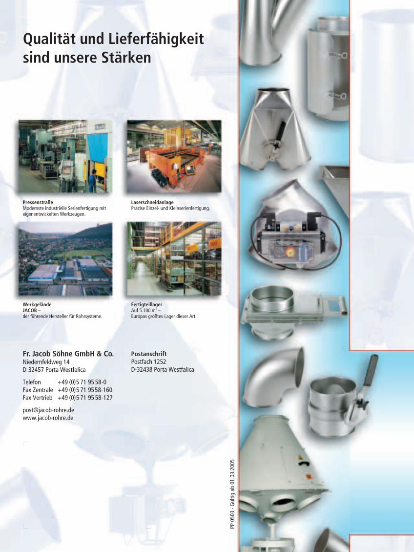
Qualität und Lieferfähigkeitsind unsere Stärken
PressenstraßeModernste industrielle Serienfertigung miteigenentwickelten Werkzeugen.
LaserschneidanlagePräzise Einzel- und Kleinserienfertigung.
FertigteillagerAuf 5.100 m2 – Europas größtes Lager dieser Art.
WerkgeländeJACOB – der führende Hersteller für Rohrsysteme.
PP 0
503
· Gül
tig a
b 01
.03.
2005
Fr. Jacob Söhne GmbH & Co.Niedernfeldweg 14D-32457 Porta Westfalica
Telefon +49 (0)5 71 95 58-0Fax Zentrale +49 (0)5 71 9558-160Fax Vertrieb +49 (0)5 71 95 58-127
PostanschriftPostfach 1252D-32438 Porta Westfalica