Embed Size (px)
Citation preview

®

2
S-presso
V1 T1686
2004 8
( 1 )
2
©2004

3
ASUSTeK COMPUTER INC.
15
886-2-2894-3447
0800-093-456
tw.asus.com
ASUS COMPUTER INTERNATIONAL
44370 Nobel Drive, Fremont ,CA 94538, USA
+1-502-933-8713
+1-502-995-0883
+1-502-933-8713
+1-502-995-0883
www.asus.com
ASUS COMPUTER GmbH
Harkort Str. 25, D-40880 Ratingen, Germany
49-2102-95990
49-2102-959911
www.asuscom.de
www.asuscom.de/sales
49-2102-95990 ... /
49-2102-959910 ...
49-2102-959911
www.asuscom.de/support

4
........................................................................................ 2
........................................................................................ 3
.......................................................................................................... 4
........................................................................................ 7
............................................................................................ 9
................................................. 1-11.1 ............................................................................................... 1-3
1.2 ............................................................................... 1-3
1.3 ................................................... 1-4
1.4 ................................................... 1-7
1.5 ................................................................................... 1-8
1.6 LED ..................................................................... 1-9
1.7 ............................................................................. 1-11
1.8 ......................................................................................... 1-12
................................................. 2-12.1 ................................................................................... 2-3
2.2 ................................................................................... 2-4
2.3 ............................................................................... 2-5
2.4 ........................................................................... 2-6
2.5 CPU ...................................................................................... 2-7
2.5.1 ......................................................................................... 2-7
2.5.2 CPU ................................................................................................ 2-8
2.3.3 ......................................................................................... 2-8
2.6 ........................................................................... 2-8
2.6.1 ............................................................................................. 2-8
2.6.2 ................................................................................... 2-10
2.6.3 ................................................................................... 2-11
2.7 ................................................................................. 2-12
2.8 ................................................................................. 2-14
2.8.1 ........................................................................................... 2-14

5
2.8.2 ........................................................................................... 2-15
2.9 ................................................................................. 2-16
2.9.1 PCI/AGP ......................................................................... 2-16
2.9.2 AGP .................................................................................. 2-17
2.9.3 ........................................................................................... 2-18
2.10 ......................................................................... 2-19
2.10.1 ................................................................................. 2-19
2.10.2 ................................................................................. 2-20
2.10.3 ......................................................................................... 2-20
2.10.4 ................................................................................. 2-21
2.11 .................................................................................... 2-22
.............................................. 3-13.1 ............................................................................... 3-3
3.2 ................................................................... 3-4
3.3 ....................................................................................... 3-5
BIOS ............................................... 4-14.1 BIOS ...................................................................... 4-2
4.1.1 .................................................................................... 4-2
4.1.2 AFUDOS BIOS ............................................................ 4-2
4.1.3 AFUDOS BIOS .................................................... 4-4
4.1.4 EZ Flash BIOS ..................................................... 4-6
4.1.5 CrashFree BIOS 2 BIOS ........................................ 4-7
4.1.6 ................................................................................ 4-9
4.2 BIOS ................................................................................... 4-10
4.3 Main Menu .............................................................. 4-13
4.4 Advanced menu ................................................... 4-17
4.4.1 CPU Configuration ................................................... 4-17
4.4.2 Chipset .......................................................................... 4-18
4.4.3 Onboard Devices Configuration .......................... 4-21
4.4.4 PCI PCIPnP .......................................................... 4-22
4.4.5 USB USB Configuration .............................................. 4-24
6
4.4.6 Load MiniLoader [Disabled] ................................................................ 4-25
4.5 Power menu ......................................................... 4-26
4.5.1 Suspend Mode [Auto] .......................................................................... 4-26
4.5.2 Repost Video on S3 Resume [No] ....................................................... 4-26
4.5.3 ACPI 2.0 Support [No] ........................................................................ 4-26
4.5.4 ACPI APIC Support [Enabled] ............................................................ 4-26
4.5.5 APM Configuration ...................................... 4-27
4.5.6 Hardware Monitor ................................................ 4-28
4.6 Boot menu ........................................................... 4-30
4.6.1 Boot Device Priority ............................................. 4-30
4.6.2 Removable drives .......................................... 4-31
4.6.3 Boot Settings Configuration .................................. 4-32
4.6.4 Security .................................................................... 4-34
4.7 BIOS Exit menu ................................................. 4-37
................................................. 5-15.1 InstantOn .................................................................................. 5-3
5.2 ................................................................................... 5-4
5.3 ........................................................................................... 5-4
5.4 ....................................................................... 5-5
5.4.1 ............................................................. 5-5
5.4.2 Drivers menu ........................................................... 5-6
5.4.3 Utilities menu .......................................................... 5-7
5.4.4 ..................................................................................... 5-8
5.5 PC Probe ............................................................ 5-9
5.5.1 ............................................................................. 5-9
5.5.2 ........................................................................... 5-10
5.5.3 ............................................................... 5-12
5.6 ................................................................................. 5-13
5.6.1 ....................................................................................... 5-13
5.6.2 ............................................................................................... 5-14
5.6.3 ........................................................................................... 5-15

7
1.
S-presso
S-presso
2.
S-presso
S-presso
3.
P4P8T
Jumper
4. BIOS
BIOS BIOS
5.
InstantOn
TVFM HomeTheater

8
1.
http://tw.asus.com
3
2.

9
•
•
•
•
•
•
•
•
• I C
•
•
•
•


S-presso
S-presso
System introduction
1.1 ............................................................................................... 1-3
1.2 ............................................................................... 1-3
1.3 ................................................... 1-4
1.4 ................................................... 1-7
1.5 ................................................................................... 1-8
1.6 LED ..................................................................... 1-9
1.7 ............................................................................. 1-11
1.8 ......................................................................................... 1-12

1-3 S-presso
1.2
1.
2.
1.1 S-presso
S-presso CPU
1. S-presso P4P8T CPU LED 2. SATA IDE 3. InstantOn HomeTheater - - 4. CD-ROM CD-RW DVD-ROM DVD-RW ASUS PVR 416 TV/FM
S1-P111 S1-P112

1-4
1.3
1.
2.
3.
4.
5. I/O
I/O
6. I/O
USB 2.0
7.
S1-P112
1
2
3
4
5
6
7

1-5 S-presso
1.
2.
3.
4.
5. I/O
I/O
6. I/O
USB 2.0
7.
S1-P111
4
5
711 14
6
17
16
15
3
8
9
131210
1
2
1-6
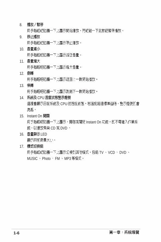
8.
9.
10.
11.
12.
13.
14. CPU
CPU
15. Instant On
Instant On
CD DVD
16. LED
17.
TV VCD DVD
MUSIC Photo FM MP3

1-7 S-presso
1.4
1. SD/MMC
SD/MMC
2. CF
CompactFlash Microdrive
3. SmartMedia
SmartMedia
4. MS
Memory Stick Memory Stick Pro
5. DVD-ROM
6.
7.
8. USB 2.0
USB USB
12
3
4
5
6 7 8

1-8
1.5
1.
2. PS/2
3. PS/2
4. VGA
5.
6.
7.
2 4 6
- /
8. USB2.0
9. 10/100Mbps LAN
10. S/PDIF
11.
12.
13.
14.
1
23
4 5 6 8 97
17
12
13 14
1011

1-9 S-presso
1.6 LED S1-P111 S1-P111 LED
1. InstantOn CD/VCD/DVD MP3
2. HomeTheater MP3/CD/VCD/DVD TV/FM
A B C D E F G
H I J K L
A. TV
B. VCD VCD
C. DVD DVD
InstantOn DVD
D. Photo Photo
E. Music Music
CD
F. MP3 MP3
MP3
G. FM FM

1-10
H. S3 Suspend-to-RAM S4
Suspend-to-Disk 24
BIOS Windows
- InstantOn
-
VCD / DVD
I.
J.
K.
L. Stereo Stereo

1-11 S-presso
1.7
1.
2.
3.
4. I/O
5. CPU
6.
2
4
5
6
7
9
81
3 10
11
12
13
7.
8. IDE
9. IDE
10.
11. AGP
12. PCI
13.

1-12
1.8 S1-P111

1-13 S-presso
power InstantOn home Home theater close Home theater pcejectlive tvguide Guidedvd/menu DVD/ASUS ASUS
backOKmore inforeplaystopskiprewpausefwdvol+vol-playch+ch-my video VCD/DVDmy musicmy tvmy picturemuteradiorec
~ 0~9repeatshuffle


S-presso
CPU
PCI AGP S-presso
Basic installation

2.1 ................................................................................... 2-3
2.2 ................................................................................... 2-4
2.3 ............................................................................... 2-5
2.4 ........................................................................... 2-6
2.5 CPU ...................................................................................... 2-7
2.5.1 ............................................................................ 2-7
2.5.2 CPU ................................................................................... 2-8
2.3.3 ............................................................................ 2-8
2.6 ........................................................................... 2-8
2.6.1 ................................................................................ 2-8
2.6.2 ...................................................................... 2-10
2.6.3 ...................................................................... 2-11
2.7 ................................................................................. 2-12
2.8 ................................................................................. 2-14
2.8.1 .............................................................................. 2-14
2.8.2 .............................................................................. 2-15
2.9 ................................................................................. 2-16
2.9.1 PCI/AGP ............................................................. 2-16
2.9.2 AGP ..................................................................... 2-17
2.9.3 .............................................................................. 2-18
2.10 ......................................................................... 2-19
2.10.1 .................................................................... 2-19
2.10.2 .................................................................... 2-20
2.10.3 ............................................................................ 2-20
2.10.4 .................................................................... 2-21
2.11 .................................................................................... 2-22

2-3 S-presso
S B _ P W R( 1 ) ( 2 ) ( 3 )
P4P8T ®
P4P8T Onboard LED
SB_PWR
ONStandbyPower
OFFPowered
Off
1.
2.
3.
4.
2.1
1. CPU
2.
3. PCI / AGP
4.
5.
6.
2-4
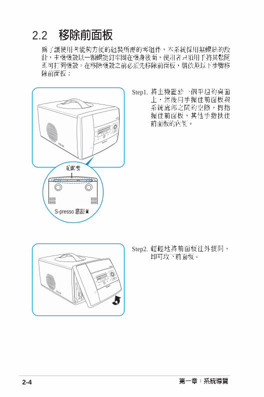
2.2
Step1.
Step2.
S-presso
2-5 S-presso
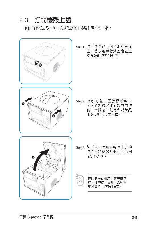
2.3
Step1.
Step2.
Step3.

2-6
2.4 CPU
Step1. 1
2
Step2.
Step3.

2-7 S-presso
2.5 CPU CPU
CPU
2.5.1
Step1. CPU
CPU
Step2. CPU_FAN CPU CPU
CPU CPU

2-8
2.5.2 CPU
CPU Pentium
2.3.3
Step1. CPU 90-100
Step2. Pentium 4
CPU
Step3.
Step1. C P U
CPU_FAN
Step2.

2-9 S-presso
2.6 184-pin DDR DIMM Double Data Rate
unbuffered non-ECC PC3200/2700/2100 DDR DIMM 2 GB
DDR DIMM
2.6.1 64, 128, 256, 512MB 1GB DDR DIMM
CPU
CPU FSB DDR DDR
800MHz PC3200/PC2700/PC2100 400/333*/266MHz
533MHz PC2700/PC2100 333/266MHz
400MHz PC2100 266MHz
800MHz FSB CPU PC2700 DDR 320MHz 333MHz
1. 2-8 DDR400
2.
3. CL CAS-Latency
4. x4,x8,x16
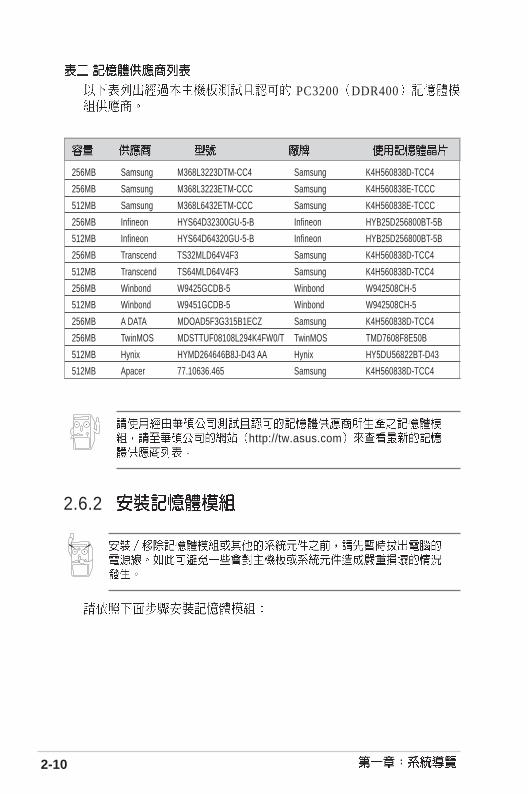
2-10
http://tw.asus.com
2.6.2
256MB Samsung M368L3223DTM-CC4 Samsung K4H560838D-TCC4
256MB Samsung M368L3223ETM-CCC Samsung K4H560838E-TCCC
512MB Samsung M368L6432ETM-CCC Samsung K4H560838E-TCCC
256MB Infineon HYS64D32300GU-5-B Infineon HYB25D256800BT-5B
512MB Infineon HYS64D64320GU-5-B Infineon HYB25D256800BT-5B
256MB Transcend TS32MLD64V4F3 Samsung K4H560838D-TCC4
512MB Transcend TS64MLD64V4F3 Samsung K4H560838D-TCC4
256MB Winbond W9425GCDB-5 Winbond W942508CH-5
512MB Winbond W9451GCDB-5 Winbond W942508CH-5
256MB A DATA MDOAD5F3G315B1ECZ Samsung K4H560838D-TCC4
256MB TwinMOS MDSTTUF08108L294K4FW0/T TwinMOS TMD7608F8E50B
512MB Hynix HYMD264646B8J-D43 AA Hynix HY5DU56822BT-D43
512MB Apacer 77.10636.465 Samsung K4H560838D-TCC4
PC3200 DDR400

2-11 S-presso
DDR DIMM
1. DDR DIMM
2. DDR
3. DDR
4.
2.6.3
1.
2.

2-12
Step1.
2.7
S-presso
CD-ROMCD-RW DVD-ROM DVD-RW
52xmax
52xmax
2
Step2. 5 . 2 5
Master
2-13 S-presso
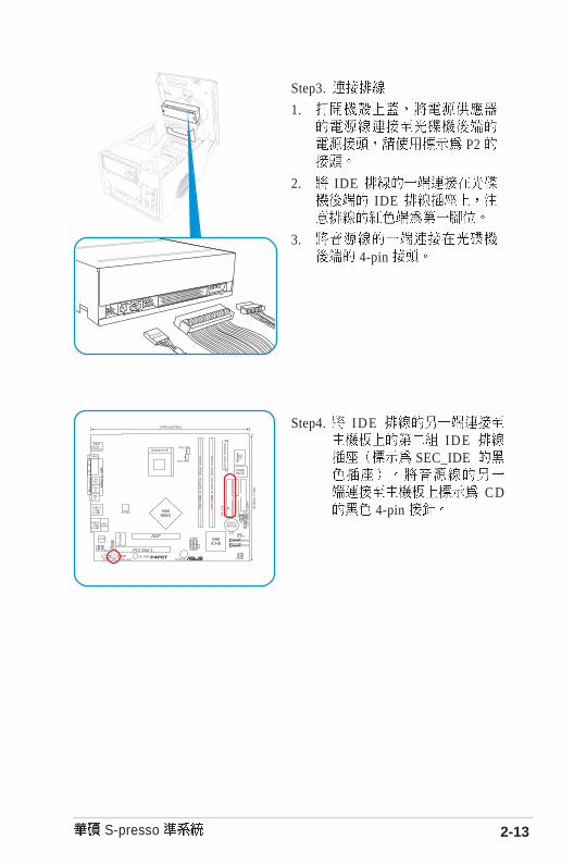
Step3.
1.
P2
2. IDE IDE
3. 4-pin
Step4. IDE IDE
SEC_IDE
CD 4-pin
CHA_FAN
FLO
PP
Y
CD1
AD1888
AUX1
USB56
P4P8T ®
PCI Slot 1
Super
I/O
FlashBIOS
PS/2T:MouseB:Keyboard
SE
C_I
DE
ATX12V
PAR
AL
LE
L P
OR
T
VGA1
MicIn
LineIn
LineOut
BUZZER
Socket 478
CLRTC
PR
I_ID
E
CPU_FAN
24.89cm (9.8in)
20.0
6cm
(7.
9in)
DD
R D
IMM
_A1
(64/
72-b
it, 1
84-p
in m
odul
e)
DD
R D
IMM
_B1
(64/
72-b
it, 1
84-p
in m
odul
e)
AGP
USB2.0T: USB3B: USB4
Top:RJ-45
SB_PWRPANEL
FP_AUDIO
SPDIF OUT
MDC
IntelICH5
Intel865G
CR2032 3VLithium Cell
CMOS Power
USB78
ATX
Pow
er C
onne
ctor
SATA2
SATA1
USB2.0T: USB1B: USB2
J1
LCD
_PA
NE
L
RT
L810
0C

2-14
2.8
3.5 5.25
Step1.
Step2.
Step3.
2.8.1
2 2
1

2-15 S-presso
Step4. IDE IDE
2.8.2
3
1
2
3
IDE
Step5. IDE IDE
PRI_IDE CHA_FAN
FLO
PP
Y
CD1
AD1888
AUX1
USB56
P4P8T ®
PCI Slot 1
Super
I/O
FlashBIOS
PS/2T:MouseB:Keyboard
SE
C_I
DE
ATX12V
PAR
AL
LE
L P
OR
T
VGA1
MicIn
LineIn
LineOut
BUZZER
Socket 478
CLRTC
PR
I_ID
E
CPU_FAN
24.89cm (9.8in)
20.0
6cm
(7.
9in)
DD
R D
IMM
_A1
(64/
72-b
it, 1
84-p
in m
odul
e)
DD
R D
IMM
_B1
(64/
72-b
it, 1
84-p
in m
odul
e)
AGP
USB2.0T: USB3B: USB4
Top:RJ-45
SB_PWRPANEL
FP_AUDIO
SPDIF OUT
MDC
IntelICH5
Intel865G
CR2032 3VLithium Cell
CMOS Power
USB78
ATX
Pow
er C
onne
ctor
SATA2
SATA1
USB2.0T: USB1B: USB2
J1
LCD
_PA
NE
L
RT
L810
0C
Step2. 1
Step1.
2-16
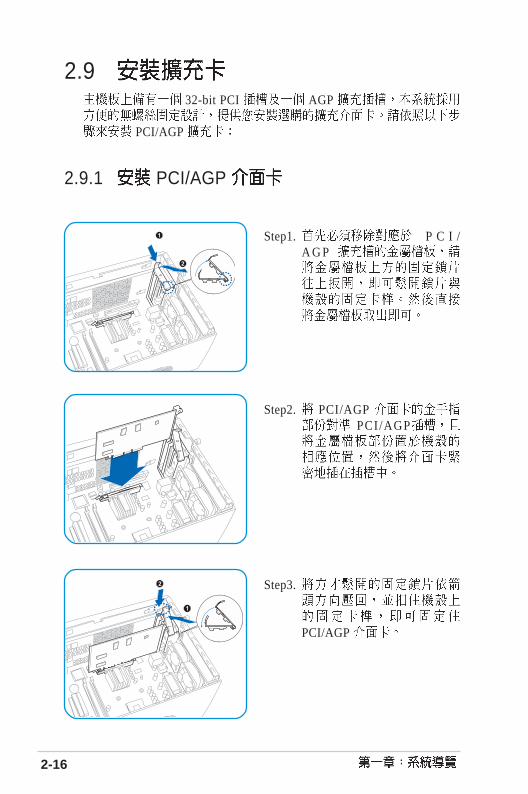
2.9 32-bit PCI AGP
PCI/AGP
2.9.1 PCI/AGP
Step2. PCI/AGP PCI/AGP
Step1. P C I /A G P
Step3.
PCI/AGP

2-17 S-presso
ATi 9500 9700 Pro PN xxx-xxxxx-30
2.9.2 AGP AGP8X AGP4X Accelerated Graphics Port
AGP AGP +1.5V AGP
PCI AGP
+1.5V AGP 3.3V AGP
P4P8T ®
P4P8T Accelerated Graphics Port (AGP)
Keyed for 1.5v

2-18
2.9.3
1. BIOS BIOS
2. IRQ
3.
IRQ0 11 27* 15 LPT 18 3 CMOS/9* 4 ACPI 10* 5 PCI 11* 6 PCI 12* 7 PS/2 13 814* 9 IDE 15* 10 IDE
*
A B C D E F G HPCI - - - - - - -AGP - - - - - -
USB HC0 - - - - - - -USB HC1 - - - - - - -USB HC2 - - - - - - -USB HC3 - - - - - - -USB 2.0 - - - - - - -
- - - - - - -- - - - - - -

2-19 S-presso
2.10
2.10.1
Step2. 1
Step1.

2-20
2.10.2
P1. ATX
P2.
P3.
P4.
P5. ATX 12V
2.10.3
1. 100-127V 115V
2. 200-240V 230V
230V 115V

2-21 S-presso
2.10.4
+3.3V +/-5% +3.14 +3.3 +3.47
+5V +/-5% +4.75 +5 +5.25
+12V +/-5% +11.4 +12 +12.6
-12V +/-10% -10.8 -12 -13.2
+5VSB +/-5% +4.75 +5 +5.25
Min Nom Max
1 90V 115V 132V
2 180V 230V 264V
47 Hz to 63 Hz
AC 5A max at 115Vac3A max. at 230Vac, full load
45 A @115Vrms90A @230Vrms(at 25 ambient cold start)
70*70*10 mm
34

2-22
2.11
Step2.
Step1.
Step3.

P4P8T
Jumper
Motherboard Info.

3.1 ............................................................................... 3-3
3.2 ................................................................... 3-4
3.3 ....................................................................................... 3-5

3-3 S
-presso
CH
A_FA
N
FLOPPY
CD
1
AD
1888
AU
X1
US
B56
P4
P8
T®
PC
I Slot 1
Super I/O
Fla
shB
IOS
PS
/2T:M
ouseB
:Keyboard
SEC_IDEA
TX
12V
PARALLEL PORT
VG
A1
Mic
In
LineIn
LineO
ut
BU
ZZ
ER
So
cket 4
78
CLR
TC
PRI_IDE
CP
U_FA
N
24.89cm (9.8in)
20.06cm (7.9in)
DDR DIMM_A1 (64/72-bit, 184-pin module)
DDR DIMM_B1 (64/72-bit, 184-pin module)
AG
P
US
B2.0
T: USB3B: USB4
Top:R
J-45
SB
_PW
RP
AN
EL
FP
_AU
DIO
SP
DIF
OU
T
MD
C
IntelIC
H5
Intel865G
CR
2032 3VLithium
Cell
CM
OS
Pow
er
US
B78
ATX Power Connector
SA
TA2
SA
TA1
US
B2.0
T: USB1B: USB2
J1
LCD_PANEL
RTL8100C
3.1
CPU
IDE IDE
3-4
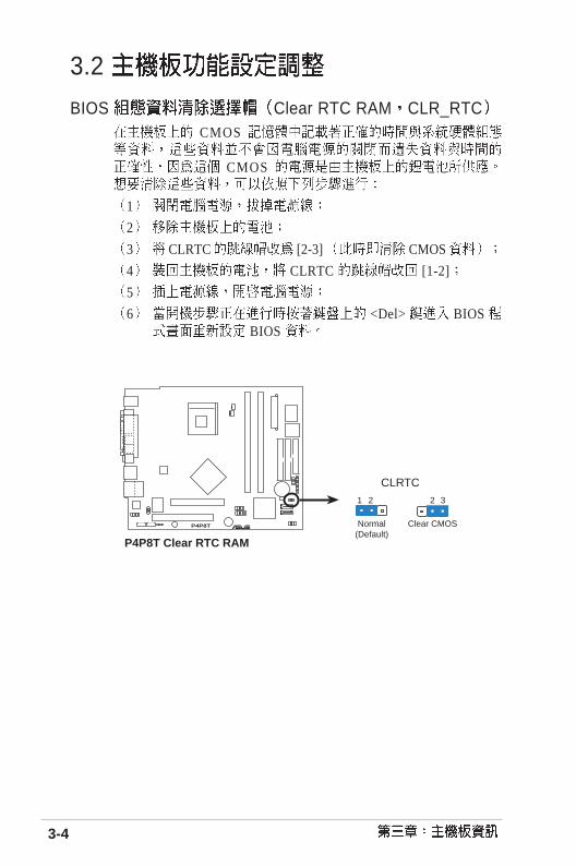
3.2
BIOS Clear RTC RAM CLR_RTC CMOS
CMOS
1
2
3 CLRTC [2-3] CMOS
4 CLRTC [1-2]
5
6 <Del> BIOS BIOS
P4P8T ®
P4P8T Clear RTC RAM
CLRTC
Normal Clear CMOS(Default)
1 2 2 3

3-5 S-presso
3.3
1. (20-pin ATXPWR, 4-pin ATX +12V) ATX +12V
20 ATXPWR Pentium® 4 +12V
P4P8T ®
P4P8T ATX power connector
+3.3Volts-12.0VoltsGroundPower Supply OnGroundGroundGround-5.0 Volts+5.0 Volts+5.0 Volts
Power Good
+12.0Volts
+3.3 Volts+3.3 Volts
Ground+5.0 Volts
Ground+5.0 Volts
Ground
+5V Standby
ATX12V
ATXPWR
+12V DC
Ground+12V DC
Ground

3-6
2. LED SB_PWR1
(1) (2) (3)
P4P8T ®
P4P8T Onboard LED
SB_PWR
ONStandbyPower
OFFPowered
Off

3-7 S-presso
4. IDE 40-1 pin IDE1, IDE2 IDE IDE
IDE CD-ROM ZIP MO IDE
M a s t e rS lave
P r i m a r ySecondary Slave UltraDMA100/66 IDE
Master UltraDMA100/66 IDE
Slave U l t r a D M A 1 0 0 / 6 6
UltraDMA100/66
UltraDMA100/66 IDE 80 IDE
80 IDE UltraDMA100/66
1. IDE UltraDMA
2. UltraDMA100/66
P4P8T ®
P4P8T IDE connectors
NOTE: Orient the red markings(usually zigzag) on the IDEribbon cable to PIN 1.
SE
C_I
DE
PIN 1
PR
I_ID
E

3-8
5. 3-pin CPU_FAN1, CHA_FAN1
350mA 4.2 12
Rotation RPM Rota t ions Pe r
Minute
P4P8T ®
P4P8T Fan connectors
CPU_FANGND
Rotation+12V
CHA_FANGND
Rotation+12V
CPU C P U j u m p e r s
jumper

3-9 S-presso
6. Serial ATA 7-pin SATA2, SATA1
Serial ATA Serial ATA 150MB 133MB
Parallel ATA Ultra ATA/133
Serial ATA 1. Serial ATA
Serial ATA Parallel ATA
2. Serial ATA 3. Serial ATA Windows XP Service
Pack 1
P4P8T ®
P4P8T SATA connectors
SATA2
GN
DR
SAT
A_T
XP
2R
SAT
A_T
XN
2G
ND
RS
ATA
_RX
P2
RS
ATA
_RX
N2
GN
D
SATA1
GN
DR
SAT
A_T
XP
1R
SAT
A_T
XN
1G
ND
RS
ATA
_RX
P1
RS
ATA
_RX
N1
GN
D
ATA ATA
Intel ICH5 ATA ATA
Windows 2000/XP
IDE
Windows 2000/XP ICH5 6 IDE
MS-DOS Windows 98SE/Me/NT4.0 ICH5 4 IDE

3-10
-ATA -ATA 0 1
(2 ) (2 ) (1 ) (1 )
1. Windows 2000/XP
2. Windows 98/Me/NT4.0
A -
B -
C - -
IDE BIOS
BIOS ATA ATA BIOS 2.3.
6 IDE
Windows 2000/XP Windows 98/Me/NT4.0 BIOS A B C
Onboard IDE Operate Mode Enhanced Mode Compatible Mode Compatible Mode Compatible Mode
Enhanced Mode Support On S-ATA - - -
IDE Port Settings - Pri. P-ATA+S-ATA Sec.P-ATA & S-ATA P-ATA Only
Windows 2000/XP BIOS EnhancedMode S-ATA 2 ATA 4
ATA
-

3-11 S-presso
7. (4-pin AUX1, CD1,)CD1 CD-ROM AUX1 TV/FM
P4P8T ®
P4P8T Internal audio connectors
AUX1 (White) CD1 (Black)
Rig
ht A
udio
Cha
nnel
Left
Aud
io C
hann
elG
roun
d
Rig
ht A
udio
Cha
nnel
Left
Aud
io C
hann
elG
roun
d8. LCD Panel (26-1pin LCD_PANEL)
LED
P4P8T ®
P4P8T LCD_PANEL connector
LCD_PANEL
PIC_CLK
+5VSB GNDPIC_STB# PIC_DOUTPIC_CLK PIC_DIN
PIC_DINPIC_STB# PIC_DOUTDJ_PLAY +5V
DJ_SCANFW DJ_SCANRWSMBDATA +5VSB
SMBCLK GND+12V
DJ_VOLUP DJ_VOLDNDJ_STOP#
3-12
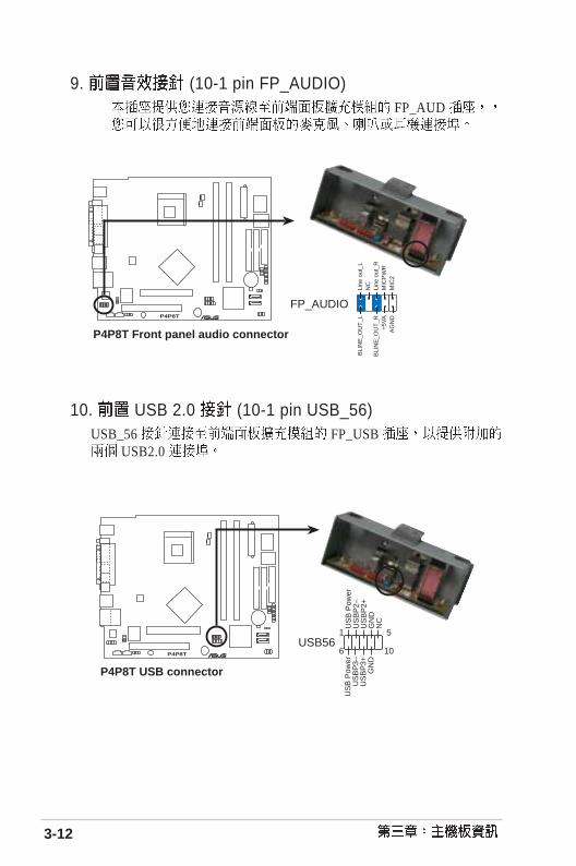
10. USB 2.0 (10-1 pin USB_56)USB_56 FP_USB
USB2.0
P4P8T ®
P4P8T USB connector
USB56
US
B P
ower
US
BP
2–U
SB
P2+
GN
DN
C
US
B P
ower
US
BP
3–U
SB
P3+
GN
D
1 5
6 10
9. (10-1 pin FP_AUDIO) FP_AUD
P4P8T ®
P4P8T Front panel audio connector
FP_AUDIO
BLI
NE
_OU
T_L
MIC
2
Line
out
_R
Line
out
_L
BLI
NE
_OU
T_R
NC
MIC
PW
R+
5VA
AG
ND

3-13 S-presso
P4P8T ®
P4P8T Digital audio connector
+5V
SP
DIF
OU
TG
ND
SPDIF OUT
11. 4-1 pin SPDIF_OUT1 S/PDIF S/
PDIF
P4P8T ®
P4P8T USB connector
US
B P
ower
US
BP
2–U
SB
P2+
GN
D+
5VP
ower
Bot
ton
US
B P
ower
US
BP
3–U
SB
P3+
GN
D
Dum
my
1
USB78
12. USB 2.0 (12-1 pin USB78)USB78 6-1 pin CON5 6pin CIR 00
3-14
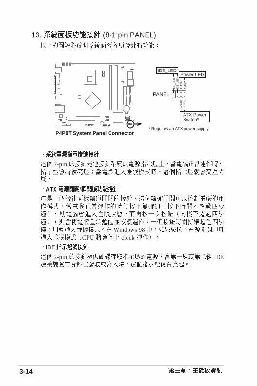
2-pin
ATX /
Windows 98 CPU clock
IDE
2-pin IDE
13. (8-1 pin PANEL)
P4P8T ®
P4P8T System Panel Connector* Requires an ATX power supply.
PLE
D+
Gro
und
Power LED
PW
R
ATX PowerSwitch*
PLE
D-
IDE
_LE
D+
IDE
_LE
D-
IDE_LED
PANEL

BIOS BIOS BIOS
BIOS <Del>
BIOS
BIOS information

4.1 BIOS ...................................................................... 4-2
4.1.1 ....................................................................... 4-2
4.1.2 AFUDOS BIOS ............................................... 4-2
4.1.3 AFUDOS BIOS ....................................... 4-4
4.1.4 EZ Flash BIOS ........................................ 4-6
4.1.5 CrashFree BIOS 2 BIOS ........................... 4-7
4.1.6 ................................................................... 4-9
4.2 BIOS ................................................................................... 4-10
4.3 Main Menu .................................................................. 4-13
4.4 Advanced menu ................................................... 4-17
4.4.1 CPU Configuration ...................................... 4-17
4.4.2 Chipset ............................................................. 4-18
4.4.3 Onboard Devices Configuration .............. 4-21
4.4.4 PCI PCIPnP ............................................. 4-22
4.4.5 USB USB Configuration ................................. 4-24
4.4.6 Load MiniLoader [Disabled] ................................................... 4-25
4.5 Power menu ......................................................... 4-26
4.5.1 Suspend Mode [Auto] ............................................................. 4-26
4.5.2 Repost Video on S3 Resume [No] .......................................... 4-26
4.5.3 ACPI 2.0 Support [No] ............................................................ 4-26
4.5.4 ACPI APIC Support [Enabled] ............................................... 4-26
4.5.5 APM Configuration ......................... 4-27
4.5.6 Hardware Monitor ................................... 4-28
4.6 Boot menu ........................................................... 4-30
4.6.1 Boot Device Priority ................................. 4-30
4.6.2 Removable drives ............................. 4-31
4.6.3 Boot Settings Configuration ..................... 4-32
4.6.4 Security ........................................................ 4-34
4.7 BIOS Exit menu ................................................. 4-37

4-3 S-presso
4.1 BIOS
BIOS BIOS
USB
BIOS BIOS
4.1.11.
DOS a. 1.44 MB DOS
format A:/S <Enter>
b.
Windows 98SE a. MS-DOS
b. MS-DOS 1.44 MB DOS format A:/S <Enter>
c.
Windows XP a. 1.44 MB
b.
c. 3.5
d.
e. MS-DOS
2. BIOS
4.1.2 AFUDOS BIOS DOS AFUDOS.EXE BIOS
1. tw.www.asus.com BIOS

4-4 BIOS
BIOS
A:\>afudos /ip4p8t.rom
AMI Firmware Update Utility - Version 1.10
Copyright (C) 2002 American Megatrends, Inc. All rights reserved.
Reading file ..... done
Erasing flash .... done
Writing flash .... 0x0008CC00 (9%)
BIOS
DOS
A:\>afudos /ip4p8t.rom
AMI Firmware Update Utility - Version 1.10
Copyright (C) 2002 American Megatrends, Inc. All rights reserved.
Reading file ..... done
Erasing flash .... done
Writing flash .... 0x0008CC00 (9%)
Verifying flash .. done
A:\>
5.
2 . AFUDOS.EXE BIOS
3.
4. DOS
afudos/i<filename>
filenameBIOS

4-5 S-presso
4.1.3 AFUDOS BIOS AFUDOS.EXE BIOS
BIOS
1. DOS
afudos/0<filename>
filename
BIOS
A:\>afudos /oMYBIOS03.rom
AMI Firmware Update Utility - Version 1.10
Copyright (C) 2002 American Megatrends, Inc. All rights reserved.
Reading flash ..... done
A:\>
2. BIOS 600KB
BIOS DOS
A:\>afudos /oMYBIOS03.rom
AMI Firmware Update Utility - Version 1.10
Copyright (C) 2002 American Megatrends, Inc. All rights reserved.
Reading flash ..... 0x0008CC00 (9%)

4-6 BIOS
4.1.4 EZ Flash BIOS EZ Flash BIOS
DOS EZ Flash BIOSP o w e r - O n S e l f
Test POST <Alt> + <F2> EZ Flash
EZ Flash BIOS 1. www.asus.com.tw BIOS
P4P8T.ROM
2.
3. POST <Alt> + <F2> EZ Flash
4. BIOS EZ Flash BIOS
BIOS
User recovery requested. Starting BIOS recovery...
Checking for floppy...
Floppy not found BIOS
P4PT.ROM not found BIOS P4P8T.ROM
User recovery requested. Starting BIOS recovery...
Checking for floppy...
Floppy found!
Reading file “p4p8t.rom”. Completed.
Start flashing...
Flashed successfully. Rebooting.

4-7 S-presso
4.1.5 CrashFree BIOS 2 BIOS CrashFree BIOS 2 BIOS
BIOS BIOS
1. BIOS BIOS
2. BIOS BIOS
BIOS 1.
2. BIOS
BIOS
4.
3. BIOS B I O S
Bad BIOS checksum. Starting BIOS recovery...
Checking for floppy...
Floppy found!
Reading file “p4p8t.rom”. Completed.
Start flashing...
Bad BIOS checksum. Starting BIOS recovery...
Checking for floppy...
BIOS P4P8T.ROM

4-8 BIOS
BIOS 1.
2. BIOS
Bad BIOS checksum. Starting BIOS recovery...
Checking for floppy...
Bad BIOS checksum. Starting BIOS recovery...
Checking for floppy...
Floppy not found!
Checking for CD-ROM...
CD-ROM found.
Reading file “p4p8t.rom”. Completed.
Start flashing...
3. BIOS
BIOS
4. BIOS
BIOS BIOS http://www.asus.com.tw BIOS

4-9 S-presso
4.1.6 BIOS
2. Next
1.AsusUpdate Vx.xx.xx
ASUSUpdate Vx.xx.x
3.
FTP
Auto Select Next
4. BIOS Next
5.BIOS
BIOS
BIOS

4-10 BIOS
4.2 BIOS BIOS Basic Input and Output System
BIOS
BIOS BIOS
RUN SETUP BIOS
BIOS
EEPROM Electrical Erasable ProgrammableRead-Only Memory BIOS EEPROM
BIOS BIOS BIOS
CMOS RAM
BIOS
POST Power-On Self Test DELETE
DELETE
RESET CTRL + ALT + DEL
BIOS
BIOS BIOS

4-11 S-presso
4.2.1 BIOS
BIOS
Main
Advanced
Power
Boot
Exit BIOS
System Time [11:10:19]System Date [Thu, 09/27/2003]Legacy Diskette A [1.44M, 3.5 in.]
Primary IDE Master [ST321122A] Primary IDE Slave [ASUS CDS520/] Secondary IDE Master [Not Detected] Secondary IDE Slave [Not Detected] Third IDE Master [Not Detected] Fourth IDE Master [Not Detected] IDE Configuration
System Information
Use [ENTER], [TAB] or[SHIFT-TAB] to select afield.
Use [+] or [-] toconfigure system time.

4-12 BI0OS
<Enter>
<Enter>
<PageUp> <PageDown>

4-13 S-presso
BIOS
4.3.1 System Time [XX:XX:XX]
00 23 00 59 00 59 Tab Tab + Shift
4.3.2 System Date [XX/XX/XXXX]
1 12 1 31 00 99 Tab Tab + Shift
4.3.3 Legacy Diskette A [1.44M, 3.5 in.][360K 5.25 in.] [1.
2M 5.25 in.] [720K 3.5 in.] [1.44M 3.5 in,] [2.88M 3.5 in.][None]
4.3 Main Menu
System Time [11:10:19]System Date [Thu, 09/27/2003]Legacy Diskette A [1.44M, 3.5 in.]
Primary IDE Master [ST321122A]Primary IDE Slave [ASUS CDS520/]Secondary IDE Master [Not Detected]Secondary IDE Slave [Not Detected]Third IDE Master [Not Detected]Fourth IDE Master [Not Detected]IDE Configuration
System Information
Use [ENTER], [TAB] or[SHIFT-TAB] to select afield.
Use [+] or [-] toconfigure system time.

4-14 BI0OS
4.3.4 IDE Primary/Secondary/Third/ Fourth IDE Master/Slave
BIOS IDE ATA IDE ATA
[Enter]
Primary IDE Master
Device : Hard DiskVendor : ST320413ASize : 20.0GBLBA Mode : SupportedBlock Mode : 16 SectorsPIO Mode : SupportedAsync DMA : MultiWord DMA-2Ultra DMA : Ultra DMA-5SMART Monitoring: Supported
Type [Auto]LBA/Large Mode [Auto]Block (Multi-sector Transfer) [Auto]PIO Mode [Auto]DMA Mode [Auto]Smart Monitoring [Auto]32Bit Data Transfer [Auto]
Select the type ofdevice connected to thesystem.
BIOS N/A
Type [Auto]
IDE Auto IDE CDROM IDE
ARMD (ATAPI ) IDE ZIP LS-120 MO
[Not Installed] [Auto] [CDROM] [ARMD]
LBA/Large Mode [Auto]
LBA [Auto] LBA LBA
[Disabled] [Auto]
Block (Multi-sector Transfer) [Auto]
[Auto] [Disabled]
[Disabled][Auto]
4-15 S-presso
PIO Mode [Auto]
PIO [Auto] [0] [1] [2] [3] [4]
DMA Mode [Auto]
DMA [Auto] [SWDMA0] [SWDMA1] [SWDMA2][MWDMA0] [MWDMA1] [MWDMA2] [UDMA0] [UDMA1] [UDMA2][UDMA3] [UDMA4] [UDMA5]
SMART Monitoring [Auto]
Smart Monitoring, Analysis, and ReportingTechnology [Auto] [Disabled] [Enabled]
32Bit Data Transfer [Disabled]
32 [Disabled] [Enabled]
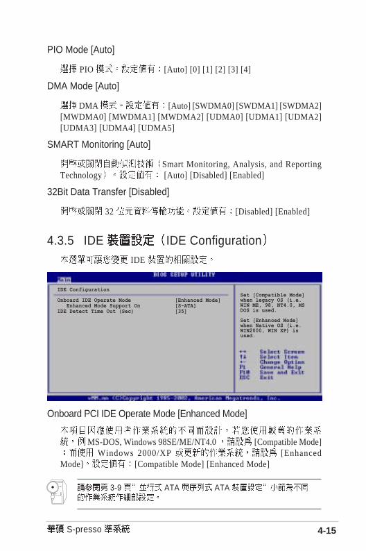
Onboard PCI IDE Operate Mode [Enhanced Mode]
MS-DOS, Windows 98SE/ME/NT4.0 [Compatible Mode] Windows 2000/XP [Enhanced
Mode] [Compatible Mode] [Enhanced Mode]
3-9 ATA ATA
4.3.5 IDE IDE Configuration IDE
IDE Configuration
Onboard IDE Operate Mode [Enhanced Mode] Enhanced Mode Support On [S-ATA]IDE Detect Time Out (Sec) [35]
Set [Compatible Mode]when legacy OS (i.e.WIN ME, 98, NT4.0, MSDOS is used.
Set [Enhanced Mode]when Native OS (i.e.WIN2000, WIN XP) isused.

4-16 BI0OS
Enhanced Mode Support On [S-ATA] [ S - A T A ]
ATA ATA
MS-DOS Windows 98SE/ME/NT4.0 ATA [P-ATA+S-ATA] [P-ATA]
[P-ATA+S-ATA] [S-ATA] [P-ATA]
IDE Detect Time Out (Sec) [35] ATA/ATAPI [0] [5] [10]
[15] [20] [25] [30] [35]
4.3.6 System Information BIOS
AMI BIOS BIOS
Processor
System Memory
AMI BIOSVersion : 08.00.09Build Date : 06/04/04ID : A010302
ProcessorType : Intel(R) Pentium(R) 4 CPU 2.80GSpeed : 2800MHzCount : 1
System MemorySize : 512MB

4-17 S-presso
4.4 Advanced menu
CPU ConfigurationChipsetOnboard Devices ConfigurationPCIPnPUSB Configuration
Load MiniLoader [Disabled]
Configure CPU.
4.4.1 CPU Configuration
Configure advanced CPU settings
Manufacturer : Intel(R)Brand String : Intel(R) Pentium(R) 4 CPU 2.80GFrequency : 2800MHzFSB Speed : 800MHz
Cache L1 : 8 KBCache L2 : 512 KBCache L3 : 0 KB
Ratio Status : lockedRatio Actual Value : 14Max CPUID Value Limit [Disabled]
Hyper-Threading Technology [Enabled]
Sets the ration betweenCPU Core Clock and theFSB Freuency.
Note: If an invalidratio is set in CMOS,then actual and setpointvalues may differ.

4-18 BI0OS
L3 Cache [Enabled] L3 [Enabled] [Disabled]
Max CPUID Value Limit [Disabled] C P U I D
[Disabled] [Enabled]
Hyper-Threading Technology [Enabled]H y p e r -
Threading Technology [Enabled] [Disabled]
H y p e r - T h r e a d i n gTechnology Intel Pentium 4
4.4.2 Chipset
Advanced Chipset settings
WARNING: Setting wrong values in the sections below may cause system to malfunction.
DDR Reference Voltage [Auto]DRAM Frequency [Auto]Configure DRAM Timing by SPD [Enabled]Internal Graphic Acceleration Mode [Auto]
Graphic Adapter Priority [AGP/Int-VGA]Onboard Video Memory [Enabled, 8MB]Graphics Aperture Size [ 64MB]
Boot Display Device [Auto]Flat Panel type [640x480LVDS]TV Standard [Auto]
MPS Revision [1.4]
Set DDR referencevoltage.
DDR Reference Voltage [Auto] DDR SDRAM [Auto] [2.55V] [2.
65V]
DRAM Frequency [Auto][266MHz] [333MHz]
[400MHz] [Auto]

4-19 S-presso
Configure DRAM Timing by SPD [Enabled]
SPD Serial Presence Detect[Disabled] [Enabled]
Configure DRAM Timing by SPD [Disabled]
DRAM CAS# Latency [2.5 Clocks]
SDRAM [ 2 . 0
Clocks][2.5 Clocks][3.0 Clocks]
DRAM RAS# Precharge [4 Clocks]
SDRAM Precharge [ 4
Clocks][3 Clocks][2 Clocks]
DRAM RAS# to CAS# Delay [4 Clocks]
SDRAM /
[4 Clocks][3 Clocks][2 Clocks]
DRAM Precharge Delay [8 Clocks]
SDRAM SDRAM [8 Clocks][7 Clocks][6 Clocks][5 Clocks]
DRAM Burst Length [8 Clocks]
[8 Clocks][4 Clocks]
Internal Graphic Accelerate Mode [Auto]
[ 2 T ] [ 1 T ][Auto]
Graphic Adapter Priority [AGP/Int-VGA]
[ I n t e r n a l V G A ] [ A G P / I n t - V G A ] [ A G P / P C I ] [ P C I / A G P ][PCI/Int-VGA]

4-20 BI0OS
Onboard Video Memory [Enabled, 8MB]
[Disabled] [Enabled, 1MB] [Enabled, 4MB][Enabled, 8MB] [Enabled, 16MB] [Enabled, 32MB]
Graphics Aperture Size [64MB]
AGP [4MB] [8MB] [16MB] [32MB] [64MB] [128MB] [256MB]
Boot Display Device [Auto]
[Auto] [CRT][TV] [EFP] [LFP] [CRT+EFP] [CRT+LFP]
Flat Panel Type [640x480 LVDS]
[640x480LVDS] [640x480CMOS][800x600LVDS] [800x600CMOS][1024x768LVDS] [1024x768CMOS][1280x1024LVDS] [1280x1024CMOS][1400x1050LVDS] [1400x1050CMOS][1600x1200LVDS] [1600x1200CMOS]
TV Standard [Auto]
[Auto] [NTSC_M] [PAL_B] [SECAM_L][NTSC_M_J] [PAL_G] [SECAM_L]1[NTSC_433] [PAL_D] [SECAM_B][NTSC_N] [PAL_H]
[PAL_I][PAL_M][PAL_N][PAL_60]
MPS Revision [1.4]
[1.1] [1.4]

4-21 S-presso
4.4.3 Onboard DevicesConfiguration
Onboard AC 97 Audio [Auto]
AC97 [Disabled] [Auto]
OnBoard LAN [Enabled]
[Disabled] [Enabled]
OnBoard LAN Boot ROM [Disabled]
OnBoard LAN [Enabled]B o o t R O M
[Disabled] [Enabled]
Parallel Port Address [378]
[Disabled] Parallel Port Mode Parallel Port IRQ
[Disabled] [378] [278] [3BC]
Onboard AC’97 Audio� [Auto]Onboard LAN [Enabled] OnBoard LAN Boot ROM [Disabled]
Parallel Port Address [378]Parallel Port Mode [EPP+ECP] EPP Version [1.9] ECP Mode DMA Channel [DMA3] Parallel Port IRQ [IRQ7]
4-22 BI0OS
EPP Version [1.9]
E P P Parallel Port Mode [EPP] [1.9] [1.7]
ECP Mode DMA Channel [DMA3]
E C P D M A Parallel Port Mode [ECP] [DMA0] [DMA1][DMA3]
Parallel Port IRQ [IRQ7]
I R Q [ I R Q 5 ][IRQ7]
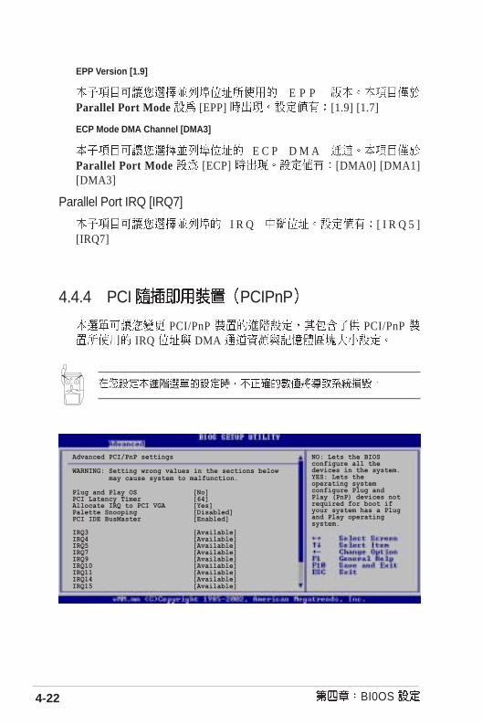
4.4.4 PCI PCIPnP
PCI/PnP PCI/PnP IRQ DMA
NO: Lets the BIOSconfigure all thedevices in the system.YES: Lets theoperating systemconfigure Plug andPlay (PnP) devices notrequired for boot ifyour system has a Plugand Play operatingsystem.
Advanced PCI/PnP settings
WARNING: Setting wrong values in the sections below may cause system to malfunction.
Plug and Play OS [No]PCI Latency Timer [64]Allocate IRQ to PCI VGA [Yes]Palette Snooping [Disabled]PCI IDE BusMaster [Enabled]
IRQ3 [Available]IRQ4 [Available]IRQ5 [Available]IRQ7 [Available]IRQ9 [Available]IRQ10 [Available]IRQ11 [Available]IRQ14 [Available]IRQ15 [Available]

4-23 S-presso
Plug and Play O/S [No]
[No], BIOS [Yes] [No] [Yes]
PCI Latency Timer [64]
PCI [32] [64][96] [128] [160] [192] [224] [248]
Allocate IRQ to PCI VGA [Yes]
PCI IRQ [No] [Yes]
Pallete Snoopping [Disabled]
MPEG [Enabled]
V G A [Disabled] [Disabled] [Enabled]
PCI IDE BusMaster [Enabled]
BIOS PCI IDE [Disabled] [Enabled]
IRQ xx [Available]
IRQ PCI/PnP [Available] ISA [Reserved] [Available]
[Reserved]

4-24 BI0OS
4.4.5 USB USB Configuration USB
USB Devices Enabled None
USB Function [8 USB Ports]
USB [Disabled] [2USB Ports] [4 USB Ports] [6 USB Ports] [8 USB Ports]
Legacy USB Support [Auto]
USB [Auto] USB
USB [Disabled] USB USB
[Disabled] [Enabled] [Auto]
USB 2.0 Controller [Enabled]
U S B 2 . 0 [ E n a b l e d ][Diabled]
USB 2.0 Controller Mode [FullSpeed]
U S B 2 . 0 HiSpeed (480 Mbps) Full Speed (12 Mbps) [FullSpeed] [HiSpeed]
USB Configuration
Module Version : 2.22.4-5.3
USB Devices Enabled : None
USB Function [8 USB Ports]Legacy USB Support [Auto]USB 2.0 Controller [Enabled]USB 2.0 Controller Mode [FullSpeed]
USB Mass Storage Device Configuration
Enables USB hostcontrollers.
4-25 S-presso
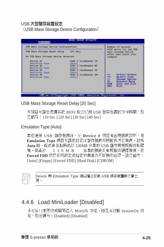
USB USB Mass Storage Device Configuration
USB Mass Storage Device Configuration
USB Mass Storage Reset Delay [20 Sec]
No USB Mass Storage device detected
Device #1 USB2.0 CardReader CF Emulation Type [Auto] Device #2 USB2.0 CardReader MS Emulation Type [Auto] Device #3 USB2.0 CardReader SD Emulation Type [Auto] Device #4 USB2.0 CardReader SM Emulation Type [Auto]
Number of secondsPOST waits for the USBmass storage deviceafter that start unitcommand.
USB Mass Storage Reset Delay [20 Sec]
BIOS USB [10 Sec ] [20 Sec] [30 Sec] [40 Sec]
Emulation Type [Auto]
USB Device # Emulation Type Auto 530MB USB
5 3 0 M B Forced FDD [Auto] [Floppy] [Forced FDD] [Hard Disk] [CDROM]
Device Emulation Type USB
4.4.6 Load MiniLoader [Disabled] MiniOS InstantOn
[Enabled] [Disabled]

4-26 BI0OS
4.5.1 Suspend Mode [Auto] [S1 (POS) Only] [S3 only]
[Auto]
4.5.2 Repost Video on S3 Resume [No] S3 VGA BIOS
[No] [Yes]
4.5.3 ACPI 2.0 Support [No] ACPI 2.0 [No] [Yes]
4.5.4 ACPI APIC Support [Enabled] ACPI APIC RSDT
[Enabled] [Disabled]
4.5 Power menuAPM
Suspend Mode [Auto]Repost Video on S3 Resume [No]ACPI 2.0 Support [No]ACPI ASIC Support [Enabled]
APM ConfigurationHardware Monitor
Select the ACPI stateused for System Suspend.

4-27 S-presso
4.5.5 APM Configuration
Restore on AC Power Loss [Power Off]
[Power Off] [PowerOn] [Last State]
[ P o w e r O f f ][Power On] [Last State]
Power On By PS/2 Devices [Disabled] [Enabled] PS2 ATX 1
5VSB [Disabled] [Enabled]
Power On By External Modem [Disabled] [Enabled]
[ D i s a b l e d ] [Disabled] [Enabled]
Power On By PCI Device [Disabled] [Enabled] PCI
ATX 2 5VSB [Disabled] [Enabled]
APM Configuration
Restore on AC Power Loss [Power Off]
Power On By PS/2 Device [Disabled]Power On By External Modems [Disabled]Power On By PCI Devices [Disabled]Power On By RTC Alarm [Disabled]
Go into On/Off, orSuspend when Power buttonis pressed.

4-28 BI0OS
Power On By RTC Alarm [Disabled]R T C
[Enabled]
[Disabled] [Enabled]
4.5.6 Hardware Monitor
Hardware Monitor
CPU Temperature [37°C/98.5°F]MB Temperature [31°C/87.5°F]
CPU Fan Speed [2896RPM]Chassis Fan Speed [2045RPM]
VCORE Voltage [1.520V]3.3V Voltage [3.280V]5V Voltage [5.026V]12V Voltage [11.918V]
SMART Q-Fan Function [Enabled]
Fan Auto Mode Start Voltage [5.0V]Fan Auto Mode Start Speed Temp [25°C]Fan Auto Mode Full Speed Temp [55°C]
CPU temperature.
CPU Temperature [xxxC/xxxF]MB Temperature [xxxC/xxxF]
CPU Fan Speed [xxxxRPM] or [N/A]Chassis Fan Speed [xxxxRPM] or [N/A]
RPM Rotations Per Minute

4-29 S-presso
VCORE Voltage, +3.3V Voltage, +5V Voltage, +12VVoltage
CPU
: Hardware Monitorfound an error. Enter Power setup menu for details
Press F1 to continue or DEL to enter SETUP F1 DEL
Smart Q-Fan Function
SMART Q-Fan Function [Enabled] ASUS Q-Fan
C P U [ D i s a b l e d ][Enabled]
Fan Auto Mode Start Voltage [5.0V]
[4.0V] [4.5V] [5.0V] [5.5V] [6.0V]
Fan Auto Mode Start Speed Temp [300C]
[250C]...[750C]
Fan Auto Mode Full Speed Temp [700C]
[250C]...[750C]

4-30 BI0OS
1st~xxth Boot Device [1st Floopy Drive] 1s t 2nd
3rd [ 1 s t F l o p p y D r i v e ] [ x x x x x D r i v e ]
[Disabled]
4.6.1 Boot Device Priority
4.6 Boot menu
Boot Device Priority
1st Boot Device [First Floppy Drive]2nd Boot Device [PM-ST320413A]3rd Boot Device [PS-ASUS CD-S340]
Specifies the bootsequence from theavailable devices.
A device enclosed inparenthesis has beendisabled in thecorresponding typemenu.
Boot Settings
Boot Device PriorityRemovable Drives
Boot Settings ConfigurationSecurity

4-31 S-presso
1st~4th Drive [USB2.0 CardReader]
1st 2nd 3rd
4.6.2 Removable drives
Removable Drives
1st Drive [USB2.0 CardReader]2st Drive [USB2.0 CardReader]3st Drive [USB2.0 CardReader]4st Drive [USB2.0 CardReader]
Specifies the bootsequence from theavailable devices.

4-32 BI0OS
4.6.3 Boot Settings Configuration
Quick Boot [Enabled]POST
[Disabled] BIOS [Disabled] [Enabled]
MyLogo2TM Quick Boot [Enabled]
Boot Settings Configuration
Quick Boot [Enabled]Full Screen Logo [Enabled]AddOn ROM Display Mode [Force BIOS]Bootup Num-Lock [On]PS/2 Mouse Support [Auto]Typematic Rate [Fast]Boot to OS/2 [No]Wait for ‘F1’ If Error [Enabled]Hit ‘DEL’ Message Display [Enabled]Interrupt 19 Capture [Disabled]
Allows BIOS to skipcertain tests whilebooting. This willdecrease the timeneeded to boot thesystem.
Full Screen Logo [Enabled] [Enabled] LOGO
[Disabled] [Disabled] [Enabled]
AddOn ROM Display Mode [Force BIOS][ F o r c e
BIOS] [Keep Current]
Bootup Num-Lock [On] NumLock [Off]
[On]

4-33 S-presso
PS/2 Mouse Support [Auto] PS/2 [Disabled] [enabled]
[Auto]
Typematic Rate [Fast][Slow] [Fast]
Boot to OS/2 [No] OS/2 [No] [Yes]
Wait for F1 If Error [Enabled] [Enabled]
[ F 1 ] [Disabled] [Enabled]
Hit DEL Message Display [Enabled] [Enabled] Press DEL
to run Setup [Disabled] [Enabled]
Interrupt 19 Capture [Disabled] PCI SCSI [Enabled] [Disabled] [Enabled]

4-34 BI0OS
4.6.4 Security
Security Settings
Supervisor Password Not InstalledUser Password Not Installed
Change Supervisor Password
Boot Sector Virus Protection [Disabled]
<Enter> to changepassword.<Enter> again to disablepassword.
Change Supervisor Password
Not Installed Installed
(Supervisor Password)
1. Change Supervisor Password [Enter]
2. Enter Password [ E n t e r ]
Confirm Password
3. Password Installed. Password do not match!
Supervisor Password Installed
Change Supervisor Word EnterPassword [Enter] Passworduninstalled.
BIOS CMOS R T C 3 . 2

4-35 S-presso
User Access Level [Full Access]
BIOS BIOS [No Access] [View Only]
[Limited] [Full Access]
No Access BIOS
View Only BIOS
Limited BIOS
Full Access BIOS
Change User Password
(User Password)
1. Change User Password [Enter]
2. Enter Password [ E n t e r ]
Confirm Password
3. Password Installed Password do not match!
User Password Installed
Security Settings
Supervisor Password Not InstalledUser Password Not Installed
Change Supervisor PasswordUser Access Level [Full Access]Change User PasswordClear User PasswordPassword Check [Setup]
Boot Sector Virus Protection [Disabled]
<Enter> to changepassword.<Enter> again to disablepassword.

4-36 BI0OS
Clear User Password CMOS
RTC 1.11
Password Check [Setup] [Setup] BIOS BIOS
[Always] BIOS [Setup] [Always]
Boot Sector Virus Protection [Disabled]
[Disabled] [Enabled]
Change User Password EnterPassword [Enter] Passworduninstalled.

4-37 S-presso
4.7 BIOS Exit menu BIOS BIOS
Exit Saving Changes B I O S
C M O S E n t e r [OK] CMOS BIOS [Cancel] BIOS
BIOS Esc B I O S D i s c a r dconfiguration changes and exit now? [OK]
BIOS [Cancel] BIOS
Exit Options
Exit & Save ChangesExit & Discard ChangesDiscard Changes
Load Setup Defaults
Exit system setup aftersaving the changes.
F10 key can be used forthis operation.
Exit Discarding Changes BIOS
Enter [OK] CMOS BIOS
[Cancel] BIOS

4-38 BI0OS
Discard Changes BIOS
[Enter] [OK] BIOS [Cancel]
BIOS
Load Setup Defaults
F5 [Enter] [OK] BIOS
[Cancel] BIOS

InstantOn
TVFM HomeTheater
Starting up

5.1 InstantOn .................................................................................. 5-3
5.2 ................................................................................... 5-4
5.3 ........................................................................................... 5-4
5.4 ....................................................................... 5-5
5.4.1 ............................................................. 5-5
5.4.2 Drivers menu ........................................................... 5-6
5.4.3 Utilities menu .......................................................... 5-7
5.4.4 ..................................................................................... 5-8
5.5 PC Probe ............................................................ 5-9
5.5.1 ............................................................................. 5-9
5.5.2 ........................................................................... 5-10
5.5.3 ............................................................... 5-12
5.6 ................................................................................. 5-13
5.6.1 ....................................................................................... 5-13
5.6.2 ............................................................................................... 5-14
5.6.3 ........................................................................................... 5-15
5-3 S-presso
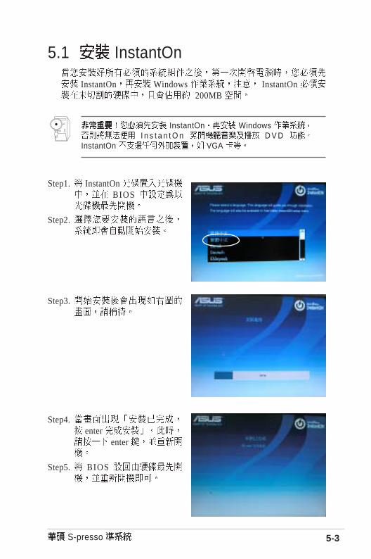
5.1 InstantOn
InstantOn Windows InstantOn 200MB
InstantOn Windows I n s t a n t O n D V D
InstantOn VGA
Step1. InstantOn BIOS
Step2.
Step4. enter
enter
Step5. BIOS
Step3.

5.2
Windows
5.3 InstantOn
InstantOn
InstantOn InstantOn
InstantOn Windows
Windows Windows Windows
Windows
InstantOn
http://www.asus.com.tw
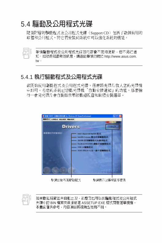
5.4 Support CD
5.4.1
BIN ASSETUP.EXE

5-6
5.4.2 Drivers menu
Intel Chipset Inf Update
INF INF
Window INF
Intel Extreme
Intel Extreme
AD1888
AD1888
Realtek RTL8100C
Realteek RTL8100C
USB 2.0
USB 2.0
ASUS UB6220

5-7 S-presso
5.4.3 Utilities menu
ASUS Live Update BIOS
Microsoft DirectX 9.0b
Microsoft DirectX 9.0b
PC-cillin 2002
PC-cillin 2002 PC-cillin
Adobe Acrobat Reader
Adobe Acrobat Reader PDF Portable DocumentFormat

5-8
5.4.4
3

5-9 S-presso
5.5 PC Probe
CPU
5.5.1 \
ASUS Utility\Probe Vx.xx Vx.xx
Show up in next execution
Tray

5-10
5.5.2
C P U
CPU
CPU
CPU
CPU

5-11 S-presso
FAT

5-12
DMI
BIOS C P U
5.5.3
CPU !!!

5-13 S-presso
5.6 5.1
5.6.1
SoundMAX SoundMAX
SoundMAX
5 . 1Multi-drive

5-14
MIDI
5.6.2

5-15 S-presso
D V D AC3 SPDIF PCM SPDIF
5.6.3
Mic2 Select