Embed Size (px)
Citation preview
S - SERIES
S - S
ER
IES
CT - 3206 - 0903/34
Brevini Power Transmission S.p.A. - 42124 REGGIO EMILIA - Italy - Via Degola,14Tel. +39 0522 9281 - Fax + 39 0522 928300 - [email protected] - www.brevini.com
1
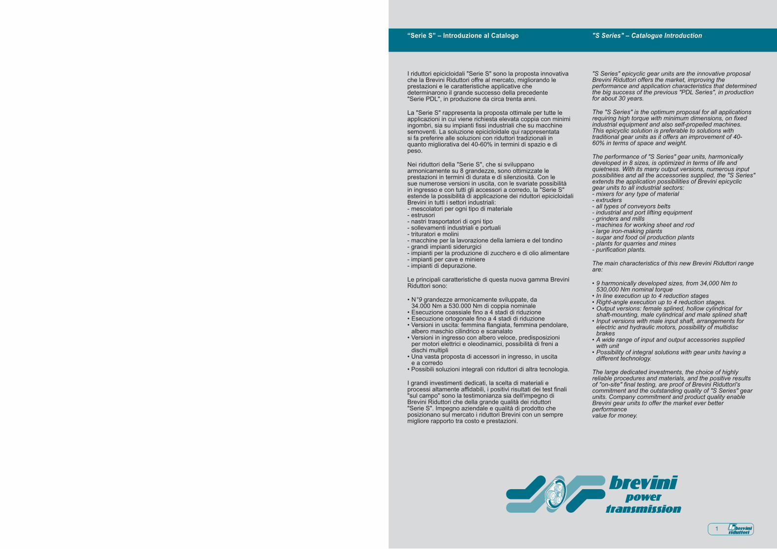
I riduttori epicicloidali "Serie S" sono la proposta innovativache la Brevini Riduttori offre al mercato, migliorando leprestazioni e le caratteristiche applicative chedeterminarono il grande successo della precedente"Serie PDL", in produzione da circa trenta anni.
La "Serie S" rappresenta la proposta ottimale per tutte leapplicazioni in cui viene richiesta elevata coppia con minimiingombri, sia su impianti fissi industriali che su macchinesemoventi. La soluzione epicicloidale qui rappresentatasi fa preferire alle soluzioni con riduttori tradizionali inquanto migliorativa del 40-60% in termini di spazio e dipeso.
Nei riduttori della "Serie S", che si sviluppanoarmonicamente su 8 grandezze, sono ottimizzate leprestazioni in termini di durata e di silenziosità. Con lesue numerose versioni in uscita, con le svariate possibilitàin ingresso e con tutti gli accessori a corredo, la "Serie S"estende la possibilità di applicazione dei riduttori epicicloidaliBrevini in tutti i settori industriali:- mescolatori per ogni tipo di materiale- estrusori- nastri trasportatori di ogni tipo- sollevamenti industriali e portuali- trituratori e molini- macchine per la lavorazione della lamiera e del tondino- grandi impianti siderurgici- impianti per la produzione di zucchero e di olio alimentare- impianti per cave e miniere- impianti di depurazione.
Le principali caratteristiche di questa nuova gamma BreviniRiduttori sono:
• N°9 grandezze armonicamente sviluppate, da 34.000 Nm a 530.000 Nm di coppia nominale• Esecuzione coassiale fino a 4 stadi di riduzione• Esecuzione ortogonale fino a 4 stadi di riduzione• Versioni in uscita: femmina flangiata, femmina pendolare, albero maschio cilindrico e scanalato• Versioni in ingresso con albero veloce, predisposizioni per motori elettrici e oleodinamici, possibilità di freni a dischi multipli• Una vasta proposta di accessori in ingresso, in uscita e a corredo• Possibili soluzioni integrali con riduttori di altra tecnologia.
I grandi investimenti dedicati, la scelta di materiali eprocessi altamente affidabili, i positivi risultati dei test finali"sul campo" sono la testimonianza sia dell'impegno diBrevini Riduttori che della grande qualità dei riduttori"Serie S". Impegno aziendale e qualità di prodotto cheposizionano sul mercato i riduttori Brevini con un sempremigliore rapporto tra costo e prestazioni.
"S Series" epicyclic gear units are the innovative proposalBrevini Riduttori offers the market, improving theperformance and application characteristics that determinedthe big success of the previous "PDL Series", in productionfor about 30 years.
The "S Series" is the optimum proposal for all applicationsrequiring high torque with minimum dimensions, on fixedindustrial equipment and also self-propelled machines.This epicyclic solution is preferable to solutions withtraditional gear units as it offers an improvement of 40-60% in terms of space and weight.
The performance of "S Series" gear units, harmonicallydeveloped in 8 sizes, is optimized in terms of life andquietness. With its many output versions, numerous inputpossibilities and all the accessories supplied, the "S Series"extends the application possibilities of Brevini epicyclicgear units to all industrial sectors:- mixers for any type of material- extruders- all types of conveyors belts- industrial and port lifting equipment- grinders and mills- machines for working sheet and rod- large iron-making plants- sugar and food oil production plants- plants for quarries and mines- purification plants.
The main characteristics of this new Brevini Riduttori rangeare:
• 9 harmonically developed sizes, from 34,000 Nm to 530,000 Nm nominal torque• In line execution up to 4 reduction stages• Right-angle execution up to 4 reduction stages.• Output versions: female splined, hollow cylindrical for shaft-mounting, male cylindrical and male splined shaft• Input versions with male input shaft, arrangements for electric and hydraulic motors, possibility of multidisc brakes• A wide range of input and output accessories supplied with unit• Possibility of integral solutions with gear units having a different technology.
The large dedicated investments, the choice of highlyreliable procedures and materials, and the positive resultsof "on-site" final testing, are proof of Brevini Riduttori'scommitment and the outstanding quality of "S Series" gearunits. Company commitment and product quality enableBrevini gear units to offer the market ever better performancevalue for money.
"S Series" – Catalogue Introduction“Serie S” – Introduzione al Catalogo
3
Die Planetengetriebe der "Serie S" sind das innovativeAngebot, das Brevini Riduttori auf dem Markt vorstellt, mitverbesserten Leistungen und Anwendungseigenschaftengegenüber der vorangehenden erfolgreichen "Serie PDL",die seit ca. dreißig Jahren gebaut wird.
Die "Serie S" ist die optimale Lösung für alle Anwendungen,die ein hohes Drehmoment bei geringen Abmessungensowohl auf ortsfesten Industrieanlagen wie auch aufselbstfahrenden Maschinen erfordern. Die hier vorgestellteLösung mit Planetengetriebe ist den konventionellenGetrieben vorzuziehen, da sie unter dem Gesichtspunktvon Platzbedarf und Gewicht eine Verbesserung von 40-60% bedeutet.
Die Getriebe der "Serie S" mit 8 aufeinander abgestimmtenGrößen weisen optimale Leistungen hinsichtlichLebensdauer und Laufruhe auf. Die "Serie S" weitet mitihren zahlreichen Abtriebsausführungen, mit denunterschiedlichsten Antriebsmöglichkeiten und demreichhaltigen Zubehör den Anwendungsbereich derPlanetengetriebe Brevini auf alle Industriesektoren aus:- Mischer für alle Materialarten- Strangpressen- Förderbänder jeder Art- Industrielle und Hafenhubwerke- Schredderanlagen und Mühlen- Maschinen zur Blech-und Rundeisenverarbeitung- Eisenhüttenwerke- Zuckerfabriken und Speiseölmühlen- Anlagen für Gruben und Bergbau- Aufbereitungsanlagen.
Die wesentlichen Merkmale der neuen Serie BreviniRiduttori sind:
• N°9 aufeinander abgestimmte Größen für Nenndrehmomente von 34.000 Nm bis 530.000 Nm• Koaxiale Ausführung mit bis zu 4 Untersetzungsstufen• Winkelantrieb mit bis zu 4 Untersetzungsstufen• Abtriebausführungen: abtriebseitige Hohlwelle oder Ausführung ohne Passfeder, zylindrischer Wellenstumpf und Keilwelle• Antriebsseitig mit Schnellgangwelle, Vorrüstung für Elektro- und Ölhydraulikmotoren, Möglichkeit für Lamellenbremsen• Ein breit gefächertes Sortiment an antriebs- und abtriebsseitigem Zubehör und als Ausstattung• Möglichkeit für integrierte Lösungen mit anderen Techniken.
Die beträchtlichen spezifischen Investitionen, dieMaterialauswahl, die äußerst zuverlässigenProduktionsprozesse und die positiven Ergebnisse derAbnahmetests "vor Ort" legen Zeugnis ab für dasEngagement der Firma Brevini Riduttori und dieerstklassige Qualität der "Serie S". Das Firmenengagementund die Güte der Produkte machen die Brevini - Getriebezu einem Spitzenprodukt auf dem Markt mit ständigverbesserem Preis-Leistungs-Verhältnis.
Les réducteurs épicycloïdaux "Série S" représentent lasolution novatrice que Brevini Riduttori apportent sur lemarché, en améliorant davantage encore les performanceset la facilité de montage qui ont été à l'origine du grandsuccès de la "Série PDL" précédente, en production depuispresque trente ans.
La "Série S" est parfaitement adaptée aux applicationsexigeant un couple de sortie élevé pour un encombrementréduit, qu'il s'agisse d'installations fixes industrielles oud'engins automoteurs. La solution épicycloïdale mise ici enoeuvre est préférable aux solutions techniques traditionnelles,du fait de son important gain de poids et d'encombrementque l'on peut évaluer à hauteur de 40 % à 60 %.
Les réducteurs de la "Série S", qui se déclinentharmonieusement en 8 grandeurs, se distinguent toutparticulièrement par leur durée de vie élevée et leurfonctionnement silencieux. Avec des nombreuses versionsen sortie, avec ses multiples solutions en entrée et avectous les accessoires fournis, la "Série S" étend le champd'application des réducteurs épicycloïdaux Brevini à tousles secteurs industriels :- mélangeurs tous types de matériaux- extrudeuses- bandes transporteuses de tous types- levage pour installations industrielles et portuaires- broyeurs et moulins- laminoirs (à acier)- grandes installations sidérurgiques- installations pour la production de sucre et d'huile alimentaire- installations pour carrières et mines- installations d'épuration
Les caractéristiques principales de cette nouvelle gammeBrevini Riduttori sont:
• 9 grandeurs judicieusement étagées, de 34 000 Nm à 530 000 Nm de couple nominal• Exécution coaxiale à 4 étages de réduction• Exécution orthogonale jusqu'à 4 étages de réduction• Versions en sortie : femelle flasquée, femelle flottante, arbre mâle cylindrique cannelé• Versions en entrée avec arbre rapide, prédispositions pour moteurs électriques et hydrauliques, avec possibilité de freins à disques multiples• Une large gamme d'accessoires fournis, en entrée, en sortie.• Combinaisons possibles avec des réducteurs d'une autre technologie.
Les importants investissements ciblés, le choix de matériauxet de procédés hautement fiables, les résultats positifs desessais finals "sur le terrain" sont autant de priorités quitémoignent de la volonté de développement de Brevini riduttoriet de recherche de la qualité. Le résultat : les réducteurs "Série S". Un effort important de mobilisation sur cet objectif et une qualité du produit qui situent sur le marché les réducteursBrevini avec un rapport coût/performances inégalable.
Los reductores epicicloidales de la "Serie S" son unainnovadora propuesta de Brevini Riduttori que por suscaracterísticas y sus prestaciones se prepara a conquistarel mercado como lo hiciera hace casi treinta años lafamosa "Serie PDL".
La "Serie S" es la solución ideal para aquellas aplicacionesfijas o móviles en las que se necesita un par elevado perono se dispone de mucho espacio. Un reductor epicicloidales entre 40 y 60% más ligero y compacto que unotradicional.
En los 8 tamaños que componen la gama se hanoptimizado la duración y la silenciosidad. Con las diferentesversiones de salidas, las entradas prácticamente infinitasy los numerosos accesorios, la "Serie S" se aplica acualquier sector industrial:- mezcladores de todo tipo de materiales- extrusores- todo tipo de cintas transportadoras- grúas de puertos, fábricas, etc.- trituradoras y molinos- líneas para fabricar chapas y varillas- grandes plantas siderúrgicas- plantas de fabricación de azúcares y aceites comestibles- cavas y minas- depuradores.
He aquí las principales características de la nueva gamade Brevini Riduttori:
• 9 tamaños, de 34.000 Nm a 530.000 Nm de par nominal• Hasta cuatro estadios de reducción en la ejecución coaxial• Hasta cuatro estadios de reducción en la ejecución ortogonal• Versiones salida: hembra embridada o pendular, eje del macho cilíndrico o acanalado• Versiones entrada: eje rápido, acople de motores eléctricos y oleodinámicos, frenos de discos múltiples• La gama más amplia de accesorios para entradas y salidas• Soluciones integradas con reductores de alta tecnología.
Las cuantiosas inversiones en I+D, la selección demateriales y procesos fiables y los resultados de losnumerosos test sobre el terreno son una prueba de nuestrocompromiso y de la calidad intrínseca de nuestrosproductos. Este compromiso con la calidad se refleja enuna relación precio/prestaciones inmejorable.
Os redutores epicicloidais da "Série S" representam a propostainovadora que a Brevini Riduttori oferece ao mercado,melhorando o desempenho e as características aplicativasque determinaram o grande sucesso da "Série PDL" anterior,em produção por aproximadamente trinta anos.
A "Série S" representa a proposta ideal para todas asaplicações nas quais é necessário um elevado torque comespaços reduzidos, seja em sistemas fixos industriais,seja em máquinas móveis. A solução epicicloidal aquirepresentada é preferível às soluções com redutorestradicionais, porque melhoram em 40 a 60% ascaracterísticas de espaço e de peso.
Nos redutores da "Série S", que se desenvolvemharmonicamente em 8 tamanhos, foi otimizado odesempenho em termos de duração e de silêncio. Comas suas numerosas versões de saída, com as váriaspossibilidades de entrada e com todos os acessóriosfornecidos, a "Série S" aumenta a possibilidade de aplicaçãodos redutores epicicloidais Brevini em todos os setoresindustriais:- misturadores para qualquer tipo de material- extrusores- fitas transportadoras de qualquer tipo- elevadores industriais e portuários- trituradores e moinhos- máquinas para a transformação de chapas e vergalhões- grandes instalações siderúrgicas- sistemas para a produção de açúcar e óleo alimentício- sistemas para pedreiras e minas- sistemas de depuração.
As principais características dessa nova linha da BreviniRiduttori são:
• N°9 tamanhos harmonicamente desenvolvidos, de 34.000 Nm a 530.000 Nm de torque nominal• Execução coaxial até 4 estágios de redução• Execução ortogonal até 4 estágios de redução• Versões de saída: fêmea flangeada, fêmea pendular, eixo macho cilíndrico e ranhurado• Versões de entrada com eixo rápido, preconfigurações para motores elétricos e oleodinâmicos, possibilidade de freios a discos múltiplos• Uma ampla oferta de acessórios de entrada, de saída e kits• Possibilidade de soluções integradas com redutores de outras tecnologias.
Os grandes investimentos dedicados, a escolha de materiais e processos altamente confiáveis, os resultados positivos dos testes finais "no campo" são o testemunho do empenho da Brevini Riduttori e da grande qualidade dos redutores da "Série S". Dedicação empresarial e qualidade de produto que posicionam os redutores Brevini no mercado com uma relação custo/benefício cada vez melhor.
"Serie S" – Introducción al Catálogo"Serie S" – Einführung zum Katalog "Série S" – Introduction "Série S" – Introdução ao catálogo
01. DESCRIZIONE RIDUTTORI DESCRIPTION OF GEAR UNITS 10
02. DESCRIZIONI TECNICHE TECHNICAL DESCRIPTIONS 12
03. ESEMPIO SELEZIONE RIDUTTORE EXAMPLE SELECTING GEAR UNIT 26
04. DATI TECNICI E TAVOLE DIMENSIONALI TECHNICAL DATA AND DIMENSIONAL DRAWINGS 31
05. USCITE - ENTRATE OUTPUT-INPUT 103
06. STATO DI FORNITURA SUPPLY CONDITION 122
07. CONDIZIONI DI STOCCAGGIO STORING CONDITION 122
08. INSTALLAZIONE INSTALLATION 124
09. GIUNTI AD ATTRITO FRICTION COUPLINGS 128
10. BRACCIO DI REAZIONE TORQUE ARM 134
11. LUBRIFICAZIONE LUBRICATION 138
IndexIndice
pagepagina
[Nm]TIPO / TYPE TN
S300 34.000 32
S400 48.000 42
S600 64.000 52
S850 90.000 62
S1200 133.000 72
S1800 190.000 78
S2500 260.000 84
S3500 370.000 90
S5000 530.000 96
Brevini NorgeBergen Office5014 BergenTel.: +47 - 5552 - 0160www.brevini.no
Brevini AustraliaVictorian OfficePreston, VIC, 3072Tel.: +61 - (03) - 9495 - 0688www.brevini.com.au
Brevini Piemonte - Valle d’Aosta10143 Torino -ItalyTel.: +39 - 011 - 7492045www.brevini.com
Brevini AustraliaWestern Australian OfficeJandakot, WA, 6164Tel.: +61 - (08) - 9417 - 1366www.brevini.com.au
Brevini IndiaChennai OfficeChennai 600083Tel.: +91 - 44 - 2221 - 1322www.breviniindia.com
Brevini AustraliaQueensland OfficeWaterford West, QLD, 4133Tel.: +61 - (07) - 3805 - 4600www.brevini.com.au
Ufficio Regionale Sicilia91025 Marsala (Trapani) - ItalyTel.: +39 - 0923 - 719721www.brevinicentrosud.it
Brevini ChinaBeijing OfficeChaoyang District100029 Beijing, ChinaTel.: +86 - 10 - 649 - 81716www.brevinichina.com
Brevini New ZealandSouth Island OfficeChristchurch 8002Tel.: +61 - (03) - 338 - 3916www.brevini.co.nz
Brevini ChinaChangsha Office410005 Changsha, Hunan Province, ChinaTel.: +86 - 731 - 441 - 1792www.brevinichina.com
Brevini Belgio S.A.B-5000 NamurTel.: +32 - 81 - 229194www.brevini.be
Ufficio Regionale Emilia Romagna e Marche40012 Lippo di Calderara di Reno (BO) - ItalyTel.: +39 - 051 - 725436www.brevinihydrosam.it
BIASETTON OLEODINAMICA S.p.A.Via Fratelli Canepa, 134A16010 Serra Riccò - GENOVATel.: +39 - 010 - 720251Fax: +39 - 010 - [email protected]
HANS MEIER AG ANTRIEBSTECHNIKIndustriestrasse 1CH - 8627 GRÜNINGEN - SWITZERLANDTel.: +41 - 1 - 9367020Fax: +41 - 1 - [email protected]
IOW TRADE Sp. z.o.o.ul. Zwolenska, 1704-761 WARSZAWA - POLANDTel.: +48 - 22 - 6158121Fax: +48 - 22 - [email protected]
NAHUM GOLDENBERG Ltd.16 Melchet St., P.O.Box 72KIRIAT - ONO 55100 - ISRAELTel.: +972 - 3 - 5347976Fax: +972 - 3 - [email protected]
K C W ETERNAL ENTERPRISE Co Ltd.No. 666, Yung-An St. 702 Tainan TAIWAN - R.O.C.Tel.: +886 - 6 - 296 - 5396Fax: +886 - 6 - 296 - [email protected]
TECNIDRA S.A.I.C.Libertad 6206 (1657) Loma HermosaBUENOS AIRES - ARGENTINATel.: +54 - 11 - 47690034Fax: +54 - 11 - [email protected]
TESPO s.r.o.Purkynova, 99612 64 BRNO - CZECH Rep.Tel.: +420 - 5 - 41242558Fax: +420 - 5 - [email protected]
Distributori esclusiviSole disctributors
Regionale BürosBureaux Régionaux Agência Regional
DelegacionesUffici regionaliRegional Offices
VertragshändlerDistributeurs exclusifs Distribuidores exclusivos
Distribuidores exclusivos
Representative office in RussiaPr. Kosmonavtov, d.47, korp.2, lit.B,Office 212196233 Saint-Petersburg, RussiaTel. +7 812 380 21 62www.brevini-russia.ru
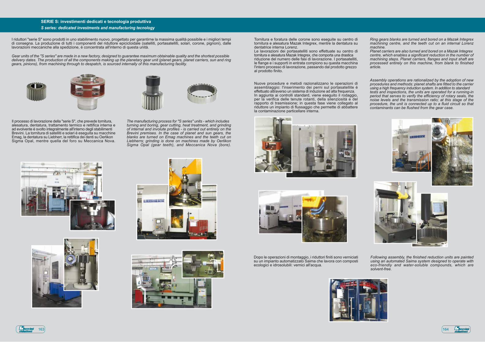
I riduttori "serie S" sono prodotti in uno stabilimento nuovo, progettato per garantirne la massima qualità possibile e i migliori tempi di consegna. La produzione di tutti i componenti del riduttore epicicloidale (satelliti, portasatelliti, solari, corone, pignoni), dalle lavorazioni meccaniche alla spedizione, é concentrata all'interno di questa unità.
Il processo di lavorazione della "serie S", che prevede tornitura, alesatura, dentatura, trattamento termico e rettifica interna e ad evolvente é svolto integralmente all'interno degli stabilimenti Brevini. La tornitura di satelliti e solari é eseguita su macchine Emag, la dentatura su Liebherr, la rettifica dei denti su Oerlikon Sigma Opal, mentre quella del foro su Meccanica Nova.
Tornitura e foratura delle corone sono eseguite su centro di tornitura e alesatura Mazak Integrex, mentre la dentatura su dentatrice interna Lorenz.Le lavorazioni dei portasatelliti sono effettuate su centro di tornitura e alesatura Mazak Integrex, che comporta una drastica riduzione del numero delle fasi di lavorazione. I portasatelliti, le flange e i supporti in entrata compiono su questa macchina l'intero processo di lavorazione, passando dal prodotto grezzo al prodotto finito.
Nuove procedure e metodi razionalizzano le operazioni di assemblaggio: l'inserimento dei perni sul portasatellite é effettuato attraverso un sistema di induzione ad alta frequenza. In aggiunta ai controlli standard, viene eseguito il rodaggio, per la verifica delle tenute rotanti, della silenziosità e del rapporto di trasmissione; in questa fase viene collegato al riduttore un impianto di flussaggio che permette di abbattere la contaminazione particellare interna.
The manufacturing process for "S series" units - which includes turning and boring, gear cutting, heat treatment, and grinding of internal and involute profiles - is carried out entirely on the Brevini premises. In the case of planet and sun gears, the blanks are turned on Emag machines and the teeth cut on Liebherrs; grinding is done on machines made by Oerlikon Sigma Opal (gear teeth), and Meccanica Nova (bore).
Ring gears blanks are turned and bored on a Mazak Integrex machining centre, and the teeth cut on an internal Lorenz machine.Planet carriers are also turned and bored on a Mazak Integrex centre, which enables a significant reduction in the number of machining steps. Planet carriers, flanges and input shaft are processed entirely on this machine, from blank to finished article.
Assembly operations are rationalized by the adoption of new procedures and methods: planet shafts are fitted to the carrier using a high frequency induction system. In addition to standard tests and inspections, the units are operated for a running-in period that serves to verify the efficiency of rotary seals, the noise levels and the transmission ratio; at this stage of the procedure, the unit is connected up to a fluid circuit so that contaminants can be flushed from the gear case.
Gear units of the "S series" are made in a new factory, designed to guarantee maximum obtainable quality and the shortest possible delivery dates. The production of all the components making up the planetary gear unit (planet gears, planet carriers, sun and ring gears, pinions), from machining through to despatch, is sourced internally of this manufacturing facility.
S series: dedicated investments and manufacturing tecnologySERIE S: investimenti dedicati e tecnologia produttiva
163 164
Dopo le operazioni di montaggio, i riduttori finiti sono verniciati su un impianto automatizzato Saima che lavora con composti ecologici e idrosolubili: vernici all'acqua.
Following assembly, the finished reduction units are painted using an automated Saima system designed to operate with eco-friendly and water-soluble compounds, which are solvent-free.
10
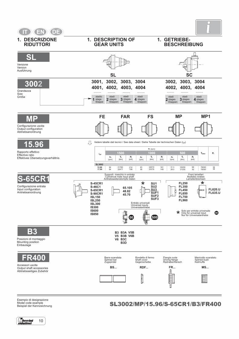
i1. DESCRIZIONE RIDUTTORI
1. DESCRIPTION OF GEAR UNITS
1. GETRIEBE- BESCHREIBUNG
SL
3002
MP
15.96
S-65CR1
B3
FR400
SL
MP
3001, 3002, 3003, 3004 3002, 3003, 30044001, 4002, 4003, 4004 4002, 4003, 4004
MP1FAR FS
SC
....... .............. .............. ..............
SU1SU2SU3SUF1SUF2SUF3
BS... RDF... FR...
B3V5V6
S-45CR1S-46C1S-65CR1S-90CR1ISL150ISL250ISL300IS300IS600IS850
65.10548.8245.70
FL250FL350FL450FL650FL750FL960
FL620.UFL635.U
V5BV6B
B3AB3BB3CB3D
SL3002/MP/15.96/S-65CR1/B3/FR400
00
1 2 23 34 4
00
00
15.96 94 214198
6356
161149
31.328.0
99 383892
7600076000
3025531255
245742537884
217602247117.86
n2 n2 n22T 2T 2T2MAXT
2P 2P 2PTPieff
[kW][kW] [rpm][rpm] [rpm] [Nm][Nm][Nm] [kW]
SL3002
n1 [rpm]
1500 1000 500
S00
MS...
FE
Versione Version Ausführung
stadio stage Etappe
stadi stages Etappen
stadi stages Etappen
stadi stages Etappen
stadi stages Etappen
stadi stages Etappen
stadi stages Etappen
Grandezza Size Größe
Configurazione uscita Output configuration Abtriebsanordnung
Rapporto effettivo Effective ratio Effektives Übersetzungsverhältnis
Configurazione entrata Input configuration Antriebsanordnung
Posizioni di montaggio Mounting position Einbaulage
Accessori uscita Output shaft accessories Abtriebsseitiges Zubehör
Vedere tabelle dati tecnici / See data sheet / Siehe Tabelle der technischen Daten (ieff)
Supporti maschio in entrata Cylindrical male input shaft
Antriebswellenstümpfe Daten
Freni lamellari Multidisc brakes
Lamellenbremsen
Entrate universali Universal inputs Universalantriebe
Solo per entrata universale Only for universal input Nur für Universalantriebe
Esempio di designazione Model code example Beispiel der Kennzeichnung
Barra scanalata Splined bar Zugspindel
Rondella di fermo Shaft cover Gegenscheibe
Flangia ruota Driving flange Radnabenflansch
Manicotto scanalato Splined bush Keilmuffe

12
i2. TECHNICAL DESCRIPTIONS
Reduction ratio ieffIt represents the ratio between gear unit input and output speed. The modularity of the Brevini Riduttori range offers the availability of other ratios in addition to those given: consult Brevini Riduttori for the availability of further ratios.
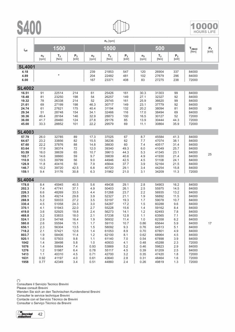
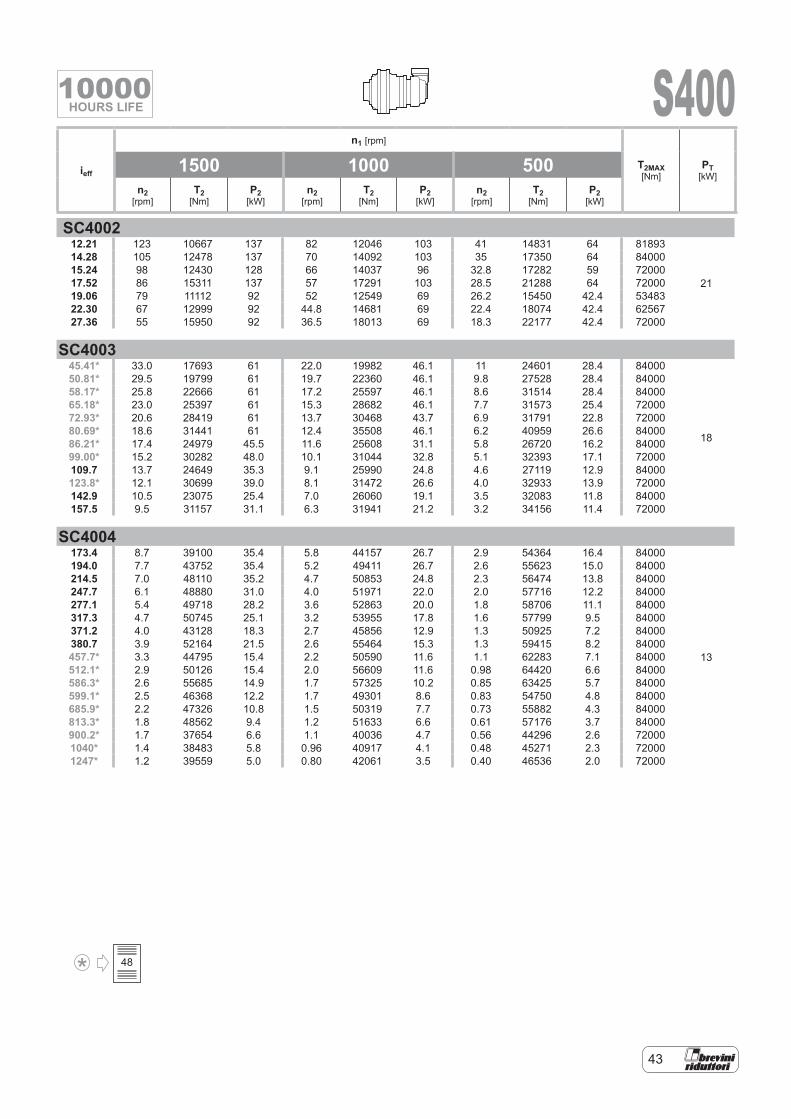
Output torque T2 [Nm]Gear unit output torque referred to 10000 hours of operation, calculated according to I.S.O. (D.P. 6336).This value (application factor equal to 1) is given for gear units with inline and right-angle versions according to the dif-ferent input speeds.
Max. torque T2MAX [Nm]Max. permissible output torque, as peak or for short periods.For drives involving a high number of starts or reversals, also the max.operational torque must be opportunely limited according to the fatigue resis-tance of the gears or shafts.
Nominal torque TN [Nm]The conventional torque characterizing the size of the gear unit.It corresponds to the limit torque accord-ing to I.S.O. (P.D. 6336) of the strongest ratio of each size.
Nominal power P2 [kW]A combination of the torque value rele-vant to a duration of 10000 h at the rela-tive gear unit output speed.For right-angle units the above values re-fer to a version with universal input.In those cases when the nominal power value in the application considered ex-ceeds the relevant gear unit thermal rat-ing, a special auxiliary oil cooling circuit must be provided.
Thermal rating PT [kW]The power that can be transmitted con-tinuously by the gear unit, in given op-erating conditions, relevant to the max. permissible temperatures for the gear unit. See chapter: Thermal rating.
Input speed n1 [rpm]The catalogue gives three input speed values to cover the majority of applica-tions in the industrial sector.
2. DESCRIZIONI TECNICHE
Rapporto di riduzione ieffRappresenta la relazione fra la velocità in ingresso n1 ed uscita del riduttore n2. La modularità della gamma proposta da Brevini Riduttori permette la disponibilità di altri rapporti oltre a quelli indicati: con-sultare Brevini Riduttori per la eventuale disponibilità di ulteriori rapporti.
Coppia in uscita T2 [Nm]Valore della coppia in uscita riduttore riferita ad una durata di 10.000 ore di funzionamento, calcolata secondo I.S.O. (D.P. 6336). Tale valore (fattore di appli-cazione uguale ad 1) è indicato sia per i riduttori con versione in linea che an-golari in relazione alle diverse velocità in ingresso.
Coppia massima T2MAX [Nm]Coppia massima d’uscita ammissi-bile, come punta o per brevi durate. Per azionamenti che comportano un ele-vato numero di avviamenti o inversioni, anche la coppia massima di impiego deve essere opportunamente limitata in relazione alla resistenza degli ingranaggi o degli alberi.
Coppia nominale TN [Nm]E’ la coppia convenzionale che caratte-rizza la grandezza del riduttore. Trova corrispondenza nella coppia limite se-condo I.S.O. (D.P. 6336) del rapporto più forte di ogni grandezza.
Potenza in uscita P2 [kW]Combinazione del valore di coppia re-lativo ad una durata di 10000 h alla re-lativa velocità in uscita riduttore. Per le versioni angolari i suddetti valori fanno riferimento ad una versione con ingresso universale. Nei casi in cui il valore della potenza nominale nell’applicazione con-siderata superi il valore della potenza termica del riduttore in oggetto, occorre prevedere un apposito circuito ausiliario di raffreddamento dell’olio.
Potenza termica PT [kW]Potenza che può essere trasmessa in continuo dal riduttore, in determinate condizioni di funzionamento, relativa-mente alle massime temperature ammis-sibili per il riduttore. Vedere il capitolo: Potenza termica.
Velocità in ingresso n1 [rpm]I valori di velocità in ingresso indicati nel catalogo sono tre per coprire la maggior parte delle applicazioni del settore indu-striale.
2. TECHNISCHE BESCHREIBUNGEN
Übersetzungzverhältnis ieffStellt das Verhältnis zwischen Antriebs-drehzahl n1 und Abtriebsdrehzahl n2 dar. Das Baukastensystem der Brevini Ridut-tori Getriebe bietet neben den aufgeführ-ten weitere Übersetzungsverhältnisse an: wenden Sie sich an Brevini Riduttori für Auskünfte über weitere verfügbare Übersetzungsverhältnisse.
Abtriebsdrehzahl T2 [Nm]Wert der Abtriebsdrehzahl des Getriebes bezogen auf eine Dauer von 10.000 Be-triebsstunden, berechnet laut I.S.O. (D.P. 6336).Dieser Wert (Anwendungsfaktor gleich 1) gilt sowohl für In-Line- wie auch für die Winkelgetriebe entsprechend den ver-schiedenen Antriebsdrehzahlen.
Maximales Drehmoment T2MAX [Nm]Maximal zulässiges Abtriebsdrehmo-ment, sowohl als Spitze wie auch für kur-ze Dauer. Bei Antrieben mit einer hohen Anzahl von Starts oder Umsteuerungen muss auch das maximale Betriebsdreh-moment entsprechend der Ermüdungs-beständigkeit der Zahnräder oder Wellen begrenzt werden.
Nenndrehmoment TN [Nm]Das konventionelle Drehmoment, das die Getriebegröße bezeichnet. Es entspricht dem Grenzdrehmoment laut I.S.O. (D.P. 6336) des höchsten Drehmomentver-hältnisses jeder Größe.
Abtriebsleistung P2 [kW]Kombination des Drehmomentwerts für eine Dauer von 10000 Stunden mit der Abtriebsdrehzahl des Getriebes. Bei Winkelgetrieben beziehen sich die Werte auf eine Ausführung mit Universalantrieb. Bei allen Fällen, in denen die Nennleis-tung bei der in Betracht gezogenen An-wendung den Wert der Wärmeleistung des Getriebes übertrifft, muss ein geeig-netes zusätzliches Kühlsystem installiert werden.
Wärmeleistung PT [kW]Leistung, die kontinuierlich vom Getriebe unter bestimmten Betriebsbedingungen abgegeben werden kann in Bezug auf die für das Getriebe zulässigen Höchst-temperaturen. Siehe Kapitel: Wärmeleis-tung.
Antriebsdrehzahl n1 [rpm]Die drei im Katalog angegebenen Wer-te der Antriebsdrehzahlen decken den größten Teil der Anwendungen des In-dustriebereichs ab.
14
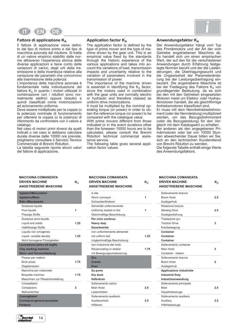
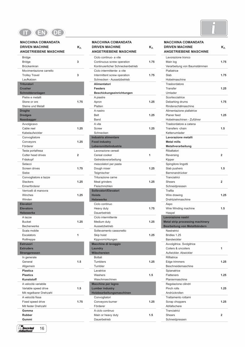
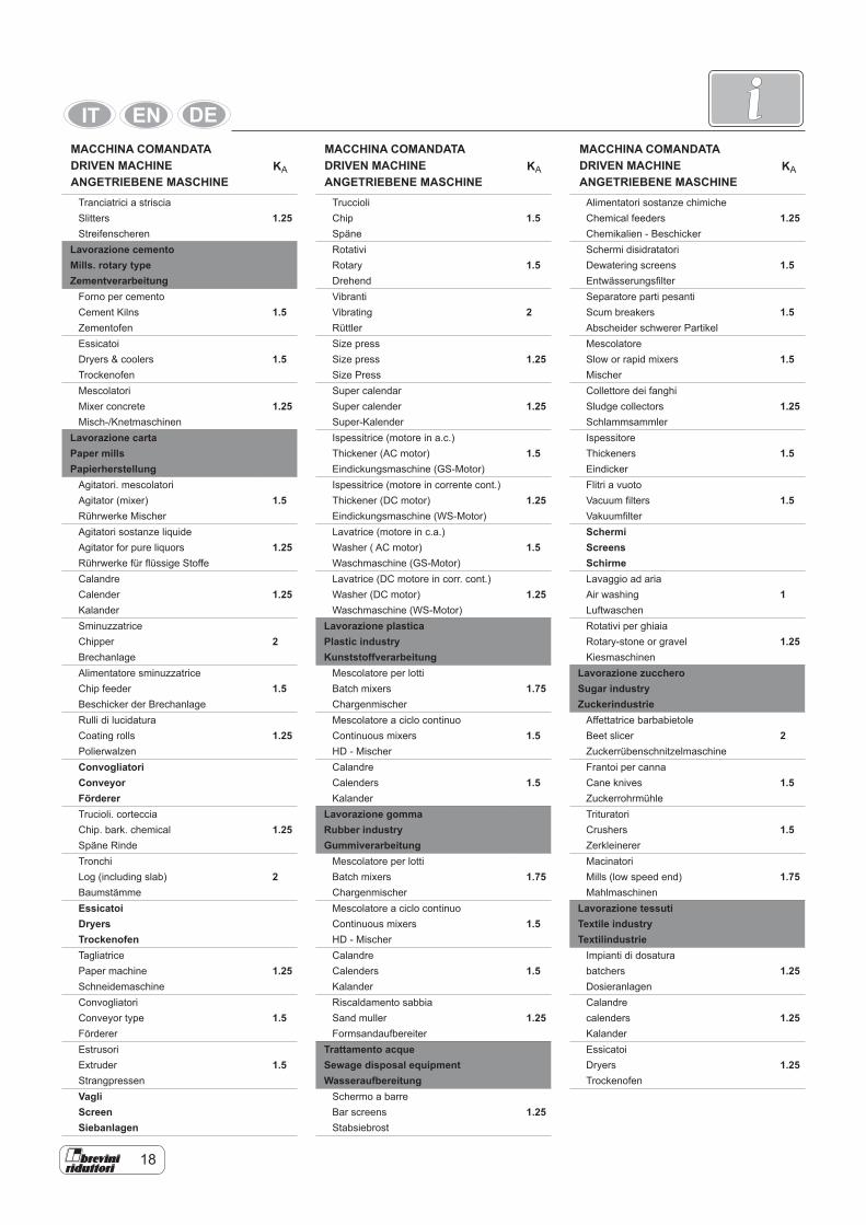
iApplication factor KAThe application factor is defined by the type of prime mover and the type of ma-chine driven by the gear unit. This is an empirical value fixed by the standards through the historic experience of the various applications and takes into ac-count the variations of load, transmission impacts and uncertainty relative to the variation of parameters involved in the transmission of power.The importance of the machine driven is essential in identifying the KA factor, since the motors used in combination with the gear units are normally electric or hydraulic and therefore classed as uniform drive motorizations.It must be multiplied by the nominal op-erating torque (or power) in order to ob-tain the reference torque (or power) to be compared with the catalogue value.With prime movers different from those indicated or in the event durations other than the foreseen 10000 hours are to be calculated, please consult the Brevini Riduttori technical commercial assis-tance service.The following table gives several appli-cation factor values.
Agitatori/MescolatoriAgitators/MixerRühr-/Mischwerke
Sostanze liquidePure liquids 1Flüssige StoffeSostanze semi-liquideLiquid and solids 1.25Halbflüssige StoffeLiquido non omogeneoLiquid- variable density 1.25Nicht homogene Flüssigkeiten
Lavorazione pietra ed argillaClay working machineStein- und Tonverarbeitung
Presse per mattoniBrick press 1.75ZiegelpressenMacchina per mattonelleBriquette machine 1.75Maschinen zur FliesenherstellungCompattatoriCompactors 2Müllverdichter
ConvogliatoriConveyors-general pourposeFörderer
A viteWorm conveyor 1SchneckenfördererAlimentati uniformementeUniformly loaded or fed 1Gleichmäßige BeschickungPer ciclo continuoHeavy dutyDauerbetriebnon uniformemente alimentati not uniform fed 1.25Ungleichmäßige Beschickungcon inversione del motoReciprocating or shaker 1.75mit BewegungsumsteuerungGruCranesKranDa portoDry dockHafenkranSollevamento caricoMain Hoist 2.5LastenhebenSollevamento ausiliarioAuxiliaryHoist 2.5Hilfskran
Sollevamento braccioBoom Hoist 2.5AuslegerhubRotazione braccioSlewing Drive 2.5AuslegerdrehungTraslazione gruTraction Drive 3KranbewegungContainerContainerContainerSollevamento containerMain Hoist 3Container - HebenSollevamento braccioBoom Hoist 2AuslegerhubApplicazione industrialeIndustrial DutyIndustrieanwendungSollevamento principaleMain 2.5HaupthebezeugeSollevamento ausiliarioAuxiliary 2.5Hilfshebezeuge
MACCHINA COMANDATADRIVEN MACHINE KAANGETRIEBENE MASCHINE
MACCHINA COMANDATADRIVEN MACHINE KAANGETRIEBENE MASCHINE
MACCHINA COMANDATADRIVEN MACHINE KAANGETRIEBENE MASCHINE
Fattore di applicazione KAIl fattore di applicazione viene defini-to dal tipo di motore primo e dal tipo di macchina azionata dal riduttore. Si tratta di un valore empirico stabilito dalle nor-me attraverso l’esperienza storica delle diverse applicazioni e tiene conto delle variazioni di carico, degli urti della tra-smissione e della incertezza relative alla variazione dei parametri che concorrono alla trasmissione della potenza.L’importanza della macchina azionata è fondamentale nella individuazione del fattore KA in quanto i motori utilizzati in combinazione con i riduttori sono nor-malmente elettrici oppure idraulici e quindi classificati come motorizzazioni ad azionamento uniforme.Deve essere moltiplicato per la coppia (o la potenza) nominale di funzionamento per ottenere la coppia (o la potenza) di riferimento da confrontare con il valore a catalogo.Nel caso di motori primi diversi da quelli indicati o nel caso si debbano calcolare durate diverse dalle 10000 ore previste, preghiamo consultare il Servizio Tecnico Commerciale di Brevini Riduttori.La tabella seguente riporta alcuni valori del fattore di applicazione.
Anwendungsfaktor KADer Anwendungsfaktor hängt vom Typ des Primärmotors und der Art der vom Getriebe angetriebenen Maschine ab. Es handelt sich um einen empirischen Wert, der auf den für die verschiedenen Anwendungen durch Erfahrung festge-legte Normen beruht und der die Lastän-derungen, die Übertragungswucht und die Ungewissheit der Parameterände-rung bei der Leistungsübertragung ein-bezieht. Die angetriebene Maschine ist bei der Festlegung des Faktors KA von grundlegender Bedeutung, da es sich bei den mit den Getrieben eingesetzten Motoren meist um Elektro- oder Hydrau-likmotoren handelt, die als gleichförmige Antriebsmotoren klassifiziert sind.Er muss mit dem Nennbetriebsdrehmo-ment (oder der Nennleistung) multipliziert werden, um das Bezugsdrehmoment (oder die Bezugsleistung) für den Ver-gleich mit dem Katalogwert zu erhalten.Bei anderen als den angegebenen Pri-märmotoren oder bei von 10000 Stun-den abweichender Dauer bitten wir Sie, sich an den technischen Kundendienst von Brevini Riduttori zu wenden.Die folgende Tabelle enthält einige Werte des Anwendungsfaktors.
16
iBridgeBridge 3BrückenkranMovimentazione carrelloTrolley Travel 3Laufkatzen
TrituratoriCrusherSchredderanlagen
Pietre e metalliStone or ore 1.75Steine und Metall
DragheDredgesNassbagger
AvvolgicavoCable reel 1.25KabelaufwicklerConvogliatoreConveyors 1.25FördererTesta portafresaCutter head drives 2FräskopfSetacciScreen drives 1.75SiebeConvogliatore a tazzeStackers 1.25EimerfördererVerricelli di manovraWinches 1.25Winden
ElevatoriElevatorsHebewerke
A tazzeBucket 1.25BecherwerkeScala mobileEscalators 1Rolltreppe
EstrusoriExtruders Strangpressen
In generaleGeneral 1.5AllgemeinPlasticaPlasticsKunststoffA velocità variabileVariable speed drive 1.5Mit regelbarer DrehzahlA velocità fissaFixed speed drive 1.75Mit fester DrehzahlGommaRubberGummi
Ciclo continuo- a viteContinuous screw operation 1.75Kontinuierlicher SchneckenbetriebCiclo intermittente- a viteIntermittent screw operation 1.75Schnecken - AussetzbetriebAlimentatoriFeedersBeschickungseinrichtungen A piastreApron 1.25PlattenA nastroBelt 1.25BandA viteScrew 1.25Schnecken
Industria alimentareFood industryLebensmittelindustrie
Lavorazione cerealiCereal cooker 1Getreideverarbeitungmescolatori per pastaDough mixer 1.25TeigmischerTriturazione carneMeat grinders 1.25Fleischmühlen
Sollevatori/ElevatoriHoistsHebewerke
Ciclo continuoHeavy duty 1.75DauerbetriebCiclo intermittenteMedium duty 1.25AussetzbetriebSollevamento cassonettoSkip hoist 1.25Kippvorrichtungen
Macchine di lavaggioLaundryWäschereien
BottaliTumblers 1.25TumblerLavatriceWashers 1.5Waschmaschinen
Macchine per legnoLumber industryHolzbearbeitungsmaschinen
ConvogliatoriConveyors-burner 1.25FördererA ciclo continuoMain or heavy duty 1.5Dauerbetrieb
Lavorazione troncoMain log 1.75Verarbeitung von BaumstämmenPiallatriceSlab 1.75HobelmaschineTrasbordatoreTransfer 1.25UmladerScortecciatriceDebarking drums 1.75RindenschälmaschineAlimentazione piallatricePlaner feed 1.25Hobelmaschinen - ZuführerTrasbordatore a catenaTransfers -chain 1.5KettenumladerLavorazione metalliMetal millsMetallverarbeitungRibaltatoriReversing 2KipperSpingitore lingottiSlab pushers 1.5BarrenandrückerTranciatriciShears 2SchneidpressenTrafilaWire drawing 1.25DrahtziehmaschineAspoWire Winding machine 1.5Haspel
Lavorazione nastriMetal strip processing machineryBearbeitung von Metallbändern
NastratriciBridles 1.25BandwicklerAvvolgitrice. SvolgitriceCoilers & uncoilers 1Aufwickler. AbwicklerRifilatriceEdge trimmers 1.25BeschneidemaschineSpianatriceFlatteners 1.25PlaniermaschineRegolazione cilindriPinch rolls 1.25AndrückrollenTrattamento rottamiScrap choppers 1.25AbfallschereTranciatriciShears 2Schneidpressen
MACCHINA COMANDATADRIVEN MACHINE KAANGETRIEBENE MASCHINE
MACCHINA COMANDATADRIVEN MACHINE KAANGETRIEBENE MASCHINE
MACCHINA COMANDATADRIVEN MACHINE KAANGETRIEBENE MASCHINE
18
iTranciatrici a strisciaSlitters 1.25Streifenscheren
Lavorazione cementoMills. rotary typeZementverarbeitung
Forno per cementoCement Kilns 1.5ZementofenEssicatoiDryers & coolers 1.5TrockenofenMescolatoriMixer concrete 1.25Misch-/Knetmaschinen
Lavorazione cartaPaper millsPapierherstellung
Agitatori. mescolatoriAgitator (mixer) 1.5Rührwerke MischerAgitatori sostanze liquideAgitator for pure liquors 1.25Rührwerke für flüssige StoffeCalandreCalender 1.25KalanderSminuzzatriceChipper 2BrechanlageAlimentatore sminuzzatriceChip feeder 1.5Beschicker der BrechanlageRulli di lucidaturaCoating rolls 1.25PolierwalzenConvogliatoriConveyorFördererTrucioli. cortecciaChip. bark. chemical 1.25Späne RindeTronchiLog (including slab) 2BaumstämmeEssicatoiDryersTrockenofenTagliatricePaper machine 1.25SchneidemaschineConvogliatoriConveyor type 1.5FördererEstrusoriExtruder 1.5StrangpressenVagliScreenSiebanlagen
TruccioliChip 1.5SpäneRotativiRotary 1.5DrehendVibrantiVibrating 2RüttlerSize pressSize press 1.25Size PressSuper calendarSuper calender 1.25Super-KalenderIspessitrice (motore in a.c.)Thickener (AC motor) 1.5Eindickungsmaschine (GS-Motor)Ispessitrice (motore in corrente cont.)Thickener (DC motor) 1.25Eindickungsmaschine (WS-Motor)Lavatrice (motore in c.a.)Washer ( AC motor) 1.5Waschmaschine (GS-Motor)Lavatrice (DC motore in corr. cont.)Washer (DC motor) 1.25Waschmaschine (WS-Motor)
Lavorazione plasticaPlastic industryKunststoffverarbeitung
Mescolatore per lottiBatch mixers 1.75ChargenmischerMescolatore a ciclo continuoContinuous mixers 1.5HD - MischerCalandreCalenders 1.5Kalander
Lavorazione gommaRubber industryGummiverarbeitung
Mescolatore per lottiBatch mixers 1.75ChargenmischerMescolatore a ciclo continuoContinuous mixers 1.5HD - MischerCalandreCalenders 1.5KalanderRiscaldamento sabbiaSand muller 1.25Formsandaufbereiter
Trattamento acqueSewage disposal equipmentWasseraufbereitung
Schermo a barreBar screens 1.25Stabsiebrost
Alimentatori sostanze chimicheChemical feeders 1.25Chemikalien - BeschickerSchermi disidratatoriDewatering screens 1.5EntwässerungsfilterSeparatore parti pesantiScum breakers 1.5Abscheider schwerer PartikelMescolatoreSlow or rapid mixers 1.5MischerCollettore dei fanghiSludge collectors 1.25SchlammsammlerIspessitoreThickeners 1.5EindickerFlitri a vuotoVacuum filters 1.5VakuumfilterSchermiScreensSchirmeLavaggio ad ariaAir washing 1LuftwaschenRotativi per ghiaiaRotary-stone or gravel 1.25Kiesmaschinen
Lavorazione zuccheroSugar industryZuckerindustrie
Affettatrice barbabietoleBeet slicer 2ZuckerrübenschnitzelmaschineFrantoi per cannaCane knives 1.5ZuckerrohrmühleTrituratoriCrushers 1.5ZerkleinererMacinatoriMills (low speed end) 1.75Mahlmaschinen
Lavorazione tessutiTextile industryTextilindustrie
Impianti di dosaturabatchers 1.25DosieranlagenCalandrecalenders 1.25KalanderEssicatoiDryers 1.25Trockenofen
MACCHINA COMANDATADRIVEN MACHINE KAANGETRIEBENE MASCHINE
MACCHINA COMANDATADRIVEN MACHINE KAANGETRIEBENE MASCHINE
MACCHINA COMANDATADRIVEN MACHINE KAANGETRIEBENE MASCHINE
20
i
Avviamenti orari / Starts per hour / Starts pro Stunde
1-5 6-25 26-100 101-200Cs 1 1.05 1.15 1.25
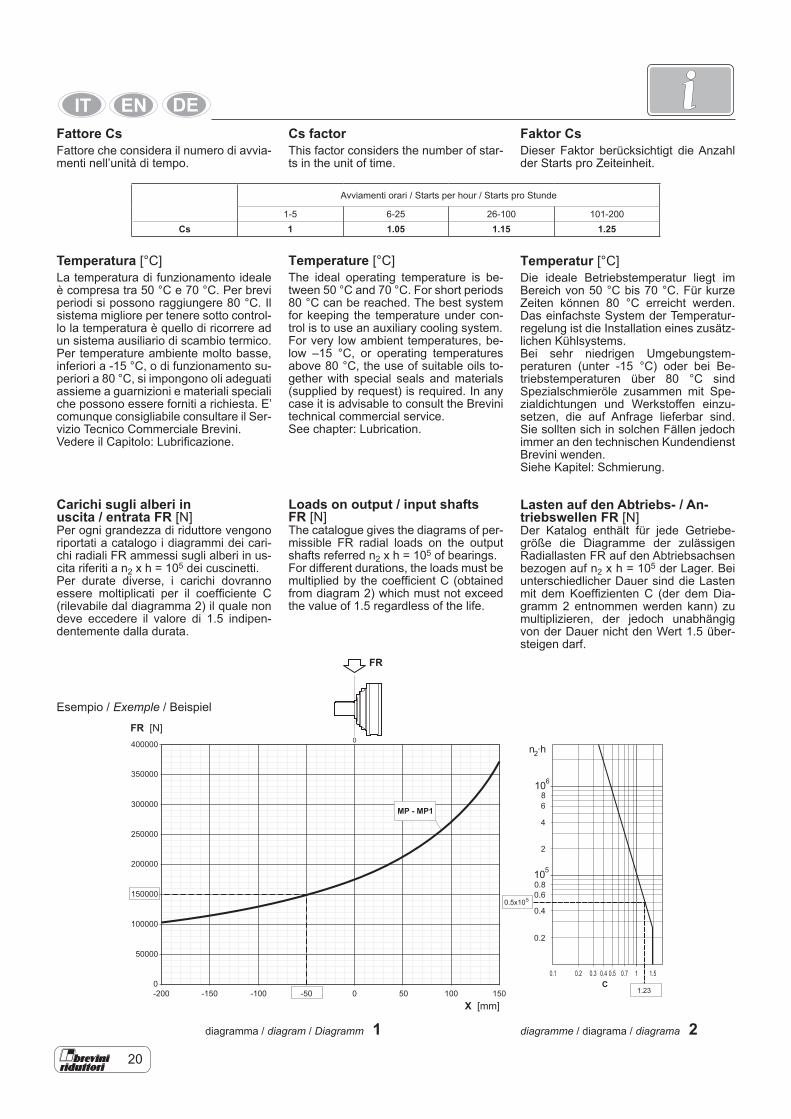
Fattore CsFattore che considera il numero di avvia-menti nell’unità di tempo.
Temperatura [°C]La temperatura di funzionamento ideale è compresa tra 50 °C e 70 °C. Per brevi periodi si possono raggiungere 80 °C. Il sistema migliore per tenere sotto control-lo la temperatura è quello di ricorrere ad un sistema ausiliario di scambio termico.Per temperature ambiente molto basse, inferiori a -15 °C, o di funzionamento su-periori a 80 °C, si impongono oli adeguati assieme a guarnizioni e materiali speciali che possono essere forniti a richiesta. E’ comunque consigliabile consultare il Ser-vizio Tecnico Commerciale Brevini.Vedere il Capitolo: Lubrificazione.
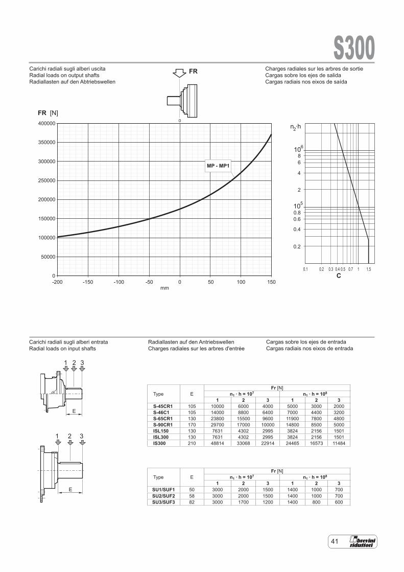
Carichi sugli alberi in uscita / entrata FR [N]Per ogni grandezza di riduttore vengono riportati a catalogo i diagrammi dei cari-chi radiali FR ammessi sugli alberi in us-cita riferiti a n2 x h = 105 dei cuscinetti.Per durate diverse, i carichi dovranno essere moltiplicati per il coefficiente C (rilevabile dal diagramma 2) il quale non deve eccedere il valore di 1.5 indipen-dentemente dalla durata.
Faktor CsDieser Faktor berücksichtigt die Anzahl der Starts pro Zeiteinheit.
Temperatur [°C]Die ideale Betriebstemperatur liegt im Bereich von 50 °C bis 70 °C. Für kurze Zeiten können 80 °C erreicht werden. Das einfachste System der Temperatur-regelung ist die Installation eines zusätz-lichen Kühlsystems.Bei sehr niedrigen Umgebungstem-peraturen (unter -15 °C) oder bei Be-triebstemperaturen über 80 °C sind Spezialschmieröle zusammen mit Spe-zialdichtungen und Werkstoffen einzu-setzen, die auf Anfrage lieferbar sind. Sie sollten sich in solchen Fällen jedoch immer an den technischen Kundendienst Brevini wenden.Siehe Kapitel: Schmierung.
Lasten auf den Abtriebs- / An-triebswellen FR [N]Der Katalog enthält für jede Getriebe-größe die Diagramme der zulässigen Radiallasten FR auf den Abtriebsachsen bezogen auf n2 x h = 105 der Lager. Bei unterschiedlicher Dauer sind die Lasten mit dem Koeffizienten C (der dem Dia-gramm 2 entnommen werden kann) zu multiplizieren, der jedoch unabhängig von der Dauer nicht den Wert 1.5 über-steigen darf.
Cs factorThis factor considers the number of star-ts in the unit of time.
Temperature [°C]The ideal operating temperature is be-tween 50 °C and 70 °C. For short periods 80 °C can be reached. The best system for keeping the temperature under con-trol is to use an auxiliary cooling system.For very low ambient temperatures, be-low –15 °C, or operating temperatures above 80 °C, the use of suitable oils to-gether with special seals and materials (supplied by request) is required. In any case it is advisable to consult the Brevini technical commercial service.See chapter: Lubrication.
Loads on output / input shafts FR [N]The catalogue gives the diagrams of per-missible FR radial loads on the output shafts referred n2 x h = 105 of bearings.For different durations, the loads must be multiplied by the coefficient C (obtained from diagram 2) which must not exceed the value of 1.5 regardless of the life.
n ·h
10
10
2
6
5
8
6
4
2
0.8
0.6
0.4
0.2
0.20.1 0.3 0.4 0.5 0.7 1 1.5
400000
350000
300000
250000
200000
150000
100000
50000
0
-200 -150 -100 -50 0 50 100 150
0
C
MP - MP1
FR [N]
X [mm]
FR
1.23
0.5x10⁵
diagramma / diagram / Diagramm 1 diagramme / diagrama / diagrama 2
Esempio / Exemple / Beispiel
22
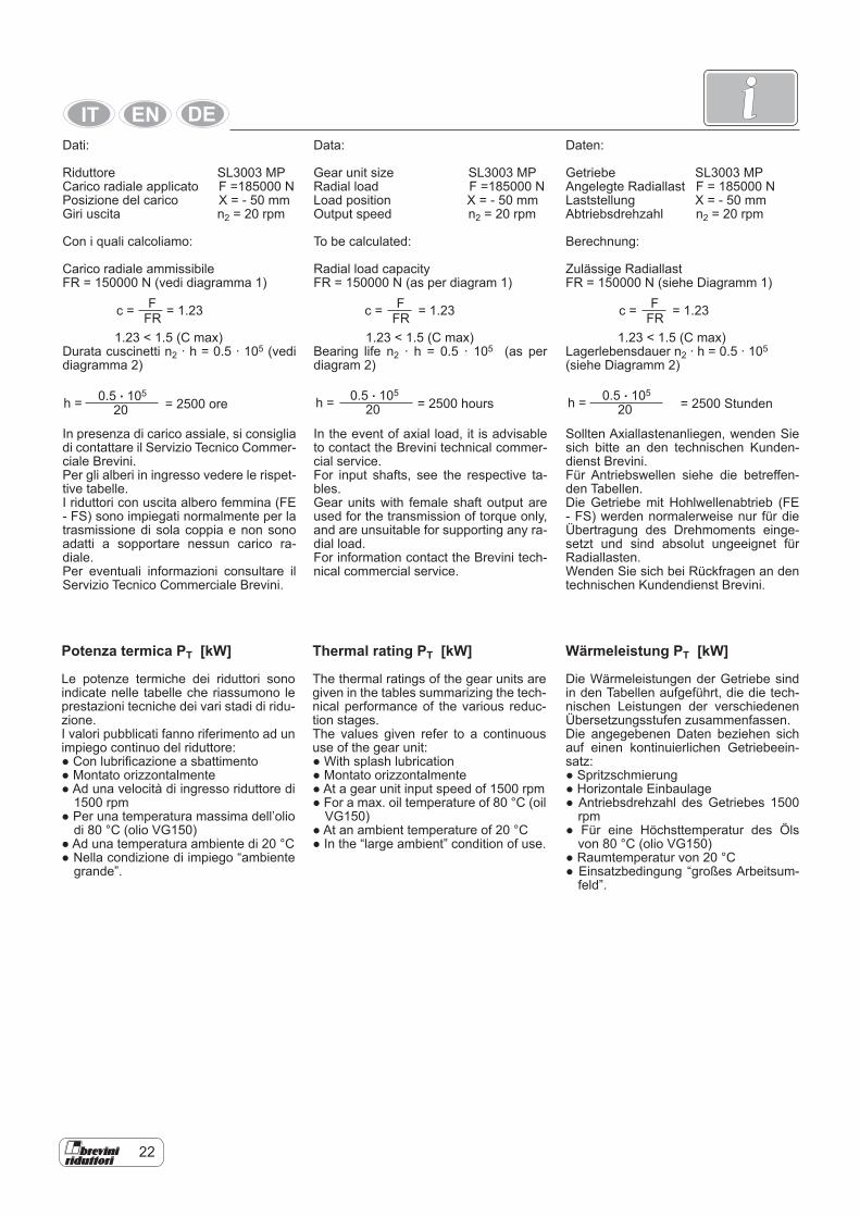
iDati:
Riduttore SL3003 MPCarico radiale applicato F =185000 NPosizione del carico X = - 50 mmGiri uscita n2 = 20 rpm
Con i quali calcoliamo:
Carico radiale ammissibileFR = 150000 N (vedi diagramma 1)
1.23 < 1.5 (C max)Durata cuscinetti n2 · h = 0.5 · 105 (vedi diagramma 2)
In presenza di carico assiale, si consiglia di contattare il Servizio Tecnico Commer-ciale Brevini.Per gli alberi in ingresso vedere le rispet-tive tabelle.I riduttori con uscita albero femmina (FE - FS) sono impiegati normalmente per la trasmissione di sola coppia e non sono adatti a sopportare nessun carico ra-diale.Per eventuali informazioni consultare il Servizio Tecnico Commerciale Brevini.
0.5 . 105
20h = = 2500 ore
Potenza termica PT [kW]
Le potenze termiche dei riduttori sono indicate nelle tabelle che riassumono le prestazioni tecniche dei vari stadi di ridu-zione.I valori pubblicati fanno riferimento ad un impiego continuo del riduttore: ● Con lubrificazione a sbattimento● Montato orizzontalmente● Ad una velocità di ingresso riduttore di
1500 rpm● Per una temperatura massima dell’olio
di 80 °C (olio VG150)● Ad una temperatura ambiente di 20 °C● Nella condizione di impiego “ambiente
grande”.
Daten:
Getriebe SL3003 MPAngelegte Radiallast F = 185000 NLaststellung X = - 50 mmAbtriebsdrehzahl n2 = 20 rpm Berechnung:
Zulässige RadiallastFR = 150000 N (siehe Diagramm 1)
1.23 < 1.5 (C max)Lagerlebensdauer n2 · h = 0.5 · 105
(siehe Diagramm 2)
Sollten Axiallastenanliegen, wenden Sie sich bitte an den technischen Kunden-dienst Brevini.Für Antriebswellen siehe die betreffen-den Tabellen. Die Getriebe mit Hohlwellenabtrieb (FE - FS) werden normalerweise nur für die Übertragung des Drehmoments einge-setzt und sind absolut ungeeignet für Radiallasten.Wenden Sie sich bei Rückfragen an den technischen Kundendienst Brevini.
Wärmeleistung PT [kW]
Die Wärmeleistungen der Getriebe sind in den Tabellen aufgeführt, die die tech-nischen Leistungen der verschiedenen Übersetzungsstufen zusammenfassen.Die angegebenen Daten beziehen sich auf einen kontinuierlichen Getriebeein-satz: ● Spritzschmierung● Horizontale Einbaulage● Antriebsdrehzahl des Getriebes 1500
rpm● Für eine Höchsttemperatur des Öls
von 80 °C (olio VG150)● Raumtemperatur von 20 °C● Einsatzbedingung “großes Arbeitsum-
feld”.
FFRc = = 1.23
0.5 . 105
20h = = 2500 Stunden
Data:
Gear unit size SL3003 MPRadial load F =185000 NLoad position X = - 50 mmOutput speed n2 = 20 rpm
To be calculated:
Radial load capacityFR = 150000 N (as per diagram 1)
1.23 < 1.5 (C max)Bearing life n2 · h = 0.5 · 105 (as per diagram 2)
In the event of axial load, it is advisable to contact the Brevini technical commer-cial service.For input shafts, see the respective ta-bles. Gear units with female shaft output are used for the transmission of torque only, and are unsuitable for supporting any ra-dial load.For information contact the Brevini tech-nical commercial service.
0.5 . 105
20h = = 2500 hours
Thermal rating PT [kW]
The thermal ratings of the gear units are given in the tables summarizing the tech-nical performance of the various reduc-tion stages.The values given refer to a continuous use of the gear unit: ● With splash lubrication● Montato orizzontalmente● At a gear unit input speed of 1500 rpm● For a max. oil temperature of 80 °C (oil
VG150)● At an ambient temperature of 20 °C● In the “large ambient” condition of use.
FFRc = = 1.23 F
FRc = = 1.23
24
i
Ore di lavoro gionaliereHours of work per dayArbeitsstunden pro Tag
Temperatura ambiente / Ambient temperature / Umgebungstemperatur [°C]
10° 20° 30° 40° 50°≥10 1.15 1 0.85 0.7 0.68 1.25 1.1 1 0.85 0.76 1.4 1.25 1.1 1 0.854 1.6 1.4 1.25 1.1 12 1.8 1.6 1.4 1.25 1.1
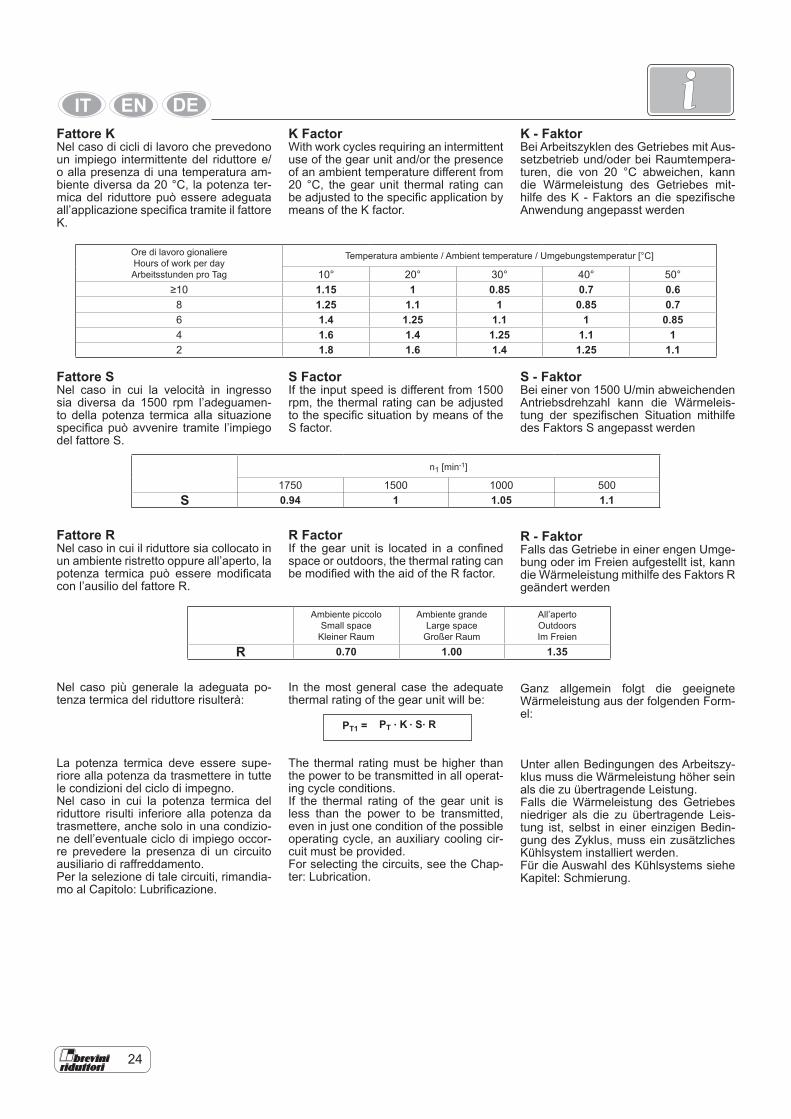
Fattore KNel caso di cicli di lavoro che prevedono un impiego intermittente del riduttore e/o alla presenza di una temperatura am-biente diversa da 20 °C, la potenza ter-mica del riduttore può essere adeguata all’applicazione specifica tramite il fattore K.
Fattore SNel caso in cui la velocità in ingresso sia diversa da 1500 rpm l’adeguamen-to della potenza termica alla situazione specifica può avvenire tramite l’impiego del fattore S.
n1 [min-1]
1750 1500 1000 500S 0.94 1 1.05 1.1
Ambiente piccoloSmall space
Kleiner Raum
Ambiente grandeLarge space
Großer Raum
All’apertoOutdoorsIm Freien
R 0.70 1.00 1.35
Fattore RNel caso in cui il riduttore sia collocato in un ambiente ristretto oppure all’aperto, la potenza termica può essere modificata con l’ausilio del fattore R.
Nel caso più generale la adeguata po-tenza termica del riduttore risulterà:
La potenza termica deve essere supe-riore alla potenza da trasmettere in tutte le condizioni del ciclo di impegno.Nel caso in cui la potenza termica del riduttore risulti inferiore alla potenza da trasmettere, anche solo in una condizio-ne dell’eventuale ciclo di impiego occor-re prevedere la presenza di un circuito ausiliario di raffreddamento.Per la selezione di tale circuiti, rimandia-mo al Capitolo: Lubrificazione.
K - FaktorBei Arbeitszyklen des Getriebes mit Aus-setzbetrieb und/oder bei Raumtempera-turen, die von 20 °C abweichen, kann die Wärmeleistung des Getriebes mit-hilfe des K - Faktors an die spezifische Anwendung angepasst werden
S - FaktorBei einer von 1500 U/min abweichenden Antriebsdrehzahl kann die Wärmeleis-tung der spezifischen Situation mithilfe des Faktors S angepasst werden
R - FaktorFalls das Getriebe in einer engen Umge-bung oder im Freien aufgestellt ist, kann die Wärmeleistung mithilfe des Faktors R geändert werden
Ganz allgemein folgt die geeignete Wärmeleistung aus der folgenden Form-el:
Unter allen Bedingungen des Arbeitszy-klus muss die Wärmeleistung höher sein als die zu übertragende Leistung.Falls die Wärmeleistung des Getriebes niedriger als die zu übertragende Leis-tung ist, selbst in einer einzigen Bedin-gung des Zyklus, muss ein zusätzliches Kühlsystem installiert werden.Für die Auswahl des Kühlsystems siehe Kapitel: Schmierung.
PT . K . S. RPT1 =
K FactorWith work cycles requiring an intermittent use of the gear unit and/or the presence of an ambient temperature different from 20 °C, the gear unit thermal rating can be adjusted to the specific application by means of the K factor.
S FactorIf the input speed is different from 1500 rpm, the thermal rating can be adjusted to the specific situation by means of the S factor.
R FactorIf the gear unit is located in a confined space or outdoors, the thermal rating can be modified with the aid of the R factor.
In the most general case the adequate thermal rating of the gear unit will be:
The thermal rating must be higher than the power to be transmitted in all operat-ing cycle conditions. If the thermal rating of the gear unit is less than the power to be transmitted, even in just one condition of the possible operating cycle, an auxiliary cooling cir-cuit must be provided.For selecting the circuits, see the Chap-ter: Lubrication.
26
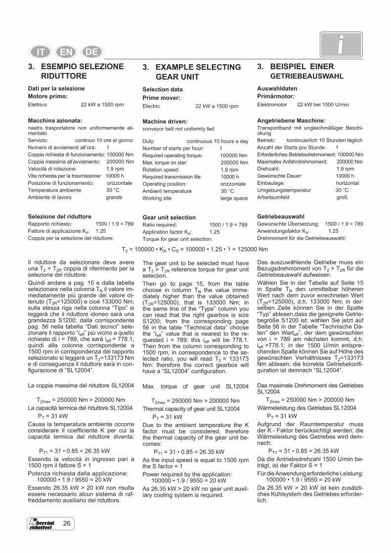
i3. EXAMPLE SELECTING GEAR UNIT Selection dataPrime mover: Electric 22 kW a 1500 rpm
Machine driven:conveyor belt not uniformly fed
Duty: continuous 10 hours a dayNumber of starts per hour: 1Required operating torque: 100000 NmMax. torque on star: 200000 NmRotation speed: 1.9 rpmRequired transmission life: 10000 hOperating position: orizzontaleAmbient temperature 30 °CWorking site large space
Gear unit selectionRatio required: 1500 / 1.9 = 789Application factor KA: 1.25Torque for gear unit selection:
The gear unit to be selected must have a T2 > T2R reference torque for gear unit selection.Then go to page 15, from the table choose in column TN the value imme-diately higher than the value obtained (T2R=125000), that is 133000 Nm; in the same line of the “Type” column you can read that the right gearbox is size S1200; from the corresponding page 56 in the table “Technical data” choose the “ieff” value that is nearest to the re-quested i = 789: this ieff will be 778.1. Then from the column corresponding to 1500 rpm, in correspondence to the se-lected ratio, you will read T2 = 133173 Nm: therefore the correct gearbox will have a “SL12004” configuration.
Max. torque of gear unit SL12004
T2max = 250000 Nm > 200000 NmThermal capacity of gear unit SL12004 PT = 31 kWDue to the ambient temperature the K factor must be considered, therefore the thermal capacity of the gear unit be-comes: PT1 = 31 • 0.85 = 26.35 kW As the input speed is equal to 1500 rpm the S factor = 1Power required by the application: 100000 • 1.9 / 9550 = 20 kWAs 26.35 kW > 20 kW no gear unit auxil-iary cooling system is required.
T2 = 100000 • KA • CS = 100000 • 1.25 • 1 = 125000 Nm
3. ESEMPIO SELEZIONE RIDUTTORE Dati per la selezioneMotore primo: Elettrico 22 kW a 1500 rpm
Macchina azionata:nastro trasportatore non uniformemente ali-mentatoServizio: continuo 10 ore al giornoNumero di avviamenti all’ora: 1Coppia richiesta di funzionamento: 100000 NmCoppia massima all’avviamento: 200000 NmVelocità di rotazione: 1.9 rpmVita richiesta per la trasmissione: 10000 hPosizione di funzionamento: orizzontaleTemperatura ambiente 30 °CAmbiente di lavoro grande
Selezione del riduttoreRapporto richiesto: 1500 / 1.9 = 789Fattore di applicazione KA: 1.25Coppia per la selezione del riduttore:
Il riduttore da selezionare deve avere una T2 > T2R coppia di riferimento per la selezione del riduttore.Quindi andare a pag. 15 e dalla tabella selezionare nella colonna TN il valore im-mediatamente più grande del valore ot-tenuto (T2R=125000) e cioè 133000 Nm; sulla stessa riga nella colonna “Tipo” si leggerà che il riduttore idoneo sarà una grandezza S1200; dalla corrispondente pag. 56 nella tabella “Dati tecnici” sele-zionare il rapporto “ieff” più vicino a quello richiesto di i = 789, che sarà ieff = 778.1, quindi alla colonna corrispondente a 1500 rpm in corrispondenza del rapporto selezionato si leggerà un T2=133173 Nm e di conseguenza il riduttore sarà in con-figurazione di “SL12004”.
La coppia massima del riduttore SL12004
T2max = 250000 Nm > 200000 NmLa capacità termica del riduttore SL12004 PT = 31 kWCausa la temperatura ambiente occorre considerare il coefficiente K per cui la capacità termica del riduttore diventa:
PT1 = 31 • 0.85 = 26.35 kW Essendo la velocità in ingresso pari a 1500 rpm il fattore S = 1Potenza richiesta dalla applicazione: 100000 • 1.9 / 9550 = 20 kWEssendo 26.35 kW > 20 kW non risulta essere necessario alcun sistema di raf-freddamento ausiliario del riduttore.
3. BEISPIEL EINER GETRIEBEAUSWAHL AuswahldatenPrimärmotor: Elektromotor 22 kW bei 1500 U/min
Angetriebene Maschine:Transportband mit ungleichmäßiger Beschi-ckungBetrieb: kontinuierlich 10 Stunden täglichAnzahl der Starts pro Stunde: 1Erforderliches Betriebsdrehmoment: 100000 NmMaximales Anfahrdrehmoment: 200000 NmDrehzahl: 1.9 rpmGewünschte Dauer: 10000 hEinbaulage: horizontalUmgebungstemperatur 30 °CArbeitsumfeld groß
GetriebeauswahlGewünschte Übersetzung: 1500 / 1.9 = 789Anwendungsfaktor KA: 1.25Drehmoment für die Getriebeauswahl:
Das auszuwählende Getriebe muss ein Bezugsdrehmoment von T2 > T2R für die Getriebeauswahl aufweisen.Wählen Sie in der Tabelle auf Seite 15 in Spalte TN den unmittelbar höheren Wert nach dem zuvor errechneten Wert (T2R=125000), d.h. 133000 Nm; in der-selben Zeile können Sie in der Spalte “Typ” ablesen,dass die geeignete Getrie-begröße S1200 ist; wählen Sie jetzt auf Seite 56 in der Tabelle “Technische Da-ten” den Werteff”, der dem gewünschten von i = 789 am nächsten kommt, d.h. ieff =778.1; in der 1500 U/min entspre-chenden Spalte können Sie auf Höhe des gewünschten Verhältnisses T2=133173 Nm ablesen; die korrekte Getriebekonfi-guration ist demnach “SL12004”.
Das maximale Drehmoment des Getriebes SL12004 T2max = 250000 Nm > 200000 NmWärmeleistung des Getriebes SL12004 PT = 31 kWAufgrund der Raumtemperatur muss der K - Faktor berücksichtigt werden; die Wärmeleistung des Getriebes wird dem-nach: PT1 = 31 • 0.85 = 26.35 kW Da die Antriebsdrehzahl 1500 U/min be-trägt, ist der Faktor S = 1Für die Anwendung erforderliche Leistung: 100000 • 1.9 / 9550 = 20 kWDa 26.35 kW > 20 kW ist kein zusätzli-ches Kühlsystem des Getriebes erforder-lich.

28
iApplicazioni che:● richiedono valori di durata diverse dalle
10000 ore● presentano velocità in entrata diverse
da quelle indicate a catalogo ● sono caratterizzate da cicli di lavoro
con carichi e velocità variabili● prevedono la presenza di carichi as-
siali sull’albero in ingresso / uscita del riduttore
devono essere analizzate specificata-mente. tramite l’ausilio di programmi di calcolo dedicati, disponibili presso l’organizzazione di vendita di Brevini Riduttori.
Applications that:● require duration values different from
10000 h● have different input speeds from those
given in the catalogue ● are characterized by work cycles with
variable speeds and loads● foresee the presence of axial loads on
the gear unit input / output shaft must be examined separately, with the aid of dedicated calculation pro-grams, available from the Brevini Riduttori sales organization.
Anwendungen mit:● von 10000 Betriebsstunden abwei-
chenden Werten● Antriebsdrehzahlen, die von den im
Katalog aufgeführten Werten abwei-chen
● regelbaren Arbeitszyklen und Dreh-zahlen
● Axiallasten auf der Antriebs-/Abtrieb-swelle des Getriebes
müssen separat mithilfe von spezifi-schen Rechenprogrammen analysiert werden, die von der Vertriebsorgani-sation Brevini Riduttori bezogen wer-den können.
31
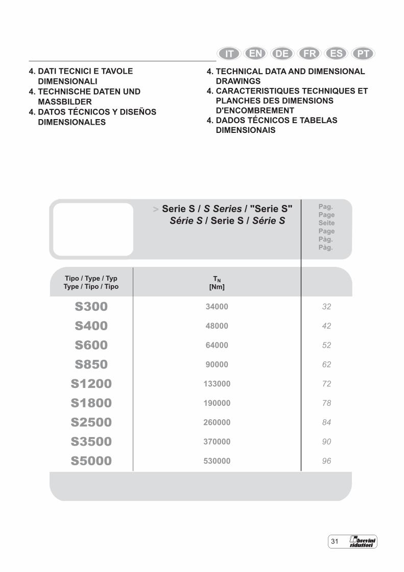
4. DATI TECNICI E TAVOLE DIMENSIONALI 4. TECHNISCHE DATEN UND MASSBILDER 4. DATOS TÉCNICOS Y DISEÑOS DIMENSIONALES
Serie S / S Series / "Serie S"
Série S / Serie S / Série S>
S300 34000 32
S400 48000 42
S600 64000 52
S850 90000 62
S1200 133000 72
S1800 190000 78
S2500 260000 84
S3500 370000 90
S5000 530000 96
Tipo / Type / Typ Type / Tipo / Tipo
TN [Nm]
Pag. Page Seite Page Pàg. Pàg.
4. TECHNICAL DATA AND DIMENSIONAL DRAWINGS4. CARACTERISTIQUES TECHNIQUES ET PLANCHES DES DIMENSIONS D'ENCOMBREMENT4. DADOS TÉCNICOS E TABELAS DIMENSIONAIS
32
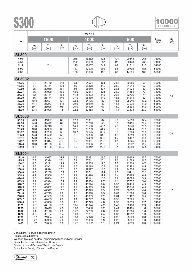
SL30014.04
*
248 16362 424 124 20143 261 760004.50 222 16609 387 111 20448 238 740005.12 195 17067 349 98 21011 215 590006.00 167 17528 306 83 20709 181 540007.36 136 13696 195 68 14291 102 36000
SL300215.96 94 21760 214 63 24574 161 31.3 30255 99 76000
38
17.86 84 22471 198 56 25378 149 28.0 31244 92 7600019.89 75 22969 181 50 25940 137 25.1 31224 82 7400022.77 66 23920 165 43.9 27014 124 22.0 31484 72 7400024.24 62 23751 154 41.3 26823 116 20.6 32776 71 7600027.00 56 25174 146 37.0 28430 110 18.5 31814 62 7400030.72 48.8 23601 121 32.6 24195 82 16.3 25246 43.0 5900033.75 44.4 25273 118 29.6 25910 80 14.8 27035 41.9 5850038.40 39.1 23926 98 26.0 24529 67 13.0 25594 34.9 5900045.00 33.3 21906 76 22.2 22458 52 11.1 23433 27.3 54000
SL300355.85 26.9 31687 89 17.9 33061 62 9.0 34559 32.4 76000
25
62.50 24.0 32472 82 16.0 33290 56 8.0 35151 29.4 7600071.55 21.0 32743 72 14.0 33568 49.1 7.0 35878 26.3 7600079.79 18.8 32963 65 12.5 33793 44.4 6.3 36474 23.9 7600093.57 16.0 33286 56 10.7 34125 38.2 5.3 37364 20.9 76000105.0 14.3 33522 50 9.5 34366 34.3 4.8 38019 19.0 76000107.1 14.0 33564 49.2 9.3 34409 33.6 4.7 38137 18.6 76000122.7 12.2 33844 43.3 8.2 35051 29.9 4.1 38925 16.6 76000145.4 10.3 34199 36.9 6.9 35966 25.9 3.4 39942 14.4 76000162.0 9.3 33196 32.2 6.2 34812 22.5 3.1 38660 12.5 74000
SL3004172.0 8.7 34697 31.7 5.8 36891 22.5 2.9 40969 12.5 76000
17
195.5 7.7 35374 28.4 5.1 37611 20.1 2.6 41769 11.2 76000230.7 6.5 36271 24.7 4.3 38565 17.5 2.2 42828 9.7 76000261.3 5.7 36961 22.2 3.8 39299 15.7 1.9 42181 8.5 76000288.8 5.2 37524 20.4 3.5 39897 14.5 1.7 44308 8.0 76000330.0 4.5 38289 18.2 3.0 40711 12.9 1.5 45211 7.2 76000369.9 4.1 38956 16.5 2.7 41420 11.7 1.4 45999 6.5 76000414.6 3.6 39634 15.0 2.4 42141 10.6 1.2 46799 5.9 76000463.9 3.2 40314 13.7 2.2 42864 9.7 1.1 47602 5.4 76000518.7 2.9 41001 12.4 1.9 43594 8.8 0.96 48413 4.9 76000578.5 2.6 41682 11.3 1.7 44319 8.0 0.86 49218 4.5 76000647.3 2.3 42397 10.3 1.5 45079 7.3 0.77 50062 4.0 76000741.0 2.0 43273 9.2 1.3 46010 6.5 0.67 51096 3.6 76000776.8 1.9 43583 8.8 1.3 46339 6.2 0.64 51462 3.5 76000889.2 1.7 44483 7.9 1.1 47297 5.6 0.56 52525 3.1 76000990.5 1.5 43056 6.8 1.0 45779 4.8 0.50 50839 2.7 740001175 1.3 44180 5.9 0.85 46974 4.2 0.43 52166 2.3 740001205 1.2 34413 4.5 0.83 36438 3.2 0.41 40465 1.8 590001392 1.1 35170 4.0 0.72 37239 2.8 0.36 41356 1.6 590001670 0.9 36154 3.4 0.60 38281 2.4 0.30 42512 1.3 590001733 0.87 21604 2.0 0.58 22970 1.4 0.29 25509 0.8 360001958 0.77 32996 2.6 0.51 35083 1.9 0.26 38961 1.0 540002401 0.62 22696 1.5 0.42 24132 1.1 0.21 26799 0.6 36000
ieff
n1 [rpm]
T2MAX [Nm]
PT [kW]
1500 1000 500n2
[rpm]T2
[Nm]P2
[kW]n2
[rpm]T2
[Nm]P2
[kW]n2
[rpm]T2
[Nm]P2
[kW]
(*)Consultare il Servizio Tecnico BreviniPlease consult BreviniWenden Sie sich an den Technischen Kundendienst BreviniConsulter le service technique BreviniContacte con el Servicio Técnico de BreviniConsultar o Serviço Técnico da Brevini
S300 10000HOURS LIFE
33
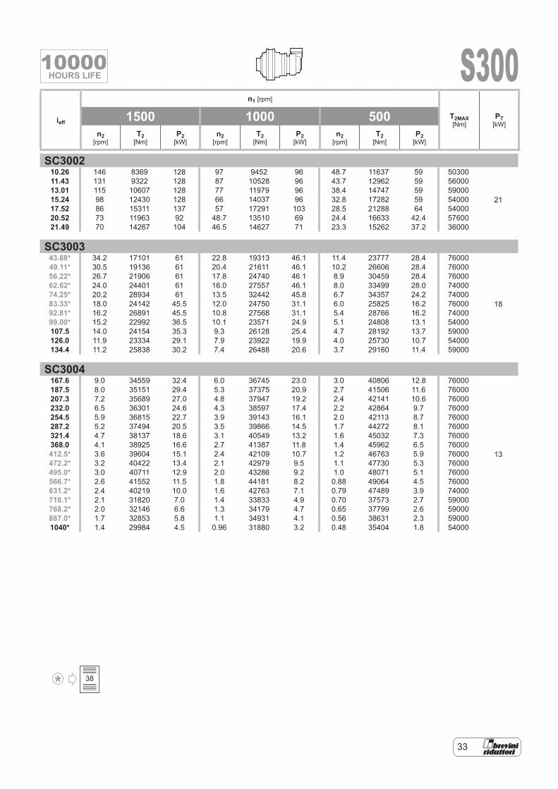
SC300210.26 146 8369 128 97 9452 96 48.7 11637 59 50300
21
11.43 131 9322 128 87 10528 96 43.7 12962 59 5600013.01 115 10607 128 77 11979 96 38.4 14747 59 5900015.24 98 12430 128 66 14037 96 32.8 17282 59 5400017.52 86 15311 137 57 17291 103 28.5 21288 64 5400020.52 73 11963 92 48.7 13510 69 24.4 16633 42.4 5760021.49 70 14267 104 46.5 14627 71 23.3 15262 37.2 36000
SC300343.88* 34.2 17101 61 22.8 19313 46.1 11.4 23777 28.4 76000
18
49.11* 30.5 19136 61 20.4 21611 46.1 10.2 26606 28.4 7600056.22* 26.7 21906 61 17.8 24740 46.1 8.9 30459 28.4 7600062.62* 24.0 24401 61 16.0 27557 46.1 8.0 33499 28.0 7400074.25* 20.2 28934 61 13.5 32442 45.8 6.7 34357 24.2 7400083.33* 18.0 24142 45.5 12.0 24750 31.1 6.0 25825 16.2 7600092.81* 16.2 26891 45.5 10.8 27568 31.1 5.4 28766 16.2 7400099.00* 15.2 22992 36.5 10.1 23571 24.9 5.1 24808 13.1 54000107.5 14.0 24154 35.3 9.3 26128 25.4 4.7 28192 13.7 59000126.0 11.9 23334 29.1 7.9 23922 19.9 4.0 25730 10.7 54000134.4 11.2 25838 30.2 7.4 26488 20.6 3.7 29160 11.4 59000
SC3004167.6 9.0 34559 32.4 6.0 36745 23.0 3.0 40806 12.8 76000
13
187.5 8.0 35151 29.4 5.3 37375 20.9 2.7 41506 11.6 76000207.3 7.2 35689 27.0 4.8 37947 19.2 2.4 42141 10.6 76000232.0 6.5 36301 24.6 4.3 38597 17.4 2.2 42864 9.7 76000254.5 5.9 36815 22.7 3.9 39143 16.1 2.0 42113 8.7 76000287.2 5.2 37494 20.5 3.5 39866 14.5 1.7 44272 8.1 76000321.4 4.7 38137 18.6 3.1 40549 13.2 1.6 45032 7.3 76000368.0 4.1 38925 16.6 2.7 41387 11.8 1.4 45962 6.5 76000412.5* 3.6 39604 15.1 2.4 42109 10.7 1.2 46763 5.9 76000472.2* 3.2 40422 13.4 2.1 42979 9.5 1.1 47730 5.3 76000495.0* 3.0 40711 12.9 2.0 43286 9.2 1.0 48071 5.1 76000566.7* 2.6 41552 11.5 1.8 44181 8.2 0.88 49064 4.5 76000631.2* 2.4 40219 10.0 1.6 42763 7.1 0.79 47489 3.9 74000718.1* 2.1 31820 7.0 1.4 33833 4.9 0.70 37573 2.7 59000768.2* 2.0 32146 6.6 1.3 34179 4.7 0.65 37799 2.6 59000887.0* 1.7 32853 5.8 1.1 34931 4.1 0.56 38631 2.3 590001040* 1.4 29984 4.5 0.96 31880 3.2 0.48 35404 1.8 54000
ieff
n1 [rpm]
T2MAX [Nm]
PT [kW]
1500 1000 500n2
[rpm]T2
[Nm]P2
[kW]n2
[rpm]T2
[Nm]P2
[kW]n2
[rpm]T2
[Nm]P2
[kW]
S300
38
10000HOURS LIFE
34
00 00
00
00
65.105
00
65.10548.8245.70
S00
S00S00
IECmotor
FL620/635FL5”FL6”SU-SUFS-45/46
S-65S-90ISL150ISL300IS300
S-65S-90IS300
FL5”S-45/46
FL5”FL6”S-45/46S-65
FL5”FL6”S-65
FL620/635SU-SUF
FL620/635SU-SUF FL620/635
SU-SUF
FL620/635SU-SUF
48.82FL5”
48.8245.70FL5”
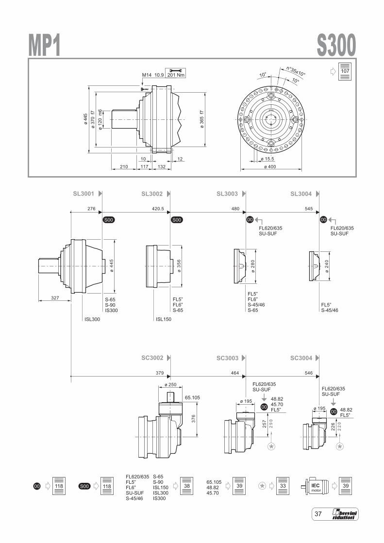
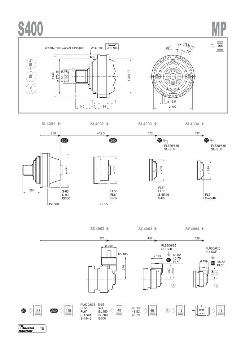
SL3001 SL3002 SL3003 SL3004
SC3002 SC3003 SC3004
ISL300 ISL150
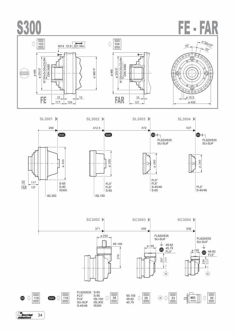
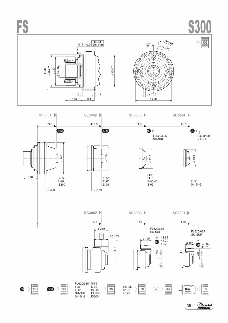
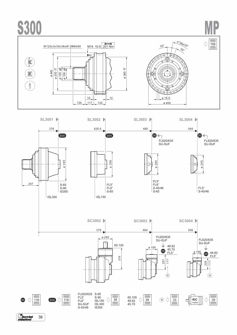
S300201 NmM14 10.9
10 12
117
117
124
ø 15.5
ø 400
ø44
5
ø44
5
ø37
0f7
ø37
0f7
ø36
5f7
DIN
5480
DIN
5480
268 412.5 472 537
371 456 538
ø 250
ø 195ø 195
ø44
5
ø35
6
ø28
0
ø24
0
376
257
29
0
226
22
0
10°10°
n°35x10°N
120x
5x30
x22x
9H
N12
0x5x
30x2
2x9H
10
137
FE - FAR
FE
FE
FAR
FAR 137
S300
118 118 38 39 33 39
103 104
35
118 118 38 39 33 39
105
36
118 118
106
38 39 33 39
37
107
118 118 38 39 33 39
38
00
00
SUS
FL62
0.U
SUF
IS
FL63
5.U
E
øD
k6S-45/46, S-65, S-90, ISL150, ISL300, IS300
SU-SUF
FL5”, FL6”
FL620/635
E
øD
m6
Lt
Lt
Lt
LtLt
S300
SAE A-AAShaft FE
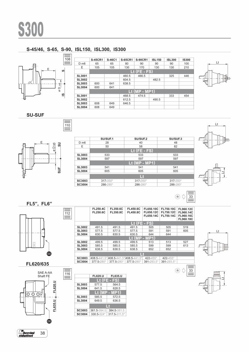
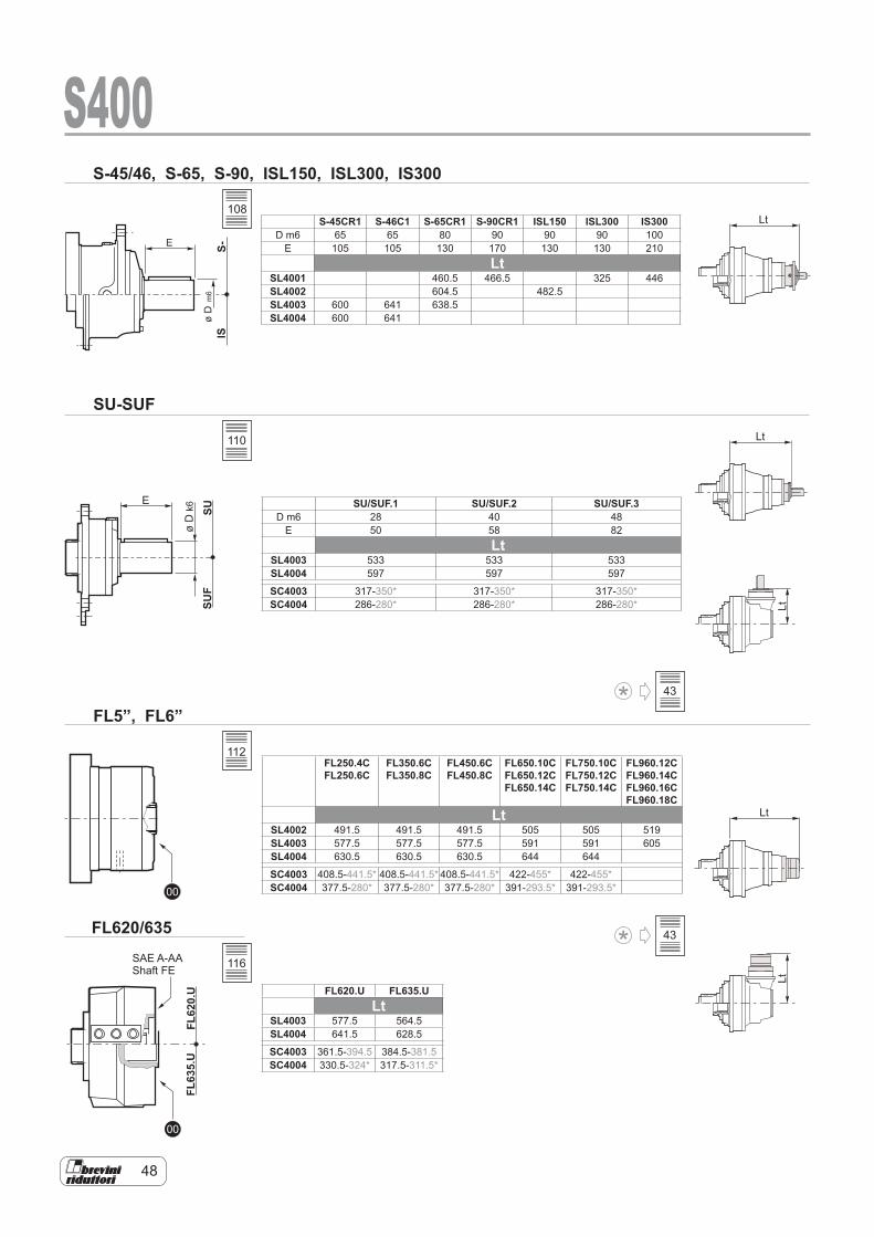
S-45CR1 S-46C1 S-65CR1 S-90CR1 ISL150 ISL300 IS300D m6 65 65 80 90 90 90 100
E 105 105 130 170 130 130 210Lt (FE - FS)
SL3001 460.5 466.5 325 446SL3002 604.5 482.5SL3003 600 641 638.5SL3004 600 641
Lt (MP - MP1)SL3001 468.5 474.5 333 454SL3002 612.5 490.5SL3003 608 649 646.5SL3004 608 649
SU/SUF.1 SU/SUF.2 SU/SUF.3D m6 28 40 48
E 50 58 82Lt (FE - FS)
SL3003 533 533 533SL3004 597 597 597
Lt (MP - MP1)SL3003 541 541 541SL3004 605 605 605
LtSC3003 317-350* 317-350* 317-350*SC3004 286-280* 286-280* 286-280*
FL250.4CFL250.6C
FL350.6C FL350.8C
FL450.6C FL450.8C
FL650.10C FL650.12C FL650.14C
FL750.10C FL750.12C FL750.14C
FL960.12C FL960.14C FL960.16C FL960.18C
Lt (FE - FS)SL3002 491.5 491.5 491.5 505 505 519SL3003 577.5 577.5 577.5 591 591 605SL3004 630.5 630.5 630.5 644 644
Lt (MP - MP1)SL3002 499.5 499.5 499.5 513 513 527SL3003 585.5 585.5 585.5 599 599 613SL3004 638.5 638.5 638.5 652 652
LtSC3003 408.5-441.5* 408.5-441.5* 408.5-441.5* 422-455* 422-455*SC3004 377.5-280* 377.5-280* 377.5-280* 391-293.5* 391-293.5*
FL620.U FL635.ULt (FE - FS)
SL3003 577.5 564.5SL3004 641.5 628.5
Lt (MP - MP1)SL3003 585.5 572.5SL3004 649.5 636.5
LtSC3003 361.5-394.5 384.5-381.5SC3004 330.5-324* 317.5-311.5*
108
110
112
116
33
33
39
IECmotor
hydraulic motor
E
øD
k6
t
b
d2
Lt
LtLt
S30065.105, 48.82, 45.70
PAM IEC
SAE J 744C, NEMA Adaptors
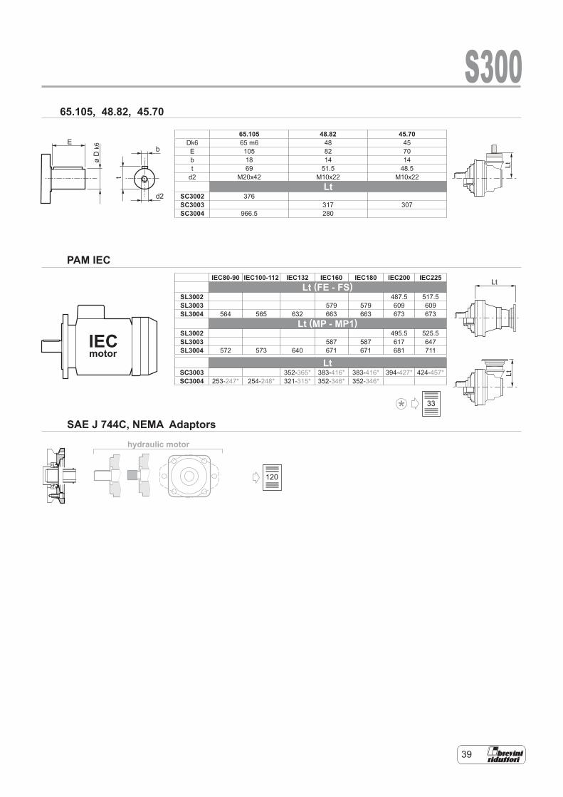
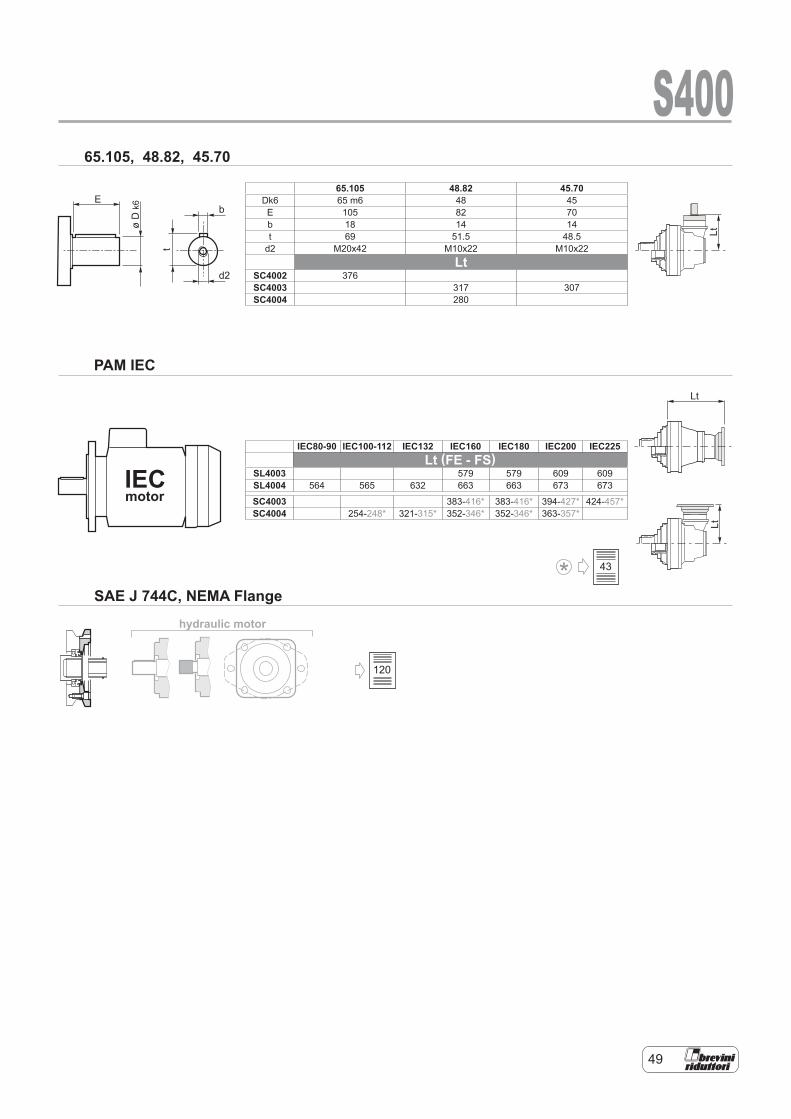
65.105 48.82 45.70Dk6 65 m6 48 45E 105 82 70b 18 14 14t 69 51.5 48.5
d2 M20x42 M10x22 M10x22Lt
SC3002 376SC3003 317 307SC3004 966.5 280
IEC80-90 IEC100-112 IEC132 IEC160 IEC180 IEC200 IEC225Lt (FE - FS)
SL3002 487.5 517.5SL3003 579 579 609 609SL3004 564 565 632 663 663 673 673
Lt (MP - MP1)SL3002 495.5 525.5SL3003 587 587 617 647SL3004 572 573 640 671 671 681 711
LtSC3003 352-365* 383-416* 383-416* 394-427* 424-457*SC3004 253-247* 254-248* 321-315* 352-346* 352-346*
120
33
40
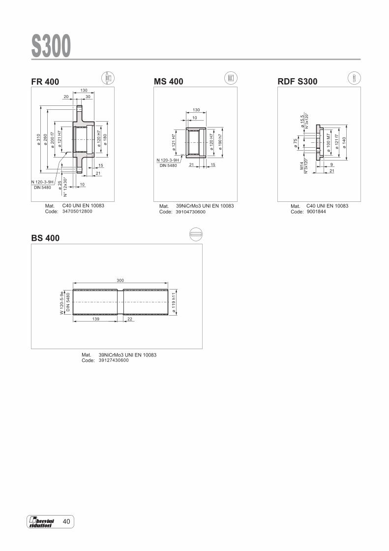
BS 400
RDF S300MS 400FR 400
Mat.Code:
Mat.Code:
Mat.Code:
Mat.Code:
ø31
0
ø26
0
ø20
0f7
ø18
0
10
30130
21
15
20
ø25
N°12
x30°N 120-3-9H
DIN 5480
34705012800
10
130
N 120-3-9HDIN 5480
ø14
0
ø10
0M7
ø11
9h1
1
139 22
300
W12
0-5-9e
DIN
5480
39127430600
ø75
ø15.5
N°3x120°
9001844
1521
ø121H7
ø121H7
ø121f7
ø120H7
ø120H7
ø190h7
M14
N°3x120°
S300
C40 UNI EN 10083 C40 UNI EN 1008339NiCrMo3 UNI EN 10083
39NiCrMo3 UNI EN 10083
39104730600
921
41
n ·h
10
10
2
6
5
86
4
2
0.80.6
0.4
0.2
0.20.1 0.3 0.4 0.5 0.7 1 1.5
S300
400000
350000
300000
250000
200000
150000
100000
50000
0-200 -150 -100 -50 0 50 100 150
mm
1 2 3
E
0
1 2 3
E
C
MP - MP1
FR [N]
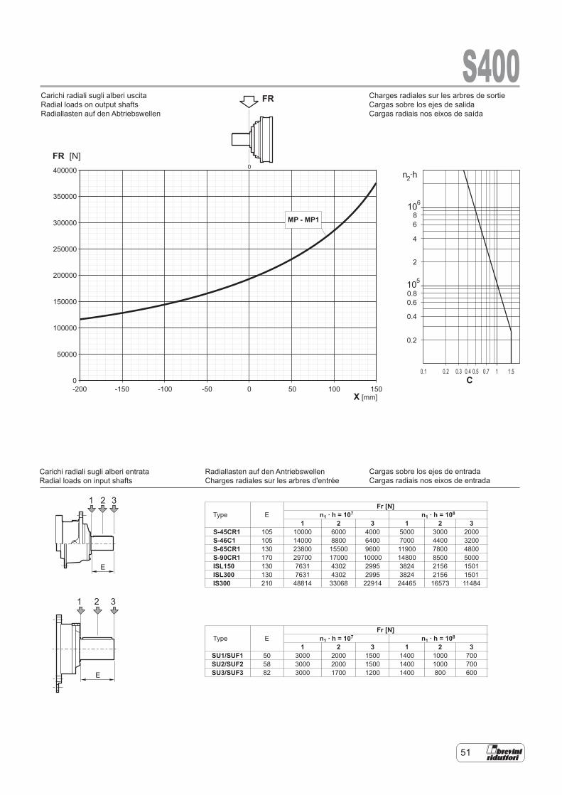
FRCarichi radiali sugli alberi uscita
Carichi radiali sugli alberi entrata
Radial loads on output shafts
Radial loads on input shafts
Type EFr [N]
n1 . h = 107 n1 . h = 108
1 2 3 1 2 3S-45CR1 105 10000 6000 4000 5000 3000 2000S-46C1 105 14000 8800 6400 7000 4400 3200S-65CR1 130 23800 15500 9600 11900 7800 4800S-90CR1 170 29700 17000 10000 14800 8500 5000ISL150 130 7631 4302 2995 3824 2156 1501ISL300 130 7631 4302 2995 3824 2156 1501IS300 210 48814 33068 22914 24465 16573 11484
Type EFr [N]
n1 . h = 107 n1 . h = 108
1 2 3 1 2 3SU1/SUF1 50 3000 2000 1500 1400 1000 700SU2/SUF2 58 3000 2000 1500 1400 1000 700SU3/SUF3 82 3000 1700 1200 1400 800 600
Charges radiales sur les arbres de sortie Cargas sobre los ejes de salida Cargas radiais nos eixos de saída
Cargas sobre los ejes de entrada Cargas radiais nos eixos de entrada
Radiallasten auf den Antriebswellen Charges radiales sur les arbres d'entrée
Carichi radiali sugli alberi uscita Radial loads on output shafts Radiallasten auf den Abtriebswellen
Carichi radiali sugli alberi entrata Radial loads on input shafts
42
S400
SL40014.18
*239 21853 547 120 26904 337 84000
4.89 204 22482 481 102 27679 296 840006.00 167 23371 408 83 27275 238 72000
SL400216.51 91 22514 214 61 25426 161 30.3 31303 99 84000
38
18.48 81 23250 198 54 26257 149 27.1 32327 92 8400019.32 78 26338 214 52 29745 161 25.9 36620 99 8400021.61 69 27199 198 46.3 30717 149 23.1 37779 92 8400024.74 61 27621 175 40.4 31194 132 20.2 38094 81 8400029.34 51 28748 154 34.1 32466 116 17.0 38494 69 8400030.36 49.4 28164 146 32.9 28873 100 16.5 30127 52 7200036.00 41.7 28460 124 27.8 29176 85 13.9 30444 44.3 7200045.00 33.3 28852 101 22.2 29579 69 11.1 30864 35.9 72000
SL400357.79 26.0 32785 89 17.3 37025 67 8.7 45584 41.3 84000
25
64.67 23.2 33856 82 15.5 38236 62 7.7 47074 38.1 8400067.60 22.2 37876 88 14.8 38830 60 7.4 40517 31.4 8400083.64 17.9 38374 72 12.0 39340 49.3 6.0 41049 25.7 8400093.59 16.0 38639 65 10.7 39613 44.3 5.3 41345 23.1 84000102.7 14.6 38860 59 9.7 39839 40.6 4.9 41930 21.4 84000110.9 13.5 39799 56 9.0 44946 42.5 4.5 51108 24.1 84000126.9 11.8 40416 50 7.9 45644 37.7 3.9 52164 21.5 84000146.7 10.2 39720 42.5 6.8 40720 29.1 3.4 44254 15.8 84000159.1 9.4 31176 30.8 6.3 31962 21.0 3.1 34209 11.3 72000
SL4004178.0 8.4 45945 40.5 5.6 49438 29.1 2.8 54903 16.2 84000
17
202.3 7.4 47741 37.1 4.9 50403 26.1 2.5 55975 14.5 84000226.3 6.6 48269 33.5 4.4 51268 23.7 2.2 56935 13.2 84000259.1 5.8 49214 29.8 3.9 52327 21.1 1.9 56892 11.5 84000288.9 5.2 50033 27.2 3.5 53197 19.3 1.7 59078 10.7 84000330.4 4.5 51058 24.3 3.0 54287 17.2 1.5 60288 9.6 84000370.1 4.1 51943 22.0 2.7 55228 15.6 1.4 59162 8.4 84000419.0 3.6 52925 19.8 2.4 56273 14.1 1.2 62493 7.8 84000468.8 3.2 53833 18.0 2.1 57238 12.8 1.1 63565 7.1 84000524.1 2.9 54748 16.4 1.9 56932 11.4 1.0 62358 6.2 84000580.0 2.6 55594 15.1 1.7 59110 10.7 0.86 65644 5.9 84000656.1 2.3 56304 13.5 1.5 58092 9.3 0.76 64513 5.1 84000718.2 2.1 57421 12.6 1.4 61053 8.9 0.70 67801 4.9 84000803.7 1.9 58406 11.4 1.2 62100 8.1 0.62 68964 4.5 84000920.1 1.6 57503 9.8 1.1 61140 7.0 0.54 67898 3.9 840001042 1.4 38498 5.8 1.0 40933 4.1 0.48 45288 2.3 720001076 1.4 50664 7.4 0.93 53869 5.2 0.46 59823 2.9 840001276 1.2 51987 6.4 0.78 55117 4.5 0.39 61209 2.5 840001413 1.1 40310 4.5 0.71 42700 3.2 0.35 47420 1.8 720001631 0.92 41197 4.0 0.61 43640 2.8 0.31 48464 1.6 720001958 0.77 42349 3.4 0.51 44860 2.4 0.26 49819 1.3 72000
ieff
n1 [rpm]
T2MAX [Nm]
PT [kW]
1500 1000 500n2
[rpm]T2
[Nm]P2
[kW]n2
[rpm]T2
[Nm]P2
[kW]n2
[rpm]T2
[Nm]P2
[kW]
(*)Consultare il Servizio Tecnico BreviniPlease consult BreviniWenden Sie sich an den Technischen Kundendienst BreviniConsulter le service technique BreviniContacte con el Servicio Técnico de BreviniConsultar o Serviço Técnico da Brevini
10000HOURS LIFE
43
S400
SC400212.21 123 10667 137 82 12046 103 41 14831 64 81893
21
14.28 105 12478 137 70 14092 103 35 17350 64 8400015.24 98 12430 128 66 14037 96 32.8 17282 59 7200017.52 86 15311 137 57 17291 103 28.5 21288 64 7200019.06 79 11112 92 52 12549 69 26.2 15450 42.4 5348322.30 67 12999 92 44.8 14681 69 22.4 18074 42.4 6256727.36 55 15950 92 36.5 18013 69 18.3 22177 42.4 72000
SC400345.41* 33.0 17693 61 22.0 19982 46.1 11 24601 28.4 84000
18
50.81* 29.5 19799 61 19.7 22360 46.1 9.8 27528 28.4 8400058.17* 25.8 22666 61 17.2 25597 46.1 8.6 31514 28.4 8400065.18* 23.0 25397 61 15.3 28682 46.1 7.7 31573 25.4 7200072.93* 20.6 28419 61 13.7 30468 43.7 6.9 31791 22.8 7200080.69* 18.6 31441 61 12.4 35508 46.1 6.2 40959 26.6 8400086.21* 17.4 24979 45.5 11.6 25608 31.1 5.8 26720 16.2 8400099.00* 15.2 30282 48.0 10.1 31044 32.8 5.1 32393 17.1 72000109.7 13.7 24649 35.3 9.1 25990 24.8 4.6 27119 12.9 84000123.8* 12.1 30699 39.0 8.1 31472 26.6 4.0 32933 13.9 72000142.9 10.5 23075 25.4 7.0 26060 19.1 3.5 32083 11.8 84000157.5 9.5 31157 31.1 6.3 31941 21.2 3.2 34156 11.4 72000
SC4004173.4 8.7 39100 35.4 5.8 44157 26.7 2.9 54364 16.4 84000
13
194.0 7.7 43752 35.4 5.2 49411 26.7 2.6 55623 15.0 84000214.5 7.0 48110 35.2 4.7 50853 24.8 2.3 56474 13.8 84000247.7 6.1 48880 31.0 4.0 51971 22.0 2.0 57716 12.2 84000277.1 5.4 49718 28.2 3.6 52863 20.0 1.8 58706 11.1 84000317.3 4.7 50745 25.1 3.2 53955 17.8 1.6 57799 9.5 84000371.2 4.0 43128 18.3 2.7 45856 12.9 1.3 50925 7.2 84000380.7 3.9 52164 21.5 2.6 55464 15.3 1.3 59415 8.2 84000457.7* 3.3 44795 15.4 2.2 50590 11.6 1.1 62283 7.1 84000512.1* 2.9 50126 15.4 2.0 56609 11.6 0.98 64420 6.6 84000586.3* 2.6 55685 14.9 1.7 57325 10.2 0.85 63425 5.7 84000599.1* 2.5 46368 12.2 1.7 49301 8.6 0.83 54750 4.8 84000685.9* 2.2 47326 10.8 1.5 50319 7.7 0.73 55882 4.3 84000813.3* 1.8 48562 9.4 1.2 51633 6.6 0.61 57176 3.7 84000900.2* 1.7 37654 6.6 1.1 40036 4.7 0.56 44296 2.6 720001040* 1.4 38483 5.8 0.96 40917 4.1 0.48 45271 2.3 720001247* 1.2 39559 5.0 0.80 42061 3.5 0.40 46536 2.0 72000
ieff
n1 [rpm]
T2MAX [Nm]
PT [kW]
1500 1000 500n2
[rpm]T2
[Nm]P2
[kW]n2
[rpm]T2
[Nm]P2
[kW]n2
[rpm]T2
[Nm]P2
[kW]
48
10000HOURS LIFE

44
00 00
00
65.105
00
S00S00
0065.10548.8245.70
S00 IECmotor
FL620/635FL5”FL6”SU-SUFS-45/46
S-65S-90ISL150ISL300IS300
S-65S-90IS300
FL5”S-45/46
FL5”FL6”S-45/46S-65
FL5”FL6”S-65
FL620/635SU-SUF
FL620/635SU-SUF FL620/635
SU-SUF
FL620/635SU-SUF
48.82FL5”
48.8245.70FL5
SL4001 SL4002 SL4003 SL4004
SC4002 SC4003 SC4004
201 NmM14 10.9
ISL300 ISL150
S400
10 12
140
140
124
ø 15.5
ø 400
ø44
5
ø37
0f7
ø36
5f7
DIN
5480
268 412.5 472 537
371 456 538
ø 250
ø 195ø 195
ø44
5
ø35
6
ø28
0
ø24
0
376
257
29
0
226
22
0
10°10°
n°35x10°N
140x
5x30
x26x
9H
N14
0x5x
30x2
6x9H
“
FE - FAR
FE FARø
445
ø37
0f7
DIN
5480
10
160
FEFAR 160
118 118
103
48 49 43 49
104

45
105
118 118 48 49 43 49
46
118 118
106
48 49 43 49

47
107
118 118 48 49 43 49
48
SUSU
F
E
øD
k6
00
00
FL62
0.U
FL63
5.U
S-IS
E
øD
m6
S-45/46, S-65, S-90, ISL150, ISL300, IS300
SU-SUF
FL5”, FL6”
FL620/635
Lt
Lt
Lt
LtLt
S400
SAE A-AAShaft FE
S-45CR1 S-46C1 S-65CR1 S-90CR1 ISL150 ISL300 IS300D m6 65 65 80 90 90 90 100
E 105 105 130 170 130 130 210Lt
SL4001 460.5 466.5 325 446SL4002 604.5 482.5SL4003 600 641 638.5SL4004 600 641
SU/SUF.1 SU/SUF.2 SU/SUF.3D m6 28 40 48
E 50 58 82Lt
SL4003 533 533 533SL4004 597 597 597
SC4003 317-350* 317-350* 317-350*SC4004 286-280* 286-280* 286-280*
FL250.4CFL250.6C
FL350.6C FL350.8C
FL450.6C FL450.8C
FL650.10C FL650.12C FL650.14C
FL750.10C FL750.12C FL750.14C
FL960.12C FL960.14C FL960.16C FL960.18C
LtSL4002 491.5 491.5 491.5 505 505 519SL4003 577.5 577.5 577.5 591 591 605SL4004 630.5 630.5 630.5 644 644
SC4003 408.5-441.5* 408.5-441.5* 408.5-441.5* 422-455* 422-455*SC4004 377.5-280* 377.5-280* 377.5-280* 391-293.5* 391-293.5*
FL620.U FL635.ULt
SL4003 577.5 564.5SL4004 641.5 628.5
SC4003 361.5-394.5 384.5-381.5SC4004 330.5-324* 317.5-311.5*
108
110
112
116
43
43
49
hydraulic motor
E
øD
k6
t
b
d2
IECmotor
Lt
LtLt
S40065.105, 48.82, 45.70
PAM IEC
SAE J 744C, NEMA Flange
65.105 48.82 45.70Dk6 65 m6 48 45E 105 82 70b 18 14 14t 69 51.5 48.5
d2 M20x42 M10x22 M10x22Lt
SC4002 376SC4003 317 307SC4004 280
IEC80-90 IEC100-112 IEC132 IEC160 IEC180 IEC200 IEC225Lt (FE - FS)
SL4003 579 579 609 609SL4004 564 565 632 663 663 673 673
SC4003 383-416* 383-416* 394-427* 424-457*SC4004 254-248* 321-315* 352-346* 352-346* 363-357*
120
43
50
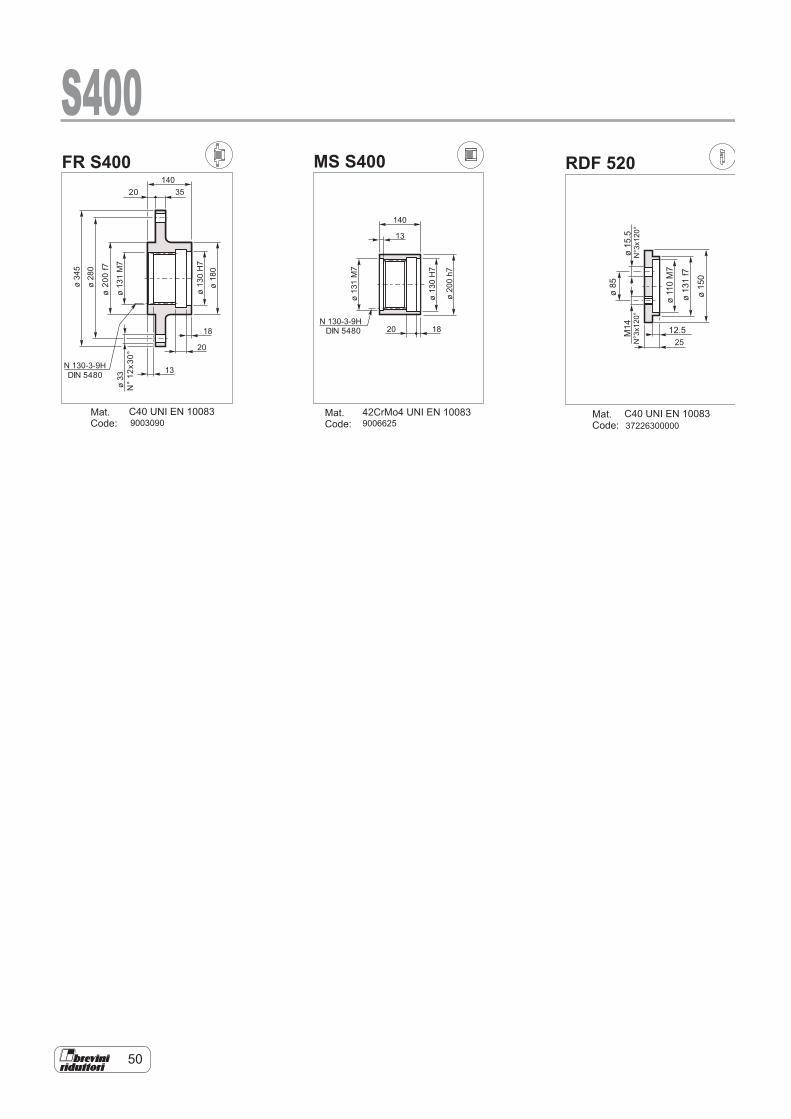
RDF 520MS S400FR S400
ø200f7
20
N°12x30°
DIN 5480
DIN 5480
ø85
ø150
ø15.5
N°3x120°
M14
N°3x120°
12.5
Mat.Code: 372263000009003090
Mat.Code:
Mat.Code:
C40 UNI EN 10083 C40 UNI EN 1008342CrMo4 UNI EN 10083
ø110M7
ø131f7
25
13
140
20 18
ø200h7
ø130H7
ø131M7
N 130-3-9H
N 130-3-9H
35140
20
18
13
ø33
ø130H7
ø180
ø131M7
ø280
ø345
S400
9006625
51
n ·h
10
10
2
6
5
86
4
2
0.80.6
0.4
0.2
0.20.1 0.3 0.4 0.5 0.7 1 1.5
S400
400000
350000
300000
250000
200000
150000
100000
50000
0-200 -150 -100 -50 0 50 100 150
FR [N]
FRCarichi radiali sugli alberi uscita
Carichi radiali sugli alberi entrata
Radial loads on output shafts
Radial loads on input shafts
X [mm]
1 2 3
E
0
1 2 3
E
C
MP - MP1
Type EFr [N]
n1 . h = 107 n1 . h = 108
1 2 3 1 2 3S-45CR1 105 10000 6000 4000 5000 3000 2000S-46C1 105 14000 8800 6400 7000 4400 3200S-65CR1 130 23800 15500 9600 11900 7800 4800S-90CR1 170 29700 17000 10000 14800 8500 5000ISL150 130 7631 4302 2995 3824 2156 1501ISL300 130 7631 4302 2995 3824 2156 1501IS300 210 48814 33068 22914 24465 16573 11484
Type EFr [N]
n1 . h = 107 n1 . h = 108
1 2 3 1 2 3SU1/SUF1 50 3000 2000 1500 1400 1000 700SU2/SUF2 58 3000 2000 1500 1400 1000 700SU3/SUF3 82 3000 1700 1200 1400 800 600
Charges radiales sur les arbres de sortie Cargas sobre los ejes de salida Cargas radiais nos eixos de saída
Cargas sobre los ejes de entrada Cargas radiais nos eixos de entrada
Radiallasten auf den Antriebswellen Charges radiales sur les arbres d'entrée
Carichi radiali sugli alberi entrata Radial loads on input shafts
Carichi radiali sugli alberi uscita Radial loads on output shafts Radiallasten auf den Abtriebswellen
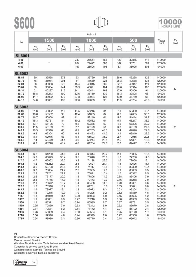
52
S600
SL60014.18
*239 26654 668 120 32815 411 140000
4.89 204 27422 587 102 33761 361 1200006.00 167 28506 498 83 35095 306 94000
SL600218.81 80 32558 272 53 36769 205 26.6 45268 126 140000
47
19.76 76 36914 294 51 41689 221 25.3 49588 131 12000022.01 68 38088 272 45.4 43015 205 22.7 49917 119 12000025.04 60 38864 244 39.9 43891 184 20.0 50314 105 12000029.34 51 40237 215 34.1 45441 162 17.0 50806 91 12000030.72 48.8 37213 190 32.6 38150 130 16.3 39808 68 9400035.99 41.7 38902 170 27.8 43934 128 13.9 46759 68 12000044.16 34.0 38051 135 22.6 39009 93 11.3 40704 48.3 94000
SL600368.90 21.8 48892 111 14.5 55216 84 7.3 63350 48.1 140000
31
80.60 18.6 50532 98 12.4 51805 67 6.2 54055 35.1 12000089.78 16.7 50868 89 11.1 52149 61 5.6 54414 31.7 12000098.12 15.3 52731 84 10.2 59552 64 5.1 66217 35.3 140000109.3 13.7 55196 79 9.2 62336 60 4.6 67306 32.2 140000130.2 11.5 58169 70 7.7 63129 51 3.8 69109 27.8 140000145.7 10.3 58310 63 6.9 60253 43.3 3.4 62870 22.6 140000163.6 9.2 62304 60 6.1 64423 41.2 3.1 69840 22.3 140000186.2 8.1 62946 53 5.4 65693 36.9 2.7 72955 20.5 140000203.0 7.4 53479 41.4 4.9 55244 28.5 2.5 61351 15.8 120000218.2 6.9 60246 43.4 4.6 61764 29.6 2.3 64447 15.5 140000
SL6004241.1 6.2 64250 41.9 4.1 68314 29.7 2.1 75865 16.5 140000
31
284.6 5.3 65879 36.4 3.5 70046 25.8 1.8 77788 14.3 140000317.0 4.7 66962 33.2 3.2 71198 23.5 1.6 79068 13.1 140000360.6 4.2 68282 29.7 2.8 72601 21.1 1.4 80626 11.7 140000413.4 3.6 69708 26.5 2.4 74117 18.8 1.2 82309 10.4 140000460.5 3.3 70854 24.2 2.2 75335 17.1 1.1 83663 9.5 140000523.9 2.9 72251 21.7 1.9 76821 15.4 1.0 85312 8.5 140000569.9 2.6 73177 20.2 1.8 77806 14.3 0.88 86406 7.9 140000655.7 2.3 74745 17.9 1.5 79473 12.7 0.76 88258 7.0 140000711.3 2.1 75672 16.7 1.4 80458 11.8 0.70 89351 6.6 140000792.3 1.9 76916 15.2 1.3 81781 10.8 0.63 90821 6.0 140000943.7 1.6 78977 13.1 1.1 83972 9.3 0.53 93254 5.2 140000962.6 1.6 79215 12.9 1.0 84225 9.2 0.52 87889 4.8 1400001117 1.3 81019 11.4 0.90 85003 8.0 0.45 88695 4.2 1400001307 1.1 68861 8.3 0.77 73216 5.9 0.38 81309 3.3 1200001350 1.1 83371 9.7 0.74 85995 6.7 0.37 89731 3.5 1400001579 0.95 70860 7.0 0.63 75342 5.0 0.32 83670 2.8 1200001851 0.81 72581 6.2 0.54 77172 4.4 0.27 85702 2.4 1200001986 0.76 56039 4.4 0.50 59584 3.1 0.25 66170 1.7 940002270 0.66 57916 4.0 0.44 61579 2.8 0.22 68386 1.6 1200002785 0.54 58980 3.3 0.36 62710 2.4 0.18 69642 1.3 94000
ieff
n1 [rpm]
T2MAX [Nm]
PT [kW]
1500 1000 500n2
[rpm]T2
[Nm]P2
[kW]n2
[rpm]T2
[Nm]P2
[kW]n2
[rpm]T2
[Nm]P2
[kW]
(*)Consultare il Servizio Tecnico BreviniPlease consult BreviniWenden Sie sich an den Technischen Kundendienst BreviniConsulter le service technique BreviniContacte con el Servicio Técnico de BreviniConsultar o Serviço Técnico da Brevini
10000HOURS LIFE
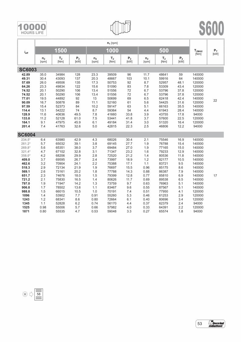
53
S600
SC600342.89 35.0 34984 128 23.3 39509 96 11.7 48641 59 140000
22
49.31 30.4 43093 137 20.3 48667 103 10.1 59916 64 14000057.69 26.0 49506 135 17.3 50753 92 8.7 52957 48.1 12000064.26 23.3 49834 122 15.6 51090 83 7.8 53309 43.4 12000074.52 20.1 50290 106 13.4 51556 72 6.7 53796 37.8 12000074.52 20.1 50290 106 13.4 51556 72 6.7 53796 37.8 12000077.01 19.5 44892 92 13 50699 69 6.5 62418 42.4 14000090.09 16.7 50878 89 11.1 52160 61 5.6 54425 31.6 12000097.59 15.4 52373 84 10.2 59147 63 5.1 66163 35.5 140000114.4 13.1 54222 74 8.7 59364 54 4.4 61943 28.4 140000128.9 11.6 40636 49.5 7.8 41660 33.8 3.9 43755 17.8 94000133.8 11.2 52128 61.0 7.5 53441 41.8 3.7 57600 22.5 120000164.1 9.1 47975 45.9 6.1 49184 31.4 3.0 51320 16.4 120000201.4 7.4 41763 32.6 5.0 42815 22.3 2.5 46806 12.2 94000
SC6004234.5* 6.4 63980 42.9 4.3 68026 30.4 2.1 75546 16.9 140000
17
261.2* 5.7 65032 39.1 3.8 69145 27.7 1.9 76788 15.4 140000269.8* 5.6 65351 38.0 3.7 69484 27.0 1.9 77165 15.0 140000321.4* 4.7 67102 32.8 3.1 71347 23.2 1.6 79233 12.9 140000358.0* 4.2 68206 29.9 2.8 72520 21.2 1.4 80536 11.8 140000409.0 3.7 69595 26.7 2.4 73997 18.9 1.2 82177 10.5 140000462.6 3.2 70904 24.1 2.2 75388 17.1 1.1 83721 9.5 140000518.3 2.9 72134 21.9 1.9 76697 15.5 0.96 85175 8.6 140000569.1 2.6 73161 20.2 1.8 77788 14.3 0.88 86387 7.9 140000651.7 2.3 74676 18.0 1.5 79399 12.8 0.77 85810 6.9 140000721.2 2.1 75830 16.5 1.4 80626 11.7 0.69 89538 6.5 140000797.0 1.9 71947 14.2 1.3 73759 9.7 0.63 76963 5.1 140000906.8 1.7 78502 13.6 1.1 83467 9.6 0.55 87567 5.1 140000988.8 1.5 66015 10.5 1.0 70191 7.4 0.51 77950 4.1 1200001096 1.4 53902 7.7 0.91 55260 5.3 0.46 61253 2.9 1200001243 1.2 68341 8.6 0.80 72664 6.1 0.40 80696 3.4 1200001345 1.1 52828 6.2 0.74 56170 4.4 0.37 62379 2.4 940001525 0.98 55006 5.7 0.66 57982 4.0 0.33 64391 2.2 1200001871 0.80 55535 4.7 0.53 59048 3.3 0.27 65574 1.8 94000
ieff
n1 [rpm]
T2MAX [Nm]
PT [kW]
1500 1000 500n2
[rpm]T2
[Nm]P2
[kW]n2
[rpm]T2
[Nm]P2
[kW]n2
[rpm]T2
[Nm]P2
[kW]
58
10000HOURS LIFE
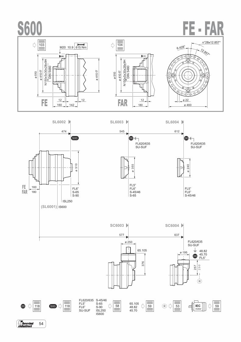
54
00 00
00
S00
0065.10548.8245.70
S00 IECmotor
FL620/635FL5”FL6”SU-SUF
S-45/46S-65S-90ISL250IS600
(SL6001)
SL6002 SL6003 SL6004
SC6003 SC6004
IS600
FL6”S-65S-90
FL5”FL6”S-45/46
FL5”FL6”S-45/46S-65
FL620/635SU-SUF
48.8245.70FL5”
FL620/635SU-SUF
FL620/635SU-SUF
65.105
ISL250
S600615 NmM20 10.9
12 1212
160
160
142
ø 22
ø 460
ø51
0
ø51
0
ø41
0f7
ø41
0f7
ø41
5f7
DIN
5480
474 545 612
577 637
ø51
0
ø35
5
ø24
0
N15
0x5x
30x2
8x9H
N15
0x5x
30x2
8x9H
ø 250
ø 195
257
29
0376
6.428°12.857°
n°28x12.857°
FE - FAR
FE FAR
DIN
5480
180
FEFAR 180
118 118
103
58 59 53 59
104
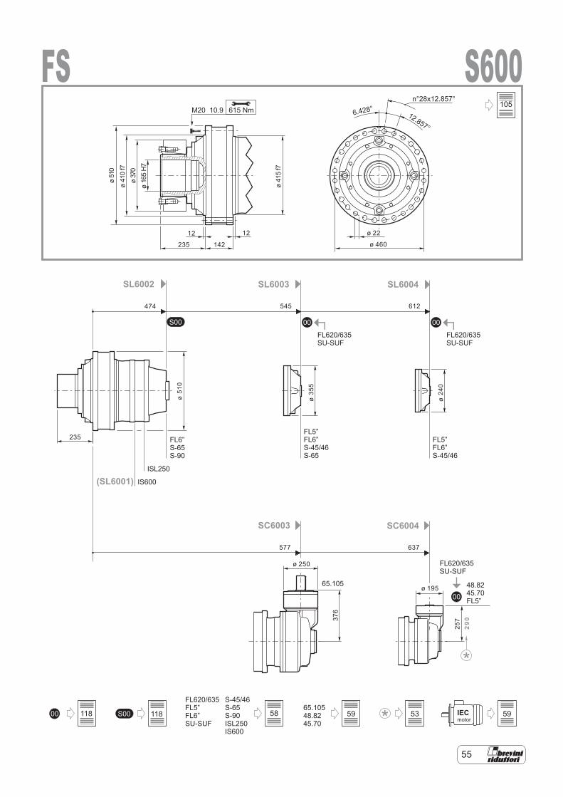
55
00 00
00
S00
0065.10548.8245.70
S00 IECmotor
FL620/635FL5”FL6”SU-SUF
S-45/46S-65S-90ISL250IS600
(SL6001)
SL6002 SL6003 SL6004
SC6003 SC6004
IS600
FL6”S-65S-90
FL5”FL6”S-45/46
FL5”FL6”S-45/46S-65
FL620/635SU-SUF
48.8245.70FL5”
FL620/635SU-SUF
FL620/635SU-SUF
65.105
ISL250
S600FS615 NmM20 10.9
474 545 612
577 637
ø51
0
ø35
5
ø24
0
12 12
235
235
142
ø 22
ø 460
ø51
0ø
410
f7ø
370
ø16
5H
7
ø41
5f7
ø 250
ø 195
257
29037
6
6.428°12.857°
n°28x12.857°105
118 118 58 59 53 59
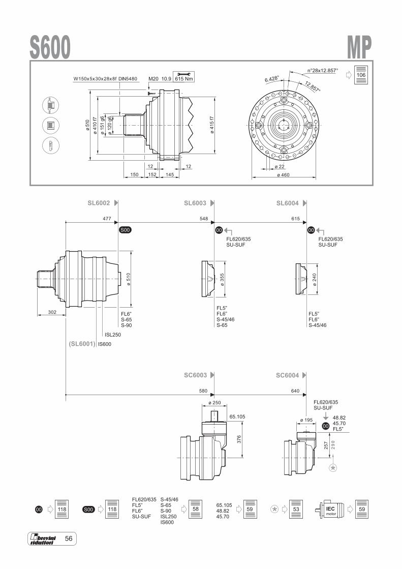
56
00 00
00
S00
FL620/635FL5”FL6”SU-SUF
0065.10548.8245.70
S-45/46S-65S-90ISL250IS600
S00 IECmotor
SL6002
(SL6001)
SL6003 SL6004
SC6003 SC6004
FL6”S-65S-90
IS600
FL5”
S-45/46FL6”
FL5”FL6”S-45/46S-65
FL620/635SU-SUF
48.8245.70FL5”
FL620/635SU-SUF
FL620/635SU-SUF
65.105
ISL250
S600 MP615 NmM20 10.9
12 12
150 152 145
ø 22
ø 460
302
ø 250
ø 195
ø51
0
ø35
5
ø24
0
257
290
ø51
0ø
410
f7
ø41
5f7
ø15
1g6
ø12
0g6
W150x5x30x28x8f DIN5480
376
6.428°12.857°
n°28x12.857°
477 548 615
580 640
118 118
106
58 59 53 59
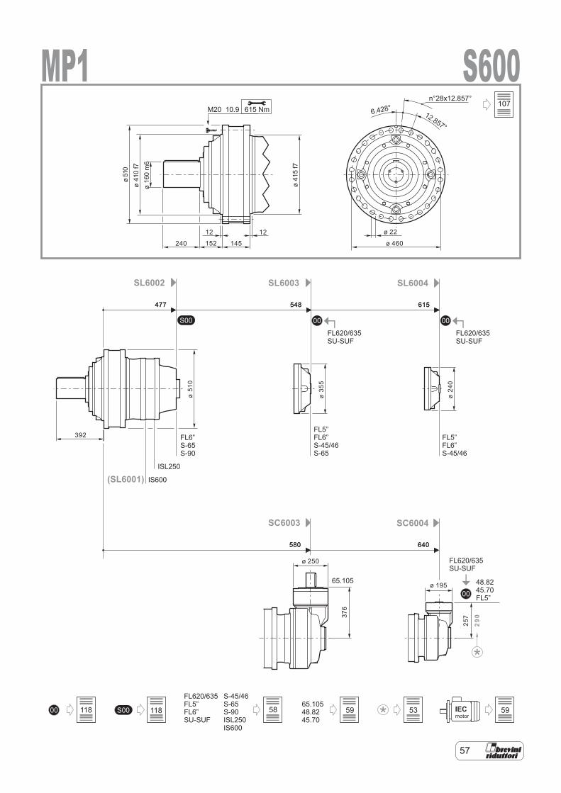
57
00 00
00
S00
0065.10548.8245.70
S00 IECmotor
FL620/635FL5”FL6”SU-SUF
S-45/46S-65S-90ISL250IS600
(SL6001)
SL6002 SL6003 SL6004
SC6003 SC6004
IS600
FL6”S-65S-90
FL5”FL6”S-45/46
FL5”FL6”S-45/46S-65
FL620/635SU-SUF
48.8245.70FL5”
FL620/635SU-SUF
FL620/635SU-SUF
65.105
ISL250
S600MP1615 NmM20 10.9
ø51
0
ø35
5
ø24
0
12 12
240 152 145
ø 22
ø 460
ø51
0ø
410
f7
ø41
5f7
392
ø16
0m
6
ø 250
ø 195
257
29037
6
6.428°12.857°
n°28x12.857°
477 548 615
580 640
477 548 615
580 640
107
118 118 58 59 53 59
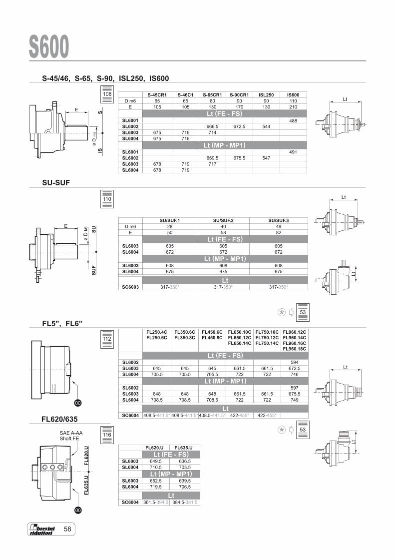
58
USF
US
E
Dø
k6
00
00
U.026LFU.536LF
SAE A-AAShaft FE
S-45/46, S-65, S-90, ISL250, IS600
SU-SUF
FL5”, FL6”
FL620/635
Lt
Lt
Lt
tLtL
S600S
SI
E
Dø
6m
S-45CR1 S-46C1 S-65CR1 S-90CR1 ISL250 IS600D m6 65 65 80 90 90 110
E 105 105 130 170 130 210Lt (FE - FS)
SL6001SL6002 666.5 672.5 544
488
SL6003 675 716 714SL6004 675 716
Lt (MP - MP1)SL6001 491SL6002 669.5 675.5 547SL6003 678 719 717SL6004 678 719
SU/SUF.1 SU/SUF.2 SU/SUF.3D m6 28 40 48
E 50 58 82Lt (FE - FS)
SL6003 605 605 605SL6004 672 672 672
Lt (MP - MP1)SL6003 608 608 608SL6004 675 675 675
LtSC6003 317-350* 317-350* 317-350*
FL250.4CFL250.6C
FL350.6C FL350.8C
FL450.6C FL450.8C
FL650.10C FL650.12C FL650.14C
FL750.10C FL750.12C FL750.14C
FL960.12C FL960.14C FL960.16C FL960.18C
Lt (FE - FS)SL6002 594SL6003 645 645 645 661.5 661.5 672.5SL6004 705.5 705.5 705.5 722 722 746
Lt (MP - MP1)SL6002 597SL6003 648 648 648 661.5 661.5 675.5SL6004 708.5 708.5 708.5 722 722 749
LtSC6004 408.5-441.5* 408.5-441.5* 408.5-441.5* 422-455* 422-455*
FL620.U FL635.ULt (FE - FS)
SL6003 649.5 636.5SL6004 710.5 703.5
Lt (MP - MP1)SL6003 652.5 639.5SL6004 719.5 706.5
LtSC6004 361.5-394.5 384.5-381.5
108
110
112
116
53
53
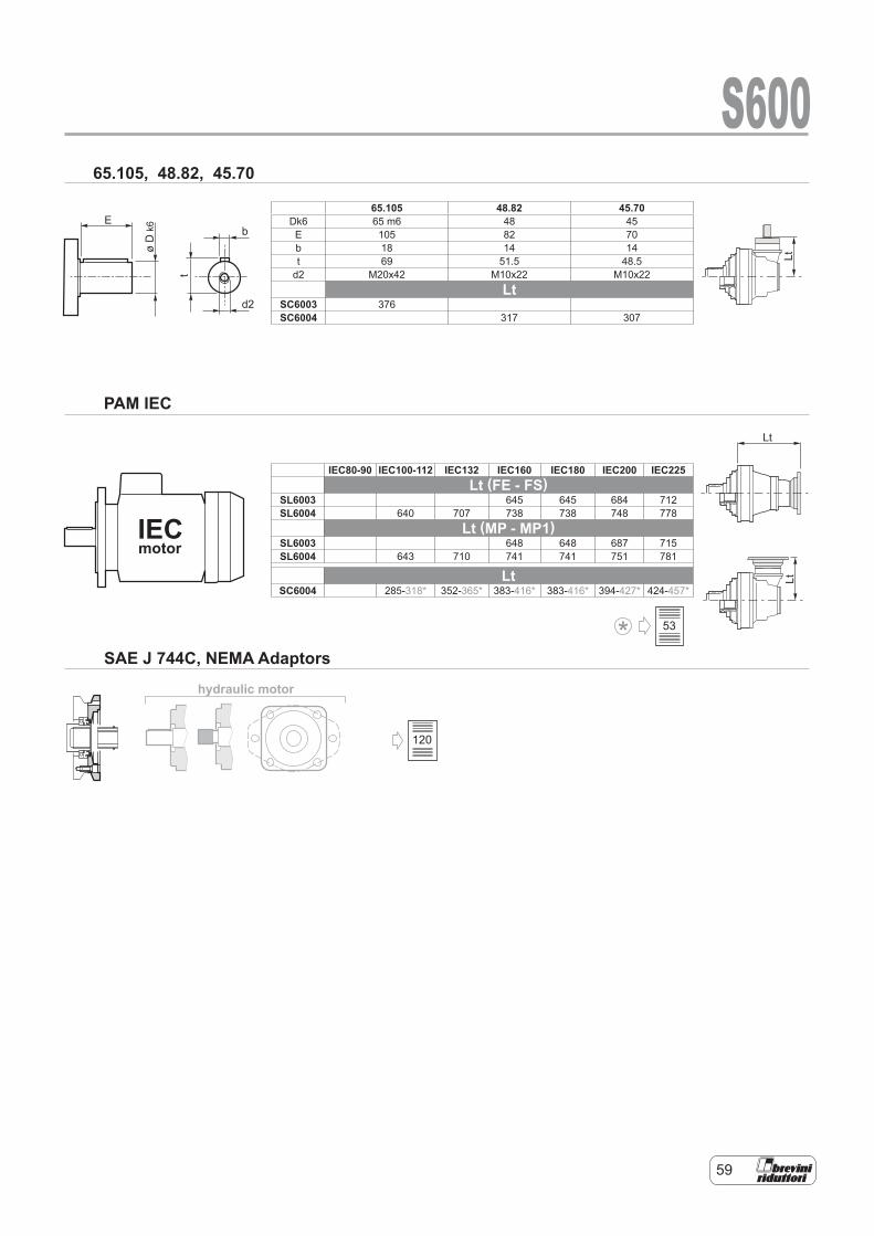
59
hydraulic motor
E
øD
k6
t
b
d2
IECmotor
Lt
LtLt
S60065.105, 48.82, 45.70
PAM IEC
SAE J 744C, NEMA Adaptors
65.105 48.82 45.70Dk6 65 m6 48 45E 105 82 70b 18 14 14t 69 51.5 48.5
d2 M20x42 M10x22 M10x22Lt
SC6003 376SC6004 317 307
IEC80-90 IEC100-112 IEC132 IEC160 IEC180 IEC200 IEC225Lt (FE - FS)
SL6003 645 645 684 712SL6004 640 707 738 738 748 778
Lt (MP - MP1)SL6003 648 648 687 715SL6004 643 710 741 741 751 781
LtSC6004 285-318* 352-365* 383-416* 383-416* 394-427* 424-457*
120
53

60
RDF S600MS 600FR 600
ø38
5
ø32
0
ø22
0f7
ø22
0
12
40150
27
18
25
ø32
N°
12x3
0°N 150-5-9HDIN 5480
12
150
N 150-5-9HDIN 5480
ø17
0
ø12
0M
7
1125
Mat.Code:
Mat.Code:
Mat.Code:
ø95
C45 UNI EN 10083 C40 UNI EN 1008342CrMo4 UNI EN 10083
ø15
.5N
°3x1
20°
39111330600 900184534704012800
ø15
1H
7
ø15
1H
7
ø15
1H
7
ø15
1H
7
ø15
1f7
ø22
0h7
1827
M14
N°3
x120
°
S600
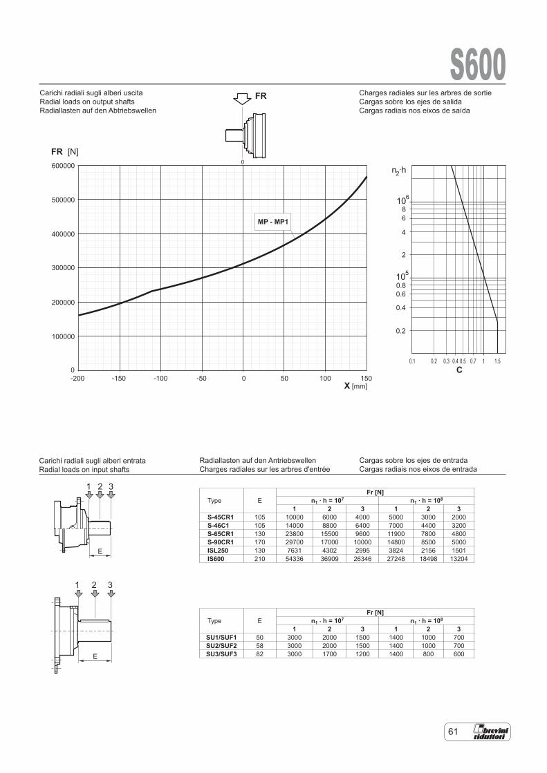
61
Type EFr [N]
n1 . h = 107 n1 . h = 108
1 2 3 1 2 3S-45CR1 105 10000 6000 4000 5000 3000 2000S-46C1 105 14000 8800 6400 7000 4400 3200S-65CR1 130 23800 15500 9600 11900 7800 4800S-90CR1 170 29700 17000 10000 14800 8500 5000ISL250 130 7631 4302 2995 3824 2156 1501IS600 210 54336 36909 26346 27248 18498 13204
Type EFr [N]
n1 . h = 107 n1 . h = 108
1 2 3 1 2 3SU1/SUF1 50 3000 2000 1500 1400 1000 700SU2/SUF2 58 3000 2000 1500 1400 1000 700SU3/SUF3 82 3000 1700 1200 1400 800 600
Charges radiales sur les arbres de sortie Cargas sobre los ejes de salida Cargas radiais nos eixos de saída
Cargas sobre los ejes de entrada Cargas radiais nos eixos de entrada
Radiallasten auf den Antriebswellen Charges radiales sur les arbres d'entrée
n ·h
10
10
2
6
5
86
4
2
0.80.6
0.4
0.2
0.20.1 0.3 0.4 0.5 0.7 1 1.5
S600
600000
500000
400000
300000
200000
100000
0-200 -150 -100 -50 0 50 100 150
FR [N]
FRCarichi radiali sugli alberi uscita
Carichi radiali sugli alberi entrata
Radial loads on output shafts
Radial loads on input shafts
X [mm]
1 2 3
E
0
1 2 3
E
MP - MP1
C
Carichi radiali sugli alberi entrata Radial loads on input shafts
Carichi radiali sugli alberi uscita Radial loads on output shafts Radiallasten auf den Abtriebswellen
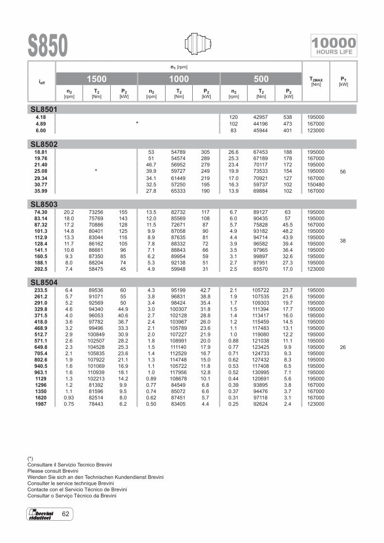
62
S850
SL85014.18
*120 42957 538 195000
4.89 102 44196 473 1670006.00 83 45944 401 123000
SL850218.81 53 54789 305 26.6 67453 188 195000
56
19.76 51 54574 289 25.3 67189 178 16700021.40 46.7 56952 279 23.4 70117 172 19500025.08 * 39.9 59727 249 19.9 73533 154 19500029.34 34.1 61449 219 17.0 70921 127 16700030.77 32.5 57250 195 16.3 59737 102 15048035.99 27.8 65333 190 13.9 69884 102 167000
SL850374.30 20.2 73256 155 13.5 82732 117 6.7 89127 63 195000
38
83.14 18.0 75769 143 12.0 85569 108 6.0 90435 57 19500087.32 17.2 70886 128 11.5 72671 87 5.7 75828 45.5 167000101.3 14.8 80401 125 9.9 87058 90 4.9 93182 48.2 195000112.9 13.3 83044 116 8.9 87635 81 4.4 94714 43.9 195000128.4 11.7 86162 105 7.8 88332 72 3.9 96582 39.4 195000141.1 10.6 86661 96 7.1 88843 66 3.5 97965 36.4 195000160.5 9.3 87350 85 6.2 89954 59 3.1 99897 32.6 195000188.1 8.0 88204 74 5.3 92138 51 2.7 97951 27.3 195000202.5 7.4 58475 45 4.9 59948 31 2.5 65570 17.0 123000
SL8504233.5 6.4 89536 60 4.3 95199 42.7 2.1 105722 23.7 195000
26
261.2 5.7 91071 55 3.8 96831 38.8 1.9 107535 21.6 195000291.0 5.2 92569 50 3.4 98424 35.4 1.7 109303 19.7 195000329.8 4.6 94340 44.9 3.0 100307 31.8 1.5 111394 17.7 195000371.5 4.0 96053 40.6 2.7 102128 28.8 1.4 113417 16.0 195000418.0 3.6 97782 36.7 2.4 103967 26.0 1.2 115459 14.5 195000468.9 3.2 99496 33.3 2.1 105789 23.6 1.1 117483 13.1 195000512.7 2.9 100849 30.9 2.0 107227 21.9 1.0 119080 12.2 195000571.1 2.6 102507 28.2 1.8 108991 20.0 0.88 121038 11.1 195000649.8 2.3 104528 25.3 1.5 111140 17.9 0.77 123425 9.9 195000705.4 2.1 105835 23.6 1.4 112529 16.7 0.71 124733 9.3 195000802.6 1.9 107922 21.1 1.3 114748 15.0 0.62 127432 8.3 195000940.5 1.6 101069 16.9 1.1 105722 11.8 0.53 117408 6.5 195000963.1 1.6 110939 18.1 1.0 117956 12.8 0.52 130995 7.1 1950001129 1.3 102213 14.2 0.89 108678 10.1 0.44 120691 5.6 1950001296 1.2 81392 9.9 0.77 84549 6.8 0.39 93895 3.8 1670001350 1.1 81596 9.5 0.74 85072 6.6 0.37 94476 3.7 1670001620 0.93 82514 8.0 0.62 87451 5.7 0.31 97118 3.1 1670001987 0.75 78443 6.2 0.50 83405 4.4 0.25 92624 2.4 123000
ieff
n1 [rpm]
T2MAX [Nm]
PT [kW]
1500 1000 500n2
[rpm]T2
[Nm]P2
[kW]n2
[rpm]T2
[Nm]P2
[kW]n2
[rpm]T2
[Nm]P2
[kW]
(*)Consultare il Servizio Tecnico BreviniPlease consult BreviniWenden Sie sich an den Technischen Kundendienst BreviniConsulter le service technique BreviniContacte con el Servicio Técnico de BreviniConsultar o Serviço Técnico da Brevini
10000HOURS LIFE
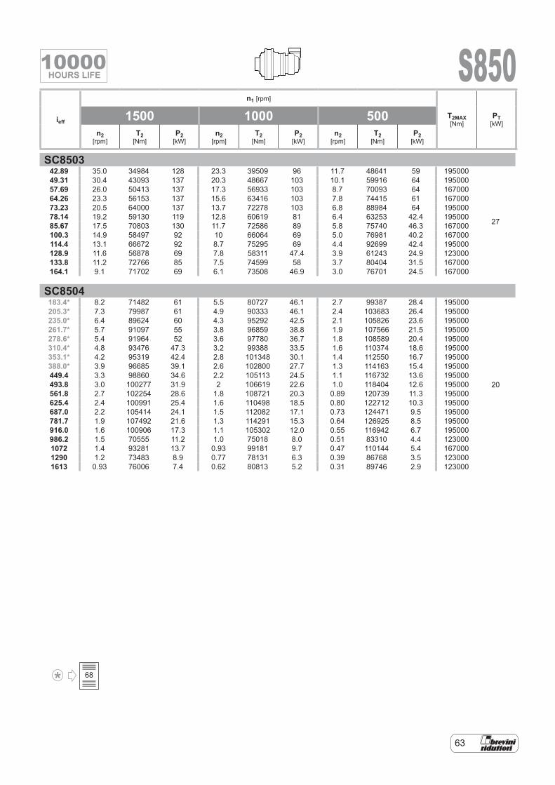
63
S850
SC850342.89 35.0 34984 128 23.3 39509 96 11.7 48641 59 195000
27
49.31 30.4 43093 137 20.3 48667 103 10.1 59916 64 19500057.69 26.0 50413 137 17.3 56933 103 8.7 70093 64 16700064.26 23.3 56153 137 15.6 63416 103 7.8 74415 61 16700073.23 20.5 64000 137 13.7 72278 103 6.8 88984 64 19500078.14 19.2 59130 119 12.8 60619 81 6.4 63253 42.4 19500085.67 17.5 70803 130 11.7 72586 89 5.8 75740 46.3 167000100.3 14.9 58497 92 10 66064 69 5.0 76981 40.2 167000114.4 13.1 66672 92 8.7 75295 69 4.4 92699 42.4 195000128.9 11.6 56878 69 7.8 58311 47.4 3.9 61243 24.9 123000133.8 11.2 72766 85 7.5 74599 58 3.7 80404 31.5 167000164.1 9.1 71702 69 6.1 73508 46.9 3.0 76701 24.5 167000
SC8504183.4* 8.2 71482 61 5.5 80727 46.1 2.7 99387 28.4 195000
20
205.3* 7.3 79987 61 4.9 90333 46.1 2.4 103683 26.4 195000235.0* 6.4 89624 60 4.3 95292 42.5 2.1 105826 23.6 195000261.7* 5.7 91097 55 3.8 96859 38.8 1.9 107566 21.5 195000278.6* 5.4 91964 52 3.6 97780 36.7 1.8 108589 20.4 195000310.4* 4.8 93476 47.3 3.2 99388 33.5 1.6 110374 18.6 195000353.1* 4.2 95319 42.4 2.8 101348 30.1 1.4 112550 16.7 195000388.0* 3.9 96685 39.1 2.6 102800 27.7 1.3 114163 15.4 195000449.4 3.3 98860 34.6 2.2 105113 24.5 1.1 116732 13.6 195000493.8 3.0 100277 31.9 2 106619 22.6 1.0 118404 12.6 195000561.8 2.7 102254 28.6 1.8 108721 20.3 0.89 120739 11.3 195000625.4 2.4 100991 25.4 1.6 110498 18.5 0.80 122712 10.3 195000687.0 2.2 105414 24.1 1.5 112082 17.1 0.73 124471 9.5 195000781.7 1.9 107492 21.6 1.3 114291 15.3 0.64 126925 8.5 195000916.0 1.6 100906 17.3 1.1 105302 12.0 0.55 116942 6.7 195000986.2 1.5 70555 11.2 1.0 75018 8.0 0.51 83310 4.4 1230001072 1.4 93281 13.7 0.93 99181 9.7 0.47 110144 5.4 1670001290 1.2 73483 8.9 0.77 78131 6.3 0.39 86768 3.5 1230001613 0.93 76006 7.4 0.62 80813 5.2 0.31 89746 2.9 123000
ieff
n1 [rpm]
T2MAX [Nm]
PT [kW]
1500 1000 500n2
[rpm]T2
[Nm]P2
[kW]n2
[rpm]T2
[Nm]P2
[kW]n2
[rpm]T2
[Nm]P2
[kW]
68
10000HOURS LIFE
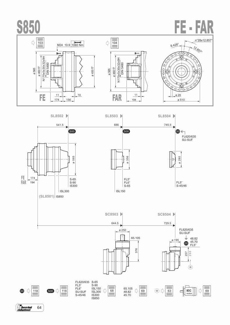
64
00
S00 00S00
0065.10548.8245.70
S00 IECmotor
FL620/635FL5”FL6”SU-SUFS-45/46
S-65S-90ISL150ISL300IS300IS850
FL620/635SU-SUF
48.8245.70FL5”
SL8502
SC8503 SC8504
SL8503 SL8504
S-65S-90IS300
FL5”S-45/46
FL620/635SU-SUF
65.105
FL5”FL6”S-65
(SL8501) IS850
ISL300 ISL150
S8501060 NmM24 10.9
11 1110
174
174
156
ø 26
ø 510
ø56
5
ø56
5
ø46
0f7
ø46
0f7
ø45
0f7
DIN
5480
541.5 686 745.5
644.5 729.5
ø 250
ø 195
ø56
5
ø35
6
ø28
0
257
29
0
N17
0x5x
30x3
2x9H
N17
0x5x
30x3
2x9H
376
6.428°12.857°
n°28x12.857°
FE - FAR
FE FAR
DIN
5480
194
FEFAR 194
118 118
103
68 69 63 69
104

65
00
S00 00S00
0065.10548.8245.70
S00 IECmotor
FL620/635FL5”FL6”SU-SUFS-45/46
S-65S-90ISL150ISL300IS300IS850
FL620/635SU-SUF
48.8245.70FL5”
SL8502
SC8503 SC8504
SL8503 SL8504
S-65S-90IS300
FL5”S-45/46
FL620/635SU-SUF
65.105
FL5”FL6”S-65
(SL8501) IS850
ISL300 ISL150
S850FS1060 NmM24 10.9
541.5 686 745.5
644.5 729.5
ø 250
ø 195
ø56
5
ø35
6
ø28
0
257
290
11 10
257
257
156
ø 26
ø 510
ø56
5ø
460
f7ø
405
ø18
0H
7
ø45
0f7
376
6.428°12.857°
n°28x12.857°105
118 118 68 69 63 69
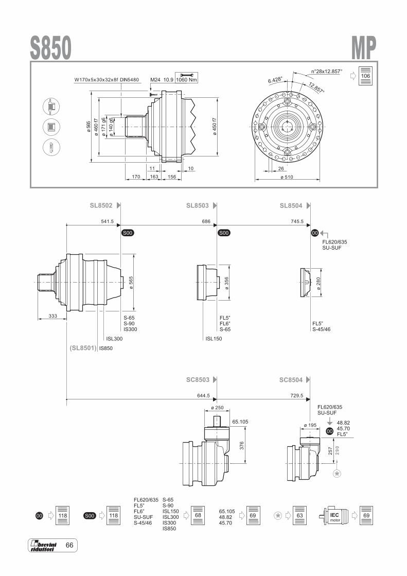
66
00
S00 00S00
FL620/635FL5”FL6”SU-SUFS-45/46
0065.10548.8245.70
S-65S-90ISL150ISL300IS300IS850
S00 IECmotor
FL620/635SU-SUF
48.8245.70FL5”
SL8502
SC8503 SC8504
SL8503 SL8504
S-65S-90IS300
FL5”S-45/46
FL620/635SU-SUF
FL5”FL6”S-65
65.105
(SL8501) IS850
ISL300 ISL150
S850 MP1060 NmM24 10.9
11 10
170 163 156
26
ø 510
333
ø 250
ø 195
ø56
5
ø35
6
ø28
0
257
290
ø56
5ø
460
f7
ø45
0f7
ø17
1g6
ø14
0g6
W170x5x30x32x8f DIN5480
376
6.428°12.857°
n°28x12.857°
541.5 686 745.5
644.5 729.5
118 118
106
68 69 63 69
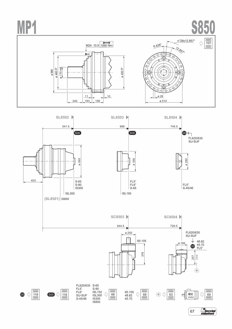
67
00
S00 00S00
0065.10548.8245.70
S00 IECmotor
FL620/635FL5”FL6”SU-SUFS-45/46
S-65S-90ISL150ISL300IS300IS850
FL620/635SU-SUF
48.8245.70FL5”
SL8502
SC8503 SC8504
SL8503 SL8504
S-65S-90IS300
FL5”S-45/46
FL620/635SU-SUF
65.105
FL5”FL6”S-65
(SL8501) IS850
ISL300 ISL150
S850MP11060 NmM24 10.9
ø 250
ø 195
ø56
5
ø35
6
ø28
0
257
290
11 10
240 163 156
ø 26
ø 510
ø56
5ø
460
f7
ø45
0f7
403
ø17
0m
6
376
6.428°12.857°
n°28x12.857°
541.5 686 745.5
644.5 729.5
107
118 118 68 69 63 69
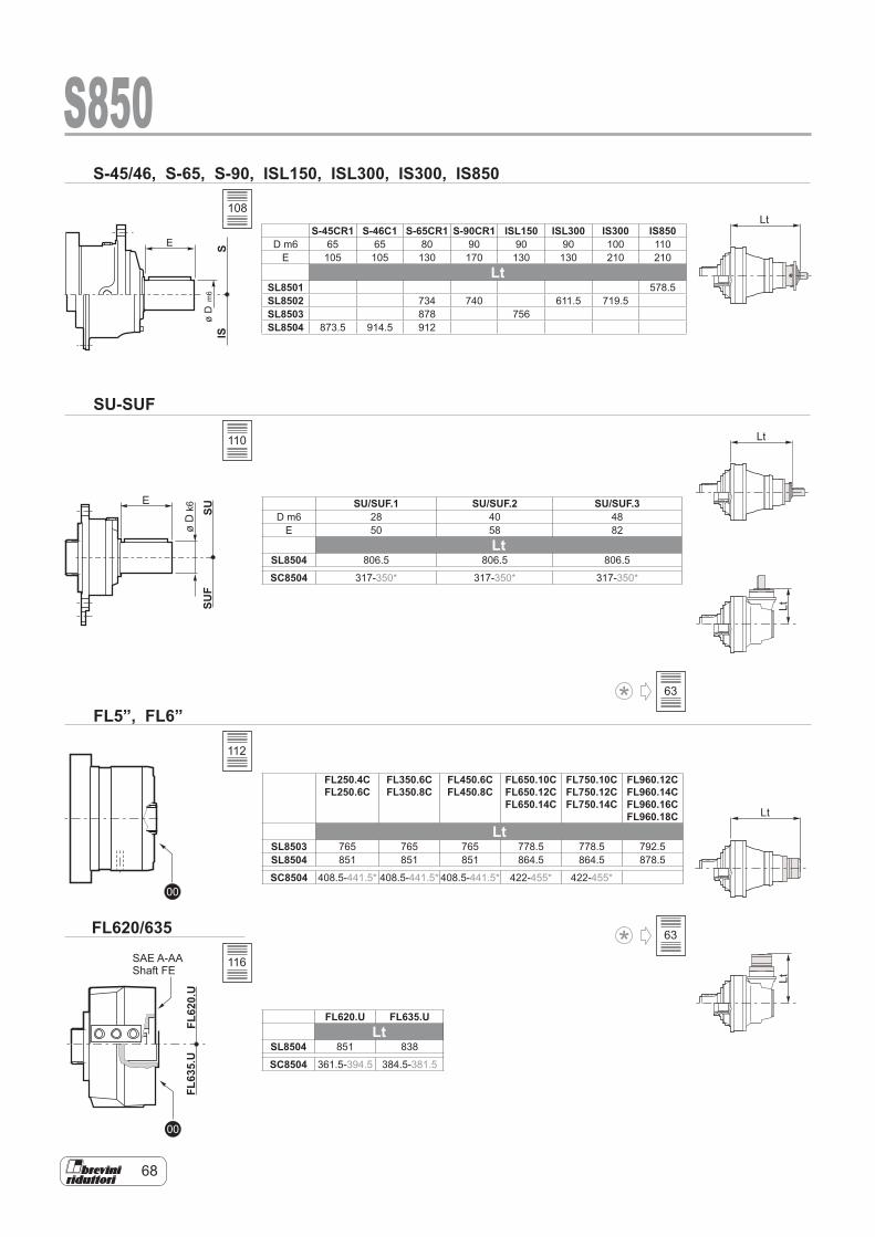
68
SUSU
F
E
øD
k6
00
00
FL62
0.U
FL63
5.U
SIS
E
øD
m6
S-45/46, S-65, S-90, ISL150, ISL300, IS300, IS850
SU-SUF
FL5”, FL6”
FL620/635
Lt
Lt
Lt
LtLt
S850
SAE A-AAShaft FE
SU/SUF.1 SU/SUF.2 SU/SUF.3D m6 28 40 48
E 50 58 82Lt
SL8504 806.5 806.5 806.5
SC8504 317-350* 317-350* 317-350*
FL250.4CFL250.6C
FL350.6C FL350.8C
FL450.6C FL450.8C
FL650.10C FL650.12C FL650.14C
FL750.10C FL750.12C FL750.14C
FL960.12C FL960.14C FL960.16C FL960.18C
LtSL8503 765 765 765 778.5 778.5 792.5SL8504 851 851 851 864.5 864.5 878.5
SC8504 408.5-441.5* 408.5-441.5* 408.5-441.5* 422-455* 422-455*
FL620.U FL635.ULt
SL8504 851 838
SC8504 361.5-394.5 384.5-381.5
S-45CR1 S-46C1 S-65CR1 S-90CR1 ISL150 ISL300 IS300 IS850D m6 65 65 80 90 90 90 100 110
E 105 105 130 170 130 130 210 210Lt
SL8501 578.5SL8502 734 740 611.5 719.5SL8503 878 756SL8504 873.5 914.5 912
108
110
112
116
63
63
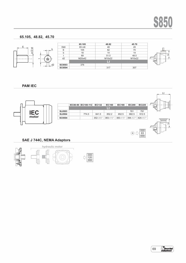
69
hydraulic motor
E
øD
k6
t
b
d2
IECmotor
Lt
LtLt
S85065.105, 48.82, 45.70
PAM IEC
SAE J 744C, NEMA Adaptors
65.105 48.82 45.70Dk6 65 m6 48 45E 105 82 70b 18 14 14t 69 51.5 48.5
d2 M20x42 M10x22 M10x22Lt
SC8503 376SC8504 317 307
IEC80-90 IEC100-112 IEC132 IEC160 IEC180 IEC200 IEC225Lt
SL8503 761 791SL8504 774.5 841.5 852.2 852.5 882.5 912.5
SC8504 352-385* 383-416* 383-416* 394-427* 424-457*
120
63

70
RDF S850MS 800FR 800
ø41
5
ø35
0
ø25
0f7
ø17
1H7
ø17
1H7
ø25
0
15
40170
25
17
25
ø32
N°12
x30°N 170-5-9H
DIN 5480
15
170
N 170-5-9HDIN 5480
ø19
0
ø14
0M7
14
ø112
ø15.5
N°3x120°
Mat.Code:
Mat.Code:
Mat.Code: 900184634704512800 39105830800
C40 UNI EN 10083 C40 UNI EN 1008339NiCrMo3 UNI EN 10083
ø171H7
ø171H7
1725
ø250h7
ø171f7
M14
N°3x120°
27
S850
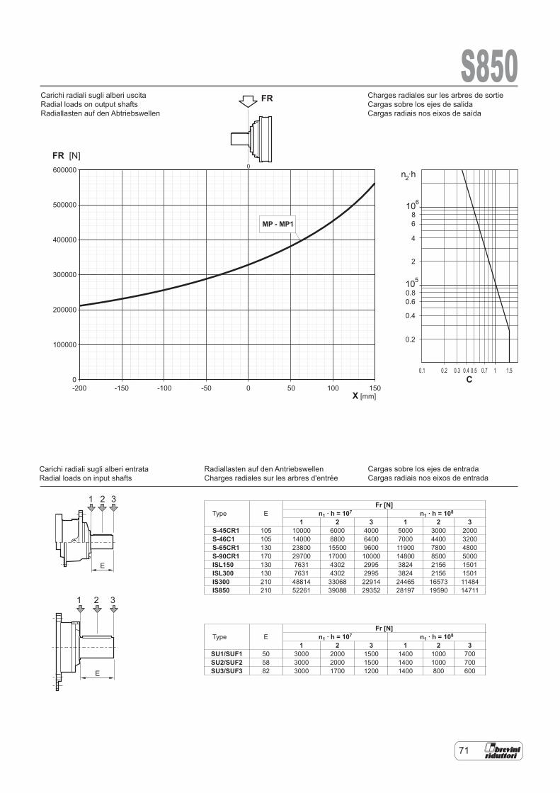
71
n ·h
10
10
2
6
5
86
4
2
0.80.6
0.4
0.2
0.20.1 0.3 0.4 0.5 0.7 1 1.5
S850
600000
500000
400000
300000
200000
100000
0-200 -150 -100 -50 0 50 100 150
FR [N]
FRCarichi radiali sugli alberi uscita
Carichi radiali sugli alberi entrata
Radial loads on output shafts
Radial loads on input shafts
X [mm]
1 2 3
E
0
1 2 3
E
C
MP - MP1
Type EFr [N]
n1 . h = 107 n1 . h = 108
1 2 3 1 2 3S-45CR1 105 10000 6000 4000 5000 3000 2000S-46C1 105 14000 8800 6400 7000 4400 3200S-65CR1 130 23800 15500 9600 11900 7800 4800S-90CR1 170 29700 17000 10000 14800 8500 5000ISL150 130 7631 4302 2995 3824 2156 1501ISL300 130 7631 4302 2995 3824 2156 1501IS300 210 48814 33068 22914 24465 16573 11484IS850 210 52261 39088 29352 28197 19590 14711
Type EFr [N]
n1 . h = 107 n1 . h = 108
1 2 3 1 2 3SU1/SUF1 50 3000 2000 1500 1400 1000 700SU2/SUF2 58 3000 2000 1500 1400 1000 700SU3/SUF3 82 3000 1700 1200 1400 800 600
Charges radiales sur les arbres de sortie Cargas sobre los ejes de salida Cargas radiais nos eixos de saída
Cargas sobre los ejes de entrada Cargas radiais nos eixos de entrada
Radiallasten auf den Antriebswellen Charges radiales sur les arbres d'entrée
Carichi radiali sugli alberi uscita Radial loads on output shafts Radiallasten auf den Abtriebswellen
Carichi radiali sugli alberi entrata Radial loads on input shafts
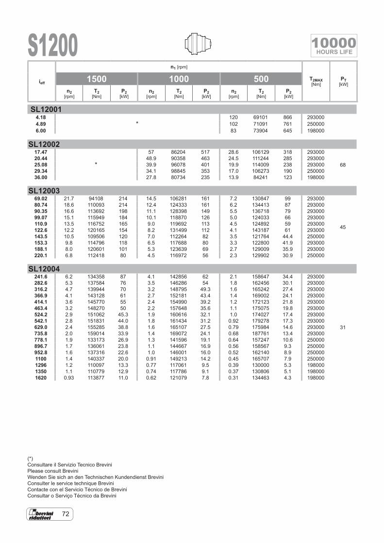
72
S1200
SL120014.18
*120 69101 866 293000
4.89 102 71091 761 2500006.00 83 73904 645 198000
SL1200217.47
*
57 86204 517 28.6 106129 318 293000
6820.44 48.9 90358 463 24.5 111244 285 29300025.08 39.9 96078 401 19.9 114009 238 29300029.34 34.1 98845 353 17.0 106273 190 25000036.00 27.8 80734 235 13.9 84241 123 198000
SL1200369.02 21.7 94108 214 14.5 106281 161 7.2 130847 99 293000
45
80.74 18.6 110093 214 12.4 124333 161 6.2 134413 87 29300090.35 16.6 113692 198 11.1 128398 149 5.5 136718 79 29300099.07 15.1 115949 184 10.1 118870 126 5.0 124033 66 293000110.9 13.5 116752 165 9.0 119692 113 4.5 124892 59 293000122.6 12.2 120165 154 8.2 131499 112 4.1 143187 61 293000143.5 10.5 109506 120 7.0 112264 82 3.5 121764 44.4 250000153.3 9.8 114796 118 6.5 117688 80 3.3 122800 41.9 293000188.1 8.0 120601 101 5.3 123639 69 2.7 129009 35.9 293000220.1 6.8 112418 80 4.5 116972 56 2.3 129902 30.9 250000
SL12004241.6 6.2 134358 87 4.1 142856 62 2.1 158647 34.4 293000
31
282.6 5.3 137584 76 3.5 146286 54 1.8 162456 30.1 293000316.2 4.7 139944 70 3.2 148795 49.3 1.6 165242 27.4 293000366.9 4.1 143128 61 2.7 152181 43.4 1.4 169002 24.1 293000414.1 3.6 145770 55 2.4 154990 39.2 1.2 172123 21.8 293000463.4 3.2 148270 50 2.2 157648 35.6 1.1 175075 19.8 293000524.2 2.9 151062 45.3 1.9 160616 32.1 1.0 174027 17.4 293000542.1 2.8 151831 44.0 1.8 161434 31.2 0.92 179278 17.3 293000629.0 2.4 155285 38.8 1.6 165107 27.5 0.79 175984 14.6 293000735.8 2.0 159014 33.9 1.4 169072 24.1 0.68 187761 13.4 293000778.1 1.9 133173 26.9 1.3 141596 19.1 0.64 157247 10.6 250000896.7 1.7 136061 23.8 1.1 144667 16.9 0.56 158567 9.3 250000952.8 1.6 137316 22.6 1.0 146001 16.0 0.52 162140 8.9 2500001100 1.4 140337 20.0 0.91 149213 14.2 0.45 165707 7.9 2500001296 1.2 110097 13.3 0.77 117061 9.5 0.39 130000 5.3 1980001350 1.1 110779 12.9 0.74 117786 9.1 0.37 130806 5.1 1980001620 0.93 113877 11.0 0.62 121079 7.8 0.31 134463 4.3 198000
ieff
n1 [rpm]
T2MAX [Nm]
PT [kW]
1500 1000 500n2
[rpm]T2
[Nm]P2
[kW]n2
[rpm]T2
[Nm]P2
[kW]n2
[rpm]T2
[Nm]P2
[kW]
(*)Consultare il Servizio Tecnico BreviniPlease consult BreviniWenden Sie sich an den Technischen Kundendienst BreviniConsulter le service technique BreviniContacte con el Servicio Técnico de BreviniConsultar o Serviço Técnico da Brevini
10000HOURS LIFE
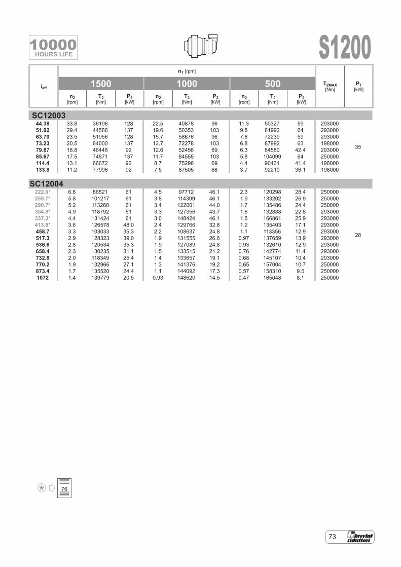
73
S1200
SC1200344.38 33.8 36196 128 22.5 40878 96 11.3 50327 59 293000
35
51.02 29.4 44586 137 19.6 50353 103 9.8 61992 64 29300063.70 23.5 51956 128 15.7 58676 96 7.8 72239 59 29300073.23 20.5 64000 137 13.7 72278 103 6.8 87992 63 19800079.67 18.8 46448 92 12.6 52456 69 6.3 64580 42.4 29300085.67 17.5 74871 137 11.7 84555 103 5.8 104099 64 250000114.4 13.1 66672 92 8.7 75296 69 4.4 90431 41.4 198000133.8 11.2 77996 92 7.5 87505 68 3.7 92210 36.1 198000
SC12004222.0* 6.8 86521 61 4.5 97712 46.1 2.3 120298 28.4 250000
28
259.7* 5.8 101217 61 3.8 114309 46.1 1.9 133202 26.9 250000290.7* 5.2 113260 61 3.4 122001 44.0 1.7 135486 24.4 250000304.8* 4.9 118792 61 3.3 127356 43.7 1.6 132888 22.8 293000337.3* 4.4 131424 61 3.0 148424 46.1 1.5 166861 25.9 293000413.8* 3.6 126578 48.0 2.4 129766 32.8 1.2 135403 17.1 293000458.7 3.3 103033 35.3 2.2 108637 24.8 1.1 113356 12.9 293000517.3 2.9 128323 39.0 1.9 131555 26.6 0.97 137659 13.9 293000536.6 2.8 120534 35.3 1.9 127089 24.8 0.93 132610 12.9 293000658.4 2.3 130235 31.1 1.5 133515 21.2 0.76 142774 11.4 293000732.8 2.0 118349 25.4 1.4 133657 19.1 0.68 145107 10.4 293000770.2 1.9 132966 27.1 1.3 141376 19.2 0.65 157004 10.7 250000873.4 1.7 135520 24.4 1.1 144092 17.3 0.57 158310 9.5 2500001072 1.4 139779 20.5 0.93 148620 14.5 0.47 165048 8.1 250000
ieff
n1 [rpm]
T2MAX [Nm]
PT [kW]
1500 1000 500n2
[rpm]T2
[Nm]P2
[kW]n2
[rpm]T2
[Nm]P2
[kW]n2
[rpm]T2
[Nm]P2
[kW]
76
10000HOURS LIFE
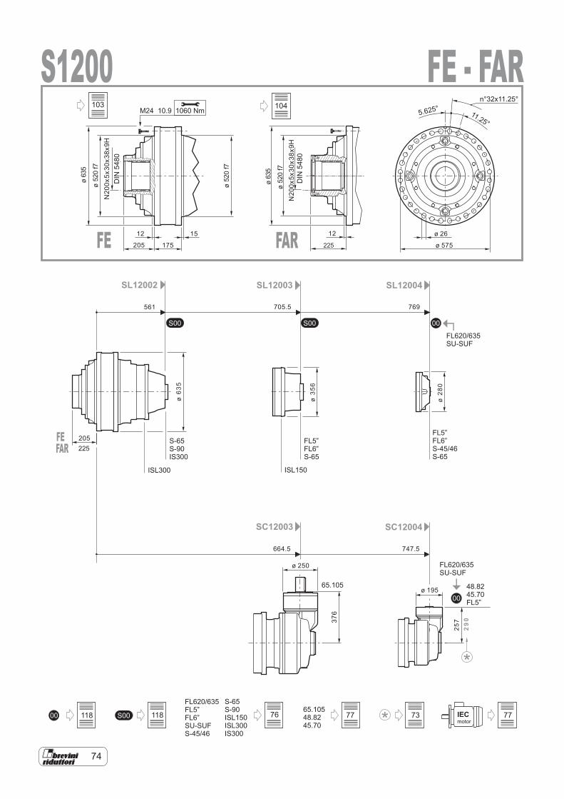
74
00
S00 00S00
FL620/635FL5”FL6”SU-SUFS-45/46
0065.10548.8245.70
S-65S-90ISL150ISL300IS300
S00 IECmotor
FL620/635SU-SUF
48.8245.70FL5”
SL12002
SC12003 SC12004
SL12003 SL12004
S-65S-90IS300
FL5”FL6”S-45/46S-65
FL620/635SU-SUF
FL5”FL6”S-65
65.105
ISL300 ISL150
S12001060 NmM24 10.9
12 1215205
205
175ø 26
ø 575
ø635
ø635
ø520f7
ø520f7
ø520f7
DIN
5480
561 705.5 769
664.5 747.5
ø 250
ø 195
ø63
5
ø35
6
ø28
0
257
29
0
11.25°5.625°
N20
0x5x
30x3
8x9H
N20
0x5x
30x3
8x9H
376
n°32x11.25°
FE - FAR
FE FAR
DIN
5480
225
FEFAR 225
118 118
103
76 77 73 77
104
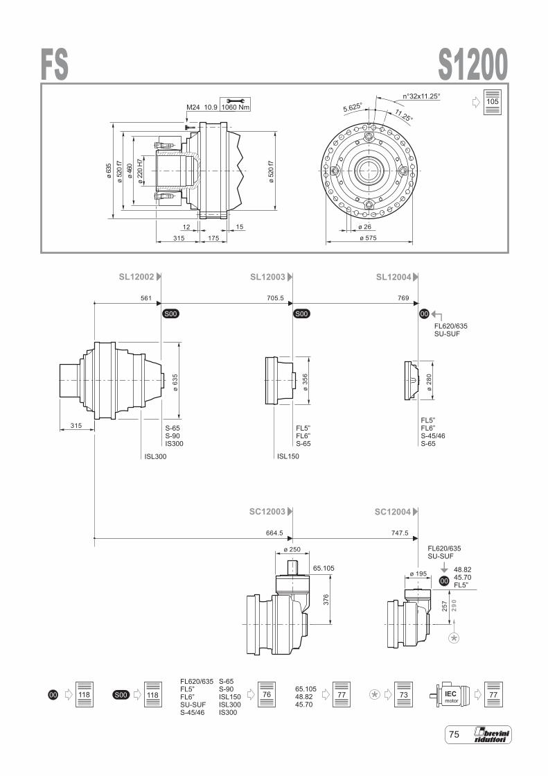
75
00
S00 00S00
0065.10548.8245.70
S00 IECmotor
FL620/635FL5”FL6”SU-SUFS-45/46
S-65S-90ISL150ISL300IS300
FL620/635SU-SUF
48.8245.70FL5”
SL12002
SC12003 SC12004
SL12003 SL12004
S-65S-90IS300
FL5”FL6”S-45/46S-65
FL620/635SU-SUF
FL5”FL6”S-65
65.105
ISL300 ISL150
S1200FS1060 NmM24 10.9
561 705.5 769
664.5 747.5
ø 250
ø 195
ø63
5
ø35
6
ø28
0
257
290
12 15
315
315
175
ø 26
ø 575
ø63
5ø
520
f7ø
460
ø22
0H
7
ø52
0f7
11.25°5.625°
376
n°32x11.25°105
118 118 76 77 73 77
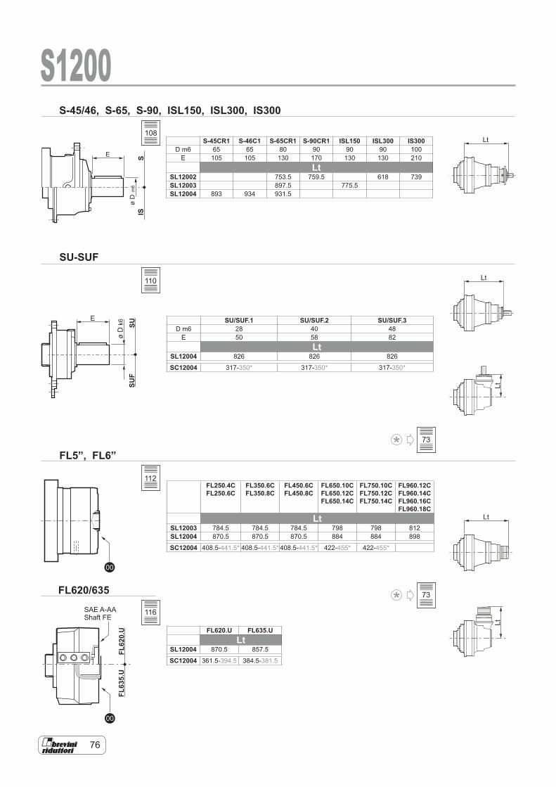
76
SUSU
F
E
øD
k6
00
00
FL62
0.U
FL63
5.U
SIS
E
øD
m6
S-45/46, S-65, S-90, ISL150, ISL300, IS300
SU-SUF
FL5”, FL6”
FL620/635
Lt
Lt
Lt
LtLt
S1200
SAE A-AAShaft FE
S-45CR1 S-46C1 S-65CR1 S-90CR1 ISL150 ISL300 IS300D m6 65 65 80 90 90 90 100
E 105 105 130 170 130 130 210Lt
SL12002 753.5 759.5 618 739SL12003 897.5 775.5SL12004 893 934 931.5
SU/SUF.1 SU/SUF.2 SU/SUF.3D m6 28 40 48
E 50 58 82Lt
SL12004 826 826 826
SC12004 317-350* 317-350* 317-350*
FL250.4CFL250.6C
FL350.6C FL350.8C
FL450.6C FL450.8C
FL650.10C FL650.12C FL650.14C
FL750.10C FL750.12C FL750.14C
FL960.12C FL960.14C FL960.16C FL960.18C
LtSL12003 784.5 784.5 784.5 798 798 812SL12004 870.5 870.5 870.5 884 884 898
SC12004 408.5-441.5* 408.5-441.5* 408.5-441.5* 422-455* 422-455*
FL620.U FL635.ULt
SL12004 870.5 857.5
SC12004 361.5-394.5 384.5-381.5
108
110
112
116
73
73
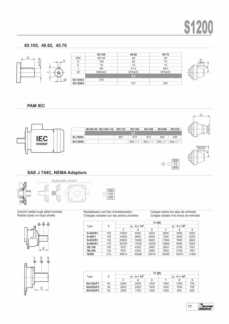
77
1 2 3
E
hydraulic motor
E
øD
k6
t
b
d2
IECmotor
1 2 3
E
Lt
LtLt
S120065.105, 48.82, 45.70
PAM IEC
SAE J 744C, NEMA Adaptors
Carichi radiali sugli alberi entrataRadial loads on input shafts
65.105 48.82 45.70Dk6 65 m6 48 45E 105 82 70b 18 14 14t 69 51.5 48.5
d2 M20x42 M10x22 M10x22Lt
SC12003 376SC12004 317 307
IEC80-90 IEC100-112 IEC132 IEC160 IEC180 IEC200 IEC225Lt
SL12004 861 872 872 902 932
SC12004 383-416* 383-416* 394-427* 424-457*
Type EFr [N]
n1 . h = 107 n1 . h = 108
1 2 3 1 2 3S-45CR1 105 10000 6000 4000 5000 3000 2000S-46C1 105 14000 8800 6400 7000 4400 3200S-65CR1 130 23800 15500 9600 11900 7800 4800S-90CR1 170 29700 17000 10000 14800 8500 5000ISL150 130 7631 4302 2995 3824 2156 1501ISL300 130 7631 4302 2995 3824 2156 1501IS300 210 48814 33068 22914 24465 16573 11484
Type EFr [N]
n1 . h = 107 n1 . h = 108
1 2 3 1 2 3SU1/SUF1 50 3000 2000 1500 1400 1000 700SU2/SUF2 58 3000 2000 1500 1400 1000 700SU3/SUF3 82 3000 1700 1200 1400 800 600
Cargas sobre los ejes de entrada Cargas radiais nos eixos de entrada
Radiallasten auf den Antriebswellen Charges radiales sur les arbres d'entrée
Carichi radiali sugli alberi entrata Radial loads on input shafts
120
73
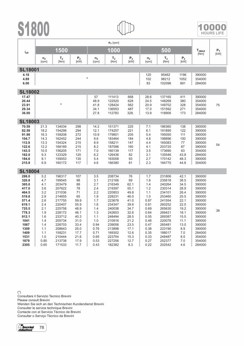
78
S1800
SL180014.18
*120 95462 1196 390000
4.89 102 98212 1052 3540006.00 83 102096 891 284000
SL1800217.47
*
57 111413 668 28.6 137165 411 390000
7520.44 48.9 122520 628 24.5 148268 380 35400023.91 41.8 128424 562 20.9 149702 328 35400029.34 34.1 136553 487 17.0 151592 271 35400036.00 27.8 112783 328. 13.9 118909 173 284000
SL1800370.59 21.3 134034 298 14.2 151371 225 7.1 186360 138 390000
54
82.58 18.2 154298 294 12.1 174257 221 6.1 191895 122 39000091.98 16.3 159208 272 10.9 179801 205 5.4 195050 111 390000104.7 14.3 162452 244 9.6 183464 184 4.8 198896 100 390000112.9 13.3 154324 215 8.9 158211 147 4.4 165083 77 390000122.6 12.2 168189 215 8.2 187096 160 4.1 203725 87 390000143.5 10.5 156205 171 7.0 160139 117 3.5 173690 63 354000162.0 9.3 123329 120 6.2 126436 82 3.1 135546 43.8 284000184.6 8.1 159053 135 5.4 163058 93 2.7 170142 48.3 390000215.9 6.9 160172 117 4.6 166380 81 2.3 184770 44.8 354000
SL18004288.0 5.2 196317 107 3.5 208734 76 1.7 231806 42.1 390000
38
320.8 4.7 199545 98 3.1 212166 69 1.6 235618 38.5 390000365.0 4.1 203479 88 2.7 216349 62.1 1.4 240264 34.5 390000417.0 3.6 207622 78 2.4 219397 55.1 1.2 230314 28.9 390000464.5 3.2 211036 71 2.2 220853 49.8 1.1 234101 26.4 390000519.8 2.9 214655 65 1.9 228231 46.0 1.0 253460 25.5 390000571.4 2.6 217755 59.9 1.7 223678 41.0 0.87 241554 22.1 390000619.1 2.4 220407 55.9 1.6 234347 39.6 0.81 260252 22.0 390000725.5 2.1 225758 48.9 1.4 240038 34.7 0.69 265630 19.2 390000778.3 1.9 228172 46.1 1.3 242603 32.6 0.64 269421 18.1 390000912.1 1.6 233712 40.3 1.1 248494 28.5 0.55 269387 15.5 3900001041 1.4 205734 31.0 1.0 210916 21.2 0.48 220078 11.1 3900001067 1.4 226703 33.4 0.94 239056 23.5 0.47 265481 13.0 3900001309 1.1 208643 25.0 0.76 213898 17.1 0.38 223190 8.9 3900001409 1.1 159231 17.7 0.71 169302 12.6 0.35 188017 7.0 2840001531 1.0 210444 21.6 0.65 223754 15.3 0.33 248487 8.5 3540001879 0.80 213738 17.9 0.53 227256 12.7 0.27 252377 7.0 3540002305 0.65 171533 11.7 0.43 182382 8.3 0.22 202542 4.6 284000
ieff
n1 [rpm]
T2MAX [Nm]
PT [kW]
1500 1000 500n2
[rpm]T2
[Nm]P2
[kW]n2
[rpm]T2
[Nm]P2
[kW]n2
[rpm]T2
[Nm]P2
[kW]
(*)Consultare il Servizio Tecnico BreviniPlease consult BreviniWenden Sie sich an den Technischen Kundendienst BreviniConsulter le service technique BreviniContacte con el Servicio Técnico de BreviniConsultar o Serviço Técnico da Brevini
10000HOURS LIFE
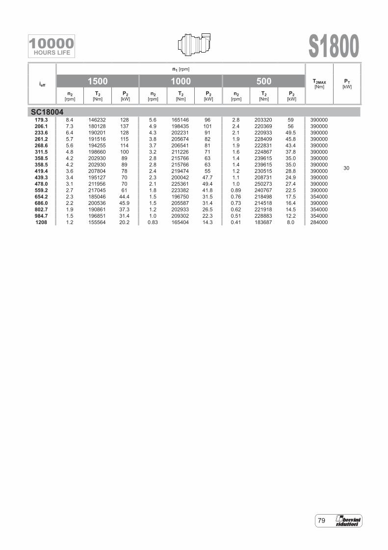
79
S1800
SC18004179.3 8.4 146232 128 5.6 165146 96 2.8 203320 59 390000
30
206.1 7.3 180128 137 4.9 198435 101 2.4 220369 56 390000233.6 6.4 190201 128 4.3 202231 91 2.1 220933 49.5 390000261.2 5.7 191516 115 3.8 205674 82 1.9 228409 45.8 390000268.6 5.6 194255 114 3.7 206541 81 1.9 222831 43.4 390000311.5 4.8 198660 100 3.2 211226 71 1.6 224867 37.8 390000358.5 4.2 202930 89 2.8 215766 63 1.4 239615 35.0 390000358.5 4.2 202930 89 2.8 215766 63 1.4 239615 35.0 390000419.4 3.6 207804 78 2.4 219474 55 1.2 230515 28.8 390000439.3 3.4 195127 70 2.3 200042 47.7 1.1 208731 24.9 390000478.0 3.1 211956 70 2.1 225361 49.4 1.0 250273 27.4 390000559.2 2.7 217045 61 1.8 223382 41.8 0.89 240767 22.5 390000654.2 2.3 185046 44.4 1.5 196750 31.5 0.76 218498 17.5 354000686.0 2.2 200536 45.9 1.5 205587 31.4 0.73 214518 16.4 390000802.7 1.9 190861 37.3 1.2 202933 26.5 0.62 221918 14.5 354000984.7 1.5 196851 31.4 1.0 209302 22.3 0.51 228883 12.2 3540001208 1.2 155564 20.2 0.83 165404 14.3 0.41 183687 8.0 284000
ieff
n1 [rpm]
T2MAX [Nm]
PT [kW]
1500 1000 500n2
[rpm]T2
[Nm]P2
[kW]n2
[rpm]T2
[Nm]P2
[kW]n2
[rpm]T2
[Nm]P2
[kW]
10000HOURS LIFE
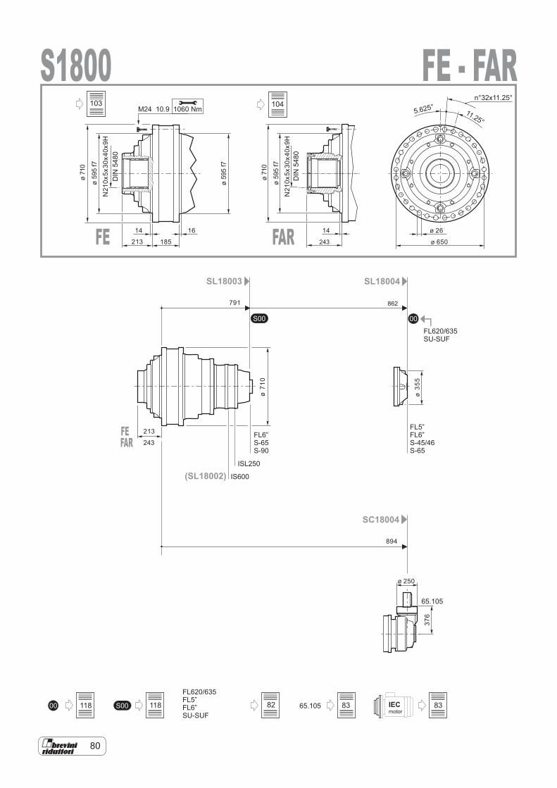
80
IECmotor
00S00
FL620/635FL5”FL6”SU-SUF
00 65.105S00
SL18003 SL18004
SC18004
FL620/635SU-SUF
65.105
FL6”S-65S-90
FL5”FL6”S-45/46S-65
(SL18002) IS600
ISL250
S18001060 NmM24 10.9
14 16
213
213
185
ø 26
ø 650
ø71
0
ø59
5f7
ø59
5f7
DIN
5480
791
894
ø 250
ø35
5
N21
0x5x
30x4
0x9H
ø71
0
376
11.25°5.625°
n°32x11.25°
862
FE - FAR
FE FAR
DIN
5480
243
ø71
0
ø59
5f7
N21
0x5x
30x4
0x9H
14
FEFAR 243
118 118
103
82 83 83
104
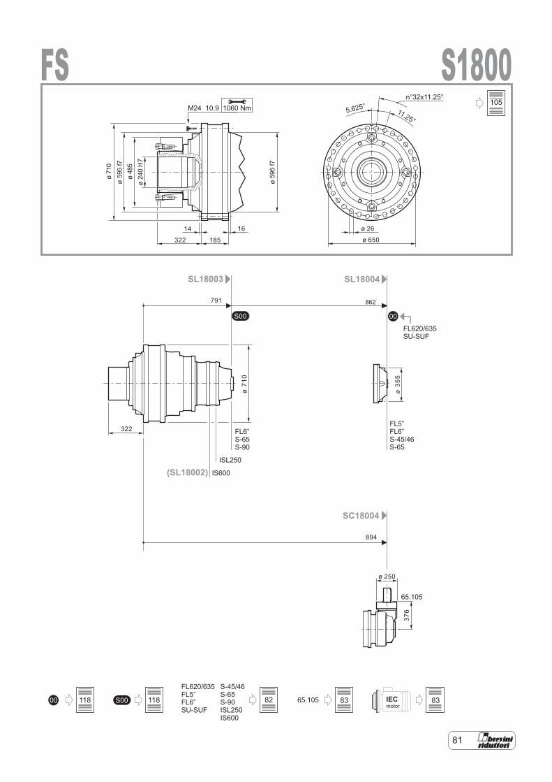
81
IECmotor
00S00
00 65.105S00
FL620/635FL5”FL6”SU-SUF
S-45/46S-65S-90ISL250IS600
SL18003 SL18004
SC18004
FL620/635SU-SUF
65.105
FL6”S-65S-90
FL5”FL6”S-45/46S-65
(SL18002)ISL250
IS600
S1800FS1060 NmM24 10.9
791
894
ø 250
ø35
5
14 16
322
322
185
ø 26
ø 650
ø71
0ø
595
f7ø
485
ø24
0H
7
ø59
5f7
ø71
0
376
11.25°5.625°
n°32x11.25°
862
105
82 83 83118118
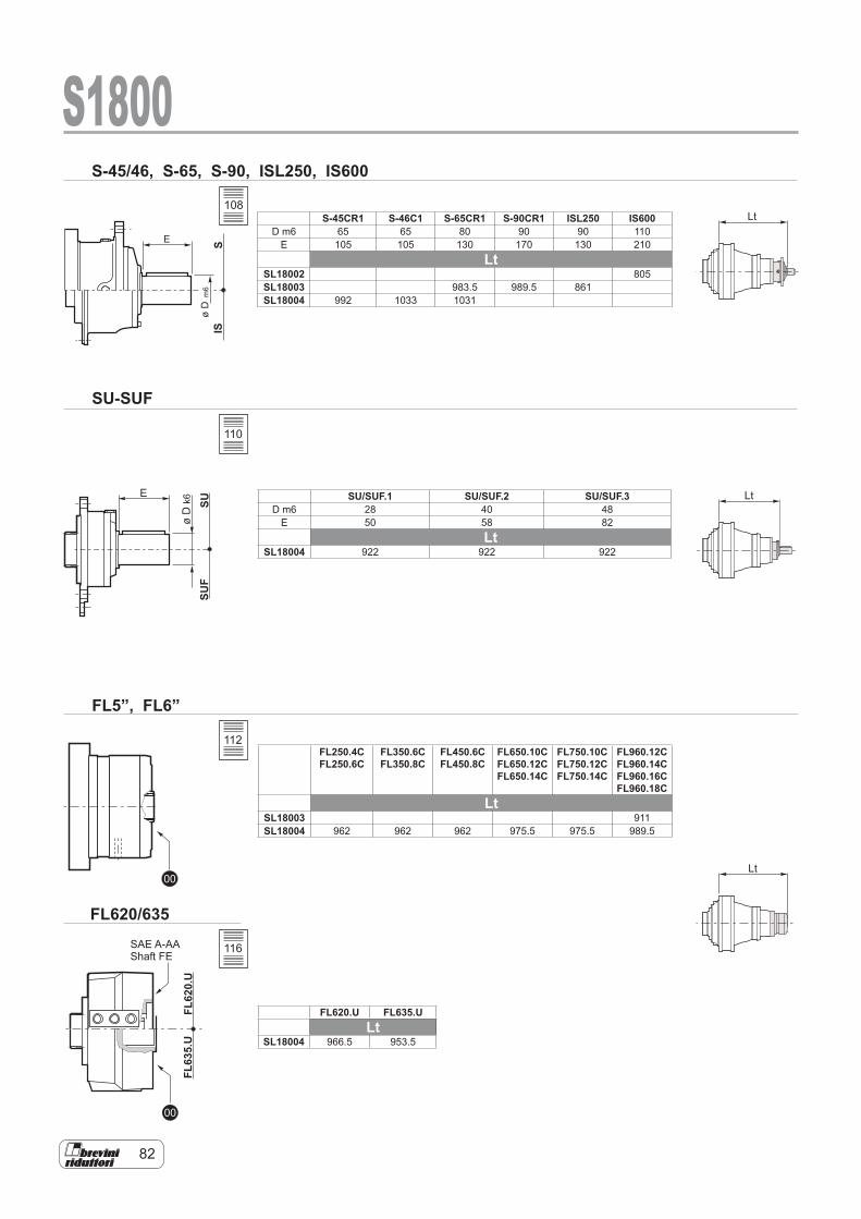
82
SUSU
F
E
øD
k6
00
00
FL62
0.U
FL63
5.U
SIS
E
øD
m6
S-45/46, S-65, S-90, ISL250, IS600
SU-SUF
FL5”, FL6”
FL620/635
Lt
Lt
Lt
S1800
SAE A-AAShaft FE
S-45CR1 S-46C1 S-65CR1 S-90CR1 ISL250 IS600D m6 65 65 80 90 90 110
E 105 105 130 170 130 210Lt
SL18002 805SL18003 983.5 989.5 861SL18004 992 1033 1031
SU/SUF.1 SU/SUF.2 SU/SUF.3D m6 28 40 48
E 50 58 82Lt
SL18004 922 922 922
FL250.4CFL250.6C
FL350.6C FL350.8C
FL450.6C FL450.8C
FL650.10C FL650.12C FL650.14C
FL750.10C FL750.12C FL750.14C
FL960.12C FL960.14C FL960.16C FL960.18C
LtSL18003 911SL18004 962 962 962 975.5 975.5 989.5
FL620.U FL635.ULt
SL18004 966.5 953.5
108
110
112
116
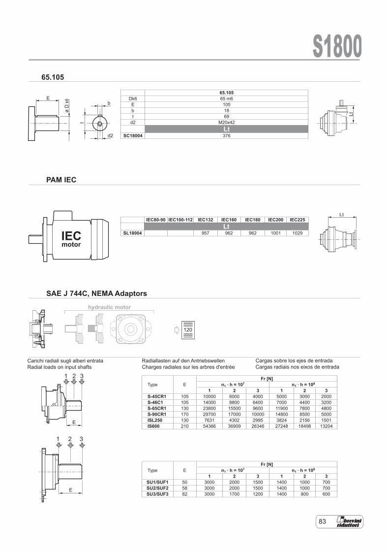
83
1 2 3
E
hydraulic motor
E
øD
k6
t
b
d2
IECmotor
1 2 3
E
Lt
Lt
S180065.105
PAM IEC
SAE J 744C, NEMA Adaptors
Carichi radiali sugli alberi entrataRadial loads on input shafts
65.105Dk6 65 m6E 105b 18t 69
d2 M20x42Lt
SC18004 376
IEC80-90 IEC100-112 IEC132 IEC160 IEC180 IEC200 IEC225Lt
SL18004 957 962 962 1001 1029
Type EFr [N]
n1 . h = 107 n1 . h = 108
1 2 3 1 2 3S-45CR1 105 10000 6000 4000 5000 3000 2000S-46C1 105 14000 8800 6400 7000 4400 3200S-65CR1 130 23800 15500 9600 11900 7800 4800S-90CR1 170 29700 17000 10000 14800 8500 5000ISL250 130 7631 4302 2995 3824 2156 1501IS600 210 54366 36909 26346 27248 18498 13204
Type EFr [N]
n1 . h = 107 n1 . h = 108
1 2 3 1 2 3SU1/SUF1 50 3000 2000 1500 1400 1000 700SU2/SUF2 58 3000 2000 1500 1400 1000 700SU3/SUF3 82 3000 1700 1200 1400 800 600
Cargas sobre los ejes de entrada Cargas radiais nos eixos de entrada
Radiallasten auf den Antriebswellen Charges radiales sur les arbres d'entrée
Carichi radiali sugli alberi entrata Radial loads on input shafts
120
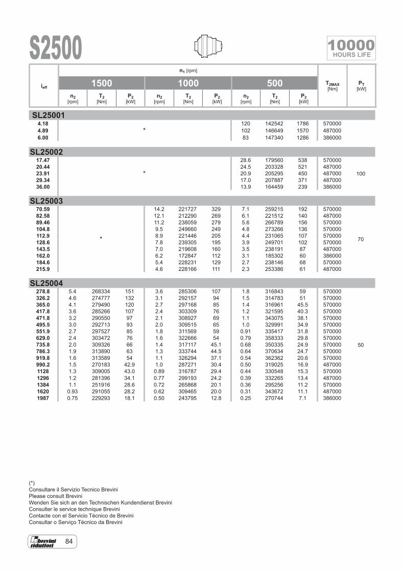
84
S2500
SL250014.18
*120 142542 1786 570000
4.89 102 146649 1570 4870006.00 83 147340 1286 386000
SL2500217.47
*
28.6 179560 538 570000
10020.44 24.5 203328 521 48700023.91 20.9 205295 450 48700029.34 17.0 207887 371 48700036.00 13.9 164459 239 386000
SL2500370.59
*
14.2 221727 329 7.1 259215 192 570000
70
82.58 12.1 212290 269 6.1 221512 140 48700089.46 11.2 238059 279 5.6 266789 156 570000104.8 9.5 249660 249 4.8 273266 136 570000112.9 8.9 221446 205 4.4 231065 107 570000128.6 7.8 239305 195 3.9 249701 102 570000143.5 7.0 219608 160 3.5 238191 87 487000162.0 6.2 172847 112 3.1 185302 60 386000184.6 5.4 228231 129 2.7 238146 68 570000215.9 4.6 228166 111 2.3 253386 61 487000
SL25004278.8 5.4 268334 151 3.6 285306 107 1.8 316843 59 570000
50
326.2 4.6 274777 132 3.1 292157 94 1.5 314783 51 570000365.0 4.1 279490 120 2.7 297168 85 1.4 316961 45.5 570000417.8 3.6 285266 107 2.4 303309 76 1.2 321595 40.3 570000471.8 3.2 290550 97 2.1 308927 69 1.1 343075 38.1 570000495.5 3.0 292713 93 2.0 309515 65 1.0 329991 34.9 570000551.9 2.7 297527 85 1.8 311569 59 0.91 335417 31.8 570000629.0 2.4 303472 76 1.6 322666 54 0.79 358333 29.8 570000735.8 2.0 309326 66 1.4 317117 45.1 0.68 350335 24.9 570000786.3 1.9 313890 63 1.3 333744 44.5 0.64 370634 24.7 570000919.8 1.6 313589 54 1.1 326294 37.1 0.54 362362 20.6 570000990.2 1.5 270183 42.9 1.0 287271 30.4 0.50 319025 16.9 4870001128 1.3 309005 43.0 0.89 316787 29.4 0.44 330548 15.3 5700001296 1.2 281396 34.1 0.77 299193 24.2 0.39 332265 13.4 4870001384 1.1 251916 28.6 0.72 265868 20.1 0.36 295256 11.2 5700001620 0.93 291055 28.2 0.62 309465 20.0 0.31 343672 11.1 4870001987 0.75 229293 18.1 0.50 243795 12.8 0.25 270744 7.1 386000
ieff
n1 [rpm]
T2MAX [Nm]
PT [kW]
1500 1000 500n2
[rpm]T2
[Nm]P2
[kW]n2
[rpm]T2
[Nm]P2
[kW]n2
[rpm]T2
[Nm]P2
[kW]
(*)Consultare il Servizio Tecnico BreviniPlease consult BreviniWenden Sie sich an den Technischen Kundendienst BreviniConsulter le service technique BreviniContacte con el Servicio Técnico de BreviniConsultar o Serviço Técnico da Brevini
10000HOURS LIFE

85
S2500
SC25004179.3 8.4 146232 128 5.6 165147 96 2.8 203320 59 570000
40
206.1 7.3 180129 137 4.9 203428 103 2.4 250449 64 570000229.6 6.5 200639 137 4.4 226590 103 2.2 278966 64 570000261.2 5.7 228282 137 3.8 257810 103 1.9 313733 63 570000268.6 5.6 234718 137 3.7 265079 103 1.9 311053 61 570000306.1 4.9 267518 137 3.3 289365 99 1.6 321350 55 570000358.1 4.2 278687 122 2.8 296313 87 1.4 316591 46.3 570000382.1 3.9 281434 116 2.6 296429 81 1.3 309306 42.4 570000439.3 3.4 287433 103 2.3 298975 71 1.1 311962 37.2 570000478.0 3.1 278687 92 2.1 309546 68 1.0 343763 37.7 570000559.2 2.7 298124 84 1.8 311822 58 0.89 336090 31.5 570000654.2 2.3 253764 61 1.5 269815 43.2 0.76 299639 24.0 487000686.0 2.2 299715 69 1.5 307263 46.9 0.73 320611 24.5 570000802.7 1.9 261739 51 1.2 278294 36.3 0.62 309056 20.2 487000984.7 1.5 269954 43.1 1.0 287028 30.5 0.51 318755 16.9 4870001208 1.2 212669 27.6 0.83 226120 19.6 0.41 251114 10.9 386000
ieff
n1 [rpm]
T2MAX [Nm]
PT [kW]
1500 1000 500n2
[rpm]T2
[Nm]P2
[kW]n2
[rpm]T2
[Nm]P2
[kW]n2
[rpm]T2
[Nm]P2
[kW]
10000HOURS LIFE
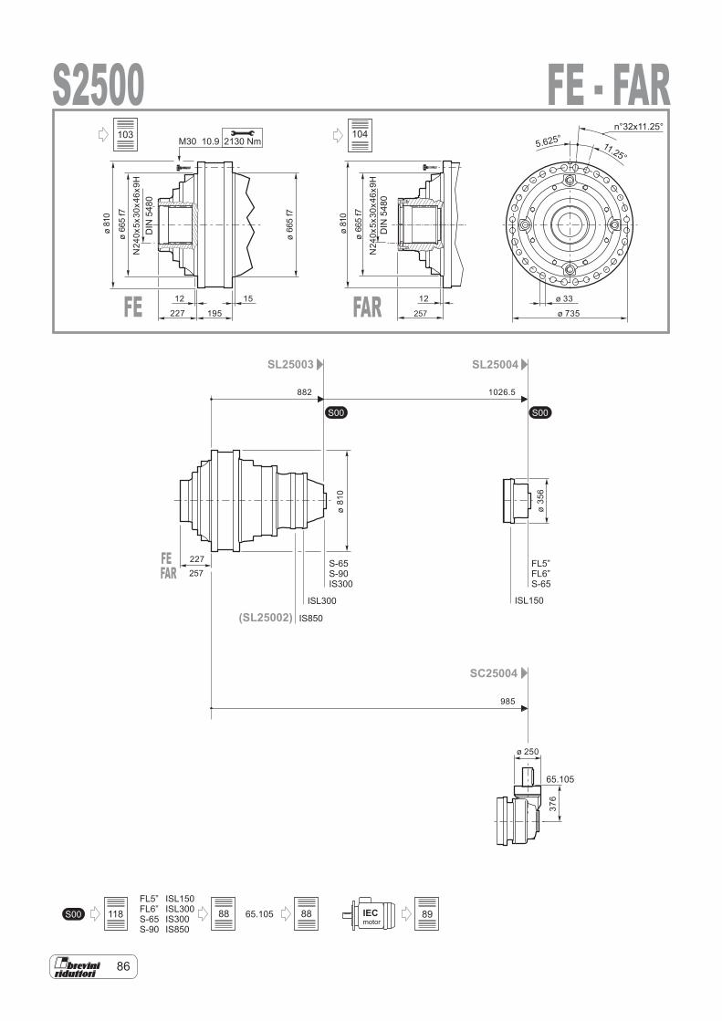
86
65.105
FL5”FL6”S-65S-90
S00
S00 S00
IECmotor
ISL150ISL300IS300IS850
SL25003 SL25004
SC25004
65.105
S-65S-90IS300
FL5”FL6”S-65
(SL25002) IS850
ISL300 ISL150
S25002130 NmM30 10.9
12 15
227
227
195
ø 33
ø 735
ø81
0
ø66
5f7
ø66
5f7
DIN
5480
882 1026.5
985
ø 250
N24
0x5x
30x4
6x9H
11.25°5.625°
n°32x11.25°
376
ø81
0
ø35
6
FE - FAR
FE FAR
DIN
5480
257
12
ø81
0
ø66
5f7
N24
0x5x
30x4
6x9H
FEFAR 257
118 88
103
88 89
104
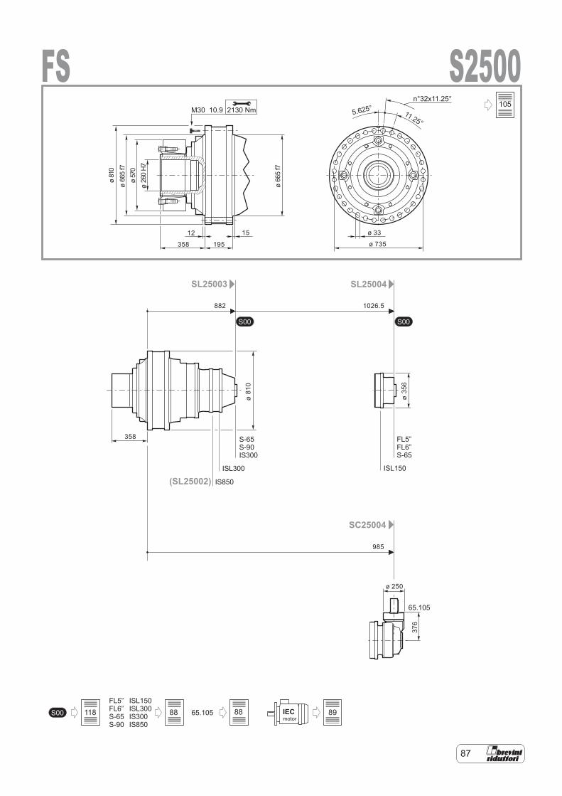
87
FL5”FL6”S-65S-90
S00 S00
65.105S00 IECmotor
ISL150ISL300IS300IS850
SL25003 SL25004
SC25004
65.105
S-65S-90IS300
FL5”FL6”S-65
(SL25002) IS850
ISL300 ISL150
S2500FS2130 NmM30 10.9
882 1026.5
985
ø 250
12 15
358
358
195
ø 33
ø 735
ø81
0ø
665
f7ø
570
ø26
0H
7
ø66
5f7
11.25°5.625°
n°32x11.25°
376
ø81
0
ø35
6
105
118 88 88 89
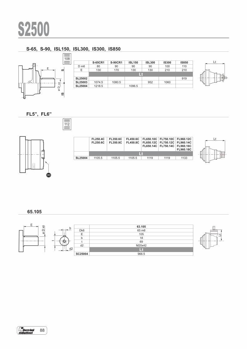
88
E
øD
k6
t
b
d2
Lt
Lt
Lt
00
SIS
E
øD
m6
S-65, S-90, ISL150, ISL300, IS300, IS850
S2500
65.105
FL5”, FL6”
S-65CR1 S-90CR1 ISL150 ISL300 IS300 IS850D m6 80 90 90 90 100 110
E 130 170 130 130 210 210Lt
SL25002 919SL25003 1074.5 1080.5 952 1060SL25004 1218.5 1096.5
FL250.4CFL250.6C
FL350.6C FL350.8C
FL450.6C FL450.8C
FL650.10C FL650.12C FL650.14C
FL750.10C FL750.12C FL750.14C
FL960.12C FL960.14C FL960.16C FL960.18C
LtSL25004 1105.5 1105.5 1105.5 1119 1119 1133
63.105Dk6 65 m6E 105b 18t 69
d2 M20x42Lt
SC25004 966.5
108
112
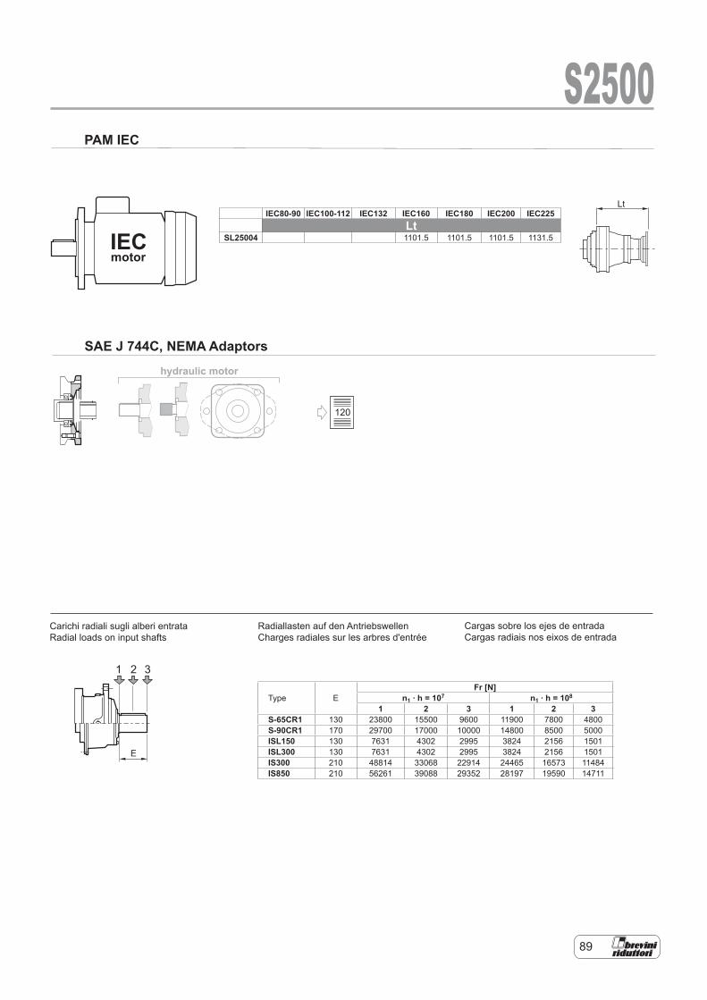
89
hydraulic motor
Lt
IECmotor
1 2 3
E
S2500PAM IEC
SAE J 744C, NEMA Adaptors
Carichi radiali sugli alberi entrataRadial loads on input shafts
IEC80-90 IEC100-112 IEC132 IEC160 IEC180 IEC200 IEC225Lt
SL25004 1101.5 1101.5 1101.5 1131.5
Type EFr [N]
n1 . h = 107 n1 . h = 108
1 2 3 1 2 3S-65CR1 130 23800 15500 9600 11900 7800 4800S-90CR1 170 29700 17000 10000 14800 8500 5000ISL150 130 7631 4302 2995 3824 2156 1501ISL300 130 7631 4302 2995 3824 2156 1501IS300 210 48814 33068 22914 24465 16573 11484IS850 210 56261 39088 29352 28197 19590 14711
Cargas sobre los ejes de entrada Cargas radiais nos eixos de entrada
Radiallasten auf den Antriebswellen Charges radiales sur les arbres d'entrée
Carichi radiali sugli alberi entrata Radial loads on input shafts
120
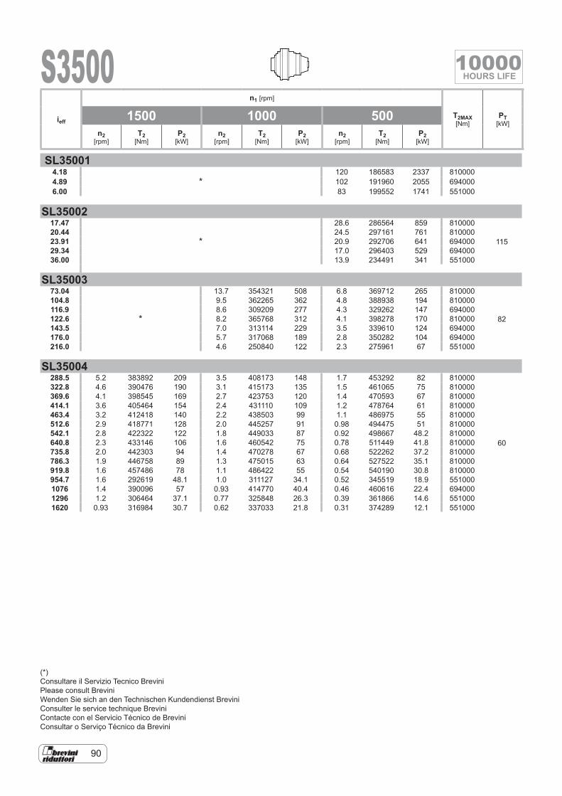
90
S3500
SL350014.18
*120 186583 2337 810000
4.89 102 191960 2055 6940006.00 83 199552 1741 551000
SL3500217.47
*
28.6 286564 859 810000
11520.44 24.5 297161 761 81000023.91 20.9 292706 641 69400029.34 17.0 296403 529 69400036.00 13.9 234491 341 551000
SL3500373.04
*
13.7 354321 508 6.8 369712 265 810000
82
104.8 9.5 362265 362 4.8 388938 194 810000116.9 8.6 309209 277 4.3 329262 147 694000122.6 8.2 365768 312 4.1 398278 170 810000143.5 7.0 313114 229 3.5 339610 124 694000176.0 5.7 317068 189 2.8 350282 104 694000216.0 4.6 250840 122 2.3 275961 67 551000
SL35004288.5 5.2 383892 209 3.5 408173 148 1.7 453292 82 810000
60
322.8 4.6 390476 190 3.1 415173 135 1.5 461065 75 810000369.6 4.1 398545 169 2.7 423753 120 1.4 470593 67 810000414.1 3.6 405464 154 2.4 431110 109 1.2 478764 61 810000463.4 3.2 412418 140 2.2 438503 99 1.1 486975 55 810000512.6 2.9 418771 128 2.0 445257 91 0.98 494475 51 810000542.1 2.8 422322 122 1.8 449033 87 0.92 498667 48.2 810000640.8 2.3 433146 106 1.6 460542 75 0.78 511449 41.8 810000735.8 2.0 442303 94 1.4 470278 67 0.68 522262 37.2 810000786.3 1.9 446758 89 1.3 475015 63 0.64 527522 35.1 810000919.8 1.6 457486 78 1.1 486422 55 0.54 540190 30.8 810000954.7 1.6 292619 48.1 1.0 311127 34.1 0.52 345519 18.9 5510001076 1.4 390096 57 0.93 414770 40.4 0.46 460616 22.4 6940001296 1.2 306464 37.1 0.77 325848 26.3 0.39 361866 14.6 5510001620 0.93 316984 30.7 0.62 337033 21.8 0.31 374289 12.1 551000
ieff
n1 [rpm]
T2MAX [Nm]
PT [kW]
1500 1000 500n2
[rpm]T2
[Nm]P2
[kW]n2
[rpm]T2
[Nm]P2
[kW]n2
[rpm]T2
[Nm]P2
[kW]
(*)Consultare il Servizio Tecnico BreviniPlease consult BreviniWenden Sie sich an den Technischen Kundendienst BreviniConsulter le service technique BreviniContacte con el Servicio Técnico de BreviniConsultar o Serviço Técnico da Brevini
10000HOURS LIFE
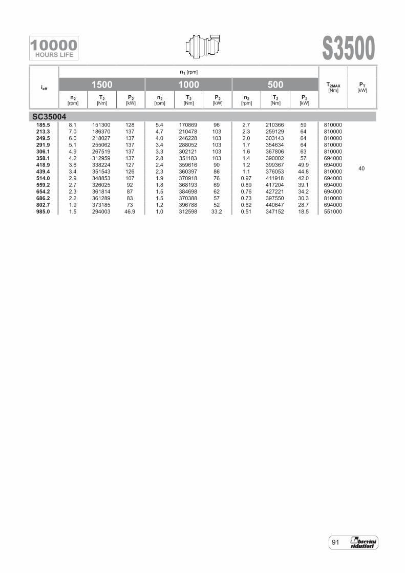
91
S3500
SC35004185.5 8.1 151300 128 5.4 170869 96 2.7 210366 59 810000
40
213.3 7.0 186370 137 4.7 210478 103 2.3 259129 64 810000249.5 6.0 218027 137 4.0 246228 103 2.0 303143 64 810000291.9 5.1 255062 137 3.4 288052 103 1.7 354634 64 810000306.1 4.9 267519 137 3.3 302121 103 1.6 367806 63 810000358.1 4.2 312959 137 2.8 351183 103 1.4 390002 57 694000418.9 3.6 338224 127 2.4 359616 90 1.2 399367 49.9 694000439.4 3.4 351543 126 2.3 360397 86 1.1 376053 44.8 810000514.0 2.9 348853 107 1.9 370918 76 0.97 411918 42.0 694000559.2 2.7 326025 92 1.8 368193 69 0.89 417204 39.1 694000654.2 2.3 361814 87 1.5 384698 62 0.76 427221 34.2 694000686.2 2.2 361289 83 1.5 370388 57 0.73 397550 30.3 810000802.7 1.9 373185 73 1.2 396788 52 0.62 440647 28.7 694000985.0 1.5 294003 46.9 1.0 312598 33.2 0.51 347152 18.5 551000
ieff
n1 [rpm]
T2MAX [Nm]
PT [kW]
1500 1000 500n2
[rpm]T2
[Nm]P2
[kW]n2
[rpm]T2
[Nm]P2
[kW]n2
[rpm]T2
[Nm]P2
[kW]
10000HOURS LIFE
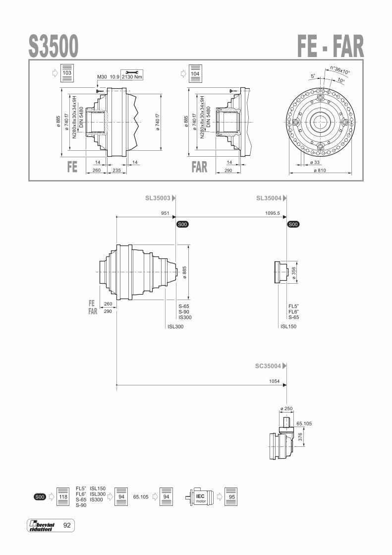
92
65.105S00
S00 S00
IECmotor
FL5”FL6”S-65S-90
ISL150ISL300IS300
SL35003 SL35004
SC35004
65.105
S-65S-90IS300
FL5”FL6”S-65
ISL300 ISL150
S35002130 NmM30 10.9
14 14
260
260
235
ø 33
ø 810
ø88
5
ø74
0f7
ø74
0f7
DIN
5480
951 1095.5
1054
ø 250
ø35
6
10°5°
n°36x10°N
280x
8x30
x34x
9H
376
ø88
5
FE - FAR
FE FAR
DIN
5480
290
14
ø88
5
ø74
0f7
N28
0x8x
30x3
4x9H
FEFAR 290
118 94
103
94 95
104
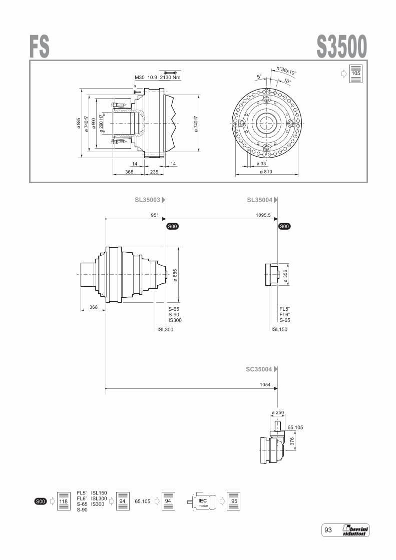
93
S00 S00
65.105S00 IECmotor
FL5”FL6”S-65S-90
ISL150ISL300IS300
SL35003 SL35004
SC35004
65.105
S-65S-90IS300
FL5”FL6”S-65
ISL300 ISL150
S3500FS2130 NmM30 10.9
951 1095.5
1054
ø 250
ø35
6
14 14
368
368
235
ø 33
ø 810
ø88
5ø
740
f7ø
590
ø29
0H
7
ø74
0f7
10°5°
n°36x10°
376
ø88
5
105
94 94 95118
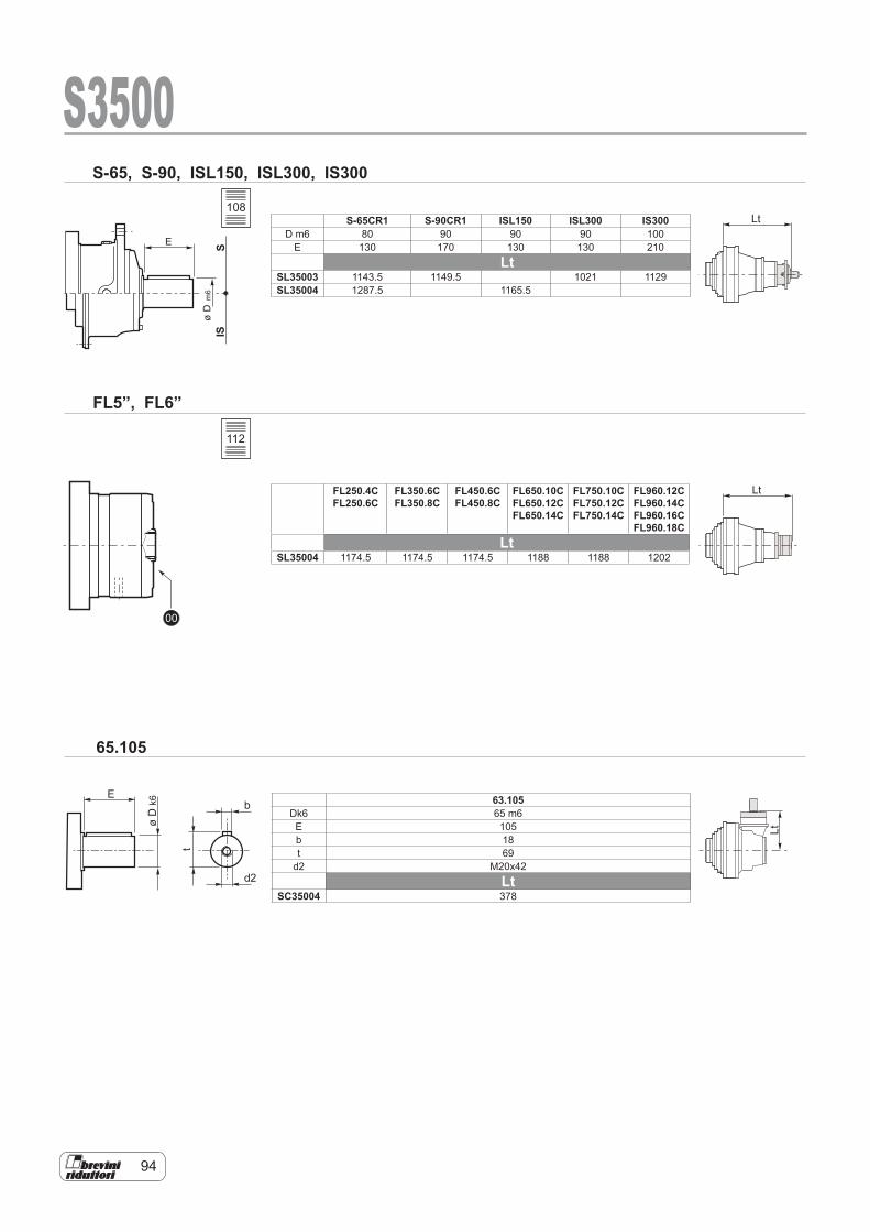
94
E
øD
k6
t
b
d2
Lt
Lt
Lt
00
SIS
E
øD
m6
S-65, S-90, ISL150, ISL300, IS300
S3500
65.105
FL5”, FL6”
S-65CR1 S-90CR1 ISL150 ISL300 IS300D m6 80 90 90 90 100
E 130 170 130 130 210Lt
SL35003 1143.5 1149.5 1021 1129SL35004 1287.5 1165.5
FL250.4CFL250.6C
FL350.6C FL350.8C
FL450.6C FL450.8C
FL650.10C FL650.12C FL650.14C
FL750.10C FL750.12C FL750.14C
FL960.12C FL960.14C FL960.16C FL960.18C
LtSL35004 1174.5 1174.5 1174.5 1188 1188 1202
63.105Dk6 65 m6E 105b 18t 69
d2 M20x42Lt
SC35004 378
108
112
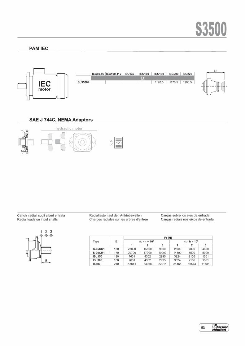
95
hydraulic motor
Lt
IECmotor
1 2 3
E
S3500PAM IEC
SAE J 744C, NEMA Adaptors
Carichi radiali sugli alberi entrataRadial loads on input shafts
IEC80-90 IEC100-112 IEC132 IEC160 IEC180 IEC200 IEC225Lt
SL35004 1170.5 1170.5 1200.5
Type EFr [N]
n1 . h = 107 n1 . h = 108
1 2 3 1 2 3S-65CR1 130 23800 15500 9600 11900 7800 4800S-90CR1 170 29700 17000 10000 14800 8500 5000ISL150 130 7631 4302 2995 3824 2156 1501ISL300 130 7631 4302 2995 3824 2156 1501IS300 210 48814 33068 22914 24465 16573 11484
Cargas sobre los ejes de entrada Cargas radiais nos eixos de entrada
Radiallasten auf den Antriebswellen Charges radiales sur les arbres d'entrée
Carichi radiali sugli alberi entrata Radial loads on input shafts
120
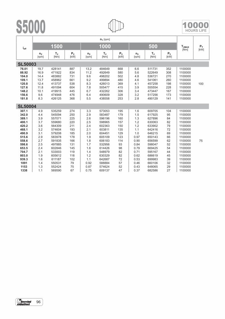
96
S5000
SL5000376.01 19.7 428141 887 13.2 484649 668 6.6 511731 352 1100000
100
88.92 16.9 471922 834 11.2 492649 580 5.6 522649 308 1100000104.0 14.4 483882 731 9.6 498202 502 4.8 536721 270 1100000109.1 13.7 458962 661 9.2 499894 480 4.6 541061 260 1100000120.8 12.4 413737 538 8.3 426013 369 4.1 457258 198 1100000127.6 11.8 491094 604 7.8 505477 415 3.9 555554 228 1100000148.2 10.1 419915 445 6.7 432262 306 3.4 473447 167 1100000156.6 9.6 474948 476 6.4 490609 328 3.2 517256 173 1100000181.8 8.3 426125 368 5.5 438558 253 2.8 490129 141 1100000
SL50004307.1 4.9 535259 274 3.3 573053 195 1.6 609705 104 1100000
75
342.0 4.4 545094 250 2.9 583487 179 1.5 617925 95 1100000389.1 3.9 557071 225 2.6 596196 160 1.3 627896 84 1100000400.1 3.7 559680 220 2.5 598965 157 1.2 630063 82 1100000420.2 3.6 564309 211 2.4 602363 150 1.2 633902 79 1100000468.1 3.2 574604 193 2.1 603811 135 1.1 642416 72 1100000490.9 3.1 579208 185 2.0 604451 129 1.0 646215 69 1100000515.6 2.9 583978 178 1.9 605109 123 0.97 650143 66 1100000558.6 2.7 591835 166 1.8 606183 114 0.90 656599 62 1100000598.6 2.5 497885 131 1.7 532956 93 0.84 598047 52 1100000653.5 2.4 602846 145 1.6 614426 98 0.79 669425 54 1100000704.7 2.1 533003 119 1.4 548979 82 0.71 595167 44 1100000803.0 1.9 605612 118 1.2 630329 82 0.62 686619 45 1100000939.3 1.6 611187 102 1.1 642687 72 0.53 699983 39 11000001091 1.4 550531 79 0.92 588884 57 0.46 660106 32 11000001153 1.3 552424 75 0.87 574624 52 0.43 648065 29 11000001338 1.1 569590 67 0.75 609137 47 0.37 682586 27 1100000
ieff
n1 [rpm]
T2MAX [Nm]
PT [kW]
1500 1000 500n2
[rpm]T2
[Nm]P2
[kW]n2
[rpm]T2
[Nm]P2
[kW]n2
[rpm]T2
[Nm]P2
[kW]
10000HOURS LIFE

97
S5000
SC50005779.9 1.9 605221 122 1100000
50
912.4 1.6 608980 105 11000001050 1.4 619616 93 11000001156 1.3 627152 85 11000001310 1.1 636900 76 11000001459 1.0 645451 70 1100000
ieff
n1 [rpm]
T2MAX [Nm]
PT [kW]
1500 1000 500n2
[rpm]T2
[Nm]P2
[kW]n2
[rpm]T2
[Nm]P2
[kW]n2
[rpm]T2
[Nm]P2
[kW]
10000HOURS LIFE
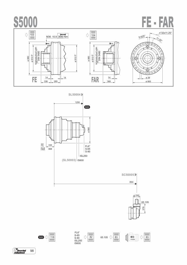
98
FL6”
IECmotor
S00
65.105S-65S-90ISL250IS600
S00
SL50004
SC50005
65.105
FL6”S-65S-90
(SL50003) IS600
ISL250
S50003680 NmM36 10.9
14
DIN
5480
894
ø 250
376
11.25°5.625°
n°32x11.25°
ø980
ø810f7
N340x8x30x41x9H
ø810f7
14
265338 ø 900
ø 39
1250
ø980
338
FE - FAR
FE FAR
DIN
5480
368
14
ø980
ø810f7
N340x8x30x41x9H
FEFAR 368
118
103
82 83 83
104
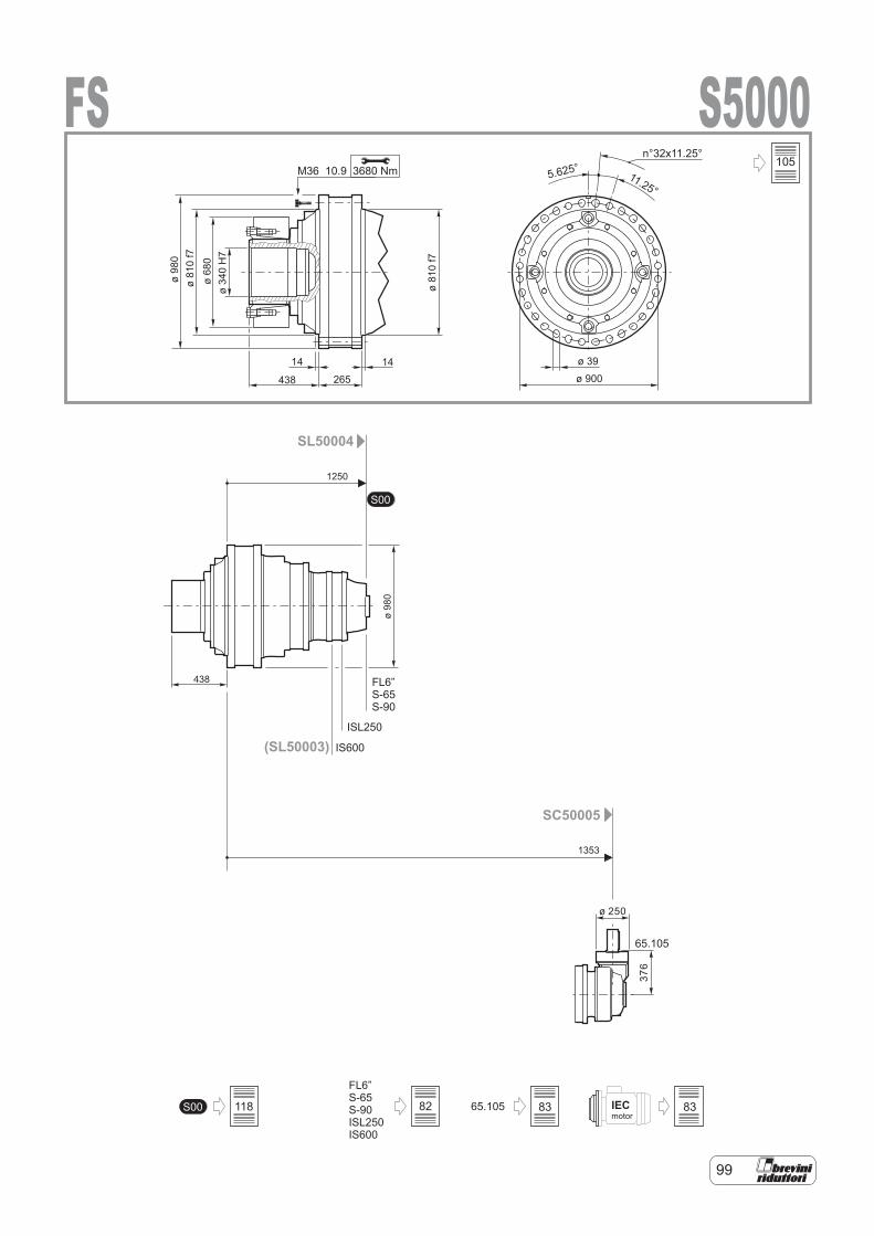
99
438
1250
1353
ø340H7
IECmotor
S00
65.105S00S-65S-90ISL250IS600
FL6”
SL50004
SC50005
65.105
FL6”S-65S-90
(SL50003)ISL250
IS600
S5000FS3680 NmM36 10.9
ø 250
14
376
11.25°5.625°
n°32x11.25°
ø980
ø810f7
ø680
ø810f7
14
265438 ø 900
ø 39
ø980
105
82 83 83118
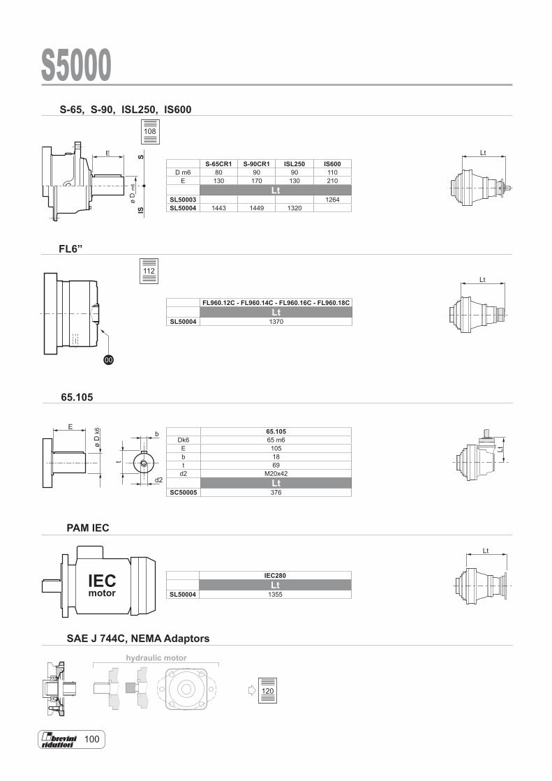
100
hydraulic motor
E
øD
k6
t
b
d2
00
IECmotor
SIS
E
øD
m6
S-65, S-90, ISL250, IS600
FL6”
Lt
Lt
Lt
Lt
S5000
65.105
PAM IEC
SAE J 744C, NEMA Adaptors
S-65CR1 S-90CR1 ISL250 IS600D m6 80 90 90 110
E 130 170 130 210Lt
SL50003 1264SL50004 1443 1449 1320
FL960.12C - FL960.14C - FL960.16C - FL960.18CLt
SL50004 1370
108
112
65.105Dk6 65 m6E 105b 18t 69
d2 M20x42Lt
SC50005 376
IEC280Lt
SL50004 1355
120

101
1 2 3
E
S5000
Type EFr [N]
n1 . h = 107 n1 . h = 108
1 2 3 1 2 3S-65CR1 130 23800 15500 9600 11900 7800 4800S-90CR1 170 29700 17000 10000 14800 8500 5000ISL250 130 7631 4302 2995 3824 2156 1501IS600 210 54366 36909 26346 27248 18498 13204
Cargas sobre los ejes de entrada Cargas radiais nos eixos de entrada
Radiallasten auf den Antriebswellen Charges radiales sur les arbres d'entrée
Carichi radiali sugli alberi entrata Radial loads on input shafts
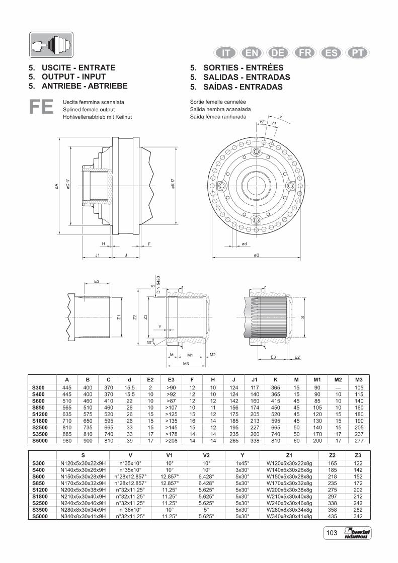
103
5. USCITE - ENTRATE5. OUTPUT - INPUT
FE Uscita femmina scanalataSplined female outputHohlwellenabtrieb mit Keilnut
DIN5480
øA øCf7
øKf7
H F
J
VV2 V1
ød
øBJ1
E3
Z2Z1 Z3
S
S
Y
30°
M M1 E3M3
M2 E2
5. ANTRIEBE - ABTRIEBE
Sortie femelle canneléeSalida hembra acanaladaSaída fêmea ranhurada
5. SORTIES - ENTRÉES5. SALIDAS - ENTRADAS5. SAÍDAS - ENTRADAS
A B C d E2 E3 F H J J1 K M M1 M2 M3S300 445 400 370 15.5 2 >90 12 10 124 117 365 15 90 — 105S400 445 400 370 15.5 10 >92 12 10 124 140 365 15 90 10 115S600 510 460 410 22 10 >87 12 12 142 160 415 45 85 10 140S850 565 510 460 26 10 >107 10 11 156 174 450 45 105 10 160S1200 635 575 520 26 15 >125 15 12 175 205 520 45 120 15 180S1800 710 650 595 26 15 >135 16 14 185 213 595 45 130 15 190S2500 810 735 665 33 15 >145 15 12 195 227 665 50 140 15 205S3500 885 810 740 33 17 >178 14 14 235 260 740 50 170 17 237S5000 980 900 810 39 17 >208 14 14 265 338 810 60 200 17 277
S V V1 V2 Y Z1 Z2 Z3S300 N120x5x30x22x9H n°35x10° 10° 10° 1x45° W120x5x30x22x8g 165 122S400 N140x5x30x26x9H n°35x10° 10° 10° 3x30° W140x5x30x26x8g 185 142S600 N150x5x30x28x9H n°28x12.857° 12.857° 6.428° 5x30° W150x5x30x28x8g 218 152S850 N170x5x30x32x9H n°28x12.857° 12.857° 6.428° 5x30° W170x5x30x32x8g 235 172S1200 N200x5x30x38x9H n°32x11.25° 11.25° 5.625° 5x30° W200x5x30x38x8g 275 202S1800 N210x5x30x40x9H n°32x11.25° 11.25° 5.625° 5x30° W210x5x30x40x8g 297 212S2500 N240x5x30x46x9H n°32x11.25° 11.25° 5.625° 5x30° W240x5x30x46x8g 338 242S3500 N280x8x30x34x9H n°36x10° 10° 5° 5x30° W280x8x30x34x8g 358 282S5000 N340x8x30x41x9H n°32x11.25° 11.25° 5.625° 5x30° W340x8x30x41x8g 435 342
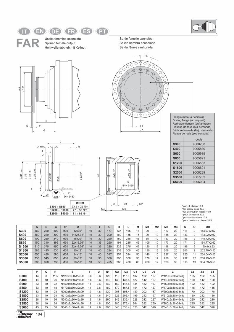
104
Uscita femmina scanalataSplined female outputHohlwellenabtrieb mit Keilnut
E F Ø d
D
ØBf7
ØA
G
H
Ø C
M M1
M3M4
S
Z
DIN 5480
DIN 5480
ØZ3H7
45° OR
NO H11 P Q R
TU
ØU1max
ØU2
ØU3h9
ØU4d10
ØU5g7
ØU6
ØZ2g7
ØZ4H7
ØL
M2
A B C d* D E F G H L M M1 M2 M3 M4 N O ORS300 360 220 300 M30 12x30° 10 30 177 137 165 15 90 — 117 20 115 9 113.97x2.62S400 360 220 300 M30 14x25.71° 10 30 200 160 185 15 90 10 135 20 133 9 133.02x2.62S600 400 260 340 M30 18x20° 10 30 220 180 218 45 85 10 157 20 155 9 145.72x2.62S850 450 310 395 M30 22x16.36° 10 35 260 194 235 45 105 10 173 20 171 9 164.77x2.62S1200 510 375 450 M30 22x16.36° 10 35 280 225 275 45 120 15 198 20 196 9 190.9x3.53S1800 585 445 530 M30 30x12° 10 40 294 233 300 45 130 15 208 20 206 9 202.79x3.53S2500 655 480 580 M36 24x15° 10 40 317 257 324 50 140 15 227 30 225 11 234.54x3.53S3500 730 545 650 M36 30x12° 10 50 360 290 358 50 170 17 259 30 257 12 266.29x3.53S5000 800 620 730 M36 36x10° 10 50 425 368 430 60 200 17 320 30 318 13 304.39x3.53
P Q R S T U U1 U2 U3 U4 U5 U6 Z Z2 Z3 Z4S300 14 8 11.5 N120x5x30x22x9H 8.6 3.6 120 115 117.8 102 122 107 W120x5x30x22x8g 105 122 105S400 14 10 26 N140x5x30x26x9H 8.6 3.6 140 130 137.8 122 142 127 W140x5x30x26x8g 120 142 120S600 33 10 22 N150x5x30x28x9H 11 3.6 160 150 147.8 134 152 137 W150x5x30x28x8g 122 152 122S850 33 10 18 N170x5x30x32x9H 11 3.6 180 170 167.8 154 172 157 W170x5x30x32x8g 145 172 145S1200 33 10 28 N200x5x30x38x9H 12 4.8 220 206 196.4 189 202 187 W200x5x30x38x8g 170 202 170S1800 33 10 28 N210x5x30x40x9H 12 4.8 240 226 206.4 199 212 197 W210x5x30x40x8g 180 212 180S2500 38 10 36 N240x5x30x46x9H 12 4.8 260 246 236.4 228 242 227 W240x5x30x46x8g 220 242 220S3500 38 10 34 N280x8x30x34x9H 12 4.8 300 280 276.4 264 282 260 W280x8x30x34x8g 235 282 235S5000 45 15 58 N340x8x30x41x9H 14 4.8 360 340 336.4 320 342 320 W340x8x30x41x8g 320 342 320
Sortie femelle canneléeSalida hembra acanaladaSaída fêmea ranhuradaFAR
codeS300 9008238S400 9005880S600 9005939S850 9005821S1200 9006563S1800 9006601S2500 9008239S3500 9007702S5000 9006094
S300 ÷ S850 23.5 ÷ 25 NmS1200 ÷ S1800 47 ÷ 50 NmS2500 ÷ S5000 81 ÷ 86 Nm
Flangia ruota (a richiesta)Driving flange (on request)Radnabenflansch (auf anfrage)Flasque de roue (sur demande)Brida se la rueda (bajo demanda)Flange de roda (sob consulta)
* per viti classe 10.9* for screw class 10.9* für Schrauben klasse 10.9 * pour vis classe 10.9* por tornillos clase 10.9* para parafusos classe 10.9
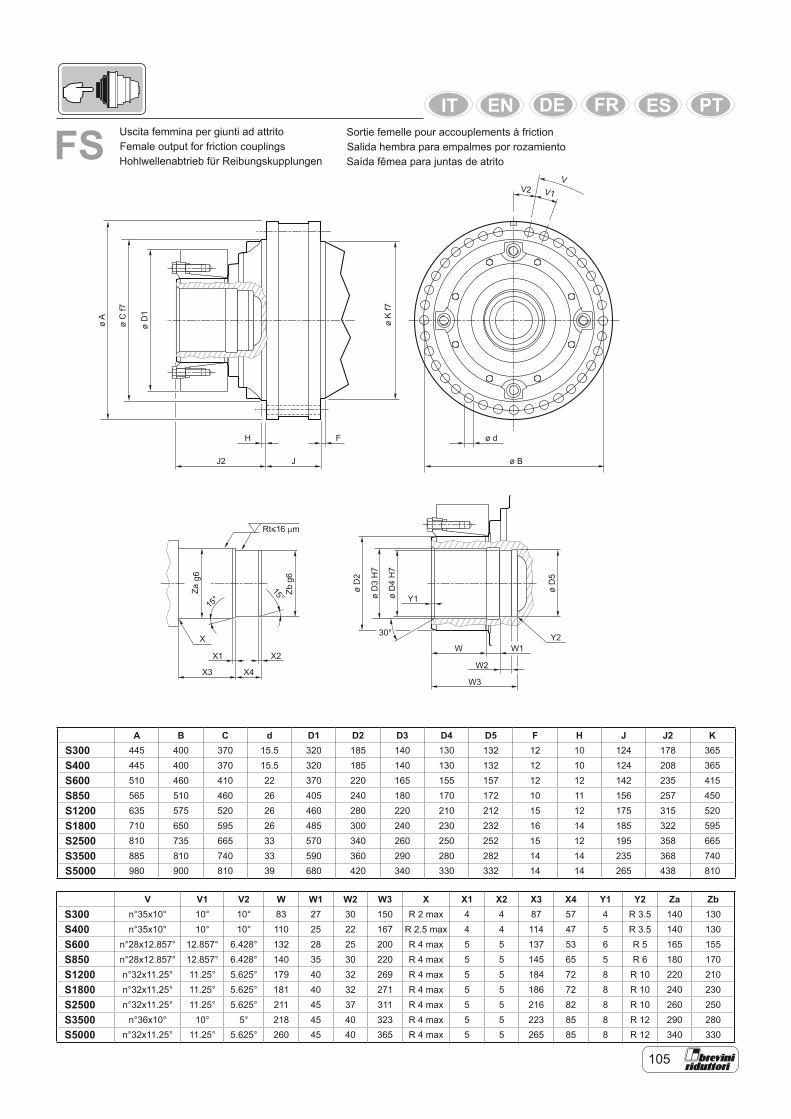
105
FS Uscita femmina per giunti ad attritoFemale output for friction couplingsHohlwellenabtrieb für Reibungskupplungen
Sortie femelle pour accouplements à frictionSalida hembra para empalmes por rozamientoSaída fêmea para juntas de atrito
A B C d D1 D2 D3 D4 D5 F H J J2 KS300 445 400 370 15.5 320 185 140 130 132 12 10 124 178 365
S400 445 400 370 15.5 320 185 140 130 132 12 10 124 208 365
S600 510 460 410 22 370 220 165 155 157 12 12 142 235 415
S850 565 510 460 26 405 240 180 170 172 10 11 156 257 450
S1200 635 575 520 26 460 280 220 210 212 15 12 175 315 520
S1800 710 650 595 26 485 300 240 230 232 16 14 185 322 595
S2500 810 735 665 33 570 340 260 250 252 15 12 195 358 665
S3500 885 810 740 33 590 360 290 280 282 14 14 235 368 740S5000 980 900 810 39 680 420 340 330 332 14 14 265 438 810
V V1 V2 W W1 W2 W3 X X1 X2 X3 X4 Y1 Y2 Za ZbS300 n°35x10° 10° 10° 83 27 30 150 R 2 max 4 4 87 57 4 R 3.5 140 130
S400 n°35x10° 10° 10° 110 25 22 167 R 2.5 max 4 4 114 47 5 R 3.5 140 130
S600 n°28x12.857° 12.857° 6.428° 132 28 25 200 R 4 max 5 5 137 53 6 R 5 165 155
S850 n°28x12.857° 12.857° 6.428° 140 35 30 220 R 4 max 5 5 145 65 5 R 6 180 170
S1200 n°32x11.25° 11.25° 5.625° 179 40 32 269 R 4 max 5 5 184 72 8 R 10 220 210
S1800 n°32x11.25° 11.25° 5.625° 181 40 32 271 R 4 max 5 5 186 72 8 R 10 240 230
S2500 n°32x11.25° 11.25° 5.625° 211 45 37 311 R 4 max 5 5 216 82 8 R 10 260 250
S3500 n°36x10° 10° 5° 218 45 40 323 R 4 max 5 5 223 85 8 R 12 290 280S5000 n°32x11.25° 11.25° 5.625° 260 45 40 365 R 4 max 5 5 265 85 8 R 12 340 330
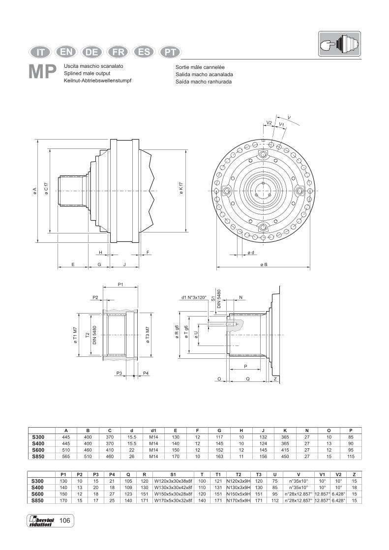
106
MPøT1M7
T2DIN5480
øT3M7
DIN5480
d1 N°3x120°
P1
P2
P3 P4
S1
øA
øCf7
øKf7
H F
E G J
VV2 V1
ø d
ø B
P
O Q
øRg6
øTg6
øU
N
Z
Uscita maschio scanalatoSplined male outputKeilnut-Abtriebswellenstumpf
Sortie mâle canneléeSalida macho acanaladaSaída macho ranhurada
A B C d d1 E F G H J K N O PS300 445 400 370 15.5 M14 130 12 117 10 132 365 27 10 85S400 445 400 370 15.5 M14 140 12 145 10 124 365 27 13 90S600 510 460 410 22 M14 150 12 152 12 145 415 27 12 95S850 565 510 460 26 M14 170 10 163 11 156 450 27 15 115
P1 P2 P3 P4 Q R S1 T T1 T2 T3 U V V1 V2 ZS300 130 10 15 21 105 120 W120x3x30x38x8f 100 121 N120x3x9H 120 75 n°35x10° 10° 10° 15S400 140 13 20 18 109 130 W130x3x30x42x8f 110 131 N130x3x9H 130 85 n°35x10° 10° 10° 18S600 150 12 18 27 123 151 W150x5x30x28x8f 120 151 N150x5x9H 151 95 n°28x12.857° 12.857° 6.428° 15S850 170 15 17 25 140 171 W170x5x30x32x8f 140 171 N170x5x9H 171 112 n°28x12.857° 12.857° 6.428° 15
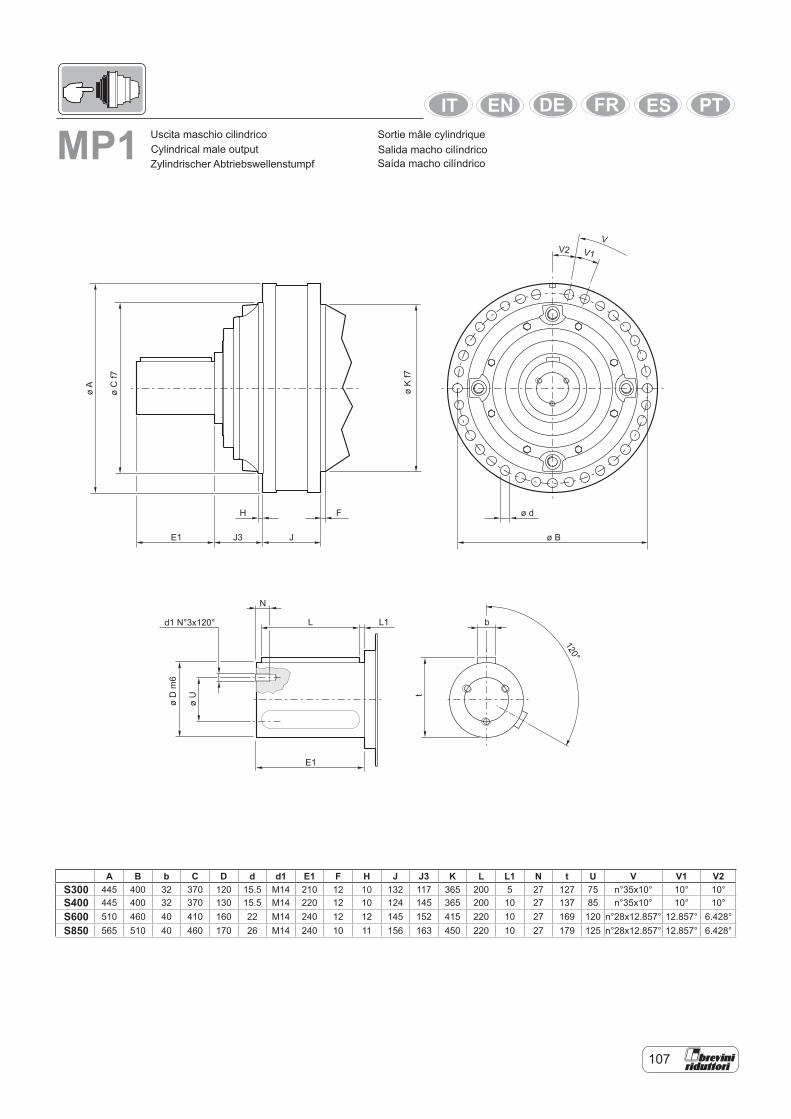
107
MP1
d1 N°3x120°
øA
øC
f7
øK
f7
H F
J
VV2 V1
ø d
ø BE1 J3
øD
m6
øU
N
L L1
E1
t
b
120°
Uscita maschio cilindricoCylindrical male outputZylindrischer Abtriebswellenstumpf
Sortie mâle cylindriqueSalida macho cilíndricoSaída macho cilíndrico
A B b C D d d1 E1 F H J J3 K L L1 N t U V V1 V2S300 445 400 32 370 120 15.5 M14 210 12 10 132 117 365 200 5 27 127 75 n°35x10° 10° 10°S400 445 400 32 370 130 15.5 M14 220 12 10 124 145 365 200 10 27 137 85 n°35x10° 10° 10°S600 510 460 40 410 160 22 M14 240 12 12 145 152 415 220 10 27 169 120 n°28x12.857° 12.857° 6.428°S850 565 510 40 460 170 26 M14 240 10 11 156 163 450 220 10 27 179 125 n°28x12.857° 12.857° 6.428°
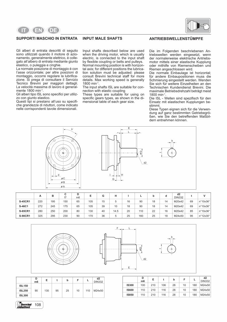
108
SUPPORTI MASCHIO IN ENTRATA
Gli alberi di entrata descritti di seguito sono utilizzati quando il motore di azio-namento, generalmente elettrico, è colle-gato all’albero di entrata mediante giunto elastico, o puleggia e cinghie.La normale posizione di montaggio è con l’asse orizzontale; per altre posizioni di montaggio, occorre regolare la lubrifica-zione. Si prega di consultare il Servizio Tecnico Brevini per maggiori dettagli. La velocità massima di lavoro è general-mente 1800 min-1.Gli alberi tipo ISL sono specifici per utiliz-zo con giunto elastico.Questi tipi si prestano all’uso su specifi-che grandezze di riduttori, come indicato nelle corrispondenti tavole dimensionali.
A B Cf7
Dm6 E G H I L b d d2
DIN332 t V
S-45CR1 220 195 150 65 105 15 5 16 90 18 14 M20x42 69 n°10x36°
S-46C1 272 245 175 65 105 39 10 18 90 18 14 M20x42 69 n°10x36°
S-65CR1 280 250 200 80 130 40 14.5 20 110 22 16 M20x42 85 n°10x36°
S-90CR1 325 295 230 90 170 36 5 25 160 25 18 M24x50 95 n°12x30°
d2
b
E
L
D t
F
INPUT MALE SHAFTS
Input shafts described below are used when the driving motor, which is usually electric, is connected to the input shaft by flexible coupling or belts and pulleys.Normal mounting position is with horizon-tal axis; for different positions the lubrica-tion solution must be adjusted: please consult Brevini technical staff for more details. Max working speed is generally 1800 min-1.The input shafts ISL are suitable for con-nection with elastic couplingThese types are suitable for using on specific gears types, as shown in the di-mensional table of each gear size.
ANTRIEBSWELLENSTÜMPFE
Die im Folgenden beschriebenen An-triebswellen werden eingesetzt, wenn der normalerweise elektrische Antriebs-motor mittels einer elastische Kupplung oder mithilfe von Riemenscheiben und Riemen angeschlossen wird. Die normale Einbaulage ist horizontal; für andere Einbaupositionen muss die Schmierung eingestellt werden. Wenden Sie sich für weitere Einzelheiten an den Technischen Kundendienst Brevini. Die maximale Betriebsdrehzahl beträgt meist 1800 min-1.Die ISL - Wellen sind spezifisch für den Einsatz mit elastischen Kupplungen be-stimmt.Diese Typen eignen sich für die Verwen-dung auf ganz bestimmten Getriebegrö-ßen, wie Sie den betreffenden Maßbil-dern entnehmen können.
D m6 E t b F L d2
DIN332ISL150
90 130 95 25 10 110 M24x50ISL250
ISL300
D m6 E t b F L d2
DIN332IS300 100 210 106 28 10 180 M24x50
IS600 110 210 116 28 10 180 M24x50
IS850 110 210 116 28 10 180 M24x50
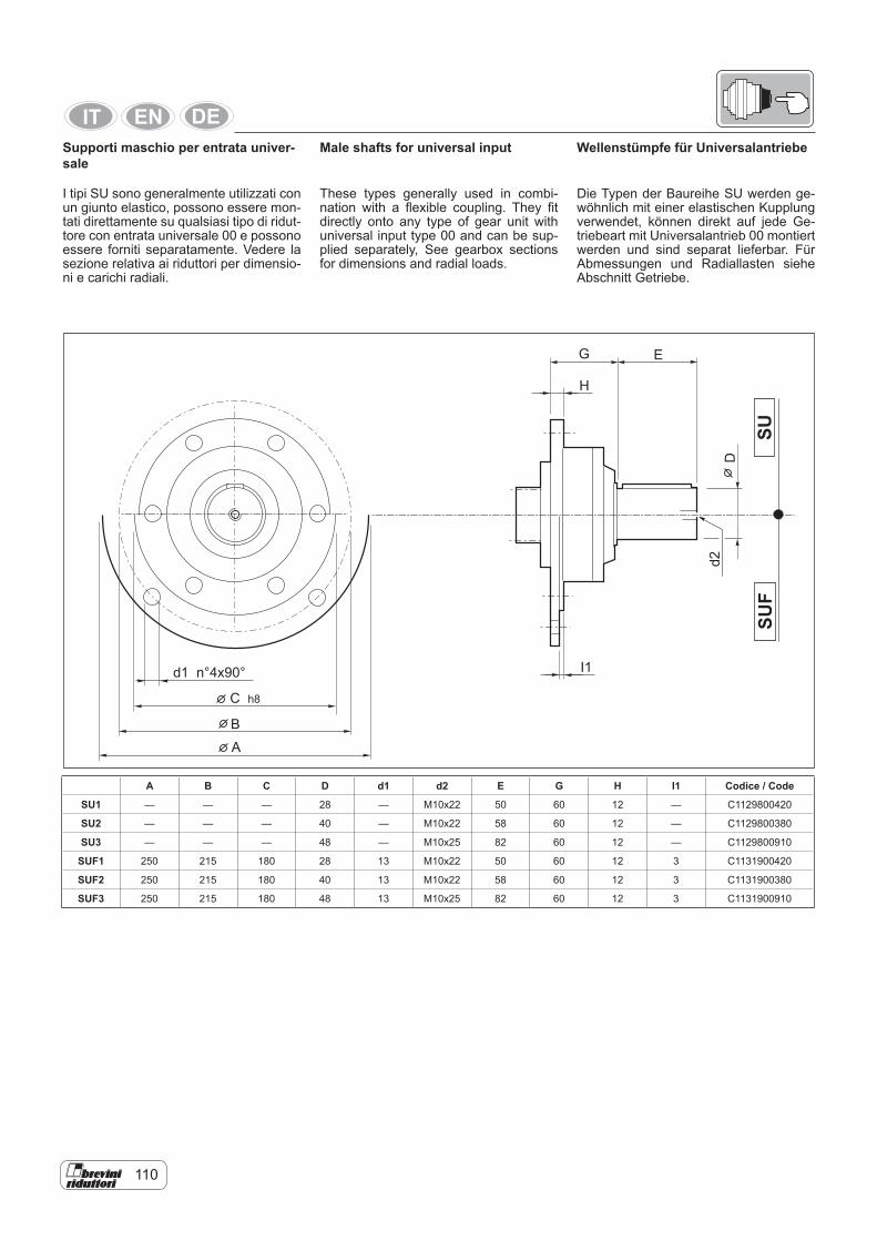
110
Male shafts for universal input
These types generally used in combi-nation with a flexible coupling. They fit directly onto any type of gear unit with universal input type 00 and can be sup-plied separately, See gearbox sections for dimensions and radial loads.
A B C D d1 d2 E G H I1 Codice / Code
SU1 — — — 28 — M10x22 50 60 12 — C1129800420
SU2 — — — 40 — M10x22 58 60 12 — C1129800380
SU3 — — — 48 — M10x25 82 60 12 — C1129800910
SUF1 250 215 180 28 13 M10x22 50 60 12 3 C1131900420
SUF2 250 215 180 40 13 M10x22 58 60 12 3 C1131900380
SUF3 250 215 180 48 13 M10x25 82 60 12 3 C1131900910
Supporti maschio per entrata univer-sale
I tipi SU sono generalmente utilizzati con un giunto elastico, possono essere mon-tati direttamente su qualsiasi tipo di ridut-tore con entrata universale 00 e possono essere forniti separatamente. Vedere la sezione relativa ai riduttori per dimensio-ni e carichi radiali.
Wellenstümpfe für Universalantriebe
Die Typen der Baureihe SU werden ge-wöhnlich mit einer elastischen Kupplung verwendet, können direkt auf jede Ge-triebeart mit Universalantrieb 00 montiert werden und sind separat lieferbar. Für Abmessungen und Radiallasten siehe Abschnitt Getriebe.
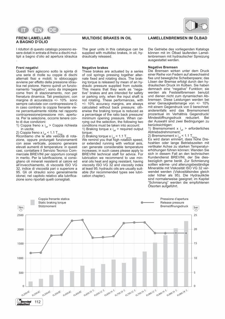
112
MULTIDISC BRAKES IN OIL
The gear units in this catalogue can be supplied with multidisc brakes, in oil, hy-draulically released.
Negative brakesThese brakes are actuated by a series of coil springs pressing together alter-nate fixed and rotating discs. The brak-ing torque is released by mean of an hy-draulic pressure supplied from outside. This means that they work as “nega-tive” brakes and are intended for safety or parking only, when the input shaft is not rotating. These performances, with +/- 10% accuracy margins, are always calculated without back pressure; oth-erwise the braking torque is reduced as a percentage of the ratio back pressure/minimum opening pressure. When car-rying out the selection, the following two conditions must be taken into account:1) Braking torque x ieff > required output torque;2) Braking torque x ieff < 1.1 T2maxWe remind you that high rotation speed, or extended running with vertical axis, can generate considerable temperature increases; in such cases please apply to BREVINI technical staff for advice. For lubrication we recommend to use min-eral oils heat and aging resistant, having viscosity ISO VG 32 and viscosity index at least 95; hydraulic oils are usually suit-able (for recommended types see lubri-cation chapter).
Coppia frenante staticaStatic braking torqueStützmoment
Pressione d’aperturaRelease pressureBremsöffnungsdruck
FL250.4C
FL250.6C
FL350.6C
FL350.8C
FL450.6C
FL450.8C
FL650.10 C
FL650.12 C
FL650.14 C
FL750.10 C
FL750.12 C
FL750.14 C
FL960.12 C
FL960.14 C
FL960.16 C
FL960.18 C
2500 25
20
15
10
5
0
2000
1500
1000
500
0
Nm bar
FRENI LAMELLARI A BAGNO D’OLIO
I riduttori di questo catalogo possono es-sere dotati in entrata di freno a dischi mul-tipli a bagno d’olio ad apertura idraulica .
Freni negativiQuesti freni agiscono sotto la spinta di una serie di molle su coppie di dischi alternati fissi e mobili; lo sbloccaggio avviene per effetto della pressione idrau-lica nel pistone. Hanno quindi un funzio-namento “negativo”; sono da impiegare come freni di stazionamento, non per frenatura dinamica. Tali prestazioni, con margine di accuratezza +/- 10% sono sempre calcolate con contropressione 0; in caso contrario la coppia frenante vie-ne percentualmente ridotta nel rapporto contropressione/pressione min. apertu-ra. Per la selezione, occorre tenere con-to di due condizioni:1) Coppia freno x ieff > Coppia richiesta in uscita;2) Coppia freno x ieff < 1.1 T2maxRicordiamo che le alte velocità di rota-zione, oppure prolungati funzionamenti con asse verticale, possono generare elevati aumenti di temperatura: in questi casi, contattare il Servizio Tecnico Com-merciale BREVINI per opportuni consigli in merito. Per la lubrificazione, si consi-gliano oli minerali resistenti al calore ed all’invecchiamento, di viscosità ISO VG 32, indice di viscosità pari o superiore a 95. Gli oli idraulici sono generalmente idonei; nel capitolo relativo alla lubrifica-zione sono riportati quelli consigliati.
LAMELLENBREMSEN IM ÖLBAD
Die Getriebe des vorliegenden Katalogs können mit im Ölbad laufenden Lamel-lenbremsen mit hydraulischer Spreizung ausgestattet werden.
Negative Bremsen Die Bremsen wirken unter dem Druck einer Reihe von Federn auf abwechselnd fixe und bewegliche Scheibenpaare; das Lösen der Bremse erfolgt durch den hy-draulischen Druck im Kolben. Sie haben demnach eine “negative” Funktion; sie werden als Feststellbremsen benutzt und dienen nicht zum dynamischen Ab-bremsen. Diese Leistungen werden bei einer Genauigkeitsmarge von +/- 10% mit einem Gegendruck von 0 berechnet; anderenfalls wird das Bremsmoment prozentual im Verhältnis Gegendruck/Mindestöffnungsdruck reduziert. Bei der Auswahl sind zwei Bedingungen zu berücksichtigen:1) Bremsmoment x ieff > erforderliches Abtriebsdrehmoment;2) Bremsmoment x ieff < 1.1 T2maxEs wird daran erinnert, dass hohe Dre-hzahlen oder lange Betriebszeiten mit vertikaler Achse zu starken Temperatur-erhöhungen führen können: Wenden Sie sich in diesem Fall an den technischen Kundendienst BREVINI, der Sie dies-bezüglich gerne berät. Zur Schmierung sollten wärme- und alterungsbeständige Mineralöle mit Viskosität ISO VG 32 ver-wendet werden (Viskositätsindex gleich oder höher als 95). Die Hydrauliköle sind normalerweise geeignet; im Kapitel “Schmierung” werden die empfohlenen Ölsorten aufgeführt.
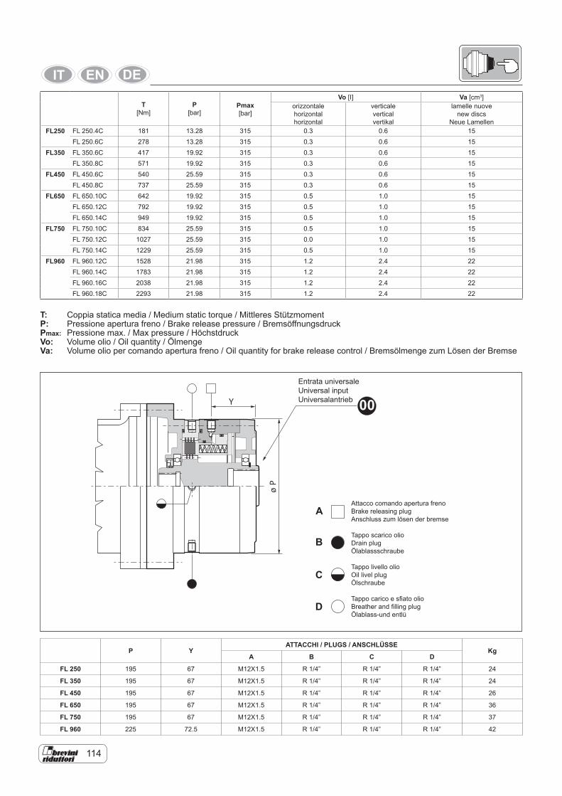
114
T: Coppia statica media / Medium static torque / Mittleres StützmomentP: Pressione apertura freno / Brake release pressure / BremsöffnungsdruckPmax: Pressione max. / Max pressure / Höchstdruck Vo: Volume olio / Oil quantity / ÖlmengeVa: Volume olio per comando apertura freno / Oil quantity for brake release control / Bremsölmenge zum Lösen der Bremse
T [Nm]
P[bar]
Pmax[bar]
Vo [I] Va [cm3]orizzontalehorizontalhorizontal
verticaleverticalvertikal
lamelle nuove new discs
Neue LamellenFL250 FL 250.4C 181 13.28 315 0.3 0.6 15
FL 250.6C 278 13.28 315 0.3 0.6 15FL350 FL 350.6C 417 19.92 315 0.3 0.6 15
FL 350.8C 571 19.92 315 0.3 0.6 15FL450 FL 450.6C 540 25.59 315 0.3 0.6 15
FL 450.8C 737 25.59 315 0.3 0.6 15FL650 FL 650.10C 642 19.92 315 0.5 1.0 15
FL 650.12C 792 19.92 315 0.5 1.0 15FL 650.14C 949 19.92 315 0.5 1.0 15
FL750 FL 750.10C 834 25.59 315 0.5 1.0 15FL 750.12C 1027 25.59 315 0.0 1.0 15FL 750.14C 1229 25.59 315 0.5 1.0 15
FL960 FL 960.12C 1528 21.98 315 1.2 2.4 22FL 960.14C 1783 21.98 315 1.2 2.4 22FL 960.16C 2038 21.98 315 1.2 2.4 22FL 960.18C 2293 21.98 315 1.2 2.4 22
P YATTACCHI / PLUGS / ANSCHLÜSSE
KgA B C D
FL 250 195 67 M12X1.5 R 1/4” R 1/4” R 1/4” 24
FL 350 195 67 M12X1.5 R 1/4” R 1/4” R 1/4” 24
FL 450 195 67 M12X1.5 R 1/4” R 1/4” R 1/4” 26
FL 650 195 67 M12X1.5 R 1/4” R 1/4” R 1/4” 36
FL 750 195 67 M12X1.5 R 1/4” R 1/4” R 1/4” 37
FL 960 225 72.5 M12X1.5 R 1/4” R 1/4” R 1/4” 42
Entrata universaleUniversal inputUniversalantrieb 00
Attacco comando apertura frenoBrake releasing plugAnschluss zum lösen der bremse
Tappo scarico olio Drain plugÖlablassschraube
Tappo livello olioOil livel plugÖlschraube
Tappo carico e sfiato olioBreather and filling plugÖlablass-und entlü
A
B
C
D
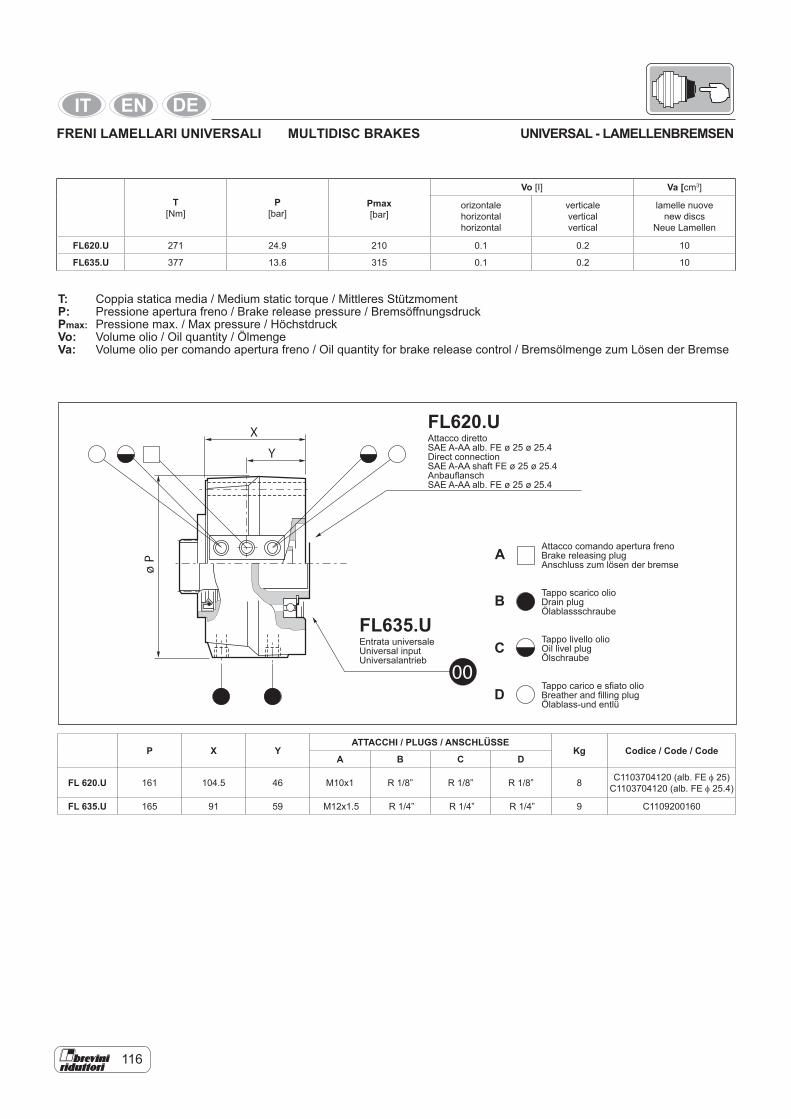
116
T [Nm]
P[bar]
Pmax[bar]
Vo [I] Va [cm3]
orizontalehorizontalhorizontal
verticaleverticalvertical
lamelle nuovenew discs
Neue Lamellen
FL620.U 271 24.9 210 0.1 0.2 10
FL635.U 377 13.6 315 0.1 0.2 10
T: Coppia statica media / Medium static torque / Mittleres StützmomentP: Pressione apertura freno / Brake release pressure / BremsöffnungsdruckPmax: Pressione max. / Max pressure / HöchstdruckVo: Volume olio / Oil quantity / ÖlmengeVa: Volume olio per comando apertura freno / Oil quantity for brake release control / Bremsölmenge zum Lösen der Bremse
FL635.UEntrata universale Universal inputUniversalantrieb
FL620.UAttacco direttoSAE A-AA alb. FE ø 25 ø 25.4Direct connectionSAE A-AA shaft FE ø 25 ø 25.4AnbauflanschSAE A-AA alb. FE ø 25 ø 25.4
P X YATTACCHI / PLUGS / ANSCHLÜSSE
Kg Codice / Code / CodeA B C D
FL 620.U 161 104.5 46 M10x1 R 1/8” R 1/8” R 1/8” 8 C1103704120 (alb. FE φ 25)C1103704120 (alb. FE φ 25.4)
FL 635.U 165 91 59 M12x1.5 R 1/4” R 1/4” R 1/4” 9 C1109200160
MULTIDISC BRAKESFRENI LAMELLARI UNIVERSALI UNIVERSAL - LAMELLENBREMSEN
Attacco comando apertura frenoBrake releasing plugAnschluss zum lösen der bremse Tappo scarico olio Drain plugÖlablassschraube
Tappo livello olioOil livel plugÖlschraube
Tappo carico e sfiato olioBreather and filling plugÖlablass-und entlü
A
B
C
D
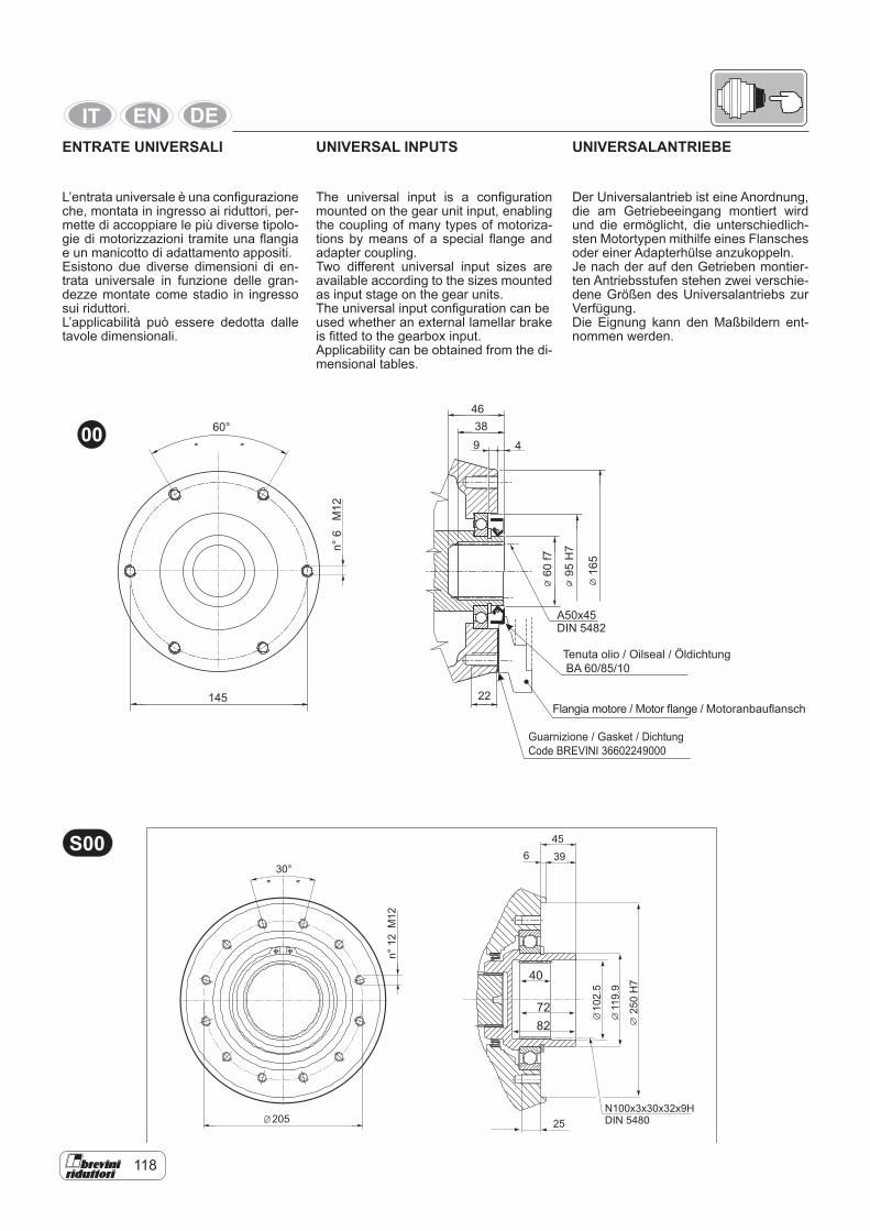
118
UNIVERSAL INPUTS
The universal input is a configuration mounted on the gear unit input, enabling the coupling of many types of motoriza-tions by means of a special flange and adapter coupling.Two different universal input sizes are available according to the sizes mounted as input stage on the gear units.The universal input configuration can be used whether an external lamellar brake is fitted to the gearbox input.Applicability can be obtained from the di-mensional tables.
456 39
40
72 102.
5
N100x3x30x32x9HDIN 5480
119.
925
0H
7
82
- -- -30°
205 25
n°12
M12
S00
ENTRATE UNIVERSALI
L’entrata universale è una configurazione che, montata in ingresso ai riduttori, per-mette di accoppiare le più diverse tipolo-gie di motorizzazioni tramite una flangia e un manicotto di adattamento appositi.Esistono due diverse dimensioni di en-trata universale in funzione delle gran-dezze montate come stadio in ingresso sui riduttori.L’applicabilità può essere dedotta dalle tavole dimensionali.
UNIVERSALANTRIEBE
Der Universalantrieb ist eine Anordnung, die am Getriebeeingang montiert wird und die ermöglicht, die unterschiedlich-sten Motortypen mithilfe eines Flansches oder einer Adapterhülse anzukoppeln.Je nach der auf den Getrieben montier-ten Antriebsstufen stehen zwei verschie-dene Größen des Universalantriebs zur Verfügung.Die Eignung kann den Maßbildern ent-nommen werden.
00
Flangia motore / Motor flange / Motoranbauflansch
Tenuta olio / Oilseal / Öldichtung BA 60/85/10
Guarnizione / Gasket / DichtungCode BREVINI 36602249000
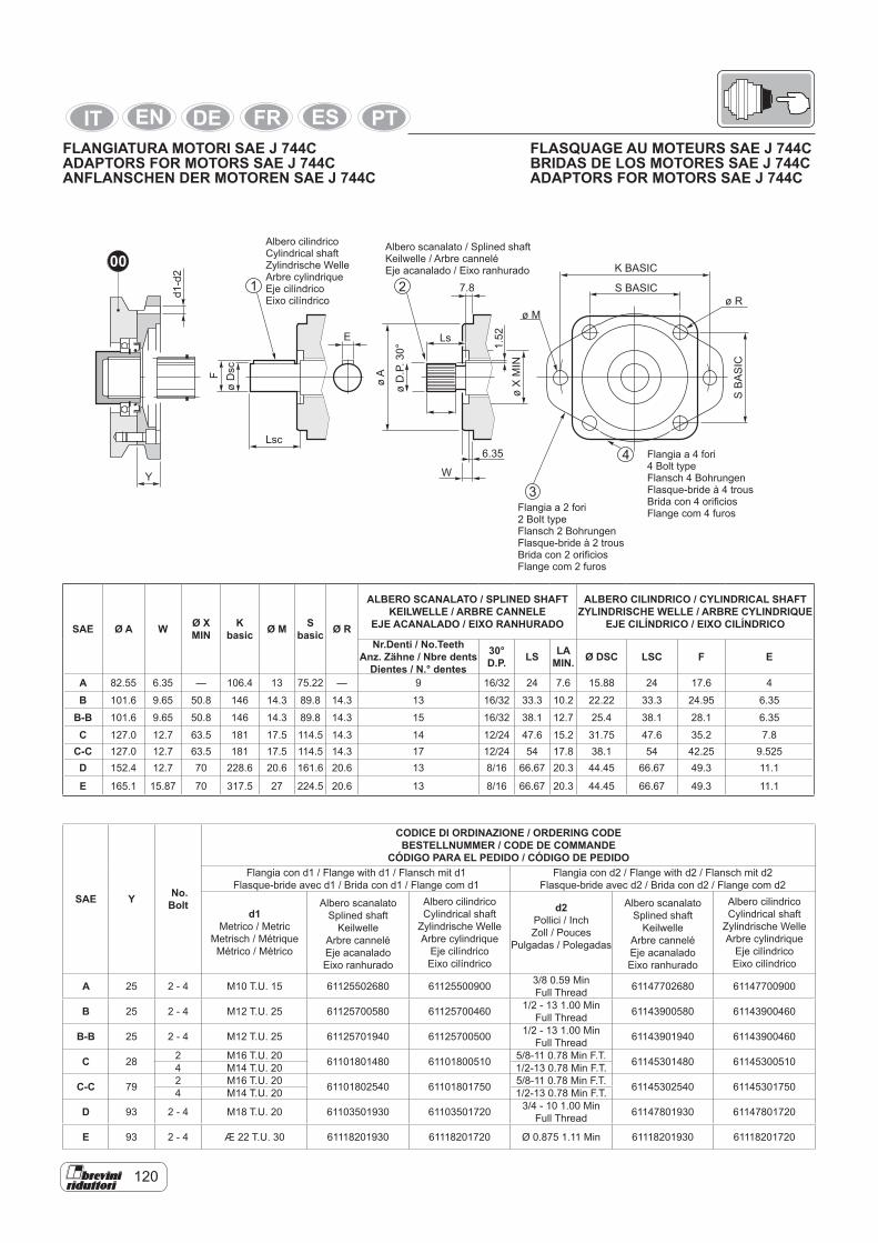
120
Albero cilindricoCylindrical shaftZylindrische WelleArbre cylindriqueEje cilíndricoEixo cilíndrico
Albero scanalato / Splined shaftKeilwelle / Arbre canneléEje acanalado / Eixo ranhurado
Flangia a 4 fori4 Bolt typeFlansch 4 BohrungenFlasque-bride à 4 trousBrida con 4 orificiosFlange com 4 furos
SAE Ø A W Ø XMIN
Kbasic Ø M S
basic Ø R
ALBERO SCANALATO / SPLINED SHAFTKEILWELLE / ARBRE CANNELE
EJE ACANALADO / EIXO RANHURADO
ALBERO CILINDRICO / CYLINDRICAL SHAFTZYLINDRISCHE WELLE / ARBRE CYLINDRIQUE
EJE CILÍNDRICO / EIXO CILÍNDRICO
Nr.Denti / No.TeethAnz. Zähne / Nbre dents
Dientes / N.° dentes
30°D.P. LS LA
MIN. Ø DSC LSC F E
A 82.55 6.35 — 106.4 13 75.22 — 9 16/32 24 7.6 15.88 24 17.6 4
B 101.6 9.65 50.8 146 14.3 89.8 14.3 13 16/32 33.3 10.2 22.22 33.3 24.95 6.35
B-B 101.6 9.65 50.8 146 14.3 89.8 14.3 15 16/32 38.1 12.7 25.4 38.1 28.1 6.35
C 127.0 12.7 63.5 181 17.5 114.5 14.3 14 12/24 47.6 15.2 31.75 47.6 35.2 7.8C-C 127.0 12.7 63.5 181 17.5 114.5 14.3 17 12/24 54 17.8 38.1 54 42.25 9.525D 152.4 12.7 70 228.6 20.6 161.6 20.6 13 8/16 66.67 20.3 44.45 66.67 49.3 11.1
E 165.1 15.87 70 317.5 27 224.5 20.6 13 8/16 66.67 20.3 44.45 66.67 49.3 11.1
SAE Y No.Bolt
CODICE DI ORDINAZIONE / ORDERING CODEBESTELLNUMMER / CODE DE COMMANDE
CÓDIGO PARA EL PEDIDO / CÓDIGO DE PEDIDOFlangia con d1 / Flange with d1 / Flansch mit d1
Flasque-bride avec d1 / Brida con d1 / Flange com d1Flangia con d2 / Flange with d2 / Flansch mit d2
Flasque-bride avec d2 / Brida con d2 / Flange com d2
d1Metrico / Metric
Metrisch / Métrique Métrico / Métrico
Albero scanalatoSplined shaft
KeilwelleArbre canneléEje acanaladoEixo ranhurado
Albero cilindricoCylindrical shaft
Zylindrische WelleArbre cylindrique
Eje cilíndricoEixo cilíndrico
d2Pollici / Inch Zoll / Pouces
Pulgadas / Polegadas
Albero scanalatoSplined shaft
KeilwelleArbre canneléEje acanaladoEixo ranhurado
Albero cilindricoCylindrical shaft
Zylindrische WelleArbre cylindrique
Eje cilíndricoEixo cilíndrico
A 25 2 - 4 M10 T.U. 15 61125502680 61125500900 3/8 0.59 MinFull Thread 61147702680 61147700900
B 25 2 - 4 M12 T.U. 25 61125700580 61125700460 1/2 - 13 1.00 MinFull Thread 61143900580 61143900460
B-B 25 2 - 4 M12 T.U. 25 61125701940 61125700500 1/2 - 13 1.00 MinFull Thread 61143901940 61143900460
C 28 2 M16 T.U. 20 61101801480 61101800510 5/8-11 0.78 Min F.T. 61145301480 611453005104 M14 T.U. 20 1/2-13 0.78 Min F.T.
C-C 79 2 M16 T.U. 20 61101802540 61101801750 5/8-11 0.78 Min F.T. 61145302540 611453017504 M14 T.U. 20 1/2-13 0.78 Min F.T.
D 93 2 - 4 M18 T.U. 20 61103501930 61103501720 3/4 - 10 1.00 Min Full Thread 61147801930 61147801720
E 93 2 - 4 Æ 22 T.U. 30 61118201930 61118201720 Ø 0.875 1.11 Min 61118201930 61118201720
FLASQUAGE AU MOTEURS SAE J 744CBRIDAS DE LOS MOTORES SAE J 744C ADAPTORS FOR MOTORS SAE J 744C
FLANGIATURA MOTORI SAE J 744C ADAPTORS FOR MOTORS SAE J 744CANFLANSCHEN DER MOTOREN SAE J 744C
Flangia a 2 fori2 Bolt typeFlansch 2 BohrungenFlasque-bride à 2 trousBrida con 2 orificiosFlange com 2 furos
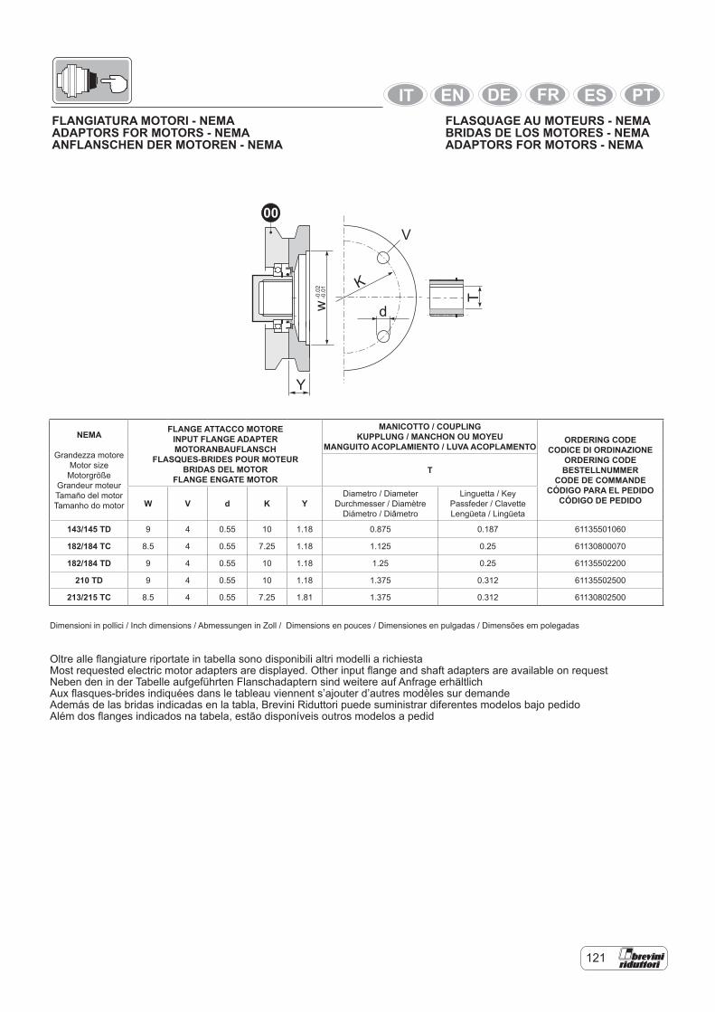
121
Y
w T
K
d
V
-0.0
2-0
.01
00
NEMA
Grandezza motoreMotor sizeMotorgröße
Grandeur moteurTamaño del motorTamanho do motor
FLANGE ATTACCO MOTOREINPUT FLANGE ADAPTERMOTORANBAUFLANSCH
FLASQUES-BRIDES POUR MOTEURBRIDAS DEL MOTOR
FLANGE ENGATE MOTOR
MANICOTTO / COUPLINGKUPPLUNG / MANCHON OU MOYEU
MANGUITO ACOPLAMIENTO / LUVA ACOPLAMENTOORDERING CODE
CODICE DI ORDINAZIONEORDERING CODEBESTELLNUMMER
CODE DE COMMANDECÓDIGO PARA EL PEDIDO
CÓDIGO DE PEDIDO
T
W V d K YDiametro / Diameter
Durchmesser / DiamètreDiámetro / Diâmetro
Linguetta / KeyPassfeder / ClavetteLengüeta / Lingüeta
143/145 TD 9 4 0.55 10 1.18 0.875 0.187 61135501060
182/184 TC 8.5 4 0.55 7.25 1.18 1.125 0.25 61130800070
182/184 TD 9 4 0.55 10 1.18 1.25 0.25 61135502200
210 TD 9 4 0.55 10 1.18 1.375 0.312 61135502500
213/215 TC 8.5 4 0.55 7.25 1.81 1.375 0.312 61130802500
Dimensioni in pollici / Inch dimensions / Abmessungen in Zoll / Dimensions en pouces / Dimensiones en pulgadas / Dimensões em polegadas
Oltre alle flangiature riportate in tabella sono disponibili altri modelli a richiestaMost requested electric motor adapters are displayed. Other input flange and shaft adapters are available on requestNeben den in der Tabelle aufgeführten Flanschadaptern sind weitere auf Anfrage erhältlichAux flasques-brides indiquées dans le tableau viennent s’ajouter d’autres modèles sur demandeAdemás de las bridas indicadas en la tabla, Brevini Riduttori puede suministrar diferentes modelos bajo pedidoAlém dos flanges indicados na tabela, estão disponíveis outros modelos a pedid
FLASQUAGE AU MOTEURS - NEMABRIDAS DE LOS MOTORES - NEMA ADAPTORS FOR MOTORS - NEMA
FLANGIATURA MOTORI - NEMAADAPTORS FOR MOTORS - NEMAANFLANSCHEN DER MOTOREN - NEMA
122
6. SUPPLY CONDITION
The gear units are painted externally with synthetic primer in blue “RAL 5010”, unless otherwise specified in the con-tract. The protection is suitable for with-standing normal industrial environments (also external) and can be finished with synthetic paints. If particular aggressive ambient conditions are foreseen, special painting is required.The worked external parts of the gear unit, such as the ends of the hollow and solid shafts, support tables, centerings, etc., must be protected with antioxidant oil (tectyl). The parts inside the gear unit casings are painted wiyh oil-proof paint and the kinematic mechanisms are pro-tected with antioxidant oil. Unless oth-erwise specified in the contract, all the gear units are supplied without lubri-cation: as specified by a special sticker placed on the unit for indicating its condi-tion.Brevini Riduttori S.p.A. products are packed and shipped in boxes or on pal-lets, as required.Unless otherwise specified in the con-tract, all Brevini products are packed with packing suitable for withstanding normal industrial environments.Every Brevini gear unit comes with a specific “Installation and Mainte-nance” manual. Manufacturer’s dec-laration and certificate of Conformity - UNI EM10204-2.1.
7. STORING CONDITIONSIf the product is to be stored for more than 2 months, carry out as follows:Protect the shafts and centerings with a film of grease and/or anticorrosiveprotection liquids.Completely fill the gear unit and possible multidisc brake with suitable oils.Store in a dry place with temperature of between -5 °C and +30 °C.Protect the packages from dirt, dust and damp.When storing for more than 6 months the rotating seals will loose efficiency.It is advisable to carry out a periodi-cal check,manually turning the inter-nal gears, turning the input shaft; with negative multidisc brake, release the brake, with hydraulic pump or similar (for brake release pressure see the chapter Brakes). Possible replacement of the gaskets on starting is advisable.
6. STATO DI FORNITURA
I riduttori sono verniciati esternamente con fondo epossidico sintetico blu “RAL 5010”, salvo di verse disposizioni con-trattuali. La protezione è idonea a resi-stere a normali ambienti industriali anche esterni e consente ulteriori finiture con vernici sintetiche.Nel caso si prevedano particolari condi-zioni ambientali aggressive, bisogna uti-lizzare delle verniciature speciali.Le parti esterne lavorate del riduttore come le estremità degli alberi cavi e non, piani di appoggio, centraggi ecc. vengo-no protetti con olio (tectyl) antiossidante. Le parti interne delle carcasse dei ridut-tori sono verniciate con vernice antiolio e i cinematismi sono protetti con olio an-tiossidante.Tutti i riduttori, salvo diverse indicazioni contrattuali, vengono forniti senza lu-brificazione: come indicato da un’appo-sita etichetta adesiva allegata al riduttore stesso per evidenziarne lo stato.I prodotti Brevini Riduttori S.p.A. vengo-no imballati e spediti, secondo i casi, in casse o su pallets. Tutti i prodotti Brevini, salvo diverse in-dicazioni contrattuali, vengono imballati con imballi idonei per resistere a nor-mali ambienti industriali.Ogni riduttore Brevini viene fornito con specifico manuale di “Installazio-ne e Manutenzione”. Dichiarazione del fabbricante e l’attestato di Conformità – UNI EM10204-2.1
7. CONDIZIONI DI STOCCAGGIONel caso occorra immagazzinare il pro-dotto per un periodo superiore ai 2 mesi attenersi a quanto segue:Proteggere gli alberi e i centraggi con pellicola di grasso e/o liquidi protettivi anticorrosione.Riempire totalmente il riduttore e l’even-tuale freno lamellare con oli adeguati.Immagazzinare in luogo asciutto e con temperatura compresa fra i -5 °C e +30 °C.Proteggere i colli dallo sporco, dalla pol-vere e dall’umidità.Per immagazzinamento prolungato oltre i 6 mesi decade l’efficienza per le tenute rotanti. Si consiglia un controllo periodico facendo ruotare gli ingranaggi interni a mano ruotando l’albero in entrata, in pre-senza di freno lamellare negativo, biso-gna sbloccare il freno, con pompa idrau-lica o similare (per pressione di apertura freno vedi capitolo freni). L’eventuale so-stituzione all’atto del l’avviamento delle guarnizioni è consigliata.
6. LIEFERBEDINGUNGEN
Die Außenseite der Getriebe ist mit Epo-xidharz blau “RAL 5010” lackiert, soweit vertraglich nicht anders vereinbart. Der Schutz ist für normale Industrieumge-bungen und Außenbereiche geeignet und gestattet zusätzliche Überlackierung mit Synthetiklacken. Bei Einsatz unter besonders aggressiven Umgebungs-bedingungen müssen Speziallacke ver-wendet werden.Die bearbeiteten Außenteile des Getrie-bes wie die Stümpfe der Hohlwellen und Wellen, Stützflächen, Zentrieransätze usw. werden mit einem Film oxidations-hemmenden Öls (Tectyl) geschützt. Die Innenteile der Getriebegehäuse werden mit schmierölfesten Lacken lackiert und die Getriebe sind durch oxidationshem-mendes Öl geschützt.Alle Getriebe, soweit vertraglich nicht anders vereinbart, werden ohne Schmieröl geliefert: ein Aufkleber auf dem Getriebe weist auf den Zustand desselben hin.Die Produkte Brevini Riduttori S.p.A. werden in Kisten oder auf Paletten gelie-fert und versandt.Alle Produkte Brevini, soweit vertraglich nicht anders vereinbart, werden in Ver-packungen geliefert, die für normale Industrieumgebungen ausreichend sind.Alle Getriebe Brevini sind mit einem spezifischen “Installations- und War-tungshandbuch”, mit Herstellererklä-rung und Konformitätsbescheinigung – UNI EM10204-2.1 versehen.
7. LAGERBEDINGUNGEN
Gehen Sie bei einer Lagerung des Pro-duktes für einen Zeitraum von mehr als 2 Monaten wie folgt vor:Schützen Sie die Wellen und die Zen-trieransätze mit einer dünnen Fettschicht und/oder Rostschutzmitteln.Füllen Sie das Getriebe und die eventu-elle Lamellenbremse ganz mit den emp-fohlenen Ölsorten.Lagern Sie die Getriebe an einem tro-ckenen Ort mit einer Temperatur von -5 °C bis +30 °C.Schützen Sie die Ware vor Schmutz, Staub und Feuchtigkeit. Bei Lagerung von mehr als 6 Monaten verlieren die Wellendichtungen ihre Wirksamkeit. Überprüfen Sie regelmä-ßig die Getriebe, indem Sie die Zahnrä-der von Hand mithilfe der Antriebswelle drehen; sollte eine Lamellenbremse ein-gebaut sein, muss die Bremse mit einer Hydraulikpumpe oder ähnlichem freige-setzt werden (für den Öffnungsdruck der Bremse siehe das Kapitel Bremsen). Bei der Inbetriebnahme sollte die Dichtung möglichst ersetzt werden.
124
8. INSTALLATIONThe gear units must be carefully installed by suitably trainedtechnical personnel.Preparation for operation must occur in compliance with all the technical speci-fications given in the dedicated Dimen-sional Drawing.All installation operations must comply with maximum safety regarding: 1) safety of operators and third parties2) correct operation of the reduction gear
unit3) operational safetyIn this respect, remember that:- Any arbitrary tampering with the gear
transmission and any accessories possibly originally arranged is strictly prohibited.
- All lifting and carrying operations must be carried out avoiding impacts on the shaft ends, using special lifting straps or the eye-bolts specially arranged, making sure that the lifting equipment is of adequate capacity.
- Welding work on the transmissions is absolutely prohibited.
- Any installation or maintenance work must be carried out with the unit stopped; therefore it is a good rule to prevent the possibility of accidental engaging of the driving power.
- Regarding the input side, often the electric or hydraulic motors are mount-ed with the well-known Brevini Univer-sal flange coupling system (See the chapter Universal Input). Remember that size “00” is normally used for motors of weights up to approx. 100 kg and max. torque 1000 Nm. With heavier motors, universal flange S00 (if available) or specific flange cou-plings can be used: contact the Brevi-ni Technical Commercial Service.
- With connections involving the use of revolving parts such as shafts, joints or pulleys with belts, adequate acci-dent-prevention guards must be pro-vided.
With flange-mounted gear units, it is ad-visable to comply with the following re-quirements:The structures to which they are fixed must be rigid, with perfectly flat machined unpainted support surfaces,normal with driven shaft, and with centerings to toler-ance H8.The contact surfaces must be duly and perfectly greased.
8. INSTALLAZIONEL’installazione dei riduttori deve esse-re realizzata con cura e professionalità impiegando personale adeguatamente istruito e tecnicamente preparato.La predisposizione al funzionamento deve avvenire rispettando tutte le indicazioni tecniche contenute nel Disegno Dimen-sionale dedicato.Tutte le operazioni di installazione deb-bono essere ispirate ai massimi livelli di sicurezza: 1) nei confronti dell’incolumità degli ope-
ratori e di terzi2) nei confronti di un corretto funziona-
mento del riduttore a ingranaggi3) nei confronti della sicurezza di eserci-
zioA questo proposito ricordiamo che:- E’ assolutamente vietata ogni mani-
polazione arbitraria al riduttore e a tutti gli accessori eventualmente pre-disposti all’origine.
- Tutte le operazioni di sollevamento e trasporto debbono essere effettuate evitando gli urti alle estremità d’albero ed utilizzando apposite cinghie di so-spensione o j golfari opportunamente predisposti. verificando che i mezzi di sollevamento siano dotati di sufficien-te portata.
- E’ assolutamente vietato eseguire la-vori di saldatura sui riduttori.
- Qualsiasi lavoro di installazione o manutenzione deve essere eseguito con il riduttore fermo. Quindi è buona norma assicurarsi che non possano verificarsi inserimenti non intenzionali della forza motrice.
- Per quanto riguarda il lato entrata, frequentemente, i motori elettrici od idraulici sono applicati con noto siste-ma di flangiatura Universale Brevini (Vedere il capitolo Entrata Universa-le). Si ricorda che la grandezza “00” viene normalmente impiegata per mo-tori di peso fino a 100 kg circa e cop-pia di 1000 Nm massimo. Nel caso di motori più pesanti si può ricorrere alla flangiatura universale S00, se dispo-nibile, oppure a flangiature specifiche contattando il Servizio Tecnico Com-merciale Brevini.
- Nel caso di collegamenti che implica-no l’impiego di parti rotanti come al-beri, giunti o pulegge con cinghie, è obbligatorio prevedere adeguate pro-tezioni antinfortunistiche.
Nel caso di riduttori montati a flangia si consiglia di osservare queste prescrizio-ni:Le strutture a cui vanno fissati devono essere rigide. con superfici di appoggio lavorate a macchina ben piane e prive di verniciatura, normali all’asse azionato, e con centraggi a tolleranza H8;Le superfici a contatto debbono essere preventivamente sgrassate in modo per-fetto.
8. INSTALLATIONDie Installation der Getriebe muss sor-gfältig und professionell durch technisch ausgebildete Fachkräfte ausgeführt wer-den.Die Vorbereitung zur Inbetriebnahme muss entsprechend den technischen Angaben der betreffenden Maßbilder er-folgen.Bei allen Installationsarbeiten sind im-mer die erforderlichen Sicherheitsmaß-nahmen zu ergreifen: 1) Sicherheit für Techniker und Dritte2) Sicherer Getriebelauf Zahnräder3) BetriebssicherheitDiesbezüglich wird daran erinnert, dass:- Jede willkürliche Veränderung der
Getriebe und des eventuell werkseitig vorgerüsteten Zubehörs ist streng-stens untersagt.
- Beim Anheben und Transport sind Stöße gegen die Wellenstümpfe zu vermeiden und Transportriemen oder die eigens vorgerüsteten Ösenschrau-ben zu verwenden. Kontrollieren Sie immer, dass das Hebezeug eine au-sreichende Tragfähigkeit aufweist.
- Es ist strengsten verboten, an den Getrieben Schweißarbeiten au-szuführen.
- Installations- und Wartungsarbeiten dürfen nur bei stehendem Getrie-be durchgeführt werden; es hat sich daher bewährt, sich zuvor immer zu vergewissern, dass der Antrieb nicht unvohergesehen anlaufen kann.
- Antriebsseitig werden die Elektro- oder Hydraulikmotoren oft mit dem bekannten Brevini - System der Flan-schverbindungen angebaut (siehe Kapitel “Universalantriebe”). Es wird daran erinnert, dass die Größe “00” gewöhnlich für Motoren bis zu einem Gewicht von ca. 100 kg und mit ma-ximalem Drehmoment von 1000 Nm eingesetzt wird. Bei schwereren Mo-toren können die Universalverbindung S00 (falls verfügbar) oder spezielle Flanschverbindungen verwendet wer-den; wenden Sie sich diesbezüglich an die technische Verkaufsberatung Brevini.
- Bei Verbindung mithilfe von rotieren-den Teilen wie Wellen, Kupplungen und Riemenscheiben ist die Installa-tion von Unfallschutzverkleidungen gesetzlich vorgeschrieben.
Bei angeflanschten Getrieben sollten die folgenden Vorschriften beachtet werden:Sie dürfen nur an starren Strukturen befestigt werden mit ebenen maschi-nenbearbeiteten unlackierten Auflage-flächen, gewöhnlich an der angetriebe-nen Achse und mit Zentrieransätzen mit Toleranz H8;Die Kontaktflächen müssen zuvor sor-gfältig entfettet werden.
126
The unit must be carefully aligned with the driven shaft, especially with gear units with female splined output shaft which, it must be remembered, do not take external loads.For fixing, use screws of class min. 10.9 with tightening at 75% yielding. During assembly, violent axial impacts must absolutely be avoided since they could damage the internal bearings. The control parts to be fitted on the cy-lindrical output shaft must be worked ac-cording to the specifications given in the chapter:”Output configurations”.
NB:With right-angle gear units, with male in-put shaft, on installation the input shaft may possibly not be in its ideal position.To avoid this situation:- with connections by means of joints
allowing alignment adjustment, mea-sure the existing misalignment,check the acceptable misalignment with the joint and if the value is greater, shim the motor to bring it within permissible play
- with connection by means of mechani-cal parts not allowing take-up of play, align the motor by shimming.
Deve essere curato l’allineamento tra il riduttore e l’albero da comandare, so-prattutto nel caso di riduttori con uscita femmina scanalata che, ricordiamo, non accettano carichi esterni;Per il fissaggio devono essere impiegate viti di classe minimo 10.9 con serraggio al 75% dello snervamento.Durante il montaggio debbono essere assolutamente evitati urti assiali violenti che potrebbero danneggiare i cuscinetti interniGli organi di comando da calettare sul-l’albero cilindrico in uscita devono essere lavorati come da indicazioni riportate nel capitolo: “Configurazioni uscite”.
NOTA:In caso di riduttori ortogonali, con albero maschio in ingresso, può verificarsi alla installazione che l’asse di ingresso sia deviato rispetto alla sua posizione idea-le.Per ovviare a questa situazione si con-siglia:- nel caso di collegamenti tramite giunti
in grado di re cuperare disallineamen-ti, di misurare il disallineamento esi-stente, di verificare il disallineamento accettabile dal giunto e nel caso in cui il valore sia maggiore di spessorare il motore per rientrare nei giochi ammis-sibili
- nel caso di collegamento tramite or-gani meccanici che non consentano recupero di giochi di procedere all’alli neamento del motore tramite spesso-ramenti.
Die Ausrichtung zwischen Getriebe und angetriebener Welle ist äußerst sorgfäl-tig vorzunehmen, besonders bei Hohl-wellen mit Keilnut, die, wie bekannt ist, keinen externen Belastungen ausgesetzt werden dürfen;Für die Befestigung sind Schrauben mit Mindestklasse 10.9 und Anziehmoment von 75% der Streckgrenze zu verwenden.Bei der Montage sind unbedingt heftige Stöße gegen die Achsen zu vermeiden, durch die die inneren Lager beschädigt werden können.Die Organe, die auf die zylindrische Ab-triebswelle aufgezogen werden, müssen entsprechend den Anweisungen im Ka-pitel:.
HINWEIS:Bei Winkelgetrieben mit Antriebswellen-stumpf kann es vorkommen, dass beim Einbau die Antriebswelle von der idealen Position abweicht.Gehen Sie in diesem Fall auf folgende Weise vor:- Messen Sie bei Verwendung von
Kupplungen, die in der Lage sind, die Fluchtungsabweichung auszuglei-chen, den bestehenden Fluchtungs-fehler und stellen Sie die für die Kupp-lung maximal zulässige Abweichung fest; falls der Wert höher sein sollte, setzen Sie beim Motor Unterlegschei-ben ein, bis das zulässige Spiel wie-der hergestellt ist.
- nel caso di collegamento tramite orBei Verbindung mithilfe von mechanischen Organen, die keine Spielwiederher-stellung erlauben, den Motor mithilfe von Unterlegscheiben ausrichten.
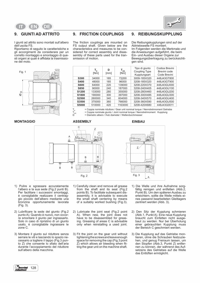
128
9. GIUNTI AD ATTRITO
I giunti ad attrito sono montati sull’albero dell’uscita FS.Riportiamo di seguito le caratteristiche e gli accorgimenti da considerare per un corretto montaggio e smontaggio di que-sti organi ai quali è affidata la trasmissio-ne del moto.
9. REIBUNGSKUPPLUNG
Die Reibungskupplungen sind auf der Abtriebswelle FS montiert.Im Folgenden werden die Merkmale und die Anweisungen aufgeführt, die beim Ein- und Ausbau dieser Organe zur Bewegungsübertragung zu berücksichti-gen sind.
D
TN [Nm]
D [mm]
TGN [Nm]
Tipo di giunto Coupling Type Kupplungsart
Codice Brevini Brevini code Code Brevini
S300 34000 185 72200 3009-185X320 448J43GT800S400 48000 185 96000 3208-185X320 448J43GT900S600 64000 220 139000 3208-220X370 448J43GU000S850 90000 240 187000 3208-240X405 448J43GU100S1200 133000 280 355000 3208-280X460 448J43GU200S1800 190000 300 397000 3208-300X485 448J43GU300S2500 260000 340 604000 3208-340X570 448J43GU400S3500 370000 360 766000 3208-360X590 448J43GU500S5000 510000 420 1163000 3208-420X680 448J43G0011
Fig. 1
MONTAGGIO
1) Pulire e sgrassare accuratamente l’albero e la sua sede (Fig.2 punti B). Per facilitare i successivi smontaggi, è consigliabile realizzare il centrag-gio piccolo dell’albero mediante una bronzina opportunamente lavorata (Fig. 3).
2) Lubrificare la sede del giunto (Fig.2 punto A). Quando è nuovo, non occor-re smontare il giunto per ingrassarlo. Solo in caso di ripristino di un giunto usato, è consigliabile ingrassare le zone C.
3) Montare il giunto sul riduttore senza serrare le viti e lasciando lo spazio ne-cessario a togliere il tappo (Fig.3 pun-to Z) che consente lo sfiato dell’aria durante l’accoppiamento del riduttore sull’albero della macchina.
BB
B
A
A
CZ
Z
B
Fig. 2
TN = Coppia nominale riduttore / Gear unit nominal torque / Nenndrehmoment Getriebe TGN = Coppia nominale giunto / Joint nominal torque / Nenndrehmoment Kupplung D = Diametro albero / Hub diameter / Wellendurchmesser
Fig. 3
9. FRICTION COUPLINGS
The friction couplings are mounted on FS output shaft. Given below are the characteristics and measures to be con-sidered for correct assembly and disas-sembly of these parts used for the tran-smission of motion.
1) Carefully clean and remove all grease from the shaft and its seat (Fig.2 points B). To facilitate subsequent dis-assembly, it is advisable to execute the small shaft centering by means of a suitably worked bushing (Fig.3).
2) Lubricate the joint seat (Fig.2 point A). When new, the joint does not have to be disassembled for greas-ing. Greasing of areas C is advisable only when reinstalling a used joint.
3) Fit the joint on the gear unit without tightening the screws and leave enough space for removing the cap (Fig.3 point Z) which allows air bleeding when fit-ting the gear unit on the machine shaft.
1) Die Welle und ihre Aufnahme sorg-fältig reinigen und entfetten (Abb.2, Punkt B). Um den späteren Ausbau zu erleichtern, sollte die Welle mittels ei-nes passend bearbeiteten Gleitlagers zentriert werden (Abb. 3).
2) Den Sitz der Kupplung schmieren (Abb.1, Punkt A). Eine neue Kupplung braucht zum Einfetten nicht ausge-baut zu werden. Nur bei Überholung einer gebrauchten Kupplung muss der Bereich C geschmiert werden.
3) Die Kupplung auf das Getriebe mon-tieren, ohne die Schrauben festzuzie-hen, und genug Freiraum lassen, um den Stopfen (Abb.3, Punkt Z) entfer-nen zu können, der während des Auf-setzens des Getriebes auf die Welle das Entlüften ermöglicht.
ASSEMBLY EINBAU
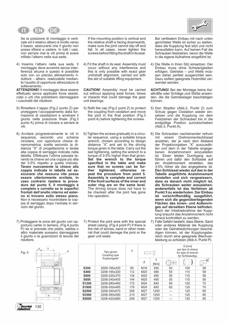
130
Se la posizione di montaggio è verti-cale ed il relativo albero è rivolto verso il basso, assicurarsi che il giunto non possa sfilarsi e cadere. In tutti i casi, non serrare mai le viti prima di avere infilato l’albero nella sua sede.
4) Inserire l’albero nella sua sede. Il montaggio deve avvenire senza inter-ferenza alcuna e questo è possibile solo con un preciso allineamento ri-duttore – albero. realizzabile median-te l’ausilio di opportune attrezzature di sollevamento.
ATTENZIONE! Il montaggio deve essere effettuato senza applicare forze assiali, colpi o urti che potrebbero danneggiare i cuscinetti del riduttore.
5) Rimettere il tappo (Fig.2 punto Z) per proteggere l’accoppiamento dalla for-mazione di ossidazioni e arretrare il giunto nella posizione finale (Fig.3 punto A) prima di iniziare a serrare le viti.
6) Avvitare progressivamente le viti in sequenza, secondo uno schema circolare, con opportuna chiave di-namometrica, scelta secondo la di-stanza “X” di progettazione e tarata alla coppia di serraggio indicata nella tabella. Effettuare l’ultima passata ta-rando la chiave ad una coppia più alta del 3-5% rispetto a quella indicata. Tarare nuovamente la chiave alla coppia indicata in tabella ed as-sicurarsi che nessuna vite possa essere ulteriormente avvitata, in caso contrario ripetere la proce-dura dal punto 5. Il montaggio è completo e corretto se le superfici frontali dell’anello interno ed ester-no si trovano sullo stesso piano. Non è necessario ricontrollare la cop-pia di serraggio dopo l’entrata in ser-vizio del giunto.
7) Proteggere la zona del giunto con op-portuno carter in lamiera, (Fig.4 punto P) se si prevede che pietre, sabbia o altro materiale possano danneggiare il giunto o le guarnizioni di tenuta del riduttore.
Tipo giuntoCoupling typeKupplungsart
YX [mm]
per tipo di chiave for type of wrench für Schlüsseltyp
d T [Nm]
S300 3009-185x320 85 M16 290 50 100 58S400 3208-185x320 112 M20 490 55 115 58S600 3208-220x370 134 M20 490 55 115 58S850 3208-240x405 144 M20 490 55 115 58
S1200 3208-280x460 172 M24 840 65 120 70S1800 3208-300x485 176 M24 840 65 120 70S2500 3208-340x570 206 M27 1250 — 125 85S3500 3208-360x590 210 M27 1250 — 125 85S5000 3208-420x680 246 M27 1250 — 125 85
P
d
YXFig. 4
If the mounting position is vertical and the relative shaft is facing downwards, make sure the joint cannot slip off and fall. In all cases, never tighten the screws before fitting the shaft in its seat.
4) Fit the shaft in its seat. Assembly must occur without any interference and this is only possible with exact gear unit/shaft alignment, carried out with the aid of suitable lifting equipment.
CAUTION! Assembly must be carried out without applying axial forces, blows or impacts that could damage the gear unit bearings.
5) Refit the cap (Fig.2 point Z) to protect the coupling from oxidation and move the joint in the final position (Fig.3 point A) before tightening the screws.
6) Tighten the screws gradually in a circu-lar sequence, using a suitable torque wrench, chosen according to design distance “X” and set to the driving torque given in the table. Carry out the last tightening, setting the wrench to a torque of 3-5% higher than that given. Set the wrench to the torque specified in the table and make sure that no screws can be fur-ther tightened, otherwise re-peat the procedure from point 5. Assembly is complete and correct if the front surfaces of the inner and outer ring are on the same level. The driving torque does not have to be checked after the joint has gone into operation.
7) Protect the joint area with the special sheet casing, (Fig.4 point P) if there is the risk of stones, sand or other mate-rial that could damage the joint or the gear unit seals.
Bei vertikalem Einbau mit nach unten gerichteter Welle ist sicher zu stellen, dass die Kupplung fest sitzt und nicht herausfallen kann. Auf keinen Fall die Schrauben festziehen, bevor die Welle in die eigene Aufnahme eingeführt ist.
4) Die Welle in ihren Sitz einsetzen. Der Einbau muss ohne Schwierigkeiten erfolgen, Getriebe – und Welle müs-sen daher perfekt ausgerichtet sein. Dazu sollten geeignete Hubmittel ver-wendet werden.
ACHTUNG! Bei der Montage keine Axi-alkräfte oder Schläge und Stöße anwen-den, die die Getriebelager beschädigen können.
5) Den Stopfen (Abb.2, Punkt Z) zum Schutz gegen Oxidation wieder ein-setzen und die Kupplung vor dem Festziehen der Schrauben bis in die endgültige Position zurückschieben (Abb.3, Punkt A).
6) Die Schrauben nacheinander reihum mit einem Drehmomentschlüssel anziehen, der je nach dem Abstand der Projektvorgaben “X” auszuwäh-len und dem in der Tabelle angege-benen Anziehmoment einzustellen ist. Einen letzten Durchgang aus-führen und dafür den Schlüssel auf ein Anziehmoment einstellen, das 3-5% höher als das angegebene ist. Den Schlüssel wieder auf das in der Tabelle angeführte Anziehmoment einstellen und sich vergewissern, dass es danach nicht möglich ist, die Schrauben weiter anzuziehen; anderenfalls ist das Verfahren ab Punkt 5 zu wiederholen. Der Einbau ist vorschriftsmäßig ausgeführt, wenn sich die gegenüberliegenden Flächen des Innen- und Außenrin-ges auf derselben Ebene befinden. Nach der Inbetriebnahme der Kupp-lung braucht das Anziehmoment nicht erneut kontrolliert zu werden.
7) Falls Gefahr besteht, dass Steine, Sand oder anderes Material die Kupplung oder die Getriebedichtungen beschä-digen können, ist der Kupplungsbe-reich durch eine geeignete Blechver-kleidung zu schützen (Abb.4, Punkt P).
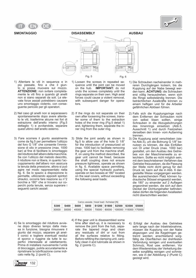
132
SMONTAGGIO
1) Allentare le viti in sequenza e in più passate, fino a che il giun-to si possa muovere sul mozzo. ATTENZIONE: non svitare completa-mente le viti fino a quando gli anelli non si siano separati da soli. Le ele-vate forze assiali potrebbero causare uno smontaggio violento, con conse-guente pericolo per gli operatori.
2) Nel caso gli anelli non si separassero spontaneamente dopo avere allenta-to le viti, trasferirne alcune nei fori di estrazione dell’anello interno (Fig.5 dettaglio 1) e avvitandole, separare quest’ultimo dall’anello esterno.
3) Fare scorrere il giunto assialmente come da fig.5 per permettere l’utilizzo del foro G 1/8” che consente l’immis-sione di olio in pressione (max. 1000 bar) al fine di facilitare lo smontaggio del riduttore dall’albero della macchina. Se con l’utilizzo del metodo descritto, il riduttore non si libera, in quanto l’ac-coppiamento dell’albero non assicura la tenuta della pressione, allora si può agire nel modo rappresentato nella fig. 6. Se lo spazio a disposizione lo permette, utilizzando appositi spintori idraulici, occorre fare reazione su n°2 borchie a 180° che si trovano sui co-perchi porta tenute, senza superare i seguenti carichi assiali:
4) Se lo smontaggio del riduttore avvie-ne dopo diverso tempo dalla mes-sa in funzione, bisogna rimuovere il giunto dal mozzo, separare gli anel-li conici e togliere eventuali residui di sporco o ruggine da tutte le su-perfici interessate al calettamento. Prima di installare nuovamente l’unità di bloccaggio, pulirla accuratamente e ripristinare la lubrificazione come indi-cato nella fig. 2 (punti C).
Fig. 5 Fig. 6
1
1) Loosen the screws in repeated se-quence until the joint can be moved on the hub. IMPORTANT: do not undo the screws completely until the rings separate on their own. High axial forces could cause a violent removal, with subsequent danger for opera-tors.
2) If the rings do not separate on their own after loosening the screws, trans-fer some of them to the extraction holes of the inner ring (Fig.5 detail 1) and, tightening them, separate the in-ner ring from the outer ring.
3) Slide the joint axially as shown in fig.5 to allow use of the hole G 1/8” for the introduction of pressurized oil (max. 1000 bar) to facilitate removing the gear unit from the machine shaft. If, on using the method described, the gear unit cannot be freed, because the shaft coupling does not ensure pressure tightness, operate as shown in fig. 6. Available space permitting, using the special hydraulic pushers, operate on two bosses at 180° located on the seal covers, without exceeding the following axial loads:
4) If the gear unit is disassembled some time after start-up, it is necessary to remove the joint from the hub, sepa-rate the tapered rings and clean any residuals of dirt or rust from all the surfaces relative to fitting. Before refitting the clamping unit, care-fully clean it and lubricate as shown in fig. 2 (points C).
DISASSEMBLY AUSBAU
1) Die Schrauben nacheinander in meh-reren Durchgängen lockern, bis die Kupplung auf der Nabe bewegt wer-den kann. ACHTUNG: die Schrauben erst völlig herausdrehen, wenn sich die Ringe selbstständig trennen. Die beträchtlichen Axialkräfte können zu einem heftigen und für die Arbeiter gefährlichen Ablösen führen.
2) Falls sich die Kupplungsringe nach dem Entfernen der Schrauben nicht von selbst lösen sollten, einige Schrauben in die Abzugsbohrungen des Innenrings einsetzen (Abb.5, Ausschnitt 1) und durch Festziehen derselben den Innen- vom Außenring trennen.
3) Die Kupplung axial verschieben (sie-he Abb.5), um die Bohrung G 1/8” be-nutzen zu können, die das Einfüllen von Öl unter Druck (max. 1000 bar) gestattet, um den Ausbau des Getrie-bes von der Maschinenwelle zu er-leichtern. Sollte es nicht möglich sein, mit dem beschriebenen Verfahren das Getriebe freizusetzen, da die Passung der Welle nicht dicht genug für den Druck ist, kann auf die in Abb. 6 dar-gestellte Weise vorgegangen werden. Bei ausreichendem Platz können hy-draulische Stössel eingesetzt werden, die 180° zu einander auf 2 Auflagen angeordnet werden, die sich auf dem Deckel der Dichtungshalter befinden; dabei dürfen die folgenden Axiallasten nicht überschritten werden:
4) Erfolgt der Ausbau des Getriebes sehr lange nach der Inbetriebnahme, müssen die Kupplung von der Nabe abgezogen und die Kegelringen ge-trennt werden; anschließend sorg-fältig die Oberflächen der drehfesten Verbindung reinigen und eventuellen Schmutz, Rost usw. entfernen. Vor dem Wiedereinbau der Verkeilung die-selbe sorgfältig reinigen und schmie-ren, wie in der Abbildung 2 (Punkt C) gezeigt wird.
Carico assiale / Axial load / Achslast [N]
S300 S400 S600 S850 S1200 S1800 S2500 S3500 S500030000 30000 45000 50000 70000 80000 100000 115000 170000
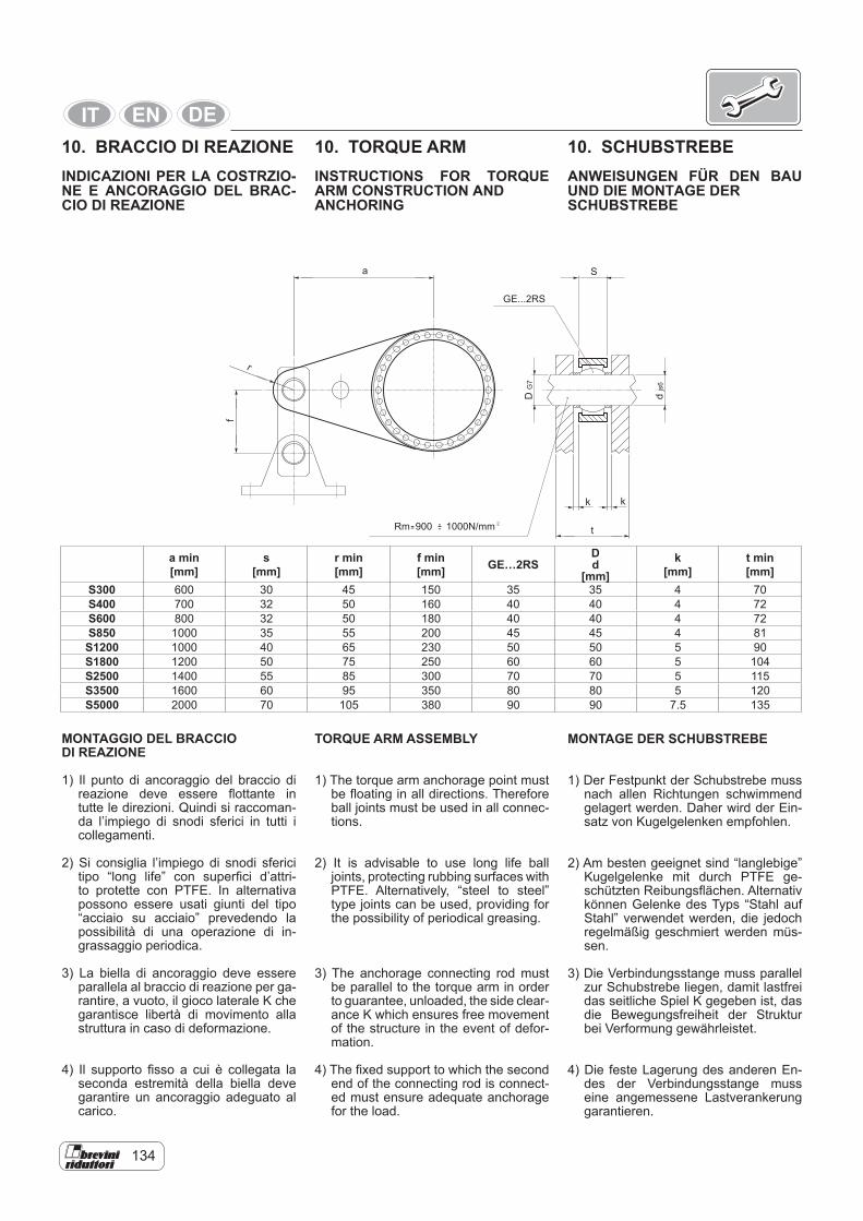
134
djs
6
DG
7
k
t
S
GE...2RS
a
r
f
k
Rm 900 1000N/mm-- 2
a min[mm]
s[mm]
r min[mm]
f min[mm] GE…2RS
Dd
[mm]k
[mm]t min[mm]
S300 600 30 45 150 35 35 4 70S400 700 32 50 160 40 40 4 72S600 800 32 50 180 40 40 4 72S850 1000 35 55 200 45 45 4 81S1200 1000 40 65 230 50 50 5 90S1800 1200 50 75 250 60 60 5 104S2500 1400 55 85 300 70 70 5 115S3500 1600 60 95 350 80 80 5 120S5000 2000 70 105 380 90 90 7.5 135
MONTAGGIO DEL BRACCIO DI REAZIONE
1) Il punto di ancoraggio del braccio di reazione deve essere flottante in tutte le direzioni. Quindi si raccoman-da l’impiego di snodi sferici in tutti i collegamenti.
2) Si consiglia l’impiego di snodi sferici tipo “long life” con superfici d’attri-to protette con PTFE. In alternativa possono essere usati giunti del tipo “acciaio su acciaio” prevedendo la possibilità di una operazione di in-grassaggio periodica.
3) La biella di ancoraggio deve essere parallela al braccio di reazione per ga-rantire, a vuoto, il gioco laterale K che garantisce libertà di movimento alla struttura in caso di deformazione.
4) Il supporto fisso a cui è collegata la seconda estremità della biella deve garantire un ancoraggio adeguato al carico.
TORQUE ARM ASSEMBLY
1) The torque arm anchorage point must be floating in all directions. Therefore ball joints must be used in all connec-tions.
2) It is advisable to use long life ball joints, protecting rubbing surfaces with PTFE. Alternatively, “steel to steel” type joints can be used, providing for the possibility of periodical greasing.
3) The anchorage connecting rod must be parallel to the torque arm in order to guarantee, unloaded, the side clear-ance K which ensures free movement of the structure in the event of defor-mation.
4) The fixed support to which the second end of the connecting rod is connect-ed must ensure adequate anchorage for the load.
MONTAGE DER SCHUBSTREBE
1) Der Festpunkt der Schubstrebe muss nach allen Richtungen schwimmend gelagert werden. Daher wird der Ein-satz von Kugelgelenken empfohlen.
2) Am besten geeignet sind “langlebige” Kugelgelenke mit durch PTFE ge-schützten Reibungsflächen. Alternativ können Gelenke des Typs “Stahl auf Stahl” verwendet werden, die jedoch regelmäßig geschmiert werden müs-sen.
3) Die Verbindungsstange muss parallel zur Schubstrebe liegen, damit lastfrei das seitliche Spiel K gegeben ist, das die Bewegungsfreiheit der Struktur bei Verformung gewährleistet.
4) Die feste Lagerung des anderen En-des der Verbindungsstange muss eine angemessene Lastverankerung garantieren.
10. BRACCIO DI REAZIONEINDICAZIONI PER LA COSTRZIO-NE E ANCORAGGIO DEL BRAC-CIO DI REAZIONE
10. SCHUBSTREBEANWEISUNGEN FÜR DEN BAU UND DIE MONTAGE DERSCHUBSTREBE
10. TORQUE ARMINSTRUCTIONS FOR TORQUE ARM CONSTRUCTION ANDANCHORING
136
5) Il braccio di reazione e la relativa biel-la possono avere soluzioni di progetto diverse da quelle proposte, ma è tas-sativo rispettare i seguenti accorgi-menti:• Il braccio di reazione deve essere
perfettamente dritto• Se si prevedono pezzi saldati, oc-
corre sabbiare, normalizzare e cor-reggere di macchina utensile even-tuali deformazioni
• La superficie di contatto del braccio di reazione in corrispondenza della flangiatura al riduttore, deve essere perfettamente piana
• Prima di collegare il braccio di rea-zione al riduttore, eliminare accura-tamente ogni traccia di grasso dalle superfici a contatto.
ATTENZIONE Non eseguire alcun lavo-ro di saldatura che coinvolga il riduttore nemmeno come messa a terra!
6) Usare sempre la chiave dinamometri-ca per serrare le viti di collegamento.
7) Il disegno fornisce solo un esempio indicativo, poiché, la configurazione corretta, dipende dal senso di rotazio-ne del riduttore. Infatti, durante il lavo-ro, è consigliabile che la biella risulti in trazione e non in compressione. Quin-di può essere conveniente il montag-gio dal lato opposto, relativamente alla raffigurazione. In caso di necessità, a causa di ingombri specifici, la biella può essere montata verso l’alto.
8) Quando si esegue un montaggio tra-mite giunto calettatore ad attrito e braccio di reazione, occorre ricordare che i pesi del riduttore, del braccio di reazione e di tutti gli elementi ad essi collegati, inducono carichi e momenti ribaltanti che vengono sopportati dai cuscinetti del portasatelliti dello stadio d’uscita. Quindi la posizione relati-va di tutte le masse che concorrono alla trasmissione della potenza deve essere valutata in sede di progetto al fine di rendere minimo il valore del-le risultanti su detti cuscinetti. Per le stesse ragioni è chiaro che si deve limitare al massimo il peso dei com-ponenti collegati al riduttore, valutan-do accuratamente gli spessori delle strutture effettivamente necessarie a reggere gli sforzi e decentrando tutti gli elementi che non sono fun-zionali alla trasmissione di potenza. Una progettazione impropria, può ac-corciare la vita dei riduttori causando cedimenti prematuri dei cuscinetti e degli ingranaggi a causa di eventuali eccessive deformazioni elastiche de-gli stadi e determinare la possibilità di slittamento e grippaggio del giunto ad attrito.
5) The torque arm and relevant con-necting rod can have different design solutions to those proposed, but the following arrangements must be re-spected.• The torque arm must be perfectly
straight• If welded parts are provided for,
any deformations must be sanded, normalized and machine tool cor-rected
• The contact area of the torque arm at the flanging with the reduction unit must be perfectly flat
• Before connecting the torque arm to the gear unit, carefully remove all traces of grease from the contact surfaces.
WARNING Do not carry out any welding work involving the gear unit, even as an earthing!
6) Always use a torque wrench for tight-ening the connection screws.
7) The drawing is only by way of exam-ple, since the correct configuration de-pends on the gear unit rotation direc-tion. In fact, during work it is advisable for the connecting rod to be in trac-tion and not compression. Therefore mounting on the opposite side with respect to that represented may be convenient. If necessary, due to spe-cific encumbrance the connecting rod can be assembled upwards.
8) When carrying out an assembly by means of friction coupling and torque arm, remember that the weights of the gear unit, the torque arm and all the elements connected to them, bring about loads and tipping mo-ments that are supported by the out-put stage planetary carrier bearings. Therefore the relative position of all the masses involved in transmitting power must be appraised in the de-sign phase, in order to minimize the resultant value on the bearings. Like-wise, the weight of the components connected to the gear unit must be limited, carefully appraising the hick-nesses of the structures actually nec-essary for supporting the stresses, and decentralizing all the elements not involved in power transmission. An incorrect design can shorten the life of the bearing and gears due to possible excessive elastic deforma-tion of the stages and determine the possibility of slipping and seizing of the friction coupling.
5) Die Schubstrebe und die Verbindungs-stange können andere rojektlösungen als die beschriebene aufweisen, müs-sen jedoch in jedem Fall die folgen-den Bedingungen einhalten• Die Schubstrebe muss perfekt ge-
rade sein• Bei Schweißstellen müssen even-
tuelle Verformungen sandgestrahlt, normalisiert und mit Werkzeugma-schinen nachgearbeitet werden
• Die Kontaktfläche der Schubstrebe auf Höhe der Flanschverbindung mit dem Getriebe muss perfekt eben sein
• Vor der Verbindung der Schubstre-be mit dem Getriebe sorgfältig alle Fettrückstände von den Kontaktflä-chen entfernen.
ACHTUNG Keine Schweißarbeiten am Getriebe ausführen, nicht einmal für die Erdung!
6) Verwenden Sie beim Anziehen der Schrauben immer den Drehmoment-schlüssel.
7) Die Zeichnung stellt nur ein Beispiel vor, da die genaue Konfiguration im-mer von der Drehrichtung des Ge-triebes abhängt. Während der Arbeit sollte die Schubstange immer unter Zug- und nicht unter Schubbedin-gungen stehen. Es kann daher ange-bracht sein, die Montage in Bezug auf die Abbildung auf der anderen Seite vorzunehmen. Bei Bedarf infolge besonderer Abmessungen kann die Schubstrebe in nach oben gerichteter Stellung montiert werden.
8) Bei einem Einbau mittels Reibungs-kupplung und Schubstrebe darf nicht vergessen werden, dass das Gewicht des Getriebes, der Schubstrebe und aller damit verbundenen Bauteile Las-ten und Kippmomente verursachen, die auf den Lagern des Planetenrad-trägers der Abtriebsstufe lasten. Die Anordnung aller Gewichte, die an der Leistungsübertragung beteiligt sind, muss daher bei der Planung genau bewertet werden, um die Aus-wirkungen auf die genannten Lager zu minimieren. Aus denselben Grün-den muss das Gewicht der mit dem Getriebe verbundenen Bauteile so weit wie möglich begrenzt werden; dabei ist die Stärke der Strukturen, die effektiv erforderlich ist, um den anfallenden Kräften standzuhalten, zu berücksichtigen und sind alle Elemen-te, die für die Leistungsübertragung nicht unerlässlich sind, zu verlagern. Eine schlechte Planung kann die Le-bensdauer der Getriebe verkürzen, zu inem frühzeitigen Nachgeben der La-ger und Zahnräder führen infolge von ußergewöhnlichen Verformungen der Stufen und das Rutschen und Fest-fressen der Reibungskupplung verur-sachen.
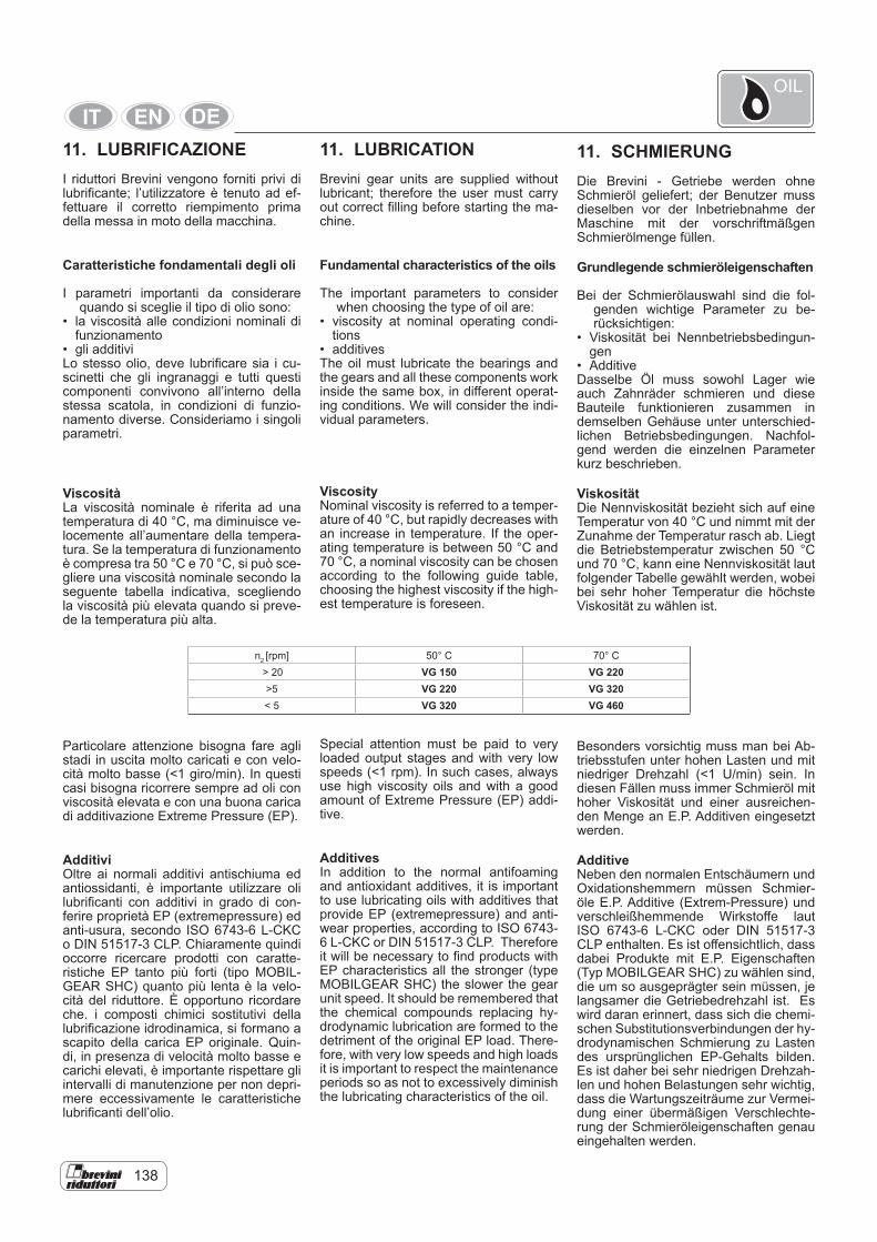
138
11. LUBRIFICAZIONEI riduttori Brevini vengono forniti privi di lubrificante; l’utilizzatore è tenuto ad ef-fettuare il corretto riempimento prima della messa in moto della macchina.
Caratteristiche fondamentali degli oli
I parametri importanti da considerare quando si sceglie il tipo di olio sono:
• la viscosità alle condizioni nominali di funzionamento
• gli additiviLo stesso olio, deve lubrificare sia i cu-scinetti che gli ingranaggi e tutti questi componenti convivono all’interno della stessa scatola, in condizioni di funzio-namento diverse. Consideriamo i singoli parametri.
ViscositàLa viscosità nominale è riferita ad una temperatura di 40 °C, ma diminuisce ve-locemente all’aumentare della tempera-tura. Se la temperatura di funzionamento è compresa tra 50 °C e 70 °C, si può sce-gliere una viscosità nominale secondo la seguente tabella indicativa, scegliendo la viscosità più elevata quando si preve-de la temperatura più alta.
Particolare attenzione bisogna fare agli stadi in uscita molto caricati e con velo-cità molto basse (<1 giro/min). In questi casi bisogna ricorrere sempre ad oli con viscosità elevata e con una buona carica di additivazione Extreme Pressure (EP).
AdditiviOltre ai normali additivi antischiuma ed antiossidanti, è importante utilizzare oli lubrificanti con additivi in grado di con-ferire proprietà EP (extremepressure) ed anti-usura, secondo ISO 6743-6 L-CKC o DIN 51517-3 CLP. Chiaramente quindi occorre ricercare prodotti con caratte-ristiche EP tanto più forti (tipo MOBIL-GEAR SHC) quanto più lenta è la velo-cità del riduttore. È opportuno ricordare che. i composti chimici sostitutivi della lubrificazione idrodinamica, si formano a scapito della carica EP originale. Quin-di, in presenza di velocità molto basse e carichi elevati, è importante rispettare gli intervalli di manutenzione per non depri-mere eccessivamente le caratteristiche lubrificanti dell’olio.
11. LUBRICATION Brevini gear units are supplied without lubricant; therefore the user must carry out correct filling before starting the ma-chine.
Fundamental characteristics of the oils
The important parameters to consider when choosing the type of oil are:
• viscosity at nominal operating condi-tions
• additives The oil must lubricate the bearings and the gears and all these components work inside the same box, in different operat-ing conditions. We will consider the indi-vidual parameters.
Viscosity Nominal viscosity is referred to a temper-ature of 40 °C, but rapidly decreases with an increase in temperature. If the oper-ating temperature is between 50 °C and 70 °C, a nominal viscosity can be chosen according to the following guide table, choosing the highest viscosity if the high-est temperature is foreseen.
Special attention must be paid to very loaded output stages and with very low speeds (<1 rpm). In such cases, always use high viscosity oils and with a good amount of Extreme Pressure (EP) addi-tive.
Additives In addition to the normal antifoaming and antioxidant additives, it is important to use lubricating oils with additives that provide EP (extremepressure) and anti-wear properties, according to ISO 6743-6 L-CKC or DIN 51517-3 CLP. Therefore it will be necessary to find products with EP characteristics all the stronger (type MOBILGEAR SHC) the slower the gear unit speed. It should be remembered that the chemical compounds replacing hy-drodynamic lubrication are formed to the detriment of the original EP load. There-fore, with very low speeds and high loads it is important to respect the maintenance periods so as not to excessively diminish the lubricating characteristics of the oil.
11. SCHMIERUNGDie Brevini - Getriebe werden ohne Schmieröl geliefert; der Benutzer muss dieselben vor der Inbetriebnahme der Maschine mit der vorschriftmäßgen Schmierölmenge füllen.
Grundlegende schmieröleigenschaften
Bei der Schmierölauswahl sind die fol-genden wichtige Parameter zu be-rücksichtigen:
• Viskosität bei Nennbetriebsbedingun-gen
• Additive Dasselbe Öl muss sowohl Lager wie auch Zahnräder schmieren und diese Bauteile funktionieren zusammen in demselben Gehäuse unter unterschied-lichen Betriebsbedingungen. Nachfol-gend werden die einzelnen Parameter kurz beschrieben.
Viskosität Die Nennviskosität bezieht sich auf eine Temperatur von 40 °C und nimmt mit der Zunahme der Temperatur rasch ab. Liegt die Betriebstemperatur zwischen 50 °C und 70 °C, kann eine Nennviskosität laut folgender Tabelle gewählt werden, wobei bei sehr hoher Temperatur die höchste Viskosität zu wählen ist.
Besonders vorsichtig muss man bei Ab-triebsstufen unter hohen Lasten und mit niedriger Drehzahl (<1 U/min) sein. In diesen Fällen muss immer Schmieröl mit hoher Viskosität und einer ausreichen-den Menge an E.P. Additiven eingesetzt werden.
Additive Neben den normalen Entschäumern und Oxidationshemmern müssen Schmier-öle E.P. Additive (Extrem-Pressure) und verschleißhemmende Wirkstoffe laut ISO 6743-6 L-CKC oder DIN 51517-3 CLP enthalten. Es ist offensichtlich, dass dabei Produkte mit E.P. Eigenschaften (Typ MOBILGEAR SHC) zu wählen sind, die um so ausgeprägter sein müssen, je langsamer die Getriebedrehzahl ist. Es wird daran erinnert, dass sich die chemi-schen Substitutionsverbindungen der hy-drodynamischen Schmierung zu Lasten des ursprünglichen EP-Gehalts bilden. Es ist daher bei sehr niedrigen Drehzah-len und hohen Belastungen sehr wichtig, dass die Wartungszeiträume zur Vermei-dung einer übermäßigen Verschlechte-rung der Schmieröleigenschaften genau eingehalten werden.
n2 [rpm] 50° C 70° C
> 20 VG 150 VG 220>5 VG 220 VG 320< 5 VG 320 VG 460
OIL
140
Tipi di oliGli oli disponibili appartengono general-mente a tre grandi famiglie.1) Oli minerali2) Oli sintetici Poli-Alfa-Olefine3) Oli sintetici Poli-GlicoleLa scelta più appropriata è generalmente
legata alle condizioni di impiego.
I riduttori non particolarmente caricati e con un ciclo di impiego discontinuo sen-za escursioni termiche importanti, posso-no certamente essere lubrificati con olio minerale.Nei casi di impiego gravoso, quando i ri-duttori saranno prevedibilmente caricati molto ed in modo continuativo, con con-seguente prevedibile innalzamento della temperatura, è bene utilizzare lubrificanti sintetici tipo polialfaolefine (PAO).Gli oli di tipo poliglicole (PG) sono da uti-lizzare strettamente nel caso di applica-zioni con forti strisciamenti fra i contatti, ad esempio nelle viti senza fine. Debbo-no essere impiegati con grande atten-zione poiché non sono compatibili con gli altri oli e sono invece completamente miscibili con l’acqua. Questo fenomeno è particolarmente pericoloso poiché non si nota, ma deprime velocemente le carat-teristiche lubrificanti dell’olio.Oltre a questi già menzionati, ricordiamo che esistono gli oli idraulici e gli oli per l’industria alimentare.I primi vengono usati per il comando dei freni negativi. Per una maggiore tutela dell’ambiente sottolineiamo l’esistenza di alcuni tipi biodegradabili.I secondi trovano specifico impiego nel-l’industria alimentare in quanto sono pro-dotti speciali non nocivi alla salute.Vari produttori forniscono oli appartenen-ti a tutte le famiglie con caratteristiche molto simili. Più avanti proponiamo una tabella comparativa tra le marche più note.
Types of oils The oils available generally belong to three big families. 1) Mineral oils 2) Poly-Alpha-Olefin synthetic oils 3) Poly-Glycol synthetic oils The most suitable choice is generally tied
to the conditions of use.
Gear units that are not particularly load-ed and with a discontinuous operating cycle, without considerable temperature ranges, can certainly be lubricated with mineral oil. In cases of heavy use, when the gear units are very loaded and in a continuous way, with resultant temperature increase, it is best to use polyalphaolefin synthetic lubricants (PAO). Polyglycol oils (PG) are to be used strict-ly in the case of applications with heavy sliding between contacts, e.g. in worms. They must be employed with great care since they are not compatible with the other oils but are completely mixable with water. This phenomenon is particularly dangerous, since it is not noticed, but rapidly diminishes the lubricating charac-teristics of the oil. In addition to the above, there are also hydraulic oils and oils for the food indus-try. The former are used for the command of negative brakes. For better environmen-tal protection there are several biode-gradable types. The latter have a specific use in the food industry since they are special products that are not harmful to the health. Various producers supply oils belonging to all the families with very similar char-acteristics. A comparison table of the best known brands is given later on.
Schmierölsorten Die verfügbaren Ölsorten gehören allge-mein zu drei großen Familien 1) Mineralöle 2) Synthetische Poly-Alpha-Olefin-Öle 3) Synthetische Polyglykolöle Die Auswahl hängt im Allgemeinen von
den Einsatzbedingungen ab.
Getriebe, die nicht im Dauerbetrieb lau-fen und keinen großen Belastungen und großen Temperaturschwankungen aus-gesetzt sind, können problemlos mit Mi-neralölen geschmiert werden. Bei Einsatz unter erschwerten Bedin-gungen, bei denen die Getriebe voraus-sichtlich hohen Lasten im Dauerbetrieb mit der entsprechenden voraussehbaren Temperaturerhöhung ausgesetzt sind, ist es angebracht, synthetische Poly-Alpha-Olefin-Öle (PAO) zu verwenden. Die Poly-Glykolöle (PG) werden in An-wendungen benutzt, in denen starke Gleitreibungen zwischen den Kontaktflä-chen auftreten, wie z. B. in Schnecken. Bei ihrer Anwendung ist sehr sorgfältig vorzugehen, da sie mit anderen Schmier-ölen unverträglich, aber voll mit Wasser vermischbar sind. Das ist besonders ge-fährlich, weil es unbemerkt erfolgt und sehr schnell die Schmiereigenschaften des Öls verschlechtert. Neben den erwähnten Ölen gibt es noch Hydrauliköl und Öle für die Lebensmittel-industrie. Die ersteren werden auf Negativbrem-sen eingesetzt. Zum Umweltschutz wei-sen wir auf einige biologisch abbaubare Ölsorten hin. Die zweiten werden von der Lebensmit-telindustrie verwendet, da sie nicht ge-sundheitsschädlich sind. Einige Hersteller liefern Schmieröle, die allen Familien mit sehr ähnlichen Merk-malen angehören. An anderer Stelle finden Sie eine Vergleichstabelle der be-kanntesten Ölmarken.
OIL
142
ContaminazioneDurante il normale funzionamento, a causa del rodaggio delle superfici, è ine-vitabile che si trasferiscano nell’olio delle microparticelle metalliche. Questa con-taminazione, può accorciare la vita dei cuscinetti, mandando in avaria prematu-ra il riduttore. Per limitare e controllare il fenomeno, senza ricorrere a frequenti e costosi cambi d’olio, occorre prevedere l’impiego di un opportuno sistema ausi-liario di circolazione dell’olio.Con questo sistema, si ottiene il doppio vantaggio di controllare il livello di conta-minazione con l’impiego di appositi filtri e di stabilizzare la temperatura di fun-zionamento al livello più adeguato per garantire la viscosità voluta. Infatti, può succedere che la capacità termica spe-cifica del riduttore è insufficiente a ga-rantire un livello di temperatura di funzio-namento corretto e stabile. Vedremo più avanti i sistemi ausiliari disponibili presso la Brevini Riduttori.
Per problemi di lubrificazione di riduttori destinati a impieghi particolari sia per la tipologia costruttiva, sia per i parametri di funzionamento, è consigliabile contattare il servizio Tecnico-Commerciale Brevini.A questo proposito ricordiamo che la Brevini Riduttori si avvale di un accordo tecnico con la Exxon Mobil in base al quale si può avere sia una consulenza preventiva mirata all’applicazione, sia il monitoraggio di applicazioni lubrificate con prodotti MOBIL.
Contamination During normal operation, due to running-in of the surfaces, metallic microparti-cles will inevitably form in the oil. This contamination can shorten the life of the bearings, resulting in early breakdown of the gear unit. To limit and control this phenomenon, without resorting to fre-quent and costly oil changes, a suitable auxiliary oil circulating system must be provided. This system offers the dual advantage of controlling the level of contamination with the use of special filters and sta-bilizing the operating temperature at a level more suitable for guaranteeing the required viscosity. In fact, the specific thermal capacity of the gear unit is some-times insufficient to ensure a correct and stable operating temperature level. The auxiliary systems available from Brevini Riduttori will be described later on.
For lubrication problems with gear units intended for particular uses, for construc-tion type and operating parameters, it is advisable to contact the Brevini Techni-cal Commercial service. In this respect, Brevini Riduttori has a technical agreement with Exxon Mobil for having preventive advice for the specific application, and the monitoring of appli-cations lubricated with MOBIL products.
Verschmutzung Während des normalen Betriebs entste-hen durch den Abrieb der Oberflächen Mikrometallpartikel im Öl. Diese Ver-schmutzung kann die Lebensdauer der Lager verkürzen und zu einem Ausfall des Getriebes führen. Zur Einschrän-kung dieser Erscheinung ohne häufigen und kostspieligen Ölwechsel ist der Ein-bau einer zusätzlichen Filteranlage des Schmieröls empfehlenswert. Diese Anlage bietet den doppelten Vor-teil, einserseits den Grad der Ölver-schmutzung zu reduzieren und ande-rerseits die Betriebstemperatur auf einer für die gewünschte Viskosität geigneten Temperaturstufe zu stabilisieren. Es kann mitunter der Fall eintreten, dass die spe-zifische Wärmeleistung des Getriebes nicht ausreicht, eine korrekte und stabile Stufe der Betriebstemperatur zu gewähr-leisten. An anderer Stelle werden die bei Brevini Riduttori verfügbaren Hilfssyste-me beschrieben.
Wenden Sie sich bei Schmierproblemen von Getrieben, die sowohl bauseitig wie auch aufgrund der Betriebsparameter für besondere Anwendungen vorgesehen sind, direkt an die technische Verkaufs-beratung Brevini. In diesem Zusammenhang dürfen wir erwähnen, dass Brevini Riduttori eine technische Vereinbarung mit Exxon Mo-bil abgeschlossen hat, die Ihnen eine ge-zielte Anwendungsberatung wie auch die Überwachung von Schmieranwendun-gen mit Produkten MOBIL ermöglicht.
OIL
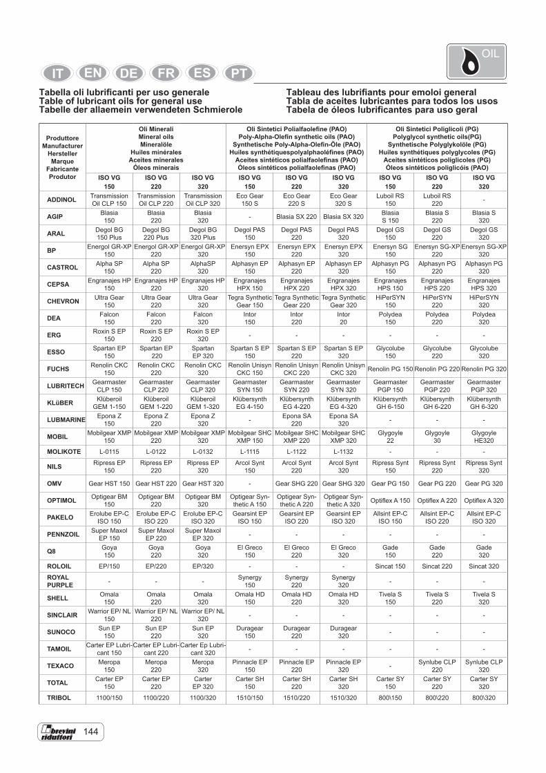
144
Tabella oli lubrificanti per uso generaleTable of lubricant oils for general useTabelle der allaemein verwendeten Schmierole
Tableau des lubrifiants pour emoloi generalTabla de aceites lubricantes para todos los usosTabela de óleos lubrìfìcantes para uso geral
ProduttoreManufacturer
HerstellerMarque
FabricanteProdutor
Oli MineraliMineral oilsMineralöle
Huiles minéralesAceites minerales
Óleos minerais
Oli Sintetici Polialfaolefine (PAO)Poly-Alpha-Olefin synthetic oils (PAO)
Synthetische Poly-Alpha-Olefin-Öle (PAO)Huiles synthétiquespolyalphaoléfìnes (PAO)
Aceites sintéticos polialfaolefinas (PAO)Óleos sintéticos polialfaolefinas (PAO)
Oli Sintetici Poliglicoli (PG)Polyglycol synthetic oils(PG)
Synthetische Polyglykolöle (PG)Huiles synthétiques polyglycoles (PG)
Aceites sintéticos poliglicoles (PG)Óleos sintéticos poliglicóis (PAO)
ISO VG ISO VG ISO VG ISO VG ISO VG ISO VG ISO VG ISO VG ISO VG 150 220 320 150 220 320 150 220 320
ADDINOL Transmission Oil CLP 150
Transmission Oil CLP 220
Transmission Oil CLP 320
Eco Gear 150 S
Eco Gear 220 S
Eco Gear 320 S
Luboil RS 150
Luboil RS 220 -
AGIP Blasia 150
Blasia 220
Blasia 320 - Blasia SX 220 Blasia SX 320 Blasia
S 150 Blasia S
220 Blasia S
320
ARAL Degol BG 150 Plus
Degol BG 220 Plus
Degol BG 320 Plus
Degol PAS 150
Degol PAS 220
Degol PAS 320
Degol GS 150
Degol GS 220
Degol GS 320
BP Energol GR-XP 150
Energol GR-XP 220
Energol GR-XP 320
Enersyn EPX 150
Enersyn EPX 220
Enersyn EPX 320
Enersyn SG 150
Enersyn SG-XP 220
Enersyn SG-XP 320
CASTROL Alpha SP 150
Alpha SP 220
AlphaSP 320
Alphasyn EP 150
Alphasyn EP 220
Alphasyn EP 320
Alphasyn PG 150
Alphasyn PG 220
Alphasyn PG 320
CEPSA Engranajes HP 150
Engranajes HP 220
Engranajes HP 320
Engranajes HPX 150
Engranajes HPX 220
Engranajes HPX 320
Engranajes HPS 150
Engranajes HPS 220
Engranajes HPS 320
CHEVRON Ultra Gear150
Ultra Gear 220
Ultra Gear 320
Tegra Synthetic Gear 150
Tegra Synthetic Gear 220
Tegra Synthetic Gear 320
HiPerSYN 150
HiPerSYN 220
HiPerSYN 320
DEA Falcon 150
Falcon 220
Falcon 320
Intor 150
Intor 220
Intor 20
Polydea 150
Polydea 220
Polydea 320
ERG Roxin S EP 150
Roxin S EP 220
Roxin S EP 320 - - - - - -
ESSO Spartan EP 150
Spartan EP 220
Spartan EP 320
Spartan S EP 150
Spartan S EP 220
Spartan S EP 320
Glycolube 150
Glycolube 220
Glycolube 320
FUCHS Renolin CKC 150
Renolin CKC 220
Renolin CKC 320
Renolin Unisyn CKC 150
Renolin Unisyn CKC 220
Renolin Unisyn CKC 320 Renolin PG 150 Renolin PG 220 Renolin PG 320
LUBRITECH Gearmaster CLP 150
Gearmaster CLP 220
Gearmaster CLP 320
Gearmaster SYN 150
Gearmaster SYN 220
Gearmaster SYN 320
Gearmaster PGP 150
Gearmaster PGP 220
Gearmaster PGP 320
KLüBER Klüberoil GEM 1-150
Klüberoil GEM 1-220
Klüberoil GEM 1-320
Klübersynth EG 4-150
Klübersynth EG 4-220
Klübersynth EG 4-320
Klübersynth GH 6-150
Klübersynth GH 6-220
Klübersynth GH 6-320
LUBMARINE Epona Z 150
Epona Z 220
Epona Z 320 - Epona SA
220 Epona SA
320 - - -
MOBIL Mobilgear XMP 150
Mobilgear XMP 220
Mobilgear XMP 320
Mobilgear SHC XMP 150
Mobilgear SHC XMP 220
Mobilgear SHC XMP 320
Glygoyle 22
Glygoyle 30
Glygoyle HE320
MOLIKOTE L-0115 L-0122 L-0132 L-1115 L-1122 L-1132 - - -
NILS Ripress EP 150
Ripress EP 220
Ripress EP 320
Arcol Synt 150
Arcol Synt 220
Arcol Synt 320
Ripress Synt 150
Ripress Synt 220
Ripress Synt 320
OMV Gear HST 150 Gear HST 220 Gear HST 320 - Gear SHG 220 Gear SHG 320 Gear PG 150 Gear PG 220 Gear PG 320
OPTIMOL Optigear BM 150
Optigear BM 220
Optigear BM 320
Optigear Syn-thetic A 150
Optigear Syn-thetic A 220
Optigear Syn-thetic A 320 Optiflex A 150 Optiflex A 220 Optiflex A 320
PAKELO Erolube EP-C ISO 150
Erolube EP-C ISO 220
Erolube EP-C ISO 320
Gearsint EP ISO 150
Gearsint EP ISO 220
Gearsint EP ISO 320
Allsint EP-C ISO 150
Allsint EP-C ISO 220
Allsint EP-C ISO 320
PENNZOIL Super Maxol EP 150
Super Maxol EP 220
Super Maxol EP 320 - - - - - -
Q8 Goya 150
Goya 220
Goya 320
El Greco 150
El Greco 220
El Greco 320
Gade 150
Gade 220
Gade 320
ROLOIL EP/150 EP/220 EP/320 - - - Sincat 150 Sincat 220 Sincat 320
ROYALPURPLE - - - Synergy
150 Synergy
220 Synergy
320 - - -
SHELL Omala 150
Omala 220
Omala 320
Omala HD 150
Omala HD 220
Omala HD 320
Tivela S 150
Tivela S 220
Tivela S 320
SINCLAIR Warrior EP/ NL 150
Warrior EP/ NL 220
Warrior EP/ NL 320 - - - - - -
SUNOCO Sun EP 150
Sun EP 220
Sun EP 320
Duragear 150
Duragear 220
Duragear 320 - - -
TAMOIL Carter EP Lubri-cant 150
Carter EP Lubri-cant 220
Carter Ep Lubri-cant 320 - - - - - -
TEXACO Meropa 150
Meropa 220
Meropa 320
Pinnacle EP 150
Pinnacle EP 220
Pinnacle EP 320 - Synlube CLP
220 Synlube CLP
320
TOTAL Carter EP 150
Carter EP 220
Carter EP 320
Carter SH 150
Carter SH 220
Carter SH 320
Carter SY 150
Carter SY 220
Carter SY 320
TRIBOL 1100/150 1100/220 1100/320 1510/150 1510/220 1510/320 800\150 800\220 800\320
OIL
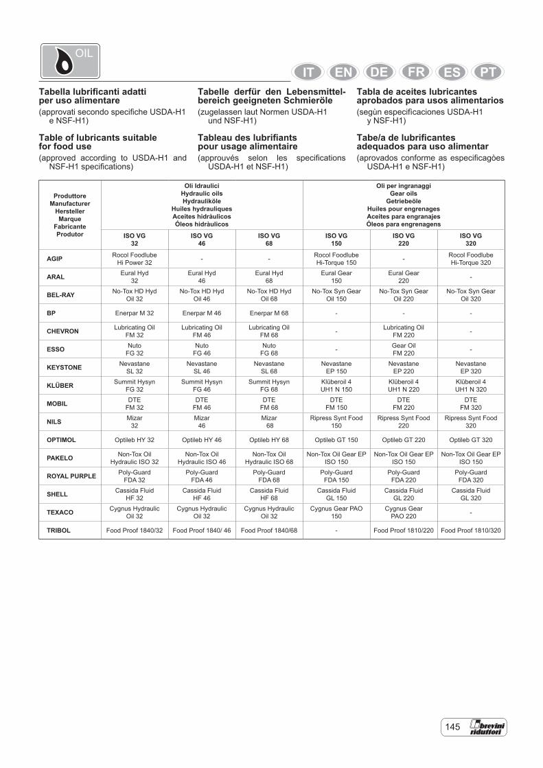
145
Tabella lubrificanti adattiper uso alimentare(approvati secondo specifiche USDA-H1
e NSF-H1)
Table of lubricants suitablefor food use(approved according to USDA-H1 and
NSF-H1 specifications)
Tabelle derfür den Lebensmittel-bereich geeigneten Schmieröle(zugelassen laut Normen USDA-H1
und NSF-H1)
Tableau des lubrifiantspour usage alimentaire(approuvés selon les specifications
USDA-H1 et NSF-H1)
Tabla de aceites lubricantesaprobados para usos alimentarios(segùn especifìcaciones USDA-H1
y NSF-H1)
Tabe/a de lubrificantesadequados para uso alimentar(aprovados conforme as especificagòes
USDA-H1 e NSF-H1)
ProduttoreManufacturer
HerstellerMarque
FabricanteProdutor
Oli IdrauliciHydraulic oilsHydrauliköle
Huiles hydrauliquesAceites hidràulicosÓleos hidràulicos
Oli per ingranaggiGear oils
GetriebeöleHuiles pour engrenagesAceites para engranajesÓleos para engrenagens
ISO VG32
ISO VG 46
ISO VG 68
ISO VG 150
ISO VG 220
ISO VG 320
AGIP Rocol FoodlubeHi Power 32 - - Rocol Foodlube
Hi-Torque 150 - Rocol FoodlubeHi-Torque 320
ARAL Eural Hyd 32
Eural Hyd 46
Eural Hyd 68
Eural Gear 150
Eural Gear 220 -
BEL-RAY No-Tox HD HydOil 32
No-Tox HD HydOil 46
No-Tox HD HydOil 68
No-Tox Syn GearOil 150
No-Tox Syn GearOil 220
No-Tox Syn GearOil 320
BP Enerpar M 32 Enerpar M 46 Enerpar M 68 - - -
CHEVRON Lubricating Oil FM 32
Lubricating Oil FM 46
Lubricating Oil FM 68 - Lubricating Oil
FM 220 -
ESSO Nuto FG 32
Nuto FG 46
Nuto FG 68 - Gear Oil
FM 220 -
KEYSTONE Nevastane SL 32
Nevastane SL 46
Nevastane SL 68
Nevastane EP 150
Nevastane EP 220
Nevastane EP 320
KLÜBER Summit Hysyn FG 32
Summit Hysyn FG 46
Summit Hysyn FG 68
Klüberoil 4 UH1 N 150
Klüberoil 4 UH1 N 220
Klüberoil 4 UH1 N 320
MOBIL DTE FM 32
DTE FM 46
DTE FM 68
DTE FM 150
DTE FM 220
DTE FM 320
NILS Mizar 32
Mizar 46
Mizar 68
Ripress Synt Food 150
Ripress Synt Food 220
Ripress Synt Food 320
OPTIMOL Optileb HY 32 Optileb HY 46 Optileb HY 68 Optileb GT 150 Optileb GT 220 Optileb GT 320
PAKELO Non-Tox Oil Hydraulic ISO 32
Non-Tox Oil Hydraulic ISO 46
Non-Tox Oil Hydraulic ISO 68
Non-Tox Oil Gear EP ISO 150
Non-Tox Oil Gear EP ISO 150
Non-Tox Oil Gear EP ISO 150
ROYAL PURPLE Poly-Guard FDA 32
Poly-Guard FDA 46
Poly-Guard FDA 68
Poly-Guard FDA 150
Poly-Guard FDA 220
Poly-Guard FDA 320
SHELL Cassida Fluid HF 32
Cassida Fluid HF 46
Cassida Fluid HF 68
Cassida FluidGL 150
Cassida Fluid GL 220
Cassida FluidGL 320
TEXACO Cygnus Hydraulic Oil 32
Cygnus Hydraulic Oil 32
Cygnus Hydraulic Oil 32
Cygnus Gear PAO 150
Cygnus Gear PAO 220 -
TRIBOL Food Proof 1840/32 Food Proof 1840/ 46 Food Proof 1840/68 - Food Proof 1810/220 Food Proof 1810/320
OIL
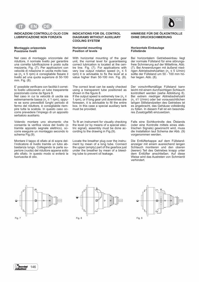
146
INDICAZIONI CONTROLLO OLIO CON LUBRIFICAZIONE NON FORZATA
Montaggio orizzontalePosizione livelli
Nel caso di montaggio orizzontale del riduttore, il normale livello per garantire una corretta lubrificazione è posto sulla mezzeria, Fig. (7). Per applicazioni con velocità di rotazione in uscita molto bas-sa (n2 ≤ 5 rpm) è consigliabile fissare il livello ad una quota superiore di 50-100 mm. Fig. (8).
E’ possibile verificare con facilità il corret-to livello utilizzando un tubo trasparente posizionato come da figura 8.Nel caso in cui la velocità di uscita sia estremamente bassa (n2 ≤ 1 rpm), oppu-re se sono prevedibili lunghi periodo di fermo del riduttore, è consigliabile riem-pire tutta la scatola. In questo caso oc-corre prevedere l’impiego di un apposito serbatoio ausiliario.
Volendo montare uno strumento che consenta la verifica visiva del livello (o tramite apposito segnale elettrico), oc-corre eseguire un montaggio secondo lo schema Fig.(9).
Montare il tappo di sfiato al di sopra del-l’indicatore di livello tramite un tubo ab-bastanza lungo. Collegando la parte su-periore (vuota) del riduttore appena sotto allo sfiato. In questo modo si eviterà la fuoriuscita di olio.
INDICATIONS FOR OIL CONTROL DIAGRAMS WITHOUT AUXILIARY COOLING SYSTEM
HINWEISE FÜR DIE ÖLKONTROLLE OHNE DRUCKSCHMIERUNG
With horizontal mounting of the gear unit, the normal level for guaranteeing correct lubrication is located at the cen-tre line. Fig. (7). For applications with very low output rotation speed (n2 ≤ 5 rpm) it is advisable to fix the level at a value higher than 50-100 mm. Fig. (8).
The correct level can be easily checked using a transparent tube positioned as shown in the figure 8.If the output speed is extremely low (n2 ≤ 1 rpm), or if long gear unit downtimes are foreseen, it is advisable to fill the entire box. In this case a special auxiliary tank must be provided.
To fit an instrument for visually checking the level (or by means of a special elec-tric signal), assembly must be done ac-cording to the drawing in Fig.(9).
Locate the breather plug over the instru-ment by mean of a long tube. Connect the upper (empty) part of the gearbox just under the breather by mean of a bleed-ing tube to prevent oil leakage.
Bei horizontalem Getriebeeinbau liegt der normale Füllstand für eine störungs-freie Schmierung auf der Mittellinie, Abb. (7). Bei Anwendungen mit äußerst nied-rigen Abtriebsdrehzahlen (n2 ≤ 5 U/min) sollte der Füllstand um 50 - 100 mm hö-her liegen. Abb. (8).
Der vorschriftsmäßige Füllstand kann leicht mit einem durchsichtigen Schlauch kontrolliert werden (siehe Abbildung 8). Bei extrem niedriger Abtriebsdrehzahl (n2 ≤1 U/min) oder bei voraussichtlichen langen Stillstandzeiten des Getriebes ist es angebracht, das Gehäuse vollständig zu füllen. In diesem Fall ist ein besonde-res Zusatzgefäß einzusetzen.
Falls eine Sichtkontrolle des Ölstands (oder eine Kontrolle mittels eines elek-trischen Signals) gewünscht wird, muss die Installation laut Schema der Abb. (9) vorgenommen werden.
Die Entlüfterkappe auf dem Füllstand-anzeiger mit einem ausreichend langen Schlauch montieren und den oberen (leeren) Teil des Getriebes knapp unter dem Entlüfter anschließen. Auf diese Weise wird das Austreten von Schmieröl verhindert.
Horizontal mountingPosition of levels
Horizontale EinbaulageFüllstände
Fig. 7 Fig. 8 Fig. 9
OIL
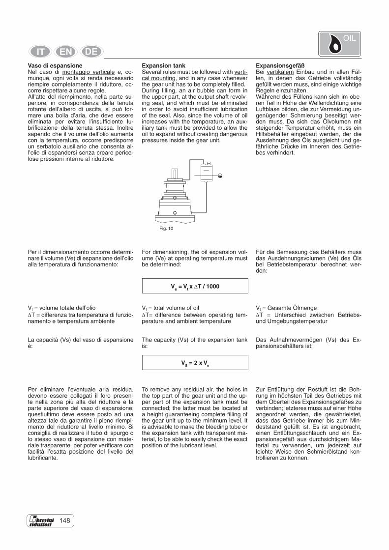
148
Vaso di espansioneNel caso di montaggio verticale e, co-munque, ogni volta si renda necessario riempire completamente il riduttore, oc-corre rispettare alcune regole.All’atto del riempimento, nella parte su-periore, in corrispondenza della tenuta rotante dell’albero di uscita, si può for-mare una bolla d’aria, che deve essere eliminata per evitare l’insufficiente lu-brificazione della tenuta stessa. Inoltre sapendo che il volume dell’olio aumenta con la temperatura, occorre predisporre un serbatoio ausiliario che consenta al-l’olio di espandersi senza creare perico-lose pressioni interne al riduttore.
Per il dimensionamento occorre determi-nare il volume (Ve) di espansione dell’olio alla temperatura di funzionamento:
Vt = volume totale dell’olio∆T = differenza tra temperatura di funzio-namento e temperatura ambiente
La capacità (Vs) del vaso di espansione è:
Per eliminare l’eventuale aria residua, devono essere collegati il foro presen-te nella zona più alta del riduttore e la parte superiore del vaso di espansione; questiultimo deve essere posto ad una altezza tale da garantire il pieno riempi-mento del riduttore al livello minimo. Si consiglia di realizzare il tubo di spurgo o lo stesso vaso di espansione con mate-riale trasparente, per poter verificare con facilità l’esatta posizione del livello del lubrificante.
Expansion tankSeveral rules must be followed with verti-cal mounting, and in any case whenever the gear unit has to be completely filled.During filling, an air bubble can form in the upper part, at the output shaft revolv-ing seal, and which must be eliminated in order to avoid insufficient lubrication of the seal. Also, since the volume of oil increases with the temperature, an aux-iliary tank must be provided to allow the oil to expand without creating dangerous pressures inside the gear unit.
For dimensioning, the oil expansion vol-ume (Ve) at operating temperature must be determined:
Vt = total volume of oil∆T= difference between operating tem-perature and ambient temperature
The capacity (Vs) of the expansion tank is:
To remove any residual air, the holes in the top part of the gear unit and the up-per part of the expansion tank must be connected; the latter must be located at a height guaranteeing complete filling of the gear unit up to the minimum level. It is advisable to make the bleeding tube or the expansion tank with transparent ma-terial, to be able to easily check the exact position of the lubricant level.
ExpansionsgefäßBei vertikalem Einbau und in allen Fäl-len, in denen das Getriebe vollständig gefüllt werden muss, sind einige wichtige Regeln einzuhalten.Während des Füllens kann sich im obe-ren Teil in Höhe der Wellendichtung eine Luftblase bilden, die zur Vermeidung un-genügender Schmierung beseitigt wer-den muss. Da sich das Ölvolumen mit steigender Temperatur erhöht, muss ein Hilfsbehälter eingebaut werden, der die Ausdehnung des Öls ausgleicht und ge-fährliche Drücke im Inneren des Getrie-bes verhindert.
Für die Bemessung des Behälters muss das Ausdehnungsvolumen (Ve) des Öls bei Betriebstemperatur berechnet wer-den:
Vt = Gesamte Ölmenge∆T = Unterschied zwischen Betriebs- und Umgebungstemperatur
Das Aufnahmevermögen (Vs) des Ex-pansionsbehälters ist:
Zur Entlüftung der Restluft ist die Boh-rung im höchsten Teil des Getriebes mit dem Oberteil des Expansionsgefäßes zu verbinden; letzteres muss auf einer Höhe angeordnet werden, die gewährleistet, dass das Getriebe immer bis zum Min-deststand gefüllt ist. Es ist angebracht, einen Entlüftungsschlauch und ein Ex-pansionsgefäß aus durchsichtigem Ma-terial zu verwenden, um jederzeit auf leichte Weise den Schmierölstand kon-trollieren zu können.
Fig. 10
Ve = Vt x ∆T / 1000
VS = 2 x Ve
OIL
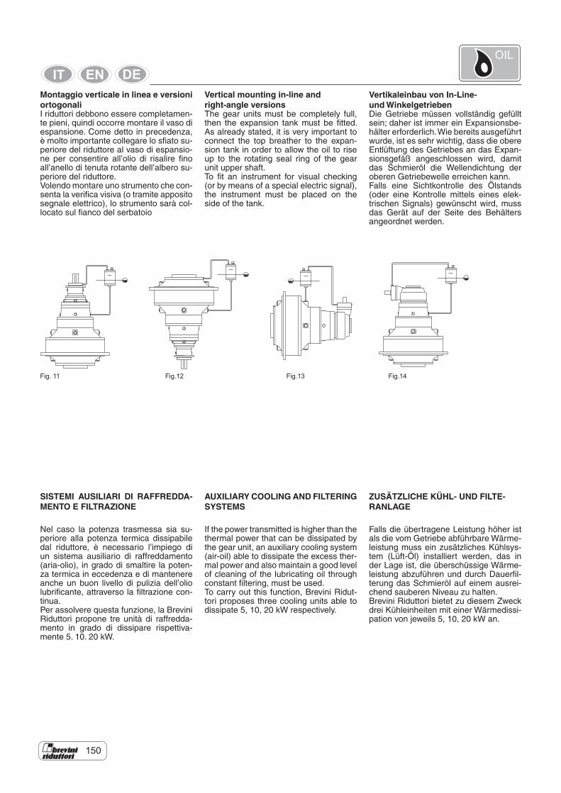
150
Montaggio verticale in linea e versioni ortogonaliI riduttori debbono essere completamen-te pieni, quindi occorre montare il vaso di espansione. Come detto in precedenza, è molto importante collegare lo sfiato su-periore del riduttore al vaso di espansio-ne per consentire all’olio di risalire fino all’anello di tenuta rotante dell’albero su-periore del riduttore.Volendo montare uno strumento che con-senta la verifica visiva (o tramite apposito segnale elettrico), lo strumento sarà col-locato sul fianco del serbatoio
Vertical mounting in-line andright-angle versionsThe gear units must be completely full, then the expansion tank must be fitted. As already stated, it is very important to connect the top breather to the expan-sion tank in order to allow the oil to rise up to the rotating seal ring of the gear unit upper shaft.To fit an instrument for visual checking (or by means of a special electric signal), the instrument must be placed on the side of the tank.
Vertikaleinbau von In-Line-und WinkelgetriebenDie Getriebe müssen vollständig gefüllt sein; daher ist immer ein Expansionsbe-hälter erforderlich. Wie bereits ausgeführt wurde, ist es sehr wichtig, dass die obere Entlüftung des Getriebes an das Expan-sionsgefäß angeschlossen wird, damit das Schmieröl die Wellendichtung der oberen Getriebewelle erreichen kann.Falls eine Sichtkontrolle des Ölstands (oder eine Kontrolle mittels eines elek-trischen Signals) gewünscht wird, muss das Gerät auf der Seite des Behälters angeordnet werden.
Fig. 11
SISTEMI AUSILIARI DI RAFFREDDA-MENTO E FILTRAZIONE
Nel caso la potenza trasmessa sia su-periore alla potenza termica dissipabile dal riduttore, è necessario l’impiego di un sistema ausiliario di raffreddamento (aria-olio), in grado di smaltire la poten-za termica in eccedenza e di mantenere anche un buon livello di pulizia dell’olio lubrificante, attraverso la filtrazione con-tinua.Per assolvere questa funzione, la Brevini Riduttori propone tre unità di raffredda-mento in grado di dissipare rispettiva-mente 5. 10. 20 kW.
AUXILIARY COOLING AND FILTERING SYSTEMS
If the power transmitted is higher than the thermal power that can be dissipated by the gear unit, an auxiliary cooling system (air-oil) able to dissipate the excess ther-mal power and also maintain a good level of cleaning of the lubricating oil through constant filtering, must be used.To carry out this function, Brevini Ridut-tori proposes three cooling units able to dissipate 5, 10, 20 kW respectively.
ZUSÄTZLICHE KÜHL- UND FILTE-RANLAGE
Falls die übertragene Leistung höher ist als die vom Getriebe abführbare Wärme-leistung muss ein zusätzliches Kühlsys-tem (Lüft-Öl) installiert werden, das in der Lage ist, die überschüssige Wärme-leistung abzuführen und durch Dauerfil-terung das Schmieröl auf einem ausrei-chend sauberen Niveau zu halten. Brevini Riduttori bietet zu diesem Zweck drei Kühleinheiten mit einer Wärmedissi-pation von jeweils 5, 10, 20 kW an.
Fig.12 Fig.13 Fig.14
OIL
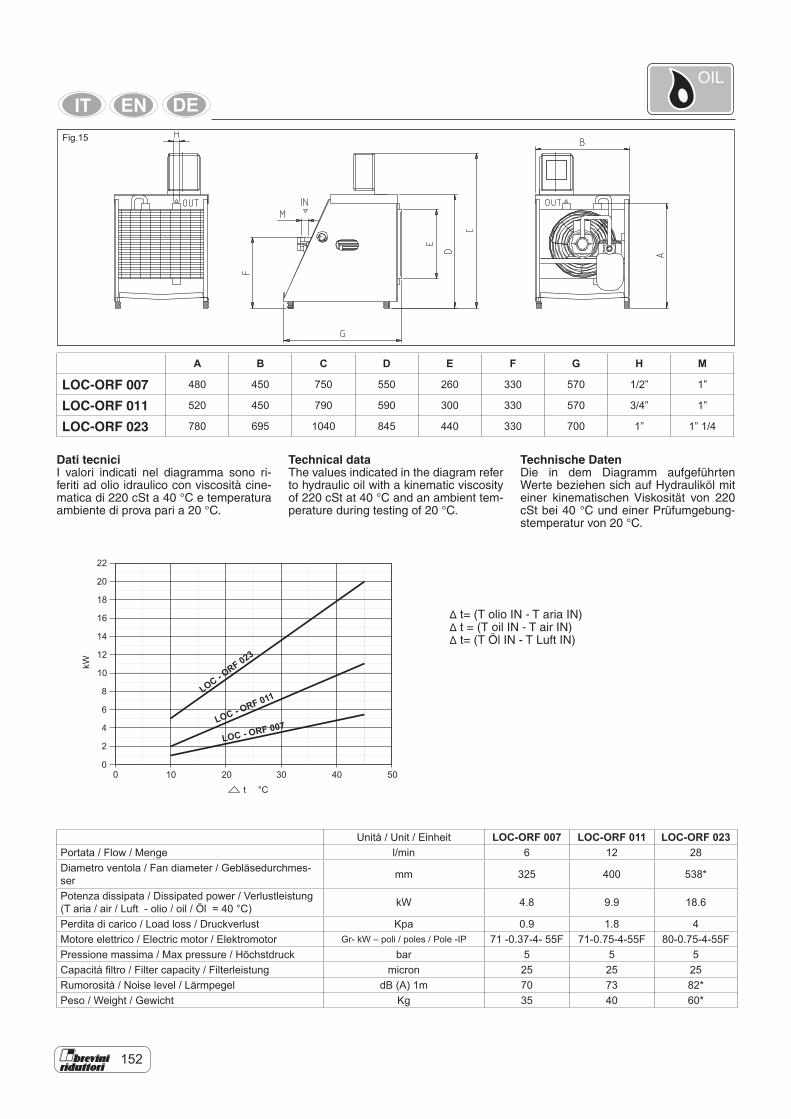
152
Dati tecniciI valori indicati nel diagramma sono ri-feriti ad olio idraulico con viscosità cine-matica di 220 cSt a 40 °C e temperatura ambiente di prova pari a 20 °C.
A B C D E F G H M
LOC-ORF 007 480 450 750 550 260 330 570 1/2” 1”
LOC-ORF 011 520 450 790 590 300 330 570 3/4” 1”
LOC-ORF 023 780 695 1040 845 440 330 700 1” 1” 1/4
0
2
4
6
8
10
12
14
16
18
20
0 10 20 30 40 50
kW
22
t °C
LOC - ORF 023
LOC - ORF 011
LOC - ORF 007
Δ t= (T olio IN - T aria IN)Δ t = (T oil IN - T air IN)Δ t= (T Öl IN - T Luft IN)
Technical dataThe values indicated in the diagram refer to hydraulic oil with a kinematic viscosity of 220 cSt at 40 °C and an ambient tem-perature during testing of 20 °C.
Unità / Unit / Einheit LOC-ORF 007 LOC-ORF 011 LOC-ORF 023Portata / Flow / Menge l/min 6 12 28Diametro ventola / Fan diameter / Gebläsedurchmes-ser mm 325 400 538*
Potenza dissipata / Dissipated power / Verlustleistung (T aria / air / Luft - olio / oil / Öl = 40 °C) kW 4.8 9.9 18.6
Perdita di carico / Load loss / Druckverlust Kpa 0.9 1.8 4Motore elettrico / Electric motor / Elektromotor Gr- kW – poli / poles / Pole -IP 71 -0.37-4- 55F 71-0.75-4-55F 80-0.75-4-55FPressione massima / Max pressure / Höchstdruck bar 5 5 5Capacità filtro / Filter capacity / Filterleistung micron 25 25 25Rumorosità / Noise level / Lärmpegel dB (A) 1m 70 73 82* Peso / Weight / Gewicht Kg 35 40 60*
Technische DatenDie in dem Diagramm aufgeführten Werte beziehen sich auf Hydrauliköl mit einer kinematischen Viskosität von 220 cSt bei 40 °C und einer Prüfumgebung-stemperatur von 20 °C.
Fig.15
OIL
154
Le centraline sono composte da uno scambiatore di calore aria-olio, un filtro, un motore elettrico, una pompa a tre viti con valvola di sicurezza e un ventilatore coassiale e solidale alla pompa, con pa-lette inclinate in funzione della frequenza di azionamento del motore per contene-re la rumorosità.Il sistema è dotato di un termostato che consente l’avviamento della pompa solo quando la temperatura dell’olio è com-presa tra 20 °C e 30 °C per evitare di pompare olio freddo, eccessivamente viscoso, con conseguente innalzamento della pressione nel circuito.E’ dotato inoltre del necessario quadro elettrico; per ulteriori informazioni con-tattare il Servizio Tecnico Commerciale della Brevini Riduttori.Volendo montare un sistema ausiliario diverso, ricordiamo che è assolutamente sconsigliato l’impiego di impianti con ser-batoio esterno.Nel caso in cui si renda necessario un serbatoio ausiliario (per es. per raffred-dare più riduttori con un unico impianto) consigliamo di contattare il Servizio Tec-nico Commerciale della Brevini Riduttori.Progettando un circuito di circolazione dell’olio è consigliabile aspirare nel punto più basso, così questo ramo del circuito può servire anche a vuotare il ridutto-re. In ogni caso i punti di aspirazione e mandata dell’olio debbono essere suffi-cientemente lontani tra loro per garantire l’attraversamento del riduttore dell’olio fresco.Il diametro dei fori di passaggio dell’olio, soprattutto in aspirazione, è molto im-portante. Infatti, in presenza di fori trop-po stretti, la pompa tende a cavitare. Non potendo modificare la portata della pompa, che è funzione della potenza da smaltire, occorre verificare la capa-cità dei fori. Quando si aspira l’olio dai supporti in entrata o dalle flange delle riduzioni veloci. l’impiego di un solo foro, può essere insufficiente a smaltire tutta la portata pertanto occorre collegare 2 o 3 fori mediante un collettore collegato al tubo di aspirazione.La mandata è solitamente meno proble-matica poiché, nel caso di portata natu-rale insufficiente, si genera una piccola pressione che garantisce il flusso.Per un corretto dimensionamento del cir-cuito, si consiglia di seguire le seguenti regole.Aspirazione:aspirare da più fori quando, usando un solo foro, la velocità dell’olio V è superio-re a 1.30 m/s;Mandata:mandare in più fori quando, usando un solo foro, la velocità dell’olio V è superio-re a 2.10 m/s.
The units are formed of an air-oil cooler, a filter, an electric motor, a pump with three screws with safety valve and a coaxial fan integral with the pump, with impellers inclined according to the frequency of motor operation to limit noise. The system is equipped with a thermo-stat that allows pump start only when the oil temperature is between 20 °C and 30 °C to avoid pumping cold, and excessive-ly viscous oil, with subsequent pressure rise in the circuit.It is also equipped with the necessary electrical panel; for further information contact the Brevini Riduttori Technical Commercial Service.If a different auxiliary system is to be fit-ted, do not use systems with an external tank. If an auxiliary tank is required (e.g. for cooling several gear units with a single system) it is advisable to contact the Brevini Riduttori Technical Commercial Service.In designing an oil circulating circuit it is advisable for suction to be in the lowest point, so that this branch of the circuit can also be used to drain the gear unit. In any case, the oil suction and delivery points must be far enough apart to ensure fresh oil crossing the gear unit. The diameter of the oil passage is very important, above all in suction. In fact, with too narrow holes, the pump tends to cavitate. Not being able to change the pump delivery, which is a function of the power to be dissipated, the capacity of the holes must be verified. When sucking from input shafts or the flanges of the fast reducers, the use of one hole may be insufficient to dissipate all the flow therefore 2 or 3 holes must be connected by means of a manifold con-nected to the suction pipe.Delivery is usually less problematic since, in the event of insufficient natural capac-ity, a small pressure is generated which guarantees the flow. For correct dimensioning of the circuit, it is advisable to follow these rules.Suction:provide for suction from several holes when, using just one hole, the oil velocity V is higher than 1.30 m/s;Delivery:deliver in several holes when, using just one hole, the oil velocity V is higher than 2.10 m/s.
Die Einheiten bestehen aus einem Luft-Öl-Wärmetauscher, einem Filter, einem Elektromotor, einer Dreischraubenpum-pe mit Sicherheitsventil und einem Ge-bläse, das koaxial fest mit der Pumpe verbunden ist; die Ventilatorflügel sind für bessere Laufruhe in Abhängigkeit von der Einschalthäufigkeit des Motors geneigt.Die Anlage ist mit einem Thermostaten ausgestattet, der die Pumpe nur bei einer Öltemperatur zwischen 20 °C und 30 °C einschaltet, um zu vermeiden, dass kaltes, sehr zähflüssiges Schmieröl ge-pumpt wird, was wiederum zu einer Dru-ckerhöhung im Kreislauf führen würde. Zur Ausstattung gehört ebenfalls eine lektrische Schalttafel; wenden Sie sich für weitere Informationen an die techni-sche Verkaufsberatung Brevini Riduttori.Falls der Einbau eines anderen Hilfssys-tems gewünscht wird, weisen wir darauf hin, dass auf keinen Fall Anlagen mit externem Behälter eingesetzt werden dürfen.Falls ein Zusatztank erforderlich sein sollte (um z. B. mehrere Getriebe mit einer ein-zigen Anlage zu kühlen), wenden Sie sich bitte zuvor an die technische Verkaufsbe-ratung Brevini Riduttori.Bei der Planung einer Ölumlaufschmie-rung sollte die Ansaugung am niedrigsten Punkt des Kreislaufs angeordnet wer-den, so dass derselbe auch zum Entlee-ren des Getriebes dient. Die Rück- und Vorlaufpunkte des Schmieröls müssen in jedem Fall in einem ausreichenden Abstand von einander angeordnet sein, damit das Frischöl das gesamte Getriebe durchströmen kann.Der Durchmesser der Bohrungen des Öldurchflusses, besonders der saugsei-tigen, ist extrem wichtig. Bei zu engen Bohrungen tendiert die Pumpe zum Kavitieren. Da die Pumpenfördermen-ge, die eine Funktion der abzuführen-den Leistung ist, nicht geändert werden kann, ist die Kapazität der Durchlässe zu kontrollieren. Wenn Öl von den An-triebswellen oder den Flanschverbindun-gen der Schnellgetriebe angesaugt wird, kann die Verwendung einer einzigen Bohrung unzureichend sein, um die ge-samte Leistung abzuführen; es ist daher erforderlich, 2 oder 3 Bohrungen mit ei-ner Sammelleitung an das Saugrohr an-zuschließen.Die Druckseite weist weniger Schwierig-keiten auf, da bei unzureichender För-dermenge ein kleiner Druck entsteht, der für den notwendigen Durchfluss sorgt.Befolgen Sie für eine korrekte Bemessung des Kreislaufs die folgenden Hinweise. Ansaugung:Für die Ansaugung mehrere Bohrungen benutzen, wenn bei nur einer Bohrung die Ölgeschwindigkeit V höher als 1.30 m/s ist; Druckseite:Für die Förderung mehrere Bohrungen benutzen, wenn bei nur einer Bohrung die Ölgeschwindigkeit V höher als 2.10 m/s ist.
OIL
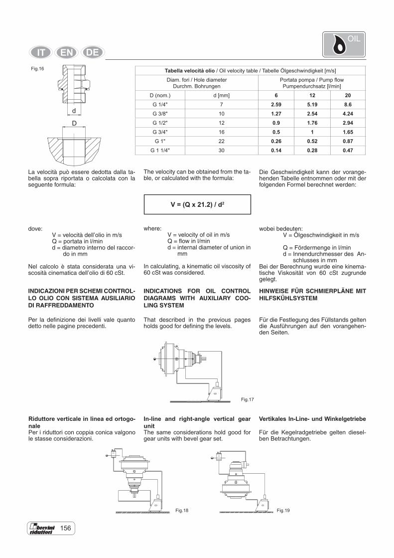
156
Tabella velocità olio / Oil velocity table / Tabelle Ölgeschwindigkeit [m/s]
Diam. fori / Hole diameter Durchm. Bohrungen
Portata pompa / Pump flow Pumpendurchsatz [l/min]
D (nom.) d [mm] 6 12 20G 1/4" 7 2.59 5.19 8.6G 3/8" 10 1.27 2.54 4.24G 1/2" 12 0.9 1.76 2.94G 3/4" 16 0.5 1 1.65G 1" 22 0.26 0.52 0.87
G 1 1/4" 30 0.14 0.28 0.47
La velocità può essere dedotta dalla ta-bella sopra riportata o calcolata con la seguente formula:
dove: V = velocità dell’olio in m/s Q = portata in l/min d = diametro interno del raccor- do in mm
Nel calcolo è stata considerata una vi-scosità cinematica dell’olio di 60 cSt.
V = (Q x 21.2) / d2
INDICAZIONI PER SCHEMI CONTROL-LO OLIO CON SISTEMA AUSILIARIO DI RAFFREDDAMENTO
Per la definizione dei livelli vale quanto detto nelle pagine precedenti.
The velocity can be obtained from the ta-ble, or calculated with the formula:
where: V = velocity of oil in m/s Q = flow in l/min d = internal diameter of union in mm
In calculating, a kinematic oil viscosity of 60 cSt was considered.
INDICATIONS FOR OIL CONTROL DIAGRAMS WITH AUXILIARY COO-LING SYSTEM
That described in the previous pages holds good for defining the levels.
Die Geschwindigkeit kann der vorange-henden Tabelle entnommen oder mit der folgenden Formel berechnet werden:
wobei bedeuten: V = Ölgeschwindigkeit in m/s
Q = Fördermenge in l/min d = Innendurchmesser des An- schlusses in mm Bei der Berechnung wurde eine kinema-tische Viskosität von 60 cSt zugrunde gelegt.
HINWEISE FÜR SCHMIERPLÄNE MIT HILFSKÜHLSYSTEM
Für die Festlegung des Füllstands gelten die Ausführungen auf den vorangehen-den Seiten.
d
D
In-line and right-angle vertical gear unitThe same considerations hold good for gear units with bevel gear set.
Fig.16
Fig.17
Fig.18 Fig.19
Riduttore verticale in linea ed ortogo-nalePer i riduttori con coppia conica valgono le stasse considerazioni.
Vertikales In-Line- und Winkelgetriebe
Für die Kegelradgetriebe gelten diesel-ben Betrachtungen.
OIL
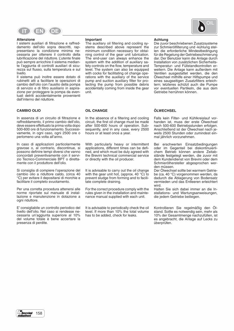
158
AttenzioneI sistemi ausiliari di filtrazione e raffred-damento dell’olio sopra descritti, rap-presentano la condizione minima ne-cessaria per ottenere il controllo della lubrificazione del riduttore. L’utente finale può sempre arricchire il sistema median-te l’aggiunta di controlli ausiliari di sicu-rezza sul flusso, sulla temperatura e sul livello.Il sistema può inoltre essere dotato di rubinetti atti a facilitare le operazioni di cambio dell’olio con l’ausilio della pompa di servizio e di filtro ausiliario in aspira-zione per proteggere la pompa da even-tuali detriti accidentalmente provenienti dall’interno del riduttore.
CAMBIO OLIO
In assenza di un circuito di filtrazione e raffreddamento, il primo cambio dell’olio, deve essere effettuato la prima volta dopo 500-600 ore di funzionamento. Successi-vamente, in ogni caso, ogni 2500 ore o perlomeno una volta all’anno.
In caso di applicazioni particolarmente gravose o, al contrario, discontinue, si possono definire tempi diversi che vanno concordati preventivamente con il servi-zio Tecnico-Commerciale BPT o diretta-mente con il produttore dell’olio.
Si consiglia di compiere l’operazione del cambio olio a riduttore caldo, (circa 40 °C) per evitare il depositarsi di morchie e facilitare il completo svuotamento.
Per una corretta procedura attenersi alle norme riportate sul manuale di instal-lazione e manutenzione in dotazione a ogni riduttore.
E’ consigliabile un controllo periodico del livello dell’olio. Nel caso si rendesse ne-cessaria un’aggiunta superiore al 10% del volume totale è bene accertare la presenza di perdite.
ImportantThe auxiliary oil filtering and cooling sy-stems described above represent the minimum condition necessary for obtai-ning control of the gear unit lubrication. The end-user can always enhance the system with the addition of auxiliary sa-fety controls on the flow, temperature and level. The system can also be equipped with cocks for facilitating oil change ope-rations with the auxiliary of the service pump and suction auxiliary filter for pro-tecting the pump from possible debris accidentally coming from inside the gear unit.
OIL CHANGE
In the absence of a filtering and cooling circuit, the first oil change must be made after 500-600 hours of operation. Sub-sequently, and in any case, every 2500 hours or at least once a year.
With particularly heavy or intermittent applications, different times can be defi-ned, and which must be duly agreed with the Brevini technical commercial service or directly with the oil producer.
It is advisable to carry out the oil change with the gear unit hot, (approx. 40 °C) to prevent sludge from forming and to facili-tate complete draining.
For the correct procedure comply with the rules given in the installation and mainte-nance manual supplied with each unit.
It is advisable to periodically check the oil level. If more than 10% the total volume has to be added, check for leaks.
AchtungDie zuvor beschriebenen Zusatzsysteme zur Schmierölfilterung und -kühlung stel-len die erforderliche Mindestbedingung für die Regelung der Getriebeschmierung dar. Der Benutzer kann die Anlage durch Installation von zusätzlichen Sicherheits-Temperatur- und Füllstandkontrollen er-weitern. Die Anlage kann außerdem mit Ventilen ausgestattet werden, die den Ölwechsel mithilfe einer Hilfspumpe und eines saugseitigen Zusatzfilters erleich-tern; letzteres schützt auch die Pumpe vor eventuellen Partikeln, die aus dem Getriebe herrühren können.
ÖLWECHSEL
Falls kein Filter- und Kühlkreislauf vor-handen ist, muss der erste Ölwechsel nach 500-600 Betriebsstunden erfolgen. Anschließend ist der Ölwechsel nach je-weils 2500 Stunden oder zumindest ein-mal jährlich vorzunehmen.
Bei erschwerten Einsatzbedingungen oder im Gegenteil bei diskontinuierli-chem Betrieb können andere Zeitab-stände festgelegt werden, die zuvor mit dem Kundendienst von Brevini oder dem Schmierölhersteller abgesprochen wer-den müssen. Der Ölwechsel sollte bei warmem Getrie-be (ca. 40 °C) vorgenommen werden, da dadurch die Ablagerung von Bodensatz vermieden und das Entleeren erleichtert wird. Halten Sie sich dabei immer an die In-stallations- und Wartungsanweisungen, die jedem Getriebe beiliegen.
Kontrollieren Sie regelmäßig den Öl-stand. Sollte es notwendig sein, mehr als 10% der Gesamtmenge nachzufüllen, ist es angebracht, die Anlage auf Lecks zu überprüfen.
OIL
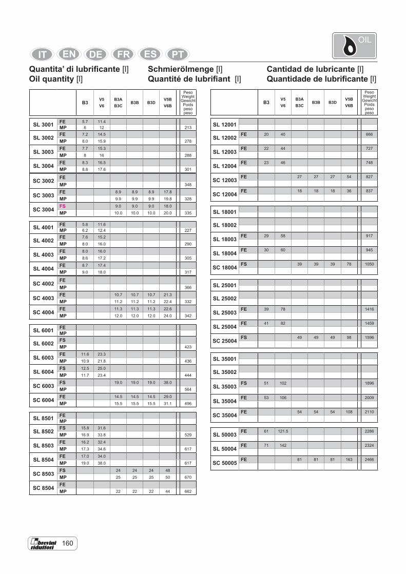
160
Quantita’ di lubrificante [l]Oil quantity [l]
Cantidad de lubricante [l]Quantidade de lubrificante [l]
B3V5 V6
B3A B3C
B3B B3DV5B V6B
Peso Weight Gewicht Poids peso peso
B3V5 V6
B3A B3C
B3B B3DV5B V6B
Peso Weight Gewicht Poids peso peso
Schmierölmenge [l]Quantité de lubrifiant [l]
OIL
SL 3001 FE 5.7 11.4MP 6 12 213
SL 3002 FE 7.2 14.5
MP 8.0 15.9 278
SL 3003 FE 7.7 15.3
MP 8 16 288
SL 3004 FE 8.3 16.5
MP 8.8 17.6 301
SC 3002 FEMP 348
SC 3003 FE 8.9 8.9 8.9 17.8
MP 9.9 9.9 9.9 19.8 328
SC 3004 FS 9.0 9.0 9.0 18.0
MP 10.0 10.0 10.0 20.0 335
SL 4001 FE 5.8 11.6MP 6.2 12.4 227
SL 4002 FE 7.6 15.2
MP 8.0 16.0 290
SL 4003 FE 8.0 16.0
MP 8.6 17.2 305
SL 4004 FE 8.7 17.4
MP 9.0 18.0 317
SC 4002 FEMP 366
SC 4003 FE 10.7 10.7 10.7 21.3
MP 11.2 11.2 11.2 22.4 332
SC 4004 FE 11.3 11.3 11.3 22.6
MP 12.0 12.0 12.0 24.0 342
SL 6001 FEMP
SL 6002 FSMP 423
SL 6003 FE 11.6 23.3
MP 10.9 21.8 436
SL 6004 FS 12.5 25.0
MP 11.7 23.4 444
SC 6003 FS 19.0 19.0 19.0 38.0
MP 564
SC 6004 FE 14.5 14.5 14.5 29.0
MP 15.5 15.5 15.5 31.1 496
SL 8501 FEMP
SL 8502 FS 15.8 31.6
MP 16.9 33.8 529
SL 8503 FE 16.2 32.4
MP 17.3 34.6 617
SL 8504 FE 17.0 34.0
MP 19.0 38.0 617
SC 8503 FS 24 24 24 48
MP 25 25 25 50 670
SC 8504 FEMP 22 22 22 44 662
SL 12001
SL 12002 FE 20 40 666
SL 12003 FE 22 44 727
SL 12004 FE 23 46 748
SC 12003 FE 27 27 27 54 827
SC 12004 FE 18 18 18 36 837
SL 18001
SL 18002
SL 18003 FE 29 58 917
SL 18004 FE 30 60 945
SC 18004 FS 39 39 39 78 1050
SL 25001
SL 25002
SL 25003 FE 39 78 1416
SL 25004 FE 41 82 1459
SC 25004 FS 49 49 49 98 1596
SL 35001
SL 35002
SL 35003 FS 51 102 1896
SL 35004 FE 53 106 2009
SC 35004 FE 54 54 54 108 2110
SL 50003 FE 61 121.5 2286
SL 50004 FE 71 142 2324
SC 50005 FE 81 81 81 163 2466
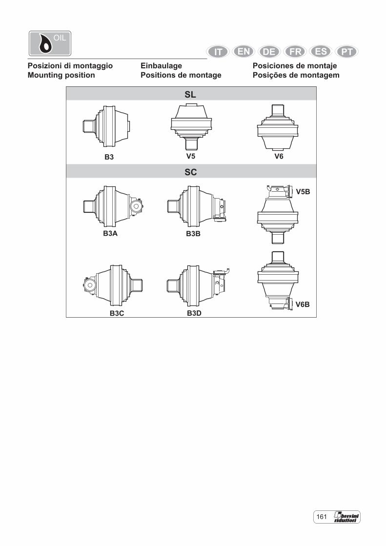
161
Posizioni di montaggioMounting position
Posiciones de montajePosições de montagem
SC
SL
B3
B3D
B3B
V5
B3C
B3A
V6
V6B
V5B
EinbaulagePositions de montage
OIL