Embed Size (px)
Citation preview

Faculté des Sciences Appliquées Département d’Architecture, Géologie, Environnement & Constructions
Structural Engineering
SAFIR MANUAL
Materials SILCON_ETC and CALCON_ETC
September 2011
Thomas GERNAY Jean-Marc FRANSSEN
Université de Liège – ArGEnCo – Structural Engineering Institut de Mécanique et Génie Civil Chemin des chevreuils, 1 - 4000 Liège 1 – Belgique Sart Tilman – Bâtiment B52 - Parking P52 www.argenco.ulg.ac.be
Tél.: +32 (0)4 366.92.65 Fax: +32 (0)4 366.95.34 E-mail : [email protected] +32 (0)4 366.92.45 [email protected]

TABLE OF CONTENTS
I. INTRODUCTION .................................................................................................................................... 3
I.1. NOMENCLATURE ....................................................................................................................................................... 4
I.2. USER INPUT .............................................................................................................................................................. 5
I.2.1. User input for thermal analysis ................................................................................................................... 5
I.2.2. User input for mechanical analysis ............................................................................................................. 5
I.3. INPUT OF THE MATERIAL SUBROUTINES .......................................................................................................................... 6
I.4. OUTPUT OF THE MATERIAL SUBROUTINES ....................................................................................................................... 6
II. DESCRIPTION OF THE MATERIAL LAW .................................................................................................. 7
II.1. THERMAL PROPERTIES ............................................................................................................................................ 7
II.2. MECHANICAL PROPERTIES....................................................................................................................................... 7
II.2.1. General procedure....................................................................................................................................... 7
II.2.2. Concrete in compression ............................................................................................................................. 9
II.2.3. Concrete in tension .................................................................................................................................... 12
II.2.4. Evolution law of the material properties................................................................................................... 14
III. VALIDATION TESTS ............................................................................................................................. 17
III.1. INSTANTANEOUS STRESS-STRAIN CURVES ................................................................................................................. 17
III.2. TRANSIENT TEST CURVES ...................................................................................................................................... 18
III.3. TRANSIENT CREEP STRAIN ..................................................................................................................................... 19
III.4. TESTS ON STRUCTURAL ELEMENTS .......................................................................................................................... 19

T. Gernay - ULg 3
I. INTRODUCTION
This document describes the material models SILCON_ETC and CALCON_ETC, developed at University of Liege and implemented in the software SAFIR. The material models SILCON_ETC and CALCON_ETC are based on the Explicit Transient Creep (ETC) constitutive model for concrete at elevated temperature, developed by the authors of this document.
The SAFIR materials SILCON_ETC and CALCON_ETC are based on the Explicit
Transient Creep Eurocode constitutive model (ETC) for siliceous and calcareous
concrete at elevated temperature.
The ETC model is a uniaxial material model for concrete.
The ETC model is based on the concrete model of Eurocode EN1992-1-2 (EC2),
except that in the ETC model the transient creep strain is treated by an explicit term
in the strain decomposition whereas in the EC2 model the effects of transient creep
strain are incorporated implicitly in the mechanical strain term. The variation of
compressive strength and tensile strength with temperature, as well as the thermal
properties, are taken from EN1992-1-2.
The references for the ETC concrete model are the following:
T. Gernay, “Effect of Transient Creep Strain Model on the Behavior of Concrete Columns Subjected to Heating and Cooling”, Fire Technology, accepted for publication, http://www.springerlink.com/content/3362rp1hv5355462/fulltext.pdf T. Gernay, J-M Franssen, “A Comparison Between Explicit and Implicit Modelling of Transient Creep Strain in Concrete Uniaxial Constitutive Relationships”, Proceedings of the Fire and
Materials 2011 Conference, San Francisco, pp. 405-416, 2011. http://hdl.handle.net/2268/76564
T. Gernay, J-M Franssen, “Consideration of Transient Creep in the Eurocode Constitutive Model for Concrete in the Fire situation”, Proceedings of the Sixth International Conference Structures in
Fire, Michigan State University, pp. 784-791, 2010. http://hdl.handle.net/2268/18295

Materials SILCON_ETC and CALCON_ETC - SAFIR
I.1. Nomenclature
T Temperature
Tmax Maximum temperature in the history of the point
ν Poisson ratio
α Parameter for thermal conductivity
k Thermal conductivity
σ Stress (uniaxial)
totε Total strain (uniaxial)
resε Residual strain
thε Thermal strain
trε Transient creep strain
σε Instantaneous stress-dependent strain
pε Plastic strain
elε Elastic strain
1,EC2cε Peak stress strain of Eurocode 2
1,ENVcε Peak stress strain of ENV (minimum value)
1,ETCcε Peak stress strain of ETC model
0,EC2cε Strain to 0 stress of Eurocode 2
0,ETCcε Strain to 0 stress of ETC model
fck Compressive strength at 20°C
fc,T Compressive strength (temperature-dependent)
ftk Tensile strength at 20°C
ft,T Tensile strength (temperature-dependent)
tE Tangent modulus
( )Tφ Transient creep function
E0,ETC
Elastic modulus of the ETC model

T. Gernay - ULg 5
I.2. User input
I.2.1. User input for thermal analysis If CMAT(NM) = SILCON_ETC , CALCON_ETC - 6 parameters are required (1 line only)
PARACOLD(3,NM) Specific mass [kg/m³] PARACOLD(5,NM) Moisture content [kg/m³] PARACOLD(6,NM) Convection coefficient on hot surfaces [W/m²K] PARACOLD(7,NM) Convection coefficient on cold surfaces [W/m²K] PARACOLD(8,NM) Relative emissivity [-] PARACOLD(4,NM) Parameter for thermal conductivity, α [-] Note: according to clause 3.3.3 of EN-1992-1-2, the thermal conductivity can be chosen between lower and upper limit values. The parameter α allows any intermediate value to be taken
according to ( ) ( ) ( ) ( )( )lower upper lowerk T k T k T k Tα= + − with [ ]0,1α ∈ .
I.2.2. User input for mechanical analysis If CMAT(NM) = SILCON_ETC , CALCON_ETC - 3 parameters are required (1 line only)
PARACOLD(2,NM) Poisson ratio ν [-] PARACOLD(3,NM) Compressive strength fck [N/m²] PARACOLD(4,NM) Tensile strength ftk [N/m²]

Materials SILCON_ETC and CALCON_ETC - SAFIR
I.3. Input of the material subroutines
The input parameters are:
� The current temperature at the integration point T
� The maximum temperature at the integration point Tmax
� The total strain at the current iteration ( )itotε
� Possibly, the residual strain at the current iteration ( )iresε
� The evolution laws of the material properties with temperature:
o Compressive strength fc,T
o Tensile strength ft,T
o Strain to 0 stress according to EC2 0,EC2cε
o Strain to peak stress according to EC2 1, 2c ECε
o Strain to peak stress according to ENV (min value) 1,c ENVε
o Thermal strain thε
Moreover, the routine keeps the values of some parameters from one step to another because they will
be used:
� The plastic strain at the previous (converged) time step ( 1)spε −
� The transient creep strain at the previous (converged) time step ( 1)strε −
� The stress at the previous (converged) time step ( )1sσ −
I.4. Output of the material subroutines
The output parameters are:
� The thermal strain ( )sthε
� The transient creep strain ( )strε
� The plastic strain ( )spε
� The stress ( )sσ
� The tangent modulus ( )stE

T. Gernay - ULg 7
II. DESCRIPTION OF THE MATERIAL LAW
II.1. Thermal properties
The thermal models for the materials SILCON_ETC (siliceous concrete) and CALCON_ETC (carbonate concrete) are taken from EN1992-1-2. The routine implemented in SAFIR for the thermal analysis with material SILCON_ETC is exactly the same as the routine with material SILCONCEC2, and CALCON_ETC is the same as CALCONCEC2.
II.2. Mechanical properties
II.2.1. General procedure The general procedure of the finite elements calculation method implemented in the non linear
software SAFIR is schematized in Figure 1. The following notation has been used: extf is the vector of
the external nodal forces at a particular moment, f∆ is a given increment of force between step (s-1)
and step (s), T is the temperature (which has been calculated for every time step before the beginning
of the mechanical calculation), ( )ir is the residual force after (i) rounds of iteration, intf
is the vector
of the internal forces, u∆ is the increment of displacement corresponding to f∆ , ( )iK is the stiffness
matrix, B is the matrix linking deformations and nodal displacements and tD is the tangent stiffness
matrix of the non linear material law. In the particular case of the ETC concrete model that is explained
here, as it is a uniaxial material model, some notation could be simplified in scalar notation.
The thermal strain is calculated at the beginning of each time step, as a function of the temperature.
This thermal strain does not vary during a time step.
The transient creep strain is also calculated at the beginning of each time step. As the stress at the
equilibrium at the end of step (s) is not known yet when the transient creep strain is calculated, it was
decided to calculate the transient creep strain as a function of the stress at the previous (converged)
time step. The transient creep strain calculation takes into account the stress-temperature history.
Between step (s) and step (s-1), there is an increment in transient creep strain if and only if the three
following conditions are fulfilled:
i. The temperature has increased between step (s) and step (s-1)
ii. The (converged) stress at time step (s-1) is a compressive stress
iii. The tangent modulus of the material is positive, i.e., the material is in the ascending branch of
the stress-strain relationship
In this case, the increment in transient creep strain is calculated as:
( ) ( )( 1)
( ) ( 1)s
s str
ck
T Tf
σε φ φ−
−
∆ = −
where ( 1)sσ − is the compressive stress at the previous time step, ckf is the compressive strength at
20°C and ( )Tφ is a temperature-dependent function. The function ( )Tφ is calculated as:

Materials SILCON_ETC and CALCON_ETC - SAFIR
( ) ( )( )
1, 2 1,2
3c EC c ENV
c ck
Tf f
ε εφ =
−
If the temperature has decreased or remained constant between step (s) and step (s-1), there is no
increment in transient creep strain. Similarly, if the material is subjected to tension or if the material
exhibits its softening behavior after the peak stress in compression, it has been assumed that there is
no increment in transient creep strain. As the function ( )Tφ is growing with temperature, the
transient creep term can only increase. The increment of transient creep strain is the same for loading
and unloading as long as the stress is in compression.
Figure 1 : Flow chart of the implementation of the ETC concrete model in SAFIR
ETC
ETC
Convergence?
Yes ( ) ( )s iσ σ=
( ) ( -1)ext exts sf f f= +∆
( ) datasT =
iter = 0
( ) (s)sth
f Tε
=
,( ) ( -1) ( )s s str f Tε σ
=
( ) ( -1)ext int
i ir f f= −-1
( ) ( -1) ( )∆ =i i iu K r
( ) ( -1) ( )tot tot= +i i iu u u∆ ∆ ∆
( ) ( )tot∆ i iB uε = ∆
( )( ) itt
V
i B D B dVK = ∫
( )( )int
it
V
i B dVf σ= ∫
STEP = STEP +1
iter = iter + 1
MATERIAL LAW
,( ) ( ) ( )i i sf Tσε σ
=
,( ) ( )i i
tDσ→
No
( ) ( ) ( ) ( )i i s stot trthσε ε ε ε= − −

T. Gernay - ULg 9
After calculation of the thermal strain and the transient creep strain, it is possible to calculate the
instantaneous stress-dependent strain by the following equation:
( )tot tr resthσε ε ε ε ε= − − −
This equation is the same as Eq. 4.15 of EN1992-1-2 except that the basic creep strain has not been
taken into account in the ETC concrete model.
II.2.2. Concrete in compression The ETC relationship is written in terms of the instantaneous stress-dependent strain. The ETC stress-strain relationship is made of a nonlinear ascending branch and a descending branch made of two curves, each of them being a third order function of the strain.
Figure 2 : ETC stress-strain relationship in compression
The ascending branch is characterized by the compressive strength cf , and the strain at compressive
strength 1,ETCcε for the ETC relationship. The equation that gives the stress σ and the tangent
modulus are, for 1,ETCcσε ε≤ :
( )( )2
1,ETC 1,ETC
2( )
( ) 1 ( )c
c c
f TT T
σ
σ
εσε ε ε
=+
( )( )
2
1,ETC22
1,ETC 1,ETC
12
1
ct c
c c
E fσ
σ
ε ε
ε ε ε
−=
+
The ETC constitutive relationship has a generic form that is similar to the EC2 constitutive
relationship, but the EC2 model is written in terms of the mechanical strain.
The strain at compressive strength 1,ETCcε is a function of the maximum temperature experienced by
the material Tmax. The relationship between the peak stress strain of the ETC concrete model 1,ETCcε
εσ εc1,ETC
ε*
σ
fc
Edscb

Materials SILCON_ETC and CALCON_ETC - SAFIR
(that does not include transient creep strain) and the peak stress strain of the Eurocode 2 concrete
model 1,EC2cε (that implicitly incorporates transient creep strain) is given by:
( )1,ETC 1, 1,EC22 3c c ENV cε ε ε= +
The value of the modulus at the origin, i.e. the slope of the curve at the origin, cannot be defined by the user. It comes directly from the equation of the stress-strain relationship:
0,ETC 1,ETC2 c cE f ε= .
The descending branch is made of two 3rd order polynomial from point ( 1,ETCcε ; cf ) until point (
0,ETCcε ; 0). The relationship between the strain at 0 stress of the ETC concrete model 0,ETCcε and the
strain at 0 stress of the Eurocode 2 concrete model 0,EC2cε is given by the following equation:
( )0,ETC 0,EC2 1,EC2 1,ETCc c c cε ε ε ε= − − .
The slope of the descending branch at the point where the sign of the concavity of the curve changes is
noted dscbE . This is the slope at the point of transition from the first to the second third order
polynomial. The value of dscbE is given by:
0,ETC 1,ETC
2 cdscb
c c
fE
ε ε=
−
The equation that gives the stress σ and the tangent modulus are:
*1,ETC cc dscbf Eσε ε ε= − −
* *dscbEσ ε=
If ε* ≤ 0 ;
+−=
+−=
1
122
*
**
cdscbt
c
c
fEE
f
f
σ
σσσ
If 0 < ε* ≤ fc/Edscb ;
−=
−+=
1
122
*
**
cdscbt
c
c
fEE
f
f
σ
σσσ
If fc/Edscb < ε* ; 0
0
==
tE
σ
Figure 3 present the (instantaneous) stress-strain curves in compression for the material SILCON_ETC, for temperatures between 20°C and 1000°C.

T. Gernay - ULg 11
Figure 3: ETC concrete model in compression
If concrete has been loaded in compression and, in a later stage, the strain decreases, the unloading is made according to a plasticity model. This means that the path is a linear decrease from the point of maximum compressive strain in the loading curve parallel to the tangent at the origin.
Figure 4 : Unloading in compression – plasticity model
For a material that is first-time heated under compressive stress (i.e. transient test), the ETC concrete model gives the same mechanical strain response as the EC2 concrete model. Indeed in this case, the material develops transient creep strain. In the ETC concrete model, the effects of transient creep strain are added to the instantaneous stress-dependent strain whereas in the EC2 model, the effects of transient creep strain are already incorporated, implicitly in the mechanical strain term (Figure 6). However, the difference between the ETC and the EC2 concrete models is visible when the material is unloaded. In the ETC concrete model, only the elastic strains are recovered whereas in the EC2 model, the transient creep strain is also recovered.
-1.20
-1.00
-0.80
-0.60
-0.40
-0.20
0.00
-3.00E-02 -2.50E-02 -2.00E-02 -1.50E-02 -1.00E-02 -5.00E-03 0.00E+00
fc/fc
k
eps
ETC model at 20 C
200 C
400 C
600 C
800 C
1000 C
σ
εσ

Materials SILCON_ETC and CALCON_ETC - SAFIR
Figure 5 : Concrete behavior at 500°C
For a material that is loaded at (constant) elevated temperature, the mechanical strain response of the ETC and the EC2 models is different. Indeed in this case, no transient creep strain develops in the material so the mechanical strain response of the ETC model is the same as the instantaneous stress-strain response. However, as the effects of transient creep strain are incorporated implicitly in the EC2 model, the response of the EC2 model in case of instantaneous stress-strain test is the same as in case of transient test.
II.2.3. Concrete in tension The behaviour of concrete in tension is described by a stress-strain relationship. This means that neither the opening of individual cracks nor the spacing between different cracks is present in the model. The cracks are said to be « smeared » along the length of the elements. The stress-strain relationship is made of a second order ascending branch and a descending branch made of two curves, each of them being a third order function of the strain.
Figure 6 : ETC stress-strain relationship in tension
0
0.2
0.4
0.6
0.8
1
0 0.005 0.01 0.015 0.02 0.025
No
rmal
ized
str
ess
[fcT
/fc]
Strain
Instantaneous stress-strain
Mechanical stress-strain
Unloading in EC2 model
Unloading in ETC model
ε*
Edscb
εu
E0,ETC
ft
σ
εσ

T. Gernay - ULg 13
The ascending branch is characterized by the tensile strength tf , and the modulus at the origin
0,ETC.E The equation that gives the stress σ and the tangent modulus are, for uσε ε≤ :
0,ETC
2 tu
f
Eε =
0,ETC0,ETC 1
4 t
EE
fσ
σε
σ ε
−
=
0,ETC0,ETC 1
2tt
EE E
fσε
−
=
The descending branch is characterized by the point ( uε ; tf ), by the slope of the descending branch
at the point where the sign of the concavity of the curve changes dscbE . The value of dscbE in tension is
the same as the value in compression. The equation that gives the stress σ and the tangent modulus are:
*u t dscbf Eσε ε ε= − −
* *dscbEσ ε=
If ε* ≤ 0 ;
+−=
+−=
1
122
*
**
tdscbt
t
t
fEE
f
f
σ
σσσ
If 0 < ε* ≤ ft/Edscb ;
−=
−+=
1
122
*
**
tdscbt
t
t
fEE
f
f
σ
σσσ
If ft/Edscb < ε* ; 0
0
==
tE
σ
Figure 7 present the (instantaneous) stress-strain curves in tension for the material SILCON_ETC, for temperatures between 20°C and 500°C. If concrete has been loaded in tension and, in a later stage, the strain decreases, the unloading is made according to a damage model (Figure 8). This means that the path is a linear decrease from the point of maximum tensile strain in the loading curve to the point of origin in the stress-strain diagram plane. The modulus at the origin in tension is the same as the modulus at origin in compression for the same temperature.

Materials SILCON_ETC and CALCON_ETC - SAFIR
Figure 7 : ETC concrete model in tension
Figure 8 : Unloading in tension – damage model
If the tensile strength at room temperature is modified (and the compressive strength is unchanged), the curves of the stress-strain diagram in tension are scaled accordingly, horizontally as well as vertically. The tangents at the origin remain unchanged. If the compressive strength at room temperature is modified (and the tensile strength is unchanged), the tangent at the origin is modified proportionally and the ductility is modified proportionally to 1/fc.
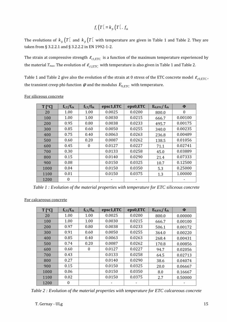
II.2.4. Evolution law of the material properties During heating, the compressive strength fc(T) of concrete that is at temperature T is calculated according to :
( ) ( ) .c fc ckf T k T f=
During heating, the tensile strength ft(T) of concrete that is at temperature T is calculated according to:
0.00
0.20
0.40
0.60
0.80
1.00
1.20
0.00E+00 5.00E-04 1.00E-03 1.50E-03 2.00E-03 2.50E-03
ft/ft
k
eps
ETC model at 20 C
100 C
200 C
300 C
500 C
σ
εσ
T. Gernay - ULg 15
( ) ( ) .t ft tkf T k T f=
The evolutions of ( )fck T and ( )ftk T with temperature are given in Table 1 and Table 2. They are
taken from § 3.2.2.1 and § 3.2.2.2 in EN 1992-1-2.
The strain at compressive strength 1,ETCcε is a function of the maximum temperature experienced by
the material Tmax. The evolution of 1,ETCcε with temperature is also given in Table 1 and Table 2.
Table 1 and Table 2 give also the evolution of the strain at 0 stress of the ETC concrete model 0,ETCcε ,
the transient creep phi-function φ and the modulus 0,ETCE with temperature.
For siliceous concrete
T [°C] fc,T/fck ft,T/ftk epsc1,ETC eps0,ETC E0,ETC/ fck Φ
20 1.00 1.00 0.0025 0.0200 800.0 0
100 1.00 1.00 0.0030 0.0215 666.7 0.00100
200 0.95 0.80 0.0038 0.0233 495.7 0.00175
300 0.85 0.60 0.0050 0.0255 340.0 0.00235
400 0.75 0.40 0.0063 0.0263 236.8 0.00489
500 0.60 0.20 0.0087 0.0262 138.5 0.01056
600 0.45 0 0.0127 0.0227 71.1 0.02741
700 0.30 0.0133 0.0258 45.0 0.03889
800 0.15 0.0140 0.0290 21.4 0.07333
900 0.08 0.0150 0.0325 10.7 0.12500
1000 0.04 0.0150 0.0350 5.3 0.25000
1100 0.01 0.0150 0.0375 1.3 1.00000
1200 0 - - -
Table 1 : Evolution of the material properties with temperature for ETC siliceous concrete
For calcareous concrete
T [°C] fc,T/fck ft,T/ftk epsc1,ETC eps0,ETC E0,ETC/ fck Φ
20 1.00 1.00 0.0025 0.0200 800.0 0.00000 100 1.00 1.00 0.0030 0.0215 666.7 0.00100 200 0.97 0.80 0.0038 0.0233 506.1 0.00172 300 0.91 0.60 0.0050 0.0255 364.0 0.00220 400 0.85 0.40 0.0063 0.0263 268.4 0.00431 500 0.74 0.20 0.0087 0.0262 170.8 0.00856 600 0.60 0 0.0127 0.0227 94.7 0.02056 700 0.43 0.0133 0.0258 64.5 0.02713 800 0.27 0.0140 0.0290 38.6 0.04074 900 0.15 0.0150 0.0325 20.0 0.06667
1000 0.06 0.0150 0.0350 8.0 0.16667 1100 0.02 0.0150 0.0375 2.7 0.50000 1200 0 - - -
Table 2 : Evolution of the material properties with temperature for ETC calcareous concrete

Materials SILCON_ETC and CALCON_ETC - SAFIR
Figure 9 shows the thermal strain as a function of temperature. A residual thermal expansion or shrinkage has been considered when the concrete is back to ambient temperature. The value of the residual value is a function of the maximum temperature and is given in Table 3, taken from experimental tests made by Schneider in 1979. Negative values indicate residual shortening whereas positive values indicate residual expansion.
Figure 9 : Thermal strain implemented in the ETC concrete model
Tmax [°C] εresidual (20°C) [10-3] 20 0 300 -0,58 400 -0,29 600 1,71 800 3,29 ≥ 900 5,00
Table 3 : Residual thermal expansion of concrete implemented in the ETC concrete model
-3.0E-03
0.0E+00
3.0E-03
6.0E-03
9.0E-03
1.2E-02
1.5E-02
0 200 400 600 800 1000
Ep
s,th
Temperature [ C]
Eps,th
Cooling from 800 C
Cooling from 300 C

T. Gernay - ULg 17
III. VALIDATION TESTS
The subroutine SILCON_ETC implemented in SAFIR is tested on a “structure” made of one single BEAM finite element. The cross section of the BEAM finite element is made of 4 fibers that have all the same temperature. All the results presented here have been obtained with the software SAFIR developed at the University of Liege, version 2011.b.0.
III.1. Instantaneous stress-strain curves
The element is first heated and then loaded while the temperature remains constant.
Figure 10 : ETC concrete model in compression
Figure 11 : ETC concrete model in tension
-1.20
-1.00
-0.80
-0.60
-0.40
-0.20
0.00
-0.0300 -0.0250 -0.0200 -0.0150 -0.0100 -0.0050 0.0000
Ad
im. s
tres
s σ
/fck
[-]
Mechanical strain [-]
20 C
100 C
200 C
300 C
400 C
500 C
600 C
0.00
0.20
0.40
0.60
0.80
1.00
0.0000 0.0005 0.0010 0.0015 0.0020 0.0025
Ad
im. s
tres
s σ
/ftk
[-]
Mechanical strain [-]
20 C
200 C
400 C

Materials SILCON_ETC and CALCON_ETC - SAFIR
Figure 12 : Transition zone between tension and compression
III.2. Transient test curves
The transient test curve at a given temperature is obtained by the following process: the element is loaded to a certain stress level; then it is heated to the requested temperature; the process is repeated several times for different load levels. Each transient test curve is thus the result of numerous simulations varying by the stress level that is applied before heating.
Figure 13 : Transient test curves of the ETC model
-0.20
-0.15
-0.10
-0.05
0.00
0.05
0.10
-0.0005 0.0000 0.0005 0.0010 0.0015
Ad
im. s
tres
s σ
/fck
[-]
Mechanical strain [-]
300 C
-1.20
-1.00
-0.80
-0.60
-0.40
-0.20
0.00
-0.0300 -0.0250 -0.0200 -0.0150 -0.0100 -0.0050 0.0000
Ad
im. s
tres
s σ
/fck
[-]
Mechanical strain [-]
200 C
300 C
400 C
500 C
600 C
700 C
800 C

T. Gernay - ULg 19
III.3. Transient creep strain
The transient creep strain curves are obtained by difference between the mechanical strain curves and the instantaneous stress-strain curves.
Figure 14 : Transient creep strain
III.4. Tests on structural elements
For the validation of the ETC concrete model on structural elements, please report to the following publications:
1. T. Gernay, “Effect of Transient Creep Strain Model on the Behavior of Concrete Columns Subjected to Heating and Cooling”, Fire Technology, accepted for publication, http://www.springerlink.com/content/3362rp1hv5355462/fulltext.pdf
2. T. Gernay, J-M Franssen, “A Comparison Between Explicit and Implicit Modelling of Transient Creep Strain in Concrete Uniaxial Constitutive Relationships”, Proceedings of the Fire and
Materials 2011 Conference, San Francisco, pp. 405-416, 2011. http://hdl.handle.net/2268/76564
3. T. Gernay, J-M Franssen, “Consideration of Transient Creep in the Eurocode Constitutive Model
for Concrete in the Fire situation”, Proceedings of the Sixth International Conference Structures
in Fire, Michigan State University, pp. 784-791, 2010. http://hdl.handle.net/2268/18295
-0.0100
-0.0090
-0.0080
-0.0070
-0.0060
-0.0050
-0.0040
-0.0030
-0.0020
-0.0010
0.0000
0 100 200 300 400 500 600 700 800
Tra
nsi
ent c
reep
str
ain
[-]
Temperature [ C]
Stress level 0.167
Stress level 0.20
Stress level 0.33
Stress level 0.50