Embed Size (px)
DESCRIPTION
saravel cooling tower selection
Citation preview
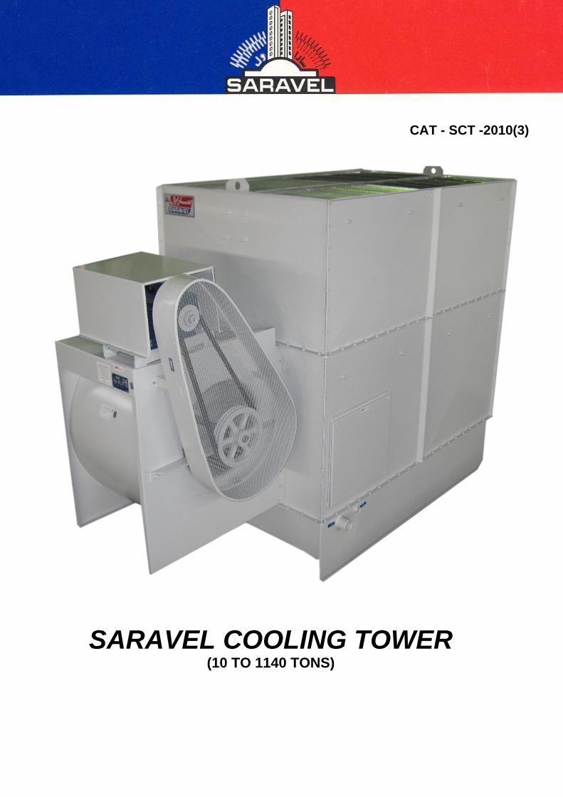
CAT - SCT -2010(3)
SARAVEL COOLING TOWER (10 TO 1140 TONS)

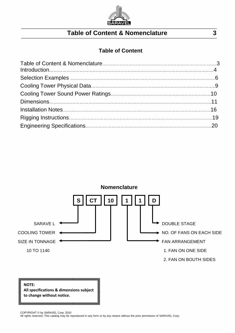
Table of Content & Nomenclature 3
Table of Content
Table of Content & Nomenclature………………………………………………………………….…3
Introduction……………………………………………………………………………………………….…..4
Selection Examples …………………………………………………………………………………….…6
Cooling Tower Physical Data…………………………………………………………………………..9
Cooling Tower Sound Power Ratings……………………………………………………………10
Dimensions………………………………………………………………………………………………….11
Installation Notes…………………………………………………………………………………………16
Rigging Instructions………………………………………………………………………………………19
Engineering Specifications……………………………………………………………………………20
Nomenclature
SARAVE L DOUBLE STAGE
COOLING TOWER NO. OF FANS ON EACH SIDE
SIZE IN TONNAGE FAN ARRANGEMENT
10 TO 1140 1. FAN ON ONE SIDE
2. FAN ON BOUTH SIDES
COPYRIGHT © by SARAVEL Corp. 2010 All rights reserved. This catalog may be reproduced in any form or by any means without the prior permission of SARAVEL Corp.
S CT 10 1 1 D
NOTE: All specifications & dimensions subject to change without notice.
4 Introduction INTRODUCTION SARAVEL cooling towers are Non-Clogging, forced draft, Counter flow, splash type cooling towers designed for a multitude of refrigeration, air conditioning, and industrial process cooling applications. Among the numerous applications are petrochemical, pulp and paper, injection mold cooling, and dairy production industrial.
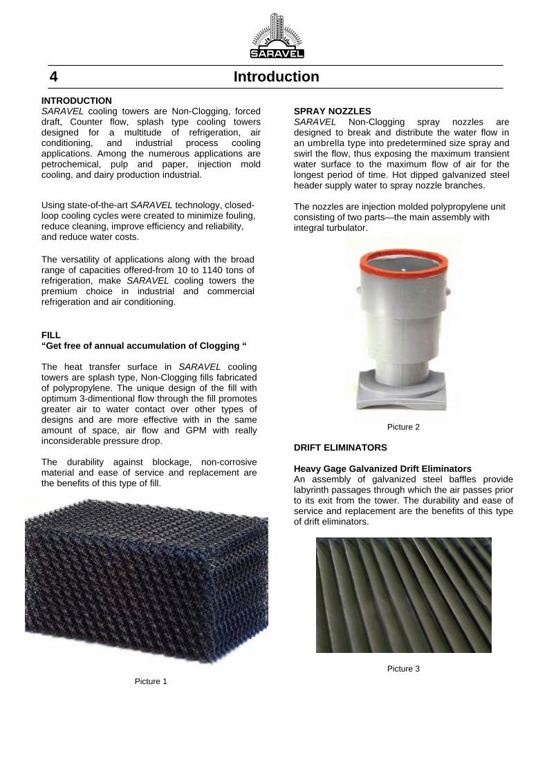
Using state-of-the-art SARAVEL technology, closed-loop cooling cycles were created to minimize fouling, reduce cleaning, improve efficiency and reliability, and reduce water costs. The versatility of applications along with the broad range of capacities offered-from 10 to 1140 tons of refrigeration, make SARAVEL cooling towers the premium choice in industrial and commercial refrigeration and air conditioning. FILL “Get free of annual accumulation of Clogging “ The heat transfer surface in SARAVEL cooling towers are splash type, Non-Clogging fills fabricated of polypropylene. The unique design of the fill with optimum 3-dimentional flow through the fill promotes greater air to water contact over other types of designs and are more effective with in the same amount of space, air flow and GPM with really inconsiderable pressure drop. The durability against blockage, non-corrosive material and ease of service and replacement are the benefits of this type of fill.
Picture 1
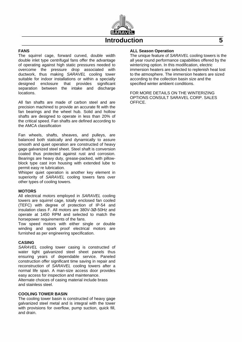
SPRAY NOZZLES SARAVEL Non-Clogging spray nozzles are designed to break and distribute the water flow in an umbrella type into predetermined size spray and swirl the flow, thus exposing the maximum transient water surface to the maximum flow of air for the longest period of time. Hot dipped galvanized steel header supply water to spray nozzle branches. The nozzles are injection molded polypropylene unit consisting of two parts—the main assembly with integral turbulator.
Picture 2
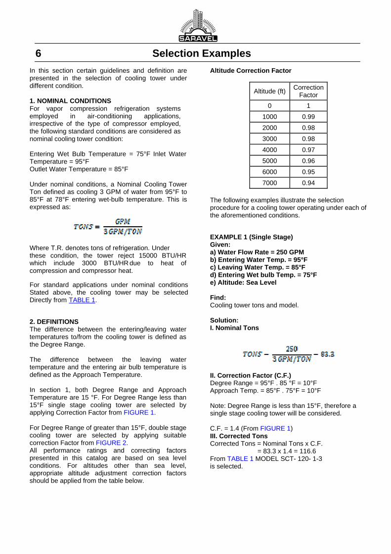
DRIFT ELIMINATORS Heavy Gage Galvanized Drift Eliminators An assembly of galvanized steel baffles provide labyrinth passages through which the air passes prior to its exit from the tower. The durability and ease of service and replacement are the benefits of this type of drift eliminators.
Picture 3
Introduction 5 FANS The squirrel cage, forward curved, double width double inlet type centrifugal fans offer the advantage of operating against high static pressures needed to overcome the pressure drop associated with ductwork, thus making SARAVEL cooling tower suitable for indoor installations or within a specially designed enclosure that provides significant separation between the intake and discharge locations. All fan shafts are made of carbon steel and are precision machined to provide an accurate fit with the fan bearings and the wheel hub. Solid and hollow shafts are designed to operate in less than 20% of the critical speed. Fan shafts are defined according to the AMCA classification Fan wheels, shafts, sheaves, and pulleys, are balanced both statically and dynamically to assure smooth and quiet operation are constructed of heavy gage galvanized steel sheet. Steel shaft is conversion coated thus protected against rust and corrosion. Bearings are heavy duty, grease-packed, with pillow-block type cast iron housing with extended lube to permit easy re lubrication. Whisper quiet operation is another key element in superiority of SARAVEL cooling towers fans over other types of cooling towers. MOTORS All electrical motors employed in SARAVEL cooling towers are squirrel cage, totally enclosed fan cooled (TEFC) with degree of protection of IP-54 and insulation class F. All motors are 380V-3Ø-50Hz and operate at 1450 RPM and selected to match the horsepower requirements of the fans. Tow speed motors with either single or double winding and spark proof electrical motors are furnished as per engineering specification. CASING SARAVEL cooling tower casing is constructed of water tight galvanized steel sheet panels thus ensuring years of dependable service. Paneled construction offer significant time saving in repair and reconstruction of SARAVEL cooling towers after a normal life span. A man-size access door provides easy access for inspection and maintenance. Alternate choices of casing material include brass and stainless steel. COOLING TOWER BASIN The cooling tower basin is constructed of heavy gage galvanized steel metal and is integral with the tower with provisions for overflow, pump suction, quick fill, and drain.
ALL Season Operation The unique feature of SARAVEL cooling towers is the all year round performance capabilities offered by the winterizing option. In this modification, electric immersion heaters are selected to replenish heat lost to the atmosphere. The immersion heaters are sized according to the collection basin size and the specified winter ambient conditions. FOR MORE DETAILS ON THE WINTERIZING OPTIONS CONSULT SARAVEL CORP. SALES OFFICE.
6 Selection Examples In this section certain guidelines and definition are presented in the selection of cooling tower under different condition. 1. NOMINAL CONDITIONS For vapor compression refrigeration systems employed in air-conditioning applications, irrespective of the type of compressor employed, the following standard conditions are considered as nominal cooling tower condition: Entering Wet Bulb Temperature = 75°F Inlet Water Temperature = 95°F Outlet Water Temperature = 85°F Under nominal conditions, a Nominal Cooling Tower Ton defined as cooling 3 GPM of water from 95°F to 85°F at 78°F entering wet-bulb temperature. This is expressed as:
Where T.R. denotes tons of refrigeration. Under these condition, the tower reject 15000 BTU/HR which include 3000 BTU/HR due to heat of compression and compressor heat.
For standard applications under nominal conditions Stated above, the cooling tower may be selected Directly from TABLE 1.
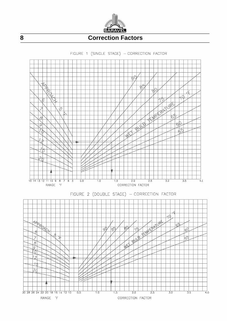
2. DEFINITIONS The difference between the entering/leaving water temperatures to/from the cooling tower is defined as the Degree Range. The difference between the leaving water temperature and the entering air bulb temperature is defined as the Approach Temperature. In section 1, both Degree Range and Approach Temperature are 15 °F. For Degree Range less than 15°F single stage cooling tower are selected by applying Correction Factor from FIGURE 1. For Degree Range of greater than 15°F, double stage cooling tower are selected by applying suitable correction Factor from FIGURE 2. All performance ratings and correcting factors presented in this catalog are based on sea level conditions. For altitudes other than sea level, appropriate altitude adjustment correction factors should be applied from the table below.
Altitude Correction Factor
Altitude (ft) Correction
Factor
0 1
1000 0.99
2000 0.98
3000 0.98
4000 0.97
5000 0.96
6000 0.95
7000 0.94
The following examples illustrate the selection procedure for a cooling tower operating under each of the aforementioned conditions.
EXAMPLE 1 (Single Stage) Given: a) Water Flow Rate = 250 GPM b) Entering Water Temp. = 95°F c) Leaving Water Temp. = 85°F d) Entering Wet bulb Temp. = 75°F e) Altitude: Sea Level Find: Cooling tower tons and model. Solution: I. Nominal Tons
II. Correction Factor (C.F.) Degree Range = 95°F . 85 °F = 10°F Approach Temp. = 85°F . 75°F = 10°F Note: Degree Range is less than 15°F, therefore a single stage cooling tower will be considered. C.F. = 1.4 (From FIGURE 1) III. Corrected Tons Corrected Tons = Nominal Tons x C.F. = 83.3 x 1.4 = 116.6 From TABLE 1 MODEL SCT- 120- 1-3 is selected.

Selection Examples 7
EXAMPLE 2 (Double Stage) GIVEN: a) Water Flow Rate = 250 GPM b) Entering Water Temp. = 100°F c) Leaving Water Temp. = 85°F d) Entering Wet bulb Temp. = 70°F e) Altitude: Sea Level Solution: I. Nominal Tons
II. Correction Factor (C.F.) Degree Range = 100°F - 80°F = 20°F Approach Temp. = 80°F - 70°F = 10°F Note: Degree Range is greater than 15°F Therefore a double stage cooling tower will be selected. C.F. = 1.4 (From FIGURE 2) III. Corrected Tons Corrected Tons = Nominal Tons x C.F. = 83.3 x 1.4 = 116.6 From TABLE 1 MODEL SCT-120-1-3 is selected. EXAMPLE 3 (Above Sea Level): With increasing altitudes above the sea level, the enthalpy of the saturated air increases. At a given temperature, there is more enthalpy change per degree charge in altitude than there will be at sea level. This is because the saturation vapor pressure of water remains nearly constant while the barometric pressure decreases, so the water vapor becomes a larger fraction of the total mixture. At altitude, one pound of dry air can hold more water than it can at sea level (1). Appropriate correction factors must be applied before selecting the unit. Given the same conditions as in EXAMPEL 1 and 2, except with the elevation of 4000 FT, the following modifications must be applied to the calculations: Correction Factor From Altitude Correction Factor table C.F. ALT = 0.97 Corrected Tonnage: Nominal Tonnage x C.F. X C.F. ALT
= 83.3 x 1.4 x 0.97 = 113 Tons.
This example illustrates cooling tower performance enhancement at altitude. A cooling tower properly designed for a sea-level location would exhibit added capability if moved to higher elevation. (1) Journal of the Cooling Tower Institute, Vol. 5, No.1, 1984, P. 28
8 Correction Factors

Physical Data 9
Table 1
MODEL NOMINAL TONS
WATER LOAD (GPM)
FLOW (CFM)
Tower Head (ft H2O)
FAN NO.
FAN SIZE (in)
FAN MOTOR NO.
FAN MOTOR (HP)
WIGHT (Kg)
NET OPERATION
SCT 10 ‐ 1 ‐ 1 10 30 2255 22 1 14 1 0.5 240 350
SCT 15 ‐ 1 ‐ 1 15 45 3384 24 1 16 1 1 280 440
SCT 20 ‐ 1 ‐ 1 20 60 4511 22 1 17 1 1.5 330 530
SCT 25 ‐ 1 ‐ 1 25 75 5640 24 1 19 1 1.5 400 650
SCT 30 ‐ 1 ‐ 1 30 90 6769 21 1 22 1 1.5 500 780
SCT 35 ‐ 1 ‐ 1 35 105 7895 22 1 22 1 2 550 900
SCT 40 ‐ 1 ‐ 1 40 120 9024 23 1 22 1 3 590 980
SCT 50 ‐ 1 ‐ 1 50 150 11281 23 1 22 1 5.5 670 1170
SCT 60 ‐ 1 ‐ 1 60 180 13538 24 1 22 1 7.5 830 1590
SCT 75 ‐ 1 ‐ 2 75 225 16921 25 2 22 1 7.5 1210 2310
SCT 90 ‐ 1 ‐ 2 90 270 20306 25 2 22 1 10 1240 2390
SCT 105 ‐ 1 ‐ 2 105 315 23684 25 2 22 1 15 1340 2740
SCT 120 ‐ 1 ‐ 3 120 360 27073 25 3 22 1 7.5
1740 3490 1 3
SCT 140 ‐ 1 ‐ 3 140 420 31578 25 3 22 1 10
1940 3840 1 4
SCT 160 ‐ 1 ‐ 4 160 480 36097 25 4 22 2 7.5 2490 4680
SCT 180 ‐ 1 ‐ 4 180 540 40612 26 4 22 2 10 2550 4950
SCT 220 ‐ 1 ‐ 5 220 660 49637 26 5 22 2 7.5
2990 5780 1 3
SCT 260 ‐ 1 ‐ 6 260 780 58632 25 6 22 3 7.5 3480 6780
SCT 300 ‐ 1 ‐ 7 300 900 67676 26 7 22 3 7.5
4080 7980 1 3
SCT 340 ‐ 1 ‐ 8 340 1020 76710 26 8 22 4 7.5 4570 9070
SCT 340 ‐ 2 ‐ 4 340 1020 76710 26 8 22 4 7.5 4470 8870
SCT 400 ‐ 2 ‐ 5 400 1200 90211 26 10 22 4 7.5
5270 10770 2 3
SCT 450 ‐ 2 ‐ 6 450 1350 101531 25 12 22 6 7.5 6590 12890
SCT 500 ‐ 2 ‐ 6 500 1500 112814 25 12 22 6 7.5 6670 13170
SCT 580 ‐ 2 ‐ 6 580 1740 130833 25 14 22 6 7.5
7570 15170 2 3
SCT 660 ‐ 2 ‐ 8 660 1980 148905 26 16 22 8 7.5 8750 17450
SCT 740 ‐ 2 ‐ 9 740 2220 166963 26 18 22 8 7.5
9750 19550 2 3
SCT 820 ‐ 2 ‐ 10 820 2460 185014 25 20 22 10 7.5 10840 21740
SCT 900 ‐ 2 ‐ 11 900 2700 202951 25 22 22 10 7.5
11740 23640 2 3
SCT 980 ‐ 2 ‐ 12 980 2940 221020 25 24 22 12 7.5 12730 25730
SCT 1060 ‐ 2 ‐ 13 1060 3180 239086 26 26 22 12 7.5
13830 27830 2 3
SCT 1140 ‐ 2 ‐ 14 1140 3420 257149 26 28 22 14 7.5 14720 29820
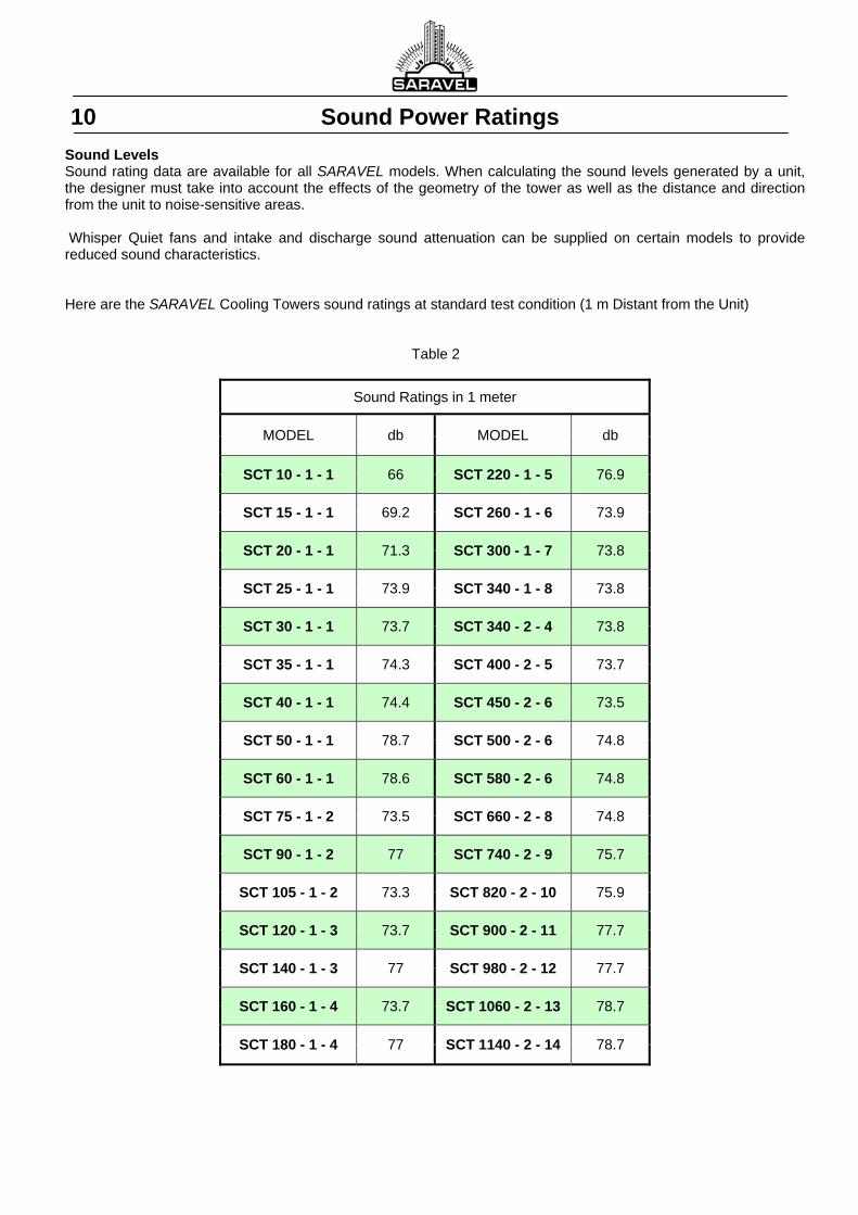
10 Sound Power Ratings Sound Levels Sound rating data are available for all SARAVEL models. When calculating the sound levels generated by a unit, the designer must take into account the effects of the geometry of the tower as well as the distance and direction from the unit to noise-sensitive areas. Whisper Quiet fans and intake and discharge sound attenuation can be supplied on certain models to provide reduced sound characteristics. Here are the SARAVEL Cooling Towers sound ratings at standard test condition (1 m Distant from the Unit)
Table 2
Sound Ratings in 1 meter
MODEL db MODEL db
SCT 10 - 1 - 1 66 SCT 220 - 1 - 5 76.9
SCT 15 - 1 - 1 69.2 SCT 260 - 1 - 6 73.9
SCT 20 - 1 - 1 71.3 SCT 300 - 1 - 7 73.8
SCT 25 - 1 - 1 73.9 SCT 340 - 1 - 8 73.8
SCT 30 - 1 - 1 73.7 SCT 340 - 2 - 4 73.8
SCT 35 - 1 - 1 74.3 SCT 400 - 2 - 5 73.7
SCT 40 - 1 - 1 74.4 SCT 450 - 2 - 6 73.5
SCT 50 - 1 - 1 78.7 SCT 500 - 2 - 6 74.8
SCT 60 - 1 - 1 78.6 SCT 580 - 2 - 6 74.8
SCT 75 - 1 - 2 73.5 SCT 660 - 2 - 8 74.8
SCT 90 - 1 - 2 77 SCT 740 - 2 - 9 75.7
SCT 105 - 1 - 2 73.3 SCT 820 - 2 - 10 75.9
SCT 120 - 1 - 3 73.7 SCT 900 - 2 - 11 77.7
SCT 140 - 1 - 3 77 SCT 980 - 2 - 12 77.7
SCT 160 - 1 - 4 73.7 SCT 1060 - 2 - 13 78.7
SCT 180 - 1 - 4 77 SCT 1140 - 2 - 14 78.7
Dimensions 11
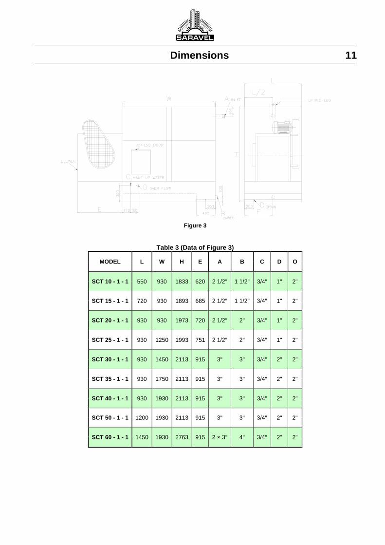
Figure 3
Table 3 (Data of Figure 3)
MODEL L W H E A B C D O
SCT 10 - 1 - 1 550 930 1833 620 2 1/2" 1 1/2" 3/4" 1" 2"
SCT 15 - 1 - 1 720 930 1893 685 2 1/2" 1 1/2" 3/4" 1" 2"
SCT 20 - 1 - 1 930 930 1973 720 2 1/2" 2" 3/4" 1" 2"
SCT 25 - 1 - 1 930 1250 1993 751 2 1/2" 2" 3/4" 1" 2"
SCT 30 - 1 - 1 930 1450 2113 915 3" 3" 3/4" 2" 2"
SCT 35 - 1 - 1 930 1750 2113 915 3" 3" 3/4" 2" 2"
SCT 40 - 1 - 1 930 1930 2113 915 3" 3" 3/4" 2" 2"
SCT 50 - 1 - 1 1200 1930 2113 915 3" 3" 3/4" 2" 2"
SCT 60 - 1 - 1 1450 1930 2763 915 2 × 3" 4" 3/4" 2" 2"
12 Dimensions
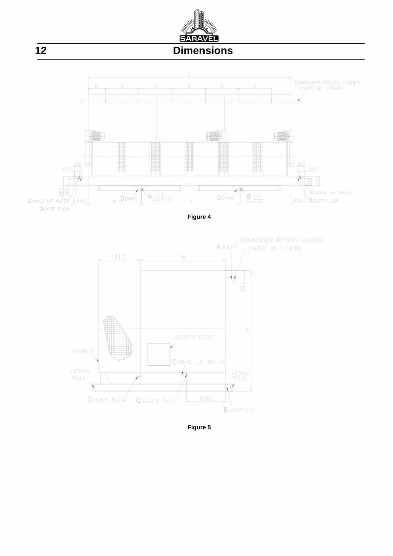
Figure 4
Figure 5
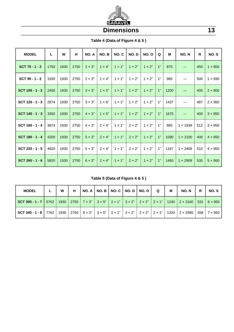
Dimensions 13
Table 4 (Data of Figure 4 & 5 )
Table 5 (Data of Figure 4 & 5 )
MODEL L W H NO. A NO. B NO. C NO. D NO. O Q M NO. N R NO. S
SCT 300 - 1 - 7 6762 1930 2750 7 × 3" 3 × 5" 2 × 1" 3 × 2" 2 × 2" 2 × 1" 1240 2 × 2160 531 6 × 950
SCT 340 - 1 - 8 7762 1930 2750 8 × 3" 3 × 5" 2 × 1" 3 × 2" 2 × 2" 2 × 1" 1320 2 × 2580 558 7 × 950
MODEL L W H NO. A NO. B NO. C NO. D NO. O Q M NO. N R NO. S
SCT 75 - 1 - 2 1750 1930 2750 2 × 3" 1 × 4" 1 × 1" 1 × 2" 1 × 2" 1" 875 --- 450 1 × 850
SCT 90 - 1 - 2 1930 1930 2750 2 × 3" 1 × 4" 1 × 1" 1 × 2" 1 × 2" 1" 965 --- 500 1 × 930
SCT 105 - 1 - 2 2400 1930 2750 3 × 3" 1 × 5" 1 × 1" 1 × 2" 1 × 2" 1" 1200 --- 400 2 × 800
SCT 120 - 1 - 3 2874 1930 2750 3 × 3" 1 × 5" 1 × 1" 1 × 2" 1 × 2" 1" 1437 --- 487 2 × 950
SCT 140 - 1 - 3 3350 1930 2750 4 × 3" 1 × 5" 1 × 1" 1 × 2" 1 × 2" 1" 1675 --- 400 3 × 850
SCT 160 - 1 - 4 3874 1930 2750 4 × 3" 2 × 4" 1 × 1" 2 × 2" 1 × 2" 1" 965 1 × 1939 512 3 × 950
SCT 180 - 1 - 4 4200 1930 2750 5 × 3" 2 × 4" 1 × 1" 2 × 2" 1 × 2" 1" 1090 1 × 2100 400 4 × 850
SCT 220 - 1 - 5 4820 1930 2750 5 × 3" 2 × 4" 1 × 1" 2 × 2" 1 × 2" 1" 1167 1 × 2409 510 4 × 950
SCT 260 - 1 - 6 5820 1930 2750 6 × 3" 2 × 4" 1 × 1" 2 × 2" 1 × 2" 1" 1450 1 × 2909 535 5 × 950
14 Dimensions
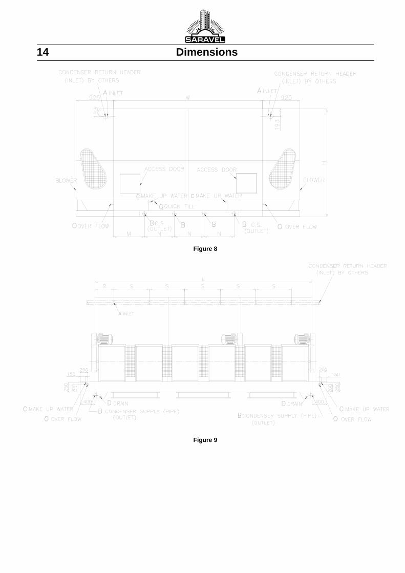
Figure 8
Figure 9
Dimensions 15
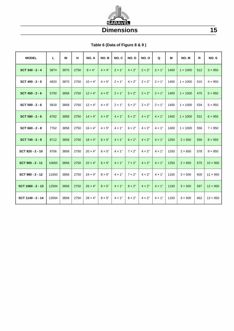
Table 6 (Data of Figure 8 & 9 )
MODEL L W H NO. A NO. B NO. C NO. D NO. O Q M NO. M R NO. S
SCT 340 - 2 - 4 3874 3870 2750 8 × 4" 4 × 4" 2 × 1" 4 × 2" 2 × 2" 2 × 1" 1400 1 × 1000 512 3 × 950
SCT 400 - 2 - 5 4820 3870 2750 10 × 4" 4 × 5" 2 × 1" 4 × 2" 2 × 2" 2 × 1" 1400 1 × 1000 510 4 × 950
SCT 450 - 2 - 6 5700 3858 2750 12 × 4" 4 × 5" 2 × 1" 5 × 2" 2 × 2" 2 × 1" 1400 1 × 1000 475 5 × 950
SCT 500 - 2 - 6 5818 3858 2750 12 × 4" 4 × 5" 2 × 1" 5 × 2" 2 × 2" 2 × 1" 1400 1 × 1000 534 5 × 950
SCT 580 - 2 - 6 6762 3858 2750 14 × 4" 4 × 5" 4 × 1" 5 × 2" 4 × 2" 4 × 1" 1400 1 × 1000 531 6 × 950
SCT 660 - 2 - 8 7762 3858 2750 16 × 4" 4 × 5" 4 × 1" 6 × 2" 4 × 2" 4 × 1" 1400 1 × 1000 556 7 × 950
SCT 740 - 2 - 9 8712 3858 2750 18 × 4" 6 × 5" 4 × 1" 6 × 2" 4 × 2" 4 × 1" 1250 2 × 650 556 8 × 950
SCT 820 - 2 - 10 9706 3858 2750 20 × 4" 6 × 5" 4 × 1" 7 × 2" 4 × 2" 4 × 1" 1250 2 × 650 578 9 × 950
SCT 900 - 2 - 11 10650 3858 2750 22 × 4" 6 × 5" 4 × 1" 7 × 2" 4 × 2" 4 × 1" 1250 2 × 650 575 10 × 950
SCT 980 - 2 - 12 11650 3858 2750 24 × 4" 8 × 5" 4 × 1" 7 × 2" 4 × 2" 4 × 1" 1150 3 × 500 600 11 × 950
SCT 1060 - 2 - 13 12594 3858 2750 26 × 4" 8 × 5" 4 × 1" 8 × 2" 4 × 2" 4 × 1" 1150 3 × 500 597 12 × 950
SCT 1140 - 2 - 14 13594 3858 2750 28 × 4" 8 × 5" 4 × 1" 8 × 2" 4 × 2" 4 × 1" 1150 3 × 500 662 13 × 950

16 Installation Notes LOCATION Cooling towers must be located to ensure an adequate supply of fresh air to the air inlets. When units are located adjacent to building wall or in enclosures, care must be taken to ensure that the warm, saturated discharge air is not deflected and short-circulated back to the air intakes. See FIGURE 13.
In instances where for aesthetic reasons a decorative louver is to be placed around the periphery of the cooling tower, adequate distance between adjacent louver elements and distance from the intake of the cooling tower should be specified to prevent intake air deficiency.
Additionally, each cooling tower should be located and positioned to prevent the introduction of its discharge air into the ventilation systems of the building on which the tower is located or into that of adjacent buildings.
PIPING Piping should be size and installed in accordance with piping practice. In order to prevent over flowing of the tower basin and ensure
satisfactory pump operation at startup, all heat exchangers and as much tower piping as possible should be installed below the operation level of the tower. In addition all piping should be supported separately from the unit through the use of pipe hangers or supports.
If more than one inlet connection is required, balancing valves should be installed to property balance flow to each cooling tower cell. See FIGURE 10 & 11. The use of shut-off valves is dictated by the necessity to isolate units for servicing.
When multiple towers are used on a common system, equalizing lines should be installed between the sumps of the separate units to ensure balanced water level in all units. See FIGURE 12.
Provisions must be envisioned in the installation phase to facilitate drainage of the cooling tower for winter season.
Figure 10 Figure 11
Figure 12
Wrong inlet connection Right inlet connection
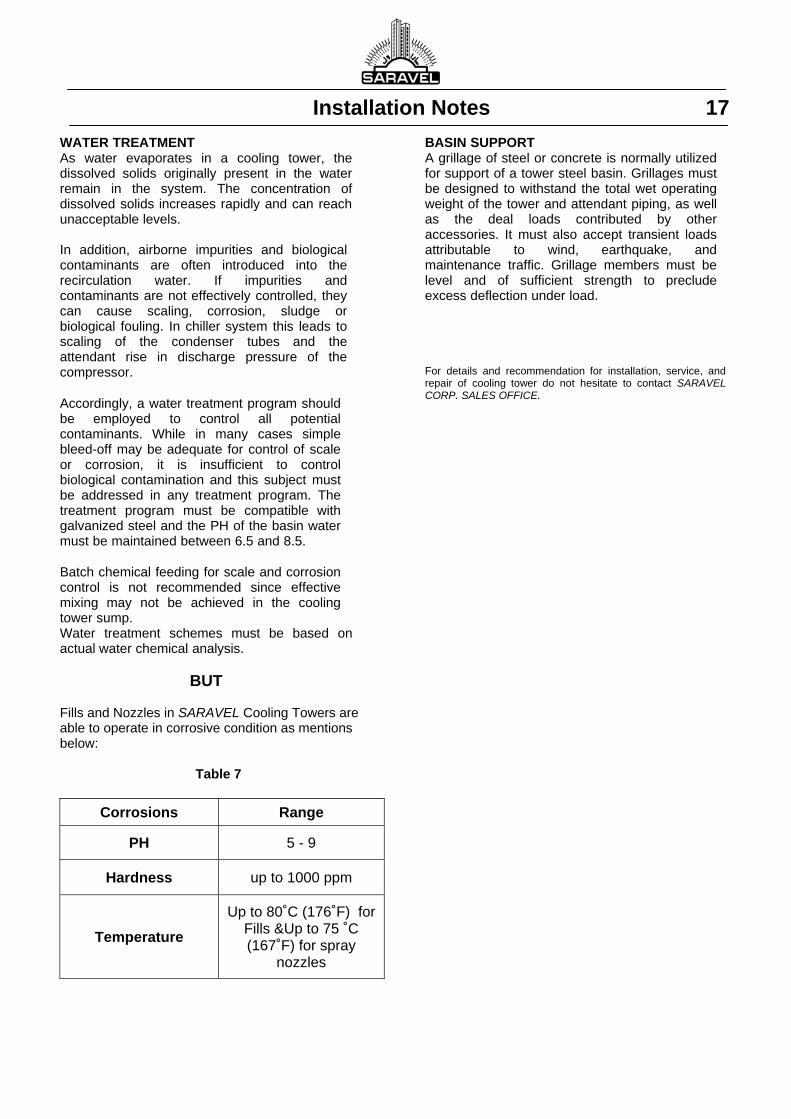
Installation Notes 17 WATER TREATMENT As water evaporates in a cooling tower, the dissolved solids originally present in the water remain in the system. The concentration of dissolved solids increases rapidly and can reach unacceptable levels. In addition, airborne impurities and biological contaminants are often introduced into the recirculation water. If impurities and contaminants are not effectively controlled, they can cause scaling, corrosion, sludge or biological fouling. In chiller system this leads to scaling of the condenser tubes and the attendant rise in discharge pressure of the compressor. Accordingly, a water treatment program should be employed to control all potential contaminants. While in many cases simple bleed-off may be adequate for control of scale or corrosion, it is insufficient to control biological contamination and this subject must be addressed in any treatment program. The treatment program must be compatible with galvanized steel and the PH of the basin water must be maintained between 6.5 and 8.5. Batch chemical feeding for scale and corrosion control is not recommended since effective mixing may not be achieved in the cooling tower sump. Water treatment schemes must be based on actual water chemical analysis.
BUT Fills and Nozzles in SARAVEL Cooling Towers are able to operate in corrosive condition as mentions below:
Table 7
Corrosions Range
PH 5 - 9
Hardness up to 1000 ppm
Temperature
Up to 80˚C (176˚F) for Fills &Up to 75 ˚C (167˚F) for spray
nozzles
BASIN SUPPORT A grillage of steel or concrete is normally utilized for support of a tower steel basin. Grillages must be designed to withstand the total wet operating weight of the tower and attendant piping, as well as the deal loads contributed by other accessories. It must also accept transient loads attributable to wind, earthquake, and maintenance traffic. Grillage members must be level and of sufficient strength to preclude excess deflection under load. For details and recommendation for installation, service, and repair of cooling tower do not hesitate to contact SARAVEL CORP. SALES OFFICE.
Wind
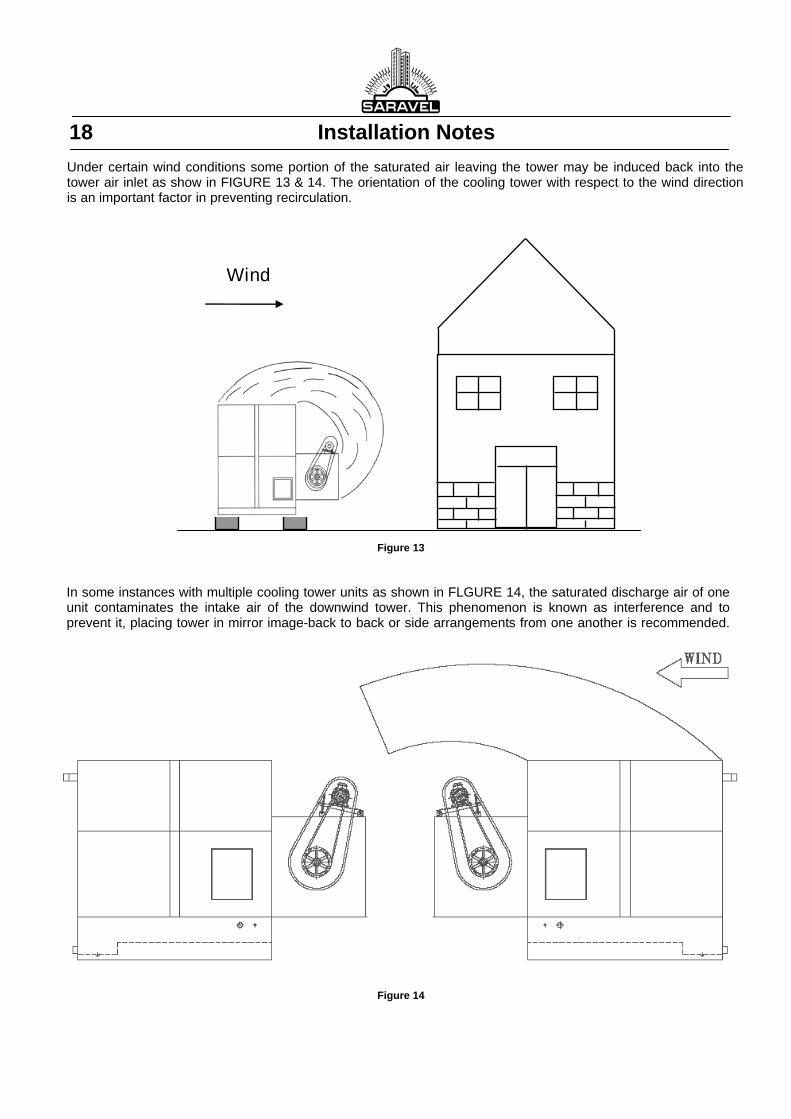
18 Installation Notes Under certain wind conditions some portion of the saturated air leaving the tower may be induced back into the tower air inlet as show in FIGURE 13 & 14. The orientation of the cooling tower with respect to the wind direction is an important factor in preventing recirculation.
Figure 13
In some instances with multiple cooling tower units as shown in FLGURE 14, the saturated discharge air of one unit contaminates the intake air of the downwind tower. This phenomenon is known as interference and to prevent it, placing tower in mirror image-back to back or side arrangements from one another is recommended.
Figure 14

Rigging Instructions 19
Models SCT-10 through SCT-60 are equipped with lifting lugs and may be hoisted according to FIGURE 15. It is recommended to maintain a height of at least 1.5 m between top of a unit to the apex of lifting cables to avoid interference and overloading of the lifting lugs in the wrong direction.
Figure 15
Models SCT –75 through SCT-1140 may be lifted by placing slings through the holes at the base of the unit. FIGURE 16 the spacer bar serves as a stabilizer against unnecessary swinging1 twisting of the unit. Furthermore the hosting cable does not touch the casing to cause damage.
Figure 16
20 Engineering Specifications
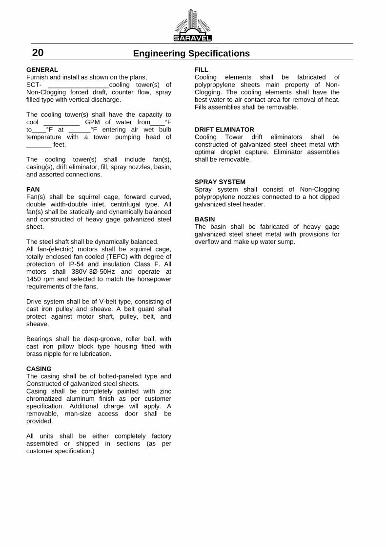
GENERAL Furnish and install as shown on the plans, SCT- _________________cooling tower(s) of Non-Clogging forced draft, counter flow, spray filled type with vertical discharge. The cooling tower(s) shall have the capacity to cool __________ GPM of water from____°F to____°F at ______°F entering air wet bulb temperature with a tower pumping head of _______ feet. The cooling tower(s) shall include fan(s), casing(s), drift eliminator, fill, spray nozzles, basin, and assorted connections. FAN Fan(s) shall be squirrel cage, forward curved, double width-double inlet, centrifugal type. All fan(s) shall be statically and dynamically balanced and constructed of heavy gage galvanized steel sheet. The steel shaft shall be dynamically balanced. All fan-(electric) motors shall be squirrel cage, totally enclosed fan cooled (TEFC) with degree of protection of IP-54 and insulation Class F. All motors shall 380V-3Ø-50Hz and operate at 1450 rpm and selected to match the horsepower requirements of the fans. Drive system shall be of V-belt type, consisting of cast iron pulley and sheave. A belt guard shall protect against motor shaft, pulley, belt, and sheave. Bearings shall be deep-groove, roller ball, with cast iron pillow block type housing fitted with brass nipple for re lubrication. CASING The casing shall be of bolted-paneled type and Constructed of galvanized steel sheets. Casing shall be completely painted with zinc chromatized aluminum finish as per customer specification. Additional charge will apply. A removable, man-size access door shall be provided. All units shall be either completely factory assembled or shipped in sections (as per customer specification.)
FILL Cooling elements shall be fabricated of polypropylene sheets main property of Non-Clogging. The cooling elements shall have the best water to air contact area for removal of heat. Fills assemblies shall be removable. DRIFT ELMINATOR Cooling Tower drift eliminators shall be constructed of galvanized steel sheet metal with optimal droplet capture. Eliminator assemblies shall be removable. SPRAY SYSTEM Spray system shall consist of Non-Clogging polypropylene nozzles connected to a hot dipped galvanized steel header. BASIN The basin shall be fabricated of heavy gage galvanized steel sheet metal with provisions for overflow and make up water sump.
Conversion Factors 21
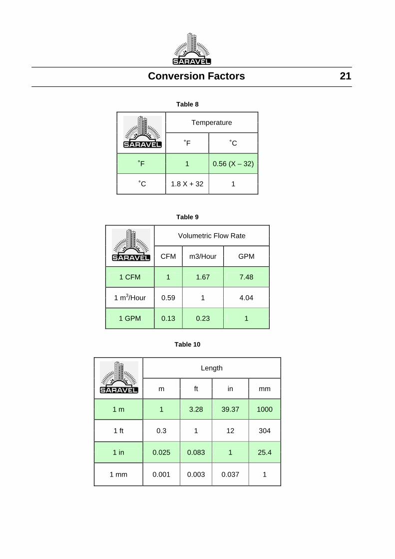
Table 8
Temperature
˚F ˚C
˚F 1 0.56 (X – 32)
˚C 1.8 X + 32 1
Table 9
Table 10
Volumetric Flow Rate
CFM m3/Hour GPM
1 CFM 1 1.67 7.48
1 m3/Hour 0.59 1 4.04
1 GPM 0.13 0.23 1
Length
m ft in mm
1 m 1 3.28 39.37 1000
1 ft 0.3 1 12 304
1 in 0.025 0.083 1 25.4
1 mm 0.001 0.003 0.037 1
SARAVEL CORP.
Feb. 2010
Manufacturer reserves the right to make changes in design and construction, without notice.
(Head Office) No. 43, North Sheikh Bahai Avenue, Tehran 19917, IRAN Tel: (+98‐21) 88046921 (6 lines) Fax: (+98‐21) 88046920
E‐Mail Address: [email protected] Web Site: http://www.Saravel.com