Embed Size (px)
DESCRIPTION
Scenarios for module string tests in CTF3. Next phase - Preliminary schedule. 12 to 16 PETS. 8 PETS. Single PETS. 4 PETS. 2 nd phase (2013-2014) 3 modules to be tested with beam and RF. T0. T0. T1. Beam. ACE, G. Riddone. CTF3. Intrinsic limitations: - PowerPoint PPT Presentation
Citation preview

R. Corsini, Discussion on CTF3+ module string 3/2/20116th CLIC ACE
Scenarios for module string tests in CTF3
Scenarios for module string tests in CTF3
R. Corsini, Discussion on CTF3+ module string 3/2/20116th CLIC ACE
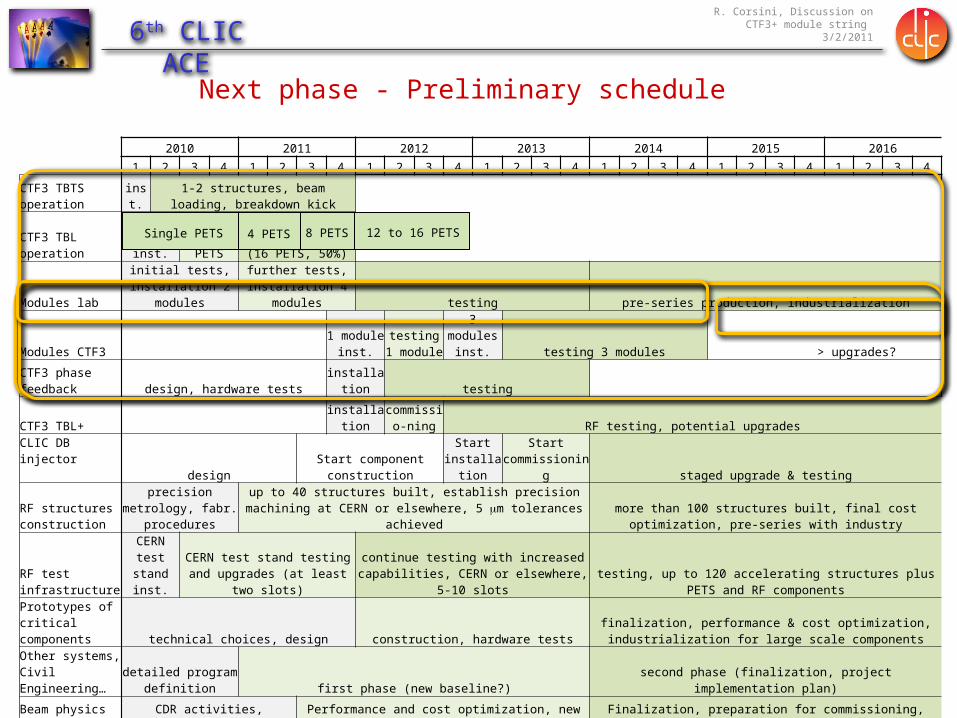
2010 2011 2012 2013 2014 2015 2016
1 2 3 4 1 2 3 4 1 2 3 4 1 2 3 4 1 2 3 4 1 2 3 4 1 2 3 4
CTF3 TBTS operation inst.1-2 structures, beam loading, breakdown
kick
CTF3 TBL operation inst.Deceleratio
n 8 PETSfinal decelerator test
(16 PETS, 50%)
Modules labinitial tests, installation
2 modulesfurther tests,
installation 4 modules testing pre-series production, industrialization
Modules CTF3 1 module
inst.testing 1 module
3 modules inst. testing 3 modules > upgrades?
CTF3 phase feedback design, hardware tests installation testing
CTF3 TBL+ installationcommissio-
ning RF testing, potential upgrades
CLIC DB injectordesign Start component construction
Start installation
Start commissioning staged upgrade & testing
RF structures construction
precision metrology, fabr. procedures
up to 40 structures built, establish precision machining at CERN or elsewhere, 5 mm tolerances achieved
more than 100 structures built, final cost optimization, pre-series with industry
RF test infrastructure
CERN test stand inst.
CERN test stand testing and upgrades (at least two slots)
continue testing with increased capabilities, CERN or elsewhere, 5-10 slots testing, up to 120 accelerating structures plus PETS and RF components
Prototypes of critical components technical choices, design construction, hardware tests
finalization, performance & cost optimization, industrialization for large scale components
Other systems, Civil Engineering…
detailed program definition first phase (new baseline?) second phase (finalization, project implementation plan)
Beam physics studies CDR activities, feasibility studies Performance and cost optimization, new baseline? Finalization, preparation for commissioning, operational scenarios…
Next phase - Preliminary schedule
Single PETS 4 PETS 8 PETS 12 to 16 PETS

R. Corsini, Discussion on CTF3+ module string 3/2/20116th CLIC ACE
T0T1 T0
Beam
2nd phase (2013-2014)3 modules to be tested with beam and RF
ACE, G. Riddone

R. Corsini, Discussion on CTF3+ module string 3/2/20116th CLIC ACE
CTF3
Intrinsic limitations:
• Combined beam current, limited to ~ 30 A (could possibly be increased for shorter pulses)
• Pulse length limited to 140 ns (instead of 240 ns) @ 30 A – alternative: 15 A, < 280 ns
• Total drive beam peak power (at present ~ 3.5 GW – CLIC0 has 48 GW, CLIC 240 GW)
DRIVE BEAM LINAC
CLEXCLIC Experimental Area
DELAY LOOP
COMBINERRING
CTF3 – Layout
10 m
4 A – 1.2 ms150 Mev
30 A – 140 ns150 Mev

R. Corsini, Discussion on CTF3+ module string 3/2/20116th CLIC ACE
DBACRDL
TBTSCLEX
CTF3
CTF2
#1
#2
#3
<30A
14 A
4 A
140 ns
< 280 ns
~ 1200 ns
Different scenarios of RF power production in CTF3

R. Corsini, Discussion on CTF3+ module string 3/2/20116th CLIC ACE
Present
2 3 4 5 6 7 8 9 10 11 12 13 14 15girder
CTF3 beam power upgrade
Ultimate ?
2 3 4 5 6 7 8 9 10 11 12 13 14 15girder
About 120 MeVfor final beam current of
about 28 A
Total beam power 3.3 GW e.g., enough to feed 24 accel. structures
(final drive beam energy 50 MeV)
About 200 MeVfor final beam current of
about 28 A
Total beam power 5.7 GW e.g., enough to feed 50 accel. structures
(final beam energy 50 MeV)
45 MW30 MW

R. Corsini, Discussion on CTF3+ module string 3/2/20116th CLIC ACE
Assumptions for CTF3 beam power upgrade
• Need 3 additional power stations
• All modulators/klystrons upgraded to 45 MW nominal power
• RF pulse compression factor ~ 2 (about 38 MW/SICA input, including operational limits and losses)
• 1.4 ms long RF pulse (needed for combination factor 8)
• Keep girder 10 for diagnostics (emittance, momentum, energy spread)
What more could (?) still be done
• Add other power stations & structures (girder 10, CT line ?)
• Further upgrade klystrons
• Combine klystrons by two, double their number (space problem, maybe exceed structure limits…)

R. Corsini, Discussion on CTF3+ module string 3/2/20116th CLIC ACE
Space limitations in CLEX & CTF2 buildings
42 m
~ 20 m
~ 30 m additional in CTF2
•If CALIFES is kept as it is now, about 50 m available, including CTF2
•About 25 modules maximum (more likely ~ 20)
•Maximum total accelerating structures: 200 (remember, we can fully feed only 50 at most!)
CLEX
CTF2

R. Corsini, Discussion on CTF3+ module string 3/2/20116th CLIC ACE
65 MW 65 MW
28 A
The different scenarios of the CLIC module operation in the CLEX (by Igor).
Boundaries:The limited DB current will not allow to operate the CLIC PETS as it is. The PETS length must be changed (increased) to compensate lack of current partially. Following the current module layout, the maximal possible length of the PETS could be extended up to ~ 0.5 m (85 cells, c.f. 34 cells in the CLIC PETS).
Consequences:In this configuration, the PETS will barely (28A) produce the required 65 MW RF power and will be able to feed only one accelerating structure out of four. Another important outcome is that PETS itself will generate only half of the declared RF power.

R. Corsini, Discussion on CTF3+ module string 3/2/20116th CLIC ACE
•< 25 modules, about 50 m
•1 PETS (~ 0.5 m) feeding 1 accelerating structure, nominal power (65 MW)
•50 structures (2 per module out of 8) can be fed
•Space for one or more quads per main beam module (FODO?)
•Total energy gain in main beam 1.2 GeV
•Final main beam energy about 1.4 GeV
One hypothesis of CTF3 upgrade as a demonstrator
65 MW 65 MW
28 A
Main beam: periodic solution with module type 1 (quad + 6 acc), ~3 s acceptance! Add quads ~ 5 s

R. Corsini, Discussion on CTF3+ module string 3/2/20116th CLIC ACE
•PETS has twice the nominal length
•PETS have half of the nominal power
•Only one out of four structures fed in the TBA
•RF pulse has 140 ns pulse length instead of 240 ns
•Doubts on drive beam transport, can we decelerate from 200 MeV to 50 MeV ?
•Probe beam does not have nominal CLIC charge/time structure (or need upgrade of CALIFES)
Drawbacks
65 MW 65 MW
28 A
R. Corsini, Discussion on CTF3+ module string 3/2/20116th CLIC ACE
0 100 200 3000
2
4
6
8
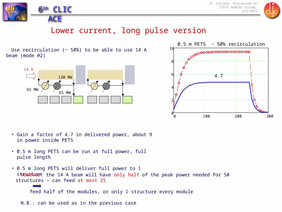
100.5 m PETS - 50% recirculation
4.7
Use recirculation (~ 50%) to be able to use 14 A beam (mode #2)
• Gain a factor of 4.7 in delivered power, about 9 in power inside PETS
• 0.5 m long PETS can be run at full power, full pulse length
• 0.5 m long PETS will deliver full power to 1 structure
14 A
65 MW
130 MW
65 MW
However: the 14 A beam will have only half of the peak power needed for 50 structures – can feed at most 25
feed half of the modules, or only 1 structure every module
N.B.: can be used as in the previous case
Lower current, long pulse version

R. Corsini, Discussion on CTF3+ module string 3/2/20116th CLIC ACE
Another option, 28 A + recirculation
28 A
130 MW 130 MW
65 MW
130 MW
Use recirculation (~ 50%) to feed every second structure (mode #1)
• Could feed a total of ~12 modules this way
• Full power in PETS
• Pulse length only 140 ns
R. Corsini, Discussion on CTF3+ module string 3/2/20116th CLIC ACE
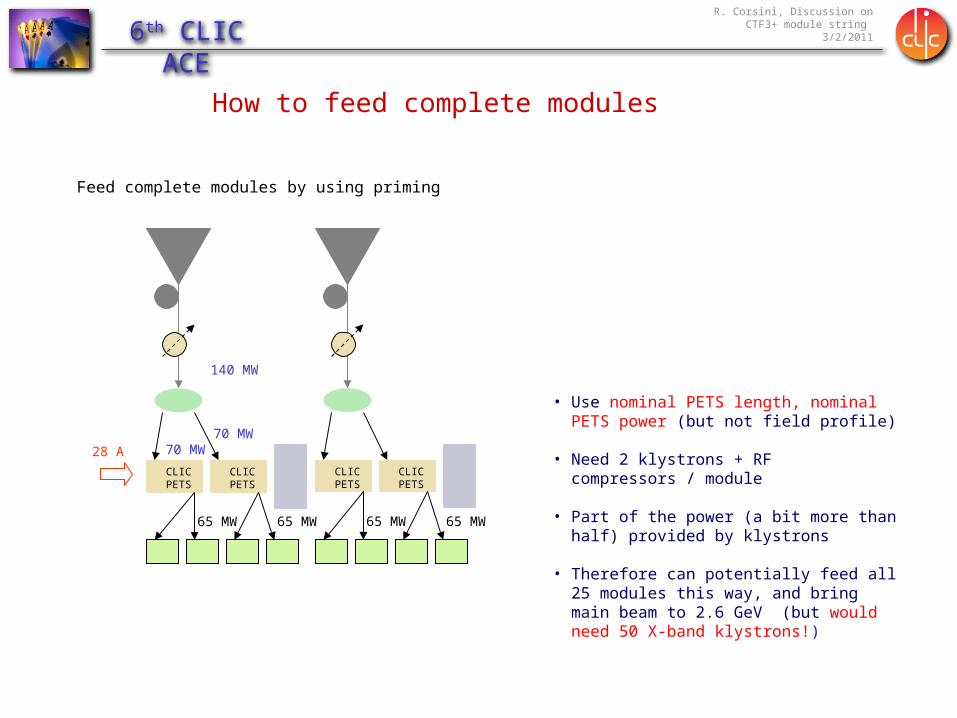
How to feed complete modules
Feed complete modules by using priming
65 MW 65 MW
140 MW
70 MW70 MW
CLIC PETS
CLIC PETS
65 MW 65 MW
CLIC PETS
CLIC PETS
• Use nominal PETS length, nominal PETS power (but not field profile)
• Need 2 klystrons + RF compressors / module
• Part of the power (a bit more than half) provided by klystrons
• Therefore can potentially feed all 25 modules this way, and bring main beam to 2.6 GeV (but would need 50 X-band klystrons!)
28 A
R. Corsini, Discussion on CTF3+ module string 3/2/20116th CLIC ACE
What can we learn with modules in CTF3?
• One
• A few
• Many

R. Corsini, Discussion on CTF3+ module string 3/2/20116th CLIC ACE
03 Feb 2011 16ACE, G. Riddone
Full system RF breakdown
RF waveguide network
Beam-based alignment
Cooling system performance
Vacuum system performance
Module engineering, and
assembly
Stabilization of main beam quadrupole
Vibration studyMeasurement of
resonant frequencies
Transport, installation and
maintenance
Metrology
What can we learn with modules in CTF3?

R. Corsini, Discussion on CTF3+ module string 3/2/20116th CLIC ACE
Two-Beam Module Type-I

R. Corsini, Discussion on CTF3+ module string 3/2/20116th CLIC ACE
Module RF Network• The two-beam RF network includes the X-band rectangular
wave-guides providing connection between PETS, AC and other supplementary devices.
• It’s necessary to join the PETS outgoing waves by one channel. Because of the limited longitudinal space a compact coupler is needed.
• In case of a breakdown in a AS it is necessary to interrupt the power produced by the corresponding PETS within 20 ms. “On-Off” mechanism
• Another requirement is to guarantee transverse alignment flexibility between the two beams and thus to allow for the power transmission without electrical contact
• Another necessity is to have a split of power between two AS without any reflection to the feeding PETS in a broad frequency range
• The power delivered from PETS to the two fed AS must be synchronized in phase
Components, integration of components

R. Corsini, Discussion on CTF3+ module string 3/2/20116th CLIC ACE
Main Beam RF Diagnostics
Two types of PETS+2AS units will be installed:
1. Reference (black) (2 units at the beginning and 2 units at the end of a DB sector)
• It will have more signals and with higher resolution • The signals will be time resolved: dt ~ 0.5 ns (pulse
shape)
2. Regular (blue) (all the rest)• It will have 1 or 2 signals• Integral over the pulse (1 or 2 numbers per pulse)
Courtesy of A. Grudiev
1. RF breakdown2. PETS on/off failure
• RF diagnostic1. RF breakdown in PETS and AS2. PETS on/off failure3. Provide references for the regular PETS+2AS units
• Beam control1. RF power production2. Energy measurement and beam loading transient
compensation
Use of diagnostics in operation

R. Corsini, Discussion on CTF3+ module string 3/2/20116th CLIC ACE
WakeField Monitors
Position monitors called Wakefield Monitors (WFM) are integrated to the structure for beam-based alignment (cost saving solution). There will be 1 WFM for each super-structure.
To achieve the target luminosity, the accelerating structures must be aligned to an accuracy of 3.5 μm with respect to the beam trajectory.
TBTS WakeField Monitor Prototype
From single structure to string…?

R. Corsini, Discussion on CTF3+ module string 3/2/20116th CLIC ACE
Some additional points:
• How many module “generations” will we have?
• It looks like we would need to test with beam at least a short string (~3) whenever they will undergo major changes. Keep existing modules in place or substitute them?
• What is the right balance between “LAB” modules and “CLEX” modules in the future?
• CLIC will probably be “rebaselined” on the 2012-2013 time scale. Is it worth to insist too much on nominal parameters when they could well change? (Remember CTF3 pulse length…)

R. Corsini, Discussion on CTF3+ module string 3/2/20116th CLIC ACE
Reserve

R. Corsini, Discussion on CTF3+ module string 3/2/20116th CLIC ACE
Beyond CTF3
• In the TDR phase, it is planned to build one full-scale drive beam injector (up to ~ 30 MeV).
• Thermionic + bunching system solution preferred w.r.t. photoinjector (possibly build both).
• Time scale around 2013.
• Need as well at least a few drive beam accelerator modules (klystron/modulator/structure)
• Present plan – add modules to arrive gradually at about 200 MeV (first bunch compression stage/ 10% of average CLIC beam power))
• Total cost: ~ 100 MCHF (including manpower)
• (Very) recent alternative: CLIC 0- (reduced cost CLIC0)

R. Corsini, Discussion on CTF3+ module string 3/2/20116th CLIC ACE
D. Schulte
Could cost (very preliminary) about 180 MCHF including rings, decelerator and probe beam injector
Halfway between Inj + 200MeV DBA and full CLIC0 (300 MCHF)
Another factor 2 in klystrons/modulators(reduced performance)

R. Corsini, Discussion on CTF3+ module string 3/2/20116th CLIC ACE
100 m
TBA
DBA0.48 GeV, 4.2 A
DL
CR2
CR1
Compression2 x 3 x 4
DB Turn around0.48 GeV, 101 A
6.5 GeV, 1.2 A
0.2 GeV, 101 A
CALIFES type injector0.2 GeV, 1.2 A
All other parameters nominal - all components nominal and re-usable for CLIC
CLIC Zero
20% of CLIC DB energy
10% of a CLIC decelerator sector
Option (cost): total pulse length in injector only

R. Corsini, Discussion on CTF3+ module string 3/2/20116th CLIC ACE
CLIC Zero – Pros & cons• Demonstrates nominal DBA injector with all parameters
• Creates nominal drive beam train apart from energy (0.48 GeV instead of 2.4 GeV)
• Demonstrates nominal DBA module with klystron and modulator with all parameters
• Demonstrates two beam acceleration over significant distance with fully nominal modules
• Forces pre-series production of all mass produced components → Industrialization
• Well suited to create confidence in CLIC technology
• All hardware investment is re-usable for real CLIC
• Expensive – will absorb most of planned budget
• Schedule too long – results with beam not before 2015
• No obvious use of 6.5 GeV main beam but for testing
• Drive beam dynamics more
difficult than in real CLIC (like in CTF3)