Embed Size (px)
Citation preview
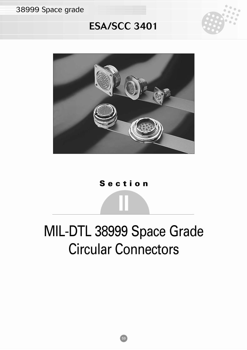
ESA/SCC 3401
38999 Space grade
59
S e c t i o n
MIL-DTL 38999 Space GradeCircular Connectors
II
ESA/SCC 3401
38999 Space Grade
60
Contents
• 38999 Space Grade ESA/SCC 3401
SCC Specification . . . . . . . . . . . . . . . . . . . . . . . . . . . . . . . . . . . . . . . . . . . . . . . . . . . . . . .61 Quality Assurance Testing . . . . . . . . . . . . . . . . . . . . . . . . . . . . . . . . . . . . . . . . . . . . . . . .61 CHART V - Lot Acceptance Tests . . . . . . . . . . . . . . . . . . . . . . . . . . . . . . . . . . . . . . . . . . 62Materials & Finishes . . . . . . . . . . . . . . . . . . . . . . . . . . . . . . . . . . . . . . . . . . . . . . . . . . . . .63 Electrical characteristics . . . . . . . . . . . . . . . . . . . . . . . . . . . . . . . . . . . . . . . . . . . . . . . . . .63 Environmental characteristics . . . . . . . . . . . . . . . . . . . . . . . . . . . . . . . . . . . . . . . . . . . . . .63
• 38999 Series I ESA/SCC 3401-052
Part Number / Ordering information . . . . . . . . . . . . . . . . . . . . . . . . . . . . . . . . . . . . . . . . 64TYPE 00 : Square flange receptacle front mounting . . . . . . . . . . . . . . . . . . . . . . . . . . . . .65 TYPE 03 : Square flange receptacle back mounting . . . . . . . . . . . . . . . . . . . . . . . . . . . . .65 TYPE 06G : Plug with grounding ring . . . . . . . . . . . . . . . . . . . . . . . . . . . . . . . . . . . . . . . .66 TYPE 07 : Single hole mounting receptacle . . . . . . . . . . . . . . . . . . . . . . . . . . . . . . . . . . . 66
• 38999 Series II ESA/SCC 3401-044
Part Number / Ordering information . . . . . . . . . . . . . . . . . . . . . . . . . . . . . . . . . . . . . . . . .67 TYPE 03 : Square flange receptacle (back mounting) . . . . . . . . . . . . . . . . . . . . . . . . . . . .68 TYPE 06 and 06G : Plug . . . . . . . . . . . . . . . . . . . . . . . . . . . . . . . . . . . . . . . . . . . . . . . . . .68 TYPE 07 : Single hole mounting receptacle . . . . . . . . . . . . . . . . . . . . . . . . . . . . . . . . . . .68
• 38999 Series III ESA/SCC 3401-056
Part Number / Ordering Information . . . . . . . . . . . . . . . . . . . . . . . . . . . . . . . . . . . . . . . . .69 TYPE 00 : Square flange receptacle . . . . . . . . . . . . . . . . . . . . . . . . . . . . . . . . . . . . . . . . .70 TYPE 06G : Plug with grounding ring . . . . . . . . . . . . . . . . . . . . . . . . . . . . . . . . . . . . . . . .70 TYPE 66G : Plug with mirror image contact . . . . . . . . . . . . . . . . . . . . . . . . . . . . . . . . . . .70 TYPE 07 : Single hole mounting receptacle . . . . . . . . . . . . . . . . . . . . . . . . . . . . . . . . . . .71
• 38999 Series III ESA/SCC 3401-070
Type 00 : Square flange receptacle straight spill . . . . . . . . . . . . . . . . . . . . . . . . . . . . . . . .77 Type 07 : Single hole mounting receptacle straight spill . . . . . . . . . . . . . . . . . . . . . . . . . .78
• 38999 Series III - Hermetic receptacle ESA/SCC 3401-051
Part Number / Ordering Information . . . . . . . . . . . . . . . . . . . . . . . . . . . . . . . . . . . . . . . . .80 TYPE 00 : Square flange receptacle . . . . . . . . . . . . . . . . . . . . . . . . . . . . . . . . . . . . . . . . .81 TYPE 01 : Solder mount receptacle . . . . . . . . . . . . . . . . . . . . . . . . . . . . . . . . . . . . . . . . .81 TYPE 07 : Single hole mounting receptacle . . . . . . . . . . . . . . . . . . . . . . . . . . . . . . . . . . .82 TYPE 77 H : Feedthrough receptacle . . . . . . . . . . . . . . . . . . . . . . . . . . . . . . . . . . . . . . . .82
• 38999 Series I, II, III & III Hermetic
Contact layouts for ESA/SCC 3401 052, 3401 044, 3401 056 & 3401 057 . . . . . . . . . . . . 83
• 38999 Series : Crimp Contacts
Crimp contacts . . . . . . . . . . . . . . . . . . . . . . . . . . . . . . . . . . . . . . . . . . . . . . . . . . . . . . . . .84 Tooling for crimp contacts . . . . . . . . . . . . . . . . . . . . . . . . . . . . . . . . . . . . . . . . . . . . . . . .84
• 38999 Series : Accessories
Part Number / Ordering Information . . . . . . . . . . . . . . . . . . . . . . . . . . . . . . . . . . . . . . . . 85Table of variant types . . . . . . . . . . . . . . . . . . . . . . . . . . . . . . . . . . . . . . . . . . . . . . . . . . . .85 Dimensions . . . . . . . . . . . . . . . . . . . . . . . . . . . . . . . . . . . . . . . . . . . . . . . . . . . . . . . . . . .86
61
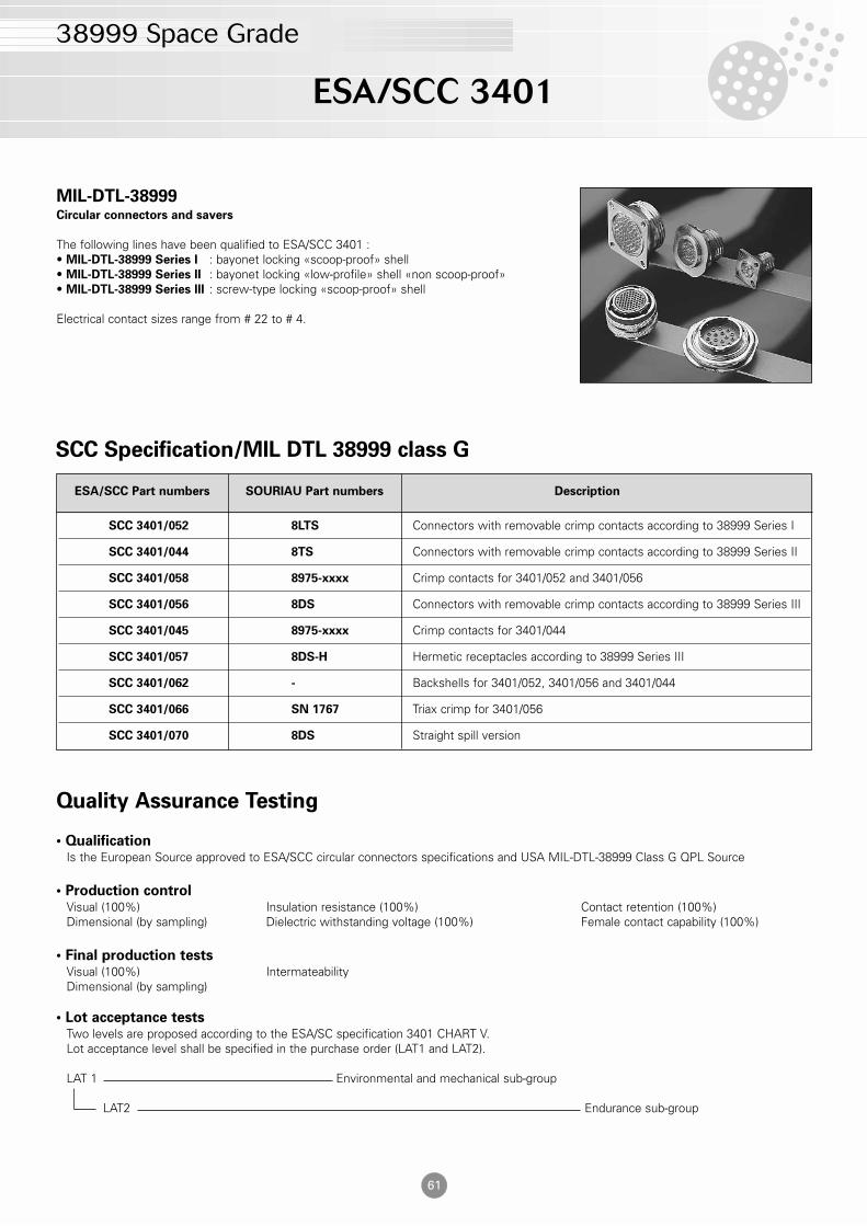
MIL-DTL-38999Circular connectors and savers
The following lines have been qualified to ESA/SCC 3401 :• MIL-DTL-38999 Series I : bayonet locking «scoop-proof» shell• MIL-DTL-38999 Series II : bayonet locking «low-profile» shell «non scoop-proof»• MIL-DTL-38999 Series III : screw-type locking «scoop-proof» shell
Electrical contact sizes range from # 22 to # 4.
SCC Specification/MIL DTL 38999 class G
ESA/SCC Part numbers SOURIAU Part numbers Description
SCC 3401/052 8LTS Connectors with removable crimp contacts according to 38999 Series I
SCC 3401/044 8TS Connectors with removable crimp contacts according to 38999 Series II
SCC 3401/058 8975-xxxx Crimp contacts for 3401/052 and 3401/056
SCC 3401/056 8DS Connectors with removable crimp contacts according to 38999 Series III
SCC 3401/045 8975-xxxx Crimp contacts for 3401/044
SCC 3401/057 8DS-H Hermetic receptacles according to 38999 Series III
SCC 3401/062 - Backshells for 3401/052, 3401/056 and 3401/044
SCC 3401/066 SN 1767 Triax crimp for 3401/056
SCC 3401/070 8DS Straight spill version
Quality Assurance Testing
• QualificationIs the European Source approved to ESA/SCC circular connectors specifications and USA MIL-DTL-38999 Class G QPL Source
• Production controlVisual (100%) Insulation resistance (100%) Contact retention (100%)Dimensional (by sampling) Dielectric withstanding voltage (100%) Female contact capability (100%)
• Final production testsVisual (100%) IntermateabilityDimensional (by sampling)
• Lot acceptance testsTwo levels are proposed according to the ESA/SC specification 3401 CHART V.Lot acceptance level shall be specified in the purchase order (LAT1 and LAT2).
LAT 1 Environmental and mechanical sub-group
LAT2 Endurance sub-group
ESA/SCC 3401
38999 Space Grade
62
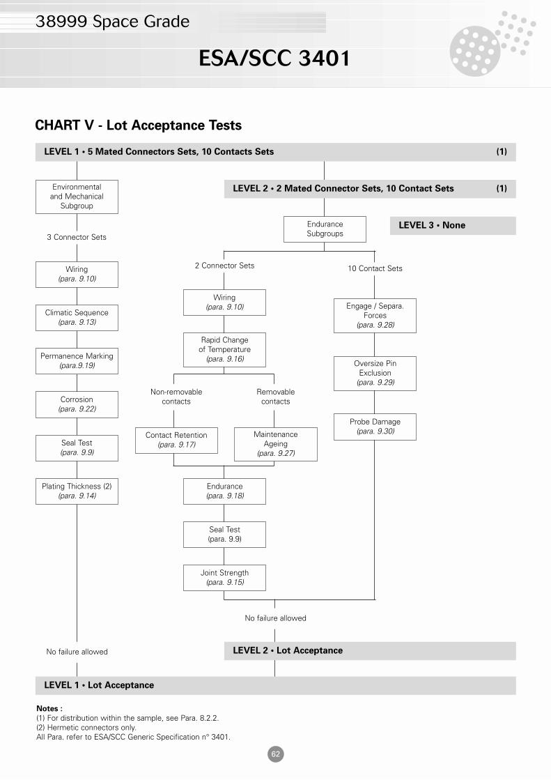
CHART V - Lot Acceptance Tests
Notes :
(1) For distribution within the sample, see Para. 8.2.2. (2) Hermetic connectors only.All Para. refer to ESA/SCC Generic Specification n° 3401.
LEVEL 3 • None
LEVEL 2 • 2 Mated Connector Sets, 10 Contact Sets (1)
EnduranceSubgroups
2 Connector Sets
Wiring(para. 9.10)
Rapid Changeof Temperature
(para. 9.16)
Non-removablecontacts
Contact Retention(para. 9.17)
Removablecontacts
MaintenanceAgeing
(para. 9.27)
Endurance(para. 9.18)
Seal Test(para. 9.9)
Joint Strength(para. 9.15)
LEVEL 2 • Lot Acceptance
No failure allowed
10 Contact Sets
Engage / Separa.Forces
(para. 9.28)
Oversize PinExclusion
(para. 9.29)
Probe Damage(para. 9.30)
LEVEL 1 • 5 Mated Connectors Sets, 10 Contacts Sets (1)
LEVEL 1 • Lot Acceptance
No failure allowed
Plating Thickness (2)(para. 9.14)
Seal Test(para. 9.9)
Corrosion(para. 9.22)
Permanence Marking(para.9.19)
Climatic Sequence(para. 9.13)
Wiring(para. 9.10)
3 Connector Sets
Environmentaland Mechanical
Subgroup
ESA/SCC 3401
38999 Space Grade
63
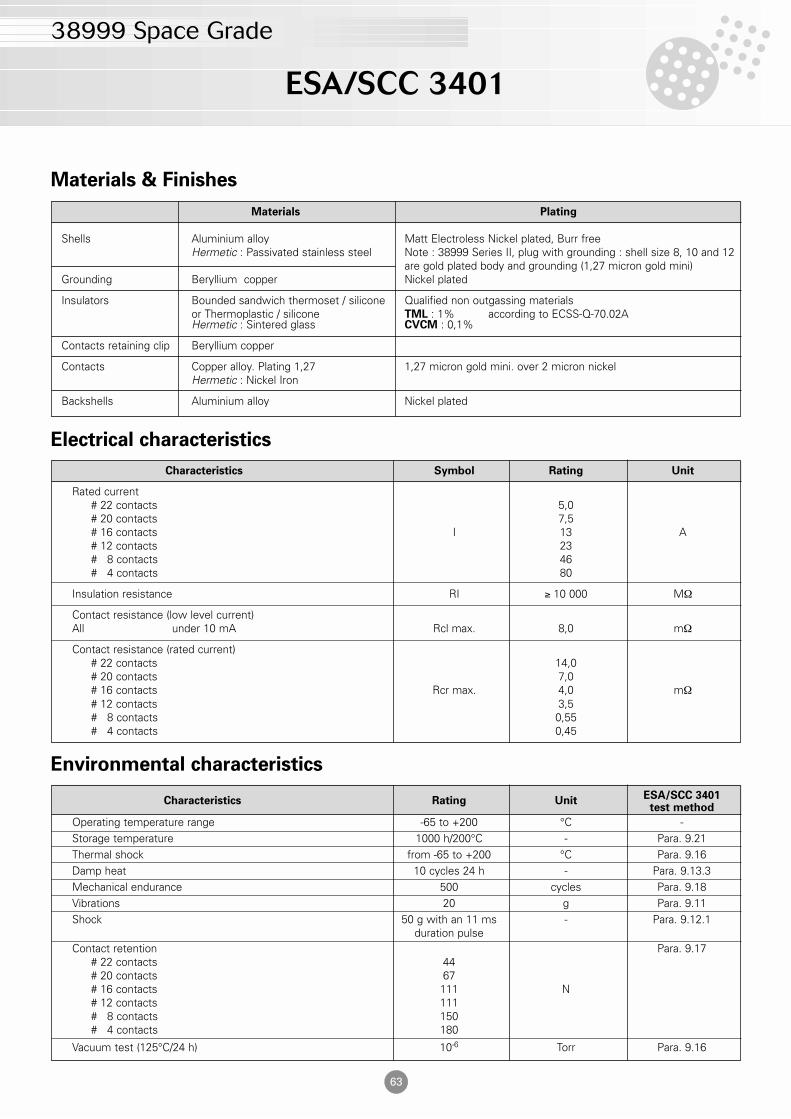
Materials & Finishes
Electrical characteristics
Environmental characteristics
Materials Plating
Shells Aluminium alloy Matt Electroless Nickel plated, Burr freeHermetic : Passivated stainless steel Note : 38999 Series II, plug with grounding : shell size 8, 10 and 12
are gold plated body and grounding (1,27 micron gold mini)Grounding Beryllium copper Nickel plated
Insulators Bounded sandwich thermoset / silicone Qualified non outgassing materialsor Thermoplastic / silicone TML : 1% according to ECSS-Q-70.02AHermetic : Sintered glass CVCM : 0,1%
Contacts retaining clip Beryllium copper
Contacts Copper alloy. Plating 1,27 1,27 micron gold mini. over 2 micron nickelHermetic : Nickel Iron
Backshells Aluminium alloy Nickel plated
Characteristics Symbol Rating Unit
Rated current# 22 contacts 5,0# 20 contacts 7,5# 16 contacts I 13 A# 12 contacts 23# 8 contacts 46# 4 contacts 80
Insulation resistance RI ≥ 10 000 MΩ
Contact resistance (low level current)All under 10 mA Rcl max. 8,0 mΩ
Contact resistance (rated current)# 22 contacts 14,0# 20 contacts 7,0# 16 contacts Rcr max. 4,0 mΩ# 12 contacts 3,5# 8 contacts 0,55# 4 contacts 0,45
Characteristics Rating UnitESA/SCC 3401test method
Operating temperature range -65 to +200 °C -Storage temperature 1000 h/200°C - Para. 9.21Thermal shock from -65 to +200 °C Para. 9.16Damp heat 10 cycles 24 h - Para. 9.13.3Mechanical endurance 500 cycles Para. 9.18Vibrations 20 g Para. 9.11Shock 50 g with an 11 ms - Para. 9.12.1
duration pulseContact retention Para. 9.17
# 22 contacts 44# 20 contacts 67# 16 contacts 111 N# 12 contacts 111# 8 contacts 150# 4 contacts 180
Vacuum test (125°C/24 h) 10-6 Torr Para. 9.16
ESA/SCC 3401
38999 Space Grade
64
L : connectors ordered without contacts («L» is not marked on the connector)connectors are only supplied less contacts
Clocking position
N : normal (standard clocking position)Other positions : A, B, C & D
Circular connectors with
removable crimp contacts
ESA/SCC 3401/052 are used with 3401/058crimp contacts. This series is suitable forFlight Models.
8LTS Series uses the same componentsas 3401/052 it is derived from. They aredelivered without traceability and LATtesting which often complies withEngineering Models requirements.
Applications
SatelliteLauncherSpace stationShuttle hardware
Standards
ESA/SCC 3401/052/MIL-DTL-38999 class G (QPL)
Contact type
P : pin S : socket
Contact arrangement
(see table page 83)
Shell size
09 - 11 - 13 - 15 - 17 - 19 - 21 - 23 -25
Shell type
00 : square flange receptacle (front mounting)03 : square flange receptacle (rear mounting)06 : plug (with grouding ring)07 : single hole mounting receptacle
B testing level
not to be modified
Type of variant ESA
not to be modified
Part Number / Ordering information
3401 052 01 B 00 13 35 P N LSCC specification number
L : connectors ordered without contacts («L» is not marked on the connector)connectors are only supplied less contacts
Clocking position
N : normalOther positions : A, B, C & D
Contact type
P : pin S : socket
Contact arrangement
(see table page 83)
Shell size
09 - 11 - 13 - 15 - 17 - 19 - 21 - 23 -25
Shell type
00 : square flange receptacle (front mounting)03 : square flange receptacle (rear mounting)06G : plug («G» for grounding)07 : single hole mounting receptacle
8LTS 00 13 35 P N L8LTS Series
38999 Series I
38999 Series I
65
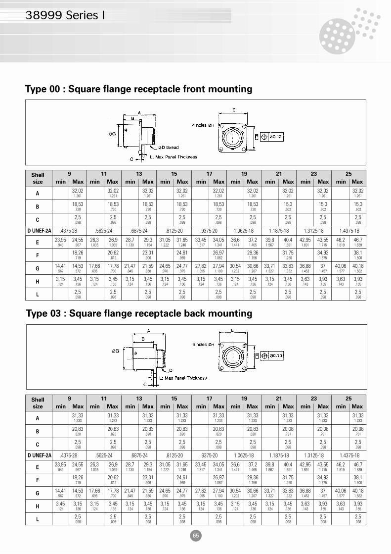
Type 00 : Square flange receptacle front mounting
Shell
size min Max min Max min Max min Max min Max min Max min Max min Max min Max
Type 03 : Square flange receptacle back mounting
9 11 13 15 17 19 21 23 25
A32,02 32,02 32,02 32,02 32,02 32,02 32,02 32,02 32,021.261 1.261 1.261 1.261 1.261 1.261 1.261 1.261 1.261
B18,53 18,53 18,53 18,53 18,53 18,53 15,3 15,3 15,3
.730 .730 .730 .730 .730 .730 .602 .602 .602
C2,5 2,5 2,5 2,5 2,5 2,5 2,5 2,5 2,5.098 .098 .098 .098 .098 .098 .098 .098 .098
E23,95 24,55 26,3 26,9 28,7 29,3 31,05 31,65 33,45 34,05 36,6 37,2 39,8 40,4 42,95 43,55 46,2 46,7
.943 .967 1.035 1.059 1.130 1.154 1.222 1.246 1.317 1.341 1.441 1.465 1.567 1.591 1.691 1.715 1.819 1.839
G14,41 14,53 17,66 17,78 21,47 21,59 24,65 24,77 27,82 27,94 30,54 30,66 33,71 33,83 36,88 37 40,06 40,18
.567 .572 .695 .700 .845 .850 .970 .975 1.095 1.100 1.202 1.207 1.327 1.332 1.452 1.457 1.577 1.582
H3,15 3,45 3,15 3,45 3,15 3,45 3,15 3,45 3,15 3,45 3,15 3,45 3,15 3,45 3,63 3,93 3,63 3,93.124 .136 .124 .136 .124 .136 .124 .136 .124 .136 .124 .136 .124 .136 .143 .155 .143 .155
F18,26 20,62 23,01 24,61 26,97 29,36 31,75 34,93 38,1
.719 .812 .906 .969 1.062 1.156 1.250 1.375 1.500
L2,5 2,5 2,5 2,5 2,5 2,5 2,5 2,5 2,5.098 .098 .098 .098 .098 .098 .098 .098 .098
D UNEF-2A .4375-28 .5625-24 .6875-24 .8125-20 .9375-20 1.0625-18 1.1875-18 1.3125-18 1.4375-18
Shell
size min Max min Max min Max min Max min Max min Max min Max min Max min Max
9 11 13 15 17 19 21 23 25
A31,33 31,33 31,33 31,33 31,33 31,33 31,33 31,33 31,331.233 1.233 1.233 1.233 1.233 1.233 1.233 1.233 1.233
B20,83 20,83 20,83 20,83 20,83 20,83 20,08 20,08 20,08
.820 .820 .820 .820 .820 .820 .791 .791 .791
C2,5 2,5 2,5 2,5 2,5 2,5 2,5 2,5 2,5.098 .098 .098 .098 .098 .098 .098 .098 .098
E23,95 24,55 26,3 26,9 28,7 29,3 31,05 31,65 33,45 34,05 36,6 37,2 39,8 40,4 42,95 43,55 46,2 46,7
.943 .967 1.035 1.059 1.130 1.154 1.222 1.246 1.317 1.341 1.441 1.465 1.567 1.591 1.691 1.715 1.819 1.839
G14,41 14,53 17,66 17,78 21,47 21,59 24,65 24,77 27,82 27,94 30,54 30,66 33,71 33,83 36,88 37 40,06 40,18
.567 .572 .695 .700 .845 .850 .970 .975 1.095 1.100 1.202 1.207 1.327 1.332 1.452 1.457 1.577 1.582
H3,45 3,15 3,15 3,45 3,15 3,45 3,15 3,45 3,15 3,45 3,15 3,45 3,15 3,45 3,63 3,93 3,63 3,93.124 .136 .124 .136 .124 .136 .124 .136 .124 .136 .124 .136 .124 .136 .143 .155 .143 .155
F18,26 20,62 23,01 24,61 26,97 29,36 31,75 34,93 38,1
.719 .812 .906 .969 1.062 1.156 1.250 1.375 1.500
L2,5 2,5 2,5 2,5 2,5 2,5 2,5 2,5 2,5.098 .098 .098 .098 .098 .098 .098 .098 .098
D UNEF-2A .4375-28 .5625-24 .6875-24 .8125-20 .9375-20 1.0625-18 1.1875-18 1.3125-18 1.4375-18
38999 Series I
66
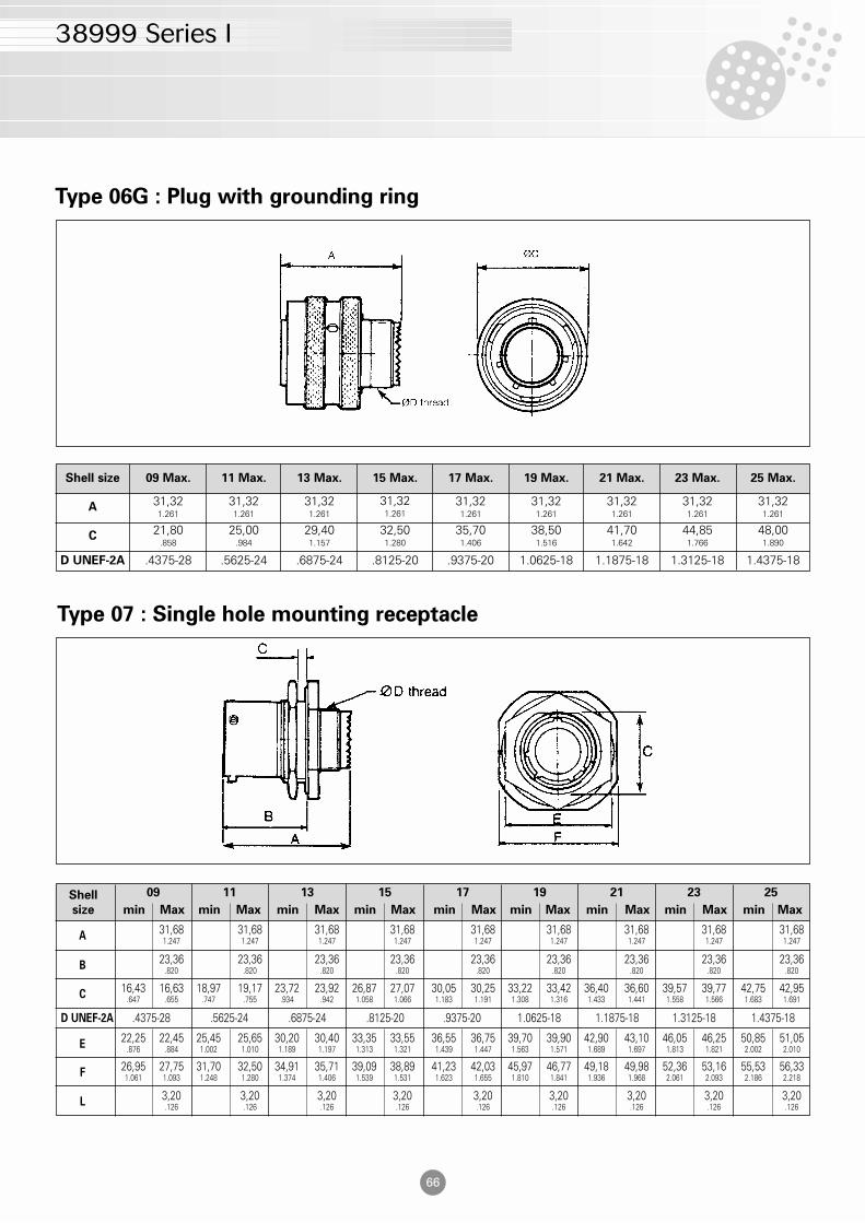
Type 06G : Plug with grounding ring
Type 07 : Single hole mounting receptacle
Shell
size min Max min Max min Max min Max min Max min Max min Max min Max min Max
09 11 13 15 17 19 21 23 25
A31,68 31,68 31,68 31,68 31,68 31,68 31,68 31,68 31,681.247 1.247 1.247 1.247 1.247 1.247 1.247 1.247 1.247
B23,36 23,36 23,36 23,36 23,36 23,36 23,36 23,36 23,36
.820 .820 .820 .820 .820 .820 .820 .820 .820
C16,43 16,63 18,97 19,17 23,72 23,92 26,87 27,07 30,05 30,25 33,22 33,42 36,40 36,60 39,57 39,77 42,75 42,95
.647 .655 .747 .755 .934 .942 1.058 1.066 1.183 1.191 1.308 1.316 1.433 1.441 1.558 1.566 1.683 1.691
E22,25 22,45 25,45 25,65 30,20 30,40 33,35 33,55 36,55 36,75 39,70 39,90 42,90 43,10 46,05 46,25 50,85 51,05
.876 .884 1.002 1.010 1.189 1.197 1.313 1.321 1.439 1.447 1.563 1.571 1.689 1.697 1.813 1.821 2.002 2.010
L3,20 3,20 3,20 3,20 3,20 3,20 3,20 3,20 3,20.126 .126 .126 .126 .126 .126 .126 .126 .126
F26,95 27,75 31,70 32,50 34,91 35,71 39,09 38,89 41,23 42,03 45,97 46,77 49,18 49,98 52,36 53,16 55,53 56,331.061 1.093 1.248 1.280 1.374 1.406 1.539 1.531 1.623 1.655 1.810 1.841 1.936 1.968 2.061 2.093 2.186 2.218
D UNEF-2A .4375-28 .5625-24 .6875-24 .8125-20 .9375-20 1.0625-18 1.1875-18 1.3125-18 1.4375-18
Shell size 09 Max. 11 Max. 13 Max. 15 Max. 17 Max. 19 Max. 21 Max. 23 Max. 25 Max.
A 31,321.261
31,321.261
31,321.261
31,321.261
31,321.261
31,321.261
31,321.261
31,321.261
31,321.261
C 21,80.858
25,00.984
29,401.157
32,501.280
35,701.406
38,501.516
41,701.642
44,851.766
48,001.890
D UNEF-2A .4375-28 .5625-24 .6875-24 .8125-20 .9375-20 1.0625-18 1.1875-18 1.3125-18 1.4375-18
38999 Series II
67
L : connectors ordered without contacts («L» is not marked on the connector)connectors are only supplied less contacts
Clocking position
N : normal (standard clocking position)Other positions : A, B, C & D
Circular connectors with
removable crimp contacts
ESA/SCC 3401/044 are used with 3401/045crimp contacts. This series is suitable forFlight Models.
8TS Series uses the same componentsas 3401/044 it is derived from. They aredelivered without traceability and LATtesting which often complies withEngineering Models requirements.
Applications
SatelliteLauncherSpace stationShuttle hardware
Standards
ESA/SCC 3401/044/MIL-DTL-38999class G (QPL)
Contact type
P : pin S : socket
Contact arrangement
(see table page 83)
Shell size
08 - 10 - 12 - 14 - 16 - 18 - 20 - 22 - 24
Shell type
03 : square flange receptacle (rear mounting)06 : plug (without grounding)06G : plug («G» for grounding)07 : single hole mounting receptacle
B testing level
not to be modified
Type of variant ESA
not to be modified
Part Number / Ordering information
3401 044 01 B 00 12 35 P N LSCC specification number
L : connectors ordered without contacts («L» is not marked on the connector)connectors are only supplied less contacts
Clocking position
N : normal (standard clocking position)Other positions : A, B, C & D
Contact type
P : pin S : socket
Contact arrangement
(see table page 83)
Shell size
08 - 10 - 12 - 14 - 16 - 18 - 20 - 22 - 24
Shell type
03 : square flange receptacle (rear mounting)06 : plug (without grounding)06G : plug («G» for grounding)07 : single hole mounting receptacle
8TS 00 12 35 P N L8TS Series
38999 Series II
68
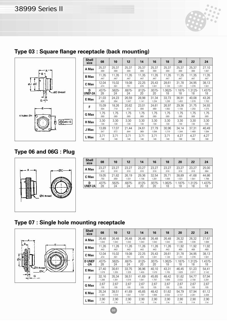
Type 03 : Square flange receptacle (back mounting)
Type 06 and 06G : Plug
Type 07 : Single hole mounting receptacle
Shell08 10 12 14 16 18 20 22 24size
Shell08 10 12 14 16 18 20 22 24size
A Max25,37 25,37 25,37 25,37 25,37 25,37 25,37 25,37 27,10
.999 .999 .999 .999 .999 .999 .999 .999 1.067
B Max11,35 11,35 11,35 11,35 11,35 11,35 11,35 11,35 11,35
.447 .447 .447 .447 .447 .447 .447 .447 .447
C Max12,04 15,02 19,08 22,25 25,43 28,61 31,78 34,95 38,13
.474 .591 .751 .876 1.001 1.126 1.251 1.376 1.501
D .4375- .5625- .6875- .8125- .9375- 1.0625- 1.1875- 1.3125- 1.4375-UNEF-2A 28 24 24 20 20 18 18 18 18
E Max21,03 24,23 26,59 28,98 31,34 33,73 36,91 40,08 43,26
.828 .954 1.047 1.141 1.234 1.238 1.453 1.578 1.703
F15,09 18,26 20,62 23,01 24,61 26,97 29,36 31,75 34,93
.594 .719 .812 .906 .969 1.062 1.156 1.250 1.375
G Max1,75 1,75 1,75 1,75 1,75 1,75 1,75 1,75 1,75.069 .069 .069 .069 .069 .069 .069 .069 .069
H Max3,30 3,30 3,30 3,30 3,30 3,30 3,30 3,30 3,30.130 .130 .130 .130 .130 .130 .130 .130 .130
J Max13,89 17,07 21,44 24,61 27,79 30,96 34,14 37,31 40,49
.547 .672 .844 .969 1.094 1.219 1.344 1.469 1.594
L Max3,71 3,71 3,71 3,71 3,71 3,71 4,27 4,27 4,27.146 .146 .146 .146 .146 .146 .168 .168 .168
A Max23,27 23,27 23,27 23,27 23,27 23,27 23,27 23,27 25,00
.916 .916 .916 .916 .916 .916 .916 .916 .984
C Max19,05 21,82 26,19 29,36 32,54 35,71 38,89 41,68 44,86
.750 .859 1.031 1.156 1.281 1.406 1.531 1.641 1.766
D .4375- .5625- .6875- .8125- .9375- 1.0625- 1.1875- 1.3125- 1.4375-UNEF-2A 28 24 24 20 20 18 18 18 18
Shell08 10 12 14 16 18 20 22 24size
A Max26,48 26,48 26,48 26,48 26,48 26,48 26,32 26,32 27,671.043 1.043 1.043 1.043 1.043 1.043 1.036 1.036 1.089
B Max11,26 11,26 11,26 11,26 11,26 11,26 11,92 11,92 11,92
.443 .443 .443 .443 .443 .443 .469 .469 .469
C Max12,04 15,02 19,08 22,25 25,43 28,61 31,78 34,95 38,13
.474 .591 .751 .876 1.001 1.126 1.251 1.376 1.501
D UNEF .4375- .5625- .6875- .8125- .9375- 1.0625- 1.1875- 1.3125- 1.4375--2A 28 24 24 20 20 18 18 18 18
E Max27,40 30,61 33,75 36,96 40,10 43,31 46,45 51,23 54,411.079 1.205 1.329 1.455 1.579 1.705 1.829 2.017 2.142
F32,16 35,34 38,51 41,69 45,65 48,42 51,62 54,77 57,941.266 1.391 1.516 1.641 1.797 1.906 2.032 2.156 2.281
G Max2,67 2,67 2,67 2,67 2,67 2,67 2,67 2,67 2,67.105 .105 .105 .105 .105 .105 .105 .105 .105
K Max35,34 38,51 41,69 45,65 48,42 51,62 54,79 57,94 61,121.391 1.516 1.641 1.797 1.906 2.032 2.157 2.281 2.406
L Max2,90 2,90 2,90 2,90 2,90 2,90 2,90 2,90 2,90.114 .114 .114 .114 .114 .114 .114 .114 .114
38999 Series III
69
L : connectors ordered without contacts («L» is not marked on the connector)connectors are only supplied less contacts
Clocking position
N : normal (standard clocking position)Other positions : A, B, C, D & E
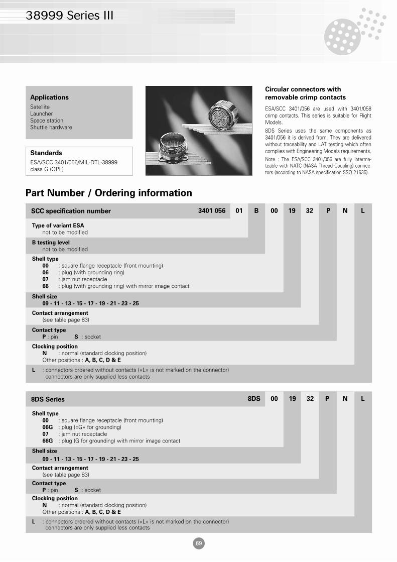
Circular connectors with
removable crimp contacts
ESA/SCC 3401/056 are used with 3401/058crimp contacts. This series is suitable for FlightModels.8DS Series uses the same components as3401/056 it is derived from. They are deliveredwithout traceability and LAT testing which oftencomplies with Engineering Models requirements.Note : The ESA/SCC 3401/056 are fully interma-teable with NATC (NASA Thread Coupling) connec-tors (according to NASA specification SSQ 21635).
Applications
SatelliteLauncherSpace stationShuttle hardware
Standards
ESA/SCC 3401/056/MIL-DTL-38999class G (QPL)
Contact type
P : pin S : socket
Contact arrangement
(see table page 83)
Shell size
09 - 11 - 13 - 15 - 17 - 19 - 21 - 23 - 25
Shell type
00 : square flange receptacle (front mounting)06 : plug (with grounding ring)07 : jam nut receptacle66 : plug (with grounding ring) with mirror image contact
B testing level
not to be modified
Type of variant ESA
not to be modified
Part Number / Ordering information
3401 056 01 B 00 19 32 P N LSCC specification number
L : connectors ordered without contacts («L» is not marked on the connector)connectors are only supplied less contacts
Clocking position
N : normal (standard clocking position)Other positions : A, B, C, D & E
Contact type
P : pin S : socket
Contact arrangement
(see table page 83)
Shell size
09 - 11 - 13 - 15 - 17 - 19 - 21 - 23 - 25
Shell type
00 : square flange receptacle (front mounting)06G : plug («G» for grounding)07 : jam nut receptacle66G : plug (G for grounding) with mirror image contact
8DS 00 19 32 P N L8DS Series
38999 Series III
70
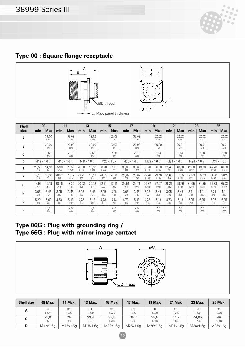
Type 00 : Square flange receptacle
Shell
size min Max min Max min Max min Max min Max min Max min Max min Max min Max
09 11 13 15 17 19 21 23 25
A31,50 32,02 32,02 32,02 32,02 32,02 32,02 32,02 32,021.240 1.261 1.261 1.261 1.261 1.261 1.261 1.261 1.261
B20,90 20,90 20,90 20,90 20,90 20,90 20,01 20,01 20,01
.823 .823 .823 .823 .823 .823 .791 .791 .791
C2,50 2,50 2,50 2,50 2,50 2,50 2,50 2,50 2,50.098 .098 .098 .098 .098 .098 .098 .098 .098
E23,50 24,10 25,90 26,50 28,30 28,90 30,70 31,30 33,00 33,60 36,20 36,80 39,40 40,00 42,60 43,20 45,70 46,30
.925 .949 1.020 1.043 1.114 1.138 1.209 1.232 1.299 1.323 1.425 1.449 1.551 1.575 1.677 1.701 1.799 1.823
G14,99 15,19 18,16 18,36 20,52 20,72 22,91 23,11 24,51 24,71 26,87 27,07 29,26 29,46 31,65 31,85 34,83 35,03
.567 .572 .715 .723 .808 .816 .902 .910 .965 .973 1.058 1.066 1.152 1.160 1.246 1.245 1.371 1.379
H3,05 3,45 3,05 3,45 3,05 3,45 3,05 3,45 3,05 3,45 3,05 3,45 3,05 3,45 3,71 4,11 3,71 4,11.120 .136 .120 .136 .120 .136 .120 .136 .120 .136 .120 .136 .120 .136 .146 .162 .146 .162
J5,29 5,69 4,73 5,13 4,73 5,13 4,73 5,13 4,73 5,13 4,73 5,13 4,73 5,13 5,95 6,35 5,95 6,35.208 .224 .186 .202 .186 .202 .186 .202 .186 .202 .186 .202 .186 .202 .234 .250 .234 .250
L2,5 2,5 2,5 2,5 2,5 2,5 2,5 2,5 2,5.098 .098 .098 .098 .098 .098 .098 .098 .098
F18,16 18,36 20,52 20,72 22,91 23,11 24,51 24,71 26,87 27,07 29,26 29,46 31,65 31,85 34,83 35,03 38,00 38,2
.715 .723 .808 .816 .902 .910 .965 .973 1.058 1.066 1.152 1.160 1.246 1.254 1.371 1.379 1.496 1.504
D M12 x 1-6 g M15 x 1-6 g M18x 1-6 g M22 x 1-6 g M25 x 1-6 g M28 x 1-6 g M31 x 1-6 g M34 x 1-6 g M37 x 1-6 g
Type 06G : Plug with grounding ring /
Type 66G : Plug with mirror image contact
Shell size 09 Max. 11 Max. 13 Max. 15 Max. 17 Max. 19 Max. 21 Max. 23 Max. 25 Max.
A 311.220
311.220
311.220
311.220
311.220
311.220
311.220
311.220
311.220
C 21,8.858
25.984
29,41.157
32,51.280
35,71.406
38,51.516
41,71.642
44,851.766
481.890
D M12x1-6g M15x1-6g M18x1-6g M22x1-6g M25x1-6g M28x1-6g M31x1-6g M34x1-6g M37x1-6g
38999 Series III
71
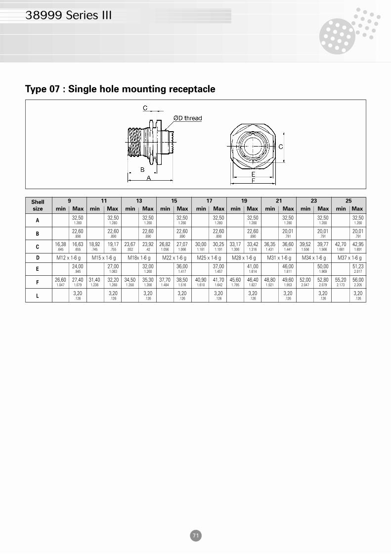
Type 07 : Single hole mounting receptacle
Shell
size min Max min Max min Max min Max min Max min Max min Max min Max min Max
9 11 13 15 17 19 21 23 25
A32,50 32,50 32,50 32,50 32,50 32,50 32,50 32,50 32,501.280 1.280 1.280 1.280 1.280 1.280 1.280 1.280 1.280
B22,60 22,60 22,60 22,60 22,60 22,60 20,01 20,01 20,01
.890 .890 .890 .890 .890 .890 .791 .791 .791
C16,38 16,63 18,92 19,17 23,67 23,92 26,82 27,07 30,00 30,25 33,17 33,42 36,35 36,60 39,52 39,77 42,70 42,95
.645 .655 .745 .755 .932 .42 1.056 1.066 1.181 1.191 1.306 1.316 1.431 1.441 1.556 1.566 1.681 1.691
F26,60 27,40 31,40 32,20 34,50 35,30 37,70 38,50 40,90 41,70 45,60 46,40 48,80 49,60 52,00 52,80 55,20 56,001.047 1.079 1.236 1.268 1.358 1.390 1.484 1.516 1.610 1.642 1.795 1.827 1.921 1.953 2.047 2.079 2.173 2.205
L3,20 3,20 3,20 3,20 3,20 3,20 3,20 3,20 3,20.126 .126 .126 .126 .126 .126 .126 .126 .126
E24,00 27,00 32,00 36,00 37,00 41,00 46,00 50,00 51,23
.945 1.063 1.260 1.417 1.457 1.614 1.811 1.969 2.017
D M12 x 1-6 g M15 x 1-6 g M18x 1-6 g M22 x 1-6 g M25 x 1-6 g M28 x 1-6 g M31 x 1-6 g M34 x 1-6 g M37 x 1-6 g
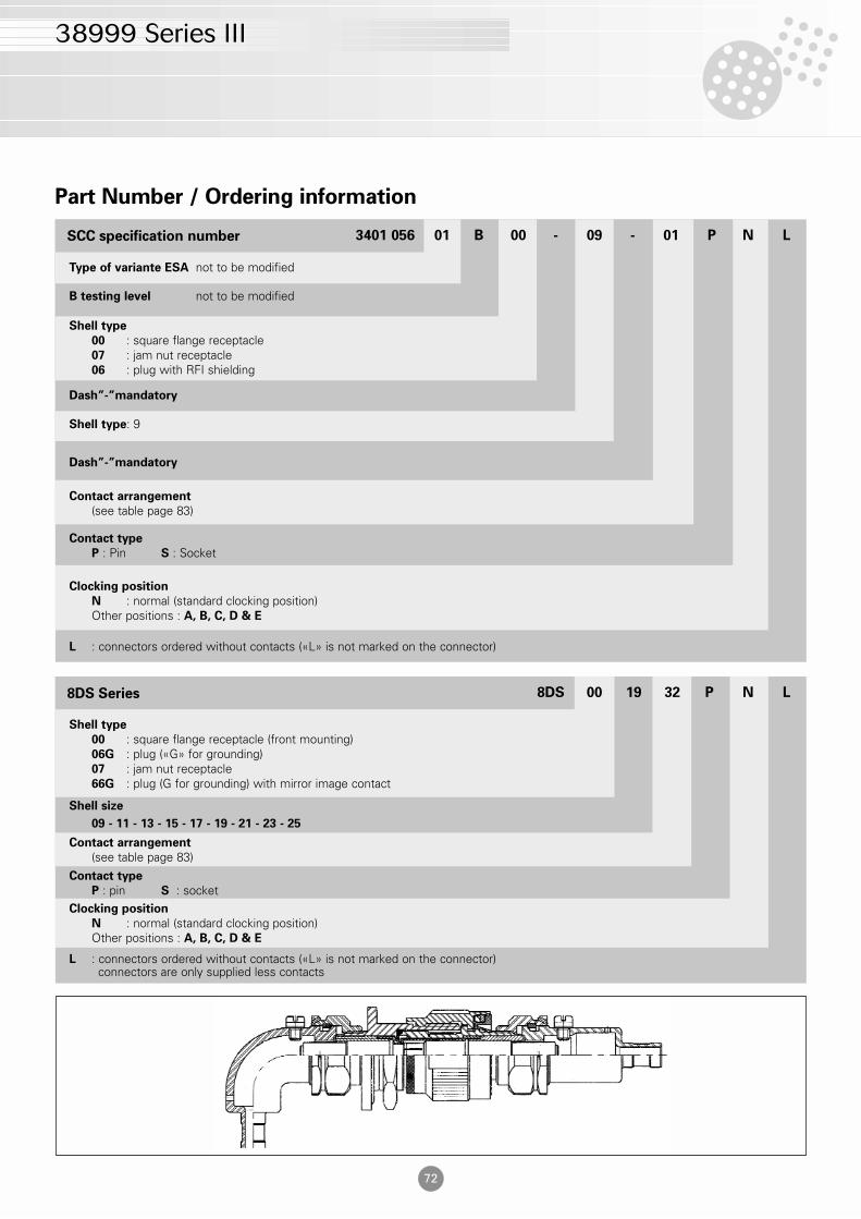
L : connectors ordered without contacts («L» is not marked on the connector)
38999 Series III
Clocking position
N : normal (standard clocking position)Other positions : A, B, C, D & E
72
Contact type
P : Pin S : Socket
Contact arrangement
(see table page 83)
Dash”-”mandatory
Dash”-”mandatory
Shell type: 9
Dash”-”mandatory
Shell type
00 : square flange receptacle 07 : jam nut receptacle06 : plug with RFI shielding
B testing level not to be modified
Type of variante ESA not to be modified
Part Number / Ordering information
3401 056 01 B 00 - 09 - 01 P N LSCC specification number
L : connectors ordered without contacts («L» is not marked on the connector)connectors are only supplied less contacts
Clocking position
N : normal (standard clocking position)Other positions : A, B, C, D & E
Contact type
P : pin S : socket
Contact arrangement
(see table page 83)
Shell size
09 - 11 - 13 - 15 - 17 - 19 - 21 - 23 - 25
Shell type
00 : square flange receptacle (front mounting)06G : plug («G» for grounding)07 : jam nut receptacle66G : plug (G for grounding) with mirror image contact
8DS 00 19 32 P N L8DS Series
38999 Series III
73
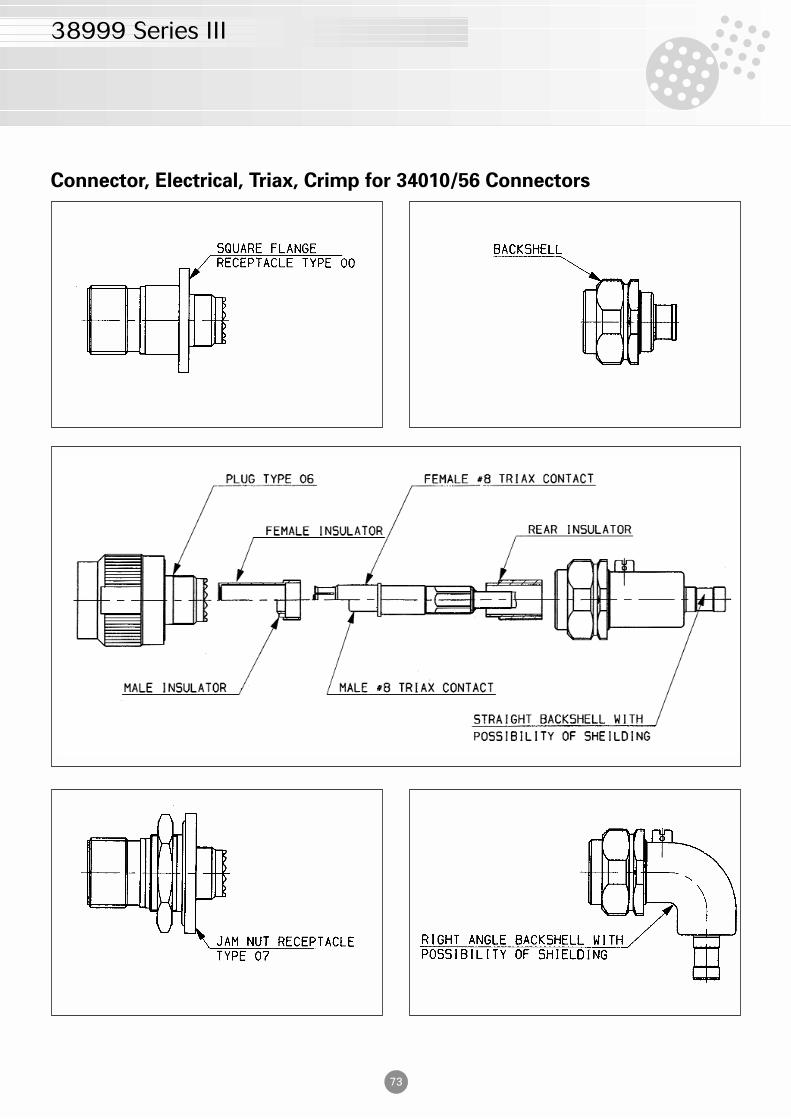
Connector, Electrical, Triax, Crimp for 34010/56 Connectors
74
38999 Series III
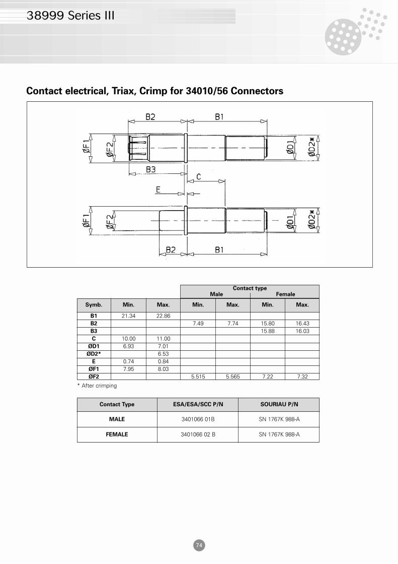
Contact electrical, Triax, Crimp for 34010/56 Connectors
Symb. Min. Max. Min. Max. Min. Max.
B1 21.34 22.86B2 7.49 7.74 15.80 16.43B3 15.88 16.03C 10.00 11.00
ØD1 6.93 7.01ØD2* 6.53
E 0.74 0.84ØF1 7.95 8.03ØF2 5.515 5.565 7.22 7.32
Contact typeMale Female
Contact Type ESA/ESA/SCC P/N SOURIAU P/N
MALE 3401066 01B SN 1767K 988-A
FEMALE 3401066 02 B SN 1767K 988-A
* After crimping
75
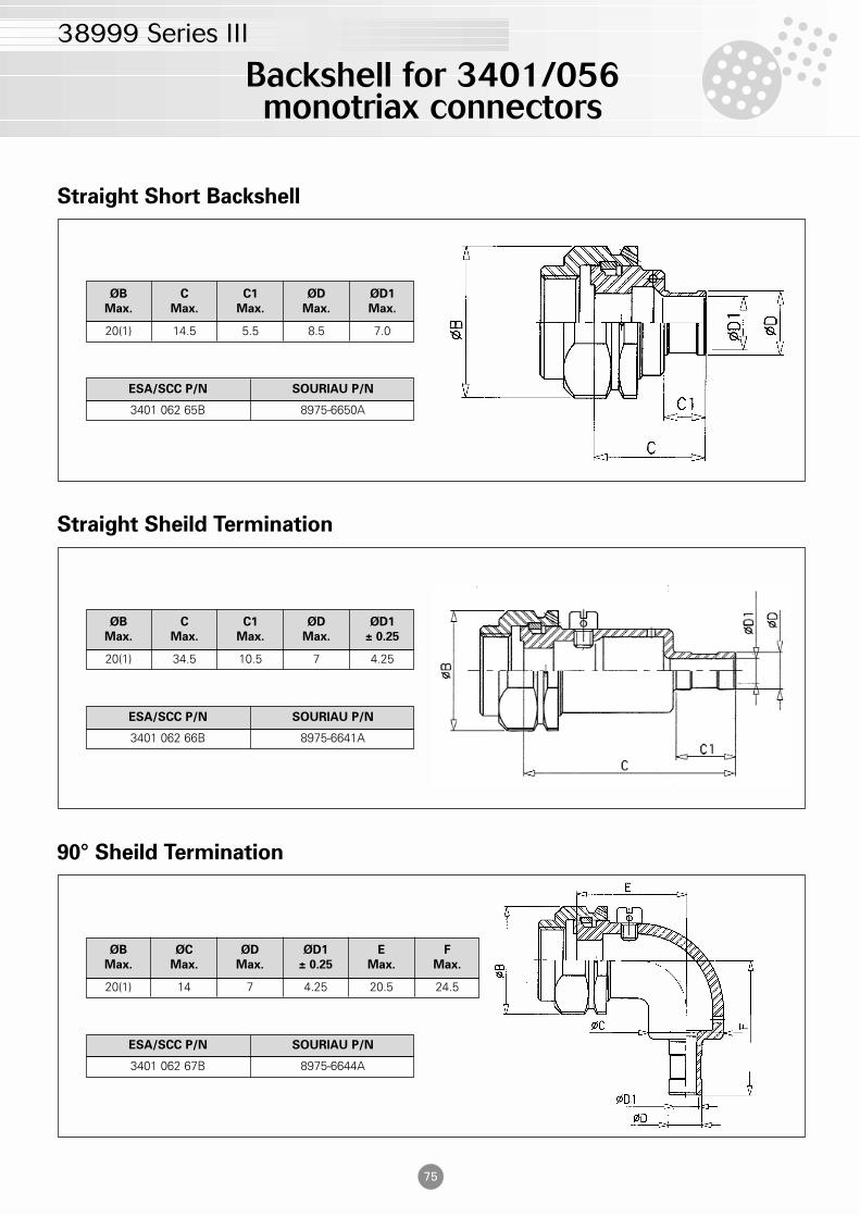
Backshell for 3401/056monotriax connectors
38999 Series III
Straight Short Backshell
ØB
Max.
C
Max.
C1
Max.
ØD
Max.
ØD1
Max.
20(1) 14.5 5.5 8.5 7.0
ESA/SCC P/N SOURIAU P/N
3401 062 65B 8975-6650A
Straight Sheild Termination
ØB
Max.
C
Max.
C1
Max.
ØD
Max.
ØD1
± 0.25
20(1) 34.5 10.5 7 4.25
ESA/SCC P/N SOURIAU P/N
3401 062 66B 8975-6641A
90° Sheild Termination
ØB
Max.
ØC
Max.
ØD
Max.
ØD1
± 0.25
E
Max.
F
Max.
20(1) 14 7 4.25 20.5 24.5
ESA/SCC P/N SOURIAU P/N
3401 062 67B 8975-6644A
Clocking position
N : NormalOther positions : A, B, C, D & E
Clocking position
N : normal (standard clocking position)Other positions : A, B, C, D & E
76
38999 Series III
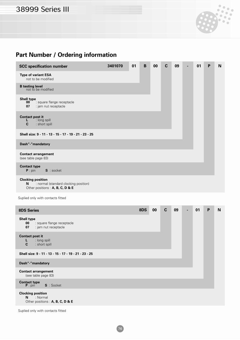
Contact type
P : pin S : socket
Contact type
P : pin S : socket
Contact arrangement
(see table page 83)
Dash”-”mandatory
Shell size: 9 - 11 - 13 - 15 - 17 - 19 - 21 - 23 - 25
Contact post itL : long spillC : short spill
Shell type00 : square flange receptacle07 : jam nut receptacle
B testing levelnot to be modified
Type of variant ESA
not to be modified
Part Number / Ordering information
3401070 01 B 00 C 09 - 01 P NSCC specification number
Contact typeP : pin S : Socket
Contact arrangement
(see table page 83)
Dash”-”mandatory
Shell size: 9 - 11 - 13 - 15 - 17 - 19 - 21 - 23 - 25
Contact post it
L : long spillC : short spill
Shell type
00 : square flange receptacle07 : jam nut receptacle
8DS 00 C 09 - 01 P N8DS Series
Suplied only with contacts fitted
Suplied only with contacts fitted
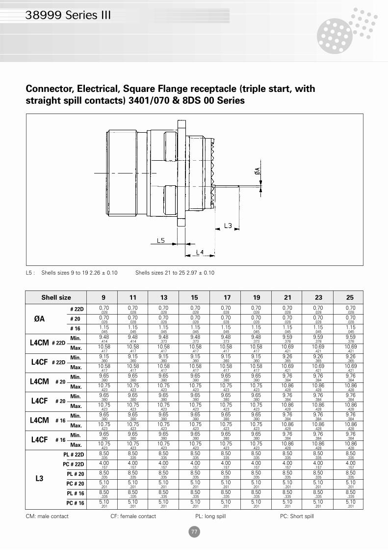
ØA
# 22D 0.70 0.70 0.70 0.70 0.70 0.70 0.70 0.70 0.70.028 .028 .028 .028 .028 .028 .028 .028 .028
# 20 0.70 0.70 0.70 0.70 0.70 0.70 0.70 0.70 0.70.028 .028 .028 .028 .028 .028 .028 .028 .028
# 16 1.15 1.15 1.15 1.15 1.15 1.15 1.15 1.15 1.15.045 .045 .045 .045 .045 .045 .045 .045 .045
L4CMMin. 9.48 9.48 9.48 9.48 9.48 9.48 9.59 9.59 9.59
.414 .414 .373 .373 .373 .373 .378 .378 .378
Max. 10.58 10.58 10.58 10.58 10.58 10.58 10.69 10.69 10.69.417 .417 .417 .417 .417 .417 .421 .421 .421
L4CFMin. 9.15 9.15 9.15 9.15 9.15 9.15 9.26 9.26 9.26
.360 .360 .360 .360 .360 .360 .365 .365 .365
Max. 10.58 10.58 10.58 10.58 10.58 10.58 10.69 10.69 10.69.417 .417 .417 .417 .417 .417 .421 .421 .421
L4CMMin. 9.65 9.65 9.65 9.65 9.65 9.65 9.76 9.76 9.76
.380 .380 .380 .380 .380 .380 .384 .384 .384
Max. 10.75 10.75 10.75 10.75 10.75 10.75 10.86 10.86 10.86.423 .423 .423 .423 .423 .423 .428 .428 .428
L4CFMin. 9.65 9.65 9.65 9.65 9.65 9.65 9.76 9.76 9.76
.380 .380 .380 .380 .380 .380 .384 .384 .384
Max. 10.75 10.75 10.75 10.75 10.75 10.75 10.86 10.86 10.86.423 .423 .423 .423 .423 .423 .428 .428 .428
PL # 22D 8.50 8.50 8.50 8.50 8.50 8.50 8.50 8.50 8.50.335 .335 .335 .335 .335 .335 .335 .335 .335
PC # 22D 4.00 4.00 4.00 4.00 4.00 4.00 4.00 4.00 4.00.157 .157 .157 .157 .157 .157 .157 .157 .157
L3PL # 20 8.50 8.50 8.50 8.50 8.50 8.50 8.50 8.50 8.50
.335 .335 .335 .335 .335 .335 .335 .335 .335
PC # 20 5.10 5.10 5.10 5.10 5.10 5.10 5.10 5.10 5.10.201 .201 .201 .201 .201 .201 ..201 .201 .201
PL # 16 8.50 8.50 8.50 8.50 8.50 8.50 8.50 8.50 8.50.335 .335 .335 .335 .335 .335 .335 .335 .335
PC # 16 5.10 5.10 5.10 5.10 5.10 5.10 5.10 5.10 5.10.201 .201 .201 .201 .201 .201 .201 .201 .201
Shell size 9 11 13 15 17 19 21 23 25
38999 Series III
Connector, Electrical, Square Flange receptacle (triple start, with
straight spill contacts) 3401/070 & 8DS 00 Series
L5 : Shells sizes 9 to 19 2.26 ± 0.10 Shells sizes 21 to 25 2.97 ± 0.10
# 22D
# 22D
# 20
# 20
# 16
# 16
CM: male contact CF: female contact PL: long spill PC: Short spill
77
78
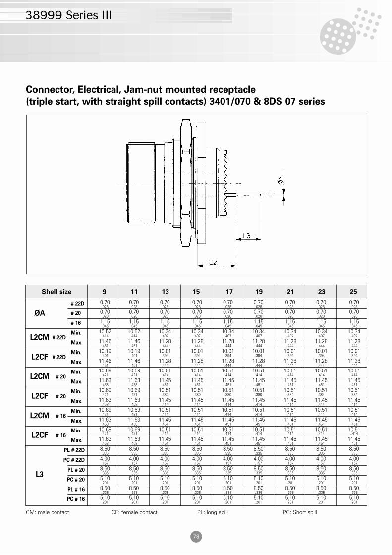
ØA
# 22D 0.70 0.70 0.70 0.70 0.70 0.70 0.70 0.70 0.70.028 .028 .028 .028 .028 .028 .028 .028 .028
# 20 0.70 0.70 0.70 0.70 0.70 0.70 0.70 0.70 0.70.028 .028 .028 .028 .028 .028 .028 .028 .028
# 16 1.15 1.15 1.15 1.15 1.15 1.15 1.15 1.15 1.15.045 .045 .045 .045 .045 .045 .045 .045 .045
L2CMMin. 10.52 10.52 10.34 10.34 10.34 10.34 10.34 10.34 10.34
.414 .414 .407 .407 .407 .407 .407 .407 .407
Max. 11.46 11.46 11.28 11.28 11.28 11.28 11.28 11.28 11.28.451 .451 .444 .444 .444 .444 .444 .444 .444
L2CFMin. 10.19 10.19 10.01 10.01 10.01 10.01 10.01 10.01 10.01
.401 .401 .394 .394 .394 .394 .394 .394 .394
Max. 11.46 11.46 11.28 11.28 11.28 11.28 11.28 11.28 11.28.451 .451 .444 .444 .444 .444 .444 .444 .444
L2CMMin. 10.69 10.69 10.51 10.51 10.51 10.51 10.51 10.51 10.51
.421 .421 .414 .414 .414 .414 .414 .414 .414
Max. 11.63 11.63 11.45 11.45 11.45 11.45 11.45 11.45 11.45.458 .458 .451 .451 .451 .451 .451 .451 .451
L2CFMin. 10.69 10.69 10.51 10.51 10.51 10.51 10.51 10.51 10.51
.421 .421 .380 .380 .380 .380 .384 .384 .384
Max. 11.63 11.63 11.45 11.45 11.45 11.45 11.45 11.45 11.45.458 .458 .414 .414 .414 .414 .414 .414 .414
L2CMMin. 10.69 10.69 10.51 10.51 10.51 10.51 10.51 10.51 10.51
.421 .421 .414 .414 .414 .414 .414 .414 .414
Max. 11.63 11.63 11.45 11.45 11.45 11.45 11.45 11.45 11.45.458 .458 .451 .451 .451 .451 .451 .451 .451
L2CFMin. 10.69 10.69 10.51 10.51 10.51 10.51 10.51 10.51 10.51
.421 .421 .414 .414 .414 .414 .414 .414 ..414
Max. 11.63 11.63 11.45 11.45 11.45 11.45 11.45 11.45 11.45.458 .458 .451 .451 .451 .451 .451 .451 .451
PL # 22D 8.50 8.50 8.50 8.50 8.50 8.50 8.50 8.50 8.50.335 .335 .335 .335 .335 .335 .335 .335 .335
PC # 22D 4.00 4.00 4.00 4.00 4.00 4.00 4.00 4.00 4.00.157 .157 .157 .157 .157 .157 .157 .157 .157
L3PL # 20 8.50 8.50 8.50 8.50 8.50 8.50 8.50 8.50 8.50
.335 .335 .335 .335 .335 .335 .335 .335 .335
PC # 20 5.10 5.10 5.10 5.10 5.10 5.10 5.10 5.10 5.10.201 .201 .201 .201 .201 .201 ..201 .201 .201
PL # 16 8.50 8.50 8.50 8.50 8.50 8.50 8.50 8.50 8.50.335 .335 .335 .335 .335 .335 .335 .335 .335
PC # 16 5.10 5.10 5.10 5.10 5.10 5.10 5.10 5.10 5.10.201 .201 .201 .201 .201 .201 .201 .201 .201
Shell size 9 11 13 15 17 19 21 23 25
38999 Series III
Connector, Electrical, Jam-nut mounted receptacle
(triple start, with straight spill contacts) 3401/070 & 8DS 07 series
# 22D
# 22D
# 20
# 20
# 16
# 16
CM: male contact CF: female contact PL: long spill PC: Short spill
80
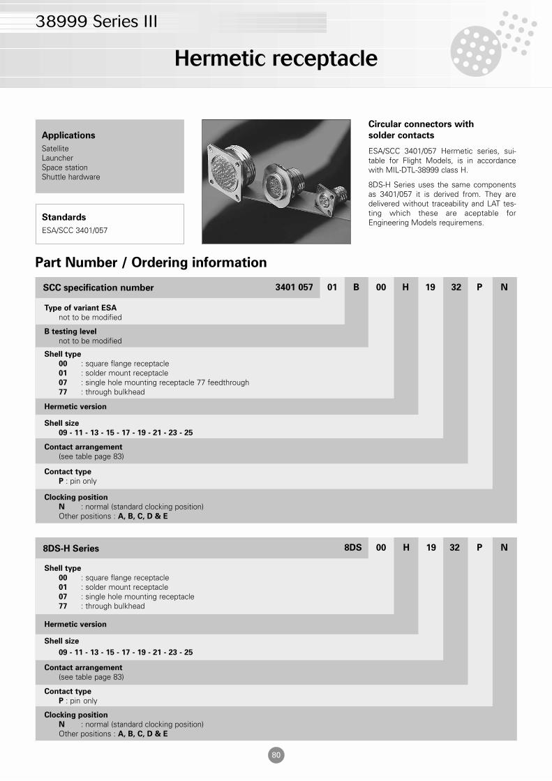
Clocking position
N : normal (standard clocking position)Other positions : A, B, C, D & E
Contact type
P : pin only
Circular connectors with
solder contacts
ESA/SCC 3401/057 Hermetic series, sui-table for Flight Models, is in accordancewith MIL-DTL-38999 class H.
8DS-H Series uses the same componentsas 3401/057 it is derived from. They aredelivered without traceability and LAT tes-ting which these are aceptable forEngineering Models requiremens.
Applications
SatelliteLauncherSpace stationShuttle hardware
Standards
ESA/SCC 3401/057
Contact arrangement
(see table page 83)
Shell size
09 - 11 - 13 - 15 - 17 - 19 - 21 - 23 - 25
Hermetic version
Shell type
00 : square flange receptacle01 : solder mount receptacle07 : single hole mounting receptacle 77 feedthrough77 : through bulkhead
B testing level
not to be modified
Type of variant ESA
not to be modified
Part Number / Ordering information
3401 057 01 B 00 H 19 32 P NSCC specification number
Clocking position
N : normal (standard clocking position)Other positions : A, B, C, D & E
Contact type
P : pin only
Contact arrangement
(see table page 83)
Shell size
09 - 11 - 13 - 15 - 17 - 19 - 21 - 23 - 25
Hermetic version
Shell type
00 : square flange receptacle01 : solder mount receptacle07 : single hole mounting receptacle77 : through bulkhead
8DS 00 H 19 32 P N8DS-H Series
Hermetic receptacle
38999 Series III
81
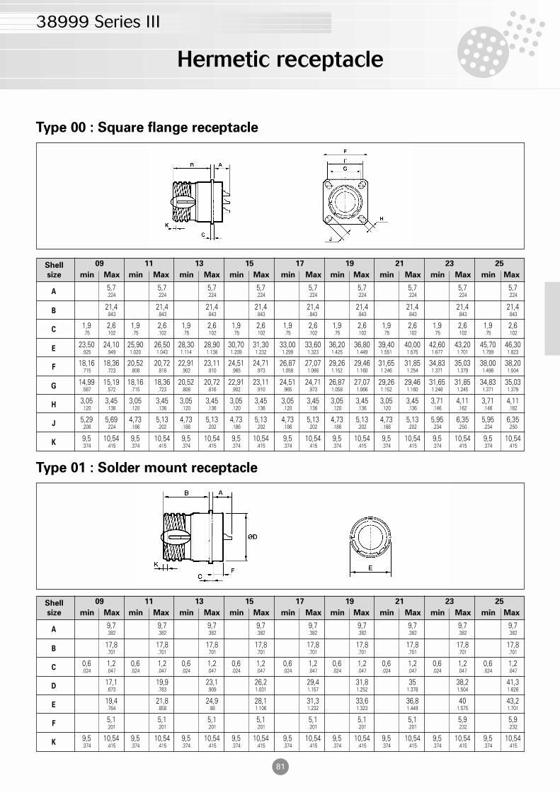
Type 00 : Square flange receptacle
Shell
size min Max min Max min Max min Max min Max min Max min Max min Max min Max
09 11 13 15 17 19 21 23 25
A5,7 5,7 5,7 5,7 5,7 5,7 5,7 5,7 5,7.224 .224 .224 .224 .224 .224 .224 .224 .224
B21,4 21,4 21,4 21,4 21,4 21,4 21,4 21,4 21,4.843 .843 .843 .843 .843 .843 .843 .843 .843
C1,9 2,6 1,9 2,6 1,9 2,6 1,9 2,6 1,9 2,6 1,9 2,6 1,9 2,6 1,9 2,6 1,9 2,6.75 .102 .75 .102 .75 .102 .75 .102 .75 .102 .75 .102 .75 .102 .75 .102 .75 .102
E23,50 24,10 25,90 26,50 28,30 28,90 30,70 31,30 33,00 33,60 36,20 36,80 39,40 40,00 42,60 43,20 45,70 46,30
.925 .949 1.020 1.043 1.114 1.138 1.209 1.232 1.299 1.323 1.425 1.449 1.551 1.575 1.677 1.701 1.799 1.823
G14,99 15,19 18,16 18,36 20,52 20,72 22,91 23,11 24,51 24,71 26,87 27,07 29,26 29,46 31,65 31,85 34,83 35,03
.567 .572 .715 .723 .808 .816 .902 .910 .965 .973 1.058 1.066 1.152 1.160 1.246 1.245 1.371 1.379
H3,05 3,45 3,05 3,45 3,05 3,45 3,05 3,45 3,05 3,45 3,05 3,45 3,05 3,45 3,71 4,11 3,71 4,11.120 .136 .120 .136 .120 .136 .120 .136 .120 .136 .120 .136 .120 .136 .146 .162 .146 .162
J5,29 5,69 4,73 5,13 4,73 5,13 4,73 5,13 4,73 5,13 4,73 5,13 4,73 5,13 5,95 6,35 5,95 6,35.208 .224 .186 .202 .186 .202 .186 .202 .186 .202 .186 .202 .186 .202 .234 .250 .234 .250
K9,5 10,54 9,5 10,54 9,5 10,54 9,5 10,54 9,5 10,54 9,5 10,54 9,5 10,54 9,5 10,54 9,5 10,54.374 .415 .374 .415 .374 .415 .374 .415 .374 .415 .374 .415 .374 .415 .374 .415 .374 .415
F18,16 18,36 20,52 20,72 22,91 23,11 24,51 24,71 26,87 27,07 29,26 29,46 31,65 31,85 34,83 35,03 38,00 38,20
.715 .723 .808 .816 .902 .910 .965 .973 1.058 1.066 1.152 1.160 1.246 1.254 1.371 1.379 1.496 1.504
Type 01 : Solder mount receptacle
Shell
size min Max min Max min Max min Max min Max min Max min Max min Max min Max
09 11 13 15 17 19 21 23 25
A9,7 9,7 9,7 9,7 9,7 9,7 9,7 9,7 9,7.382 .382 .382 .382 .382 .382 .382 .382 .382
B17,8 17,8 17,8 17,8 17,8 17,8 17,8 17,8 17,8.701 .701 .701 .701 .701 .701 .701 .701 .701
C0,6 1,2 0,6 1,2 0,6 1,2 0,6 1,2 0,6 1,2 0,6 1,2 0,6 1,2 0,6 1,2 0,6 1,2.024 .047 .024 .047 .024 .047 .024 .047 .024 .047 .024 .047 .024 .047 .024 .047 .024 .047
D17,1 19,9 23,1 26,2 29,4 31,8 35 38,2 41,3.673 .783 .909 1.031 1.157 1.252 1.378 1.504 1.626
E19,4 21,8 24,9 28,1 31,3 33,6 36,8 40 43,2.764 .858 .98 1.106 1.232 1.323 1.449 1.575 1.701
F5,1 5,1 5,1 5,1 5,1 5,1 5,1 5,9 5,9.201 .201 .201 .201 .201 .201 .201 .232 .232
K9,5 10,54 9,5 10,54 9,5 10,54 9,5 10,54 9,5 10,54 9,5 10,54 9,5 10,54 9,5 10,54 9,5 10,54.374 .415 .374 .415 .374 .415 .374 .415 .374 .415 .374 .415 .374 .415 .374 .415 .374 .415
Hermetic receptacle
38999 Series III
82
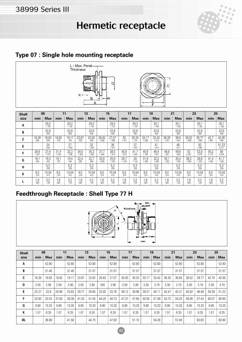
Type 07 : Single hole mounting receptacle
Shell
size min Max min Max min Max min Max min Max min Max min Max min Max min Max
09 11 13 15 17 19 21 23 25
A29,2 29,2 29,3 29,3 29,3 30,1 30,1 30,1 30,11.150 1.150 1.154 1.154 1.154 1.185 1.185 1.185 1.185
B22,6 22,6 22,6 22,6 22,6 22,6 22,6 22,6 22,6.890 .890 .890 .890 .890 .890 .890 .890 .890
C16,38 16,63 18,92 19,17 23,67 23,92 26,82 27,07 30 30,25 33,17 33,42 36,35 36,6 39,52 39,77 42,7 42,95
.645 .645 .745 .755 .932 .942 1.056 1.066 1.181 1.191 1.306 1.316 1.431 1.441 1.556 1.566 1.681 1.691
E24 27 32 36 37 41 46 50 51,23.945 1.063 1.260 1.427 1.457 1.614 1.811 1.969 2.017
G16,1 16,3 19,1 19,4 22,4 22,7 25,6 25,9 28,7 29 31,9 32,2 35,1 35,4 38,3 38,6 41,4 41,7.634 .642 .752 .764 .882 .894 1.008 1.020 1.130 1.142 1.256 1.268 1.382 1.394 1.508 1.520 1.630 1.642
H5,3 5,3 5,3 5,3 5,3 5,3 5,3 5,3 5,3.209 .209 .209 .209 .209 .209 .209 .209 .209
K9,5 10,54 9,5 10,54 9,5 10,54 9,5 10,54 9,5 10,54 9,5 10,54 9,5 10,54 9,5 10,54 9,5 10,54.374 .415 .374 .415 .374 .415 .374 .415 .374 .415 .374 .415 .374 .415 .374 .415 .374 .415
L1,6 3,2 1,6 3,2 1,6 3,2 1,6 3,2 1,6 3,2 1,6 3,2 1,6 3,2 1,6 3,2 1,6 3,2.063 .126 .063 .126 .063 .126 .063 .126 .063 .126 .063 .126 .063 .126 .063 .126 .063 .126
F26,6 27,4 31,4 32,2 34,5 35,3 37,7 38,5 40,9 41,7 45,6 46,4 48,8 49,6 52 52,8 55,2 561.047 1.079 1.236 1.268 1.358 1.390 1.484 1.516 1.610 1.642 1.795 1.827 1.921 1.953 2.047 2.079 2.173 2.205
Hermetic receptacle
38999 Series III
Feedthrough Receptacle : Shell Type 77 H
Shell
size min Max min Max min Max min Max min Max min Max min Max min Max min Max
09 11 13 15 17 19 21 23 25
A 52.80 52.80 52.80 52.80 52.80 52.80 52.80 52.80 52.80
B 31.40 31.40 31.57 31.57 31.57 31.57 31.57 31.57 31.57
C 16.38 16.63 18.92 19.17 23.67 23.92 26.82 27.07 30.00 30.25 33.17 33.42 36.35 36.60 36.52 39.77 42.70 42.95
D 2.50 2.90 2.50 2.90 2.50 2.90 250 2.90 2.50 2.90 3.30 3.70 3.30 3.70 3.30 3.70 3.30 3.70
F 33.00 33.53 37.85 38.38 41.02 41.55 44.20 44.73 47.37 47.90 50.55 51.08 53.72 54.25 56.90 57.43 60.07 60.60
G 9.90 10.20 9.90 10.20 9.90 10.20 9.90 10.20 9.90 10.20 9.90 10.20 9.90 10.20 9.90 10.20 9.90 10.20
K 1.57 6.35 1.57 6.35 1.57 6.35 1.57 6.35 1.57 6.35 1.57 6.35 1.57 6.35 1.57 6.35 1.57 6.35
ØL 36.88 41.58 44.75 47.93 51.10 54.28 57.45 60.63 63.80
E 22.27 22.8 24.99 25.83 29.77 30.60 32.92 33.76 36.12 36.96 39.27 40.11 42.47 43.31 45.62 46.46 50.39 51.23
83
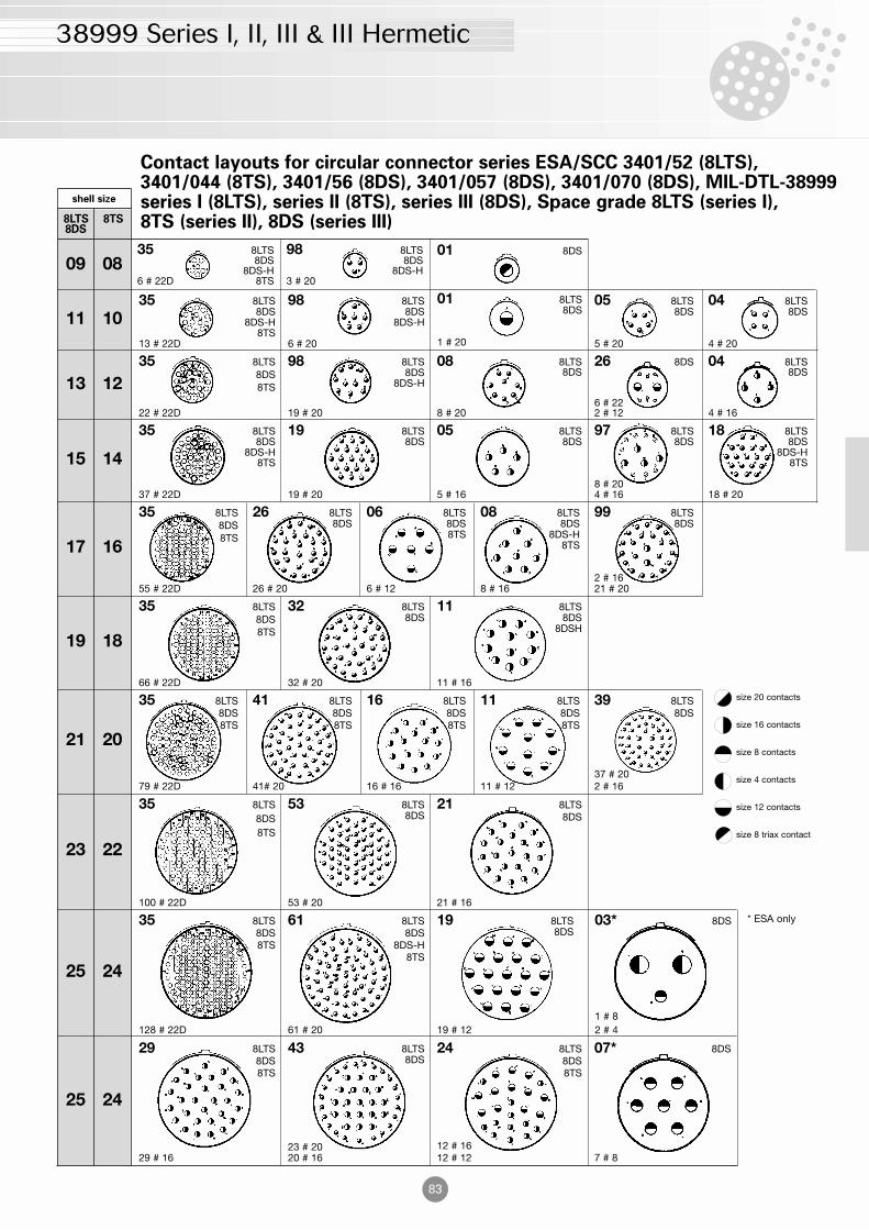
Contact layouts for circular connector series ESA/SCC 3401/52 (8LTS), 3401/044 (8TS), 3401/56 (8DS), 3401/057 (8DS), 3401/070 (8DS), MIL-DTL-38999 series I (8LTS), series II (8TS), series III (8DS), Space grade 8LTS (series I), 8TS (series II), 8DS (series III)
size 20 contacts
size 16 contacts
size 8 contacts
size 4 contacts
size 12 contacts
size 8 triax contact
26 8DS
6 # 222 # 12
01 8LTS8DS
1 # 20
05 8LTS8DS
5 # 20
35 8LTS8DS
8DS-H6 # 22D 8TS
35 8LTS8DS
8DS-H8TS
13 # 22D
35 8LTS8DS8TS
22 # 22D
35 8LTS8DS
8DS-H8TS
37 # 22D
35 8LTS8DS8TS
66 # 22D
35 8LTS8DS8TS
79 # 22D
35 8LTS8DS8TS
100 # 22D
35 8LTS8DS8TS
128 # 22D
29 8LTS8DS8TS
29 # 16
09 08
11 10
21 8LTS8DS
21 # 16
19 8LTS8DS
19 # 12
41 8LTS8DS8TS
41# 20
16 8LTS8DS8TS
16 # 16
39 8LTS8DS
37 # 202 # 16
32 8LTS8DS
32 # 20
11 8LTS8DS
8DSH
11 # 16
99 8LTS8DS
2 # 1621 # 20
98 8LTS8DS
8DS-H3 # 20
98 8LTS8DS
8DS-H
6 # 20
98 8LTS8DS
8DS-H
19 # 20
19 8LTS8DS
19 # 20
08 8LTS8DS
8 # 20
05 8LTS8DS
5 # 16
97 8LTS8DS
8 # 204 # 16
13 12
15 14
17 16
19 18
21 20
23 22
25 24
25 24
shell size
8LTS 8TS8DS
26 8LTS8DS
26 # 20
35 8LTS8DS8TS
55 # 22D
06 8LTS8DS8TS
6 # 12
08 8LTS8DS
8DS-H8TS
8 # 16
04 8LTS8DS
4 # 20
04 8LTS8DS
4 # 16
18 8LTS8DS
8DS-H8TS
18 # 20
11 8LTS8DS8TS
11 # 12
53 8LTS8DS
53 # 20
03* 8DS
1 # 82 # 4
07* 8DS
7 # 8
24 8LTS8DS8TS
12 # 1612 # 12
43 8LTS8DS
23 # 2020 # 16
61 8LTS8DS
8DS-H8TS
61 # 20
* ESA only
01 8DS
38999 Series I, II, III & III Hermetic
84
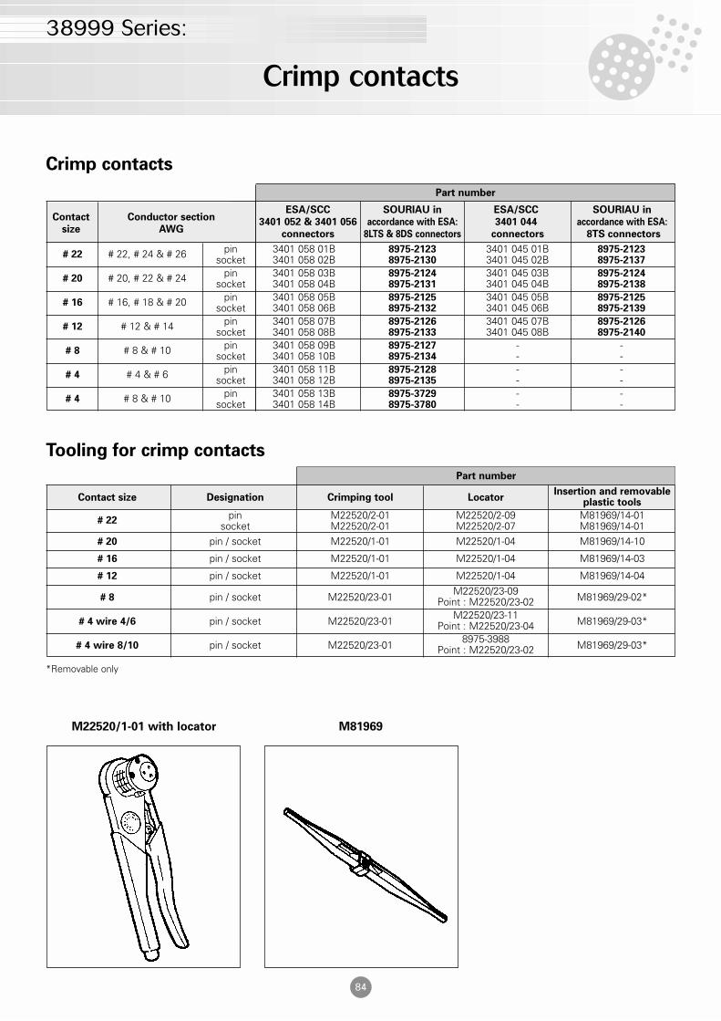
Crimp contacts
Tooling for crimp contacts
Part number
Part number
Contact Conductor sectionESA/SCC SOURIAU in ESA/SCC SOURIAU in
size AWG3401 052 & 3401 056 accordance with ESA: 3401 044 accordance with ESA:
connectors 8LTS & 8DS connectors connectors 8TS connectors
pin 3401 058 01B 8975-2123 3401 045 01B 8975-2123socket 3401 058 02B 8975-2130 3401 045 02B 8975-2137
pin 3401 058 03B 8975-2124 3401 045 03B 8975-2124socket 3401 058 04B 8975-2131 3401 045 04B 8975-2138
pin 3401 058 05B 8975-2125 3401 045 05B 8975-2125socket 3401 058 06B 8975-2132 3401 045 06B 8975-2139
pin 3401 058 07B 8975-2126 3401 045 07B 8975-2126socket 3401 058 08B 8975-2133 3401 045 08B 8975-2140
pin 3401 058 09B 8975-2127 - -socket 3401 058 10B 8975-2134 - -
pin 3401 058 11B 8975-2128 - -socket 3401 058 12B 8975-2135 - -
pin 3401 058 13B 8975-3729 - -socket 3401 058 14B 8975-3780 - -
Contact size Designation Crimping tool LocatorInsertion and removable
plastic tools
# 22pin M22520/2-01 M22520/2-09 M81969/14-01
socket M22520/2-01 M22520/2-07 M81969/14-01# 20 pin / socket M22520/1-01 M22520/1-04 M81969/14-10
# 16 pin / socket M22520/1-01 M22520/1-04 M81969/14-03
# 12 pin / socket M22520/1-01 M22520/1-04 M81969/14-04
# 8 pin / socket M22520/23-01 M22520/23-09 M81969/29-02*Point : M22520/23-02
# 4 wire 4/6 pin / socket M22520/23-01 M22520/23-11 M81969/29-03*Point : M22520/23-04
# 4 wire 8/10 pin / socket M22520/23-01 8975-3988 M81969/29-03*Point : M22520/23-02
# 22 # 22, # 24 & # 26
# 20 # 20, # 22 & # 24
# 16 # 16, # 18 & # 20
# 12 # 12 & # 14
# 8 # 8 & # 10
# 4 # 4 & # 6
# 4 # 8 & # 10
*Removable only
M22520/1-01 with locator M81969
Crimp contacts
38999 Series:
85
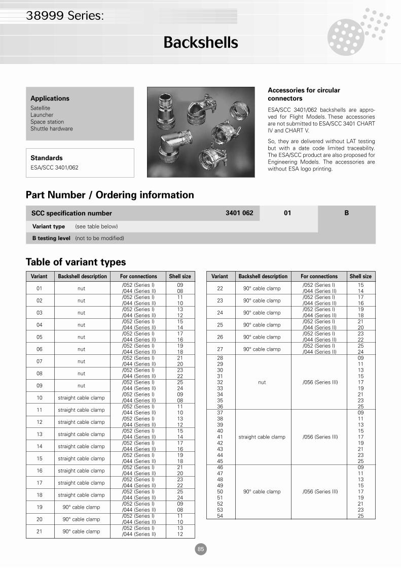
Accessories for circular
connectors
ESA/SCC 3401/062 backshells are appro-ved for Flight Models. These accessoriesare not submitted to ESA/SCC 3401 CHARTIV and CHART V.
So, they are delivered without LAT testingbut with a date code limited traceability.The ESA/SCC product are also proposed forEngineering Models. The accessories arewithout ESA logo printing.
Applications
SatelliteLauncherSpace stationShuttle hardware
Standards
ESA/SCC 3401/062
B testing level (not to be modified)
Variant type (see table below)
Part Number / Ordering information
Table of variant types
3401 062 01 BSCC specification number
Variant Backshell description For connections Shell size
01 nut/052 (Series I) 09/044 (Series II) 08
02 nut/052 (Series I) 11/044 (Series II) 10
03 nut/052 (Series I) 13/044 (Series II) 12
04 nut/052 (Series I) 15/044 (Series II) 14
05 nut/052 (Series I) 17/044 (Series II) 16
06 nut/052 (Series I) 19/044 (Series II) 18
07 nut/052 (Series I) 21/044 (Series II) 20
08 nut/052 (Series I) 23/044 (Series II) 22
09 nut/052 (Series I) 25/044 (Series II) 24
10 straight cable clamp/052 (Series I) 09/044 (Series II) 08
11 straight cable clamp/052 (Series I) 11/044 (Series II) 10
12 straight cable clamp/052 (Series I) 13/044 (Series II) 12
13 straight cable clamp/052 (Series I) 15/044 (Series II) 14
14 straight cable clamp/052 (Series I) 17/044 (Series II) 16
15 straight cable clamp/052 (Series I) 19/044 (Series II) 18
16 straight cable clamp/052 (Series I) 21/044 (Series II) 20
17 straight cable clamp/052 (Series I) 23/044 (Series II) 22
18 straight cable clamp/052 (Series I) 25/044 (Series II) 24
19 90° cable clamp/052 (Series I) 09/044 (Series II) 08
20 90° cable clamp/052 (Series I) 11/044 (Series II) 10
21 90° cable clamp/052 (Series I) 13/044 (Series II) 12
Variant Backshell description For connections Shell size
22 90° cable clamp/052 (Series I) 15/044 (Series II) 14
23 90° cable clamp/052 (Series I) 17/044 (Series II) 16
24 90° cable clamp/052 (Series I) 19/044 (Series II) 18
25 90° cable clamp/052 (Series I) 21/044 (Series II) 20
26 90° cable clamp/052 (Series I) 23/044 (Series II) 22
27 90° cable clamp/052 (Series I) 25/044 (Series II) 24
28 0929 1130 1331 1532 nut /056 (Series III) 1733 1934 2135 2336 2537 0938 1139 1340 1541 straight cable clamp /056 (Series III) 1742 1943 2144 2345 2546 0947 1148 1349 1550 90° cable clamp /056 (Series III) 1751 1952 2153 2354 25
Backshells
38999 Series:
86
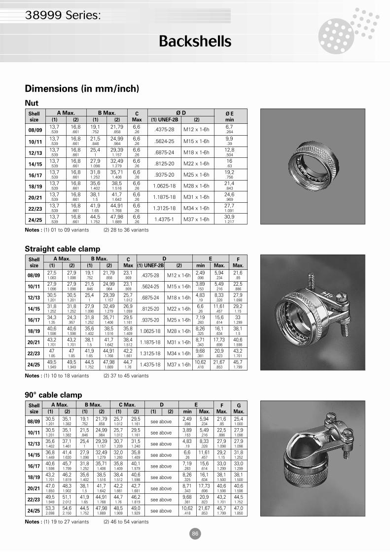
Dimensions (in mm/inch)
Shell C Ø Esize (1) (2) (1) (2) Max (1) UNEF-2B (2) min
A Max. B Max. Ø D
Notes : (1) 01 to 09 variants (2) 28 to 36 variants
Nut
08/0913,7 16,8 19,1 21,79 6,6 .4375-28 M12 x 1-6h 6,7.539 .661 .752 .858 .26 .264
10/1113,7 16,8 21,5 24,99 6,6 .5624-25 M15 x 1-6h 9,9.539 .661 .846 .984 .26 .39
12/1313,7 16,8 25,4 29,39 6,6 .6875-24 M18 x 1-6h 12,8.539 .661 1 1.157 .26 .504
14/1513,7 16,8 27,9 32,49 6,6 .8125-20 M22 x 1-6h 16.539 .661 1.098 1.279 .26 .63
16/1713,7 16,8 31,8 35,71 6,6 .9375-20 M25 x 1-6h 19,2.539 .661 1.252 1.406 .26 .756
18/1913,7 16,8 35,6 38,5 6,6 1.0625-18 M28 x 1-6h 21,4.539 .661 1.402 1.516 .26 .843
20/2113,7 16,8 38,1 41,7 6,6 1.1875-18 M31 x 1-6h 24,6.539 .661 1.5 1.642 .26 .969
22/2313,7 16,8 41,9 44,91 6,6 1.3125-18 M34 x 1-6h 27,7.539 .661 1.65 1.768 .26 1.091
24/2513,7 16,8 44,5 47,98 6,6 1.4375-1 M37 x 1-6h 30,9.539 .661 1.752 1.889 .26 1.217
Shell C Fsize (1) (2) (1) (2) Max (1) UNEF-2B (2) min Max. Max.
A Max. B Max. D E
Notes : (1) 10 to 18 variants (2) 37 to 45 variants
Straight cable clamp
08/0927,5 27,9 19,1 21,79 23,1 .4375-28 M12 x 1-6h 2,49 5,94 21,61.083 1.098 .752 .858 .909 .098 .234 .85
10/1127,9 27,9 21,5 24,99 23,1 .5624-25 M15 x 1-6h 3,89 5,49 22,51.098 1.098 .846 .984 .909 .153 .216 .886
12/1330,5 30,5 25,4 29,39 25,7 .6875-24 M18 x 1-6h 4,83 8,33 27,91.201 1.201 1 1.157 1.012 .19 .328 1.098
14/1531,8 31,8 27,9 32,49 26,9 .8125-20 M22 x 1-6h 6,6 11,61 29,21.252 1.252 1.098 1.279 1.059 .26 .457 1.15
16/1734,3 24,3 31,8 35,71 29,5 .9375-20 M25 x 1-6h 7,19 15,6 331.35 .957 1.252 1.406 1.161 .283 .614 1.299
18/1940,6 40,6 35,6 38,5 35,8 1.0625-18 M28 x 1-6h 8,26 16,1 38,11.598 1.598 1.402 1.516 1.409 .325 .634 1.5
20/2143,2 43,2 38,1 41,7 38,4 1.1875-18 M31 x 1-6h 8,71 17,73 40,61.701 1.701 1.5 1.642 1.512 .343 .698 1.598
22/2347 47 41,9 44,91 42,2 1.3125-18 M34 x 1-6h 9,68 20,9 43,21.85 1.85 1.65 1.768 1.661 .381 .823 1.701
24/2549,5 49,5 44,5 47,98 44,7 1.4375-18 M37 x 1-6h 10,62 21,67 45,71.949 1.949 1.752 1.889 1.76 .418 .853 1.799
Shell F Gsize (1) (2) (1) (2) (1) (2) (1) (2) min Max. Max. Max.
A Max. B Max. C Max. D E
Notes : (1) 19 to 27 variants (2) 46 to 54 variants
90° cable clamp
08/0930,5 35,1 19,1 21,79 25,7 29,5 see above 2,49 5,94 21,6 25,41.201 1.382 .752 .858 1.012 1.161 .098 .234 .85 1.000
10/1130,5 35,1 21,5 24,99 25,7 29,5 see above 3,89 5,49 22,5 27,91.201 1.382 .846 .984 1.012 1.161 .153 .216 .886 1.098
12/1335,6 37,1 25,4 29,39 30,7 31,5 see above 4,83 8,33 27,9 27,91.402 1.461 1 1.157 1.209 1.240 .19 .328 1.098 1.098
14/1536,8 41,4 27,9 32,49 32,0 35,8 see above 6,6 11,61 29,2 31,81.449 1.630 1.098 1.279 1.260 1.409 .26 .457 1.15 1.252
16/1740,6 45,7 31,8 35,71 35,8 40,1 see above 7,19 15,6 33,0 33,01.598 1.799 1.252 1.406 1.409 1.579 .283 .614 1.299 1.299
18/1943,2 46,2 35,6 38,5 38,4 40,6 see above 8,26 16,1 38,1 38,11.701 1.819 1.402 1.516 1.512 1.598 .325 .634 1.500 1.500
20/2147,0 48,3 38,1 41,7 42,2 42,7 see above 8,71 17,73 40,6 40,61.850 1.902 1.5 1.642 1.661 1.681 .343 .698 1.598 1.598
22/2349,5 51,1 41,9 44,91 44,7 46,2 see above 9,68 20,9 43,2 44,51.949 2.012 1.65 1.768 1.76 1.819 .381 .823 1.701 1.752
24/2553,3 54,6 44,5 47,98 48,5 49,0 see above 10,62 21,67 45,7 47,02.098 2.150 1.752 1.889 1.909 1.929 .418 .853 1.799 1.850
Backshells
38999 Series: