Embed Size (px)
Citation preview

S I S T E M I D I S I C U R E Z Z A
GameOver
MANUALE
DI
INSTALLAZIONE
E
PROGRAMMAZIONE
I N S T A L L AT I O N
A N D
P R O G R A M M I N G
M A N U A L
S E C U R I T Y S Y S T E M S
Certified byIMQ - Security systems
CEI 79-2EN 50131-3EN 50131-6T014

2
Installation and Programming Manual
WarrantyINIM Electronics s.r.l. (Seller, Our, Us) warrants the original purchaser that thisproduct shall be free from defects in materials and workmanship under normaluse for a period of 24 months. As INIM Electronics s.r.l. does not install thisproduct directly, and due to the possibility that it may be used with otherequipment not approved by Us; INIM Electronics s.r.l. does not warrant againstloss of quality, degradation of performance of this product or actual damage thatresults from the use of products, parts or other replaceable items (such asconsumables) that are neither made nor recommended by INIM Electronics.Seller obligation and liability under this warranty is expressly limited to repairingor replacing, at Seller's option, any product not meeting the specifications. In noevent shall INIM Electronics s.r.l. be liable to the purchaser or any other personfor any loss or damage whether direct ot indirect or consequential or incidental,including without limitation, any damages for lost profits, stolen goods, or claimsby any other party caused by defective products or otherwise arising from theincorrect or otherwise improper installation or use of this product.
This warranty applies only to defects in parts and workmanship relating to normaluse. It does not cover:
• damage arising from improper maintenance or negligence• damage caused by fire, flood, wind or lightning• vandalism• fair wear and tearINIM Electronics s.r.l. shall, at its option, repair or replace any defective products.Improper use, that is, use for purposes other than those mentioned in thismanual will void the warranty. Contact Our authorized dealer, or visit our websitefor further information regarding this warranty.
Limited Warranty
INIM Electronics s.r.l. shall not be liable to the purchaser or any other person fordamage arising from improper storage, handling or use of this product.
Installation of this Product must be carried out by qualified persons appointed byINIM Electronics. Installation of this Product must be carried out in accordancewith Our instructions in the product manual.
CopyrightThe information contained in this document is the sole property of INIMElectronics s.r.l. No part may be copied without written authorization from INIMElectronics s.r.l.
All rights reserved.
European Directive compliance
Hereby INIM Electronics s.r.l. declares that the SmartLiving series of intrusion-control panels, the Air2 series of devices and the SmartLink product are incompliance with the essential requirements and other relevant provisions ofDirective 1999/5/CE.
Moreover, INIM Electronics s.r.l. also declares that all other devices mentioned inthis manual are in compliance with the essential requirements and other relevantprovisions of Directive 2004/108/CE.
The full declarations of conformity can be found at URL: www.inim.biz/dc.html.
State-of-the-art Installations (DM 37/08)
The devices described in this manual, in accordance with the settings selectedduring the installation phase and the following illustrated guidelines are,alternatively, in compliance with the the Italian Normative CEI 79-2:1998+Ab:2000performance level 2 or European Normative CEI EN 50131-3:2009 (in reference toControl and indicating equipment - intrusion control panels) and CEI EN 50131-6:2008 (in reference to Power supplies) security grade 2.
In support of research, development, installation, testing, commissioning andmaintenance of intrusion alarm systems installed in buildings please refer to thefollowing normative documents:
CEI 79-3 e CEI CLC/TS 50131-7.
When installing INIM systems, it is up to the installer company to install systemsequipped with Normative CEI 79-2 compliant devices rather than devicescompliant with European Normatives series EN50131 within and not over theDOWs summarized in amendment CEI 79-2;V1:2010.

Installation and Programming Manual
3
Table of contents
Warranty . . . . . . . . . . . . . . . . . . . . . . . . . . . . . . . . . . . . . . . 2Limited Warranty . . . . . . . . . . . . . . . . . . . . . . . . . . . . . . . . . 2Copyright . . . . . . . . . . . . . . . . . . . . . . . . . . . . . . . . . . . . . . 2European Directive compliance. . . . . . . . . . . . . . . . . . . . . . . . 2State-of-the-art Installations (DM 37/08) . . . . . . . . . . . . . . . . 2Table of contents . . . . . . . . . . . . . . . . . . . . . . . . . . . . . . . . . 3
About this manual . . . . . . . . . . . . . . . . . . . . . . . . . . 50-1 Terminology . . . . . . . . . . . . . . . . . . . . . . . . . . . . . . . . . . . . . . . . . 50-2 Graphic conventions. . . . . . . . . . . . . . . . . . . . . . . . . . . . . . . . . . . . 5
Chapter 1 General information . . . . . . . . . . . . . . . . . . . . . . . . . 61-1 Manufacturer's details . . . . . . . . . . . . . . . . . . . . . . . . . . . . . . . . . . 61-2 Description of the product and various models . . . . . . . . . . . . . . . . . 61-3 Products certified and conforming to directives . . . . . . . . . . . . . . . . . 61-4 Patents Pending. . . . . . . . . . . . . . . . . . . . . . . . . . . . . . . . . . . . . . . 71-5 Manuals . . . . . . . . . . . . . . . . . . . . . . . . . . . . . . . . . . . . . . . . . . . . 81-6 Operator Qualifications . . . . . . . . . . . . . . . . . . . . . . . . . . . . . . . . . . 81-7 Access Levels . . . . . . . . . . . . . . . . . . . . . . . . . . . . . . . . . . . . . . . . 81-8 Conventions – Glossary . . . . . . . . . . . . . . . . . . . . . . . . . . . . . . . . . 8
Chapter 2 The control panel and peripherals. . . . . . . . . . . . . . . . 92-1 Environmental Conditions . . . . . . . . . . . . . . . . . . . . . . . . . . . . . . . . 92-2 SmartLiving intrusion control panels . . . . . . . . . . . . . . . . . . . . . . . . 92-3 Peripherals . . . . . . . . . . . . . . . . . . . . . . . . . . . . . . . . . . . . . . . . . . 13
Chapter 3 Installation . . . . . . . . . . . . . . . . . . . . . . . . . . . . . . . 193-1 Installing the control panel . . . . . . . . . . . . . . . . . . . . . . . . . . . . . . . 193-2 Connecting peripherals . . . . . . . . . . . . . . . . . . . . . . . . . . . . . . . . . 243-3 Addressing the peripherals . . . . . . . . . . . . . . . . . . . . . . . . . . . . . . . 283-4 Auto-enrolling peripherals. . . . . . . . . . . . . . . . . . . . . . . . . . . . . . . . 303-5 Wiring and balancing alarm detectors. . . . . . . . . . . . . . . . . . . . . . . . 303-6 Wiring and balancing rollerblind/shock sensors . . . . . . . . . . . . . . . . . 323-7 Connecting wireless detectors . . . . . . . . . . . . . . . . . . . . . . . . . . . . . 333-8 Learn Zone Balancing. . . . . . . . . . . . . . . . . . . . . . . . . . . . . . . . . . . 333-9 Connecting the outputs . . . . . . . . . . . . . . . . . . . . . . . . . . . . . . . . . 33
3-10 Attachment boards . . . . . . . . . . . . . . . . . . . . . . . . . . . . . . . . . . . . 34
Chapter 4 First power up . . . . . . . . . . . . . . . . . . . . . . . . . . . . . 37
Chapter 5 Installation project via SmartLeague software . . . . . . . 385-1 The SmartLeague software programme . . . . . . . . . . . . . . . . . . . . . . 385-2 Using the software programme . . . . . . . . . . . . . . . . . . . . . . . . . . . . 395-3 Creating a Project layout . . . . . . . . . . . . . . . . . . . . . . . . . . . . . . . . 39
Chapter 6 Options and programming methods . . . . . . . . . . . . . . 416-1 Introduction . . . . . . . . . . . . . . . . . . . . . . . . . . . . . . . . . . . . . . . . . 416-2 Programming from a keypad (accessing the installer menu) . . . . . . . . 41

4
Installation and Programming Manual
6-3 Programming via the SmartLeague programme . . . . . . . . . . . . . . . . 426-4 Panel options . . . . . . . . . . . . . . . . . . . . . . . . . . . . . . . . . . . . . . . . 426-5 Terminals . . . . . . . . . . . . . . . . . . . . . . . . . . . . . . . . . . . . . . . . . . . 446-6 Zones . . . . . . . . . . . . . . . . . . . . . . . . . . . . . . . . . . . . . . . . . . . . . 466-7 Outputs . . . . . . . . . . . . . . . . . . . . . . . . . . . . . . . . . . . . . . . . . . . . 506-8 Telephone . . . . . . . . . . . . . . . . . . . . . . . . . . . . . . . . . . . . . . . . . . 516-9 Events . . . . . . . . . . . . . . . . . . . . . . . . . . . . . . . . . . . . . . . . . . . . . 52
6-10 Timer . . . . . . . . . . . . . . . . . . . . . . . . . . . . . . . . . . . . . . . . . . . . . . 596-11 Partitions . . . . . . . . . . . . . . . . . . . . . . . . . . . . . . . . . . . . . . . . . . . 606-12 User Codes . . . . . . . . . . . . . . . . . . . . . . . . . . . . . . . . . . . . . . . . . . 616-13 Installer codes . . . . . . . . . . . . . . . . . . . . . . . . . . . . . . . . . . . . . . . 636-14 Keys . . . . . . . . . . . . . . . . . . . . . . . . . . . . . . . . . . . . . . . . . . . . . . 636-15 Arming scenarios. . . . . . . . . . . . . . . . . . . . . . . . . . . . . . . . . . . . . . 656-16 Shortcuts . . . . . . . . . . . . . . . . . . . . . . . . . . . . . . . . . . . . . . . . . . . 656-17 Expansions . . . . . . . . . . . . . . . . . . . . . . . . . . . . . . . . . . . . . . . . . . 666-18 Keypads . . . . . . . . . . . . . . . . . . . . . . . . . . . . . . . . . . . . . . . . . . . . 666-19 Readers . . . . . . . . . . . . . . . . . . . . . . . . . . . . . . . . . . . . . . . . . . . . 676-20 Sounders . . . . . . . . . . . . . . . . . . . . . . . . . . . . . . . . . . . . . . . . . . . 686-21 Language . . . . . . . . . . . . . . . . . . . . . . . . . . . . . . . . . . . . . . . . . . . 686-22 Messages . . . . . . . . . . . . . . . . . . . . . . . . . . . . . . . . . . . . . . . . . . . 696-23 Default settings. . . . . . . . . . . . . . . . . . . . . . . . . . . . . . . . . . . . . . . 696-24 User functions. . . . . . . . . . . . . . . . . . . . . . . . . . . . . . . . . . . . . . . . 716-25 Other parameters . . . . . . . . . . . . . . . . . . . . . . . . . . . . . . . . . . . . . 726-26 Programming the Nexus . . . . . . . . . . . . . . . . . . . . . . . . . . . . . . . . . 74
Chapter 7 Errors and faults . . . . . . . . . . . . . . . . . . . . . . . . . . . 787-1 Faults detected by the control panel . . . . . . . . . . . . . . . . . . . . . . . . 787-2 Communication BUS (I-BUS) . . . . . . . . . . . . . . . . . . . . . . . . . . . . . 797-3 LED activity . . . . . . . . . . . . . . . . . . . . . . . . . . . . . . . . . . . . . . . . . 797-4 Ring Sensitivity . . . . . . . . . . . . . . . . . . . . . . . . . . . . . . . . . . . . . . . 80
Appendix A Technical terminology and Glossary . . . . . . . . . . . . . . 81
Appendix B Shortcuts at default . . . . . . . . . . . . . . . . . . . . . . . . . 89
Appendix C Available icons. . . . . . . . . . . . . . . . . . . . . . . . . . . . . 90
Appendix D Voice messages . . . . . . . . . . . . . . . . . . . . . . . . . . . . 91
Appendix E Screw Terminals . . . . . . . . . . . . . . . . . . . . . . . . . . . 93
Appendix F Combination of outputs triggered by events . . . . . . . . 94
Appendix G Compliancy with the regulations in force. . . . . . . . . . . 95
Appendix H Order Codes . . . . . . . . . . . . . . . . . . . . . . . . . . . . . . 97Notes . . . . . . . . . . . . . . . . . . . . . . . . . . . . . . . . . . . . . . . . . 99

Installation and Programming Manual
About this manual 5
ABOUT THISMANUAL
MANUAL CODEDCMIINE0SLIVINGE
VERSION4.10
0-1TerminologyCONTROL PANEL, SYSTEM, APPARATUS
The main supervisory unit and any constituent parts of the SmartLiving intrusioncontrol system.
LEFT, RIGHT, BEHIND, ABOVE, BELOW
Directions as seen by the operator when directly in front of the mounted device.
DIALERA device which sends voice calls or digital reports to programmed contactnumbers in the event of an alarm.
QUALIFIED PERSONNELPersons whose training, expertise and knowledge of the products and lawsregarding security systems, are able to create, in accordance with therequirements of the purchaser, the most suitable solution for the protectedpremises.
SELECTClick on a specific item on the interface (from drop-down menu, options box,graphic object, etc.).
PRESSClick on a video button, or push a key on the control-panel keypad.
0-2Graphic conventionsFollowing are the graphic conventions used in this manual.
NoteThe “Note” sections contain important information relating to the text.
ATTENTION!The “Attention” prompts indicate that total or partial disregard of the procedurecould damage the device or its peripherals.
DANGER!The “DANGER” warnings indicate that total or partial disregard of the procedurecould injure the operator or persons in the vicinity.
Similarly marked dialogue boxes contain recommendations and/or guidelineswhich the manufacturer wishes to call attention to.
Conventions Example Description
Text in italics Refer to paragraph 4.3 Unpacking the device
Indicates the title of a chapter, section, paragraph, table or figure in this manual or other published reference.
<text> #<AccountCode> Editable field
[Uppercase letter] or [number] [A] or [1]
Reference relating to a part of the system or video
object.
BUTTON , , Keypad keys
Info

6 General information
Installation and Programming Manual
Chapter 1
GENERALINFORMATION
1-1Manufacturer's detailsManufacturer: INIM Electronics s.r.l.Production plant: Via Fosso Antico - Centobuchi
63076 Monteprandone (AP) - ItalyTel: +39 0735 705007Fax: +39 0735 704912e-mail: [email protected]: www.inim.bizAny persons authorized by the manufacturer to repair or replace the parts of thissystem, hold authorization to work on INIM Electronics brand devices only.
1-2Description of the productand various models
Description: Intrusion control panelModels: SmartLiving 505
SmartLiving 515SmartLiving 1050SmartLiving 1050LSmartLiving 10100L
Applied Normative: CEI 79-2:1998+Ab:2000, CEI EN 50131-3:2009 andCEI EN 50131-6:2008
Certification agency: IMQ Security SystemsSecurity rating: 2
1-3Products certified andconforming to directives
The SmartLiving intrusion control panel and the devices described in this manualhave been certified by the IMQ - Security Systems agency as compliant with CEI79-2:1998+Ab:2000, CEI EN 50131-3:2009 and CEI EN 50131-6:2008, whenduly programmed, as described in Appendix G, Compliancy with the regulationsin force.The Control panel enclosure houses the following certified devices:• INIM Electronics switching-power supply• Motherboard (IN082 or IN088)• SmartLogos30M voice board (accessory item)• FLEX5/U input/output expansion board (accessory item)• AUXREL32 relay board (accessory item)• SmartLAN/SI and SmartLAN/G LAN interface boards (accessory items)• IB100/RU BUS isolator board (accessory item)• ProbeTH thermal-probe kit for battery-charge optimization (accessory item)• TamperNO tamper-protection kit (accessory item)• Backup battery, 12 V @ 17 Ah

Installation and Programming Manual
General information 7
• Motherboard (IN082 and IN088) integrated Type B notification apparatusThe control panel compliancy is also guaranteed when connected to the followingcertified devices:• FLEX5/P input/output expansion boards• Joy/MAX, Joy/GR, Concept/G, nCode/G keypads• nBy/S outdoor-mount proximity readers• nBy/X universal-mount proximity readers• IB100/RP BUS isolator• Self-powered IB100/A BUS isolator• nCard access-control card for proximity readers• nTag access-control tag for proximity readersCompliancy is not guaranteed when the control panel is connected to thefollowing uncertified devices:• SmartLink/GWB GSM interface with 12V @ 1.2 Ah battery• BUS-connected Nexus interface• BUS connectable Ivy-B, Ivy-BF, Ivy-BM, and Ivy-BFM self-powered
sounderflashers for outdoor installation• Wireless devices such as: AIR2, AIR2-BS100 (transceivers), Air2-IR100 (PIR
detectors), Air2-MC100 (magnetic contacts), Air2-KF100 (access-controlkeyfobs)
• SmartModem100 Teleservice modem
TYPE B NOTIFICATION APPARATUS
ATS2 notification apparatus (refer to EN50131-1:2008-02, paragraph 8.6Notification, Table 10, page 46, Grade 2 and EN50136) characterized by:• Transmission time - classification D2 (60 seconds)• Transmission time - max. values M2 (120 seconds)• Classification time - classification T2 (25 hours)• S0 Substitution security (no detection of device substitution)• I0 Information security (no detection of message substitution)
1-4Patents PendingThe SmartLiving series of control panels employs the following INIM-patentedtechnologies.• Input/Output Terminals: each terminal on-board the control panel, JOY
keypads and FLEX5 expansion boards can be configured as either an input oroutput zone (Split terminal technology).
• nBy/X proximity reader: this reader has been especially designed to flush-mount to all models of electrical light-switch backboxes.
• Learn zone balancing: this option allows the control panel to save thebalancing values of all the system zones automatically, thus eliminating thetask of typing them in.

8 General information
Installation and Programming Manual
1-5Manuals
1-5-1Installation andProgramming Manual
(this manual)This Manual (not included in the package) can be purchased from your retailer.You (the installer) should read carefully through it in order to become familiarwith all the components and operating procedures of the SmartLiving system. Inorder to provide adequate protection, the installer must adhere to all themanufacturer's guidelines relating to the active and passive security devices ofthis system. It is the installer's responsibility to inform the system users that,regardless of its capabilities, an intrusion alarm system is not a substitute for thenecessary precautions building occupants must take to prevent intrusion.
1-5-2User's ManualThe installer should read carefully through the User's Manual (supplied with eachcontrol panel). Once the system has been installed, you must ensure that theUser's Manual is available to the users for consultation, and that they fullyunderstand how the system works and are aware of all the functions, settingsand procedures.
1-6Operator Qualifications
1-6-1InstallerThe installer is the person (or group of persons) who sets up and programs theentire security system in accordance with the purchaser's requirements and inrespect of the safety laws in force. As the only individual in contact with systemusers, it is the installer's responsibility to instruct them on how to use thesecurity system properly.Under normal circumstances, the installer is not allowed to arm/disarm thesystem without previous authorization from the user. All the system partitionsmust be disarmed before accessing the parameter programming phase.
1-6-2UserThe users are the occupants of the building where this intrusion control panel isinstalled. Only authorized users can access and operate the system.The most common operations can be carried out without code/key verification.This operating method must be expressly requested by the main user, as itconsiderably lowers the security level of the system and may cause false alarms,accidental arm/disarm operations, etc.
1-7Access LevelsThe normative defines the following system-access levels, regardless of system-access limitations:• Level 1 - access by any person (e.g. passer-by)• Level 2 - user access• Level 3 - installer or maintenance operator access (authorized by user - level
2)• Level 4 - manufacturer access
1-8Conventions – GlossaryIn order to understand the terminology utilized in this manual and improve yourknowledge of this system and its operating procedures, read carefully throughthe Technical Terminology – Glossary (refer to Appendix A, Technical terminologyand Glossary).The appendix contains the definitions of technical terms commonly used in thefield of security, therefore, relevant to the SmartLiving system.

Installation and Programming Manual
The control panel and peripherals 9
Chapter 2
THE CONTROL PANELAND PERIPHERALS
2-1Environmental ConditionsAll control panels from the SmartLiving series are for indoor installation only andoperate best under the following conditions:• Temperature: from -10° to +40°C• Maximum humidity: 75% (without condensation)• Environmental class: IIThe JOY/GR, JOY/MAX, nCode/G, Concept/G, IB100, FLEX5, Nexus and nBy/X arefor indoor installation only and operate best under the following environmentalconditions:• Temperature: from -10° to +40°C• Maximum humidity: 75% (without condensation)• Environmental class: IIThe nBy/S reader is suitable for indoor and outdoor installation, and operatesbest under the following conditions:• Temperature: from -25° to +70°C• Maximum humidity: 93% (without condensation)• Protection grade: IP34• Environmental class: IV
2-2SmartLiving intrusioncontrol panels
2-2-1Package contentsInside the package you will find:• Metal enclosure containing the wired motherboard and power supply (adapter
or switching-power supply)• User's Manual• Quick Installation Guide• Plastic bag:
Items not included in the package:Thermal probe (battery-charge optimizer which operates in accordance with thebattery temperature), backup battery, SmartLeague programme CD, InstallationManual. These devices are accessory items which must be purchased separately.
Table 1: Package contents505 515 1050 1050L 10100L
3k9W 1/4W Resistors 10 206k8W 1/4W Resistors 10 20150 Vrms Varistors 2Backup-battery wire 1Screws to secure the
frontplate of the metal enclosure
4
“INIM Electronics security-protected area”
sticker1
Securitysystem
protectedarea

10 The control panel and peripherals
Installation and Programming Manual
2-2-2Control panel descriptions
Compliancy with EN 50131, CEI 79 or CEB T014 requires that the values of themaximum distributable current respect determined limits, as indicated inparagraph 3-1-3 Maximum current - normative references.The control panel label (see figure opposite) is located inside the enclosure.The following table shows the maximum number of devices supported by thevarious control panel models.
NoteSmartLiving control panels are not equipped with built-in dislodgement-tampermicroswitches. For the order code of this accessory item, refer to Appendix H, OrderCodes.
Table 2: Control panels - electrical specifications and mechanical featuresSmartLiving intrusion control panels
505 515 1050 1050L 10100LPower supply voltage 230V ~ -15% +10% 50/60Hz
Nominal output voltage 13.8VVoltage - operating range 9 - 16 VMaximum current draw 0.2A 0.4A 0.6A
Current draw of control panel motherboard 110mA @ 22V~ 75mA @ 13.8V=Maximum distributable current @ 12V 1.2A 3A 5A
Maximum distributable current to open-collector outputs 150mA 500mA
Maximum power-supply voltage ripple 340mV 70mVMax. battery-charge current 1A 2A
Backup battery12V 7Ah 12V 17Ah
recharged 80% in 24h
Max. current across +AUX terminals 900mA 4.05A(1.35A for +AUX1, 1.35A for +AUX2, 1.35A for +AUX3)
Power supply (EN 50131) Type AEnclosure Dimensions (W x H x D) 21.5 x 30.5 x 8.5cm 37.5 x 51 x 8.5cm
Weight (without battery) 2.5 Kg 2.2 Kg 5.3 Kg
Table 3: Control panel - Main Features505 515 1050 1050L 10100L
Total terminals 5 15 50 100Terminals on panel 5 10
Terminals on panel configurable as inputs 5 10
Terminals on panel configurable as Rollerblind/Shock 2
Terminals on panel configurable as outputs 0 5
Total zones 10 30 100 200Outputs on control-panel PCB 3
Relay outputs on control-panel PCB 1Open-collector outputs 2
Partitions 5 10 15Keypads
(JOY, nCode/G, Concept/G) 5 10 15
Voice memo slots 5 10 15FLEX5 expansions 5 10 20 40
nBy Readers 10 20 30TransceiversAir2-BS100 10 20 30
Digital keys and keyfobs 50 100 150Possible key combinations 4294967296
IB100 isolators 15Nexus dialer 1
Codes 30 50 100Scenarios 30
Timer 10 20Recordable events 500 1000
Programmable events 10 30 50
Alimentazione / Power
LBD
TIN
4AS
LIV
05
I
230V~ -15% + 10%Tension / Alimentacion 50/60 HzConsumo / Consumption Consommation / Consumo 0.2 A
Classe ambientale / Environmental classClasse d'environnement / Clase ambiental
MADE IN ITALY
Classe di Isolamento / Insulation classInsulation class / Clase aislante
II
EN 50131-3 grade 2EN 50131-6 grade 2CEI 79-2 livello 2CEB T014
505 01/2011
Alimentazione / Power
LBD
TIN
4AS
LIV
15
I
230V~ -15% + 10%Tension / Alimentacion 50/60 HzConsumo / Consumption Consommation / Consumo 0.2 A
Classe ambientale / Environmental classClasse d'environnement / Clase ambiental
Classe di Isolamento / Insulation classInsulation class / Clase aislante
II
EN 50131-3 grade 2EN 50131-6 grade 2CEI 79-2 livello 2CEB T014
515 01/2011
MADE IN ITALY
C0280518
Alimentazione / Power
LBD
TIN
4AS
LIV
50I
230V~ -15% + 10%Tension / Alimentacion 50/60 HzConsumo / Consumption Consommation / Consumo 0.4 A
Classe ambientale / Environmental classClasse d'environnement / Clase ambiental
Classe di Isolamento / Insulation classInsulation class / Clase aislante
II
EN 50131-3 grade 2EN 50131-6 grade 2CEI 79-2 livello 2CEB T014
1050 01/2011
MADE IN ITALY
C0280517
Alimentazione / Power
LBD
TIN
4AS
LIV
50L
I
230V~ -15% + 10%Tension / Alimentacion 50/60 HzConsumo / Consumption Consommation / Consumo 0.4 A
Classe ambientale / Environmental classClasse d'environnement / Clase ambiental
Classe di Isolamento / Insulation classInsulation class / Clase aislante
II
EN 50131-3 grade 2EN 50131-6 grade 2CEI 79-2 livello 2CEB T014
1050L01/2011
MADE IN ITALY
C0280517
Alimentazione / Power
LBD
TIN
4AS
LIV
100L
I
230V~ -15% + 10%Tension / Alimentacion 50/60 HzConsumo / Consumption Consommation / Consumo 0.6 A
Classe ambientale / Environmental classClasse d'environnement / Clase ambiental
Classe di Isolamento / Insulation classInsulation class / Clase aislante
II
EN 50131-3 grade 2EN 50131-6 grade 2CEI 79-2 livello 2CEB T014
10100L01/2011
MADE IN ITALY
C0280517
Installation and Programming Manual
The control panel and peripherals 11
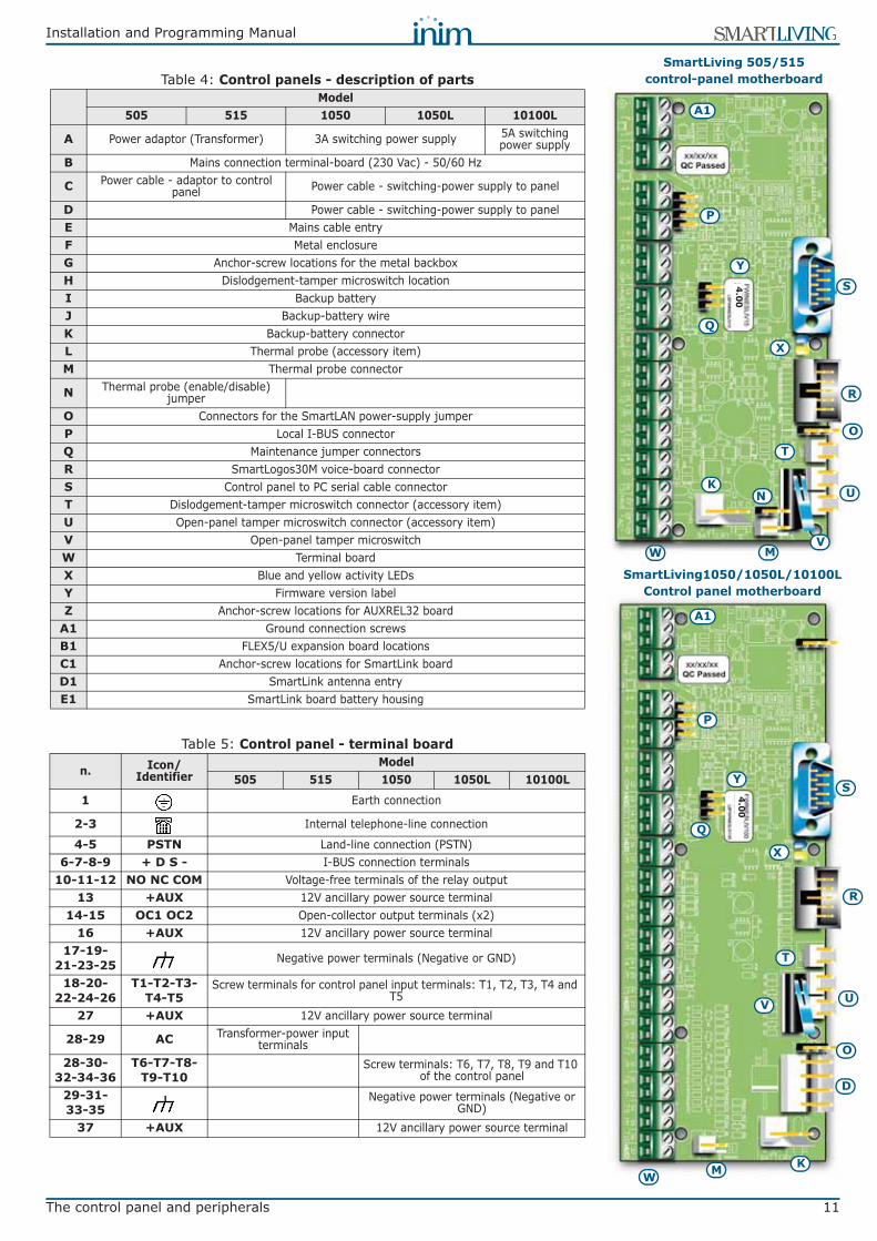
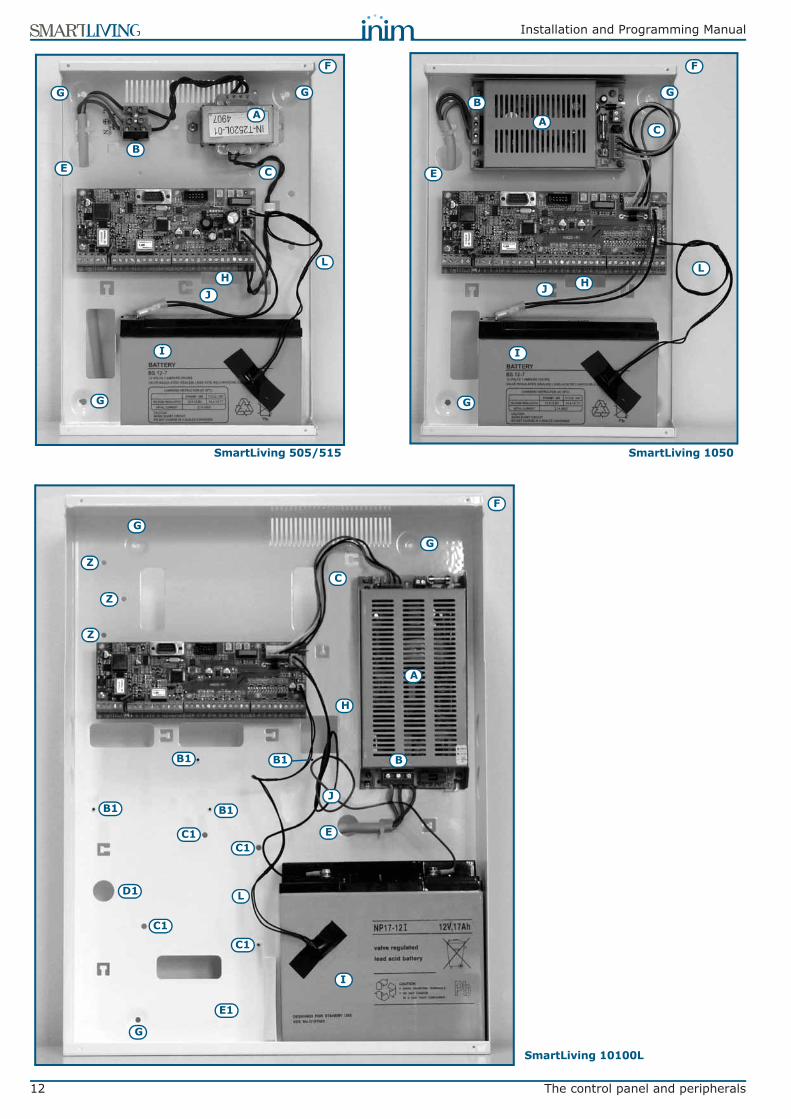
Table 4: Control panels - description of partsModel
505 515 1050 1050L 10100L
A Power adaptor (Transformer) 3A switching power supply 5A switching power supply
B Mains connection terminal-board (230 Vac) - 50/60 Hz
C Power cable - adaptor to control panel Power cable - switching-power supply to panel
D Power cable - switching-power supply to panelE Mains cable entryF Metal enclosureG Anchor-screw locations for the metal backboxH Dislodgement-tamper microswitch locationI Backup batteryJ Backup-battery wireK Backup-battery connectorL Thermal probe (accessory item)M Thermal probe connector
N Thermal probe (enable/disable) jumper
O Connectors for the SmartLAN power-supply jumperP Local I-BUS connector Q Maintenance jumper connectorsR SmartLogos30M voice-board connectorS Control panel to PC serial cable connectorT Dislodgement-tamper microswitch connector (accessory item)U Open-panel tamper microswitch connector (accessory item)V Open-panel tamper microswitchW Terminal boardX Blue and yellow activity LEDsY Firmware version labelZ Anchor-screw locations for AUXREL32 board
A1 Ground connection screwsB1 FLEX5/U expansion board locationsC1 Anchor-screw locations for SmartLink boardD1 SmartLink antenna entryE1 SmartLink board battery housing
Table 5: Control panel - terminal board
n. Icon/Identifier
Model505 515 1050 1050L 10100L
1 Earth connection
2-3 Internal telephone-line connection
4-5 PSTN Land-line connection (PSTN)6-7-8-9 + D S - I-BUS connection terminals
10-11-12 NO NC COM Voltage-free terminals of the relay output13 +AUX 12V ancillary power source terminal
14-15 OC1 OC2 Open-collector output terminals (x2)16 +AUX 12V ancillary power source terminal
17-19-21-23-25 Negative power terminals (Negative or GND)
18-20-22-24-26
T1-T2-T3-T4-T5
Screw terminals for control panel input terminals: T1, T2, T3, T4 and T5
27 +AUX 12V ancillary power source terminal
28-29 AC Transformer-power input terminals
28-30-32-34-36
T6-T7-T8-T9-T10
Screw terminals: T6, T7, T8, T9 and T10 of the control panel
29-31-33-35
Negative power terminals (Negative or GND)
37 +AUX 12V ancillary power source terminal
D
KMW
O
S
R
T
V U
Q
P
K
W M
T
U
V
S
Q
Y
P
Y
X
N
X
O
A1
A1
R
SmartLiving 505/515 control-panel motherboard
SmartLiving1050/1050L/10100LControl panel motherboard
4.00
4.00
12 The control panel and peripherals
Installation and Programming Manual
A
B
CE
I
F
G
G G
L
JH
A
B
C
E
I
F
GG
G
J
L
Z
Z
Z
B1
B1 B1
B1
C1C1
C1
C1
E1
H
D1
A
B
C
E
I
F
G
G
L
J H
SmartLiving 10100L
SmartLiving 505/515 SmartLiving 1050
Installation and Programming Manual
The control panel and peripherals 13
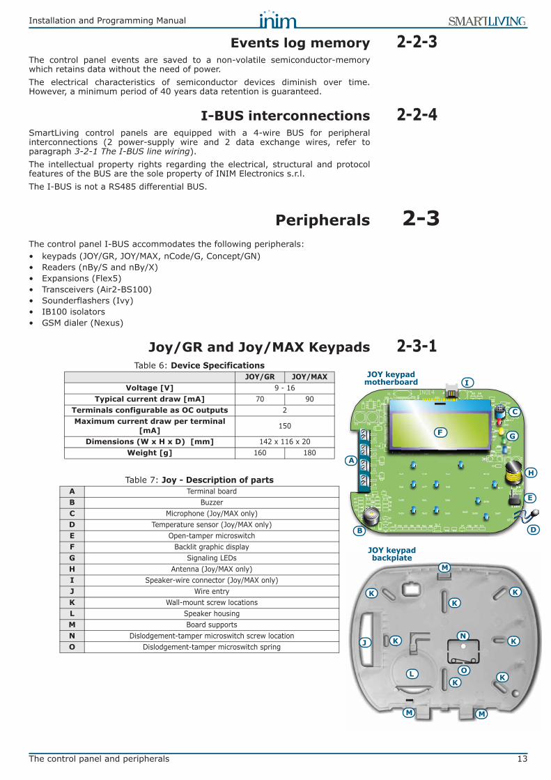
2-2-3Events log memoryThe control panel events are saved to a non-volatile semiconductor-memorywhich retains data without the need of power.The electrical characteristics of semiconductor devices diminish over time.However, a minimum period of 40 years data retention is guaranteed.
2-2-4I-BUS interconnectionsSmartLiving control panels are equipped with a 4-wire BUS for peripheralinterconnections (2 power-supply wire and 2 data exchange wires, refer toparagraph 3-2-1 The I-BUS line wiring).The intellectual property rights regarding the electrical, structural and protocolfeatures of the BUS are the sole property of INIM Electronics s.r.l.The I-BUS is not a RS485 differential BUS.
2-3PeripheralsThe control panel I-BUS accommodates the following peripherals:• keypads (JOY/GR, JOY/MAX, nCode/G, Concept/GN)• Readers (nBy/S and nBy/X)• Expansions (Flex5)• Transceivers (Air2-BS100)• Sounderflashers (Ivy)• IB100 isolators • GSM dialer (Nexus)
2-3-1Joy/GR and Joy/MAX KeypadsTable 6: Device Specifications
JOY/GR JOY/MAXVoltage [V] 9 - 16
Typical current draw [mA] 70 90Terminals configurable as OC outputs 2Maximum current draw per terminal
[mA] 150
Dimensions (W x H x D) [mm] 142 x 116 x 20Weight [g] 160 180
Table 7: Joy - Description of partsA Terminal boardB BuzzerC Microphone (Joy/MAX only)D Temperature sensor (Joy/MAX only)E Open-tamper microswitchF Backlit graphic displayG Signaling LEDsH Antenna (Joy/MAX only)I Speaker-wire connector (Joy/MAX only)J Wire entryK Wall-mount screw locationsL Speaker housingM Board supportsN Dislodgement-tamper microswitch screw locationO Dislodgement-tamper microswitch spring
A
B
C
E
G
H
K
L
D
F
K
KK
K
KK
M
M M
I
J
O
N
JOY keypad motherboard
JOY keypad backplate

14 The control panel and peripherals
Installation and Programming Manual
Keypad terminals:
Terminals T1 and T2 can be configured as:• Input (also as Rollerblind or Shock)• Output• Double zone• Supervised OutputThe keypad package contains a sticker (to be located under the keypad flip)which can be used to note down the keypad address or label, its location, thepartitions it controls and any phone-contact numbers.
2-3-2nCode/G and Concept/G Keypads
Code/G and Concept/G keypads are equippedwith a buzzer and a T1 terminal which can beconfigured as:• Input (also as Rollerblind or Shock)• Output• Double zone
Table 8: Joy - terminal board
n. Icon/Identifier description
1 + Terminal “+” for the I-BUS connection2 D Terminal “D” for the I-BUS connection3 S Terminal “S” for the I-BUS connection4 - Terminal “-” for the I-BUS connection5 T1 Screw terminal of keypad terminal T1
6 Negative power terminal (Negative or GND)
7 T2 Screw terminal of keypad terminal T2
8 Negative power terminal (Negative or GND)
1 2
3 4
5 6
7 8
A
Table 9: Device SpecificationsnCode/G Concept/G
Voltage [V] 9 - 16Typical current draw [mA] 70 80
Terminals configurable as OC outputs 1Maximum current draw per terminal
[mA] 150
Dimensions (W x H x D) [mm] 87 x 129 x 18Weight [g] 135 155
Table 10: nCode/G and Concept/G - Description of partsA Backlit graphic displayB Signaling LEDsC Cable connectorD Tamper microswitchE Screw locationF Screw locationG Terminal board guideH Buzzer
A
B
nCode/G keypad frontplate
A
B
Concept/G keypad frontplate
C
E
D
F F
F
F F
G
H
G
Retro keypadsnCode/G and Concept/G
Installation and Programming Manual
The control panel and peripherals 15
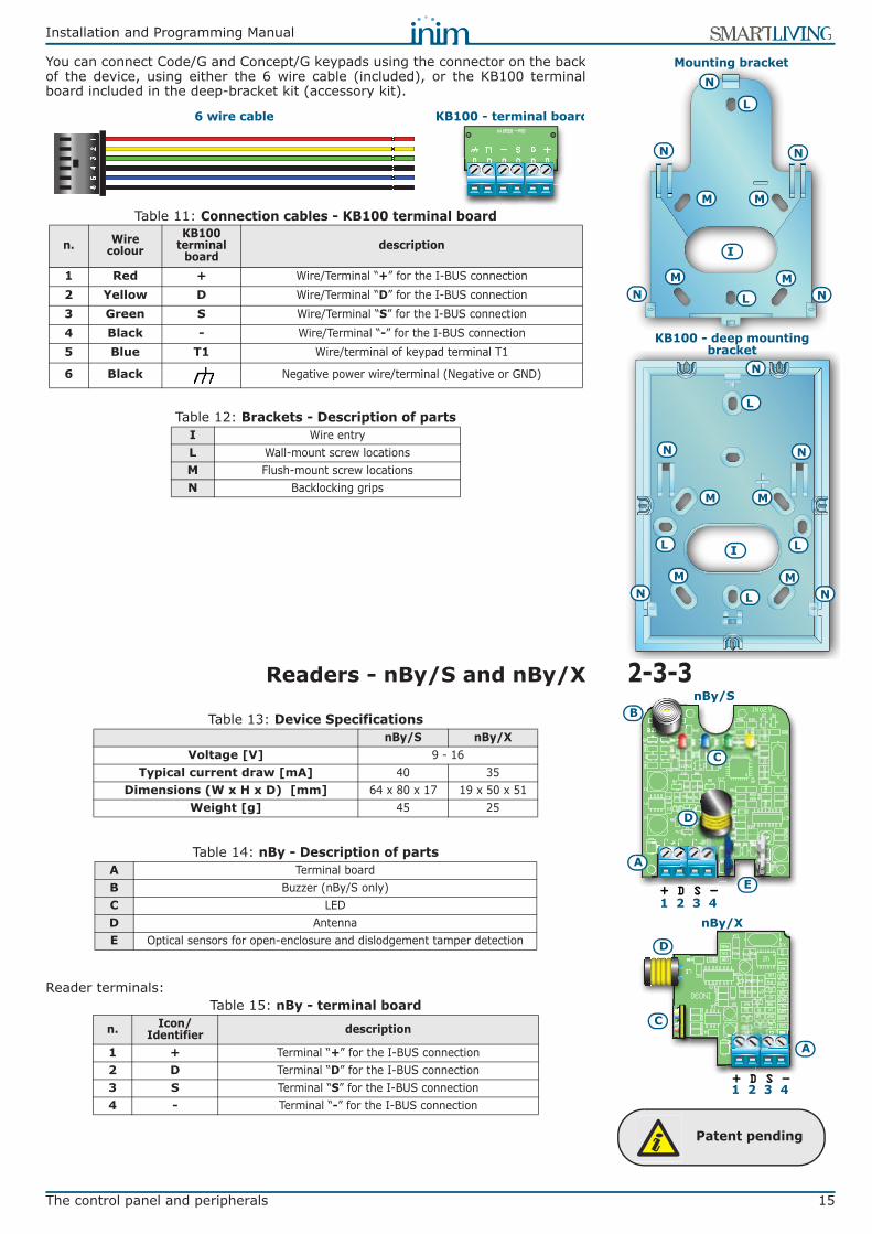
You can connect Code/G and Concept/G keypads using the connector on the backof the device, using either the 6 wire cable (included), or the KB100 terminalboard included in the deep-bracket kit (accessory kit).
2-3-3Readers - nBy/S and nBy/X
Reader terminals:
Table 11: Connection cables - KB100 terminal board
n. Wire colour
KB100 terminal
boarddescription
1 Red + Wire/Terminal “+” for the I-BUS connection2 Yellow D Wire/Terminal “D” for the I-BUS connection3 Green S Wire/Terminal “S” for the I-BUS connection4 Black - Wire/Terminal “-” for the I-BUS connection5 Blue T1 Wire/terminal of keypad terminal T1
6 Black Negative power wire/terminal (Negative or GND)
Table 12: Brackets - Description of partsI Wire entryL Wall-mount screw locationsM Flush-mount screw locationsN Backlocking grips
6 wire cable KB100 - terminal board
I
L
Mounting bracket
L
M M
M M
N
N
N
N N
KB100 - deep mounting bracket
I
L
L
M M
M M
N
N
N
N N
L L
A
B
C
D
E
nBy/S
1 2 3 4nBy/X
D
C
A
1 2 3 4
Table 13: Device SpecificationsnBy/S nBy/X
Voltage [V] 9 - 16Typical current draw [mA] 40 35
Dimensions (W x H x D) [mm] 64 x 80 x 17 19 x 50 x 51Weight [g] 45 25
Table 14: nBy - Description of partsA Terminal boardB Buzzer (nBy/S only)C LEDD AntennaE Optical sensors for open-enclosure and dislodgement tamper detection
Table 15: nBy - terminal board
n. Icon/Identifier description
1 + Terminal “+” for the I-BUS connection2 D Terminal “D” for the I-BUS connection3 S Terminal “S” for the I-BUS connection4 - Terminal “-” for the I-BUS connection
Patent pending

16 The control panel and peripherals
Installation and Programming Manual
2-3-4Flex5 expansion boards
The Flex5 expansion board enclosure is available in two versions.
• Flex5/P comes in the enclosure shown above. This version can be set up tomonitor dislodgement and open-enclosure tamper by inserting a jumper intoconnector [D], as shown.
• Flex5/U comes in an enclosure with on-view terminals and address DIP-Switch, as shown opposite. It is evident that this version offers little protectionto the terminals. The jumper of connector [D] enables/disables the protectionagainst open and dislodgement tamper of the plastic enclosure only.
The packages of both versions of the Flex5 expansion board contain:• Flex5 expansion board in a plastic enclosure• Dislodgement/Open tamper jumper• 10 resistors @3K9W 1/4W• 10 resistors @6K8W 1/4W
Peripheral activity LED signals are as follows:• fast blinking - peripheral operative and enrolled (in configuration)• slow blinking - peripheral operative but not enrolled (not in
configuration)The Flex5 expansion board terminals are as follows:
Terminals T1, T2, T3, T4 and T5 can be configured as:
Table 16: Device SpecificationsFLEX5/P FLEX5/U
Voltage [V] 9 - 16Typical current draw [mA] 30
Max. current across +AUX terminals [mA @13.8V] 300
Dimensions including enclosure (W x H x D) [mm] 125 x 79 x 26 105 x 58 x 18
Weight including enclosure [g] 103 66
Table 17: Flex5 - Description of partsA Terminal boardB BuzzerC DIP-Switch strip for peripheral device addressingD Connector to enable peripheral-tamper detectionE Dislodgement tamper microswitchF Open-tamper microswitchG Peripheral activity LED (where present)
Table 18: Expansion terminal board
n. Icon/Identifier description
1-2-3-4 + D S - I-BUS connection terminals5-6 +AUX 12V ancillary power source terminals
7-9-11-13-15
T1-T2-T3-T4-T5
Screw terminals for expansion terminals: T1, T2, T3, T4 and T5
8-10-12-14-16 Negative power terminals (Negative or GND)
Flex5/P
Flex5/U
A
B C E F
D G

Installation and Programming Manual
The control panel and peripherals 17
• Input (Rollerblind or Shock for terminals T1, T2, T3 and T4 only)• Output• Double zone• Supervised Output
2-3-5Transceiver for Air2-BS100The Air2-BS100 two-way wireless system integrates directly with all models of theINIM intrusion control panel range.Description of the Air2 system devices:• Air2–BS100 wireless transceiver module• Air2–IR100 passive infrared detector• Air2–MC100 magnetic contact/rollerblind/exit• Air2–KF100 4 button remote-control keyfobFor a complete description of all these devices refer to the Air2-BS100Installation Guide.
2-3-6IVY sounder/flasherThe self-powered sounders from the IVY outdoor series are controlledcontinuously by a microprocessor which monitors all the device parameters toensure performance and reliability at all times. For a complete description of all these devices refer to the sounder InstallationGuide.
2-3-7IB100 isolatorsIsolators from the IB100 series peripherals can be connected directly to the I-BUS, in order to increase both its length and performance. Each isolator has 4 input terminals and 4 output terminals for the BUS connectionwith the following functions:• Galvanic Isolation, up to 2500V, for the entire BUS between input and output.• Regeneration of the communication signals.• Detection of anomalies towards the output section and its consequent
isolation.For a complete description of all these devices refer to the respective InstallationGuide.
2-3-8Nexus dialersNexus is the interface between SmartLiving control panels and the GSMcommunication channel managed by the control-panel BUS.The functions made available to control panels equipped with this device are:• voice calls via the Nexus using an installed SmartLogos30M voice board• digital report calls via GSM using CONTACT-ID and ADEMCO 10 bps protocols• SMS messages for each event using either -
•• the description provided by the keypad events log•• the customized description (maximum 50 editable SMS texts)
• the control panel carries out commands sent by the user via SMS message• the control panel carries out commands after recognition of the user's
telephone number (CALLER-ID)• Answerphone
The Nexus package includes:• Nexus expansion board in a plastic enclosure• Remote antenna with 3 meters of cable
Table 19: Device SpecificationsVoltage [V] 9 - 16
Current draw in standby [mA] 90Maximum current draw [mA] 900
Dimensions including enclosure (W x H x D) [mm] 105 x 58 x 18
Weight including enclosure [g] 66
18 The control panel and peripherals
Installation and Programming Manual
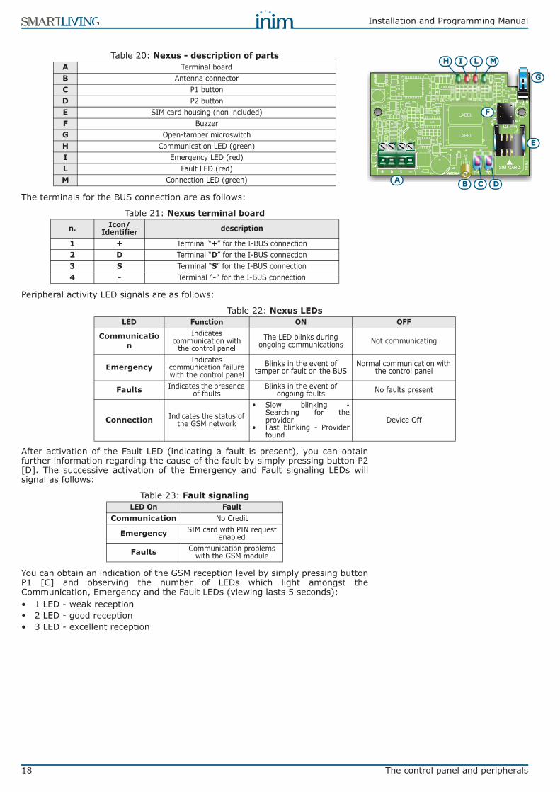
The terminals for the BUS connection are as follows:
Peripheral activity LED signals are as follows:
After activation of the Fault LED (indicating a fault is present), you can obtainfurther information regarding the cause of the fault by simply pressing button P2[D]. The successive activation of the Emergency and Fault signaling LEDs willsignal as follows:
You can obtain an indication of the GSM reception level by simply pressing buttonP1 [C] and observing the number of LEDs which light amongst theCommunication, Emergency and the Fault LEDs (viewing lasts 5 seconds):• 1 LED - weak reception• 2 LED - good reception• 3 LED - excellent reception
Table 20: Nexus - description of partsA Terminal boardB Antenna connectorC P1 buttonD P2 buttonE SIM card housing (non included)F BuzzerG Open-tamper microswitchH Communication LED (green)I Emergency LED (red)L Fault LED (red)M Connection LED (green)
Table 21: Nexus terminal board
n. Icon/Identifier description
1 + Terminal “+” for the I-BUS connection2 D Terminal “D” for the I-BUS connection3 S Terminal “S” for the I-BUS connection4 - Terminal “-” for the I-BUS connection
A B
E
F
G
H L M
C D
I
Table 22: Nexus LEDsLED Function ON OFF
Communication
Indicates communication with
the control panelThe LED blinks during
ongoing communications Not communicating
EmergencyIndicates
communication failure with the control panel
Blinks in the event of tamper or fault on the BUS
Normal communication with the control panel
Faults Indicates the presence of faults
Blinks in the event of ongoing faults No faults present
Connection Indicates the status of the GSM network
• Slow blinking -Searching for theprovider
• Fast blinking - Providerfound
Device Off
Table 23: Fault signalingLED On Fault
Communication No Credit
Emergency SIM card with PIN request enabled
Faults Communication problems with the GSM module

Installation and Programming Manual
Installation 19
Chapter 3
INSTALLATION
3-1Installing the control panel
3-1-1Wall-mountingThe control panel should be located in a hidden place that can be accessed byauthorized building occupants only.
1. Using the backbox (Table 4: Control panels - description of parts, G), markthe anchor screw locations on the wall. Be sure not to drill in the vicinity ofelectrical wiring or plumbing/gas pipes, etc.
2. Insert the screw anchors (recommended size 6mm).3. Pull the wires through the wire entry.4. Using the screws, attach the backbox to the wall.5. Fit the dislodgement-tamper microswitch (provided with SmartLiving
1050L and 10100L, optional for SmartLiving 505, 515 and 1050, refer toAppendix H, Order Codes, TamperNO).5.1. Insert the dislodgement-tamper bracket [A] into its location on the
backbox of the control panel (Table 4: Control panels - description of parts, H).
5.2. Using screw location [B], screw the bracket to the wall.5.3. Connect the wire coming from the dislodgement-tamper microswitch [C] to
the connector [D] on the board (Table 4: Control panels - description of parts, T).
NoteThe sleeving must be flame class rating V-1 or higher.
3-1-2Connecting the Mainspower supply
The control panel must be powered through a separate line coming from theMains box. The line must be protected by a safety-standards compliant circuitbreaker (trip switch).The circuit breaker (trip switch) must be located externally to the apparatus andshould be easily accessible. The distance between contacts must be at least3mm. The manufacturer strongly advises the use of a magnetothermic switchwith C intervention curve and nominal (maximum) current - 16A.The protective earthing system must be compliant with all safety standards andlaws in force.
DANGER!Ensure that the Mains is switched Off during the mains connection phase. Dangerof electric shock.
The 505 and 515 modelsPull the mains (primary power-supply) cable through the cable entry [B], thencomplete the (Mains) connections on the mains terminal board [A]. Whenconnecting the earth wire, follow the indications on the label [C] located near themains terminal board. The transformer (located above the PCB) and switchingpower supply (housed inside the control panel enclosure) provide the powersource to the entire system and supply the charge voltage to the backup battery.
The 1050, 1050L and 10100L modelsPull the cable through the cable entry [E], then connect the mains power to thepower-supply terminal board [D], located on the backplate above themotherboard. When connecting the earth wire, follow the indications on thepower-supply label [F]. The power-supply provides power to the system andsupplies the charge voltage.
A
B
C
D
CE FN
L MAIN FUSE T500mA L250VA
CInput
A
B
C
SmartLiving 505/515
20 Installation
Installation and Programming Manual
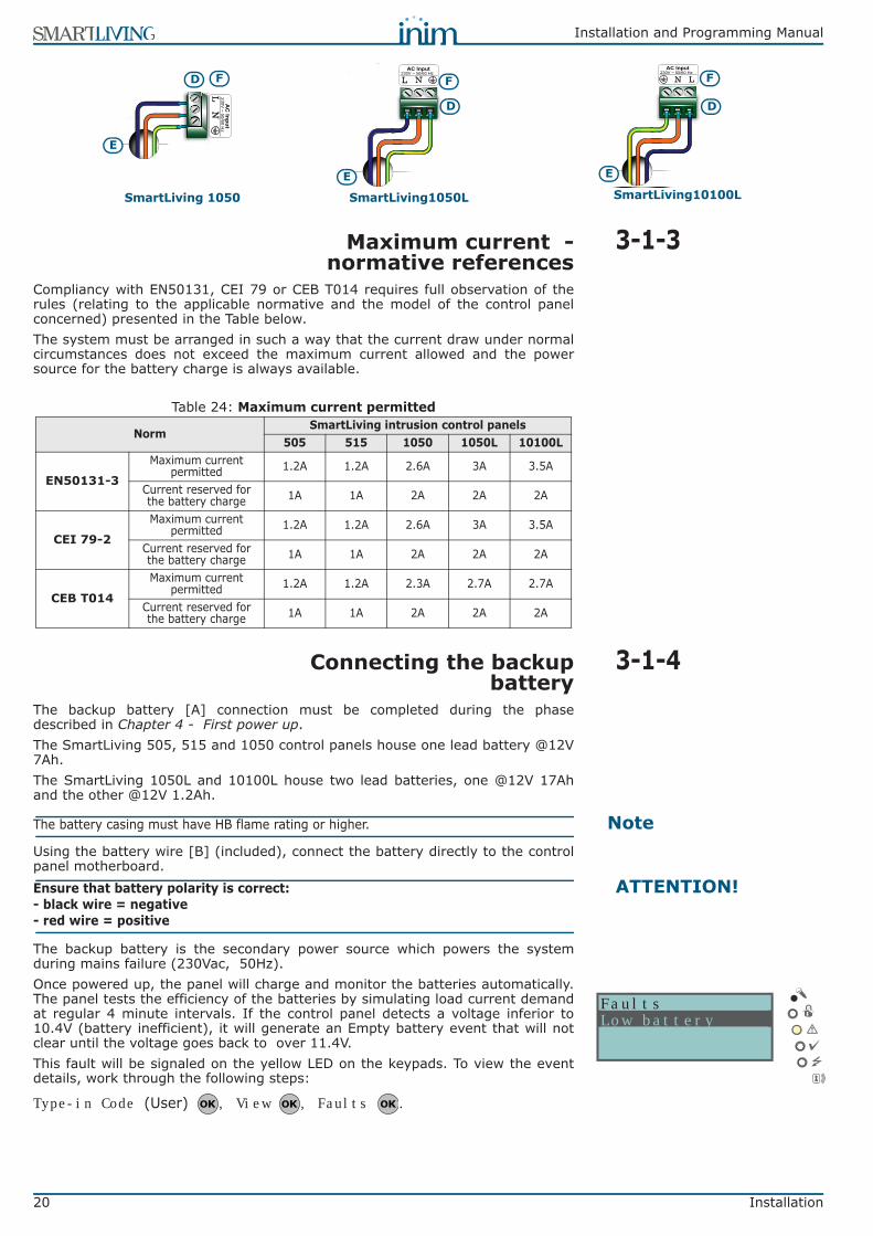
3-1-3Maximum current -normative references
Compliancy with EN50131, CEI 79 or CEB T014 requires full observation of therules (relating to the applicable normative and the model of the control panelconcerned) presented in the Table below.The system must be arranged in such a way that the current draw under normalcircumstances does not exceed the maximum current allowed and the powersource for the battery charge is always available.
3-1-4Connecting the backupbattery
The backup battery [A] connection must be completed during the phasedescribed in Chapter 4 - First power up.The SmartLiving 505, 515 and 1050 control panels house one lead battery @12V7Ah.The SmartLiving 1050L and 10100L house two lead batteries, one @12V 17Ahand the other @12V 1.2Ah.
NoteThe battery casing must have HB flame rating or higher.
Using the battery wire [B] (included), connect the battery directly to the controlpanel motherboard.
ATTENTION!Ensure that battery polarity is correct:- black wire = negative- red wire = positive
The backup battery is the secondary power source which powers the systemduring mains failure (230Vac, 50Hz).Once powered up, the panel will charge and monitor the batteries automatically.The panel tests the efficiency of the batteries by simulating load current demandat regular 4 minute intervals. If the control panel detects a voltage inferior to10.4V (battery inefficient), it will generate an Empty battery event that will notclear until the voltage goes back to over 11.4V.This fault will be signaled on the yellow LED on the keypads. To view the eventdetails, work through the following steps:
Type-in Code (User) , View , Faults .
N L230V ~ 50/60 Hz
AC Input
D
E
F
SmartLiving10100L
ANL230V ~ 50/60 Hz
AC Input
D
E
F
SmartLiving1050L
B
NL 230V
~ 50/60 Hz
AC
I nput
D
E
F
SmartLiving 1050
Table 24: Maximum current permitted
NormSmartLiving intrusion control panels
505 515 1050 1050L 10100L
EN50131-3
Maximum current permitted 1.2A 1.2A 2.6A 3A 3.5A
Current reserved for the battery charge 1A 1A 2A 2A 2A
CEI 79-2
Maximum current permitted 1.2A 1.2A 2.6A 3A 3.5A
Current reserved for the battery charge 1A 1A 2A 2A 2A
CEB T014
Maximum current permitted 1.2A 1.2A 2.3A 2.7A 2.7A
Current reserved for the battery charge 1A 1A 2A 2A 2A
FaultsLow battery
Installation and Programming Manual
Installation 21
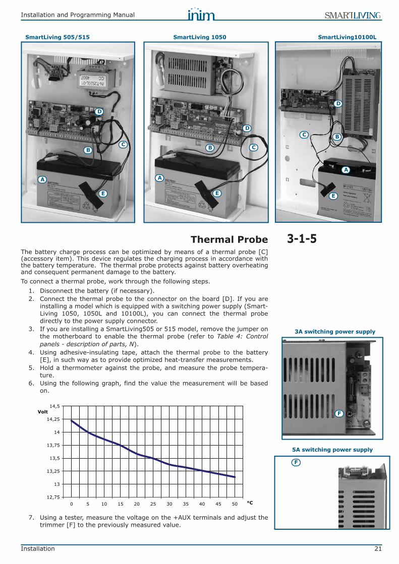
3-1-5Thermal ProbeThe battery charge process can be optimized by means of a thermal probe [C](accessory item). This device regulates the charging process in accordance withthe battery temperature. The thermal probe protects against battery overheatingand consequent permanent damage to the battery.To connect a thermal probe, work through the following steps.
1. Disconnect the battery (if necessary).2. Connect the thermal probe to the connector on the board [D]. If you are
installing a model which is equipped with a switching power supply (Smart-Living 1050, 1050L and 10100L), you can connect the thermal probedirectly to the power supply connector.
3. If you are installing a SmartLiving505 or 515 model, remove the jumper onthe motherboard to enable the thermal probe (refer to Table 4: Controlpanels - description of parts, N).
4. Using adhesive-insulating tape, attach the thermal probe to the battery[E], in such way as to provide optimized heat-transfer measurements.
5. Hold a thermometer against the probe, and measure the probe tempera-ture.
6. Using the following graph, find the value the measurement will be basedon.
7. Using a tester, measure the voltage on the +AUX terminals and adjust thetrimmer [F] to the previously measured value.
A
BC
D
E
A
B C
D
E
SmartLiving 505/515 SmartLiving 1050 SmartLiving10100L
A
BC
D
E
3A switching power supply
F
5A switching power supply
F
12,75
13
13,25
13,5
13,75
14
14,25
14,5
0 5 10 15 20 25 30 35 40 45 50 °C
Volt

22 Installation
Installation and Programming Manual
3-1-6Opening and closing thecontrol panel
If you wish to remove the metal frontplate, work carefully through the followingsteps.
1. Type-in the installer code and press . Access to the installer menu inhib-its the alarm outputs and dialer automatically, therefore, the system will beunable to generate alarms or event calls.
2. Remove the four screws and the metal-frontplate.3. Insert the Service jumper (refer to paragraph 3-1-10 Maintenance status)
and carry out the necessary work.Once your task is complete, work carefully through the following steps.
1. Remove the Service jumper.2. Using the 4 screws, secure the frontplate to the backbox.3. Exit the installer menu.
NoteIf you exit the Installer menu before replacing the panel frontplate, the system panel willnot generate an “Open-panel” event.However, the system will generate an “OpenPanel” event, if the frontplate is not replacedwithin 15 seconds of closing the open-tamper microswitch.
3-1-7Land-line connection (PSTN)Terminals 4 and 5 on the control panel motherboard (Table 5: Control panel -terminal board, 4-5) are for the land-line telephone connection.In order to protect the control panel from lightning, you should use two 150Vrmsvaristors (supplied); they must be connected between the earth terminal 1 andPSTN terminals 4 and 5 on the control panel terminal board.If you are installing the system in a place where the land line (PSTN) service isnot available, or if you wish to increase the level of security of the system, theseterminals also accept a GSM interface (such as Inim's SMARTLINK) whichsimulates the analogue land-line. Inim manufactures two versions of the SMARTLINK GSM Interface: SMARTLINKGand SMARTLINKGP. Both these devices simulate the analogue land line duringline-down conditions (line trouble or wire-cutting) and allow the control panel toswitch incoming/outgoing calls to the GSM network.You can also use the terminals on the SmartLink board to extend the functionsprovided by the SmartLiving system. The following section describes severalmethods which will allow you to provide users with advanced functions.
Arming/Disarming the system over-the-phone using a cost-free call or SMS textIf you connect one of the SmartLiving board terminals, which is configured as a“follow zone”, to an output on the SmartLink board, users will be able to arm ordisarm (“ARM ON” or “DISARM OFF”) the SmartLiving system by sending an SMStext (refer to paragraph 3.12 in the SmartLink programming manual).In a similar way, using a “switch zone”, users will be able to arm or disarm thesystem by calling the control panel (refer to “Caller ID” in paragraph 3.9 in theSmartLink programming manual).
Alarm warning to users via SMS textIf you connect one of the control-panel alarm outputs to an input on theSmartLink board, the system will be able to send users alarm warnings via SMStext (refer to paragraph 3.10 in the SmartLink programming manual). Thesystem can be set up to send an editable SMS text to 10 different contactnumbers.All the functions of the SmartLiving system which use the land line (voice dialer,answerphone, report communications and teleservice) can be managedcompletely over the GSM network by the SmartLink. The SmartLink will also allowyou to carry out teleservice maintenance over the GSM network.
NoteIf there is ADSL line, it will be necessary to connect the control panel downstream of the ADSLfilters, to the line dedicated to telephone equipment (this line is clearly indicated on the filters).
SmartLin
k
Control panel
150Vrms varistors

Installation and Programming Manual
Installation 23
3-1-8Connecting to a PCProgramming from a PC requires the SmartLeague software programme (refer toparagraph 6-3 Programming via the SmartLeague programme) and an RS232serial cable.Insert the RS232 serial link (accessory item) into the connector [A], as shown inthe figure opposite.If you wish to purchase an RS232 serial link, refer to the codes in Appendix H, OrderCodes. If your PC is not equipped with an RS232 port, but has a USB instead, you canuse INIM's Approved RS232-USB adaptor (accessory item).
3-1-9Connecting the SmartLogos30Mvoice board (accessory item)
The SmartLogos30M voice board provides the SmartLiving system with an arrayof useful voice functions.For proper installation of the board, work carefully through the following steps.
1. Disconnect all power sources to the control panel (mains and lead batter-ies).
2. Connect the board to the respective connector [B].3. Power up the system from the mains and reconnect the lead batteries.
SmartLiving endDB9F connector
PC endDB9F connector
2 33 24 45 56 67 78 8
SmartLiving endDB9F connector
PC endDB25F connector
2 2
3 3
4 20
5 7
6 6
7 48 5
B
A9
1
1
9
9
1
1
25

24 Installation
Installation and Programming Manual
3-1-10Maintenance statusThere are two distinct positions for the Service jumper (Table 4: Control panels -description of parts, Q):
1. “RUN” (control panel operating normally)2. “SERV” (control panel ready for maintenance work)
The keypads indicate maintenance status (jumper in “SERV” position) by showingthe “Maintenance” message on the first line on the display next to the keypadaddress. The address of the built-in reader (if enabled) of JOY/MAX keypads willalso be shown.Under these circumstances, the control panel:• Forces the relay output on the motherboard (Table 5: Control panel - terminal
board, 10-11-12) to standby status.• Does not activate the outputs (and will force to standby any active outputs)
triggered by:•• alarm or zone/partition tamper•• peripheral tamper•• open/dislodged panel tamper
• It allows initialization of the keypad address programming phase.• It allows initialization of the reader address programming phase.• It initializes automatically the auto-enrolment of the peripherals connected to
the BUS at 10 seconds intervals. It allows assignment of the addresses to theperipherals connected to the BUS and, at 10 second intervals, enrolls theperipherals it finds.
• The control panel will not reset the BUS in an attempt to retrieve peripheralsin the event of peripheral loss.
• It will continue to operate as normal, except under the aforesaidcircumstances.
3-2Connecting peripherals
3-2-1The I-BUS line wiringThe SmartLiving peripherals (keypads, readers, expansions, sounderflashers,transceivers, isolators and GSM communicator) must be connected to the controlpanel via the I-BUS.The wiring diagram opposite provides an example of a 4-wire connection (usingshielded cable) between a control panel and its peripherals.The cable specifications depend on the length of the BUS (from the panelterminals to the most distant point), Baud rate and the load current draw.
The maximum wire length of the I-BUS depends on the deployment of theperipherals connected to the line and their specific current draw (in particular thekeypads and expansion boards). The power to peripherals and detectors can besupplied by external power stations or by the line itself.Furthermore, the speed of the communication BUS (Baud rate) can be modifiedby means of the SmartLeague programming software. If the BUS is not used topower the peripherals and their loads, the maximum wire length is 300 meters @250kbs, regardless of the number of peripherals involved.An intermediate speed (125kbs) can support a single section of 700 meters.
Position 1 Position 2
Mainten K03 P05DASIDASI--
Keypad address
Reader address
Table 25: Recommended cableCable
AF CEI 20-22 II n. wires Section (mm2)
I-BUS terminal
4 wire cable + shield
2 0.5 + -2 0.22 D S
6 wire cable + shield
2 0.5 + -2 0.22 D S2 0.22 available
6 wire cable + shield
2 0.75 + -2 0.22 D S2 0.22 available
Shield + D S -

Installation and Programming Manual
Installation 25
ATTENTION!The shield must be connected to one of the terminals (Negative or GND) atthe control panel end only, and must run along the BUS without being connectedto negative or GND at any other point.
If you wish to increase the length and performance of the BUS, you can connectIB100 isolators .If the speed of the communication BUS (Baud rate) is low (38.4 or 125 kbps),you can apply a maximum of 5 isolators in a cascade connection.If the speed of the communication BUS (Baud rate) is high (250 or 2 kbps), youcan apply a maximum of 2 isolators in a cascade connection.You can connect up to 15 isolators in all.
ATTENTION!It is extremely important to evaluate correctly the number of isolators connectedin cascade to the BUS.
The following example will help you achieve a correct evaluation:
3-2-2Installing JOY keypads1. Remove the keypad from its package.2. Detach the down-flip and cover from the backplate.3. Remove the board from the backplate. Be careful not to damage the dis-
lodgement-tamper spring ([A]) during this operation.4. Mark the chosen anchor-screw locations [B] on the wall. Use at least 2 of
the 7 locations available. Drill the anchor-screw holes (ensure that you donot drill in the vicinity of electrical wiring or plumbing). Pull the BUS andterminal connection wires through the wire entry [C] and attach the back-plate securely to the wall.
5. Using the screw, fasten the dislodgement-tamper bracket into its screwlocation [D].
6. For JOY/MAX only: Plug the speaker connector [E] into the keypad circuit,ensure that polarity is correct (black wire to the right [F] and red wire tothe left [G]). Be careful not to damage the connector during this operation.If it becomes necessary to separate the connector from the speaker, use asmall screwdriver or similar tool to disengage it. DO NOT pull the connectorout by the wires.
7. Place the circuit on the two lower supports [H] and, after aligning it with theother supports [I], push the back-locking grip [J] slightly outwards until itclicks closed. Be careful not to damage the dislodgement-tamper spring [A].
8. Replace the cover and down-flip. If necessary, secure the two screws intotheir screw locations on the bottom part of the cover.
Control panelIB100
IB100
IB100 IB100
BUS sections:1 isolator in cascade
connection
IB100
BUS sections:2 isolators in
cascade connection
BUS sections:3 isolators in
cascade connection
C
E
A
D
B
BB
E
GF
I
J
E
H

26 Installation
Installation and Programming Manual
3-2-3Installing nCode/G andConcept/G keypads
1. Connecting the device to the system2. Pull the connection wires through the wire entry [A].3. Connect the cables to the connector on the keypad backplate [B]. If you
are using the connector provided with the KB100 kit [C], connect the wiresto the terminals, in accordance with the instructions described in paragraph2-3-2 nCode/G and Concept/G Keypads, then insert the connector into theguide [D] until it locks into place.
4. Using at least 2 screws, mount the bracket to the wall.5. Using the back-locking grips, attach the keypad to the bracket (as shown in
figure [E].6. Fasten the screw [F] (included) into the screw location [G], to secure the
keypad properly to the bracket.
3-2-4Installing nBy/S readersThe wall-mount nBy/S reader is suitable for indoor and outdoor installation.Insert the two anchor screws [A] (included) into the two screw locations [B] onthe plastic backplate.
ATTENTION!In order to avoid the risk of piercing the silicone seal [C], and thus jeopardizingthe waterproofing of the enclosure, insert the screws before fitting the seal.
3-2-5Installing nBy/X readersThe Universal flush-mount nBy/X (Patent Pending) has been especiallydesigned to integrate with all brands of cover plates [A]. Drill two holes [B] forthe light guide [C].Use the adhesive drill-pattern (see opposite) to mark the drilling locationsaccurately.
B
C
D
A
E
G
F
C
A
B
A
B
Installation and Programming Manual
Installation 27
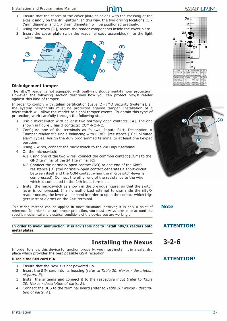
1. Ensure that the centre of the cover plate coincides with the crossing of theaxes x and y on the drill-pattern. In this way, the two drilling locations (1 x7mm diameter and 1 x 8mm diameter) will be positioned precisely.
2. Using the screw [D], secure the reader components inside the cover plate. 3. Insert the cover plate (with the reader already assembled) into the light
switch box.
Dislodgement tamperThe nBy/X reader is not equipped with built-in dislodgement-tamper protection.However, the following section describes how you can protect nBy/X readeragainst this kind of tamper.In order to comply with Italian certification (Level 2 - IMQ Security Systems), allthe system peripherals must be protected against tamper. Installation of amicroswitch will allow the reader to signal tamper events. To obtain this type ofprotection, work carefully through the following steps.
1. Use a microswitch with at least two normally-open contacts [A]. The oneshown in figure 3 has 3 contacts: COM-NO-NC.
2. Configure one of the terminals as follows: Input; 24H; Description =“Tamper reader x”; single balancing with 6K8W [resistance [B]; unlimitedalarm cycles. Assign the duly programmed terminal to at least one keypadpartition.
3. Using 2 wires, connect the microswitch to the 24H input terminal.4. On the microswitch:
4.1. using one of the two wires, connect the common contact (COM) to the GND terminal of the 24H terminal [C].
4.2. Connect the normally-open contact (NO) to one end of the 6k8W resistance [D] (the normally-open contact generates a short-circuit between itself and the COM contact when the microswitch-lever is compressed). Connect the other end of the resistance to the wire which is connected to the 24h input terminal.
5. Install the microswitch as shown in the previous figure, so that the switchlever is compressed. If an unauthorized attempt to dismantle the nBy/Xreader occurs, the lever will expand in order to open the contact which trig-gers instant alarms on the 24H terminal.
NoteThis wiring method can be applied in most situations, however, it is only a point ofreference. In order to ensure proper protection, you must always take in to account thespecific mechanical and electrical conditions of the device you are working on.
ATTENTION!In order to avoid malfunction, it is advisable not to install nBy/X readers ontometal plates.
3-2-6Installing the NexusIn order to allow this device to function properly, you must install it in a safe, dryplace which provides the best possible GSM reception.
ATTENTION!Disable the SIM card PIN.
1. Ensure that the Nexus is not powered-up.2. Insert the SIM card into its housing (refer to Table 20: Nexus - description
of parts, E).3. Install the antenna and connect it to the respective input (refer to Table
20: Nexus - description of parts, B).4. Connect the BUS to the terminal board (refer to Table 20: Nexus - descrip-
tion of parts, A).
CA
D
B
D AC
B
28 Installation
Installation and Programming Manual
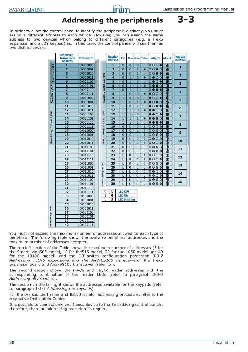
3-3Addressing the peripheralsIn order to allow the control panel to identify the peripherals distinctly, you mustassign a different address to each device. However, you can assign the sameaddress to two devices which belong to different categories (e.g. a Flex5expansion and a JOY keypad) as, in this case, the control panels will see them astwo distinct devices.
You must not exceed the maximum number of addresses allowed for each type ofperipheral. The following table shows the available peripheral addresses and themaximum number of addresses accepted.The top left section of the Table shows the maximum number of addresses (5 forthe SmartLiving505 model, 10 for the515 model, 20 for the 1050 model and 40for the 10100 model) and the DIP-switch configuration paragraph 3-3-2Addressing FLEX5 expansions and the Air2-BS100 transceiverof the Flex5expansion board and Air2-BS100 transceiver (refer to ). The second section shows the nBy/S and nBy/X reader addresses with thecorresponding combination of the reader LEDs (refer to paragraph 3-3-3Addressing nBy readers).The section on the far right shows the addresses available for the keypads (referto paragraph 3-3-1 Addressing the keypads).For the Ivy sounderflasher and IB100 isolator addressing procedure, refer to therespective Installation Guides.It is possible to connect only one Nexus device to the SmartLiving control panels,therefore, there no addressing procedure is required.
Smar
tLiv
ing5
15Sm
artL
ivin
g105
0 an
d 10
50L
Smar
tLiv
ing1
0100
LSm
artL
ivin
g505
DIP-switch
1 000000002 000000013 000000104 000000115 000001006 000001017 000001108 000001119 00001000
10 0000100111 0000101012 0000101113 0000110014 0000110115 0000111016 0000111117 0001000018 0001000119 0001001020 0001001121 0001010022 0001010123 0001011024 0001011125 0001100026 0001100127 0001101028 0001101129 0001110030 0001110131 0001111032 0001111133 0010000034 0010000135 0010001036 0010001137 0010010038 0010010139 0010011040 00100111
nBy/S nBy/X
1 0 0 0 1 12 0 0 1 03 0 0 1 1 24 0 1 0 05 0 1 0 1 36 0 1 1 07 0 1 1 1 48 1 0 0 09 1 0 0 1 510 1 0 1 0
11 1 0 1 1 612 1 1 0 013 1 1 0 1 714 1 1 1 015 1 1 1 1 816 0 0 0 L17 0 0 L 0 918 0 0 L L19 0 L 0 0 1020 0 L 0 L21 0 L L 0 1122 0 L L L23 L 0 0 0 1224 L 0 0 L25 L 0 L 0 1326 L 0 L L27 L L 0 0 1428 L L 0 L29 L L L 0 1530 L L L L
Sm
artL
ivin
g5
05
an
d 5
15
Sm
artL
ivin
g1
05
0 a
nd
10
50
LS
mar
tLiv
ing
10
10
0L
01L
LED OFFLED ONLED blinking
Expansion -Transceiver
addressReaderaddress Red Blue Green Yellow Keypad
address

Installation and Programming Manual
Installation 29
3-3-1Addressing the keypadsWork carefully through the following steps.
1. Put the control panel in “Maintenance” mode by inserting the respectivejumper (Table 4: Control panels - description of parts, Q).
2. Using the keypad you wish to address, press and release keys and
simultaneously; set the address then press (if the keypadfirmware version is 1.02 or higher, go to point 5).
3. For JOY/MAX only: enable or disable the reader press keys or .4. For JOY/MAX only: if the reader is enabled, assign the address and press
.5. If the keypad firmware version is 1.02 or higher, enable or disable the dis-
lodgement tamper protection by pressing or .6. If the keypad firmware version is 1.08 or higher, enable or disable the dis-
lodgement tamper protection by pressing or .
NoteFor security reasons, if the address is not assigned within 30 minutes of accessing“Maintenance” mode (SERV jumper inserted), the keypad will exit the programming phaseautomatically. If this occurs and you wish to restart the programming phase, remove and re-insert thejumper.The same procedure is necessary when you re-address the keypad.
3-3-2Addressing FLEX5 expansions and theAir2-BS100 transceiver
Using a small screwdriver or similar tool, set the expansion board address on the8-segment DIP-Switch strip (Table 17: Flex5 - Description of parts, C). Eachsegment can be set at “1” (On) or “0” (Off).The figure shows some examples.
3-3-3Addressing nBy readersTo assign addresses to the system readers, work carefully through the followingsteps.
1. Put the control panel in “Maintenance” mode by inserting the respectivejumper (Table 4: Control panels - description of parts, Q).
2. Start the “Address Programming” phase using the software or from a key-pad:
Type-in Code (Installer PIN) , PROGRAMMING Readers , Prog. address .
3. Each reader indicates its own address on its LEDs (refer to the Table inparagraph 3-3 Addressing the peripherals).
4. Hold a valid key in the vicinity of the reader. The reader will run through aseries of available reader-addresses (an address every 2 seconds). Removethe key when the LEDs indicate the desired address.
5. The reader will hold the addressing phase for a further 10 seconds, in order toallow you to change the address if necessary.
6. The reader will assign the selected address when the 10 second periodexpires.
keypad address
_1
Min. 01
Max. 30
ON
1 2 3 4 5 6 7 8
Position 1
Position 2
ON
1 2 3 4 5 6 7 8
ON
1 2 3 4 5 6 7 8
ON
1 2 3 4 5 6 7 8
Expansion n. 1
Expansion n.29
Expansion n.40
This procedure does not apply to the built-in
readers of JOY/MAX keypads.

30 Installation
Installation and Programming Manual
7. If you wish to assign an address to another reader, hold a valid key in thevicinity of the reader and work through points 4 to 6.
8. End the reader-address programming phase (exit “Prog. address” via key-pad, or click on “Stop reader address setup”, if you are using the Smart-League software).
3-4Auto-enrolling peripheralsThe peripherals connected to the BUS are enrolled automatically in the followingsituations: • on first startup (refer to Chapter 4 - First power up)• if the SERV jumper is inserted (refer to paragraph 3-1-10 Maintenance status)• via the Installer menu (refer to paragraph 6-23 Default settings) >
Type in Code (Installer) , PROGRAMMING Default settings , Auto Periph .
3-5Wiring and balancingalarm detectors
The wiring and respective balancing method depend on the type of detector youare installing, and the level of protection you wish to achieve. The detectors canbe powered through:• terminals [+AUX/12V] and [-/GND] on the control panel• terminals [+AUX/12V] and [-/GND] on FLEX5 expansions• terminal [+/12V] and terminals [-/GND] on keypads• from any 12V ancillary source on condition that its GND reference is in
common with that of the control panel.The resistors used for balancing are:
•• 3K9W 1/4W•• 6K8W 1/4W
The following Table indicates the protection level of each detector type and thebalancing options provided by the control panel:
3-5-1N.C./N.O. BalancingFor N.C. (normally closed) and N.O. balancing (normally open), it ispossible to detect two distinct zone conditions:• standby• alarmFor each of these, the control panel reads different resistance values onthe terminal, expressed below in Ohm.
If you wish the detector to signal tamper events, connect the detector“Tamper” terminal to a “24h” zone on the control panel.
Table 26: Protection level
BALANCING N.O. N.C. Single Double Double zone
Double zone
with EOLInfrared or
Double technology
very low low medium (*) high medium high
Magnetic contact very low low medium medium high
3K9Ω 1/4W
6K8Ω 1/4W
RedWhite
OrangeGold
RedGreyBlue
Gold
(*) Single balancing provides the same level of protection as
Double balancing, when the tamper contact of the detector is connected to a balanced zone on
the control panel.
WW N.C. N.O.> 2 x 3900 + 6800 alarm standby> 2 x 3900 + 6800 alarm standby
3900 + 6800 alarm alarm2 x 3900 alarm alarm
3900 standby alarm0 standby alarm A
larm
+12V GNDTamper

Installation and Programming Manual
Installation 31
3-5-2Single balancingSingle zones can discriminate 3 conditions on the entire terminal:• standby• alarm• tamper (short-circuit)For each of these, the control panel reads different resistance values onthe terminal, expressed below in Ohm.
If you wish the detector to signal tamper events, connect the detector“Tamper” terminal to a “24h” zone on the control panel.
3-5-3Double balancingDouble balancing discriminates 4 distinct conditions on the zone terminal:• standby• alarm• tamper (short-circuit)• tamper (wire cutting)For each of these, the control panel reads different resistance values onthe terminal, expressed below in Ohm.
3-5-4Double-Zone balancingDouble zones without EOL resistor can discriminate 5 conditions on theentire terminal:• standby on both zones• alarm on zone 1 and standby on zone 2• alarm on zone 2 and standby on zone 1• alarm on both zones• tamper (wire cutting)For each of these, the control panel reads different resistance values onthe terminal, expressed below in Ohm.
W Zone> 6800 alarm6800 standby
0 tamper
Alarm
+12V GNDTamper
6K8WW 1/4W
WW Zone> 6800 tamper (wire cutting)6800 alarm
6800 / 2 standby0 tamper (short-circuit) A
larm
+12V GNDTamper
6K8WW 1/4W
W Zone 1 Zone 2 (double)
> 3900 + 6800 tamper3900 + 6800 alarm alarm
6800 standby alarm3900 alarm standby
0 standby standby
Alarm
+12V GNDTamper
Alarm
+12V GNDTamper
3K9WW 1/4W
6K8W 1/4W
Zone 1
Zone 2

32 Installation
Installation and Programming Manual
3-5-5Double Zone balancing with EOLDouble zones with EOL resistors can discriminate 6 conditions on theentire terminal:• standby on both zones• alarm on zone 1 and standby on zone 2• alarm on zone 2 and standby on zone 1• alarm on both zones• tamper (wire cutting)• tamper (short-circuit)For each of these, the control panel reads different resistance values onthe terminal, expressed below in Ohm.
3-6Wiring and balancingrollerblind/shock sensors
It is possible to choose between two types of balancing for Rollerblind and Shocksensors:• Normally Closed (N.C.)• Single balancing (NC with EOL)The following table compares the protection level of rollerblind/shock sensorsusing the two balancing options provided by the control panel.
If the rollerblind or shock sensor is connected to a terminal of a wireless device,the connection cable must be less than 2 meters long.The rollerblind sensor must generate pulses with a length of between 500msecand 10msec.
3-6-1Normally Closed (N.C.)In this case, the alarm condition is revealed exclusively by the number of pulses(pulse count) the control panel detects on the terminal.If this balancing method is applied, the control panel will be unable to detecttamper, wire-cutting or short-circuit.The discriminated conditions are:• standby• alarmThe alarm condition is triggered by the number of pulses and sensitivity, inaccordance with the programmed parameters (refer to paragraph 6-6 Zones -Detector type).
W Zone 1 Zone 2 (double)
> 2 x 3900 + 6800 tamper (wire cutting)> 2 x 3900 + 6800 alarm alarm
3900 + 6800 standby alarm2 x 3900 alarm standby
3900 standby standby0 tamper (short-circuit)
Alarm
+12V GNDTamper
Alarm
+12V GNDTamper
3K9WW 1/4W
6K8W 1/4W
Zone 1
Zone 2
Table 27: Protection level
BALANCING N.C. Single balancing(N.C. with EOL)
Rollerblind or Shock very low high

Installation and Programming Manual
Installation 33
3-6-2Single balancing(N.C. with EOL)
In this case, the discriminated conditions are:• standby• alarm• tamper (wire cutting)• tamper (short-circuit)For each of these, the control panel reads different resistance values on theterminal, expressed below in Ohm.
The alarm condition is triggered by the number of pulses and sensitivity, inaccordance with the programmed parameters (refer to paragraph 6-6 Zones -Rollerblind/Shock).
3-7Connecting wirelessdetectors
For the connection and deployment of wireless detectors (Air2-IR100 and Air2-MC100), refer to the Air2-BS100 Installation Guide.For the connection and balancing of detectors connected to terminals “T1” and“T2” of the Air2-MC100 device, refer to paragraphs 3-5-1, 3-5-2, 3-5-3, 3-6-1and 3-6-2.It is necessary for the “GND” terminal of the Air2-MC100 device to be connectedto GND (Negative) of the power source of the detector connected to terminals“T1” or “T2”.
3-8Learn Zone BalancingOnce you have completed the wiring and configured the balancing of all the zones,you can instruct the control panel to save all the related parameters automatically, byactivating the Learn zone bal. option (refer to paragraph 6-23 Default settings, Learnzone bal.).
3-9Connecting the outputsIt is possible to set up the outputs to activate in response to the events thecontrol panel manages.For the connection of the outputs to terminals “T1” and “T2” of the Air2-MC100device, refer to the Air2-BS100 Installation Guide.
3-9-1Connecting the soundersIn the event of intrusion alarm, the control panel activates the output/s which areconnected to the audible/visual signaling devices. The relay output on the controlpanel motherboard is the alarm output which is most commonly used to drive aself-powered sounder. The following wiring diagram shows the connection of a self-powered sounder (IVYmanufactured by INIM) and an indoor sounder.
3K9WW1/4W
WW Zone > 3900 / 2 tamper (wire cutting)
3900 / 2 standby0 tamper (short-circuit)
CR
123A
3V-
CR
123A
3V----
Alarm
+12V GNDT
Switching
Detector
Air2-MC100
PatentPatent pending
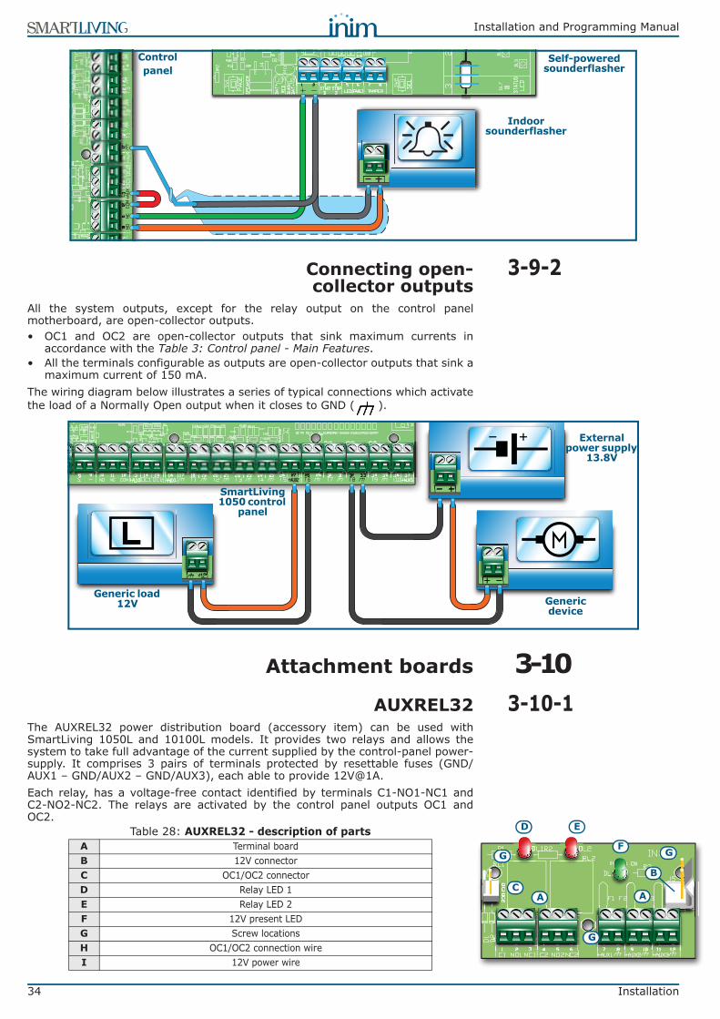
34 Installation
Installation and Programming Manual
3-9-2Connecting open-collector outputs
All the system outputs, except for the relay output on the control panelmotherboard, are open-collector outputs.• OC1 and OC2 are open-collector outputs that sink maximum currents in
accordance with the Table 3: Control panel - Main Features.• All the terminals configurable as outputs are open-collector outputs that sink a
maximum current of 150 mA.The wiring diagram below illustrates a series of typical connections which activatethe load of a Normally Open output when it closes to GND ( ).
3-10Attachment boards
3-10-1AUXREL32The AUXREL32 power distribution board (accessory item) can be used withSmartLiving 1050L and 10100L models. It provides two relays and allows thesystem to take full advantage of the current supplied by the control-panel power-supply. It comprises 3 pairs of terminals protected by resettable fuses (GND/AUX1 – GND/AUX2 – GND/AUX3), each able to provide [email protected] relay, has a voltage-free contact identified by terminals C1-NO1-NC1 andC2-NO2-NC2. The relays are activated by the control panel outputs OC1 andOC2.
Controlpanel
Self-powered sounderflasher
Indoor sounderflasher
SmartLiving1050 control
panel
Generic load 12V
External power supply
13.8V
Generic device
Table 28: AUXREL32 - description of partsA Terminal boardB 12V connector C OC1/OC2 connector D Relay LED 1E Relay LED 2F 12V present LEDG Screw locationsH OC1/OC2 connection wireI 12V power wire
AC
E
F
D
G
A
G
G
B

Installation and Programming Manual
Installation 35
The activation of each relay is signaled by the on-board LED ([D] for relay 1 and[E] for relay 2).If you intend installing this board, work carefully through the following steps.
1. Disconnect all sources of power to the control panel (Mains 230V a.c andbattery power).
2. Insert the plastic supports into their respective locations (Table 4: Controlpanels - description of parts, Z) on the back of the metal enclosure.
3. Position the board holes [G] on the supports and push the board towardsthe back of the enclosure until it locks into position.
4. Insert the cable [H] into the connector [C].5. Connect the two free wires of the cable [H] to terminals 14 (OC1) and 15
(OC2) on the control panel motherboard. Ensure that OC1 and OC2 on thecontrol panel are appropriately connected to the connector [C].
6. Connect the cable [I] to the connector [B] and to the 2 free pins [J] of theconnector on the switching power-supply, as shown in the figure.
3-10-2SmartLink/GWBThe metal enclosures of SmartLiving 1050L and 10100L control panels providehousing for SmartLink/GWB accessory boards and the respective [email protected] batteries.For the technical features and functions provided by these boards, refer toparagraph 3-1-7 Land-line connection (PSTN).The SmartLink/GWB kit includes:• SmartLink/G board• GSM antenna with 3 meter cable• Screws and star washers• Plastic supports for box mounting• 10 resistors @ 15KW 1/4WThe picture opposite shows the SmartLink mounted inside its enclosure. If youintend installing this board, work carefully through the following steps.
1. Disconnect all sources of power to the control panel (Mains 230V a.c andbattery power).
2. Insert the plastic supports into their respective locations (Table 4: Controlpanels - description of parts, C1) on the back of the metal enclosure.
3. Position the board holes [A] on the supports and push the board towards the backof the enclosure until it locks into position.
4. Secure the screw and star washer in place [B].5. Connect terminal “1” ([C] “PWR+”) to a “+AUX” terminal on the control
panel motherboard, and terminal “2” ([C] “PWR-”) to a “ ” terminal onthe control panel motherboard.
6. Power up the control panel (reconnect Mains 230V a.c and battery power).7. Locate the battery properly into its housing (Table 4: Control panels - description
of parts, E1) and connect the wires [D] (red-positive, black-negative).
H I
J
I
H
B
C
A
B
C
A
A
D
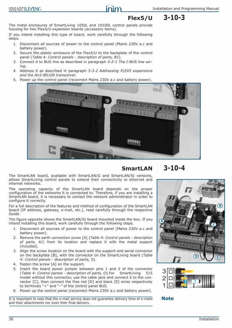
36 Installation
Installation and Programming Manual
3-10-3Flex5/UThe metal enclosures of SmartLiving 1050L and 10100L control panels providehousing for two Flex5/U expansion boards (accessory items).If you intend installing this type of board, work carefully through the followingsteps.
1. Disconnect all sources of power to the control panel (Mains 230V a.c andbattery power).
2. Secure the plastic enclosure of the Flex5/U to the backplate of the controlpanel (Table 4: Control panels - description of parts, B1).
3. Connect it to BUS line as described in paragraph 3-2-1 The I-BUS line wir-ing.
4. Address it as described in paragraph 3-3-2 Addressing FLEX5 expansionsand the Air2-BS100 transceiver.
5. Power up the control panel (reconnect Mains 230V a.c and battery power).
3-10-4SmartLANThe SmartLAN board, available with SmartLAN/G and SmartLAN/SI versions,allows SmartLiving control panels to extend their connectivity to ethernet andinternet networks.The operating capacity of the SmartLAN board depends on the properconfiguration of the networks it is connected to. Therefore, if you are installing aSmartLAN board, it is necessary to contact the network administrator in order toconfigure it correctly.For a full description of the features and method of configuration of the SmartLANboard (IP address, gateway, e-mail, etc.), read carefully through the respectiveGuide.The figure opposite shows the SmartLAN/SI board mounted inside the box. If youintend installing this board, work carefully through the following steps.
1. Disconnect all sources of power to the control panel (Mains 230V a.c andbattery power).
2. Remove the earth connection screw [A] (Table 4: Control panels - descriptionof parts, A1) from its location and replace it with the metal support(included).
3. Align the screw location on the board with the support and serial connectoron the backplate [B], with the connector on the SmartLiving board (Table4: Control panels - description of parts, S).
4. Fasten the screw [A] on the support.5. Insert the board power jumper between pins 1 and 2 of the connector
(Table 4: Control panels - description of parts, O).For SmartLiving 515model without this connector, use the cable jack and connect it to the con-nector [C], then connect the free red [D] and black [E] wires respectivelyto terminals “+” and “-” of the control panel BUS.
6. Power up the control panel (reconnect Mains 230V a.c and battery power).
NoteIt is important to note that the e-mail service does not guarantee delivery time of e-mailsand their attachments nor even their final delivery.
A
B
C
D E
321

Installation and Programming Manual
First power up 37
Chapter 4
FIRST POWER UP
On first power up, the control panel initializes the parameters at default (factorysettings).The control panel also enrolls all the peripherals it finds on the I-BUSautomatically (automatic addressing phase). The default address of allexpansions, keypads and readers is address 1, therefore, if the system isequipped with more than one of each type of device, the automatic enrollingoperation will be erroneous. In order to allow the system to perform an accurateauto-enrolling operation on "First power-up", work carefully through the followingsteps.
NoteThe default address of all peripherals (keypads, readers and expansions) is set at address1.
ATTENTION!When wiring the system, be careful not to allow any form of power (mains 230Vor battery) to reach the control panel or its peripherals.
1. Attach the control panel to the wall.2. Complete the wiring of the peripherals to the BUS.3. Connect the BUS wires to the control panel.4. Complete the wiring and balancing of the system detectors.5. Connect the detectors to the terminals.6. Connect the outputs to the control panel and peripheral terminals.7. Connect the control panel to the telephone line.8. Connect the SmartLogos30M board to the appropriate connector on the
control panel motherboard.9. Insert the Service jumper in the “SERV” position.10. Connect the primary power source (230V a.c.).11. Connect the backup battery. The first line of the display of each keypad in
the system will show the 'Maintenance' message and the keypad address atdefault. On first power up (first startup), all the keypads will show "K01"(refer to paragraph 3-1-10 Maintenance status).
NoteIf several keypads are connected to the I-BUS, their displays may be blank. If this occurs,disregard this aspect and go directly to the next step.
12. Address the peripherals (refer to paragraph 3-3 Addressing the peripher-als). At least one keypad must be assigned to address 1. Using keypad 1,initialize the addressing phase for nBy/S and nBy/X readers (refer to para-graph 3-3-3 Addressing nBy readers).
13. If you wish to instruct the system to learn the "balancing values" of all thezones, initialize the procedure via the installer menu (refer to paragraph 6-23 Default settings,Learn zone bal.).
14. Remove the jumper from the “SERV” position and place it in the “RUN”position.
15. If necessary, specify the expansion terminals simulated by the Air2-BS100transceiver (refer to paragraph 6-5 Terminals) as “Wireless” terminals.
16. If you decide to set up the voice and digital dialer functions and edit thecontact numbers (refer to paragraph 6-8 Telephone).

38 Installation project via SmartLeague software
Installation and Programming Manual
Chapter 5
INSTALLATION PROJECT VIASMARTLEAGUE SOFTWARE
The especially designed SmartLiving system can be programmed from a keypador via PC. All programming functions can be accessed through the softwareprogramme. You will need:• A computer (to be connected to the control panel)• The SmartLeague software programme
5-1The SmartLeague softwareprogramme
The SmartLeague software programme allows the installer to prepare themajority of the parameters/settings without actually being connected to thecontrol panel. However, connection is required during the upload and download operations. Thetype of connection depends on the method used for upload/download operationsto and from the control panel:• RS232 serial port of the PC• LAN (combined with the use of a SmartLAN/SI or SmartLAN/G board)• ModemThe programming parameters of an installation constitute the “solution”. Thesolution can be saved to the memory of the SmartLeague software programme,either for future use or as a “model” for other installations.The homepage of the SmartLeague softwareprogramme is common to all the programmabledevices and is always active, even during theprogramming session (in the form of atemplate):
Table 29: SmartLeague software programme - homepage
A The menu bar, application icons and programming accessories.
B List of recent solutions - which will allow you create new solutions or open existing solutions
C Documentation installed on the computer.
DArea dedicated to help and service via Internet.
It is possible to consult FAQ page, make enquiries and suggestions via e-mail.
E
Access to the area reserved for registered users of the INIM website.
After typing in a Username and Password, you can access the updated versions of the software programme, firmware, technical documentation
and service.
C
A
D
EB

Installation and Programming Manual
Installation project via SmartLeague software 39
5-2Using the software programmeEach project, from the most uncomplicated to the most complex of systems, isrepresented by a solution, which contains the programming parameters andinstallation structure.A solution is dedicated to a specific type of apparatus and has its ownprogramming interface. You can work on several solutions simultaneously, even ifthey involve different types of apparatus. Each solution has a template, locatednext to the “Homepage”, which can be viewed at all times. In this way it ispossible to compare different solutions and even keep two solutions open, onereal and one for test purposes (in order to verify the effects of programming).When a solution opens, the SmartLeague software programme presents the following interface:
A solution can be created or changed even without being connected to theapparatus. For example, you can plan the layout of an installation or set theoptions/parameters at your office and download the settings to the system at alater time.In this case, you must:• Enter the Installer PIN - select “SmartLiving System” from the tree menu on
the left and type in the code in the “Parameters settings - Installer code”section on the right.
• Select the Type of connection - either from the “Settings – Application data”section, when using the serial port or a LAN connection, or by pressing the key, when using the SmartModem100.
For the full instructions regarding these connections, refer to the SmartLAN boardor SmartModem100 Installation Manual.
5-3Creating a Project layoutThe Project layout section, in the SmartLeague software programme, allows youto select the number of peripheral devices you wish to install and thus plan andconfigure the system.You can either create a new solution or change an existing one. The existingsolution can be either a project layout created through the SmartLeagueapplication or a solution imported directly from a real system.
1. If you wish to create a new system, go to the “Recent Solutions” sectionand select “New solution”, then select the type of control panel andfirmware version.If you wish to modify an existing system, go to the “Recent solutions” sec-tion and select “Open solution”.or
import the data from a real control panel by clicking on the key, whichwill upload the control panel data.
2. Select the type of peripheral you wish to configure from the “Project” tem-plate, and drag and drop it to the part of the tree menu concerned.orDouble-click on the peripheral to add it to the configuration.To remove a component from the structure, select it and press CANC onthe computer keyboard.
Table 30: SmartLeague - solutions
A
The freshly opened template remains in the forefront whilst the other open
template and the Homepage remain in the background.
B Installation tree structure.
C
Project Template where you can select the system peripherals (keypads, readers, expansions,
sounderflashers) and drag and drop them to the tree
structure.
DProgramming template of
the component to be programmed (selected from
the tree structure).
E Keys for data transfer
C
A
D
B
E

40 Installation project via SmartLeague software
Installation and Programming Manual
3. To download the data to the control panel, click-on the key. Download-ing operations will:
• Block all system keypads.• Broadcast the “PROGRAMMING” message to all the keypads.• Force all the system keypads to standby status.• Bring the call queue and events log to a temporary standstill, thus there will
be no events saved to the log, no outputs activated and no outgoing calls.When the downloading phase terminates, the control panel will restore thesystem to normal operations, as described in paragraph 6-2 Programmingfrom a keypad (accessing the installer menu).
NoteDuring uploading and downloading phases, ensure that the control panel partitions aredisarmed. This condition is not necessary when you are viewing the events log.
The SmartLeague software programme provides data transfer buttons ( and) for upload/download operations regarding all programming in progress,
located under the Menu bar. And, also for upload/download operations relating tothe project layout or open programming session, located in the top left-handcorner of the page.
4. The SmartLeague software programme also provides a key whichallows you to create WinMag interface file (contact your installer companyfor further details).
PROGRAMMINGFROM COMPUTER

Installation and Programming Manual
Options and programming methods 41
Chapter 6
OPTIONS ANDPROGRAMMING METHODS
6-1IntroductionThe options, functions and values of the SmartLiving control panel must beprogrammed by qualified persons only. The SmartLiving control panel isprogrammed at the factory with almost ready-to-go settings (“default settings”)which require only minor changes during the system customization phase.For example, all the zones, keypads and readers are assigned to (belong to)partition 1, alarm and tamper events related to partition 1 activate the relayoutput which is monostable set at 3 minutes (Monostable time = 3 minutes), etc.All the parameters and programming data can be input via keypad or computer(equipped with the SmartLeague software programme) with the followingexceptions.• From the keypad you cannot programme:
•• Timer slot exceptions•• Input calibration•• The second partition entry time •• Sounderflasher tone•• BUS speed •• Description of the “Emergency key duos”•• Parameters relating to the SmartLAN board•• Parameters relating to the Nexus GSM dialer•• Parameters relating to the I-BUS Ivy-B•• Programmable events
• Via the SmartLeague software programme you cannot programme:•• DTMF sensitivity•• The second Installer code•• The Installer code PINs•• The shortcut descriptions
The following chapter describes the programming flow of the system data as itappears in the Installer menu on the keypad. The description of bothprogramming methods (from Keypad; Via PC) are provided.
6-2Programming from a keypad(accessing the installer menu)
If you wish to programme the system via the installer menu from a keypad, youmust:
1. Disarm all the control panel partitions.
2. Type-in a valid PIN (installer code) on the keypad then press . The PINis “9999” at default.
If you satisfy these conditions, the system will allow access to installer menu. Once access to the installer menu is achieved, the system will:• Block all system keypads except the one you are using.• Broadcast the “PROGRAMMING” message to all the keypads.• Force all the system keypads to standby status.• Bring the call queue and events log to a temporary standstill, thus there will
be no events saved to the log, no outputs activated and no outgoing calls.
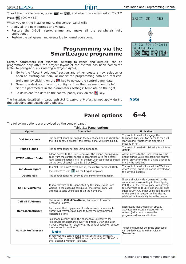
42 Options and programming methods
Installation and Programming Manual
To exit the installer menu, press or , and when the system asks: “EXIT?”Press (OK = YES).
When you exit the installer menu, the control panel will:• Apply all the new settings and values.• Restore the I-BUS, reprogramme and make all the peripherals fully
operational.• Restore the call queue, and events log to normal operations.
6-3Programming via theSmartLeague programme
Certain parameters (for example, relating to zones and outputs) can beprogrammed only after the project layout of the system has been completed(refer to paragraph 5-3 Creating a Project layout).
1. Go to the “Recent solutions” section and either create a new solution oropen an existing solution, or import the programming data of a real con-trol panel by clicking on the key to upload the control panel data.
2. Select the device you wish to configure from the tree menu on the left.3. Set the parameters in the “Parameters settings” template on the right.
4. To download the data to the control panel, click-on the key.
NoteThe limitations described in paragraph 5-3 Creating a Project layout apply duringthe uploading and downloading phases.
6-4Panel optionsThe following options are provided by the control panel.
EXIT? OK = YES
18:23 30/10/2011DASIDASI--
Table 31: Panel optionsOption If enabled If disabled
Dial tone check The control panel will engage the telephone line and check for the “dial tone”, if present, the control panel will start dialing.
The control panel will engage the telephone line, wait two seconds then will start dialing (whether the dial tone is present or not).
Pulse dialing The control panel will dial using pulse tone. The control panel will dial using touch tone (DTMF).
DTMF withoutCodeAllows access to the User Menu over-the-phone (during voice calls from the control panel) in accordance with the access level (enabled options, etc.) of the last user code that operated on the control panel (code 30, 50 or 100).
Allows access to the User Menu over-the-phone during voice calls from the control panel, only after entry of a valid user-code PIN by the recipient.
Line down signalIf a “Tel.Line down” event occurs, the control panel will flash the respective icon on the keypad displays.
The control panel will detect the “Tel.Line down” event, but it will not be revealed on the keypad displays.
Double call The control panel will override the answerphone function.
Call allVoxNumsIf several voice calls - generated by the same event - are waiting in the outgoing call queue, the control panel will attempt to send voice calls to all the numbers.
If several voice calls - generated by the same event - are waiting in the outgoing Call Queue, the control panel will attempt to send voice calls until just one call ends successfully. Any other voice calls relating to the event in question will be cleared (deleted) automatically from the queue .
Call all TLVNums The same as Call all VoxNums, but related to Alarm Receiving Centres.
RefreshMnstblOutEach event that triggers an already-activated monostable output will refresh (take back to zero) the programmed Monostable time.
Each event that triggers an already-activated monostable output will not refresh (take back to zero) the programmed Monostable time.
Num10 ForTeleserv
Telephone number 10 in the phonebook is reserved for Teleservice (maintenance over-the-phone). If an end-user makes a request for Teleservice, the control panel will contact the number in position 10.
NoteIf you wish the control panel to call an installer company number which uses an INIM modem, you must set “None” in the Telephone Number Type field.
Telephone number 10 in the phonebook can be dedicated to either voice or Teleservice.
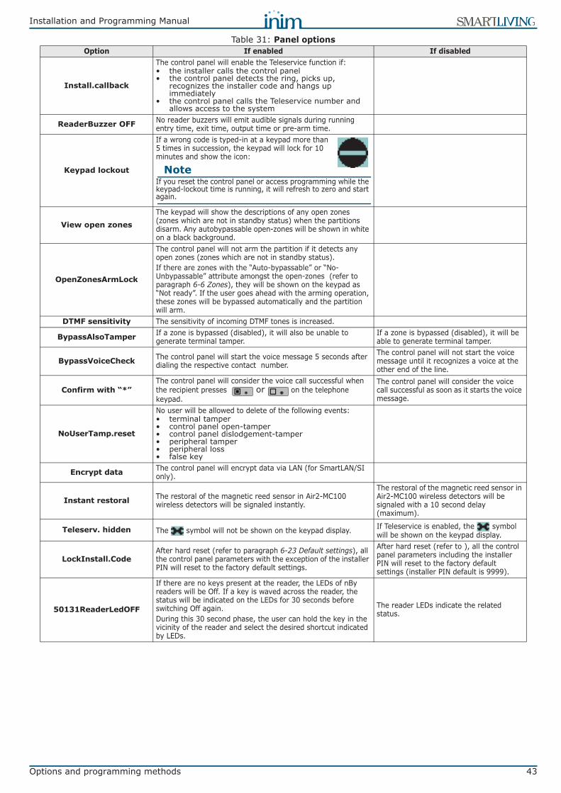
Installation and Programming Manual
Options and programming methods 43
Install.callback
The control panel will enable the Teleservice function if:• the installer calls the control panel• the control panel detects the ring, picks up,
recognizes the installer code and hangs up immediately
• the control panel calls the Teleservice number and allows access to the system
ReaderBuzzer OFF No reader buzzers will emit audible signals during running entry time, exit time, output time or pre-arm time.
Keypad lockout
If a wrong code is typed-in at a keypad more than 5 times in succession, the keypad will lock for 10 minutes and show the icon:
NoteIf you reset the control panel or access programming while the keypad-lockout time is running, it will refresh to zero and start again.
View open zonesThe keypad will show the descriptions of any open zones (zones which are not in standby status) when the partitions disarm. Any autobypassable open-zones will be shown in white on a black background.
OpenZonesArmLock
The control panel will not arm the partition if it detects any open zones (zones which are not in standby status).If there are zones with the “Auto-bypassable” or “No-Unbypassable” attribute amongst the open-zones (refer to paragraph 6-6 Zones), they will be shown on the keypad as “Not ready”. If the user goes ahead with the arming operation, these zones will be bypassed automatically and the partition will arm.
DTMF sensitivity The sensitivity of incoming DTMF tones is increased.
BypassAlsoTamper If a zone is bypassed (disabled), it will also be unable to generate terminal tamper.
If a zone is bypassed (disabled), it will be able to generate terminal tamper.
BypassVoiceCheck The control panel will start the voice message 5 seconds after dialing the respective contact number.
The control panel will not start the voice message until it recognizes a voice at the other end of the line.
Confirm with “*”The control panel will consider the voice call successful when the recipient presses or on the telephone keypad.
The control panel will consider the voice call successful as soon as it starts the voice message.
NoUserTamp.reset
No user will be allowed to delete of the following events:• terminal tamper• control panel open-tamper• control panel dislodgement-tamper• peripheral tamper• peripheral loss• false key
Encrypt data The control panel will encrypt data via LAN (for SmartLAN/SI only).
Instant restoral The restoral of the magnetic reed sensor in Air2-MC100 wireless detectors will be signaled instantly.
The restoral of the magnetic reed sensor in Air2-MC100 wireless detectors will be signaled with a 10 second delay (maximum).
Teleserv. hidden The symbol will not be shown on the keypad display. If Teleservice is enabled, the symbol will be shown on the keypad display.
LockInstall.CodeAfter hard reset (refer to paragraph 6-23 Default settings), all the control panel parameters with the exception of the installer PIN will reset to the factory default settings.
After hard reset (refer to ), all the control panel parameters including the installer PIN will reset to the factory default settings (installer PIN default is 9999).
50131ReaderLedOFF
If there are no keys present at the reader, the LEDs of nBy readers will be Off. If a key is waved across the reader, the status will be indicated on the LEDs for 30 seconds before switching Off again.During this 30 second phase, the user can hold the key in the vicinity of the reader and select the desired shortcut indicated by LEDs.
The reader LEDs indicate the related status.
Table 31: Panel optionsOption If enabled If disabled

44 Options and programming methods
Installation and Programming Manual
6-5TerminalsThis section describes the configuration flexibility of the system terminals. Theprofile of each terminal can be configured as follows.• Programme the type of terminal:
•• Input (I) •• Output (O) •• Two way - supervised output (T) •• Double Zone (D) •• Unused (-)
• Programme the parameters related to the selected configuration
ATTENTION!For critical events or events of particular importance, it is advisable to usekeypad terminals T1 and T2 as the signal outputs. The status of these outputsmay switch (On to Off and vice versa) in the event of BUS reset.
50131StatHidden
The status of the partitions will be hidden. If a valid code is entered at a keypad, the real-time status will be indicated on the keypad concerned for 30 seconds.If the partitions are armed, the status of the system will be hidden from non-authorized users.• Red keypad LED Off• Yellow keypad LED Off• Green keypad LED On solid• Status icons not present• Alarm and Tamper memory hidden• If a particular event occurs more than 5 times when
the partitions are armed, it will not be signaled ashaving occurred more than 5 times. This is due tothe limitation placed on the counter of each event.The counters will reset to zero each time all thepartitions are disarmed.
If the partitions are DISARMED:• The LEDs will function normally.• Status icons present• Alarm and Tamper memory visible
The keypad will show the real-time status of the system at all times, regardless of the status of its partitions.
50131IconsHidden
If partitions are armed, the status icons will be hidden from non-authorized users.If a valid code is entered at a keypad, the status of the icons will be shown for 30 seconds.The keypad will show the real-time status of the icons when all the keypad partitions are disarmed.
The keypad will show the real-time status of the icons at all times, regardless of the status of its partitions.
50131AlarDelayed
If an instant-zone alarm occurs on a partition while entry time is running, the associated actions (calls, output activation, save to log, etc.) will not be generated until 30 seconds after the expiry of the entry time.If the partition (or partitions) are disarmed during this period, the associated actions will not be generated, however, the keypads will indicate the violation of the instant zone.
If an instant-zone alarm occurs on a partition while entry time is running, the associated actions (calls, output activation, save to log, etc.) will be activated instantly.
50131WarnLedMem
If the control panel detects a fault, the yellow LED on the keypads will go On and will remain On even after the fault clears.To switch the yellow LED Off, clear all activating causes and reset the partition.
If the control panel detects a fault, the yellow LED on the keypads will go On and will go Off automatically when the fault clears.
DayLightSav.timeThe control panel clock will go back automatically one hour at 03:00 last Sunday in October, and it will go forwards automatically one hour at 02:00 last Sunday in March.
No automatic clock forward/back operations.
NoStringsSiaProt The descriptive strings will not be sent in SIA reporting format. The descriptive strings will be sent in SIA reporting format.
Nexus prior Voice calls will be diverted to Nexus dialer. Voice calls will be diverted to Nexus dialer only when the PSTN line is down.
Invert CONTACT-IDPartition arming events using CONTACT-ID reporting format will send the "New event/Event activation" code when the partition is armed and the "Event ended/Event restore" when the partition is disarmed.
Partition arming events using CONTACT-ID reporting format will send the "New event/Event activation" code when the partition is disarmed and the "Event ended/Event restore" when the partition is armed.
Table 31: Panel optionsOption If enabled If disabled
Patent pending

Installation and Programming Manual
Options and programming methods 45
Via Keypad1. Access the “Programming Terminals” section.
Type-in Code (Installer PIN) , PROGRAMMING Terminals .
The display will show the:1° riga: the number of terminals2° line: the type of terminals and the selected terminal3° line: the description of the selected terminal4° line: the description of the second zone of the selected terminal if it config-
ured as a DOUBLE ZONE.2. Use and to select the device whose terminals you wish to config-
ure. The terminals are arranged as follows:• terminals from 1 to 5 on the control panel• terminals from 6 to 10 on the control panel (SmartLiving 1050 and 10100)• terminals on expansion boards• terminals on keypads
3. Use and to scroll across the terminals. The selected terminal willblink. Configure the terminal by pressing:
• to configure the terminal as an INPUT (“I”)• to configure the terminal as an OUTPUT (“O”)• to configure the terminal as a TWO WAY - SUPERVISED OUTPUT (“T”)• to configure the terminal as a DOUBLE ZONE (“D”)• to configure the terminal as UNUSED (“-”)• to enable/disable the terminal as “Wireless”
4. Once you have configured the terminal, press , , , or to
configure its type.If an UNUSED terminal is configured as I, O, T or D and the keypad emits anerror “beep”, it means that you have exceeded the maximum number ofterminals available on the control panel. If you wish to employ the terminalconcerned, you must first configure another terminal as UNUSED.
If you are working on a Flex5 expansion terminal, press key to configure it,and consequently the entire expansion, as wireless. The “Wireless” string will beshown on the bottom line of the display. If you press key again, theoperation will undo.To configure a terminal as a wireless output, proceed as follows:
1. Position the cursor on the terminal concerned.2. Press to configure the terminal, and consequently the entire expan-
sion, as wireless.3. Configure the terminal as an “input” ( ).
4. Press to access the zone parameters programming section.5. Go to the “Wireless” section.6. Enroll the terminal as “Input 1 C.M.” or “Input 2 C.M.”7. Press the “ENROLL” button on the Air2-MC100 device.8. Enable the “Broadcast RF” option as follows:
Type in Code (Installer) , PROGRAMMING Zones , select the zone, Options , BroadcastRF.
NoteThe “Broadcast RF” option must be enabled for each terminal of the Air2-MC100 deviceconcerned.
9. Go back to step 1 and configure the terminal as an output ( ).
10. Press to access the output parameters programming section (descrip-tion, options, etc.).
Press in correspondence with any terminal, provided that it is not an UNUSEDterminal, to access the parameter programming section of the type of terminalselected, whether it is a zone or an output (refer to paragraph 6-6 Zones orparagraph 6-7 Outputs).
Via PC
PROGRAMMINGPanel optionsTerminalsZones
Terminals 12345Panel 1-5 IOTD-Panel T01
To configure a wireless terminal as an
“output”, you must first enroll it as an
“input”, and then programme it as an “output”, as described in the instructions (see opposite).
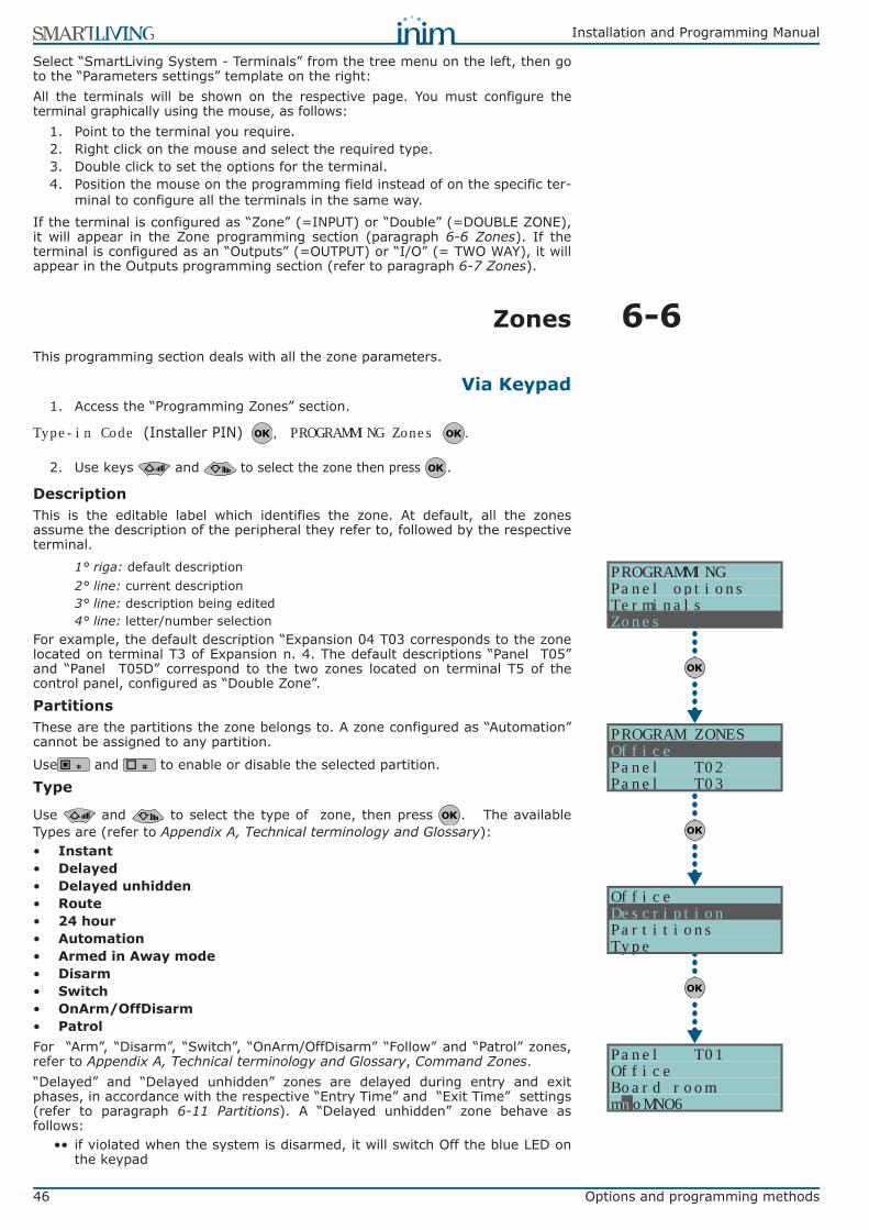
46 Options and programming methods
Installation and Programming Manual
Select “SmartLiving System - Terminals” from the tree menu on the left, then goto the “Parameters settings” template on the right:All the terminals will be shown on the respective page. You must configure theterminal graphically using the mouse, as follows:
1. Point to the terminal you require.2. Right click on the mouse and select the required type.3. Double click to set the options for the terminal.4. Position the mouse on the programming field instead of on the specific ter-
minal to configure all the terminals in the same way.If the terminal is configured as “Zone” (=INPUT) or “Double” (=DOUBLE ZONE),it will appear in the Zone programming section (paragraph 6-6 Zones). If theterminal is configured as an “Outputs” (=OUTPUT) or “I/O” (= TWO WAY), it willappear in the Outputs programming section (refer to paragraph 6-7 Zones).
6-6ZonesThis programming section deals with all the zone parameters.
Via Keypad1. Access the “Programming Zones” section.
Type-in Code (Installer PIN) , PROGRAMMING Zones .
2. Use keys and to select the zone then press .
DescriptionThis is the editable label which identifies the zone. At default, all the zonesassume the description of the peripheral they refer to, followed by the respectiveterminal.
1° riga: default description2° line: current description3° line: description being edited4° line: letter/number selection
For example, the default description “Expansion 04 T03 corresponds to the zonelocated on terminal T3 of Expansion n. 4. The default descriptions “Panel T05”and “Panel T05D” correspond to the two zones located on terminal T5 of thecontrol panel, configured as “Double Zone”.
PartitionsThese are the partitions the zone belongs to. A zone configured as “Automation”cannot be assigned to any partition.
Use and to enable or disable the selected partition.
Type
Use and to select the type of zone, then press . The availableTypes are (refer to Appendix A, Technical terminology and Glossary):• Instant• Delayed• Delayed unhidden• Route• 24 hour• Automation• Armed in Away mode• Disarm• Switch• OnArm/OffDisarm• PatrolFor “Arm”, “Disarm”, “Switch”, “OnArm/OffDisarm” “Follow” and “Patrol” zones,refer to Appendix A, Technical terminology and Glossary, Command Zones.“Delayed” and “Delayed unhidden” zones are delayed during entry and exitphases, in accordance with the respective “Entry Time” and “Exit Time” settings(refer to paragraph 6-11 Partitions). A “Delayed unhidden” zone behave asfollows:
•• if violated when the system is disarmed, it will switch Off the blue LED onthe keypad
OfficeDescriptionPartitionsType
PROGRAMMINGPanel optionsTerminalsZones
PROGRAM ZONESOfficePanel T02Panel T03
Panel T01OfficeBoard roomm oMNO6n
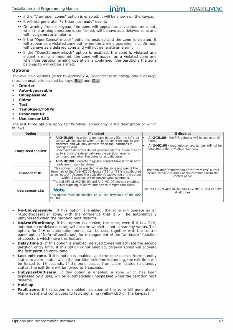
Installation and Programming Manual
Options and programming methods 47
•• if the “View open zones” option is enabled, it will be shown on the keypad•• it will not generate “Partition not ready” events•• On arming from a keypad, the zone will appear as a violated zone but,
when the arming operation is confirmed, will behave as a delayed zone andwill not generate an alarm.
•• if the “OpenZonesArmLock” option is enabled and the zone is violated, itwill appear as a violated zone but, when the arming operation is confirmed,will behave as a delayed zone and will not generate an alarm.
•• if the “OpenZonesArmLock” option is enabled, the zone is violated andinstant arming is required, the zone will appear as a violated zone andwhen the partition arming operation is confirmed, the partitions the zonebelongs to will not be armed.
OptionsThe available options (refer to Appendix A, Technical terminology and Glossary)must be enabled/disabled by keys and :• Interior• Auto-bypassable• Unbypassable• Chime• Test• TampReed/FollPir• Broadcast RF• Use sensor LEDThe last three options apply to “Wireless” zones only, a full description of whichfollows.
• No-Unbypassable If this option is enabled, the zone will operate as an“Auto-bypassable” zone, with the difference that it will be automaticallyunbypassed when the partition next disarms.
• NoArmIfNotReady. If this option is enabled, the zone, even if it is a 24H,automation or delayed zone, will not arm when it is not in standby status. Thisoption, for 24H or automation zones, can be used together with the controlpanel option “NoArmOpenZones”, for management of the “antimask” functionof detectors which have this feature.
• Delay time 2. If this option is enabled, delayed zones will activate the secondpartition entry time. If this option is not enabled, delayed zones will activatethe first partition entry time.
• Last exit zone. If this option is enabled, and the zone passes from standbystatus to alarm status while the partition exit time is running, the exit time willbe forced to 15 seconds. If the zone passes from alarm status to standbystatus, the exit time will be forced to 5 seconds.
• UnbypassOnDisarm. If this option is enabled, a zone which has beenbypassed by a user, will be automatically unbypassed when the partition nextdisarms.
• Hold-up.• Fault zone. If this option is enabled, violation of the zone will generate an
Alarm event and contributes to fault signaling (yellow LED on the keypad).
Option If enabled If disabled
TampReed/FollPir
• Air2-IR100 - in order to increase battery life, the infrared sensor will deactivate when the partitions it belongs to are disarmed and will only activate when the partitions it belongs to arm.Deactivated detectors do not generate alarms. There may be up to a 3 minute delay between the partition arming command and when the detector actually arms.
• Air2-MC100 - detects magnetic-contact tamper when both reeds are in standby status.
• Air2-IR100 - the PIR detector will be active at all times.
• Air2-MC100 - magnetic-contact tamper will not be detected under any circumstances.
Broadcast RFThis option must be enabled when the zone and one of the
terminals of the Air2-MC100 device (“T1” or “T2”) is configured as an “output”. Assures the activation/deactivation of the output
within 2 seconds of the control panel command.
The activation/deactivation of the “wireless” output occurs within 2 minutes of the command from the
control panel.
Use sensor LED
The red LED of Air2-IR100 and Air2-MC100 devices provides visual signaling of alarm and device tamper conditions.
NoteThis option must be enabled on all the terminals of the Air2-MC100.
The red LED of Air2-IR100 and Air2-MC100 will be “Off” at all times.

48 Options and programming methods
Installation and Programming Manual
Wireless
NotePlease note that this section will be operative only when the zone you are working on isconfigured as a wireless zone (refer to paragraph 6-5 Terminals).
This section allows you to carry out all the operations relating to theprogramming of Air2 wireless series devices. The wireless-device programmingsection is arranged as follows.• Enroll sensor - allows you to enroll a wireless detector which has not yet
been enrolled on the terminal concerned.
Press to initialize the enrollment process. Select the type of detector you wishto enroll:
•• PIR sensor - allows you to enroll an Air2-IR100 detector•• Magnetic contact - allows you to enroll Air2-MC100 magnetic reed contact•• Terminal T1 MC - allows you to enroll the “T1” terminal of an Air2-MC100•• Terminal T2 MC - allows you to enroll the “T2” terminal of an Air2-MC100
After selecting the desired type, press . The first line of the keypad will showthe “Programming” string.To enroll the wireless device, press and release its on-board “ENROLL” button. Assoon as the enrolling process is complete, the keypad will emit an audible signal(beep) to confirm the operation, and will show (in accordance with the type ofdevice) the following:• Delete sensor - allows you to delete (unenroll) an enrolled wireless detector
from the terminal concerned.• PIR sensor - allows you to change the parameters of an already enrolled
Air2-IR100 detector. Press to programme the detector sensitivity andenter a value of between 1 (low sensitivity) and 4 (high sensitivity).
1. Use keys or to select the field you wish to change, then use thenumber keys ( , etc.) to edit the number.
orUse key or to increase or decrease the number.
2. Press to confirm and exit.• Magnetic contact - allows you to change the parameters of an already
enrolled Air2-MC100 magnetic contact. Press , to access the followingoptions:•• LongSide contact - detection using the long side of the magnetic contact.•• ShortSideContact - detection using the short side of the magnetic contact.•• Both contacts - detection using both sides of the magnetic contact.
If you select the “Both contacts” option, standby status will be detected wheneither (or both) of the 2 reeds close. If you select either “LongSide contact” or“ShortSideContact”, standby status will be detected when the selected reedcloses and the other opens. If both reeds close, the system will generate aterminal-tamper event. In fact, the most common method of jamming this typeof device is to hold a magnet in the vicinity of the magnetic contact, should thisever occur, both reed relays will close to trigger a tamper event.• Terminal T1 M.C. and Terminal T2 M.C. - to change the parameters of
terminal “T1” of an enrolled Air2-MC100. If you press at this point, thekeypad will step back to the Zones menu and you can set up the parametersof the terminal: Balancing, Rollerblind, Times, etc.
Terminals “T1” and/or “T2” of the Air2-MC100 device can be set up in the sameway as wired terminals, with the exception that wireless terminals cannot beconfigured as “double zones”.
BalancingBalancing can be (refer to Appendix A, Technical terminology and Glossary andparagraph 3-5 Wiring and balancing alarm detectors):• Norm. open (NO)• Norm.closed (NC)• Single balancing• Double balancing• Double Zone (without EOL)• Double Zone EOL (with EOL)
Programming
WirelessEnroll detector
Enroll detectorPIR detectorMagnetic ContactTerminal T1 MC
Sensibility00_ Units(Min. 001(Max. 004)
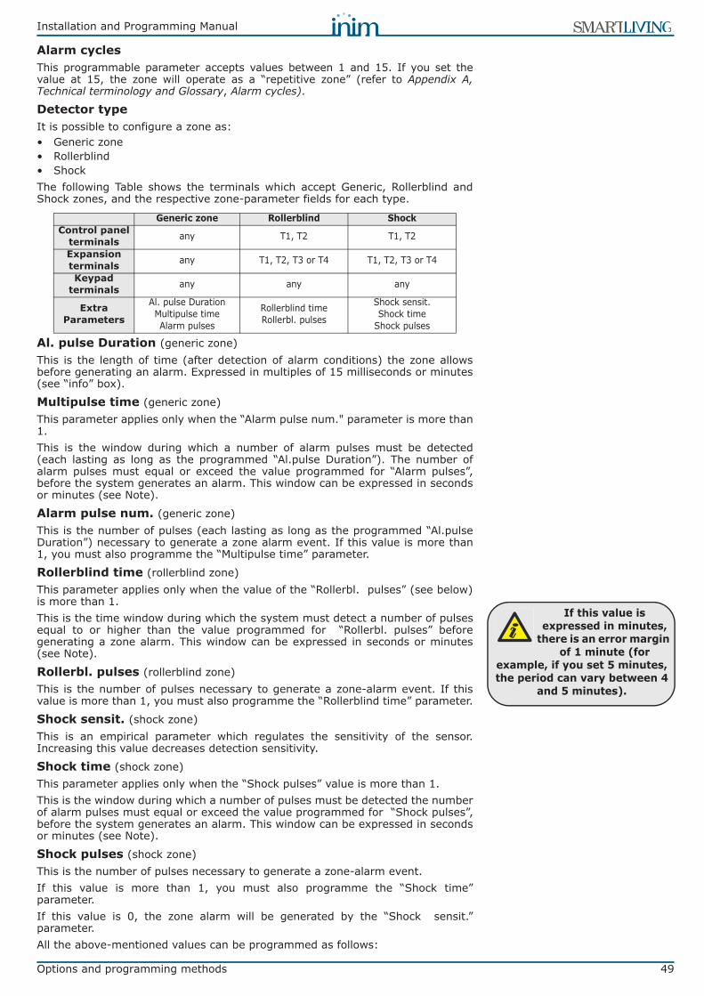
Installation and Programming Manual
Options and programming methods 49
Alarm cyclesThis programmable parameter accepts values between 1 and 15. If you set thevalue at 15, the zone will operate as a “repetitive zone” (refer to Appendix A,Technical terminology and Glossary, Alarm cycles).
Detector typeIt is possible to configure a zone as:• Generic zone• Rollerblind• ShockThe following Table shows the terminals which accept Generic, Rollerblind andShock zones, and the respective zone-parameter fields for each type.
Al. pulse Duration (generic zone)This is the length of time (after detection of alarm conditions) the zone allowsbefore generating an alarm. Expressed in multiples of 15 milliseconds or minutes(see “info” box).
Multipulse time (generic zone)This parameter applies only when the “Alarm pulse num." parameter is more than1. This is the window during which a number of alarm pulses must be detected(each lasting as long as the programmed “Al.pulse Duration”). The number ofalarm pulses must equal or exceed the value programmed for “Alarm pulses”,before the system generates an alarm. This window can be expressed in secondsor minutes (see Note).
Alarm pulse num. (generic zone)This is the number of pulses (each lasting as long as the programmed “Al.pulseDuration”) necessary to generate a zone alarm event. If this value is more than1, you must also programme the “Multipulse time” parameter.
Rollerblind time (rollerblind zone)This parameter applies only when the value of the “Rollerbl. pulses” (see below)is more than 1.This is the time window during which the system must detect a number of pulsesequal to or higher than the value programmed for “Rollerbl. pulses” beforegenerating a zone alarm. This window can be expressed in seconds or minutes(see Note).
Rollerbl. pulses (rollerblind zone)This is the number of pulses necessary to generate a zone-alarm event. If thisvalue is more than 1, you must also programme the “Rollerblind time” parameter.
Shock sensit. (shock zone)This is an empirical parameter which regulates the sensitivity of the sensor.Increasing this value decreases detection sensitivity.
Shock time (shock zone)This parameter applies only when the “Shock pulses” value is more than 1.This is the window during which a number of pulses must be detected the numberof alarm pulses must equal or exceed the value programmed for “Shock pulses”,before the system generates an alarm. This window can be expressed in secondsor minutes (see Note).
Shock pulses (shock zone)This is the number of pulses necessary to generate a zone-alarm event.If this value is more than 1, you must also programme the “Shock time”parameter.If this value is 0, the zone alarm will be generated by the “Shock sensit.”parameter.All the above-mentioned values can be programmed as follows:
Generic zone Rollerblind ShockControl panel
terminals any T1, T2 T1, T2
Expansion terminals any T1, T2, T3 or T4 T1, T2, T3 or T4
Keypad terminals any any any
Extra Parameters
Al. pulse DurationMultipulse timeAlarm pulses
Rollerblind timeRollerbl. pulses
Shock sensit.Shock time
Shock pulses
If this value is expressed in minutes,
there is an error margin of 1 minute (for
example, if you set 5 minutes, the period can vary between 4
and 5 minutes).
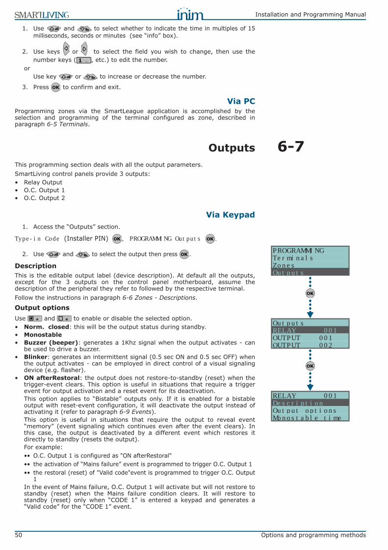
50 Options and programming methods
Installation and Programming Manual
1. Use and to select whether to indicate the time in multiples of 15milliseconds, seconds or minutes (see “info” box).
2. Use keys or to select the field you wish to change, then use thenumber keys ( , etc.) to edit the number.
orUse key or to increase or decrease the number.
3. Press to confirm and exit.
Via PCProgramming zones via the SmartLeague application is accomplished by theselection and programming of the terminal configured as zone, described inparagraph 6-5 Terminals.
6-7OutputsThis programming section deals with all the output parameters.SmartLiving control panels provide 3 outputs:• Relay Output• O.C. Output 1• O.C. Output 2
Via Keypad1. Access the “Outputs” section.
Type-in Code (Installer PIN) , PROGRAMMING Outputs .
2. Use and to select the output then press .
DescriptionThis is the editable output label (device description). At default all the outputs,except for the 3 outputs on the control panel motherboard, assume thedescription of the peripheral they refer to followed by the respective terminal.Follow the instructions in paragraph 6-6 Zones - Descriptions.
Output optionsUse and to enable or disable the selected option.• Norm. closed: this will be the output status during standby.• Monostable • Buzzer (beeper): generates a 1Khz signal when the output activates - can
be used to drive a buzzer.• Blinker: generates an intermittent signal (0.5 sec ON and 0.5 sec OFF) when
the output activates - can be employed in direct control of a visual signalingdevice (e.g. flasher).
• ON afterRestoral: the output does not restore-to-standby (reset) when thetrigger-event clears. This option is useful in situations that require a triggerevent for output activation and a reset event for its deactivation.This option applies to “Bistable” outputs only. If it is enabled for a bistableoutput with reset-event configuration, it will deactivate the output instead ofactivating it (refer to paragraph 6-9 Events).This option is useful in situations that require the output to reveal event“memory” (event signaling which continues even after the event clears). Inthis case, the output is deactivated by a different event which restores itdirectly to standby (resets the output).For example:•• O.C. Output 1 is configured as "ON afterRestoral"•• the activation of “Mains failure” event is programmed to trigger O.C. Output 1•• the restoral (reset) of "Valid code"event is programmed to trigger O.C. Output
1In the event of Mains failure, O.C. Output 1 will activate but will not restore tostandby (reset) when the Mains failure condition clears. It will restore tostandby (reset) only when “CODE 1” is entered a keypad and generates a“Valid code” for the “CODE 1” event.
RELAY 001DescriptionOutput optionsMonostable time
PROGRAMMINGTerminalsZonesOutputs
OutputsRELAY 001OUTPUT 001OUTPUT 002
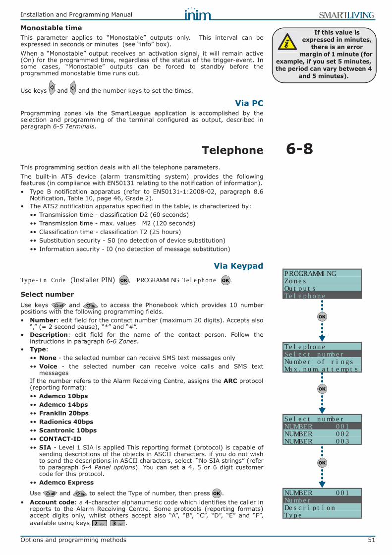
Installation and Programming Manual
Options and programming methods 51
Monostable timeThis parameter applies to “Monostable” outputs only. This interval can beexpressed in seconds or minutes (see “info” box).When a “Monostable” output receives an activation signal, it will remain active(On) for the programmed time, regardless of the status of the trigger-event. Insome cases, “Monostable” outputs can be forced to standby before theprogrammed monostable time runs out.
Use keys and and the number keys to set the times.
Via PCProgramming zones via the SmartLeague application is accomplished by theselection and programming of the terminal configured as output, described inparagraph 6-5 Terminals.
6-8TelephoneThis programming section deals with all the telephone parameters.The built-in ATS device (alarm transmitting system) provides the followingfeatures (in compliance with EN50131 relating to the notification of information).• Type B notification apparatus (refer to EN50131-1:2008-02, paragraph 8.6
Notification, Table 10, page 46, Grade 2).• The ATS2 notification apparatus specified in the table, is characterized by:
•• Transmission time - classification D2 (60 seconds)•• Transmission time - max. values M2 (120 seconds)•• Classification time - classification T2 (25 hours)•• Substitution security - S0 (no detection of device substitution)•• Information security - I0 (no detection of message substitution)
Via KeypadType-in Code (Installer PIN) , PROGRAMMING Telephone .
Select numberUse keys and to access the Phonebook which provides 10 numberpositions with the following programming fields. • Number: edit field for the contact number (maximum 20 digits). Accepts also
“,” (= 2 second pause), “*” and “#”.• Description: edit field for the name of the contact person. Follow the
instructions in paragraph 6-6 Zones.• Type:
•• None - the selected number can receive SMS text messages only•• Voice - the selected number can receive voice calls and SMS text
messagesIf the number refers to the Alarm Receiving Centre, assigns the ARC protocol(reporting format):•• Ademco 10bps •• Ademco 14bps•• Franklin 20bps •• Radionics 40bps •• Scantronic 10bps •• CONTACT-ID •• SIA - Level 1 SIA is applied This reporting format (protocol) is capable of
sending descriptions of the objects in ASCII characters. if you do not wishto send the descriptions in ASCII characters, select “No SIA strings” (referto paragraph 6-4 Panel options). You can set a 4, 5 or 6 digit customercode for this protocol.
•• Ademco Express
Use and to select the Type of number, then press .• Account code: a 4-character alphanumeric code which identifies the caller in
reports to the Alarm Receiving Centre. Some protocols (reporting formats)accept digits only, whilst others accept also “A”, “B”, “C”, “D”, “E” and “F”,available using keys .
If this value is expressed in minutes,
there is an error margin of 1 minute (for
example, if you set 5 minutes, the period can vary between 4
and 5 minutes).
PROGRAMMINGZonesOutputsTelephone
TelephoneSelect numberNumber of ringsMax.num.attempts
Select numberNUMBER 001NUMBER 002NUMBER 003
NUMBER 001NumberDescriptionType
52 Options and programming methods
Installation and Programming Manual
• Partitions: you can associate each telephone number with specific partitions.By selecting the partitions, using Keys and , you enable/disable theusers (who have at least one of these partitions in common with the telephonenumber) to modify the number concerned.
Number of ringsThis value determines the number of rings the system allows before picking up anincoming call.
Max.num.attemptsThis value determines the number of calls attempts the system will make beforedeleting the contact number from the call queue.
Message repeatsThis value determines the number of times the voice message will be playedduring the call.All the above-mentioned values can be programmed as follows:
1. Use keys or to select the field you wish to change, then use thenumber keys ( , etc.) to edit the number.
orUse key or to increase or decrease the number.
2. Press to confirm and exit.
Via PC
Via the SmartLeague software programme, you can enable the “Enable toreceive SMS text messages” option which (in addition to the other signalsprogrammed for when the event occurs) enables the telephone number toreceive an SMS text message from the Nexus GSM dialer.
6-9EventsThis programming section deals with all the event-generated output actions.The control panel recognizes all of the events described in this paragraph and, foreach them, in accordance with programming, can generate actions both when theevent occurs and when it restores/ends.The operations that can be carried out at the control panel are: output activation,event notification via telephone, save to event memory, voice messagemanagement, voice message management and management of all the optionsrelative to each event. These actions are triggered as soon as the event occurs(or restores).Telephone notifications (calls) are queued and sent out in chronological order.However, some events may need to be notified immediately (for example, use ofa code under duress), therefore, such events can be given priority by selectingthe “Priority” option.Event notification via e-mail requires the use of a SmartLAN/G board (refer toparagraph 3-10-4 SmartLAN).Event notification via predefined SMS messages requires the use of a Nexus(refer to paragraph 6-26-4 Text for SMS messages).The following table shows the events the control panel recognizes, the number ofevents for each type, the trigger and restoral method of each event and the eventcategory (Pulse).
Table 32: Telephone - via the SmartLeague software programmeOption Part of the system Template/section
Select number
SmartLiving System - Telephone
Programming
Number of rings Parameters settings - Telephone line parameters
Max.num.attempts Parameters settings - Telephone dialer parametersMessage repeats

Installation and Programming Manual
Options and programming methods 53
Table 33: Event type
Name Occurs when... Restores when ... Number of events Pulse events
Zone alarm A zone generates an alarm A zone restores One event for each zone no
Terminal tamper A terminal detects tamper (short-circuit or wire cutting) A terminal restores One event for each
terminal no
Partition alarmA 24h zone which belongs to the partition
generates an alarm, or a zone which belongs to the partition generates an alarm during
Away mode.
All the zones belonging to the partition restore (reset).
One event for each partition no
StayPartit.alarm A zone which belongs to a partition armed in Stay or Instant mode, generates an alarm.
All the zones belonging to the partition restore (reset).
One event for each partition no
Partition tamper A zone which belongs to the partition detects tamper (short-circuit or wire cutting).
All the zones belonging to the partition restore (reset).
One event for each partition no
Zone bypass A zone is inhibited A zone is enabled (switched On) One event for each zone no
Real-time zone
The electrical status of a zone switches from standby to alarm
The electrical status of a zone switches from alarm to standby One event for each
zone noThe event is independent of the zone type and the armed/disarmed status of the
partitions.
Partit.not ready A zone which belongs to the partition is not in standby status.
All the zones belonging to the partition are in standby status.
One event for each partition no
Away arm request A request is made to arm the interior and perimeter zones of the partition
A request is made to disarm the partition
One event for each partition Yes
Overtime requestA request is made to arm the partition in Stay
mode (perimeter zones only) or in Instant mode
A request is made to disarm the partition
One event for each partition Yes
Partit.AwayArmed The partition interior and perimeter zones have been armed effectively
The partition has been disarmed effectively
One event for each partition no
Partit.StayArmed armed
The partition has been armed effectively in Stay or Instant mode
The partition has been disarmed effectively
One event for each partition no
Partition reset A request is made to reset the partition One event for each partition Yes
Exit time The partition exit time is running The partition exit time expires One event for each partition no
Entry time The partition entry time is running The partition entry time expires One event for each partition no
Pre-arm time The partition Pre-arm time is running The partition Pre-arm time expires One event for each partition no
Overtime request A request for overtime relating to the partition is made
One event for each partition Yes
Chime A chime zone belonging to the partition is violated
One event for each partition Yes
Forced arming
At the time of an arming command, relating to one or more partitions, there are open
zones on the partition/partitions involved, or there are other conditions present which
lower system security, nonetheless, the user arms the system.
One event for each partition Yes
Failed to arm
The “OpenZonesArmLock” option is enabled at the time of a partition arming command and there is at least one open zone on the
partition/s involved.or
when one or more of the conditions described in “LossTamp.ongoing” is present (refer to
“FaultNotReady”, paragraph 6-25 Other parameters).
One event for each partition Yes
Valid code A user-code PIN entered at a keypad is recognized as valid
One event for each code Yes
Valid key A key used at a reader is recognized as valid on the reader
One event for each key Yes
Valid Code AtKeyp. A user-code PIN entered at a keypad is recognized as valid on the keypad
One event for each keypad Yes
ValidKeyAtReader A key used at a reader is recognized as valid on the reader
One event for each reader Yes
Partition code A user-code PIN entered at a keypad is recognized as valid on the partition
One event for each partition Yes
Partition key A key used at a reader is recognized as valid on the partition
One event for each partition Yes
Failed call A call is not answered One event for each contact telephone
numberYes
Timer activated The timer is enabled (On) The timer is disabled (Off) One event for each timer no
Thermostat ON The activation conditions set for the keypad thermostat occur.
The deactivation conditions set for the keypad thermostat occur.
One event for each keypad no
54 Options and programming methods
Installation and Programming Manual
Each event can be associated with 3 voice messages, selected from the messagelist (refer to Appendix D, Voice messages).• Message type• Message A• Message BThis feature allows you to create messages which will be played during event-related voice calls to contact numbers, both at the start and end of the event.The choice of messages and the number of times they are played depends on the“AutomaticDialer” settings.
Scenario ON The status of all the partitions corresponds exactly to the pre-set scenario.
The status of all least one of the partitions does not correspond to the
pre-set scenario.One event for each
scenario no
ProgrammableEvt See paragraph 6-9-1 Programmable events no
Emergency key One of the emergency-key duos is pressed One event for each emergency-key duo Yes
Panel opened The control-panel enclosure cover is opened The control-panel enclosure cover is replaced 1 no
Dislodged panel 1 no
Zone fuse fault The zone protection fuse on the control panel is not operational (blown)
The zone protection fuse on the control panel restores 1 no
IBUS fuse fault The I-BUS protection fuse is not operational (blown) The I-BUS protection fuse restores 1 no
Low battery The backup battery is low(voltage below 10.4V)
The backup battery is charged(voltage above 11.4V) 1 no
Mains failure The primary 230V a.c. power source is absent (blackout)
The primary 230V a.c. power source restores 1 no
Expansion tamper An expansion board signals tamper conditions Tamper conditions clear on all the system expansion boards 1 no
Keypad tamper A keypad signals tamper conditions Tamper conditions clear on all the system keypads 1 no
Reader tamper A reader signals tamper conditions Tamper conditions clear on all the system readers 1 no
Sound.flash.Tamp A sounderflasher connected to the BUS signals tamper
All the sounderflashers connected to the BUS reset 1 no
Nexus tamper The GSM dialer Nexus signals tamper Tamper conditions clear on the Nexus 1 no
Expansion loss An expansion board cannot be found on the BUS
All expansion boards can be found on the BUS 1 no
Keypad loss A keypad cannot be found on the BUS All keypads can be found on the BUS 1 noReader loss A reader cannot be found on the BUS All readers can be found on the BUS 1 no
Sound.flash.Loss A sounderflasher cannot be found on the BUS All sounderflashers can be found on the BUS 1 no
Nexus loss The control panel is unable to communicate the Nexus 100
Communication between the control panel and the Nexus restores 1 no
Jamming Wireless interference detected Wireless interference cleared 1 no
Low battery WLS The battery of a least one wireless detector is running low
All the wireless detectors are running on low batteries 1 no
WLS zone loss Loss of at least one wireless detector has been signaled (supervisory time-out) All the wireless detector are present 1 no
Installer code An Installer PIN entered at a keypad is recognized as valid 1 Yes
Invalid code An invalid code is entered at a keypad 1 YesFalse key An invalid key is used at a reader 1 Yes
Nexus fault The GSM dialer Nexus signals a fault (see Chapter 7 - Errors and faults) Fault conditions clear on the Nexus 1 no
Tel. line down The land line is not working The land line restores 1 noPeriodic event The Periodic Event occurs 1 Yes
Hard reset The control panel re-initializes. The system clock may be wrong or not working properly. 1 Yes
Call queue full There are no more slots left in the outgoing call queue 1 Yes
Successful call The call is answered 1 YesProgramming Access to system programming is authorized End of system programming 1 noOngoing call A call is sent A call ends 1 no
SMSMessageFailed Nexus failed to send SMS message 1 Yes
Output fault An output fails to switch status as commanded 1 Yes
Table 33: Event type
Name Occurs when... Restores when ... Number of events Pulse events

Installation and Programming Manual
Options and programming methods 55
Via Keypad1. Accessing the “Events” section
Type-in Code (Installer PIN) , PROGRAMMING Events .
2. Use keys and to select the event type (if you are dealing with a group
of events, repeat the operation) then press .3. Select:
• Activation - to programme the actions to be carried out when the eventoccurs.
• Restoral - to programme the actions to be carried out when the event ends.
4. Successively, the parameters to programme are:
TelephoneNumbersProgramme the call recipient numbers
Message typeMessage AMessage BSelect the number of the message (see Table 34: Event-related messages andAppendix D, Voice messages):
1. Use keys or to select the field you wish to change, then use thenumber keys ( , etc.) to edit the number.
orUse keys and to increase or decrease the number.
2. Press to confirm and exit.
The following table shows the voice-message sequence in accordance with thepreviously mentioned parameters and options.
NoteIf an event is associated with the “Automatic dialer”, the “Type Message” option refers tomessages 261 to 312, that is to say, the messages containing the event descriptions(event types).
OptionsTo be activated by keys and :
EventsMessage AMessage BOptions
EventsTelephoneNumbersMessage typeMessage A
EventsActivationRestoral
Zone alarmPanel T01Panel T02Panel T03
PROGRAMMINGOutputsTelephoneEvents
EventsZone alarmTerminal tamperPartition alarm
Table 34: Event-related messages“Automatic dialer”
enabled“Automatic dialer”
disabled
Message typePlays the message relating to the event type (e.g. “zone alarm”, “Mains failure”)This message should not be changed.
You can select any message from 1 to 219
Message A Blank message, editable
Message B Contains event details, for events which are not distinctive (e.g. the “zone alarm” event provides information regarding the zone concerned).
Event Activation Sequence
1. Message type + 2602. Message A3. Message B4. “Location” (244)
1. Message type2. Message B3. “Location” (244)
Sequence in the event of
Restoral
1. “Restoral” (97)2. Message type3. Message A4. Message B5. “Location” (244)
1. Message A2. Message B3. “Location” (244)
Option If enabled If disabled
Event ON to log When the event occurs, it will be saved to the events log. When the event occurs, it will not be saved to the events log.
Event OFF to log When the event clears, it will be saved to the events log. When the event clears, it will not be saved to the events log.
StartPeriodicEv. When the event occurs, the system will generate the Periodic event.
Silent event If the event occurs, the system will generate silent calls which will not be signaled on the keypads.
If the event occurs, the system will generate calls which will be signaled on the keypads.
Clear call queue When the event occurs, the system will cancel the outgoing call queue.
Send addressIn the case of voice calls, the system will include the address of the location alarm (refer to the Table 34:
Event-related messages)
In the case of voice calls, the system will not include the address of the location alarm (refer to the Table 34:
Event-related messages)

56 Options and programming methods
Installation and Programming Manual
Class codeThis is the CONTACT-ID reporting format Class-Code which corresponds to the event.
Event codeThis is the 2-character alphanumeric code, which corresponds to the event sent thealarm receiving centre (ARC). For zone and terminal events (alarm, tamper,bypass), the “CCC” field of the CONTACT-ID protocol counts the number of hardterminals in accordance with the Hard terminals table (refer to Appendix E, ScrewTerminals).
OutputsWhen programming the Event-Activation section, you must programme the mainoutput which will be activated when the event occurs. When programming the Event-Restoral section, you must programme the main output which will be activated whenthe event ends.Select the output from the list (which includes the Relay outputs, OC1, OC2 and theterminals configured as outputs and also the sounderflashers) and press .
NoteIf the output has the “ON afterRestoral” option enabled (refer to paragraph 6-7 Outputs)and it is programmed on event restoral, the output will deactivate when the event occurs.
For Zone alarm, Terminal tamper, Partition alarm, Stay partition alarm and Partitiontamper events, monostable outputs programmed in the “Outputs” section willrestore these events when, on expiry of the monostable time, the event concernedhas effectively returned to standby status. If the event status restores to standbywhile the monostable time is running, the event itself will not be restored.
Other outputsThis section allows activation of added outputs (as well as the outputprogrammed in the “Outputs” parameter) when the event occurs or restores.
These added outputs can be selected by means of keys and from aprogrammable list in the “Added Outputs” section.
OtherOutputsProgThis section allows the creation of the list of outputs (16 for “Activation” or 8 for“Restoral” to be programmed in the “Other outputs” section.
NoteThis is the sole list for the entire control panel and is independent of the type of event.
Use keys and to select and to confirm.
Siren sound typesThis section allows you to select the audible-visual signals emitted by thesounderflashers, when these are programmed in the “Outputs” and “Otheroutputs” section.Please note that the “Tone Type” is a parameter of the event. Therefore, if severalsounderflashers have been programmed in relation to a specific event, they willall emit the programmed tone when the event occurs. If a sounderflasher hasbeen programmed in relation to several events, it will emit the last tone typesetting received in order of time.
Use keys and to select and to confirm.
For further information regarding the “Outputs”, “Other outputs” and “Tone type”parameters of each event, refer to Appendix F, Combination of outputs triggeredby events.
Local Message ON When the event occurs, the system will play the event-related voice message on keypad speaker n. 1
Local MessageOFF When the event occurs, the system will not play the event-related voice message on keypad speaker n. 1
Automatic Dialler Refer to the Table 34: Event-related messages
PriorityCalls associated with this type of event have priority over all other calls. Therefore, if a priority event occurs, any
ongoing calls will be interrupted and the priority-event call will be sent immediately.
Switch to GSM
This option is applicable
only when a Nexus device is installed
All the programmed telephone calls will be managed by the Nexus
All the programmed telephone calls will be sent over the PSTN line, however, when this is un available (linedown,
etc.), they will be managed by the Nexus
Send SMSWhen the event occurs, the control panel will send an SMS message to all the duly enabled telephone numbers (refer
paragraph 6-8 Telephone)When the event occurs, the control panel will not send an
SMS message
Automatic SMS message
The dispatched SMS message will consist of the event description in the Events log
The SMS text message can be selected from the 50 messages provided by the Nexus device. The SMS text message is identified by the “SMS message number/
index”, as described below.
Option If enabled If disabled

Installation and Programming Manual
Options and programming methods 57
Via PCSMS message number/indexThis option can be programmed solely via the SmartLeague software programme.This option is applies only when a Nexus device is installed and the “AutomaticSMS” option is disabled. It determines which of the 50 available SMS messageswill be sent (refer to paragraph 6-26-4 Text for SMS messages) when the eventoccurs.
6-9-1Programmable eventsA group of events is available for installer programming. Event activation andrestoral depend on a combination of other control panel events based on logicaloperations, counters and temporizers.On account of their enhanced flexibility, special attention is required during theprogramming and testing phases of the programmable events. The effects of theprogrammable events must always be rigorously tested.Each programmable event consists of a structure of mathematical-logicaloperations, counters and temporizers. The programming structure consists of:• 10 programmable events for SmartLiving 505 and 515 control panels, 30 for
SmartLiving 1050 and 1050L and 50 for SmartLiving 10100L• 20 temporizers• 10 counters
Via PCThis programming process can be done only via the SmartLeague softwareprogramme. Select a programmable event from “SmartLiving System -Programmable event” from the tree menu on the left, then go to the “Parameterssettings” template on the right. The key (next to thedata transfer buttons) opens a window which will allow you the define the event.This window is divided into tree sections:
Programmable eventThis section allows you to compile the logical expression of the event. You mustinclude all the various parameters, which may have a “real” value (either “1” or“active” - as in the case of a verified event) or a “false” value (either “0” or “notactive” - as in the case of a restored event):
Table 35: Events - via SmartLeague software programmeOption Part of the system Template/section
TelephoneNumbers
SmartLiving System - Events - select the event type
Programming
Message typeMessage AMessage B
OptionsClass codeEvent code
OutputsOther outputs Parameters settings - Other outputs
OtherOutputsProg SmartLiving System - Events Parameters settings - Outputs
Siren sound types SmartLiving System - Events - select the event type SmartLiving System - Siren pattern
SMS message number/index
SmartLiving System - Events - select the event type Parameters settings - Nexus
Table 36: Programmable event
AKeys for the inclusion of the
logical operators in the expression
B
The selection field of the verified control-panel event to be
included.The restoral of the event is included using the event
followed by the “NOT” operator.
CThe selection field of the
numeric value to be included in the expression.
DKeys for the deletion of the entire expression or the last element of the expression.
E View expression field.
C
A
DB
E

58 Options and programming methods
Installation and Programming Manual
TemporizersA temporizer is a logical expression element (it may have an “active” or “nonactive” value). It is characterized by an interval, therefore, you must specify aninterval (in seconds) for each temporizer you wish to include.You can select up to four “Start events” (i.e. control panel events which triggerthe temporizer) and up to four “Reset events” (i.e. control panel events whichinterrupt the temporizer). You can specify the “Edge” for each of the eight events,that is, the status passage of the selected event (“Activation”, “Reset” or “Both”).The last two options allow you to choose when the temporizer will be “active”:• Temporizer active on Start event. The temporizer will become “active” on
start, that is, when a start event occurs, and will remain “active” for the sattime. The temporizer will become “non active” when the set time expires orwhen a reset event occurs.
• Temporizer active with delay. The temporizer will remain “non active” onstart, that is, when a start event occurs and will remain “non active” for thespecified time. The temporizer will become “active” when the specified timeexpires.
NoteA temporizer with the “Temporizer active with delay” option enabled will remain “active”until a reset event makes it “non active” again.
CountersA counter is a logical expression element. It is characterized by an increasingvalue (“Count”). The counter will have a “non active” value until it reaches the setvalue, which will take the counter to the “active” value.You can select up to four “Start events” (i.e. control panel events which increasethe counter value) and up to four “Reset events” (i.e. control panel events whichannul the counter). You can specify the “Edge” for each of the eight events, thatis, the status passage of the selected event (“Activation”, “Reset” or “Both”).It is necessary to define an “Autoreset” time that will zero the count when,between two successive increases, a superior time elapses. If you do not desirean “Autoreset” time, you must set the time at “65535” (already set at default), inorder to ensure that the count never expires.
NoteYou should not set an “Autoreset” value of less than 5 seconds.
Once the event programming process is complete and the event is sent to thecontrol panel, the event programming values will be checked for errors.
EXAMPLESIf you wish to generate an alarm (i.e. activate sounderflashers and dialer calls) when onlytwo PIRs (DET1 and DET2) go into alarm status within a pre-set time.• T0000; temporizer 1 will activate when the “Zone alarm DET1” Start event activates for
30 seconds• T0001; temporizer 2 will activate when the “Zone alarm DET2” Start event activates for
30 seconds• Both conditions must occur together (AND)
T0000 AND T0001• You must set the activation of the sounderflasher and dialer calls on a similarly-
configured programmable event.• If the programmable event activates an on-BUS sounderflasher, associate its
deactivation with an event.
If you wish to activate an output for 40 seconds when key 17 is used to arm partition 1,and to disarm and the same output when the partition disarms.• T0000; associate temporizer 1 with the activation of the Start event of key 17
recognition• T0000; temporizer 1 with a 40 second timeout, “temporizer active with delay” option
enabled• T0000; associate temporizer 1 with the restoral of the reset event of partition 1• Programmable event 1 must be programmed as:
T0000• Select the output you wish to activate in concurrence with the programmable event• If the programmable event activates an on-BUS sounderflasher, associate its
deactivation with an event.
If you wish to receive a telephone call when a zone q, which belongs to partitions 1 and 2,is violated and one of the two partitions is armedThe automation zone q always generates the zone alarm event (even when the partitionsare disarmed). However, the programmable event will occur only when the zone q is inalarm status and at least one of the two partitions is armed.• Configure zone q as “automation” belonging to partitions 1 and 2• Remove all the outputs and phone calls associated with the “Alarm zone q” event• The programmable event must be programmed as “Alarm zone q” AND (“Partition 1
armed in away mode” OR “Partition 2 armed in away mode”):E0010 AND ( E0790 OR E0791 )

Installation and Programming Manual
Options and programming methods 59
• Associate the programmable event with the telephone call you wish to receive
If you wish to activate a telephone call after 3 consecutive wrong code entries (with amaximum of 120 seconds between each entry).• C0000; counter 1 will activate on activation of the “False code” Start event, with a
count of 3, 120 second autoreset time• The programmable event must be programmed as:
C0000• Associate the programmable event with the telephone call you wish to receive
If you wish to activate a telephone call and output when at least two detectors out of 5 gointo alarm status.• The programmable event must be programmed as (“Alarm zone 1” + “Alarm zone 2” +
“Alarm zone 3” + “Alarm zone 4” + “Alarm zone 5”)>=2( E0000 + E0001 + E0002 + E0003 + E0004 ) >= V0002
• Associate the programmable event with the telephone call you wish to receive and theoutput you wish to activate.
6-10TimerThis programming section deals with the 10 system Timers.A timer can be associated with a:• Partition - if a partition is associated with a timer which controls automatic-
arming operations (refer to paragraph 5-4 Attivazioni in the User's Manual), itwill arm when the timer switches ON and disarm when the timer switches OFF.
• Code - if a code is associated with a timer, it will be enabled to operate thesystem when the timer switches ON, and disabled when the timer switchesOFF.
• Key - if a key is associated with a timer, it will be enabled to operate thesystem when the timer switches ON, and disabled when the timer switchesOFF.
In order to associate timers with the partitions, codes and keys, it is necessary toaccess the respective control-panel programming section.
NoteThe timers must be enabled/disabled by the user (refer to paragraph 5-4 Attivazioni in theUser's Manual)). When you exit the programming session (via keypad, PC or modem) all the timers will beenabled automatically, therefore, it will be necessary to reset the timers as before.
Via Keypad1. Accessing the “Timers” section:
Type-in Code (Installer PIN) , PROGRAMMING Timers .
2. Use keys and to select the Timer then press .3. Using the same keys, select the day of the week.4. Select “Activation” and/or “Restoral”.
5. Use keys and to set the time (expressed in hours and minutes) and and to select the number.
6. Press to confirm and exit.
NoteIt is also possible to programme timer activation or restoral only. If you do not wish to programme the timer activation or restoral setting, enter “--:--” inthe field you do not wish to program.
Via PCSelect an item from “SmartLiving System - Timers” from the tree menu on theleft, then go to the “Parameters settings” template on the right:The SmartLeague software programme allows you to set up 15 setting exceptionsfor each timer (for holiday periods, etc.).Each “timer exception” allows you to define different On and Off times for theselected interval (1 or more days, 1 week, etc.). The pre-set times will be appliedfor the entire interval. The system does not accept intervals which go over theend of the year. Therefore, it is impossible to program an interval such as 12thDecember to 5th January. In such situations, you must program 2 “timerexceptions”, one from 12th to 31st December and the other from the 1st to 5thJanuary, both with the same On and Off settings.
TIMER 001ActivationRestoral
TIMER 001SundayMondayTuesday
PROGRAMMINGTelephoneEventsTimers
TimersTIMER 001TIMER 002TIMER 003
TIMER 001--:--

60 Options and programming methods
Installation and Programming Manual
The exceptions have priority over the days of the week. For example, If a “timerexception”, lets say 1st May, falls on a Tuesday the settings programmed for 1stMay will be applied.
Note The “timer exceptions” cannot be programmed via keypad.
6-11PartitionsThis programming section deals with the system Partitions and the respectiveoptions and parameters.
Via Keypad1. Accessing the “Partitions” section:
Type-in Code (Installer PIN) , PROGRAMMING Partitions .
2. Use keys and to select the partition then press .
DescriptionThis is the editable partition label (description).
Exit timeA period, expressed in minutes or seconds, during which the user must LEAVE thepartition after arming the system (see the “info” box). If you set “0” in this field,there will be no Exit time (delay), therefore, any delayed zones, which belong tothe partition, will generate alarms if they are not in standby status when thesystem arms.
Entry timeA period (expressed in minutes or seconds) that the system allows the user todisarm the partition after violation of a delayed zone (for example, after openingthe front door). If the system is not disarmed within the set time it will generatean alarm (see “info” box). If you set “0” in this field, there will be no Entry time(delay), therefore, any delayed zones will generate alarms instantly if they areviolated when the system is armed.
Pre-arm timeThis is the period (expressed in minutes) before an automatic arming operation(see “info” box).In order to comply with EN50131 instructions, the “Pre-arm” time must be set ata value that is not “0”.
Patrol timeAn “Inspection” period (expressed in minutes) which allows patrol-key/codeholders (security staff, night watchmen, etc.) to check the premises (see “info”box ).All the above-mentioned “times” can be programmed as follows:
1. Use keys and to choose whether to indicate the time in seconds orminutes (see “info” box)..
2. Use keys and to select the field you wish to change, then use thenumber keys ( , etc.) to edit the number.
orUse keys or to increase or decrease the number.
3. Press to confirm and exit.
TimersSelect the timer you wish to associate with the “auto-am” operations.
NoteEnsure that the partition “auto-arm” option is enabled in the respective section: Type in Code (User) , Activations .
Forced auto-arm operations may occur, generated by events active at the time ofthe auto-arm operation.
Options• Auto-resetMemory - if enabled by means of the key, each partition
arming operation will reset the partition alarm/tamper memory automatically.
PROGRAMMINGEventsTimersPartitions
PROG. PARTITIONSPARTITION 001PARTITION 002PARTITION 003
If this value is expressed in minutes,
there is an error margin of 1 minute (for
example, if you set 5 minutes, the period can vary between 4
and 5 minutes).

Installation and Programming Manual
Options and programming methods 61
• Auto-arm STAYmode - if enabled by means of the key, the partitionwill arm in Stay mode at the pre-set auto-arm time. If disabled by means of
, the partition will arm in Away mode at the pre-set auto-arm time.• StopTelOn Disarm - if enabled, the call queue will clear when the partition
disarms.
Via PCSelect an item from “SmartLiving System - Partitions” from the tree menu on theleft, then go to the “Parameters settings” template on the right:
6-12User CodesThis programming section deals with the user code options/parameters.The user code PINs must comprise 4, 5 or 6 digits. The PIN of user code n. 1 is“0001” at default. The PINs of the successive user codes are “0002”, “0003”, etc.
Via Keypad1. Accessing the" Codes” section:
Type-in Code (Installer PIN) , PROGRAMMING Codes .
2. Use keys and to select the code then press .
DescriptionThis is an editable programming field for the code user's name.
PartitionsSelect the partitions the user code is assigned to. Press , to enable thepartition and to disable it.
OptionsUse and to enable/disable the code options.• Main User - a main user can:
•• enable/disable all user codes except other Main User codes•• change its own PIN, and the PINs of all user codes except other Main User
codesIf this option is not enabled the user code will not have “Main User” status.• Partition filter - if this option is enabled for codes with “Main User” status,
the user will have the authority of a “Main User” only on the partitions it isassigned to. For example, if a code is configured as “Main User” with Partitionfilter and is assigned to partitions 1, 3, 5 and 7, it will be able to enable/disable and change the PINs of all user codes but not Main User codesassigned to these partitions.
• Text menu and User menu - the combination of these two options allowsinstant access to the respective menus (the menu screens appear instantly onthe keypad display) when the user PIN is typed-in at a keypad and ispressed. Refer to the following table.
NoteIn all methods of access (A, B and C), the key allows you to access/view the othercases in succession, see figure.
PROGRAMMINGTimersPartitionsCodes
PROGRAMM.CODESCODE 001CODE 002CODE 003
Case Text menu User menu Description
A Disabled EnabledAccesses the standard user-menu; at this point the user can scroll the list using and and
select the required option.
B Disabled DisabledShows the personalized user-icons associated with function keys , ..., ; at this point the
user can press the required function key and activate the respective shortcut.
C Enabled Disabled
Shows the descriptions of the personalized user-icons associated with function keys. instead of the shortcut icons. The user can use and to scroll the list and select the shortcut, which can
be activated by means of the key.D Enabled Enabled The same as “C”
User Code
User CodeManage alarmsArm/Disarm ops.Voice functions
User CodeStop alarmsDelete memoryView menu
(A)
(B)
(C)
62 Options and programming methods
Installation and Programming Manual
• AnnounceShortcut - (for JOY/MAX keypad only) if enabled, after PIN entryfollowed by , the voice guide will announce the available shortcuts for theuser-code concerned and the respective number keys on the keypad.
NoteSet the “Loc.KpadMess Time” (refer to paragraph 6-25 Other parameters) to allow thesystem to play the messages associated with all the shortcuts assigned to number keys
, ..., .
• Remote access - if enabled, the code PIN can be used to operate the systemfrom any remote telephone.
If the code PIN is entered on a remote telephone keypad, only the shortcutsassociated with keys 0 to 9 can be used to:
•• Arm/Disarm•• Stop alarms•• Clear call queue•• Delete memory•• Activate outputs•• Deactiv. outputs•• Listen-in•• Arming status
Any other type of command will have no effect.• Patrol - if enabled, the code will be able to disable the system for the pre-set
“Patrol time”.
Func.KeyShortcutsThis section allows you to programme up to 12 shortcuts associated with keys
, ..., . After valid PIN entry followed by , the keypad will show theicons that correspond to shortcut keys , ..., . Press the correspondingkey to activate the respective shortcut.
0/9 Key shortcutsThis section allows you to programme up to 10 shortcuts associated with keys
, ..., . After valid PIN entry followed by , the user will be able toactivate specific shortcuts by means of the number keys.
To assign the shortcuts to the function keys, work through the following steps.
1. Use key or to select the key you wish to associate with the shortcut
then press .
2. Press then use key or to select the shortcut you wish to associ-ate with the key from the “Type” list.
3. Press to confirm and exit. 4. If the shortcut is associated with “Arm/Disarm” operations, the application
will ask you to select a scenario. If the associated shortcut is “Activate out-puts” or “Deactiv. outputs”, the application will ask you to select an output.
Assigned outputsThis section allows you to enable/disable the outputs the code user can controlmanually via the User Menu>Outputs ON/OFF.
1. Use keys and to select the desired output.2. Use keys and to enable/disable manual control of the output for
the code concerned.
3. Press to confirm and exit.
TimersThis section allows you to assign a timer to the code. The code will be operativeonly at the pre-set times.
Enable/disableThis section allows you to enable/disable access to the various sections of theUser Menu.For further details regarding the User Menu, refer to the “User Menu” section.The programming steps are identical to those of “Outputs ON/OFF”.
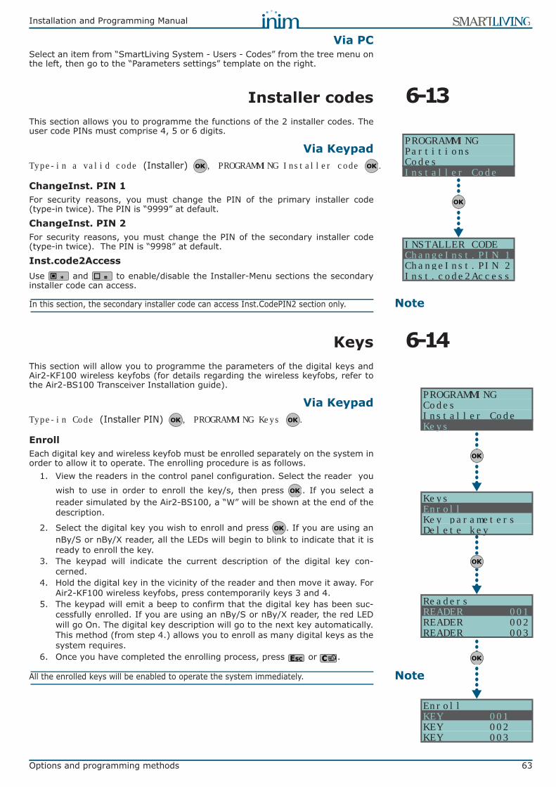
Installation and Programming Manual
Options and programming methods 63
Via PCSelect an item from “SmartLiving System - Users - Codes” from the tree menu onthe left, then go to the “Parameters settings” template on the right.
6-13Installer codesThis section allows you to programme the functions of the 2 installer codes. Theuser code PINs must comprise 4, 5 or 6 digits.
Via KeypadType-in a valid code (Installer) , PROGRAMMING Installer code .
ChangeInst. PIN 1For security reasons, you must change the PIN of the primary installer code(type-in twice). The PIN is “9999” at default.
ChangeInst. PIN 2For security reasons, you must change the PIN of the secondary installer code(type-in twice). The PIN is “9998” at default.
Inst.code2AccessUse and to enable/disable the Installer-Menu sections the secondaryinstaller code can access.
NoteIn this section, the secondary installer code can access Inst.CodePIN2 section only.
6-14KeysThis section will allow you to programme the parameters of the digital keys andAir2-KF100 wireless keyfobs (for details regarding the wireless keyfobs, refer tothe Air2-BS100 Transceiver Installation guide).
Via KeypadType-in Code (Installer PIN) , PROGRAMMING Keys .
EnrollEach digital key and wireless keyfob must be enrolled separately on the system inorder to allow it to operate. The enrolling procedure is as follows.
1. View the readers in the control panel configuration. Select the reader you
wish to use in order to enroll the key/s, then press . If you select areader simulated by the Air2-BS100, a “W” will be shown at the end of thedescription.
2. Select the digital key you wish to enroll and press . If you are using annBy/S or nBy/X reader, all the LEDs will begin to blink to indicate that it isready to enroll the key.
3. The keypad will indicate the current description of the digital key con-cerned.
4. Hold the digital key in the vicinity of the reader and then move it away. ForAir2-KF100 wireless keyfobs, press contemporarily keys 3 and 4.
5. The keypad will emit a beep to confirm that the digital key has been suc-cessfully enrolled. If you are using an nBy/S or nBy/X reader, the red LEDwill go On. The digital key description will go to the next key automatically.This method (from step 4.) allows you to enroll as many digital keys as thesystem requires.
6. Once you have completed the enrolling process, press or .
NoteAll the enrolled keys will be enabled to operate the system immediately.
PROGRAMMINGPartitionsCodesInstaller Code
INSTALLER CODEChangeInst.PIN 1ChangeInst.PIN 2Inst.code2Access
EnrollKEY 001KEY 002KEY 003
ReadersREADER 001READER 002READER 003
PROGRAMMINGCodesInstaller CodeKeys
KeysEnrollKey parametersDelete key
64 Options and programming methods
Installation and Programming Manual
Key parametersThis section allows you to programme all the parameters of the selected digital key.• Description - editable field for the name of the digital key user.• Partitions - the partitions the digital key is assigned to and therefore can
control.• Options - activated by means of keys and , are:
• Timers - this section allows you to associate a timer with the digital key. Thekey will be able to operate the system only when the associated timer is “On”.
• Shortcuts - this section allows you to programme up to 4 shortcuts (F1, F2,F3, F4) for each key.
The shortcut associated with the key can be one of the following types:•• None•• Arm/disarm•• Stop alarms•• Clear Call Queue•• Delete memory•• Activate Output•• Deactiv. outputs•• Overtime•• Teleservice req.•• Voice guide
If a digital key is held in the vicinity of an nBy/S or nBy/X reader, the LEDs willrun through a series of visual signals with the following meanings:
Delete keyThis section allows you to delete enrolled digital keys from the systemconfiguration. The enrolled digital keys can be found in the list with the symbol.
1. Use or to select the digital key you wish to delete. 2. Press to delete the selected digital key.
3. Press to confirm and exit.
Enable/disableThis section allows you to enable/disable the digital keys:
1. Use or to select the digital key you wish to enable/disable2. Use keys or to enable/disable the selected digital key.
3. Press to confirm and exit.
Via PCSelect an item from “SmartLiving System - Users - Digital keys” from the treemenu on the left, then go to the “Parameters settings” template on the right.
Option If enabled If disabled
Patrol The digital key will be able to disarm specific partitions for patrol purposes.
MaintenanceThe digital key will be able to block alarm/tamper
outputs for the time that it is held in front of a reader.
Use keyShortcutsIf a digital key is held in the vicinity of a reader, only the digital key shortcuts will be indicated,
and not the reader shortcuts.
If a digital key is held in the vicinity of a reader, only the reader shortcuts will be indicated and, if configured, the first shortcut programmed on the
digital key.
These options do not apply to Air2-KF100 wireless
keyfobs.DisarmNotAllowedIf a digital key is held in the vicinity of a reader
when partitions are armed, the Disarm option will be inhibited (all LEDs Off).
If a digital key is held in the vicinity of a reader when partitions are armed, the Disarm option will
be allowed (all LEDs Off).
LED indicator sequence Option: Use keyShortcutsenabled disabled
1 Red LED On Digital key shortcut F1 shortcut associated with the red LED on the reader
2 Blue LED On Digital key shortcut F2 shortcut associated with the blue LED on the reader
3 Green LED On Digital key shortcut F3 shortcut associated with the green LED on the reader
4 Yellow LED On Digital key shortcut F4 shortcut associated with the yellow LED on the reader
5 All LEDs On This sequence does not occur Digital key shortcut F1
6 All LEDs Off
Option: DisarmNotAllowedenabled disabled
No request to arm ALL the partitions common to both the key and reader.
Request to arm ALL the partitions common to both the key and reader.

Installation and Programming Manual
Options and programming methods 65
6-15Arming scenariosThis section allows you to configure up to different 30 arming scenarios.
Via Keypad1. Access “Arming scenarios” section.
Type-in Code (Installer) , PROGRAMMING Arming scenarios .
2. Use keys or to select the scenario then press .
DescriptionEditable field for the description of the scenario.
IconThis section allows you to select the icon you wish to assign to the scenario,simply by indicating the icon number (refer to Appendix B, Shortcuts at default):
1. Use keys or to scroll across the digits. 2. Use the number keys ( , etc.) to edit the number.
3. Press to confirm and exit.
The “Arm” shortcut associated with function key to will use (reveal)the icon selected in this section.
PartitionsThis section allows you to configure the scenarios of all the partitions managed bythe various models.
1. Use keys or to select the partition, then press .2. Use keys or to select the operating mode (Away, Stay, Disarm,
etc.).• None - the current operating mode of the partition will not be changed.• Away - the partition will arm in Away mode (interior and perimeter).• Stay - the partition will arm in Stay mode (perimeter only).• Instant - the partition will arm in Instant mode (perimeter only with zero
delay).• Disarm - the partition will disarm.OutputEach scenario, when applied, can activate one output (via keypad, at reader,over-the-phone, etc.). Use or to select the output then press .
NoteIt is possible to use a scenario to activate an output. This can be done through theScenarios section by simply leaving the respective “Partition” programming fields free(None), thus allowing the association of the Icons with the outputs.
3. Press to confirm and exit.
Via PCSelect an item from “SmartLiving System - Scenarios” from the tree menu on the left,then go to the “Parameters settings” template on the right.
6-16ShortcutsThis section allows you to create up to 36 different shortcuts.
Via Keypad1. Accessing the “Shortcuts” section:
Type-in Code (Installer PIN) , PROGRAMMING Shortcuts .
2. Use keys or to select the shortcut then press .
DescriptionThis is the editable label which identifies the shortcut.
SCENARIO 001DescriptionIconPartitions
PROGRAMMINGInstaller CodeKeysArming Scenarios
Arming ScenariosSCENARIO 001SCENARIO 002SCENARIO 003
PROGRAMMINGKeysArming ScenariosShortcuts
ShortcutsArm/DisarmStop alarmsClear Call Queue

66 Options and programming methods
Installation and Programming Manual
IconThis section allows you to select the icon you wish to represent the scenario,simply by indicating the icon number (refer to Appendix B, Shortcuts at default):
1. Use keys or to scroll across the digits. 2. Use the number keys ( , etc.) to edit the number.
3. Press to confirm and exit.
Via PCSelect an item from “SmartLiving System - Shortcut icons” from the tree menu on theleft, then go to the “Parameters settings” template on the right.
6-17ExpansionsThis section allows you to programme the parameters of the expansions.
Via KeypadType-in Code (Installer PIN) , PROGRAMMING Expansions .
Enable/disableThis section allows you to add/remove expansions from the I-BUS configuration,by means of keys and .
ChoosePeripheralThis section allows you to edit the description of each expansion board.
Via PC
6-18KeypadsThis section allows you to programme the parameters of the keypads.
Via KeypadType-in Code (Installer PIN) , PROGRAMMING Keypads .
Enable/disableThis section allows you to add/remove expansions from the I-BUS configuration,by means of keys and .
ChoosePeripheralThis section allows you to programme the various options of the selected keypad.• Description - editable field for the name of the digital key user.• Partitions - use and to enable/disable the keypad on the system
partitions.• Options:
•• Temperature off - if this option is enabled, the room temperature will beflashed in alternation on the display. This option applies to JOY/MAXkeypads only.
•• SilentExitTime - enable/disable the buzzer during partition Exit Time.•• SilentEntryTime - enable/disable the buzzer during entry partition Entry time•• SignalExitTime - enable/disable the buzzer when terminal T1 on the
keypad is activated as an output.• Func.KeyShortcuts - shortcuts assigned to keys , ..., . Function
keys F1 to F12 must be selected separately and programmed as follows:•• Type - this is the shortcut action which can be selected from those
available (refer to Appendix B, Shortcuts at default). It is necessary toprogramme an extra parameter for some shortcuts:- “Arm/disarm”, this parameter refers to one of the 30 scenarios
PROGRAMMINGArming ScenariosShortcutsExpansions
ExpansionsEnable/disableChoosePeripheralTable 37: Expansions - via SmartLeague software programme
Option Part of the system Template/sectionEnable/disable / Project
ChoosePeripheral Expansions - select the expansion Programming
KeypadsEnable/disableChoosePeripheral
PROGRAMMINGShortcutsExpansionsKeypads
KeypadsEnable/disableChoosePeripheral
KEYP. 001DescriptionPartitionsOptions
PROG. KEYPADSKEYP. 001KEYP. 002KEYP. 003
KeypadsEnable/disableChoosePeripheral
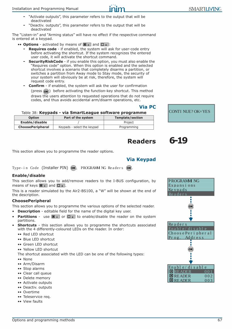
Installation and Programming Manual
Options and programming methods 67
- “Activate outputs”, this parameter refers to the output that will be deactivated
- “Deactiv. outputs”, this parameter refers to the output that will be deactivated
The “Listen-in” and “Arming status” will have no effect if the respective commandis entered at a keypad.
•• Options - activated by means of and :- Requires code - if enabled, the system will ask for user-code entry
before activating the shortcut. If the system recognizes the entered user code, it will activate the shortcut command.
- SecurityRiskCode - if you enable this option, you must also enable the “Requires code” option. When this option is enabled and the selected shortcut involves a scenario that completely disarms a partition, or switches a partition from Away mode to Stay mode, the security of your system will obviously be at risk, therefore, the system will request code entry.
- Confirm - if enabled, the system will ask the user for confirmation (press ) before activating the function-key shortcut. This method draws the users attention to requested operations that do not require codes, and thus avoids accidental arm/disarm operations, etc.
Via PC
6-19ReadersThis section allows you to programme the reader options.
Via KeypadType-in Code (Installer PIN) , PROGRAMMING Readers .
Enable/disableThis section allows you to add/remove readers to the I-BUS configuration, bymeans of keys and .This is a reader simulated by the Air2-BS100, a “W” will be shown at the end ofthe description.
ChoosePeripheralThis section allows you to programme the various options of the selected reader.• Description - editable field for the name of the digital key user.• Partitions - use or to enable/disable the reader on the system
partitions.• Shortcuts - this section allows you to programme the shortcuts associated
with the 4 differently-coloured LEDs on the reader. In order:•• Red LED shortcut•• Blue LED shortcut•• Green LED shortcut•• Yellow LED shortcutThe shortcut associated with the LED can be one of the following types:•• None•• Arm/Disarm•• Stop alarms•• Clear call queue•• Delete memory•• Activate outputs•• Deactiv. outputs•• Overtime•• Teleservice req.•• View faults
Table 38: Keypads - via SmartLeague software programmeOption Part of the system Template/section
Enable/disable / ProjectChoosePeripheral Keypads - select the keypad Programming
CONTINUE?OK=YES
Enable/disableREADER 001READER 002READER 003
PROGRAMMINGExpansionsKeypadsReaders
ReadersEnable/disableChoosePeripheralProg. Address
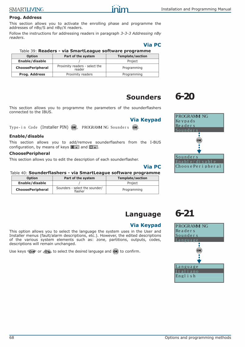
68 Options and programming methods
Installation and Programming Manual
Prog. AddressThis section allows you to activate the enrolling phase and programme theaddresses of nBy/S and nBy/X readers.Follow the instructions for addressing readers in paragraph 3-3-3 Addressing nByreaders.
Via PC
6-20SoundersThis section allows you to programme the parameters of the sounderflashersconnected to the IBUS.
Via KeypadType-in Code (Installer PIN) , PROGRAMMING Sounders .
Enable/disableThis section allows you to add/remove sounderflashers from the I-BUSconfiguration, by means of keys and .
ChoosePeripheralThis section allows you to edit the description of each sounderflasher.
Via PC
6-21LanguageVia Keypad
This option allows you to select the language the system uses in the User andInstaller menus (fault/alarm descriptions, etc.). However, the edited descriptionsof the various system elements such as: zone, partitions, outputs, codes,descriptions will remain unchanged.
Use keys or to select the desired language and to confirm.
Table 39: Readers - via SmartLeague software programmeOption Part of the system Template/section
Enable/disable / Project
ChoosePeripheral Proximity readers - select the reader Programming
Prog. Address Proximity readers Programming
PROGRAMMINGKeypadsReadersSounders
SoundersEnable/disableChoosePeripheral
Table 40: Sounderflashers - via SmartLeague software programmeOption Part of the system Template/section
Enable/disable / Project
ChoosePeripheral Sounders - select the sounder/flasher Programming
PROGRAMMINGReadersSoundersLanguage
LanguageItalianoEnglish

Installation and Programming Manual
Options and programming methods 69
6-22MessagesThis section allows you to record (and playback) all the voice messages. TheTable in the Appendix shows all the pre-recorded messages provided by theSmartLogos30M voice board.
Via Keypad1. Accessing the “Messages” section:
Type-in Code (Installer PIN) , PROGRAMMING Messages .
2. Use keys or to select the field you wish to change, then use thenumber keys ( , etc.) to edit the number.
orUse keys or to increase or decrease the number.
3. Press .4. Use or to select the instructions for the selected message then
press .
RecordBefore recording a voice message, you must first select:• No Message - no recording or playback• High quality - for superior recording/playback quality• Average quality - for good recording/playback quality (similar to phone-line
quality).High quality messages occupy twice the memory space of average qualitymessages of the same length.
The recording will start when is pressed, the running recording time(seconds) will be indicated by a second-counter on the keypad display. If youwish to interrupt the record/playback operation manually press , otherwise, itwill end automatically when the pre-set time-out expires.
PlayMessage playback section. You can adjust the volume during the playback phaseusing keys and .
DeleteDelete message section. The control panel will ask for confirmation beforedeleting the message, by means of the ( ) key.
Via PCThe Parameters settings template of the “SmartLiving System - Announcements” willallow you to:• upload all the voice messages• download all the voice messages• format voice boardSelect an item from “SmartLiving System - Announcements” from the tree menuon the left, then go to the “Parameters settings” template on the right andprogramme the selected message.
6-23Default settingsThis section allows you to reset to default settings all the control panelparameters, auto-learn zone balancing values, auto-enroll I-BUS peripherals andrestore the event codes of CONTACT-ID reporting format.Reset to default can be carried out at a keypad via the installer menu (detailsfollow), or via the control panel motherboard, using the following procedure.
1. Disconnect all power to the control panel (Mains and and battery power).2. Short-circuit terminals “2” and “3” of the serial cable connector (refer to
Table 4: Control panels - description of parts, S).3. Power-up the control panel and maintain the short-circuit condition on ter-
minals “2” and “3” for at least 5 seconds.
CODINGEmpty messageHigh qualityAverage quality
MessagesRecordPlayDelete
PROGRAMMINGSoundersLanguageMessages
Messages_01 Messages(Min. 00)(Min. 485)
Record
0034 sec.
Serial port
Terminals to be short-circuited2
3
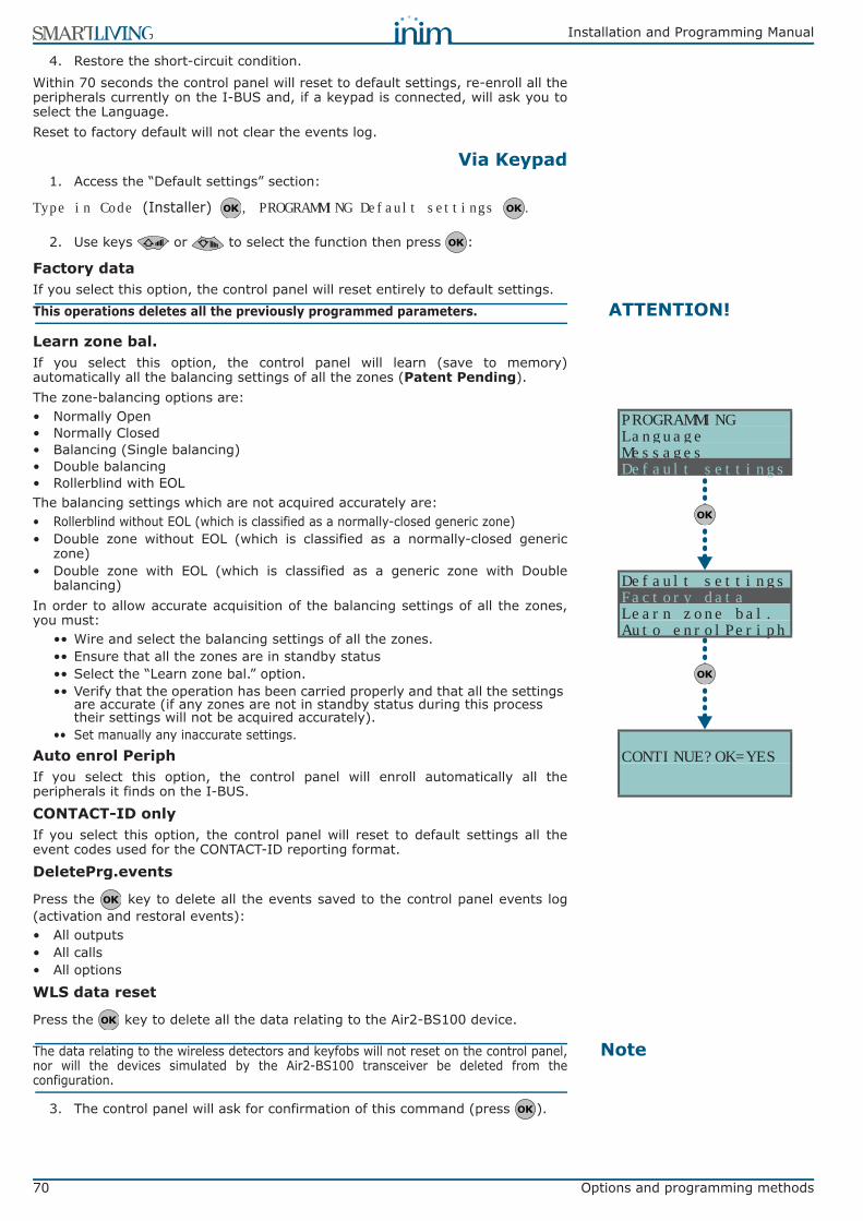
70 Options and programming methods
Installation and Programming Manual
4. Restore the short-circuit condition.Within 70 seconds the control panel will reset to default settings, re-enroll all theperipherals currently on the I-BUS and, if a keypad is connected, will ask you toselect the Language.Reset to factory default will not clear the events log.
Via Keypad1. Access the “Default settings” section:
Type in Code (Installer) , PROGRAMMING Default settings .
2. Use keys or to select the function then press :
Factory dataIf you select this option, the control panel will reset entirely to default settings.
ATTENTION!This operations deletes all the previously programmed parameters.
Learn zone bal.If you select this option, the control panel will learn (save to memory)automatically all the balancing settings of all the zones (Patent Pending).The zone-balancing options are:• Normally Open• Normally Closed• Balancing (Single balancing)• Double balancing• Rollerblind with EOLThe balancing settings which are not acquired accurately are:• Rollerblind without EOL (which is classified as a normally-closed generic zone)• Double zone without EOL (which is classified as a normally-closed generic
zone)• Double zone with EOL (which is classified as a generic zone with Double
balancing)In order to allow accurate acquisition of the balancing settings of all the zones,you must:
•• Wire and select the balancing settings of all the zones.•• Ensure that all the zones are in standby status•• Select the “Learn zone bal.” option. •• Verify that the operation has been carried properly and that all the settings
are accurate (if any zones are not in standby status during this process their settings will not be acquired accurately).
•• Set manually any inaccurate settings.Auto enrol PeriphIf you select this option, the control panel will enroll automatically all theperipherals it finds on the I-BUS.
CONTACT-ID onlyIf you select this option, the control panel will reset to default settings all theevent codes used for the CONTACT-ID reporting format.
DeletePrg.events
Press the key to delete all the events saved to the control panel events log(activation and restoral events):• All outputs• All calls• All options
WLS data reset
Press the key to delete all the data relating to the Air2-BS100 device.
NoteThe data relating to the wireless detectors and keyfobs will not reset on the control panel,nor will the devices simulated by the Air2-BS100 transceiver be deleted from theconfiguration.
3. The control panel will ask for confirmation of this command (press ).
CONTINUE?OK=YES
PROGRAMMINGLanguageMessagesDefault settings
Default settingsFactory dataLearn zone bal.Auto enrolPeriph
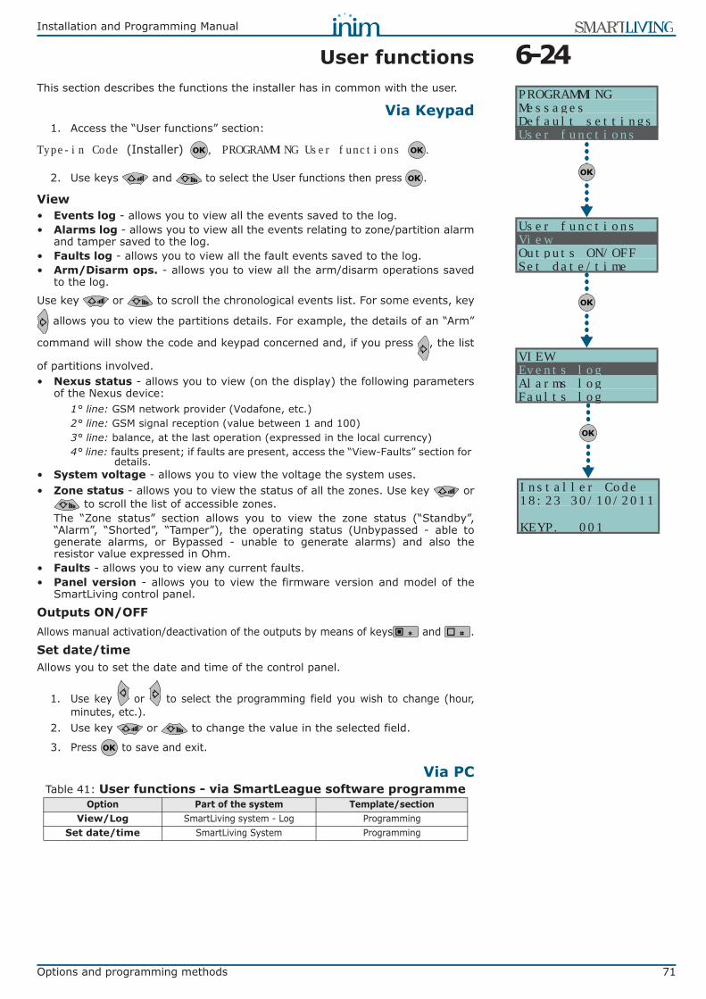
Installation and Programming Manual
Options and programming methods 71
6-24User functionsThis section describes the functions the installer has in common with the user.
Via Keypad1. Access the “User functions” section:
Type-in Code (Installer) , PROGRAMMING User functions .
2. Use keys and to select the User functions then press .
View• Events log - allows you to view all the events saved to the log.• Alarms log - allows you to view all the events relating to zone/partition alarm
and tamper saved to the log.• Faults log - allows you to view all the fault events saved to the log.• Arm/Disarm ops. - allows you to view all the arm/disarm operations saved
to the log.
Use key or to scroll the chronological events list. For some events, key
allows you to view the partitions details. For example, the details of an “Arm”
command will show the code and keypad concerned and, if you press , the list
of partitions involved.• Nexus status - allows you to view (on the display) the following parameters
of the Nexus device:1° line: GSM network provider (Vodafone, etc.)2° line: GSM signal reception (value between 1 and 100)3° line: balance, at the last operation (expressed in the local currency)4° line: faults present; if faults are present, access the “View-Faults” section for
details.• System voltage - allows you to view the voltage the system uses.• Zone status - allows you to view the status of all the zones. Use key or
to scroll the list of accessible zones.The “Zone status” section allows you to view the zone status (“Standby”,“Alarm”, “Shorted”, “Tamper”), the operating status (Unbypassed - able togenerate alarms, or Bypassed - unable to generate alarms) and also theresistor value expressed in Ohm.
• Faults - allows you to view any current faults.• Panel version - allows you to view the firmware version and model of the
SmartLiving control panel.
Outputs ON/OFF Allows manual activation/deactivation of the outputs by means of keys and .
Set date/timeAllows you to set the date and time of the control panel.
1. Use key or to select the programming field you wish to change (hour,minutes, etc.).
2. Use key or to change the value in the selected field.
3. Press to save and exit.
Via PC
Installer Code18:23 30/10/2011
KEYP. 001
VIEWEvents logAlarms logFaults log
PROGRAMMINGMessagesDefault settingsUser functions
User functionsViewOutputs ON/OFF Set date/time
Table 41: User functions - via SmartLeague software programmeOption Part of the system Template/section
View/Log SmartLiving system - Log ProgrammingSet date/time SmartLiving System Programming
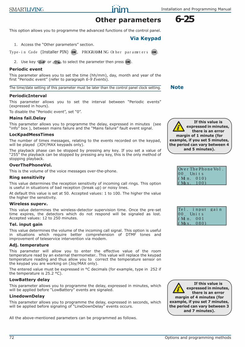
72 Options and programming methods
Installation and Programming Manual
6-25Other parametersThis option allows you to programme the advanced functions of the control panel.
Via Keypad1. Access the “Other parameters” section.
Type-in Code (Installer PIN) , PROGRAMMING Other parameters .
2. Use key or to select the parameter then press .
Periodic eventThis parameter allows you to set the time (hh/mm), day, month and year of thefirst “Periodic event” (refer to paragraph 6-9 Events).
NoteThe time/date setting of this parameter must be later than the control panel clock setting.
PeriodicIntervalThis parameter allows you to set the interval between “Periodic events”(expressed in hours).To disable the “Periodic event”, set “0”.
Mains fail.DelayThis parameter allows you to programme the delay, expressed in minutes (see“info” box ), between mains failure and the “Mains failure” fault event signal.
LocKpadMessTimesThe number of times messages, relating to the events recorded on the keypad,will be played (JOY/MAX keypads only).The playback phase can be stopped by pressing any key. If you set a value of“255” the playback can be stopped by pressing any key, this is the only method ofstopping playback.
OverThePhoneVol.This is the volume of the voice messages over-the-phone.
Ring sensitivityThis value determines the reception sensitivity of incoming call rings. This optionis useful in situations of bad reception (break up) or noisy lines.At default this value is set at 50. Accepted values: 1 to 100. The higher the valuethe higher the sensitivity.
Wireless superv.This value determines the wireless-detector supervision time. Once the pre-settime expires, the detectors which do not respond will be signaled as lost.Accepted values: 12 to 250 minutes.
Tel. input gainThis value determines the volume of the incoming call signal. This option is usefulin situations which require better comprehension of DTMF tones andimprovement of teleservice intervention via modem.
Adj. temperatureThis parameter will allow you to enter the effective value of the roomtemperature read by an external thermometer.. This value will replace the keypadtemperature reading and thus allow you to correct the temperature sensor onthe keypad you are working on (Joy/MAX only).The entered value must be expressed in °C decimals (for example, type in 252 ifthe temperature is 25.2 °C).
LowBattery delayThis parameter allows you to programme the delay, expressed in minutes, whichwill be applied before “LowBattery” events are signaled.
LinedownDelayThis parameter allows you to programme the delay, expressed in seconds, whichwill be applied before signaling of “LineDownDelay” events occurs.
All the above-mentioned parameters can be programmed as follows.
If this value is expressed in minutes,
there is an error margin of 1 minute (for
example, if you set 5 minutes, the period can vary between 4
and 5 minutes).
OverThePhoneVol.00_ Units(Min. 010)(Max. 100)
Tel. input gain00_ Units(Min. 001(Max. 080)
If this value is expressed in minutes,
there is an error margin of 4 minutes (for
example, if you set 7 minutes, the period can vary between 3
and 7 minutes).
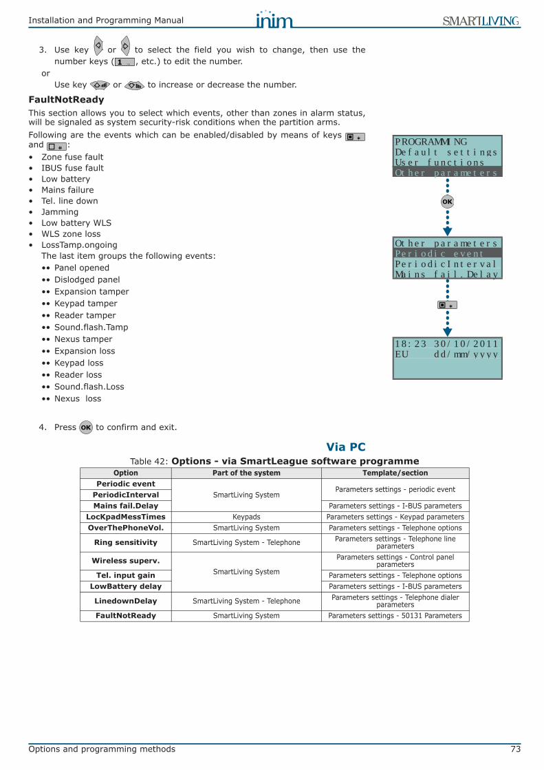
Installation and Programming Manual
Options and programming methods 73
3. Use key or to select the field you wish to change, then use thenumber keys ( , etc.) to edit the number.
orUse key or to increase or decrease the number.
FaultNotReadyThis section allows you to select which events, other than zones in alarm status,will be signaled as system security-risk conditions when the partition arms.Following are the events which can be enabled/disabled by means of keys and :• Zone fuse fault• IBUS fuse fault• Low battery• Mains failure• Tel. line down• Jamming• Low battery WLS• WLS zone loss• LossTamp.ongoing
The last item groups the following events:•• Panel opened•• Dislodged panel•• Expansion tamper•• Keypad tamper•• Reader tamper•• Sound.flash.Tamp•• Nexus tamper•• Expansion loss•• Keypad loss•• Reader loss•• Sound.flash.Loss•• Nexus loss
4. Press to confirm and exit.
Via PC
18:23 30/10/2011EU dd/mm/yyyy
PROGRAMMINGDefault settingsUser functionsOther parameters
Other parametersPeriodic eventPeriodicIntervalMains fail.Delay
Table 42: Options - via SmartLeague software programmeOption Part of the system Template/section
Periodic eventSmartLiving System
Parameters settings - periodic eventPeriodicIntervalMains fail.Delay Parameters settings - I-BUS parameters
LocKpadMessTimes Keypads Parameters settings - Keypad parametersOverThePhoneVol. SmartLiving System Parameters settings - Telephone options
Ring sensitivity SmartLiving System - Telephone Parameters settings - Telephone line parameters
Wireless superv.SmartLiving System
Parameters settings - Control panel parameters
Tel. input gain Parameters settings - Telephone optionsLowBattery delay Parameters settings - I-BUS parameters
LinedownDelay SmartLiving System - Telephone Parameters settings - Telephone dialer parameters
FaultNotReady SmartLiving System Parameters settings - 50131 Parameters

74 Options and programming methods
Installation and Programming Manual
6-25-1Telephone line adjustmentThe “OverThePhoneVol.” and “Tel. input gain” parameters can be used to correctthe voice functions of the dialer and the DTMF tones. The values of theseparameters affect each other, therefore, and a good result is always acompromise.If you are not using a GSM interface, you should:• Adjust one parameter at a time and carry out tests to verify the result.• Increase/decrease the values in small steps (for example, from 25 to 22 and
not from 25 to 15).• If the DTMF tones are not recognized, or are recognized with difficulty, decrease the
value of the “Volume Tel.voice” parameter (in small steps of 2 or 3 units) and verifythe effect. If there is no improvement, increase the value of the “VolumeTel. In.”parameter until an acceptable combination is achieved.Do not increase the “VolumeTel. In” parameter excessively, as an excessivevalue may cause incorrect interpretation of DTMF tones.
• If the volume of the telephone messages is low, increase the “VolumeTel.voice” (in small steps of 1 or 2 units) and verify the effect. An excessivevalue of the “Volume Tel.voice.” parameter may cause incorrect interpretationof DTMF tones.
In most cases, the value of the “Volume Tel.voice” parameter is between 15 and25, whereas, the value of the “VolumeTel. In.” parameter is between 20 and 30.If you are not using a SmartLink GSM interface, you should:• If the DTMF tones are not recognized, or are recognized with difficulty,
increase the value of the SmartLINK “VolumeTel.In” parameter by 1 or 2notches over the medium value “M” then verify the effect. If there is noimprovement, decrease the value of the “VolumeTel.In.” parameter of theSmartLiving control panel until an acceptable combination is achieved..
NoteAny changes to the value of the SmartLink “VolumeTel.In.” parameter come into effectalmost 2 minutes after the setting change, therefore, you must allow this time to passbefore verifying the effect.
6-26Programming the NexusThe Nexus programming phase allows you to select which actions the controlpanel will implement on receiving a voice call/SMS message (from an authorizeduser) over the GSM network. Each command comprises a group of fully-programmable parameters.Each time a user requests an operation - via a correctly formatted SMS messageor voice call to the SIM card of the Nexus - the control panel will activate therespective shortcut/event and send confirmation (feedback) of the successfullyimplemented command.The following parameters can be programmed solely via the SmartLeaguesoftware programme. Select the “Nexus” item from the SmartLiving systemlayout (on the left) and then go to the “Programming” section on the right toprogramme the relative parameters.
6-26-1SMS CommandsThe “Programming - SMS Commands" section allows you to programme up to 30SMS-activated commands.
PANEL OPTIONS• Action - this identifies the number of the command in the table displayed.• SMS Text - this is an identification string for SMS message command.• Shortcut - this field will allow you to select one of the following shortcuts:
•• Arm/Disarm•• Stop alarms•• Clear call queue•• Delete memory•• Activate outputs•• Deactiv. outputs•• Balance enquiry - this command (which is not a control-panel shortcut
command) generates a balance enquiry relating to the SIM inside the Nexus (refer to paragraph 6-26-3 General parameters)
•• Status - this command (which is not a control-panel shortcut command) generates a status enquiry relating to the Nexus (refer to paragraph 6-26-3 General parameters)

Installation and Programming Manual
Options and programming methods 75
•• Inhibit (bypass) control panel zones•• Activate (unbypass) control panel zones
• Shortcut option - field for the selection of the parameter relating to theshortcut.
• Shortcut 2 - field for the selection of a second shortcut which is to beactivated the one selected previously (as above).
• Shortcut option 2 - as per “Shortcut option” but applies to “Shortcut 2”.• Feedback - identifies the type of command feedback.
•• SMS - feedback will be provided by an SMS text to the telephone number of the caller (command dispatcher).Positive outcome: <SMS Text>: “done”Negative outcome: <SMS Text>: “failed”<Cause><Cause> is the explanation of failure to carry out the command.••• “Invalid code”••• “Invalid terminal”••• “Terminal already in the requested status”••• “Code not enabled”••• “Zone not ready”••• “Unbypassable zone”
•• Ring - feedback is provided on the telephone of the caller (command dispatcher). Positive outcome is indicated by a “ring”; negative outcome is indicated by no “ring”.
NoteBoth SMS and Ring feedback occur only when the caller's telephone number is available(caller number not hidden).
•• Buzzer - feedback is provided by an audible signal on the Nexus buzzer. Positive outcome is indicated by a three short audible signals; negative outcome is indicated by five long audible signals.
COMMAND USING SMS TEXT
Users who wish to activate a command via SMS text must enter the commanddetails as follows:
<xxxxxx> <SMS Text>where:• <xxxxxx> stands for the user-access PIN• a blank space must be keyed in after PIN entry• <SMS Text> which is the command identifier, as previously described
EXAMPLEYou wish the control panel to activate “Scenario 3”, switch On the perimeter lightsand confirm the operation via SMS text. For an operation of this type, proceed asfollows:
1. “SMS Text” - choose the desired description, for example “Night mode”2. “Shortcut” - select the “Arm/Disarm” shortcut3. “Shortcut option”: “Scenario 3”4. “Shortcut 2” - select the “Activate outputs” shortcut5. “Shortcut option 2” - the output associated with the perimeter lights6. “Confirm” - SMS
When a user keys in the following SMS text on a mobile (cellular) phone:123456 Night mode
where “123456” stands for the User's access PIN and this message is sent to thenumber of the SIM card of the Nexus, the control panel will carry out therequested operations and will send confirmation to the mobile phone of the callerwho dispatched the command.
DEFAULT COMMANDSThe installer by modify the five predefined default commands:• “CREDIT” for balance enquiries relating to the SIM card of the Nexus - the
user will receive an SMS text indicating the remaining credit.• “STATUS” for status enquiries relating to the Nexus - the user will receive an
SMS text indicating the:•• device name and firmware revision•• GSM network provider•• GSM signal reception level•• device tamper status•• BUS status•• Balance (remaining credit)
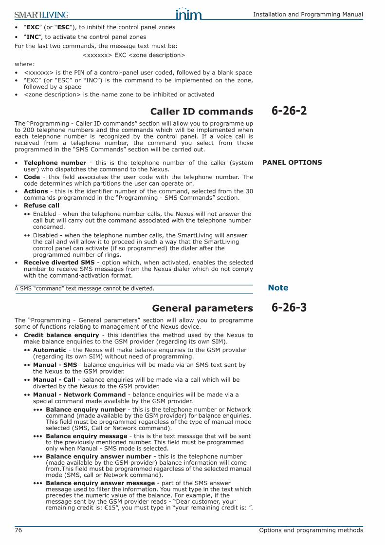
76 Options and programming methods
Installation and Programming Manual
• “EXC” (or “ESC”), to inhibit the control panel zones• “INC”, to activate the control panel zonesFor the last two commands, the message text must be:
<xxxxxx> EXC <zone description>where:• <xxxxxx> is the PIN of a control-panel user coded, followed by a blank space• “EXC” (or “ESC” or “INC”) is the command to be implemented on the zone,
followed by a space• <zone description> is the name zone to be inhibited or activated
6-26-2Caller ID commandsThe “Programming - Caller ID commands” section will allow you to programme upto 200 telephone numbers and the commands which will be implemented wheneach telephone number is recognized by the control panel. If a voice call isreceived from a telephone number, the command you select from thoseprogrammed in the “SMS Commands” section will be carried out.
PANEL OPTIONS• Telephone number - this is the telephone number of the caller (systemuser) who dispatches the command to the Nexus.
• Code - this field associates the user code with the telephone number. Thecode determines which partitions the user can operate on.
• Actions - this is the identifier number of the command, selected from the 30commands programmed in the “Programming - SMS Commands” section.
• Refuse call •• Enabled - when the telephone number calls, the Nexus will not answer the
call but will carry out the command associated with the telephone number concerned.
•• Disabled - when the telephone number calls, the SmartLiving will answer the call and will allow it to proceed in such a way that the SmartLiving control panel can activate (if so programmed) the dialer after the programmed number of rings.
• Receive diverted SMS - option which, when activated, enables the selectednumber to receive SMS messages from the Nexus dialer which do not complywith the command-activation format.
NoteA SMS “command” text message cannot be diverted.
6-26-3General parametersThe “Programming - General parameters” section will allow you to programmesome of functions relating to management of the Nexus device.• Credit balance enquiry - this identifies the method used by the Nexus to
make balance enquiries to the GSM provider (regarding its own SIM).•• Automatic - the Nexus will make balance enquiries to the GSM provider
(regarding its own SIM) without need of programming.•• Manual - SMS - balance enquiries will be made via an SMS text sent by
the Nexus to the GSM provider.•• Manual - Call - balance enquiries will be made via a call which will be
diverted by the Nexus to the GSM provider.•• Manual - Network Command - balance enquiries will be made via a
special command made available by the GSM provider.••• Balance enquiry number - this is the telephone number or Network
command (made available by the GSM provider) for balance enquiries. This field must be programmed regardless of the type of manual mode selected (SMS, Call or Network command).
••• Balance enquiry message - this is the text message that will be sent to the previously mentioned number. This field must be programmed only when Manual - SMS mode is selected.
••• Balance enquiry answer number - this is the telephone number (made available by the GSM provider) balance information will come from.This field must be programmed regardless of the selected manual mode (SMS, call or Network command).
••• Balance enquiry answer message - part of the SMS answer message used to filter the information. You must type in the text which precedes the numeric value of the balance. For example, if the message sent by the GSM provider reads - “Dear customer, your remaining credit is: €15”, you must type in “your remaining credit is: ”.

Installation and Programming Manual
Options and programming methods 77
•• Low credit threshold - remaining credit limit, expressed in local currency. If credit drops below this limit, the Nexus dialer will signal “Low credit”.
•• Credit enquiry interval - interval, expressed in hours, which must pass between one automatic balance-enquiry and another.
NoteIf the GSM provider in question is non standard, or has modified the standard credit-notification process, you must use the manual credit-enquiry method.
• Input volume - this option allows you to adjust the volume of the inputsignal to the Nexus and thus the volume of the incoming signal to the controlpanel.
• Output volume - this option allows you to adjust the volume of the outputsignal from the Nexus to recipient telephone devices.
• Volume adjust - this option allows to balance the ratio between input andoutput volumes.
• Disable tamper - this option, if enabled, deactivates tamper signalling fromthe Nexus dialer.
• Delay for Emergency signal (sec) - interval, expressed in seconds, whichthe Nexus dialer allows to pass before automatically generating the signalsprogrammed for the “Nexus loss” event.
6-26-4Text for SMS messagesThe “Parameters settings - Customizable SMS Messages” section will allow you tocreate up to 50 SMS text messages of 80 alphanumeric characters each. Thesemessages can be associated with the events by means of the “SMS messagenumber/index” option described in paragraph 6-9 Events.

78 Errors and faults
Installation and Programming Manual
Chapter 7
ERRORS ANDFAULTS
7-1Faults detected by the controlpanel
The following table shows the system faults which are signaled on the yellow LEDon the keypad :
FAULT Message on the User menu, “View/Faults” Probable cause Note
Zone fuse blown Zone fuse fault Excessive current draw on the “+AUX” terminals of the control panel
BUS fuse blown IBUS fuse fault Excessive current draw on the “+” terminal of the control panel
Backup battery inefficient or not
connectedLow battery The backup battery of the control panel is almost
empty or disconnected.
Primary power-source loss Mains failure The primary power source voltage (230 Vac) has
failed or has been disconnected
The PSTN landline is unavailable Tel. line down Trouble on the PSTN landline
Interference Jamming Wireless transmission is poor
Wireless detector battery low Low battery WLS
The battery of at least one wireless detector is running out
To view “LowBatt. WLS” and “LostWLSzone” events, access the “View/Faults” section of
the User menu, then press to view the list of devices
involved in the fault event.Wireless detector not
operative WLS zone loss At least one wireless detector is not operating
Nexus GSM dialer faults
GSM fault / Low signal
The GSM network signal is insufficient
Press on “Nexus Fault” to access the list of current faults.
GSM fault / GSM module fault
The GSM module of the Nexus dialer is not operating properly. Call your installer company.
GSM fault / SIM commun.fault
The SIM card does not respond or is not present.The SIM card PIN is not disabled.
Nexus Fault / Low Credit
The credit left on the SIM card is below the minimum credit threshold.
GSM fault / Provider missing
The GSM network provider of the SIM in use is unavailable.
Device loss or tamper in progress LossTamp.ongoing
One of the following events has occurred:• Panel opened• Dislodged panel• Expansion tamper• Keypad tamper• Reader tamper• Sound.flash.Tamp• Expansion loss• Keypad loss• Reader loss• Sound.flash.Loss

Installation and Programming Manual
Errors and faults 79
7-2Communication BUS (I-BUS)The control panel monitors the I-BUS continuously.If no signals (control panel and peripheral signals) are detected on the I-BUS forover 40 seconds, the keypad displays will show the warning opposite. The displaywill show the:
1. Keypad model 2. Keypad firmware version3. Error type4. Keypad address and built-in reader address (Joy/MAX only)
First check that cable “D” of the I-BUS is connected properly. Then check theproper operating capacity of the I-BUS and the general integrity of the entiresystem.If the message opposite appears on the keypad display, it means that I-BUS isoperating properly but cannot communicate with the keypad in question.Therefore, the keypad is not present in the system configuration.
NoteOne of the two messages shown in the figures may also appear during the control panelfirmware updates.
7-3LED activityThe blue and yellow LEDs on the control panel motherboard (refer to Table 4:Control panels - description of parts, X) may help in providing informationregarding the proper operating capacity of the control panel firmware and I-BUS,as follows.
Blue LEDIf the control panel is operating properly, the blue LED on the motherboard willblink rapidly. However, at the end of a programming session via keypad or PC, orduring restoral of default settings or re-programming operations, the LED may beeither On solid or Off. It will blink rapidly once the operation is completed.If the LED is On or Off permanently for no apparent reason (see above), it meansthat all the system functions are blocked.Shut the system down and contact your dealer immediately.
Yellow LEDIf the control panel is operating properly, the yellow LED on the motherboardshould flicker. However, at the end of a programming session via keypad or PC, orduring restoral of default settings or re-programming operations, the LED may beeither On solid or Off. It will blink rapidly once the operation is completed.If the yellow LED is On or Off permanently, it means that there is trouble on the I-BUS.If the LED is On or Off permanently for no apparent reason (see above), it meansthat the I-BUS is blocked. This condition is confirmed by the loss ofcommunication with the keypads, readers and expansions.Check the integrity of the I-BUS line.
Faults on IVY-BUS sounderflasher
Sounder faults / Horn fault
A defect/damage has been detected on the horn/sounder.
Press on “Sounder faults” to access the list of devices which have at least one fault present.
Press on the selected sounderflasher to access the list of current faults on the device
concerned.
Sounderflasher faults / LowBatt.Soundfl.
A low-voltage value has been detected on the sounderflasher battery.
If the voltage drops below 10V, the device will inhibit the sounder and activate only the flasher (in the event of an alarm). If the voltage drops below 8V, the device will inhibit both the sounder
and the flasher.
Sounderflasher Faults / Battery resist.
An excessive internal resistance has been detected on the sounderflasher battery. This type
of deep fault indicates corrosion inside the battery, therefore, the battery must be replaced.
Violation of zones with faults Faults on zones Violation has occurred on one or more zones with
the “Fault zone” option enabled.Press to access the list of
zones involved.
- JOY/MAX -FW RELEASE 1.00NO COMMUNICATIONK01 P14
- JOY/MAX -FW RELEASE 1.00NOT ENROLLEDK01 P14

80 Errors and faults
Installation and Programming Manual
7-4Ring SensitivityThe various configurations of modern telephone lines and the multiplicity ofsignals that transit along them, require major attention in the design of phone-line interfaces. The optimized phone-line interface on-board SmartLiving controlpanels has been especially designed to satisfy present day requirements. Inaddition to the traditional telephone plug for land line (PSTN) connections, thereare usually boards for ISDN or ADSL connections.If there are ADSL filters on the line, it will be necessary to connect the controlpanel downstream of the filters, to the line dedicated to telephone equipment(this line is clearly indicated on the filters).Following are two “trouble” conditions which may be caused by ISDN or ADSLconnections, etc. , and the “actions” you must take if you encounter suchproblems.• Problem - The control panel is enabled for “Answerphone” and “Teleservice”
functions but fails to pick up incoming calls after the programmed number ofrings or picks up after more rings than programmed. Answer - Increase thevalue of the “Ring Sensitivity” parameter to a suitable level.
• Problem - The control panel is enabled for “Answerphone” and “Teleservice”functions but picks up during “through” calls (calls that should not involve thecontrol panel). Answer - Decrease the value of the “Ring Sensitivity”parameter to a suitable level.

Installation and Programming Manual
Technical terminology and Glossary 81
Appendix A
TECHNICAL TERMINOLOGYAND GLOSSARY
Violation of a zone with this attribute will generate an instant alarm even when the partitions itbelongs to are disabled. The system will generate the respective alarms which will be shown onthe keypad.These zones usually monitor conditions that are not directly connected to intrusion control. Forexample, Water tank overflow and flooding detectors are usually configured as 24H zones.If you are installing a fire detector, please remember that the inputs of SmartLiving controlpanels are not compliant with EN 50131-1 and EN 50131-3.
24 HOUR ZONE
These are 4, 5 or 6 digit PINs which allow the building occupants (users) to access the system.Each code can be programmed to control specific functions only, and to operate the system tosuit the requirements of the Main user.Code types• Installer code:used by the installer company technician• User code:assigned to the building occupants
ACCESS CODES
Detection of non-authorized entry into the protected building. More specifically, activation ofalarm signaling devices (detectors).
ALARM
A parameter generally associated with zones. This value determines the number of alarm eventsa zone can generate before the partitions it belongs to disarm. This value (number of alarmevents) resets to zero when the zone partitions re-arm or reset.If a zone is allowed to generate an unlimited number of alarm events, it is classified as a“repetitive” zone.
ALARM CYCLES
In the event of:• Zone Alarm• terminal tamper• open panel or dislodged panel• peripheral tamper (keypads, expansions, readers)• peripheral loss (keypads, expansions, readers)• false keyThe red LEDs on the system keypads and readers go On each time one of the previously-mentioned events occur. This visual warning signal is held even after the event ends (alarmmemory), in order to warn you that an event occurred during your absence. This visual warningsignal will be held until you clear the event memory (refer to Delete Memory).
ALARM OR TAMPER MEMORY
This is a private company that monitors premises protected by intrusion control systemsequipped with Digital or Voice dialers (refer to Digital dialer and Voice dialer).Alarm Receiving Centres receive alarm reports from monitored systems and take all thenecessary actions to protect the occupants of the protected premises.
ALARM RECEIVING CENTRE (ARC)
The “Answerphone” function, if enabled by the user, allows the control panel to answer incomingcalls after a pre-set number of rings. The control panel will pick-up and play the recordedanswer message.During the call, the recipient can type-in a valid PIN (enabled for over-the-phone control) andaccess the authorized functions.
ANSWERPHONE
User operations on one or more partitions. These generally indicate also the status of thepartitions. Under normal circumstances, the zones of armed partitions can generate alarms.Under normal circumstances, the zones of disarmed partitions cannot generate alarms. Thesystem generates tamper alarms even when partitions are disarmed.
ARM/DISARM
You can enable/disable the Auto-arm function on each separate partition.If the auto-arm option is enabled on a timer-controlled partition, the partition will arm/disarm inaccordance with the ON/OFF settings of the timer.
AUTO-ARM
A zone with this attribute will be bypassed automatically by the control panel, if the partition itbelongs to arms when the zone is not in standby status.The zone will be unbypassed automatically when it restores to standby or when the partition itbelongs to is disarms.
AUTO-BYPASSABLE ZONES
These zones operate in the same way as 24h zones, but do not generate partition alarms orvisual signals on the system reader and keypad LEDs.Zones configured in this way can be used for automation applications.
AUTOMATION ZONE
82 Technical terminology and Glossary
Installation and Programming Manual
This is the secondary power source of the system. If primary (230 Vac) power failure occurs, thebattery will take over.SmartLiving control panels use sealed lead batteries. The battery housing determines themaximum size of the battery and therefore, its power-storage capacity. SmartLiving controlpanels provide housing for one battery @12V 7Ah. The control panel monitors the batterycontinuously and keeps it is under constant charge (from Mains).
BACKUP BATTERY
Connection of a zone to a terminal configured as an input.It is necessary to programme the balancing of each separate zone and wire the terminalaccordingly. The SmartLiving intrusion control panel provides 6 different types of balancing, asfollows:• Normally Open• Normally Closed• EOL• DEOL• Double zones (only terminals with DOUBLING configuration)• Double zones with EOL (only for terminals with DOUBLING configuration)DEOL and customized zones can discriminate 4 conditions:• Short-circuit• standby• alarm• tamperIf you observe the Events list, you will see that there is an alarm event for each zone and atamper event for each terminal. This is because a terminal configured as a double zone (ordouble zone with EOL) must be able to discriminate between alarm and standby conditions oneach single zone, whereas tamper and short-circuit conditions involve the entire terminal andnot the single zone.
BALANCING
An output, that once activated, requires an explicit command to deactivate it.Generally, bistable outputs are used to provide immediate signaling (in real-time) of specificevents that occur on the system. For example, if the “Mains Failure” event is associated with abistable output that is connected to a LED, the LED will signal the event immediately.
BISTABLE OUTPUT
A bypassed (disabled) zone cannot generate alarms. Each zone can be bypassed/unbypassedmanually by the system users, or automatically by the control panel. Automatic bypassoperations can take place only when the zone is configured as “Auto-bypassable” and theconditions that regulate auto-bypass operations are in effect (refer to Zone Attributes – Auto-bypassable).Zone deactivation is useful when detectors are not working properly and you wish to avoid falsealarms. Under normal circumstances, bypassed (disabled) zones can still generate tamperevents. If you do not wish this to occur you must set the "Bypass Tamper" option on the controlpanel.
BYPASS - ZONE DEACTIVATION
A list of outgoing event-associated calls the control panel must send to programmed contactnumbers.Enabled users can clear the call queue manually.
CALL QUEUE
A zone with this attribute will generate “Chime on partition” events, if violated when thepartitions it belongs to are disarmed.Keypads which have partitions in common with the chime zone will emit an audible signal whenthe “Chime on partition” event occurs. If all the partitions the zone belongs to are armed, thezone will operate as programmed. This function is widely used in commercial buildings (shops,etc.), and is generally associated with the zone that monitors the entrance to the premises inorder to signal the arrival of customers.
CHIME ZONE
Activation of a zone with this configuration generates the command it is assigned to.SmartLiving control panels manage the following commands:• Disarm zone: if activated, it will disarm all the partitions it belongs to. Zones configured in
this way can be used to disarm partitions by means of a keyswitch.• Arm zone: if activated, it will arm all the partitions it belongs to. For example, keyswitches
are usually configured as command zones.• OnArm/OffDisarm zone: if activated, it will generate an arm-partitions command and, the
instant it restores to standby, a disarm-partitions command. The command will affect onlythe partitions the zone belongs to. Zones configured in this way can be used to arm/disarmpartitions by means of a keyswitch.
• Switch zone: if activated when all the partitions it belongs to are disarmed, it will arm allthe partitions. If activated when even one of the partitions it belongs to is armed, it willdisarm all of its partitions. The command will affect only the partitions the zone belongs to.Zones configured in this way can be used to arm/disarm partitions by means of a keyswitch.
• Patrol zone: if activated, it will have a patrol function in all the partitions it belongs to.
COMMAND ZONE
A group of operating parameters set at the factory by the manufacturer. The purpose of thesesettings is to reduce the work of the installer during the installation phase.The installer can restore the system to “Default Settings” if necessary.
DEFAULT SETTINGS
Violation of a zone with this configuration will not generate an alarm but will trigger theassociated Timer (Entry time). If the user does not disarm the partition/s within the set “Entrytime”, the system will generate an alarm.For example, the zone that monitors the main door of a building is usually configured as aDelayed Entry Zone, in order to give building occupants time to enter the building and disarmthe partition without generating an alarm.
DELAYED ENTRY ZONE

Installation and Programming Manual
Technical terminology and Glossary 83
Violation of a zone with this configuration will not generate an alarm but will trigger theassociated Timer (refer to Exit time).For example, the zone that monitors the main door of a residence or building is usuallyconfigured as a delayed exit zone, in order to give occupants time to leave the partition after anarming operation. If the user does not leave the zone within the set “Exit time”, the system willgenerate an alarm.
DELAYED EXIT ZONE
This is an explicit user-command which ends signaling on the red keypad/reader LEDs of thefollowing events:• Zone Alarm• terminal tamper• open panel or dislodged panel• peripheral tamper (keypads, expansions, readers)• peripheral loss (keypads, expansions, readers)• false keyIf you delete the alarm/tamper memory, the visual signals on the red reader/keypad LEDs willclear.
DELETE ALARM/TAMPER MEMORY
This device allows the control panel to send report calls to Alarm Receiving centres (ARC).SmartLiving control panels provide a built-in digital dialer which supports all the most widelyused protocols.
DIGITAL DIALER
An electrical input point used for the management/supervision of signals coming from 2intrusion detection devices.The terminal the zone is connected to must be configured as a “double input zone". Terminalswith this configuration allow the system to distinguish between two distinct alarms coming fromthe two different zones it is connected to.
DOUBLE ZONE
The time (expressed in minutes or seconds) that the system allows the user to disarm thepartition after zone violation. It the system is not disarmed within the set time it will generatean alarm.Each partition can be programmed with its own Entry time.
ENTRY TIME (OR ENTRY DELAY)
A status or operative mode recognized by the system.For example: detector alarm, mains failure, user-code recognition, etc.Each event (e.g. mains failure) can be associated with an activation event (when the eventoccurs) and a restoral event (when the event ends).Each event can be programmed to generate the following actions:• activation of one or more outputs• transmission of one or more e-mails• send one or more SMS messages• activation of one or more voice calls• activation of one or more digital callsFor example, it is possible to activate output 3 when the event starts and to activate output 5when it restores.
EVENT
This is the non-volatile portion of the memory the panels saves events to. The events are savedin chronological order with the following details:• event description - with details regarding new events and restorals• information regarding the user or the cause of event• event location• event date and timeThe events log can be viewed by the system users and the installer.Partition events (zone alarms, partition alarms, arm/disarm operations, recognized codes andkeys, etc.) can be viewed by users with at least one partition in common with the eventelement.For example, if a user arms several partitions from a keypad, the events log will show:• description of the event - “Arm request”• description of the code and partitions involved• description (label) of the keypad involved• date and time of the request
EVENTS LOG (OR EVENTS MEMORY)
A short period (expressed in minutes or seconds) during which the user must disarm thepartition after violation (for example, after opening the front door) otherwise the system willgenerate an alarm.Each partition can be programmed with its own Exit time.
EXIT TIME (OR EXIT DELAY)
These boards can be used to increase the number of terminals (zones or outputs) and/or thesize of the system (in order to extend it over a larger area). Expansion boards can be connectedto the system via the I-BUS.The Flex5 expansion has:• 5 fully-programmable terminals• a Buzzer (for audible signals)• 1 analogue output
EXPANSION BOARDS(FLEX5)
A condition which indicates that a system component is not working properly.Some faults can jeopardize the performance of the entire system. Mains failure (230V a.c.),telephone line-down and low battery are typical faults.
FAULT
This type of zone usually comprises a motion detector which senses for the presence ofmovement in the protected partition. For example, PIRs, Double technology detectors, magneticcontacts on doors and windows.
GENERIC ZONE

84 Technical terminology and Glossary
Installation and Programming Manual
A device which allows the control panel to make telephone calls over the GSM network and alsoallows users to interact with the control panel over-the-phone or by means of SMS textmessages.The Nexus dialer is a peripheral device which is completely SmartLiving-system-integrated andis managed through the control panel BUS.INIM's SmartLink is a similar device which is also compatible with control panels manufacturedby other makers. This device is capable of providing the control panel with a telephone line evenin the event of telephone line tamper (line cutting). This function increases the level of securityconsiderably.
GSM DIALER
Activation of a zone with this configuration generates an immediate alarm even when thepartition it belongs to is disarmed. However, audible and/or visual signaling devices will not beactivated (silent alarm), therefore, even calls generated by the alarm will not be revealedaudibly or visually on the keypad display and LEDs.Under normal circumstances zones with this attribute are activated manually (using hiddenbuttons or similar devices) in situations of duress (armed robbery, etc.).
HOLD-UP ZONE (OR PANIC ZONE OR SILENT ZONE)
This is the two-way communication line (4 wires only) which connects the peripheral devices(keypads, readers, expansions, etc.) to the control panel.The 4 easily identifiable wires, on the control panel motherboard and on the expansions, are:• “+” power 12 Volt• “D” data• “S” data• “-” Ground
I-BUS
A terminal configured as a Controlled Output (I/O, input-output) is capable of reading the statusof the output.This configuration can be used for creating automations, for example the condition of an alarmcondition on “AND” zones:• the single alarm events of two zones activate respectively an output terminal and an I/O
terminal• both the outputs are monostable, for example at 30 seconds• the terminals are shortedThe input section of I/O terminals triggers the alarm actions (calls and sounderflashers), onlywhen the two zones are both violated (AND) within the monostable time of the outputs.
I/O TERMINAL
The Installer code is identified by a 4, 5 or 6 digit PIN. This PIN allows the installer to access thesystem Programming Menu either from a keypad or via the respective software programme, oncondition that all the system partitions are disarmed.
INSTALLER CODE
List of system functions and respective parameters accessed via keypad.This menu allows the installer to program, check and change nearly all of the systemparameters. The Installer Menu can be accessed from any keypad (after entry of a valid PIN) orvia computer using the SmartLeague software programme, on condition that all the systempartitions are disarmed.
INSTALLER MENU
Violation of a zone with this attribute will generate an immediate alarm (no delay). INSTANT ZONEA zone that monitors the inside of the protected building.For example, the interior zones of an office building are the zones that monitor offices andentrance points.If a partition that a zone belongs to is armed in Stay mode, it will be unable to generate alarms.
INTERIOR ZONE
A control device (card or keyfob) which allows the authorized user to access the system.The key must be held in the vicinity of the reader in such a way to allow the system to read itand permit access to authorized operations.Each key is programmed with:• A random code selected from over 4 billion possible combinations. • A label (usually the name of the user).• The partitions it controls (arms, disarms, etc.).• A group of pre-set parameters which allow the key user to operate the system in accordance
with the authorized access level (for example, a key can be programmed to arm or disarmthe system only at certain times of the day).
KEY
This device allows users to access and control the system. Keypads can be connected to thesystem via the I-BUS.The keypad is equipped with:• LCD graphic display• 2 terminals• alphanumeric keys for code and data entry• LEDs for visual signals• a buzzer (for audible signals)• microphone and speaker (Joy/MAX only)• built-in reader (Joy/MAX only)• temperature sensor (Joy/MAX only)The keypad allows users to access and control the partitions which are common to both thecode and keypad in use. The user can arm/disarm partitions, view the status of the zones, stopvisual and audible signaling devices.
KEYPAD (JOY)
A generic magnetic-contact is a detector/sensor based on an magnet which, when placed nearthe sensor, provokes the mechanical closure of an electrical contact.The Air2-MC100 wireless device comprises a magnetic-contact with 2 terminals (T1 and T2)which can be configured as either inputs or outputs. The magnetic-contact is equipped with ahorizontal magnetic sensor and a vertical magnetic sensor, positioned along the sides of thedevice.
MAGNETIC CONTACT (AIR2-MC100)

Installation and Programming Manual
Technical terminology and Glossary 85
If you wish to carry out maintenance work on the control without generating false alarms(tamper and intrusion), you must put the control panel in “Maintenance” mode. The controlpanel in must also be in “Maintenance” mode during the keypad and reader addressing process.The other functions of the control panel are still available (arm/disarm operations, events, calls,etc.).
MAINTENANCE
An output, that once activated, does not require an explicit command to deactivate it. Thisoutput must be programmed with a timeout (Monostable time expressed in seconds orminutes). Once activated, this output will remain active until the pre-set Monostable timeexpires. Generally, monostable outputs are used to provide continuous signaling of the events they areassociated with. For example, if the “Alarm Partition 1” event is associated with a monostableoutput with a 2 minute timeout, the output (sounder) will signal the event for 2 minutes thenwill deactivate automatically.
MONOSTABLE OUTPUT
An advanced wireless-technology system in which the control panel and its devices areequipped with a transceiver module. If a detector senses an alarm condition, it will generate anumber of event transmissions which under the right circumstances should reach the controlpanel.
ONE-WAY WIRELESS SYSTEM
An electrical output point connected to a signaling or control device activated/deactivated by thecontrol panel in response to programmed events.The terminal the device is connected to must be configured as an “output”.Outputs are usually connected to audible or visual signaling devices but can be used for otherpurposes such as: switching on lights or opening doors/gates.
OUTPUT
A group of zones.A partition identifies a group of zones that belong to a spatial or logical portion of the protectedpremises. For example, a partition may comprise all the zones that protect the downstairspartition of a house (spatial partition), or all the entrances of an office building (logicalpartition).
PARTITION
This refers to the status of a partition as requested by the user.The user can carry out the following operations. • Disarm - this operation disables the partition completely. In this way, none of the zones
belonging to the partition can generate alarms.• Away mode - this operation enables the interior and perimeter zones of the partition. In
this way, all of the zones of the partition can generate alarms.• Stay mode - this operation enables only the perimeter zones of the partition. In this way,
only the perimeter zones of the partition can generate alarms.• Instant mode - this operation enables the partition perimeter zones only and annuls
delays. In this way, violation of the perimeter zones of the partition will generate instantalarms.
• Hold - this operation forces the partition to hold its current status.
PARTITION ARM/DISARM OPERATIONS
A periodic inspection of the protected premises carried out by authorized security staff.Patrol staff can disarm each partition for the pre-set time only (programmable separately foreach partition). The partitions concerned will rearm-as-before automatically when the pre-settime expires. Persons involved in periodic security inspections require codes with the "Patrol"attribute.If the system receives a partition disarm command (generated by a code or key) while thepatrol time is running, the “Patrol” function will be interrupted immediately. In this case, whenthe patrol time expires the partition will not be re-armed automatically and therefore, will bedisarmed.
PATROL
A zone that monitors the entrance points of the protected building.Perimeter zones are usually direct entrance points such as doors and windows. For example,the front door of an apartment and windows that allow access from outside.
PERIMETER ZONE
Devices connected to the control panel via the I-BUS.SmartLiving control panels manage the following peripherals:• JOY series Keypads• Proximity Readers (nBy)• Expansions (Flex5)• Transceiver (Air2-BS100)• Sounderflashers (Ivy)• Isolators (IB100) • GSM dialer (Nexus)
PERIPHERALS
The period (expressed in minutes) before an automatic arming operation.For example, if a partition is set to arm automatically at 10:30 with a Pre-arm time of 5minutes, all the partition keypads and readers will initiate an audible countdown at 10:25 inorder to warn users of the forthcoming arming operation.Each partition can be programmed with its own Pre-arm time.
PRE-ARM TIME
The installation site. Identifies the building or part protected by the intrusion control system, generally, a house oroffice.
PREMISES
Under normal circumstances, the mains power supply (230Vac) 50 Hz (110V a.c. 60Hz in somecountries).Usually connected to a switching power supply or transformer (depending on the model) thatprovides the stabilized voltage to the system and the charge source to the batteries.
PRIMARY POWER SOURCE

86 Technical terminology and Glossary
Installation and Programming Manual
Pulse events are events which are a combination of other control panel events based on logicaloperations, counters and temporizers.For example, when it is necessary for more that one PIR detector to signal violation within apre-set time in order to generate an alarm.
PROGRAMMABLE EVENT
Spot events are events which restore automatically immediately after their activation. Some ofthe previously mentioned events are spot events.For example, the “valid code” event activates as soon as the code is entered at the keypad,therefore, it is impossible to determine its restoral as it starts and ends instantly.Pulse events (Spot events) can be programmed to activate:• an output and calls when the event occurs• an output when the event restores (only if the output has the option “ON afterRestoral”
activated)Under normal circumstances, spot events are assigned to monostable outputs (Refer toMonostable Outputs).
PULSE EVENTS
This device allows users to access and control the system. The system readers are connected tothe control panel via the I-BUS.Readers are equipped with:• LEDs for visual signals• a buzzer for audible signals (nBy/S only)• key reader (TAG)The key (TAG) allows the user to activate shortcuts (refer to Shortcuts) and arm/disarm thepartitions which are common to both the key (TAG) and reader in use. The key (TAG) must beheld in the vicinity of the reader in such a way to allow the system to read it and permit accessto authorized operations. Although readers provide a more limited access to the system, theyare easiest way of carrying out day-to-day operations (arm, disarm, etc.).
READER(NBY)
This type of zone comprises a sensor that detects any movement of the protected rollerblind. ROLLERBLIND ZONEViolation of a zone with this configuration will not generate an alarm during the pre-set Entrytime (refer to Entry time).For example, the zones that monitor the way to a command device (Keypad/Reader) are usuallyconfigured as Path Zones, in order to give building occupants time to enter the building, reachthe command device (Keypad/Reader) and disarm the partition without generating an alarm.Violation of a zone with this configuration will generate an instant alarm if the Entry time (Entrydelay) has been revoked (as per Stay Mode).
ROUTE ZONE
A pre-set arming configuration which applies various operating modes to the system partitions.Following is an example of a pre-set scenario:• Partition 1Disarm• Partition 2Away arm• Partition 3Stay arm• Partition 4Hold• Partition 5DisarmSmartLiving control panels can be programmed (by the installer) with as many as 30 scenariosin accordance with user requirements.The “Arm/disarm” shortcut must always be associated with one of the 30 available scenarios.When the system applies the selected scenario, the partitions will arm accordingly.
SCENARIO
This type of zone usually comprises a shock detector (e.g Glassbreak detector) which senses forshock waves (vibration caused by hard blows).
SHOCK ZONE
The shortcuts allow quick access to User Menu options which normally require several step-by-step operations.For example, to activate/deactivate an output manually, you must:
1. Type in a user code.2. Access the User Menu.3. Select the option (activate outputs).4. Select the required element (output).5. Activate/Deactivate the selected element (output).
Instead, the “Activate outputs” and “Deactiv. outputs” shortcuts allow you to activate/deactivate an output by simply pressing a single key or, if required for security reasons, afterentering a user code.The shortcuts can assigned to:• keypads• codes (entered at the keypad or via remote telephone)• readers• keysSome shortcuts (for example, “Activate Outputs”) require details before the system canimplement them. These details (parameter, value, etc.) depend on the source of the shortcutcommand (keypad, code, reader, keys).Refer to the details in the Appendix B a pagina 89 shortcuts list.Shortcuts 0 to 8 implement their associated actions instantly whereas, shortcuts 10 to 35, whichcan be activated from keypads only, access the menu section specified by the user.
SHORTCUTS
An output that is monitored and therefore allows verification of its improper operating capacity(unsuccessful activation/deactivation).
SUPERVISED OUTPUT

Installation and Programming Manual
Technical terminology and Glossary 87
The “supervision time” is the interval during which the wireless-system devices (in generalwireless detectors in permanent placements) must signal to the control panel that they areoperating in the network. If a wireless device fails to signal before the “supervision time”expires, it will be classified as “Lost” and the control panel will trigger a “peripheral-loss” faultevent.
SUPERVISION
Detection of a serious condition that jeopardizes the operating capacity of the device concernedand thus puts the system at risk.Tamper conditions are detected by tamper switches connected to the system zones, keypads,readers, expansions and control panel. Generally, these events are triggered by system violationsuch as unauthorized opening of a keypad cover.
TAMPER
These are calls sent to programmed contact numbers when specific events start and end(restoral).
TELEPHONE ACTIONS
This is a service provided by the installer company. The installer company requires the user'scollaboration and authorization before opening a teleservice session and working on the systemvia telephone line.
TELESERVICE
A screw terminal for the connection of zones (detection devices) and/or outputs (command/signaling devices).The terminals (with some exceptions) of the control panel, keypads and expansion boards canbe configured as:• Input zone• Double zone (ZONE DOUBLING)• Output• Supervised output• Unused terminal
TERMINAL
A zone with this attribute cannot generate alarms (activate audible and visual signalingdevices). However, any alarm events that occur will be saved to the events memory.The installer usually assigns the “test” attribute when the system is undergoing tests, in orderto avoid false alarms. In this way, the installer can see if a zone is operating properly by simplyreferring to the events log.
TEST ZONE
A logical entity for automatic time-management of programmed peripherals or elements.SmartLiving control panels provide 10 timers.Each timer can be programmed to manage:• An activation time (ON Time) and a deactivation time (OFF Time) on preset days of the week
and specific dates.• 5 timer-slot exceptions. Each "exception" refers to a specific interval of one or more days,
which can be programmed with an ON and OFF Time. The timers can be used for different purposes:• If a timer is associated with a partition, the system will arm and disarm the partition
automatically in accordance with the On/Off settings of the timer.• If a timer is associated with a code, the latter will be allowed to access the system only when
the timer is On.• If a timer is associated with a key, the latter will be allowed to access the system only when
the timer is On.• If the “Timer xxx” event is assigned to an output, the latter will activate/deactivate the
connected device in accordance with the On/Off settings of the timer.No matter how they are employed, the timers must always be enabled by the user.
TIMER
Transceiver-equipped devicesIn two-way wireless systems, all the devices are equipped with transceivers. In one-waywireless systems, the main unit is equipped with a receiver module whereas the peripheraldevices are equipped with transmitters.
TRANSCEIVER
A wireless-technology system in which the control panel and its devices are equipped with atransmitter module and a receiver module.These systems are more reliable than one-way wireless systems as each device transmission isvalidated by a reverse transmission.
TWO-WAY WIRELESS SYSTEM
A zone with this attribute cannot be bypassed, manually (by the user) or automatically (by thecontrol panel). This attribute is usually assigned to high-security zones.
UNBYPASSABLE ZONE
If a terminal is configured as an "unused" terminal, it will not be included in the terminalconfiguration (total sum of control panel terminals).This ensures that any "Unused" terminals on the expansion boards and keypads are stillavailable for use.
UNUSED TERMINAL
Each code is programmed with:• A 4, 5 or 6 digit PIN which allows access the system.• A label which identifies the user (usually the user's name).• The group of partitions it controls (arms, disarms, etc.).• A group of pre-set parameters which allow the operator to work on the system in accordance
with its authorized access level (for example, a code can be enabled to consult the events logbut not to change the date and time).
USER CODE
List of functions available to the user after valid code entry at a keypad. USER MENUThis is a delayed entry and exit zone and does not generate alarms when violation occurs duringthe running entry/exit time, however, the violation will be signaled on the keypad.
VIEWABLE DELAYED ZONE

88 Technical terminology and Glossary
Installation and Programming Manual
This device allows the control panel to send voice calls to programmed contact numbers.In SmartLiving control panels the voice dialer function is provided by the SmartLogos30M board(accessory item).
VOICE DIALER
If the system is equipped with a SmartLogos30M voice board, each JOY/MAX keypad, in thesystem configuration will allow users to record memos. Memos can be recorded, played anddeleted as required.
VOICE MEMO
An intrusion control system whose devices (detectors, keypads, keyfobs) communicate with thecontrol panel over radio waves.Usually, only the control panel of wireless-systems is mains powered (220Va.c.) while, thewireless devices are battery powered. The battery life is of utmost importance in the designlayout and operational capacity of these systems.
WIRELESS
An electrical input point used for the management/supervision of signals coming from anintrusion detection device. The terminal the zone is connected to must be configured as an“input” zone.Zones are usually connected to a single device, however, it is possible (if the zone is duly wiredand configured) to connect more than one device. If a zone is connected to more than onedevice it is impossible to identify the alarm-trigger device in the event of an alarm.
ZONE
The conditions which generate a zone alarm, on the understanding that the zone belongs toseveral partitions, are as follows: the zone must detect violation and all the partitions it belongsto must be armed.Zone alarms provoke activation of audible and visual signaling devices (sounders, flashers,reader/keypad LEDs, etc.) and generate voice and digital calls. Zone alarm events automaticallygenerate partition alarm events on all the partitions the zone belongs to.A violated zone will not generate alarms if:• it belongs to several partitions and one of them is disarmed• it is inhibited• it is in test status (the event will be saved to the events log only)• it an “interior” zone, and one of the partitions it belongs to is armed in Stay or Instant mode
ZONE ALARM

Installation and Programming Manual
Shortcuts at default 89
Appendix B
SHORTCUTS AT DEFAULT
macro num. ICON description function parameter macro
num. ICON description function
1 Arm/Disarm Applies a pre-set scenario Scenario 19 ZoneBypass menu
Accesses the User Menu section: Activations/Zones
2 Stop alarms
Immediately deactivates the outputs relative to
zone/partition alarm and tamper events and system
tamper events.
20 Voice memo Accesses the User Menu section: Voice functions
3 Clear call queueCancels the call queue and
stops ongoing calls (if any).
21 Output control Accesses the User Menu section: Outputs ON/OFF
4 Delete memory
Carries out a “Stop alarms” operation and, at the same time, deletes memory of system and
partition alarm and tamper events.
22 Enab.answerphone
Accesses the User Menu section: Activations/
Answerphone
5 Activate outputs Activates one of the programmed outputs. Output 23 Enab.teleservice
Accesses the User Menu section: Activations/
Teleservice
6 Deactiv. outputs Deactivates one of the programmed outputs. Output 24 Enable codes Accesses the User Menu
section: Activations/Codes
7 OvertimeDelays auto-arming time
of partitions by 30 minutes.
25 Enable keys Accesses the User Menu section: Activations/Keys
8 Teleservice req.Sends a call to the
Installer company number (Teleservice number).
26 Enable timers Accesses the User Menu section: Activations/Timers
9 Voice menuPlays a recorded voice
message which announces the shortcuts assigned to
the number keys.User code 27 Enab. auto-arm
Accesses the User Menu section: Activations/Auto-
arm
10 Listen-inAllows eavesdropping
over-the-phone by means of a microphone located
on suitably placed keypad.Keypad 28 View events log Accesses the User Menu
section: View/Events log
11 Intercom CallAccesses the User Menu section: Voice functions/
Intercom Call29 View alarm log Accesses the User Menu
section: View/Alarms log
12 Arm/disarm menu
Accesses the User Menu section: Arm/Disarm 30 View faults log Accesses the User Menu
section: View/Faults log
13 Alarm menu Accesses the User Menu section: Manage alarms 31 View arm ops log
Accesses the User Menu section: View/Arm/Disarm
ops.
14 Voice func. menu
Accesses the User Menu section: Voice functions 32 ViewSystemStatu
sAccesses the User Menu section: View/System
Voltage
15 Activations menu
Accesses the User Menu section: Activations 33 View zone status Accesses the User Menu
section: View/Zone status
16 View menu Accesses the User Menu section: View 34 Change PIN Accesses the User Menu
section: Change PIN
17 Arming statusProvides voice information
regarding the armed/disarmed status of the
partitions.35 Time/Date Accesses the User Menu
section: Time/Date
18 Keypad sett.menu
Accesses the User Menu section:Keypad Keypad 36 View faults Accesses the User Menu
section: View/Faults
37 Thermostat Accesses the User Menu section:Thermostat
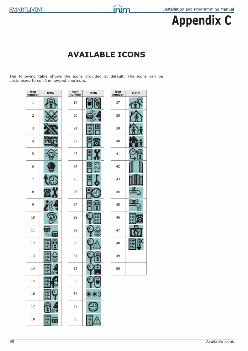
90 Available icons
Installation and Programming Manual
Appendix C
AVAILABLE ICONS
The following table shows the icons provided at default. The icons can becustomized to suit the keypad shortcuts.
icon number ICON icon
number ICON icon number ICON
1 19 37
2 20 38
3 21 39
4 22 40
5 23 41
6 24 42
7 25 43
8 26 44
9 27 45
10 28 46
11 29 47
12 30 48
13 31 49
14 32 50
15 33
16 34
17 35
18 36

Installation and Programming Manual
Voice messages 91
Appendix D
VOICE MESSAGES
The SmartLogos30M voice board provides 500 voice message slots, 291 of whichare pre-recorded at factory. The messages are arranged in such way as toproduce event-related voice calls which clearly describe the related event.The following Table shows the message numbers and their purpose, together withthe respective recording time.
Type Number Default messageMessage duration (seconds)
Type Number Default messageMessage duration (seconds)
High quality Average quality High quality Average
qualityAvailable user-
messages 1 – 100 ‘’169
(for all 100 messages)
271(for all 100 messages)
Zone Terminal
330 Zone 60 3.13 5
None available 101 - 165 ‘’ 331 Zone 61 3.13 5
Arming scenarios
166 Scenario 1 2.5 4 332 Zone 62 3.13 5167 Scenario 2 2.5 4 333 Zone 63 3.13 5168 Scenario 3 2.5 4 334 Zone 64 3.13 5169 Scenario 4 2.5 4 335 Zone 65 3.13 5170 Scenario 5 2.5 4 336 Zone 66 3.13 5171 Scenario 6 2.5 4 337 Zone 67 3.13 5172 Scenario 7 2.5 4 338 Zone 68 3.13 5173 Scenario 8 2.5 4 339 Zone 69 3.13 5174 Scenario 9 2.5 4 340 Zone 70 3.13 5175 Scenario 10 2.5 4 341 Zone 71 3.13 5176 Scenario 11 2.5 4 342 Zone 72 3.13 5177 Scenario 12 2.5 4 343 Zone 73 3.13 5178 Scenario 13 2.5 4 344 Zone 74 3.13 5179 Scenario 14 2.5 4 345 Zone 75 3.13 5180 Scenario 15 2.5 4 346 Zone 76 3.13 5181 Scenario 16 2.5 4 347 Zone 77 3.13 5182 Scenario 17 2.5 4 348 Zone 78 3.13 5183 Scenario 18 2.5 4 349 Zone 79 3.13 5184 Scenario 19 2.5 4 350 Zone 80 3.13 5185 Scenario 20 2.5 4 351 Zone 81 3.13 5186 Scenario 21 2.5 4 352 Zone 82 3.13 5187 Scenario 22 2.5 4 353 Zone 83 3.13 5188 Scenario 23 2.5 4 354 Zone 84 3.13 5189 Scenario 24 2.5 4 355 Zone 85 3.13 5190 Scenario 25 2.5 4 356 Zone 86 3.13 5191 Scenario 26 2.5 4 357 Zone 87 3.13 5192 Scenario 27 2.5 4 358 Zone 88 3.13 5193 Scenario 28 2.5 4 359 Zone 89 3.13 5194 Scenario 29 2.5 4 360 Zone 90 3.13 5195 Scenario 30 2.5 4 361 Zone 91 3.13 5
Shortcuts
196 Armed in Away mode 2.5 4 362 Zone 92 3.13 5197 Stop alarm 2.5 4 363 Zone 93 3.13 5198 Stop call queue 2.5 4 364 Zone 94 3.13 5199 Delete memory 2.5 4 365 Zone 95 3.13 5200 Activate output 2.5 4 366 Zone 96 3.13 5201 Deactivate output 2.5 4 367 Zone 97 3.13 5202 Overtime request 2.5 4 368 Zone 98 3.13 5203 Request maintenance 2.5 4 369 Zone 99 3.13 5204 StartVoiceNotifier 2.5 4 370 Zone 100 3.13 5205 Listen-in 2.5 4
Partition
371 Partition 1 3.13 5206 Intercom Call 2.5 4 372 Partition 2 3.13 5207 Access arm/disarm menu 2.5 4 373 Partition 3 3.13 5208 Access manage alarms menu 2.5 4 374 Partition 4 3.13 5209 Voice menu 2.5 4 375 Partition 5 3.13 5210 Activations menu 2.5 4 376 Partition 6 3.13 5211 View menu 2.5 4 377 Partition 7 3.13 5212 System status 2.5 4 378 Partition 8 3.13 5213 Keypad settings menu 2.5 4 379 Partition 9 3.13 5214 Zone activations menu 2.5 4 380 Partition 10 3.13 5215 Voice memo 2.5 4 381 Partition 11 3.13 5216 Output management menu 2.5 4 382 Partition 12 3.13 5217 Enable/Disable answerphone 2.5 4 383 Partition 13 3.13 5218 Enable teleservice 2.5 4 384 Partition 14 3.13 5219 Enable codes 2.5 4 385 Partition 15 3.13 5220 Enable keys 2.5 4
Codes
386 Code 1 2.5 4221 Enable timers 2.5 4 387 Code 2 2.5 4222 Enable auto-arming 2.5 4 388 Code 3 2.5 4223 View events log 2.5 4 389 Code 4 2.5 4224 View alarms log 2.5 4 390 Code 5 2.5 4225 View faults log 2.5 4 391 Code 6 2.5 4226 View arm/disarm operations 2.5 4 392 Code 7 2.5 4227 View battery status 2.5 4 393 Code 8 2.5 4228 View zone status 2.5 4 394 Code 9 2.5 4229 Change PIN 2.5 4 395 Code 10 2.5 4

92 Voice messages
Installation and Programming Manual
Shortcuts 230 Date/Time settings 2.5 4
Keys
396 Key 1 2.5 4231 Faults list 2.5 4 397 Key 2 2.5 4
None available 232 - 240 ‘’ 398 Key 3 2.5 4
Generic messages
241 Restoral 1.25 2 399 Key 4 2.5 4242 To 0.63 1 400 Key 5 2.5 4243 Press 1.25 2 401 Key 6 2.5 4244 Location 6.25 10 402 Key 7 2.5 4245 Zero 2.5 4 403 Key 8 2.5 4246 One 2.5 4 404 Key 9 2.5 4247 Two 2.5 4 405 Key 10 2.5 4248 Three 2.5 4
Keypads
406 Keypad 1 2.5 4249 Four 2.5 4 407 Keypad 2 2.5 4250 Five 2.5 4 408 Keypad 3 2.5 4251 Six 2.5 4 409 Keypad 4 2.5 4252 Seven 2.5 4 410 Keypad 5 2.5 4253 Eight 2.5 4
Readers
411 Reader 1 2.5 4254 Nine 2.5 4 412 Reader 2 2.5 4
Partition status
255 Away mode 3.13 5 413 Reader 3 2.5 4256 Armed in Stay mode 3.13 5 414 Reader 4 2.5 4257 Instant mode 3.13 5 415 Reader 5 2.5 4258 Disarm 3.13 5
Function keys Emergency
416 Fire 2.5 4
Menu 259 To go back to previous menu press 3.13 5 417 Ambulance 2.5 4
Activation / Deactivation
260 To activate 1.88 3 418 Police 2.5 4261 To deactivate 1.88 3 None available 419 ‘’
Type-in user-code PIN 262 Type-in user-code PIN followed
by # 2.5 4
Event type
420 Zone alarm 2.5 4
Outputs263 Relay 2.5 4 421 Terminal tamper 2.5 4264 Output 1 2.5 4 422 Partition alarm 2.5 4265 Output 2 2.5 4 423 Stay alarm 2.5 4
None available 266 - 270 ‘’ 424 Partition tamper 2.5 4
Zone Terminal
271 Zone 1 3.13 5 425 Zone bypass 2.5 4272 Zone 2 3.13 5 426 Real time zone 2.5 4273 Zone 3 3.13 5 427 Partition not-ready-to-arm 2.5 4274 Zone 4 3.13 5 428 Away arm request 2.5 4275 Zone 5 3.13 5 429 Stay arm request 2.5 4276 Zone 6 3.13 5 430 Armed in Away mode 2.5 4277 Zone 7 3.13 5 431 Armed in Stay mode 2.5 4278 Zone 8 3.13 5 432 Reset partition 2.5 4279 Zone 9 3.13 5 433 Partition armed, leave partition 2.5 4280 Zone 10 3.13 5 434 Disarm partition 2.5 4281 Zone 11 3.13 5 435 Pre-arm alert 2.5 4282 Zone 12 3.13 5 436 Overtime request 2.5 4283 Zone 13 3.13 5 437 Welcome 2.5 4284 Zone 14 3.13 5 438 Forced arming 2.5 4285 Zone 15 3.13 5 439 Failed to arm 2.5 4286 Zone 16 3.13 5 440 Valid user-code 2.5 4287 Zone 17 3.13 5 441 Valid key 2.5 4288 Zone 18 3.13 5 442 Valid user-code at keypad 2.5 4289 Zone 19 3.13 5 443 Valid key at reader 2.5 4290 Zone 20 3.13 5 444 Valid user-code on partition 2.5 4291 Zone 21 3.13 5 445 Valid key on partition 2.5 4292 Zone 22 3.13 5 446 Failed call 2.5 4293 Zone 23 3.13 5 447 Timer activated 2.5 4294 Zone 24 3.13 5 448 Thermostat 2.5 4295 Zone 25 3.13 5 449 Scenario 2.5 4296 Zone 26 3.13 5 450 Programmable event 2.5 4297 Zone 27 3.13 5 451 Emergency 2.5 4298 Zone 28 3.13 5 452 Open-panel tamper 2.5 4299 Zone 29 3.13 5 453 Dislodged-panel tamper 2.5 4300 Zone 30 3.13 5 454 Zone fuse fault 2.5 4301 Zone 31 3.13 5 455 I-BUS fuse fault 2.5 4302 Zone 32 3.13 5 456 Battery fault 2.5 4303 Zone 33 3.13 5 457 Mains failure 2.5 4304 Zone 34 3.13 5 458 Expansion tamper 2.5 4305 Zone 35 3.13 5 459 Keypad Tamper 2.5 4306 Zone 36 3.13 5 460 Reader Tamper 2.5 4307 Zone 37 3.13 5 461 Sounder flasher tamper 2.5 4308 Zone 38 3.13 5 462 Nexus tamper 2.5 4309 Zone 39 3.13 5 463 Expansion Loss 2.5 4310 Zone 40 3.13 5 464 Keypad Loss 2.5 4311 Zone 41 3.13 5 465 Reader Loss 2.5 4312 Zone 42 3.13 5 466 Sounder flasher loss 2.5 4313 Zone 43 3.13 5 467 Nexus loss 2.5 4314 Zone 44 3.13 5 468 Jamming 2.5 4315 Zone 45 3.13 5 469 Low battery wireless zone 2.5 4316 Zone 46 3.13 5 470 Wireless zone loss 2.5 4317 Zone 47 3.13 5 471 Valid Installer code 2.5 4318 Zone 48 3.13 5 472 Invalid code319 Zone 49 3.13 5 473 False key320 Zone 50 3.13 5 474 Nexus fault321 Zone 51 3.13 5 475 Telephone line down322 Zone 52 3.13 5 476 Periodic test event 323 Zone 53 3.13 5 477 Hard reset324 Zone 54 3.13 5 478 Call queue full325 Zone 55 3.13 5 479 Successful call326 Zone 56 3.13 5 480 Initialize programming327 Zone 57 3.13 5 481 Ongoing call328 Zone 58 3.13 5 482 Failed to send message329 Zone 59 3.13 5 483 Output fault330 Zone 60 3.13 5 None available 484 – 485 ‘’
Voice memo slots 486 – 500 ‘’
37.5(for all 15 messages)
60(for all 15 messages)
Type Number Default messageMessage duration (seconds)
Type Number Default messageMessage duration (seconds)
High quality Average quality High quality Average
quality

Installation and Programming Manual
Screw Terminals 93
Appendix E
SCREW TERMINALS
All the terminals on the SmartLiving control panel and its peripherals (expansionsand keypads) are identified by distinctive numbers transcribed in the “CCC”programming field of the “CONTACT-ID” protocol, in order to allow the preciselocalization of events related to zones or terminals.In the case of double zones, the second zone will be identified by the number“500 + n.” (where “n.” stands for the number of the terminal).
n. SLiving505
SLiving515
SLiving1050
SLiving10100 n. SLiving
515SLiving1050
SLiving10100 n. SLiving
1050SLiving10100 n. SLiving
10100
1 Panel T1 Panel T1 Panel T1 Panel T1 61 Keyp. 1 T1 Exp. 11 T1 Exp. 11 T1 121 Keyp. 6 T1 Exp. 23 T1 181 Exp. 35 T12 Panel T2 Panel T2 Panel T2 Panel T2 62 Keyp. 1 T2 Exp. 11 T2 Exp. 11 T2 122 Keyp. 6 T2 Exp. 23 T2 182 Exp. 35 T23 Panel T3 Panel T3 Panel T3 Panel T3 63 Keyp. 2 T1 Exp. 11 T3 Exp. 11 T3 123 Keyp. 7 T1 Exp. 23 T3 183 Exp. 35 T34 Panel T4 Panel T4 Panel T4 Panel T4 64 Keyp. 2 T2 Exp. 11 T4 Exp. 11 T4 124 Keyp. 7 T2 Exp. 23 T4 184 Exp. 35 T45 Panel T5 Panel T5 Panel T5 Panel T5 65 Keyp. 3 T1 Exp. 11 T5 Exp. 11 T5 125 Keyp. 8 T1 Exp. 23 T5 185 Exp. 35 T56 Panel T6 Panel T6 66 Keyp. 3 T2 Exp. 12 T1 Exp. 12 T1 126 Keyp. 8 T2 Exp. 24 T1 186 Exp. 36 T17 Panel T7 Panel T7 67 Keyp. 4 T1 Exp. 12 T2 Exp. 12 T2 127 Keyp. 9 T1 Exp. 24 T2 187 Exp. 36 T28 Panel T8 Panel T8 68 Keyp. 4 T2 Exp. 12 T3 Exp. 12 T3 128 Keyp. 9 T2 Exp. 24 T3 188 Exp. 36 T39 Panel T9 Panel T9 69 Keyp. 5 T1 Exp. 12 T4 Exp. 12 T4 129 Keyp. 10 T1 Exp. 24 T4 189 Exp. 36 T410 Panel T10 Panel T10 70 Keyp. 5 T2 Exp. 12 T5 Exp. 12 T5 130 Keyp. 10 T2 Exp. 24 T5 190 Exp. 36 T511 Exp. 1 T1 Exp. 1 T1 Exp. 1 T1 Exp. 1 T1 71 Exp. 13 T1 Exp. 13 T1 131 Exp. 25 T1 191 Exp. 37 T112 Exp. 1 T2 Exp. 1 T2 Exp. 1 T2 Exp. 1 T2 72 Exp. 13 T2 Exp. 13 T2 132 Exp. 25 T2 192 Exp. 37 T213 Exp. 1 T3 Exp. 1 T3 Exp. 1 T3 Exp. 1 T3 73 Exp. 13 T3 Exp. 13 T3 133 Exp. 25 T3 193 Exp. 37 T314 Exp. 1 T4 Exp. 1 T4 Exp. 1 T4 Exp. 1 T4 74 Exp. 13 T4 Exp. 13 T4 134 Exp. 25 T4 194 Exp. 37 T415 Exp. 1 T5 Exp. 1 T5 Exp. 1 T5 Exp. 1 T5 75 Exp. 13 T5 Exp. 13 T5 135 Exp. 25 T5 195 Exp. 37 T516 Exp. 2 T1 Exp. 2 T1 Exp. 2 T1 Exp. 2 T1 76 Exp. 14 T1 Exp. 14 T1 136 Exp. 26 T1 196 Exp. 38 T117 Exp. 2 T2 Exp. 2 T2 Exp. 2 T2 Exp. 2 T2 77 Exp. 14 T2 Exp. 14 T2 137 Exp. 26 T2 197 Exp. 38 T218 Exp. 2 T3 Exp. 2 T3 Exp. 2 T3 Exp. 2 T3 78 Exp. 14 T3 Exp. 14 T3 138 Exp. 26 T3 198 Exp. 38 T319 Exp. 2 T4 Exp. 2 T4 Exp. 2 T4 Exp. 2 T4 79 Exp. 14 T4 Exp. 14 T4 139 Exp. 26 T4 199 Exp. 38 T420 Exp. 2 T5 Exp. 2 T5 Exp. 2 T5 Exp. 2 T5 80 Exp. 14 T5 Exp. 14 T5 140 Exp. 26 T5 200 Exp. 38 T521 Exp. 3 T1 Exp. 3 T1 Exp. 3 T1 Exp. 3 T1 81 Exp. 15 T1 Exp. 15 T1 141 Exp. 27 T1 201 Exp. 39 T122 Exp. 3 T2 Exp. 3 T2 Exp. 3 T2 Exp. 3 T2 82 Exp. 15 T2 Exp. 15 T2 142 Exp. 27 T2 202 Exp. 39 T223 Exp. 3 T3 Exp. 3 T3 Exp. 3 T3 Exp. 3 T3 83 Exp. 15 T3 Exp. 15 T3 143 Exp. 27 T3 203 Exp. 39 T324 Exp. 3 T4 Exp. 3 T4 Exp. 3 T4 Exp. 3 T4 84 Exp. 15 T4 Exp. 15 T4 144 Exp. 27 T4 204 Exp. 39 T425 Exp. 3 T5 Exp. 3 T5 Exp. 3 T5 Exp. 3 T5 85 Exp. 15 T5 Exp. 15 T5 145 Exp. 27 T5 205 Exp. 39 T526 Exp. 4 T1 Exp. 4 T1 Exp. 4 T1 Exp. 4 T1 86 Exp. 16 T1 Exp. 16 T1 146 Exp. 28 T1 206 Exp. 40 T127 Exp. 4 T2 Exp. 4 T2 Exp. 4 T2 Exp. 4 T2 87 Exp. 16 T2 Exp. 16 T2 147 Exp. 28 T2 207 Exp. 40 T228 Exp. 4 T3 Exp. 4 T3 Exp. 4 T3 Exp. 4 T3 88 Exp. 16 T3 Exp. 16 T3 148 Exp. 28 T3 208 Exp. 40 T329 Exp. 4 T4 Exp. 4 T4 Exp. 4 T4 Exp. 4 T4 89 Exp. 16 T4 Exp. 16 T4 149 Exp. 28 T4 209 Exp. 40 T430 Exp. 4 T5 Exp. 4 T5 Exp. 4 T5 Exp. 4 T5 90 Exp. 16 T5 Exp. 16 T5 150 Exp. 28 T5 210 Exp. 40 T531 Keyp. 1 T1 Exp. 5 T1 Exp. 5 T1 Exp. 5 T1 91 Exp. 17 T1 Exp. 17 T1 151 Exp. 29 T1 211 Keyp. 1 T132 Keyp. 1 T2 Exp. 5 T2 Exp. 5 T2 Exp. 5 T2 92 Exp. 17 T2 Exp. 17 T2 152 Exp. 29 T2 212 Keyp. 1 T233 Keyp. 2 T1 Exp. 5 T3 Exp. 5 T3 Exp. 5 T3 93 Exp. 17 T3 Exp. 17 T3 153 Exp. 29 T3 213 Keyp. 2 T134 Keyp. 2 T2 Exp. 5 T4 Exp. 5 T4 Exp. 5 T4 94 Exp. 17 T4 Exp. 17 T4 154 Exp. 29 T4 214 Keyp. 2 T235 Keyp. 3 T1 Exp. 5 T5 Exp. 5 T5 Exp. 5 T5 95 Exp. 17 T5 Exp. 17 T5 155 Exp. 29 T5 215 Keyp. 3 T136 Keyp. 3 T2 Exp. 6 T1 Exp. 6 T1 Exp. 6 T1 96 Exp. 18 T1 Exp. 18 T1 156 Exp. 30 T1 216 Keyp. 3 T237 Keyp. 4 T1 Exp. 6 T2 Exp. 6 T2 Exp. 6 T2 97 Exp. 18 T2 Exp. 18 T2 157 Exp. 30 T2 217 Keyp. 4 T138 Keyp. 4 T2 Exp. 6 T3 Exp. 6 T3 Exp. 6 T3 98 Exp. 18 T3 Exp. 18 T3 158 Exp. 30 T3 218 Keyp. 4 T239 Keyp. 5 T1 Exp. 6 T4 Exp. 6 T4 Exp. 6 T4 99 Exp. 18 T4 Exp. 18 T4 159 Exp. 30 T4 219 Keyp. 5 T140 Keyp. 5 T2 Exp. 6 T5 Exp. 6 T5 Exp. 6 T5 100 Exp. 18 T5 Exp. 18 T5 160 Exp. 30 T5 220 Keyp. 5 T241 Exp. 7 T1 Exp. 7 T1 Exp. 7 T1 101 Exp. 19 T1 Exp. 19 T1 161 Exp. 31 T1 221 Keyp. 6 T14 Exp. 7 T2 Exp. 7 T2 Exp. 7 T2 102 Exp. 19 T2 Exp. 19 T2 162 Exp. 31 T2 222 Keyp. 6 T243 Exp. 7 T3 Exp. 7 T3 Exp. 7 T3 103 Exp. 19 T3 Exp. 19 T3 163 Exp. 31 T3 223 Keyp. 7 T144 Exp. 7 T4 Exp. 7 T4 Exp. 7 T4 104 Exp. 19 T4 Exp. 19 T4 164 Exp. 31 T4 224 Keyp. 7 T245 Exp. 7 T5 Exp. 7 T5 Exp. 7 T5 105 Exp. 19 T5 Exp. 19 T5 165 Exp. 31 T5 225 Keyp. 8 T146 Exp. 8 T1 Exp. 8 T1 Exp. 8 T1 106 Exp. 20 T1 Exp. 20 T1 166 Exp. 32 T1 226 Keyp. 8 T247 Exp. 8 T2 Exp. 8 T2 Exp. 8 T2 107 Exp. 20 T2 Exp. 20 T2 167 Exp. 32 T2 227 Keyp. 9 T148 Exp. 8 T3 Exp. 8 T3 Exp. 8 T3 108 Exp. 20 T3 Exp. 20 T3 168 Exp. 32 T3 228 Keyp. 9 T249 Exp. 8 T4 Exp. 8 T4 Exp. 8 T4 109 Exp. 20 T4 Exp. 20 T4 169 Exp. 32 T4 229 Keyp. 10 T150 Exp. 8 T5 Exp. 8 T5 Exp. 8 T5 110 Exp. 20 T5 Exp. 20 T5 170 Exp. 32 T5 230 Keyp. 10 T251 Exp. 9 T1 Exp. 9 T1 Exp. 9 T1 111 Keyp. 1 T1 Exp. 21 T1 171 Exp. 33 T1 231 Keyp. 11 T152 Exp. 9 T2 Exp. 9 T2 Exp. 9 T2 112 Keyp. 1 T2 Exp. 21 T2 172 Exp. 33 T2 232 Keyp. 11 T253 Exp. 9 T3 Exp. 9 T3 Exp. 9 T3 113 Keyp. 2 T1 Exp. 21 T3 173 Exp. 33 T3 233 Keyp. 12 T154 Exp. 9 T4 Exp. 9 T4 Exp. 9 T4 114 Keyp. 2 T2 Exp. 21 T4 174 Exp. 33 T4 234 Keyp. 12 T255 Exp. 9 T5 Exp. 9 T5 Exp. 9 T5 115 Keyp. 3 T1 Exp. 21 T5 175 Exp. 33 T5 235 Keyp. 13 T156 Exp. 10 T1 Exp. 10 T1 Exp. 10 T1 116 Keyp. 3 T2 Exp. 22 T1 176 Exp. 34 T1 236 Keyp. 13 T257 Exp. 10 T2 Exp. 10 T2 Exp. 10 T2 117 Keyp. 4 T1 Exp. 22 T2 177 Exp. 34 T2 237 Keyp. 14 T158 Exp. 10 T3 Exp. 10 T3 Exp. 10 T3 118 Keyp. 4 T2 Exp. 22 T3 178 Exp. 34 T3 238 Keyp. 14 T259 Exp. 10 T4 Exp. 10 T4 Exp. 10 T4 119 Keyp. 5 T1 Exp. 22 T4 179 Exp. 34 T4 239 Keyp. 15 T160 Exp. 10 T5 Exp. 10 T5 Exp. 10 T5 120 Keyp. 5 T2 Exp. 22 T5 180 Exp. 34 T5 240 Keyp. 15 T2

94 Combination of outputs triggered by events
Installation and Programming Manual
Appendix F
COMBINATION OF OUTPUTSTRIGGERED BY EVENTS
This appendix shows the event-generated actions (activations/deactivations) ofthe outputs programmed in the “Outputs” and “Other outputs” sections combinedwith the “SirenSound types” of the sounderflashers on the BUS.
Table 43: Output typologySymbol/Initials Description
TM Output on terminal/Relay/OC1/OC2 - monostableTB Output on terminal/Relay/OC1/OC2 - bistableSM Sounderflasher output with limited flasher timeSB Sounderflasher output with unlimited flasher time
Table 44: Functioning and deactivation of the outputsSymbol/Initials Description
AThese outputs will deactivate if a Stop alarm, Reset partition or Disarm operation is carried out while the monostable time of the main output is running.
B These outputs will deactivate only when the event clears after expiry of the monostable time of the main output.
C
These outputs, due to the continuous flasher function, will not deactivate automatically.In order to deactivate the SB flashers of the sounderflasher after expiry of the monostable time applied to the main output, you must:• trigger an event which applies a Stop pattern to the SB flashers• reset the partition
D These outputs will deactivate only when the event clears.
E These outputs will deactivate if, when an event is active, a Stop alarm operation, reset or disarm partition command operation is carried out.
F
These outputs, due to the continuous flasher function, will not deactivate automatically. In order to deactivate the SB flashers of the device on termination of the event, you must:• trigger an event which applies a Stop pattern to the SB flashers• reset the partition
G These outputs will deactivate when the respective monostable time expires
Table 45: Output combinations
Event groupsPrincipal output Other outputs
TM TB SM SB TM TB SM SB
Zone Alarmterminal tamperpartition alarm
partition tamper
A G A G A B A G A CD E E G D G E G F
A G A G A B A G A CF E G D G E G F
Control panel openDislodged panel
Expansion tamper/lossKeypad tamper/loss Reader tamper/loss
Sounderflasher tamper/lossJamming
Wireless zone lossTelephone line down
A G A G A D A G A C
D E E G D G E G C
A G A G A B A G A C
F E G D G E G C
other events
G G B G CD G D G F
G G B G CF G C G C

Installation and Programming Manual
Compliancy with the regulations in force 95
Appendix G
COMPLIANCY WITH THEREGULATIONS IN FORCE
In order to guarantee compliancy with the regulations in force, you must adhereto the following guidelines:• nBy/X readers must be equipped with devices which protect them against the
forced-opening and dislodgement of their casings from their locations, incompliance with Level 2, as indicated in paragraph 3-2-5 Installing nBy/Xreaders.
• The Tamper NO dislodgement-tamper-protection device of the control panelmust be installed.
• JOY, nCode and Concept keypads must be equipped with enabled tamper-protection devices, as indicated in paragraph 3-3-1 Addressing the keypads.
• FLEX5/U expansion boards must be either mounted inside the metal enclosureof the 1050L or 10100L control panel, or equipped with devices which protectthem against the forced-opening of their casings and dislodgement from theirlocations, in compliance with Performance level 2.
• The lines relating to the intrusion-detection zones must be configured as'Double balancing' with double EOL resistors, or as Single balancing withsingle EOL resistor. They must also be equipped with devices which protectthem against the forced-opening of their casings.
• Terminal tamper, peripheral tamper and control-panel tamper events musttrigger audible signals (sounder signals) for a period of not less than 3minutes.
• The output activated by the previously mentioned tamper events must bedifferent from the output activated by alarms signals.
• All Code PINs must have 6 digits.• If a Timer is used for automatic-arming operations, the Pre-arm times must be
programmed separately for each partition (the Pre-arm time must not be setat 0).
CEI 79-2In particular, in order to guarantee CEI 79-2 compliancy of devices, the followingoptions must be programmed as follows.• The following options must not be activated in the “Panel Options” section:
•• ReaderBuzzer OFF•• BypassAlsoTamper•• OpenZonesArmLock•• 50131ReaderLedOFF•• 50131StatHidden•• 50131IconsHidden•• 50131AlarDelayed•• 50131WarnLedMem
• All of the “FaultsNotReady” options - from the “Other parameters” section -must be disabled.
• The “Requires code” option - from the “Keypads - Choose peripheral - Options”section - must be enabled for every keypad and shortcut in use.
• The “Entry Time” parameter of each partition must be no more than 60seconds.
EN50131Compliancy with EN50131 Grade 2 is guaranteed by observing the followingguidelines.• In the “Panel options” section, enable:
•• Keypad lockout•• OpenZonesArmLock•• NoUserTamp.reset•• 50131ReaderLedOFF

96 Compliancy with the regulations in force
Installation and Programming Manual
•• 50131StatHidden•• 50131IconsHidden•• 50131AlarDelayed•• 50131WarnLedMem
• The following options must not be activated in the “Panel Options” section:•• ReaderBuzzer OFF•• BypassAlsoTamper
• In the section “Other parameters - FaultNotReady”, enable the followingoptions:•• Zone fuse fault•• IBUS fuse fault•• Low battery•• Mains failure•• Tel. line down•• Jamming•• Low battery WLS•• WLS zone loss•• LossTamp.ongoing
• Zones configured as “24H”, “Automation” are non-compliant.• Zones programmed as “Arm”, “Disarm”, “Switch” or “Follow” comply only when
activated by keyswitches with more than 10,000 code combinations.• An input is set up for system fault management.• You must delete any programming relating to outdoor sounderflashers - from
the respective alarm event in the “Outputs” section - for all zones with the“Fault Zone” attribute. You can pogramme indoor sounderflashers via the“Other outputs” option.
• The telephone dialer must be enabled.• The system must include a self-powered sounderflasher for intrusion-alarm
event signaling• If you use a digital dialer or voice dialer with SmartLogos30M board for
transmissions, a telephone number must be reserved for the following events:•• All events generated by zones with the “Hold-up” attribute.•• All events generated by “Instant”, “Delayed”, “Delayed unhidden” and
“Route”•• All events generated by terminal, peripheral and control panel tamper.•• All faults detected by the control panel.
• The “Alarm Cycles” parameter of each zone must be set between 3 and 10.• The “Mains fail.Delay” parameter must be set at no more than 1 minute.• The “Requires code” option on the function-key shortcuts must be enabled for
all the assigned shortcuts.• The “StopTelOn Disarm” partition option must not be enabled.• The “Entry Time” of each partition must be set at a maximum of 45 seconds.• You must enable the “Priority” option for any alarm events associated with
“Hold-up” zones.• “Failed to arm” and “Forced arming”events must be saved to the Events log.• The programmed “LowBattery delay” must not be programmed at more than 5
minutes.

Installation and Programming Manual
Order Codes 97
Appendix H
ORDER CODES
Please quote the following order codes when ordering items from the INIMElectronics product range:
Access Codes Product descriptionAir2-BS100 Wireless transceiverAir2-IRF100 Wireless PIR with 12m coverageAir2-KF100 4 button remote-control keyfobAir2-MC100 Wireless magnetic contact with 2 inputs/outputsAUXREL32 Power distribution relay-board for SmartLiving 1050L and 10100L
Concept/GN Touch keypad with backlit graphic display and keys equipped with input/output terminalDCMIINE0SLIVINGE SmartLiving Installation and Programming ManualDCMUINE0SLIVINGE SmartLiving User's Manual
Flex5/P Two-way Input/Output expansion board in tamper-protected plastic enclosureFlex5/U Two-way Input/Output expansion board transparent plastic enclosure with terminal on viewIB100/A BUS isolator with data and power regeneration and tamper protection
IB100/RP BUS isolator with data regeneration and tamper protectionIB100/RU BUS isolator with data regeneration and on-view terminals
Ivy Self-powered sounderflasher - suitable for outdoor installationIvy-B Self-powered sounderflasher with BUS connection capacity - suitable for outdoor installation
Ivy-BF Self-powered sounderflasher with BUS connection capacity and foam-tamper protection - suitable for outdoor installation
Ivy-BFM Self-powered sounderflasher with BUS connection capacity and foam-tamper in metal-look (chrome) enclosure - suitable for outdoor installation
Ivy-BM Self-powered sounderflasher with BUS connection capacity in metal-look (chrome) enclosure - suitable for outdoor installation
Ivy-F Self-powered sounderflasher with foam-tamper protection - suitable for outdoor installation
Ivy-FM Self-powered sounderflasher with foam-tamper protection in metal-look (chrome) enclosure - suitable for outdoor installation
Ivy-M Self-powered sounderflasher in metal-look (chrome) enclosure - suitable for outdoor installationJoy/GR Keypad with backlit graphic display with two input/output terminals
Joy/MAX Keypad with backlit graphic display with two input/output terminals and built-in proximity reader, microphone, speaker and temperature sensor
LINK232F9F9 RS232 cable link to PC and/or INIM devicesLINKIBUS Temporary cable link for I-BUS
LINKUSABAB USB cable link to PC and/or INIM devicesnBy/S Wall-mount proximity readernBy/X Flush-mount proximity readernCard Card for nBy proximity readers
nCode/G Keypad with backlit graphic display with one input/output terminalNexus BUS connectable GSM DialernKey Tag for nBy proximity readers
ProbeTH Thermal probe for battery-charge optimizationSmartLAN/G Ethernet interface for programming and internet operations using TCP-IP and UDP protocolsSmartLAN/SI Ethernet interface for programming via internet using TCP-IP and UDP protocolsSmartLeague
software programme Programming and management software for INIM devices
SmartLink/GWB SmartLink/G Kit for SmartLiving 1050L and 10100LSmartLink/REM-ANT Remote Antenna (3 meters)
SmartLiving10100L Intrusion control panel: manages 10 to 100 terminals, 15 partitions, switching power supply @5A, optional TCP/IP connectivity, comes in metal enclosure with housing for 1 battery @17Ah
SmartLiving 1050 Intrusion control panel: manages 10 to 50 terminals, 10 partitions, switching power supply @3A, comes in metal enclosure with housing for 1 battery @7Ah
SmartLiving1050L Intrusion control panel: manages 10 to 50 terminals, 10 partitions, switching power supply @3A, comes in metal enclosure with housing for 1 battery @17Ah
SmartLiving 505 Intrusion control panel: manages 5 terminals, 5 partitions, switching power supply @ 1.2A, comes in metal enclosure with housing for 1 battery @7Ah
SmartLiving515 Intrusion control panel: manages 5 to 10 terminals, 5 partitions, switching power supply @ 1.2A, comes in metal enclosure with housing for 1 battery @7Ah
SmartLogos30M Voice board (for SmartLiving)SmartLook SmartLook is a centralized-control programme for INIM's fire detection and intrusion control systems

98 Order Codes
Installation and Programming Manual
SmartModem100 Remote programming modemSPS12040 Switching power supply/battery charger in enclosure - 3A, 12VSPS12100 Switching power supply/battery charger in enclosure - 5A, 12VTamperNO Dislodgement-tamper device for SmartLiving control panels
DCM
IIN
E0SLI
VIN
GE-
R41
0-20
1107
20

Installation and Programming Manual
99
Notes

Azienda certificata ISO 9001 : 2008
via Fosso AnticoLoc. Centobuchi63076 Monteprandone(AP) ITALY
Tel. +39 0735 705007Fax +39 0735 704912
ISO 9001:2008 Registered company