Embed Size (px)
Citation preview
Maestría en Aplicaciones Espaciales de alerta y Respuesta Temprana a Emergencias
Comisión Nacional de Actividades Espaciales
Seminar
“LIDAR”
Author: Molina Wladimir
September, 2014
INDEX
LIDAR .......................................................................................................................... 2
How LIDAR works ...................................................................................................... 2
Scaterring....................................................................................................................... 4 Rayleigh scattering ................................................................................................. 4 Mie Scattering ........................................................................................................ 5 Raman scattering .................................................................................................... 5 Fluorescence ........................................................................................................... 6
Detectors........................................................................................................................ 6 Photomultipliers ..................................................................................................... 6 Photo-Diode............................................................................................................. 7 Solic Stated Detectors.............................................................................................. 8
Detection........................................................................................................................ 8 Heterodyne detection............................................................................................... 8
Desing ........................................................................................................................... 9 Laser ....................................................................................................................... 10 Scanner and optics .................................................................................................. 11 Photodetector and receiver electronics ................................................................... 11 Position and navigation systems.............................................................................. 11
Most important Applications.......................................................................................... 12Geology and soil science......................................................................................... 12Atmospheric Remote Sensing and Meteorology..................................................... 12Agriculture............................................................................................................... 13
LIDAR software generalities......................................................................................... 14Free LiDAR Tools................................................................................................... 14ENVI LiDAR ......................................................................................................... 15
Bibliography .................................................................................................................. 15
INTRODUCTION
The LIDAR technology is worldwide used to a lot of applications in topography studies, agriculture, archeology, Atmospheric Remote Sensing and Meteorology, Physics and astronomy, geology and soil science and most important Physical of Remote Sensing and astronomy due to its capacity to generate a reliable estimation to the distance between a point to another, just known the time of travel of the light from the source of LIDAR laser to a target object and the return thereof, the basics involve LIDAR operation is complex, especially the discretization and detection operation, but in this summary will be try to do a explication of all LIDAR procedures, in a pleasant and concisely way.
LIDAR
LIDAR is a technology that allows to estimate the distance by illuminating a target with a laser and analyzing the reflected light. The term LIDAR was created as a portmanteau of "light" and "radar"[1].
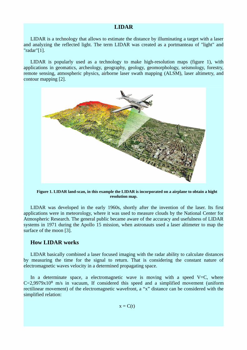
LIDAR is popularly used as a technology to make high-resolution maps (figure 1), with applications in geomatics, archeology, geography, geology, geomorphology, seismology, forestry, remote sensing, atmospheric physics, airborne laser swath mapping (ALSM), laser altimetry, and contour mapping [2].
Figure 1. LIDAR land-scan, in this example the LIDAR is incorporated on a airplane to obtain a hight resolution map.
LIDAR was developed in the early 1960s, shortly after the invention of the laser. Its first applications were in meteorology, where it was used to measure clouds by the National Center for Atmospheric Research. The general public became aware of the accuracy and usefulness of LIDAR systems in 1971 during the Apollo 15 mission, when astronauts used a laser altimeter to map the surface of the moon [3].
How LIDAR works
LIDAR basically combined a laser focused imaging with the radar ability to calculate distances by measuring the time for the signal to return. That is considering the constant nature of electromagnetic waves velocity in a determined propagating space.
In a determinate space, a electromagnetic wave is moving with a speed V=C, where C=2,9979x10 m/s in vacuum, If considered this speed and a⁸ simplified movement (uniform rectilinear movement) of the electromagnetic wavefront, a “x” distance can be considered with the simplified relation:
x = C(t)
Now, the “x” distance is a combination of two electromagnetic wave travel movements, first the movement of LIDAR laser source to object target (x'), and second the return movement of scatter radiation from object target to the LIDAR's photodetector (x''), the above equation can be rewrite like a component of two covered distances:
(x'+x'') = C(t)
However, the speed of a electromagnetic wave propagating in any space can be considered much greater than any other object in movement beside it (like an airplane, a satellite, etc), so that in the travel of electromagnetic wavefront to the object target and its return to LIDAR source, the LIDAR position can be regarded undisturbed, in this context the distance x' can be considered equal to x'', so the two covered distances equation can be rewrite like:
2x'= C(t) or 2x''= C(t)
The recovered distance to target object to LIDAR source (in this simplified example) is:
x''= C(t)/2
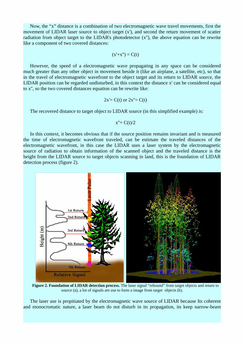
In this context, it becomes obvious that if the source position remains invariant and is measured the time of electromagnetic wavefront traveled, can be estimate the traveled distances of the electromagnetic wavefront, in this case the LIDAR uses a laser system by the electromagnetic source of radiation to obtain information of the scanned object and the traveled distance is the height from the LIDAR source to target objects scanning in land, this is the foundation of LIDAR detection process (figure 2).
Figure 2. Foundation of LIDAR detection process. The laser signal “rebound” from target objects and return to source (a), a lot of signals are use to form a image from target objects (b).
The laser use is propitiated by the electromagnetic wave source of LIDAR because Its coherent and monocromatic nature, a laser beam do not disturb in its propagation, its keep narrow-beam
shape so that if one takes security of the site which is pointing, can be sure that the return signal throw information of focused spot and not another point about this.
It becomes obvious too that in a different space of vacuum, the above relation showed is too simplified. The speed of a electromagnetic wave is affected and it change in a space different to vacuum, calibration factors that reflect reality are necessary to establish the correct speed of any electromagnetic wave involved in the retrodispersion process, also the nature of incident and scatter radiation interacting with the different target objects becomes necessary the implementation of advanced methods to detection and discrimination of all electromagnetic wave arrived to the detector and a adaptation system to accommodate the incident wavelengths LIDAR laser in target objects.
In this context, in a LIDAR, Laser wavelengths vary to suit the target: from about 10 micrometers to the UV (approximately 250 nm). Different types of scattering are used for different LIDAR applications: most commonly Rayleigh scattering, Mie scattering, Raman scattering, and fluorescence. Based on different kinds of backscattering, the LIDAR can be accordingly called Rayleigh LIDAR, Mie LIDAR Raman LIDAR, Na/Fe/K Fluorescence LIDAR, and so on [2]. Suitable combinations of wavelengths can allow for remote mapping of atmospheric contents by identifying wavelength-dependent changes in the intensity of the returned signal.
About the scattering, a review of the different kinds of scattering are necessary to understand the LIDAR basics ans process, a review to next.
Scattering
Differents kinds of scattering obtained in LIDAR studies can be:
Rayleigh scattering:
Is the (dominantly) elastic scattering of light or other electromagnetic radiation by particles much smaller than the wavelength of the light. After the Rayleigh scattering the state of material remains unchanged, hence Rayleigh scattering is also said to be a parametric process. The particles may be individual atoms or molecules. It can occur when light travels through transparent solids and liquids, but is most prominently seen in gases. Rayleigh scattering results from the electric polarizability of the particles. The oscillating electric field of a light wave acts on the charges within a particle, causing them to move at the same frequency. The particle therefore becomes a small radiating dipole whose radiation we see as scattered light.
Scattering by particles similar to, or larger than, the wavelength of light is typically treated by the Mie theory, the discrete dipole approximation and other computational techniques. Rayleigh scattering applies to particles that are small with respect to wavelengths of light, and that are optically "soft" (i.e. with a refractive index close to 1). On the other hand, Anomalous Diffraction Theory applies to optically soft but larger particles.
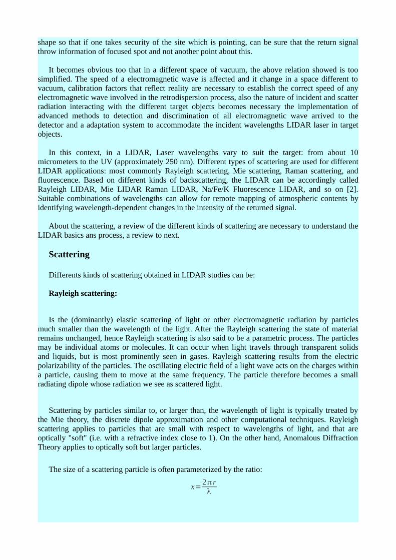
The size of a scattering particle is often parameterized by the ratio:
x=2π rλ
Where r is its characteristic length (radius) and λ is the wavelength of the light. The amplitude of light scattered from within any transparent dielectric is proportional to the inverse square of its wavelength and to the volume of material, that is to the cube of its characteristic length. The wavelength dependence is characteristic of dipole scattering and the volume dependence will apply to any scattering mechanism. Objects with x 1 act as geometric shapes, scattering light according≫ to their projected area. At the intermediate x 1 of Mie scattering, interference effects develop≃ through phase variations over the object's surface. Rayleigh scattering applies to the case when the scattering particle is very small (x 1, with a particle size < 1 /10 wavelength) and the whole≪ surface re-radiates with the same phase. Because the particles are randomly positioned, the scattered light arrives at a particular point with a random collection of phases; it is incoherent and the resulting intensity is just the sum of the squares of the amplitudes from each particle and therefore proportional to the inverse fourth power of the wavelength and the sixth power of its size [4]. In detail, the intensity I of light scattered by any one of the small spheres of diameter d and refractive index n from a beam of unpolarized light of wavelength λ and intensity I0 is given by
I=Io1+cos²θ
2 R² (2πλ )
4
( n²−1n²+2 )
2
( d2 )
6
where R is the distance to the particle and θ is the scattering angle. Averaging this over all angles gives the Rayleigh scattering cross-section.
σ s=2π
5
3d6
λ4 ( n²−1
n²+2 )2
Mie Scattering:
The Mie solution to Maxwell's equations describes the scattering of electromagnetic radiation by a sphere. The solution takes the form of an infinite series.
It can be seen from the above equation that Rayleigh scattering is strongly dependent upon the size of the particle and the wavelengths. The intensity of the Rayleigh scattered radiation increases rapidly as the ratio of particle size to wavelength increases. Furthermore, the intensity of Rayleigh scattered radiation is identical in the forward and reverse directions.
The Rayleigh scattering model breaks down when the particle size becomes larger than around 10% of the wavelength of the incident radiation. In the case of particles with dimensions greater than this, Mie's scattering model can be used to find the intensity of the scattered radiation. The intensity of Mie scattered radiation is given by the summation of an infinite series of terms rather than by a simple mathematical expression. It can be shown, however, that Mie scattering differs from Rayleigh scattering in several respects; it is roughly independent of wavelength and it is larger in the forward direction than in the reverse direction. The greater the particle size, the more of the light is scattered in the forward direction [5].
Raman scattering
Raman effect is the inelastic scattering of a photon. When photons are scattered from an atom or molecule, most photons are elastically scattered (Rayleigh scattering), such that the scattered photons have the same energy (frequency and wavelength) as the incident photons. A small fraction
of the scattered photons (approximately 1 in 10 million) are scattered by an excitation, with the scattered photons having a frequency different from, and usually lower than, that of the incident photons[6]. In a gas, Raman scattering can occur with a change in energy of a molecule due to a transition.
Typically, photons from the laser beam produce an oscillating polarization in the molecules, exciting them to a virtual energy state. The oscillating polarization of the molecule can couple with other possible polarizations of the molecule, including vibrational and electronic excitations. If the polarization in the molecule does not couple to these other possible polarization, then it will not change the vibrational state that the molecule started in and the scattered photon will have the same energy as the original photon. This type of scattering is known as Rayleigh scattering.
When the polarization in the molecules couples to a vibrational state that is higher in energy than the state they started in, then the original photon and the scattered photon differ in energy by the amount required to vibrationally excite the molecule. In perturbation theory, the Raman effect corresponds to the absorption and subsequent emission of a photon via an intermediate quantum state of a material. The intermediate state can be either a "real", i.e., stationary state or a virtual state.
Fluorescence
Is the emission of light by a substance that has absorbed light or other electromagnetic radiation. It also occurs when molecules are excited to higher electronic states by energetic electron bombardment, such as occurs, for example, in the natural aurora, high-altitude nuclear explosions, and rocket-borne electron gun experiments. It is a form of luminescence. In most cases, the emitted light has a longer wavelength, and therefore lower energy, than the absorbed radiation. However, when the absorbed electromagnetic radiation is intense, it is possible for one electron to absorb two photons; this two-photon absorption can lead to emission of radiation having a shorter wavelength than the absorbed radiation. The emitted radiation may also be of the same wavelength as the absorbed radiation, termed "resonance fluorescence".
Already considered all possible scattering obtained in LIDAR studies, the next link is based on the characteristics of LIDAR sensors, a summary of potential seonsores LIDAR and detectors is shown below
Detectors
Detection capability of LIDAR depends almost exclusively on the type of detector used and its material, the types of LIDAR detectors can be:
Photomultipliers
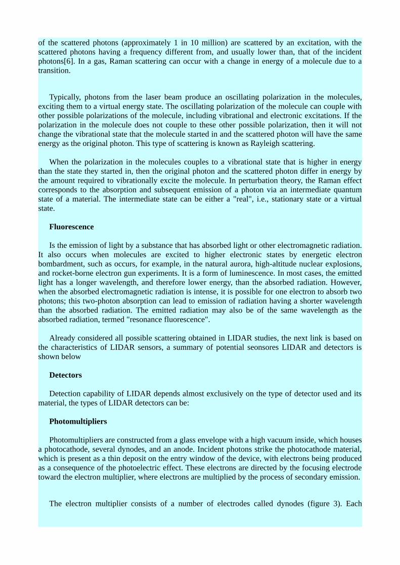
Photomultipliers are constructed from a glass envelope with a high vacuum inside, which houses a photocathode, several dynodes, and an anode. Incident photons strike the photocathode material, which is present as a thin deposit on the entry window of the device, with electrons being produced as a consequence of the photoelectric effect. These electrons are directed by the focusing electrode toward the electron multiplier, where electrons are multiplied by the process of secondary emission.
The electron multiplier consists of a number of electrodes called dynodes (figure 3). Each
dynode is held at a more positive voltage, by ≈100 Volts, than the previous one. A primary electron leaves the photocathode with the energy of the incoming photon, or about 3 eV for "blue" photons, minus the work function of the photocathode. As a group of primary electrons, created by the arrival of a group of initial photons, moves toward the first dynode they are accelerated by the electric field. They each arrive with ≈100 eV kinetic energy imparted by the potential difference. Upon striking the first dynode, more low energy electrons are emitted, and these electrons in turn are accelerated toward the second dynode. The geometry of the dynode chain is such that a cascade occurs with an ever-increasing number of electrons being produced at each stage. For example, if at each stage an average of 4 new electrons are produced for each incoming electron, and if there are 12 dynode stages, then at the last stage one expects for each primary electron about 5^12 ≈ 10^8 electrons. This large number of electrons reaching the last stage, called the anode, results in a sharp current pulse that is easily detectable, signaling the arrival of the photon at the photocathode about a nanosecond earlier.
Figure 3. Photomultiplier Sensor operation
Photo-diode
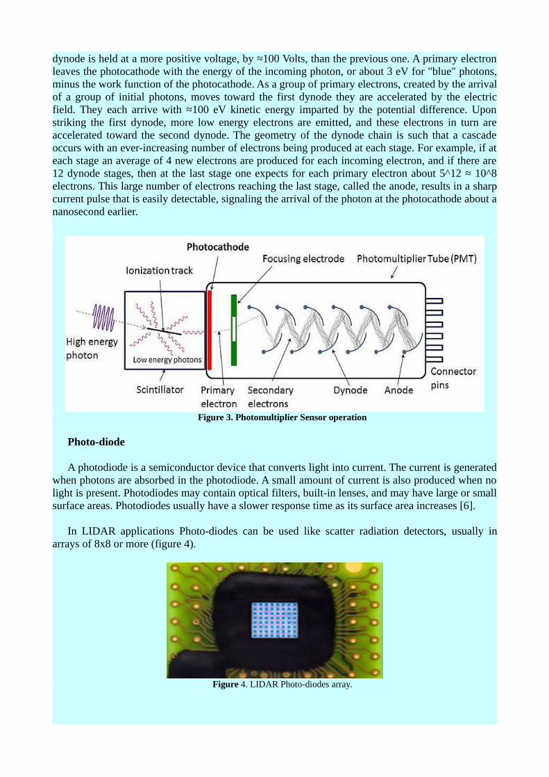
A photodiode is a semiconductor device that converts light into current. The current is generated when photons are absorbed in the photodiode. A small amount of current is also produced when no light is present. Photodiodes may contain optical filters, built-in lenses, and may have large or small surface areas. Photodiodes usually have a slower response time as its surface area increases [6].
In LIDAR applications Photo-diodes can be used like scatter radiation detectors, usually in arrays of 8x8 or more (figure 4).
Figure 4. LIDAR Photo-diodes array.
Solic-Stated Detectors (SSD)
Also called Semiconductor Radiation Detector, radiation detector in which a semiconductor material such as a silicon or germanium crystal constitutes the detecting medium. One such device consists of a p-n junction across which a pulse of current develops when a particle of ionizing radiation traverses it. In a different device, the absorption of ionizing radiation generates pairs of charge carriers (electrons and electron-deficient sites called holes) in a block of semiconducting material; the migration of these carriers under the influence of a voltage maintained between the opposite faces of the block constitutes a pulse of current. The pulses created in this way are amplified, recorded, and analyzed to determine the energy, number, or identity of the incident-charged particles. The sensitivity of these detectors is increased by operating them at low temperatures (commonly that of liquid nitrogen, −164 °C (−263 °F))which suppresses the random formation of charge carriers by thermal vibration[7].
Detection
Although the ability to detect a signal from the beam radiation scattered by the target is important, to discriminate the origin of the signals received by the detector is even more important, countless signals exist in the provenciente environment from all addresses and existing sources, as well as the process of discrimination of the signal is of crucial importance in LIDAR applications, heterodyne detection is the most implemented, a summary of it below
Heterodyne Detection
Is a method of detecting radiation by non-linear mixing with radiation of a reference frequency. It is commonly used in telecommunications and astronomy for detecting and analysing signals.
The radiation in question is most commonly either radio waves or light. The reference radiation is known as the “local oscillator”. The signal and the local oscillator are superimposed at a mixer. The mixer, which is commonly a photo-diode, has a non-linear response to the amplitude, that is, at least part of the output is proportional to the square of the input [8].
The received signal can be represented as:
Esig cos(wsig t +ϕ)
And that of the local oscillator can be represented as:
ELo cos(wLo t )
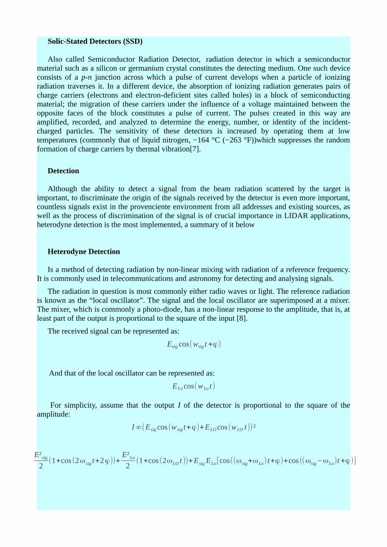
For simplicity, assume that the output I of the detector is proportional to the square of the amplitude:
I ∞(E sig cos (w sig t+ϕ)+ELO cos (wLO t)) ²
E² sig
2(1+cos (2ωsig t+2ϕ))+
E²Lo
2(1+cos (2ωLO t ))+E sig ELo[cos((ωsig+ωLo) t+ϕ)+cos ((ωsig−ωLo)t +ϕ)]
The output has high frequency ( 2ωsig , 2ωLo and ωsig+ωLo ) and constant components. In heterodyne detection, the high frequency components and usually the constant components are filtered out, leaving the intermediate (beat) frequency at . ωsig+ωLo The amplitude of this last component is proportional to the amplitude of the signal radiation. With appropriate signal analysis the phase of the signal can be recovered as well.
If ωLo is equal to ωsig then the beat component is a recovered version of the original signal, with the amplitude equal to the product of Esig and ELo ; that is, the received signal is amplified by mixing with the local oscillator. This is the basis for a Direct conversion receiver.
Design
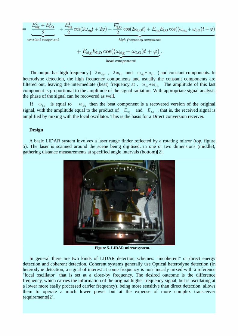
A basic LIDAR system involves a laser range finder reflected by a rotating mirror (top, figure 5). The laser is scanned around the scene being digitised, in one or two dimensions (middle), gathering distance measurements at specified angle intervals (bottom)[2].
Figure 5. LIDAR mirror system.
In general there are two kinds of LIDAR detection schemes: "incoherent" or direct energy detection and coherent detection. Coherent systems generally use Optical heterodyne detection (in heterodyne detection, a signal of interest at some frequency is non-linearly mixed with a reference "local oscillator" that is set at a close-by frequency. The desired outcome is the difference frequency, which carries the information of the original higher frequency signal, but is oscillating at a lower more easily processed carrier frequency), being more sensitive than direct detection, allows them to operate a much lower power but at the expense of more complex transceiver requirements[2].
In both coherent and incoherent LIDAR, there are two types of pulse models: micropulse LIDAR systems and high energy systems. Micropulse systems have developed as a result of the ever increasing amount of computer power available combined with advances in laser technology. They use considerably less energy in the laser, typically on the order of one microjoule, and are often "eye-safe," meaning they can be used without safety precautions. High-power systems are common in atmospheric research, where they are widely used for measuring many atmospheric parameters: the height, layering and densities of clouds, cloud particle properties (extinction coefficient, backscatter coefficient, depolarization), temperature, pressure, wind, humidity, trace gas concentration (ozone, methane, nitrous oxide, etc.)[2].
There are several major components to a LIDAR system:
Laser:
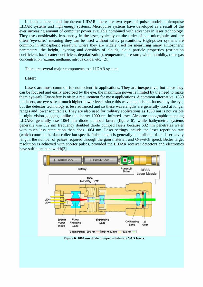
Lasers are most common for non-scientific applications. They are inexpensive, but since they can be focused and easily absorbed by the eye, the maximum power is limited by the need to make them eye-safe. Eye-safety is often a requirement for most applications. A common alternative, 1550 nm lasers, are eye-safe at much higher power levels since this wavelength is not focused by the eye, but the detector technology is less advanced and so these wavelengths are generally used at longer ranges and lower accuracies. They are also used for military applications as 1550 nm is not visible in night vision goggles, unlike the shorter 1000 nm infrared laser. Airborne topographic mapping LIDARs generally use 1064 nm diode pumped lasers (figure 6), while bathymetric systems generally use 532 nm frequency doubled diode pumped lasers because 532 nm penetrates water with much less attenuation than does 1064 nm. Laser settings include the laser repetition rate (which controls the data collection speed). Pulse length is generally an attribute of the laser cavity length, the number of passes required through the gain material, and Q-switch speed. Better target resolution is achieved with shorter pulses, provided the LIDAR receiver detectors and electronics have sufficient bandwidth[2].
Figure 6. 1064 nm diode pumped solid-state YAG lasers.
Scanner and optics:
How fast images can be developed is also affected by the speed at which they are scanned. There are several options to scan the azimuth and elevation, including dual oscillating plane mirrors, a combination with a polygon mirror, a dual axis scanner. Optic choices affect the angular resolution and range that can be detected. A hole mirror or a beam splitter are options to collect a return signal[2].
Photodetector and receiver electronics:
Two main photodetector technologies are used in LIDARs: solid state photodetectors, such as silicon avalanche photodiodes, or photomultipliers. The sensitivity of the receiver is another parameter that has to be balanced in a LIDAR design[2].
Position and navigation systems:
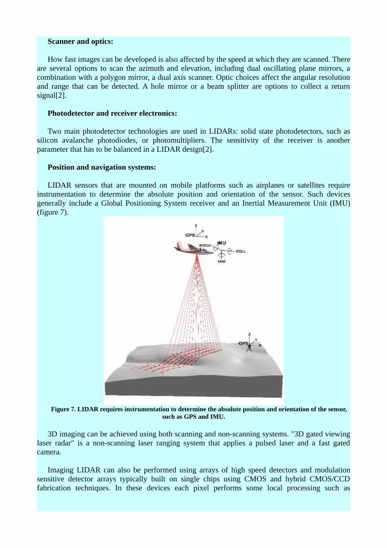
LIDAR sensors that are mounted on mobile platforms such as airplanes or satellites require instrumentation to determine the absolute position and orientation of the sensor. Such devices generally include a Global Positioning System receiver and an Inertial Measurement Unit (IMU) (figure 7).
Figure 7. LIDAR requires instrumentation to determine the absolute position and orientation of the sensor, such as GPS and IMU.
3D imaging can be achieved using both scanning and non-scanning systems. "3D gated viewing laser radar" is a non-scanning laser ranging system that applies a pulsed laser and a fast gated camera.
Imaging LIDAR can also be performed using arrays of high speed detectors and modulation sensitive detector arrays typically built on single chips using CMOS and hybrid CMOS/CCD fabrication techniques. In these devices each pixel performs some local processing such as
demodulation or gating at high speed, downconverting the signals to video rate so that the array may be read like a camera. Using this technique many thousands of pixels/channels may be acquired simultaneously. High resolution 3D LIDAR cameras use homodyne detection with an electronic CCD or CMOS shutter[2].
A coherent Imaging LIDAR uses Synthetic array heterodyne detection to enable a staring single element receiver to act as though it were an imaging array.
Most important Applications
Amongst the most important applications of LIDAR can be mentioned:
Geology and soil science :
High-resolution digital elevation maps generated by airborne and stationary LIDAR have led to significant advances in geomorphology (the branch of geoscience concerned with the origin and evolution of the Earth surface topography). The LIDAR abilities to detect subtle topographic features such as river terraces and river channel banks, to measure the land-surface elevation beneath the vegetation canopy, to better resolve spatial derivatives of elevation, and to detect elevation changes between repeat surveys have enabled many novel studies of the physical and chemical processes that shape landscapes.
In geophysics and tectonics, a combination of aircraft-based LIDAR and GPS has evolved into an important tool for detecting faults and for measuring uplift. The output of the two technologies can produce extremely accurate elevation models for terrain (models that can even measure ground elevation through trees). A satellite-based system, the NASA ICESat, includes a LIDAR sub-system for this purpose. The NASA Airborne Topographic Mapper is also used extensively to monitor glaciers and perform coastal change analysis. The combination is also used by soil scientists while creating a soil survey. The detailed terrain modeling allows soil scientists to see slope changes and landform breaks which indicate patterns in soil spatial relationships.
Atmospheric Remote Sensing and Meteorology :
Initially based on ruby lasers, LIDAR for meteorological applications was constructed shortly after the invention of the laser and represent one of the first applications of laser technology. LIDAR technology has since expanded vastly in capability and LIDAR systems are used to perform a range of measurements that include profiling clouds, measuring winds, studying aerosols and quantifying various atmospheric components. Atmospheric components can in turn provide useful information including surface pressure (by measuring the absorption of oxygen or nitrogen), greenhouse gas emissions (carbon dioxide and methane), photosynthesis (carbon dioxide), fires (carbon monoxide) and humidity (water vapor). Atmospheric LIDARs can be either ground-based, airborne or satellite depending on the type of measurement.
Atmospheric LIDAR remote sensing works in two ways:
1) By measuring backscatter from the atmosphere, and 2) By measuring the scattered reflection off the ground (when the LIDAR is airborne) or other
hard surface.
Backscatter from the atmosphere directly gives a measure of clouds and aerosols. Other derived
measurements from backscatter such as winds or cirrus ice crystals require careful selecting of the wavelength and/or polarization detected. Doppler LIDAR and Rayleigh Doppler LIDAR are used to measure temperature and/or wind speed along the beam by measuring the frequency of the backscattered light. The Doppler broadening of gases in motion allows the determination of properties via the resulting frequency shift. Scanning LIDARs, such as the NASA HARLIE LIDAR, have been used to measure atmospheric wind velocity in a large three-dimensional cone. The ESA wind mission ADM-Aeolus will be equipped with a Doppler LIDAR system in order to provide global measurements of vertical wind profiles. A doppler LIDAR system was used in the 2008 Summer Olympics to measure wind fields during the yacht competition.
Doppler LIDAR systems are also now beginning to be successfully applied in the renewable energy sector to acquire wind speed, turbulence, wind veer and wind shear data. Both pulsed and continuous wave systems are being used. Pulsed systems use signal timing to obtain vertical distance resolution, whereas continuous wave systems rely on detector focusing.
The term eolics has been proposed to describe the collaborative and interdisciplinary study of wind using computational fluid mechanics simulations and Doppler LIDAR measurements.
The ground reflection of an airborne LIDAR gives a measure of surface reflectivity (assuming the atmospheric transmittance is well known) at the LIDAR wavelength. However, the ground reflection is typically used for making absorption measurements of the atmosphere. "Differential absorption LIDAR" (DIAL) measurements utilize two or more closely spaced (<1 nm) wavelengths to factor out surface reflectivity as well as other transmission losses, since these factors are relatively insensitive to wavelength. When tuned to the appropriate absorption lines of a particular gas, DIAL measurements can be used to determine the concentration (mixing ratio) of that particular gas in the atmosphere. This is referred to as an Integrated Path Differential Absorption (IPDA) approach, since it is a measure of the integrated absorption along the entire LIDAR path. IPDA LIDARs can be either pulsed or CW and typically use two or more wavelengths.
Synthetic Array LIDAR allows imaging LIDAR without the need for an array detector. It can be used for imaging Doppler velocimetry, ultra-fast frame rate (MHz) imaging, as well as for speckle reduction in coherent LIDAR. An extensive LIDAR bibliography for atmospheric and hydrospheric applications is given by Grant.
LIDAR speed guns are used by the police to measure the speed of vehicles for speed limit enforcement purposes.
Agriculture :
Agricultural Research Service scientists have developed a way to incorporate LIDAR with yield rates on agricultural fields. This technology will help farmers improve their yields by directing their resources toward the high-yield sections of their land.
LIDAR also can be used to help farmers determine which areas of their fields to apply costly fertilizer. LIDAR can create a topographical map of the fields and reveals the slopes and sun exposure of the farm land. Researchers at the Agricultural Research Service blended this topographical information with the farmland yield results from previous years. From this information, researchers categorized the farm land into high-, medium-, or low-yield zones. This technology is valuable to farmers because it indicates which areas to apply the expensive fertilizers to achieve the highest crop yield[9].
LIDAR software generalities.
In the market there are many tools LIDAR information processing, as is common at present are freely available tools or freewares and tools that are from private sources, some of which are shown below
Free LiDAR Tools
Some freely available tools are:
BCAL LiDAR Tools
BCAL LiDAR Tools are open-source tools developed by Idaho State University, Boise Center Aerospace Laboratory (BCAL). These tools can be used for processing, analyzing and visualizing LiDAR data. They are written in IDL programming language and is intended to be used as add-on in the ENVI remote sensing software package.
FugroViewer
FugroViewer is a freeware designed for use with LiDAR and other raster- and vector-based geospatial datasets, including data from photogrammetric and IFSAR sources.
FUSION /LDV
FUSION is a LIDAR data conversion, analysis, and display software suite. FUSION allows 3-dimensional terrain and canopy surface models and LIDAR data to be fused with more traditional 2-dimensional imagery (e.g., orthophotographs, topographic maps, satellite imagery, GIS shapefiles). FUSION processes raw LIDAR data into a number of vegetation metrics. Canopy- and ground-level surface models can be produced; and then, by simple differing, canopy height models can be generated.
LASTools
LASTools is a collection of command line tools to classify, tile, convert, filter, raster, triangulate, contour, clip, and polygonize LiDAR data (to name just a few functions). All of the tools can also be run via a GUI and are available as a LiDAR processing toolbox for ArcGIS versions 9.3, 10.0, and 10.1 of ESRI.
MCC-LIDAR
MCC-LIDAR is a C++ application for processing LiDAR data in forested environments. It classifies data points as ground or non-ground using the Multiscale Curvature Classification algorithm.
Merrick's Mars Viewer
Free viewing application supports basic LiDAR data navigation and 3D visualization – the perfect tool for casual users.
Online LiDAR viewer
View your point cloud files online in your browser! This web application works locally and does not require data transfers. Supported formats include LAS and XYZ point clouds.
Quick Terrain Reader
The Quick Terrain Reader is the free software for visualizing point clouds and pre-built digital elevation models (DEMs) in a fast and intuitive way.
ENVI LiDAR (non-free)
ENVI LiDAR is an interactive geospatial software environment that lets you create realistic 3D visualizations and easily extract important features and products from raw LiDAR point cloud data. The elevation information contained within LiDAR can be used to create Digital Elevation Models (DEMs), or be included in your geospatial products like line-of-sight or right-of way analyses. ENVI LiDAR can also be customized with the API to meet the unique needs of your organization.
Bibliography
1. James Ring, "The Laser in Astronomy." p. 672-3, New Scientist Jun 20, 1963.2. Cracknell, Arthur P.; Hayes, Ladson (2007) [1991]. Introduction to Remote Sensing (2 ed.).
London: Taylor and Francis. 3. Goyer, G. G.; R. Watson (September 1963). "The Laser and its Application to Meteorology".
Bulletin of the American Meteorological Society. 44 (9): 564–575 [568].4. Barnett, C.E. (1942). "Some application of wavelength turbidimetry in the infrared".
J.Phys.Chem 46 (1): 69–75.5. van de Hulst, H. C. (1957). Light scattering by small particles. New York: John Wiley and
Sons.6. Harris and Bertolucci (1989). Symmetry and Spectroscopy.7. James F. Cox (26 June 2001). Fundamentals of linear electronics: integrated and discrete.
Cengage Learning. pp. 91–8. Britannica Encyclopedia. Solid-state-detector.9. Strauss, Charlie E. M. (1994). "Synthetic-array heterodyne detection: a single-element
detector acts as an array". Optics Letters 19 (20): 1609–1110. "ARS Study Helps Farmers Make Best Use of Fertilizers". USDA Agricultural Research
Service. June 9, 2010.