Embed Size (px)
Citation preview

Nor
th A
mer
ica
Onl
y
Bulletin 71.2:971September 2011
D10
3063
X01
2
www.fisherregulators.com
971 Series Pressure Reducing Regulators
Figure 1. 971 Series Regulators
Features • Control Accuracy—Keeps constant inlet pressures to downstream equipment by accurately controlling system pressures at widely varying flow rates and supply pressures for maximum efficiency and best operation.
• Versatility—A wide variety of applications such as medium to high pressure natural gas transmission and distribution systems, power plants, monitors, and sour gas.
• Easy Adjustment—Easy adjustment of the outlet pressure by simple adjustment of the pilot.
• Tight Shutoff—A combination of soft seat and metal plug with a knife edge provides a long lasting reliable shutoff in normal and erosive service.
• No Atmospheric Bleed—Main regulator loading pressure from pilot bleeds downstream through pilot bleed.
• High Capacity—Body design and flow passage allows exceptionally high capacities with a maximum Cg of 32,500.
• Quiet Operation—Optional noise abatement trim is available for up to 20 dB(A) reduction.
• In-Service Travel Indicator—The travel indicator with protective cover, responds to the precise movement of the diaphragm and plug assembly, and shows the actual valve position.
E0833

Nor
th A
mer
ica
Onl
y
Bulletin 71.2:971
2
Available Configurations Type 971: Pilot-operated pressure reducing regulator for medium to high outlet pressures Type 971-E: Monitor version installed upstream or downstream of the working regulator for overpressure protection
Body Size and End Connection Style NPS 10 / DN 250 body with CL300 or CL600 RF Flanges
Main Valve End Connection Style and Pressure Ratings(1)
CL300 RF: 740 psig / 51,0 bar CL600 RF: 1450 psig / 100 bar
Maximum Inlet and Outlet (Casing) Pressure(1)
1450 psig / 100 bar
Maximum Outlet (Casing) Pressure(1)
1015 psig / 70,0 barMinimum Operating Differential Pressure Start Open: 7.3 psid / 0,50 bar d Full Open: 14.5 psid / 1,00 bar d
Maximum Emergency (Design Pressure) 1450 psig / 100 bar
Outlet Pressure Ranges See Table 1
Flow Coefficients Regulating–Cg: 32 500; Cv: 1048 Wide-Open–Cg: 32 500; Cv: 1048 C1: 31
Specifications
Pilot Flow Coefficients Cg: 10.5; Cv: 0.36; C1: 29
Pressure Registration External
Temperature Capabilities(1)
Standard Version: Working: 14° to 140°F / -10° to 60°C Low Temperature Version: Working: -4° to 140°F / -20° to 60°C
Construction Materials 971 Series Main Valve Main Body: A216 WCB Steel Actuator Tops: Steel, Fe 42 UNI 7070 Diaphragm Plates: Steel Stem and Valve Seat: Stainless steel, X30 Cr 13 UNI 6901 Piston: Steel, Fe 37 UNI 7070 Diaphragm and Seat: Nitrile (NBR) or Fluorocarbon (FKM) Type PRX Pilot Body: Steel, ASTM 105 Trim: Stainless steel Elastomers: Nitrile (NBR) or Fluorocarbon (FKM) Disk: Polyurethane (PUR) Type SA/2 Supply Pressure Regulator Body: Steel Diaphragm: Nitrile (NBR) with PVC coating O-ring and Disk: Nitrile (NBR) or Fluorocarbon (FKM)
Approximate Weight (Including Pilot) 3748 pounds / 1700 kg
1. The pressure/temperature limits in this Bulletin or any applicable standard limitation should not be exceeded.
IntroductionThe 971 Series regulators are accurate pilot-operated, pressure balanced, soft seated regulators designed for high-pressure transmission/city gate, large capacity distribution systems and power plant feeds. The 971 Series provides smooth, quiet operation, tight shutoff and long life. The regulator utilizes a main valve actuator, a Type PRX pressure reducing pilot, and a Type SA/2 pilot supply pressure regulator. The Type PRX pilot uses inlet pressure reduced by a Type SA/2 supply pressure regulator, as loading pressure to operate the main valve actuator. The outlet pressure is sensed through a control line on the main valve actuator and also on the Type PRX pilot diaphragm.
The superior performance of the Type 971 is due to the amplifying effect of the pilot and two-path control system. Changes in outlet pressure act quickly on the actuator diaphragm to provide fast response to system change. The pilot amplifies any small system changes to position the main valve for precise pressure control.
Type PRX Pilot Type DescriptionsA pressure reducing pilot that has the ability to handle a wide range of setpoints from 14.5 to 1160 psig / 1,00 to 80,0 bar in two versions:

Nor
th A
mer
ica
Onl
y
Bulletin 71.2:971
3
Type PRX/120: A pressure reducing pilot with an outlet pressure range of 14.5 to 435 psig / 1,00 to 30,0 bar. The Type PRX/120 can be used as the pilot on single stage pressure reducing regulators or as the monitor pilot or as the working pilot in wide-open monitor systems.Type PRX/120-AP: A pressure-reducing pilot with an outlet pressure range of 435 to 1160 psig / 30,0 to 80,0 bar. The Type PRX/120-AP can be used as the pilot on single stage pressure reducing regulators or as the monitor pilot or as the working pilot in wide-open monitor systems.Type PRX/125: This pilot is identical to the Type PRX/120 except that the restriction screw is removed. The Type PRX/125 can only be used as the monitor override pilot on working monitor applications. The pilot has an outlet pressure range of 14.5 to 435 psig / 1,00 to 30,0 bar.Type PRX/125-AP: This pilot is identical to the Type PRX/120-AP except that the restriction screw is removed. The Type PRX/125-AP can only be used as the monitor override pilot on working monitor applications. The pilot has an outlet pressure range of 435 to 1160 psig / 30,0 to 80,0 bar.
Pilot Supply RegulatorThe Type SA/2 pilot supply filter regulator, provides a constant supply pressure to the Type PRX pilot that is 45 psig / 3,1 bar over set pressure. The Type SA/2 has an integral 5 micron filter.
Noise AbatementThe Type SR high velocity (up to 262 ft/s / 80 m/s at the outlet flange) noise abatement device is incorporated into the regulator on the downstream side and consists of plated stainless steel wires containing no sound deadening materials. Depending on flows and pressure drop, the silencer can reduce noise levels as much as 20 dB(A) with an approximate 8% Cg reduction.
Table 1. Outlet Pressure Ranges
TYPESOUTLET PRESSURE RANGE SPRING
COLORSPRING PART
NUMBERpsig bar
PRX/120PRX/125
14.5 to 2623 to 4441 to 8073 to 123
1,00 to 1,81,6 to 3,02,8 to 5,55,0 to 8,5
YellowGreenBlueBlack
GD25524X012GD25523X012GD25518x012GD25522X012
116 to 210203 to 334319 to 435
8,0 to 14,514,0 to 23,022,0 to 30,0
SilverGold
Aluminum
GD25521X012GD25520X012GD25586X012
PRX/120-APPRX/125-AP 435 to 1160 30,0 to 80,0 Clear GD27379X012
1. The Type 971 is limited to 1015 psig (70,0 bar) downstream pressure.
Principle of Operation The pilot-operated Type 971 (Figure 2) uses inlet pressure as the operating medium, which is reduced through pilot operation to load the actuator diaphragm. Outlet or downstream pressure opposes loading pressure in the actuator and also opposes the pilot control spring.When outlet pressure drops below the setting of the pilot control spring, pilot control spring force on the pilot diaphragm thus opens the pilot valve plug, providing additional loading pressure to the actuator diaphragm. This diaphragm loading pressure opens the main valve plug, supplying the required flow to the downstream system. Any excess loading pressure on the actuator diaphragm escapes downstream through the bleed restriction in the pilot.When the gas demand in the downstream system has been satisfied, the outlet pressure increases. The increased pressure is transmitted through the downstream control line and acts on the pilot diaphragm. This pressure exceeds the pilot spring setting and moves the diaphragm, closing the orifice. The loading pressure acting on the main diaphragm bleeds to the downstream system through a bleed restriction in the pilot.
AdjustmentThe adjustment of the regulator is performed by means of the pilot adjusting screw, which varies the compression of the control spring. Adjustment is performed while the regulator is in operation with the aid of a test pressure gauge of suitable range or of a water column. The shut-off valve downstream of the regulator must not be completely closed; it is necessary that a small quantity of gas flows downstream to allow the outlet side to vent down, when it is necessary to lower the pressure. Loosen the locknut and turn the adjusting screw slowly to adjust outlet pressure. Use a pressure gauge to check the outlet pressure until the desired pressure is reached.

Nor
th A
mer
ica
Onl
y
Bulletin 71.2:971
4
Monitoring Systems Monitoring regulation is overpressure protection by containment, therefore, there is no relief valve to vent to the atmosphere. When the working regulator fails to control the pressure, a monitor regulator installed in series, which has been sensing the downstream and control pressure, goes into operation to maintain the downstream pressure at a slightly higher than normal pressure. During an overpressure situation, monitoring keeps the customer on line. Also, testing is relatively easy and safe. To perform a periodic test on a monitoring regulator, increase the outlet set pressure of the working regulator and watch the outlet pressure to determine if the monitoring regulator takes over at the appropriate outlet pressure.
Wide-Open Monitoring Systems (Figure 3)There are two types of wide-open monitoring systems: upstream and downstream. The difference between upstream and downstream monitoring is that the functions of the regulators are reversed. Systems can be changed from upstream to downstream monitoring, and vice versa, by simply reversing the setpoints of the two regulators. The decision to use either an upstream or downstream monitoring system is largely a matter of personal preference or company policy.In normal operation of a wide-open configuration, the working regulator controls the system’s outlet
pressure. With a higher outlet pressure setting, the monitor regulator senses a pressure lower than its setpoint and tries to increase outlet pressure by going wide open. If the working regulator fails, the monitoring regulator assumes control and holds the outlet pressure at its outlet pressure setting.
Working Monitoring Regulators (Figure 3)In a working monitoring system, the upstream regulator requires two pilots and it is always the monitoring regulator. The additional pilot permits the monitoring regulator to act as a series regulator to control an intermediate pressure during normal operation. In this way, both units are always operating and can be easily checked for proper operation. In normal operation, the working regulator controls the outlet pressure of the system. The monitoring regulator’s working pilot controls the intermediate pressure and the monitoring pilot senses the system’s outlet pressure. If the working regulator fails, the monitoring pilot will sense the increase in outlet pressure and take control.
Note
The working regulator must be rated for the maximum allowable operating pressure of the system because this will be its inlet pressure if the monitoring
Figure 2. Type 971 Operational Schematic
TYPEPRX
TYPESA/2
V
RM
S
L A
B
E0835
TYPEPRX
TYPESA/2
INLET PRESSUREOUTLET PRESSUREATMOSPHERIC PRESSURELOADING PRESSUREPILOT SUPPLY PRESSURE

Nor
th A
mer
ica
Onl
y
Bulletin 71.2:971
5
Figure 3. Typical 971 Installation Schematics
E0836
MONITOR REGULATOR
WORKING REGULATOR
4 x A
6 x A
A
TYPE SA/2
TYPE SA/2
TYPE PRX/125 OR PRX/125-AP TYPE PRX/120
OR PRX/120-APTYPE PRX/120 OR PRX/120-AP
6 x A
4 x A
A
TYPE SA/2
TYPE PRX/120 OR PRX/120-AP
TYPE PRX/120 OR PRX/120-AP
6 x A
4 x A
TYPE SA/2
SINGLE PILOT SYSTEM INSTALLATION
UPSTREAM OR DOWNSTREAM WIDE-OPEN MONITORING SYSTEM INSTALLATION
WORKING MONITORING SYSTEM INSTALLATION
TYPE PRX/120 OR PRX/120-AP
A
B
B
B B BL L L
S S S
A A A
BL L
S S
A A
SL
A
Nor
th A
mer
ica
Onl
y
Bulletin 71.2:971
6
regulator fails. Also, the outlet pressure rating of the monitoring pilot and any other components that are exposed to the intermediate pressure must be rated for full inlet pressure.
Working monitor installations require a Type 971 main valve with a Type PRX/120 or PRX/120-AP working pilot and a Type PRX/125 or PRX/125-AP monitoring pilot for the upstream regulator and a Type 971 with the appropriate Type PRX/120 or PRX/120-AP pilot for the downstream regulator.
AdjustmentAdjusting the monitor regulator is similar to adjusting the main regulator. Monitor setpoints are set slightly higher than the main regulator. However, the value of this difference cannot be determined in advance, as it depends on the particular characteristics of each application.
Capacity InformationTo fi nd approximate regulating capacities or to fi nd wide-open fl ow capacities for relief sizing at any inlet pressure, perform one of the following procedures. Then, if necessary, convert using the factors provided below.For critical pressure drops (absolute outlet pressure equal to or less than one-half of absolute inlet pressure), use the following formula:
Q = (P1)(Cg)(1.29)
For pressure drops lower than critical (absolute outlet pressure greater than one-half of absolute inlet pressure).
Q = CgP1SIN DEG520GT ) )P1
P3417C1
where,
Q = gas fl ow rate, SCFH P1 = absolute inlet pressure, psia (P1 gauge + 14.7) Cg = regulating or wide-open gas sizing coeffi cient from the Specifi cations section G = gas specifi c gravity of the gas T = absolute temperature of gas at inlet, °Rankine C1 = fl ow coeffi cient P = pressure drop across the regulator, psi
To determine equivalent capacities for air, propane, butane, or nitrogen, multiply the capacity by the following appropriate conversion factor: 0.775 for air, 0.628 for propane, 0.548 for butane, or 0.789 for nitrogen. For gases of other specifi c gravities, multiply the given capacity by 0.775, and divide by the square root of the appropriate specifi c gravity. Then, if capacity is desired in normal cubic meters per hour at 0°C and 1,01325 bar, multiply SCFH by 0.0268.
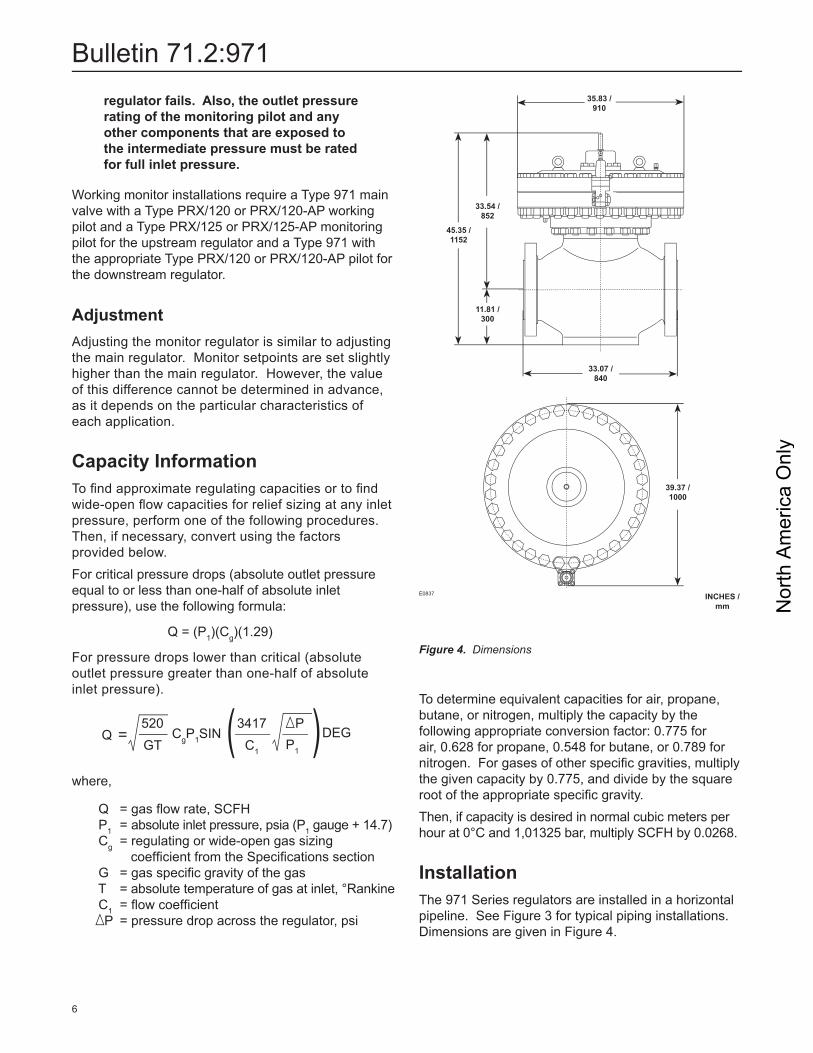
InstallationThe 971 Series regulators are installed in a horizontal pipeline. See Figure 3 for typical piping installations. Dimensions are given in Figure 4.
Figure 4. Dimensions
E0837 INCHES /mm
39.37 /1000
45.35 / 1152
11.81 / 300
33.54 /852
35.83 /910
33.07 /840

Nor
th A
mer
ica
Onl
y
Bulletin 71.2:971
7
Ordering GuideType (Select One)
971** 971E**
End Connection Style (Select One) CL300 RF**
CL600 RF**
O-Ring Material (Select One) Nitrile (NBR) (standard)** Fluorocarbon (FKM)**
Pilot Type (Select One) PRX-120**
PRX/120-AP** PRX-125 (monitor override pilot)** PRX-AP/125-AP (monitor override pilot)**
Outlet Pressure Range (Select One)Type PRX-120/125
14.5 to 26 psig / 1,00 to 1,8 bar, Yellow** 23 to 44 psig / 1,6 to 3,0 bar, Green** 41 to 80 psig / 2,8 to 5,5 bar, Blue** 73 to 123 psig / 5,0 to 8,5 bar, Black** 116 to 210 psig / 8,0 to 14,5 bar, Silver** 203 to 334 psig / 14,0 to 23,0 bar, Gold** 319 to 435 psig / 22,0 to 30,0 bar, Aluminum**
Type PRX-AP-120/125 435 to 1160 psig / 30,0 to 80,0 bar, Clear**
Silencer (Optional) Type SR** None
Pilot Diaphragm and Valve Disk Assembly (Select One) Nitrile (NBR) (standard)** Fluorocarbon (FKM)**
Type SA/2 O-Ring and Seat Material Nitrile (NBR) (standard)** Fluorocarbon (FKM)**
Pilot Valve Replacement Parts Kit (Optional) Yes, send one replacement parts kit to match
this order.
Regulators Quick Order Guide* * * Standard - Readily Available for Shipment
* * Non-Standard - Allow Additional Time for Shipment
* Special Order, Constructed from Non-Stocked Parts. Consult your local Sales Offi ce for Availability.
Availability of the product being ordered is determined by the component with the longest shipping time for the requested construction.
Specifi cation WorksheetApplication:Specifi c UseLine SizeFluid TypeSpecifi c GravityTemperatureDoes the Application Require Overpressure Protection? Yes No
Pressure:Maximum Inlet PressureMinimum Inlet PressureDifferential PressureSet PressureMaximum Flow
Accuracy Requirements:Less Than or Equal To: 5% 10% 20% 40%
Construction Material Requirements (if known):
Ordering InformationCarefully review each specifi cation in the Specifi cations section, then complete the Specifi cation Worksheet below. If a pilot setpoint is not requested, the regulator will be set at the approximate midrange.

Nor
th A
mer
ica
Onl
y
Bulletin 71.2:971
The Emerson logo is a trademark and service mark of Emerson Electric Co. All other marks are the property of their prospective owners. Fisher is a mark owned by Fisher Controls, Inc., a business of Emerson Process Management.
The contents of this publication are presented for informational purposes only, and while every effort has been made to ensure their accuracy, they are not to be construed as warranties or guarantees, express or implied, regarding the products or services described herein or their use or applicability. We reserve the right to modify or improve the designs or specifications of such products at any time without notice.
Emerson Process Management does not assume responsibility for the selection, use or maintenance of any product. Responsibility for proper selection, use and maintenance of any Emerson Process Management product remains solely with the purchaser.
Industrial Regulators
Emerson Process Management Regulator Technologies, Inc.
USA - HeadquartersMcKinney, Texas 75069-1872, USATel: +1 800 558 5853Outside U.S. +1 972 548 3574
Asia-PacificShanghai 201206, ChinaTel: +86 21 2892 9000
EuropeBologna 40013, ItalyTel: +39 051 419 0611
Middle East and AfricaDubai, United Arab EmiratesTel: +971 4811 8100
Natural Gas Technologies
Emerson Process ManagementRegulator Technologies, Inc.
USA - HeadquartersMcKinney, Texas 75069-1872, USATel: +1 800 558 5853Outside U.S. +1 972 548 3574
Asia-PacificSingapore 128461, SingaporeTel: +65 6770 8337
EuropeBologna 40013, ItalyTel: +39 051 419 0611Gallardon 28320, FranceTel: +33 2 37 33 47 00
TESCOM
Emerson Process ManagementTescom Corporation
USA - HeadquartersElk River, Minnesota 55330-2445, USATels: +1 763 241 3238 +1 800 447 1250
EuropeSelmsdorf 23923, GermanyTel: +49 38823 31 287
Asia-PacificShanghai 201206, ChinaTel: +86 21 2892 9499
For further information visit www.fisherregulators.com
©Emerson Process Management Regulator Technologies, Inc., 2002, 2011; All Rights Reserved