Embed Size (px)
Citation preview
SERIE G50
SOLLEVATORI ELETTROIDRAULICI A DUE COLONNETWO COLUMN ELECTRO-HYDRAULIC LIFTSELEKTROHYDRAULISCHE HEBEBÜNEELEVADORES ELECTROHIDRAULICOS DE DOS COLUMNAS
INSTALLAZIONE, USO, MANUTENZIONE E RICAMBIINSTALLATION, USE, MAINTENANCE AND SPARE PARTS
INSTALLATION, GEBRAUCH, WARTUNG UND ERSATZTEILEINSTALACIÓN, USO, MANTENIMIENTO Y REPUESTOS
2
Il presente libretto istruzione è redatto nella lingua del costruttore e in altre lingue comunitarie.In caso di contestazione, incidente, o quant’altro, ai fini giuridici fa testo esclusivamente la versione in lingua italiana.La AGM-COSMET declina ogni e qualsiasi responsabilità per danni diretti e/o indiretti cagionati da cattiva traduzione o errata interpretazione del testo tradotto.
This instruction manual is drawn up in the language of the manufacturer and in other European languages.If there is a dispute, accident or anything else, the Italian language version of this manual will be exclusively used for legal purposes.AGM-COSMET declines all and any responsibility for direct or indirect damage caused by poor translation or erroneous interpretation of the translated text.
El presente manual de instrucciones está redactado en el idioma del constructor y en otras lenguas comunitarias .En caso de contestación, impugnación, accidente, y/o cualquier otro inconveniente, a los fines jurídicos se considera válido el texto en la versión en lengua italiana exclusivamente .La AGM-COSMET declina toda y / ó cualquier responsabilidad por daños directos y / o indirectos ocasionados por una mala traducción ó por una interpretación equivocada del texto traducido .
Das vorliegende Handbuch wurde in der Muttersprache des Herstellers und in weiteren Sprachen der Europäischen verfasst.Im Falle von Beanstandungen, Unfällen usw. ist zu juristischen Zwecken ausschließlich die Version in italienischer Sprache maßgeblich.Das Unternehmen AGM-COSMET lehnt jegliche Haftung für direkte und/oder indirekte Schäden ab, die durch schlechte Übersetzung oder falsche Auslegung des übersetzten Textes entstehen.
3
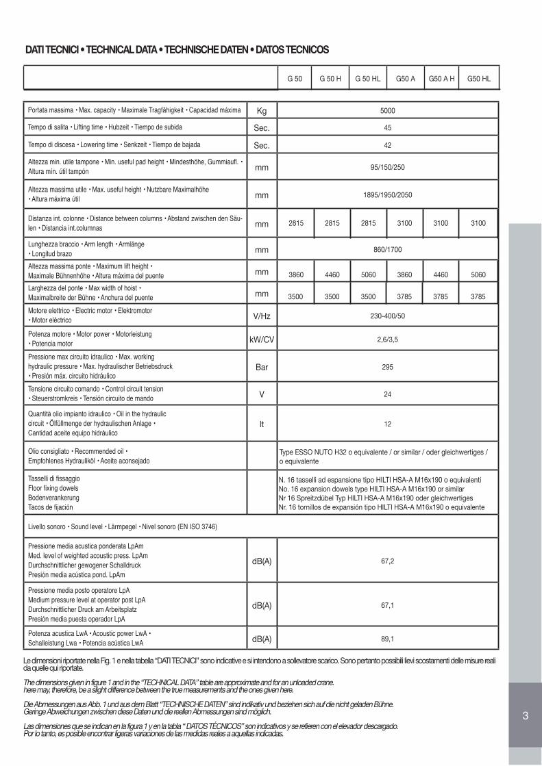
DATI TECNICI • TECHNICAL DATA • TECHNISCHE DATEN • DATOS TECNICOS
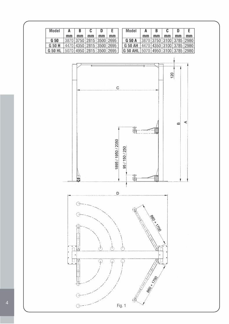
Le dimensioni riportate nella Fig. 1 e nella tabella “DATI TECNICI” sono indicative e si intendono a sollevatore scarico. Sono pertanto possibili lievi scostamenti delle misure reali da quelle qui riportate.
The dimensions given in figure 1 and in the “TECHNICAL DATA” table are approximate and for an unloaded crane. here may, therefore, be a slight difference between the true measurements and the ones given here.
Die Abmessungen aus Abb. 1 und aus dem Blatt “TECHNISCHE DATEN” sind indikativ und beziehen sich auf die nicht geladen Bühne.Geringe Abweichungen zwischen diese Daten und die reellen Abmessungen sind möglich.
Las dimensiones que se indican en la figura 1 y en la tabla “ DATOS TÉCNICOS” son indicativos y se refieren con el elevador descargado.Por lo tanto, es posible encontrar ligeras variaciones de las medidas reales a aquellas indicadas.
Portata massima • Max. capacity • Maximale Tragfähigkeit • Capacidad máxima Kg 5000
Tempo di salita • Lifting time • Hubzeit • Tiempo de subida Sec. 45
Tempo di discesa • Lowering time • Senkzeit • Tiempo de bajada Sec. 42
Altezza min. utile tampone • Min. useful pad height • Mindesthöhe, Gummiaufl. • Altura mín. útil tampón mm 95/150/250
Altezza massima utile • Max. useful height • Nutzbare Maximalhöhe• Altura máxima útil mm 1895/1950/2050
Distanza int. colonne • Distance between columns • Abstand zwischen den Säu-len • Distancia int.columnas mm
Lunghezza braccio • Arm length • Armlänge• Longitud brazo mm 860/1700
Altezza massima ponte • Maximum lift height •Maximale Bühnenhöhe • Altura máxima del puente mm
Larghezza del ponte • Max width of hoist •Maximalbreite der Bühne • Anchura del puente mm
Motore elettrico • Electric motor • Elektromotor• Motor eléctrico V/Hz 230-400/50
Potenza motore • Motor power • Motorleistung• Potencia motor kW/CV 2,6/3,5
Pressione max circuito idraulico • Max. workinghydraulic pressure • Max. hydraulischer Betriebsdruck• Presión máx. circuito hidráulico
Bar 295
Tensione circuito comando • Control circuit tension• Steuerstromkreis • Tensión circuito de mando V 24
Quantità olio impianto idraulico • Oil in the hydrauliccircuit • Ölfüllmenge der hydraulischen Anlage •Cantidad aceite equipo hidráulico
lt 12
Olio consigliato • Recommended oil •Empfohlenes Hydrauliköl • Aceite aconsejado
Type ESSO NUTO H32 o equivalente / or similar / oder gleichwertiges / o equivalente
Tasselli di fissaggioFloor fixing dowelsBodenverankerungTacos de fijación
N. 16 tasselli ad espansione tipo HILTI HSA-A M16x190 o equivalentiNo. 16 expansion dowels type HILTI HSA-A M16x190 or similarNr 16 Spreitzdübel Typ HILTI HSA-A M16x190 oder gleichwertigesNr. 16 tornillos de expansión tipo HILTI HSA-A M16x190 o equivalente
Livello sonoro • Sound level • Lärmpegel • Nivel sonoro (EN ISO 3746)
Pressione media acustica ponderata LpAmMed. level of weighted acoustic press. LpAmDurchschnittlicher gewogener SchalldruckPresión media acústica pond. LpAm
dB(A) 67,2
Pressione media posto operatore LpAMedium pressure level at operator post LpADurchschnittlicher Druck am ArbeitsplatzPresión media puesta operador LpA
dB(A) 67,1
Potenza acustica LwA • Acoustic power LwA •Schalleistung Lwa • Potencia acústica LwA dB(A) 89,1
G 50 G 50 H G 50 HL G50 A G50 A H G50 HL
2815 2815 2815 3100 3100 3100
3860 4460 5060 3860 4460 5060
3500 3500 3500 3785 3785 3785
4
5
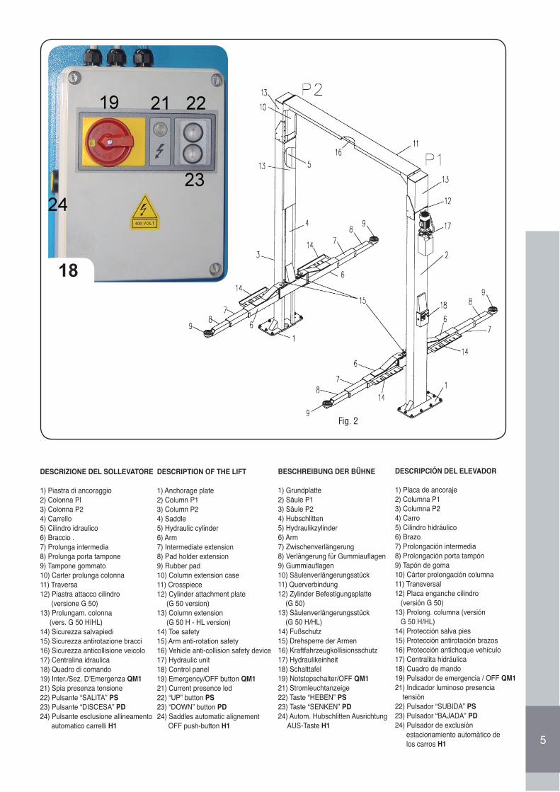
DESCRIZIONE DEL SOLLEVATORE
1) Piastra di ancoraggio2) Colonna Pl3) Colonna P24) Carrello5) Cilindro idraulico6) Braccio .7) Prolunga intermedia8) Prolunga porta tampone9) Tampone gommato10) Carter prolunga colonna11) Traversa12) Piastra attacco cilindro (versione G 50)13) Prolungam. colonna (vers. G 50 HIHL)14) Sicurezza salvapiedi15) Sicurezza antirotazione bracci16) Sicurezza anticollisione veicolo17) Centralina idraulica18) Quadro di comando19) Inter./Sez. D’Emergenza QM121) Spia presenza tensione22) Pulsante “SALITA” PS23) Pulsante “DISCESA” PD24) Pulsante esclusione allineamento automatico carrelli H1
DESCRIPTION OF THE LIFT
1) Anchorage plate2) Column P13) Column P24) Saddle5) Hydraulic cylinder6) Arm7) Intermediate extension8) Pad holder extension9) Rubber pad10) Column extension case11) Crosspiece12) Cylinder attachment plate (G 50 version)13) Column extension (G 50 H - HL version)14) Toe safety15) Arm anti-rotation safety16) Vehicle anti-collision safety device17) Hydraulic unit18) Control panel19) Emergency/OFF button QM121) Current presence led 22) “UP” button PS23) “DOWN” button PD24) Saddles automatic alignement OFF push-button H1
BESCHREIBUNG DER BÜHNE
1) Grundplatte2) Säule P13) Säule P24) Hubschlitten5) Hydraulikzylinder6) Arm7) Zwischenverlängerung8) Verlängerung für Gummiauflagen9) Gummiauflagen10) Säulenverlängerungsstück11) Querverbindung12) Zylinder Befestigungsplatte (G 50)13) Säulenverlängerungsstück (G 50 H/HL)14) Fußschutz15) Drehsperre der Armen16) Kraftfahrzeugkollisionsschutz17) Hydraulikeinheit18) Schalttafel19) Notstopschalter/OFF QM121) Stromleuchtanzeige22) Taste “HEBEN” PS23) Taste “SENKEN” PD24) Autom. Hubschlitten Ausrichtung AUS-Taste H1
DESCRIPCIÓN DEL ELEVADOR
1) Placa de ancoraje2) Columna P13) Columna P24) Carro5) Cilindro hidráulico6) Brazo7) Prolongación intermedia8) Prolongación porta tampón9) Tapón de goma10) Cárter prolongación columna11) Transversal12) Placa enganche cilindro (versión G 50)13) Prolong. columna (versión G 50 H/HL)14) Protección salva pies15) Protección antirotación brazos16) Protección antichoque vehículo17) Centralita hidráulica18) Cuadro de mando19) Pulsador de emergencia / OFF QM121) Indicador luminoso presencia tensión22) Pulsador “SUBIDA” PS23) Pulsador “BAJADA” PD 24) Pulsador de exclusión estacionamiento automàtico de los carros H1
18
6
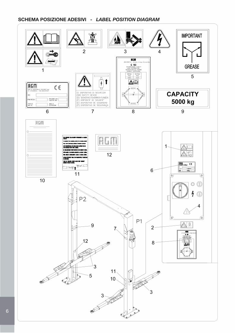
SCHEMA POSIZIONE ADESIVI - LABEL POSITION DIAGRAM
7
828
9
Fig. 11
10 12
11
12
ITAL
IANO
INDICE
PRIMA DI INIZIARE AD OPERARE CON IL PONTE LEGGERE ATTENTAMENTE LE ISTRUZIONICONTENUTE NEL PRESENTE MANUALE
1.0 PREMESSA..................................................................................................................................................................................................... 131.1 GARANZIA ..................................................................................................................................................................................................... 131.1.1 Esclusioni dalla garanzia................................................................................................................................................................................ 131.2 LA CERTIFICAZIONE CE .............................................................................................................................................................................. 131.3 DESTINAZIONE D’USO ................................................................................................................................................................................. 141.4 IDENTIFICAZIONE DEL SOLLEVATORE....................................................................................................................................................... 142.0 NORME GENERALI DI SICUREZZA E PREVENZIONE INFORTUNI............................................................................................................ 142.1 LIVELLI DI PERICOLO ................................................................................................................................................................................... 142.2 SEGNALI DI AVVERTIMENTO ....................................................................................................................................................................... 152.3 ABBIGLIAMENTO........................................................................................................................................................................................... 152.4 ECOLOGIA E INQUINAMENTO .................................................................................................................................................................... 152.4.1 Demolizione del sollevatore ............................................................................................................................................................................ 152.5 USO IN SICUREZZA...................................................................................................................................................................................... 152.6 MANUTENZIONE IN SICUREZZA ................................................................................................................................................................. 163.0 MOVIMENTAZIONE E INSTALLAZIONE........................................................................................................................................................ 173.1 TRASPORTO E SCARICO............................................................................................................................................................................. 173.2 INSTALLAZIONE ............................................................................................................................................................................................ 173.3 FONDAZIONI.................................................................................................................................................................................................. 173.4 POSIZIONAMENTO ED INSTALLAZIONE DELLA STRUTTURA ................................................................................................................. 173.4.1 POSIZIONAMENTO DELLE COLONNE E TRAVERSA................................................................................................................................. 173.4.2 COLLEGAMENTI OLEODINAMICI ................................................................................................................................................................ 183.4.3 COLLEGAMENTI ALLA RETE ELETTRICA ................................................................................................................................................... 183.4.4 RIEMPIMENTO IMPIANTO OLEODINAMICO ............................................................................................................................................... 193.4.5 ALLINEAMENTO CARRELLI.......................................................................................................................................................................... 193.4.5.1 ALLINEAMENTO CARRELL ALLA MESSA IN SERVIZIO ............................................................................................................................. 193.4.5.2 ALLINEAMENTO CARRELLI IN ESERCIZIO................................................................................................................................................. 193.4.6 APPLICAZIONE TARGHETTE ADESIVE E PITTOGRAMMI ........................................................................................................................ 204.0 ISTRUZIONI PER L’USO................................................................................................................................................................................ 204.1 PULSANTIERA............................................................................................................................................................................................... 204.1.1 Salita sollevatore ............................................................................................................................................................................................ 204.1.2 Discesa sollevatore......................................................................................................................................................................................... 204.1.3 Pulsante di emergenza/OFF............................................................................................................................................................................ 214.1.4 Pulsante di ripristino/ON ................................................................................................................................................................................. 214.1.5 Spia presenza tensione .................................................................................................................................................................................. 214.2 PROCEDURA DI SOLLEVAMENTO............................................................................................................................................................... 214.3 PROCEDURA PER LA DISCESA................................................................................................................................................................... 224.4 DISPOSITIVI DI SICUREZZA..........................................................................................................................................................................224.5 DISCESA DI EMERGENZA ............................................................................................................................................................................ 225.0 MANUTENZIONE ........................................................................................................................................................................................... 235.1 VERIFICA DEI DISPOSITIVI DI SICUREZZA ................................................................................................................................................ 235.1.1 Spia presenza tensione .................................................................................................................................................................................. 235.1.2 Sicurezze meccaniche di stazionamento carrelli ............................................................................................................................................ 235.1.3 Sicurezze contro il disallineamento dei carrelli .............................................................................................................................................. 235.1.4 Tamponi con riporto in gomma ....................................................................................................................................................................... 235.1.5 Pulsante di emergenza/OFF .......................................................................................................................................................................... 235.2 MANUTENZIONE PERIODICA ...................................................................................................................................................................... 245.2.1 Ogni settimana ............................................................................................................................................................................................... 245.2.2 Ogni mese ...................................................................................................................................................................................................... 245.2.3 Ogni 200 ore di funzionamento ...................................................................................................................................................................... 245.3 POMPA IDRAULICA........................................................................................................................................................................................ 246.0 RICERCA GUASTI ED INCONVENIENTI ...................................................................................................................................................... 257.0 PARTI DI RICAMBIO...................................................................................................................................................................................... 257.1 SISTEMA OLEODINAMICO .......................................................................................................................................................................... 687.2 SCHEMA CIRCUITO ELETTRICO DI POTENZA........................................................................................................................................... 697.3 SCHEMA CIRCUITO ELETTRICO DI POTENZA........................................................................................................................................... 707.4 SCHEMA CIRCUITO ELETTRICO DI POTENZA........................................................................................................................................... 717.5 SCHEMA CIRCUITO ELETTRICO DI COMANDO......................................................................................................................................... 727.6 SCHEMA POSIZIONE COMPONENTI .......................................................................................................................................................... 73
Tav. I ............................................................................................................................................................................................................... 74Tav. II............................................................................................................................................................................................................... 76Tav. III.............................................................................................................................................................................................................. 78Tav. IV.............................................................................................................................................................................................................. 80Tav. V............................................................................................................................................................................................................... 82Tav. VI-VII ....................................................................................................................................................................................................... 84 RISERVATO AL TECNICO INSTALLATORE................................................................................................................................................... 86
13
ITAL
IANO
1.2 LA CERTIFICAZIONE CE
La Direttiva 98137/CE conosciuta comunemente come “Direttiva Macchine”, precisa le condizioni con le quali una macchina può essere immessa nel mercato. Detta Direttiva prescrive che tutte le macchine possono essere commercializzate e messe in servizio soltanto se non pregiudicano la sicurezza e la salute delle persone, degli animali domestici o dei beni. Per attestare la conformità del sollevatore alle disposizioni della Direttiva la AGM-COS.MET, prima della commer-cializzazione, ha sottoposto all’esame di un organismo notificato un esemplare della macchina. Il sollevatore, costruito in conformità alle disposizioni contenute nella direttiva 98137/CE ha superato l’esame effettuato e può quindi essere immesso sul mercato senza pregiudicare la sicurezza dell’utilizzatore.Il sollevatore, viene quindi consegnato al cliente dotato ed accompagnato di:
• Dichiarazione CE di conformità• Marchiatura CE• Libretto Istruzione per l’UsoIl sollevatore non è atto al sollevamento di persone
1.0 PREMESSA
Questo manuale riporta le istruzioni per l’installazione, l’uso e la manutenzione dell’impianto di sollevamento denominato “SOLLEVATORE ELETTROIDRAULICO A DUE COLONNE PER VEICOLI “ serie G 5O, prodotto dalla AGM-COS.MET srl di Almisano di Lonigo (VI) Italia. Nel seguito della descrizione il sollevatore per veicoli a due colonne verrà più semplicemente denominato “sollevatore”.Le versioni del ponte sollevatore serie “G 50” nelle quali viene prodotto (Fig. 1), sono identificabili nei seguenti modelli:• G 50 - G 50 A (modello base portata massima di 5000 Kg)• G 50 H - G 50 A H (modello con prolungamento colonne standard portata massima di 5000 Kg)• G 50 HL - G 50 A HL (modello con prolungamento colonne alto portata massima di 5000 Kg)Il sollevatore, nelle varie versioni, è costituito da due strutture verticali simmetriche, denominate colonne, che devono essere ancorate saldamente a terra. Le colonne sono entrambe dotate di carrelli di sollevamento ad azionamento elettroidraulico. I due carrelli di sollevamento sono idraulicamente accoppiati per mantenere lo stesso livello in fase di lavoro. Il funzionamento della macchina avviene nel seguente modo: il motore elettrico aziona la pompa idraulica ad ingranaggi, che manda olio ai martinetti idraulici, fissati alla sommità delle colonne, che sollevano i due carrelli. Le versioni contraddistinte nella parte finale della sigla con le lettere “H” e “HL” si differenziano dalle altre per la maggiore altezza delle colonne. Tali versioni sono provviste di due prolunghe applicate alla sommità delle colonne, per aumentare dell’altezza da terra della traversa superiore di collegamento dei sollevatore.Altresì i ponti denominati “G50A” si differenziano dal modello “G50” solamente per la maggiore distanza interna tra le colonne. Dall’osservanza delle istruzioni descritte in questo manuale, dipende il regolare funzionamento, l’economia e la durata dei sollevatori. L’ultima parte dei manuale, riporta le parti che possono essere fornite di ricambio.E’ obbligatorio attenersi a quanto descritto nel presento manuale: la Ditta Costruttrice declina ogni responsabilità dovuta alla negligenza ed alla mancata osservanza di tali istruzioni ed ad un uso improprio ed irragionevole del sollevatore.La non osservanza delle istruzioni contenuto nel presento manuale, fa decadere automaticamente la garanzia.
1.1 GARANZIA
La AGM-COS.MET garantisce il sollevatore ed i suoi accessori per un periodo di 24 mesi dalla data di acquisto. Tale garanzia si eplica nella riparazione o sostituzione gratuita di quelle parti che, dopo un attento esame eseguito dal Servizio Assistenza Tecnica del Costruttore, risultinoavere difetti costruttivi all’origine, con esclusione di tutte le parti elettriche. La garanzia é limitata ai soli difetti di materiali e cessa qualora le parti rese risultino manomesse o comunque smontate da personale non autorizzato allo scopo. Sono escluse dalla garanzia le responsabilità per danni diretti e indiretti arrecati a persone, animali o cose a causa del guasto o del malfunzionamento della macchina. Le spese relative alla sostituzione dei lubrificanti, le spese di trasporto, gli eventuali tributi doganali, l’IVA e quant’altro non scritto nel contratto di fornitura sono in ogni caso a carico dell’acquirente. Le sostituzioni o le riparazioni dei materiali in garanzia non prolungano in ogni caso i termini della garanzia stessa. L’acquirente potrà comunque far valere i suoi diritti sulla garanzia solo se avrà rispettato le condizioni concernenti la prestazione della garanzia, eventualmente riportate nel contratto di fornitura. Qualora risultasse che le parti non intendono sottoporre a giudizio arbitrale le controversie nascenti dal contratto di fornitura o in ogni altro caso in cui sia richiesta la pronuncia da parte di un organo del Foro ordinario, sarà territorialmente competente solo il Foro di Vicenza.
1.1.1 ESCLUSIONI DI GARANZIA
Alla consegna è necessario verificare che il prodotto non abbia subito danni durante il trasporto e che la dotazione di accessori sia integra e completa. Eventuali reclami dovranno essere presentati entro 8 giorni dalla consegna dei sollevatore. Oltre ai casi previsti nel contratto di fornitura la garanzia decade:• Qualora si dovesse verificare un errore di manovra imputabile all’operatore.
• Qualora il danno sia imputabile ad insufficiente manutenzione.• Qualora venga oltrepassata la portata effettiva prevista
• Qualora la macchina abbia subito cambiamenti ed il danno sia causato da tali cambiamenti, in seguito ad interventi di riparazione eseguitidall’utilizzatore senza il consenso della AGM-COS.MET o a causa dei montaggio di pezzi di ricambio non originali.
• Qualora non vengano rispettate le istruzioni descritte nel libretto d’istruzione.
1.3 DESTINAZIONE D’USO
Il sollevatori serie “G 50” sono progettati e costruiti esclusivamente per effettuare il sollevamento di autoveicoli, al solo scopo di effettuarne l’ispezione, la manutenzione e/o la riparazione.
•Il sollevatore deve essere usato esclusivamente per il sollevamento di veicoli, rispettando i limiti di portata relativa alla versione dei sollevatore in uso.• Il sollevatore non è idoneo per l’installazione e l’uso in luoghi esposti agli agenti atmosferici.• Il sollevatore non è idoneo per l’installazione e l’uso in zone dove vengono eseguite operazioni di lavaggio, sgrassaggio e pulizia degli autoveicoli.• Il sollevatore deve essere mantenuto pulito. In caso di contatto delle parti dei sollevatore con sostanze e/o liquidi estranei, provvedere ad una celere pulizia asportando completamente la sostanza estranea. In particolare deve essere evitato il contatto delle parti dei sollevatore con:- Sostanze e/o liquidi contenti solventi,- Sostanze e/o liquidi contenti agenti corrosivi,- Sostanze e/o liquidi contenti acidi (come liquido per circuiti frenanti, detergenti, liquidi per batterie, ecc.),- Sostanze e/o liquidi contenenti sali.• Il sollevatore non è atto al sollevamento di persone• Il sollevatore non deve essere utilizzato, caricando parte dell’autoveicolo stesso (la parte anteriore, centrale e posteriore) su di un singolo braccio di sollevamento o su una coppia di bracci, con la restante parte del veicolo appoggiata al pavimento. L’autoveicolo deve essere sollevato sempre ripartendo il carico comtemporaneamente su tutti i quattro i bracci di sollevamento.
• Evitare l’uso del sollevatore in ambienti pericolosi dove ci siano sostanze infiammabili e/o esplosive o dove si possano sviluppare gas e vapori accendibili: l’impianto elettrico del sollevatore non è costruito per operare in tali luoghi critici.
AVVERTENZA: Il sollevatore deve essere destinato esclusivamente all’uso per il quale è stato progettato e costruito. Ogni altro uso noncontemplato nel presente libretto è considerato improprio ed è quindi tassativamente vietato. La AGM-COS.MET declina ogni e/o qualsiasiresponsabilità per danni arrecati a persone, animali o cose, dovuti ad un impiego improprio dei sollevatore o alla mancata osservanzadelle istruzioni contenute nel presente libretto.
1.4 IDENTIFICAZIONE DEL SOLLEVATORE Ogni sollevatore è dotato, di targhetta di identificazione (25 Fig.2 e 7 Fig. 3), che riporta:A) Marchio del costruttore(B) Nome e Indirizzo dei Costruttore(C) Tipo dei sollevatore(D) Numero di matricola(E) Portata Max, kg(F) Pressione Max di esercizio, bar(G) Anno di costruzione(H) Marchio CE
I dati (C) e (D) vanno sempre citati per ogni necessitá di assistenza e ricambi.
2.0 NORME GENERALI Di SICUREZZA E DI PREVENZIONE INFORTUNI2.1 LIVELLI DI PERICOLOFare attenzione al seguente segnale di pericolo, dove riportato, in questo manuale ed attenersi alle disposizioni di sicurezza.I segnali di pericolo sono di tre livelli:
PERICOLO: Questo segnale avverte che se le operazioni descritte non sono correttamente eseguite, causano gravi lesioni , morte o rischia lungo termine per la salute.
AVVERTENZA: Questo segnale avverte che se le operazioni descritte non sono correttamente eseguite, possono causare gravi lesioni,morte o rischi a lungo termine per la salute.
CAUTELA: Questo segnale avverte che se le operazioni descritte non sono correttamente eseguite, possono causare danni alla macchinae/o alla persona.14
ITAL
IANO
AVVERTENZA: Leggere attentamente le seguenti norme, chi non applica quanto di seguito descritto può subire danni irreparabili o provocarlia persone, animali e cose.La Ditta AGM-COS.MET Srl declina ogni e qualsiasi responsabilità per la mancata osservanza delle norme di sicurezza e di prevenzione infortunidi seguito descritte.La Ditta AGM-COS.MET Srl declina inoltre ogni responsabilità per danni causati da un uso improprio dei sollevatore e/o a seguito di modificheeseguite senza autorizzazione dei costruttore.
2.2. SEGNALI Di AVVERTIMENTOI segnali di sicurezza (Fig. 4) descritti in questo manuale, sono riportati sul sollevatore e segnalano situazioni di insicurezza e pericolo.Le etichette vanno mantenute pulite e vanno immediatamente sostituite quando risultano staccate o danneggiate. Leggere attentamente il significatodei segnali di sicurezza e memorizzarlo bene:1) E’ obbligatorio leggere attentamente il manuale di istruzioni prima di iniziare ad operare con il sollevatore.E’ obbligatorio prima di eseguire qualsiasi operazione di manutenzione staccare l’alimentazione e leggere attentamente il manuale di istruzioni.2) Pericolo di caduta: non salire sul sollevatore.3) Pericolo di schiacciamento: non avvicinarsi alle parti in movimento.4) Pericolo di folgorazione: quadro sotto tensione. prima di effettuare qualsiasi intervento staccare sempre l’alimentazione elettrica.
2.3 ABILITAZIONE E ABBIGLIAMENTO• Abilitare uno spazio idoneo alla macchina e l’ambiente di lavoro stimando bene i seguenti aspetti:• La posizione deve essere sicura, libera da ostacoli, protetta dagli agenti atmosferici. Dalla posizione di comando l’operatore deve esseregrado di visualizzare tutto l’ impianto e l’area di utilizzo e riscontrare istantaneamente la presenza di persone non autorizzate ed oggettipotessero causare fonti di pericolo.• La distanza minima delle colonne e dell’area di pericolo (Fig.4) dalle pareti del locale dove viene installato il sollevatore deve essere almeno di 70• L’illuminazione della zona deve essere buona ma senza abbagliamenti o luci intense e nell’ambiente non devono esistere fonti o lavoripossano sviluppare gas o vapori infiammabili.• Evitare di indossare abbigliamenti non idonei. Potrebbero rimanere impigliati nelle parti in movimento dei ponte.Come chiede della norma in vigore del Paese nel quale è utilizzato il sollevatore, l’operatore oltre ad usare un abbigliamento consono al luogolavoro dovrà obbligatoriamente indossare accessori complementari di protezione per prevenire infortuni quali ad esempio: il casco, occhiali,guanti, calzatura adeguata, etc.
2.4 ECOLOGIA E INQUINAMENTO• Il sollevatore non deve essere utilizzato per il lavaggio, lo sgrassaggio, la sabbiatura e per operazioni di smerigliatura degli automezzi.• Rispettare le leggi in vigore nel Paese di installazione dei sollevatore, relativamente all’uso ed allo smaltimento dei prodotti impiegati per lapulizia e la manutenzione dei sollevatore; osservando quanto raccomanda il costruttore di tali prodotti.
2.4.1 DEMOLIZIONE DEL PONTEPer lo smaltimento dei prodotti all’atto della demolizione dei sollevatori NON disperdere i componenti nell’ambiente ma, rivolgersi ad un’azienda specializzata per lo stoccaggio dei rifiuti.Per evitare rischi di inquinamento ambientale, si devono prendere alcune precauzioni:• L’olio idraulico (SONO ESCLUSI I PONTI ELETTROMECCANICI) della centralina oleodinamica, del suo circuito e dei cilindri deve essere completamente raccolto.• Procedere allo smontaggio dei componenti del ponte dividendoli in gruppi di materiale omogeneo per provvedere separatamente al loro smaltimento.• L’olio idraulico esausto (SONO ESCLUSI I PONTI ELETTROMECCANICI), le parti in gomma, e i rottami ferrosi sono rifiuti speciali. procedere al loro smaltimento od al loro stoccaggio provvisorio attenendosi alle leggi antinquinamento in vigore nel Paese in cui è stata utilizzato il ponte.
2.5 USO IN SICUREZZA• E’ vietato azionare o far azionare il sollevatore da chi non ha letto completamente, compreso ed assimilato perfettamente quanto riportato in questo manuale.• E’ vietato far azionare il sollevatore da personale non adeguatamente addestrato e competente o non in buone condizioni di salute.• E’ vietato toccare od appoggiarsi alle parti in movimento dei sollevatore, o interporsi tra le parti durante le manovre di salita o discesa dei sollevatore.• E’ vietato sollevare persone, animali o cose: il sollevatore è costruito esclusivamente per il sollevamento di automezzi.• E’ vietato sollevare l’automezzo sul sollevatore con persone, animali o oggetti instabili a bordo.• È vietata la sosta, il passaggio di persone o di animali sotto l’automezzo sollevato ed intorno al ponte, quando lo si manovra anche per piccoli spostamenti, quando l’interruttore/Sezionatore D’emergenza (19 Fig. 2) sia in pos. ON (eventualmente ruotarlo in pos.OFF) e quando le sicure meccaniche non sono state inserite.• E’ vietato depositare oggetti sui bracci dei sollevatore, in particolar modo tutti gli oggetti che cadendo possono provocare danni a persone o cose.• E’ vietato sovraccaricare il sollevatore: il suo uso dei sollevatore è consentito solo ed esclusivamente per il sollevamento entro la portata indicata nella tabella DATI TECNICI.• E’ obbligatorio posizionare gli automezzi sul sollevatore in modo che il peso sia ben ripartito e centrato; le portiere devono rimanere chiuse; non devono sporgere oggetti al di fuori della sagoma dell’automezzo; il baricentro dell’automezzo deve ricadere all’interno dei 4 appoggi; montando alcune parti dell’automezzo, il baricentro può spostarsi.
15
ITAL
IANO
2.6 MANUTENZIONE IN SICUREZZA
16
ITAL
IANO
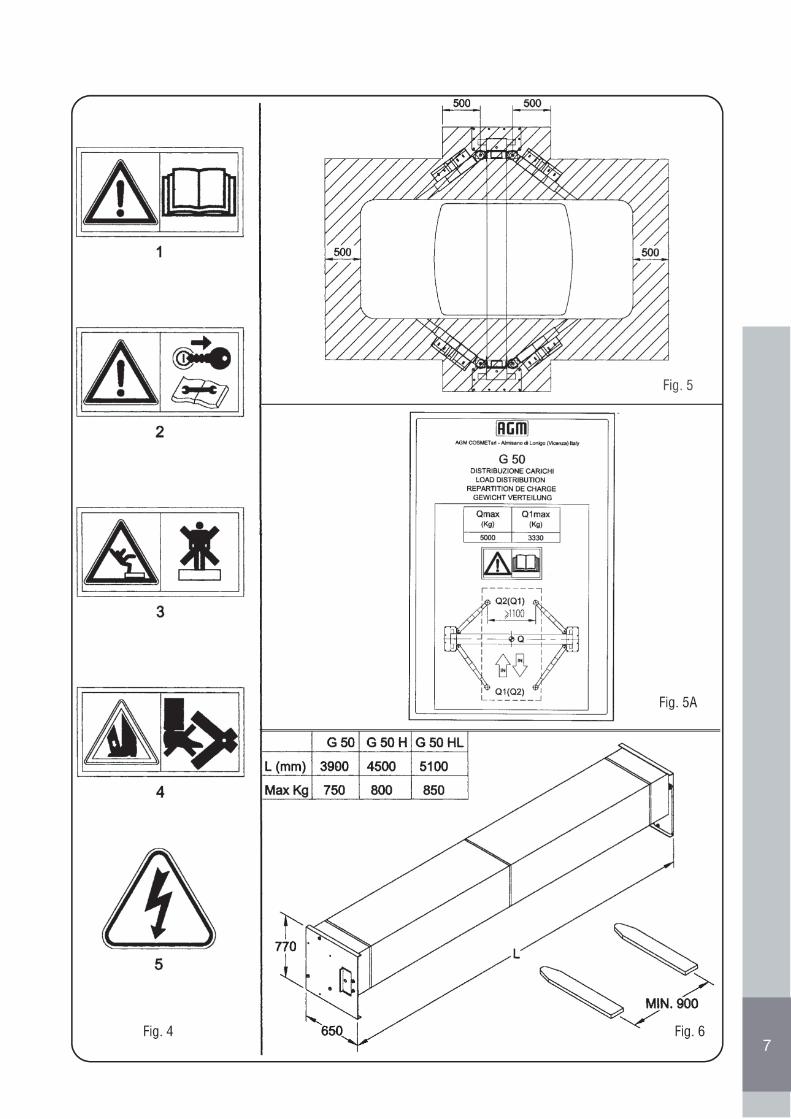
• E’ vietato sovraccaricare il ponte: l’uso del ponte è consentito solo ed esclusivamente per il sollevamento entro la portata indicata nellatabella “DISTRIBUZIONE CARICHI” (Fig. 5), posizionando obbligatoriamente gli automezzi sul ponte in maniera tale da soddisfare contemporaneamente le seguenti condizioni dettate dalla normativa europea EN 1493:1998:
1. Il peso del veicolo da sollevare, rappresentato dalla somma dei 2 carichi Q1 e Q2 (vedere simboli in Fig. 5), non deve superare laportata massima del sollevatore (Qmax); cioè (Q1+Q2) ≤ Qmax
2. il carico Q1 massimo (Q1max) posizionato indifferentemente sulla coppia di bracci corti o lunghi, non deve superare i 3330 Kg comeindicato in Fig. 5, cioè (Q1max ≤ 3330 Kg)
La Ditta AGM Srl declina ogni e/o qualsiasi responsabilità per danni arrecati a persone, animali o cose, dovuti alla mancata osservanza delle istruzioni appena descritte e/o all’ uso improprio del ponte non contemplati nel presente libretto.• E’ obbligatorio installare il sollevatore su un pavimento livellato, liscio ed orizzontale.• E’ obbligatorio installare il sollevatore in prossimità di una presa di corrente e collegare lo stesso tramite una presa elettrica a spina del tipo
conforme alle norme in vigore nel Paese dove viene installato il sollevatore.• E’ obbligatorio Installare il sollevatore in luogo protetto dall’acqua, dal ghiaccio e dal vento.• E’ obbligatorio prima di mettere in funzione il sollevatore, controllare la perfetta integrità di tutte le sicurezze e dei sollevatore stesso.• E’ obbligatorio che l’automezzo da sollevare, sia condotto o manovrato solamente da personale idoneo alla guida come previsto dalle leggi
in vigore nel Paese di utilizzo dei sollevatore.• E’ obbligatorio verificare, prima di mettere in funzione il sollevatore, che all’interno dell’area di pericolo (Fig. 5) o nelle vicinanze, non vi siano
persone estranee o animali.• Si consiglia prima di iniziare il lavoro di familiarizzare con i dispositivi di Comando e le loro funzioni.• Si consiglia prima di iniziare il lavoro di familiarizzare con i dispositivi di comando e le loro funzioni.• Si consiglia di prestare attenzione durante la manovra di salita dei sollevatore, essendo gli automezzi di varie misure, a non schiacciare
l’automezzo contro il soffitto dell’officina.• E’ obbligatorio prima di eseguire la manovra di salita dell’automezzo, effettuare una escursione di 10 cm verso l’atto; verificare quindi la
stabilità dei carico.• Si consiglia prima di eseguire la manovra di discesa dei sollevatore, verificare che sotto ed intorno all’automezzo sollevato non vi siano
oggetti; eventualmente rimuoverli.• E’ obbligatorio prima di lasciare il posto di lavoro, abbassare il ponte e ruotare l’interruttore/Sezionatore D’emergenza (19 Fig. 2) in
pos. OFF.• E’ vietato modificare in qualsiasi modo la centralina idraulica (17 Fig. 3).• E’ obbligatorio che sulla zona sovrastante il sollevatore, non siano presenti apparecchiature connesse alla rete elettrica. In caso di collisione
di tali apparecchiature coi sollevatore o con l’automezzo si potrebbero verificare scariche elettriche pericolose per le persone.• È obbligatorio in caso di pericolo per le persone,per gli animali o cose,ruotare tempestivamente l’interruttore/Sezionatore D’emergenza (19
Fig. 2) sia in pos. OFF.• Si consiglia in caso di contatto della pelle con l’olio dell’impianto idraulico, lavarsi abbondantemente con acqua e sapone.• E’ obbligatorio alzare il sollevatore in modo tale da poter accedere sotto all’automezzo avendo sempre uno spazio sufficiente per camminare
in posizione eretta.• E’ obbligatorio effettuare l’allineamento dei carrelli sempre prima di iniziare ad operare con il sollevatore e, durante l’uso, dopo alcuni cicli
di salita-discesa.• E’ vietato operare con il sollevatore quando, dopo un’operazione di allineamento dei carrelli, i bracci porta carico rimangono disallineati: si
può verificare la caduta del veicolo.• E’ obbligatorio in caso di malfunzionamento del sollevatore interrompere le operazioni ed interpellare sempre il costruttore o l’officina daesso
autorizzata.• E’ vietato operare con il sollevatore quando durante l’uso si notano anomalie o malfunzionamenti.
Per la pulizia del sollevatore usare solamente un panno morbido. Nei punti in cui sono presenti macchie di olio o grasso è possibile inumidire leggermente il panno con alcool per sgrassare la superficie. Non usare altri solventi perché potrebbero rovinare sia le parti plastiche che verniciate.
• E’ obbligatorio controllare periodicamente l’integrità dei dispositivi di protezione e della struttura.• E’ obbligatorio verificare periodicamente il serraggio e la tenuta delle viti, dei dadi e dei raccordi.• E’ obbligatorio controllare periodicamente che gli organi mobili di sollevamento (rulli, perni etc.) siano in buono stato e ben lubrificati.• Si consiglia di rispettare la conformità degli oli consigliati.• E’ obbligatorio che le parti di ricambio corrispondano alle esigenze definite dal Costruttore. Usare solo ricambi originali.• E’ obbligatorio che le operazioni di spostamento e sollevamento dei sollevatore o delle sue singole parti siano effettuate con modalità, funi,
corde, catene e accessori di sollevamento, idonei e conformi alle norme in vigore nel Paese dove avvengono le suddette operazioni.• E’ obbligatorio che l’installazione sia eseguita in modo che il sollevatore o l’automezzo da sollevare non possano schiacciare, agganciare
o sfregare altri oggetti, in particolare gli impianti elettrici, dell’acqua e dei gas.• E’ vietato rimuovere o manomettere i dispositivi di sicurezza.• E’ obbligatorio che l’installazione e la manutenzione dei sollevatore siano effettuate solamente da personale qualificato e seguendo le
indicazioni riportate in questo manuale.• E’ obbligatorio staccare l’alimentazione elettrica ogni qualvolta si debba intervenire per’ riparazioni o manutenzioni.• E’ obbligatorio eseguire scrupolosamente la manutenzione come indicato in questo manuale; far sostituire agli addetti, le parti danneggiate
o usurate.• E’ vietato eseguire saldature, tagli o fori sulle parti dei sollevatore.• E’ obbligatorio effettuare interventi e regolazioni sull’attrezzatura sempre con l’alimentazione elettrica staccata.• E’ obbligatorio pulire quando sono sporche e sostituire immediatamente quando staccate o danneggiate le etichette con le istruzioni appli-
cate sul sollevatore che forniscono i necessari consigli in forma essenziale per evitare gli infortuni.• Si consiglia di asportate completamente le macchie d’olio sul pavimento non appena individuate perché possono essere molto pericolose.
3.0 MOVIMENTAZIONE E INSTALLAZIONE
3.1 TRASPORTO E SCARICO
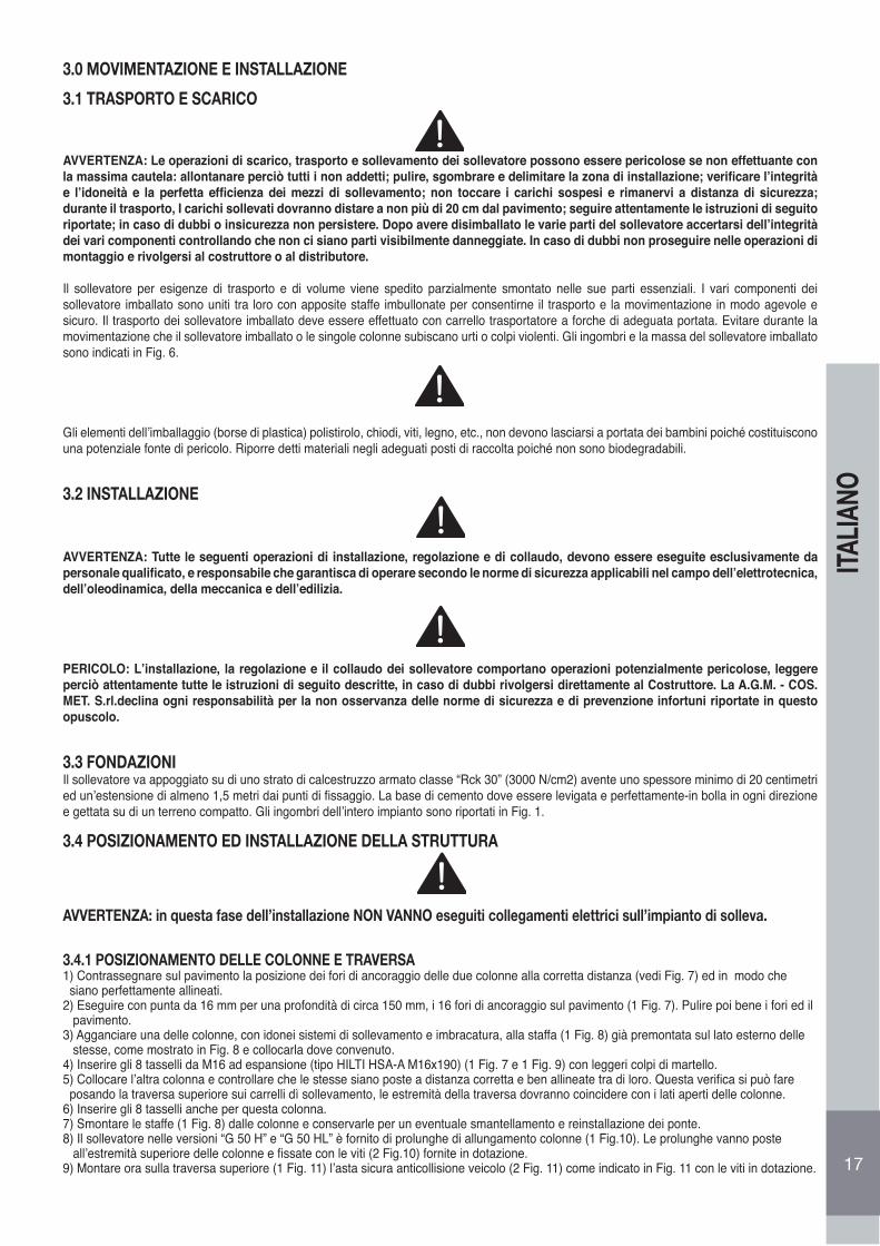
AVVERTENZA: Le operazioni di scarico, trasporto e sollevamento dei sollevatore possono essere pericolose se non effettuante con la massima cautela: allontanare perciò tutti i non addetti; pulire, sgombrare e delimitare la zona di installazione; verificare l’integrità e l’idoneità e la perfetta efficienza dei mezzi di sollevamento; non toccare i carichi sospesi e rimanervi a distanza di sicurezza; durante il trasporto, I carichi sollevati dovranno distare a non più di 20 cm dal pavimento; seguire attentamente le istruzioni di seguito riportate; in caso di dubbi o insicurezza non persistere. Dopo avere disimballato le varie parti del sollevatore accertarsi dell’integrità dei vari componenti controllando che non ci siano parti visibilmente danneggiate. In caso di dubbi non proseguire nelle operazioni di montaggio e rivolgersi al costruttore o al distributore.
Il sollevatore per esigenze di trasporto e di volume viene spedito parzialmente smontato nelle sue parti essenziali. I vari componenti dei sollevatore imballato sono uniti tra loro con apposite staffe imbullonate per consentirne il trasporto e la movimentazione in modo agevole e sicuro. Il trasporto dei sollevatore imballato deve essere effettuato con carrello trasportatore a forche di adeguata portata. Evitare durante la movimentazione che il sollevatore imballato o le singole colonne subiscano urti o colpi violenti. Gli ingombri e la massa del sollevatore imballato sono indicati in Fig. 6.
Gli elementi dell’imballaggio (borse di plastica) polistirolo, chiodi, viti, legno, etc., non devono lasciarsi a portata dei bambini poiché costituiscono una potenziale fonte di pericolo. Riporre detti materiali negli adeguati posti di raccolta poiché non sono biodegradabili.
3.2 INSTALLAZIONE
AVVERTENZA: Tutte le seguenti operazioni di installazione, regolazione e di collaudo, devono essere eseguite esclusivamente da personale qualificato, e responsabile che garantisca di operare secondo le norme di sicurezza applicabili nel campo dell’elettrotecnica, dell’oleodinamica, della meccanica e dell’edilizia.
PERICOLO: L’installazione, la regolazione e il collaudo dei sollevatore comportano operazioni potenzialmente pericolose, leggere perciò attentamente tutte le istruzioni di seguito descritte, in caso di dubbi rivolgersi direttamente al Costruttore. La A.G.M. - COS.MET. S.rl.declina ogni responsabilità per la non osservanza delle norme di sicurezza e di prevenzione infortuni riportate in questo opuscolo.
3.3 FONDAZIONIIl sollevatore va appoggiato su di uno strato di calcestruzzo armato classe “Rck 30” (3000 N/cm2) avente uno spessore minimo di 20 centimetri ed un’estensione di almeno 1,5 metri dai punti di fissaggio. La base di cemento dove essere levigata e perfettamente-in bolla in ogni direzione e gettata su di un terreno compatto. Gli ingombri dell’intero impianto sono riportati in Fig. 1.
3.4 POSIZIONAMENTO ED INSTALLAZIONE DELLA STRUTTURA
AVVERTENZA: in questa fase dell’installazione NON VANNO eseguiti collegamenti elettrici sull’impianto di solleva.
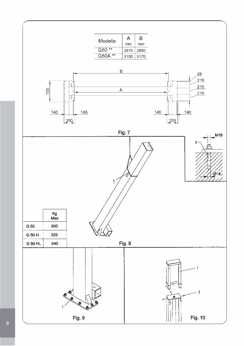
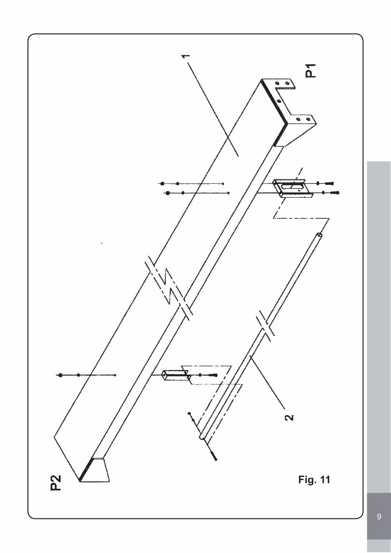
3.4.1 POSIZIONAMENTO DELLE COLONNE E TRAVERSA1) Contrassegnare sul pavimento la posizione dei fori di ancoraggio delle due colonne alla corretta distanza (vedi Fig. 7) ed in modo che siano perfettamente allineati.2) Eseguire con punta da 16 mm per una profondità di circa 150 mm, i 16 fori di ancoraggio sul pavimento (1 Fig. 7). Pulire poi bene i fori ed il pavimento.3) Agganciare una delle colonne, con idonei sistemi di sollevamento e imbracatura, alla staffa (1 Fig. 8) già premontata sul lato esterno delle stesse, come mostrato in Fig. 8 e collocarla dove convenuto.4) Inserire gli 8 tasselli da M16 ad espansione (tipo HILTI HSA-A M16x190) (1 Fig. 7 e 1 Fig. 9) con leggeri colpi di martello.5) Collocare l’altra colonna e controllare che le stesse siano poste a distanza corretta e ben allineate tra di loro. Questa verifica si può fare posando la traversa superiore sui carrelli dì sollevamento, le estremità della traversa dovranno coincidere con i lati aperti delle colonne.6) Inserire gli 8 tasselli anche per questa colonna.7) Smontare le staffe (1 Fig. 8) dalle colonne e conservarle per un eventuale smantellamento e reinstallazione dei ponte.8) Il sollevatore nelle versioni “G 50 H” e “G 50 HL” è fornito di prolunghe di allungamento colonne (1 Fig.10). Le prolunghe vanno poste all’estremità superiore delle colonne e fissate con le viti (2 Fig.10) fornite in dotazione.9) Montare ora sulla traversa superiore (1 Fig. 11) l’asta sicura anticollisione veicolo (2 Fig. 11) come indicato in Fig. 11 con le viti in dotazione. 17
ITAL
IANO
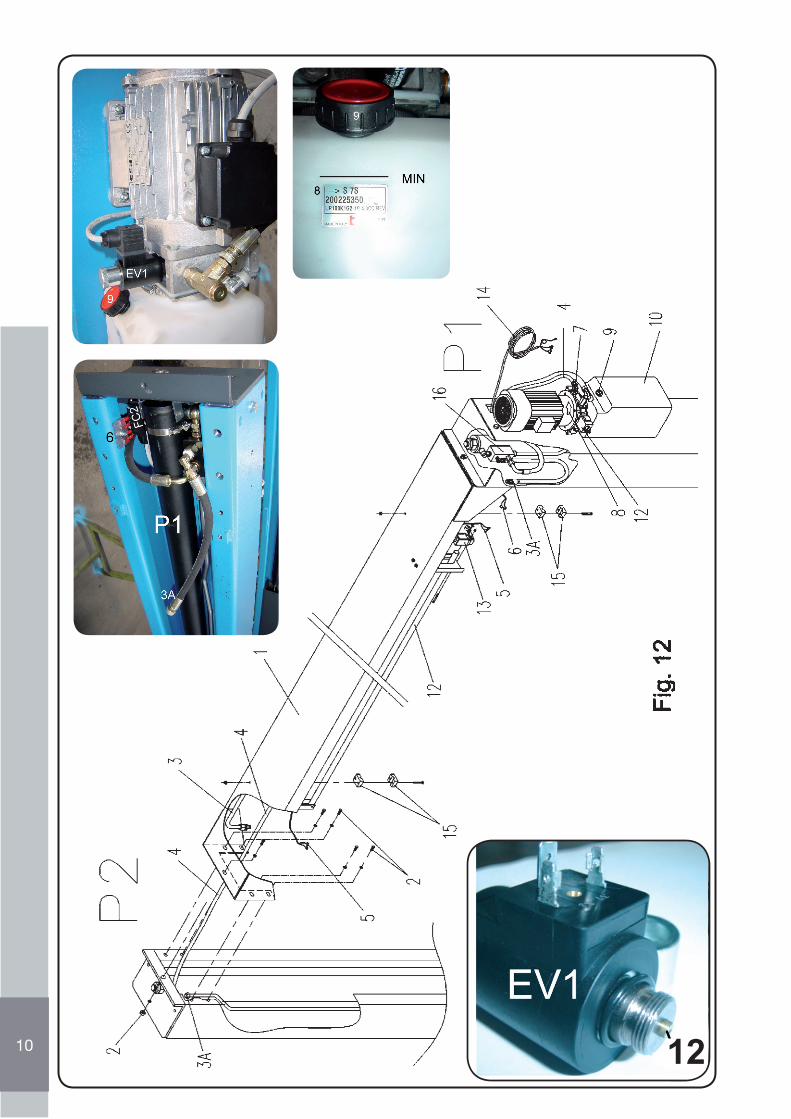
10) Sollevare, con idonei sistemi di sollevamento e imbracatura, la traversa di collegamento (1 Fig. 12), posizionarla tra le due estremità superiori delle colonne e fissarla ad esse con le viti in dotazione (2 Fig. 12).11) Montare il finecorsa di sicurezza anticollisione veicolo (10 Fig. 12), con le viti in dotazione, alla staffa della traversa come indicato in Fig. 12 ed in modo che il tubo di sicurezza (11 Fig. 12), si trovi sotto alla leva dei finecorsa. Se il tubo di sicurezza viene spinto verso l’alto deve far intervenire il finecorsa (Fig. 12).12) Serrare i bulloni dei tasselli (1 Fig. 7 e 1 Fig. 9 ) con coppia di serraggio pari a 100 Nm. Se i tasselli girano a vuoto, vanno sostituiti con tipo maggiorato.
3.4.2 COLLEGAMENTI OLEODINAMICI
CAUTELA. In questa fase dell’installazione NON VANNO eseguiti collegamenti elettrici sull’impianto di sollevamento.
CAUTELA. E’ molto Importante seguire correttamente le indicazioni riguardanti i collegamenti dell’impianto oleodinamico
AVVERTENZA: Prima di effettuare le prossime operazioni leggere le indicazioni riportate nel capitolo 4.0 riguardanti le funzioni delquadro comando e acquisire la giusta dimestichezza eseguendo le varie operazioni a sollevatore scarico.
18
ITAL
IANO
• Collegare il tubo in ferro trasversale (3 Fig. 12), che si trova all’interno della traversa di collegamento (1 Fig. 12), ai rispettivi raccordi l’interno delle due colonne (3A Fig. 12), Nelle versioni “G 50 H” e ”G 50 HL” con prolunghe di allungamento colonne vengono dati in dotazione i due spezzoni di tubo con i rispettivi raccordi per collegare i tubi della colonna con quelli della traversa.
• Estrarre dalla colonna P2 il tubo di scarico in gomma (4 Fig. 12), portarlo fino alla centralina idraulica e connetterlo ad essa collegandolo al relativo raccordo (7 Fig. 12).
• Controllare infine che tutti i raccordi siano ben serrati.• Fissare il tubo trasversale (3 Fig. 12), al centro traversa con i morsetti in dotazione (15 Fig. 12).
3.4.3 COLLEGAMENTI ELETTRICI
• La tensione elettrica di allacciamento al quadro del sollevatore, deve corrispondere alla tensione indicata sul quadro elettrico.• Il quadro elettrico deve essere allacciato ad un interrutore generale costruito ed installato secondo le normative in vigore nel Paese
di utilizzo.• L’impianto che eroga l’energia elettrica al quadro elettrico del sollevatore, deve essere eseguito secondo le normative del Paese di
utilizzo.• La potenza minima necessaria é di 3kW.• La sezione minima dei fili elettrici del circuito di potenza deve essere di 4 mm2• In Questa fase, il motore elettrico può essere azionato solo per alcuni istanti, onde evitare danneggiamenti alla pompa idraulica.
PROCEDURA:• Collegare il cavo dei microinterruttore montato nella traversa di collegamento (5 Fig. 12) alla connessione numerata (6 Fig. 12) nella co-
lonna P1.• Collegare il cavo dell’elettromagnete della colonna P2 alla sua connessione numerata nella colonna P1.• Collegare il cavo di alimentazione elettrica (14 Fig. 12) che fuoriesce dalla colonna P1 alla rete di alimentazione. Il collegamento deve
essere eseguito rispettando le normative dei Paese di utilizzo.
• Mettere in tensione la linea e controllare che l’interruttore/Sezionatore D’emergenza (19 Fig. 2) sia in posizione ON (eventualmente ruotarlo).
• Premere e rilasciare il pulsante “SALITA’(22 Fig. 2) e controllare che il senso di rotazione dei motore sia lo stesso della freccia (8 Fig. 12)stampata sulla campana di raccordo della base dei motore (in senso orario guardando dal carter superiore dei motore). In caso contrario,togliere la tensione dalla rete e invertire due fasi sulla morsettiera della scatola di derivazione.
L’operazione di allineamento dei carrelli deve sempre essere effettuata scrupolosamente da personale qualificato e responsabile perchèè di fondamentale importanza per il buon funzionamento del sollevatore e per la sicurezza dell’operatore.
PERICOLO: E’ vietato operare con il sollevatore quando, dopo un’operazione di allineamento dei carrelli, i bracci porta carico sidiseallineano rapidamente.
19
ITAL
IANO
3.4.4 RIEMPIMENTO IMPIANTO OLEODINAMICO
AVVERTENZA:Controllare costantemente che non vi siano perdite d’olio, eventualmente togliere la tensione elettrica e serrare i raccordi allentati.
Procedere al sollevamento dei carrelli, nel seguente modo:• Svitare il tappo di introduzione olio (9 Fig. 12) e introdurre nel serbatoio (10 Fig. 12) it 7 di olio idraulico ESSO NUTO H32 o equivalente
(viscosità ISO VG 32).• Premere il pulsante “SALITA (22 Fig. 2) e mantenerlo premuto fino a portare il carrello P1 ad un’altezza di 50 cm. circa.• Posizionare i bracci (6 Fig. 2) in prossimità dei carrelli (4 Fig. 2) in modo che i bracci (6 Fig. 2) vengano montati con le protezioni salvapiedi
(14 Fig. 2) rivolte verso l’esterno dei sollevatore.• Montare i due rispettivi bracci al carrello sollevato tramite la spina (2 Fig. 14) bloccandola con i due anelli elastici (3 Fig. 14) alle estremità,
facendo attenzione durante il montaggio di posizionarli correttamente con le sicurezze antirotazione bracci (5 Fig. 14): queste devono avere il settore dentato rivolto verso la cremagliera (4 Fig. 14) di ciascun braccio. Tirando verso l’alto il pomello (5 Fig. 14), si possono escludere temporaneamente le sicurezze antirotazione bracci.
• Premere il pulsante “SALITA” (22 Fig. 2) e mantenerlo premuto fino a quando il carrello Pl arriva alla massima altezza. A questo punto versare nel serbatoio altri 3 litri di olio.
• Premere nuovamente il pulsante “SALITA” (22 Fig. 2) fino a che il carrello P2 raggiunge un’altezza di 50 cm. circa.• Montare i bracci al carrello della colonna P2, ripetendo le operazioni riportate al punto 4.• Premere ancora il pulsante “SALITA” (22 Fig. 2) fino a che il carrello P2 raggiunge la massima altezza. Dopo il raggiungimento della mas-
sima altezza, tenere ancora premuti i pulsanti per 10 ÷ 15 secondi per permettere lo spurgo dell’aria.
3.4.5. ALLINEAMENTO CARRELLI3.4.5.1 ALLINEAMENTO CARRELLI ALLA MESSA IN SERVIZIO
1. Premere il pulsante DISCESA (23 Fig. 2) portando i carrelli alla minima altezza.2. Premere il pulsante “SALITA” (22 Fig. 2) fino a che i due carrelli raggiungono la massima altezza.3. Dopo 5 ÷ 10 minuti di sosta, per permettere la separazione dell’eventuale aria presente nell’olio, eseguire ancora un ciclo di SALITA- DISCESA come indicato al punto 1) e 2), verificando il funzionamento dei dispositivi di sicurezza come descritto in questo opuscolo.4. A carrelli completamente abbassati, controllare ed eventualmente ripristinare il livello dell’olio fino a raggiungere il giusto livello, 2 ÷ 3 cm. sotto il foro di immissione olio.
3.4.5.2 ALLINEAMENTO IN ESERCIZIO
Durante l’uso l’allineamento dei carrelli viene mantenuto automaticamente dal sistema oleodinamico dei martinetti posti in serie con circuito a travaso. Non di meno è obbligatorio effettuare sempre l’allineamento ogni qualvolta si nota una leggera differenza di altezza fra i due carrelli. In tal caso premere il pulsante “SALITA” (22 fig. 2) fino a che entrambi i carrelli raggiungono la massima altezza. Tenere premuto per alcuni secondi. (Questa manovra, è possibile attuarla anche durante il normale utilizzo con il veicolo caricato sul sollevatore, purchè il disallineamento tra i carrelli sia massimo 3÷4 cm.) Procedere poi con la manovra di discesa.
AVVERTENZA Durante questa manovra controllare che il disallineamento dei carrelli rimanga costante
20
ITAL
IANO
3.4.6 APPLICAZIONE TARGHETTE ADESIVE E PITTOGRAMMI
Applicare al sollevatore le targhette adesive allegate al presente libretto, seguendo la disposizione dello schema a Fig. 3.
AVVERTENZA: la mancata applicazione delle targhette causa la decadenza delle condizioni di garanzia e la decadenza delle responsabilità dei costruttore da ogni danno derivante dall’uso dei sollevatore.
In caso di danneggiamento, deterioramento con conseguente illeggibilità o smarrimento di una o più targhette dei sollevatore, fame richiesta al venditore precisando il numero di posizione indicato in Fig. 3. Applicare quindi appena possibile le nuove etichette in posizione corretta sul sollevatore.
4.0 ISTRUZIONI PER L’USO
AVVERTENZA. Leggere le indicazioni riportate nel capitolo “Norme di sicurezza e di prevenzione infortuni”.
AVVERTENZA. Prima di effettuare qualsiasi operazione sulla chiave di comando assicurarsi che nessuna persona alla nelle vicinan-ze dei sollevatore.
4.1 PULSANTIERASono di seguito riportate le operazioni eseguibili dalla pulsantiera:
4.1.1 SALITA SOLLEVATORE
• Controllare che l’interruttore/Sezionatore D’emergenza (19 Fig. 2) sia in posizione sollevata (eventualmente ruotarlo).• Premere il pulsante SALITA 21 (Fig. 3) fino al raggiungimento dell’altezza voluta.
Al rilascio del pulsante di salita, il sollevatore effettua la fase di STAZIONAMENTO AUTOMATICO dei carrelli, permettendo così agli stessi di scendere e alle sicure meccaniche di inserirsi.
IMPORTANTE: La funzione di STAZIONAMENTO IN AUTOMATICO, rilasciando il pulsante di SALITA (22 Fig. 2), è predispostaad non entrare in funzione e ad autoescludersi, fintantoché il profilo inferiore del carrello (Fig. 14), non supera la quota di circa20 cm da terra, garantendo quindi l’arresto istantaneo durante la delicata fase iniziale di salita.
AVVERTENZA Prima di iniziare con la manovra di salita, leggere attentamente ed assimilare quanto indicato nel §4.2PROCEDURA DI SOLLEVAMENTO.
4.1.2 DISCESA SOLLEVATORE
Premere il pulsante DISCESA (23 Fig. 2) fino al raggiungimento dell’altezza voluta.
Nel premere il pulsante di DISCESA (22Fig. 3), i carrelli si sollevano per un breve tratto, permettendo così alle sicure meccani-che di sganciarsi, per poi scendere fintanto si tiene premuto il pulsante. Al rilascio del pulsante di DISCESA (22Fig. 3), il sol-levatore effettua la fase di STAZIONAMENTO AUTOMATICO dei carrelli, permettendo così agli stessi di scendere e alle sicure meccaniche di inserirsi.
IMPORTANTE: La funzione di STAZIONAMENTO IN AUTOMATICO, rilasciando il pulsante di DISCESA (23 Fig. 2), è predisposta ad non entrare in funzione e ad autoescludersi, quando il carrello (Fig. 14), scendendo dall’alto al basso raggiunge la quota di circa 20 cm da terra.
4.1.3 INTERRUTTORE /SEZIONATORE DI EMERGENZA/OFF• Ruotando l’interruttore /Sezionatore D’emergenza (18 Fig. 2) in pos.0 (OFF), il sollevatore smette completamente di funzionare.• Questa operazione va fatta sempre prima di accedere alla zona di lavoro sotto il sollevatore.• Riportando l’interruttore /Sezionatore D’emergenza in posizione I (ON), si autorizzano le funzioni del ponte.
In caso di difetto o di guasto di uno o più componenti od in caso di anomalia o avaria del circuito di alimentazione non sussistono situazionidi rischio perché il SOLLEVATORE è dotato di dispositivo di sezionamento della linea elettrica che permette di isolare la macchina. I comandi di salita e discesa, inoltre, sono del tipo “a uomo presente” (ad azione mantenuta) per cui, in caso di avaria del circuito di alimentazione non sono possibili né l’avviamento intempestivo, né l’impedimento dell’arresto se è già stato dato il comando tramite il sezionatore, né la caduta del carico o l’inefficienza dei dispositivi di protezione.
Le parti mobili durante il movimento di salita o discesa, vengono quindi sempre arrestate in caso di avaria del circuito di alimentazione. Al ripristino del circuito di alimentazione di energia non sussistono situazioni di rischio perché ogni movimento del Sollevatore deve essere attivato manualmente dall’operatore agendo sul selettore di comando ad azione mantenuta.
AVVERTENZA: Prima di lasciare incustodito il sollevatore, l’operatore DEVE oltre a posizionare l’interruttore/Sezionatore d’emergenza (18 Fig. 2) in posizione 0 (OFF) anche bloccarne meccanicamente il movimento rotatorio mediante l’inserimento nell’apposito foro di un lucchetto (NON fornito in dotazione col sollevatore)
4.1.5 SPIA PRESENZA TENSIONE• La spia presenza tensione (21 Fig. 2) sì illumina quando il pulsante di ripristino/ON autorizza tutte le funzioni dei comandi e quindi dei ponte.
AVVERTENZA: Quando la spia presenza tensione è accesa non si deve accedere alla zona in prossimità dei ponte.
4.1.6 ESCLUSIONE STAZIONAMENTO AUTOMATICOPremendo contemporaneamente il pulsante ESCLUSIONE STAZIONAMENTO AUTOMATICO (24 Fig. 2) e i pulsanti SALITA 22 Fig. 2 o DISCESA (23 Fig. 2), si evita l’operazione di stazionamento automatico.
Questa funzione resta attiva per circa 7 secondi, dopodiché, ritorna abilitata la funzione dello stazionamento automatico
AVVERTENZA: Quando la spia presenza tensione è accesa non si deve accedere in prossimità del ponte.
4.2 PROCEDURA DI SOLLEVAMENTO Per procedere al sollevamento dell’automezzo operare nel seguente modo:
• E’ obbligatorio posizionare gli automezzi sul sollevatore in modo che il peso sia ben ripartito e centrato; le portiere devono rimanere chiuse; non devono sporgere oggetti al di fuori della sagoma dell’automezzo; il baricentro dell’automezzo deve ricadere all’interno dei 4 appoggi; montando alcune parti dell’automezzo, il baricentro può spostarsi. • E’ vietato sovraccaricare il ponte: l’uso del ponte è consentito solo ed esclusivamente per il sollevamento entro la portata indicata nella tabella “DISTRIBUZIONE CARICHI” (Fig. 5), posizionando obbligatoriamente gli automezzi sul ponte in maniera tale da soddisfare contemporaneamente le seguenti condizioni dettate dalla normativa europea EN 1493:1998: 1. Il peso del veicolo da sollevare, rappresentato dalla somma dei 2 carichi Q1 e Q2 (vedere simboli in Fig. 5), non deve superare la portata massima del sollevatore (Qmax); cioè (Q1+Q2) ≤ Qmax 2. il carico Q1 massimo (Q1max) posizionato indifferentemente sulla coppia di bracci corti o lunghi, non deve superare i 3330 Kg come indicato in Fig. 5, cioè (Q1max ≤ 3330 Kg)
La Ditta AGM Srl declina ogni e/o qualsiasi responsabilità per danni arrecati a persone, animali o cose, dovuti alla mancataosservanza delle istruzioni appena descritte e/o all’ uso improprio del ponte non contemplati nel presente libretto.
• Premere l’interruttore/Sezionatore D’emergenza (19 Fig. 2).• Controllare che i bracci siano ruotati in modo da non intralciare l’entrata dell’automezzo tra le colonne del sollevatore.• Situare l’automezzo in maniera che risulti posizionato e centrato rispetto alle colonne dei sollevatore.• Ruotare i bracci e sfilare le prolunghe in modo che i tamponi siano posizionati in corrispondenza dei punti previsti per il sollevamento come indicato dal costruttore dell’automezzo. AVVERTENZA: Prima di procedere al sollevamento dell’automezzo si deve sempre effettuare il controllo della distribuzione deicarichi in rapporto alla massa del veicolo rispettando la tabella DISTRIBUZIONE CARICHI (FIG. 5). Se i valori riscontrati non rientranonei limiti della tabella DISTRIBUZIONE CARICHI non si deve assolutamente procedere al sollevamento del veicolo• Ruotare l’interruttore/Sezionatore D’emergenza (19 Fig. 2) nel senso della freccia, riportandolo in posizione sollevata.• Premere il pulsante di ripristino/ON (20 Fig. 2).• Sollevare l’automezzo per 10 centimetri.
21
ITAL
IANO
22
ITAL
IANO
• Verificare il corretto inserimento dei tamponi in gomma.• Verificare la stabilità dell’automezzo.• Procedere con il sollevamento dell’automezzo.• Premere il pulsante di SALITA (22 Fig. 2 - vedere 4.1.1 -).• Premere a fondo il l’interruttore/Sezionatore D’emergenza (19 Fig. 2) prima di accedere sotto al ponte.
4.3 PROCEDURA PER LA DISCESA
Per procedere alla discesa, operare nel seguente modo:
• Ruotare l’interruttore/Sezionatore D’emergenza (19 Fig. 2 ) nel senso della freccia, portandolo in posizione sollevata.• Premere il pulsante di ripristino/ON (20 Fig. 2).• Premere il pulsante di discesa (23 Fig. 2) portando i carrelli alla minima altezza.• Premere a fondo l’interruttore/Sezionatore D’emergenza (19 Fig. 2)• Ruotare i bracci in modo da non intralciare l’uscita dell’automezzo e chiudere le prolunghe.• Portare l’automezzo al di fuori dell’area di sollevamento.
4.4 DISPOSITIVI Di SICUREZZA
AVVERTENZA: I seguenti dispositivi di sicurezza non devono assolutamente essere manomessi o esclusi, vanno inoltre tenuti sem-pre in ottimo stato di efficienza:• Sicurezze salvapiedi applicate ai bracci (14 Fig. 2) impediscono l’eventuale schiacciamento dei piede della persona durante la fase finale
di discesa dei bracci.• Spia presenza tensione (21 Fig. 2): quando è illuminata significa che non si può accedere al ponte.• Sicurezze meccaniche antirotazione dei bracci ad inserimento automatico (15 Fig. 2 e 1 Fig. 14): impediscono, a carrello sollevato, la
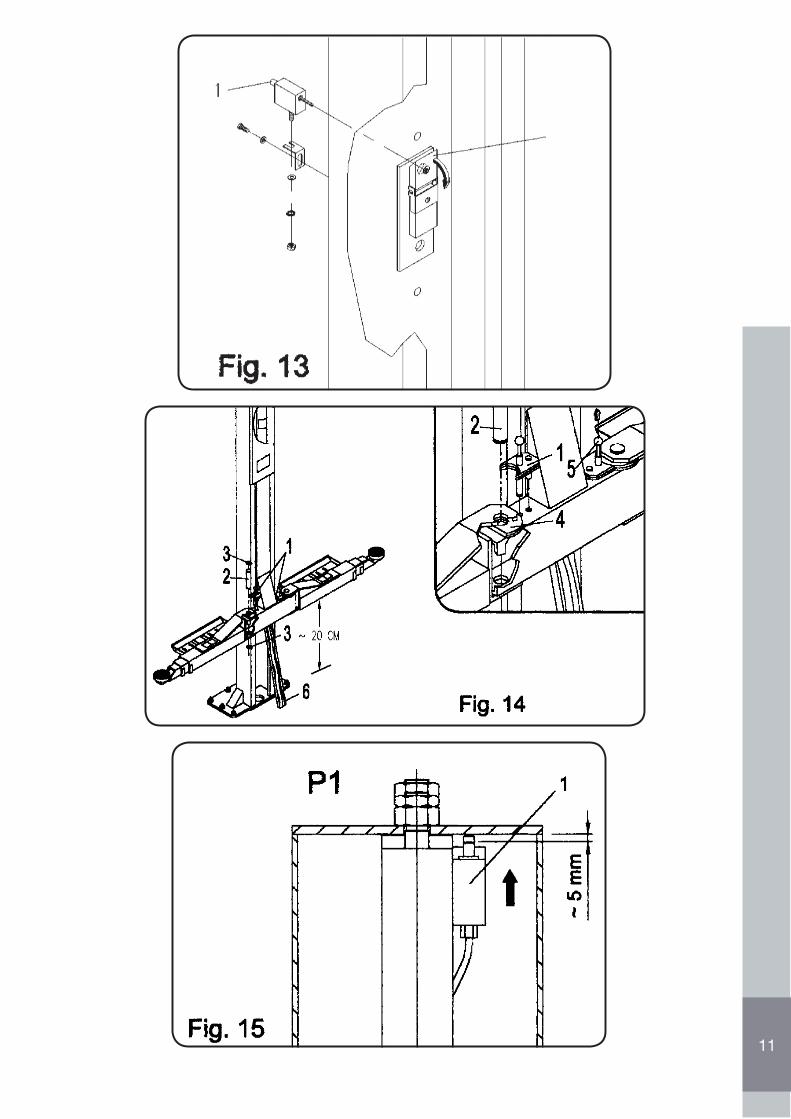
rotazione dei bracci di sollevamento.• Sicurezze meccaniche anticaduta carrelli (1 Fig. 13): impediscono la discesa dei carrelli a causa di trafilamenti dei circuito idraulico o di
rottura degli organi meccanici di sollevamento.• Valvole di sicurezza (schema idraulico): impediscono la discesa dei carrelli in caso di improvviso calo di pressione al circuito idraulico o la
discesa di un solo carrello se uno di questi non scende perché bloccato meccanicamente• L’interruttore/Sezionatore D’emergenza (19 Fig. 2): se premuto si blocca il funzionamento dei ponte.• Circuito elettrico ausiliario a bassa tensione: questo circuito non provoca la “scossa elettrica”.• Sicurezza anticollisione veicolo (16 Fig. 2 e 2 Fig. 11): blocca la salita dei ponte se il veicolo sollevato sta per urtare la traversa superiore.• Quadro comando “a uomo presente”: tutte le funzioni necessitano della presenza dell’operatore per gestire il funzionamento del solleva-
tore.
4.5 DISCESA Di EMERGENZA
AVVERTENZA: Eseguendo la “discesa di emergenza” dei carrelli , si escludono le sicurezze meccaniche anticaduta carrelli.
Le seguenti operazioni devono perciò essere eseguito solamente:• Quando il sollevatore non scendo a causa^di guasto elettrico o per mancanza di energia elettrica;• In caso di assoluta necessità;• Da un solo addetto qualificato;• Delimitando prima l’area dell’impianto di sollevamento e rendendola accessibile al solo addetto.
Procedura discesa di emergenza carrelli:• Ruotare l’interruttore/Sezionatore D’emergenza (23 Fig. 2) in posizione OFF.• Se il ponte è in posizione di stazionamento, le sicurezze non si apriranno. Le successive operazioni saranno quindi possibili solo se il ponte è dotato di pompa manuale di emergenza, fornita a richiesta con relative istruzioni per l’uso, azionando la quale è possibile sollevare il ponteper liberare le sicurezze meccaniche.• Aprire i carter, azionare manualmente gli elettromagneti (1 Fig. 13) per aprire le sicure (2 Fig. 13).• Procedere con la discesa manuale eseguendo le seguenti operazioni:1) Procedere con la discesa manuale togliendo completamente il coperchio della elettrovalvola EV1 (17 Fig. 12), e poi molto lentamente premere lo spillo (12 Fig.12) per far scendere il ponte.2) Terminata l’operazione di discesa riavvitare a fondo il coperchio (17 Fig. 14) e riportare in posizione originale i cunei delle sicure meccaniche
PERICOLO: Eseguire accuratamente l’operazione al punto 2.
CAUTELA: Dopo aver ripristinato la normale funzione dei ponte, fare 2 ÷ 3 cicli di SALITA-DISCESA a ponte scarico e controllare il normale funzionamento dei dispositivi di sicurezza come di seguito descritto al punto 5.1.2.
23
ITAL
IANO
5.0 MANUTENZIONE
Vengono di seguito elencate le varie operazioni di manutenzione. Il minor costo di esercizio ed una lunga durata della macchina dipendono, tra l’altro, dalla costante osservanza di tali operazioni.:
CAUTELA: I tempi di intervento elencati, sono forniti a titolo informativo e sono relativi a condizioni normali di impiego, possono infatti subire variazioni in relazione al genere di servizio, ambiente più o meno polveroso, frequenza di utilizzo, ecc.Nel caso di condizioni più gravose, gli interventi di manutenzione vanno incrementati.Nell’eseguire il ripristino o il cambio olio, usare lo stesso tipo di olio usato in precedenza.
5.1.1 SPIA PRESENZA TENSIONE1) Ruotare l’interruttore/Sezionatore D’emergenza (19 Fig. 2) nel senso della freccia, portandolo in posizione sollevata.2) Premere il pulsante di ripristino/ON (20 Fig. 2).3) Verificare che la spia presenza tensione (21 Fig. 2) sia accesa.
AVVERTENZA. Le operazioni di seguito descritte devono essere eseguite a sollevatore scarico.
5.1.2 SICUREZZE MECCANICHE DI STAZIONAMENTO CARRELLI1) Far salire totalmente i carrelli premendo il pulsante di SALITA (22 Fig. 2).2) Rilasciato il pulsante di SALITA (22 Fig. 2) e dopo essersi conclusa la fase di STAZIONAMENTO AUTOMATICO carrelli, controllare dopo aver asportato i carters centrali, posti sulle fiancate esterne di ogni colonna, tirando verso l’esterno le due staffe di comando cunei (1 Fig. 23) collegate all’elettromagnete l’inserimento delle sicure. Se le staffe risultano bloccate significache le sicure (2 Fig. 23) sono inserite.
5.1.3 SICUREZZE CONTRO IL DISALLINEAMENTO DEI CARRELLIFar salire i carrelli a 1 metro circa di altezza da terra e procedere come segue:
Controllo carrello P1:1) Inserire sotto al carrello Pl un travetto in legno (6 Fig. 14) in modo che blocchi la discesa dei carrello.2) Premere il pulsante “DISCESA” (23 Fig. 2). Quando il carrello P1 si blocca sul travetto, subito dopo si deve bloccare anche il carrello P2.
PERICOLO: Se il carrello P2 non si ferma controllare il finecorsa di sicurezza FC2 (1 Fig.15), fissato all’estremità dei cilindro della colonna Pl. L’intervento dei finecorsa FC2 è essenziale ai fini della sicurezza dei sollevatore. Controllare quindi la sua corretta posi-zione e funzionamento (1 Fig.15) prima di rimettere in funzione il sollevatore.
Controllo carrello P2:
1) Inserire sotto al carrello P2 un travetto in legno (6 Fig. 14) in modo che blocchi la discesa del carrello.2) Premere il pulsante “DISCESA” (23 Fig. 2). Quando il carrello P2 si blocca sul travetto, subito dopo si deve bloccare anche il carrello P1.
Se il carrello P1 non si ferma, controllare la valvola di blocco (7 Schema Idraulico), 2 Fig. 15. Eventualmente pulirla con aria com-pressa in caso non funzioni, sostituirla.
5.1.4 TAMPONI CON RIPORTO IN GOMMA
Verificare il loro stato di conservazione, se usurati o rotti, sostituirli.
5.1.5 PULSANTE DI EMERGENZA/OFF
1) Ruotare il pulsante dì emergenza/OFF (19 Fig. 2) nel senso della freccia, portandolo in posizione sollevata.2) Eseguire le operazioni per la DISCESA o SALITA.3) Premere contemporaneamente il pulsante di emergenza/OFF (19 Fig. 2); i carrelli si devono arrestare.
24
ITAL
IANO
5.2 MANUTENZIONE PERIODICA
5.2.1 OGNI SETTIMANA
• Ogni settimana verificare i dispositivi di sicurezza come indicato in questo opuscolo.• Controllare il livello dell’olio idraulico nel seguente modo:• Far scendere totalmente i carrelli e controllare che il livello sia in corrispondenza dell’indicatore, 2 ÷ 3 cm sotto il foro (10 Fig. 12).• Eventualmente rabboccare, attraverso il tappo (9 Fig. 12), con olio idraulico “ESSO NUTO H32” o equivalente.
5.2.2 OGNI MESE
• Verificare il serraggio della viteria dei ponte;• Controllare la tenuta dell’impianto idraulico, eventualmente serrare i raccordi allentati;• Controllare lo stato di conservazione dei tubi oleodinamici; in caso di usura, sostituirli con nuovi e di pari tipo;
5.2.3 OGNI 200 ORE DI FUNZIONAMENTO
• Sostituire l’olio dell’impianto idraulico, scaricando il vecchio dal serbatoio, ed effettuare la pulizia dei filtro olio. Per questa operazione, fareriferimento alla relativa tavola, delle parti di ricambio allegate.
Se queste operazioni vengono effettuate con cura, il vantaggio sarà solo dell’utilizzatore in quanto alla ripresa del lavoro, troverà un’attrezza-tura in perfette condizioni.
5.3 POMPA IDRAULICA DI EMERGENZA
A richiesta, è possibile l’installazione di una pompa idraulica di emergenza, in grado di ovviare all’eventuale mancanza di corrente elettrica e intaluni casi, come descritto come descritto al paragrafo “4.5 Discesa di emergenza”, per le necessità dovute ad eventuali blocchi dei sistema didiscesa.
Si ricorda infine che la Ditta AGM-COS.MET srl è sempre disponibile per ogni necessità di assistenza e, ricambi.
25
ITAL
IANO
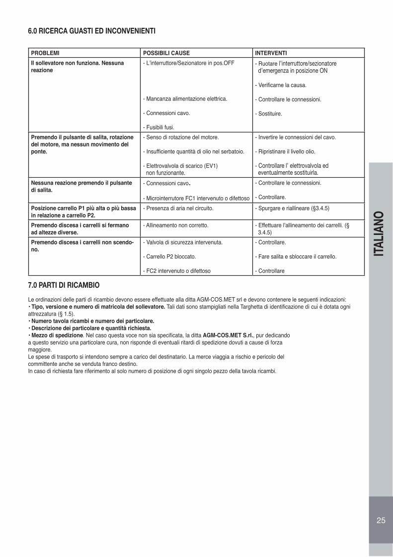
6.0 RICERCA GUASTI ED INCONVENIENTI
PROBLEMI POSSIBILI CAUSE INTERVENTIIl sollevatore non funziona. Nessuna reazione
- L’interruttore/Sezionatore in pos.OFF
- Mancanza alimentazione elettrica.
- Connessioni cavo.
- Fusibili fusi.
- Ruotare l’interruttore/sezionatore d’emergenza in posizione ON
- Verificarne la causa.
- Controllare le connessioni.
- Sostituire.
Premendo il pulsante di salita, rotazione del motore, ma nessun movimento del ponte.
- Senso di rotazione del motore.
- Insufficiente quantità di olio nel serbatoio.
- Elettrovalvola di scarico (EV1) non funzionante.
- Invertire le connessioni del cavo.
- Ripristinare il livello olio.
- Controllare l’ elettrovalvola ed eventualmente sostituirla.
Nessuna reazione premendo il pulsante di salita.
- Connessioni cavo.
- Microinterrutore FC1 intervenuto o difettoso
- Controllare le connessioni.
- Controllare.
Posizione carrello P1 più alta o più bassain relazione a carrello P2.
- Presenza di aria nel circuito. - Spurgare e riallineare (§3.4.5)
Premendo discesa i carrelli si fermanoad altezze diverse.
- Allineamento non corretto. - Effettuare l’allineamento dei carrelli. (§ 3.4.5)
Premendo discesa i carrelli non scendo-no.
- Valvola di sicurezza intervenuta.
- Carrello P2 bloccato.
- FC2 intervenuto o difettoso
- Controllare.
- Fare salita e sbloccare il carrello.
- Controllare
7.0 PARTI DI RICAMBIO
Le ordinazioni delle parti dì ricambio devono essere effettuate alla ditta AGM-COS.MET srl e devono contenere le seguenti indicazioni:• Tipo, versione e numero di matricola del sollevatore. Tali dati sono stampigliati nella Targhetta di identificazione dì cui è dotata ogni attrezzatura (§ 1.5).• Numero tavola ricambi e numero dei particolare.• Descrizione dei particolare e quantità richiesta.• Mezzo di spedizione. Nel caso questa voce non sia specificata, la ditta AGM-COS.MET S.rl., pur dedicandoa questo servizio una particolare cura, non risponde di eventuali ritardi dì spedizione dovuti a cause di forzamaggiore.Le spese di trasporto si intendono sempre a carico del destinatario. La merce viaggia a rischio e pericolo delcommittente anche se venduta franco destino.In caso di richiesta fare riferimento al solo numero di posizione di ogni singolo pezzo della tavola ricambi.
26
ENGL
ISH
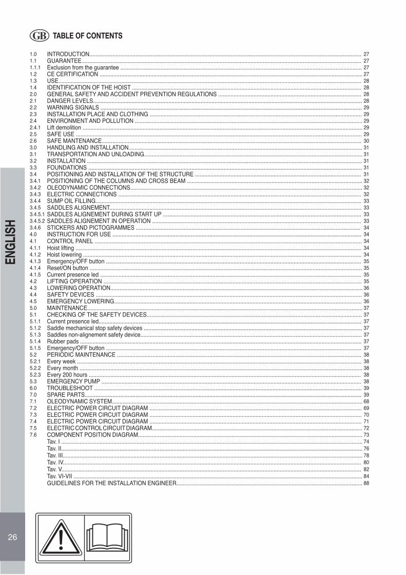
TABLE OF CONTENTS
1.0 INTRODUCTION................................................................................................................................................................................. 271.1 GUARANTEE...................................................................................................................................................................................... 271.1.1 Exclusion from the guarantee ............................................................................................................................................................. 271.2 CE CERTIFICATION ........................................................................................................................................................................... 271.3 USE..................................................................................................................................................................................................... 281.4 IDENTIFICATION OF THE HOIST ..................................................................................................................................................... 282.0 GENERAL SAFETY AND ACCIDENT PREVENTION REGULATIONS ............................................................................................. 282.1 DANGER LEVELS............................................................................................................................................................................... 282.2 WARNING SIGNALS .......................................................................................................................................................................... 292.3 INSTALLATION PLACE AND CLOTHING .......................................................................................................................................... 292.4 ENVIRONMENT AND POLLUTION .................................................................................................................................................... 292.4.1 Lift demolition ...................................................................................................................................................................................... 292.5 SAFE USE .......................................................................................................................................................................................... 292.6 SAFE MANTENANCE......................................................................................................................................................................... 303.0 HANDLING AND INSTALLATION........................................................................................................................................................ 313.1 TRANSPORTATION AND UNLOADING.............................................................................................................................................. 313.2 INSTALLATION ................................................................................................................................................................................... 313.3 FOUNDATIONS .................................................................................................................................................................................. 313.4 POSITIONING AND INSTALLATION OF THE STRUCTURE ............................................................................................................ 313.4.1 POSITIONING OF THE COLUMNS AND CROSS BEAM .................................................................................................................. 323.4.2 OLEODYNAMIC CONNECTIONS....................................................................................................................................................... 323.4.3 ELECTRIC CONNECTIONS .............................................................................................................................................................. 323.4.4 SUMP OIL FILLING............................................................................................................................................................................. 333.4.5 SADDLES ALIGNEMENT.................................................................................................................................................................... 333.4.5.1 SADDLES ALIGNEMENT DURING START UP ................................................................................................................................. 333.4.5.2 SADDLES ALIGNEMENT IN OPERATION ........................................................................................................................................ 333.4.6 STICKERS AND PICTOGRAMMES .................................................................................................................................................. 344.0 INSTRUCTION FOR USE .................................................................................................................................................................. 344.1 CONTROL PANEL .............................................................................................................................................................................. 344.1.1 Hoist lifting .......................................................................................................................................................................................... 344.1.2 Hoist lowering ..................................................................................................................................................................................... 344.1.3 Emergency/OFF button ...................................................................................................................................................................... 354.1.4 Reset/ON button ................................................................................................................................................................................. 354.1.5 Current presence led .......................................................................................................................................................................... 354.2 LIFTING OPERATION ........................................................................................................................................................................ 354.3 LOWERING OPERATION.................................................................................................................................................................... 364.4 SAFETY DEVICES ............................................................................................................................................................................. 364.5 EMERGENCY LOWERING................................................................................................................................................................. 365.0 MAINTENANCE................................................................................................................................................................................... 375.1 CHECKING OF THE SAFETY DEVICES............................................................................................................................................ 375.1.1 Current presence led........................................................................................................................................................................... 375.1.2 Saddle mechanical stop safety devices .............................................................................................................................................. 375.1.3 Saddles non-alignement safety device................................................................................................................................................ 375.1.4 Rubber pads ....................................................................................................................................................................................... 375.1.5 Emergency/OFF button ...................................................................................................................................................................... 375.2 PERIODIC MAINTENANCE ............................................................................................................................................................... 385.2.1 Every week ......................................................................................................................................................................................... 385.2.2 Every month ........................................................................................................................................................................................ 385.2.3 Every 200 hours ................................................................................................................................................................................. 385.3 EMERGENCY PUMP ......................................................................................................................................................................... 386.0 TROUBLESHOOT .............................................................................................................................................................................. 397.0 SPARE PARTS.................................................................................................................................................................................... 397.1 OLEODYNAMIC SYSTEM................................................................................................................................................................... 687.2 ELECTRIC POWER CIRCUIT DIAGRAM .......................................................................................................................................... 697.3 ELECTRIC POWER CIRCUIT DIAGRAM .......................................................................................................................................... 707.4 ELECTRIC POWER CIRCUIT DIAGRAM .......................................................................................................................................... 717.5 ELECTRIC CONTROL CIRCUIT DIAGRAM......................................................................................................................................... 727.6 COMPONENT POSITION DIAGRAM.................................................................................................................................................. 73
Tav. I .................................................................................................................................................................................................... 74Tav. II.................................................................................................................................................................................................... 76Tav. III................................................................................................................................................................................................... 78Tav. IV.................................................................................................................................................................................................. 80Tav. V................................................................................................................................................................................................... 82Tav. VI-VII ............................................................................................................................................................................................ 84 GUIDELINES FOR THE INSTALLATION ENGINEER......................................................................................................................... 88
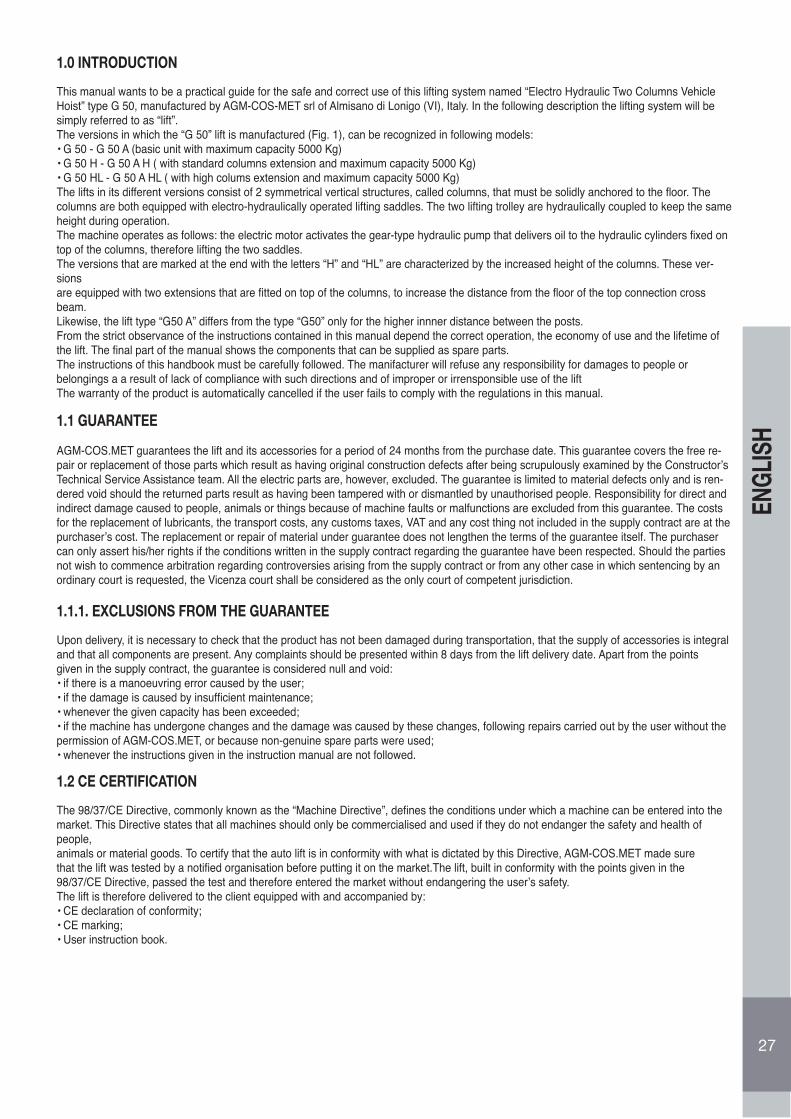
27
ENGL
ISH
1.0 INTRODUCTION
This manual wants to be a practical guide for the safe and correct use of this lifting system named “Electro Hydraulic Two Columns VehicleHoist” type G 50, manufactured by AGM-COS-MET srl of Almisano di Lonigo (VI), Italy. In the following description the lifting system will besimply referred to as “lift”.The versions in which the “G 50” lift is manufactured (Fig. 1), can be recognized in following models:• G 50 - G 50 A (basic unit with maximum capacity 5000 Kg)• G 50 H - G 50 A H ( with standard columns extension and maximum capacity 5000 Kg)• G 50 HL - G 50 A HL ( with high colums extension and maximum capacity 5000 Kg)The lifts in its different versions consist of 2 symmetrical vertical structures, called columns, that must be solidly anchored to the floor. Thecolumns are both equipped with electro-hydraulically operated lifting saddles. The two lifting trolley are hydraulically coupled to keep the sameheight during operation.The machine operates as follows: the electric motor activates the gear-type hydraulic pump that delivers oil to the hydraulic cylinders fixed ontop of the columns, therefore lifting the two saddles.The versions that are marked at the end with the letters “H” and “HL” are characterized by the increased height of the columns. These ver-sionsare equipped with two extensions that are fitted on top of the columns, to increase the distance from the floor of the top connection crossbeam.Likewise, the lift type “G50 A” differs from the type “G50” only for the higher innner distance between the posts.From the strict observance of the instructions contained in this manual depend the correct operation, the economy of use and the lifetime ofthe lift. The final part of the manual shows the components that can be supplied as spare parts.The instructions of this handbook must be carefully followed. The manifacturer will refuse any responsibility for damages to people orbelongings a a result of lack of compliance with such directions and of improper or irrensponsible use of the liftThe warranty of the product is automatically cancelled if the user fails to comply with the regulations in this manual.
1.1 GUARANTEE
AGM-COS.MET guarantees the lift and its accessories for a period of 24 months from the purchase date. This guarantee covers the free re-pair or replacement of those parts which result as having original construction defects after being scrupulously examined by the Constructor’sTechnical Service Assistance team. All the electric parts are, however, excluded. The guarantee is limited to material defects only and is ren-dered void should the returned parts result as having been tampered with or dismantled by unauthorised people. Responsibility for direct and indirect damage caused to people, animals or things because of machine faults or malfunctions are excluded from this guarantee. The costs for the replacement of lubricants, the transport costs, any customs taxes, VAT and any cost thing not included in the supply contract are at the purchaser’s cost. The replacement or repair of material under guarantee does not lengthen the terms of the guarantee itself. The purchaser can only assert his/her rights if the conditions written in the supply contract regarding the guarantee have been respected. Should the parties not wish to commence arbitration regarding controversies arising from the supply contract or from any other case in which sentencing by an ordinary court is requested, the Vicenza court shall be considered as the only court of competent jurisdiction.
1.1.1. EXCLUSIONS FROM THE GUARANTEE
Upon delivery, it is necessary to check that the product has not been damaged during transportation, that the supply of accessories is integraland that all components are present. Any complaints should be presented within 8 days from the lift delivery date. Apart from the pointsgiven in the supply contract, the guarantee is considered null and void:• if there is a manoeuvring error caused by the user;• if the damage is caused by insufficient maintenance;• whenever the given capacity has been exceeded;• if the machine has undergone changes and the damage was caused by these changes, following repairs carried out by the user without thepermission of AGM-COS.MET, or because non-genuine spare parts were used;• whenever the instructions given in the instruction manual are not followed.
1.2 CE CERTIFICATION
The 98/37/CE Directive, commonly known as the “Machine Directive”, defines the conditions under which a machine can be entered into themarket. This Directive states that all machines should only be commercialised and used if they do not endanger the safety and health of people,animals or material goods. To certify that the auto lift is in conformity with what is dictated by this Directive, AGM-COS.MET made surethat the lift was tested by a notified organisation before putting it on the market.The lift, built in conformity with the points given in the98/37/CE Directive, passed the test and therefore entered the market without endangering the user’s safety.The lift is therefore delivered to the client equipped with and accompanied by:• CE declaration of conformity;• CE marking;• User instruction book.
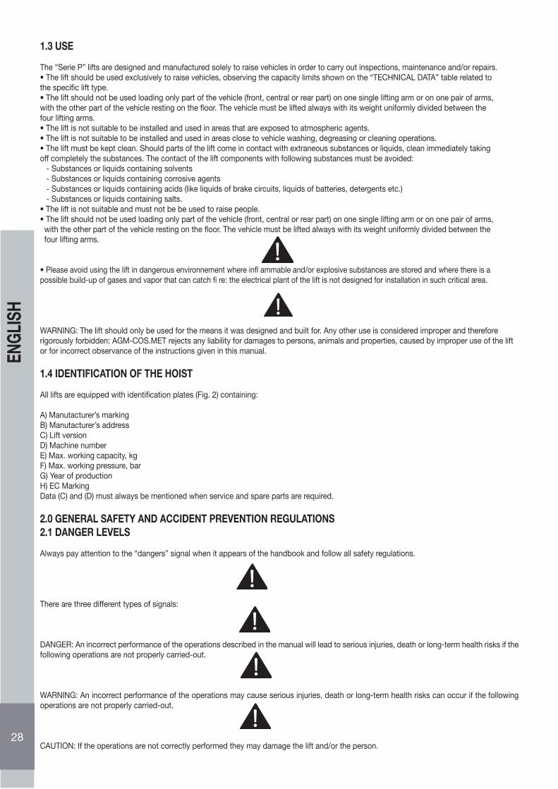
1.3 USE
The “Serie P” lifts are designed and manufactured solely to raise vehicles in order to carry out inspections, maintenance and/or repairs.• The lift should be used exclusively to raise vehicles, observing the capacity limits shown on the “TECHNICAL DATA” table related to the specific lift type.• The lift should not be used loading only part of the vehicle (front, central or rear part) on one single lifting arm or on one pair of arms, with the other part of the vehicle resting on the floor. The vehicle must be lifted always with its weight uniformly divided between the four lifting arms.• The lift is not suitable to be installed and used in areas that are exposed to atmospheric agents.• The lift is not suitable to be installed and used in areas close to vehicle washing, degreasing or cleaning operations.• The lift must be kept clean. Should parts of the lift come in contact with extraneous substances or liquids, clean immediately taking off completely the substances. The contact of the lift components with following substances must be avoided: - Substances or liquids containing solvents - Substances or liquids containing corrosive agents - Substances or liquids containing acids (like liquids of brake circuits, liquids of batteries, detergents etc.) - Substances or liquids containing salts.• The lift is not suitable and must not be be used to raise people.• The lift should not be used loading only part of the vehicle (front, central or rear part) on one single lifting arm or on one pair of arms, with the other part of the vehicle resting on the floor. The vehicle must be lifted always with its weight uniformly divided between the four lifting arms.
• Please avoid using the lift in dangerous environnement where infl ammable and/or explosive substances are stored and where there is apossible build-up of gases and vapor that can catch fi re: the electrical plant of the lift is not designed for installation in such critical area.
WARNING: The lift should only be used for the means it was designed and built for. Any other use is considered improper and thereforerigorously forbidden: AGM-COS.MET rejects any liability for damages to persons, animals and properties, caused by improper use of the liftor for incorrect observance of the instructions given in this manual.
1.4 IDENTIFICATION OF THE HOIST
All lifts are equipped with identification plates (Fig. 2) containing:
A) Manutacturer’s markingB) Manutacturer’s addressC) Lift versionD) Machine numberE) Max. working capacity, kgF) Max. working pressure, barG) Year of productionH) EC MarkingData (C) and (D) must always be mentioned when service and spare parts are required.
2.0 GENERAL SAFETY AND ACCIDENT PREVENTION REGULATIONS2.1 DANGER LEVELS
Always pay attention to the “dangers” signal when it appears of the handbook and follow all safety regulations.
There are three different types of signals:
DANGER: An incorrect performance of the operations described in the manual will lead to serious injuries, death or long-term health risks if the following operations are not properly carried-out.
WARNING: An incorrect performance of the operations may cause serious injuries, death or long-term health risks can occur if the following operations are not properly carried-out.
CAUTION: If the operations are not correctly performed they may damage the lift and/or the person.28
ENGL
ISH
CAUTION: If the operations are not correctly performed they may damage the lift and/or the person.
WARNING: Please read the instructions carefully: anyone failing to do so may suffer irreparable damages or cause them to people, animals or things. AGM-CO.SMET Srl refuses any responsability for damages that may occur due to a lack of compliance with the satety and prevention regulations illustrated here.AGM-CO.SMET Srl also refuses responsibililty for damages due to an improper use of the lift or to unauthorized modifications.
2.2 WARNING SIGNALS
The safety signals (Figure 3) described in this manual are also placed on the lift; they indicate dangerous and unsafe situations.The labels should be kept clean and should be replaced immediately if they are damaged or begin to peel off.Carefully read the definitions of the safety signals and memorize them well:
1) It is mandatory that you carefully read the instruction manual before operating the lift. Before every maintenance operation it is mandatory to disconnect the power supply and carefully read the instruction manual.2) Danger of falling: do not get on the lift.3) Danger of crushing: do not get near the moving parts4) Danger of electrical shocks: the electrical panel is live; before any intervention, always disconnect the electrical power supply.
2.4 ENVIRONMENT AND POLLUTIONDo not use the lift to wash, take grease off motor-vehicles, sandblasting or grinding operations.As for the use and disposal of lift cleaning and maintenance products, users are required to comply with the regulations in force in their country. They are also advised to follow the indications given by the manufacturers of such products
2.4.1 DISMANTLING THE LIFTIf the lift is to be dismantled for demolishing or because it is not used, some precautions should be taken in order to avoid environmentalpollution risks:
• The oil, of the oleodynamic station, of the circuit and of the cylinders should be completely collected. (ELECTRO-MECHANICAL HOISTS ARE EXCLUDED)• Disassemble the lift components, and divide them into groups of similar material to ease differential destruction.• The hydraulic oil that has been used, the rubber parts and the metal scrap are classifi ed as special waste and should be eliminated or temporarily stored in accordance with the current anti-pollution laws of the country where the lift is being used. (ELECTRO-MECHANICAL HOISTS ARE EXCLUDED)
2.5 SAFETY PRESCRIPTIONS• Do not let anyone use the lift unless they are fully aware of all the regulations.• It is forbidden to allow activation of the lift by improperly trained or incompetent personnel, or personnel who are not in the good health conditions.• It is forbidden to touch or lean on the hoist’s moving parts, or to put oneself between the parts during the up or down maneuvers of the lift.• It is forbidden to lift persons, animals or objects: the lift has been built exclusively for lifting motor-vehicles.• It is forbidden to lift motor-vehicles with persons, animals or unstable objects inside.• Waiting, dwelling or passing under the raised motor-vehicle and around the lift by persons or animals is forbidden. This applies when the motorvehicle and lift are moved slightly, when the emergency/OFF push-button (19 Fig. 2) and when the mechanical safeties have not been connected.• It is forbidden to place objects on the lift’s arms, especially those objects which can cause harm to person or objects should they fall.• It is forbidden to overload the lift: use of the lift is allowed only and exclusively for lifting weights falling within the carrying capacity indicated on the table 1.4 “TECHNICAL DATA” .
2.3 INSTALLATION PLACE AND CLOTHING
Choose a suitable space to install the machine, in a safe working environment, evaluating carefully following aspects:
• The place must be safe, free from obstacles and protected from atmospheric agents. From the control desk the operator must be able to oversee the complete installation and the operation area and to see immediately the presence of unauthorized people or of obstacles that may cause danger.
• The minimum distance of the columns and of the danger area (Fig.4) from the walls of the building where the lift must be installed, should be of 70 cm at least.
• Lighting of the area should be good, but not dazzling and without too bright lights. The environment should be free of sources or working processes that may develop inflammable vapors or gases..
• Avoid wearing loose or flapping clothes when working, as they may get stuck in the lift moving parts.• As required by local norms in the country of installation of the lift, the operator will have to wear, apart from suitable clothing, additional accident protection
accessories like, for example: helmet, glasses, gloves, special shoes, etc.
29
ENGL
ISH
• It is forbidden to overload the lift: use of the lift is allowed only and exclusively for lifting weights falling within the load capacity indicated inthe table TECHNICAL DATA.• It is mandatory to place the motor-vehicles on the lift in a way that the weight is well distributed and centered; the doors must remain closed; no objects shall protrude out of the motor-vehicle’s outside dimensions; the motor-vehicle’s center of gravity must fall within the fourrests; when some of the motor-vehicle’s parts are disassembled, the center of gravity may move.
• It is forbidden to overload the lift. The use of the lift is permitted only and solely to raise loads within the maximum permissible capacitythat is listed in the “LOAD DISTRIBUTION” table (Fig. 5) and placing the vehicles on the lift in such a way as to comply, at the same time,with following regulations contained in the european norm EN 1493:1998:1. The weight of the vehicle to be lifted, represented by the addition of the 2 loads Q1 and Q2 (see the symbols in Fig. 5), must notexceed the maximum lift capacity (Qmax); i.e. (Q1+Q2) ≤ Qmax2. The maximum load Q1 (Q1max) placed indifferently on the short or on the long arms, must not exceed 3330 Kg as shown in Fig. 5,i.e. (Q1max ≤ 3330 Kg)
AGM Srl accepts no liability for injury or damage to persons, animals and belongings as a result of negligence to observe the aboveinstructions and/or for any use of the lift that is not described in this manual.
• It is mandatory to install the lift on a level, smooth and horizontal floor.• It is mandatory to install the lift close to a power socket and to connect it using a suitable plug in compliance with the country regulations.• It is mandatory to install the lift in a place protected from water, ice and wind.• It is mandatory that all the safety devices and the lift itself be thoroughly checked for their integrity before starting-up the lift.• It is mandatory that the motor-vehicle to be lifted is driven and moved only by personnel suited to driving as regulated by the laws in forcein the Country in which the lift is used.• It is mandatory to check that no foreign persons or animals are within or near the danger areas (Fig. 5) before starting-up the lift.• We recommend that you familiarize yourself with the control devices and their functions before beginning operation.• We recommend to pay careful attention when you raise the lift in order not to crush the motor-vehicle against the workshop’s ceiling, sincemotor-vehicles come in different sizes.• Before you raise the motor-vehicle, it is mandatory that you raise it first only 10 cm. as a test, thereby checking the load’s stability.• We recommend that before lowering the bridge, you check that no objects are around or underneath the motor-vehicle; in case, remove them.• It is obligatory to lower the bridge and rotate the Emergency cut-off switch (19 Fig.2) to the OFF position before leaving the workstation.• It is strictly forbidden to modify the hydraulic unit in any way whatsoever (17 Fig. 3).• It is mandatory that no equipment connected to the mains be present in the area above the lift. Electrical discharge could occur should thelift or the motor-vehicle collide with such equipment, causing danger to persons.• In the event of danger to persons, animals or property, rotate the Emergency cut-off switch (19 Fig.2) to the OFF position as quickly as possible.• If oil from the hydraulic unit comes in contact with the skin, we recommend that you wash the part with plenty of water and soap.• It is mandatory that you raise the lift high enough so that there is enough space to have access to the motor-vehicle and walk in an up-rightposition.• It is mandatory to carry out the saddles alignement before the start-up and, when in operation, after a few up and down cycles.• It is forbidden to work with the lift when, after a saddle alignement operation, the saddles are not perfectly aligned: the vehicle may fall down.• It is mandatory, in case of malfunction of the lift, to stop the operation and to contact the manufacturer or the authorized maintenance workshop.• It is forbidden to operate with the lift when during the use you notice malfunctions or anomalies.To clean the lift use only a soft cloth. It is allowed to wet lightly the cloth with alcool to clean oil and grease spots. Do not use other solvents as they may damage plastic components and painted parts.
2.6 SAFE MAINTENANCE
• It is mandatory to periodically inspect the integrity of the safety devices and of the structure of the lift.• It is mandatory to check periodically the fastening and sealing of screws, nuts and connectors.• It is mandatory to check that the mobile lifting devices (rollers, pins etc.), are in good condition and well lubricated.• Only use the types of oil that are recommended.• Spare parts must satisfy the requirements indicated by the manufacturer. Use original spare parts only.• It is mandatory that the lift and its single components may only be moved or lifted by means of ropes, chains, cables and lifting tools thatcomply with the regulations in force in the country where such operations are performed.• It is mandatory that the installation is carried out in such a way that the lift or the motor vehicle may not crush, hook or touch other objects,especially electric, water and gas systems.• Removing or tampering with satety devices is strictly prohibited.• It is mandatory that installation and maintenance of the lift be carried-out only by qualified personnel, following the directions written in this manual.• It is mandatory to plug out the power supply during all maintenance and repairing operations.• Carefully follow the instructions provided in this manual; only allow qualified staff to replace damaged or worn-out parts.• Do not weld, cut or bore on the lift structure.• It is mandatory to carry out adjustements or interventions on the lift only after disconecting the power supply.• If the instruction labels placed on the lift which indicate the necessary advice to avoid accidents are dirty, it is mandatory to clean them;when they are damaged or have been peeled off they must be changed immediately.• We recommend that you thoroughly clean the floor of oil spills as soon as they occur because they can be very dangerous.
30
ENGL
ISH
3.0 HANDLING AND INSTALLATION
3.1 TRANSPORTATION AND UNLOADING
WARNING: Unloading, transportation and lifting operations of the liftcan be dangerous if not carried-out with maximum attention.Therefore, move away any persons unrelated to the task; clean, clear away and delimit the area of installation; check that the means to be used are suitable, complete and fully efficient; do not touch suspended loads and stay away from it within a safe distance; during transportation,the loads should not be raised higher than 20 cm. from the floor; carefully follow the directions below; if you have doubts or uncertainties, stop immediately.After unpacking the different parts of the lift, check that all components are complete and there are no damaged parts. In case of doubt, do not proceed with the assembling operation and call the manufacturer or the distributor.
Due to transportation and volume requirements, the bridge is sent partially dismantled into its main parts. The various components of thepackaged bridge are connected to each other with special rods for easy and safe transportation and handling. The packed lift should be moved using a forklift truck of suitable capacity. While moving, do not let the packed lift or the individual columns undergo knocks or blows. Thedimensions and weight of the packed lift are shown on Fig. 6.
The packing elements (plastic bags) polystyrene, nails, screws, wood, etc., should not be left around where kids may pick them up, as they are a potential cause of danger. Deliver such non-biodegradable materials to garbage collection points for disposal.
3.2 INSTALLATION
WARNING: Only let qualified and authorized technicians perform installation, control and inspection operations. They must be able to guarantee full compliance of these with the safety standards applicable to elestrotechnology, pneumatics and building.
DANGER: Installation, control and inspection of the lift may involve hazardous operations. As a consequence, directions must be followed carefully. Should any doubts persist, contact the manufacturer. AGM-COSMET Srl refuse any responsibility for damage to people or things due to a non-compliance with the safety and accident prevention regulations contained in this manual.
3.3 FOUNDATION
The hoist must be placed on a renforced concrete layer type “Rck 30” (3000 N/cm2) with a min. thickness of 20 cm and an extension of min. 1,5 m from the ancorage points.The cement base plate must be dead-bright, perfectly even and cast on solid ground. The overall dimensions of the plant are indica-ted in the figure 1.
3.4 POSITIONING AND INSTALLATION OF THE STRUCTURE
WARNING: In this phase of the installation, DO NOT connect any electric cables to the lift.
3.4.1 POSITIONING OF THE COLUMNS AND CROSS BEAM
1) Mark on the floor, at the proper distance and in perfect alignment, the position of the anchoring holes of the two columns (see Fig. 7).2) Using a 16 mm. drill bit, make all 16 anchoring holes on the floor for a depth of about 150 mm. (1 Fig. 7). Then clean thoghrougly the holes and the floor.3) Hook one of the columns to the bracket which is already mounted on the outer side of the column, using suitable lifting and slinging equipment (1 Fig. 8) as shown in Figure 8, and place it in its proper place.4) Insert the eight M16 external dowels (Type HILTI HSA-A M 16 x 190) (1 Fig. 7 and 1 Fig. 9), hitting them lightly with a hammer.5) Hook the other column and place it in its place; check that both columns are placed at the correct distance and that they are properly aligned with each other. You can check this by placing the upper crosspiece on the lifting saddles: the ends of the crosspiece must coincide with the open sides of the columns.6) Insert the 8 external dowels for this column, as well.7) Remove the brackets (1 Fig. 8) from the columns and keep them for future dismantling or new installation of the lift.8) The “G 50 H” and “G 50m HL” lift types are supplied with extensions for the columns (1 Fig. 10). The extensions are to be placed on the upper end of the columns and secured with the supplied screws as shown (2 Fig. 10).9) Fit now on the upper crossbeam (1 Fig. 11), the vehicle safety anti-collision rod (2 Fig. 11) as shown on Fig. 11, using the supplied screws.10) Using proper lifting and slinging equipment, lift the connecting crosspiece (1 Fig. 12). Place it between the two top ends of the columns and secure it with the supplied screws (2 Fig. 12)11) Fix the safety vehicle anti-collision limit switch (10 Fig. 12), using the supplied screws, to the crossbeam bracket as shown in Fig. 12, so that the safety pipe (11 Fig. 12) is placed under the limit switch lever. When the safety pipe is pushed upwards, it must activate the limit switch (Fig.12)
31
ENGL
ISH
12) Tighten the external dowels bolts (1 Fig. 7and 1 Fig. 9) with a torque wrench setting equal to100 Nm. If the bolts are idle, they should be replaced with larger size ones.
3.4.2 HYDRAULIC CONNECTIONS
WARNING. In this phase DO NOT carry aut electric connections on the lift.
CAUTION. Connecting the hydraulic systems correctly is of utmost importance.
• Connect the steel cross-pipe (3 Fig. 12) found inside the connecting crosspiece (1 Fig. 12) to their proper pipe fittings inside the two columns (3A Fig. 12). The “G 50 H” and “G 50 HL” types with column extensions are supplied with two pipe sections and their respective fittings to connect the column pipes to the crosspiece pipes.• Remove the rubber drain pipe (4 Fig. 12) from the column P2, pull it to the hydraulic unit and connect it there to its proper pipe fitting (7 Fig. 12).• Finally, check that all the fittings are well tightened.• Fix the cross-pipe (3 Fig. 12) in the centre of the connecting crosspiece, using the supplied clamps (15 Fig. 12).
3.4.3 ELECTRIC CONNECTIONS
CAUTION:
• The electric supply voltage must correspond to the one required by the control panel. • e electric panel must be connected with a main cut-off switch installed in compliance with the regulations of the country where the lift is used. • The supply system of the electric panel must be in compliance with such regulations too. • The minimum required power is 3 kW. • The minimum required electric cables section is 4 mm2. • Throughout this phase the motor should only work for a few seconds, in order to avoid damaging the hydraulic pump.
PROCEDURE:
• Connect the microswitch cable placed on the connecting crosspiece (5 Fig. 12) to the numbered terminal (6 Fig. 10) of column P1• Connect the column P2’s electromagnet cable to its numbered terminal on column P1. • Connect the power supply cable (14 Fig. 12) that comes out of column P1 to the mains. • Connection must be carried-out according to the regulations in force in the Country where the lift its being used
WARNING: Before going ahead with the next steps, read carefully the chapter 4.0 concerning the control panel and gain a good knowledge of the machine function by carrying out the different operations without loading the lift.
• Place the line under tension and check the Emergency cut-off switch (19 Fig.2) to make sure it is in the ON position (if necessary, rotate it).• Press and release the button “UP” (22 Fig. 2). Make sure that the motor is rotating in the same direction as indicated by the arrow (8 Fig. 12) printed on its base (clockwise looking from the top). If the rotative direction is not the same, disconnect power and change over the two wires on the terminal.
32
ENGL
ISH
3.4.4 SUMP OIL FILLING
WARNING: Always make sure there are no oil leaks; if necessary disconnect the electric power and tighten the loose connectors. How to lift the saddles:1) Unscrew the oil-sump plug (9 Fig.12) and pour into the tank (10 Fig. 12) 7 litres of hydraulic oil ESSO NUTO H32 or the equivalent (ISO VG 32).
2) Press the “UP” button (22 Fig .2) and keep it pressed until the saddle P1 has reached approx. 50 cm height.3) Position the arms (6 Fig. 2) close to the saddles (4 Fig. 2) so that the arms (6 Fig. 2) are mounted with the toe safety guards (14 Fig. 2)
facing away from the lift.4) Mount the two arms on the raised saddle using the pin (2 Fig. 14), locking it at the ends with two retaining rings (3 Fig. 14). Pay careful attention to place the
anti-rotation arm safeties (5 Fig. 14) properly when mounting them: the safeties must have the toothed sector towards the rack (4 Fig. 14) of each arm. By pulling the knob upwards (5 Fig. 14) you can temporarily exclude the anti-rotation arm safeties.
5) Press the “UP” push-button (22 Fig. 2) and continue pressing it until the saddle P1 reaches its maximum height. At this point, fill the tank up with 3 more litres of oil.
6) Press the UP button (22, fig. 2) again until Saddle P1 is at a height of approximately 50 cm.7) Fit the arms to the saddle of the column P2 repeating the operations indicated at point 4.8) Push again the “UP” button(20 Fig.2) until the saddle P2 reaches the maximum elevation. After this operation keep the button pressed for
10÷ 15 seconds to purge the air inside the system.
3.4.5 SADDLES ALIGNMENT
3.4.5.1 ALIGNEMENT BY START OF OPERATION
1) Press the DOWN push-button (23 Fig. 2) bringing down the saddles to the minimum height.
2) Press the “UP” button (22 Fig. 2) until both saddles reach the maximum height.3) After 5 ÷ 10 minutes of rest which allows the separation of any air within the oil, repeate the UP-DOWN cycle as shown in steps 1) and 2) to make sure that
the safety devices function properly as described in this manual.4) With completely lowered carriages, check the oil level and, if necessary, add more oil to reach the proper level, that is 2 ÷ 3 cm below the oil filling hole.
DANGER: beforer lifting any vehicle, after installation of the lift and after all maintenance work on the hydraulic system, it is mandatory to check the correct function of the saddles alignement safety device as described under 5.1.3.
The saddles alignement operation is very important to grant the correct function of the lift and the operator’s safety and should be carried out by qualified and responsible personnel only.
3.4.5.2 ALIGNEMENT DURING OPERATION
During the normal use the saddles alignement is maintained automatically by the oleodynamic system of the cylinders in series with the extravasation circuit. Notwithstanding it is compulsory to carry out the saddles alignement every time you notice a slight height difference between the two carriages, press the “UP” button (22 Fig. 2) until both carrages reach the maximum height. Keep the button pressed for a few seconds. (This operation is possible to make during the normal use with the vehicle loaded on the lift on condition that, the disalignment between carriages must be maxim 3÷4 cm). Then proceed with the lowering operation.
CAUTION: Durig this stage control that the carriages disalignment remains the same.
DANGER: it is forbidden to use the lift if, after the saddles alignement operation, the lifting arms are rapidly going out of alignement.
33
ENGL
ISH
3.4.6 STICKERS AND PICTOGRAMMES
Install on the lift all stickers that are supplied with this manual, following the layout of fig. 3.
WARNING: if the stickers are not installed on the lift, the guarantee conditions are no longer valid and the Manufacturer is relieved of any responsibility for damages caused by the use of the lift.
Damaged, deteriorated and illegible or missing stickers should be replaced immediately. Ask the Seller for replacement stickers, specifying the position number shown on fig. 3 and install the new stickers in the correct position on the lift as soon as possible.
4.0 INSTRUCTIONS FOR USE
WARNING. Read carerully the chapters concerning ‘Satety regulations and accidents preventions”
WARNING. Before touching the control board for any operation, check that nobody is close to the lift.
4.1 CONTROL PANEL
The following operations can be carried out from the control panel:
4.1.1 LIFTING
• Check to make sure the Emergency cut-off switch (19 Fig. 2) is in the raised position (if necessary, rotate it)• Press the RAISE button (21 fig. 3) until the desired height is reached.
Upon release of the raise button, the elevator performs the phase of AUTOMATIC POSITIONING of the trolleys, thus permitting them to descend and the mechanical safety devices to be engaged.
Important: The AUTOMATIC STANDING sequence, will not work and will be excluded, releasing the UP pushbutton (22 Fig. 2) when the lower corner of the carriage (Fig. 14) is not higher than 20 cm from the floor. This will allow the immediate carriages stop during the delicate starting phase of lift raising.
WARNING: Before starting the raising operation, read carefully the instructions of chapter 4.2 LIFTING OPERATIONS.
4.1.2 LOWERING
Press the DOWN push-button (23 Fig. 2) bringing down the saddles to the desired height.
• In pressing the LOWER button (22 Fig. 3), the trolleys are raised for a short distance, thus permitting the mechanical safety devices to unhook themselves, and will then continue descent for as long as the button is held down. • Upon release of the LOWER button, the elevator performs the phase of AUTOMATIC POSITIONING of the trolleys, thus permitting them to descend and the mechanical safety devices to be engaged.
IMPORTANT: The AUTOMATIC STANDING sequence, will not work and will be excluded, releasing the DOWN pushbutton (23 Fig. 2), when the carriage (Fig. 14), lowering from up to down, has reached a height of approx. 20 cm from the floor.
34
ENGL
ISH
4.1.3 EMERGENCY SELECTOR SWITCH / OFF• Turning the Emergency Selector Switch (18 Fig. 2) to the “0” (OFF) position, the lift stops functioning completely.• This operation must always be done before approaching the working area under the lift.• Turning the Emergency Selector Switch to the “1” (ON) position, the functions of the lift are enabled.electrical feed circuit, there is no risk because the HOIST is equipped with sectioning devices of the electrical feed that isolate the machine.Furthermore, the raise and lower controls are of the “operator present” type (manually maintained action). Therefore, in the case of a fault in the electrical feed circuit it is not possible to switch the machine on, to impede the stopping of the machine if the command has already been given by the selector switch, that the load can fall or a drop in the efficiency of the protection devices. The parts that move during the raise or lower movements are therefore always stopped if there is a fault in the electrical feed circuit. On resetting the electrical feed circuit there are no risk situations because each movement of the hoist must be actuated manually by the operator using the “manually maintained action” control selector switch.
WARNING: It is compulsory to turn the Emergency Selector Switch (18 Fig. 2) to the “0” (OFF) position before entering the work zone underneath the lift.
WARNING: Before leaving the hoist unattended, the operator MUST turn the emergency selector switch (18 Fig. 2) to the 0 (OFF) position and mechanically block the rotating movement by inserting a lock (NOT supplied as standard equipment with the hoist) in the appropriate hole.
4.1.5 CURRENT PRESENCE LED• The current presence led (17 Fig.2) is illuminated when the reset/ON button activates all lift control functions.
WARNING: Do not appreach the lift when the current presence led (POWER) is on.
4.1.6 EXCLUSION OF AUTOMATIC PARKINGContemporarely pressing the Exclusion Automatic Parking Button (23 Fig. 2) and the UP (21 Fig. 2) or DOWN (22 Fig. 2) buttons, the operation of automatic parking is avoided.
This function will remain active for approximately 7 seconds, after which it will return to the automatic standing status.
WARNING: Do not approach hoist when the current presence led (POWER) is on.
4.2 LIFTlNG OPERATIONS
Follow these points:
• It is mandatory to place the motor-vehicles on the lift in a way that the weight is well distributed and centered; the doors must remainclosed; no objects shall protrude out of the motor-vehicle’s outside dimensions; the motor-vehicle’s center of gravity must fall within thefour rests; when some of the motor-vehicle’s parts are disassembled, the center of gravity may move.• It is forbidden to overload the lift. The use of the lift is permitted only and solely to raise loads within the maximum permissible capacitythat is listed in the “LOAD DISTRIBUTION” table (Fig. 5) and placing the vehicles on the lift in such a way as to comply, at the same time,with following regulations contained in the european norm EN 1493:1998:1. The weight of the vehicle to be lifted, represented by the addition of the 2 loads Q1 and Q2 (see the symbols in Fig. 5), must notexceed the maximum lift capacity (Qmax); i.e. (Q1+Q2) ≤ Qmax2. The maximum load Q1 (Q1max) placed indifferently on the short or on the long arms, must not exceed 3330 Kg as shown in Fig. 5,i.e. (Q1max ≤ 3330 Kg)
• AGM Srl accepts no liability for injury or damage to persons, animals and belongings as a result of negligence to observe the above instructions and/or for any use of the lift that is not described in this manual
• Push the Emergency cut-off switch (19 Fig. 2)• Check that the arms are turned in order not to hinder the entrance of the vehicle between the columns.• Place the vehicle so that it is positioned and cerntered in relation to the lift columns.• Turn the arms and take out the extensions so that the rubber pads are placed at the points provided by the car manufacturer for the vehicle lifting.
WARNING: Before raising the vehicle you must always check that the distribution of the loads in comparison to the vehicle’s masscomply with the LOAD DISTRIBUTION table (Fig. 5). If the values compared do not fall within the limits of the LOAD DISTRIBUTION table, do not raise the vehicle.
• Turn the Emergency cut-off switch (19 Fig.2) as indicated by the arrow and bring it in raised position.• Push the reset/ON button (20 Fig. 2).• Lift the vehicle about 10 cm.• Check the correst inserting of the rubber pads.• Check the vehicle stability.• Lift the vehicle.• Push the “Up” button (22 Fig. 2 -see 4.1.1-).• Push and lock the Emergency cut-off switch (19 Fig. 2) before entering the lift area. 35
ENGL
ISH
4.3 LOWERING OPERATIONS
Follow these instructions:
• Press the emergency cut-off switch (23 Fig. 2) bringing down the saddles to the minimum height.
• Press the CARRIAGE ALIGNEMENT pushbutton (24 Fig. 2) until both saddles reach the maximum height.• After 5 ÷ 10 minutes of rest which allows the separation of any air within the oil, repeate the emergency cut-off switch cycle as shown in steps
1) and 2) to make sure that the safety devices function properly as described in this manual.• With completely lowered carriages, check the oil level and, if necessary, add more oil to reach the proper level, that is 2 ÷ 3 cm
below the oil filling hole.
4.4 SAFETY DEVICES
WARNING: Do not absolutely remove or tamper with these devices. They must be kept in full efficiency all the time:
• Toe safety devices applied to the arms (14 Fig. 2) prevent the squashing of the operators feet during the last phase of arms lowering.• Current presence led (21 Fig.2): when it is on, approaching the lift is no permitted.• Arms anti-rotation mechanical safety devices with automatic insertion (15 Fig. 2 and 1 Fig. 14): they do not permit, the rotation of the lifting
arms with the saddles lifted.• Mechanical anti-fall safety devices (1 Fig. 13): they block the saddle lowering in case of leak in the hydraulic system or break of the
mechanical lifting devices.• Safety valves (hydraulic diagram): They prevent the saddles from descending in case there is a sudden decrease in pressure in the hydraulic
circuit or the lowering of one single saddle in case the other one is not moving because of a mechanical blocking.• Emergency cut-off switch (19 Fig. 2): if pressed blocks the lift operation.• Auxiliary electric circuit in low tension: this circuit can not cause “electric shock”.• Vehicle anti-collision safety (16 Fig. 2 and 2 Fig. 11): it blocks the raising of the lift if the vehicle being raised is about to collide with the
upper crosspiece.• “Manned” control panel: attendance of operator is necessary to start all lift functions.
4.5 EMERGENCY LOWERING
WARNING: When the saddles carry-out an “emergency descent”, the mechanical fall-proof saddle safeties are excluded.Therefore the following operations must be carried out only:
• When the lift does not lower due to a damage in the electric system or to an electricity failure;• When it is strictly necessary;• By a qualified technician;• Delimiting the area around the lift and permitting access to the operator only.
Procedure for emergency lowering:
• Turn the Emergency Selector Switch (18 Fig. 2) to the OFF position.• If the lift is in the “STOP” position the safety devices will not open. The following operations will then be possible only if the lift is equipped
with a manual emergency pump to lift the saddles and release the mechanical safety stops.• Open the covers and manually operate the electromagnets (1 Fig. 13)to open the safety devices (2 Fig. 13).• For the manual lowerig operate as follows:
1) Proceed with the manual lowering of the hoist by completely removing the cover of the EV1 solenoid valve (17 Fig. 12) and slowly pressing the pin (12 Fig. 12) to lower the hoist.2) Finished the phase of descent, screw completely the cap (17 Fig. 14) and bring the wedges of the mechanical safety device (2 Fig. 13) back in starting position in each column P1,P2.
DANGER. Carry out with accuracy all operations of point 2.
CAUTION. When you have reset the normal operating of the lift, let the unloaded lift go up and down for 2 or 3 times and check the normalfunctioning of the safety devices as further described in point 5.1.
36
ENGL
ISH
5.0 MAINTENANCE
In the continuation are listed the different maintenance operations. A steady compliance with the here included instructions will grant regularperformances, working economy and a long lift lifetime.
CAUTION: Regular deadlines to carry out maintenance are only mentioned as an indication and refer to standard conditions of use. Any variations, such as a more or less dusty environment and frequency in use deeply influence such times. If the conditions are more severe, maintenance must be carried out more often. When replacing the oil use the same type as before.
5.1 CHECKING OF THE SAFETY DEVICES
WARNING. The following operations must be carried out by unloaded lift.
5.1.1 CURRENT PRESENCE LED1) Turn the emergency cut-off switch (19 Fig. 2) as indicated by the arrow and bring it in raised position.2) Push the reset/ON button (20 Fig. 2).3) Check that the current presence led (21 Fig. 2) is illuminated.
5.1.2 MECHANICAL ANTIFALL SAFETIES1) Lift the saddles completely by pressing the UP pushbutton (22 Fig. 2)2) Released the UP pushbutton (22 Fig. 2) and completed the phase of AUTOMATIC STANDING, check the inserting of the safeties after having removed the protection casings placed on the outer side of each column and pulling towards outside the two wedge control brackets (1 Fig. 23) connected to the electromagnet. If the brackets are blocked, this means that the safeties (2 Fig. 23) are inserted.
5.1.3 SADDLES NON-ALIGNEMENT SAFETY DEVICELift the saddles approx. 1 metre from the bottom and proceed as follows:
Checking of saddle P11) Insert under the saddle P1 a piece of wood (6 fig. 14) in order to block the lowering of the saddle.2) Press the “DOWN ” pushbutton (23 Fig. 2). When the saddle P1 rests on the wood block, also the saddle P2 should stop immediately afterwards.
DANGER: should the saddle P2 not stop, check the limit switch FC2 (1 fig. 15) fixed on the cylinder end of column P1. The activation of the FC2 limit switch is of the utmost importance for the correct lift operating safety. Check therefore the limit switch correct position and function (1 fig. 15) before resuming the normal use of the lift.
Checking of saddle P21) Insert under the saddle P2 a piece of wood (6 fig. 14) in order to block the lowering of the saddle.2) Press the “DOWN ” pushbutton (23 Fig. 2). When the saddle P2 rests on the wood block, also the saddle P1 should stop immediately afterwards.
If the saddle P1 does not stop, check the shut valve (7 hydraulic diagram), 2 Fig. 15. If necessary, clean it with compressed air - if it does not work, replace it.
5.1.4 RUBBER PADSCheck their good state and, if worn out or broken, replace them.
5.1.5 EMERGENCY/OFF BUTTON
1) Turn the emergency/OFF button (19 Fig. 2) as indicated by the arrow,and so bring it in raised position.2) Push either the “UP” or “DOWN” button.3) Simultaneously push the emergency/OFF button (19 Fig. 2): the saddles must stop.
37
ENGL
ISH
5.2 PERIODIC MAINTENANCE
5.2.1 EVERY WEEK
• Weekly ispect the safety devices as indicated in the handbook.
• How to check the hydraulic oil level:• Lower the saddies completely and check that the level corresponds to the indicator, 2 ÷ 3 cm below the hole (10 Fig. 12).• If necessary fill up trough the plug (9 Fig. 12) with hydraulic oil “ESSO NUTO H32” or the equivalent.
5.2.2 EVERY MONTH
• Check that the lift screw set is tightly sealed
• Check the hydraulic seal; tighten loosened connectors where necessary.• Check that the hydraulic hoses are in good state. Replace damaged parts with original components when necessary.• Check that the pivots, rollers, bushings, saddle-arms frame and their extensions are duly lubricated and in good conditions; if necessary,
replace the damaged parts with original components.
5.2.3 EVERY 200 HOURS OF LIFT RUNNING
• Replace the oil in the hydraulic system, discharging the old one out of the pump and clean the oil filter. Refer to the respective spare partstable enclosed in this manual for this operation.
A correct performance of these operations will totally come to the user’s advantage. The equipment will indeed be in perfect state when work is resumed.
5.3 EMERGENCY HYDRAULIC PUMP
By request it is possible to install an emergency hydraulic pump in case of electricity failures or (as described in paragraph 4.5 “Emergency lowering”) to solve problems caused by occasional blockages in the lowering system.
Please remember that AGM-COSMET Srl or its distributors are always available if assistance or spare parts are needed.
38
ENGL
ISH
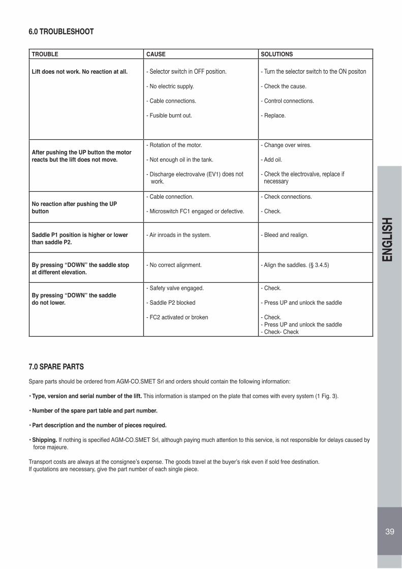
39
ENGL
ISH
6.0 TROUBLESHOOT
TROUBLE CAUSE SOLUTIONS
Lift does not work. No reaction at all. - Selector switch in OFF position.
- No electric supply.
- Cable connections.
- Fusible burnt out.
- Turn the selector switch to the ON positon
- Check the cause.
- Control connections.
- Replace.
After pushing the UP button the motorreacts but the lift does not move.
- Rotation of the motor.
- Not enough oil in the tank.
- Discharge electrovalve (EV1) does not work.
- Change over wires.
- Add oil.
- Check the electrovalve, replace if necessary
No reaction after pushing the UPbutton
- Cable connection.
- Microswitch FC1 engaged or defective.
- Check connections.
- Check.
Saddle P1 position is higher or lowerthan saddle P2.
- Air inroads in the system. - Bleed and realign.
By pressing “DOWN” the saddle stopat different elevation.
- No correct alignment. - Align the saddles. (§ 3.4.5)
By pressing “DOWN” the saddledo not lower.
- Safety valve engaged.
- Saddle P2 blocked
- FC2 activated or broken
- Check.
- Press UP and unlock the saddle
- Check.- Press UP and unlock the saddle- Check- Check
7.0 SPARE PARTS
Spare parts should be ordered from AGM-CO.SMET Srl and orders should contain the following information:
• Type, version and serial number of the lift. This information is stamped on the plate that comes with every system (1 Fig. 3).
• Number of the spare part table and part number.
• Part description and the number of pieces required.
• Shipping. If nothing is specified AGM-CO.SMET Srl, although paying much attention to this service, is not responsible for delays caused by force majeure.
Transport costs are always at the consignee’s expense. The goods travel at the buyer’s risk even if sold free destination.If quotations are necessary, give the part number of each single piece.

40
DEUT
SCH
INHALT
BEVOR MAN BEGINNT, MIT DER HEBEBÜHNE ZU ARBEITEN, SOLLT MAN AUFMERKSAMDIE ANWEISUNGEN LESEN, DIE IM VORLIEGENDEN HANDBUCH ENTHALTEN SIND.
1.0 EINLEITUNG................................................................................................................................................................................................. 411.1 GARANTIE .................................................................................................................................................................................................... 411.1.1 AUSSSCHLUSS AUS DER GARANTI.......................................................................................................................................................... 411.2 CE-MARKIERUNG ........................................................................................................................................................................................ 411.3 VERWENDUNG ............................................................................................................................................................................................ 421.4 BÜHNENKENNZEICHNUNG........................................................................................................................................................................ 422.0 ALLGEMEINE SICHERHEITS- UND UNFALLVERHÜTUNGS NO MEN...................................................................................................... 422.1 GEFAHRENGRADE ...................................................................................................................................................................................... 422.2 HINWEISSCHILDER ..................................................................................................................................................................................... 432.3 KLEIDUNG S................................................................................................................................................................................................... 432.4 UMWELT UND VERSCHMUTZUNG .............................................................................................................................................................. 432.4.1 ABBAU DER BÜHNE ..................................................................................................................................................................................... 432.5 SICHERER GEBRAUCH................................................................................................................................................................................ 432.6 SICHERE WARTUNG .................................................................................................................................................................................... 443.0 BEWEGUNG UND INSTALLATION................................................................................................................................................................ 453.1 TRANSPORT UND ABLADEN........................................................................................................................................................................ 453.2 AUFSTELLUNG.............................................................................................................................................................................................. 453.3 FUNDAMENTE.............................................................................................................................................................................................. 453.4 POSITIONIEREN UND MONTAGE DER STRUKTUR ................................................................................................................................. 453.4.1 POSITIONIERUNG DER SÄULEN UND DES QUERTRÄGERS................................................................................................................... 453.4.2 HYDRAULISCHE ANSCHLÜSS..................................................................................................................................................................... 463.4.3 ANSCHLÜSSE AN DAS ELEKTRISCHE NETZ............................................................................................................................................. 463.4.4 AUFFÜLLEN DER HYDRAULIKANLAGE ...................................................................................................................................................... 473.4.5 HUBSCHLITTEN-AUSRICHTUNG..................................................................................................................................................................473.4.5.1 HUBSCHLITTEN-AUSRICHTUNG BEI DER INBETRIEBNAHME.................................................................................................................. 473.4.5.2 HUBSCHLITTEN-AUSRICHTUNG IN BETRIEB............................................................................................................................................. 473.4.6 AUFKLEBER UND SCHILDER ..................................................................................................................................................................... 484.0 GEBRAUCHSANWEISUNGEN....................................................................................................................................................................... 484.1 BEDIENFELD................................................................................................................................................................................................. 484.1.1 HEBEN DER BÜHNE...................................................................................................................................................................................... 484.1.2 SENKEN DER BÜHNE................................................................................................................................................................................... 484.1.3 NOTSTOPTASTE/OFF.................................................................................................................................................................................... 494.1.4 RESETTASTE/ON ......................................................................................................................................................................................... 494.1.5 STROMLEUCHTANZEIGE ............................................................................................................................................................................. 494.2 PROCEDURA DI SOLLEVAMENTO.............................................................................................................................................................. 494.3 PROCEDURA PER LA DISCESA................................................................................................................................................................... 504.4 DISPOSITIVI DI SICUREZZA......................................................................................................................................................................... 504.5 DISCESA DI EMERGENZA ........................................................................................................................................................................... 505.0 MANUTENZIONE .......................................................................................................................................................................................... 515.1 VERIFICA DEI DISPOSITIVI DI SICUREZZA ............................................................................................................................................... 515.1.1 AUSSCHALTEN DER AUTOMATISCHEN STANDPOSITION....................................................................................................................... 515.1.2 HEBEN VON KRAFTHARZEUGEN ............................................................................................................................................................. 515.1.3 SENKEN VON KRAFTHARZEUGEN............................................................................................................................................................. 515.1.4 SICHERHEITSVORRICHTUNGEN................................................................................................................................................................ 515.1.5 SENKEN IM NOTFALL ................................................................................................................................................................................... 515.2 MANUTENZIONE PERIODICA ..................................................................................................................................................................... 525.2.1 WARTUNG ................................................................................................................................................................................................... 525.2.2 ÜBERPRÜFUNG DER SICHERHEITSVORRICHTUNGEN......................................................................................................................... 525.2.3 STROMLEUCHTANZEIGE . ......................................................................................................................................................................... 525.3 MECHANISCHE SICHERHEITSVORR. FÜR DAS ANHALTEN DER HUBSCHLITTEN.............................................................................. 526.0 SICHERHEITSVORRICHTUNG DER HUBSCHLITTEN-AUSRICHTUNG ................................................................................................... 537.0 PUFFER MIT GUMMIAUFLAGEN ............................................................................................................................................................... 537.1 NOTSTOPTASTE/OFF ................................................................................................................................................................................ 637.2 REGELMÄSSIGE WARTUNG....................................................................................................................................................................... 647.3 JEDE WOCHE .............................................................................................................................................................................................. 657.4 MONATLICH ................................................................................................................................................................................................. 667.5 ALLE 200 BETRIEBSSTUNDEN.................................................................................................................................................................... 677.6 FEHLERSUCHE ........................................................................................................................................................................................... 68
Tav. I .............................................................................................................................................................................................................. 69Tav. II.............................................................................................................................................................................................................. 70Tav. III............................................................................................................................................................................................................. 71Tav. IV............................................................................................................................................................................................................. 72Tav. V.............................................................................................................................................................................................................. 73Tav. VI-VII ...................................................................................................................................................................................................... 74ANLEITUNGEN FÜR DEN MONTAGETECHNIKER...................................................................................................................................... 92
4.3 LOWERING OPERATIONS
Dieses Handbuch beinhaltet die Anleitungen zur Installation, Bedienung und Wartung der “ZWEISÄULEN ELEKTROHYDRAULISCHEN HEBEBÜHNEN” der Serie G 5O, hergestellt von AGM-COS.MET srl aus Almisano di Lonigo (VI) Italien. In der nachfolgende Beschreibung wirddas Hebegerät immer einfach “Bühne” genannt.Die Bühnen der Serie “G 50” schliessen verschiedene Typen ein (Abb. ) und diese unterscheiden sich in folgenden Ausfuhrungen:• G 50 - G 50 A (Grundausführung mit maximaler Tragfähigkeit 5000 Kg)• G 50 H - G 50 A H (Modell mit verlängerten Standard-Säulen, maximale Tragfähigkeit 5000 Kg)• G 50 HL - G 50 A HL (Modell mit verlängerten Hoch-Säulen, maximale Tragfähigkeit 5000 Kg).
Die Hebebühne, in den verschiedenen Ausführungen, besteht aus zwei senkrechten, symmetrischen Säulen, die fest mit dem Boden verbunden werden. Die Säulen sind mit zwei elektrohydraulisch angetriebenen Hubwagen ausgestattet. Diese sind hydraulisch gekuppelt, um während der Arbeitsphasen den Gleichlauf zu garantieren. Der Betrieb der Maschine erfolgt durch einen Elektromotor. Dieser treibt eine hydraulische Pumpe an, die Öl zu den am oberen Teil der Säulen befestigten Hebezylinder schickt und damit die beiden Wagen hebt. Die Ausführungen gekennzeichnet am Ende der Bezeichnung mit “H” und “HL”, sind mit höheren Säulen ausgerüstet. Diese Ausführungen haben zwei Verlängerungen auf den Standardsäulen um die Höhe des Querbalkens vom Boden zu erhöhen. Die Ausführungen gekennzeichnet “G50A” unterscheiden sich vom Modell “G50” nur für den grösseren Abstand zwischen der Säulen. Die korrekte Arbeitsweise, Wirtschaftlichkeit und Lebensdauer der Hebebühne hängt von der Einhaltung der in diesem Handbuch aufgeführtenAnleitungen ab. Im letzten Teil des Handbuch werden die lieferbaren Ersatzteile aufgeführt. Es ist unbedingt notwendig, die Anleitungen in diesem Handbuch zu beachten: der Hersteller weist jede Haftung bei Nichtbeachtung dieser Anleitung oder für jede unzulässige oder fahrlässige Benutzung der Bühne zurück. Die Nichtbeachtung der in diesem Handbuch enthaltenen Anleitungen führt zum automatischen Verfall der Garantie
1.1 GARANTIE
AGM-COS.MET garantiert die Bühne und dessen Zubehöre für 24 Monate ab Auslieferungsdatum. Die Garantie schliesst die Reparatur oder Austausch von alle Teile welche, nach sorgfaltiger Überprüfung seitens der Kundendiestabteilung des Herstellers, nachweislich Herstellungsfehler aufweisen. Alle Elektroteile sind ausgeschlossen. Die Garantie ist auf die defekten Materialien begrenzt und kann nicht in Anspruch genommen werden falls die zurückgesandten Teile modifiziert wurden oder von nicht berechtigten Personal ausgebaut wurden. Ausgeschlossen von der Garantie ist auch die Haftung für direkte oder indirekte Schäden an Personen, Tiere oder Sachen welche auf schechte Funktion oder Defekt der Maschine zurückzuführen sind. Ölwechseln, Transporte, Einführungszoll, Mehrwertsteuer und alle sonstige Kosten welche nicht ausdrücklich im Vertrag angegeben sind, verstehen sich in jedem Falle zu Lasten des Käufers.Der Austausch von Teilen in Garantie verlängert auf keinem Fall die Garantiezeit. Der Käufer kann die Garantierechte in Anspruch nehmen nur wenn alle Garantiebedingungen erfüllt sind, mit Beziehung ggf. auf seinen spezifischen Kaufvertrag.Allein das Tribunal von Vicenza ist zuständig für alle Streitigkeiten welche in Zusammenhang mit dem Vertrag stehen, falls diese nicht durch Arbitrat geregelt werden können, oder in alle Fälle wo eine legale Entscheidung notwendig ist.
1.1.1 AUSSSCHLUSS AUS DER GARANTIE
Bei der Auslieferung ist es notwendig zu Uberprüfen, daß die Ware keine Transportschäden aufweist und daß alle Zubehöre mitgeliefert wurden. Reklamationen müssen binnen 8 Tage vom Auslieferungsdatum der Bühne erfolgen.Ausser den Fällen die im Kaufvertrag festgelegt sind, die Garantie is nicht gültig wenn:
• Falsche Handhabung oder Bedienungsfehler
• Schäden die auf mangelnde Wartung zurückzuführen sind.
• Überschreitung der zugelassene Tragfähigkeit.• Schäden welche auf Modifizierungen der Maschine, Selbst-Reparaturen ohne Genehmigung von AGM-COS.MET, Einbau von
frem den Ersatzteile, zurueckzuführen sind.• Nichteinhaltung der hier angegebenen Anweisungen.
1.2 CE-ZERTIFIZIERUNG
Die Richtlinie 98/37/CE, auch unter “Maschinenbau-Richlinie” bekannt, definiert die Bedingungen unter welchen eine Maschine auf dem Markt gebracht werden kann. Diese Richtlinie schreibt vor, daß jede Art von Maschine nur dann verkauft und in Betrieb genommen werden kann,wenn diese keine Gefahr für die Sicherheit von Personen, Tieren oder Sachen darstellt. Vor dem Verkaufsfreigabe der Bühne und um die Ubereinstimmung mit dem oben genannten Richtlinien zu beweisen, hat AGM-COS.MET eine unabhängige Zertifikationsbüro beauftragt, die Überprüfung einer Maschine durchzuführen. Die Bühne, hergestellt nach den 98/37/Ce Richtlinie, hat mit Erfolg die Überprüfung bestanden und kann somit, ohne Gefahr für den Benutzer, eingesetzt werden.Die Bühne wird geliefert komplett mit:
• CE Übereinstimmungs-Erklärung
• CE Kennzeichnung
• Bedienungsanleitung
Die Bühne ist zum Heben von Personen nicht geeignet. 41
DEUT
SCH
1.3 VERWENDUNG
Die Heber der Serie “G 50” sind ausschließlich für die Hebung von Kraftfahrzeugen zur Inspektion, Wartung und/oder Reparatur dieserKraftfahrzeuge entwickelt und gebaut worden.• Die Bühne darf ausschließlich für die Hebung von Fahrzeugen verwendet werden, dabei müssen die Tragfähigkeitsgrenzen immer beachtet werden.• Die Bühne ist für die Aufstellung und Betrieb im Freien nicht geeignet..• Die Bühne soll nicht in der Nähe von Fahrzeugswaschanlagen, Entfettungs- und Reinigungsplätzte, aufgestellt und betrieben werden.• Die Hebebühne muss sauber gehalten werden. Im Falle, dass Teile des Hebers mit fremden Substanzen und/oder mit fremden
Flüssigkeiten in Kontakt kommen, sollten diese unverzüglich gereinigt werden, indem man die fremde Substanz vollständig entfernt.Insbesondere muss der Kontakt der Heberteile mit folgenden Substanzen verhindert werden:- Substanzen und/oder Flüssigkeiten, die Lösungsmittel enthalten,- Substanzen und/oder Flüssigkeiten, die korrodierende Mittel enthalten,- Substanzen und/oder Flüssigkeiten, die Säuren enthalten (wie zum Beispiel Flüssigkeit für Bremskreise, Detergentwirkstoffe,Flüssigkeiten für Batterien usw.),• Substanzen und/oder Flüssigkeiten, die Salze enthalten.• Der Heber ist nicht für die Hebung von Personen vorgesehen.• Die Bühne darf nicht so verwendet werden, dass nur ein Teil des Fahrzeugs auf nur einen oder zwei Hebe-Armen aufgeladen wird(Vorder-, Mittel- oder Hinterteil), während der restliche Teil des Farhzeugs auf dem Boden bleibt. Das Fahrzeug muss immer mit einerregelmässigen Gewichtsverteilung auf die vier Hebe-Armen aufgehoben werden.
• Die Bühne soll nie in eine gefährliche Umgebung wo sich brennbare und/oder explosive Werkstoffe befinden, oder wo sich anzündbare Gase und Dämpfe entwickeln können, benützt werden : die Elektroanlage der Bühne ist für solche Umgebungen nicht geeignet.
WARNUNG: Der Heber darf ausschließlich für den Gebrauch bestimmt werden, für den er entwickelt und gebaut wurde. Jegliche andere Verwendung, die im vorliegenden Handbuch nicht enthalten ist, ist unsachgemäß und somit ausdrücklich verboten: Die AGM-COSMET enthält sich jeglicher Verantwortlichkeit für Schäden an Personen, Tieren oder Gegenständen, die durch einen unsachgemäßen Gebrauch des Hebers oder durch die Nichtbeachtung der im vorliegenden Handbuch enthaltenen Anleitungen verursacht wurden.
1.4 BÜHNENKENNZEICHNUNGJede Bühne ist mit einem Typenschild versehen (25 Abb. .2 und 7 Abb. 3), welches folgenden Angaben enthält:
A) Warenzeichen des HerstellesB) Name und Anschrift des HerstellersC) BühnentypD) SeriennummerE) Maximale Tragfähigkeit, KgF) Maximaler Betriebsdruck, barG) BaujahrH) Warenzeichen CE
Diese Angaben (C) und (D) müßen bei jeder Service- und Ersatzteil-Anfrage angegeben werden.
2.0 ALLGEMEINE SICHERHEITS- UND UNFALLVERHÜTUNGSNORMEN2.1 GEFAHRENGRADEDie in dieser Broschüre enthaltenen Gefahrenzeichen immer beachten, und alle Sicherheitsvorschriften einhalten.
Die Gefahrenzeichen sind in drei verschiedenen Stufen unterteilt:
GEFAHR: Dieses Zeichen weist darauf hin, daß die beschriebenen Arbeiten bei unsachgemäßer Ausführung zu schweren Verletzungen,zum Tod oder zu langfristigen Gefahren für die Gesundheit führen können.
WARNUNG: Dieses Zeichen weist darauf hin, daß die beschriebenen Arbeiten bei unsachgemäßer Ausführung zu schweren Verletzungen,zum Tod oder zu langfristigen Gefahren für die Gesundheit führen können.
42
DEUT
SCH
VORSICHT: Dieses Zeichen weist darauf hin, daß die beschriebenen Arbeiten bei unsachgemäßer Ausführung zu Sachschäden an derMaschine bzw. Personenschäden führen können.
Die Firma AGM-COS.MET Srl haftet nicht für Schäden, die von der Nichtbeachtung der in der Folge beschriebenen Sicherheits- undUnfallverhütungsnormen verursacht werden.
Weiters haftet die Firma AGM-COS.MET Srl nicht für Schäden, die durch einen fehlerhaften Gebrauch der Hebebühne und/oder als Folge unbefugter Änderungen entstehen.
2.2. HINWEISSCHILDERDie in diesem Handbuch beschriebenen Warnschilder (Abb. 4) sind an der Hebebühne angebracht und signalisieren unsichere und gefährliche Situationen. Die Schilder müssen sauber gehalten werden. Sind sie beschädigt oder haben sie sich gelöst, müssen sie sofort ersetzt werden.Die Bedeutung der Warnschilder gut durchlesen und merken:
1) Die Bedienungsanleitung muß vor dem Beginn der Arbeiten mit der Hebebühne sorgfältig durchgelesen werden. Vor allen Wartungsarbeiten muß die Stromzufuhr abgeschaltet und die Anleitung sorgfältig durchgelesen werden.2) Sturzgefahr: Nicht auf die Hebebühne steigen3) Quetschgefahr: Sich bewegenden Teilen fern bleiben.4) Stromschlaggefahr: Schalttafel steht unter Strom. Vor allen Eingriffen stets die Stromzufuhr abschalten.
2.3 AUFSTELLUNGSORT UND KLEIDUNGFür die Aufstellung der Bühne muss einen für die Maschine und die auszuführende Arbeit geeigneten Standort gewählt werden. FolgendePunkten müssen beachtet werden:• Der Platz muss sicher sein, frei von Hindernisse und geschütz vor Witterungseinflüsse. Vom Steuerpult aus muss der Bedienungsmann inder Lage sein die ganze Anlage und den Arbeitsbereich zu überwachen und sofort die Anwesenheit von unbefugten Personen oderHindernissen die eine Gefahrsituation hervorrufen könnten, zu sehen.• Der minimale Abstand der Säulen und des Gefahrbereiches (Abb. 4) von der Wänden des Installationsraumes muss mindestens 70 cmbetragen.• Die Beleuchtung des Arbeitsbereiches muss ausreichend sein, aber nicht blendend oder zu stark. Darüber hinaus dürfen in dem Raum keineAusrüstungen oder Bearbeitungen sein, die feuergefährliche Gase oder Dämpfe entwickeln.• Das Tragen ungeeigneter Kleidung vermeiden. Sie könnten in die Teile in Bewegung der Bühne kommen.• Nach der im Aufstellungsland geltenden Normen, muss der Bedienungsmann eine geeignete Arbeitsbekleidung tragen. Er ist auch dazu verpflichtetspezielle Unfallverhütungsmittel wie: Sturzhelm,Brillen, Handschuhe, geeignete Schuhe usw. zu benutzen.
2.4 UMWELT UND VERSCHMUTZUNG• Die Bühne darf nicht zum Waschen, Entfetten, Sandputzen oder Schleifen von Fahrzeugen benutzt werden..• Was Gebrauch und Entsorgung der Reinigungs- und Wartungsmittel betrifft, muß man den im Einrichtungsland geltenden Normen gemäßhandeln sowie die Empfehlungen des Herstellers der Produkte beachten.
2.4.1 ABBAU DER BÜHNEWerfen Sie die Bauteile bei der Verschrottung der Hebebühnen NICHT achtlos weg, sondern wenden Sie sich an ein auf die Lagerung von Abfällen spezialisiertes Unternehmen.Für die Demontage oder weil sie nicht mehr benötigt wird, müssen einige Vorsichtsmaßnahmenergriffen werden, um Umweltverschmutzung zu vermeiden:• Das Hydrauliköl des Aggregats, seines Kreislaufs und der Zylinder muß vollständig gesammelt werden. (AUSGENOMMEN SIND DIE ELEKTROMECHANISCHEN HEBEBÜHNEN).• Bei der Demontage die einzelnen Teile in homogene Materialgruppen unterteilen und diese separat entsorgen.• Verbrauchtes Hydrauliköl, Gummiteile und Eisenschrott sind Sondermüll, deren Entsorgung oder Zwischenlagerung nach den im Aufstellungsland geltenden Gesetzen durchgeführt werden muß. (AUSGENOMMEN SIND DIE ELEKTROMECHANISCHEN HEBEBÜHNEN).
2.5 SICHERER GEBRAUCH• Es ist verboten, die Hebebühne von Personal bedienen zu lassen, das die Anweisungen in dieser Beschreibung nicht vollständig durchge-lesen, verstanden und sich angeeignet hat.• Es ist verboten, die Hebebühne von Personal bedienen zu lassen, das nicht ausreichend ausgebildet und kompetent ist oder sich nicht in guter Verfassung befindet.• Es ist verboten, die beweglichen Teile der Hebebühne zu berühren oder sich darauf aufzustützen oder sich während des Auf- oder Abstiegs der Hebebühne zwischen diese Teile zu stellen.• Es ist verboten, Personen, Tiere oder Sachen anzuheben. Die Hebebühne wurde ausschließlich für das Anheben von Kraftfahrzeugen konstruiert.• Es ist verboten, das Kraftfahrzeug mit Personen, Tieren oder losen Gegenständen anzuheben.• Der Aufenthalt an und um die Hebebühne ist verboten, ebenso der Durchgang von Personen und der Aufenthalt von Tieren unter dem an-gehobenen Fahrzeug, wenn auch nur kleinste Arbeiten oder Bewegungen ausgeführt werden, wenn die Notstoptaste (29 Abb.3) in Position ON (ev. zu drehen), und wenn die mechanischen Sicherungen nicht angebracht sind.• Es ist verboten, Gegenstände auf den Armen der Hebebühne abzulegen. Das gilt insbesondere für die Gegenstände, die beim Herunterfallen zu Personen- und Sachschäden führen können.• Die Hebebühne darf nicht überladen werden. Die Hebebühne darf nur für das Anheben innerhalb der in der Tabelle “TECHNISCHE DATEN” angegebenen Tragfähigkeitsgrenze verwendet werden.• Das Fahrzeug muß so auf der Hebebühne aufgestellt werden, daß das Gewicht gut verteilt und zentriert ist. Die Autotüren müssen geschlossen bleiben. Aus dem Fahrzeug dürfen keine Gegenstände herausragen. Der Schwerpunkt des Fahrzeugs muß innerhalb der 4 Stützen liegen. Beim Abmontieren einiger Fahrzeugteile kann sich der Schwerpunkt verschieben.
43
DEUT
SCH
• Die Hebebühne darf nicht überladen werden. Die Bühne darf nur für das Anheben innerhalb der in der Tabelle “LASTENVERTEILUNG” angegebenen Tragfähigkietsgrenze (Abb. 5) verwendet werden. Dabei muss das Fahrzeug auf der Bühne so positioniert werden, dass folgende Richtlinien die in der europäischen NormEN 1493:1998 enthalten sind, respektiert werden:
1. Das Fahrzeuggewicht, bestehend aus der Summe der zwei Lasten Q1 und Q2 (siehe die Symbole auf Abb. 5), muss die grösste Tragfähigkeit er Bühne (Qmax) nicht übersteigen; bzw. (Q1+Q2) ≤ Qmax2. Die grösste Last Q1 (Q1max) aufgelegt wahlweise auf den kurzen oder langen Armen, muss 3330 Kg nicht übersteigen, wie in Abb. 5 dargestellt, bzw. (Q1max ≤ 3330 Kg)
AGM Srl haftet nicht für Verletzungen oder Schäden an Personen, Tieren und Sachen, die auf die Nichtbeachtung dieser Anleitungen oder auf unsachgemässe Verwendung der Bühne zurückzuführen sind.
• Die Hebebühne muß auf einem ebenen, glatten und waagerechten Boden aufgestellt werden.• Die Bühne muß in der Nähe einer Steckdose installiert werden und mit einem geeigneten Stecker entsprechend der Norm im Aufstellungsland angeschlossen werden.• Die Hebebühne muß an einem wasser-, eis- und windgeschützten Ort aufgestellt werden.• Vor der Inbetriebnahme der Hebebühne muß überprüft werden, daß alle Sicherheitseinrichtungen der Hebebühne unbeschädigt sind.• Das anzuhebende Fahrzeug darf nur von fahrberechtigtem Personal gefahren und gehandhabt werden, wie dies von den im Anwenderland der Hebebühne geltenden Gesetzen vorgeschrieben wird.• Vor der Inbetriebnahme der Hebebühne muß überprüft werden, daß sich im Gefahrenbereich (Abb. 5) oder in der Nähe, keine fremden Personen oder Tiere aufhalten.• Vor Arbeitsbeginn sollte sich die Bediener mit den Steuereinrichtungen und deren Funktionen vertraut machen.• Da die Fahrzeuge verschieden groß sind, ist beim Aufstieg zu be-achten, daß das Fahrzeug nicht an die Werkstattdecke stöß• Beim Aufstieg des Fahrzeugs in 10 cm Höhe anhalten und die Stabilität der Last überprüfen.• Vor dem Absenken der Hebebühne überprüfen, daß sich unter und um das angehobene Fahrzeug keine Gegenstände befinden. Andernfalls entfernen.• Es ist Pflicht, bevor der Arbeitsplatz an der Bühne verlassen wird, die Bühne abzusenken und die Notstoptaste (23 Abb.3) in Position OFF drehen.• Die Hydraulikstation darf in keiner Weise verändert werden (17 Abb. 3).• Über der Hebebühne dürfen keine an das Stromnetz angeschlossenen Geräte vorliegen. Bei einem Zusammenstoßen dieser Geräte mit der Hebebühne oder dem Fahrzeug könnte es zu gefährlichen, elektrischen Entladungen kommen.• Es ist Pflicht im Gefahrennotfall für Personen, Tiere und Gegenstände die Notstoptaste (23 Abb.3) in Position OFF zu drehen.• Bei einem Hautkontakt mit dem Öl der hydraulischen Anlage die Haut mit reichlich Wasser und Seife abwaschen.• Die Hebebühne muß derart angehoben werden, daß unter dem Fahrzeug stets ausreichend Platz bleibt, um aufrecht zu gehen.• Die Ausrichtung der Hubschlitten muß immer bei der Inbetriebnahme der Bühne und, während des Betriebes, nach einigen Aufstieg Abstieg Abläufe ausgeführt werden.• Es ist verboten die Bühne zu benützen wenn, nach dem Ausrichtungsvorgang, die Tragarmen unausgerichtet bleiben: das Fahrzeug könnte herunterfallen.• Bei jeder Funktionsstörung muß man die Arbeit mit der Bühne unterbrechen und den Hersteller oder den Kundendienst befragen.• Es ist untersagt die Bühne zu benützen wenn bei der Arbeit, Unregelmäßigkeiten oder Fehler beobachtet werden.
Für die Reinigung der Hebebühne, ausschliesslich weiche Putzlappen benutzen. Um Fett- oder Ölflecken zu entfernen darf man die Lappen leicht mit Alkohol anfeuchten. Keine andere Lösungsmittel verwenden, da die Kunstoffkomponenten oder die lackierten Teilen beschädigt werden könnten.
2.6 SICHERE WARTUNG
• Die Unversehrtheit der Sicherheitsvorrichtungen und die Struktur der Bühne muß regelmäßig überprüft werden.• Kontrollieren Sie regelmäßig, ob die Schrauben, Muttern und Schraubanschlüsse fest angezogen und in gutem Zustand sind.• Kontrollieren Sie regelmäßig, ob die beweglichen Teile der Bühne (wie Umlenkrollen, Wellen usw.) in gutem Zustand und geschmiert sind.• Verwenden Sie nur die empfohlenen Öle.• Die Ersatzteile müssen den Anforderungen des Herstellers entsprechen. Verwenden Sie nur originale Ersatzteile.• Zum Verstellen und Heben der Bühne oder der einzelnen Teile dürfen ausschließlich Seile, Stricke, Ketten und Hebezubehör benutzt werden, welche den Gesetzen des Landes entsprechen, in dem diese Vorgänge durchgeführt werden.• Die Montage muß so erfolgen, daß durch die Bühne oder durch die zu hebenden Kraftfahrzeuge keine Gefahr entsteht, andere Gegenstände, insbesondere Elektro-, Wasser- und Gasanlagen zu berühren oder zu beschädigen.• Es ist streng verboten, die Sicherheitsvorrichtungen zu entfernen oder zu verändern.•Die Hebebühne darf nur von qualifiziertem Personal und unter Befolgung der hier aufgeführten Anweisungen installiert und gewartet werden.• Bei jeder Reparatur und Wartung soll die Stromzuführung abgestellt werden.• Die Wartung genau und sorgsam ausführen, wie in dieser Broschüre angegeben. Beschädigte oder abgenutzte Teilen nur von Fachleuten ersetzen lassen.• An den Teilen der Hebebühne darf nicht geschweißt, geschnitten oder gebohrt werden.• Die Schilder an der Hebebühne mit den Anweisungen, die in Kurzform wichtige Hinweise zur Unfallvermeidung liefern, müssen stets sauber gehalten werden. Sind sie beschädigt oder haben sie sich gelöst, müssen sie sofort ersetzt werden.• Ölflecken auf dem Boden sollten sofort, wenn man darauf aufmerksam wird, entfernt werden, da sie sehr gefährlich werden können.44
DEUT
SCH
3.0 BEWEGUNG UND INSTALLATION
3.1 TRANSPORT UND ABLADEN
HINWEIS: Das Abladen, Transportieren und Anheben der Hebebühne kann Gefahren in sich bergen, wenn es nicht mit größter Vorsicht ausgeführt wird. Daher müssen alle nicht zuständigen Personen aus dem Gefahrenbereich entfernt werden. Den Aufstellungsbereich säubern, räumen und abgrenzen. Überprüfen, ob die zur Verfügung stehenden Mittel unbeschädigt geeignet und völlig leistungsfähig sind. Aufgestellte Lasten nicht berühren und in sicherem Abstand bleiben. Während des Transports dürfen die aufgestellten Lasten nicht mehr als 20 cm vom Boden angehoben werden. Die nachstehenden Anweisungen genau befolgen. Bei Fragen oder Unklarheiten nicht auf eigene Faust vorgehen.Nach Auspacken der Bühne, die Unversehrtheit der verschiedenen Bühneneteilen überprüfen und feststellen, ob Komponenten beschädigt sind. Falls Zweifel bestehen, nicht mit der Montage anfangen und den Hersteller oder Händler befragen.
Die Bühne wird aus Gründen des Transports und der Abmaße in ihre Hauptteile zerlegt geliefert. Die unterschiedlichen Komponenten der verpackten Bühne sind untereinander durch verschraubte Bügel verbunden, um einen leichten und sicheren Transport zu ermöglichen. Der Transport der verpackten Bühne erfolgt mit einem Gabelstapler mit geeigneter Tragfähigkeit. Vermeiden Sie, daß die verpackte Brücke oder die einzelnen Säulen während der Bewegung starke Stöße oder Erschütterungen erleiden. Die Abmaße und Gewichte der verpackten Bühne sind in der Abbildung 6 aufgeführt.
Die Verpackungselemente (Plastiksäcke) Polystyrol, Nägel, Schrauben, Holz usw. dürfen nicht herumliegen und für Kinder zugänglich sein, da sie gefährlich sein könnten. Diese Materialien sind nicht biologisch abbaubar und müssen entsprechend entsorgt werden.
3.2 AUFSTELLUNG
HINWEIS: Die folgenden Arbeiten zur Aufstellung, Einstellung und Abnahme dürfen nur von qualifiziertem, verantwortungsbewußtemFachpersonal durchgeführt werden, das die Einhaltung der im Bereich Elektrotechnik, Hydraulik, Mechanik und Bauwesen anzuwendenden Sicherheitsvorschriften garantiert.
GEFAHR: Die Aufstellung, die Einstellung und die Abnahme der Hebebühne bringen potentiell gefährliche Arbeiten mit sich. Daher müssen die im folgenden beschriebenen Anweisungen genau durchgelesen werden. Bei Unklarheiten wenden Sie sich direkt an den Hersteller. Die AGM Srl lehnt jede Haftung bei einer Nichtbeachtung der in dieser Anleitung enthaltenen Sicherheitsvorschriften und Unfallschutznormen ab.
3.3 FUNDAMENTEDie Bühne muß auf einer Schicht Stahlbeton Klasse “Rck 30” (3000 n/cm2) aufgestellt werden, mit einer Mindestdicke von 20 cm und einer Ausdehnung von mindestens 1,5 Meter von den Verankerungspunkten. Der Zementboden muß absolut eben, in jede Richtung perfekt ausgerichtet sein und einen festen Untergrund haben. Die Abmessungen der gesamten Anlage sind im Abbildung 1 angegeben.
3.4 POSITIONIEREN UND AUFSTELLEN DER STRUKTUR
HINWEIS: In dieser Phase sollen keine Elektroanschlüße durchgeführt werde
3.4.1 POSITIONIEREN DER SÄULEN UND DES QUERTRÄGERS1) Auf dem Boden die Position der Verankerungsbohrungen für die beiden Säulen in korrektem Abstand (siehe Abb. 7) und genau ausgerichtet anzeichnen.2) Mit einer 16mm-Spitze ca.150mm tief, 16 Verankerungsbohrungen in den Boden bohren (1 Abb. 7). Die Bohrungen und den Boden dann sorgfältig reinigen.3) Eine der Säulen, mit geeigneten Schlingen und Hebevorrichtungen, an dem Bügel (1 Abb. ) der sich an der äußeren Seite der Säule befindet, anhaken, wie in Abbildung 8 gezeigt. Stellen sie die Säule an ihren Bestimmungsort auf.4) Die 8 M16 Spreitzdübel (Typ HILTI HSA-A M16x190) (1 Abb. 7 und 1 Abb. 9) mit leichten Hammerschlägen einsetzen.5) Die andere Säule einsetzen. Überprüfen, ob der Säulenabstand korrekt ist und die Säulen richtig ausgerichtet sind. Um den richtigen Abstand zu überprüfen, Querträger auf den Hubschlitten auflegen: die Enden des Querträgers müssen mit der offenen Seiten der Säule übereinstimmen.6) Die 8 Spreitzdübel auch für diese Säule einsetzen..7) Die Bügel (1 Abb. 8) ausbauen und aufbewahren für den eventuellen Abbau und Neuinstallation der Bühn.8) Die Ausführungen “G 50 H” und “G 50 HL”, der Bühne sind ausgerüstet mit Säulenverlängerungsstücke (1Abb.10). Diese Verlängerungen müssen auf der oberen Enden der Säulen befestigt werden. Die Schrauben (2Abb.10) sind in der Lieferung enthalten.9) Antikollisionsstange (2 Abb. 11) auf dem oberen Querträger (1 Abb. 11) wie auf Abbildung 11 gezeigt, einbauen. Die Befestigungsschrauben sind in der Lieferung enthalte
45
DEUT
SCH
10) Den Verbindungsquerträger (1 Abb. 12) mit geeigneten Schlingen und Hebevorrichtungen anheben und zwischen die zwei oberen Enden der Säulen positionieren. Mit der in der Lieferung enthaltenen Schrauben (2 Abb.12) befestigen.11) Antikollisionsendschalter (10 Abb. 12), mit den vorgesehenen Schrauben an den Querträgerbügel wie in Abbildung 12 gezeigt, befestigen. Dabei muss sich das Sicherheitsrohr (11 Abb. 12) unter dem Endalterhebel befinden. Der Endschalter muss betätigt werden wenn das Sicherheitsrohr nach oben bewegt wird (Abb. 12).12) Die Mutterschrauben der Spreitzdübel (1 Abb. 7 und 1 Abb. 9 ) mit einem Anzugsmoment von 100 Nm anziehen. Wenn die Spreizdübel leer drehen, müssen größere Spreizdübel verwendet werden.
3.4.2 HYDRAULISCHE ANSCHLÜSSE
HINWEIS: In dieser Phase sollen keine Elektroanschlüße durchgeführt werden.
• Das Stahlquerrohr (3 Abb. 12), das sich im Inneren des Querträgers (1 Abb. 12) befindet, an den jeweiligen Verbindungen im inneren der zwei Säulen (3A Abb. 12) anschliessen. Um die Röhren der Säule mit den Röhren des Querträgers zu verbinden, werden mit der Ausführungen “G 50 H” und ”G 50 HL”, ausgerüstet mit Säulenverlängerungsstück, zwei Rohrstücke mit den entsprechenden Verbindungen mitgeliefert.• Ablaßschlauch (4 Abb. 12) aus der Säule P2 nehmen und ihn bis zum Hydraulikstation bringen. Schlauch mit der Winkelverbindung (7 Abb. 12) des Hydraulikaggregates verbinden. .• Überprüfen, dass alle Verbindungen gut verschraubt sind.• Das Querrohr (3 Abb. 12) in der Mitter des Querträgers einbauen. Die mitgelieferten Befestigungsklemmen benützen (15 Abb. 12).
3.4.3 ANSCHLÜSSE AN DAS ELEKTRISCHE NETZ
VORSICHT:• Die elektrische Anschlußspannung zur Schalttafel der Bühne, muß der Spannung entsprechen, welche auf der elektrischen Schalttafel
angezeigt ist.
• Die elektrische Schalttafel muß an einen Hauptschalter angeschlossen werden, der gemäß den geltenden Normen desGebrauchslands gebaut und installiert wurde.
• Die Anlage, welche die Schalttafel der Bühne mit Strom versorgt, muß gemäß den im Gebrauchsland geltenden Normen ausgeführt sein.
• Die Minimalstromstärke beträgt 3 kW.• Der Minimalquerschnitt der elektrischen Drähte im Stromkreis muß 4 mm2 betragen.
• Während dieser Phase darf der elektrische Motor nur sehr kurz betätigt werden, damit keine Schäden an der hydraulischen Pumpe entstehen.
ANWEISUNGEN:• Das Kabel des auf dem Querträger eingebauten Endschalters (5 Abb. 12) an die numerierten Verbindung (5 Abb. 12) der Säule P1
anschliessen.
• Das Kabel des Elektromagnets der Säule P2 an seine numerierten Verbindung der Säule P1 anschliessen.
• Das Stromversorgungskabel (14 Abb. 21), das aus der Säule P1 austritt, ans Netz anschließen. Der Anschluß muß entsprechend den im Anwenderland geltenden Normen ausgeführt werden.
WARNUNG: Vor der nächsten Operation, bitte die Anweisungen in Abschnitt 4.0, betreffend Bedienpult sorgfältig lesen und sich mit der Steuerungen vertraut machen indem man die verschiedenen Arbeitsphasen mit ungeladener Bühne ausführt.
• Die Stromverbindung herstellen und kontrollieren, ob die Notstoptaste (19 Abb.3) in Position ON steht (ev. drehen).
• Die ”HEBEN” Taste ganz kurz drücken (22 Abb. 2) und kontrollieren, ob die Motordrehrichtung der des Pfeils (8 Abb. 12) entspricht, welcher auf die Anschlußglocke der Motorgrundplatte gedruckt ist (Uhrsinn wenn man von oben schaut). Wenn das nicht der Fall ist, den Strom abstellen und zwei Phasen an der Klemmleiste der Abzweigdose wechseln.46
DEUT
SCH
VORSICHT:
WARNUNG. Überprüfen Sie immer, daß es keine Öllecke gibt; eventuell den Strom abstellen und die gelockerten Anschlüsse festmachen.
Fahren Sie nun mit dem Heben der Hubschlitten folgendermaßen fort:
1) Den Ölfüllstöpsel (9 Abb. 12) abschrauben und, 7 Liter ESSO NUTO H32 Hydrauliköl oder gleichwertiges (Viskosität ISO VG 32) in den Tank (10 Abb. 12) eingießen.
2) Die “HEBEN” Taste (22 Abb. 2) drücken und diese gedrückt halten, bis der Hubschlitten P1 eine Höhe von ungefähr 50 cm. erreichthat.
3) Die Arme (6 Abb. 2) in die Nähe der Hubschlitten (4 Abb. 2) legen. Der Fußschutz (14 Abb. 2) muß gegen die Außenseite der Bühne zeigen .
4) Die beiden entsprechenden Arme an den gehobenen Wagen mit dem Bolzen (2 Abb. 14) montieren. Bolzen mit den zwei Springringen (3 Abb 14) an beiden Enden befestigen. Bei der Montage darauf achten, daß die Antirotations-Sicherheiten (5 Abb. 14) richtig montiert sind: auf beiden Armen muss der Zahnsektor gegen die Zahnstange (4 Abb. 14) gerichtet sein. Durch ziehen nach oben des Griffes (5 Abb. 14), können die Antirotations-Sicherheiten vorläufig ausgeschaltet werden.
5) Die “HEBEN” Taste (22 Abb. 2) solange gedrückt halten, bis der Hubschlitten P1 die Maximalhöhe erreicht hat. Dann weitere 3 Liter Öl in den Tank füllen.
6) Die “HEBEN” Taste (22 Abb. 2) erneut drücken, bis der Hubschlitten P2 eine Höhe von ungefähr 50 cm erreicht hat.7) Befestigen Sie nun die Arme am Hubschlitten der Säule P2, indem Sie die Vorgänge, die in Punkte 4 angeführt sind, wiederholen.8) Die “HEBEN” Taste (22 Fig. 2) erneut drücken, bis der Hubschlitten P2 die Maximalhöhe erreicht hat. Nachdem die Maximalhöhe erreicht
wurde, die Taste für weitere 10÷15 Sekunden gedrückt halten, damit das System entlüftet wird.
3.4.5. HUBSCHLITTEN-AUSRICHTUNG
3.4.5.1 AUSRICHTUNG BEI INBETRIEBNAHME
1) Die ABSTIEGTASTE (23 Fig. 2) drücken bis die Mindesthöhe erreicht ist.2) Die ”HEBEN” Taste ganz kurz drücken (22 Fig. 2) drücken bis die beiden Schlitten die maximale Höhe erreichen.3) Nach 5 ÷ 10 Minuten Pause, damit eventuell vorhandene Luft aus dem Öl abgeschieden werden kann, nochmals den Abläuf HEBEN-SENKEN ausführen (wie in Punkt 1 und 2 beschrieben) und dabei die Funktionsfähigkeit der Sicherheitseinrichtungen entsprechend den Angaben aus dieser Bedienungsanleitung überprüfen.4) Mit den Hubschlitten völlig abgesenkt, den Ölstand überprüfen und ggf. bis zur erforderlichen Niveau auffüllen, 2 ÷ 3 cm. niedriger als das Öleinfüllungsloch.
VORSICHT: Vor dem Aufheben von Fahrzeugen muss man, nach Aufstellung der Bühne und nach jeder Wartungsarbeit an der Hydraulikanalge, die Funktion der Sicherheitsvorrichtung gegen die unkorrekte Ausrichtung der Schlitten überprüfen. Die Funktionsprüfüng ist in Abschnitt 5.1.3. beschrieben.
Die Ausrichtung der Hubschlitten ist sehr wichtig für die gute Funktion der Bühne und die Sicherheit des Personals und muss immer vomgeschulten Personal und zuständigen Fachleuten ausgeführt werden.
3.4.5.2 AUSRICHTUNG IN BETRIEBIn Betrieb wird die Ausrichtung der Hubschlitten automatisch durch das Ölhydraulischen System der Hubzylinder in Serieschaltung mit dem Überlaufkreis, aufrechterhalten. Es ist auf jedem Fall notwendig die Ausrichtung erneut durchzuführen, immer wenn eine kleine Höheunterschied der zwei Schlitten festgestellt wird. Die Taste ”HEBEN” Taste ganz kurz drücken (22 Fig. 2), bis die beiden Schlitten die maximale Höhe erreichen und die Taste für einige Sekunden gedrückt halten. (Diese Operation kann auch beim normalen Betrieb mit einem auf der Bühne geladenem Fahrzeug ausgeführt werden, wenn die Höheunteschied der Schlitten nicht grösser als 3÷4 cm ist). Dann mit dem Absenken der Bühne vorgehen.
VORSICHT: Überprüfen, dass in dieser Phase dei Höheunterschied der Hubschlitten unverändert bleibt.
GEFAHR: Es ist verboten die Bühne zu benützen wenn, nach der Ausrichtungsvorgang, die Tragarme schnell wieder unausgerichtet bleiben. 47
DEUT
SCH
3.4.6 HINWEISSCHILDER
Alle in diesem Handbuch beschriebenen Warnschilder müßen an der Hebebühne angebracht werden, nach Schema auf Abb. 3.
WARNUNG: werden die Schilder nicht an die Bühne angebracht, verfallen die Garantiebedingungen und der Hersteller haftet nicht für Schäden die vom Betrieb der Bühne verursacht werden.
Die Schilder müssen sauber gehalten werden. Sind sie beschädigt oder haben sie sich gelöst, müssen sie sofort ersetzt werden.Austauschschilder beim Verkäufer nach Positionsnummer von Abb. 3 bestellen und sofort in die korrekte Stelle an der Bühne anbringen.
4.0 GEBRAUCHSANWEISUNGEN
WARNUNG. Lesen Sie bitte die Anweisungen im Kapitel “Sicherheits- und Unfallverhütungsnormen”
WARNUNG. Vergewissern Sie sich, bevor Sie das Bedienpult betätigen, daß sich niemand im Gefahrenbereich rund um die Bühne befindet.
4.1 BEDIENPULTDie in der Folge beschriebenen Vorgänge können vom Bedienpult aus getätigt werden:
4.1.1 DAS HEBEN DER BÜHNE• Kontrollieren, ob die Notstoptaste (19 Abb.2) nicht gedrückt ist (eventuell drehen)• Die Taste HEBEN (21 Abb. 3) drücken bis die gewünschte Höhe erreicht ist.
Wird die Taste Heben nicht gedrückt, verharrt die Hebebühne in einer AUTOMATISCHEN ABSTELLPOSITION der Wagen, die sich absenken und die mechanischen Sicherungen einrasten lassen.
Wichtig: Bei freilassen der AUFSTIEGSTASTE (22 Abb. 2), bleibt der Vorgang AUTOMATISCHE POSITIONIERUNG ausgeschaltet, solange die Unterkante der Hubschlitte (Abb. 14) die Höhe von 20 cm über dem Boden erreicht hat.Dies wird das sofortige Anhalten der Hubschlitten in dieser kritischen Aufstieg-Anfagsphase gewährleisten.
WARNUNG: Vor Beginn des Aufhebenverfahrens, die Anweisungen im Abschnitt 4.2 HEBEN VON KRAFTFAHRZEUGEN sorgfältig lesen.
4.1.2 DAS SENKEN DER BÜHNEDie ABSTIEGSTASTE (22 Abb. 2) so lange drücken, bis die gewünschte Höhe erreicht wird.
Drückt man die Taste SENKEN (22 Abb. 3), heben sich die Wagen ein wenig an und gestatten den mechanischer Sicherungen sich zu entriegeln, um sich dann weiter abzusenken, solange die Taste gedrückt bleibt. Läßt man die Taste SENKEN (22 Abb.3) los verharrt die Hebebühne in einer AUTOMATISCHEN ABSTELLPOSITION der Wagen, die sich absenken und die mechanischen Sicherungen einrasten lassen.
Wichtig: Bei freilassen der AUFSTIEGSTASTE (23 Abb. 2), bleibt der Vorgang AUTOMATISCHE POSITIONIERUNG ausgeschaltet, solange die Unterkante der Hubschlitte (Fig. 14) die Höhe von 20 cm über dem Boden erreicht hat.
48
DEUT
SCH
4.1.3 SCHALTER / NOTTRENNSCHALTER/OFF• Sobald der Schalter / Nottrennschalter (18 Abb. 2) in die Stellung 0 (OFF) gebracht wird, stellt die Hebebühne ihren Berieb vollkommen ein.• Dieser Vorgang muß immer durchgeführt werden, bevor der Arbeitsbereich unter der Bühne betreten wird.• Sobald der Schalter / Nottrennschalter erneut in die Stellung I (ON) gebracht wird, werden die Funktionen der Bühne freigegeben.Im Falle von Fehlern oder Störungen an einem Bauteil oder an mehreren Bauteilen oder im Falle einer Anomalie oder eines Defektes des Versorgung-skreises bestehen keine Gefahrensituationen, da die HEBEBÜHNE mit einer Trennvorrichtung für die Stromleitung ausgestattet ist, dies es gestattet die Anlage zu isolieren. Darüber hinaus erfordern die Schalter für die Hebe- und Senkvorgänge “die Gegenwart einer Person” (müs-sen festgehalten werden), weshalb es im Falle eines Defektes des Versorgungskreises nicht möglich ist, dass die Anlage zu einem unrechten Zeitpunkt in Gang kommt oder deren Stillstand verhindert wird, falls der Befehl bereits mit Hilfe des Wahlschalters gegeben wurde. Ebenso kann es weder zu einem Herabstürzen der Last noch zu einer Unwirksamkeit der Sicherheitsvorrichtungen kommen.
Die Teile, die während einer Auf- oder Abwärtsbewegung in Bewegung sind, werden somit im Falle eines Defektes des Versorgungskreises stets zum Stillstand gebracht. Bei der Wiederherstellung des Stromversorgungskreises bestehen keine Gefahrensituationen, da jede Bewe-gung der Hebebühne manuell, durch eine Betätigung des Wahlschalters, der festgehalten werden muss, durch das Personal in Gang gesetzt werden muss.
WARNUNG: Es ist unbedingt erforderlich, dass der Schalter / Nottrennschalter (18 Abb. 2) in die Stellung 0 (Off) gebracht wird, bevor der Arbeitsbereich unter der Hebebühne betreten wird.
ACHTUNG: Ehe die Hebebühne unbeaufsichtigt gelassen wird, MUSS das Personal nicht nur den Schalter / Nottrennschalter (18 Abb. 2) in die Stellung 0 (OFF) bringen, sondern diesen auch mit Hilfe eines Vorhängeschlosses (das NICHT zusammen mit der Hebebühne geliefert wird) mechanisch blockieren.
4.1.5 STROMKONTROLLAMPE• Die Stromkontrollampe (21 Abb. 2) leuchtet automatisch auf, wenn die Resettaste/ON alle Steuerfunktionen, und somit der Bühne, aktiviert.WARNUNG. Sich nicht der Bühne nähern, wenn die Stomkontrollampe leuchtet
4.1.6 AUSSCHALTEN DER AUTOMATISCHEN STANDPOSITIONMit der gleichzeitigen Betätigung der Tasten AUSSCHALTEN DER AUTOM. STANDPOSITION (23 Abb. 2) und der Tasten HEBEN (21 Abb. 2) oder SENKEN (22 Abb. 2), verhindert man das automatischen Anhalten der Hubschlitten
WARNUNG. Sich nicht der Bühne nähern, wenn dStromkontrollampe leuchtet.
4.2 DAS HEBEN VON KRAFTFAHRZEUGEN
Zum Heben von Kraftfahrzeugen die folgenden Schritten beachten:• Das Fahrzeug muss so auf der Hebebühne aufgestellt werden, dass das Gewicht gut verteilt und zentriert ist; die Autotüren müssen geschlossen bleiben; aus dem Fahrzeug dürfen keine Gegenstände herausragen; der Schwerpunt des Fahrzeugs muss innnerhalb der 4 Stützen liegen; bei Abmontieren einiger Fahrzeugteile kann sich der Schwerpunkt veschieben.• Die Hebebühne darf nicht überladen werden. Die Bühne darf nur für das Anheben innerhalb der in der Tabelle “LASTENVERTEILUNG” angegebenen Tragfähigkietsgrenze (Abb. 5) verwendet werden. Dabei muss das Fahrzeug so auf der Bühne positioniert werden, dass folgendeRichtlinien die in der europäischen NormEN 1493:1998 enthalten sind, respektiert werden:1. Das Fahrzeuggewicht, bestehend aus der Summe der zwei Lasten Q1 und Q2 (siehe die Symbole auf Abb. 5), muss die grösste Tragfähigkeit der Bühne (Qmax)nicht übersteigen; bzw. (Q1+Q2) ≤ Qmax2. Die grösste Last Q1 (Q1max) aufgelegt wahlweise auf den kurzen oder langen Armen, muss 3330 Kg nicht übersteigen, wie in Abb. 5 dargestellt, bzw. (Q1max ≤ 3330 Kg)
AGM Srl haftet nicht für Verletzungen oder Schäden an Personen, Tieren und Sachen, die auf die Nichtbeachtung dieser Anleitungenoder auf unsachgemässe Verwendung der Bühne zurückzuführen sind.
• Den Notstoptaste (19 Abb. 2) drücken.• Sicherstellen, daß die Arme gedreht sind, so daß sie die Fahrzeugspositionierung nicht behindern.• Das Kraftfahrzeug so stellen, daß es zentriert zwischen den Säulen befindet.• Die Arme einschwenken und die Verlängerungen ausziehen, so daß sich die verstellbaren Puffer an den für das Heben vorgesehenen Stellen befinden, wie vom Fahrzeughersteller angegeben.
HINWEIS: Bevor das Fahrzeug angehoben wird, muss stets die die Lastenverteilung in Verhältnis zur Fahzeugsmasse unter Beachtungder Tabelle “LASTENVERTEILUNG” (Abb. 5) überprüft werden. Wenn die vorliegenden Werte die Grenzwerte der Tabelle“LASTENVERTEILUNG” überschreiten, darf das Fahrzeug in keinster Weise angehoben werden.• Den Notstoptaste (19 Abb. 2) in Pfeilrichtung drehen und in die obere Position bringen.• Die Resettaste/ON (20 Abb. 2) drücken.• Das Kraftfahrzeug um 10 cm hochheben.• Vergewissern Sie sich, daß die Gummipuffer richtig sitzen.• Die Stabilität des Kraftfahrzeuges überprüfen.• Mit dem Heben des Fahrzeuges fortfahren.• Die AUFSTIEGSTASTE (22 Abb. 2) drücken - siehe 4.1.1 -.• Den Notstoptaste (19 Abb. 2) gut durchdrücken, bevor der Arbeitsbereich betreten wird.
49
DEUT
SCH
4.3 DAS SENKEN VON KRAFTFAHRZEUGEN
Zum Senken von Kraftfahrzeugen die folgenden Punkte beachten:• Den Notstoptaste (19 Abb. 2) in Pfeilrichtung drehen und in die obere Position bringen.• Die Resettaste/ON (20 Abb. 2) drücken.• Die ABSTIEGSTASTE (23 Abb. 2) drücken, um die beiden Schlitten auf die Mindesthöhe zu bringen.• Den Notstoptaste (19 Abb. 2) gut durchdrücken.• Die Arme so drehen, daß die Abfahrt des Fahrzeugs nicht behindert wird. Die Verlängerungen schließen.• Das Kraftfahrzeug aus dem Hebebereich fahren.
4.4 SICHERHEITSVORRICHTUNGEN
WARNUNG. Die folgenden Sicherheitsvorrichtungen dürfen weder entfernt noch verändert werden und müssen ausser-dem in ausgezeichnetem Betriebszustand gehalten werden.
• An Armen (14 Abb. 2) angebrachter Fußschutz: Er verhindert, daß die Füße des Bedieners während der Endsenkphase der Arme eingeklemmt werden können.• Stromkontrollampe (21 Abb. 2): Wenn diese leuchtet, ist das Betreten der Bühne nicht gestattet. Mechanische Drehsperre der Armen mit automatischen Eingriff (15 Abb. 2 und 1 Abb. 14) verhindern das Wegdrehen der Armen bei gehobenem Hub-schlitten.• Mechanische Absenksperren der Hubschlitten (1 Abb. 13): Sie verhindern das Absenken der Hubschlitten bei Sickern in der hydraulischen Anlage oder bei Brechen von mechanischen Hebeorganen.• Sicherheitsventile (hydraulischer Plan): Sie verhindern den Abstieg der Schlitten bei einem plötzlichen Druckabfall im hydraulischen Kreislauf oder den Abstieg nur eines Schlittens, falls ein Schlitten aufgrund einer mechanischen Blockierung nicht absteigt.• Den Notstoptaste (19 Abb. 2): wenn gedrückt ist die Hebebühne ausser Betrieb.• Hilsstromkreis in Niederspannung: verhindert Elektroschläge.• Kraftfahrzeugkollisionsschutz (16 Abb. 2 und 2 Abb. 11): blockiert den Aufstieg der Hebebühne falls ein Anstossen des angehobenen Fahrzeugs an den oberen Balken bevorsteht.• “Bemannter” Steuerpult: für das Einschalten aller Funktionen der Bühne müss ein Bedienungsmann beim Bedienpult anwesend sein.
4.5 SENKEN IM NOTFALL
WARNUNG: Beim Notfallsenken der Hubschlitten werden die mechanischen Absenksperren der Hubschlitten abgeschaltet
Die folgenden Vorgänge dürfen daher nur durchgeführt werden:
• Wenn die Bühne wegen eines Stromkreisschadens oder wegen eines Stromausfalls nicht sinkt;• Wenn es absolut notwendig ist;• Wenn die Vorgänge von einem Fachmann durchgeführt werden;• Wenn die Hebungszone zuerst abgegrenzt und der Zutritt nur dem Fachmann erlaubt wird.
Anweisungen für das Notfallsenken der Hubschlitten:
• Drehen Sie den Schalter / Nottrennschalter (19 Abb. 3) in die Stellung OFF• Wenn sich die Bühne in Standposition befindet, werden sich die Sicherheitssperren nicht öffnen. Die nachfolgenden Vorgänge sind deshalb nur möglich, wenn die Bühne über eine Nothandpumpe verfügt, welche auf Anfrage hin mit den entsprechenden Gebrauchsanweisungen geliefert wird. Denn mit dieser Pumpe kann man die Bühne heben, um die Sicherheitssperren zu lösen.• Um die Sicherheitssperren (2 Abb. 13) zu lösen, Abdeckungen öffnen und die Elektromagneten (1 Abb. 13) manuell betätigen.• Fahren Sie mit dem manuellen Senken fort, indem Sie die folgenden Vorgänge durchführen:1) Stahlkabel wieder spannen indem man die Schraubenmutter (17 Abb. 12) löst und den Zylinder in beiden Säulen so weit wie möglich nach unten positioniert. Die Mutter vorläufig wieder festschrauben (12 Abb. 12), so dass die Sicherheitssperren wieder geöffnet bleiben 2) Beendet die Phase von Abstieg, schrauben den Deckel ganz, 17 Abb. 14, und wieder in anfänglicher Position die Keile der mechanische Sicherungsvorrichtung bringen, 2 Abb. 13, auf jede Säule P1,P2.
GEFAHR. Führen Sie die im Punkt 2 angeführten Vorgänge mit größter Sorgfalt durch.
GEFAHR. Führen Sie die im Punkt 2 angeführten Vorgänge mit größter Sorgfalt durch. 45
50
DEUT
SCH
5.0 WARTUNG
In der Folge werden die verschiedenen Wartungsarbeiten angeführt. Die Wirtschaftlichkeit und die Lebensdauer der Bühne hängen unter anderem auch von der konstanten Beachtung der Wartungsnormen ab.
VORSICHT. Die folgenden Wartungstermine sind nur zur Information wiedergegeben, und beziehen sich auf normale Gebrauchsbedingungen. Sie können sich nämlich in bezug auf Gebrauchsweisen, Sauberkeit der Räume, Gebrauchshäufigkeit usw. ändern. Bei schwereren Bedingungen müssen die Wartungsarbeiten vermehrt werden. Beim Ausführen des Reset oder beim Ölwechseln immer den selben Öltyp benutzen.
5.1 ÜBERPRÜFUNG DER SICHERHEITSVORRICHTUNGEN
WARNUNG. Diese Vorgänge müssen außerdem mit unbeladener Bühne durchgeführt werden.
5.1.1 STROMKONTROLLAMPE
1) Den Notstoptaste (19 Abb. 2) in Pfeilrichtung drehen und in die obere Position bringen.2) Die Resettaste/ON (20 Abb. 2) drücken.3) Sich vergewissern, daß die Stromkontrollampe (21 Abb. 2) leuchtet.
5.1.2 MECHANISCHE SICHERHEITSVORRICHTUNGEN FÜR DAS ANHALTEN DER HUBSCHLITTEN
1) Taste HEBEN (22 Abb. 2) drücken und Hubschlitten bis den höchsten Punkt steigen lassen.2) Den Druckknopf für das HEBEN (22 Abb. 2) loslassen. Die Beendigung der AUTOMATISCHEN POSITIONIERUNG. Nun die Einführung der Sicherungen kontrollieren, nachdem man die zentralen Gehäuse abgenommen hat, die an den äußeren Seiten jeder Säule angebracht sind, indem man die beiden Bügel des Steuerungskeils (1 Abb. 23), diemit dem Elektromagneten verbunden sind, nach außen zieht. Wenn die Bügel blockiert sind, dann sind die Sicherungen (2 Abb. 23)richtig eingeführt.
5.1.3 SICHERHEITSVORRICHTUNG DER HUBSCHLITTEN-AUSRICHTUNG
Hubschlitten auf etwa 1 Meter vom Boden heben und wie folgt vorgehen:Kontrolle des Schlitten P11) Ein Holzbalken unterhalb des Schlitten P1 (6 Abb. 14) einlegen um dessen Absenkung zu verhindern.2) Taste “SENKEN” (22 Abb. 2 drücken. Wenn der Schlitten P1 bei dem Holzbalken blockiert wird, muss auch der Schlitten P2 fast gleichzeitig stoppen.
GEFAHR: Falls der Schlitten P2 nicht stoppt, wird es absolut notwendig sein den Endschalter FC2 (1 Abb. 15), am Ende des Zylinders der Säule P1, zu überprüfen. Dies um die sichere Funktion der Bühne zu gewährleisten.Der Bühnenbetrieb darf nur nach Überprüfung seiner korrekte Positionierung und Funktion (1 Abb. 15) wieder aufgenom-men werden.
Kontrolle des Schlitten P21) Ein Holzbalken unterhalb des Schlitten P2 (6 Abb. 14) einlegen um dessen Absenkung zu verhindern.2) Taste “SENKEN” (22 Abb. 2) drücken. Wenn der Schlitten P2 bei dem Holzbalken blockiert wird, muss auch der Schlitten P1 fast eichzeitig
stoppen.
Falls der Schlitten P1 nicht stoppt, Sperrventil (7 Hydraulikplan) überprüfen, 2 Abb. 15. Eventuell mit Druckluft reinigen - sofort ersetzen wenn es nicht funktioniert.
5.1.4 PUFFER MIT GUMMIAUFLAGENIhren Erhaltungszustand regelmäßig kontrollieren; abgenutzte oder gebrochene Teile sofort ersetzen.
5.1.5 NOTSCHALTER/OFF1) Den Notschalter/OFF (19 Abb. 2) in Pfeilrichtung drehen und in die obere Position bringen.2) Die Vorgänge für das HEBEN oder SENKEN durchführen.
3) Gleichzeitig den Notschalter/OFF (19 Abb. 2) drücken: Die Hubschlitten müssen sofort stehenbleiben.
51
DEUT
SCH
5.0 WARTUNG
5.2.1 JEDE WOCHE
• Jede Woche die Sicherheitsvorrichtungen kontrollieren, wie in dieser Broschüre angegeben.• Den Hydraulikölstand folgendermaßen kontrollieren:- Die Hubschlitten komplett senken und überprüfen, ob sich der Ölstand in gleicher Höhe wie die Markierung des Tanks befindet, 2 ÷ 3 cm unterhalb des Abfüllungsloch (10 Abb. 12).- Wenn nötig, durch den Tankverschluß (9 Abb. 12) hydraulisches Öl “ESSO NUTO H32” oder gleichwertiges nachfüllen.
5.2.2 MONATLICH
• Das Anziehen der Schrauben der Bühne überprüfen.• Die Dichte der hydraulischen Anlage kontrollieren, die eventuell gelockerten Anschlüsse anziehen.• Den Erhaltungszustand Hydraulische Leitungen kontrollieren. Abgenutzte Schläuche durch Schläuche vom gleichen Typ ersetzen.
5.2.3 ALLE 200 BETRIEBSSTUNDEN
• Das Öl der hydraulischen Anlage wechseln. Das alte Öl aus dem Behälter ablassen und den Ölfilter säubern. Für diese Arbei-ten beziehen Sie sich bitte auch auf die entsprechenden Tafeln der Ersatzteile.
Werden diese Vorgänge mit Sorgfalt durchgeführt, zieht allein der Benutzer daraus Vorteile, da er bei Wiederaufnahme der Ar-beit eine Ausrüstung in makellosem Zustand vorfindet.
5.3 HYDRAULISCHE NOTPUMPE
Bei Bedarf kann eine hydraulische Notpumpe installiert werden. Bei einem eventuellen Stromausfall oder im Falle einer Blockie-rung im Senksystem ermöglicht diese Pumpe das Senken der Plattform, wie im Abschnitt 4.5 beschrieben.Zum Schluß möchten wir Sie darauf hinweisen, daß die Firme AGM-CO.SMET. Srl oder ihre Händler Ihnen jederzeit zur Verfü-gung stehen, sowohl mit ihrem Kundendienst als auch mit Ersatzteilen
52
DEUT
SCH
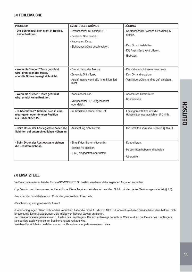
53
DEUT
SCH
6.0 FEHLERSUCHE
PROBLEM EVENTUELLE GRÜNDE LÖSUNG- Die Bühne setzt sich nicht in Betrieb. Keine Reaktion.
- Trennschalter in Position OFF
- Fehlende Stromzufuhr.- Kabelanschlüsse.- Sicherungsdrähte geschmolzen.
- Nottrennschalter wieder in Position ON drehen.
- Den Grund feststellen.- Die Anschlüsse kontrollieren.- Ersetzen.
- Wenn die “Heben” Taste gedrücktwird, dreht sich der Motor,aber die Bühne bewegt sich nicht.
- Drehrichtung des Motors.- Zu wenig Öl im Tank.- Auslaßmagnetventil (EV1) funktionniert nicht.
- Die Kabelanschlüsse umwechseln.- Den Ölstand ergänzen.- Ventil überprüfen, und es ggf. ersetzen.
- Wenn die “Heben” Taste gedrücktwird, erfolgt keine Reaktion.
- Kabelanschlüsse.
- Mikroschalter FC1 eingeschaltet oder defekt.
- Anschlüsse kontrollieren.- Kontrollieren.
- Hubschlitten P1 befindet sich in einerniedrigeren oder höheren Positionals Hubschlitten P2.
- Im Kreislauf befindet sich Luft. - Leitungen entlüften und die Hubschlitten neu ausrichten (§ 3.4.5).
- Beim Druck der Abstiegstaste halten dieSchlitten auf unterschiedlichen Höhen an.
- Ausrichtung nicht korrekt. - Die Schlitten korrekt ausrichten (§ 3.4.5).
- Beim Druck der Abstiegstaste steigendie Schlitten nicht ab.
- Eingriff des Sicherheitsventils.- Schlitte P2 blockiert- (FC2) eingegriffen oder defekt.
- Kontrollieren.
- Hubschlitten heben und befreien
- Überprüfen
7.0 ERSATZTEILE
Die Ersatzteile müssen bei der Firma AGM-COS.MET. Srl bestellt werden und die folgenden Angaben enthalten:
• Tip, Version und Kennummer der Hebebühne. Diese Angaben befinden sich auf dem Schild mit dem jedes Gerät ausgestattet ist (§ 1.5).
• Nummer der Ersatzteiltafel und Code des gewünschten Ersatzteils.
• Beschreibung und gewünschte Anzahl.
• Lieferbedingungen. Wenn nicht anders vereinbart, haftet die Firma AGM-COS.MET. Srl, obwohl sie diesen Service besonders betreut, nichtfür eventuelle Lieferverzögerungen, die infolge von höherer Gewalt entstehen.Die Transportspesen gehen immer zu Lasten des Empfängers. Die sich unterwegs befindliche Ware wird auf die Gefahr des Empfängerstransportiert, auch wenn sie frei Bestimmungsort verkauft wird.Beziehen Sie sich beim Bestellen nur auf die Bestellnummer jedes einzelnen Teiles.
54
INDICE
ANTES DE OPERAR CON EL ELEVADOR LEER ATENTAMENTE LAS INSTRUCCIONESDE ESTE MANUAL
1.0 PREÁMBULO.................................................................................................................................................................................................... 551.1 GARANTÍA........................................................................................................................................................................................................ 551.1.1 Exclusión de la garantía.................................................................................................................................................................................... 551.2 LA CERTIFICACIÓN CE .................................................................................................................................................................................. 551.3 EMPLEO............................................................................................................................................................................................................ 561.4 IDENTIFICACIÓN DEL ELEVADOR................................................................................................................................................................. 562.0 NORMAS GENERALES DE SEGURIDAD Y PREVENCIÓN DE ACCIDENTES............................................................................................. 562.1 NIVEL DE PELIGRO......................................................................................................................................................................................... 562.2 SEÑALES DE ADVERTENCIA.......................................................................................................................................................................... 572.3 VESTUARIO...................................................................................................................................................................................................... 572.4 ECOLOGÍA Y CONTAMINACIÓN ..................................................................................................................................................................... 572.4.1 Desmantelación del puente ............................................................................................................................................................................... 572.5 EMPLEO CON SEGURIDAD ............................................................................................................................................................................ 572.6 MANUTENCIÓN EN SEGURIDAD.................................................................................................................................................................... 583.0 MANIPULACIÓN E INSTALACIÓN................................................................................................................................................................... 593.1 TRANSPORTE Y DESCARGA.......................................................................................................................................................................... 593.2 INSTALACIÓN .................................................................................................................................................................................................. 593.3 CIMENTACIONES ............................................................................................................................................................................................ 593.4 COLOCACIÓN E INSTALACIÓN DE LA ESTRUCTURA ................................................................................................................................. 593.4.1 SITUACIÓN DE LAS COLUMNAS Y DEL TRANSVERSAL ............................................................................................................................. 593.4.2 CONEXIONES OLEODINÁMICAS ................................................................................................................................................................... 603.4.3 CONEXIONES DE LA RED ELÉCTRICA ......................................................................................................................................................... 603.4.4 RELLENADO DEL EQUIPO OLEODINÁMICO................................................................................................................................................. 613.4.5 ALINEACIÓN CARROS..................................................................................................................................................................................... 613.4.5.1 ALINEACIÓN CARROS EN LA PUESTA EN MARCHA ................................................................................................................................... 613.4.5.2 ALINEACIÓN CARROS EN FONCIONAMIENTO ............................................................................................................................................ 613.4.6 APLICACIÓN ETIQUETAS ADHESIVAS Y PICTOGRAMAS ........................................................................................................................... 624.0 IINSTRUCCIONES PARA EL MANEJO............................................................................................................................................................ 624.1 PANEL DE MANDOS......................................................................................................................................................................................... 624.1.1 Subida del elevador .......................................................................................................................................................................................... 624.1.2 Bajada del elevador .......................................................................................................................................................................................... 624.1.3 Pulsador de emergencia /off............................................................................................................................................................................. 634.1.4 Pulsador de restablecimiento /ON .................................................................................................................................................................... 634.1.5 Indicador luminosa de tensión .......................................................................................................................................................................... 634.2 EXCLUSIÓN DEL ESTACIONAMIENTO AUTOMÁTICO .............................................................................................................................. 634.3 PROCEDIMIENTO DE ELEVACIÓN................................................................................................................................................................. 644.4 PROCEDIMIENTO PARA LA BAJADA.............................................................................................................................................................. 644.5 DISPOSITIVOS DE SEGURIDAD..................................................................................................................................................................... 645.0 BAJADA DE EMERGENCIA ............................................................................................................................................................................. 655.1 MANUTENCIÓN................................................................................................................................................................................................ 655.1.1 COMPROBACIÓN DE LOS DISPOSITIVOS DE SEGURIDAD ....................................................................................................................... 655.1.2 Indicador luminoso de presencia tensión.......................................................................................................................................................... 655.1.3 Protecciones mecánicas de estacionamiento carros ....................................................................................................................................... 655.1.4 Protecciones contra la desalineación de los carros .......................................................................................................................................... 655.1.5 Tapones con espesor de goma......................................................................................................................................................................... 655.2 Pulsador de emergencia /OFF .......................................................................................................................................................................... 245.2.1 MANUTENCIÓN PERIÓDICA ........................................................................................................................................................................... 665.2.2 Cada semana .................................................................................................................................................................................................... 665.2.3 Cada mes .......................................................................................................................................................................................................... 665.3 Cada 200 horas de funcionamiento .................................................................................................................................................................. 666.0 BOMBA HIDRÁULICA DE EMERGENCIA ....................................................................................................................................................... 677.0 BUSQUEDA DE AVERIAS E INCONVENIENTES .......................................................................................................................................... 677.1 PARTES DE REPUESTO.................................................................................................................................................................................. 687.2 EQUIPO OLEODINAMICO ............................................................................................................................................................................... 697.3 DIAGRAMA CIRCUITO ELÉCTRICO DE POTENCIA ...................................................................................................................................... 707.4 DIAGRAMA CIRCUITO ELÉCTRICO DE POTENCIA ..................................................................................................................................... 717.5 DIAGRAMA CIRCUITO ELÉCTRICO DE POTENCIA ...................................................................................................................................... 727.6 DIAGRAMA CIRCUITO ELÉCTRICO DE MANDO .......................................................................................................................................... 73
PLANO SITUACIÓN COMPONENTS............................................................................................................................................................... 74Tav. I................................................................................................................................................................................................................... 76Tav. II.................................................................................................................................................................................................................. 78Tav. III ................................................................................................................................................................................................................ 80Tav. IV ............................................................................................................................................................................................................... 82Tav. V.................................................................................................................................................................................................................. 84 Tav. VI-VII........................................................................................................................................................................................................... 86RESERVADO PARA EL TÉCNICO INSTALADOR............................................................................................................................................
1.0 PREÁMBULO
En este manual se ilustran las instrucciones para la instalación, el empleo y la manutención del equipo de elevación denominado “ELEVA-DOR ELECTRO-HIDRÁULICO CON DOS COLUMNAS PARA VEHÍCULOS” serie “G 50”, producido por la empresa AGM-COS-MET srl de Almisano de Lonigo (VI) Italia. En la continuación de la descripción del elevador para vehículos con dos columnas se denominará simple-mente “elevador”. Las versiones del puente “G50” que se fabrican (Fig. 1), pueden ser identificadas en los tipos siguentes:
• G 50 - G 50 A (modelo base con una capacidad máxima de 5000 Kg.)• G 50 H - G 50 A H (modelo con prolongación de las columnas estándar con capacidad máxima de 5000 Kg.)• G 50 HL - G 50 A HL (modelo con prolongación de las columnas alto con capacidad máxima de 5000 Kg.)
El elevador en sus varias versiones, está compuesto por dos estructuras verticales simétricas, denominadas columnas, que se deben fijar bien al suelo. Ambas columnas están equipadas con unos carros de elevación con accionamiento electro-hidráulico.Los dos carros de elevación están acoplados hidráulicamente para poder mantener el mismo nivel durante la fase de trabajo.El funcionamiento de la máquina es el siguiente: el motor eléctrico acciona una bomba hidráulica con engranajes, que manda aceite a unos martinetes hidráulicos, situados en la parte superior de las columnas, que elevan los dos carros.Las versiones marcadas en la parte final de la sigla con las letras “H” y “HL” se diferencian de las demás por la altura superior de sus colum-nas. Ademas, el puente tipo “G 50 A” se diferencia del tipo “G50” solamente para la distancia mas grande entre l’interno de las columnas.Dichas versiones están equipadas con unos elementos de prolongación que se encuentran en la parte superior de las columnas que aumen-tan la altura del suelo del transversal superior de conexión del elevador.Del cumplimiento de las instrucciones que se describen en este manual dependen su funcionamiento regular, la economía y la duración de los elevadores. En la última parte del manual se indican las partes de repuesto que se pueden abastecer.Es obligatorio atenerse a todo lo que se describe en este manual; la Empresa constructora declina toda responsabilidad debida a la negligencia y al incumplimiento de dichas instrucciones y al uso impropio o irrazonable del elevador.El incumplimiento de las instrucciones del presente manual anula automáticamente la garantía.
1.1 GARANTÍA
La AGM-COS. MET garantiza el elevador y sus accesorios por un periodo de 24 meses de la fecha de compra.Dicha garantía cubre la reparación o sustitución gratuita de aquellas partes que después del examen atento del Servicio de Asistencia Técnica del Constructor, resulten con defectos de fabricación en su origen, a exclusión de todas las partes eléctricas. La garantía se limita sólo a los defectos de los materiales y cesa en el momento en que las partes devueltas hayan sido adulteradas o de todos modos desmontadas por personal no autorizado a tal fin. Están excluidas de la garantía las responsabilidades por daños directos o indirectos de personas, animales o cosas por causa de la avería o del malfuncionamiento de la máquina. Los gastos relativos a la sustitución de lubricantes, gastos de transporte y eventuales tributos de aduana, el IVA y demás que no se haya escrito en el contrato de abastecimiento son a cargo del comprador. La sus-titución o reparación de los materiales en garantía no prorrogan en todo caso los términos de la garantía misma. El comprador puede exigir sus derechos sobre la garantía sólo si habrá respetado las condiciones que conciernen la prestación de la garantía, eventualmente anexa al contrato de abastecimiento. En el momento en que las partes no entiendan poner a juicio arbitral las controversias derivadas del contrato de abastecimiento o en el caso en que se requiera el fallo de un órgano del Foro ordinario, se considerará territorialmente competente sólo el Foro de Vicenza.
1.1.1. EXCLUSIÓN DE LA GARANTÍA
A la entrega hay que comprobar que el producto no hay sufrido daños durante su transporte y que el equipamiento de accesorios esté inte-gro y completo. Eventuales reclamaciones se tendrán que presentar en el plazo de 8 días de la entrega del elevador. Además de los casos previstos en el contrato de abastecimiento la garantía decae:• cuando se verifique un error del operador en el manejo• cuando el daño sea causado por la falta de mantenimiento• cuando se sobrepase su capacidad efectiva prevista• cuando la máquina haya sufrido modificaciones y el daño haya sido causado por dichas modificaciones, después de posibles intervenciones de reparación efectuadas por el usuario sin la autorización de la AGM-COS.MET o por causa del empleo de piezas de repuesto no originales.
1.2 LA CERTIFICACIÓN CE
La directiva 98/37/CE conocida comúnmente como “Directiva Máquinas”, precisa las condiciones con las que una máquina se puede introducir en el mercado. Dicha Directiva prescribe que todas las máquinas pueden ser comercializadas o puestas en servicio sólo si no perjudican la seguridad y la salud de las personas, animales domésticos o de los bienes. Para certificar la conformidad del elevador de las disposiciones de la Directiva la AGM-COS.MET, antes de su comercialización, ha sometido un ejemplar de la máquina al examen de un organismo notificado. El elevador ha sido construido en conformidad con las disposiciones que contiene la directiva 98/37/CE ha superado el examen efectuado y por lo tanto, se puede introducir en el mercado sin perjudicar la seguridad del usuario. El elevador se entrega al cliente equipado y acompañado de:
• Declaración CE de conformidad• Marca CE• Manual de instrucciones de manejo
55
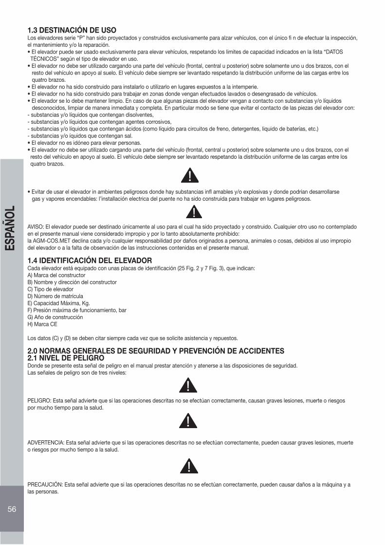
1.3 DESTINACIÓN DE USOLos elevadores serie “P” han sido proyectados y construidos exclusivamente para alzar vehículos, con el único fi n de efectuar la inspección, el mantenimiento y/o la reparación.• El elevador puede ser usado exclusivamente para elevar vehículos, respetando los limites de capacidad indicados en la lista “DATOS TÉCNICOS” según el tipo de elevador en uso.• El elevador no debe ser utilizado cargando una parte del vehículo (frontal, central u posterior) sobre solamente uno u dos brazos, con el resto del vehículo en apoyo al suelo. El vehículo debe siempre ser levantado respetando la distribución uniforme de las cargas entre los quatro brazos.• El elevador no ha sido construido para instalarlo o utilizarlo en lugares expuestos a la intemperie.• El elevador no ha sido construido para trabajar en zonas donde vengan efectuados lavados o desengrasado de vehículos.• El elevador se lo debe mantener limpio. En caso de que algunas piezas del elevador vengan a contacto con substancias y/o líquidos desconocidos, limpiar de manera inmediata y completa. En particular modo se tiene que evitar el contacto de las piezas del elevador con:- substancias y/o líquidos que contengan disolventes,- substancias y/o líquidos que contengan agentes corrosivos,- substancias y/o líquidos que contengan ácidos (como líquido para circuitos de freno, detergentes, liquido de baterías, etc.)- substancias y/o íquidos que contengan sal.• El elevador no es idóneo para elevar personas.• El elevador no debe ser utilizado cargando una parte del vehículo (frontal, central u posterior) sobre solamente uno u dos brazos, con el resto del vehículo en apoyo al suelo. El vehículo debe siempre ser levantado respetando la distribución uniforme de las cargas entre los quatro brazos.
• Evitar de usar el elevador in ambientes peligrosos donde hay substancias infl amables y/o explosivas y donde podrian desarrollarse gas y vapores encendables: l’installación electrica del puente no ha sido construida para trabajar en lugares peligrosos.
AVISO: El elevador puede ser destinado únicamente al uso para el cual ha sido proyectado y construido. Cualquier otro uso no contempladoen el presente manual viene considerado impropio y por lo tanto absolutamente prohibido:la AGM-COS.MET declina cada y/o cualquier responsabilidad por daños originados a persona, animales o cosas, debidos al uso impropiodel elevador o a la falta de observación de las instrucciones contenidas en el presente manual.
1.4 IDENTIFICACIÓN DEL ELEVADORCada elevador está equipado con unas placas de identificación (25 Fig. 2 y 7 Fig. 3), que indican:A) Marca del constructorB) Nombre y dirección del constructorC) Tipo de elevadorD) Número de matrículaE) Capacidad Máxima, Kg.F) Presión máxima de funcionamiento, barG) Año de construcciónH) Marca CE
Los datos (C) y (D) se deben citar siempre cada vez que se solicite asistencia y repuestos.
2.0 NORMAS GENERALES DE SEGURIDAD Y PREVENCIÓN DE ACCIDENTES2.1 NIVEL DE PELIGRODonde se presente esta señal de peligro en el manual prestar atención y atenerse a las disposiciones de seguridad.Las señales de peligro son de tres niveles:
PELIGRO: Esta señal advierte que si las operaciones descritas no se efectúan correctamente, causan graves lesiones, muerte o riesgospor mucho tiempo para la salud.
ADVERTENCIA: Esta señal advierte que si las operaciones descritas no se efectúan correctamente, pueden causar graves lesiones, muerteo riesgos por mucho tiempo a la salud.
PRECAUCIÓN: Esta señal advierte que si las operaciones descritas no se efectúan correctamente, pueden causar daños a la máquina y alas personas.
56
ESPA
ÑOL
ADVERTENCIA: Leer atentamente las siguientes normas, quién no aplicase cuanto se describe puede sufrir daños irreparables o provocarlosa personas, animales o cosas.La Empresa A.G.M:-COS.MET S.r.l. declina además toda responsabilidad por daños causados del empleo inadecuado del elevador o acausa de modificaciones efectuadas sin autorización del constructor.
2.2. SEÑALES DE ADVERTENCIALas señales de seguridad (Fig. 4) descritas en este manual, están indicadas en el elevador y señalan situaciones de inseguridad y de peligro.Las etiquetas se tienen que mantener limpias y se deben sustituir inmediatamente si se despegasen o estuvieran dañadas.Leer atentamente el significado de las señales de seguridad y memorizarlo bien:1) Es obligatorio leer atentamente el manual de instrucciones antes de empezar cualquier operación con el elevador. Es obligatorio antes de efectuar cualquier operación de manutención desconectar la alimentación y leer atentamente el manual de instrucciones.2) Peligro de caída: no subirse al elevador.3) Peligro de aplastamiento: no acercarse a las partes en movimiento4) Peligro de electrocución: cuadro bajo tensión antes de efectuar cualquier intervención hay que desconectar siempre la alimentación eléctrica.
2.3 LUGAR DE INSTALACIÓN Y VESTUARIOEligir un lugar idóneo para instalar la máquina, en un ambiente de trabajo seguro, evaluando cuidadosamente los aspectos siguientes:• El lugar debe ser seguro, libre de obstáculos y protegido contra los agentes atmosféricos. Del panel de mando el operador debe poder supervisar la instalación completa y el área de operación y ver inmediatamente la presencia de gente desautorizada o de obstáculos que pueden causar peligro• La distancia mínima de las columnas y de la zona peligrosa (Fig.4) de las paredes del edificio donde se instala el elevador, debe ser de por lo meno 70 cm.• La iluminación del área debe ser buena, pero sin deslumbramientos y sin luces demasiado brillantes. El lugar de instalación debe estar libre de fuentes o de procesos de trabajo que pueden desarrollar gases o vapores inflamables.• Evitar ponerse ropas no idóneas. Se podrían enganchar en las partes en movimiento del elevador.• Según las indicaciones de las normas en el país de instalación del elevador, el operador tendrá que usar, aparte de la ropa idóneas, los accesorios adicionales de protección del accidente como, por ejemplo: casco, gafas, guantes, zapatos especiales, etc.
2.4 ECOLOGÍA Y CONTAMINACIÓN• El elevador no se debe emplear para el lavado, el desengrasado, pulido y para operaciones de lijado de los automóviles.• Respetar las leyes en vigor del país dónde se haya efectuado la instalación del elevador, relativos a su manejo y a la desmantelación de losproductos que se empleen para la limpieza y la manutención del elevador; cumpliendo cuanto aconseja el constructor de dichos productos.
2.4.1 DEMOLIÇÃO DA PLATAFORMAA fi m de evitar danos ao ambiente, algumas precauções devem ser tomadas quando a plataforma tiver que ser demolida ou não vai mais ser usada:• o óleo hidráulico da central oleodinâmica, do seu circuito e dos cilindros, deve ser recolhido. (AS PONTES ELETROMECÂNICAS SÃO EXCLUÍDAS)• desmontar as várias partes da plataforma dividindo-as em grupos de material homogêneo para fazer a coleta diferenciada.• o óleo hidráulico usado, as partes de borracha e de ferro são resíduos industriais especiais. Fazer a sua eliminação ou estocagem pr visória de acordo com as leis antipoluição em vigor no país onde se utiliza a plataforma. (AS PONTES ELETROMECÂNICAS SÃO EXCLUÍDAS)
2.5 EMPLEO CON SEGURIDAD• Está prohibido accionar o que accionen el elevador personas que no hayan leído completamente, comprendido y asimilado perfectamente todo lo que se ilustra en este manual.• Está prohibido que accionen ele elevador personal que no haya sido correctamente preparado, competente o que no posea buenas condiciones de salud.• Está prohibido tocar o apoyarse en las partes en movimiento del elevador o interponerse entre las partes durante las maniobras de subida y de bajada del elevador.• Está prohibido subir personas, animales o cosas: el elevador ha sido construido exclusivamente para la elevación de automóviles.• Está prohibido elevar el automóvil en el elevador con personas, animales u objetos a bordo.• Está prohibida la detención, el paso de personas o animales debajo el autovehículo levantado y alrededor del puente, cuando se lo maniobra también en pequeños desplazamientos, cuando el interruptor/Seccionador de emergencia (19 Fig. 2) esté en pos. ON (eventualmente girarlo) y cuando las seguras mecánicas no han sido insertadas.• Está prohibido depositar objetos en los brazos del elevador particularmente aquellos objetos que si cayeran pudieran causar daños a personas o cosas.• Está prohibido sobrecargar el elevador: el empleo del elevador está consentido sólo y exclusivamente para la elevación de la capacidad indicada en la tabela DATOS TECNICOS.• Es obligatorio colocar los vehículos en el elevador de modo que el peso esté bien repartido y centrado; las puertas tienen que permanecer cerradas; no pueden sobresalir objetos fuera de la sagoma del automóvil; el baricentro del vehículo tiene que caer al interior de los 4 apoyos; desmontando algunas partes del vehículo se puede desplazar su baricento.
57
ESPA
ÑOL
• No sobrecargar el elevador. El unico uso consentido del elevador es el de cargar la capacidad indicada en la tabla “DISTRIBUCIÓN CARGAS” (Fig. 5), posicionando el vehiculo sobre el puente de manera que sean respectadas las siguentes indicaciónes previstas en la norma europea EN 1493:1998:1. El peso del vehiculo por elevar, representado para la suma de las dos cargas Q1 y Q2 (ver los simbolos en Fig. 5), no debe sobrepasar la capacidad maxima del puente (Qmax); o sea (Q1+Q2) ≤ Qmax2. La carga maxima Q1 (Q1max) puesta indiferentemente sobre los brazos cortos o los brazos largos, no debe sobrepasar 3330 Kg como indicado en la Fig. 5, o sea (Q1max ≤ 3330 Kg).
AGM-COS.MET declina cada y/o cualquier responsabilidad por daños originados a persona, animales o cosas, debidos al uso impropio del elevador o a la falta de observación de las instrucciones contenidas en el presente manual.
• Es obligatorio instalar el elevador en un terreno nivelado, liso y horizontal.• Es obligatorio instalar el elevador cerca de una toma de corriente y conectar el mismo a un enchufe conforme a las normativas en vigor
del País donde se instale el elevador.• Es obligatorio instalar el elevador en un lugar protegido del agua, hielo y viento.• Es obligatorio antes de poner en funcionamiento el elevador controlar la perfecta integridad de todas sus protecciones y del elevador.• Die “HEBEN” Taste (22 Abb. 2) solange gedrückt halten, bis der Hubschlitten P1 die Maximalhöhe erreicht hat. Dann weitere 3 Liter Öl in den Tank füllen.• Es obligatorio que el vehículo que se debe elevar, sea conducido o manejado sólamente por personal idóneo a la conducción como prevean las leyes en
vigor del país donde se emplee el elevador.• Es obligatorio comprobar, antes de poner en funcionamiento del elevador que al interior del área de peligro (Fig. 5) o en cercanía no se encuentren
personas extrañas a ésta o animales.• Se aconseja antes de empezar el trabajo de familiarizarse con los dispositivos de mando y de su función.• Se aconseja prestar atención durante la maniobra de subida del elevador, ya que los vehículos son de diferentes tamaños, a no aplastar el vehículo contra
el techo del taller.• Es obligatorio alzar unos 10 cm de altura el vehículo y comprobar su estabilidad antes de efectuar la operación de subida total.• Se aconseja antes de efectuar la maniobra de bajada del elevador de comprobar que por debajo y alrededor del vehículo elevado no se encuentren
objetos; eventualmente quitarlos.• Es obligatorio antes de dejar el puesto de trabajo, bajar el puente y girar el interruptor/Seccionador de emergencia (23 Fig.2) en pos. OFF..• Está prohibido en cualquier caso modificar la centralita hidráulica (17 Fig. 3).• Es obligatorio que en la zona superior del elevador no se encuentren aparatos conectados a la red eléctrica En caso de colisión de dichos aparatos con
el elevador o con el vehículo se podrían verificar descargas eléctricas peligrosas para las personas.• Es obligatorio en caso de peligro para las personas, los animales o cosas, girar tempestivamente el interruptor/Seccionador de emergencia
(23 Fig.2) que sea en pos. OFF.• Se aconseja en caso de contacto de la piel con el aceite del equipo hidráulico, lavarse abundantemente con agua y jabón.• Es obligatorio alzar el elevador, para poder acceder al vehículo por debajo, con un espacio mínimo que permita estar de pie.• Es obligatorio efectuar la alineación de los carros antes de empezar a operar con el elevador y durante su manejo, después de algunos ciclos de subida
- bajada.• Está prohibido operar con el elevador cuando después de efectuar la alineación de los carros , los brazos porta carga permaneces desalineados; se puede
verificar la caída del vehículo.• Es obligatorio en caso de malfuncionamiento del elevador interrumpir las operaciones e interpelar siempre al constructor o al taller autorizado• Está prohibido operar con el elevador cuando se noten anomalías o malfuncionamiento durante su empleo.
Para limpiar el elevador, usar solamente un paño mórbido. Se permite mojar ligeramente el paño con alcool para limpiar los puntos ensuciados con aceite o grasa. No utilice otros solventes para no dañar los componentes plásticos y las piezas pintadas.
2.6 MANUTENCIÓN EN SEGURIDAD
• Es obligatorio comprobar periódicamente la integridad de los dispositivos de protección de la estructura.• Es obligatorio comprobar periódicamente el cierre y la hermeticidad de los tornillos, tuercas y empalmes.• Es obligatorio controlar periódicamente que los órganos móviles de elevación (rodillos, pomos, etc.) se encuentren en buen estado y bien
engrasados.• Se aconseja respetar la conformidad de los aceites aconsejados.
• Es obligatorio que las partes de recambio correspondan a las características definidas por el constructor. Emplear sólamente repuestos originales.• Es obligatorio que las operaciones de desplazamiento y de elevación del elevador o de sus partes se efectúen con modalidades, cables de acero, cuerdas,
cadenas y accesorios para la elevación idóneos y conformes a las normativas en vigor del país donde se efectúen dichasoperaciones.
• Es obligatorio que la instalación se efectúe de manera que el elevador o el vehículo elevado no puedan aplastar, desenganchar o rozar otros objetos, particularmente los equipos eléctricos, del agua y del gas.
• Está prohibido quitar o modificar los dispositivos de seguridad.
• Es obligatorio que la instalación y la manutención del elevador sea efectuada sólamente por personal calificado y que sigan las indicaciones ilustradas en este manual.
• Es obligatorio desconectar la alimentación eléctrica cada vez que se tenga que efectuar reparaciones o manutenciones.• Es obligatorio seguir escrupulosamente la manutención como se indica en este manual y que sustituyan las personas encargadas las partes
dañadas o desgastadas• Está prohibido efectuar intervenciones o regulaciones en los equipamientos sino se ha desconectado la alimentación eléctrica.• Es obligatorio limpiar cuando esten sucias y sustituir inmediatamente cuando se hayan despegado o dañado las etiquetas con las instrucciones
que tiene el elevador que dan los consejos necesarios para evitar accidentes.• Se aconseja de eliminar completamente las manchas de aceite del suelo nada más se produzcan ya que pueden ser muy peligrosas.
58
ESPA
ÑOL
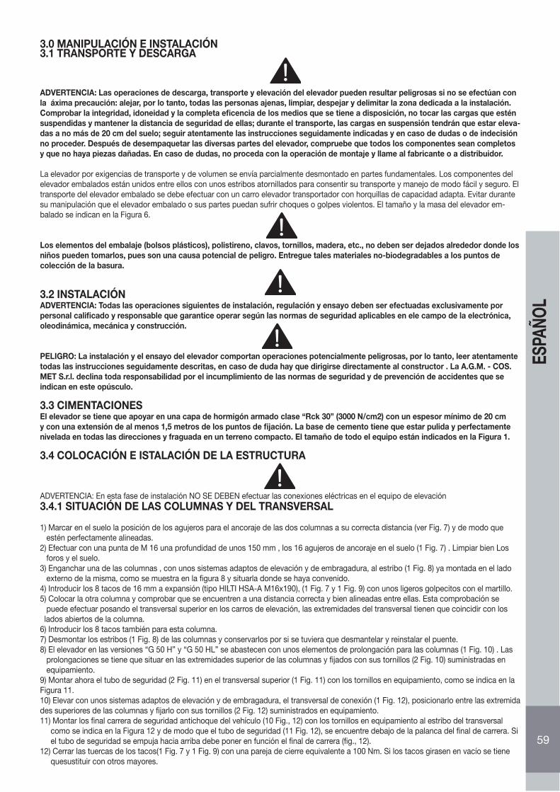
3.0 MANIPULACIÓN E INSTALACIÓN3.1 TRANSPORTE Y DESCARGA
ADVERTENCIA: Las operaciones de descarga, transporte y elevación del elevador pueden resultar peligrosas si no se efectúan con la áxima precaución: alejar, por lo tanto, todas las personas ajenas, limpiar, despejar y delimitar la zona dedicada a la instalación. Comprobar la integridad, idoneidad y la completa eficencia de los medios que se tiene a disposición, no tocar las cargas que estén suspendidas y mantener la distancia de seguridad de ellas; durante el transporte, las cargas en suspensión tendrán que estar eleva-das a no más de 20 cm del suelo; seguir atentamente las instrucciones seguidamente indicadas y en caso de dudas o de indecisión no proceder. Después de desempaquetar las diversas partes del elevador, compruebe que todos los componentes sean completos y que no haya piezas dañadas. En caso de dudas, no proceda con la operación de montaje y llame al fabricante o a distribuidor.
La elevador por exigencias de transporte y de volumen se envía parcialmente desmontado en partes fundamentales. Los componentes del elevador embalados están unidos entre ellos con unos estribos atornillados para consentir su transporte y manejo de modo fácil y seguro. El transporte del elevador embalado se debe efectuar con un carro elevador transportador con horquillas de capacidad adapta. Evitar durante su manipulación que el elevador embalado o sus partes puedan sufrir choques o golpes violentos. El tamaño y la masa del elevador em-balado se indican en la Figura 6.
Los elementos del embalaje (bolsos plásticos), polistireno, clavos, tornillos, madera, etc., no deben ser dejados alrededor donde losniños pueden tomarlos, pues son una causa potencial de peligro. Entregue tales materiales no-biodegradables a los puntos decolección de la basura.
3.2 INSTALACIÓNADVERTENCIA: Todas las operaciones siguientes de instalación, regulación y ensayo deben ser efectuadas exclusivamente por personal calificado y responsable que garantice operar según las normas de seguridad aplicables en ele campo de la electrónica, oleodinámica, mecánica y construcción.
PELIGRO: La instalación y el ensayo del elevador comportan operaciones potencialmente peligrosas, por lo tanto, leer atentamente todas las instrucciones seguidamente descritas, en caso de duda hay que dirigirse directamente al constructor . La A.G.M. - COS.MET S.r.l. declina toda responsabilidad por el incumplimiento de las normas de seguridad y de prevención de accidentes que se indican en este opúsculo.
3.3 CIMENTACIONESEl elevador se tiene que apoyar en una capa de hormigón armado clase “Rck 30” (3000 N/cm2) con un espesor mínimo de 20 cm y con una extensión de al menos 1,5 metros de los puntos de fijación. La base de cemento tiene que estar pulida y perfectamente nivelada en todas las direcciones y fraguada en un terreno compacto. El tamaño de todo el equipo están indicados en la Figura 1.
3.4 COLOCACIÓN E ISTALACIÓN DE LA ESTRUCTURA
ADVERTENCIA: En esta fase de instalación NO SE DEBEN efectuar las conexiones eléctricas en el equipo de elevación3.4.1 SITUACIÓN DE LAS COLUMNAS Y DEL TRANSVERSAL
1) Marcar en el suelo la posición de los agujeros para el ancoraje de las dos columnas a su correcta distancia (ver Fig. 7) y de modo que estén perfectamente alineadas.2) Efectuar con una punta de M 16 una profundidad de unos 150 mm , los 16 agujeros de ancoraje en el suelo (1 Fig. 7) . Limpiar bien Los foros y el suelo.3) Enganchar una de las columnas , con unos sistemas adaptos de elevación y de embragadura, al estribo (1 Fig. 8) ya montada en el lado externo de la misma, como se muestra en la figura 8 y situarla donde se haya convenido.4) Introducir los 8 tacos de 16 mm a expansión (tipo HILTI HSA-A M16x190), (1 Fig. 7 y 1 Fig. 9) con unos ligeros golpecitos con el martillo.5) Colocar la otra columna y comprobar que se encuentren a una distancia correcta y bien alineadas entre ellas. Esta comprobación se puede efectuar posando el transversal superior en los carros de elevación, las extremidades del transversal tienen que coincidir con los lados abiertos de la columna.6) Introducir los 8 tacos también para esta columna.7) Desmontar los estribos (1 Fig. 8) de las columnas y conservarlos por si se tuviera que desmantelar y reinstalar el puente.8) El elevador en las versiones “G 50 H” y “G 50 HL” se abastecen con unos elementos de prolongación para las columnas (1 Fig. 10) . Las prolongaciones se tiene que situar en las extremidades superior de las columnas y fijados con sus tornillos (2 Fig. 10) suministradas en equipamiento.9) Montar ahora el tubo de seguridad (2 Fig. 11) en el transversal superior (1 Fig. 11) con los tornillos en equipamiento, como se indica en laFigura 11.10) Elevar con unos sistemas adaptos de elevación y de embragadura, el transversal de conexión (1 Fig. 12), posicionarlo entre las extremidades superiores de las columnas y fijarlo con sus tornillos (2 Fig. 12) suministrados en equipamiento.11) Montar los final carrera de seguridad antichoque del vehículo (10 Fig., 12) con los tornillos en equipamiento al estribo del transversal como se indica en la Figura 12 y de modo que el tubo de seguridad (11 Fig. 12), se encuentre debajo de la palanca del final de carrera. Si el tubo de seguridad se empuja hacia arriba debe poner en función el final de carrera (fig., 12).12) Cerrar las tuercas de los tacos(1 Fig. 7 y 1 Fig. 9) con una pareja de cierre equivalente a 100 Nm. Si los tacos girasen en vacío se tiene quesustituir con otros mayores.
59
ESPA
ÑOL
3.4.2 CONEXIONES OLEODINÁMICAS
PRECAUCIÓN: En esta fase de la instalación NO SE DEBEN efectuar las conexiones eléctricas en el equipo de elevación.
PRECAUCIÓN: Es muy importante seguir correctamente las indicaciones que conciernen a las conexiones del equipo.
• Conectar el tubo en hierro (3 Fig. 12), que se encuentra al interior del transversal de conexión (1 Fig. 12) con sus respectivos elementos de empalme de los tubos que se encuentran al interior de las dos columnas (3A Fig. 12). En las versiones “G 50 H” y “G 50 HL” conectar los tubos de la columna con los del transversal.• Extraer de la columna P2 el tubo de descarga de goma (4 Fig. 12) en equipamiento y llevarlo hasta la centralita hidráulica y conectarlo a su relativo elemento de empalme (7 Fig. 12).• Para finalizar comprobar que todos los elementos de empalme estén bien cerrados.• Atar el tubo (3 Fig. 12) en el centro del transversal de conexión con los tornos suministrados en equipamiento (15 Fig. 12).
3.4.3 CONEXIONES DE LA RED ELÉCTRICA
PRECAUCIÓN:• La tensión eléctrica de conexión al cuadro del elevador tiene que corresponder con la tensión que se encuentre indicada en el cuadro eléctrico.• El cuadro eléctrico tiene que estar conectado a un interruptor general construido y instalado según las normativas vigentes del País donde se emplee.• El equipo eroga la energía eléctrica al cuadro eléctrico del elevador, se debe efectuar según las normativas del País donde se emplee.• La capacidad mínima necesaria es de 3 kW.• La sección mínima de los hilos eléctricos del circuito de potencia tienen que ser de 4 mm2• En esta fase el motor eléctrico se puede accionar sólo por unos instantes, para evitar posibles daños a la bomba hidráulica.
PROCEDIMIENTO:• Conectar el cable del microinterruptor montado en el transversal de conexión (5 Fig., 12) con la conexión numerada (6 Fig. 12) de la columna P1.• Conectar el cable del electroimán de la columna P2 con su conexión numerada de la columna P1.• Conectar el cable de alimentación eléctrica (14 Fig. 12) que sale de la columna P1 a la red de alimentación. La conexión se debe efectuar en respeto de las normativas del País donde se efectúe la instalación.
AVISO: Antes de efectuar las operaciónes a continuación descritas hay que leer atentamente las instrucciones en el capitulo 4.0 que describen las fonciones del panel de mando y gane un buen conocimiento de la función de la máquina realizando las diversasoperaciones con el elevador descargado.
• Poner en tensión la línea y controlar que el interruptor/Seccionador de emergencia (19 Fig.2) esté en posición ON (eventualmente girarlo).
• Presionar y soltar el pulsador “SUBIDA” (22 Fig. 2) y comprobar que el sentido de rotación del motor sea el mismo que el de la flecha (8 Fig. 12) imprimida en la campana de empalme de la base de motor (en sentido horario mirando desde el cárter superior del motor). En caso contrario, desconectar la corriente de la red e invertir dos fases en el panel de bornes de la caja de desviación).
60
ESPA
ÑOL
3.4.4 RELLENADO DEL EQUIPO OLEODINÁMICO
ADVERTENCIA: Comprobar constantemente que no se verifiquen perdidas de aceite, eventualmente desconectar la corriente eléc-trica y cerrar los empalmes que se hayan aflojado.
Proceder a la elevación de los carros en la siguiente manera:1) Desenroscar el tapón para la introducción del aceite (9 Fig. 12) y echar en el depósito (10 Fig. 12) 7 litros de aceite hidráulico ESSO NUTO H 32 o equivalente (viscosidad ISO VG 32).2) Presionar el pulsador de “SUBIDA” (22 Fig. 2) y mantenerlo presionado hasta que el carro P1 alcance una altura de unos 50 cm.3) Colocar los brazos (6 Fig. 2) cerca de los carros (4 Fig., 2) de modo que los brazos (6 Fig. 2) se monten con las protecciones salva pies (14 Fig. 2) dirigidas hacia la parte exterior del elevador.4) Montar los dos brazos respectivos al carro elevador por medio de la espina (2 Fig. 14) bloqueándola con los dos anillos elásticos (3 Fig. 14) a las extremidades. Prestar atención durante el montado de colocarlos correctamente con las protecciones antirotación de los brazos (5 Fig. 14): estas tienen que tener el sector dentado hacia la cremallera (4 Fig. 14) de cada brazo. Tirando hacia arriba el pomelo (5 Fig. 14) , se pueden excluir temporáneamente las protecciones antirotación de los brazos.5) Presionar el pulsador “SUBIDA” (22 Fig. 27bis) y mantenerlo presionado hasta que el carro P1 no llegue a su altura máxima. A este punto echar otros 3 litros más de aceite en el depósito.6) Presionar de nuevo el pulsador “SUBIDA” hasta que el carro P2 no alcance una altura de unos 50 cm.7) Montar los brazos al carro de la columna P2, repitiendo las operaciones indicadas en el punto 4).8) Presionar otra vez el pulsador “SUBIDA” (22 Fig. 2) hasta que el carro P2 alcance su altura máxima. Alcanzada su altura máxima, mantener todavía presionado los pulsadores por unos 10 o 15 segundos para permitir el mondado del aire.
3.4.5 ALINEACIÓN CARROS3.4.5.1 ALINEACIÓN DE LA PUESTA EN SERVICIO
1) Presionar el pulsador de BAJADA (23 Fig. 2), hasta alcanzar la altura mínima.2) Presionar el pulsador “SUBIDA” (22 Fig. 2) hasta que los dos carros alcancen la altura máxima.3) Después de unos 5 ÷ 10 minutos de parada, para poder permitir la separación de aire, eventualmente, presente en el aceite, hay que efectuar todavía un ciclo de SUBIDA - BAJADA como se indica en los puntos 1) y 2), comprobando el funcionamiento de los dispositivos de seguridad como se describe en este opúsculo.4) Con los carros completamente bajados, comprobar y si hiciera falta restablecer el nivel de aceite hasta alcanzar el nivel justo, que es de 2 o 3 cm debajo del agujero de introducción del aceite.
ADVERTENCIA: es obligatorio después de haber instalado el elevador o después de haber efectuado las operaciones de manuten-ción en el sistema idraulico, antes de efectuar la elevación de un vehículo, comprobar el funcionamiento del dispositivo de seguri-dad contra la desalineación de los carros como se describe en el punto 5.1.3
La operación de alineación de los carros debe ser efectuada exclusivamente por personal calificado y responsable, ya que es fun-damentalmente importante para el buen funcionamiento del elevador y para la seguridad del operador.
3.4.5.2 ALINEACIÓN EN EJERCICIODurante el uso normal, la alienación de los carros se realiza automaticamente por el sistema oleodinámico de los cylindros en série con elcicuito de trasiego. No por esto es menos obligatorio efectuar la alienación cada vez que se observa una diferencia de nivel entre los dos carros. Presionarel pulsador “SUBIDA” (22 Fig. 2) hasta que los dos carros alcanzen la altura maxima. Tener presionado el pulsador por algunos segundos. (Es posible efectuar esta operación con el vehículo cargado sobre el elevador, à condición que la desalineación de los dos carros sea de maximo 3÷4 cm). Entonces continuar con la operación de bajada.
CUIDADO: Durante esta fase, averiguar que la desalineación de los carros quede la misma.
PELIGRO: Está prohibido operar con el elevador si, después de haber efectuado una operación de alineación de los carros, los brazos porta carga se desalinean rapidamente.
61
ESPA
ÑOL
3.4.6 APLICACIÓN ETIQUETAS ADHESIVAS Y PICTOGRAMASHay que aplicar al elevador las placas anexas al manual, siguiendo la disposición del esquema de la figura 3.
ADVERTENCIA: La falta de aplicación de las etiquetas es una causa que hace decaer las condiciones de garantía y la exclusión de responsabilidad del constructor por cualquier daño que derive del empleo del elevador.En caso de daño, deterioro con la consecuente ilegibilidad o perdida de una o de más etiquetas del elevador, hay que solicitarlas al vendedor detallando el número de su posición indicado en la figura 3 . Apenas posible aplicar las nuevas etiquetas en su posición exacta en el elevador.
4.0 INSTRUCCIONES PARA EL MANEJO
ADVERTENCIA: Leer las indicaciones ilustradas en el capítulo “Normas de seguridad y prevención de infortunios”.
ADVERTENCIA: Antes de efectuar cualquier operación de en la llave de contacto hay que cerciorarse de que ninguna persona se encuentre en cercanía del elevador.
4.1 PANEL DE MANDOSSeguidamente de indican las operaciones que se pueden ejecutar desde el panel de mandos:
4.1.1 SUBIDA DEL ELEVADOR• Controlar que el interruptor/Seccionador de emergencia (19 Fig. 2) esté en posición levantada (eventualmente girarlo).• Presionar el pulsante SUBIDA 21 Fig. 3) hasta el logro de la altura deseada.
• Al soltar el pulsante de subida, el elevador efectúa la fase de ESTACIONAMIENTO AUTOMÁTICO de los carritos, permitiendo así a los mismos de bajar y a los seguros mecánicos de inserirse.
IMPORTANTE: La función de ESTACIONAMIENTO AUTOMATICO, soltando el pulsador de SUBIDA (21 Fig. 3), es predispuesta para no actuar y quedar excluida, hasta que el perfil inferior del carro (Fig. 15), no alcanze una altura de mas de 20 cm del suelo. Este paragarantizar el paro immediato de los carros durante la fase inicial de levantamiento.
AVISO: Antes de efectuar la maniobra de subida, leer atentamente y asimilar las indicaciones del capitulo 4.2 PROCESO DE EL-EVACIÓN.
4.1.2 BAJADA DEL ELEVADOR
• Presionar el pulsador de BAJADA (23 Fig. 2) hasta alcanzar la altura deseada.
• Presionando el pulsador de BAJADA (23 Fig. 2), los carros suben un poco para permitir el desbloqueo de los seguros mecánicos, para ba-jarse después hasta que el pulsador esta presionado. Después de soltar el pulsador de subida, se activa la alarma acustica para indicar que el elevador esta acabando la fase de ESTACIONAMIENTO AUTOMATICO que permite a los carros de bajar hasta que los seguros mecànicos no se hajan accionado. La conclusion de la alarma acustica indica el completamiento de la fase de estacionamiento.
IMPORTANTE: La función de ESTACIONAMIENTO AUTOMATICO, soltando el pulsador de BAJADA (23 Fig. 2), es predispuesta para no actuar y quedar excluida, hasta que el perfil inferior del carro (Fig. 14), no alcanze una altura de mas de 20 cm del suelo. Este para garantizar el paro immediato de los carros durante la fase inicial de levantamiento.
62
ESPA
ÑOL
4.1.3 INTERRUPTOR /SECCIONADOR DE EMERGENCIA/OFF• Girando el Interruptor/Seccionador de emergencia (18 Fig. 2) hacia la pos.0 (OFF), el elevador deja de funcionar completamente.• Esta operación se efectúa siempre antes de acceder a la zona de trabajo debajo del elevador.• Llevando el Interruptor/Seccionador de emergencia a la posición I (ON), se autorizan las funciones del puente.En caso de defectos ó de roturas de uno ó más componentes ó en caso de anomalía o avería del circuito de alimentación no se producensituaciones de riesgo porque el ELEVADOR está provisto de dispositivo de seccionamiento de la línea eléctrica que permite aislar la máquina.Los controles de ascenso y descenso, además, son del tipo “ hombre muerto” (con accionamiento mantenido) por lo cual, en caso de averíadel circuito de alimentación no son posibles el encendido intempestivo, ni el impedimento de la detención si es que ya se ha dado la ordenmediante el seccionador, ni la caída de la carga, ó la ineficacia de los dispositivos de protección.
Por lo tanto, en caso de avería del circuito de alimentación, las partes móviles durante el movimiento de ascenso ó descenso, se detienensiempre. Al volver a encender el circuito de alimentación de energía no subsisten situaciones de riesgo porque cada movimiento del Eleva-dor debe ser activado manualmente por el operador accionando sobre el selector de controles en forma mantenida.
ADVERTENCIA: Es obligatorio girar el Interruptor /Seccionador de emergencia (18 Fig. 2) hacia la pos.0 (OFF) antes de acceder a la zona detrabajo debajo del puente.
ADVERTENCIA: Antes de dejar sin custodia el elevador, el operador DEBE además de posicionar el Interruptor/Seccionador de emergencia(18 Fig. 2) en la posición 0 (OFF), también bloquear mecánicamente su movimiento giratorio mediante la inserción en el apósito agujero de un candado (NO provisto en el suministro con el elevador)
4.1.5 INDICADOR LUMINOSA DE TENSIÓN• El indicador luminoso de presencia tensión (21 Fig. 2) se ilumina cuando el pulsador de restablecimiento /ON autoriza todas las funciones de los mandos y por lo tanto del puente.ADVERTECIA: Cuando el indicador luminoso de tensión está encendido no se tiene que acceder cerca del puente.
4.1.6 ANULACIÓN ESTACIONAMIENTO AUTOMÁTICOOprimiendo simultáneamente el INTERRUPTOR ESTACIONAMIENTO AUTOMÁTICO (23 Fig.2) y los interruptores ASCENSO ( 21 Fig.2 ) ó DESCENSO ( 22 Fig.2 ), se evita la operación de estacionamiento automático.Esta función permanece activa por aproximadamente 7 segundos, después de que vuelve a estar habilitada la función de estacionamientoautomático.
ADVERTENCIA: Cuando La luz testigo presencia de tensión está encendida no se debe acceder a las proximidades del puente.
4.2 PROCEDIMIENTO DE ELEVACIÓNPara proceder a la elevación del vehículo efectuar las siguientes operaciones:
• Hay que situar los vehículos sobre el puente, de modo que el peso sea bien equilibrado y centrado; las puertas deben estar cerradas; no deben sobresalir objetos fuera del chasis del vehículo; el baricentro del vehículo debe recaer al interior de los 4 elementos de apoyo; si se desmontan algunas partes del vehículo puede cambiar el baricentro.• No sobrecargar el elevador. El unico uso consentido del elevador es el de cargar la capacidad indicada en la tabla “DISTRIBUCIÓN CARGAS” (Fig. 5), posicionando el vehiculo sobre el puente de manera que sean respectadas las siguentes indicaciónes previstas en la norma europea EN 1493:1998:1. El peso del vehiculo por elevar, representado para la suma de las dos cargas Q1 y Q2 (ver los simbolos en Fig. 5), no debe sobrepasar la capacidad maxima del puente (Qmax); o sea (Q1+Q2) ≤ Qmax2.La carga maxima Q1 (Q1max) puesta indiferentemente sobre los brazos cortos o los brazos largos, no debe sobrepasar 3330 Kg como indicado en la Fig. 5, o sea (Q1max ≤ 3330 Kg).
AGM-COS.MET declina cada y/o cualquier responsabilidad por daños originados a persona, animales o cosas, debidos al uso im-propio del elevador o a la falta de observación de las instrucciones contenidas en el presente manual.
• Presionar el interruptor/Seccionador de emergencia /OFF (19 Fig. 2).• Comprobar que los brazos estén girados de modo que no obstaculicen la entrada del vehículo entre las columnas del elevador.• Colocar el vehículo de modo que esté situado y centrado con respecto a las columnas del elevador.• Girar los brazos y desplazar las prolongaciones de modo que los tapones se sitúen en correspondencia de los puntos previstos para la elevación como indica el constructor del vehículo.
ADVERTECIA: Antes de alzar el vehículo se debe siempre controlar la distribución de las cargas teniendo en consideración el peso del vehículo y respetando la tabla DISTRIBUCIÓN DE CARGAS (FIG. 5). Si los valores no entran en los limites de la tabla DISTRIBUCIÓN DE CARGAS no se puede absolutamente proceder a la elevación del vehículo.
• Girar el interruptor/Seccionador de emergencia (19 Fig. 2) en el sentido de la fl echa, colocándolo de nuevo en la posición elevada.• Presionar el pulsador de restablecimiento /ON (20 Fig. 2).• Elevar el automóvil unos 10 centímetros.• Comprobar la correcta inserción de los tapones de goma.• Comprobar la estabilidad del vehículo.• Proceder con la elevación del vehículo.• Presionar el pulsador de SUBIDA (22 Fig. 2 -ver 4.1.1-).• Presionar a fondo el interruptor/Seccionador de emergencia (19 Fig. 2) antes de acceder debajo del puente.
63
ESPA
ÑOL
4.3 PROCEDIMIENTO PARA LA BAJADAPara efectuar la bajada operar como se indica:• Girar el interruptor/Seccionador de emergencia (19 Fig. 2) en el sentido de la flecha, poniéndolo de nuevo en su posición elevada.• Presionar el pulsador de restablecimiento /ON (20 Fig. 2).• Presionar el pulsador de BAJADA (19 Fig. 2) hasta alcanzar la altura deseada.• Presionar a fondo el interruptor/Seccionador de emergencia (19 Fig. 2).• Girar los brazos de manera que no obstaculicen la salida del vehículo y cerrar las prolongaciones.• Colocar el automóvil fuera del área de elevación.
4.4 DISPOSITIVOS DE SEGURIDAD
ADVERTENCIA: Los siguientes dispositivos de seguridad no se deben en ningún caso manipular o excluir, además se deben mantener siempre en optimo estado.
• Protecciones salva pies aplicadas a los brazos (14 Fig. 2) impiden el aplastamiento de los pies de la persona durante la fase final de bajada de los brazos.• Indicador luminoso de presencia tensión (21 fig. 2) cuando está iluminado indica que no se puede acceder al puente.• Seguros mecánicos antirotación de los brazos con inserción automática (15 Fig. 2 y 1, Fig. 14)impiden al carro elevado de girar los brazos de elevación.• Protecciones mecánicas anticaída carros (1 Fig. 13): impiden la bajada de los carros a causa de perdidas del circuito hidráulico o de rotura de los órganos mecánicos de elevación.• Válvulas de seguridad (diagrama hidráulico): impiden la bajada de los carros en caso de que el circuito hidráulico sufra una bajada de presión o si se baja sólo uno de los dos carros a causa de un bloqueo mecánico.• El interruptor/Seccionador de emergencia (19 Fig. 2): si se presiona bloquea el funcionamiento del puente.• Circuito eléctrico auxiliar de baja tensión: este circuito no provoca “descargas eléctricas”.• Protecciones antichoque vehículo (16 Fig. 2 y 2 Fig. 11) bloquea la subida del puente si el vehículo elevado está para chocarse contra el transversal superior.• Panel de mando “con operador”: todas las funciones necesitan de la presencia del operador para manejar la operación del puente.
4.5 BAJADA DE EMERGENCIA
ADVERTENCIA: Si se efectúa la “bajada de emergencia” de los carros, se excluyen las protecciones mecánicas de an-ticaída de los carros.
Las siguientes operaciones se deben efectuar solamente:• cuando el elevador no baja a causa de una avería eléctrica o por falta de energía eléctrica;• en caso que sea absolutamente necesario;• por un encargado calificado;• delimitando antes el área del equipo de elevación y haciendo que sea accesible sólo a un encargado.
Procedimiento de bajada de emergencia de los carros:• Oprimir el interruptor de emergencia /OFF (19 Fig. 2).• Si el puente está en la posición de estacionamiento, los seguros no se abrirán. Las sucesivas operaciones se podrán efectuar sólo si el puente está equipado con una bomba manual de emergencia, abastecida bajo petición con sus relativas instrucciones de manejo, accionando ésta se podrá elevar el puente para liberar los seguros mecánicos.• Abrir los carter y acciónar manualmente los electroaimáns (1 Fig. 13) para abrir los seguros mecánicos (2 Fig. 13).• Proceder a la bajada manual efectuando las siguientes operaciones:1) Proceder con el descenso manual retirando completamente la tapa de la electroválvula EV1 (17 Fig. 12), y luego muy lentamente, presionar la perilla) (12 Fig.12) para hacer descender el puente.2) Acabada la fase de bajada, atornillar completamente la cobertura, (17 Fig. 14), y volver las cuñas de las seguras mecánicas, 2 Fig. 13, de cada columna P1, P2 en la posición inicial.
PELIGRO: Efectuar cuidadosamente la operación del punto 2.
PRECAUCIÓN: Después de haber restablecido el funcionamiento normal del puente, efectuar 2 o 3 ciclos de SUBIDA Y BAJADA con el puente descargado y comprobar el funcionamiento normal de los dispositivos de seguridad como se describe seguidamente en el punto 5.1.2.
64
ESPA
ÑOL
5.0 MANUTENCIÓNSe enumeran seguidamente las diferentes operaciones de manutención. El menor coste de funcionamiento y una larga duración en el tiempo de la máquina dependen del constante cumplimiento de dichas operaciones.
PRECAUCIÓN: Los tiempos de intervención enumerados son a titulo informativo y son relativos a unas condiciones normales de empleo, pueden sufrir de hecho variaciones en relación del género de servicio, ambiente más o menos polvoriento, frecuencia de empleo, etc.En caso de condiciones más perjudiciales, las intervenciones de manutención se tendrán que incrementar.En el restablecimiento o cambio de aceite hay que emplear el mismo tipo de aceite empleado anteriormente.
5.1 COMPROBACIÓN DE LOS DISPOSITIVOS DE SEGURIDAD
ADVERTENCIA: las operaciones seguidamente descritas se deben efectuar con ele elevador descargado.
5.1.1 INDICADOR LUMINOSO DE PRESENCIA TENSIÓN
1) Girar el interruptor/Seccionador de emergencia (19 Fig. 2) en el sentido de la flecha, situándolo en posición elevada.2) Presionar el pulsador de restablecimiento /ON (20 Fig. 2).3) comprobar que el indicador luminoso de presencia tensión (21 fig. 2) se haya encendido.
5.1.2 PROTECCIONES MECÁNICAS DE ESTACIONAMIENTO CARROS
1) Subir totalmente los carros,presionando el pulsador de SUBIDA (22 Fig. 2).2) Soltar el pulsador de SUBIDA (22 Fig. 2) y esperar la conclusion de la fase de ESTACIONAMIENTO AUTOMATICO. Comprobar una vez exportados los cárteres centrales, situados en los lados exteriores de cada columna, tirando hacia el exterior los dos estribos de mando cuñas (1 Fig. 23) conectados al electroimán de introducción seguros. Si los estribos estuvieran bloqueados, esto significa que los seguros (2 Fig. 23) están incluidos.
5.1.3 PROTECCIONES CONTRA LA DESALINEACIÓN DE LOS CARROS
Subir los carros a 1 metro del suelo aproximadamente y efectuar lo siguiente:
Control carro P1
1) Introducir debajo del carro P1 una cuña de madera (6 fig. 14) para que bloquee la bajada del carro.2) Presionar el pulsador de “BAJADA” (23 Fig. 2). Cuando el carro P1 se bloquee sobre la cuña, en seguida después se tiene que detener el carro P2.
Si el carro P1 no se para, controlar la valvula de bloqueo (7 Diagrama Idraulico), 2 Fig. 15.Eventualmente limpiarla con aire comprimido- si no funciona, remplazarla.
5.1.4 TAPONES CON ESPESOR DE GOMA
Comprobar su estado de conservación, si estuvieran desgastados o rotos sustituirlos.
5.1.5 PULSADOR DE EMERGENCIA /OFF
1) Girar el pulsador de emergencia /OFF (19 Fig. 2) en el sentido de la flecha, poniéndolo en posición elevada.2) Efectuar las operaciones de BAJADA o de SUBIDA.3) Presionar contemporáneamente el pulsador de emergencia /OFF (19 Fig. 2), los carros se deben detener.
65
ESPA
ÑOL
5.2 MANUTENCIÓN PERIÓDICA
5.2.1 CADA SEMANA
• Cada semana comprobar los dispositivos de seguridad como se indica en este opúsculo.• Comprobar el nivel del aceite hidráulico de este modo:• Bajar completamente los dos carros y comprobar que el nivel se encuentre en correspondencia del indicador, 2 ÷ 3 cm abajo del agujero (10 Fig. 12).• Eventualmente rellenar a través del tapón (9 Fig. 12) con aceite hidráulico “ESSO NUTO H32” o equivalente.
5.2.2 CADA MES• Comprobar el cierre de todos los tornillos del puente.• Controlar la hermeticidad del equipo hidráulico, si fuera necesario cerrar los empalmes que se hayan aflojado.• Controlar el estado de conservación de los tubos oleodinámicos; en caso de desgaste sustituirlos con unos nuevos del mismo tipo;• Controlar el estado de engrase y de conservación de los pernos, de los rodillos, de las bocas, de la estructura de los carros y de los brazos con sus relativas prolongaciones; si hiciera falta sustituir las partes dañadas con componentes originales.
5.2.3 CADA 200 HORAS DE FUNCIONAMIENTO• Sustituir el aceite del equipo hidráulico, eliminando el viejo del depósito y efectuar la limpieza del filtro del aceite. Para esta operación, hacer referencia a su relativa tabla de las partes de repuesto anexa.
Si se efectúan cuidadosamente todas estas operaciones, sará ventaja para el usuario, ya che cuando vuelva al trabajo encon-trará un equipo en perfectas condiciones.
5.3 BOMBA HIDRÁULICA DE EMERGENCIA
Bajo petición se puede instalar una bomba hidráulica de emergencia, que pueda resolver una posible falta de corriente eléctrica y para otros casos como se indica en el párrafo “4.5” . Bajada de emergencia, para las necesidades causadas por eventuales bloqueos del sistema de bajada. Para acabar, se recuerda que la empresa A.G.M. - COS.MET S.r.l. está siempre a disposición para cualquier tipo de asistencia y de repuestos.
66
ESPA
ÑOL
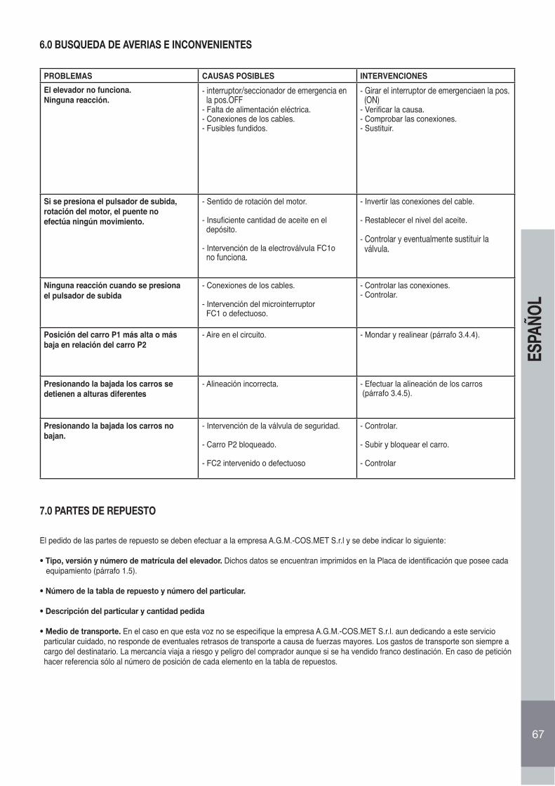
67
ESPA
ÑOL
6.0 BUSQUEDA DE AVERIAS E INCONVENIENTES
PROBLEMAS CAUSAS POSIBLES INTERVENCIONESEl elevador no funciona.Ninguna reacción.
- interruptor/seccionador de emergencia en la pos.OFF- Falta de alimentación eléctrica.- Conexiones de los cables.- Fusibles fundidos.
- Girar el interruptor de emergenciaen la pos. (ON)- Verificar la causa.- Comprobar las conexiones.- Sustituir.
Si se presiona el pulsador de subida,rotación del motor, el puente noefectúa ningún movimiento.
- Sentido de rotación del motor.
- Insuficiente cantidad de aceite en el depósito.
- Intervención de la electroválvula FC1o no funciona.
- Invertir las conexiones del cable.
- Restablecer el nivel del aceite.
- Controlar y eventualmente sustituir la válvula.
Ninguna reacción cuando se presionael pulsador de subida
- Conexiones de los cables.
- Intervención del microinterruptor FC1 o defectuoso.
- Controlar las conexiones.- Controlar.
Posición del carro P1 más alta o másbaja en relación del carro P2
- Aire en el circuito. - Mondar y realinear (párrafo 3.4.4).
Presionando la bajada los carros sedetienen a alturas diferentes
- Alineación incorrecta. - Efectuar la alineación de los carros (párrafo 3.4.5).
Presionando la bajada los carros no bajan.
- Intervención de la válvula de seguridad.
- Carro P2 bloqueado.
- FC2 intervenido o defectuoso
- Controlar.
- Subir y bloquear el carro.
- Controlar
7.0 PARTES DE REPUESTO
El pedido de las partes de repuesto se deben efectuar a la empresa A.G.M.-COS.MET S.r.l y se debe indicar lo siguiente:
• Tipo, versión y número de matrícula del elevador. Dichos datos se encuentran imprimidos en la Placa de identificación que posee cada equipamiento (párrafo 1.5).
• Número de la tabla de repuesto y número del particular.
• Descripción del particular y cantidad pedida
• Medio de transporte. En el caso en que esta voz no se especifique la empresa A.G.M.-COS.MET S.r.l. aun dedicando a este servicio particular cuidado, no responde de eventuales retrasos de transporte a causa de fuerzas mayores. Los gastos de transporte son siempre a cargo del destinatario. La mercancía viaja a riesgo y peligro del comprador aunque si se ha vendido franco destinación. En caso de petición hacer referencia sólo al número de posición de cada elemento en la tabla de repuestos.
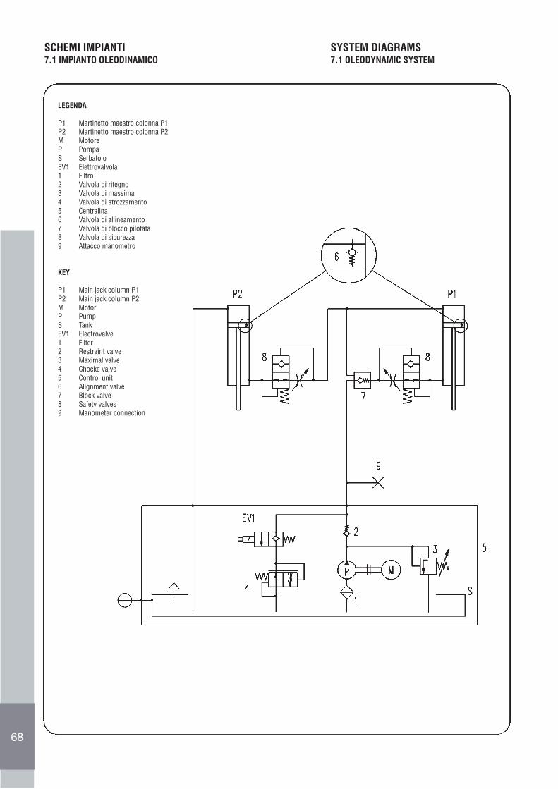
68
SCHEMI IMPIANTI7.1 IMPIANTO OLEODINAMICO
SYSTEM DIAGRAMS7.1 OLEODYNAMIC SYSTEM
LEGENDA
P1 Martinetto maestro colonna P1P2 Martinetto maestro colonna P2M MotoreP PompaS SerbatoioEV1 Elettrovalvola 1 Filtro2 Valvola di ritegno3 Valvola di massima4 Valvola di strozzamento5 Centralina6 Valvola di allineamento7 Valvola di blocco pilotata8 Valvola di sicurezza9 Attacco manometro
KEY
P1 Main jack column P1 P2 Main jack column P2 M MotorP PumpS TankEV1 Electrovalve 1 Filter2 Restraint valve3 Maximal valve4 Chocke valve5 Control unit6 Alignment valve7 Block valve 8 Safety valves9 Manometer connection
63
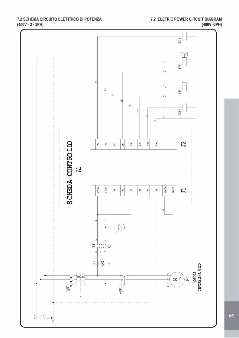
69
7.2 SCHEMA CIRCUITO ELETTRICO DI POTENZA(400V - 3 - 3PH)
7.2 ELETRIC POWER CIRCUIT DIAGRAM(400V -3PH)
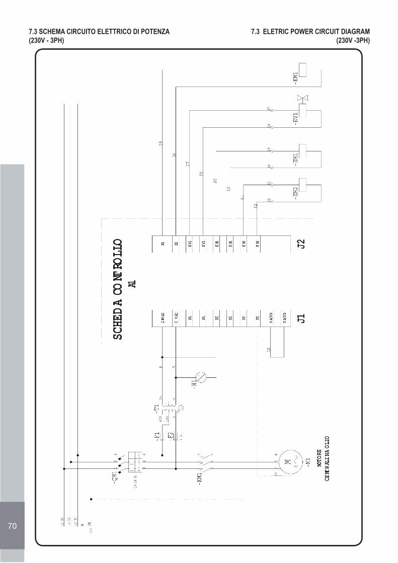
70
7.3 SCHEMA CIRCUITO ELETTRICO DI POTENZA(230V - 3PH)
7.3 ELETRIC POWER CIRCUIT DIAGRAM(230V -3PH)
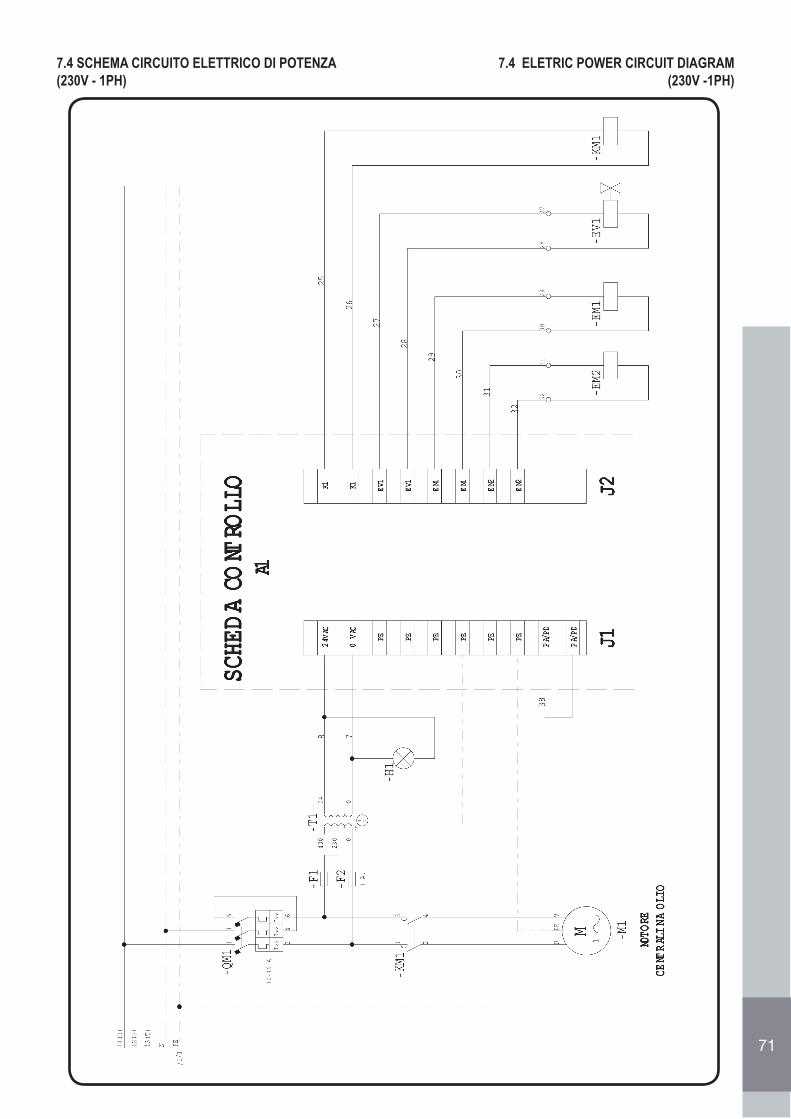
71
7.4 SCHEMA CIRCUITO ELETTRICO DI POTENZA(230V - 1PH)
7.4 ELETRIC POWER CIRCUIT DIAGRAM(230V -1PH)
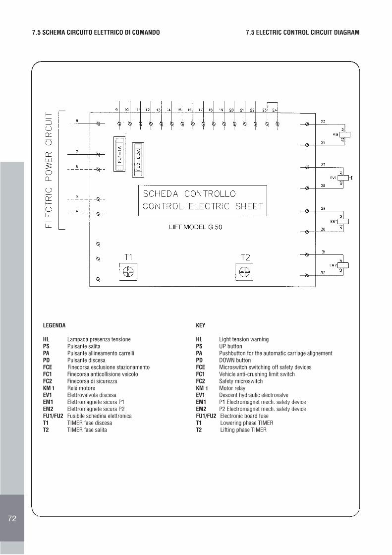
7267
7.5 SCHEMA CIRCUITO ELETTRICO DI COMANDO 7.5 ELECTRIC CONTROL CIRCUIT DIAGRAM
LEGENDA
HL Lampada presenza tensionePS Pulsante salitaPA Pulsante allineamento carrelliPD Pulsante discesaFCE Finecorsa esclusione stazionamentoFC1 Finecorsa anticollisione veicoloFC2 Finecorsa di sicurezzaKM Relé motoreEV1 Elettrovalvola discesaEM1 Elettromagnete sicura P1EM2 Elettromagnete sicura P2FU1/FU2 Fusibile schedina elettronicaT1 TIMER fase discesaT2 TIMER fase salita
KEY
HL Light tension warningPS UP buttonPA Pushbutton for the automatic carriage alignementPD DOWN buttonFCE Microswitch switching off safety devicesFC1 Vehicle anti-crushing limit switchFC2 Safety microswitchKM Motor relayEV1 Descent hydraulic electrovalveEM1 P1 Electromagnet mech. safety deviceEM2 P2 Electromagnet mech. safety deviceFU1/FU2 Electronic board fuseT1 Lowering phase TIMERT2 Lifting phase TIMER
1 1
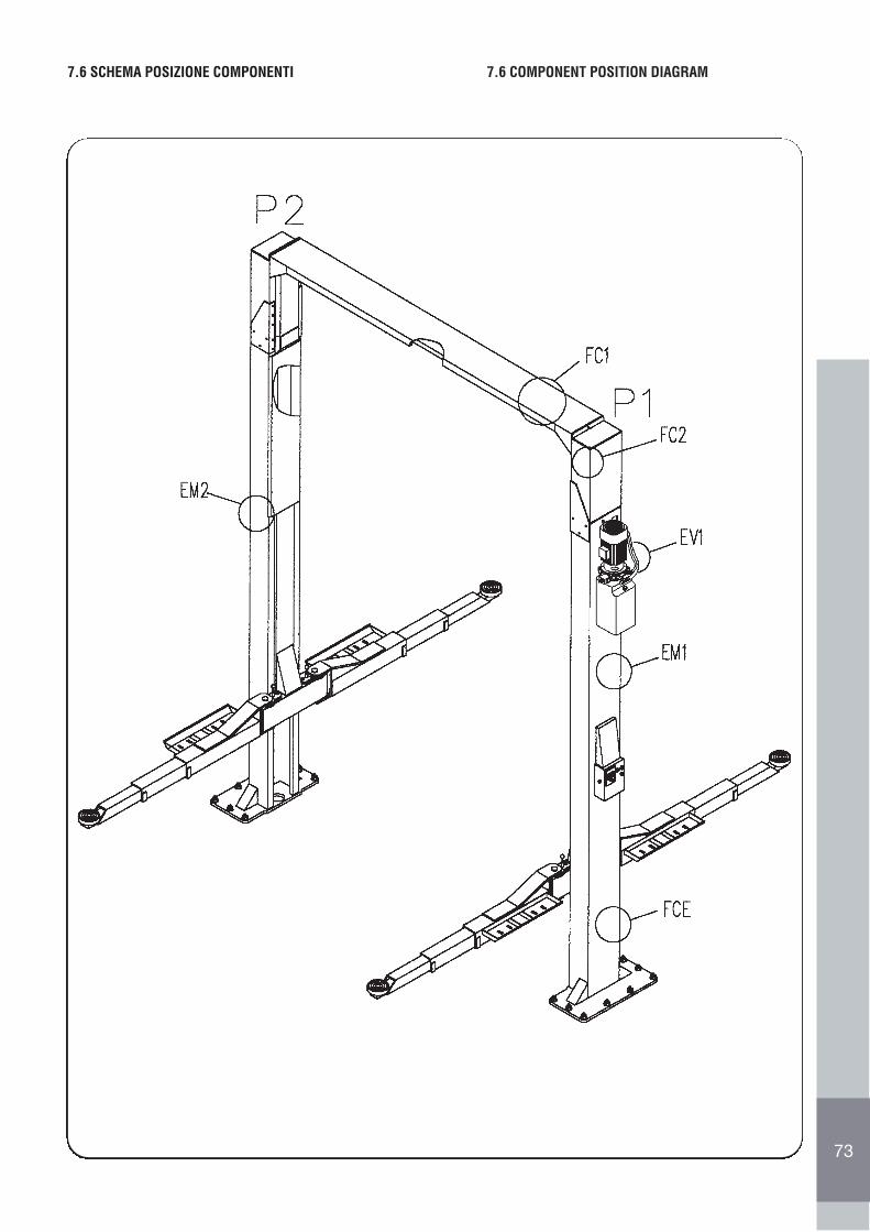
7368
7.6 SCHEMA POSIZIONE COMPONENTI 7.6 COMPONENT POSITION DIAGRAM
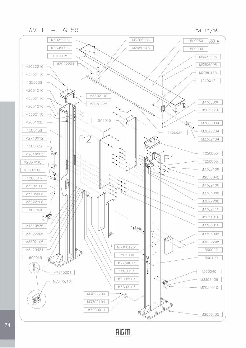
74
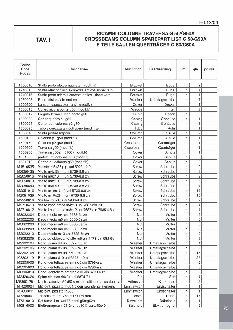
1200016 Staffa porta elettromagnete (modif. a) Bracket Bügel n. 21210015 Staffa attacco fisso sicurezza anticollisione vern. Bracket Bügel n. 11210016 Staffa porta micro sicurezza anticollisione vern. Bracket Bügel n. 11250003 Rond. distanziale motore Washer Unterlagscheibe n. 41250800 Lam. chiu.sup.colonna p1 (modif.l) Cover Deckel n. 21500015 Cuneo sicura ponte g50 (modif.b) Wedge Keil n. 21500017 Piegato ferma cuneo ponte g50 Curve Bogen n. 21500022 Carter quadro el. g50 Casing Gehäuse n. 11500023 Carter est. colonna p2 g50 Casing Gehäuse n. 11500035 Tubo sicurezza anticollisione (modif. a) Tube Rohr n. 11500040 Staffa porta-tamponi Column Säule n. 21500100 Colonna p1 g50 (modif.f) Column Säule n. 11500150 Colonna p2 g50 (modif.c) Crossbeam Querträger n. 11500900 Traversa g50 (modif.b) Crossbeam Querträger n. 11500950 Traversa g50a l=3100 (modif.b) Cover Schutz n. 11501000 protez. int. colonna g50 (modif.f) Cover Schutz n. 21501010 Carter int. colonna g50 (modif.b) Cover Schutz n. 2
M1510535 Vte stei m5x35 p.p. uni 5923-12.9 Screw Schraube n. 2M2050435 Vte te m4x35 i.f. uni 5739-8.8 zn Screw Schraube n. 5M2050616 Vte te m6x16 i.f. uni 5739-8.8 zn Screw Schraube n. 2M2050810 Vte te m8x10 i.f. uni 5739-8.8 zn Screw Schraube n. 6M2050840 Vte te m8x40 i.f. uni 5739-8.8 zn Screw Schraube n. 4M2051016 Vte te m10x16 i.f. uni 5739-8.8 zn Screw Schraube n. 14M2051025 Vte te m10x25 i.f uni 5739-8.8 zn. Screw Schraube n. 10M2250616 Vte tsei m6x16 uni 5933-8.8 zn Screw Schraube n. 2M2710410 Vte tc impr. croce m4x10 uni 7687/din 79 Screw Schraube n. 4M2710812 Vte tc impr. croce m8x12 uni 7687-din 7985 4.8 zn Screw Schraube n. 4M3022204 Dado medio m4 uni 5588-6s zn Nut Mutter n. 6M3022205 Dado medio m5 uni 5588-5s zn Nut Mutter n. 6M3022206 Dado medio m6 uni 5588-6s zn Nut Mutter n. 3M3022208 Dado medio m8 uni 5588-6s zn Nut Mutter n. 6M3022210 Dado medio m10 uni 5588-5s zn Nut Mutter n. 2M3082205 Dado autobloccante alto m5 uni 7473-din 982-5s Nut Mutter n. 2M3302104 Rond. piana d4 uni 6592-r40 zn Washer Unterlagscheibe n. 4M3302106 Rond. piana d6 uni 6592-r40 zn Washer Unterlagscheibe n. 2M3302108 Rond. piana d8 uni 6592-r40 zn Washer Unterlagscheibe n. 16M3302110 Rond. piana d10 uni 6592-r40 zn Washer Unterlagscheibe n. 26M3305006 Rond. dentellata esterna d6 din 6798-a zn Washer Unterlagscheibe n. 3M3305008 Rond. dentellata esterna d8 din 6798-a zn Washer Unterlagscheibe n. 6M3305010 Rond. dentellata esterna d10 din 6798-a zn Washer Unterlagscheibe n. 8M3420424 Spina elastica d4x24 uni 6874-71 Pin Stift n. 4
M68001251 Nastro adesivo 50x50 sp=1 polietilene bassa densita Adhesive Klebeband n. 2M7000004 Microint. pizzato fr 654 o corrispondente siemens Limit switch Endschalter n. 1M7000011 Microint. pizzato fr 655 Limit switch Endschalter n. 1M7340001 Tassello fm art. 753 m16x175 mm. Dowel Dübel n. 16M7310010 Set tasselli m16x175 ponti g50/g50a Dowel set Dübelsatz n. 1M9816003 Elettromagn.cm.25-24v- ed30% carc.40x40 Solenoid Elektromagnet n. 2
TAV. IRICAMBI COLONNE TRAVERSA G 50//G50A
CROSSBEAMS COLUMN SPAREPART LIST G 50/G50AE-TEILE SÄULEN QUERTRÄGER G 50/G50A
Ed.12/06
CodiceCodeKodex
Descrizione Description Beschreibung um qta posdis
75
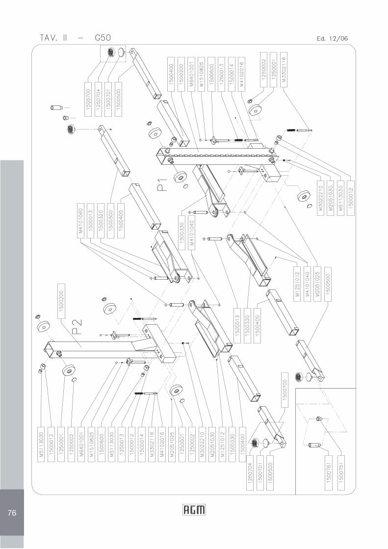
76
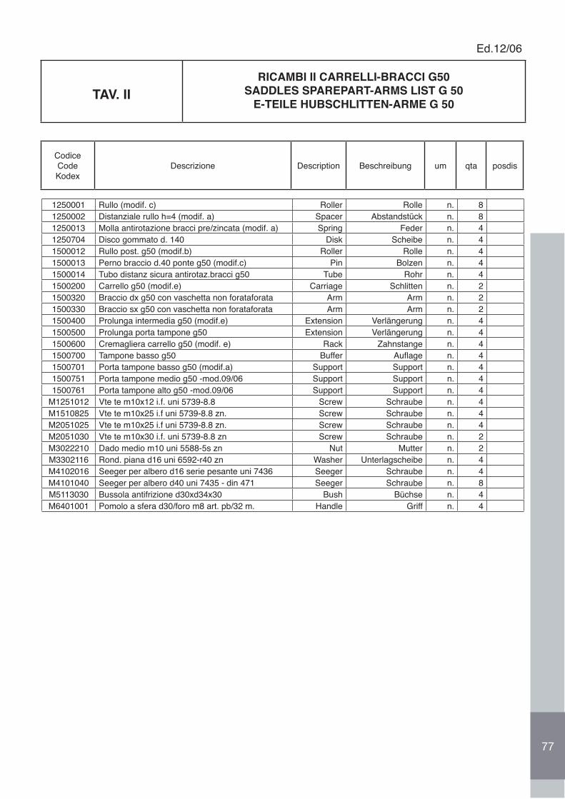
1250001 Rullo (modif. c) Roller Rolle n. 81250002 Distanziale rullo h=4 (modif. a) Spacer Abstandstück n. 81250013 Molla antirotazione bracci pre/zincata (modif. a) Spring Feder n. 41250704 Disco gommato d. 140 Disk Scheibe n. 41500012 Rullo post. g50 (modif.b) Roller Rolle n. 41500013 Perno braccio d.40 ponte g50 (modif.c) Pin Bolzen n. 41500014 Tubo distanz sicura antirotaz.bracci g50 Tube Rohr n. 41500200 Carrello g50 (modif.e) Carriage Schlitten n. 21500320 Braccio dx g50 con vaschetta non forataforata Arm Arm n. 21500330 Braccio sx g50 con vaschetta non forataforata Arm Arm n. 21500400 Prolunga intermedia g50 (modif.e) Extension Verlängerung n. 41500500 Prolunga porta tampone g50 Extension Verlängerung n. 41500600 Cremagliera carrello g50 (modif. e) Rack Zahnstange n. 41500700 Tampone basso g50 Buffer Auflage n. 41500701 Porta tampone basso g50 (modif.a) Support Support n. 41500751 Porta tampone medio g50 -mod.09/06 Support Support n. 41500761 Porta tampone alto g50 -mod.09/06 Support Support n. 4
M1251012 Vte te m10x12 i.f. uni 5739-8.8 Screw Schraube n. 4M1510825 Vte te m10x25 i.f uni 5739-8.8 zn. Screw Schraube n. 4M2051025 Vte te m10x25 i.f uni 5739-8.8 zn. Screw Schraube n. 4M2051030 Vte te m10x30 i.f. uni 5739-8.8 zn Screw Schraube n. 2M3022210 Dado medio m10 uni 5588-5s zn Nut Mutter n. 2M3302116 Rond. piana d16 uni 6592-r40 zn Washer Unterlagscheibe n. 4M4102016 Seeger per albero d16 serie pesante uni 7436 Seeger Schraube n. 4M4101040 Seeger per albero d40 uni 7435 - din 471 Seeger Schraube n. 8M5113030 Bussola antifrizione d30xd34x30 Bush Büchse n. 4M6401001 Pomolo a sfera d30/foro m8 art. pb/32 m. Handle Griff n. 4
TAV. IIRICAMBI II CARRELLI-BRACCI G50
SADDLES SPAREPART-ARMS LIST G 50E-TEILE HUBSCHLITTEN-ARME G 50
Ed.12/06
CodiceCodeKodex
Descrizione Description Beschreibung um qta posdis
77
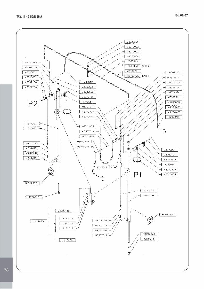
TAV. III - G 50/G 50 A Ed. 04/03
74
Ed.06/07
M3311111
M3311111
78
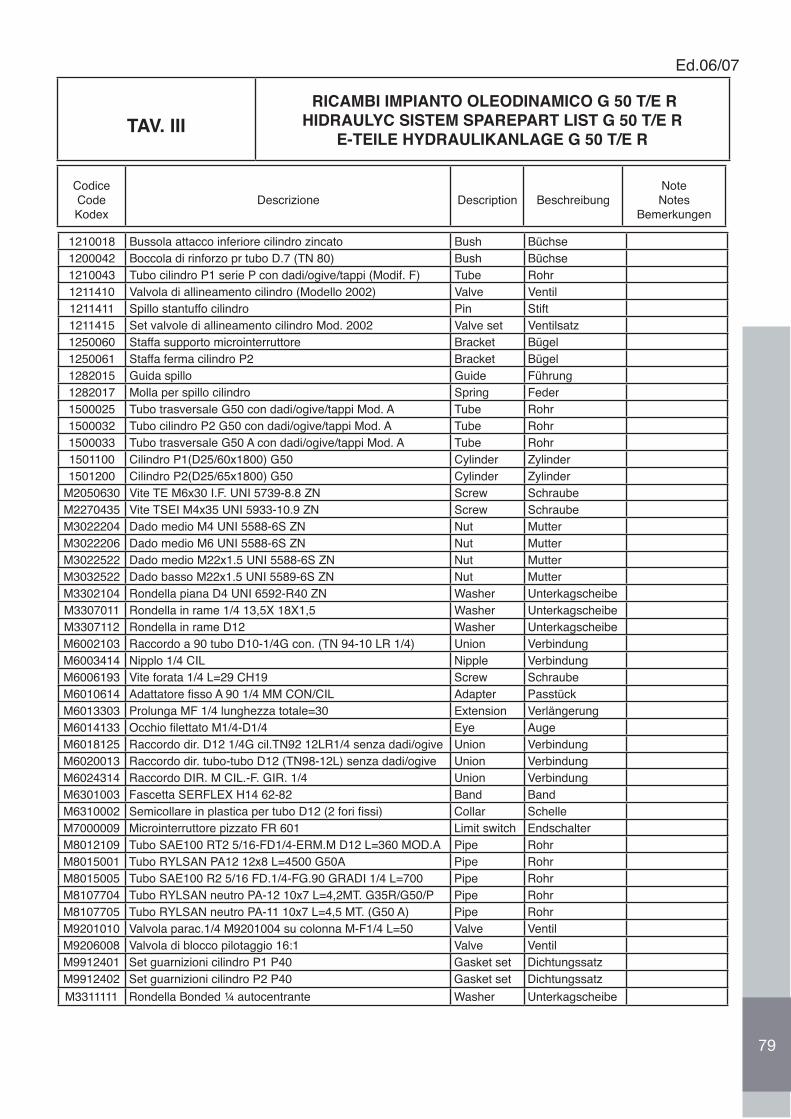
TAV. III RICAMBI IMPIANTO OLEODINAMICO G 50 T/E R
HIDRAULYC SISTEM SPAREPART LIST G 50 T/E RE-TEILE HYDRAULIKANLAGE G 50 T/E R
Ed.06/07
CodiceCodeKodex
Descrizione Description BeschreibungNoteNotes
Bemerkungen
1210018 Bussola attacco inferiore cilindro zincato Bush Büchse1200042 Boccola di rinforzo pr tubo D.7 (TN 80) Bush Büchse1210043 Tubo cilindro P1 serie P con dadi/ogive/tappi (Modif. F) Tube Rohr1211410 Valvola di allineamento cilindro (Modello 2002) Valve Ventil1211411 Spillo stantuffo cilindro Pin Stift1211415 Set valvole di allineamento cilindro Mod. 2002 Valve set Ventilsatz1250060 Staffa supporto microinterruttore Bracket Bügel1250061 Staffa ferma cilindro P2 Bracket Bügel1282015 Guida spillo Guide Führung1282017 Molla per spillo cilindro Spring Feder1500025 Tubo trasversale G50 con dadi/ogive/tappi Mod. A Tube Rohr1500032 Tubo cilindro P2 G50 con dadi/ogive/tappi Mod. A Tube Rohr1500033 Tubo trasversale G50 A con dadi/ogive/tappi Mod. A Tube Rohr1501100 Cilindro P1(D25/60x1800) G50 Cylinder Zylinder1501200 Cilindro P2(D25/65x1800) G50 Cylinder Zylinder
M2050630 Vite TE M6x30 I.F. UNI 5739-8.8 ZN Screw SchraubeM2270435 Vite TSEI M4x35 UNI 5933-10.9 ZN Screw SchraubeM3022204 Dado medio M4 UNI 5588-6S ZN Nut MutterM3022206 Dado medio M6 UNI 5588-6S ZN Nut MutterM3022522 Dado medio M22x1.5 UNI 5588-6S ZN Nut MutterM3032522 Dado basso M22x1.5 UNI 5589-6S ZN Nut MutterM3302104 Rondella piana D4 UNI 6592-R40 ZN Washer UnterkagscheibeM3307011 Rondella in rame 1/4 13,5X 18X1,5 Washer UnterkagscheibeM3307112 Rondella in rame D12 Washer UnterkagscheibeM6002103 Raccordo a 90 tubo D10-1/4G con. (TN 94-10 LR 1/4) Union VerbindungM6003414 Nipplo 1/4 CIL Nipple VerbindungM6006193 Vite forata 1/4 L=29 CH19 Screw SchraubeM6010614 Adattatore fisso A 90 1/4 MM CON/CIL Adapter PasstückM6013303 Prolunga MF 1/4 lunghezza totale=30 Extension VerlängerungM6014133 Occhio filettato M1/4-D1/4 Eye AugeM6018125 Raccordo dir. D12 1/4G cil.TN92 12LR1/4 senza dadi/ogive Union VerbindungM6020013 Raccordo dir. tubo-tubo D12 (TN98-12L) senza dadi/ogive Union VerbindungM6024314 Raccordo DIR. M CIL.-F. GIR. 1/4 Union VerbindungM6301003 Fascetta SERFLEX H14 62-82 Band BandM6310002 Semicollare in plastica per tubo D12 (2 fori fissi) Collar SchelleM7000009 Microinterruttore pizzato FR 601 Limit switch EndschalterM8012109 Tubo SAE100 RT2 5/16-FD1/4-ERM.M D12 L=360 MOD.A Pipe RohrM8015001 Tubo RYLSAN PA12 12x8 L=4500 G50A Pipe RohrM8015005 Tubo SAE100 R2 5/16 FD.1/4-FG.90 GRADI 1/4 L=700 Pipe RohrM8107704 Tubo RYLSAN neutro PA-12 10x7 L=4,2MT. G35R/G50/P Pipe RohrM8107705 Tubo RYLSAN neutro PA-11 10x7 L=4,5 MT. (G50 A) Pipe RohrM9201010 Valvola parac.1/4 M9201004 su colonna M-F1/4 L=50 Valve VentilM9206008 Valvola di blocco pilotaggio 16:1 Valve VentilM9912401 Set guarnizioni cilindro P1 P40 Gasket set DichtungssatzM9912402 Set guarnizioni cilindro P2 P40 Gasket set DichtungssatzM3311111 Rondella Bonded ¼ autocentrante Washer Unterkagscheibe
79
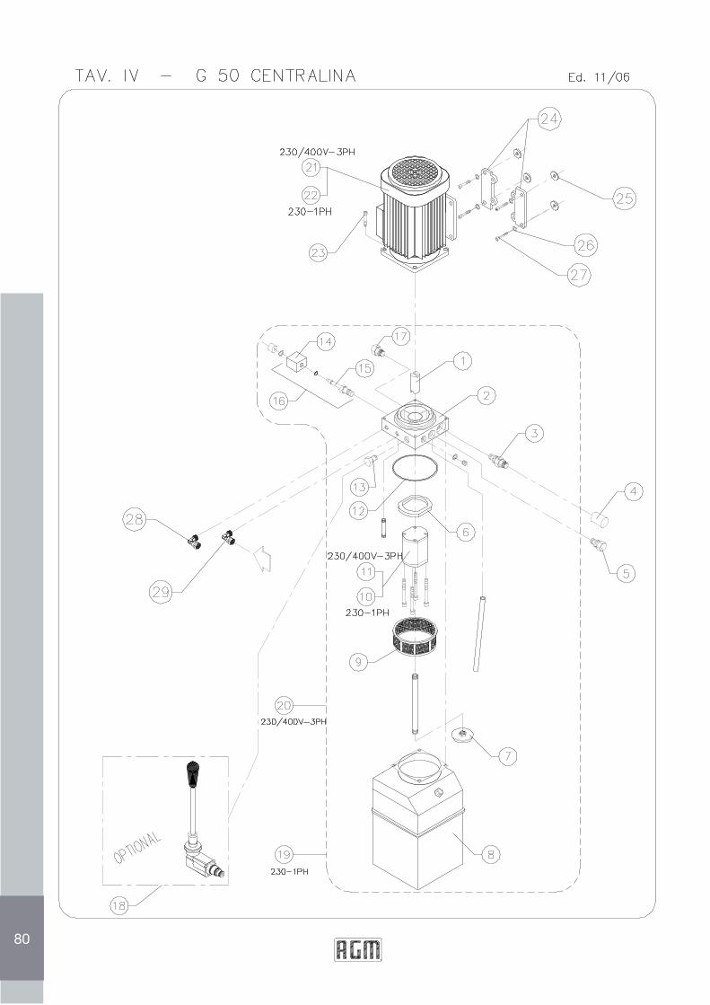
80
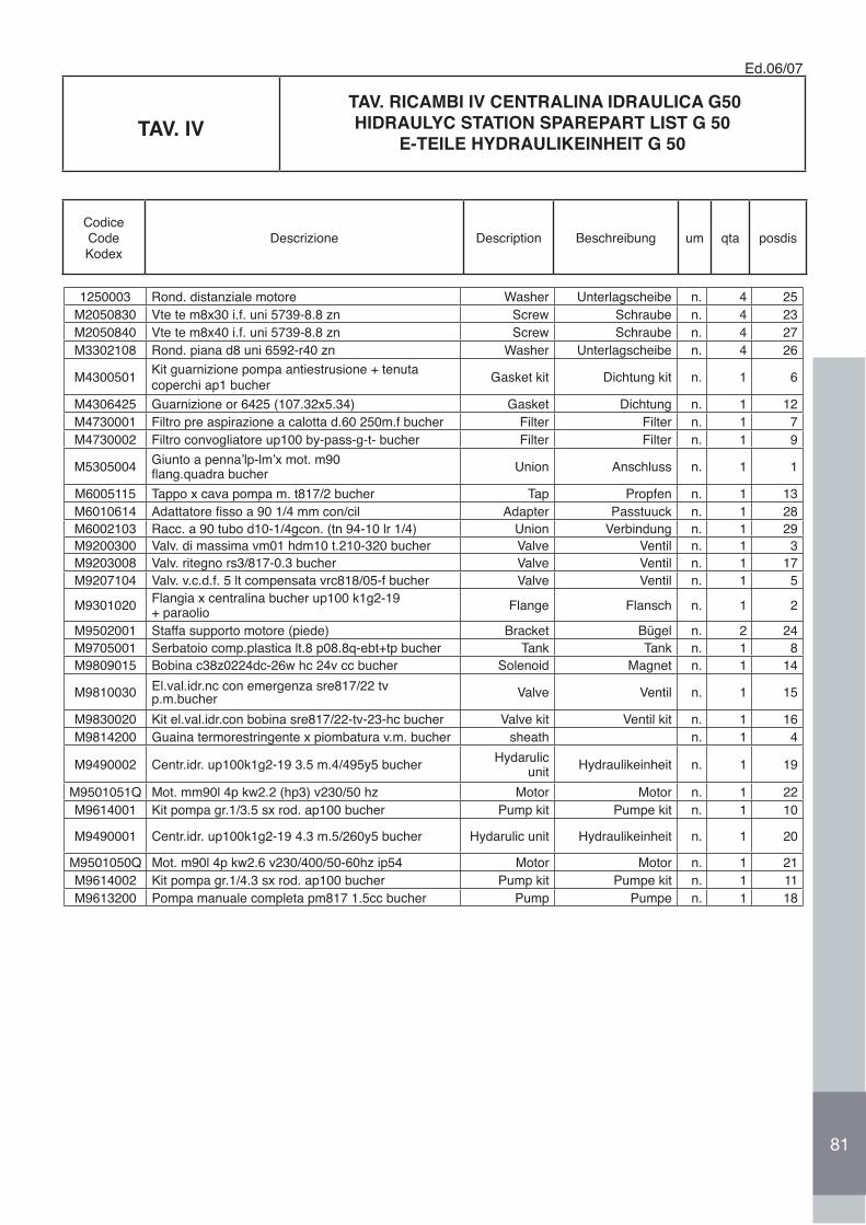
TAV. IV TAV. RICAMBI IV CENTRALINA IDRAULICA G50
HIDRAULYC STATION SPAREPART LIST G 50E-TEILE HYDRAULIKEINHEIT G 50
Ed.06/07
CodiceCodeKodex
Descrizione Description Beschreibung um qta posdis
1250003 Rond. distanziale motore Washer Unterlagscheibe n. 4 25M2050830 Vte te m8x30 i.f. uni 5739-8.8 zn Screw Schraube n. 4 23M2050840 Vte te m8x40 i.f. uni 5739-8.8 zn Screw Schraube n. 4 27M3302108 Rond. piana d8 uni 6592-r40 zn Washer Unterlagscheibe n. 4 26
M4300501 Kit guarnizione pompa antiestrusione + tenuta coperchi ap1 bucher Gasket kit Dichtung kit n. 1 6
M4306425 Guarnizione or 6425 (107.32x5.34) Gasket Dichtung n. 1 12M4730001 Filtro pre aspirazione a calotta d.60 250m.f bucher Filter Filter n. 1 7M4730002 Filtro convogliatore up100 by-pass-g-t- bucher Filter Filter n. 1 9
M5305004 Giunto a penna’lp-lm’x mot. m90flang.quadra bucher Union Anschluss n. 1 1
M6005115 Tappo x cava pompa m. t817/2 bucher Tap Propfen n. 1 13M6010614 Adattatore fisso a 90 1/4 mm con/cil Adapter Passtuuck n. 1 28M6002103 Racc. a 90 tubo d10-1/4gcon. (tn 94-10 lr 1/4) Union Verbindung n. 1 29M9200300 Valv. di massima vm01 hdm10 t.210-320 bucher Valve Ventil n. 1 3M9203008 Valv. ritegno rs3/817-0.3 bucher Valve Ventil n. 1 17M9207104 Valv. v.c.d.f. 5 lt compensata vrc818/05-f bucher Valve Ventil n. 1 5
M9301020 Flangia x centralina bucher up100 k1g2-19+ paraolio Flange Flansch n. 1 2
M9502001 Staffa supporto motore (piede) Bracket Bügel n. 2 24M9705001 Serbatoio comp.plastica lt.8 p08.8q-ebt+tp bucher Tank Tank n. 1 8M9809015 Bobina c38z0224dc-26w hc 24v cc bucher Solenoid Magnet n. 1 14
M9810030 El.val.idr.nc con emergenza sre817/22 tv p.m.bucher Valve Ventil n. 1 15
M9830020 Kit el.val.idr.con bobina sre817/22-tv-23-hc bucher Valve kit Ventil kit n. 1 16M9814200 Guaina termorestringente x piombatura v.m. bucher sheath n. 1 4
M9490002 Centr.idr. up100k1g2-19 3.5 m.4/495y5 bucher Hydarulicunit Hydraulikeinheit n. 1 19
M9501051Q Mot. mm90l 4p kw2.2 (hp3) v230/50 hz Motor Motor n. 1 22M9614001 Kit pompa gr.1/3.5 sx rod. ap100 bucher Pump kit Pumpe kit n. 1 10
M9490001 Centr.idr. up100k1g2-19 4.3 m.5/260y5 bucher Hydarulic unit Hydraulikeinheit n. 1 20
M9501050Q Mot. m90l 4p kw2.6 v230/400/50-60hz ip54 Motor Motor n. 1 21M9614002 Kit pompa gr.1/4.3 sx rod. ap100 bucher Pump kit Pumpe kit n. 1 11M9613200 Pompa manuale completa pm817 1.5cc bucher Pump Pumpe n. 1 18
81
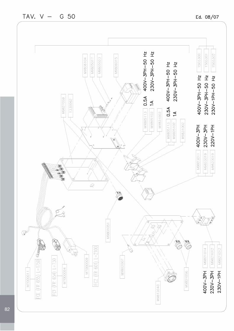
82
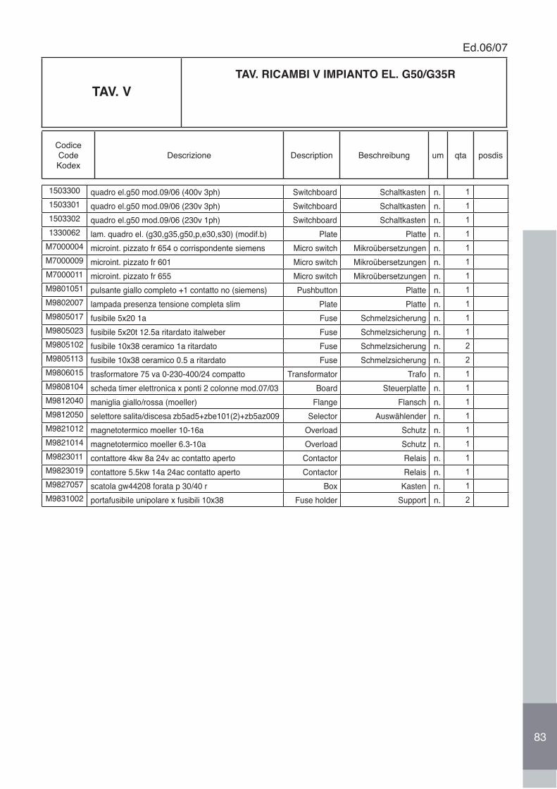
TAV. V TAV. RICAMBI V IMPIANTO EL. G50/G35R
Ed.06/07
CodiceCodeKodex
Descrizione Description Beschreibung um qta posdis
83
1503300 quadro el.g50 mod.09/06 (400v 3ph) Switchboard Schaltkasten n. 1
1503301 quadro el.g50 mod.09/06 (230v 3ph) Switchboard Schaltkasten n. 1
1503302 quadro el.g50 mod.09/06 (230v 1ph) Switchboard Schaltkasten n. 1
1330062 lam. quadro el. (g30,g35,g50,p,e30,s30) (modif.b) Plate Platte n. 1
M7000004 microint. pizzato fr 654 o corrispondente siemens Micro switch Mikroübersetzungen n. 1
M7000009 microint. pizzato fr 601 Micro switch Mikroübersetzungen n. 1
M7000011 microint. pizzato fr 655 Micro switch Mikroübersetzungen n. 1
M9801051 pulsante giallo completo +1 contatto no (siemens) Pushbutton Platte n. 1
M9802007 lampada presenza tensione completa slim Plate Platte n. 1
M9805017 fusibile 5x20 1a Fuse Schmelzsicherung n. 1
M9805023 fusibile 5x20t 12.5a ritardato italweber Fuse Schmelzsicherung n. 1
M9805102 fusibile 10x38 ceramico 1a ritardato Fuse Schmelzsicherung n. 2
M9805113 fusibile 10x38 ceramico 0.5 a ritardato Fuse Schmelzsicherung n. 2
M9806015 trasformatore 75 va 0-230-400/24 compatto Transformator Trafo n. 1
M9808104 scheda timer elettronica x ponti 2 colonne mod.07/03 Board Steuerplatte n. 1
M9812040 maniglia giallo/rossa (moeller) Flange Flansch n. 1
M9812050 selettore salita/discesa zb5ad5+zbe101(2)+zb5az009 Selector Auswählender n. 1
M9821012 magnetotermico moeller 10-16a Overload Schutz n. 1
M9821014 magnetotermico moeller 6.3-10a Overload Schutz n. 1
M9823011 contattore 4kw 8a 24v ac contatto aperto Contactor Relais n. 1
M9823019 contattore 5.5kw 14a 24ac contatto aperto Contactor Relais n. 1
M9827057 scatola gw44208 forata p 30/40 r Box Kasten n. 1
M9831002 portafusibile unipolare x fusibili 10x38 Fuse holder Support n. 2
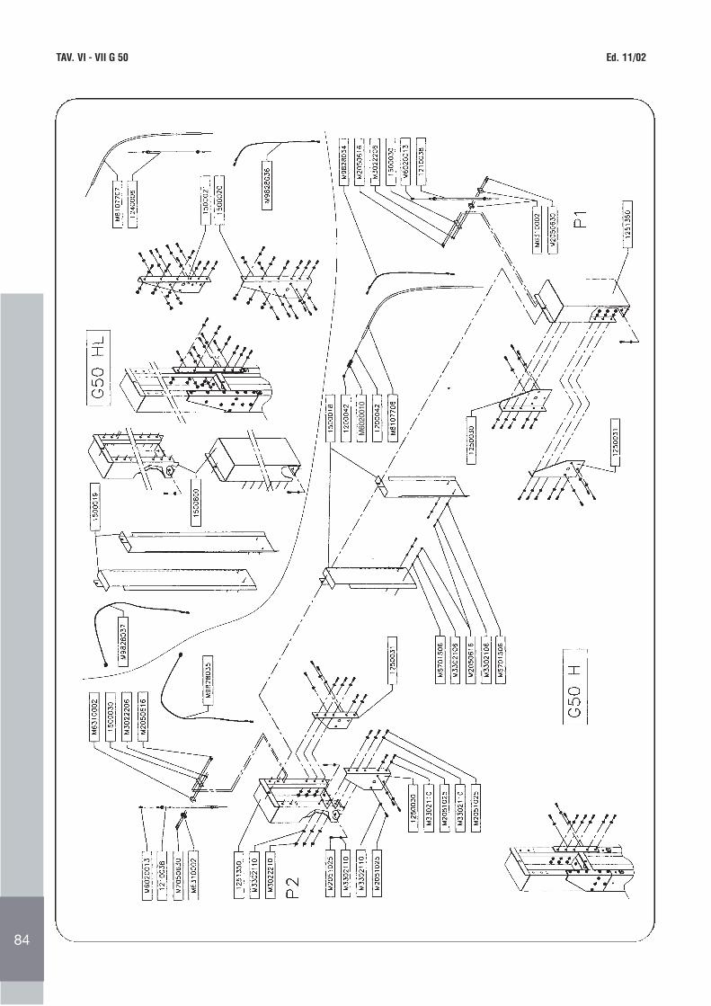
TAV. VI - VII G 50 Ed. 11/02
80
M60
2001
0
84
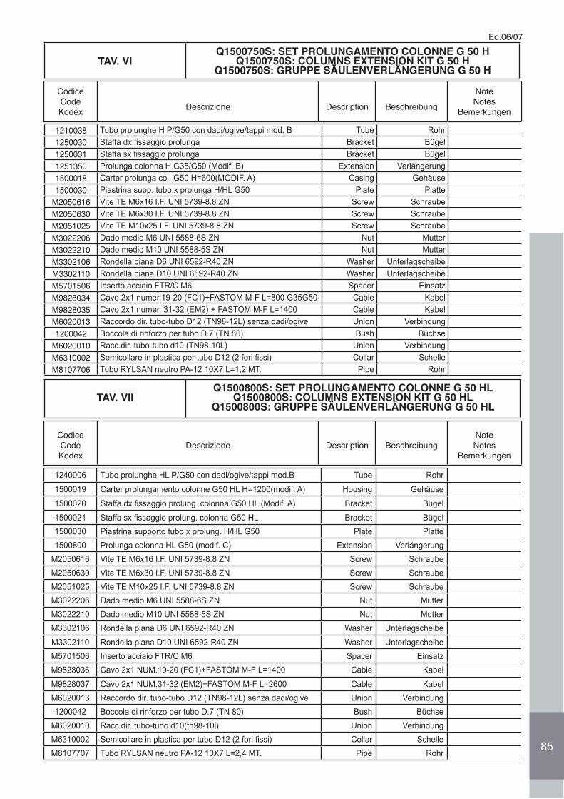
Ed.06/07
85
TAV. VIQ1500750S: SET PROLUNGAMENTO COLONNE G 50 H
Q1500750S: COLUMNS EXTENSION KIT G 50 HQ1500750S: GRUPPE SÄULENVERLÄNGERUNG G 50 H
CodiceCodeKodex Descrizione Description Beschreibung
NoteNotes
Bemerkungen
1210038 Tubo prolunghe H P/G50 con dadi/ogive/tappi mod. B Tube Rohr
1250030 Staffa dx fissaggio prolunga Bracket Bügel
1250031 Staffa sx fissaggio prolunga Bracket Bügel
1251350 Prolunga colonna H G35/G50 (Modif. B) Extension Verlängerung
1500018 Carter prolunga col. G50 H=600(MODIF. A) Casing Gehäuse
1500030 Piastrina supp. tubo x prolunga H/HL G50 Plate Platte
M2050616 Vite TE M6x16 I.F. UNI 5739-8.8 ZN Screw Schraube
M2050630 Vite TE M6x30 I.F. UNI 5739-8.8 ZN Screw Schraube
M2051025 Vite TE M10x25 I.F. UNI 5739-8.8 ZN Screw Schraube
M3022206 Dado medio M6 UNI 5588-6S ZN Nut Mutter
M3022210 Dado medio M10 UNI 5588-5S ZN Nut Mutter
M3302106 Rondella piana D6 UNI 6592-R40 ZN Washer Unterlagscheibe
M3302110 Rondella piana D10 UNI 6592-R40 ZN Washer Unterlagscheibe
M5701506 Inserto acciaio FTR/C M6 Spacer Einsatz
M9828034 Cavo 2x1 numer.19-20 (FC1)+FASTOM M-F L=800 G35G50 Cable Kabel
M9828035 Cavo 2x1 numer. 31-32 (EM2) + FASTOM M-F L=1400 Cable Kabel
M6020013 Raccordo dir. tubo-tubo D12 (TN98-12L) senza dadi/ogive Union Verbindung
1200042 Boccola di rinforzo per tubo D.7 (TN 80) Bush Büchse
M6020010 Racc.dir. tubo-tubo d10 (TN98-10L) Union Verbindung
M6310002 Semicollare in plastica per tubo D12 (2 fori fissi) Collar Schelle
M8107706 Tubo RYLSAN neutro PA-12 10X7 L=1,2 MT. Pipe Rohr
TAV. VIIQ1500800S: SET PROLUNGAMENTO COLONNE G 50 HL
Q1500800S: COLUMNS EXTENSION KIT G 50 HLQ1500800S: GRUPPE SÄULENVERLÄNGERUNG G 50 HL
CodiceCodeKodex
Descrizione Description BeschreibungNoteNotes
Bemerkungen
1240006 Tubo prolunghe HL P/G50 con dadi/ogive/tappi mod.B Tube Rohr
1500019 Carter prolungamento colonne G50 HL H=1200(modif. A) Housing Gehäuse
1500020 Staffa dx fissaggio prolung. colonna G50 HL (Modif. A) Bracket Bügel
1500021 Staffa sx fissaggio prolung. colonna G50 HL Bracket Bügel
1500030 Piastrina supporto tubo x prolung. H/HL G50 Plate Platte
1500800 Prolunga colonna HL G50 (modif. C) Extension Verlängerung
M2050616 Vite TE M6x16 I.F. UNI 5739-8.8 ZN Screw Schraube
M2050630 Vite TE M6x30 I.F. UNI 5739-8.8 ZN Screw Schraube
M2051025 Vite TE M10x25 I.F. UNI 5739-8.8 ZN Screw Schraube
M3022206 Dado medio M6 UNI 5588-6S ZN Nut Mutter
M3022210 Dado medio M10 UNI 5588-5S ZN Nut Mutter
M3302106 Rondella piana D6 UNI 6592-R40 ZN Washer Unterlagscheibe
M3302110 Rondella piana D10 UNI 6592-R40 ZN Washer Unterlagscheibe
M5701506 Inserto acciaio FTR/C M6 Spacer Einsatz
M9828036 Cavo 2x1 NUM.19-20 (FC1)+FASTOM M-F L=1400 Cable Kabel
M9828037 Cavo 2x1 NUM.31-32 (EM2)+FASTOM M-F L=2600 Cable Kabel
M6020013 Raccordo dir. tubo-tubo D12 (TN98-12L) senza dadi/ogive Union Verbindung
1200042 Boccola di rinforzo per tubo D.7 (TN 80) Bush Büchse
M6020010 Racc.dir. tubo-tubo d10(tn98-10l) Union Verbindung
M6310002 Semicollare in plastica per tubo D12 (2 fori fissi) Collar Schelle
M8107707 Tubo RYLSAN neutro PA-12 10X7 L=2,4 MT. Pipe Rohr
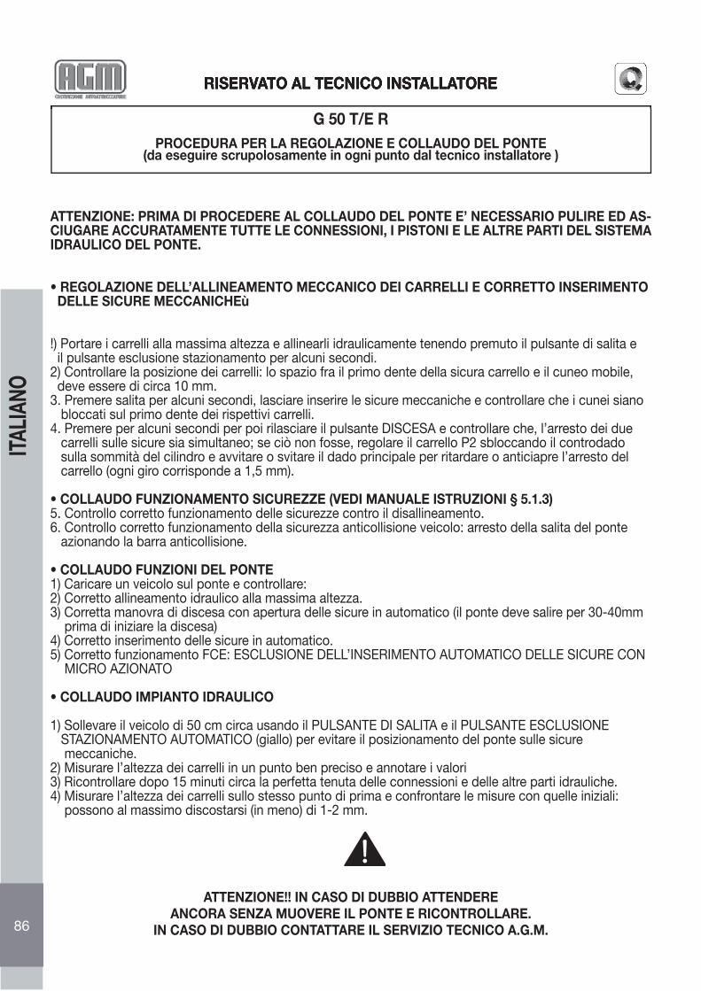
RISERVATO AL TECNICO INSTALLATORE
G 50 T/E RPROCEDURA PER LA REGOLAZIONE E COLLAUDO DEL PONTE
(da eseguire scrupolosamente in ogni punto dal tecnico installatore )
ATTENZIONE: PRIMA DI PROCEDERE AL COLLAUDO DEL PONTE E’ NECESSARIO PULIRE ED AS-CIUGARE ACCURATAMENTE TUTTE LE CONNESSIONI, I PISTONI E LE ALTRE PARTI DEL SISTEMA IDRAULICO DEL PONTE.
• REGOLAZIONE DELL’ALLINEAMENTO MECCANICO DEI CARRELLI E CORRETTO INSERIMENTO DELLE SICURE MECCANICHEù
!) Portare i carrelli alla massima altezza e allinearli idraulicamente tenendo premuto il pulsante di salita e il pulsante esclusione stazionamento per alcuni secondi.2) Controllare la posizione dei carrelli: lo spazio fra il primo dente della sicura carrello e il cuneo mobile, deve essere di circa 10 mm.3. Premere salita per alcuni secondi, lasciare inserire le sicure meccaniche e controllare che i cunei siano bloccati sul primo dente dei rispettivi carrelli.4. Premere per alcuni secondi per poi rilasciare il pulsante DISCESA e controllare che, l’arresto dei due carrelli sulle sicure sia simultaneo; se ciò non fosse, regolare il carrello P2 sbloccando il controdado sulla sommità del cilindro e avvitare o svitare il dado principale per ritardare o anticiapre l’arresto del carrello (ogni giro corrisponde a 1,5 mm).
• COLLAUDO FUNZIONAMENTO SICUREZZE (VEDI MANUALE ISTRUZIONI § 5.1.3)5. Controllo corretto funzionamento delle sicurezze contro il disallineamento.6. Controllo corretto funzionamento della sicurezza anticollisione veicolo: arresto della salita del ponte azionando la barra anticollisione.
• COLLAUDO FUNZIONI DEL PONTE1) Caricare un veicolo sul ponte e controllare:2) Corretto allineamento idraulico alla massima altezza.3) Corretta manovra di discesa con apertura delle sicure in automatico (il ponte deve salire per 30-40mm prima di iniziare la discesa)4) Corretto inserimento delle sicure in automatico.5) Corretto funzionamento FCE: ESCLUSIONE DELL’INSERIMENTO AUTOMATICO DELLE SICURE CON MICRO AZIONATO
• COLLAUDO IMPIANTO IDRAULICO
1) Sollevare il veicolo di 50 cm circa usando il PULSANTE DI SALITA e il PULSANTE ESCLUSIONE STAZIONAMENTO AUTOMATICO (giallo) per evitare il posizionamento del ponte sulle sicure meccaniche.2) Misurare l’altezza dei carrelli in un punto ben preciso e annotare i valori3) Ricontrollare dopo 15 minuti circa la perfetta tenuta delle connessioni e delle altre parti idrauliche.4) Misurare l’altezza dei carrelli sullo stesso punto di prima e confrontare le misure con quelle iniziali: possono al massimo discostarsi (in meno) di 1-2 mm.
ATTENZIONE!! IN CASO DI DUBBIO ATTENDEREANCORA SENZA MUOVERE IL PONTE E RICONTROLLARE.
IN CASO DI DUBBIO CONTATTARE IL SERVIZIO TECNICO A.G.M.
RISERVATO AL TECNICO INSTALLATORE
86
ITAL
IANO
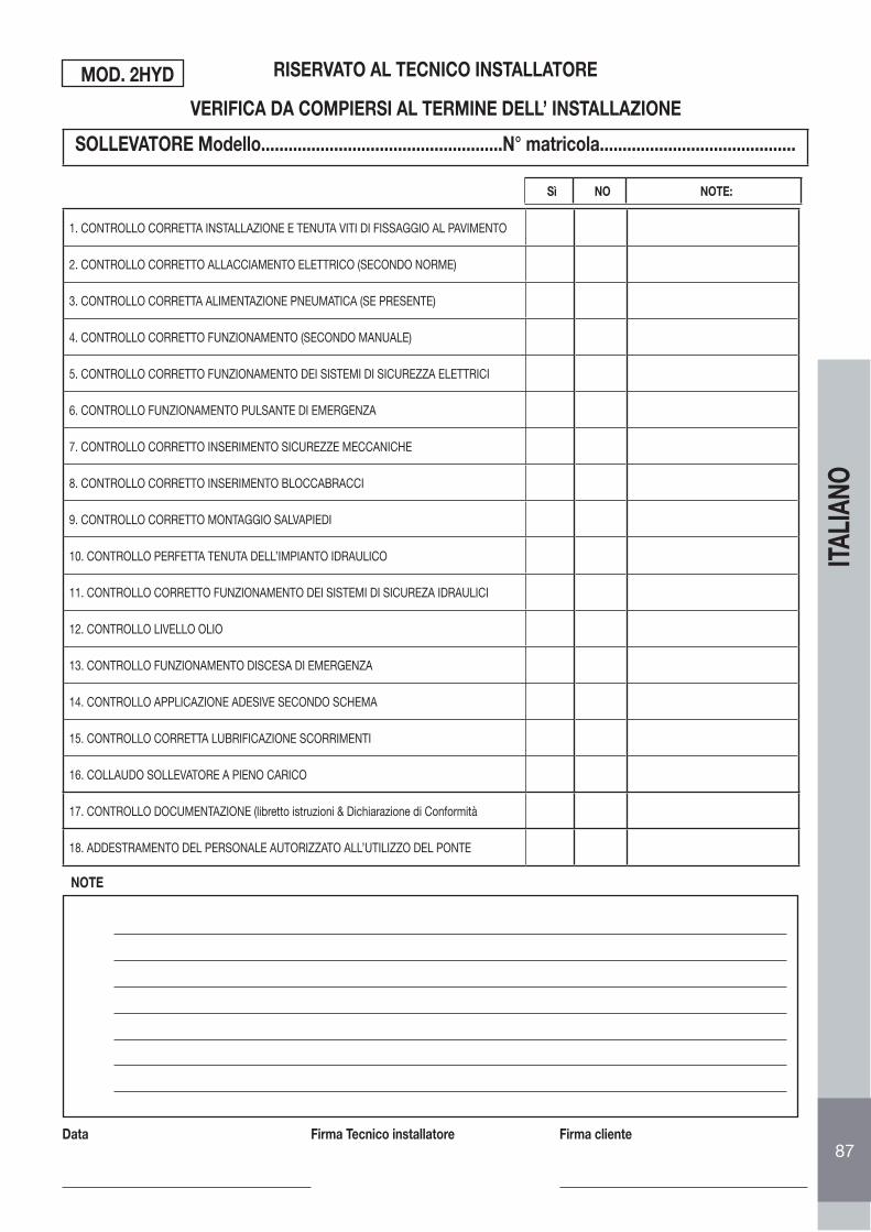
SOLLEVATORE Modello.....................................................N° matricola...........................................
1. CONTROLLO CORRETTA INSTALLAZIONE E TENUTA VITI DI FISSAGGIO AL PAVIMENTO
2. CONTROLLO CORRETTO ALLACCIAMENTO ELETTRICO (SECONDO NORME)
3. CONTROLLO CORRETTA ALIMENTAZIONE PNEUMATICA (SE PRESENTE)
4. CONTROLLO CORRETTO FUNZIONAMENTO (SECONDO MANUALE)
5. CONTROLLO CORRETTO FUNZIONAMENTO DEI SISTEMI DI SICUREZZA ELETTRICI
6. CONTROLLO FUNZIONAMENTO PULSANTE DI EMERGENZA
7. CONTROLLO CORRETTO INSERIMENTO SICUREZZE MECCANICHE
8. CONTROLLO CORRETTO INSERIMENTO BLOCCABRACCI
9. CONTROLLO CORRETTO MONTAGGIO SALVAPIEDI
10. CONTROLLO PERFETTA TENUTA DELL’IMPIANTO IDRAULICO
11. CONTROLLO CORRETTO FUNZIONAMENTO DEI SISTEMI DI SICUREZA IDRAULICI
12. CONTROLLO LIVELLO OLIO
13. CONTROLLO FUNZIONAMENTO DISCESA DI EMERGENZA
14. CONTROLLO APPLICAZIONE ADESIVE SECONDO SCHEMA
15. CONTROLLO CORRETTA LUBRIFICAZIONE SCORRIMENTI
16. COLLAUDO SOLLEVATORE A PIENO CARICO
17. CONTROLLO DOCUMENTAZIONE (libretto istruzioni & Dichiarazione di Conformità
18. ADDESTRAMENTO DEL PERSONALE AUTORIZZATO ALL’UTILIZZO DEL PONTE
RISERVATO AL TECNICO INSTALLATORE
VERIFICA DA COMPIERSI AL TERMINE DELL’ INSTALLAZIONE
NOTE
Data Firma Tecnico installatore Firma cliente
MOD. 2HYD
Sì NO NOTE:
87
ITAL
IANO
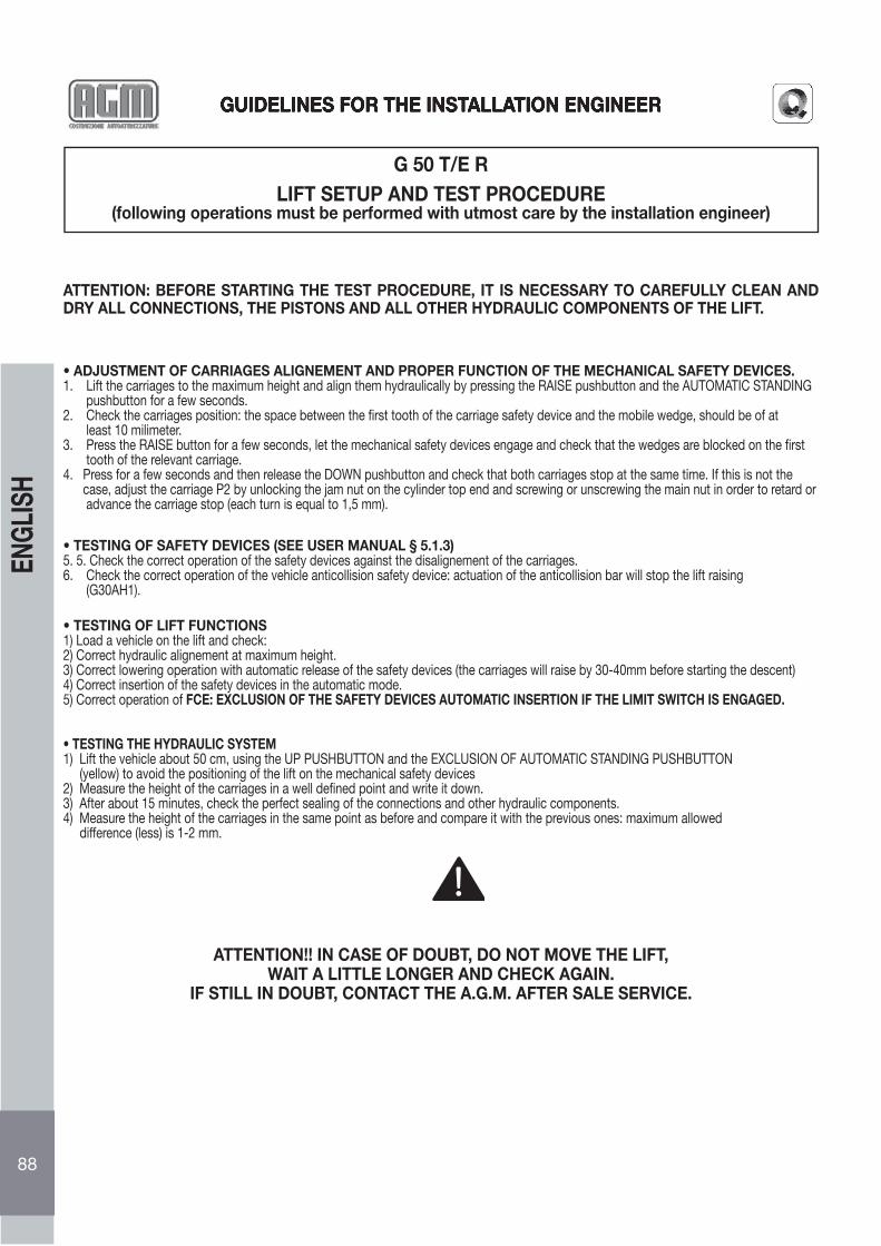
GUIDELINES FOR THE INSTALLATION ENGINEER
G 50 T/E RLIFT SETUP AND TEST PROCEDURE
(following operations must be performed with utmost care by the installation engineer)
ATTENTION: BEFORE STARTING THE TEST PROCEDURE, IT IS NECESSARY TO CAREFULLY CLEAN AND DRY ALL CONNECTIONS, THE PISTONS AND ALL OTHER HYDRAULIC COMPONENTS OF THE LIFT.
• ADJUSTMENT OF CARRIAGES ALIGNEMENT AND PROPER FUNCTION OF THE MECHANICAL SAFETY DEVICES.1. Lift the carriages to the maximum height and align them hydraulically by pressing the RAISE pushbutton and the AUTOMATIC STANDING pushbutton for a few seconds.2. Check the carriages position: the space between the fi rst tooth of the carriage safety device and the mobile wedge, should be of at least 10 milimeter.3. Press the RAISE button for a few seconds, let the mechanical safety devices engage and check that the wedges are blocked on the fi rst tooth of the relevant carriage.4. Press for a few seconds and then release the DOWN pushbutton and check that both carriages stop at the same time. If this is not the case, adjust the carriage P2 by unlocking the jam nut on the cylinder top end and screwing or unscrewing the main nut in order to retard or advance the carriage stop (each turn is equal to 1,5 mm).
• TESTING OF SAFETY DEVICES (SEE USER MANUAL § 5.1.3)5. 5. Check the correct operation of the safety devices against the disalignement of the carriages.6. Check the correct operation of the vehicle anticollision safety device: actuation of the anticollision bar will stop the lift raising (G30AH1).
• TESTING OF LIFT FUNCTIONS1) Load a vehicle on the lift and check:2) Correct hydraulic alignement at maximum height.3) Correct lowering operation with automatic release of the safety devices (the carriages will raise by 30-40mm before starting the descent)4) Correct insertion of the safety devices in the automatic mode.5) Correct operation of FCE: EXCLUSION OF THE SAFETY DEVICES AUTOMATIC INSERTION IF THE LIMIT SWITCH IS ENGAGED.
• TESTING THE HYDRAULIC SYSTEM1) Lift the vehicle about 50 cm, using the UP PUSHBUTTON and the EXCLUSION OF AUTOMATIC STANDING PUSHBUTTON (yellow) to avoid the positioning of the lift on the mechanical safety devices2) Measure the height of the carriages in a well defi ned point and write it down.3) After about 15 minutes, check the perfect sealing of the connections and other hydraulic components.4) Measure the height of the carriages in the same point as before and compare it with the previous ones: maximum allowed difference (less) is 1-2 mm.
ATTENTION!! IN CASE OF DOUBT, DO NOT MOVE THE LIFT,WAIT A LITTLE LONGER AND CHECK AGAIN.
IF STILL IN DOUBT, CONTACT THE A.G.M. AFTER SALE SERVICE.
GUIDELINES FOR THE INSTALLATION ENGINEER
88
ENGL
ISH

LIFT Type............................................................................Serial number...........................................
1. CHECK THAT INSTALLATION AND TIGHTNESS OF FLOOR ANCHORS ARE CORRECT
2. CHECK THAT ELECTRICAL CONNECTION IS IN COMPLIANCE TO THE NORMS
3. CHECK THAT THE PNEUMATIC SUPPLY IS CORRECT (IF INSTALLED)
4. CHECK THAT THE LIFT OPERATION IS CORRECT ACCORDING TO USER MANUAL
5. CHECK THE CORRECT FUNCTION OF THE ELECTRICAL SAFETY DEVICES
6. CHECK THE EMERGENCY BUTTON OPERATION
7. CHECK THE CORRECT INSERTING OF THE MECHANICAL SAFETY DEVICES
8. CHECK THE CORRECT INSERTING OF THE ARMS LOCKING DEVICES
9. CHECK THE CORRECT ASSEMBLING OF THE ANTI-TOE TRAPPING DEVI
10. CHECK THE PERFECT SEALING OF THE HYDRAULIC SYSTEM
11. CHECK THE CORRECT FUNCTION OF THE HYDRAULIC SAFETY DEVICES
12. CHECK THE OIL LEVEL
13. CHECK THE EMERGENCY LOWERING OPERATION
14. CHECK THE APPLICATION OF THE WARNING LABELS, AS PER LAYOUT
15. CHECK THE CORRECT LUBRICATION OF GUIDES
16. LIFT TESTING WITH MAXIMUM LOAD
17. CHECK DOCUMENTATION (user manual & declaration of conformity)
18. TRAINING OF PERSONNEL QUALIFIED TO USE THE LIFT
GUIDELINES FOR THE INSTALLATION ENGINEER
CONTROLS TO BE CARRIED OUT AFTER INSTALLATION
NOTE
Date: User:
Stamp and Signature
Montagetechniker:
Stempel und Unterschrift
MOD. 2HYD
YES NO NOTE:
89
ENGL
ISH
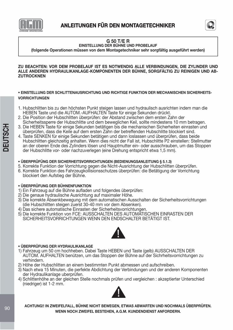
ANLEITUNGEN FÜR DEN MONTAGETECHNIKER
G 50 T/E REINSTELLUNG DER BÜHNE UND PROBELAUF
(folgende Operationen müssen von dem Montagetechniker sehr sorgfältig ausgeführt werden)
ZU BEACHTEN: VOR DEM PROBELAUF IST ES NOTWENDIG ALLE VERBINDUNGEN, DIE ZYLINDER UND ALLE ANDEREN HYDRAULIKANLAGE-KOMPONENTEN DER BÜHNE, SORGFÄLTIG ZU REINIGEN UND AB-ZUTROCKNEN
• EINSTELLUNG DER SCHLITTENAUSRICHTUNG UND RICHTIGE FUNKTION DER MECHANISCHEN SICHERHEITS-VORRICHTUNGEN
1. Hubschlitten bis zu den höchsten Punkt steigen lassen und hydraulisch ausrichten indem man die HEBEN Taste und die AUTOM.-AUFHALTEN Taste für einige Sekunden drückt.2. Die Position der Hubschlitten überprüfen: der Abstand zwischen dem ersten Zahn der Sicherheitssperre der Hubschlitte und dem beweglichen Keil, sollte mindestens 10 mm betragen.3. Die HEBEN Taste für einige Sekunden betätigen bis die mechanischen Sicherheiten einrasten und überprüfen, dass die Keile auf dem ersten Zahn der betreffenden Hubschlitte blockiert sind.4. Taste SENKEN für einige Sekunden betätigen und dann loslassen und überprüfen, dass beide Hubschlitten gleichzeitig anhalten. Wenn dies nicht der Fall ist, Hubschlitte P2 einstellen: Stellmutter an der oberen Ende des Zylinders lösen und Hauptmutter ein- oder ausschrauben, um das Stoppen der Hubschlitte vor- oder nachzuverlegen (eine Drehung entspricht etwa 1,5 mm).
• ÜBERPRÜFÜNG DER SICHERHEITSVORRICHTUNGEN (BEDIENUNGSANLEITUNG § 5.1.3)5. Korrekte Funktion der Vorrichtung gegen die Nicht-Ausrichtung der Hubschlitten überprüfen.6. Korrekte Funktion des Fahrzeugkollisionsschutzes überprüfen: die Betätigung der Vorrichtung blockiert den Aufstieg der Bühne.
• ÜBERPRÜFUNG DER BÜHNENFUNKTION1) Ein Fahrzeug auf die Bühne aufl aden und folgendes überprüfen:2) Die genaue hydraulische Ausrichtung auf maximaler Höhe.3) Die korrekte Absenkbewegung mit dem automatischen Ausschalten der Sicherheitsvorrichtungen (die Hubschlitten steigen zuerst 30-40 mm vor dem Absenken).4) Das sichere automatische Einrasten der Sicherheitsvorrichtungen.5) Die korrekte Funktion von FCE: AUSSCHALTEN DES AUTOMATISCHEN EINRASTEN DER SICHERHEITSVORRICHTUNGEN WENN DEN ENDSCHALTER BETÄTIGT IST.
• ÜBERPRÜFUNG DER HYDRAULIKANLAGE1) Fahrzeug um 50 cm hochheben. Dabei Taste HEBEN und Taste (gelb) AUSSCHALTEN DER AUTOM. AUFHALTEN benützen, um das Stoppen der Bühne auf der Sichrheitsvorrichtungen zu verhindern.2) Höhe der Hubschlitten an einem bestimmten Punkt abmessen und aufschreiben.3) Nach etwa 15 Minuten, die perfekte Abdichtung der Verbindungen und der anderen Komponenten der Hydraulikanlage uberprüfen.4) Schlittenhöhe an der gleichen Stelle nochmals prüfen und vergleichen : akzeptierter Unterschied (niedriger) ist 1-2 mm.
ACHTUNG!! IN ZWEIFELFALL, BÜHNE NICHT BEWEGEN, ETWAS ABWARTEN UND NOCHMALS ÜBERPRÜFEN.WENN NOCH ZWEIFEL BESTEHEN, A.G.M. KUNDENDIENST ANFORDERN.
ANLEITUNGEN FÜR DEN MONTAGETECHNIKER
90
DEUT
SCH
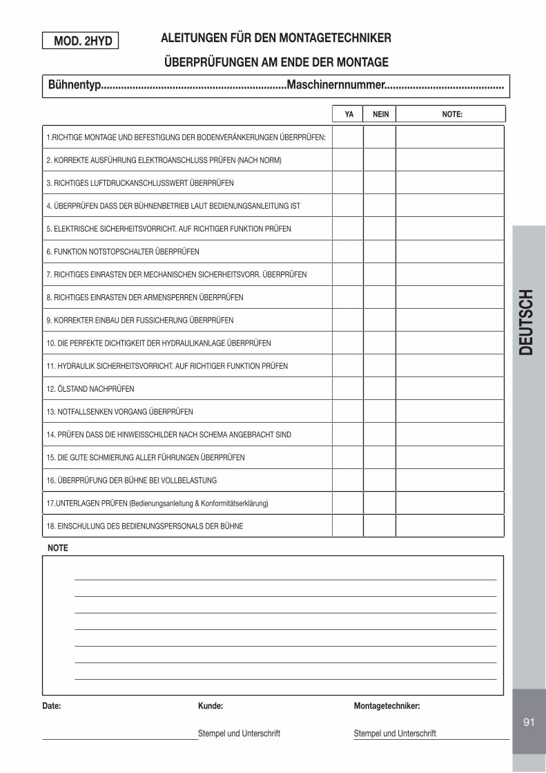
Bühnentyp.................................................................Maschinernnummer..........................................
1.RICHTIGE MONTAGE UND BEFESTIGUNG DER BODENVERÄNKERUNGEN ÜBERPRÜFEN:
2. KORREKTE AUSFÜHRUNG ELEKTROANSCHLUSS PRÜFEN (NACH NORM)
3. RICHTIGES LUFTDRUCKANSCHLUSSWERT ÜBERPRÜFEN
4. ÜBERPRÜFEN DASS DER BÜHNENBETRIEB LAUT BEDIENUNGSANLEITUNG IST
5. ELEKTRISCHE SICHERHEITSVORRICHT. AUF RICHTIGER FUNKTION PRÜFEN
6. FUNKTION NOTSTOPSCHALTER ÜBERPRÜFEN
7. RICHTIGES EINRASTEN DER MECHANISCHEN SICHERHEITSVORR. ÜBERPRÜFEN
8. RICHTIGES EINRASTEN DER ARMENSPERREN ÜBERPRÜFEN
9. KORREKTER EINBAU DER FUSSICHERUNG ÜBERPRÜFEN
10. DIE PERFEKTE DICHTIGKEIT DER HYDRAULIKANLAGE ÜBERPRÜFEN
11. HYDRAULIK SICHERHEITSVORRICHT. AUF RICHTIGER FUNKTION PRÜFEN
12. ÖLSTAND NACHPRÜFEN
13. NOTFALLSENKEN VORGANG ÜBERPRÜFEN
14. PRÜFEN DASS DIE HINWEISSCHILDER NACH SCHEMA ANGEBRACHT SIND
15. DIE GUTE SCHMIERUNG ALLER FÜHRUNGEN ÜBERPRÜFEN
16. ÜBERPRÜFUNG DER BÜHNE BEI VOLLBELASTUNG
17.UNTERLAGEN PRÜFEN (Bedienungsanleitung & Konformitätserklärung)
18. EINSCHULUNG DES BEDIENUNGSPERSONALS DER BÜHNE
ALEITUNGEN FÜR DEN MONTAGETECHNIKER
ÜBERPRÜFUNGEN AM ENDE DER MONTAGE
NOTE
Date: Kunde:
Stempel und Unterschrift
Montagetechniker:
Stempel und Unterschrift
MOD. 2HYD
YA NEIN NOTE:
91
DEUT
SCH
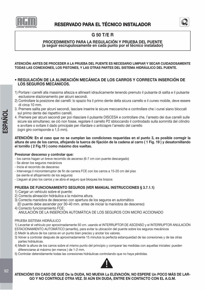
RESERVADO PARA EL TÉCNICO INSTALADOR
G 50 T/E RPROCEDIMIENTO PARA LA REGULACIÓN Y PRUEBA DEL PUENTE(a seguir escrupulosamente en cada punto por el técnico instalador)
ATENCIÓN: ANTES DE PROCEDER A LA PRUEBA DEL PUENTE ES NECESARIO LIMPIAR Y SECAR CUIDADOSAMENTE TODAS LAS CONEXIONES, LOS PISTONES, Y LAS OTRAS PARTES DEL SISTEMA HIDRÁULICO DEL PUENTE.
• REGULACIÓN DE LA ALINEACIÓN MECÁNICA DE LOS CARROS Y CORRECTA INSERCIÓN DE LOS SEGUROS MECÁNICOS.
1) Portare i carrelli alla massima altezza e allinearli idraulicamente tenendo premuto il pulsante di salita e il pulsante esclusione stazionamento per alcuni secondi.2) Controllare la posizione dei carrelli: lo spazio fra il primo dente della sicura carrello e il cuneo mobile, deve essere di circa 10 mm.3. Premere salita per alcuni secondi, lasciare inserire le sicure meccaniche e controllare che i cunei siano bloccati sul primo dente dei rispettivi carrelli.4. Premere per alcuni secondi per poi rilasciare il pulsante DISCESA e controllare che, l’arresto dei due carrelli sulle sicure sia simultaneo; se ciò non fosse, regolare il carrello P2 sbloccando il controdado sulla sommità del cilindro e avvitare o svitare il dado principale per ritardare o anticiapre l’arresto del carrello (ogni giro corrisponde a 1,5 mm).
ATENCIÓN: En el caso que no se cumplan las condiciones requeridas en el punto 3, es posible corregir la altura de uno de los carros, afl ojando la tuerca de fi jación de la cadena al carro ( 1 Fig. 19 ) y desatornillando el tornillo ( 2 Fig.19 ) como máximo dos vueltas.
Presionar descenso y controlar que:- Ios carros hagan un breve recorrido de ascenso (6-7 cm con puente descargado)- Se abran los seguros mecánicos- Inicie el recorrido de descenso- Intervenga il microinterruptor de fi n de carrera FCE con los carros a 15-20 cm del piso (se siente el afl ojamiento de los seguros)- Lleguen al piso los carros y se abra el seguro que bloquea los brazos
PRUEBA DE FUNCIONAMIENTO SEGUROS (VER MANUAL INSTRUCCIONES § 3.7.1.1)1) Cargar un vehículo sobre el puente:2) Correcta alineación hidráulica a la máxima altura.3) Correcta maniobra de descenso con apertura de los seguros en automático (El puente debe ascender por 30-40 mm. antes de iniciar la maniobra de descenso)4) Correcto funcionamiento FCE: ANULACIÓN DE LA INSERCIÓN AUTOMÁTICA DE LOS SEGUROS CON MICRO ACCIONADO
PRUEBA SISTEMA HIDRÁULICO1) Levantar el vehículo por aproximadamente 50 cm. usando el INTERRUPTOR DE ASCENSO y el INTERRUPTOR ANULACIÓN ESTACIONAMIENTO AUTOMÁTICO (amarillo), para evitar la ubicación del puente sobre los seguros mecánicos2) Medir la altura de los carros en un punto bien preciso y anotar los valores.3) Volver a controlar después de aproximadamente 15 minutos la perfecta estanqueidad de las conexiones y de las otras partes hidráulicas.4) Medir la altura de los carros sobre el mismo punto del principio y comparar las medidas con aquellas iniciales: pueden diferenciarse al máximo (en menos ) de 1-2 mm.5) Controlar detenidamente todas las conexiones hidráulicas controlando que no haya pérdidas.
ATENCIÓN!! EN CASO DE QUE De la DUDA, NO MUEVA La ELEVACIÓN, NO ESPERE Un POCO MÁS DE LAR-GO Y NO CONTROLE OTRA VEZ. SI AÚN EN DUDA, ENTRE EN CONTACTO CON EL A.G.M.
RESERVADO PARA EL TÉCNICO INSTALADOR
92
ESPA
ÑOL
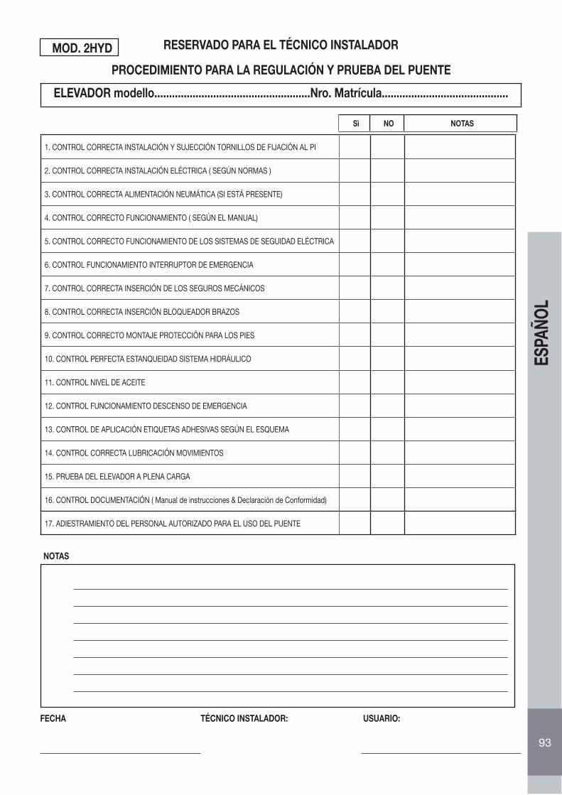
ELEVADOR modello.....................................................Nro. Matrícula...........................................
1. CONTROL CORRECTA INSTALACIÓN Y SUJECCIÓN TORNILLOS DE FIJACIÓN AL PI
2. CONTROL CORRECTA INSTALACIÓN ELÉCTRICA ( SEGÚN NORMAS )
3. CONTROL CORRECTA ALIMENTACIÓN NEUMÁTICA (SI ESTÁ PRESENTE)
4. CONTROL CORRECTO FUNCIONAMIENTO ( SEGÚN EL MANUAL)
5. CONTROL CORRECTO FUNCIONAMIENTO DE LOS SISTEMAS DE SEGUIDAD ELÉCTRICA
6. CONTROL FUNCIONAMIENTO INTERRUPTOR DE EMERGENCIA
7. CONTROL CORRECTA INSERCIÓN DE LOS SEGUROS MECÁNICOS
8. CONTROL CORRECTA INSERCIÓN BLOQUEADOR BRAZOS
9. CONTROL CORRECTO MONTAJE PROTECCIÓN PARA LOS PIES
10. CONTROL PERFECTA ESTANQUEIDAD SISTEMA HIDRÁULICO
11. CONTROL NIVEL DE ACEITE
12. CONTROL FUNCIONAMIENTO DESCENSO DE EMERGENCIA
13. CONTROL DE APLICACIÓN ETIQUETAS ADHESIVAS SEGÚN EL ESQUEMA
14. CONTROL CORRECTA LUBRICACIÓN MOVIMIENTOS
15. PRUEBA DEL ELEVADOR A PLENA CARGA
16. CONTROL DOCUMENTACIÓN ( Manual de instrucciones & Declaración de Conformidad)
17. ADIESTRAMIENTO DEL PERSONAL AUTORIZADO PARA EL USO DEL PUENTE
RESERVADO PARA EL TÉCNICO INSTALADOR
PROCEDIMIENTO PARA LA REGULACIÓN Y PRUEBA DEL PUENTE
NOTAS
FECHA TÉCNICO INSTALADOR: USUARIO:
MOD. 2HYD
Sì NO NOTAS
93
ESPA
ÑOL

AGM-COS.MET - srlSede legale: Via Casette, 3/B • Fraz. Almisano - 36045 LONIGO (Vicenza) Italy
Destinazione merce e corrispondenza: Via Casette, 3/B • Fraz. Almisano - 36045 LONIGO (Vicenza) ItalyTel. ++39 0444 720622 • Fax ++39 0444 720623
http: //www.agm-cosmet.come-mail: [email protected]
www.stargraphic.itED.04/07


![iJLO-G50 gebruiksaanwijzing[1]](https://img.pdfslide.tips/doc/110x75/547edf24b379594e2b8b5582/ijlo-g50-gebruiksaanwijzing1.jpg)