Embed Size (px)
Citation preview

Cylinder stroke (mm)
NilSn
Number of auto switches
2 pcs.1 pc.n pcs.
Solid state switch
Type of auto switchM9B, M9BW
Reed switch A93
Air Cylinderø20, ø25, ø32, ø40
How to Order
21 - C D M 2 L 40 - 150 A Z - M9BW
10 - C D M 2 L 40 - 150 A F Z - M9BW
Bore size (mm)
∗ Rubber bumper only
NilF
Male rod endFemale rod end
Rod end thread
10-/11-21-/22-Series CM2-Z
1011
Relief typeVacuum suction type
Clean series
Nil
Built-in magnetNo
D With auto switch(Built-in magnet)
BLFGBZFZ
Mounting styleBasic style (Double-side bossed)
Axial foot styleRod side flange style
Head side flange styleBoss-cut basic style
Boss-cut rod side flange style
NilTNTF
Port thread typeRc
NPT∗
G∗2122
Relief typeVacuum suction type
Copper, fluorine andsilicone-free +Low particle generation Nil
A
CushionRubber bumper
Air cushion
Model
10-/21-CM22010-/21-CM22510-/21-CM23210-/21-CM24011-/22-CM22011-/22-CM22511-/22-CM23211-/22-CM240
Rel
ief
type
Vac
uum
suct
ion
type
Bore size(mm)
2025324020253240
Port size
1/8
1/4
1/4
Lubrication
Non-lubeDouble acting,
Single rod
Action Standard stroke(mm)
25, 50, 75, 100, 125,
150, 200, 250, 300
Auto switchmounting
CushionRubber Air
1/8
Model
Proof pressureMaximum operating pressureMinimum operating pressure
Ambient and fluid temperature
Piston speedStroke length toleranceMounting style
Grease
Particle generation grade (Refer to front matter 13 for details.)
20/25/32/40
1.5 MPa1.0 MPa0.05 MPa
Without auto switch: –10°C to 70°CWith auto switch: –10°C to 60°C (No freezing)
+1.4
Basic style/Axial foot style/Rod side flange style/Head side flange style0
Bore size (mm)Item
10-/11-: 30 to 400 mm/s, 21-/22-: 50 to 400 mm/s
Specifications
10-/11-: Fluorine grease21-/22-: Lithium soap based grease
10-: Grade 2, 21-: Grade 311-/22-: Grade 1
2Bore size Suction flow rate L/min (ANR)
20/25/32/40
Suction flow rate of vacuum suction type (Reference values)
14A

Note 1) Lead wire length symbols: 0.5 m………Nil M9BW 1 m……… M M9BWM 3 m……… L M9BWL 5 m……… Z M9BWZ
Note 2) Auto switches marked with “” are produced upon receipt of order.Note 3) PLC: Programmable Logic Controller
Applicable loadLead wire length (m)
Relay,PLC
TypeLoad voltageWiring
(Output) 3 (L)1 (M)0.5 (Nil)Auto switch model
Band mountingDC AC
12 V24 V2-wire
Indicatorlight
Yes
Electricalentry
GrommetReed auto switch
5 (Z)
M9B
M9BW—5 V
12 V24 V2-wireYesGrommetSolid stateauto switch
——
A93100 V
Auto Switch Specifications (Refer to Best Pneumatics No. 2 for detailed specifications and auto switches not in the following table.)
Auto Switches/Proper Mounting Position at Stroke End Detection
Note) The above-mentioned value is a guide for auto switch mounting position for stroke end detection. When actually mounting the auto switch, adjust the position after confirming the operating state of the auto switch.
D-M9D-M9W
A and B are the dimensions from the end of the head cover/rod cover to the end of the auto switch.
A and B are the dimensions from the end of the head cover/rod cover to the end of the auto switch.
D-A9Reed auto switchSolid state auto switch
A
A≈Hs
22 B
≈Hs
16
24.5 B
16
Auto Switch Mounting HeightAuto switch
model
Bore size
20253240
Hs22.5
25
28.5
32.5
D-M9D-M9WD-A9
(mm)
Auto Switch Proper Mounting PositionAuto switch
model
Bore size A11
10
11.5
17.5
B 9.5
10
10.5
15.5
D-A9D-M9D-M9W
A 7
6
7.5
13.5
B 5.5
6
6.5
11.5
(mm)
20253240
Refer to page 182 for a list of applicable auto switches.
Air
cylin
der
Rot
ary
actu
ator
Air
grip
per
Dire
ctio
nal c
ontr
olva
lve
Fitt
ings
& T
ubin
gP
ress
ure
switc
hC
lean
gas
filte
rF
low
con
trol
equi
pmen
tF
ilter
, Pre
ssur
eco
ntro
l equ
ipm
ent
Air
prep
arat
ion
equi
pmen
t
15
Air Cylinder CM2-Z21-22-CM2-Z/10-
11-
B

With rubber bumper
20253240
Bore size
8 81213
A1
20202021
HM4 x 0.7M5 x 0.8M6 x 1
M8 x 1.25
MM 95 95 97125
ZZ(mm)Female Rod End
∗ When female thread is used, use a thin wrench when tightening the piston rod.
∗ When female thread is used, use a wash-er etc. to prevent the contact part at the rod end from being deformed depending on the material of the workpiece.
(mm)ZZSPIEDA
40322520
24222218
2119.519.515.5
1412108 20-0.033
46.537.533.528
75.55.55
M14 x 1.5M10 x 1.25M10 x 1.25M8 x 1.25
42.534.53024
M26 x 1.5M26 x 1.5M20 x 1.5
1/41/81/8
88646262
1541221201161/8
M32 x 2
0
26-0.0330
26-0.0330
32-0.0390
AL K
121086
KA MM NA NNG
161313
1188813
F
13.510.510.510.5FLBore size H2
888
10
H1
665
8
H
50454541
22171713B1
41323226B2
ø20, ø25
ø32, ø40
2 x
øE
h8
2 x NNG
M5 x 0.8(This drawing shows the cases of ø20 and ø25.)Relief port (10-, 21-)Vacuum port (11-, 22-)
2 x P(Rc, NPT, G)
GH2
Width across flats KA
øD
ZZ + Stroke
S + StrokeHF
1.5
FEffective thread length2 x FL
1.5
AAL
K
Standard port
Standard port
NA
NA
øI
45°
Female rod end
ZZ + StrokeH
3.5
Thread depth A1
Female thread MM
Relief port (10-, 21-)Vacuum port (11-, 22-)
H1Width across flats B1
Width across flats B2
MM
Relief port (10-, 21-)Vacuum port (11-, 22-)
Basic style (Double-side bossed) (B) / CM2B, CM2B10-11-
21-22-
16
Air Cylinder CM2-Z21-22-CM2-Z/10-
11-
A


(mm)
20253240
Bore size
8 81213
A1
20202021
HM4 x 0.7M5 x 0.8M6 x 1
M8 x 1.25
MM113113115145
ZZ(mm)Female Rod End
WB13131316
WA31313136
26262631
GA888
11
GB68
1012
KAFL10.510.510.513.5
134138140174
41454550
888
10
5668
26323241
13171722
ZZH H2H1B2B1
808082
108
S1/81/81/81/4
PM20 x 1.5M26 x 1.5M26 x 1.5M32 x 2
NN2430
34.542.5
NAM8 x 1.25M10 x 1.25M10 x 1.25M14 x 1.5
MM5
5.55.57
K28
33.537.546.5
I6666
GC13131316
F0 20−0.0330 26−0.0330 26−0.0330 32−0.039
E8
101214
D15.519.519.521
AL18222224
A20253240
Bore size
ZZ + Stroke
S + Stroke F
1.5
Effective thread length2 x FL
1.5
HFA
ALKMM
øD
GCH2 GA
WA
Width across flats B1
H1
Width across flats KAWidth across flats B2
M5 x 0.8Relief port (10-, 21-)Vacuum port (11-, 22-)
2 x
øE
h8
2 x NNGBWB
NA
NA
Cushion needle(Width across flats 1.5)
45°
øI
2 x P(Rc)
Female rod end
H3.5
Thread depth A1
Female thread MM
ZZ + Stroke
With air cushion
Basic style (Double-side bossed) (B) / CM2B, CM2B10-11-
21-22-
∗ When female thread is used, use a thin wrench when tightening the piston rod.
∗ When female thread is used, use a wash-er etc. to prevent the contact part at the rod end from being deformed depending on the material of the workpiece.
16-1
Air Cylinder CM2-Z21-22-CM2-Z/10-
11-
A
With air cushion
(mm)WB13131316
WA31313136
26262631
GA888
11
GB68
1012
KAFL10.510.510.513.5
121125127158
41454550
888
10
5668
26323241
13171722
ZZH H2H1B2B1
808082
108
S1/81/81/81/4
PM20 x 1.5M26 x 1.5M26 x 1.5M32 x 2
NN2430
34.542.5
NAM8 x 1.25M10 x 1.25M10 x 1.25M14 x 1.5
MM5
5.55.57
K28
33.537.546.5
I6666
GC13131316
F0 20−0.0330 26−0.0330 26−0.0330 32−0.039
E8
101214
D15.519.519.521
AL18222224
A20253240
Bore size
ZZ + Stroke
S + Stroke
1.5
HFA
ALKMM
øD
GCH2 GA
WA
H1
GBWB
NA
NA
Cushion needle(Width across flats 1.5)
45°
øI
2 x P(Rc)
øE
h8
NN
M5 x 0.8Relief port (10-, 21-)Vacuum port (11-, 22-)
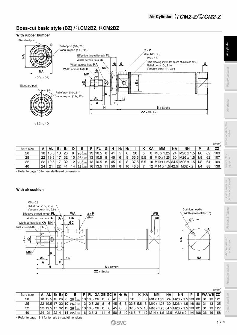
∗ Refer to page 16 for female thread dimensions.
∗ Refer to page 16-1 for female thread dimensions.
(mm)ZZH H2H1 SPIGE�DA
40322520
24222218
2119.519.515.5
1412108 20-0.033
161313
1188
46.537.533.528
75.55.55
M14 x 1.5M10 x 1.25M10 x 1.25M8 x 1.25
42.534.53024
M26 x 1.5M26 x 1.5M20 x 1.5
1/41/81/8
88646262
22171713
41323226
665
888
50454541
138109107103
108
1/8
M32 x 2
8130
26-0.0330
26-0.0330
32-0.0390
AL F
13.510.510.510.5FL K
121086
KA MM NA NNB1 B2Bore size
ø20, ø25
ø32, ø40
Width across flats KA G
2 x P(Rc, NPT, G)
M5 x 0.8(This drawing shows the cases of ø20 and ø25.)Relief port (10-, 21-)Vacuum port (11-, 22-)
Effective thread length FL
GH2
NN
Width across flats B2
H1
MM
Width across flats B1
øD
ZZ + Stroke
S + StrokeHF
1.5
AAL
K
øE
h8
Standard port
Standard port
NA
NA
øI
45°
Relief port (10-, 21-)Vacuum port (11-, 22-)
Relief port (10-, 21-)Vacuum port (11-, 22-)
With rubber bumper
Boss-cut basic style (BZ) / CM2BZ, CM2BZ10-11-
21-22-
Width across flats KA
Effective thread length FLWidth across flats B2
Width across flats B1A
ir cy
linde
rR
otar
y ac
tuat
orA
ir gr
ippe
rD
irect
iona
l con
trol
valv
eF
ittin
gs &
Tub
ing
Pre
ssur
e sw
itch
Cle
an g
as fi
lter
Flo
w c
ontr
oleq
uipm
ent
Filt
er, P
ress
ure
cont
rol e
quip
men
tA
ir pr
epar
atio
neq
uipm
ent
17
Air Cylinder CM2-Z21-22-CM2-Z/10-
11-
A

With air cushion
ø20, ø25
ø32, ø40
(mm)
40474754
B120120122154
21252527
Z888
10
Y20202023
X55555575
LZ40404055
LX3.23.23.23.2
LTLS25282830
LH6.86.86.87
LD4444
LC WB13131316
WA31313136
26262631
GA888
11
GB68
1012
KAFL10.510.510.513.5
149153155191
41454550
888
10
5668
26323241
13171722
ZZH H2H1B2B1
808082
108
S1/81/81/81/4
PM20 x 1.5M26 x 1.5M26 x 1.5M32 x 2
NN2430
34.542.5
NAM8 x 1.25M10 x 1.25M10 x 1.25M14 x 1.5
MM5
5.55.57
K28
33.537.546.5
I6666
GC13131316
F8101214
D15.519.519.521
AL18222224
A20253240
Bore size
45°
Cushion needle(Width across flats 1.5)
BL
H
LZLX
2 x øLC
LTYX
øI
FGB
WB2 x P(Rc)
M5 x 0.8Relief port (10-, 21-)Vacuum port (11-, 22-)
GCGAWA
FH
H2
KMM
øD
H1
ALA
Width across flats B2 Width across flats NA
Width across flats KA
Width across flats B1
ZY X
ZZ + Stroke
LS + Stroke
S + Stroke
4 x øLD
(mm)H H2H1 SPIGDA
40322520
24222218
2119.519.515.5
1412108
161313
1188
46.537.533.528
75.55.55
M14 x 1.5M10 x 1.25M10 x 1.25M8 x 1.25
42.534.53024
M26 x 1.5M26 x 1.5M20 x 1.5
1/41/81/8
88646262
22171713
41323226
665
888
50454541
108
1/8
M32 x 2
813AL F
13.510.510.510.5FL K
121086
KA MM NA NNB1 B2Bore size
54474740B LH LTLS LXLD
444
76.86.8
55404040
75555555
104102102
3.23.23.2
30282825
3.2134
6.84LC LZ X Y
10888
27252521
202020
23
Z ZZ
171137135131
∗ The bracket is shipped together. ∗ Refer to page 16 for female thread dimensions.
∗ The bracket is shipped together. ∗ Refer to page 16-1 for female thread dimensions.
ZZ + Stroke
LS + Stroke
S + Stroke X YXYZ
LT
Width across flats B2
øD
MM
Width across flats B1
HGF
H2
KH1
ALA
2 x P(Rc, NPT, G)
M5 x 0.8(This drawing shows the cases of ø20 and ø25.)Relief port (10-, 21-)Vacuum port (11-, 22-)
Width across flats NA
2 x NN(Effective thread length 2 x FL)
G F
øI
4 x øLD
BL
H
Standard port
Standard port
2 x øLCLZLX
45°
Width across flats KA
Relief port (10-, 21-)Vacuum port (11-, 22-)
Relief port (10-, 21-)Vacuum port (11-, 22-)
Axial foot style (L) / CM2L, CM2LWith rubber bumper
10-11-
21-22-
2 x NN(Effective thread length 2 x FL)
18
Air Cylinder CM2-Z21-22-CM2-Z/10-
11-
A

ø20 to ø32
ø40
With air cushion
(mm)
37414145
Z75757582
FZ———36
FY60606066
FX4445
FT7777
FD303737
47.3
C2
34404052
B WB13131316
WA31313136
26262631
GA888
11
GB68
1012
KAFL10.510.510.513.5
134138140174
41454550
888
10
5668
26323241
13171722
ZZH H2H1B2B1
808082
108
S1/81/81/81/4
PM20 x 1.5M26 x 1.5M26 x 1.5M32 x 2
NN2430
34.542.5
NAM8 x 1.25M10 x 1.25M10 x 1.25M14 x 1.5
MM5
5.55.57
K28
33.537.546.5
I6666
GC13131316
F 0 20−0.033 0 26−0.033 0 26−0.033 0 32−0.039
E8
101214
D15.519.519.521
AL18222224
A20253240
Bore size
C2
45°
45°
øI
2 x
øE
h8
WBGB
F1.5
2 x NN
ZZ + Stroke
S + Stroke
2 x P(Rc)
M5 x 0.8Relief port (10-, 21-)Vacuum port (11-, 22-)
WAGAGC
H2
H1
øD
HFTZ
KAAL
B
FZFX
2 x øFDMounting hole Cushion needle
(Width across flats 1.5)
Cushion needle(Width across flats 1.5)
FY
4 x øFDMounting hole
ø40
ø20 to ø32
MM
ZH H2H1 SPIFC2A
40322520
24222218
2119.519.515.5
47.3373730
141210
161313
46.537.533.528
FL
13.510.510.510.5
75.55.55
M14 x 1.5M10 x 1.25M10 x 1.25M8 x 1.25
42.534.53024
M26 x 1.5M26 x 1.5M20 x 1.5
1/41/81/8
88646262
22171713
41323226
665
888
50454541
45414137
108
1/8
M32 x 2
138AL D K
121086
KA MM NA NNB1 B2Bore size
52404034B FX FZFY GFT
777
544
11888
———
757575
66606060
8236
47FDE
20-0.0330
26-0.0330
26-0.0330
32-0.0390
ZZ
154122120116
(mm)
∗ The bracket is shipped together. ∗ Refer to page 16 for female thread dimensions.
∗ The bracket is shipped together. ∗ Refer to page 16-1 for female thread dimensions.
2 x NN
øI
øE
h8
G
ZZ + Stroke
S + Stroke
1.5
2 x P(Rc, NPT, G)
M5 x 0.8(This drawing shows the cases of ø20 and ø25.)Relief port (10-, 21-)Vacuum port(11-, 22-)
GH2
Width across flats B2
H1Width across flats B1
MM
øD
H
FTKAAL
Z
FZFX
B
Standard port2 x øFDRelief port (10-, 21-)Vacuum port (11-, 22-)(ø20, ø25)
Standard port 45°
FY
4 x øFD
F
C2
Width across flats KA
Width across flats NA
Effective thread length 2 x FL
Relief port (10-, 21-)Vacuum port (11-, 22-)(ø32,ø40)
Rod side flange style (F) / CM2F, CM2FWith rubber bumper
10-11-
21-22-
Width across flats B2
Width across flats B1
Width across flats KA
Width across flats NA
Effective thread length 2 x FL
Air
cylin
der
Rot
ary
actu
ator
Air
grip
per
Dire
ctio
nal c
ontr
olva
lve
Fitt
ings
& T
ubin
gP
ress
ure
switc
hC
lean
gas
filte
rF
low
con
trol
equi
pmen
tF
ilter
, Pre
ssur
eco
ntro
l equ
ipm
ent
Air
prep
arat
ion
equi
pmen
t
19
Air Cylinder CM2-Z21-22-CM2-Z/10-
11-
A

With air cushion
ø20 to ø32
ø40
(mm)
125129131163
Z75757582
FZ———36
FY60606066
FX4445
FT7777
FD303737
47.3
C2
34404052
B WB13131316
WA31313136
26262631
GA888
11
GB68
1012
KAFL10.510.510.513.5
134138140174
41454550
888
10
5668
26323241
13171722
ZZH H2H1B2B1
808082
108
S1/81/81/81/4
PM20 x 1.5M26 x 1.5M26 x 1.5M32 x 2
NN2430
34.542.5
NAM8 x 1.25M10 x 1.25M10 x 1.25M14 x 1.5
MM5
5.55.57
K28
33.537.546.5
I6666
GC13131316
F 0 20−0.033 0 26−0.033 0 26−0.033 0 32−0.039
E8
101214
D15.519.519.521
AL18222224
A20253240
Bore size
ZH H2H1 SPIFC2A
40322520
24222218
2119.519.515.5
47.3373730
141210
161313
46.537.533.528
FL
13.510.510.510.5
75.55.55
M14 x 1.5M10 x 1.25M10 x 1.25M8 x 1.25
42.534.53024
M26 x 1.5M26 x 1.5M20 x 1.5
1/41/81/8
88646262
22171713
41323226
665
888
50454541
143113111107
108
1/8
M32 x 2
138AL D K
121086
KA MM NA NNB1 B2Bore size
52404034B FX FZFY GFT
777
544
11888
———
757575
66606060
8236
47FDE
20-0.0330
26-0.0330
26-0.0330
32-0.0390
ZZ
154122120116
(mm)
øI
WBGB
Z + Stroke
ZZ + Stroke
S + Stroke
M5 x 0.8Relief port (10-, 21-)Vacuum port (11-, 22-)
WAGAGC
H2
H1
øD
HKA
AL
B
FZFX
FY
ø40
ø20 to ø32
FFT
2 x
øE
h8
1.5MM
45°
45°
C2
∗ The bracket is shipped together. ∗ Refer to page 16 for female thread dimensions.
∗ The bracket is shipped together. ∗ Refer to page 16-1 for female thread dimensions.
B
FZFXRelief port
(ø20, ø25)
øI
ZZ + Stroke
Z + Stroke
S + StrokeH
1.5
AAL
K
F
øD
øE
h8
G
H1
MM
2 x P(Rc, NPT, G)
FT
H2G
Relief port(ø32, ø40)
FY
45°
C2
With rubber bumper
Head side flange style (G) / CM2G, CM2G10-11-
21-22-
Width across flats NA
Width across flats NA
Effective thread length 2 x FL
Effective thread length 2 x FL
2 x NN
2 x NN
Standard port2 x øFD
Width across flats B1
Width across flats B1
Width across flats KA
Width across flats KA
Width across flats B2
Width across flats B2
Standard port
4 x øFD
Cushion needle(Width across flats 1.5)
Cushion needle(Width across flats 1.5)
M5 x 0.8(This drawing shows the cases of ø20 and ø25.)Relief port (10-, 21-)Vacuum port (11-, 22-)
2 x øFDMounting hole
2 x øFDMounting hole
2 x P(Rc)
20
Air Cylinder CM2-Z21-22-CM2-Z/10-
11-
A

Specific Product Precautions
Be sure to read before handling.
Operating Precautions
Warning1. Do not rotate the cover.
If a cover is rotated when installing a cylinder or screwing a fitting into the port, it is likely to damage the junction part with cover.
2. When female rod end is used, use a washer etc. to prevent the contact part at the rod end from being deformed depending on the material of the workpiece.
3. Do not apply excessive lateral load to the piston rod.Easy checking methodMinimum operating pressure after the cylinder is mounted to the equipment (MPa) = Minimum operating pressure of cylinder (MPa) + {Load mass (kg) x Friction coefficient of guide/Sectional area of cylinder (mm2)}If smooth operation is confirmed within the above value, the load on the cylinder is the resistance of the thrust only and it can be judged as having no lateral load.
1. Not able to disassemble.Cover and cylinder tube are connected to each other by caulking method, thus making it impossible to disassemble. Therefore, internal parts of a cylinder other than rod seal are not replaceable.
2. Use caution to the popping of a retaining ring.When replacing rod seals and removing and mounting a re-taining ring, use a proper tool (retaining ring plier: tool for in-stalling a type C retaining ring). Even if a proper tool is used, it is likely to inflict damage to a human body or peripheral equip-ment, as a retaining ring may be flown out of the tip of a plier. Be much careful with the popping of a retaining ring. Besides, be certain that a retaining ring is placed firmly into the groove of rod cover before supplying air at the time of installment.
3. Do not touch the cylinder during operation.Use caution when handling a cylinder, which is running at a high speed and a high frequency, because the surface of a cylinder tube could get so hot enough as to cause you get burned.
4. Do not use an air cylinder as an air-hydro cylinder.If it uses turbine oil in place of fluids for cylinder, it may result in oil leakage.
5. The oil stuck to the cylinder is grease.
6. The base oil of grease may seep out.The base oil of grease in the cylinder may seep out of the tube, cover, crimped part or rod bushing depending on the operating conditions (ambient temperature 40°C or more, pressurized condition, low frequency operation).
7. When rod end female thread is used, use a thin wrench when tightening the piston rod.
Caution
Air
cylin
der
Rot
ary
actu
ator
Air
grip
per
Dire
ctio
nal c
ontr
olva
lve
Fitt
ings
& T
ubin
gP
ress
ure
switc
hC
lean
gas
filte
rF
low
con
trol
equi
pmen
tF
ilter
, Pre
ssur
eco
ntro
l equ
ipm
ent
Air
prep
arat
ion
equi
pmen
t
21
Air Cylinder CM2-Z21-22-CM2-Z/10-
11-
A

Double Rod Cylinderø20, ø25, ø32, ø40
How to Order
Cylinder stroke (mm)
Bore size (mm)
NilF
Male rod endFemale rod end
Rod end thread
10 - C D M 2 W L 40 - 150 F Z - M9BW
21 - C D M 2 W L 40 - 150 F Z - M9BW
Series CM2W-Z10-/11-21-/22-
1011
Relief typeVacuum suction type
Clean series
2122
Relief typeVacuum suction type
Nil
Built-in magnetNo
D With auto switch(Built-in magnet)
Mounting styleBLF
Basic styleAxial foot styleFlange style
NilTNTF
Port thread typeRc
NPTG
NilSn
2 pcs.1 pc.n pcs.
Solid state switch
Type of auto switchM9B, M9BW
Reed switch A93
Model
10-/21-CM2W2010-/21-CM2W2510-/21-CM2W3210-/21-CM2W4011-/22-CM2W2011-/22-CM2W2511-/22-CM2W3211-/22-CM2W40
Bore size(mm)
2025324020253240
Port size
1/8
1/4
1/4
Lubrication
Non-lubeDouble acting,
Double rod
ActionStandard stroke
(mm)
25, 50, 75, 100, 125150, 200, 250, 300
Auto switch mountingCushion
Rubber Air
1/8
Model
Proof pressureMaximum operating pressureMinimum operating pressure
Ambient and fluid temperature
Piston speed
20/25/32/40
1.5 MPa1.0 MPa0.08 MPa
With auto switch: –10°C to 60°C (No freezing)
+1.40
Bore size (mm)Item
Specifications
Stroke length tolerance10-/11-: 30 to 400 mm/s, 21-/22-: 50 to 400 mm/s
Mounting style Basic style/Axial foot style/Flange style
10-/11-: Fluorine grease21-/22-: Lithium soap based grease
10-: Grade 2, 21-: Grade 311-/22-: Grade 1
Grease
Particle generation grade(Refer to front matter 13 for details.)
Without auto switch: –10°C to 70°C
2Bore size Suction flow rate L/min (ANR)
20/25/32/40
Suction Flow Rate of Vacuum Suction Type (Reference values)
—
Rel
ief
type
Vac
uum
suct
ion
type
Number of auto switches
Copper, fluorine andsilicone-free +Low particle generation
Auto SwitchAuto switch specifications and the proper mounting positions for stroke end detection are the same as those for double acting, single rod type.
Refer to page 182 for a list of applicable auto switches.
22B

Specific Product Precautions
Be sure to read before handling.
Operating Precautions
Warning1. Do not rotate the cover.
If a cover is rotated when installing a cylinder or screwing a fitting into the port, it is likely to damage the junction part with cover.
2. When female rod end is used, use a washer etc. to prevent the contact part at the rod end from being deformed depending on the material of the workpiece.
3. Do not apply excessive lateral load to the piston rod.Easy checking methodMinimum operating pressure after the cylinder is mounted to the equipment (MPa) = Minimum operating pressure of cylinder (MPa) + {Load mass (kg) x Friction coefficient of guide/Sectional area of cylinder (mm2)}If smooth operation is confirmed within the above value, the load on the cylinder is the resistance of the thrust only and it can be judged as having no lateral load.
1. Not able to disassemble.Cover and cylinder tube are connected to each other by caulking method, thus making it impossible to disassemble. Therefore, internal parts of a cylinder other than rod seal are not replaceable.
2. Use caution to the popping of a retaining ring.When replacing rod seals and removing and mounting a re-taining ring, use a proper tool (retaining ring plier: tool for in-stalling a type C retaining ring). Even if a proper tool is used, it is likely to inflict damage to a human body or peripheral equip-ment, as a retaining ring may be flown out of the tip of a plier. Be much careful with the popping of a retaining ring. Besides, be certain that a retaining ring is placed firmly into the groove of rod cover before supplying air at the time of installment.
3. Do not touch the cylinder during operation.Use caution when handling a cylinder, which is running at a high speed and a high frequency, because the surface of a cylinder tube could get so hot enough as to cause you get burned.
4. Do not use an air cylinder as an air-hydro cylinder.If it uses turbine oil in place of fluids for cylinder, it may result in oil leakage.
5. The oil stuck to the cylinder is grease.
6. The base oil of grease may seep out.The base oil of grease in the cylinder may seep out of the tube, cover, crimped part or rod bushing depending on the operating conditions (ambient temperature 40°C or more, pressurized condition, low frequency operation).
7. When rod end female thread is used, use a thin wrench when tightening the piston rod.
Caution
Air
cylin
der
Rot
ary
actu
ator
Air
grip
per
Dire
ctio
nal c
ontr
olva
lve
Fitt
ings
& T
ubin
gP
ress
ure
switc
hC
lean
gas
filte
rF
low
con
trol
equi
pmen
tF
ilter
, Pre
ssur
eco
ntro
l equ
ipm
ent
Air
prep
arat
ion
equi
pmen
t
23
Air Cylinder CM2W-Z21-22-CM2W-Z/10-
11-
A

G
11888
ZH H2 H1 SPIFA
24222218
2119.519.515.5
141210
161313
46.537.533.528
75.55.55
M14 x 1.5M10 x 1.25M10 x 1.25M8 x 1.25
42.534.53024
M26 x 1.5M26 x 1.5M20 x 1.5
1/41/81/8
88646262
22171713
41323226
665
888
50454541
27252521
108
1/8
M32 x 2
138AL
13.510.510.510.5FLD K
121086
KA MM NA NNB1 B2
40322520
Bore size
54474740B ZZ
188154152144
LX
55404040
LH
30282825
LT
3.23.23.2
3.2
LS
104102102
134
LD
76.86.86.8
4444
LC
75555555LZ X Y
10888
202020
23
(mm)
H
50454541
SPIGEA
40322520
24222218
2119.519.515.5
D
1412108 20-0.033
161313
1188
46.537.533.528
75.55.55
M14 x 1.5M10 x 1.25M10 x 1.25M8 x 1.25
42.534.53024
M26 x 1.5M26 x 1.5M20 x 1.5
1/41/81/8
88646262
1881541521441/8
M32 x 2
8130
26-0.0330
26-0.0330
32-0.0390
AL
13.510.510.510.5FLF K
121086
KA MM NA NN ZZBore size
22171713B1
41323226B2 H2
888
10
(mm)H1
665
8
∗ The bracket is shipped together. ∗ Refer to the basic style for female thread dimensions.
ø20, ø25
ø32, ø40
ø20, ø25
ø32, ø40
Effective thread length 2 x FL
Width across flats KA
Width across flats KA
45°45°
øD
MM
ZZ + 2 x Stroke
S + Stroke
F1.5
H + Stroke
AAL
K
2 x NN
G
2 x P(Rc, NPT, G)
2 x M5 x 0.8(This drawing shows the cases of ø20 and ø25.)Relief port (10-, 21-)Vacuum port (11-, 22-)
2 x M5 x 0.8(This drawing shows the cases of ø20 and ø25.)Relief port (10-, 21-)Vacuum port (11-, 22-)
GH2Width across flats B2
H1
MM
Width across flats B1
Width across flats B2
Width acrossflats B1
øD
NA
NA
45° 45°
HF
1.5
AAL
K
ZZ + 2 x Stroke
LS + Stroke
S + Stroke XZ + Stroke
4 x øLD
Y
MM
øD
ALA
2 x NN(Effective threadlength 2 x FL)
KH + Stroke
FG
øI
ZXY
LT
øD
KH1
ALA
HG
H2
F
BL
H
LZLX
2 x øLC
Width across flats NA
2 x P(Rc, NPT, G)
øI
MM
2 x
øE
h8
20253240
Bore size
8 81213
A1
20202021
HM4 x 0.7M5 x 0.8M6 x 1
M8 x 1.25
MM102102104130
ZZ(mm)Female Rod EndFemale rod end
Standard port
Standard port
Standard port
Standard port
H3.5
Female thread MMThread depth A1
ZZ + 2 x Stroke
2 x M5 x 0.8Relief port (10-)Vacuum port (11-)
Relief port (10-, 21-)Vacuum port (11-, 22-)
Relief port (10-, 21-)Vacuum port (11-, 22-)
Relief port (10-, 21-)Vacuum port (11-, 22-)
Relief port (10-, 21-)Vacuum port (11-, 22-)
∗ When female thread is used, use a thin wrench when tightening the piston rod.
∗ When female thread is used, use a wash-er etc. to prevent the contact part at the rod end from being deformed depending on the material of the workpiece.
Basic style (B) / CM2WB, CM2WB
Axial foot style (L) / CM2WL, CM2WL
10-11-
21-22-
10-11-
21-22-
24
Air Cylinder CM2W-Z21-22-CM2W-Z/10-
11-
A

A
24222218
C2
47.3373730
I
46.537.533.528
S
88646262
H
50454541
Z
45414137
H2
888
10
H1
665
8
P
1/41/81/81/8
F
16131313
2119.519.515.5AL
13.510.510.510.5FL
1412108D
75.55.55K
121086
KA
M14 x 1.5M10 x 1.25M10 x 1.25M8 x 1.25
MM
42.534.53024NA
M26 x 1.5M26 x 1.5M20 x 1.5
M32 x 2
NN
22171713B1
41323226B2
40322520
Bore size
52404034B E
20-0.0330
26-0.0330
26-0.0330
32-0.0390
ZZ
188154152144
G
11888
FX
66606060
FZ
757575
82
FY
———
36
FT
5444
7777
FD(mm)
∗ The bracket is shipped together. ∗ Refer to page 24 for female thread dimensions.
ø20 to ø32
ø40
MM
GGH2
H1
MM
ZZ + 2 x Stroke
S + StrokeH H + Stroke
F K AAL1.5
Effective thread length2 x FL
øDøI
øEh8
KAAL
Z
FT
øDFZ
FX
BF
Y
2 x øFD Standard port
45°45°
Standard port
4 x øFD
C2
Relief port (10-, 21-)Vacuum port (11-, 22-)(ø20, ø25)
Relief port (10-, 21-)Vacuum port (11-, 22-)(ø32, ø40)
Flange style (F) / CM2WF, CM2WF10-11-
21-22-
2 x NN
2 x M5 x 0.8(This drawing shows the cases of ø20 and ø25.)Relief port (10-, 21-)Vacuum port (11-, 22-)
2 x P(Rc, NPT, G)
Width across flats NA
Width across flats KA
Width across flats B2
Width across flats B1
Air
cylin
der
Rot
ary
actu
ator
Air
grip
per
Dire
ctio
nal c
ontr
olva
lve
Fitt
ings
& T
ubin
gP
ress
ure
switc
hC
lean
gas
filte
rF
low
con
trol
equi
pmen
tF
ilter
, Pre
ssur
eco
ntro
l equ
ipm
ent
Air
prep
arat
ion
equi
pmen
t
25
Air Cylinder CM2W-Z21-22-CM2W-Z/10-
11-
A

Bore size (mm)
How to Order
—
Cylinder stroke (mm)
10 - C D M 2 R A 40 - 150 F Z - M9BW
21 - C D M 2 R A 40 - 150 F Z - M9BW
Series CM2R-Z10-/11-21-/22-
Direct Mount Cylinderø20, ø25, ø32, ø40
1011
Relief typeVacuum suction type
Clean series
NilSn
Number of auto switches2 pcs.1 pc.n pcs.
Solid state switch
Type of auto switchM9B, M9BW
Reed switch A93
Nil
Built-in magnetNo
D With auto switch(Built-in magnet)
Mounting styleAB
Bottom mounting styleFront mounting style
NilTNTF
Port thread typeRc
NPTG
2122
Relief typeVacuum suction type
Model
10-/21-CM2R2010-/21-CM2R2510-/21-CM2R3210-/21-CM2R4011-/22-CM2R2011-/22-CM2R2511-/22-CM2R3211-/22-CM2R40
Bore size (mm)
2025324020253240
Port size
1/8
1/4
1/4
Lubrication
Non-lube Double acting,Single rod
Action Standard stroke (mm)
25, 50, 75, 100, 125, 150
Auto switch mountingCushion
Rubber Air
1/8
Model
25, 50, 75, 100, 125, 150
25, 50, 75, 100, 125, 150, 200
25, 50, 75,100, 125, 150, 200
25, 50, 75, 100, 125, 150, 200, 250, 300
25, 50, 75, 100, 125, 150, 200, 250, 300
2Bore size Suction flow rate L/min (ANR)
20/25/32/40
Suction Flow Rate of VacuumSuction Type (Reference values)
Proof pressureMaximum operating pressureMinimum operating pressure
Ambient and fluid temperature
Stroke length tolerancePiston speed
Mounting style
20/25/32/40
1.5 MPa1.0 MPa0.05 MPa
Without auto switch: –10°C to 70°CWith auto switch: –10°C to 60°C (No freezing)
+1.4
Bottom mounting style/Front mounting style0
Bore size (mm)Item
Specifications
10-/11-: 30 to 400 mm/s, 21-/22-: 50 to 400 mm/s
10-/11-: Fluorine grease21-/22-: Lithium soap based grease
10-: Grade 2, 21-: Grade 311-/22-: Grade 1
Grease
Particle generation grade(Refer to front matter 13 for details.)
Specific Product Precautions
Refer to page 21.
Copper, fluorine andsilicone-free +
Low particle generation
NilF
Male rod endFemale rod end
Rod end thread
Rel
ief
type
Vac
uum
suct
ion
type
Auto SwitchAuto switch specifications and the proper mounting positions for stroke end detection are the same as those for double acting, single rod type.
Refer to page 182 for a list of applicable auto switches.
26B

ZZSPNLDA
40322520
24222218
2119.519.515.5
1412108
58.54739
33.5
M14 x 1.5M10 x 1.25M10 x 1.25M8 x 1.25
42.534.53024
1/41/81/8
104787676
49434339
15121212
1381091071031/8
AL MM X YB
52.342.336.330.3
ND20-0.033
0
26-0.0330
26-0.0330
32-0.0390
I
46.537.533.528
75.55.55KBore size
2222GA
2722
GB
88
118
GC
66
97
KA
86
1210
LD
ø6.6, ø11 counterbore depth 7.5ø5.5, ø9.5 counterbore depth 6.5
ø11, ø17.5 counterbore depth 12.5ø9, ø14 counterbore depth 10
H1
665
8
H
34313127
(mm)B1
171713
22
LH
1815
2621
LX
2521
3830
20253240
Bore size
8 81213
A1
10101010
HM4 x 0.7M5 x 0.8M6 x 1
M8 x 1.25
MM 86 86 88114
ZZ(mm)Female Rod End
2 x P(Rc, NPT, G)
MM
Width acrossflats B1
2 x øLD
ZZ + Stroke
S + StrokeN
GBX
H1 Y
HKA
AL 3
øN
Dh
8
øD
LLX
BL
H
GC
M5 x 0.8Relief port (10-, 21-)Vacuum port (11-, 22-)
øI
Width across flats KA
ZZ + Stroke
H3.5
Thread depth A1
Female thread MM
GA
N
∗ When female thread is used, use a thin wrench when tightening the piston rod.
∗ When female thread is used, use a wash-er etc. to prevent the contact part at the rod end from being deformed depending on the material of the workpiece.
Bottom mounting style / CM2RA, CM2RA10-11-
21-22-
Air
cylin
der
Rot
ary
actu
ator
Air
grip
per
Dire
ctio
nal c
ontr
olva
lve
Fitt
ings
& T
ubin
gP
ress
ure
switc
hC
lean
gas
filte
rF
low
con
trol
equi
pmen
tF
ilter
, Pre
ssur
eco
ntro
l equ
ipm
ent
Air
prep
arat
ion
equi
pmen
t
27
Air Cylinder CM2R-Z21-22-CM2R-Z/10-
11-
A


ZZSPNFDA
40322520
24222218
2119.519.515.5
1412108 30.4
M14 x 1.5M10 x 1.25M10 x 1.25M8 x 1.25
42.534.53024
1/41/81/8
104787676
1381091071031/8
36.442.452.4
AL MMFX
36302622
ND20-0.033
0
26-0.0330
26-0.0330
32-0.03907
5.55.55KI
46.537.533.528
Bore size
2222GA
2722
GB
88
118
GC
66
97
KA
86
1210
FF
M6 x 1 thread depth 11M5 x 0.8 thread depth 9
M8 x 1.25 thread depth 14M6 x 1 thread depth 11
(mm)B1
171713
22
H
34313127
H1
665
8
H1
ZZ + Stroke
S + StrokeN
GA
HA
AL 3
K
øD
øN
Dh
8GB
FFX
4 x FF
MM
GC
øI
NFFX
∗ Refer to page 27 for female thread dimensions.
2 x P(Rc, NPT, G)
Width acrossflats B1
Width across flats KA
M5 x 0.8Relief port (10-, 21-)Vacuum port (11-, 22-)
Front mounting style / CM2RB, CM2RB10-11-
21-22-
Air
cylin
der
Rot
ary
actu
ator
Air
grip
per
Dire
ctio
nal c
ontr
olva
lve
Fitt
ings
& T
ubin
gP
ress
ure
switc
hC
lean
gas
filte
rF
low
con
trol
equi
pmen
tF
ilter
, Pre
ssur
eco
ntro
l equ
ipm
ent
Air
prep
arat
ion
equi
pmen
t
27-1
Air Cylinder CM2R-Z21-22-CM2R-Z/10-
11-
A