Embed Size (px)
Citation preview

• Pulse, Open Collector, NPN, PNP, TTL, Switch, or Square Wave Inputs
• Full Six Digit Display for Total, 4_ Digit + Extra Zero for Rate
• Display in Engineering Units; Rate per Second, Minute, or Hour
• K-Factor, Internal, or External Calibration
• Scale Without a Calibrator or Calibrate with a Signal Source
• 11-Point Linearization for Non-Linear Inputs
• Low-Flow Cutoff
• NEMA 4X, IP65 Front Panel
• 12 or 24 VDC Field Selectable Sensor Supply Standard
• 115 VAC or 230 VAC Power Options
• Quick Preset Change Feature for Batch Control
• 2 Relays +/or 4-20 mA Output Options
Series FIP Pulse Input Flow Meter
Specifications – Installation and Operating Instructions
Bulletin G-65
DWYER INSTRUMENTS, INC.P.O. BOX 373 • MICHIGAN CITY, INDIANA 46361, U.S.A
Phone: 219/879-8000Fax: 219/872-9057
www.dwyer-inst.come-mail: [email protected]

Series FIP Frequency/Pulse Meter Instruction Manual
2
Table of Contents
INTRODUCTION------------------------------------------------------------- 5Features--------------------------------------------------------------------------------- 5
Ordering Information--------------------------------------------------------------- 7
Specifications------------------------------------------------------------------------- 9Basic Rate Meter ------------------------------------------------------------------ 9Rate/Totalizer/Batch Controller Features--------------------------------- 12Options ----------------------------------------------------------------------------- 13
Display Functions and Messages ------------------------------------------- 16
SETUP AND PROGRAMMING----------------------------------------- 18Overview------------------------------------------------------------------------------ 18
Jumpers and Switch Configuration ---------------------------------------- 19Overview--------------------------------------------------------------------------- 19Jumper Arrays & Switch Function ------------------------------------------ 19
Connections------------------------------------------------------------------------- 21
Overview--------------------------------------------------------------------------- 21Wiring Instructions -------------------------------------------------------------- 21AC Power and Signal Connector ------------------------------------------- 22Power Connections ------------------------------------------------------------- 23Signal Connections ------------------------------------------------------------- 24Acknowledgement, Reset Total Connections --------------------------- 26
Optional Relays and 4-20 mA Output Terminals ----------------------- 27Isolated 4-20 mA Output Option Connections -------------------------- 28
Programming ----------------------------------------------------------------------- 29Overview--------------------------------------------------------------------------- 29General Programming Description ----------------------------------------- 29
ENTER and ACK Functionality ------------------------------------------ 29Five Basic Digit/Display Setting Instructions------------------------- 30
Basic Meter Programming ---------------------------------------------------- 32Overview ----------------------------------------------------------------------- 32Quit Menu Scroll, Diagnostic, and Calibration----------------------- 32Minimum Input Span (Error Message) --------------------------------- 32Select Input Signal ---------------------------------------------------------- 33
Select K-Factor, Calibration, or Scaling Method-------------------- 34Set Rate and Total Decimal Point -------------------------------------- 35Scale or Calibrate the Meter---------------------------------------------- 36
Scale Using K-Factor (FActor)---------------------------------------- 36Scale Using Internal Calibration (I-CAL) -------------------------- 36
Calibration Error (error) ------------------------------------------------- 37Calibrate Using External Calibration (E-CAL) ------------------- 39
Gate Function (Gate)------------------------------------------------------------ 40
Series FIP Frequency/Pulse Meter Instruction Manual
3
Programming the Gate (Gate) -------------------------------------------- 40
Contact De-Bounce Filter (FILter) ------------------------------------------ 42Gate and Filter Settings---------------------------------------------------- 42
Rate Meter Setup---------------------------------------------------------------- 43Overview ----------------------------------------------------------------------- 43Set Display to Rate (dSPy r) ---------------------------------------------- 43
Low-Flow Cutoff Programming (Cutoff) ------------------------------- 44Totalizer Programming--------------------------------------------------------- 45
Overview ----------------------------------------------------------------------- 45Set Display for Total (dSPy t) --------------------------------------------- 45Set Rate Time Base (t baSE) --------------------------------------------- 46
Set Totalizer Conversion Factor (tot CF) ------------------------------ 46Set Totalizer Decimal Point----------------------------------------------- 48Set Alternating Total/Rate Display-------------------------------------- 49Parameter Combinations Resulting in error1 Message ----------- 49
Set Point Setup and Programming ----------------------------------------- 50Overview ----------------------------------------------------------------------- 50Set Relays for Manual or Automatic Reset--------------------------- 51Set Relays for Fail-Safe Operation ------------------------------------- 51Assigning Set Points to Rate or Total (setup) ------------------------ 52
Rate or Total, Latching or Non-Latching Relays (Setup) ------ 53Programming Internal Total Reset and Delay (DELAy)------- 56
Programming Alarm Points and Presets (SEtPtS) ------------------ 57
Overview ------------------------------------------------------------------- 57Set and Reset Points for Rate Alarms ----------------------------- 57Preset Values for Total Set Points ---------------------------------- 57Preset Offset Values for Total Set Points (OFFSET) ----------- 57Programming Alarm and Preset Values (SEtPtS) --------------- 58
Isolated 4-20 mA Output Programming (output) ------------------------ 614-20 mA Output Programming Confirmation--------------------- 61
Lockout and Display Selection Programming --------------------------- 62Overview ----------------------------------------------------------------------- 62Lockout ------------------------------------------------------------------------- 62Display Selection (dSPLAy) ----------------------------------------------- 63
Include or Exclude Menu Titles from Menu Scroll -------------- 65
Alternating Display------------------------------------------------------- 66
OPERATION---------------------------------------------------------------- 67Overview------------------------------------------------------------------------------ 67
Two Types of Display: Rate and Total ------------------------------------- 68
Basic Meter Operation----------------------------------------------------------- 69
Overview--------------------------------------------------------------------------- 69ENTER and ACK Button Operation ---------------------------------------- 69

Series FIP Frequency/Pulse Meter Instruction Manual
4
Display Peak & Reset Peak Operation (DSPy P & Rset P) ----------- 70
Rate Meter Operation ------------------------------------------------------------ 71Overview--------------------------------------------------------------------------- 71Display Rate (dSPy r) ----------------------------------------------------------- 71
Low-Flow Cutoff (CutoFF) ----------------------------------------------------- 71
Totalizer Operation --------------------------------------------------------------- 72Overview--------------------------------------------------------------------------- 72Display Total (dSPy t) ----------------------------------------------------------- 72
Total Conversion Factor (tot CF) and Time Base (t bASE)----------- 72Applications Using Conversion Factor and Time Base ----------- 73
Totalizer Reset ------------------------------------------------------------------- 74Resetting Total Using the ENTER Button ---------------------------- 74Resetting Total via External Contact Closure ----------------------- 74Resetting Total Automatically via User Selectable Preset ------- 74
Relays Operation ------------------------------------------------------------------ 75Overview--------------------------------------------------------------------------- 75Relays Auto Initialization ------------------------------------------------------ 75
Fail-Safe Operation ------------------------------------------------------------- 75Front Panel LEDs --------------------------------------------------------------- 76Latching and Non-Latching Relay Operation---------------------------- 76Acknowledging Relays--------------------------------------------------------- 79Delay on Release (delay) ------------------------------------------------------ 79
Priority Batch Programming or Quick Presets -------------------------- 79Switching Inductive Loads ---------------------------------------------------- 80
Switching AC and DC Loads --------------------------------------------- 80Switching Low Voltage DC Loads -------------------------------------- 80
Lockout and Display Selection Operation ------------------------------- 81Overview--------------------------------------------------------------------------- 81
Low Voltage Detector ------------------------------------------------------------ 81
Diagnostic (dIA9) Feature ------------------------------------------------------ 81Overview--------------------------------------------------------------------------- 81
Operation -------------------------------------------------------------------------- 81
Reset Meter to Factory Defaults --------------------------------------------- 81
OPTIONS CARD REMOVAL & INSTALLATION ------------------ 82
PROGRAMMED PARAMETER SETTINGS------------------------- 84
MOUNTING DIMENSIONS---------------------------------------------- 87

Series FIP Frequency/Pulse Meter Instruction Manual
5
List of Figures
Figure 1. Input Signal Selection & Lockout ...................................19Figure 2. Relay Acknowledge Enable & Fail-Safe Jumper...........20Figure 3. AC Power & Signal Connector Diagram ........................22Figure 4. Input Power Connections ................................................23Figure 5. Flowmeter Powered by Internal Power Supply.............24Figure 6. Flowmeter Powered by External Supply........................24Figure 7. Self-Powered Magnetic Pickup Flowmeter....................25
Figure 8. Open Collector Transistor Output ..................................25Figure 9. Switch Contact Closure ...................................................26Figure 10. External Control Connections.........................................26Figure 11. Connectors Location - Rear View of Meter....................27Figure 12. Output Loop Powered by Meter ......................................28Figure 13. Output Loop Powered from External Supply ................28Figure 14. K-Factor Scaling Flowchart .............................................31Figure 15. Input Signal Selection & Lockout ...................................33Figure 16. Functions Locked Out with Lockout Jumper................62
Figure 17. Menu Titles Excluded with Dsplay Menu ........................64Figure 18. Meter Displaying Process/Rate.......................................68Figure 19. Meter Displaying Total......................................................68Figure 20. AC and DC Loads Protection ..........................................80Figure 21. Low Voltage DC Loads Protection..................................80
Figure 22. Front Cover Removal........................................................82Figure 23. Options Card Installation .................................................83Figure 24. Mounting Dimensions ......................................................87Figure 25. Panel Cutout Dimensions ................................................87introductionThis instrument is a frequency/pulse input meter with flow rate, totalizer,and batch control capabilities housed in a 1/8 DIN high-impact plasticenclosure with a NEMA 4X front. It accepts pulse (±125 mV to ±12 V),
square wave (0-5 V, 0-12 V, or 0-24 V), open collector (NPN or PNP),TTL, or switch contact closure signals; and displays these signals inengineering units on a 0.56" high 4_ digit LED display. The meter alsoprovides one isolated 12 VDC or 24 VDC power supply to drive eitherthe input or output loops. Options include up to 2 relays for alarms orbatch controlling as well as an isolated 4-20 mA transmitter output.
Features
Dwyer Instruments, Inc. is committed to improving its products and thismodel contains several features of interest:

Series FIP Frequency/Pulse Meter Instruction Manual
6
• Relay Fail-Safe Jumper Easily Accessible on Display Board
• Programmable Set Points for Latching and Non-latching Operation
• Any Set Point Programmable for Rate or Total
• Quit Main Menu Scroll, Diagnostic, and Calibration with ACK Button
• Programmable Gate Function for Slow Pulse Rates
• Programmable Contact De-Bounce Filter for Noisy Contacts
• Diagnostic Menu for Troubleshooting Programmed Parameters

Series FIP Frequency/Pulse Meter Instruction Manual
7
Ordering Information
115 VAC
Model
230 VAC
Model
OptionsInstalled
FIP-2100 FIP-2200 No Options
FIP-2110 FIP-2210 2 Relays
FIP-2111 FIP-2211 2 Relays +4-20 mA Out

Series FIP Frequency/Pulse Meter Instruction Manual
8
Safety Notice
!CAUTION: Read completeinstructions prior to installation andoperation of the meter.
WARNING: Risk of electricshock.
!Observe all safety regulations. Electrical wiring should beperformed in accordance with all applicable national, stateand local codes to prevent damage to the meter and ensurepersonnel safety.
Do not use this meter to directly drive heavy equipment suchas pumps, motors, valves, etc.
!It is recommended to use this meter in a fail-safe system thataccommodates the possibility of meter failure or powerfailure.
WARNINGHazardous voltages exist within enclosure. Installation and service
should be performed only by trained service personnel.
AVERTISSEMENTLes pièces à l'intérieur du boîtier portent des tensionsdangereuses. Seules des personnes qualifiées et bien entrainées
devraient entreprondre l'ótalonnage et la maintenance.
DisclaimerThe information contained in this document is subject to change without
notice. Dwyer Instruments, Inc. makes no representations or warrantieswith respect to the contents hereof, and specifically disclaims anyimplied warranties of merchantability or fitness for a particular purpose.
Series FIP Frequency/Pulse Meter Instruction Manual
9
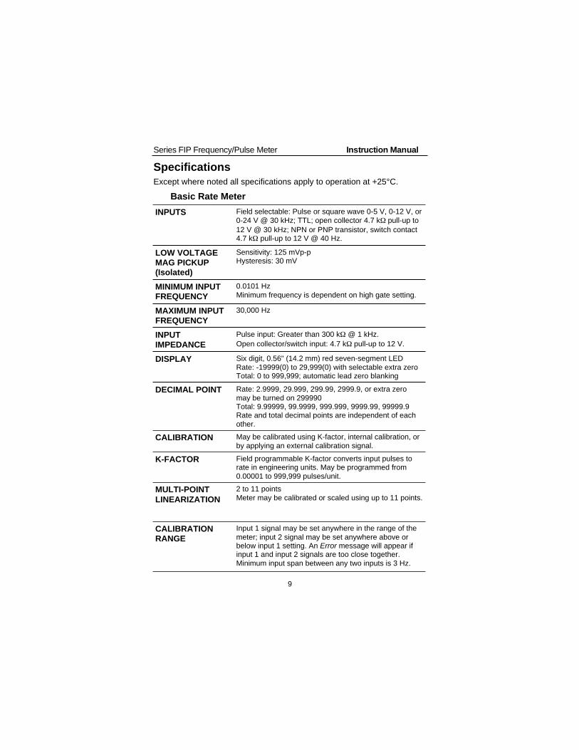
Specifications
Except where noted all specifications apply to operation at +25°C.
Basic Rate Meter
INPUTS Field selectable: Pulse or square wave 0-5 V, 0-12 V, or
0-24 V @ 30 kHz; TTL; open collector 4.7 k pull-up to
12 V @ 30 kHz; NPN or PNP transistor, switch contact4.7 k pull-up to 12 V @ 40 Hz.
LOW VOLTAGEMAG PICKUP(Isolated)
Sensitivity: 125 mVp-pHysteresis: 30 mV
MINIMUM INPUTFREQUENCY
0.0101 Hz
Minimum frequency is dependent on high gate setting.
MAXIMUM INPUTFREQUENCY
30,000 Hz
INPUTIMPEDANCE
Pulse input: Greater than 300 k @ 1 kHz.
Open collector/switch input: 4.7 k pull-up to 12 V.
DISPLAY Six digit, 0.56" (14.2 mm) red seven-segment LED
Rate: -19999(0) to 29,999(0) with selectable extra zeroTotal: 0 to 999,999; automatic lead zero blanking
DECIMAL POINT Rate: 2.9999, 29.999, 299.99, 2999.9, or extra zero
may be turned on 299990Total: 9.99999, 99.9999, 999.999, 9999.99, 99999.9Rate and total decimal points are independent of each
other.
CALIBRATION May be calibrated using K-factor, internal calibration, or
by applying an external calibration signal.
K-FACTOR Field programmable K-factor converts input pulses torate in engineering units. May be programmed from
0.00001 to 999,999 pulses/unit.
MULTI-POINT
LINEARIZATION
2 to 11 points
Meter may be calibrated or scaled using up to 11 points.
CALIBRATIONRANGE
Input 1 signal may be set anywhere in the range of the
meter; input 2 signal may be set anywhere above orbelow input 1 setting. An Error message will appear ifinput 1 and input 2 signals are too close together.
Minimum input span between any two inputs is 3 Hz.

Series FIP Frequency/Pulse Meter Instruction Manual
10
FILTER Programmable contact de-bounce filter: 40 to 950 Hz
maximum input frequency allowed (Low speed filter).
TIME BASE Seconds, minutes, or hours
GATE Low gate: 1-98 seconds
High gate: 2-99.9 seconds
OUTPUT
POWER
Isolated power supply field selectable, 12 VDC @
50 mA for sensor or 24 VDC ± 5% @ 20 mA for outputtransmitter, regulated. Maximum loop resistance is
1200 (AC powered units only).
ACCURACY ±0.1% FS
ALARM POINTS Four, any combination of high or low alarms
ALARM POINT
DEADBAND
0-100% FS, user selectable
ALARM STATUS
INDICATION
Front panel LED
PEAK HOLD
(MAX DISPLAY)
Captures the peak rate and displays it via the front
panel ENTER button (Dspy p)
PEAK HOLD
INDICATION
Front panel flashing R LED
LOCKOUT Jumper JP2 restricts modification of calibration values.
NON-VOLATILEMEMORY
All programming and totalizer values are stored in non-
volatile memory for a minimum of ten years if power islost.
POWER OPTIONS 115 or 230 VAC ±10%, 50/60 Hz, 12 VA
ISOLATION 1500 VAC
ENVIRONMENTAL Operational ambient temperature range: 0 to +60°C
Storage temperature range: -40 to +85°C
Relative humidity: 0 to 90% non-condensing
ENCLOSURE 1/8 DIN, high impact plastic, UL 94V-0
FRONT PANEL Type 4X, NEMA 4X, IP65; panel gasket provided. Someapplications require the use of silicone RTV to ensure a
Type 4X seal
MOUNTING 1/8 DIN panel cutout required.
Two panel mounting brackets provided.

Series FIP Frequency/Pulse Meter Instruction Manual
11
OVERALL
DIMENSIONS
2.30 x 4.25 x 5.30 in (58 x 108 x 135 mm)
WEIGHT 19.7 oz (559 g) (including options)
CONNECTIONS Removable screw terminal blocks, accept 12 to 22
AWG wire
WARRANTY 1 years parts & labor

Series FIP Frequency/Pulse Meter Instruction Manual
12
Rate/Totalizer/Batch Controller Features
RATE DISPLAYINDICATION
LED labeled R on right illuminates when meter is
displaying rate input.
LOW-FLOWCUTOFF
Any input below the low-flow cutoff value will result
in a display of zero. May be set from 1 count to100% F.S., user selectable. To disable low-flowcutoff, program cutoff value to zero.
In multi-point calibration/scaling, the total is based
on the rate display; so, inputs below the low-flowcutoff value will not affect the totalizer.
In K-factor scaling, the totalizer ignores the low-flowcutoff; the totalizer counts every incoming pulse
regardless of the rate display.
ALTERNATING
DISPLAY
Display may be programmed to alternate between
rate and total every 10 seconds.
TOTAL DISPLAY 0 to 999,999; automatic lead zero blanking
TOTAL DECIMAL
POINT
May be set in any of the following positions:
9.99999, 99.9999, 999.999, 9999.99, or 99999.9Total and rate decimal points are independent.
TOTALCONVERSION
FACTOR
Programmable from 0.00001 to 59999.
This is a multiplier applied to the rate display toobtain the total in any engineering units.
TOTALIZER In multi-point calibration/scaling, the meter
calculates the total based on rate display and fieldprogrammable total conversion factor to display totalin engineering units. Time base must be selected
according to time units in which rate is displayed.
In K-factor scaling, the meter calculates the total
based on the input pulses, K-factor value, and totalconversion factor.
TOTALIZER
ROLLOVER
Totalizer rolls over when display exceeds 999,999.
Relay status reflects the display.
TOTALIZER
PRESETS
Up to four, user selectable under setup menu Setup.
Any set point can be assigned to total and may beprogrammed anywhere in the range of the meter.
PRESET OFFSET Relays assigned to total can be programmed to trip
at any point below the next relay’s preset value.

Series FIP Frequency/Pulse Meter Instruction Manual
13
PROGRAMMABLE
DELAY ONRELEASE
If the meter is programmed to reset total to zero
automatically when the highest preset is reached,then a delay will occur before the total relays reset.This delay can be programmed anywhere between 1
and 999 seconds.
PRIORITY BATCH
PROGRAMMING
This feature allows the user to quickly change preset
values without going into the main menu by holdingthe ENTER button for more than 3 seconds.
TOTAL RESET Via front panel ENTER button, external contact
closure, or automatically via user selectable preset.
TOTAL RESETLOCKOUT
Meter may be programmed so total cannot be resetfrom the front panel.
Options
Relays
RATING 2 SPDT (Form C); rated 2 A @ 30 VDC or 2 A @250 VAC resistive load;
1/14 HP @ 125/250 VAC for
inductive loads
ASSIGNED TO
RATE OR TOTAL
Any relay may be assigned to rate or total.
ELECTRICAL
NOISESUPPRESSION
A suppressor (RC network) to prolong the life of the
relays should be connected to each relay contactswitching inductive loads. The suppressor provides
a degree of protection against electrical noisecaused by inductive loads. Recommendedsuppressor value, 0.01 F/470 , 250 VAC. See
page 80.
DEADBAND 0-100% FS, user selectable
HIGH OR LOW
ALARM
User may program any alarm for a high or low trip
point.
RELAY
OPERATION
Latching or non-latching, field selectable
FAIL-SAFE
OPERATION
Relay coils are energized in non-alarm condition. In
case of power failure, relays will go to alarm state.Fail-safe operation may be disabled, by removing
jumper JP6 located on the Display Board.
AUTO
INITIALIZATION
When power is applied to the meter, relays assigned
to total will reflect the state of the accumulated totalvalue in memory. Relays assigned to rate will reflect
the state of the input to the meter.

Series FIP Frequency/Pulse Meter Instruction Manual
14
RELAYS RESET User select via JP3 jumper array and SetuP menu
Total relays reset When total is reset to zero, if set up for external total
reset
After delay has elapsed, if set up for internal total
reset
Manual any time, if set up for external total reset (viauser supplied external contact closure at terminals
AK and CM or front panel ACK button)
Manual reset resets all manually resettable relays.
Rate relays reset Automatic reset only
Manual reset only, at any time
Automatic plus manual reset at any time
Manual reset only after alarm condition has been
corrected
Automatic reset: Relays will automatically resetwhen the input passes the reset point.
Manual reset: Performed via user supplied external
contact closure at terminals AK and CM or frontpanel ACK button. Manual reset resets all manuallyresettable relays.

Series FIP Frequency/Pulse Meter Instruction Manual
15
Isolated 4-20 mA Transmitter Output
CALIBRATION
RANGE
The transmitter output can be calibrated so that a
4 mA output is produced for any rate measured bythe meter. The 20 mA output may correspond to any
rate that is at least 501 counts greater or smallerthan the rate corresponding to 4 mA. (Ex. 4 mA = 0,20 mA = 501) If the span between 4 and 20 mA is
less than 501 counts, an error message will appear.
NO EQUIPMENTNEEDED
The 4-20 mA output from the meter is calibrated
without the use of a calibrator.
OUTPUT LOOPPOWER
24 VDC ± 5% @ 20 mA, regulated
Maximum loop resistance is 1200 . Output loop is
isolated from input.
ACCURACY ± 0.1% FS ± 0.004 mA
ISOLATION 500 VDC or peak AC, input-to-output or input/output-
to-24 VDC supply
EXTERNALLOOP-POWERSUPPLY
35 VDC max
OUTPUT LOOPRESISTANCE
Power supply Minimum Maximum
24 VDC 10 600
35 VDC (external) 600 1000

Series FIP Frequency/Pulse Meter Instruction Manual
16
Display Functions and Messages
The meter displays various functions and messages during operationand programming. The following table shows the various displayedfunctions and messages with their description.
Display Parameter Description/Comments
18888L Low Voltage Indicates an input voltage belowspecifications during power up.
-19999 Underrange Indicates the input signal is below thenegative range of the meter.
2 PtS 2 Points Indicates number of calibration pointsselected (2 to 11 points can be selected).
29999 Overrange Indicates the input signal exceeds the full-scale range of the meter.
CALIb External Calibration Calibrates meter using a calibrated signalsource.
CutoFF Low-Flow Cutoff Sets meter to display zero belowprogrammed cutoff point.
DECpt Decimal Point Sets the decimal position for total and rate
Delay Delay Sets delay on release between 1 and 999seconds for internal total reset.
DIA9 Diagnostic Displays parameter settings one at a time fordiagnostic purposes. Setting cannot bechanged under this function.
DspLAy Display Sets menu title scroll, selections are activatedwith lockout jumper installed.
Dspy 1 Display 1 Value displayed at input 1.
Dspy 2 Display 2 Value displayed at input 2.
DSPy P Display Peak Displays the highest rate value captured.
DSPy r Display Rate Sets rate as default display.
DSPy t Display Total Sets total as default display.
E rSt External Total Reset Indicates total does not reset to zero whenpreset value is reached.
E-CAL External Calibration Sets meter to be calibrated using a calibratedsignal source.
Error Error Indicates calibration was not successful.
Error1 Error 1 Indicates a combination of parameters thatexceeds the totalizer capabilities.
FActor K-factor Scaling Programs unit to convert input pulse to rate inengineering units.
FILtEr Filter Sets filter value from 2 to 50. Maximumfrequency is 950 to 40 Hz respectively.
Gate Gate Sets low and high gate values to allow ratedisplay of slow pulse rates.

Series FIP Frequency/Pulse Meter Instruction Manual
17
Display Parameter Description/Comments
Hour Hour Sets time base to display rate in units perhour.
HI High Gate Sets high gate value from 2.0 to 99.9
HI SPd High Speed Filter Sets meter to high speed filter. Maximumfrequency is 30,000 Hz.
I or e Internal or External Sets operation of total reset; internal orexternal.
I rSt Internal Total Reset Indicates total will reset to zero when highestpreset value is reached.
I-CAL Internal Calibration Sets meter for internal calibration to scalemeter without applying an input signal.
Inpt 1 Input 1 Sets Input 1 value.
Inpt 2 Input 2 Sets Input 2 value.
LatCk Latch Sets rate set points for latching or non-latching relay operation.
LO Low Gate Sets low gate value from 1.0 to 98.9
LO SPd Low Speed Filter Sets meter for low speed filter. Maximumfrequency is 950 Hz.
min Minute Sets time base to display rate in units perminute.
No PtS Number of Points Sets meter for 2 to 11 calibration points.
OFFSET Preset Offset Sets preset offset value (relay n trips at apoint below relay n+1 preset value).
outPut Output Sets the optional 4-20 mA output values.
PtS Multi-PointCalibration
Selects internal or external, multi-pointcalibration. Power up meter with ENTERbutton pressed.
R or t Rate or Total Assigns relay set points to rate or total.
Rate Rate Sets rate decimal point, or it Indicates setpoint was assigned to rate.
Rset P Reset Peak Erases peak value from memory andcaptures a new peak reading.
RSEt t Reset Total Resets the totalizer to zero.
SCALE Scale Scales meter using internal calibration fordesired display (signal source not required).
SeC Second Sets time base to display rate in units persecond.
SEt 1 Set Point 1 Sets operation and value for set point 1.
SEt 2 Set Point 2 Sets operation and value for set point 2.
SEt 3 Set Point 3 Sets operation and value for set point 3.
SEt 4 Set Point 4 Sets operation and value for set point 4.

Series FIP Frequency/Pulse Meter Instruction Manual
18
Display Parameter Description/Comments
SetPtS Set Points Sets alarm set /reset points and total presets.
Setup Setup Sets operation of set points for rate or total,latching or non-latching, etc.
t bASE Time Base Sets meter with correct time unit factor(seconds, minutes, or hours).
Tot CF Totalizer ConversionFactor
Sets multiplier factor to display total in anyengineering unit.
TotAL Total Sets total decimal point, or it indicates setpoint was assigned to total.
y or n Yes or No Sets selection or de-selection of variousfunctions.
SETUP AND PROGRAMMING
Overview
Setting up and programming the meter involves three basic steps:
1. Jumper Configuration (Page 19)a. Input selection and lockout jumpers
b. Relay acknowledge enablec. Fail-safe operation of relays
2. Connections (Page 20)a. Powerb. Input signalc. Acknowledgement and reset totald. Relayse. 4-20 mA output
3. Programming (Page 29)a. Basic meterb. Rate meterc. Totalizerd. Batch controllere. Relaysf. 4-20 mA outputg. Lockout and display selection
Programmed Parameter Settings
To simplify programming, write down the desired programming settings
prior to attempting to program the meter. The Programmed ParameterSettings form located on page 84 provides a convenient method torecord the user settings; it also provides the factory settings for most ofthe programmable parameters.

Series FIP Frequency/Pulse Meter Instruction Manual
19
Jumpers and Switch Configuration
OverviewBefore programming the meter, it is necessary to configure three jumper arraysand switch S1. The jumper arrays and switch S1 are used for setting the type of
input signal; excitation voltage, enable relay acknowledgement (ACK), andsetting relay fail-safe operation. Removing the lockout jumper enables theprogramming functions.
Jumper Arrays & Switch Function
Function Label Location Diagram
Input Signal JP5, JP7, S1
Excitation JP1
Lockout JP2
Main Board Figure 1
Relay ACK Enable JP3 Display Board Figure 2
Fail-Safe JP6 Display Board Figure 2
CM R AK
MAIN PCB
S+
4.7k Internal
Resistor+12V+5V
JP5
JP7
S-P-P+
1 3
2
1 3
2
Signal
LOCKOUT
EXCITATIONINPUT
SELECTION
S1
JP
1
JP
2
JP
51
23
JP
71
23
AB
Figure 1. Input Signal Selection & Lockout
FunctionJP5(1-2)
JP5(2-3)
JP7(1-2)
JP7(2-3)
SwitchS1
JP1 JP2
±125 mV to ±12 V
Pulse InputOff On Off On B
0-5 V Pulse Input On Off Off On A
0-24 V Pulse Input Off On Off On A
NPN Input Off On Off On A
PNP Input Off On On Off A
12 VDC (P+, P-)
ExcitationOn
24 VDC (P+, P-)Excitation
Off
Lockout On

Series FIP Frequency/Pulse Meter Instruction Manual
20
12
ACK ENABLE
JUMPERSFAIL-SAFE
JUMPERJP6JP3
SOLDER
PADS
Figure 2. Relay Acknowledge Enable & Fail-Safe Jumper
Relay Acknowledge Enable (Display Board)
Jumper JP3 Position Function
1 Enable relay 1 manual reset
2 Enable relay 2 manual reset
Fail-Safe Operation of Relays (Display Board)
Jumper
JP6 Position
Function
On Apply fail-safe function to the relays
Off Disable fail-safe function to the relays
Series FIP Frequency/Pulse Meter Instruction Manual
21
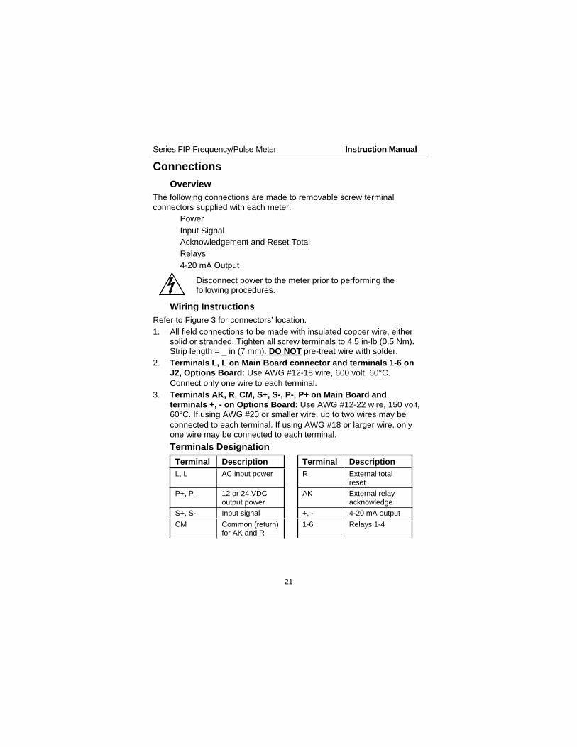
Connections
Overview
The following connections are made to removable screw terminal
connectors supplied with each meter:
• Power
• Input Signal
• Acknowledgement and Reset Total
• Relays
• 4-20 mA Output
Disconnect power to the meter prior to performing thefollowing procedures.
Wiring Instructions
Refer to Figure 3 for connectors’ location.
1. All field connections to be made with insulated copper wire, eithersolid or stranded. Tighten all screw terminals to 4.5 in-lb (0.5 Nm).Strip length = _ in (7 mm). DO NOT pre-treat wire with solder.
2. Terminals L, L on Main Board connector and terminals 1-6 on
J2, Options Board: Use AWG #12-18 wire, 600 volt, 60°C.
Connect only one wire to each terminal.
3. Terminals AK, R, CM, S+, S-, P-, P+ on Main Board and
terminals +, - on Options Board: Use AWG #12-22 wire, 150 volt,60°C. If using AWG #20 or smaller wire, up to two wires may be
connected to each terminal. If using AWG #18 or larger wire, onlyone wire may be connected to each terminal.
Terminals Designation
Terminal Description Terminal Description
L, L AC input power R External totalreset
P+, P- 12 or 24 VDCoutput power
AK External relayacknowledge
S+, S- Input signal +, - 4-20 mA output
CM Common (return)for AK and R
1-6 Relays 1-4

Series FIP Frequency/Pulse Meter Instruction Manual
22
AC Power and Signal Connector
L L P+ P- S- S+ CM R AK
MAIN PCB
AC
PWR
LOCKOUT
EXCITATIONINPUT
SELECTION
S1
JP
1
JP
2
JP
51
2
3
JP
71
2
3
AB
Figure 3. AC Power & Signal Connector Diagram

Series FIP Frequency/Pulse Meter Instruction Manual
23
Power Connections
Disconnect power to the meter before making any connections.
Connecting 230 VAC to meters designed for 115 VAC will result indamage to the instrument as well as endanger personnel.
!Do not connect power or earth ground to any unused or CM terminals.
Connect power to terminals L and L on Main Board screw terminalconnector, located at the rear of the instrument.
Notice:
• Primary voltages must not be accessible to the user.
• Primary wires must be installed in accordance to the applicable
standards.
• Keep the primary wires separated from signal cables.
L L S- S+ CM R AK
MAIN PCB
PWR
Figure 4. Input Power Connections

Series FIP Frequency/Pulse Meter Instruction Manual
24
Signal Connections
Signal connections are made to the connector on the Main Board. Thisconnector also includes connections for power, acknowledgement, resettotal, and common. Refer to Figure 3 for location.
L L P+ P- S- S+ CM R AK
PWR
MAIN PCB
Flowmeter
(Pulse output)
Figure 5. Flowmeter Powered by Internal Power Supply
L L P+ P- S- S+ CM R AK
PWR
MAIN PCB
Flowmeter
(Pulse output)
External
Power
Supply
+-
Figure 6. Flowmeter Powered by External Supply

Series FIP Frequency/Pulse Meter Instruction Manual
25
L L P+ P- S- S+ CM R AK
PWR
MAIN PCB
Flowmeter
(Magnetic Pickup)
Figure 7. Self-Powered Magnetic Pickup Flowmeter
L L P+ P- S- S+ CM R AK
MAIN PCB
NPN
V+
Output
Com
SENSOR
PNP
SENSOR
Figure 8. Open Collector Transistor Output

Series FIP Frequency/Pulse Meter Instruction Manual
26
L L P+ P- S- S+ CM R AK
PWR
MAIN PCB
SWITCH CONTACT
JP7
4.7k Internal
Resistor1
2
3 +12V+5V
1
2
3
Signal
JP5
Figure 9. Switch Contact Closure
Acknowledgement, Reset Total ConnectionsAcknowledgement and reset total terminals provide a convenientmethod to remotely access the following functions:
Terminal Function
AK Acknowledges or resets relays, exitmenu scroll, diagnostic and calibration.
R Resets total to zero.
L L P+ P- S- S+ CM R AK
MAIN PCB
RESET
TOTALACK
Figure 10. External Control Connections

Series FIP Frequency/Pulse Meter Instruction Manual
27
Optional Relays and 4-20 mA Output Terminals
Depending on the model number, the Options Board may contain 2relays and an isolated 4-20 mA output transmitter. Relay connectionsare made to removable screw terminal connectors located at J2 and J3on the Options Board. Connections for the isolated 4-20 mA outputoption are made to J1 on the Options Board.
FunctionScrew Terminal
ConnectorPin Number
Transmitter + J1 1
Transmitter - J1 2
Relay 1 Common J2 1
Relay 1 NC J2 2
Relay 1 NO J2 3
Relay 2 Common J2 4
Relay 2 NC J2 5
Relay 2 NO J2 6
LLP+P-S-S+CMRAK
J1J2
+-123456
Figure 11. Connectors Location - Rear View of Meter

Series FIP Frequency/Pulse Meter Instruction Manual
28
Isolated 4-20 mA Output Option Connections
The meter can be equipped with an isolated 4-20 mA output signaloption that can be programmed to produce a 4-20 mA output for virtuallyany rate display with at least a 501 count span.
The following diagrams illustrate the 4-20 mA output signal beingpowered from the meter’s internal power supply and by an externalpower supply.
+-
LLP+P-S-S+CMRAK
J1 Meter,
Recorder,
Controller,
etc+
-
Figure 12. Output Loop Powered by Meter
+-
LLP+P-S-S+CMRAK
J1
Loop
Power
Supply
+
-
Meter,
Recorder,
Controller,
etc+
-
Figure 13. Output Loop Powered from External Supply
If the output loop is powered by an external supply, the looppower supply must be turned on before the meter is turnedon. Otherwise, the output loop signal may be incorrect.

Series FIP Frequency/Pulse Meter Instruction Manual
29
Programming
Overview
The meter is programmed using the ENTER button, three jumper
arrays, and switch S1. The ENTER button is used to calibrate the meter,program various totalizer functions, and to set alarm trip and resetpoints. The jumper arrays are used for programming the input signal,lockout, relay acknowledge enable, and relay fail-safe operation. Thissection of the manual deals with programming the following aspects ofthe meter:
• Basic Meter Programming
• Rate Meter Setup
• Totalizer Programming
• Set Point Setup and Programming
• Isolated 4-20 mA Output Programming (output)
• Lockout and Display Selection Programming
General Programming Description
All programming is performed using the ENTER button. To set up afunction there are sequential steps that have to be performed. As each
step progresses, either a single digit or the entire display will flash. Theflashing digit, or flashing display, will be looking for acknowledgement ifit is the desired digit or display. Pressing the ENTER button will acceptthe value. If the flashing display or digit is not the one desired, wait andthe value will change.
Each digit will flash for 3 seconds before it starts to change, when it is
accepted the next digit will flash for 3 seconds. This procedure willcontinue until the ENTER button is pressed while the desired option isflashing. As the programming progresses there will be times when adecision has to be made, an example is yes or no ( y or n ).
ENTER and ACK FunctionalityThe ENTER button is used to program the meter for various functions.
The ACK button is used to acknowledge the relays during operation andto quit main menu scroll during programming, diagnostic menu, andcalibration.

Series FIP Frequency/Pulse Meter Instruction Manual
30
Five Basic Digit/Display Setting Instructions1. If flashing display is OK, press ENTER to accept it, before display
stops flashing.
2. If flashing display is not OK, (or if ENTER was not pressed in timeto accept it), wait for the first digit to flash.
3. If a flashing digit is OK, press ENTER to accept it, before it starts toscroll.
4. If a flashing digit is not OK, (or if ENTER was not pressed in time toaccept it) wait for digit to scroll, and press ENTER when OK.
5. Digits will scroll until ENTER is pressed. When a digit is acceptedby pressing ENTER, next digit flashes.
The display will scroll through the following main menu functions in theorder shown:
Display Type of Function
Dspy r or
Dspy tDisplays rate or display total.
Rset t Resets total to zero.
Dspy p Displays and hold peak reading.
FActor, CALIb orSCale
Calibrates meter after setting it for K-factor,external or internal calibration.
Cutoff Sets low-flow cutoff point.
T base Sets time base.
Tot Cf Sets totalizer conversion factor.
dECpt Sets rate and total decimal point.
SetupSets set points for rate or total, latching or non-latching relays.
SetPtS Sets alarms set/reset points and batch presets.
outputSets 4-20 mA output values, if option isinstalled.
Dsplay Includes or excludes menu titles from scroll.
dIA9Displays parameter settings one at a time fordiagnostic purposes.
To quit main menu scroll, diagnostic menu, calibration, or scaling pressACK while displaying menu item or while display is flashing input n ordisplay n, where n is the input or display number.

Series FIP Frequency/Pulse Meter Instruction Manual
31
Press
ENTER
Is
flashing display
OK?
NO
YES
YES
NO
YES
NO
Press ENTER
when FActor
appears
999.999
appears; select
decimal point
Press ENTER
Wait for digit
to flash
Is flashing
digit OK?
Wait for digit
to scroll
Press ENTER
when OKPress ENTER
Is
entire display
flashing?
K-factor
Scaling
Complete!
Press ENTER
NO
Figure 14. K-Factor Scaling Flowchart
Series FIP Frequency/Pulse Meter Instruction Manual
32
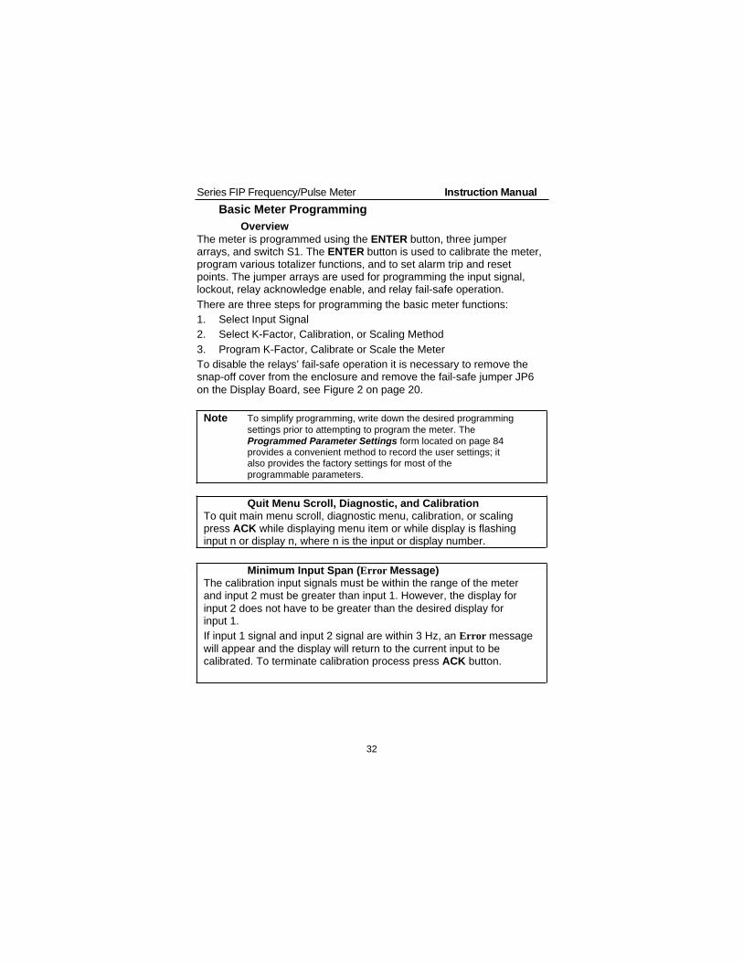
Basic Meter Programming
Overview
The meter is programmed using the ENTER button, three jumperarrays, and switch S1. The ENTER button is used to calibrate the meter,program various totalizer functions, and to set alarm trip and resetpoints. The jumper arrays are used for programming the input signal,lockout, relay acknowledge enable, and relay fail-safe operation.
There are three steps for programming the basic meter functions:
1. Select Input Signal
2. Select K-Factor, Calibration, or Scaling Method
3. Program K-Factor, Calibrate or Scale the Meter
To disable the relays’ fail-safe operation it is necessary to remove thesnap-off cover from the enclosure and remove the fail-safe jumper JP6
on the Display Board, see Figure 2 on page 20.
Note To simplify programming, write down the desired programming
settings prior to attempting to program the meter. The
Programmed Parameter Settings form located on page 84provides a convenient method to record the user settings; italso provides the factory settings for most of the
programmable parameters.
Quit Menu Scroll, Diagnostic, and CalibrationTo quit main menu scroll, diagnostic menu, calibration, or scalingpress ACK while displaying menu item or while display is flashinginput n or display n, where n is the input or display number.
Minimum Input Span (Error Message)The calibration input signals must be within the range of the meterand input 2 must be greater than input 1. However, the display for
input 2 does not have to be greater than the desired display forinput 1.
If input 1 signal and input 2 signal are within 3 Hz, an Error message
will appear and the display will return to the current input to becalibrated. To terminate calibration process press ACK button.

Series FIP Frequency/Pulse Meter Instruction Manual
33
Select Input SignalThe meter can be programmed to accept all the common pulse inputsand contact closure signals using jumper JP5, JP7, and S1 switchlocated on the Main Board, at the rear of the instrument. Jumper JP1sets the excitation voltage to 12 VDC or 24 VDC.
CM R AK
MAIN PCB
S+
4.7k Internal
Resistor+12V+5V
JP5
JP7
S-P-P+
1 3
2
1 3
2
Signal
LOCKOUT
EXCITATIONINPUT
SELECTION
S1
JP
1
JP
2
JP
51
23
JP
71
23
AB
Figure 15. Input Signal Selection & Lockout
FunctionJP5(1-2)
JP5(2-3)
JP7(1-2)
JP7(2-3)
SwitchS1
JP1 JP2
±125 mV to ±12 V
Pulse InputOff On Off On B
0-5 V Pulse Input On Off Off On A
0-24 V Pulse Input Off On Off On A
NPN Input Off On Off On A
PNP Input Off On On Off A
12 VDC (P+, P-)
ExcitationOn
24 VDC (P+, P-)
ExcitationOff
Lockout On
The meter can also be programmed to restrict personnel from making
changes to the meter’s programming by installing a jumper over JP2pins on Main Board. For a complete description of the Lockout andDisplay Selection Programming features, see page 62.

Series FIP Frequency/Pulse Meter Instruction Manual
34
Select K-Factor, Calibration, or Scaling MethodThe meter may be scaled using the K-factor function, calibrated usingan external signal source such as a calibrator, or scaled using theinternal source with the I-CAL (internal calibration) feature. With I-CAL,a frequency input signal can be scaled for any display range without
applying a signal.
To select Calibration Method, apply power with ENTER button pressed.
1. When display stops flashing, release ENTER button. Display
alternates between PtS and FActor.
2. To select multi-point calibration/scaling, press ENTER when PtS is
displayed.
3. To calibrate meter with an external source, such as a calibrator,press ENTER when E-CAL appears.
4. To scale meter with internal source, press ENTER when I-CAL
appears.
After the calibration method has been selected, the meter returns toreading mode. To perform K-factor scaling, calibration, or scaling follow
the corresponding procedure on pages 36-39.

Series FIP Frequency/Pulse Meter Instruction Manual
35
Set Rate and Total Decimal PointThe totalizer decimal point may be set independently of the rate decimalpoint. For instance, it is possible to have a rate decimal point set at2999.9 and a totalizer decimal point set at 999.999.
Set decimal point
Press ENTER when the dECPt (decimalpoint) function appears. The display movesto the total and rate decimal point
functions. If ENTER is not pressed within 3seconds the display moves on to the nextfunction to be programmed.
dECPt
Set totalizer decimal pointPress ENTER when the totAL (totalizer
decimal point) function appears.
Total
Select the desired decimal point location by pressingENTER when the decimal point is in the desiredlocation. If no decimal point is required press ENTERwhen the decimal point is not shown. The display
moves to the rate decimal point function.
99999.9
final
9999.99
Set rate decimal point
Press ENTER when the rAtE (rate decimal
point) function appears.
rAtE
The decimal point will begin to scroll, and a zero will
be displayed for the sixth digit. Select decimal pointlocation or extra zero by pressing ENTER whendecimal point is in the required location or extra zerois displayed. If no decimal point is required, pressENTER when the decimal point is not shown.
299.99
final
2999.9

Series FIP Frequency/Pulse Meter Instruction Manual
36
Scale or Calibrate the MeterThe meter may be scaled using the K-factor function, calibrated usingan external signal source such as a calibrator, or scaled using the
internal source with the I-CAL (internal calibration) feature. With I-CAL,
a frequency input signal can be scaled for any display range withoutapplying a signal.
Scale Using K-Factor (FActor)
Set K-factorPress ENTER when the FActor (K-factor)
function appears. The display moves tosetting the K-factor decimal point.
FActor
Select the desired decimal point location by pressing
ENTER when the decimal point is in the desiredlocation. If no decimal point is required press ENTERwhen the decimal point is not shown. The displaymoves to setting the K-factor value.
99999.9
final
9999.99
Set K-factor value
The entire display will flash for three seconds. Forinstructions, see Five Basic Digit/Display Setting
Instructions, page 30.
001.000
final
1000.00
Scale Using Internal Calibration (I-CAL)
Note To simplify programming, write down the desired programming
settings prior to attempting to program the meter. TheProgrammed Parameter Settings form located on page 84
provides a convenient method to record the user settings; italso provides the factory settings for most of theprogrammable parameters.
Press ENTER, then press it again whenthe SCale (scale) function appears.
SCale
Select the number of calibration pointsIf ENTER is not pressed when no. pts is displayed,the number of points will default to whatever wasselected previously. To program the number of
calibration points, press ENTER while no. pts isflashing. When desired number of points isdisplayed, press ENTER.
No. pts
then
2
...
11

Series FIP Frequency/Pulse Meter Instruction Manual
37
Set the first calibration point
INPT 1 (input 1) flashes indicating that themeter is ready to be programmed for theinput corresponding to the first calibrationpoint. Press ENTER.
Inpt 1
Set the input for the first calibration point
The entire display will flash for three seconds. Forinstructions, see Five Basic Digit/Display SettingInstructions, page 30.
00000.0
final input 1
00020.0
Set display for the first calibration point
Dspy 1 (display 1) flashes indicating thatthe meter is ready to be programmed forthe display corresponding to the firstcalibration point. Press ENTER.
Dspy 1
Program the display for Dspy 1 (display 1) asdescribed above when the input for the firstcalibration point was programmed.
00000
final display 1
00020
Calibration Error (error)A meter display of Error during calibration indicates that the calibration
process was not successful. The meter should be recalibrated.
The Error message will appear if input 1 signal and input 2 signal are
too close together. Refer to Minimum Input Span (Error Message),page 32.
The Error message will appear if input 1 signal is inadvertently also
applied for input 2 calibration, or ENTER is pressed before applyinginput 2.

Series FIP Frequency/Pulse Meter Instruction Manual
38
Set the second calibration point
INPT 2 (input 2) flashes indicating that themeter is ready to be programmed for theinput corresponding to the secondcalibration point. Press ENTER.
Inpt 2
Set the input for the second calibration point
Program the display for INPT 2 (input 2) as
described above when the input for the firstcalibration point was programmed.
10000.0
then
20000.0
Set display for the second calibrationpoint
Dspy 2 (display 2) flashes indicating thatthe meter is ready to be programmed forthe display corresponding to the second
calibration point. Press ENTER.
Dspy 2
Program the display for Dspy 2 (display 2) asdescribed above when the input for the firstcalibration point was programmed.
10000
final display 2
20000
Set the display for the remaining calibration points, if selected.
Decimal point is set up under decimal point menu (dECPt).

Series FIP Frequency/Pulse Meter Instruction Manual
39
Calibrate Using External Calibration (E-CAL)Note To simplify programming, write down the desired programming
settings prior to attempting to program the meter. TheProgrammed Parameter Settings form located on page 84
provides a convenient method to record the user settings; italso provides the factory settings for most of theprogrammable parameters.
Press ENTER, then press it again when theCalIb (calibrate) function appears.
CalIb
Select the number of calibration pointsIf ENTER is not pressed when no. pts is displayed,the number of points will default to whatever wasselected previously. To program the number ofcalibration points, press ENTER while no. pts is
flashing. When desired number of points isdisplayed, press ENTER.
No. pts
then
2
…
11
Apply the signal for the first calibration
point
INPT 1 (input 1) flashes indicating that the
meter is ready to accept a signal for the firstcalibration point. Apply the desired signaland press ENTER.
Inpt 1
Set the display for the first calibration point
The entire display will flash for three seconds.Program display value per Five Basic Digit/DisplaySetting Instructions, page 30.
00000
final display 1
00020
Apply signal for the second calibrationpoint
INPT 2 (input 2) flashes indicating that themeter is ready to accept a signal for thesecond calibration point. Apply the desiredsignal and press ENTER.
Inpt 2
Set the display for the second calibration point
Program the display as described above when the
display for the first calibration point wasprogrammed.
10000
final display 2
20000
Set the display for the remaining calibration points, if selected.

Series FIP Frequency/Pulse Meter Instruction Manual
40
Gate Function (Gate)
The gate function is used for displaying slow pulse rates. In the previous version
of this meter, the minimum rate that could be displayed was 0.33 pulse/sec.Using the programmable gate, the meter is able to display pulse rates as slow as1 pulse every 99 seconds (0.0101 pulse/sec). The gate function can also be used
to obtain a steady display reading with a fluctuating input signal.
The gate function (Gate) has been added to t bASE menu. After time base is
selected, Gate will appear. If there is no need to change gate setting, let it time
out without pressing ENTER. There are two settings for the Gate, low gate (LO)
and high gate (HI).
Low Gate (LO)For most applications, low gate setting should be left at 1.0 second. Increase low
gate setting to obtain a steadier rate display. The rate display will update inaccordance with the low gate setting, for example if low gate is set at 10.0, thedisplay will update every 10 seconds; changes in rate between updates will not
be reflected until next display update.
High Gate (HI)
Set the high gate value to correspond to the highest expected pulse width (lowestpulse rate). For instance if the meter must display a rate when there is 1 pulse
coming into the meter every 10 seconds, set the high gate to 11.0 seconds.When the signal is removed from the meter, the display will show the last readingfor 11 seconds; then it will read zero.
Programming the Gate (Gate)
Press ENTER, then press it again whenthe t bASE (time base) function appears.
Select appropriate time base, after timebase has been selected Gate appears.Press ENTER to set gate values.
t bASE
then
SEC
then
GatE
Low gate function and setting will bedisplayed. Press ENTER to accept lowgate value. Display will show high gatefunction and setting, change value asrequired.
After gate values have been
programmed, the meter moves on to thenext function to be programmed.
LO
then
00001.0
then
HI
then
00003.0

Series FIP Frequency/Pulse Meter Instruction Manual
41

Series FIP Frequency/Pulse Meter Instruction Manual
42
Contact De-Bounce Filter (FILter)
The filter function (FILter) can be used for applications where the meter is set up
to count pulses generated by switch contacts. The filter value can be setanywhere between 2 and 50, the higher the value, the greater the filtering.
To access this feature, power up the meter with ACK button pressed. When
display comes on release ACK button, display will alternate between HI SPd
(high speed) and LO SPd (low speed), press ENTER when LO SPd is displayed
to enable filter function. The filter function (FILter) appears at the end of the main
menu scroll with low speed filter selected. Program the filter value, so that thereare no extra counts when contact closure is completed.
Gate and Filter Settings
Contact De-Bounce Filter Slow Pulse Rate
Filter
Setting
Speed
Setting
Max Freq
Hz
Low
Gate**
High
Gate
Min Pulse
Rate (p/s)
Min Freq*
Hz
2 LO 950 1 3.1 1/3 0.3333
4 LO 450 1 10.1 1/10 0.1000
10 LO 200 1 30.1 1/30 0.0333
25 LO 75 1 60.1 1/60 0.0167
50 LO 40 1 90.1 1/90 0.0111
N/A HI 30,000 1 99.1 1/99 0.0101
* Minimum frequency is dependent on high gate setting.
** Low gate setting can be used to stabilize display reading with
fluctuating signal.
NOTE: (Input frequency) x (Low gate) must be < 65,000. Otherwise,display goes overrange.

Series FIP Frequency/Pulse Meter Instruction Manual
43
Rate Meter Setup
Overview
The meter can be used to display flow rate. In addition to the scalingand calibration procedures described above, the only setup required forthis type of application is setting the meter to display rate, andprogramming the low-flow cutoff if required.
Set Display to Rate (dSPy r)
The user may select either rate or total to be set as the defaultdisplayed reading. When displaying rate, the rate LED indicator will beilluminated.
To change the display from reading totalto rate
Press ENTER to begin scrolling through thefunctions.
ENTER ACK
When dspy r (display rate) appears,press ENTER.
ENTER ACK
dSPY r
The meter now displays rate and the greenR LED on the right side is illuminated.
ENTER ACK

Series FIP Frequency/Pulse Meter Instruction Manual
44
Low-Flow Cutoff Programming (Cutoff)
The low-flow cutoff feature allows the meter to be programmed so thatany input below the cutoff point is always displayed as zero on the ratedisplay.
In multi-point calibration/scaling, the total is based on the rate display;
so, inputs below the low-flow cutoff value will not affect the totalizer.
In K-factor scaling, the totalizer ignores the low-flow cutoff; the totalizercounts every incoming pulse regardless of the rate display.
To set the low-flow cutoff point Cutoff
Press ENTER, then press it again whenCutoff (low-flow cutoff) appears.
Cutoff
The entire display will flash for three seconds.Program low-flow cutoff value per Five BasicDigit/Display Setting Instructions, page 30.
NOTE: To disable low-flow cutoff, reprogram thevalue to zero.
-19.999
then
01.000
then
01.500
final
01.520

Series FIP Frequency/Pulse Meter Instruction Manual
45
Totalizer Programming
Overview
The meter can also be used to display total flow. There are fivefunctions to be programmed to allow the meter to act as a flow totalizer:
1. Set display to total
2. Set rate time base
3. Set totalizer conversion factor
4. Set totalizer decimal point
5. Set alternating display (if needed)
Set Display for Total (dSPy t)The user may select either rate or total to be set as the default
displayed reading. When displaying rate, the green rate LED indicatorwill be illuminated.
To change the display from reading rateto total
The meter is now displaying rate, asindicated by the green LED illuminated onthe right side of the display. Press ENTERto begin scrolling through the functions.
ENTER ACK
50.25
When dspy t (display total)
appears, press ENTER.
ENTER ACK
dSPY t
The meter now displays total.
ENTER ACK
45657

Series FIP Frequency/Pulse Meter Instruction Manual
46
Set Rate Time Base (t baSE)
To act as a totalizer, the meter must be programmed with the same timebase as the flowmeter. The time base is the time units in which the rateis displayed. For example, if the rate is in gallons per hour then the timebase must be set to kour.
To set the time base t base
Press ENTER, then press it again when thet basE (time base) function appears.
T base
The different units of time will scroll: minute, hour,
second. Press ENTER when the required unit isdisplayed.
The display moves to setting the gate function. IfENTER is not pressed within 3 seconds, the displaymoves to the next function to be programmed. Refer
to page 40.
min
or
Hour
or
seC
Set Totalizer Conversion Factor (tot CF)The totalizer conversion factor is a number that is multiplied by the rate
to compute the total. For example, if the rate display is gallons per hourand total is desired in barrels, (1 gallon = .02381 barrels) a totalconversion factor of .02381 should be used. If the rate display is gallonsper hour and total is desired in gallons, a factor of 1 should be used.
The factor has a selectable decimal point. Because the decimal point ismathematically significant, values such as 1.0000, 1.0, and 1 produce
identical results. However, values such as 1.1111, 1.1, and 1 producedifferent results. The decimal point should be set so as to produce thebest resolution for the application. The maximum value for the totalizerconversion factor depends upon the decimal point selection.
Number of Decimal Places Maximum Conversion Factor
0 59999
1 5999.9
2 599.99
3 59.999
4 5.9999
5 0.59999
Series FIP Frequency/Pulse Meter Instruction Manual
47
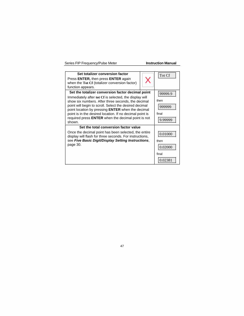
Set totalizer conversion factor
Press ENTER, then press ENTER againwhen the Tot Cf (totalizer conversion factor)
function appears.
Tot Cf
Set the totalizer conversion factor decimal point
Immediately after tot Cf is selected, the display willshow six numbers. After three seconds, the decimalpoint will begin to scroll. Select the desired decimalpoint location by pressing ENTER when the decimal
point is in the desired location. If no decimal point isrequired press ENTER when the decimal point is notshown.
99999.9
then
999999
final
9.99999
Set the total conversion factor value
Once the decimal point has been selected, the entiredisplay will flash for three seconds. For instructions,see Five Basic Digit/Display Setting Instructions,page 30.
0.01000
then
0.02000
final
0.02381

Series FIP Frequency/Pulse Meter Instruction Manual
48
Set Totalizer Decimal PointThe totalizer decimal point may be set independently of the rate decimalpoint. For instance, it is possible to have a rate decimal point set at
2999.9 and a totalizer decimal point set at 999.999. Rate decimal pointsetting instructions are also explained below, ignore if the rate decimalpoint has been set up already.
Set decimal point
Press ENTER when the dECPt (decimal
point) function appears. The display movesto the total and rate decimal pointfunctions. If ENTER is not pressed within 3seconds the display moves on to the nextfunction to be programmed.
dECPt
Set totalizer decimal point
Press ENTER when the totAL (totalizerdecimal point) function appears.
Total
Select the desired decimal point location by pressing
ENTER when the decimal point is in the desiredlocation. If no decimal point is required press ENTERwhen the decimal point is not shown. The displaymoves to the rate decimal point function.
99999.9
final
9999.99
Set rate decimal point
Press ENTER when the rAtE (rate decimalpoint) function appears.
rAtE
The decimal point will begin to scroll, and a zero willbe displayed for the sixth digit. Select decimal pointlocation or extra zero by pressing ENTER whendecimal point is in the required location or extra zerois displayed. If no decimal point is required, pressENTER when the decimal point is not shown.
299.99
final
2999.9

Series FIP Frequency/Pulse Meter Instruction Manual
49
Set Alternating Total/Rate DisplayThe display may be programmed to automatically toggle between rateand total every ten seconds. The alternating display is set up by
selecting n (no) for both, dSPy r (display rate) and dSPy t (display total)on the dSPLAy (display) menu.
Set alternating total/rate display
Press ENTER, then press it again whendsplay (display) function appears.
Dsplay
Press ENTER when DSPY r (display rate)appears
DSPY r
Y or n (yes or no) will flash alternately. Press ENTER
when n (no) appears.Y or n
Press ENTER when DSPY t (display total)appears
DSPY t
Y or n (yes or no) will flash alternately. Press ENTERwhen n appears.
Y or n
NOTE: Selections made through the display menu can be made withor without the lockout jumper installed, but only become active whenthe lockout jumper is installed.
This completes the calibration and
setup of the Basic Meter andTotalizer
Parameter Combinations Resulting in error1 Message
Certain extreme combinations of parameter selections may exceed thetotalizer range of the meter. If this occurs, the meter will momentarilydisplay Error 1 immediately after a programming operation. Steps to
correct this situation are:
Increase the number of decimal places in rate or totalizer conversionfactor, or
Decrease the number of decimal places in total.

Series FIP Frequency/Pulse Meter Instruction Manual
50
Set Point Setup and Programming
OverviewThe meter is available with 4 alarm points and corresponding front panelstatus LEDs as a standard feature. The front panel LEDs are useful foralarm applications that require visual notification only. For applicationsthat require relay contacts, such as driving external alarm devices or
batch controlling, the meter can be equipped with either two or fourrelays. Any of these relays may be assigned to rate or total.
Programming the relays involves four steps:
1. Setting the relay manual reset (ACK enable) jumpers:
These jumpers (JP3) are located on the Display Board anddetermine if a relay can be reset manually.
2. Setting the fail-safe jumper (JP6):
Fail-safe mode (default): In the alarm condition, the normally closed(NC) contacts are connected to the common (C) contacts of therelays. The fail-safe operation can be disabled, by removing jumperJP6 located on the Display Board.
3. Setting set point functions using setup (SETUP) menu:
a. Selecting set points for rate or total.
b. Selecting latching or non-latching relay action for rate set points.
c. Selecting preset offset for total set points.
d. Selecting internal or external (I or E) total reset for batch control
applications.
e. Programming delay on release between 1 and 999 seconds ifinternal total reset (I) has been selected.
f. Selecting pump alternation control feature for non-latchingrelays.
4. Programming set, reset, preset, offset, and delay values using theset points (SEtPtS) menu:
a. Set and reset points for alarms (set points) assigned to rate (thusdetermining high or low alarm status and deadband).
b. Preset values for set points assigned to total.
c. Preset offset values for set points assigned to total with offsetselected.

Series FIP Frequency/Pulse Meter Instruction Manual
51
Set Relays for Manual or Automatic ResetJumper array JP3 located on the Display Board is used to program therelays so they can be reset manually. This jumper array, in combinationwith SETUP functions of latching or non-latching for rate and internal orexternal total reset, provide multiple relay reset modes:
Relays Assigned to Total
Type of reset JP3 Jumper
Position SETuP Menu
Automatic after delay elapses N/A Internal ( I )
Automatic when total resets tozero + manual reset at any time
On External ( E )
Relays Assigned to Rate
Type of resetJP3 JumperPosition
SETuP Menu
Automatic only after passing the
reset point
Off Non-latching
Automatic + manual at any time On Non-latching
Manual only at any time On Latching
Manual only after passing thereset point
Off Latching
Set Relays for Fail-Safe OperationIn the fail-safe mode, the relay coils are energized and the Normally
Open (NO) contacts are connected to the Common (C) contacts undernormal operation. During an alarm condition the relay coils arede-energized and the Normally Closed (NC) contacts are connected tothe Common (C) contacts. During a power failure the relay contactsreflect an alarm condition.
Removing jumper JP6 disables the fail-safe operation. Jumper JP6 is
located on the Display Board, see Figure 2 on page 20. If fail-safemode is disabled, the operation of the relay contacts is opposite tothe one described in the previous paragraph.

Series FIP Frequency/Pulse Meter Instruction Manual
52
Assigning Set Points to Rate or Total (setup)The optional relays can be assigned to respond to the rate or theaccumulated total using the setup function. Rate relays may be set for
latching or non-latching operation. Total relays may be programmed formanual or automatic reset after a programmable delay on release ofbetween 1 and 999 seconds has elapsed. Delay on release is availablewhen internal total reset is selected. The internal total reset function isapplied to the highest programmed preset value.
The Setup menu is used to program the following:
1. Selecting a set point for rate or total
Any set point can be set up so it responds to the rate or total display.
2. Latching or non-latching relay action for rate set points
Any rate set point can be set up so it functions as a latching or non-latching relay. In latching mode, the relay must be reset via the frontpanel ACK button or an external switch wired across terminals AK andCM at connector on the Main Board.
3. Internal or external total reset effect on total relays
If internal total reset is selected, the total resets to zero when thehighest preset value is reached. All relays assigned to total willautomatically reset after the delay on release elapses, allowing a newbatch to begin.
If external total reset is selected, relays must be reset manually. totalrelays also reset when total is reset to zero.
4. Preset offset for total set points
Relays assigned to total can be programmed to trip at any point belowthe next relay’s preset value. If preset offset mode is selected thecorresponding relay will always trip at a programmed offset value beforethe next relay trips. When an offset value is being programmed, thecorresponding status LED flashes.
Example: Set point 1 and 2 are set up for total, with offset selected(under set point 2). If the preset offset is set at 10, (during Set pointsprogramming for set point 1), then relay 1 will trip 10 counts beforerelay 2.

Series FIP Frequency/Pulse Meter Instruction Manual
53
5. Program delay on release between 1 and 999 seconds if internaltotal reset has been selected.
If internal total reset is selected, the total is automatically reset to zerowhen the highest preset is reached, then a delay will occur before alltotal relays reset automatically. The delay can be programmedanywhere between 1 and 999 seconds. Once the delay has started, the
ACK button becomes inoperative for all total relays until the delay haselapsed.
Rate or Total, Latching or Non-Latching Relays (Setup)
Note To simplify programming, write down the desiredprogramming settings prior to attempting to program themeter. The Programmed Parameter Settings form
located on page 84 provides a convenient method torecord the user settings; it also provides the factorysettings for most of the programmable parameters.
Press ENTER, then press ENTER againwhen the Setup (setup) function appears
Setup
To set up set points
SEt 1 (set point 1) will be displayed. Press ENTER to
program set point 1 or wait and the display will moveto the next set point. When SEt 4 (set point 4) isshown, the meter will exit the Setup (setup) menu and
move to the next programming menu.
SEt 1
then
SEt 2
then
SEt 3
then
SEt 4
then
I or E
If ENTER is pressed while SEt 1 (set point1) is shown, the display will then show r or
t (rate or total) flashing alternately.
Select the desired one by pressing
ENTER when it is flashing.
SEt 1
then
R or t

Series FIP Frequency/Pulse Meter Instruction Manual
54
Select rate
After selecting r for rate, the display will show LatCH
(latching). Press ENTER to program this function. IfENTER is not pressed within 3 seconds, this functionwill remain programmed as it was before, and thenext set point will be displayed.
R or t
then
LatCk
then
SEt 2
If ENTER is pressed while the display readsLatCH,then Y or n (yes or no) will flash
alternately. To program this set point forlatching relay, press ENTER when Y isflashing. To program this set point for non-latching relay, press ENTER when n is
flashing. After making the selection, setup ofthis set point is complete and the next setpoint will be displayed. After set point 4 isshown the meter will exit the Setup menu.
R or t
then
LAtCH
then
y or n
then
SEt 2
Select total
After selecting t for total, the display will show Set 2
(set point 2), press ENTER to set up set point 2 orwait and the display will move to the next set point.
R or t
then
SET 2
Programming the second set point
The only potential difference between the way set point 2 isprogrammed from the way set point 1 was programmed is if set point 1was assigned to total. If set point 1 was assigned to total, and set point2 is also assigned to total, then the user may select offset mode aftersetting set point 2 for total. The offset value will be programmed duringset point 1 (SEtPtS) programming and it corresponds to the value at
which relay 1 trips before relay 2 trips. This feature is useful for somebatch control applications.
If ENTER is pressed while Set 2 (set point
2) is shown, the display will then show ror t (rate or total) flashing alternately.
Select the desired one by pressingENTER when it is flashing.
SEt 2
then
r or t

Series FIP Frequency/Pulse Meter Instruction Manual
55
Select rate
After selecting r for rate, the display will show LatCH
(latching). Press ENTER to program this function. IfENTER is not pressed within 3 seconds, this functionwill remain programmed as it was before, and thenext set point will be displayed.
R or t
then
LatCk
then
SEt 3
If ENTER is pressed while the display readsLatCH,then Y or n (yes or no) will flash
alternately. To program this set point forlatching relay, press ENTER when Y isflashing. To program this set point for non-latching relay, press ENTER when n is
flashing. After making the selection, setup ofthis set point is complete and the next setpoint will be displayed. After set point 4 isshown the meter will exit the Setup menu.
R or t
then
LatCk
then
Y or n
then
SEt 3
Select total when the first set point was assigned
to rate
After selecting t for total, the display will show Set 3
(set point 3), press ENTER to set up set point 3 or
wait and the display will move to the next set point.
R or t
then
Set 3
Select total when the first set point was assignedto total
After selecting t for total for second set point, thedisplay will show OFFSEt (preset offset) press
ENTER to set up this function. If ENTER is notpressed within 3 seconds, this function will remainprogrammed as it was before, and the next set pointwill be displayed.
R or t
then
OFFSET
then
SEt 3
If ENTER is pressed while the displayreads OFFSET,then Y or N (yes or no) will
flash alternately. To program this set pointfor preset offset, press ENTER when Y isflashing. To program this set point without
preset offset, press ENTER when n isflashing. After making the selection, setupof set point 2 is complete and the next set
OFFSET
then
Y or n
then

Series FIP Frequency/Pulse Meter Instruction Manual
56
point will be displayed. Press ENTER to setup that set point, if not, wait until desiredset point is displayed or wait for the meterto exit the Setup menu completely.
SEt 3
Setup of the remaining set points
The remaining set points, set point 3 and set point 4 are set up in thesame fashion as set point 2. They can be set up as rate or total setpoints.
Programming Internal Total Reset and Delay (DELAy)
Select internal total reset and delay
After the last set point is set up or displayed, I or E
appears, press ENTER. while I (internal) is flashing.Delay (delay) will be displayed for 3 seconds, press
ENTER to program delay. For instructions, see FiveBasic Digit/Display Setting Instructions, page 30.
This completes the Delay (delay) programming.
I or e
Delay
then
000010
final delay
000600
This completes the set points setup. The display now moves to thenext programming menu (SEtPtS) to program the alarm set/reset and
preset values. To exit main programming menu and return to readingpress the ACK button.

Series FIP Frequency/Pulse Meter Instruction Manual
57
Programming Alarm Points and Presets (SEtPtS)
OverviewThe set points (SEtPtS) menu is used to program the followingfunctions:
1. Set and reset points for alarms assigned to rate, thus determininghigh or low alarm status and deadband.
2. Preset values for set points assigned to total.
3. Preset offset values for set points assigned to total with OFFSET
selected
Set and Reset Points for Rate AlarmsThe meter can be programmed so any alarm point that is assigned torate can be set for a high or low alarm. In addition, any rate alarm pointcan be programmed for 0-100% deadband. A rate alarm is programmedfor a high alarm, by programming the set point at a higher value thanthe reset point. Conversely, a rate alarm is programmed for a low alarm,
by programming the set point at a lower value than the reset point.
Example: To program an alarm for a high alarm at 500, with 100 countsof deadband program set and reset points as follows:
Set point: 500
Reset point: 400
Preset Values for Total Set Points
When a set point is assigned to total, a preset value at which the relaywill trip must be programmed. Unlike set points assigned to rate, whichrequire a set and reset point, set points assigned to total require only apreset value. When the preset value is reached, the relay transfers. Therelay can be programmed to reset automatically or manually.
Preset Offset Values for Total Set Points (OFFSET)A preset offset value can be assigned when two adjacent set points areassigned to total and the second one has been assigned to OFFSET
during Setup above. The first relay of a pair will trip at a programmedpreset offset value below the second relay’s preset value.
Example: If the preset offset value is set at 10 then the first relay will tripat 10 counts before the second relay trips.
In the above example the relay pair combination could be 1 & 2, 2 & 3,or 3 & 4.

Series FIP Frequency/Pulse Meter Instruction Manual
58
Programming Alarm and Preset Values (SEtPtS)Alarm, preset, and preset offset values are programmed under theSEtPtS menu, one at a time, starting with set point 1. The set points are
programmed according to whether they were assigned to rate or totalduring the setup program. For set points assigned to rate, it is necessaryto program both a set and reset points. For set points assigned to total,either a reset value or preset offset value needs to be programmed.
The 4 discrete LEDs labeled 1-4, on the display indicate which set pointis being programmed.
For set points assigned to rate, there are two LEDs labeled S and R that
indicate whether a set or reset point is being programmed.
When programming set points assigned to total, only one of the 4discrete LEDs on the display will be illuminated at a time. A flashingLED indicates that a preset offset value is being programmed, a steady-on LED indicates that a preset value is being programmed.
Note To simplify programming, write down the desiredprogramming settings prior to attempting to program themeter. The Programmed Parameter Settings formlocated on page 84 provides a convenient method torecord the user settings; it also provides the factory
settings for most of the programmable parameters.
Press ENTER, then press ENTER againwhen the SEtPtS (set points) function
appears. The display will scroll through theset points, press ENTER when the desiredset point is displayed to program that setpoint.
SEtPtS
If ENTER is pressed while SEt 1
(set point 1) is shown, the display will thenshow a flashing number. Followinstructions below to program set points
assigned to rate and set points (presets)assigned to total.
SEt 1
then
070.00
Set points assigned to rate
For set points assigned to rate during the Setup function, the alarm #(1,2,3, or 4) and the S (set point) LED will be illuminated. Thisindicates that the set point for alarm # (1, 2, 3, or 4) is being
programmed.
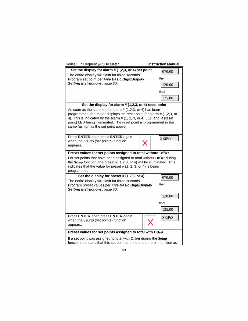
Series FIP Frequency/Pulse Meter Instruction Manual
59
Set the display for alarm # (1,2,3, or 4) set point
The entire display will flash for three seconds.Program set point per Five Basic Digit/DisplaySetting Instructions, page 30.
070.00
then
120.00
final
125.00
Set the display for alarm # (1,2,3, or 4) reset point
As soon as the set point for alarm # (1,2,3, or 4) has been
programmed, the meter displays the reset point for alarm # (1,2,3, or4). This is indicated by the alarm # (1, 2, 3, or 4) LED and R (resetpoint) LED being illuminated. The reset point is programmed in thesame fashion as the set point above.
Press ENTER, then press ENTER againwhen the SetPtS (set points) function
appears.
SEtPtS
Preset values for set points assigned to total without Offset
For set points that have been assigned to total without Offset during
the Setup function, the preset # (1,2,3, or 4) will be illuminated. Thisindicates that the value for preset # (1, 2, 3, or 4) is beingprogrammed.
Set the display for preset # (1,2,3, or 4)
The entire display will flash for three seconds.
Program preset values per Five Basic Digit/DisplaySetting Instructions, page 30.
070.00
then
120.00
final
125.00
Press ENTER, then press ENTER againwhen the SetPtS (set points) function
appears.
SEtPtS
Preset values for set points assigned to total with Offset
If a set point was assigned to total with Offset during the Setup
function, it means that this set point and the one before it function as

Series FIP Frequency/Pulse Meter Instruction Manual
60
a pair. That is, the first relay will always trip a specified number ofcounts before the second relay. This is called the preset offset valueand it is programmed as the first preset in a pair of set points set upfor Offset. The second value in a pair of set points set up for Offset
represents the actual preset value.
Set the display for preset offset and preset values
The entire display will flash for three seconds.Program presets per Five Basic Digit/DisplaySetting Instructions, page 30.
070.00
then
170.00
then
120.00
final
125.00

Series FIP Frequency/Pulse Meter Instruction Manual
61
Isolated 4-20 mA Output Programming (output)
Programming the 4-20 mA transmitter output option for the meter doesnot require the use of a calibrator. The transmitter output can becalibrated so that a 4 mA output is produced for any rate measured by
the meter. The 20 mA output may correspond to any rate that is at least501 counts greater or smaller than the rate corresponding to 4 mA. (Ex.4 mA = 0, 20 mA = 501) If the span between 4 and 20 mA is less than501 counts, an error message will appear and the previouslyprogrammed values will be retained in memory until a new set of values
is accepted.
Press ENTER, then press ENTER againwhen the Output menu appears
output
Set the display for value at which 4 mA isproduced
The green LED labeled “4” will be on indicating themeter is ready to accept the value at which 4 mA isproduced.
The entire display will flash for three seconds.Program display value corresponding to 4 mA outputper Five Basic Digit/Display Setting Instructions,page 30.
00000
final
00032
Set the display for value at which 20 mA isproduced
The green LED labeled “20” will now be on indicating
the meter is ready to accept the value at which 20mA is produced. Program this value in the samefashion as it was done above.
10000
final
01450
4-20 mA Output Programming ConfirmationThe values that have been programmed to produce the 4 and 20 mAoutputs can be quickly checked to make sure they are the desiredvalues. To do this, access the outPut routine by pressing ENTER, and
then pressing ENTER again when outPut appears. Note display valueswhen “4” and “20” LEDs are on and press ENTER before the displaystops flashing.

Series FIP Frequency/Pulse Meter Instruction Manual
62
Lockout and Display Selection Programming
Overview
The meter provides the user with the ability to restrict modification ofprogramming values and to exclude menu titles from appearing duringthe menu scroll. Restricting modification of the programming values isaccomplished by installing the lockout jumper (JP2). Excluding menutitles from the menu scroll is performed with the dSPLAy menu.
LockoutThe lockout jumper is used to restrict modification of calibration andprogramming values. It is labeled JP2, and it is located at the rear of theMain Board. When ENTER is pressed with the lockout jumper in place,SCale, CalIb, Cutoff, Tbase, Tot Cf, and dECPt do not appear during the
menu scroll, and thus cannot be modified.
FILtEr
SetPtS menu title always
appears. Ability to changevalues may be restricted.
outPut menu title appears
only if 4-20 mA outputoption is installed.
Figure 16. Functions Locked Out with Lockout JumperNotes:
1. The other function the lockout jumper performs is activatingselections made through the dSPLAy menu. That is, selectionsmade through the dSPLAy menu only become active when the
lockout jumper is installed.
2. With the lockout jumper in place, the SEtPtS menu still appears. To
program it so the set points, reset points or presets can only beviewed and not changed, it is necessary to set the SEtPtS menu inthe dSPLAy menu to n. To be able to change these values, set
SEtPtS menu in the dSPLAy menu to y.

Series FIP Frequency/Pulse Meter Instruction Manual
63
Display Selection (dSPLAy)
The display (dSPLAy) menu is used to remove menu titles fromappearing during the menu scroll. This feature is useful for eliminatingunused menu titles from the menu scroll, making it impossible toperform certain functions, and making the display automatically toggle
between rate and total.
For instance, the user may want to eliminate certain unused menu titlesfrom the scroll that do not relate to a particular application such as thoserelating to flow totalization. The dSPLAy menu could be used to
eliminate the rSEt t (reset total) and the dSPy t (display total) and thusstreamline the menu.
A supervisor may want to make it impossible for an operator to performcertain functions, but still allow himself to do them without having toremember passwords or remove a hard-to-get-at jumper. For instance,a supervisor could program the meter with the batch presets he wantsand disable the SEtPtS menu, thus making it impossible for a user to
change the batch presets by using the dSPLAy menu. When thesupervisor wants to change the batch presets, he can re-activate theSEtPtS menu and make his changes. Or a supervisor may want to make
it impossible for an operator to reset the total via the front panel, but stillallow himself to do it easily. This can be accomplished by removing therSEt t (reset total) menu title from the menu scroll, thus making it
impossible to reset the total via the front panel and then re-activating itwhen he wants to reset the total.
The user may want to make the display automatically toggle betweenrate and total. This can be accomplished by setting the dspy r (display
rate) and dspy t (display total) menus to n (no), as described below.
With the lockout jumper in place, the menu titles dspy r, dspy t, rset t,dspy p, setpts, dsplay, and, output can still be accessed. The 4-20 mA
output calibration points can be viewed, but cannot be modified.

Series FIP Frequency/Pulse Meter Instruction Manual
64
SetPtS menu title always appears.Ability to change values may be restricted.
Figure 17. Menu Titles Excluded with Dsplay MenuNotes:
1. The user may program which of these routine titles are active
during operation and which ones are not. See below forinstructions.
2. Selections made through the display menu can be made with orwithout the lockout jumper installed, but only become active whenthe lockout jumper is installed.
3. With the lockout jumper in place, the SEtPtS menu still appears. Toprogram it so the set points, reset points or presets can only beviewed and not changed, it is necessary to set the SEtPtS menu in
the dSPLAy menu to n. To be able to change these values, set
SEtPtS menu in the dSPLAy menu to y.

Series FIP Frequency/Pulse Meter Instruction Manual
65
Include or Exclude Menu Titles from Menu Scroll
Press ENTER, then press ENTER againwhen the Dsplay (display) function appears.
The meter will now scroll through thevarious menu titles that can be included orexcluded . To program a menu title, pressENTER when it appears.
Dsplay
Set menu scroll to include/exclude display rateDspy r (display rate) will appear for 3 seconds. PressENTER to set. Otherwise wait and meter moves on to
next menu title.
Dspy r
Y or N (yes or no) will flash alternately. To include
Dspy r in menu scroll, press ENTER when y isdisplayed. To exclude it, press ENTER when n is
displayed.
Y or n
Set menu scroll to include/excludedisplay total
Dspy t (display total) will appear for 3 seconds. PressENTER to set. Otherwise wait and meter moves on tonext menu title.
Dspy t
Y or N (yes or no) will flash alternately. To include
Dspy r in menu scroll, press ENTER when y isdisplayed. To exclude it, press ENTER when n is
displayed.
y or n
Set menu scroll to include/exclude reset total
Rset t (reset total) will appear for 3 seconds. PressENTER to set. Otherwise wait and meter moves on tonext menu title.
Rset t
Y or N (yes or no) will flash alternately. To includeDspy r in menu scroll, press ENTER when y is
displayed. to exclude it, press ENTER when n isdisplayed.
y or n
Set menu to include/exclude display peak
dspy p (display peak) will appear for 3 seconds. Press
ENTER to set it. Otherwise wait and meter moves onto next menu title.
Dspy p
Y or N (yes or no) will flash alternately. To include Dspy r in
menu scroll, press ENTER when y is displayed. To exclude
it, press ENTER when n is displayed.
y or n

Series FIP Frequency/Pulse Meter Instruction Manual
66
Set menu scroll to include/exclude set pointsSEtPtS
SEtPtS (set points) will appear for 3 seconds. Press
ENTER to set. Otherwise wait and meter moves on tonext menu title.
SEtPtS
Y or N (yes or no) will flash alternately. To include
SEtPtS in menu scroll, press ENTER when y isdisplayed. To exclude it, press ENTER when n is
displayed.
Y or n
Notes:
1. Select n for both dSPy r and dSPy t to program the display to toggle
between rate and total every 10 seconds.
2. Selecting y for SEtPtS will allow an operator to view and change
set/reset points and presets even with the lockout jumper in place.
3. Selecting n for SEtPtS will still allow an operator to view set/reset
points and presets, but will not allow making changes.
4. The total can be reset with an external push-button even if rSEt t isset to n.
Alternating DisplayThe display may be programmed to automatically toggle between rateand total every ten seconds. The alternating display is set up byselecting n (no) for both, dSPy r (display rate) and dSPy t (display total)
on the dSPLAy (display) menu.
Note: Selections made through the display menu can be made with orwithout the lockout jumper installed, but only become active when thelockout jumper is installed.
The Lockout jumper must be installed to see the alternating display orany other display selection made.
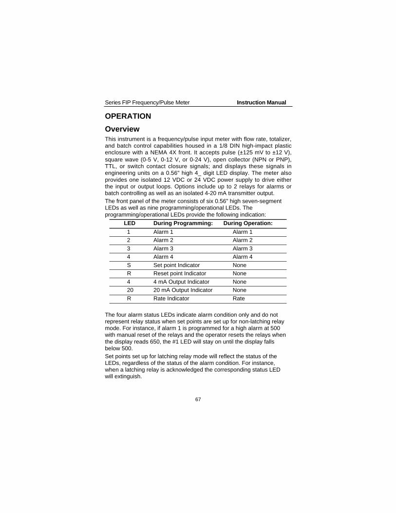
Series FIP Frequency/Pulse Meter Instruction Manual
67
OPERATION
Overview
This instrument is a frequency/pulse input meter with flow rate, totalizer,and batch control capabilities housed in a 1/8 DIN high-impact plasticenclosure with a NEMA 4X front. It accepts pulse (±125 mV to ±12 V),
square wave (0-5 V, 0-12 V, or 0-24 V), open collector (NPN or PNP),TTL, or switch contact closure signals; and displays these signals inengineering units on a 0.56" high 4_ digit LED display. The meter also
provides one isolated 12 VDC or 24 VDC power supply to drive eitherthe input or output loops. Options include up to 2 relays for alarms orbatch controlling as well as an isolated 4-20 mA transmitter output.
The front panel of the meter consists of six 0.56" high seven-segmentLEDs as well as nine programming/operational LEDs. The
programming/operational LEDs provide the following indication:
LED During Programming: During Operation:
1 Alarm 1 Alarm 1
2 Alarm 2 Alarm 2
3 Alarm 3 Alarm 3
4 Alarm 4 Alarm 4
S Set point Indicator None
R Reset point Indicator None
4 4 mA Output Indicator None
20 20 mA Output Indicator None
R Rate Indicator Rate
The four alarm status LEDs indicate alarm condition only and do notrepresent relay status when set points are set up for non-latching relaymode. For instance, if alarm 1 is programmed for a high alarm at 500with manual reset of the relays and the operator resets the relays when
the display reads 650, the #1 LED will stay on until the display fallsbelow 500.
Set points set up for latching relay mode will reflect the status of theLEDs, regardless of the status of the alarm condition. For instance,when a latching relay is acknowledged the corresponding status LEDwill extinguish.

Series FIP Frequency/Pulse Meter Instruction Manual
68
Two Types of Display: Rate and Total
The meter has the capability to display both rate and total. The operatormay toggle back and forth between flow rate and total automatically ormanually. When the meter is displaying rate, an LED labeled R on theright side of the front panel, illuminates to indicate this. There is no loss
of data while performing any of the programming or calibrationoperations; the meter continues working in the background even whenvalues are being reprogrammed.
ENTER ACK
751.2
Figure 18. Meter Displaying Process/Rate
ENTER ACK
Figure 19. Meter Displaying Total

Series FIP Frequency/Pulse Meter Instruction Manual
69
Basic Meter Operation
Overview
In its most basic form, the meter provides a digital display in engineeringunits of any frequency input signal. As a standard feature, the ACpowered meters provide the power to drive either the input or the4-20 mA output transmitter option.
ENTER and ACK Button Operation
In addition to programming the meter, the ENTER button is also used tooperate the meter.
The ACK button is used to acknowledge the relays during operation andto quit main menu scroll during programming, diagnostic menu, andcalibration.
The ENTER button performs the following operations with lockoutjumper installed:
Function Displayed Definition
DSPy r Display Rate Sets the rate as the default display
DSPy t Display Total Sets the total as the default display
RSEt t Reset Total Resets the totalizer to zero.
DSPy P Display Peak Displays the highest rate valuecaptured
Rset P Reset Peak Erases peak value from memoryand captures a new reading
Dsplay DisplaySelection
Activates or de-activates displayfunctions
DIA9 Diagnostic Displays parameter settings one ata time for diagnostic purposes.

Series FIP Frequency/Pulse Meter Instruction Manual
70
Display Peak & Reset Peak Operation (DSPy P & Rset P)
The meter captures the highest rate reading and displays it through thedspy p (display peak) function. The peak value may be reset using the
rset p (reset peak) function.
Display Peak (Hold) Reading
Press ENTER, then press ENTERagain when the DSPy P (display
peak) menu-title appears.
DSPy P
Meter displays peak reading
The meter is now displaying the peakreading as indicated by the flashinggreen R LED on the right side.
ENTER ACK
Reset Peak Reading
Press ENTER, then press ENTERagain when the Rset P (reset peak)
menu-title appears.
Rset P
Meter returns to displaying currentvalue
The meter is now displaying thecurrent value. The flashing green R
LED on the right side has stoppedflashing. ENTER ACK
751.2
Note:
While in the DSPy P (display peak) mode, the meter continues
capturing new peaks; but it does not respond to signals below thelast peak value captured; it remains “locked” on the peak displayreading. For instance, if while the meter is displaying a peak of 100,the input increases to 150, the new peak of 150 will be displayed. Ifthe input falls down to 125 before the peak display is reset, themeter will continue displaying 150 as the peak reading.

Series FIP Frequency/Pulse Meter Instruction Manual
71
Rate Meter Operation
Overview
The meter can also be used to display flow rate and is available with a
low-flow cutoff feature. Totalizer functions can be excluded from themenu scroll through the dsplay function, if the user is not interested intotal display.
Display Rate (dSPy r)
The user may toggle between a display of rate or total at any time.When displaying rate, the rate LED indicator will be illuminated. Tochange the display to rate:
To change the display from readingtotal to rate
Press ENTER to begin scrollingthrough the functions.
ENTER ACK
When dspy r (display rate)
appears, press ENTER.
ENTER ACK
dSPY r
The meter now displays rate and thegreen R LED on the right side is
illuminated.
ENTER ACK
Low-Flow Cutoff (CutoFF)
The low-flow cutoff feature allows the meter to be programmed so thatany input below the cutoff point is always displayed as zero on the ratedisplay.
In multi-point calibration/scaling, the total is based on the rate display;so, inputs below the low-flow cutoff value will not affect the totalizer.
In K-factor scaling, the totalizer ignores the low-flow cutoff; the totalizer
counts every incoming pulse regardless of the rate display.

Series FIP Frequency/Pulse Meter Instruction Manual
72
Totalizer Operation
Overview
The total is displayed on a six-digit display that is capable of reading to999,999. When the total exceeds 999,999, the display rolls over andbegins counting from zero again without loosing counts. The total canbe reset at any time via the front panel, via an external switch closure,or when the meter reaches the highest preset value.
In multi-point calibration/scaling, the meter calculates the total based onrate display and field programmable total conversion factor to displaytotal in engineering units. Time base must be selected according to timeunits in which rate is displayed.
In K-factor scaling, the meter calculates the total based on the inputpulses, K-factor value, and total conversion factor.
Display Total (dSPy t)
The user may toggle between a display of rate or total at any time.When displaying rate, the rate LED indicator will be illuminated.
To change the display from reading rateto total
The meter is now displaying rate, as
indicated by the green "R" LED illuminatedon the right side of the display. PressENTER to begin scrolling through thefunctions.
ENTER ACK
50.25
When dspy t (display total)
appears, press ENTER.
ENTER ACK
dSPY t
The meter now displays total.
ENTER ACK
45657
Total Conversion Factor (tot CF) and Time Base (t bASE)
The total conversion factor is a number that is multiplied by the rate tocompute the total. Time base is available in seconds, minutes, andhours.

Series FIP Frequency/Pulse Meter Instruction Manual
73
Applications Using Conversion Factor and Time BaseThe following tables illustrate the effect various total conversion factorsand time bases have on the operation of the meter:
Application 1
Rate Time
Base
Total
Conv.Factor
Total after
onesecond
Total after
one minute
Total
after onehour
Total
after oneday
60GPM
min 1 gal 1 gal 60 gal 360 gal 8640 gal
In the above application, a total conversion factor of 1 with a rate of 60GPM results in a total of 60 gallons after 1 minute.
Application 2
Rate Time
Base
Total
Conv.Factor
Total after
onesecond
Total after
oneminute
Total
after one
hour
Total
after oneday
60GPM
min 0.2 0.2 can 12 cans 720 cans 17280cans
In the above application, 5-gallon paint cans are being filled and theuser wants to keep track of the number of cans that have been filled, notthe total gallons of paint that has been dispensed.
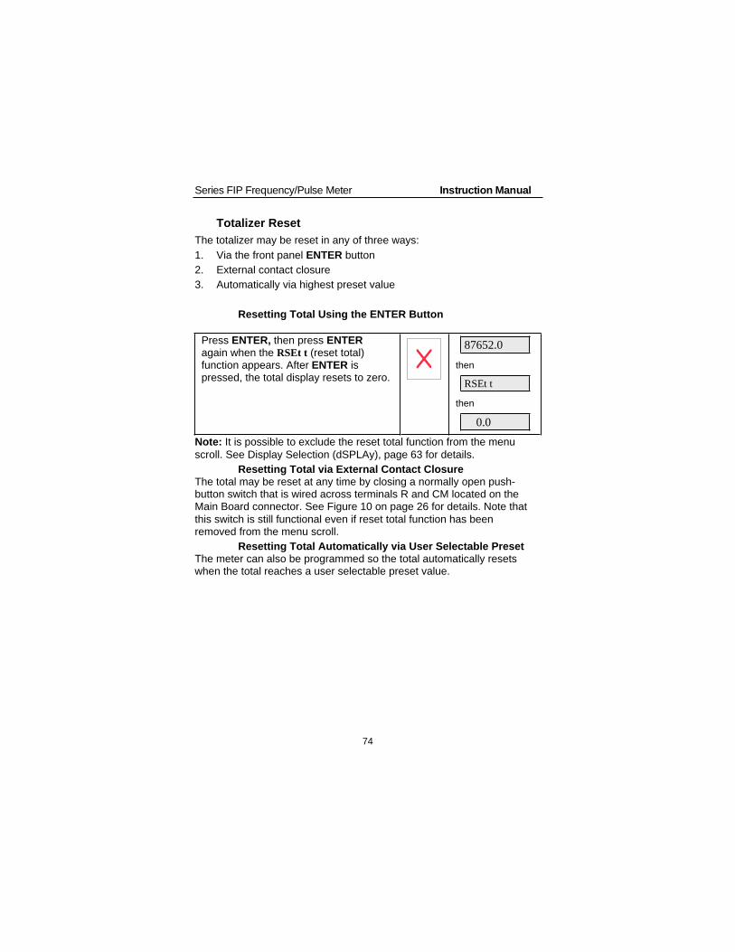
Series FIP Frequency/Pulse Meter Instruction Manual
74
Totalizer Reset
The totalizer may be reset in any of three ways:
1. Via the front panel ENTER button
2. External contact closure
3. Automatically via highest preset value
Resetting Total Using the ENTER Button
Press ENTER, then press ENTERagain when the RSEt t (reset total)function appears. After ENTER ispressed, the total display resets to zero.
87652.0
then
RSEt t
then
0.0
Note: It is possible to exclude the reset total function from the menu
scroll. See Display Selection (dSPLAy), page 63 for details.
Resetting Total via External Contact ClosureThe total may be reset at any time by closing a normally open push-button switch that is wired across terminals R and CM located on theMain Board connector. See Figure 10 on page 26 for details. Note that
this switch is still functional even if reset total function has beenremoved from the menu scroll.
Resetting Total Automatically via User Selectable PresetThe meter can also be programmed so the total automatically resetswhen the total reaches a user selectable preset value.

Series FIP Frequency/Pulse Meter Instruction Manual
75
Relays Operation
Overview
The relay capabilities of the meter expand its usefulness beyond simpleindication to provide users with alarm and control functions. Thesecapabilities include front panel alarm status LEDs as well as either 2optional relays. There are four basic ways the relays can be used:
1. High or Low Alarms
2. Simple On/Off Control with 100% Adjustable Deadband
3. Automatic Batch Control
4. Manual Batch Control
Relays Auto Initialization
When power is applied to the meter, the front panel LEDs and alarmrelays will reflect the state of the input to the meter. For instance, whenmeter is powered up, the following table indicates how the alarm LEDsand relays will react based on the various set and reset points:
Alarm#
HI or LO Set pointResetpoint
Power-upreading
Relay &LED
1 HI 1000 500 499 Off
2 LO 700 900 500 On
3 LO 250 400 500 Off
4 HI 450 200 500 On
Fail-Safe Operation
The following table indicates how the relays behave based on JumperJP6 being installed or not installed:
Jumper JP6 onDisplay Board
Fail-safe Relay coilsenergized in
Power failure
On Enabled Non-alarm state Relays go toalarm state
Off Disabled Alarm state Relays go tonon-alarm state

Series FIP Frequency/Pulse Meter Instruction Manual
76
Front Panel LEDs
The LEDs on the front panel provide status for the following:
LED Status LED Status
1 Alarm 1 S Set point Indicator
2 Alarm 2 R Reset point Indicator
3 Alarm 3 4 4 mA indicator
4 Alarm 4 20 20 mA indicator
R Rate indicator
The meter is supplied with four alarm points that include front panelLEDs to indicate alarm conditions. This standard feature is particularlyuseful for alarm applications that require visual-only indication. The frontpanel LEDs are controlled by the set and reset points programmed by
the user. When the display passes a set point for a particular alarm, thatalarm’s LED will light up. When the meter passes back through thatalarm’s reset point the LED will go off. The front panel LEDs responddifferently for latching and non-latching relays.
For non-latching relays, the LED is always off during normal condition
and always on during alarm condition, regardless of the state of therelay.
For latching relays, the alarm LEDs reflect the status of the relays,regardless of the alarm condition. The following tables illustrate how thealarm LEDs function in relation to the relays and the acknowledgebutton:
Latching and Non-Latching Relay Operation
Rate relays can be set up for latching or non-latching operation.
Relay key legend for following tables
Key Relay condition
On Tripped
Off Reset
Ack Acknowledged
The On and Off keys do not refer to the status of the relay’s coil, whichdepends on the fail-safe mode selected.

Series FIP Frequency/Pulse Meter Instruction Manual
77
Non-Latching Relay
Automatic reset only JP3(1-4 off)
Condition LED Relay
Normal Off Off
Alarm On On
Ack (No effect) On On
Normal Off Off
In this application, the meter is set up for automatic reset and non-latching relay. Acknowledging the alarm while it is still present has noeffect on either the LED or the relay. When the alarm finally goes away,the relay automatically resets and the LED also goes off.
Non-Latching Relay
Automatic + manual reset at any time JP3(1-4 on)
Condition LED Relay
Normal Off Off
Alarm On On
Normal Off Off
In this application, the meter is set up for automatic and manual reset atany time and non-latching relay. The LED and the relay automaticallyreset when the meter returned to the normal condition.
Automatic + manual reset at any time JP3(1-4 on)
Condition LED Relay
Normal Off Off
Alarm On On
Ack On Off
Normal Off Off
In this application, the meter is also set up for automatic and manual
reset at any time. But this time, an operator acknowledges the alarmmanually while it still exists. This causes the relay to reset, but the LEDstays on until the meter returns to the normal condition.Remember, for non-latching relays, the LED is always off during normalcondition and always on during alarm condition, regardless of the stateof the relay.

Series FIP Frequency/Pulse Meter Instruction Manual
78
Latching RelayManual reset only after signal passes reset point JP3(1-4 off)
Condition LED Relay
Normal Off Off
Alarm On On
Ack (No effect) On On
Normal On On
Ack Off Off
In this application, the meter is set up for manual reset only after thesignal passes the reset point of the latching relay. Acknowledging thealarm while it is still present has no effect on either the LED or the relay.When the alarm is acknowledged after it returns to the normal state, the
LED and the relay go off. Notice that the LED remained on, even afterthe meter returned to the normal condition. This is because, for latchingrelays, the alarm LEDs reflect the status of the relays, regardless of thealarm condition.
Manual reset only after signal passes reset point JP3(1-4 off)
Condition LED Relay
Normal Off Off
Alarm On On
Normal On On
Ack Off Off
In this application, the meter is set up for manual reset only after the
signal passes the reset point of the latching relay. When the alarm isacknowledged after it returns to the normal state, the LED and the relaygo off.
Manual reset any time JP3(1-4 on)
Condition LED Relay
Normal Off Off
Alarm On On
Ack Off Off
In this application, the meter is set up for Manual reset at any time.Acknowledging the alarm even if the alarm condition is still presentresets the relay and turns off the LED.

Series FIP Frequency/Pulse Meter Instruction Manual
79
Acknowledging Relays
There are two ways to acknowledge relays programmed for manual
reset: via the front panel ACK button and remotely via a switch wiredacross AK and CM terminals on the Main Board. When the ACK buttonor a switch wired across the AK and CM terminals is closed, all relaysprogrammed for manual reset will reset.
The total display is not affected by this action and therefore pressing the
ACK button or closing the acknowledge switch will not reset the total.
Delay on Release (delay)
The meter can be programmed so that when the highest preset value isreached the total automatically resets to zero (Automatic Batch Control).A delay on release can be programmed to reset the total relays after thedelay has elapsed. The delay can be programmed between 1 and 999seconds.
Example: Under the setup menu, relay 1 and 2 are assigned to total,OFFSET is not selected, internal total reset (I) is selected and a delay of
60 second is programmed. Under SEtPtS menu, the preset values areprogrammed as follows:
Set 1 (preset 1): 1000
Set 2 (preset 2): 2000
When the total reaches 1000, relay 1 transfers. The total keepsincreasing until it reaches 2000; at that moment, relay 2 transfers, thetotal resets to zero automatically, delay on released starts. Then 60seconds later relays 1 and 2 reset automatically and are ready to start anew batch.
Priority Batch Programming or Quick Presets
For some batch control applications it may be necessary to change thepresets frequently. The meter has a Quick Preset change feature thatallows all presets to be changed without entering the programmingroutine.
To change presets without entering the programming routine press andhold the ENTER button for more than 3 seconds. The meter will goimmediately to the first preset; the user can now program all presets.After the last preset has been programmed the meter returns to readingthe rate or total.
It is recommended to disable the process while changing presets.

Series FIP Frequency/Pulse Meter Instruction Manual
80
Switching Inductive Loads
The meter has the ability to suppress electrical noise generated byswitching inductive loads. However installing resistor-capacitor (RC)networks improves performance and prolongs the life of the meter’srelay contacts. This suppression can be obtained with RC networksassembled by the user or purchased as complete assemblies. Refer to
the following circuits for RC network assembly and installation:
Switching AC and DC Loads
Figure 20. AC and DC Loads Protection
Choose R and C as follows
R: 0.5 to 1 for each volt across the contacts
C: 0.5 to 1 F for each amp through closed contacts
Notes:
1. Use capacitors rated for 240 VAC.
2. RC networks may affect load release time of solenoid loads, check toconfirm proper operation.
3. Install the RC network at the meter's relay screw terminals. An RC networkmay also be installed across the load. Experiment for best results.
Switching Low Voltage DC Loads
Figure 21. Low Voltage DC Loads Protection
Use a diode with a reversebreakdown voltage two tothree times the circuit
voltage and forward currentat least as large as the loadcurrent.

Series FIP Frequency/Pulse Meter Instruction Manual
81
Lockout and Display Selection Operation
Overview
The meter provides the user with the ability to restrict modification of
programming values and to exclude menu titles from appearing duringthe menu scroll. Restricting modification of the programming values isaccomplished by installing the lockout jumper JP2. Excluding menutitles from the menu scroll is performed with the display menu.
Low Voltage Detector
The meter has a circuit, which monitors the line voltage. To protectagainst data loss the meter will shut down, after saving the total, whenthe voltage falls below specifications.
At power up the display normally flashes a test display of 188888 for afew seconds. If the line voltage is below specifications the meter willflash 18888L until the problem is corrected.
Diagnostic (dIA9) Feature
Overview
The diagnostic menu in the meter provides an easy way to view andwrite down the parameter settings. The information gathered throughthe diagnostic menu will be helpful to determine if a wrong setting iscausing the operation of the meter to be undesirable.
Operation
When the diagnostic menu is entered, the function and programmedparameters setting will be displayed one at a time. Press ENTER to stepthrough the functions and settings. If ENTER is not pressed within 10
seconds, the display will move to the next function or setting. To exit thediagnostic menu press the ACK button at any time.
Reset Meter to Factory Defaults
1. Remove the snap-off front cover, see page 82.
2. Using a pair of needle-nose pliers, short out the solder pads locatedon the top and bottom of the Main Board, to the right of the ACKbutton below JP6 (see Figure 2 on page 20), until the displayshows “reset”.
3. Press the ENTER button. The meter starts scrolling the menus.
4. Press the ACK button, at any time, to exit the menu scroll.

Series FIP Frequency/Pulse Meter Instruction Manual
82
OPTIONS CARD REMOVAL & INSTALLATION
Meter options are installed at the factory. It is NOT necessary to removethe circuit boards from the case to disable the relays’ fail-safe operation.The fail-safe jumper is located on the Display Board, see Figure 2 onpage 20. Refer to the following instructions and illustrations to remove
the snap-off cover and the circuit boards from the case.
Disconnect power prior to performing the followingoperations.
To remove the front cover from the case:
The meter's snap-off cover is held in place by 6 latches that snap into
notches on the snap-off cover. To remove the snap-off cover from themeter, grasp it firmly on its top and bottom edges and pull it forward.The latch plate remains around the meter's case.
To remove the circuit boards from the case:
1. Unscrew the retaining screws holding the circuit boards to the case.
2. Remove the screw terminal connectors at the rear of the meter.
3. Push the boards through the case by applying pressure to thecircuit boards at the rear of the meter. Apply pressure evenly toboth boards.
4. Do not apply pressure to the vertical Display Board.
Latch
Snap-offCover
Latch
Plate
Notch
Retaining Screws
and Washers
Figure 22. Front Cover Removal

Series FIP Frequency/Pulse Meter Instruction Manual
83
5. Jumper J2 on Options Board must NOT be installed on meters thathave the fail-safe jumper JP6 on the Display Board.
6. To avoid electric shock, re-install the circuit boards in the case priorto applying power.
All programming and calibrating can be performedwith the circuit boards installed in the case.
To re-install the meter in its case:
1. Fold the Options Board over the Main Board, grasp both boards sothe Main Board is on the bottom and the two Boards are separated
by about an inch.
2. Insert the two boards together into the case. Be sure both the topand bottom boards engage the rails, which hold them in place.
3. Do not press on the Display Board when seating the assembly inthe case.
4. Install washers and retaining screws in 4 corners of meter andinstall front cover.
Input Configuration
Jumpers
Display Board
Ribbon Cable
Transformer
Re
lays
J2
Screw Terminals (Rear)
Options Board
Not Installed
Figure 23. Options Card Installation

Series FIP Frequency/Pulse Meter Instruction Manual
84
PROGRAMMED PARAMETER SETTINGS
The following table shows the factory setting for most of theprogrammable parameters on the meter. Next to the factory setting,record the new setting for the particular application.
Model: ______________ S/N: _______________ Date: _________
Parameter Display FactorySetting
UserSetting
Input range 0-30,000 Hz
Type ofsignal
0-12V squarewave pulse
Calibrationmode
FActor 1.000
Filter HI Spd High speed filter
Total dec.point 999999
Rate decimalpoint 29999
Cutoff value CutOFF -199.99
Time base SEC Second
Low gate LO 1.0
High gate HI 3.0
Total conv.factor tot CF 1.000
Set pointsetup Set 1 Total
Set 2 Total
Set 3 Rate
Latchingrelay latCH Non-latching

Series FIP Frequency/Pulse Meter Instruction Manual
85
Parameter Display FactorySetting
UserSetting
Set 4 Rate
Latchingrelay latCH Non-latching
Total resetmode e rst
External
total reset
Set point Set 1 1000
Set 2 4000
Set 3 7000
(Reset 3) 6000
Set 4 9000
(Reset 4) 8000
4-20 mA out (4 mA) 00000
(20 mA) 10000
Displayselection dSPy r Yes
dSPy t Yes
rSEt t Yes
dspy p Yes
setpts No

Series FIP Frequency/Pulse Meter Instruction Manual
86
User Set point Setup and Programming Table
Parameter Display User Setting
Set point 1 SET 1
latCH
Set point 2 SET 2
latCH
OFFSEt
Set point 3 SET 3
latCH
OFFSEt
Set point 4 SET 4
latCH
OFFSEt
Total resetmode I or E
Delay onrelease delay
Set point 1 Set 1
Reset point 1 (Reset 1)
Set point 2 Set 2
Reset point 2 (Reset 2)
Set point 3 Set 3
Reset point 3 (Reset 3)
Set point 4 Set 4
Reset point 4 (Reset 4)

Series FIP Frequency/Pulse Meter Instruction Manual
87
MOUNTING DIMENSIONS
6" (152 mm) Clearance
4.25" (108 mm)
4.83" (123 mm)
Required for Installation
2.30"
(59 mm)
4.30" (109 mm)
Installed
0.575" (14.6 mm)
Panel Thickness
0.125" - 0.250" (3.2 - 6.4 mm)
Figure 24. Mounting Dimensions
3.622" (92 mm)
1.772"
(45 mm) Panel Cutout
to DIN 43700
Square Corners to 0.060"
(1.5 mm) Max Radius
A
B
Tolerances:
A: +0.032 (+0.8 mm)
-0.000 (-0.0 mm)
B: +0.024 (+0.6 mm)
-0.000 (-0.0 mm)
Figure 25. Panel Cutout DimensionsNotes:
1. Panel cutout required: 1.772" x 3.622" (45 mm x 92 mm) 1/8 DIN
2. Panel thickness: 0.125" - 0.250" (3.2 mm - 6.4 mm)
3. Clearance: Allow 6" (152 mm) behind the panel

Series FIP Frequency/Pulse Meter Instruction Manual
NOTES
DWYER INSTRUMENTS, INC.P.O. BOX 373 • MICHIGAN CITY, INDIANA 46361, U.S.A
Phone: 219/879-8000Fax: 219/872-9057
www.dwyer-inst.come-mail: [email protected]
©Copyright 2006 Dwyer Instruments, Inc. Printed in U.S.A. 11/06 FR # R2-443476-10
MAINTENANCEUpon final installation of the Series FIP Pulse Input Flow Indicator, no routine maintenance isrequired. A periodic check of the system calibration is recommended. The Series FIP is not fieldserviceable and should be returned if repair is needed (field repair should not be attempted andmay void warranty). Be sure to include a brief description of the problem plus any relevantapplication notes. Contact customer service to receive a return goods authorization numberbefore shipping.


![Untitled-4 [] · Standard lamineret (8 meter / *4 meter) Neon lamineret - 5 meter Mat lamineret - 8 meter / **5 meter) Metallic lamineret - 8 meter Ulamineret - 8 meter Fleksibel](https://img.pdfslide.tips/doc/110x75/5f3a768af7b8e86a6437cff7/untitled-4-standard-lamineret-8-meter-4-meter-neon-lamineret-5-meter.jpg)