Embed Size (px)
Citation preview
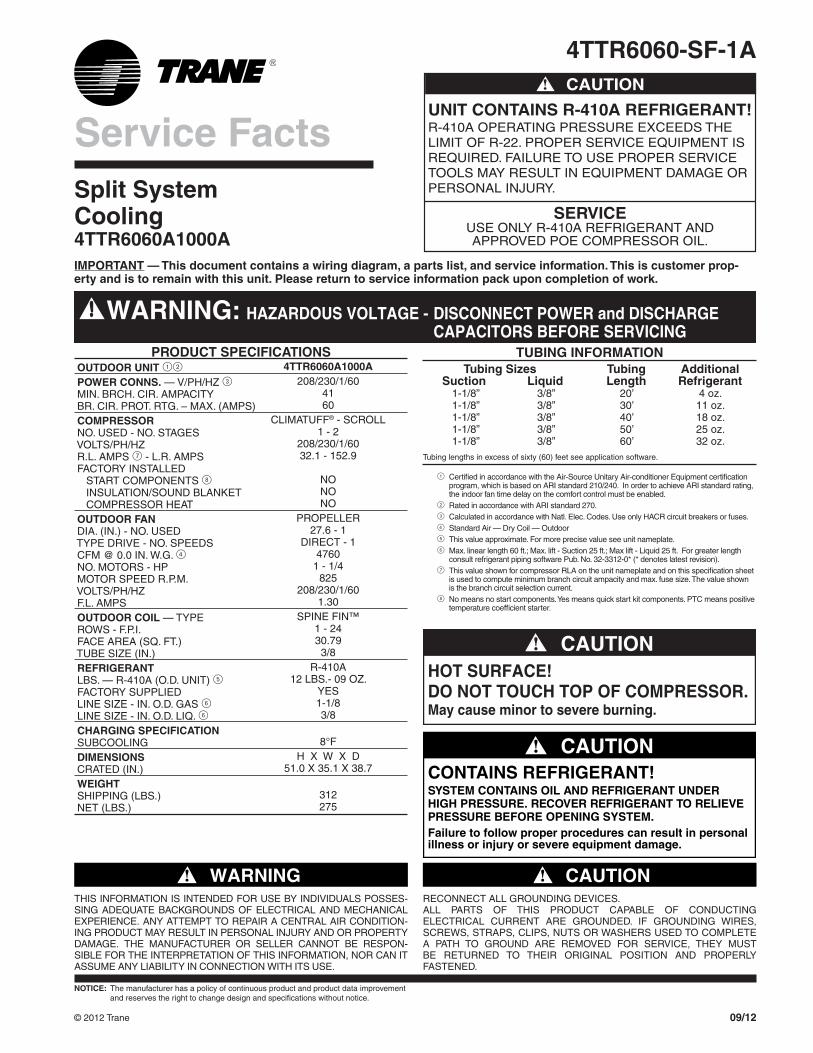
4TTR6060-SF-1A
Split SystemCooling4TTR6060A1000A
4TTR6060A1000A208/230/1/60
4160
CLIMATUFF® - SCROLL1 - 2
208/230/1/6032.1 - 152.9
NONONO
PROPELLER27.6 - 1
DIRECT - 14760
1 - 1/4825
208/230/1/601.30
SPINE FIN™1 - 2430.79
3/8R-410A
12 LBS.- 09 OZ.YES1-1/83/8
8°FH X W X D
51.0 X 35.1 X 38.7
312275
20’30’40’50’60’
1-1/8”1-1/8”1-1/8”1-1/8”1-1/8”
3/8”3/8”3/8”3/8”3/8”
4 oz.11 oz.18 oz.25 oz.32 oz.
TUBING INFORMATION Tubing Sizes Tubing Additional Suction Liquid Length Refrigerant
Tubing lengths in excess of sixty (60) feet see application software.
© 2012 Trane
IMPORTANT — This document contains a wiring diagram, a parts list, and service information. This is customer prop-erty and is to remain with this unit. Please return to service information pack upon completion of work.
PRODUCT SPECIFICATIONS OUTDOOR UNIT 12
POWER CONNS. — V/PH/HZ 3 MIN. BRCH. CIR. AMPACITY BR. CIR. PROT. RTG. – MAX. (AMPS) COMPRESSOR NO. USED - NO. STAGES VOLTS/PH/HZ R.L. AMPS 7 - L.R. AMPS FACTORY INSTALLED START COMPONENTS 8 INSULATION/SOUND BLANKET COMPRESSOR HEAT OUTDOOR FAN DIA. (IN.) - NO. USED TYPE DRIVE - NO. SPEEDS CFM @ 0.0 IN. W.G. 4 NO. MOTORS - HP MOTOR SPEED R.P.M. VOLTS/PH/HZ F.L. AMPS OUTDOOR COIL — TYPE ROWS - F.P.I. FACE AREA (SQ. FT.) TUBE SIZE (IN.) REFRIGERANT LBS. — R-410A (O.D. UNIT) 5 FACTORY SUPPLIED LINE SIZE - IN. O.D. GAS 6 LINE SIZE - IN. O.D. LIQ. 6 CHARGING SPECIFICATION SUBCOOLING DIMENSIONS CRATED (IN.) WEIGHT SHIPPING (LBS.) NET (LBS.)
Service Facts
NOTICE: The manufacturer has a policy of continuous product and product data improvement and reserves the right to change design and specifications without notice.
WARNING!THIS INFORMATION IS INTENDED FOR USE BY INDIVIDUALS POS SES-S ING ADEQUATE BACKGROUNDS OF ELECTRICAL AND MECHANICAL EXPERIENCE. ANY ATTEMPT TO REPAIR A CENTRAL AIR CONDITION-ING PRODUCT MAY RESULT IN PERSONAL INJURY AND OR PROPERTY DAMAGE. THE MANUFACTURER OR SELLER CANNOT BE RESPON-SIBLE FOR THE INTERPRETATION OF THIS INFORMATION, NOR CAN IT ASSUME ANY LIABILITY IN CONNECTION WITH ITS USE.
CAUTION!RECONNECT ALL GROUNDING DEVICES.ALL PARTS OF THIS PRODUCT CAPABLE OF CONDUCTING ELECTRICAL CURRENT ARE GROUNDED. IF GROUNDING WIRES, SCREWS, STRAPS, CLIPS, NUTS OR WASHERS USED TO COMPLETE A PATH TO GROUND ARE REMOVED FOR SERVICE, THEY MUST BE RETURNED TO THEIR ORIGINAL POSITION AND PROPERLY FASTENED.
WARNING: HAZARDOUS VOLTAGE - DISCONNECT POWER and DISCHARGE CAPACITORS BEFORE SERVICING
CAUTION!
UNIT CONTAINS R-410A REFRIGERANT!R-410A OPERATING PRESSURE EXCEEDS THE LIMIT OF R-22. PROPER SERVICE EQUIPMENT IS REQUIRED. FAILURE TO USE PROPER SERVICE TOOLS MAY RESULT IN EQUIPMENT DAMAGE OR PERSONAL INJURY.
SERVICEUSE ONLY R-410A REFRIGERANT ANDAPPROVED POE COMPRESSOR OIL.
09/12
1 Certified in accordance with the Air-Source Unitary Air-conditioner Equipment certification program, which is based on ARI standard 210/240. In order to achieve ARI standard rating, the indoor fan time delay on the comfort control must be enabled.
2 Rated in accordance with ARI standard 270.3 Calculated in accordance with Natl. Elec. Codes. Use only HACR circuit breakers or fuses.4 Standard Air — Dry Coil — Outdoor5 This value approximate. For more precise value see unit nameplate.6 Max. linear length 60 ft.; Max. lift - Suction 25 ft.; Max lift - Liquid 25 ft. For greater length
consult refrigerant piping software Pub. No. 32-3312-0* (* denotes latest revision).7 This value shown for compressor RLA on the unit nameplate and on this specification sheet
is used to compute minimum branch circuit ampacity and max. fuse size. The value shown is the branch circuit selection current.
8 No means no start components. Yes means quick start kit components. PTC means positive temperature coefficient starter.
CONTAINS REFRIGERANT!SYSTEM CONTAINS OIL AND REFRIGERANT UNDER HIGH PRESSURE. RECOVER REFRIGERANT TO RELIEVE PRESSURE BEFORE OPENING SYSTEM.Failure to follow proper procedures can result in personalillness or injury or severe equipment damage.
CAUTION!
HOT SURFACE!DO NOT TOUCH TOP OF COMPRESSOR.May cause minor to severe burning.
CAUTION!
4TTR6060-SF-1A2
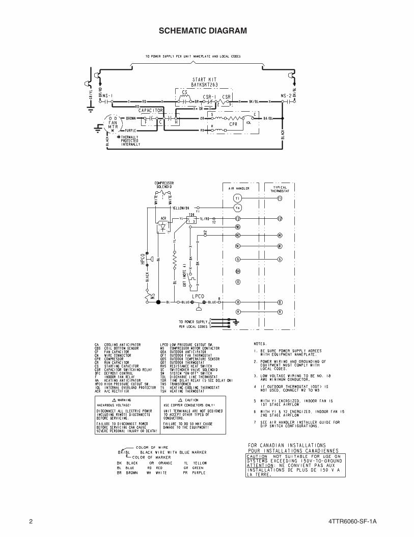
SCHEMATIC DIAGRAM
4TTR6060-SF-1A 3
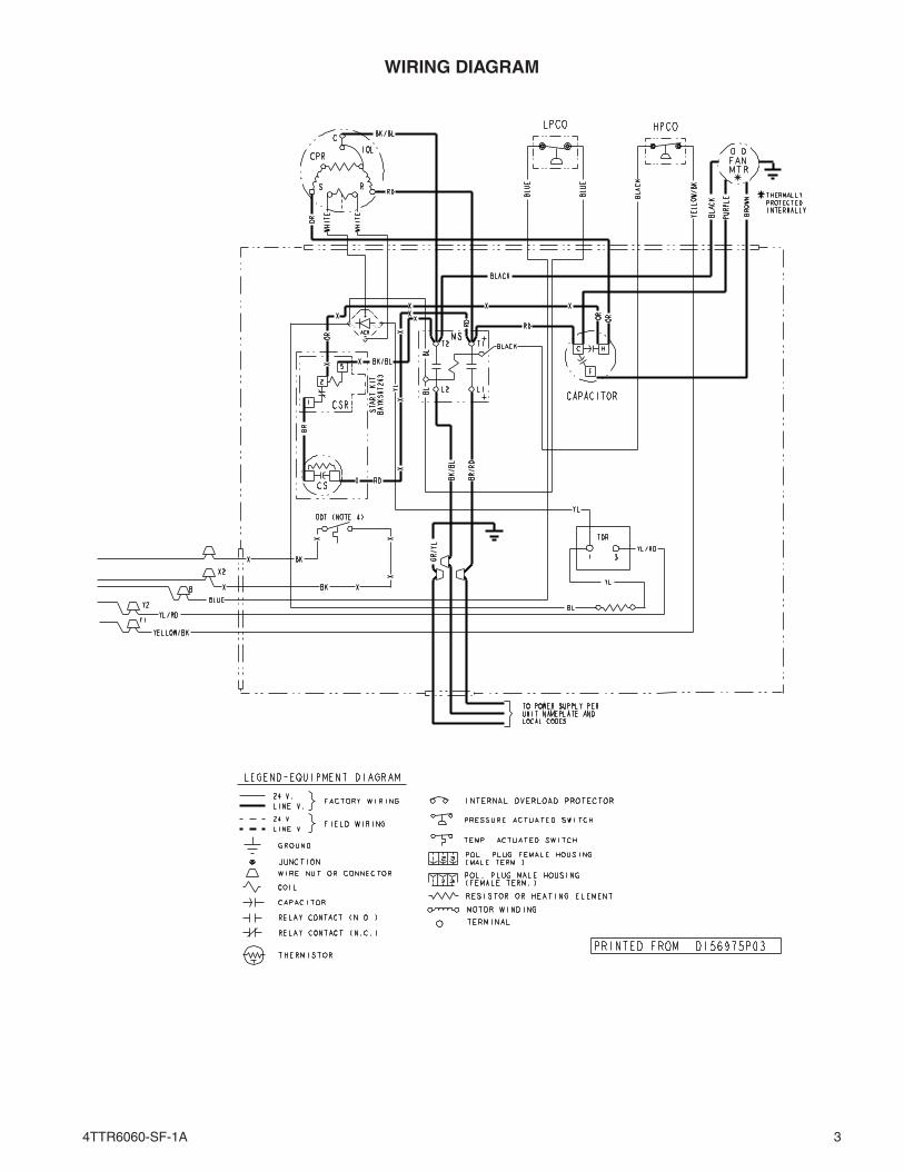
WIRING DIAGRAM
4TTR6060-SF-1A4
6050403025 Add 4º201510 Add 2º0
10 20 25 30 40 60RE
FR
IGE
RA
NT
LIN
E L
IFT
(F
T) SUBCOOL CHARGING CHART CORRECTIONS TABLE
TOTAL REFRIGERANT LINE LENGTH (FT)
Use Design Subcooling
Add 1º
Add 3º
25 ft. Maximum Lift
Add 2º
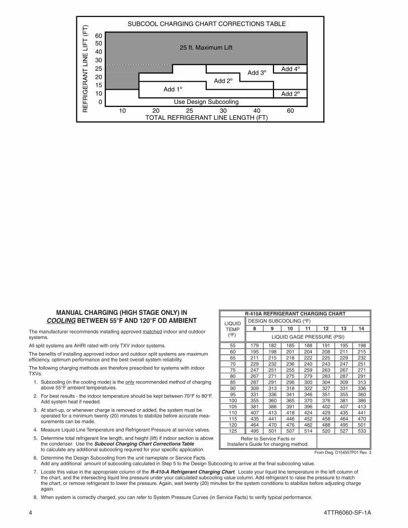
MANUAL CHARGING (HIGH STAGE ONLY) IN COOLING BETWEEN 55°F AND 120°F OD AMBIENT
The manufacturer recommends installing approved matched indoor and outdoor systems.
All split systems are AHRI rated with only TXV indoor systems.
The benefits of installing approved indoor and outdoor split systems are maximum efficiency, optimum performance and the best overall system reliability.
The following charging methods are therefore prescribed for systems with indoor TXVs.
1. Subcooling (in the cooling mode) is the only recommended method of charging above 55°F ambient temperatures.
2. For best results - the indoor temperature should be kept between 70°F to 80°F. Add system heat if needed.
3. At start-up, or whenever charge is removed or added, the system must be operated for a minimum twenty (20) minutes to stabilize before accurate mea-surements can be made.
4. Measure Liquid Line Temperature and Refrigerant Pressure at service valves.
5. Determine total refrigerant line length, and height (lift) if indoor section is above the condenser. Use the Subcool Charging Chart Corrections Table to calculate any additional subcooling required for your specific application.
6. Determine the Design Subcooling from the unit nameplate or Service Facts. Add any additional amount of subcooling calculated in Step 5 to the Design Subcooling to arrive at the final subcooling value.
7. Locate this value in the appropriate column of the R-410-A Refrigerant Charging Chart. Locate your liquid line temperature in the left column of the chart, and the intersecting liquid line pressure under your calculated subcooling value column. Add refrigerant to raise the pressure to match the chart, or remove refrigerant to lower the pressure. Again, wait twenty (20) minutes for the system conditions to stabilize before adjusting charge again.
8. When system is correctly charged, you can refer to System Pressure Curves (in Service Facts) to verify typical performance.
8 9 10 11 12 13 14
55 179 182 185 188 191 195 19860 195 198 201 204 208 211 21565 211 215 218 222 225 229 23270 229 232 236 240 243 247 25175 247 251 255 259 263 267 27180 267 271 275 279 283 287 29185 287 291 296 300 304 309 31390 309 313 318 322 327 331 33695 331 336 341 346 351 355 360100 355 360 365 370 376 381 386105 381 386 391 396 402 407 413110 407 413 418 424 429 435 441115 435 441 446 452 458 464 470120 464 470 476 482 488 495 501125 495 501 507 514 520 527 533
R-410A REFRIGERANT CHARGING CHART
Refer to Service Facts or Installer's Guide for charging method.
LIQUIDTEMP(°F)
DESIGN SUBCOOLING (°F)
LIQUID GAGE PRESSURE (PSI)
From Dwg. D154557P01 Rev. 3
4TTR6060-SF-1A
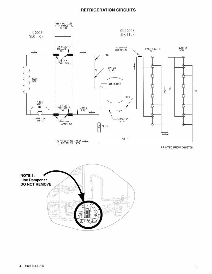
PRINTED FROM D156708
L I N E D A M P E N E R( S E E N O T E 1 )
NOTE 1:Line DampenerDO NOT REMOVE
5
REFRIGERATION CIRCUITS
4TTR6060-SF-1A6
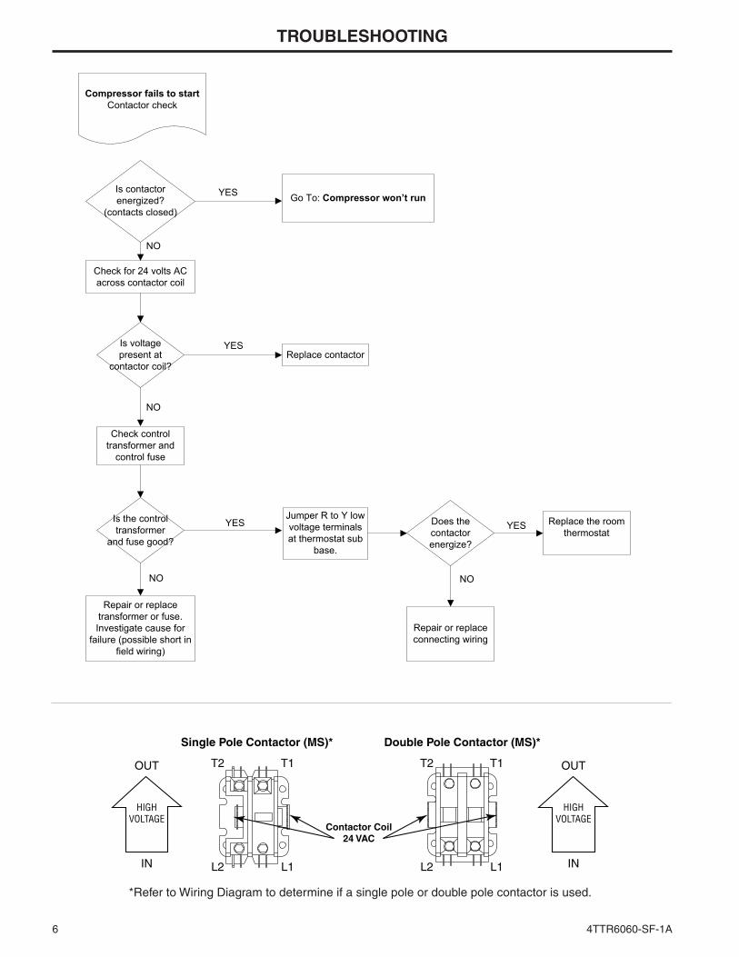
TROUBLESHOOTING
Is contactor energized?
(contacts closed)
Is voltage present at
contactor coil? Replace contactor
YES
NO
NO
Check for 24 volts AC across contactor coil
Check control transformer and
control fuse
Is the control transformer
and fuse good?
NO
YES
Repair or replace transformer or fuse. Investigate cause for
failure (possible short in field wiring)
Jumper R to Y low voltage terminals at thermostat sub
base.
Does the contactor energize?
NO
Repair or replace connecting wiring
YES Go To: Compressor won’t run
Replace the room thermostat
YES
Compressor fails to startContactor check
L2 L1
T2 T1
IN
OUT
L2 L1
T2 T1
Single Pole Contactor (MS)* Double Pole Contactor (MS)*
Contactor Coil 24 VAC
HIGHVOLTAGE
IN
OUT
HIGHVOLTAGE
*Refer to Wiring Diagram to determine if a single pole or double pole contactor is used.
4TTR6060-SF-1A 7
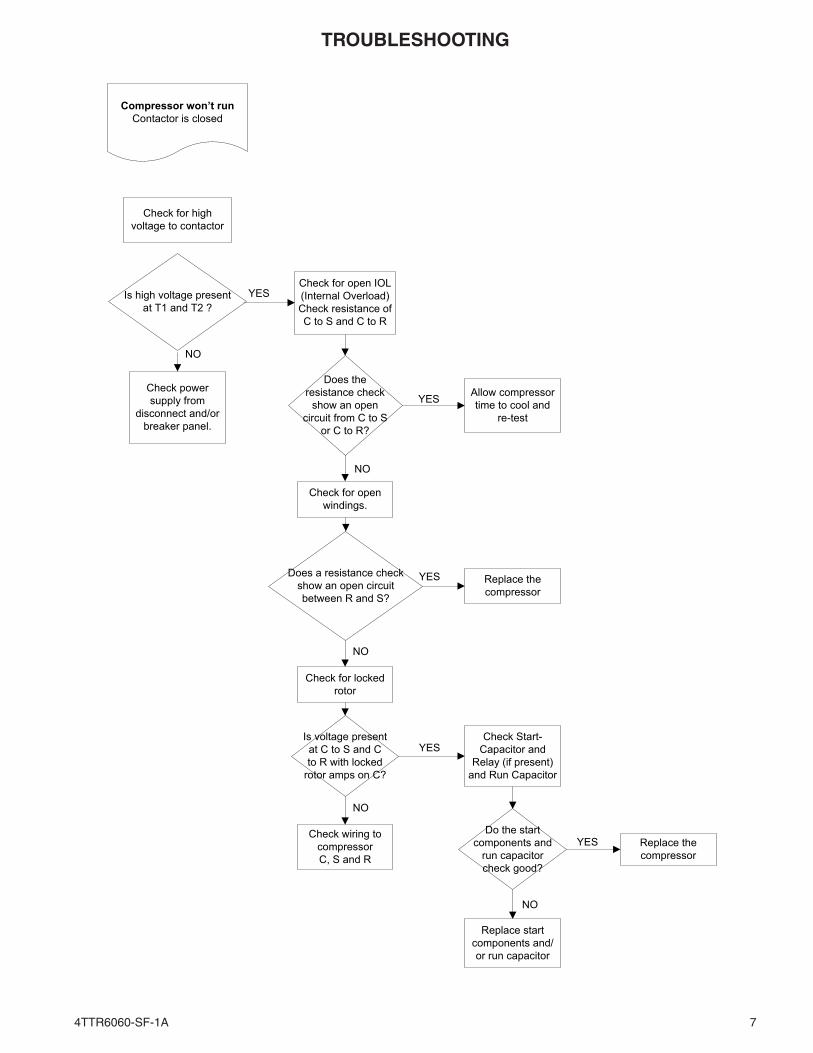
TROUBLESHOOTING
Check for open IOL (Internal Overload) Check resistance of C to S and C to R
Does the resistance check
show an open circuit from C to S
or C to R?
YES Allow compressor time to cool and
re-test
NO
Check for open windings.
YESDoes a resistance check show an open circuit between R and S?
Replace the compressor
NO
Check for locked rotor
Is voltage present at C to S and C to R with locked
rotor amps on C?
YESCheck Start-
Capacitor and Relay (if present)
and Run Capacitor
Do the start components and
run capacitor check good?
YES Replace the compressor
NO
Replace start components and/or run capacitor
NO
Check wiring to compressor C, S and R
Check for high voltage to contactor
Is high voltage present at T1 and T2 ?
YES
NO
Check power supply from
disconnect and/or breaker panel.
Compressor won’t runContactor is closed
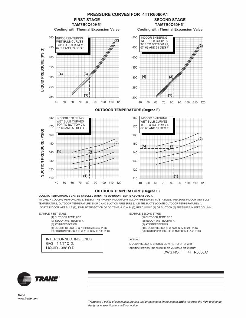
PRESSURE CURVES FOR 4TTR6060A1FIRST STAGE SECOND STAGE
TAM7B0C60H51 TAM7B0C60H51Cooling with Thermal Expansion Valve Cooling with Thermal Expansion Valve
LIQ
UID
PR
ESSU
RE
(PSI
G)
OUTDOOR TEMPERATURE (Degree F)
SUC
TIO
N P
RES
SUR
E (P
SIG
)
OUTDOOR TEMPERATURE (Degree F)COOLING PERFORMANCE CAN BE CHECKED WHEN THE OUTDOOR TEMP IS ABOVE 65 DEG F.TO CHECK COOLING PERFORMANCE, SELECT THE PROPER INDOOR CFM, ALLOW PRESSURES TO STABILIZE. MEASURE INDOOR WET BULB TEMPERATURE, OUTDOOR TEMPERATURE, LIQUID AND SUCTION PRESSURES. ON THE PLOTS LOCATE OUTDOOR TEMPERATURE (1); LOCATE INDOOR WET BULB (2); FIND INTERSECTION OF OD TEMP. & ID W.B. (3); READ LIQUID (4) OR SUCTION (5) PRESSURE IN LEFT COLUMN .
EXAMPLE: FIRST STAGE EXAMPLE: SECOND STAGE (1) OUTDOOR TEMP. 82 F. (1) OUTDOOR TEMP. 82 F. (2) INDOOR WET BULB 67 F. (2) INDOOR WET BULB 67 F. (3) AT INTERSECTION (3) AT INTERSECTION (4) LIQUID PRESSURE @ 1160 CFM IS 307 PSIG (4) LIQUID PRESSURE @ 1515 CFM IS 289 PSIG (5) SUCTION PRESSURE @ 1160 CFM IS 138 PSIG (5) SUCTION PRESSURE @ 1515 CFM IS 145 PSIG
INTERCONNECTING LINES ACTUAL:
GAS - 1 1/8" O.D. LIQUID PRESSURE SHOULD BE +/- 10 PSI OF CHART
LIQUID - 3/8" O.D. SUCTION PRESSURE SHOULD BE +/- 3 PSIG OF CHART
DWG.NO. 4TTR6060A1
110
120
130
140
150
160
170
180
40 50 60 70 80 90 100 110 120
110
120
130
140
150
160
170
180
40 50 60 70 80 90 100 110 120
200
250
300
350
400
450
500
40 50 60 70 80 90 100 110 120200
250
300
350
400
450
500
40 50 60 70 80 90 100 110 120
(1)
(1)
(3)
(3)
(5)
(4)
(2)
(2)
INDOOR ENTERING WET BULB CURVESTOP TO BOTTOM 71, 67, 63 AND 59 DEG F.
INDOOR ENTERING WET BULB CURVESTOP TO BOTTOM 71, 67, 63 AND 59 DEG F.
INDOOR ENTERING WET BULB CURVESTOP TO BOTTOM 71, 67, 63 AND 59 DEG F.
INDOOR ENTERING WET BULB CURVESTOP TO BOTTOM 71, 67, 63 AND 59 DEG F.
(2)
(1)
(4) (3)
(2)
(1)
(3)(5)
Tranewww.trane.com
Trane has a policy of continuous product and product data improvement and it reserves the right to change design and specifications without notice.