Embed Size (px)
Citation preview

Inverter-controlled multi system typeModels
SERVICE MANUAL
CONTENTS
1. TECHNICAL CHANGES ····································22. PART NAMES AND FUNCTIONS······················63. INDOOR UNIT OPERATIONAL CHARACTERISTICS····74. SPECIFICATION···············································185. OUTLINES AND DIMENSIONS ·······················216. WIRING DIAGRAM ··········································257. REFRIGERANT SYSTEM DIAGRAM··············308. DATA·································································369. ACTUATOR CONTROL····································52
10. SERVICE FUNCTIONS·····································5211. TROUBLESHOOTING······································5412. DISASSEMBLY INSTRUCTIONS·····················7113. PARTS LIST······················································8014. RoHS PARTS LIST···········································8815. OPTIONAL PARTS·········································100
No. OB444REVISED EDITION-C
The Slim Line.From Mitsubishi Electric.
TM
OUTDOOR UNIT
MXZ-2A20NAMXZ-2A20NA -MXZ-3A30NAMXZ-3A30NA -MXZ-4A36NA
1
1
MXZ-2A20NAMXZ-2A20NA - 1
Indoor unit service manualMSZ-A·NA Series (OB450)
Revision C:• MXZ-4A36NA have been added.
NOTE:• This service manual describes technical
data of the outdoor units.• RoHS compliant products have <G> mark
on the spec name plate. For servicing of RoHS compliant products,refer to the RoHS Parts List.
Please void OB444 REVISED EDITION-B.SPLIT-TYPE, HEAT PUMP AIR CONDITIONERS
HFCutilized
R410A
332239700058
OB444C--1.qxp 07.10.18 2:17 PM Page 1

TECHNICAL CHANGES
2
1
MXZ-2A20NANew model
MXZ-30TN2 MXZ-3A30NA1. Combinations of connectable indoor units have been increased.2. Capacity class of connectable indoor units have been made larger.3. Compressor has been changed. (THV247FBA TNB220FMCH)4. Outdoor fan motor has been changed. (RA6N60-AA RC0J60-AB)5. Refrigerant has been changed. (R22 R410A)6. Refrigerant system diagram has been changed.
• 1 of 2 high pressure switch has been removed.• Accumulator has been removed.• Receiver has been added.
7. Communication system has been changed.8. Power supply way has been changed(change to supply to outdoor unit). 9. Evaporation temperature thermistor has been added.
10. Ambient temperature thermistor has been added.
MXZ-2A20NA MXZ-2A20NA - 1. Compressor has been changed. (SNB130FPDH1 SNB130FQBH1)2. Gas pipe temperature thermistor has been removed.3. Pre-heat control has been added.4. Electronic control P.C. board has been changed. 5. Power board has been changed.
MXZ-3A30NA MXZ-3A30NA - 1. Ball valve has been changed to stop valve.2. Gas pipe temperature thermistor has been removed.3. Pre-heat control has been added.4. Auto line correcting function has been added.5. Noise filter P.C. board has been changed.6. Electronic control P.C. board has been changed.7. Weight has been changed. (158lb. 148lb.)
MXZ-4A36NANew model
1
1
Revision A:• RoHS PARTS LIST has been added.
Revision B:• MXZ-2A20NA - and MXZ-3A30NA - have been added.11
Revision C:• MXZ-4A36NA has been added.
OB444C--1.qxp 07.10.18 2:17 PM Page 2

3
INFORMATION FOR THE AIR CONDITIONER WITH R410A REFRIGERANT• This room air conditioner adopts HFC refrigerant (R410A) which never destroys the ozone layer.• Pay particular attention to the following points, though the basic installation procedure is same as that for R22 air
conditioners.1As R410A has working pressure approximate 1.6 times as high as that of R22, some special tools and piping parts/
materials are required. Refer to the table below.2Take sufficient care not to allow water and other contaminations to enter the R410A refrigerant during storage and
installation, since it is more susceptible to contaminations than R22.3For refrigerant piping, use clean, pressure-proof parts/materials specifically designed for R410A. (Refer to 2. Refrigerant
piping.)4Composition change may occur in R410A since it is a mixed refrigerant. When charging, charge liquid refrigerant to prevent
composition change.
Refri
gera
tion
oilR
efrig
eran
t
New refrigerantR410A
HFC-32: HFC-125 (50%:50%)Pseudo-azeotropic refrigerant
Not includedA1/A172.6-60.5
225.823.995
Non combustible0
1730From liquid phase in cylinder
PossibleIncompatible oil
NonNon
Previous refrigerantR22
R22 (100%)Single refrigerant
IncludedA1
86.5-41.4
136.342.772
Non combustible0.0551700
Gas phasePossible
Compatible oilLight yellow
Non
RefrigerantComposition (Ratio)Refrigerant handlingChlorineSafety group (ASHRAE)Molecular weightBoiling point (-F)Steam pressure [77-F](PSIG)Saturated steam density [77-F](lb/ft3)CombustibilityODP w1GWP w2Refrigerant charge methodAdditional charge on leakageKindColorSmell
w1 :Ozone Depletion Potential : based on CFC-11w2 :Global Warming Potential : based on CO2
OB444C--1.qxp 07.10.18 2:17 PM Page 3

4
R410A tools Can R22 tools be used?
Gas leak detector
R410A has high pressures beyond the measurement range of existing gauges.
Hose material has been changed to improve the pressure resistance.
Dedicated for HFC refrigerant.
1/4in. and 3/8in.
Description
Clamp bar hole has been enlarged to reinforce the spring strength in the tool.
Provided for flaring work (to be used with R22 flare tool).Provided to prevent the back flow of oil. This adapter enables you to use vacuum pumps.It is difficult to measure R410A with a charging cylinder because the refrigerant bubbles due to high pressure and high-speed vaporization.
No
No
No
Yes
Yes
New
New
New
Gauge manifold
Charge hose
Torque wrench
Flare tool
Flare gaugeVacuum pumpadapter
Electronic scale forrefrigerant charging
No : Not Substitutable for R410A Yes : Substitutable for R410A
No 1/2in. and 5/8in.
1.Tools dedicated for the air conditioner with R410A refrigerantThe following tools are required for R410A refrigerant. Some R22 tools can be substituted for R410A tools.
New Specification Current Specification
The incompatible refrigeration oil easily separates from refrigerant and is in the upper layer inside the suction muffler.Raising position of the oil back hole enables to back the refrigeration oil of the upper layer to flow back to the compressor.
Since refrigerant and refrigeration oil are compatible, refrigeration oil goes back to the compressor through the lower position oil back hole.
Compressor
Suction muffler
Oil back hole
Refrigeration oil
Refrigerant
Compressor
Suction muffler
Oil back hole
Refrigeration oil /Refrigerant
Com
pres
sor
-22 -4 14 32 50 68 86 104 122 140-73
0
73
145
218
290
363
435
508
580(PSIG)
R410A
R22
Conversion chart of refrigerant temperature and pressure
Sat
urat
ed li
quid
pre
ssur
e
(-F)
OB444C--1.qxp 07.10.18 2:17 PM Page 4

5
R410A
Pipe diameter(inch)
1/4
3/8
1/2
5/8
17 [11/16]
22 [7/8]
26 [1-1/32]
29 [1-5/32]
Dimension of flare nut
R22
(mm) [inch]
17 [11/16]
22 [7/8]
24 [15/16]
27 [1-1/16]
2Flaring work and flare nutFlaring work for R410A pipe differs from that for R22 pipe.For details of flaring work, refer to installation manual “FLARING WORK”.
3.Refrigeration oilApply the special refrigeration oil (accessories: packed with indoor unit) to the flare and the union seat surfaces.
4.Air purge• Do not discharge the refrigerant into the atmosphere.
Take care not to discharge refrigerant into the atmosphere during installation, reinstallation, or repairs to the refrigerant circuit.
• Use the vacuum pump for air purging for the purpose of environmental protection.
5.Additional chargeFor additional charging, charge the refrigerant from liquid phase of the gas cylinder. If the refrigerant is charged from the gas phase, composition change may occur in the refrigerant inside the cylinder and theoutdoor unit. In this case, ability of the refrigeration cycle decreases or normal operation can be impossible. However, charging the liquid refrigerant all at once may cause the compressor to be locked. Thus, charge the refrigerant slowly.
2.Refrigerant piping1Specifications
Use the copper or copper-alloy seamless pipes for refrigerant that meet the following specifications.
Wall thickness (inch)
Outside diameter(inch)
1/4
3/8
1/2
5/8
0.0315
0.0315
0.0315
0.0394
Heat resisting foam plastic
Specific gravity 0.045 Thickness 0.315 inch
Insulation material
Electronic scale for refrigerant charging
Outdoor unit
Refrigerant gas cylinderoperating valve
Refrigerant gas cylinderfor R410A with siphon
Refrigerant (liquid)
Service port
Gauge manifold valve (for R410A)
Union
Liquid pipe
Gas pipe
Stop valve
Indoor unit
Charge hose (for R410A)
OB444C--1.qxp 07.10.18 2:17 PM Page 5

6
MXZ-3A30NA
Air inlet
Drain outlet
(Back and side)
Air outlet
Air inlet
Drain outlet
(Back and side)
Air outlet
MXZ-3A30NA - MXZ-4A36NA1
Air outlet
Drain outlet
Air inlet(Back and side)
OB444C--1.qxp 07.10.18 2:17 PM Page 6
7
1
09
12
15
09+09
09+12
09+15
12+12
95
95
95
97
97
97
97
3.34
4.53
7.05
7.80
9.64
9.64
9.64
3.69
5.01
7.79
8.62
10.66
10.66
10.66
–
–
–
9,000
11,500
12,500
10,000
9,000(5,400 ~ 9,000)
12,000(5,400 ~ 12,000)
15,000(5,400 ~ 15,000)
18,000(7,800 ~ 18,000)
20,000(7,800 ~ 20,000)
20,000(7,800 ~ 20,000)
20,000(7,800 ~ 20,000)
730(490 ~ 730)
990( 490 ~ 990)
1,540(490 ~ 1,540)
1,740(630 ~ 1,740)
2,150(630 ~ 2,150)
2,150(630 ~ 2,150)
2,150(630 ~ 2,150)
9,000
12,000
15,000
9,000
8,500
7,500
10,000
Indoor unitscombination Unit A Unit B
Cooling capacity (BTU/h)
TotalPower consumption
(W)
Current(A)
Powerfactor(%)208V 230V
MXZ-2A20NA MXZ-2A20NA -
09
12
15
09+09
09+12
09+15
12+12
95
95
95
97
97
97
97
4.30
5.40
7.87
8.16
7.98
7.98
7.98
4.76
5.97
8.70
9.02
8.82
8.82
8.82
–
–
–
10,900
12,500
13,750
11,000
10,900(5,200 ~ 15,400)
13,600(5,200 ~ 16,400)
18,000(5,200 ~ 21,100)
21,800(8,500 ~ 21,800)
22,000(8,500 ~ 22,000)
22,000(8,500 ~ 22,000)
22,000(8,500 ~ 22,000)
940(480 ~ 1,430)
1,180(480 ~1,460)
1,720(480 ~ 2,100)
1,820(520 ~ 1,820)
1,780(520 ~ 1,780)
1,780(520 ~ 1,780)
1,780(520 ~ 1,780)
10,900
13,600
18,000
10,900
9,500
8,250
11,000
Indoor unitscombination
Heating capacity (BTU/h)
TotalPower consumption
(W)
Current(A)
Powerfactor(%)208V 230V
Unit A Unit B
OB444C--1.qxp 07.10.18 2:17 PM Page 7
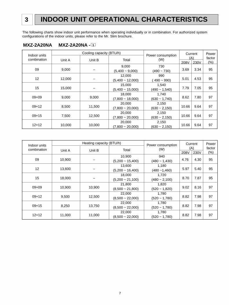
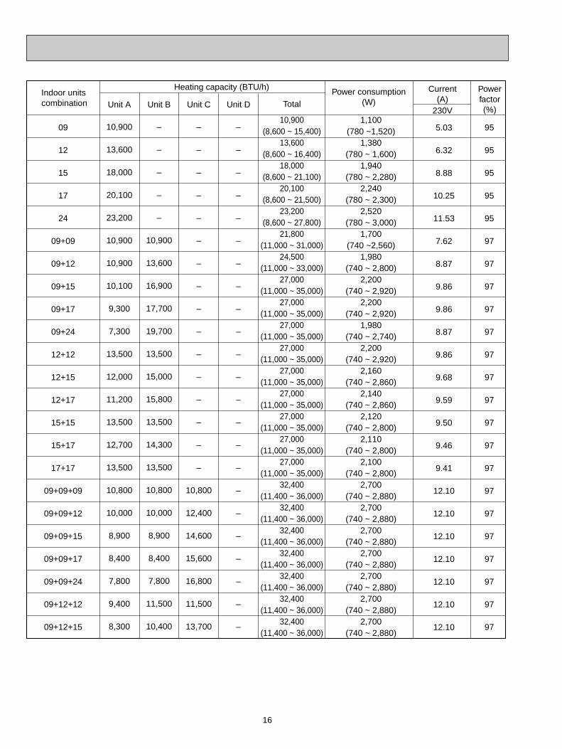
INDOOR UNIT OPERATIONAL CHARACTERISTICS
The following charts show indoor unit performance when operating individually or in combination. For authorized system configurations of the indoor units, please refer to the Mr. Slim brochure.
3

8
1
09
12
15
17
24
09+09
09+12
09+15
09+17
09+24
12+12
12+15
12+17
15+15
15+17
17+17
09+09+09
09+09+12
09+09+15
09+09+17
95
95
95
95
95
97
97
97
97
97
97
97
97
97
97
97
97
97
97
97
3.66
4.58
6.04
6.77
10.07
8.07
8.96
11.21
12.10
14.34
11.21
12.55
12.55
12.55
12.55
12.55
12.82
14.57
14.57
14.57
4.05
5.06
6.68
7.49
11.13
8.92
9.91
12.39
13.38
15.86
12.39
13.88
13.88
13.88
13.88
13.88
14.18
16.11
16.11
16.11
–
–
–
–
–
–
–
–
–
–
–
–
–
–
–
–
9,000
11,400
12,900
13,800
9,000(7,200 ~ 9,000)
12,000(7,200 ~ 12,000)
15,000(7,200 ~ 15,000)
16,200(7,200 ~ 16,200)
22,000(7,200 ~ 22,000)
18,000(12,000 ~ 18,000)
21,000(12,000 ~ 21,000)
24,000(12,000 ~ 24,000)
25,200(12,000 ~ 25,200)
28,000(12,000 ~ 28,000)
24,000(12,000 ~ 24,000)
26,000(12,000 ~ 26,000)
26,000(12,000 ~ 26,000)
26,000(12,000 ~ 26,000)
26,000(12,000 ~ 26,000)
26,000(12,000 ~ 26,000)
27,000(12,600 ~ 27,000)
28,400(12,600 ~ 28,400)
28,400(12,600 ~ 28,400)
28,400(12,600 ~ 28,400)
–
–
–
–
–
9,000
12,000
15,000
16,200
20,400
12,000
14,500
15,200
13,000
13,800
13,000
9,000
8,500
7,750
7,300
9,000
12,000
15,000
16,200
22,000
9,000
9,000
9,000
9,000
7,600
12,000
11,500
10,800
13,000
12,200
13,000
9,000
8,500
7,750
7,300
Indoor unitscombination Unit A Unit B Unit C
Cooling capacity (BTU/h)
TotalPower consumption
(W)
Current(A)
Powerfactor(%)208V 230V
MXZ-3A30NA MXZ-3A30NA -
800(650 ~ 800)
1,000(650 ~ 1,000)
1,320(650 ~ 1,320)
1,480(650 ~ 1,480)
2,220(650 ~ 2,200)
1,800(920 ~ 1,800)
2,000(920 ~ 2,000)
2,500(920 ~ 2,500)
2,700(920 ~ 2,700)
3,200(920 ~ 3,200)
2,500(920 ~ 2,500)
2,800(920 ~ 2,800)
2,800(920 ~ 2,800)
2,800(920 ~ 2,800)
2,800(920 ~ 2,800)
2,800(920 ~ 2,800)
2,860(1,000 ~ 2,850)
3,250(1,000 ~ 3,250)
3,250(1,000 ~ 3,250)
3,250(1,000 ~ 3,250)
OB444C--1.qxp 07.10.18 2:17 PM Page 8

9
09
12
15
17
24
09+09
09+12
09+15
09+17
09+24
12+12
12+15
12+17
15+15
15+17
17+17
09+09+09
09+09+12
09+09+15
09+09+17
95
95
95
95
95
97
97
97
97
97
97
97
97
97
97
97
97
97
97
97
5.03
6.32
8.88
10.25
11.53
7.62
8.87
9.86
9.86
8.87
9.86
9.68
9.59
9.50
9.46
9.41
9.77
9.77
9.77
9.77
5.57
6.98
9.82
11.34
12.75
8.43
9.81
10.90
10.90
9.81
10.90
10.71
10.61
10.51
10.46
10.41
10.80
10.80
10.80
10.80
Indoor unitscombination Unit A Unit B Unit C
Heating capacity (BTU/h)
TotalPower consumption
(W)
Current(A)
Powerfactor(%)208V 230V
–
–
–
–
–
–
–
–
–
–
–
–
–
–
–
–
9,500
11,400
13,000
13,900
10,900(8,600 ~ 15,400)
13,600(8,600 ~ 16,400)
18,000(8,600 ~ 21,100)
20,100(8,600 ~ 21,500)
23,200(8,600 ~ 27,800)
21,800(11,000 ~ 31,000)
24,500(11,000 ~ 33,000)
27,000(11,000 ~ 35,000)
27,000(11,000 ~ 35,000)
27,000(11,000 ~ 35,000)
27,000(11,000 ~ 35,000)
27,000(11,000 ~ 35,000)
27,000(11,000 ~ 35,000)
27,000(11,000 ~ 35,000)
27,000(11,000 ~ 35,000)
27,000(11,000 ~ 35,000)
28,500(11,400 ~ 36,000)
28,600(11,400 ~ 36,000)
28,600(11,400 ~ 36,000)
28,600(11,400 ~ 36,000)
–
–
–
–
–
10,900
13,600
16,900
17,700
19,700
13,500
15,000
15,800
13,500
14,300
13,500
9,500
8,600
7,800
7,350
1,100(780 ~1,520)
1,380(780 ~ 1,600)
1,940(780 ~ 2,280)
2,240(780 ~ 2,300)
2,520(780 ~ 3,000)
1,700(740 ~2,560)
1,980(740 ~ 2,800)
2,200(740 ~ 2,920)
2,200(740 ~ 2,920)
1,980(740 ~ 2,740)
2,200(740 ~ 2,920)
2,160(740 ~ 2,860)
2,140(740 ~ 2,860)
2,120(740 ~ 2,800)
2,110(740 ~ 2,800)
2,100(740 ~ 2,800)
2,180(740 ~ 2,880)
2,180(740 ~ 2,880)
2,180(740 ~ 2,880)
2,180(740 ~ 2,880)
10,900
13,600
18,000
20,100
23,200
10,900
10,900
10,100
9,300
7,300
13,500
12,000
11,200
13,500
12,700
13,500
9,500
8,600
7,800
7,350
OB444C--1.qxp 07.10.18 2:17 PM Page 9

10
09
12
15
17
24
09+09
09+12
09+15
09+17
09+24
12+12
12+15
12+17
15+15
15+17
17+17
09+09+09
09+09+12
09+09+15
09+09+17
09+09+24
09+12+12
95
95
95
95
95
97
97
97
97
97
97
97
97
97
97
97
97
97
97
97
97
97
4.05
5.06
6.68
7.49
11.13
8.92
9.91
12.39
13.38
15.86
12.39
13.88
13.88
13.88
13.88
13.88
14.18
16.21
17.35
17.35
17.35
17.35
–
–
–
–
–
–
–
–
–
–
–
–
–
–
–
–
9,000
12,000
14,500
15,700
18,300
11,700
–
–
–
–
–
–
–
–
–
–
–
–
–
–
–
–
–
–
–
–
–
–
9,000(7,200 ~ 9,000)
12,000(7,200 ~ 12,000)
15,000(7,200 ~ 15,000)
16,200(7,200 ~ 16,200)
22,000(7,200 ~ 22,000)
18,000(12,000 ~ 18,000)
21,000(12,000 ~ 21,000)
24,000(12,000 ~ 24,000)
25,200(12,000 ~ 25,200)
28,000(12,000 ~ 28,000)
24,000(12,000 ~ 24,000)
26,000(12,000 ~ 26,000)
26,000(12,000 ~ 26,000)
26,000(12,000 ~ 26,000)
26,000(12,000 ~ 26,000)
26,000(12,000 ~ 26,000)
27,000(12,600 ~ 27,000)
30,000(12,600 ~ 30,000)
32,100(12,600 ~ 32,100)
32,100(12,600 ~ 32,100)
32,100(12,600 ~ 32,100)
32,100(12,600 ~ 32,100)
–
–
–
–
–
9,000
12,000
15,000
16,200
20,400
12,000
14,500
15,200
13,000
13,800
13,000
9,000
9,000
8,800
8,200
6,900
11,700
9,000
12,000
15,000
16,200
22,000
9,000
9,000
9,000
9,000
7,600
12,000
11,500
10,800
13,000
12,200
13,000
9,000
9,000
8,800
8,200
6,900
8,700
Indoor unitscombination Unit A Unit B Unit C Unit D
Cooling capacity (BTU/h)
TotalPower consumption
(W)
Current(A)
Powerfactor(%)208V
MXZ-4A36NA 208V
800(650 ~ 800)
1,000(650 ~ 1,000)
1,320(650 ~ 1,320)
1,480(650 ~ 1,480)
2,200(650 ~ 2,200)
1,800(920 ~ 1,800)
2,000(920 ~ 2,000)
2,500(920 ~ 2,500)
2,700(920 ~ 2,700)
3,200(920 ~ 3,200)
2,500(920 ~ 2,500)
2,800(920 ~ 2,800)
2,800(920 ~ 2,800)
2,800(920 ~ 2,800)
2,800(920 ~ 2,800)
2,800(920 ~ 2,800)
2,860(1,000 ~ 2,850)
3,270(1,000 ~ 3,270)
3,500(1,000 ~ 3,500)
3,500(1,000 ~ 3,500)
3,500(1,000 ~ 3,500)
3,500(1,000 ~ 3,500)
OB444C--1.qxp 07.10.23 10:42 AM Page 10

11
09+12+15
09+12+17
09+15+15
09+15+17
09+17+17
12+12+12
12+12+15
12+12+17
12+15+15
09+09+09+09
09+09+09+12
09+09+09+15
09+09+12+12
97
97
97
97
97
97
97
97
97
99
99
99
99
17.35
17.35
17.35
17.35
17.35
17.35
17.35
17.35
17.35
18.55
18.55
18.55
18.55
13,400
14,400
12,300
13,300
12,700
10,700
12,300
13,300
11,500
9,000
8,300
7,700
10,300
–
–
–
–
–
–
–
–
–
9,000
11,100
12,900
10,300
32,100(12,600 ~ 32,100)
32,100(12,600 ~ 32,100)
32,100(12,600 ~ 32,100)
32,100(12,600 ~ 32,100)
32,100(12,600 ~ 32,100)
32,100(12,600 ~ 32,100)
32,100(12,600 ~ 32,100)
32,100(12,600 ~ 32,100)
32,100(12,600 ~ 32,100)
36,000(12,600 ~ 36,400)
36,000(12,600 ~ 36,400)
36,000(12,600 ~ 36,400)
36,000(12,600 ~ 36,400)
10,700
10,100
12,300
11,700
12,700
10,700
9,900
9,400
11,500
9,000
8,300
7,700
7,700
8,000
7,600
7,500
7,100
6,700
10,700
9,900
9,400
9,100
9,000
8,300
7,700
7,700
Indoor unitscombination Unit A Unit B Unit C Unit D
Cooling capacity (BTU/h)
TotalPower consumption
(W)
Current(A)
Powerfactor(%)208V
3,500(1,000 ~ 3,500)
3,500(1,000 ~ 3,500)
3,500(1,000 ~ 3,500)
3,500(1,000 ~ 3,500)
3,500(1,000 ~ 3,500)
3,500(1,000 ~ 3,500)
3,500(1,000 ~ 3,500)
3,500(1,000 ~ 3,500)
3,500(1,000 ~ 3,500)
3,820(1,000 ~ 3,900)
3,820(1,000 ~ 3,900)
3,820(1,000 ~ 3,900)
3,820(1,000 ~ 3,900)
OB444C--1.qxp 07.10.18 2:17 PM Page 11

12
09
12
15
17
24
09+09
09+12
09+15
09+17
09+24
12+12
12+15
12+17
15+15
15+17
17+17
09+09+09
09+09+12
09+09+15
09+09+17
09+09+24
09+12+12
09+12+15
95
95
95
95
95
97
97
97
97
97
97
97
97
97
97
97
97
97
97
97
97
97
97
5.57
6.98
9.82
11.34
12.75
8.43
9.81
10.90
10.90
9.81
10.90
10.71
10.61
10.51
10.46
10.41
13.38
13.38
13.38
13.38
13.38
13.38
13.38
Indoor unitscombination Unit A Unit B Unit DUnit C
Heating capacity (BTU/h)
TotalPower consumption
(W)
Current(A)
Powerfactor(%)208V
–
–
–
–
–
–
–
–
–
–
–
–
–
–
–
–
10,800
12,400
14,600
15,600
16,800
11,500
13,700
–
–
–
–
–
–
–
–
–
–
–
–
–
–
–
–
–
–
–
–
–
–
–
10,900(8,600 ~ 15,400)
13,600(8,600 ~ 16,400)
18,000(8,600 ~ 21,100)
20,100(8,600 ~ 21,500)
23,200(8,600 ~ 27,800)
21,800(11,000 ~ 31,000)
24,500(11,000 ~ 33,000)
27,000(11,000 ~ 35,000)
27,000(11,000 ~ 35,000)
27,000(11,000 ~ 35,000)
27,000(11,000 ~ 35,000)
27,000(11,000 ~ 35,000)
27,000(11,000 ~ 35,000)
27,000(11,000 ~ 35,000)
27,000(11,000 ~ 35,000)
27,000(11,000 ~ 35,000)
32,400(11,400 ~ 36,000)
32,400(11,400 ~ 36,000)
32,400(11,400 ~ 36,000)
32,400(11,400 ~ 36,000)
32,400(11,400 ~ 36,000)
32,400(11,400 ~ 36,000)
32,400(11,400 ~ 36,000)
–
–
–
–
–
10,900
13,600
16,900
17,700
19,700
13,500
15,000
15,800
13,500
14,300
13,500
10,800
10,000
8,900
8,400
7,800
11,500
10,400
1,100(780 ~1,520)
1,380(780 ~ 1,600)
1,940(780 ~ 2,280)
2,240(780 ~ 2,300)
2,520(780 ~ 3,000)
1,700(740 ~2,560)
1,980(740 ~ 2,800)
2,200(740 ~ 2,920)
2,200(740 ~ 2,920)
1,980(740 ~ 2,740)
2,200(740 ~ 2,920)
2,160(740 ~ 2,860)
2,140(740 ~ 2,860)
2,120(740 ~ 2,800)
2,110(740 ~ 2,800)
2,100(740 ~ 2,800)
2,700(740 ~ 2,880)
2,700(740 ~ 2,880)
2,700(740 ~ 2,880)
2,700(740 ~ 2,880)
2,700(740 ~ 2,880)
2,700(740 ~ 2,880)
2,700(740 ~ 2,880)
10,900
13,600
18,000
20,100
23,200
10,900
10,900
10,100
9,300
7,300
13,500
12,000
11,200
13,500
12,700
13,500
10,800
10,000
8,900
8,400
7,800
9,400
8,300
OB444C--1.qxp 07.10.18 2:17 PM Page 12

13
09+12+17
09+15+15
09+15+17
09+17+17
12+12+12
12+12+15
12+12+17
12+15+15
09+09+09+09
09+09+09+12
09+09+09+15
09+09+12+12
97
97
97
97
97
97
97
97
99
99
99
99
13.38
13.38
13.38
13.38
13.38
13.38
13.38
13.38
15.05
15.05
15.05
15.05
Indoor unitscombination Unit A Unit B Unit DUnit C
Heating capacity (BTU/h)
TotalPower consumption
(W)
Current(A)
Powerfactor(%)208V
14,600
12,400
13,300
12,700
10,800
13,000
13,800
11,700
9,000
8,300
7,700
10,300
–
–
–
–
–
–
–
–
9,000
11,100
12,900
10,300
32,400(11,400 ~ 36,000)
32,400(11,400 ~ 36,000)
32,400(11,400 ~ 36,000)
32,400(11,400 ~ 36,000)
32,400(11,400 ~ 36,000)
32,400(11,400 ~ 36,000)
32,400(11,400 ~ 36,000)
32,400(11,400 ~ 36,000)
36,000(11,400 ~ 41,200)
36,000(11,400 ~ 41,200)
36,000(11,400 ~ 41,200)
36,000(11,400 ~ 41,200)
9,900
12,400
11,900
12,700
10,800
9,700
9,300
11,700
9,000
8,300
7,700
7,700
2,700(740 ~ 2,880)
2,700(740 ~ 2,880)
2,700(740 ~ 2,880)
2,700(740 ~ 2,880)
2,700(740 ~ 2,880)
2,700(740 ~ 2,880)
2,700(740 ~ 2,880)
2,700(740 ~ 2,880)
3,100(740 ~ 4,000)
3,100(740 ~ 4,000)
3,100(740 ~ 4,000)
3,100(740 ~ 4,000)
7,900
7,600
7,200
7,000
10,800
9,700
9,300
9,000
9,000
8,300
7,700
7,700
OB444C--1.qxp 07.10.18 2:17 PM Page 13

14
09
12
15
17
24
09+09
09+12
09+15
09+17
09+24
12+12
12+15
12+17
15+15
15+17
17+17
09+09+09
09+09+12
09+09+15
09+09+17
09+09+24
09+12+12
95
95
95
95
95
97
97
97
97
97
97
97
97
97
97
97
97
97
97
97
97
97
3.66
4.58
6.04
6.77
10.07
8.07
8.96
11.21
12.10
14.34
11.21
12.55
12.55
12.55
12.55
12.55
12.82
14.66
15.69
15.69
15.69
15.69
–
–
–
–
–
–
–
–
–
–
–
–
–
–
–
–
9,000
12,000
14,500
15,700
18,300
11,700
–
–
–
–
–
–
–
–
–
–
–
–
–
–
–
–
–
–
–
–
–
–
9,000(7,200 ~ 9,000)
12,000(7,200 ~ 12,000)
15,000(7,200 ~ 15,000)
16,200(7,200 ~ 16,200)
22,000(7,200 ~ 22,000)
18,000(12,000 ~ 18,000)
21,000(12,000 ~ 21,000)
24,000(12,000 ~ 24,000)
25,200(12,000 ~ 25,200)
28,000(12,000 ~ 28,000)
24,000(12,000 ~ 24,000)
26,000(12,000 ~ 26,000)
26,000(12,000 ~ 26,000)
26,000(12,000 ~ 26,000)
26,000(12,000 ~ 26,000)
26,000(12,000 ~ 26,000)
27,000(12,600 ~ 27,000)
30,000(12,600 ~ 30,000)
32,100(12,600 ~ 32,100)
32,100(12,600 ~ 32,100)
32,100(12,600 ~ 32,100)
32,100(12,600 ~ 32,100)
–
–
–
–
–
9,000
12,000
15,000
16,200
20,400
12,000
14,500
15,200
13,000
13,800
13,000
9,000
9,000
8,800
8,200
6,900
11,700
9,000
12,000
15,000
16,200
22,000
9,000
9,000
9,000
9,000
7,600
12,000
11,500
10,800
13,000
12,200
13,000
9,000
9,000
8,800
8,200
6,900
8,700
Indoor unitscombination Unit A Unit B Unit C Unit D
Cooling capacity (BTU/h)
TotalPower consumption
(W)
Current(A)
Powerfactor(%)230V
MXZ-4A36NA 230V
800(650 ~ 800)
1,000(650 ~ 1,000)
1,320(650 ~ 1,320)
1,480(650 ~ 1,480)
2,200(650 ~ 2,200)
1,800(920 ~ 1,800)
2,000(920 ~ 2,000)
2,500(920 ~ 2,500)
2,700(920 ~ 2,700)
3,200(920 ~ 3,200)
2,500(920 ~ 2,500)
2,800(920 ~ 2,800)
2,800(920 ~ 2,800)
2,800(920 ~ 2,800)
2,800(920 ~ 2,800)
2,800(920 ~ 2,800)
2,860(1,000 ~ 2,850)
3,270(1,000 ~ 3,270)
3,500(1,000 ~ 3,500)
3,500(1,000 ~ 3,500)
3,500(1,000 ~ 3,500)
3,500(1,000 ~ 3,500)
OB444C--1.qxp 07.10.23 10:42 AM Page 14

15
09+12+15
09+12+17
09+15+15
09+15+17
09+17+17
12+12+12
12+12+15
12+12+17
12+15+15
09+09+09+09
09+09+09+12
09+09+09+15
09+09+12+12
97
97
97
97
97
97
97
97
97
99
99
99
99
15.69
15.69
15.69
15.69
15.69
15.69
15.69
15.69
15.69
16.78
16.78
16.78
16.78
13,400
14,400
12,300
13,300
12,700
10,700
12,300
13,300
11,500
9,000
8,300
7,700
10,300
–
–
–
–
–
–
–
–
–
9,000
11,100
12,900
10,300
32,100(12,600 ~ 32,100)
32,100(12,600 ~ 32,100)
32,100(12,600 ~ 32,100)
32,100(12,600 ~ 32,100)
32,100(12,600 ~ 32,100)
32,100(12,600 ~ 32,100)
32,100(12,600 ~ 32,100)
32,100(12,600 ~ 32,100)
32,100(12,600 ~ 32,100)
36,000(12,600 ~ 36,400)
36,000(12,600 ~ 36,400)
36,000(12,600 ~ 36,400)
36,000(12,600 ~ 36,400)
10,700
10,100
12,300
11,700
12,700
10,700
9,900
9,400
11,500
9,000
8,300
7,700
7,700
8,000
7,600
7,500
7,100
6,700
10,700
9,900
9,400
9,100
9,000
8,300
7,700
7,700
Indoor unitscombination Unit A Unit B Unit C Unit D
Cooling capacity (BTU/h)
TotalPower consumption
(W)
Current(A)
Powerfactor(%)230V
3,500(1,000 ~ 3,500)
3,500(1,000 ~ 3,500)
3,500(1,000 ~ 3,500)
3,500(1,000 ~ 3,500)
3,500(1,000 ~ 3,500)
3,500(1,000 ~ 3,500)
3,500(1,000 ~ 3,500)
3,500(1,000 ~ 3,500)
3,500(1,000 ~ 3,500)
3,820(1,000 ~ 3,900)
3,820(1,000 ~ 3,900)
3,820(1,000 ~ 3,900)
3,820(1,000 ~ 3,900)
OB444C--1.qxp 07.10.18 2:18 PM Page 15
16
09
12
15
17
24
09+09
09+12
09+15
09+17
09+24
12+12
12+15
12+17
15+15
15+17
17+17
09+09+09
09+09+12
09+09+15
09+09+17
09+09+24
09+12+12
09+12+15
95
95
95
95
95
97
97
97
97
97
97
97
97
97
97
97
97
97
97
97
97
97
97
5.03
6.32
8.88
10.25
11.53
7.62
8.87
9.86
9.86
8.87
9.86
9.68
9.59
9.50
9.46
9.41
12.10
12.10
12.10
12.10
12.10
12.10
12.10
Indoor unitscombination Unit A Unit B Unit DUnit C
Heating capacity (BTU/h)
TotalPower consumption
(W)
Current(A)
Powerfactor(%)230V
–
–
–
–
–
–
–
–
–
–
–
–
–
–
–
–
10,800
12,400
14,600
15,600
16,800
11,500
13,700
–
–
–
–
–
–
–
–
–
–
–
–
–
–
–
–
–
–
–
–
–
–
–
10,900(8,600 ~ 15,400)
13,600(8,600 ~ 16,400)
18,000(8,600 ~ 21,100)
20,100(8,600 ~ 21,500)
23,200(8,600 ~ 27,800)
21,800(11,000 ~ 31,000)
24,500(11,000 ~ 33,000)
27,000(11,000 ~ 35,000)
27,000(11,000 ~ 35,000)
27,000(11,000 ~ 35,000)
27,000(11,000 ~ 35,000)
27,000(11,000 ~ 35,000)
27,000(11,000 ~ 35,000)
27,000(11,000 ~ 35,000)
27,000(11,000 ~ 35,000)
27,000(11,000 ~ 35,000)
32,400(11,400 ~ 36,000)
32,400(11,400 ~ 36,000)
32,400(11,400 ~ 36,000)
32,400(11,400 ~ 36,000)
32,400(11,400 ~ 36,000)
32,400(11,400 ~ 36,000)
32,400(11,400 ~ 36,000)
–
–
–
–
–
10,900
13,600
16,900
17,700
19,700
13,500
15,000
15,800
13,500
14,300
13,500
10,800
10,000
8,900
8,400
7,800
11,500
10,400
1,100(780 ~1,520)
1,380(780 ~ 1,600)
1,940(780 ~ 2,280)
2,240(780 ~ 2,300)
2,520(780 ~ 3,000)
1,700(740 ~2,560)
1,980(740 ~ 2,800)
2,200(740 ~ 2,920)
2,200(740 ~ 2,920)
1,980(740 ~ 2,740)
2,200(740 ~ 2,920)
2,160(740 ~ 2,860)
2,140(740 ~ 2,860)
2,120(740 ~ 2,800)
2,110(740 ~ 2,800)
2,100(740 ~ 2,800)
2,700(740 ~ 2,880)
2,700(740 ~ 2,880)
2,700(740 ~ 2,880)
2,700(740 ~ 2,880)
2,700(740 ~ 2,880)
2,700(740 ~ 2,880)
2,700(740 ~ 2,880)
10,900
13,600
18,000
20,100
23,200
10,900
10,900
10,100
9,300
7,300
13,500
12,000
11,200
13,500
12,700
13,500
10,800
10,000
8,900
8,400
7,800
9,400
8,300
OB444C--1.qxp 07.10.18 2:18 PM Page 16

17
09+12+17
09+15+15
09+15+17
09+17+17
12+12+12
12+12+15
12+12+17
12+15+15
09+09+09+09
09+09+09+12
09+09+09+15
09+09+12+12
97
97
97
97
97
97
97
97
99
99
99
99
12.10
12.10
12.10
12.10
12.10
12.10
12.10
12.10
13.61
13.61
13.61
13.61
Indoor unitscombination Unit A Unit B Unit DUnit C
Heating capacity (BTU/h)
TotalPower consumption
(W)
Current(A)
Powerfactor(%)230V
14,600
12,400
13,300
12,700
10,800
13,000
13,800
11,700
9,000
8,300
7,700
10,300
–
–
–
–
–
–
–
–
9,000
11,100
12,900
10,300
32,400(11,400 ~ 36,000)
32,400(11,400 ~ 36,000)
32,400(11,400 ~ 36,000)
32,400(11,400 ~ 36,000)
32,400(11,400 ~ 36,000)
32,400(11,400 ~ 36,000)
32,400(11,400 ~ 36,000)
32,400(11,400 ~ 36,000)
36,000(11,400 ~ 43,000)
36,000(11,400 ~ 43,000)
36,000(11,400 ~ 43,000)
36,000(11,400 ~ 43,000)
9,900
12,400
11,900
12,700
10,800
9,700
9,300
11,700
9,000
8,300
7,700
7,700
2,700(740 ~ 2,880)
2,700(740 ~ 2,880)
2,700(740 ~ 2,880)
2,700(740 ~ 2,880)
2,700(740 ~ 2,880)
2,700(740 ~ 2,880)
2,700(740 ~ 2,880)
2,700(740 ~ 2,880)
3,100(740 ~ 4,350)
3,100(740 ~ 4,350)
3,100(740 ~ 4,350)
3,100(740 ~ 4,350)
7,900
7,600
7,200
7,000
10,800
9,700
9,300
9,000
9,000
8,300
7,700
7,700
OB444C--1.qxp 07.10.18 2:18 PM Page 17

18
SPECIFICATION4
1
1
1
Item Model
Capacity
Powerconsumption
EER [SEER]HSPF IV (V)COPExternal finishPower supplyMax. fuse size (time delay)Min. circuit ampacityFan motor
Compressor
Refrigerant controlSound level Defrost method
Dimensions
WeightRemote controllerControl voltage (by built-in transformer)Refrigerant piping
Valve size
Connection method
Refrigerant charge (R410A)
Refrigeration oil (Model)
Model
Winding resistance (at 68˚F) "
WDH
LiquidGasIndoorOutdoor
Btu/hBtu/hBtu/h
WWW
V, phase, Hz AA
F.L.A
R.L.AL.R.A
dB(A)
in.in.in.lb.
in.in.
lb.
oz.
20,000/ (7,800 ~ 20,000)22,000/ (8,500 ~ 22,000)
14,5002,150/ (630 ~ 2,150)1,780/ (520 ~ 1,780)
1,500 (1,500)9.3 [15]9.0 (7.0)
3.63Munsell 5Y 8/1208/230, 1, 60
2015
0.96
U-V 0.45 V-W 0.45 W-U 0.45U-V 0.98 V-W 0.98 W-U 0.98
10.115
LEV49/51
Reverse cycle33-1/16
1327-15/16
130Wireless type12-24V DC
Not supplied (optional parts)1/4
A,B:3/8FlaredFlared
5lb. 15oz.
1 3
1
1
2
1
1
2
CoolingHeating 47Heating 17CoolingHeating 47Heating 17CoolingHeatingHeating
MXZ-2A20NA MXZ-2A20NA -
SNB130FPDH1SNB130FQBH1
20.3 (NEO22)23.7 (NEO22)
MXZ-2A20NAMXZ-2A20NA -
MXZ-2A20NAMXZ-2A20NA -
1
MXZ-2A20NAMXZ-2A20NA -
Cooling
Heating
Mode
1: "A" Cooling steady state at rated compressor speed3: "B-2" Cooling steady state at rated compressor speed "B-1" Cooling steady state at minimum compressor speed Low ambient cooling steady state at minimum compressor speedIntermediate cooling steady state at intermediate compressor speedw
1: Standard rating-heating at rated compressor speed 2: Low temperature heating at rated compressor speed Max. temperature heating at minimum compressor speedHigh temperature heating at minimum compressor speedFrost accumulation at rated compressor speedFrost accumulation at intermediate compressor speedw
TestIndoor air condition Outdoor air condition
Dry bulb Wet bulb Dry bulb Wet bulb
8080808080707070707070
6767676767606060606060
9582826787471762473535
(75)(65)(65)
(53.5)(69)4315
56.5433333
wAt intermediate compressor speed =("Cooling rated compressor speed" - "minimum compressor speed") / 3 + "minimum compressor speed".
Unit: ˚F
NOTE : Test conditions are based on ARI 210/240. 1 : Rating conditions (cooling) — Indoor : 80˚FDB, 67˚FWB, Outdoor : 95˚FDB, (75˚FWB)
(heating) — Indoor : 70˚FDB, 60˚FWB, Outdoor : 47˚FDB, 43˚FWB 2 : (heating) — Indoor : 70˚FDB, 60˚FWB, Outdoor : 17˚FDB, 15˚FWB 3 : (cooling) — Indoor : 80˚FDB, 67˚FWB, Outdoor : 82˚FDB, 65˚FWB
OB444C--1.qxp 07.10.23 10:13 AM Page 18

19
1
1
Item Model
Capacity
Powerconsumption
EER [SEER]HSPF IV (V)COPExternal finishPower supplyMax. fuse size (time delay)Min. circuit ampacityFan motor
Compressor
Refrigerant controlSound level Defrost method
Dimensions
Weight
Remote controllerControl voltage (by built-in transformer)Refrigerant piping
Valve size
Connection method
Refrigerant charge (R410A)Refrigeration oil (Model)
ModelWinding resistance (at 68˚F) "
WDH
LiquidGasIndoorOutdoor
Btu/hBtu/hBtu/h
WWW
V, phase, Hz AA
F.L.A
R.L.AL.R.A
dB(A)
in.in.in.
lb.
in.in.
lb.oz.
28,400/ (12,600 ~ 28,400)28,600/ (11,400 ~ 36,000)
18,8003,250/ (1,000 ~ 3,250)2,180/ (740 ~ 2,880)
2,1208.7 [16.0]10.0 (7.5)
3.84Munsell 3.0Y 7.8/1.1
208/230, 1, 602015
0.93TNB220FMCH
U-V 0.61 V-W 0.61 W-U 0.611115
LEV49/49
Reverse cycle35-7/16
12-19/3235-7/16
158148
Wireless type12-24V DC
Not supplied (optional parts)1/4
A:1/2 B,C:3/8FlaredFlared
7lb. 11oz.29.4 (NEO22)
1 3
1
1
2
1
1
2
CoolingHeating 47Heating 17CoolingHeating 47Heating 17CoolingHeatingHeating
MXZ-3A30NA MXZ-3A30NA -
MXZ-3A30NAMXZ-3A30NA -
Cooling
Heating
Mode
1: "A" Cooling steady state at rated compressor speed3: "B-2" Cooling steady state at rated compressor speed "B-1" Cooling steady state at minimum compressor speed Low ambient cooling steady state at minimum compressor speedIntermediate cooling steady state at intermediate compressor speedw
1: Standard rating-heating at rated compressor speed 2: Low temperature heating at rated compressor speed Max. temperature heating at minimum compressor speedHigh temperature heating at minimum compressor speedFrost accumulation at rated compressor speedFrost accumulation at intermediate compressor speedw
TestIndoor air condition Outdoor air condition
Dry bulb Wet bulb Dry bulb Wet bulb
8080808080707070707070
6767676767606060606060
9582826787471762473535
(75)(65)(65)
(53.5)(69)4315
56.5433333
wAt intermediate compressor speed =("Cooling rated compressor speed" - "minimum compressor speed") / 3 + "minimum compressor speed".
Unit: ˚F
NOTE : Test conditions are based on ARI 210/240. 1 : Rating conditions (cooling) — Indoor : 80˚FDB, 67˚FWB, Outdoor : 95˚FDB, (75˚FWB)
(heating) — Indoor : 70˚FDB, 60˚FWB, Outdoor : 47˚FDB, 43˚FWB 2 : (heating) — Indoor : 70˚FDB, 60˚FWB, Outdoor : 17˚FDB, 15˚FWB 3 : (cooling) — Indoor : 80˚FDB, 67˚FWB, Outdoor : 82˚FDB, 65˚FWB
OB444C--1.qxp 07.10.23 10:13 AM Page 19

20
Item
208V
208V
36,000/ (11,400 ~ 41,200)
3,100/ (740 ~ 4,000)
230V
230V
36,000/ (11,400 ~ 43,000)
3,100/ (740 ~ 4,350)
Model
Capacity
Powerconsumption
EER [SEER]HSPF IV (V)COPExternal finishPower supplyMax. fuse size (time delay)Min. circuit ampacityFan motor
Compressor
Refrigerant controlSound level Defrost method
Dimensions
WeightRemote controllerControl voltage (by built-in transformer)Refrigerant piping
Valve size
Connection method
Refrigerant charge (R410A)Refrigeration oil (Model)
ModelWinding resistance (at 68˚F) "
WDH
LiquidGasIndoorOutdoor
Btu/hBtu/hBtu/h
WWW
V, phase, Hz AA
F.L.A
R.L.AL.R.A
dB(A)
in.in.in.lb.
in.in.
lb.oz.
36,000/ (12,600 ~ 36,400)
24,6003,820/ (1,000 ~ 3,900)
3,3409.4 [16.0]9.5 (7.0)
3.40Munsell 3.0Y 7.8/1.1
208/230, 1, 602019
0.93TNB220FMCH
U-V 0.61 V-W 0.61 W-U 0.6114.415
LEV54/57
Reverse cycle35-7/16
12-19/3235-7/16
150Wireless type12-24V DC
Not supplied (optional parts)1/4
A:1/2 B,C,D:3/8FlaredFlared
8lb. 13oz.29.4 (NEO22)
1 3
1
1
2
1
1
2
CoolingHeating 47Heating 17CoolingHeating 47Heating 17CoolingHeatingHeating
MXZ-4A36NA
Cooling
Heating
Mode
1: "A" Cooling steady state at rated compressor speed3: "B-2" Cooling steady state at rated compressor speed "B-1" Cooling steady state at minimum compressor speed Low ambient cooling steady state at minimum compressor speedIntermediate cooling steady state at intermediate compressor speedw
1: Standard rating-heating at rated compressor speed 2: Low temperature heating at rated compressor speed Max. temperature heating at minimum compressor speedHigh temperature heating at minimum compressor speedFrost accumulation at rated compressor speedFrost accumulation at intermediate compressor speedw
TestIndoor air condition Outdoor air condition
Dry bulb Wet bulb Dry bulb Wet bulb
8080808080707070707070
6767676767606060606060
9582826787471762473535
(75)(65)(65)
(53.5)(69)4315
56.5433333
wAt intermediate compressor speed =("Cooling rated compressor speed" - "minimum compressor speed") / 3 + "minimum compressor speed".
Unit: ˚F
NOTE : Test conditions are based on ARI 210/240. 1 : Rating conditions (cooling) — Indoor : 80˚FDB, 67˚FWB, Outdoor : 95˚FDB, (75˚FWB)
(heating) — Indoor : 70˚FDB, 60˚FWB, Outdoor : 47˚FDB, 43˚FWB 2 : (heating) — Indoor : 70˚FDB, 60˚FWB, Outdoor : 17˚FDB, 15˚FWB 3 : (cooling) — Indoor : 80˚FDB, 67˚FWB, Outdoor : 82˚FDB, 65˚FWB
OB444C--1.qxp 07.10.23 10:13 AM Page 20

21
OUTLINES AND DIMENSIONS5
MXZ-2A20NA MXZ-2A20NA - 1
More than 3.94 in.
Open as a ruleMore than 19.69 in.if the front and both sides areopen
More than 3.94 in.More than 7.87 in.if there are obstacles to bothsides
Open as a ruleMore than 19.69 in. if the back, both sidesand top are open
More than 13.78 in.
Indoor and outdoorconnect wiring3-[7/8" hole
Drain hole 3-[1-5/16"
Air in
Air in
Air out
(Base bolt M10)4-13/32" 13/16" Oval hole
A unit connection
B unit connection
[3/8"flared (both A&B unit)Gas pipe
[1/4"flared (both A&B unit)Liquid pipe
6-9/16" 6-21/32"
1-3/
16"
1-3/
16"
12-3
/4"
14-3
/16"
11-3/4" 2-5/8"
1-25
/32"
15/16"
8-5/
8"
5-5/
16"
11/1
6"11
/16"
14-3
/16"
15-1
9/32
"
1-1/
2"1-
7/32
"
19-11/16"
11-11/32"9-3/16"
2-1/2"
1-7/
32"
21/3
2"
1/2"1-3/16" 13"
1"
1-3/16"33-1/16"
27-1
5/16
"
29/32"
Lock nut Connector
Grounding terminal
Conduitcover
Unit: inch
REQUIRED SPACE
OB444C--1.qxp 07.10.18 2:18 PM Page 21

22
MXZ-3A30NA
3-15/32"
29/3
2"
1-1/
4"
3-25
/32"
29-9
/16"
2-11/16"
15"
9-27
/32"
1-3/16"
35-7
/16"
1-5/
16"
(7-7/8")
(5/8
")
(1-1
/16"
)
13-3
1/32
"(5
/8")
15-1
/4"
1-9/
16"
12-19/32" 13/32"
7-7/8" 19-11/16"
35-7/16"
18-1
/8"
12-1/2"
1-31
/32"
29/32"
9-27/32" 10-5/8"1-3/8"
1-3/
8"2-
29/3
2"
Indoor and outdoorconnect wiring4-[7/8" hole
Gas pipe
[1/2" flared (A unit) [3/8" flared (B,C unit)
[1/4" flared Liquid pipe
C unit connection
B unit connection
A unit connection
Air in
Drain hole 3-[1-5/16"
Air out
Air in
(Base bolt M10)2-U-shape notched holes
(Base bolt M10)2-15/32"1-13/32" Oval hole
More than 3.94 in.
Open as a ruleMore than 19.69 in.if the front and both sides are open
More than 3.94 in.More than 7.87 in.if there areobstacles to bothsides
Open as a ruleMore than 19.69 in. if the back, both sidesand top are open
More than 13.78 in.
Unit: inch
Conduit cover
Lock nut
Connector
REQUIRED SPACE
OB444C--1.qxp 07.10.18 2:18 PM Page 22

23
MXZ-3A30NA - 1 Unit: inch
A
B
C
15/1
6"7/
16"
5/8"
5/8"
1-1/
16"
1-9/
16"
14"
15-1
/4"
10-5/8"9-27/32"
1-3/8"
19-11/16" 7-7/8"7-7/8"2-
29/3
2"
1-3/
8"
(Bol
t pitc
h)
Air in
Air out
Air in
2-(15/32"o1-13/32") Oval hole
2-U Shaped notched hole (Base bolt M10)
3-[7/8"Punched hole(Connect wiring hole)
35-7/16"
(Connect wiring hole)2-[7/8"Knockout
Handle
Handle8-
27/3
2"
1-25
/32"
19-1
/8"
12-1/2"
18-1
/8"
29/32"
13/32"12-19/32"1-3/16"
3-15/32"
Gas pipe [3/8 (B,C unit)[1/2 (A unit)
More than 3-15/16"
Mor
e th
an 1
9-11
/16"
Mor
e th
an 7
-7/8
"
More than13-25/32"
Mor
e th
an 3
-15/
16"
Mor
e th
an 1
9-11
/16"
More than 13-25/32"More than 13-25/32"
More than 3-15/16"
SERVICE SPACE
More than 3-15/16"
Mor
e th
an 1
9-11
/16"
5-3/
16"
Liquid pipe [1/4 flared
35-7
/16"
1-3/
16"
4-3/
4"
(Base bolt M10)
Drain hole 3-[1-5/16"
Note : Leave front and both sides clearance fully.
Note : Leave front and overhead clearance fully.
Note : Leave front, overhead and both sides clearance fully.
1.Installation space
2.Service space
C unit connectionB unit connectionA unit connection
Conduit coverLock nut Connector
OB444C--1.qxp 07.10.18 2:18 PM Page 23

24
MXZ-4A36NA Unit: inch
A
B
C
D
15/1
6"7/
16"
5/8"
5/8"
1-1/
16"
1-9/
16"
14"
15-1
/4"
10-5/8"9-27/32"
1-3/8"
19-11/16" 7-7/8"7-7/8"
2-29
/32"
1-3/
8"
(Bol
t pitc
h)
Air in
Air out
Air in
2-(15/32"o1-13/32") Oval hole
2-U Shaped notched hole (Base bolt M10)
3-[7/8"Punched hole(Connect wiring hole)
35-7/16"
(Connect wiring hole)2-[7/8"Knockout
Handle
Handle
12-1
3/32
"
1-25
/32"
19-1
/8"
12-1/2"
18-1
/8"
29/32"
13/32"12-19/32"1-3/16"
3-15/32"
Gas pipe [3/8 (B,C,D unit)[1/2 (A unit)
More than 3-15/16"
Mor
e th
an 1
9-11
/16"
Mor
e th
an 7
-7/8
"
More than13-25/32"
Mor
e th
an 3
-15/
16"
Mor
e th
an 1
9-11
/16"
More than 13-25/32"More than 13-25/32"
More than 3-15/16"
SERVICE SPACE
More than 3-15/16"
Mor
e th
an 1
9-11
/16"
5-3/
16"
Liquid pipe [1/4 flared
35-7
/16"
1-3/
16"
4-3/
4"
(Base bolt M10)
Drain hole 3-[1-5/16"
Note : Leave front and both sides clearance fully.
Note : Leave front and overhead clearance fully.
Note : Leave front, overhead and both sides clearance fully.
1.Installation space
2.Service space
C unit connection
D unit connection
B unit connectionA unit connection
Conduit coverConnector
Lock nut
OB444C--1.qxp 07.10.18 2:18 PM Page 24

25
WIRING DIAGRAM6
MXZ-2A20NA
OB444C--1.qxp 07.10.18 2:18 PM Page 25

26
MXZ-2A20NA - 1
OB444C--1.qxp 07.10.18 2:18 PM Page 26

27
MXZ-3A30NA
OB444C--1.qxp 07.10.18 2:18 PM Page 27

28
MXZ-3A30NA - 1
OB444C--1.qxp 07.10.18 2:18 PM Page 28

29
F65
FUSE
(T6.
3AL2
50V)
HC93
0IN
TELL
IGEN
T PO
WER
MODU
LERT
61DE
FROS
T TH
ERM
ISTO
R
R64A
,B
FAN
MOT
OR
FUSE
(T3.
15AL
250V
)R9
30A,
BRE
SIST
OR
POW
ER F
ACTO
R CO
NTRO
LLER
NOIS
E FI
LTER
VARI
STOR
INTE
LLIG
ENT
POWE
R MO
DULE
OUTD
OOR
HEAT
EXC
HANG
ER
TRAN
SFOR
MER
T801
SSR6
1SO
LENO
ID C
OIL
RELA
YRS
1~4
RESI
STOR
RESI
STOR
RT68
N/F
PFC
EXPA
NSIO
N VA
LVE
LEV
F
NR64
IPM
CT
1,2
CURR
ENT
TRAN
SFOR
MER
F64
FUSE
(T2A
L250
V)
F931
FUSE
(T3.
15AL
250V
)
CB1~
3SM
OOTH
ING
CAPA
CITO
R
F801
CURR
ENT
TRAN
SFOR
MER
CT
61
NOTE
S:1.A
bout
the in
door
side
electr
ic w
iring
refer
to the
indo
or un
it e
lectric
wirin
g dia
gram
for s
ervicin
g.2.U
se c
oppe
r con
ducto
rs on
ly (
For f
ield
wiring
).3.S
ymbo
ls be
low in
dicate
. :
Term
inal b
lock
:co
nnec
tor
NAM
E
RELA
YRE
VERS
ING V
ALVE
SOL
ENOI
D CO
IL
HIGH
PRE
SSUR
E SW
ITCH
HPS
21S4X64
SYM
BOL
TERM
INAL
BLO
CKTB
1~5
NAM
ESY
MBO
L
RT64
RT65
RT62
SYM
BOL
MF
FIN
TEM
P.TH
ERM
ISTO
RAM
BIENT
TEM
P.THE
RMIST
OR
DISC
HARG
E TE
MP.TH
ERMI
STOR
NAM
E
COM
PRES
SOR
MC
LEV
A~D
L
SYM
BOL
NAM
E
EXPA
NSIO
N VA
LVE
REAC
TOR
NAM
ESY
MBO
L
TEM
PERA
TURE
THE
RMIS
TOR
BLUBLK
BRN
TO IN
DOOR
UNIT
No.D
CONN
ECTIN
GS2S3 S1
TB5
12-2
4V
208/2
30V
1PH.
60H
z
208/2
30V
1PH.
60H
z
208/2
30V
1PH.
60H
z
208/2
30V
1PH.
60H
z
12-2
4V
12-2
4V
12-2
4V
TO IN
DOOR
UNIT
No.A
CONN
ECTIN
G
TO IN
DOOR
UNIT
No.B
CONN
ECTIN
G
TB2
TB3
RED
BLU
BLK
ORN
BLK
GRY
BLKBLK
BLU
TB4
BLUBLU
S1S2S3S1S2S3S1S3 S2
TO IN
DOOR
UNIT
No.C
CONN
ECTIN
G
PO
WE
R B
OA
RD
P.C
.BO
AR
DFILT
ER
NO
ISE
P.C
.BO
AR
DC
ON
TRO
LE
LEC
TRO
NIC
LEV
D
WHTYLWORNBLUBRNRED
(GR
N)
14
32
56
CN
794
123CN631
TB1
L1 L2
POW
ER S
UPPL
Y20
8/23
0V1p
hase
60H
z
GRO
UND
F65
N/F
F931
21
CN
681
REDRED
HPS
R64
B
CN
663
RT68
RT65
GRYGRY2
1
CN
613 2 1
5 43 2 1 123CN601CN611
123CN621
F801
CN
781
12
34
5C
N70
254
32
17
6C
N70
11
21
23
CN
801
2 341
SR
WH
T
BLK
RE
D
YLW
L
R64
A
F64
X64
TAB
4
BLKBLKBLK
BLK
12
34
5
CT1
CT2
N/F
CN9031 2
CN
901
CN
912
21
CN9021 2
N
SS
R61
CT6
1
NR
64
PFC
CB
1C
B2
CB
3
IPM
RS
1
RS
2
RS
3
RS
4
R93
0A
R93
0B
T801
GRYGRY
BLKBLK
GR
YP
NK
OR
NB
LUY
LWRE
DW
HT
BLK
BLK BLK BLK
BLKBLK
BLKBLKBLK
BLK
HC
930
RT64
BLK
BLK
2 1
CN3
U V W
BLKU
V
MC
W
RE
D
WH
T
LD1
LD2
CN
4
12
1 432CN2
5 6 7CN5
1 2
LDE
1LD
E2
BLK
BLK
CN
932
CN
931
MF
1 2 3 1 2 3 4 5
BLU 21S
4BLU
14
32
56
CN
796
LEV
WHTYLWORNBLUBRNRED
F
CN
661
81
23
45
67
RT61GRY
GRY
RT62
C
REDBRNBLUORNYLWWHT
LEV
CN
793
65
23
41
WHTYLWORNBLUBRNRED
BLE
V
65
23
41
CN
792
65
23
41
CN
791
WHTYLWORNBLUBRNRED
ALE
V
TAB
2
TAB
1
BLUBLK
BLK
LD9
RED
WHT
3
(WH
T)(R
ED
)(B
LU)
MXZ-4A36NA
OB444C--1.qxp 07.10.18 2:18 PM Page 29

30
1
Ball valve withservice port
Ball valve
Strainer#100
Powerreceiver
LEV A
LEV B
Oil separator
Compressor
Defrost thermistorRT61
Distributor
Muffler
4-way valve
LEV E
Indoor unitB
Unit B gas pipe temperature thermistor W
Indoor unitA
Indoor unitA
Indoor unitB
Unit A gas pipe temperature thermistor W
Capillary tube O.D.0.14I.D.0.0919.68
Capillary tube O.D.0.98I.D.0.0239.37
Capillary tubeO.D.0.16I.D.0.11 3.93
Capillary tubeO.D.0.16I.D.0.11 3.93
Dischargetemperaturethermistor RT62
Strainer#100
Strainer#100
R.V. coilOFFON
Refrigerant flow in coolingRefrigerant flow in heating
Ambienttemperature thermistor RT65
Outdoor heatexchangertemperaturethermistorRT68
FAN-OUT
HE
X-O
UT
Serviceport
Serviceport
Strainer#100
W Except MXZ-2A20NA - .
REFRIGERANT SYSTEM DIAGRAM7
Unit:mmMXZ-2A20NA MXZ-2A20NA - 1
OB444C--1.qxp 07.10.18 2:18 PM Page 30

31
Indoor unitExtension pipe diameter
class Pipe diameter
Liquid 1/4 Liquid 1/409
Gas 3/8 Gas 3/8
Liquid 1/4 Liquid 1/412
Gas 3/8 Gas 3/8
Liquid 1/4 Liquid 1/415
Gas 3/8 Gas 3/8
Refrigerant pipe diameter is different according to indoor unit to be connected. When using extension pipes, refer to the tables below.
When diameter of refrigerant pipe is different from that of outdoor unit union, use optional Different-diameter pipe. For further information on Different-diameter pipe, see 15-1.
Outdoor unit union diameter
For
Liquid 1/4Indoor unit A
Gas 3/8
Liquid 1/4Indoor unit B
Gas 3/8
Unit : inch
Piping length each indoor unit (a, b) 82ft. MAX.
Total piping length (a+b) 164ft. MAX.
Bending point for each unit 25 MAX.
Total bending point 60 MAX.
It does not matter which unit is higher.
MAX. REFRIGERANT PIPING LENGTH & PIPE SIZE SELECTIONMXZ-2A20NA MXZ-2A20NA - 1
Operating Range MXZ-2A20NA MXZ-2A20NA - 1
Cooling
Heating
MaximumMinimumMaximumMinimum
Indoor intake air temperature95˚FDB, 71˚FWB67˚FDB, 57˚FWB80˚FDB, 67˚FWB70˚FDB, 60˚FWB
Outdoor intake air temperature115˚FDB14˚FDB
75˚FDB, 65˚FWB14˚FDB, 12˚FWB
a
b
Outdoorunit
Indoorunits
49ft.
33ft.
49ft.
OB444C--2.qxp 07.10.18 2:32 PM Page 31

32
Indoor unitC
Ball valve withservice port
Ball valve
Distributor
Powerreceiver
LEV A
LEV B
LEV C
Oil separator
Compressor
High-pressureswitch
Distributor
Muffler
4-way valve
LEV E
Outdoorheatexchanger
Unit C gas pipe temperature thermistor
Indoor unitB
Unit B gas pipe temperature thermistor
Indoor unitA
Indoor unitA
Indoor unitB
Indoor unitC
Unit A gas pipe temperature thermistor
Capillary tube O.D.0.16I.D.0.0915.75
Capillary tube O.D.0.10I.D.0.0239.37
Capillary tubeO.D.0.16I.D.0.11 3.54
Dischargetemperaturethermistor RT62
Strainer#100
Strainer#100
Strainer#100
R.V. coilOFFON
Refrigerant flow in coolingRefrigerant flow in heating
Defrost thermistorRT61
Outdoor heat exchanger temperaturethermistorRT68
AmbienttemperaturethermistorRT65
Strainer#100
Strainer#100
Serviceport
Serviceport
Stop valve (with service port)
Stop valve
Powerreceiver
LEV A
LEV B
LEV C
Oil separator
Compressor
Muffler
4-way valve
LEV F
Indoor unitC
Indoor unitB
Indoor unitA
Indoor unitA
Indoor unitB
Indoor unitC
Capillary tube O.D.0.10I.D.0.0239.37
Capillary tubeO.D.0.16I.D.0.113.94
Dischargetemperaturethermistor RT62
Service port
Service port
Strainer#100
Strainer#100
Strainer#100
Strainer#100
R.V. coil OFF ON
Refrigerant flow in coolingRefrigerant flow in heating
Strainer#100 Distributor
Outdoorheatexchanger
Capillary tube O.D.0.12I.D.0.0811.8
Defrost thermistorRT61
Outdoor heat exchanger temperaturethermistorRT68
AmbienttemperaturethermistorRT65
High-pressureswitch
Unit:mmMXZ-3A30NA
MXZ-3A30NA - 1 Unit:mm
OB444C--2.qxp 07.10.18 2:32 PM Page 32

33
Refrigerant pipe diameter is different according to indoor unit to be connected. When using extension pipes, refer to the tables below.
When diameter of refrigerant pipe is different from that of outdoor unit union, use optional Different-diameter pipe. For further information on Different-diameter pipe, see 15-1.
Indoor unitExtension pipe diameter
class Pipe diameter
Liquid 1/4 Liquid 1/409
Gas 3/8 Gas 3/8
Liquid 1/4 Liquid 1/412
Gas 3/8 Gas 3/8
Liquid 1/4 Liquid 1/415
Gas 3/8 Gas 3/8
Liquid 1/4 Liquid 1/417
Gas 1/2 Gas 1/2
Liquid 1/4 Liquid 1/424
Gas 5/8 Gas 5/8
Outdoor unit union diameter
For
Liquid 1/4Indoor unit A
Gas 1/2
Liquid 1/4Indoor unit B
Gas 3/8
Liquid 1/4Indoor unit C
Gas 3/8
Unit : inch
Piping length each indoor unit (a, b, c) 82ft. MAX.
Total piping length (a+b+c) 230ft. MAX.
Bending point for each unit 25 MAX.
Total bending point 70 MAX.
It does not matter which unit is higher.
MAX. REFRIGERANT PIPING LENGTH & PIPE SIZE SELECTIONMXZ-3A30NA MXZ-3A30NA - 1
Operating Range MXZ-3A30NA MXZ-3A30NA - 1
Cooling
Heating
MaximumMinimumMaximumMinimum
Indoor intake air temperature95˚FDB, 71˚FWB67˚FDB, 57˚FWB80˚FDB, 67˚FWB70˚FDB, 60˚FWB
Outdoor intake air temperature115˚FDB14˚FDB
75˚FDB, 65˚FWB14˚FDB, 12˚FWB
a
c
Outdoorunit
Indoorunits
33ft.(MXZ-3A30NA)
49ft.(MXZ-3A30NA - )
33ft.
b
1
49ft.(MXZ-3A30NA - )1 33ft.
(MXZ-3A30NA)
OB444C--2.qxp 07.10.23 10:47 AM Page 33

34
Stop valve (with service port)
Stop valve
Powerreceiver
LEV A
LEV B
LEV C
Oil separator
Compressor
Muffler
4-way valve
LEV F
Indoor unitC
Indoor unitB
Indoor unitA
Indoor unitA
Indoor unitB
Indoor unitC
Capillary tube O.D.0.10I.D.0.0239.37
Capillary tubeO.D.0.16I.D.0.113.94
Dischargetemperaturethermistor RT62
Service port
Service port
Strainer#100
Strainer#100
Strainer#100
Strainer#100
R.V. coil OFF ON
Refrigerant flow in coolingRefrigerant flow in heating
Strainer#100 Distributor
Outdoorheatexchanger
Capillary tube O.D.0.12I.D.0.0811.8
Defrost thermistorRT61
Outdoor heat exchanger temperaturethermistorRT68
AmbienttemperaturethermistorRT65
High-pressureswitch
Indoor unitD
LEV D
Indoor unitD Strainer
#100
MXZ-4A36NA Unit:mm
OB444C--2.qxp 07.10.18 2:32 PM Page 34

35
Refrigerant pipe diameter is different according to indoor unit to be connected. When using extension pipes, refer to the tables below.
When diameter of refrigerant pipe is different from that of outdoor unit union, use optional Different-diameter pipe. For further information on Different-diameter pipe, see 15-1.
Indoor unitExtension pipe diameter
class Pipe diameter
Liquid 1/4 Liquid 1/409
Gas 3/8 Gas 3/8
Liquid 1/4 Liquid 1/412
Gas 3/8 Gas 3/8
Liquid 1/4 Liquid 1/415
Gas 3/8 Gas 3/8
Liquid 1/4 Liquid 1/417
Gas 1/2 Gas 1/2
Liquid 1/4 Liquid 1/424
Gas 5/8 Gas 5/8
Outdoor unit union diameter
For
Liquid 1/4Indoor unit A
Gas 1/2
Liquid 1/4Indoor unit B
Gas 3/8
Liquid 1/4Indoor unit C
Gas 3/8
Liquid 1/4Indoor unit D
Gas 3/8
Unit : inch
Piping length each indoor unit (a, b, c, d) 82ft. MAX.
Total piping length (a+b+c+d) 230ft. MAX.
Bending point for each unit 25 MAX.
Total bending point 70 MAX.
It does not matter which unit is higher.
MAX. REFRIGERANT PIPING LENGTH & PIPE SIZE SELECTIONMXZ-4A36NA
Operating Range MXZ-4A36NA
a
b
c
d
Outdoorunit
Indoorunits
49ft.
33ft.
49ft.
Cooling
Heating
MaximumMinimumMaximumMinimum
Indoor intake air temperature95˚FDB, 71˚FWB67˚FDB, 57˚FWB80˚FDB, 67˚FWB70˚FDB, 60˚FWB
Outdoor intake air temperature115˚FDB14˚FDB
75˚FDB, 65˚FWB14˚FDB, 12˚FWB
OB444C--2.qxp 07.10.18 2:32 PM Page 35

36
DATA8
1
1
Capacity
SHF
Input
Outdoor unit
Power supply (V, phase, Hz)
Input
Comp. current (208/230V)
Fan motor current (208/230V)
Condensing pressure
Suction pressure
Discharge temperature
Condensing temperature
Suction temperature
Comp. shell bottom temp.Ref. pipe length [Total pipe length for multi-system]
Refrigerant charge (R410A)
Intake air temperature
Fan speed
Airflow
Unit
Btu / h
—
kW
kW
A
A
PSIG
PSIG
˚F
˚F
˚F
˚F
ft.
—
˚F
˚F
rpm
CFM
Heating
22,000
–
1.78
1.743
8.24/7.45
0.43/0.39
363
101
169
106
40
144
47
43
700
1,640
DB
WB
Item
Model
Total
Electricalcircuit
Refrigerantcircuit
Outdoorunit
Cooling
20,000
–
2.15
2.113
10.08/9.11
0.43/0.39
435
128
190
122
65
146
95
—
650
1,485
208/230, 1, 60
25 [50]
5lb.15oz.
MXZ-2A20NA MXZ-2A20NA -
MXZ-2A20NA MXZ-2A20NA -
OB444C--2.qxp 07.10.18 2:32 PM Page 36

37
1
1
Capacity
SHF
Input
Outdoor unit
Power supply (V, phase, Hz)
Input
Comp. current (208/230V)
Fan motor current (208/230V)
Condensing pressure
Suction pressure
Discharge temperature
Condensing temperature
Suction temperature
Comp. shell bottom temp.Ref. pipe length [Total pipe length for multi-system]
Refrigerant charge (R410A)
Intake air temperature
Fan speed
Airflow
Unit
Btu / h
—
kW
kW
A
A
PSIG
PSIG
˚F
˚F
˚F
˚F
ft.
—
˚F
˚F
rpm
CFM
Heating
28,600
–
2.18
2.127
10.15/9.18
0.43/0.39
330
96
150
100
30
125
47
43
600
1,605
DB
WB
Item
Model
Total
Electricalcircuit
Refrigerantcircuit
Outdoorunit
Cooling
28,400
–
3.25
3.197
15.45/13.97
0.43/0.39
506
136
190
132
48
146
95
—
520
1,365
MXZ-3A30NA MXZ-3A30NA -
208/230, 1, 60
MXZ-3A30NA MXZ-3A30NA -
25 [75]
7lb.11oz.
OB444C--2.qxp 07.10.18 2:32 PM Page 37

38
Capacity
SHF
Input
Outdoor unit
Power supply (V, phase, Hz)
Input
Comp. current (208/230V)
Fan motor current (208/230V)
Condensing pressure
Suction pressure
Discharge temperature
Condensing temperature
Suction temperature
Comp. shell bottom temp.Ref. pipe length [Total pipe length for multi-system]
Refrigerant charge (R410A)
Intake air temperature
Fan speed
Airflow
Unit
Btu / h
—
kW
kW
A
A
PSIG
PSIG
˚F
˚F
˚F
˚F
ft.
—
˚F
˚F
rpm
CFM
Heating
36,000
–
3.1
3.036
14.36 /12.98
0.43 / 0.39
338
93
158
100
44
140
47
43
750
2,068
DB
WB
Item
Model
Total
Electricalcircuit
Refrigerantcircuit
Outdoorunit
Cooling
36,000
–
3.82
3.756
17.85 / 16.14
0.43 / 0.39
458
136
194
125
62
180
95
—
750
2,068
MXZ-4A36NA
208/230, 1, 60
MXZ-4A36NA
25 [100]
8lb.13oz.
OB444C--2.qxp 07.10.18 2:32 PM Page 38

39
8-1. OPERATING RANGE(1) POWER SUPPLY
1
1
Outdoor unit
Rating
208/230V 60Hz 1[
Guaranteed VoltageModel
Min. 198V Max. 253V208V 230V
MXZ-2A20NAMXZ-2A20NA -MXZ-3A30NA
MXZ-3A30NA -MXZ-4A36NA
(2) OPERATION
wAt intermediate compressor speed =("Cooling rated compressor speed" - "minimum compressor speed") / 3 + "minimum compressor speed".
Function
Cooling
Heating
"A" Cooling steady stateat rated compressor speed "B-2" Cooling steady state at rated compressor speed"B-1" Cooling steady state at minimum compressor speedLow ambient cooling steady state at minimum compressor speedIntermediate cooling steady state at intermediate compressor speedwStandard rating-heating at rated compressor speedLow temperature heatingat rated compressor speedMax. temperature heatingat minimum compressor speedHigh temperature heating at minimum compressor speedFrost accumulationat rated compressor speedFrost accumulationat intermediate compressor speedw
DB (˚F)
80
80
80
80
80
70
70
70
70
70
70
WB (˚F)
67
67
67
67
67
60
60
60
60
60
60
Indoor
DB (˚F)
95
82
82
67
87
47
17
62
47
35
35
WB (˚F)
(75)
(65)
(65)
(53.5)
(69)
43
15
56.5
43
33
33
Outdoor
Condition
Intake air temperature
OB444C--2.qxp 07.10.23 10:48 AM Page 39

40
MXZ-2A20NA MXZ-2A20NA - MXZ-3A30NA MXZ-3A30NA - MXZ-4A36NAThe standard specifications apply only to the operation of the air conditioner under normal conditions.Since operating conditions vary according to the areas where these units are installed, the following information has been pro-vided to clarify the operating characteristics of the air conditioner under the conditions indicated by the performance curve.(1) GUARANTEED VOLTAGE
198 ~ 253V 60Hz(2) AIR FLOW
Air flow should be set at MAX.(3) MAIN READINGS
(1) Indoor intake air wet-bulb temperature : °FWB(2) Indoor outlet air wet-bulb temperature : °FWB(3) Outdoor intake air dry-bulb temperature : °FDB(4) Total input: W
(5) Indoor intake air dry-bulb temperature : °FDB(6) Outdoor intake air wet-bulb temperature : °FWB(7) Total input : WIndoor air wet/dry-bulb temperature difference on the left side of the following chart shows the difference between theindoor intake air wet/dry-bulb temperature and the indoor outlet air wet/dry-bulb temperature for your reference at service.
11
Cooling
Heating
How to measure the indoor air wet-bulb/dry-bulb temperature difference1. Attach at least 2 sets of wet-and dry-bulb thermometers to the indoor air intake as shown in the figure, and at least 2 sets
of wet-and dry-bulb thermometers to the indoor air outlet. The thermometers must be attached to the position where airspeed is high.
2. Attach at least 2 sets of wet-and dry-bulb thermometers to the outdoor air intake.Cover the thermometers to prevent direct rays of the sun.
3. Check that the air filter is cleaned.4. Open windows and doors of room.5. Press the EMERGENCY OPERATION switch once(twice) to start the EMERGENCY COOL(HEAT) MODE.6. Compressor starts running at 33Hz (COOL) or 45Hz (HEAT). The frequency at each operation mode is fixed.7. When system stabilizes after more than 15 minutes, measure temperature and take an average temperature.8. 10 minutes later, measure temperature again and check that the temperature does not change.
INDOOR UNIT OUTDOOR UNIT
Wet-and dry-bulbthermometers
Wet-and dry-bulbthermometers
OB444C--2.qxp 07.10.18 2:32 PM Page 40

41
09 c
lass
(36H
z)
15 c
lass
(77H
z)
12 c
lass
(50H
z) 80 85 90 95 100 105 110 80 85 90 95 100 105 110
79
75
72
68
64
79 75 726864
Ind
oo
r u
nit
cla
ss(I
nver
ter
ou
tpu
t fr
equ
ency
)
Ind
oo
r ai
r WB
tem
per
atu
red
iffe
ren
ce (
deg
ree)
14.0
13.0
11.9
10.6
9.5
8.6
16.7
15.3
14.0
13.0
11.3
10.1
20.0
18.4
16.6
14.9
13.5
11.9
8-2. CAPACITY AND THE INPUT CURVES 09
cla
ss(2
0Hz)
17 c
lass
(40H
z)
24 c
lass
(56H
z)
15 c
lass
(36H
z)
12 c
lass
(27H
z) 80 85 90 95 100 105 110 80 85 90 95 100 105 110
79
75
72
68
64
79 75 726864
Ind
oo
r u
nit
cla
ss(I
nver
ter
ou
tpu
t fr
equ
ency
)
Ind
oo
r ai
r WB
tem
per
atu
red
iffe
ren
ce (
deg
ree)
14.0
13.0
11.9
10.6
9.5
8.6
16.7
15.3
14.0
13.0
11.3
10.1
20.0
18.4
16.6
14.9
13.5
11.9
22.0
20.2
18.2
16.4
14.8
13.0
19.6
18.0
16.4
14.8
13.1
11.7
MXZ-2A20NA MXZ-2A20NA - 1
MXZ-3A30NA MXZ-3A30NA - MXZ-4A36NA1
NOTE:The above broken lines are for the heating operation without any frost and defrost operation.
NOTE:The above broken lines are for the heating operation without any frost and defrost operation.
09 c
lass
(45H
z)
12 c
lass
(56H
z)
15 c
lass
(75H
z) 14 23 32 41 50 59 14 23 32 41 50 59
Ind
oo
r u
nit
cla
ss(I
nver
ter
ou
tpu
t fr
equ
ency
)
Ind
oo
r ai
r D
B t
emp
erat
ure
dif
fere
nce
(d
egre
e)
Indoor intake air D
ry-bulb temperature (-F)
Outdoor intake air Wet-bulb temperature (-F) Outdoor intake air Wet-bulb temperature (-F)
Indoor intake air Dry-bulb temperature (-F)
43.2
40.0
36.5
33.3
29.9
26.6
23.2
20.0
47.0
43.4
39.8
36.0
32.4
28.8
25.2
21.6
57.4
53.1
48.6
44.3
39.8
35.5
31.0
26.5
596879 79
6859
09 c
lass
(34H
z)
12 c
lass
(42H
z)
15 c
lass
(56H
z)
17 c
lass
(60H
z)
24 c
lass
(72H
z)
Ind
oo
r u
nit
cla
ss(I
nver
ter
ou
tpu
t fr
equ
ency
)
Ind
oo
r ai
r D
B t
emp
erat
ure
dif
fere
nce
(d
egre
e)
43.2
40.0
36.5
33.3
29.9
26.6
23.2
20.0
47.0
43.4
39.8
36.0
32.4
28.8
25.2
21.6
57.4
53.1
48.6
44.3
39.8
35.5
31.0
26.5
64.3
59.2
54.4
49.3
44.5
39.4
34.6
29.7
49.7
45.9
42.1
38.2
34.4
30.6
26.8
22.9
14 23 32 41 50 59 14 23 32 41 50 59
Indoor intake air D
ry-bulb temperature (-F)
Outdoor intake air Wet-bulb temperature (-F) Outdoor intake air Wet-bulb temperature (-F)
Indoor intake air Dry-bulb temperature (-F)
596879 79
6859
OB444C--2.qxp 07.10.18 2:32 PM Page 41

42
8-3. Capacity and input correction by means of inverter output frequency
(OUTDOOR UNIT : MXZ-2A20NA MXZ-2A20NA - )1
0 50 100
0.5
1.0
1.5
2.0
0 50 100
0.5
1.0
1.5
2.0
0 50 100
0.5
1.0
1.5
2.0
0 50 100
0.5
1.0
1.5
2.0
0 50 100
0.5
1.0
1.5
2.0
0 50 100
0.5
1.0
1.5
2.0
0 50 100
0.5
1.0
1.5
2.0
0 50 100
0.5
1.0
1.5
2.0
0 50 100
0.5
1.0
1.5
2.0
0 50 100
0.5
1.0
1.5
2.0
0 50 100
0.5
1.0
1.5
2.0
0 50 100
0.5
1.0
1.5
2.0
<COOL>Capacity
FrequencyHz
Frequency
<COOL>Total input
Hz
<HEAT>Capacity
FrequencyHz
Frequency
<HEAT>Total input
Hz
<COOL>Capacity
FrequencyHz
Frequency
<COOL>Total input
Hz
<HEAT>Capacity
FrequencyHz
Frequency
<HEAT>Total input
Hz
<COOL>Capacity
FrequencyHz
Frequency
<COOL>Total input
Hz
<HEAT>Capacity
FrequencyHz
Frequency
<HEAT>Total input
Hz
1. 09-class unit in single operation
2. 12-class unit in single operation
3. 15-class unit in single operation
OB444C--2.qxp 07.10.18 2:32 PM Page 42

43
(OUTDOOR UNIT:MXZ-3A30NA MXZ-3A30NA - MXZ-4A36NA )1
0 50 100
0.5
1.0
1.5
2.0
0 50 100
0.5
1.0
1.5
2.0
0 50 100
0.5
1.0
1.5
2.0
0 50 100
0.5
1.0
1.5
2.0
0 50 100
0.5
1.0
1.5
2.0
0 50 100
0.5
1.0
1.5
2.0
0 50 100
0.5
1.0
1.5
2.0
0 50 100
0.5
1.0
1.5
2.0
0 50 100
0.5
1.0
1.5
2.0
0 50 100
0.5
1.0
1.5
2.0
0 50 100
0.5
1.0
1.5
2.0
0 50 100
0.5
1.0
1.5
2.0
0 50 100
0.5
1.0
1.5
2.0
0 50 100
0.5
1.0
1.5
2.0
0 50 100
0.5
1.0
1.5
2.0
0 50 100
0.5
1.0
1.5
2.0
0 50 100
0.5
1.0
1.5
2.0
0 50 100
0.5
1.0
1.5
2.0
0 50 100
0.5
1.0
1.5
2.0
0 50 100
0.5
1.0
1.5
2.0
<COOL>Capacity
FrequencyHz
Frequency
<COOL>Total input
Hz
<HEAT>Capacity
FrequencyHz
Frequency
<HEAT>Total input
Hz
<COOL>Capacity
FrequencyHz
Frequency
<COOL>Total input
Hz
<HEAT>Capacity
FrequencyHz
Frequency
<HEAT>Total input
Hz
<COOL>Capacity
FrequencyHz
Frequency
<COOL>Total input
Hz
<HEAT>Capacity
FrequencyHz
Frequency
<HEAT>Total input
Hz
1. 09-class unit in single operation
2. 12-class unit in single operation
3. 15-class unit in single operation
<COOL>Capacity
FrequencyHz
Frequency
<COOL>Total input
Hz
<HEAT>Capacity
FrequencyHz
Frequency
<HEAT>Total input
Hz
4. 17-class unit in single operation
5. 24-class unit in single operation<COOL>Capacity
FrequencyHz
Frequency
<COOL>Total input
Hz
<HEAT>Capacity
FrequencyHz
Frequency
<HEAT>Total input
Hz
OB444C--2.qxp 07.10.18 2:32 PM Page 43

44
8-4. Outdoor low pressure and outdoor unit current 1. 09-class unit in single operation (OUTDOOR UNIT : MXZ-2A20NA MXZ-2A20NA - )(1) COOL operation
1
1Data is based on the condition of indoor humidity 50%
2Air flow speed : High3Inverter output frequency : 33Hz
(2) HEAT operation
65 70 75 80 85 90 95 100 105 110 115120
130
140
150
160
170
Ambient temperature(°F)
(°F)
86
80
75
70
Indoor DB temperature(°F)
65 70 75 80 85 90 95 100 105 110 1150.0
1.0
2.0
3.0
4.0
5.0
6.0
Ambient temperature(°F)
(°F)
(°F)15 20 25 30 35 40 45 50 55 60 65 70 752.0
3.0
4.0
5.0
6.0
7.0
Ambient temperature(°F)
Out
door
low
pre
ssur
e
Out
door
uni
t cur
rent
(A
)O
utdo
or u
nit c
urre
nt (
A)
45Hz
(PSIG)
33Hz
33Hz
65
7570
86807570Indoor DB temperature(°F)
Indoor DB temperature(°F)
<How to work fixed-frequency operation> 1.Set emergency switch to COOL or HEAT. The switch is locat-
ed on indoor unit.2.Press emergency run ON/OFF button.3.Compressor starts running at 33Hz (COOL) or 45Hz (HEAT).4.Indoor fan runs at High speed and continues for 30 minutes.5.To cancel this operation, press emergency run ON/OFF button
or any button on remote controller.
1Data is based on the condition of indoor humidity 75%
2Set air flow to High speed.3Inverter output frequency is 45Hz.
OB444C--2.qxp 07.10.18 2:32 PM Page 44
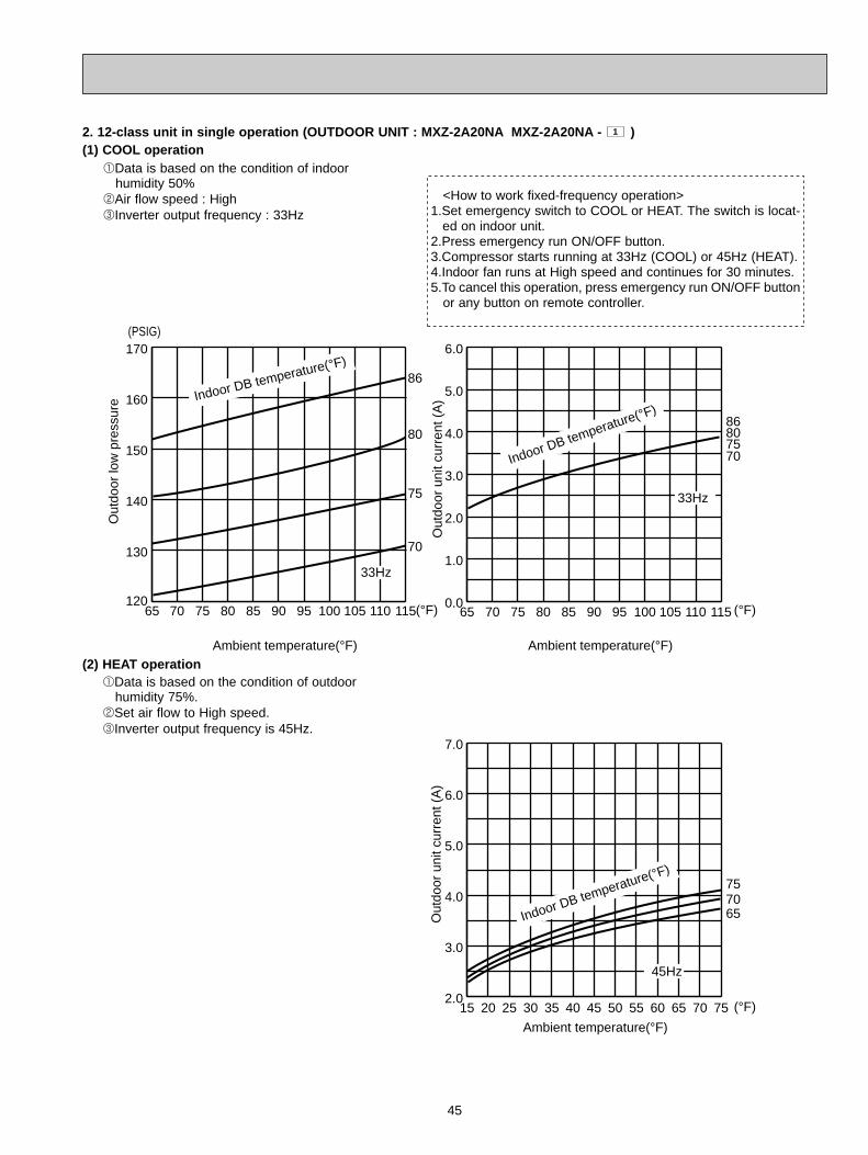
45
2. 12-class unit in single operation (OUTDOOR UNIT : MXZ-2A20NA MXZ-2A20NA - )(1) COOL operation
1
65 70 75 80 85 90 95 100 105 110 115120
140
150
160
170
130
Ambient temperature(°F)
(°F)
86
80
75
70
86807570
15 20 25 30 35 40 45 50 55 60 65 70 752.0
3.0
4.0
5.0
6.0
7.0
Ambient temperature(°F)
65 70 75 80 85 90 95 100 105 110 1150.0
1.0
2.0
3.0
4.0
5.0
6.0
Ambient temperature(°F)
(°F)
(°F)
(PSIG)
Out
door
low
pre
ssur
e
Out
door
uni
t cur
rent
(A
)O
utdo
or u
nit c
urre
nt (
A)
45Hz
33Hz
33Hz
657075
Indoor DB temperature(°F)
Indoor DB temperature(°F)
Indoor DB temperature(°F)
2Air flow speed : High3Inverter output frequency : 33Hz
(2) HEAT operation
1Data is based on the condition of indoor humidity 50%
<How to work fixed-frequency operation> 1.Set emergency switch to COOL or HEAT. The switch is locat-
ed on indoor unit.2.Press emergency run ON/OFF button.3.Compressor starts running at 33Hz (COOL) or 45Hz (HEAT).4.Indoor fan runs at High speed and continues for 30 minutes.5.To cancel this operation, press emergency run ON/OFF button
or any button on remote controller.
2Set air flow to High speed. 3Inverter output frequency is 45Hz.
1Data is based on the condition of outdoor humidity 75%.
OB444C--2.qxp 07.10.18 2:32 PM Page 45

46
3. 15-class unit in single operation (OUTDOOR UNIT : MXZ-2A20NA MXZ-2A20NA - )(1) COOL operation
1
65 70 75 80 85 90 95 100 105 110 115120
130
140
150
160
170
Ambient temperature(°F)
(°F)
86
80
75
70
86807570
15 20 25 30 35 40 45 50 55 60 65 70 752.0
3.0
4.0
5.0
6.0
7.0
Ambient temperature(°F)
65 70 75 80 85 90 95 100 105 110 1150.0
1.0
2.0
3.0
4.0
5.0
6.0
Ambient temperature(°F)
(°F)
(°F)
(PSIG)
Out
door
low
pre
ssur
e
Out
door
uni
t cur
rent
(A
)O
utdo
or u
nit c
urre
nt (
A)
45Hz
33Hz
33Hz
657075
Indoor DB temperature(°F)
Indoor DB temperature(°F)
Indoor DB temperature(°F)
(2) HEAT operation
<How to work fixed-frequency operation> 1.Set emergency switch to COOL or HEAT. The switch is locat-
ed on indoor unit.2.Press emergency run ON/OFF button.3.Compressor starts running at 33Hz (COOL) or 45Hz (HEAT).4.Indoor fan runs at High speed and continues for 30 minutes.5.To cancel this operation, press emergency run ON/OFF button
or any button on remote controller.
1Data is based on the condition of indoor humidity 50%
2Air flow speed : High 3Inverter output frequency : 33Hz
1Data is based on the condition of outdoor humidity 75%
2Set air flow to High speed. 3Inverter output frequency is 45Hz.
OB444C--2.qxp 07.10.18 2:32 PM Page 46

47
4. 09-class unit in single operation (OUTDOOR UNIT : MXZ-3A30NA MXZ-3A30NA - MXZ-4A36NA )(1) COOL operation
1
1Data is based on the condition of indoor humidity 50%
2Air flow speed : High3Inverter output frequency : 33Hz
(2) HEAT operation
65 70 75 80 85 90 95 100 105 110 115110
120
130
140
150
160
Ambient temperature(°F)
(°F)
86
80
75
70
Indoor DB temperature(°F)
65 70 75 80 85 90 95 100 105 110 1150.0
1.0
2.0
3.0
4.0
5.0
6.0
Ambient temperature(°F)
(°F)
(°F)15 20 25 30 35 40 45 50 55 60 65 70 752.0
3.0
4.0
5.0
6.0
7.0
Ambient temperature(°F)
Out
door
low
pre
ssur
e
Out
door
uni
t cur
rent
(A
)O
utdo
or u
nit c
urre
nt (
A)
45Hz
(PSIG)
33Hz
33Hz
65
7570
86807570Indoor DB temperature(°F)
Indoor DB temperature(°F)
<How to work fixed-frequency operation> 1.Set emergency switch to COOL or HEAT. The switch is locat-
ed on indoor unit.2.Press emergency run ON/OFF button.3.Compressor starts running at 33Hz (COOL) or 45Hz (HEAT).4.Indoor fan runs at High speed and continues for 30 minutes.5.To cancel this operation, press emergency run ON/OFF button
or any button on remote controller.
1Data is based on the condition of outdoor humidity 75%.
2Set air flow to High speed. 3Inverter output frequency is 45Hz.
OB444C--2.qxp 07.10.18 2:32 PM Page 47

48
5. 12-class unit in single operation (OUTDOOR UNIT : MXZ-3A30NA MXZ-3A30NA - MXZ-4A36NA )(1) COOL operation
1
65 70 75 80 85 90 95 100 105 110 115110
120
130
140
150
160
Ambient temperature(°F)
(°F)
86
80
75
70
86807570
15 20 25 30 35 40 45 50 55 60 65 70 752.0
3.0
4.0
5.0
6.0
7.0
Ambient temperature(°F)
65 70 75 80 85 90 95 100 105 110 1150.0
1.0
2.0
3.0
4.0
5.0
6.0
Ambient temperature(°F)
(°F)
(°F)
(PSIG)
Out
door
low
pre
ssur
e
Out
door
uni
t cur
rent
(A
)O
utdo
or u
nit c
urre
nt (
A)
45Hz
33Hz
33Hz
657075
Indoor DB temperature(°F)
Indoor DB temperature(°F)
Indoor DB temperature(°F)
2Air flow speed : High3Inverter output frequency : 33Hz
(2) HEAT operation
1Data is based on the condition of indoor humidity 50%
<How to work fixed-frequency operation> 1.Set emergency switch to COOL or HEAT. The switch is locat-
ed on indoor unit.2.Press emergency run ON/OFF button.3.Compressor starts running at 33Hz (COOL) or 45Hz (HEAT).4.Indoor fan runs at High speed and continues for 30 minutes.5.To cancel this operation, press emergency run ON/OFF button
or any button on remote controller.
1Data is based on the condition of outdoor humidity 75%.
2Set air flow to High speed. 3Inverter output frequency is 45Hz.
OB444C--2.qxp 07.10.18 2:32 PM Page 48

49
6. 15-class unit in single operation (OUTDOOR UNIT : MXZ-3A30NA MXZ-3A30NA - MXZ-4A36NA )(1) COOL operation
1
65 70 75 80 85 90 95 100 105 110 115120
130
140
150
160
170
Ambient temperature(°F)
(°F)
86
80
75
70
86807570
15 20 25 30 35 40 45 50 55 60 65 70 752.0
3.0
4.0
5.0
6.0
7.0
Ambient temperature(°F)
65 70 75 80 85 90 95 100 105 110 1150.0
1.0
2.0
3.0
4.0
5.0
6.0
Ambient temperature(°F)
(°F)
(°F)
(PSIG)
Out
door
low
pre
ssur
e
Out
door
uni
t cur
rent
(A
)O
utdo
or u
nit c
urre
nt (
A)
45Hz
33Hz
33Hz
657075
Indoor DB temperature(°F)
Indoor DB temperature(°F)
Indoor DB temperature(°F)
(2) HEAT operation
<How to work fixed-frequency operation> 1.Set emergency switch to COOL or HEAT. The switch is locat-
ed on indoor unit.2.Press emergency run ON/OFF button.3.Compressor starts running at 33Hz (COOL) or 45Hz (HEAT).4.Indoor fan runs at High speed and continues for 30 minutes.5.To cancel this operation, press emergency run ON/OFF button
or any button on remote controller.
1Data is based on the condition of outdoor humidity 75%
2Set air flow to High speed. 3Inverter output frequency is 45Hz.
2Air flow speed : High3Inverter output frequency : 33Hz
1Data is based on the condition of indoor humidity 50%
OB444C--2.qxp 07.10.18 2:32 PM Page 49

50
7. 17-class unit in single operation (OUTDOOR UNIT : MXZ-3A30NA MXZ-3A30NA - MXZ-4A36NA )(1) COOL operation
1
(2) HEAT operation
<How to work fixed-frequency operation> 1.Set emergency switch to COOL or HEAT. The switch is locat-
ed on indoor unit.2.Press emergency run ON/OFF button.3.Compressor starts running at 33Hz (COOL) or 45Hz (HEAT).4.Indoor fan runs at High speed and continues for 30 minutes.5.To cancel this operation, press emergency run ON/OFF button
or any button on remote controller.
65 70 75 80 85 90 95 100 105 110 115120
130
140
150
160
170
Ambient temperature(°F)
(°F)
86
80
75
70
86807570
15 20 25 30 35 40 45 50 55 60 65 70 752.0
3.0
4.0
5.0
6.0
7.0
Ambient temperature(°F)
65 70 75 80 85 90 95 100 105 110 1150.0
1.0
2.0
3.0
4.0
5.0
6.0
Ambient temperature(°F)
(°F)
(°F)
(PSIG)
Out
door
low
pre
ssur
e
Out
door
uni
t cur
rent
(A
)O
utdo
or u
nit c
urre
nt (
A)
45Hz
33Hz
33Hz
657075
Indoor DB temperature(°F)
Indoor DB temperature(°F)
Indoor DB temperature(°F)
1Data is based on the condition of outdoor humidity 75%.
2Set air flow to High speed. 3Inverter output frequency is 45Hz.
2Air flow speed : High3Inverter output frequency : 33Hz
1Data is based on the condition of indoor humidity 50%
OB444C--2.qxp 07.10.18 2:32 PM Page 50

51
8. 24-class unit in single operation (OUTDOOR UNIT : MXZ-3A30NA MXZ-3A30NA - MXZ-4A36NA )(1) COOL operation
1
65 70 75 80 85 90 95 100 105 110 115130
140
150
160
170
180
Ambient temperature(°F)
(°F)
15 20 25 30 35 40 45 50 55 60 65 70 752.0
3.0
4.0
5.0
6.0
7.0
Ambient temperature(°F)
65 70 75 80 85 90 95 100 105 110 1151.0
2.0
3.0
4.0
5.0
6.0
7.0
Ambient temperature(°F)
(°F)
(°F)
(PSIG)
Out
door
low
pre
ssur
e
Out
door
uni
t cur
rent
(A
)O
utdo
or u
nit c
urre
nt (
A)
45Hz
33Hz
33Hz
86807570
757065
Indoor DB temperature(°F)
Indoor DB temperature(°F)
Indoor DB temperature(°F)
86
80
75
70
(2) HEAT operation
<How to work fixed-frequency operation> 1.Set emergency switch to COOL or HEAT. The switch is locat-
ed on indoor unit.2.Press emergency run ON/OFF button.3.Compressor starts running at 33Hz (COOL) or 45Hz (HEAT).4.Indoor fan runs at High speed and continues for 30 minutes.5.To cancel this operation, press emergency run ON/OFF button
or any button on remote controller.
1Data is based on the condition of outdoor humidity 75%
2Set air flow to High speed. 3Inverter output frequency is 45Hz.
2Air flow speed : High3Inverter output frequency : 33Hz
1Data is based on the condition of indoor humidity 50%
OB444C--2.qxp 07.10.18 2:32 PM Page 51

SERVICE FUNCTIONS10
ACTUATOR CONTROL
52
9
Relation between main sensor and actuator
MXZ-2A20NA MXZ-2A20NA - MXZ-3A30NA MXZ-3A30NA - MXZ-4A36NA11
Discharge temperature thermistor
Indoor coil thermistor
Defrost thermistor
Gas pipe temperature thermistor(MXZ-2A20NA, MXZ-3A30NA)
Fin temperature thermistor
Ambient temperature thermistor
Outdoor heat exchanger temperature
Capacity code
Purpose
Protection
Defrosting Protection
Defrosting
Control
Protection
Control
Protection
Control
Compressor LEV Outdoor fan motor
4-wayvalve
SensorActuator
10-1. Pre-heat control <MXZ-2A20NA - , MXZ-3A30NA - , MXZ-4A36NA >If moisture gets into the refrigerant cycle, or when refrigerant is liquefied and collected in the compressor, it may interfere the start-up of the compressor.To improve start-up condition, the compressor is energized even while it is not operating. This is to generate heat at the winding.The compressor uses about 50 W when pre-heat control is turned ON.Pre-heat control is ON at initial setting.
[How to deactivate pre-heat control]
1 Turn OFF the power supply for the air conditioner before making the setting.2 Set the 4th Dip Switch of SW1 on the outdoor electronic control P.C. board to ON to deactivate pre-heat control func-
tion (MXZ-2A20NA - ).Set the 4th Dip Switch of SW2 on the outdoor electronic control P.C. board to ON to deactivate pre-heat control func-tion (MXZ-3A30NA - , MXZ-4A36NA).
3 Turn ON the power supply for the air conditioner.
NOTE: Pre-heat control will be turned OFF when the breaker is turned OFF.
1
1
11
ONSW2
1 2 3 4 5 6
ONSW2
1 2 3 4 5 6
MXZ-3A30NA -MXZ-4A36NA
SW2SW1
SW871
ONSW1
1 2 3 4
MXZ-2A20NA -ON
1 2 3 4
SW1 1
1
OB444C--2.qxp 07.10.18 2:32 PM Page 52

53
10-2. Auto line correcting <MXZ-3A30NA - , MXZ-4A36NA >Outdoor unit has an auto line correcting function which automaticallydetects and corrects improper wiring or piping.
1
Improper wiring or piping can be automatically detected by pressing the piping/wiring correction switch (SW871). When improper wiring or piping is detected, wiring lines are corrected. This will be completed in about 10 to 15 minutes.
[How to activate this function]
1. Check that outside temperature is above 0:. (This function does not work when outside temperature is not above 0:.) 2. Check that the stop valves of the liquid pipe and gas pipe are open. 3. Check that the wiring between indoor and outdoor unit is correct. (If the wiring is not correct, this function does not work.) 4. Turn ON the power supply and wait at least 1 minute. 5. Press the piping/wiring correction switch (SW871) on the electronic control P.C. board. Do not touch energized parts.
6. Press the switch to cancel.
NOTE : Indoor unit cannot be operated while this function is activated. When this function is activated while indoor unit is operating, the operation will be stopped. Operate indoor unit after the auto line correcting is finished. Pressing the switch during detection cancels this function.
SW871
W Be sure to check for closed valves, cracked pipes or clogged pipes.
LED indication after cancel :
LED1(Red)Lighting
LED indication during detection:
LED indication after detection:
LED2(Yellow)Lighting
LED3(Green)Blinking
LED1(Red)Lighting
LED2(Yellow)Lighting
LED3(Green)Goes out
LED1(Red)LightingBlinking
LED2(Yellow)Goes outBlinking
Other indications
LED3(Green)LightingBlinking
Completed (Detected successfully)Cannot be correctedRefer to "SAFETY PRECAUTIONS WHEN LED FLASHES"located behind the service panel.
Indication
SW871
Press the switch for more than 5 seconds.LED will show the record of auto correcting for about 30 seconds as shown in the table below:
NOTE : Activate this function to confirm the correct wiring after replacing the electronic control P.C. board. (Previous records are deleted when the electronic control P.C. board is replaced.) The record cannot be shown if auto line correcting is not canceled (Refer to "How to activate this function").
LED1(Red)Once
3 times
LED2(Yellow)Once
3 times
LED3(Green)LightingLighting
Not correctedCorrected
Number of blinksWiring line
The record of auto line correcting can be confirmed in the following way:
OB444C--2.qxp 07.10.18 2:32 PM Page 53

TROUBLESHOOTING
54
11
3. Troubleshooting procedure1) First, check if the OPERATION INDICATOR lamp on the indoor unit is flashing on and off to indicate an abnormality.
To make sure, check how many times the abnormality indication is flashing on and off before starting service work.2) If the electronic control P.C. board seems to be defective, check the copper foil pattern for disconnection and the com-
ponents for bursting and discoloration.3) When troubleshooting, refer to 11-2, and 11-3. and 11-4.
Lead wiring Housing point
11-1. Cautions on troubleshooting1. Before troubleshooting, check the following:
1) Check the power supply voltage.2) Check the indoor/outdoor connecting wire for mis-wiring.
2. Take care of the following during servicing.1) Before servicing the air conditioner, be sure to turn off the unit first with the remote controller, and then after confirm-
ing the horizontal vane is closed, turn off the breaker and/or disconnect the power plug.2) Be sure to turn OFF the power supply before removing the front panel, the cabinet, the top panel, and the electronic
control P.C. board.3) When removing the electrical parts, be careful to the residual voltage of smoothing capacitor.4) When removing the electronic control P.C. board, hold the edge of the board with care NOT to apply stress on the
components.5) When connecting or disconnecting the connectors, hold the housing of the connector. DO NOT pull the lead wires.
MXZ-2A20NA MXZ-2A20NA - MXZ-3A30NA MXZ-3A30NA - MXZ-4A36NA11
11-2. Failure mode recall functionThis air conditioner can memorize the abnormal condition which has occurred once.Even though LED indication listed on the troubleshooting check table (11-4.) disappears, the memorized failure detailscan be recalled.This mode is very useful when the unit needs to be repaired for the abnormality which doesn’t recur.
1. Type of failure mode recall functionThere are 2 types in failure mode recall function as shown below.1Indoor and outdoor unit failure mode recall function
With this function, failure mode of indoor unit and a part of failure mode of outdoor unit can be recalled. 2The details of outdoor unit failure mode recall function
With this function, more detailed failure mode of outdoor unit can be recalled.
Refer to the service manual of indoor unit for how to recall the failure mode and the details of indoor unit failure mode.The outdoor unit failure mode is indicated by the operation indicator lamp on the indoor unit and the LED of outdoor unit.See "11-2.2. Failure mode table".
OB444C--2.qxp 07.10.18 2:32 PM Page 54

55
The left lamp of OPERATION INDICATOR
lamp (Indoor unit)
OFF2-time flash
3-time flash
4-time flash
5-time flash
6-time flash
7-time flash
8-time flash
Lighting Lighting
Lighting Once
Lighting OnceLighting Twice
Lighting 3 timesLighting 4 times
Lighting 9 times
Once Goes out
Lighting Lighting
Lighting Lighting
3 times Goesout
4 times Goesout
Lighting Lighting
Lighting Lighting
Lighting 5 times9-time flash
10-time flash
• Check the connection of the compressor connecting wire.
• Refer to 11-6.E "How to check inverter / compressor".• Check the stop valve.
• Replace the outdoor electronic control P.C. board.
•Check refrigerant circuit and refrigerant amount.• Refer to 11-6.D "Check of LEV".
• Refer to 11-6.G "Check of outdoor fan motor".
• Replace the outdoor electronic control P.C. board.•Check refrigerant circuit and refrigerant amount.• Refer to 11-6.D "Check of LEV".
• Reconnect compressor connector.• Refer to 11-6.E "How to check inverter/ compressor".• Check the stop valve.
•Check refrigerant circuit and refrigerant amount.• Check the stop valve.
• Check around outdoor unit.• Check outdoor unit air passage.• Refer to 11-6.G "Check of outdoor fan motor".
• Refer to 11-6.F "Check of outdoor thermistors".
• Refer to 11-6.F "Check of outdoor thermistors".
When overcurrent protection stop is continuously performed three times within 1 minute after the compressor gets started, or when converterprotection stop or bus-bar voltageprotection stop is continuouslyperformed three times within 3minutes after start-up.
When thermistor shorts or opens during compressor running.
When 28A current flows into intelligentpower module.
When discharge temperature exceeds 240.8˚F during operation. Compressor can restart if dischargetemperature thermistor reads 212˚F or less 3 minutes later.
When high-pressure is detectedwith the high-pressure switch(HPS) during operation.(MXZ-3A30NA,MXZ-3A30NA- 1 , MXZ-4A36NA)When the outdoor heat exchangertemperature exceeds 158˚Fduring cooling or the indoor gaspipe temperature exceeds 158˚Fduring heating.
When the fin temperature exceeds188.6˚F during operation.
When the P.C. board temperatureexceeds 158˚F during operation.
When failure occurs continuouslythree times within 30 seconds afterthe fan gets started.
When nonvolatile memory datacannot be read properly.
When the frequency of thecompressor is kept 80Hz ormore and the dischargetemperature is kept under 102.2˚Ffor more than 20 minutes.
Outdoor power system
Discharge temperaturethermistor
Defrost thermistorAmbient temperature thermistor
Fin temperature thermistorP.C. board temperaturethermistor
Outdoor heat exchanger temperature thermistor
Overcurrent
Discharge temperature
High pressure
Fin temperature
P.C. board temperature
Outdoor fan motor
Nonvolatile memory data
Discharge temperature
- -
Gas pipe temperaturethermistor A
Lighting 10 times
Gas pipe temperaturethermistor B
Lighting 11 times
Gas pipe temperaturethermistor C
Lighting 12 times
When a short or open circuit isdetected in the thermistor duringcooling.(A,B: MXZ-2A20NA, MXZ-3A30NA)(C : MXZ-3A30NA)
None (Normal)
Abnormal point(Failure mode / protection)
Condition CorrespondenceIndoor/outdoor
unit failure moderecall function
LED indication(Outdoor P.C. board)LED 1 LED 2
2. Outdoor unit failure mode table
NOTE : Blinking patterns of this mode differ from the ones of Troubleshooting check table (11-4.).
OB444C--2.qxp 07.10.18 2:32 PM Page 55

56
Operation start
Check the outdoor unit LED indicator.
Refer to 11-6.A "Check of power supply".
• Indoor unit serial signal errorRefer to 11-6.B "How to check mis-wiring andserial signalerror".
• COOL or HEAToperation onlyRefer to 11-6.C "Check of R.V. coil".
• When cooling, room is not cool.Refer to 11-6.E "How to checkinverter/compressor".
• When cooling, heat exchanger of non-operating indoor unit frosts.•When heating, non- operating indoor unit gets warm.Refer to 11-6.D "Check of LEV".
• When cooling,dew drops in the non-operating indoor unit.Check of mis-piping
• When heating,room does not get warm.Refer to 11-6.E "How to checkinverter/ compressor".Check mis-piping, shortage of capacity.
Refer to 11-4. "Troubleshooting check table".
OFF
Both LED 1 and LED 2 lighting
LED 1 or LED 2has blinked.
11-3. Instruction of troubleshooting• Check the indoor unit with referring to the indoor unit service manual, and confirm that there is any problem in the indoor
unit.Then, check the outdoor unit with referring to this page.
11-time flash
15-time flash
• Check the connecting wire between outdoor electronic control P.C. board and power board.
• Replace the power board.
• Check the connecting wire among electronic control P.C. board, noise filter P.C. board and power board.
• Replace the power board.
• Refer to 11-6.D "Check of LEV". • Check the drain pump of the indoor unit.
When the communication betweenboards protection stop iscontinuously performed twice.
Communication error occursbetween the electronic control P.C.board and power board for morethan 10 seconds.
Current sensor protection stop iscontinuously performed twice.
When a short or open circuit isdetected in the current sensorduring compressor operating.
The protection stop of the zerocross detecting circuit iscontinuously performed 10 times.
When zero cross signal cannot bedetected while the compressor isoperating.
When a failure is detected in theoperation of the converter duringoperation.
When the bus-bar voltage exceeds400V or falls to 200V or belowduring compressor operating.
When the bus-bar voltage exceeds400V or falls to 50V or below duringcompressor operating.
Communication errorbetween P.C. boards
Current sensor
Zero cross detecting circuit
Converter
Bus-bar voltage(1)
Bus-bar voltage(2)wEven if this protection stop isperformed continuously threetimes, it does not mean theabnormality in outdoor powersystem.
LEV for drain
Lighting 6 times
Lighting 7 times
5 times Goesout
5 times Goesout
5 times
6 times
Goesout
Goesout
When the indoor unit detects anyabnormal in the LEV for drain.
Lighting Lighting
Abnormal point(Failure mode / protection)
Condition CorrespondenceIndoor/outdoor
unit failure moderecall function
LED indication(Outdoor P.C. board)LED 1 LED 2
The left lamp of OPERATION INDICATOR
lamp(Indoor unit)
NOTE : Blinking patterns of this mode differ from the ones of Troubleshooting check table (11-4.).
OB444C--2.qxp 07.10.18 2:32 PM Page 56

57
11-4. Troubleshooting check table
LED2 LED1
Outdoor electronic control P.C. board (Parts side)
Lighting
LED1 LED2
Lighting
LED1(Red) LED2(Yellow)
Lighting Twice Outdoor power system
• Check the connection of the compressor connecting wire.
• Refer to 11-6.E "How to check inverter/compressor". • Check the stop valve.
Lighting 3 timesDischarge temperaturethermistor
• Refer to 11-6.F "Check of outdoor thermistors".
• Refer to 11-6.F "Check of outdoor thermistors".
Outdoor heat exchangertemperature thermistor
Defrost thermistor
Lighting 7 times Nonvolatile memory data • Replace the outdoor electronic control P.C. board.
Lighting 8 times Current sensor • Replace the power board.
Lighting 11 timesCommunication errorbetween P.C. boards
• Check the connecting wire between outdoor electronic control P.C. board and power board.
Lighting 12 timesZero cross detectingcircuit
• Check the connecting wire among outdoor electronic control P.C. board, noise filter P.C. board and power board.
Abnormal point / Condition Correspondence
When a short circuit is detected in the thermistor during operation, orwhen an open circuit is detected in the thermistor after 5 minutes (incooling) and 10 minutes (in heating) of compressor start-up.
When a short circuit is detected in the thermistor during operation, orwhen an open circuit is detected in the thermistor after 5 minutes ofcompressor start-up.
• Refer to 11-6.F "Check of outdoor thermistors".
• Replace the outdoor electronic control P.C. board.
Indication
When over current protection stop is continuously performed three times within 1 minute after the compressor gets started, or when converter protection stop or bus-bar voltage protection stop is continuously performed three times within 3 minutes after start-up.
When a short circuit is detected in the thermistor during operation, orwhen an open circuit is detected in the thermistor after 10 minutes of compressor start-up.
Condition
When the nonvolatile memory data cannot be read properly.
Fin temperaturethermistor
P.C board temperaturethermistor
Lighting 4 times
Ambient temperaturethermistor
Current sensor protection stop is continuously performed twice.
When the communication protection stop between boards is continuously performed twice.
The protection stop of the zero cross detecting circuit is continuouslyperformed 10 times.
When a short or open circuit is detected in the thermistor duringoperation.
When a short or open circuit is detected in the thermistor duringoperation.
5 timesLighting
IPM protection
Lock protection
3 times Goes outDischarge temperatureprotection
• Check the amount of gas and refrigerant circuit.
• Refer to 11-6.D "Check of LEV".
Fin temperatureprotection P.C. board temperatureprotection
High-pressureprotection
8 times Goes outConverter protection
• Replace the power board.
Bus-bar voltageprotection (1)
• Replace the power board.Bus-bar voltageprotection (2)
13 times Goes out Outdoor fan motor • Refer to 11-6.G "Check of outdoor fan motor".
Lighting 8 timesCurrent sensorprotection • Replace the power board.
Lighting 11 timesCommunication between P.C.boards protection
• Check the connecting wire between outdoor electronic control P.C. board and power board.
Lighting 12 timesZero cross detecting circuitprotection
• Check the connecting wire among outdoor electronic control P.C. board, noise filter P.C. board and power board.
•Check refrigerant circuit and refrigerant amount.
•Refer to 11-6.G "Check of outdoor fan motor".
• Check around of gas and the refrigerant circuit.• Check of stop valve.
• Reconnect compressor connector.
• Refer to 11-6.E "How to check inverter/compressor". • Check the stop valve.• Check the power module (PAM module).
Twice Goes out
4 times Goes out
5 times Goes out
9 times Goes out
When overcurrent is detected after 30 minutes of compressor start-up.
When overcurrent is detected within 30 minutes of compressor start-up
When the bus-bar voltage exceeds 400V or falls to 200V or below during compressor operating.
When the bus-bar voltage exceeds 400V or falls to 50V or below during compressor operating.
When discharge temperature exceeds 240.8˚F during operation. Compressor can restart if discharge temperature thermistor reads 212˚F or less 3 minutes later.
When the fin temperature exceeds 188.6˚F during operation.
When the P.C. board temperature exceeds 158˚F during operation.
When high-pressure is detected with the high-pressure switch (HPS)during operation. (MXZ-3A30NA , MXZ-3A30NA - 1 , MXZ-4A36NA)
When failure occurs continuously three times within 30 seconds after the fan gets started.
When a short or open circuit is detected in the current sensor duringcompressor operating.
Communication error occurs between the outdoor electronic control P.C. board and power board for more than 10 seconds.
When zero cross signal cannot be detected while the compressor isoperating.
When the outdoor heat exchanger temperature exceeds 158˚F during cooling or when indoor gas pipe temperature exceeds 158˚Fduring heating.
When a failure is detected in the operation of the converter duringoperation.
Outdoor unit does not operate.
Lighting Once LEV for drain• Refer to 11-6.D "Check of LEV".• Check the drain pump of the indoor unit.When the indoor unit detects any abnormality in the LEV for drain.
• Refer to 11-6.F "Check of outdoor thermistors".Lighting 10 times
Gas pipe temperature thermistor A
Gas pipe temperaturethermistor B
Gas pipe temperaturethermistor C
When a short or open circuit is detected in the thermistor during cooling.(A,B : MXZ-2A20NA, MXZ-3A30NA)(C : MXZ-3A30NA)
No.
1
2
3
4
5
6
7
8
10
9
11
12
13
14
15
16
17
18
19
20
Symptom
'Outdoor unit stops and restarts 3 minutes later' is repeated.
MXZ-2A20NA, MXZ-2A20NA- 1 , MXZ-3A30NA
MXZ-3A30NA- 1 , MXZ-4A36NA
ON
OFF2.5-second OFF 2.5-second OFF
The flashing frequency shows the number of times the LED blinks after every 2.5-second OFF.(Example) When the flashing frequency is “2”.
0.5-second ON 0.5-second ON
NOTE 1. The location of LED is illustrated at the right figure. Refer to 11-7.1.2. LED is lighted during normal operation.
OB444C--2.qxp 07.10.18 2:32 PM Page 57

58
Primary current protection
Secondary current protection
High-pressure protection
Defrosting in cooling
3 times Lighting Discharge temperatureprotection
• Check refrigerant circuit and refrigerant amount.• Refer to 11-6.D "Check of LEV".• Refer to 11-6.F "Check of outdoor thermistors".
4 times LightingLow dischargetemperature protection
• Refer to 11-6.D "Check of LEV".• Check refrigerant circuit and refrigerant amount.
5 times LightingCooling high-pressureprotection
This symptom does not mean any abnormality of theproduct, but check the following points.• Check if indoor filters are clogged. • Check if refrigerant is short.• Check if indoor/outdoor unit air circulation is short cycled.
-
-
These symptoms do not mean any abnormality of theproduct, but check the following points.• Check if indoor filters are clogged.• Check if refrigerant is short.• Check if indoor/outdoor unit air circulation is short cycled.Twice Lighting
Once Lighting
When the frequency of the compressor is kept 80Hz or more and the discharge temperature is kept under 122˚F(COOL mode)/104˚F(HEAT mode) for more than 40 minutes.
When the frequency of the compressor is kept 80Hz or more and the discharge temperature is kept under 102.2˚F for more than 20minutes.
When the outdoor heat exchanger temperature exceeds 136.4˚Fduring operation.
9 times Lighting Inverter check mode
Lighting Lighting Normal
When the unit is operated with emergency operation switch.
-
When the input current exceeds 15A.
When the current of the compressor exceeds 15A.
When the indoor gas pipe temperature exceeds 113˚F during heating.
When the indoor gas pipe temperature falls 37.4˚F or below during cooling.
Outdoor electronic control P.C. board(Parts side)
LED2 LED1
Lighting
LED1 LED2
Lighting
MXZ-2A20NA, MXZ-2A20NA- 1 , MXZ-3A30NA
MXZ-3A30NA- 1 , MXZ-4A36NA
LED1(Red) LED2(Yellow)Abnormal point / Condition Correspondence
IndicationCondition
Outdoor unit operates.
Outdoor unitoperatesnormally.
No. Symptom
21
22
23
24
25
26
27
ON
OFF2.5-second OFF 2.5-second OFF
The flashing frequency shows the number of times the LED blinks after every 2.5-second OFF.(Example) When the flashing frequency is “2”.
0.5-second ON 0.5-second ON
NOTE 1. The location of LED is illustrated at the right figure. Refer to 11-7.1.2. LED is lighted during normal operation.
OB444C--2.qxp 07.10.18 2:32 PM Page 58

59
11-5. Trouble criterion of main parts MXZ-2A20NA MXZ-2A20NA - MXZ-3A30NA MXZ-3A30NA - MXZ-4A36NA11
Normal
Discharge temperaturethermistor (RT62)
Fin temperature thermistor (RT64)
WHT - REDRED - ORN
Measure the resistance using a tester. (Part temperature : 14˚F ~ 104˚F)
37.4" ~ 53.9"
Part name Check method and criterion
1.2k" ~ 1.56k"
Measure the resistance between terminals using a tester.(Winding temperature : 14˚F ~ 104˚F)
Compressor
W
UVWHT
RED
BLK
LEV
WHT
URED
WHT
BLK
V
W
(W)
(V)
(U)
RED
YLW BRN
ORN
BLU
Measure the resistance between lead wires using a tester.(Part temperature : 14˚F ~ 104˚F)
Outdoor fan motor
R.V. coil
Measure the resistance using a tester.(Part temperature : 14˚F ~ 104˚F)Linear expansion valve
Color of lead wire Normal
YLW - BRNBRN - BLU
Normal (Each phase)
13.4" ~ 16.4"
Pressure Normal
HPS537 ± 22 PSIG696 PSIG Open
Close
High pressure switch(HPS) MXZ-3A30NA
MXZ-4A36NAMXZ-3A30NA - 1
Defrost thermistor(RT61)
Ambient temperature thermistor (RT65)
Outdoor heat exchangertemperature thermistor(RT68)
Gas pipe temperaturethermistor (RT6A~C)MXZ-2A20NAMXZ-3A30NA
Measure the resistance with a tester.
Refer to 11-7. “Test point diagram and voltage”,1. “Outdoor electronic control P.C.board”, the chart of thermistor.
Measure the resistance with a tester.Before measurement, hold the thermistor with your hands to warm it up.
Refer to 11-7. “Test point diagram and voltage”,1. “Outdoor electronic control P.C.board”, the chart of thermistor.
+ 7- 15
MXZ-2A20NA - 1MXZ-2A20NA
0.39"~ 0.49" 0.86"~ 1.06" 1.29"~ 1.49"
Normal (Each phase)MXZ-3A30NA
MXZ-4A36NAMXZ-3A30NA - 1
OB444C--2.qxp 07.10.18 2:32 PM Page 59

60
AA Check of power supply
Outdoor unit does not operate. (LED display: display OFF)
Turn ON the power supply.
No
Yes
Yes
No
Yes
No
Yes
NoReplace the power board.
Check the connecting of parts of main power supply circuit.
Is there voltage of 208/230V AC in the power supply terminal block?
Is the output voltage from the noisefilter P.C. board 208/230V AC?
Is the input voltage to the outdoor electronic control P.C. board 294/325V DC?
Check the power supply cable.
Replace the outdoor electronic control P.C. board.
Replace the noise filter P.C. board.
Is the input voltage to the power board208/230V AC? Replace the reactor.
11-6. Troubleshooting flow
MXZ-2A20NA MXZ-2A20NA - MXZ-3A30NA MXZ-3A30NA - MXZ-4A36NA11
OB444C--2.qxp 07.10.18 2:32 PM Page 60

61
Is there rated voltage in the power supply?
Is there any mis-wiring, poor contact, or wire disconnection of the indoor/outdoor connecting wire?
W1 Mis-wiring may damage indoor electronic control P.C. board during the operation. Be sure to confirm the wiring is correct before the operation starts.
(Lighted or not lighted)
No
Yes
No
Yes
Yes
No
Yes
No
Yes
W2 Be careful to the residual voltage of smoothing capacitor.
Be sure to release the failure-moderecall function after checking.
No
No
Yes
No
Yes
Yes
Yes
No
Yes
Refer to indoor unit service manual.
Turn OFF the power supply.
Turn ON the power supply.
Is there rated voltage betweenoutdoor terminal block S1 andS2?
Does the left lamp of OPERATIONINDICATOR lamp light up? <Confirmation of the power to the indoor unit>
Press EMERGENCY OPERATION switch once.
Check the powersupply.
A
Turn OFF the power supply.Check once more if the indoor/outdoorconnecting wire is not mis-wiring.Short-circuit outdoor terminal block S2 andS3.W1
B
Turn ON the power supply.
Check the wiring.
Correct them.
Turn OFF the power supply.Remove the short-circuit betweenoutdoor terminal block S2 and S3.Turn ON the power supply.Is there amplitude of 10 to 20V DCbetween outdoor terminal block S2and S3? <Confirmation of serialsignal>
Is there rated voltage between indoor terminal block S1 and S2?<Confirmation of power voltage>
Replace the indoor electronic control P.C. board.
Replace the outdoor electronic control P.C. board.W2
Is there any error of theindoor/outdoor connecting wire,such as the damage of the wire,intermediate connection, poorcontact to the terminal block?
Is there any error of theindoor/outdoor connecting wire,such as the damage of the wire,intermediate connection, poorcontact to the terminal block?
No
Replace theindoor/outdoorconnecting wire.
Replace theindoor/outdoorconnecting wire.
Is serial signalerror indicated 6 minutes later?
Yes
No
· Turn OFF inverter-controlled lighting equipment.
· Turn OFF the power supply and then turn ON again.
· Press EMERGENCY OPERATION switch.
B
· Reinstall either the unit or the light each other away.
· Attach a filter on remote control receiving section of the indoor unit.
A
Is serial signal error indicated 6 minutes later?
No
Does the LED on the outdoor electronic control P.C. board repeat "3.6-second-OFF and 0.8-second-ON quick blinking"?
MXZ-3A30NA -MXZ-4A36NA
MXZ-2A20NAMXZ-2A20NA - MXZ-3A30NA
1
1
LED indication for communication statusCommunication status is indicated by the LED.
Blinking: normal communicationLighting: abnormal communication or not connected
Pattern 1 and 2 is repeatedly displayed alternately. Each pattern is displayed for 15 seconds.
NOTE: "Lighting" in the table below does not indicate abnormal communication.
Outdoor electronic control P.C. board
Blinking
LED 3
Lighting
Goes out
LED 1LED 2
(Parts side)
LED3 LED2 LED1
Outdoor electronic control P.C. board
Blinking
(Parts side)
LED1 LED2 LED3
Unit status
Pattern
1
2
Unit Bstatus
Lighting
Unit AstatusUnit Cstatus
LED 1 LED 3LED 2Pattern
1
2
Unit Bstatus
Unit AstatusUnit Dstatus
Unit Cstatus
Goes outLighting
BB How to check mis-wiring and serial signal error
• When unit cannot operate neither by the remote controller nor by EMERGENCY OPERATION switch.Indoor unit does not operate.
• When OPERATION INDICATOR lamp flashes ON and OFF in every 0.5-second.Outdoor unit does not operate.
OB444C--3.qxp 07.10.18 2:25 PM Page 61

62
CC Check of R.V. coil
No
Yes
No
Yes
No
Yes
No
Yes
No
Yes
1. Disconnect the lead wire leading to the compressor.2. 3 minutes after turning ON the power supply, start EMERGENCY
OPERATION in HEAT mode.
Is there voltage of 208/230V AC between pin1 and pin 2 at connector CN912?
Turn OFF the power supply of indoor and outdoor unit.
1. Turn OFF the power supply of indoor and outdoor unit, and disconnect the connector CN781.
2. 3 minutes after turning ON the power supply, start EMERGENCY OPERATION in HEAT mode.
Replace the 4-way valve. Replace the power P.C. board or the noise filter P.C. board.
Replace the R.V. coil.
Is there voltage of 12V DC between the connector CN781 pin 5 (+) and pin 3 (-) ?
Replace the outdoor electronic control P.C. board.
Disconnect the connector CN912. Is there normal resistance to R.V. coil?
1. Disconnect the lead wire leading to the compressor.2. 3 minutes after turning ON the power supply, start EMERGENCY
OPERATION in COOL mode.
Is there voltage of 208/230V AC between pin1 and pin 2 at connector CN912? W
1. Turn OFF the power supply of the indoor and the outdoor unit, and disconnect the connector CN781.2. 3 minutes after turning ON the power supply, start
EMERGENCY OPERATION in COOL mode.
Replace the 4-way valve.
Replace the noise filter P.C. board.Is there voltage of 12V DC between the connector CN781 pin 5 (+) and pin 3 (-) ?
Replace the outdoor electronic control P.C. board.
W If the connector CN912 is not connected or R.V. coil is open, voltage occurs between terminals even when the control is OFF.
• When heating operation does not work.
• When cooling operation does not work.
The cooling operation or heating operation does not operate. (LED display: Both LED1 and LED2 lighting)
CN912CN781
Noise filter P.C. boardOutdoor electronic controlP.C. board
OB444C--3.qxp 07.10.18 2:25 PM Page 62

63
DD Check of LEV
No
Yes
No
Yes
Turn ON the power supply to the outdoor unit after checking LEV coil is mounted to the LEV body securely.
Is "click - click" sound heard?Or, do you feel vibration of LEV coil with your hand?
Disconnect the connectors. CN791: LEV A, CN792: LEV B, CN793: LEV C,CN794 : LEV D, CN795: LEV E, CN796: LEV F Is there normal resistance to LEV coil?
Normal
Replace the outdoor electronic control P.C. board.
Replace LEV coil.
• When cooling, heat exchanger of non-operating indoor unit frosts.• When heating, non-operating indoor unit get warm.
OB444C--3.qxp 07.10.18 2:25 PM Page 63

64
EE How to check inverter/ compressor
• When heating, room does not get warm.• When cooling, room does not get cool.
No
No
Yes
Yes
Yes
No
Yes
No
Disconnect the terminal of the compressor. 3 minutes after turning ON the power supply, start EMERGENCY OPERATION.
Is output balanced?
Clarify the causes by counting time until the inverter stops.0 to 10 seconds: compressor layer short 10 to 60 seconds: compressor lock60 seconds to 5minutes: refrigerant circuit defective5 minutes or more: normal
Measure the voltage between each lead wire leading to the compressor.U (BLK) - V (WHT) V (WHT) - W (RED) W (RED) - U (BLK)Output voltageCOOL: 150V(48Hz) HEAT: 170V(64Hz)Is voltage output? W1, W2
Turn OFF the power supply of indoor and outdoor unit, and measure the compressor winding resistance between the compressor terminals.Is the resistance between each terminal normal?
Is the input voltage to the outdoor electronic control P.C. board 370V or more?
Reconnect the lead wire of compressor, and turn ON the power supply to indoor and outdoor unit. 3 minutes later, start EMERGENCY OPERATION.
Replace the compressor.
Replace the power board.
W1 • After the outdoor fan starts running, wait for 1 minute or more before measuring the voltage.
• The output voltage values have the tolerance of i20%.W2 • The output differs depending on the capacity or the
number of indoor units to be operated.
OB444C--3.qxp 07.10.18 2:25 PM Page 64

65
FF Check of outdoor thermistors
• When thermistor is abnormal.
ThermistorDefrostDischarge temperatureOutdoor heat exchanger temperature Gas pipe temperature (Unit A) wGas pipe temperature (Unit B) wGas pipe temperature (Unit C) wAmbient temperatureFin temperature
w Except MXZ-2A20NA - , MXZ-3A30NA - and MXZ-4A36NA.
SymbolRT61RT62RT68RT6ART6BRT6CRT65RT64
Connector, Pin No.Between CN661 pin1 and pin2Between CN661 pin3 and pin4Between CN661 pin7 and pin8 Between CN662 pin1 and pin2Between CN662 pin3 and pin4Between CN662 pin5 and pin6Between CN663 pin1 and pin2Between CN3 pin1 and pin2
Outdoor electronic control P.C. board
Outdoor power board
Board
1 1
GG Check of outdoor fan motor
• Fan motor does not operate or stops operating shortly after starting the operation.
Yes
Yes
YesNo
(Fixed to either 5V or 0V DC)
No
No
Check the connection between the connectors CN931 and CN932.
Disconnect CN932 from outdoor electronic control P.C. board, and turn ON the power supply.
Rotate the outdoor fan motor manually and measure the voltage of CN931.Between 1(+) and 5(-)Between 2(+) and 5(-)Between 3(+) and 5(-)
Is the resistance between each terminalof outdoor fan motor normal?
Does the outdoor fan motor rotate smoothly?
Does the voltage between each terminal become 5V DC and 0V DCrepeatedly?
Replace the outdoor DC fan motor. Replace the outdoor electronic control P.C. board.
Normal
Yes
No
Abnormal
Reconnect the connector in the following table and disconnect the lead wire leading to the compressor. 3 minutes after turning ON the power supply, start EMERGENCY OPERATION.
Disconnect the connector in the following table and measure the resistance of the thermistor to check whether the thermistor is normal or not.
Does the unit operate 10 minutes or more without showing thermistor abnormality?
Replace the thermistor except RT64. In case that RT64 is abnormal, replace the outdoor power board since RT64 is combined with the outdoor power board.
Normal
Replace the outdoor electronic controlP.C. board or the outdoor power board.
OB444C--3.qxp 07.10.18 2:25 PM Page 65

66
HH Check of HPS
Infinity
0 "
No
Yes
1. Disconnect the connector CN681 in the electronic control P.C. board.2. Check the resistance of HPS after 1 minute has passed since the outdoor unit power supply was turned OFF.
Check the resistance between each terminal.
Reconnect CN681.Turn ON the power supply to the indoor and outdoor unit.3 minutes later, start EMERGENCY OPERATION.
Is HPS protection displayed immediately after compressor starts?
Replace HPS.
Replace the electronic control P.C. board.
Normal
II The other cases
Indoor unit does not operate. (different operating models in multi system)• When you try to run two indoor units simultaneously, one for cooling and the other for heating, the unit which
transmits signal to the outdoor units earlier decides the operation mode. • When the above situation occurs, set all the indoor units to the same mode, turn OFF the indoor units, and
then turn them back ON.• Though the top of the indoor unit sometimes gets warm, this does not mean malfunction. The reason is that
the refrigerant gas continuously flows into the indoor unit even while it is not operating.
• When the operation frequency does not go up from lowest frequency.
MXZ-3A30NA MXZ-3A30NA - MXZ-4A36NA1
OB444C--3.qxp 07.10.18 2:25 PM Page 66

700
600
500
400
300
200
100
0
Res
ista
nce
(k"
)
Temperature (˚F)
Discharge temperature thermistor (RT62)
32 50 68 86 104 122 140 158 176 194 212 230 248
-4 -14 32 50 68 86 104
100
90
80
70
60
50
40
30
20
10
0
200
180
160
140
120
100
80
60
40
20
0
Res
ista
nce
(k"
)
Res
ista
nce
(k"
)
Temperature (˚F)
Temperature (˚F)
32 50 68 86 104 122 140 158 176
w Except MXZ-2A20NA - .1
Defrost thermistor (RT61)Ambient temperature thermistor (RT65)Gas pipe temperature thermistor (RT6A,6B,6C)wOutdoor heat exchanger temperaturethermistor (RT68)
Fin temperature thermistor (RT64)
67
LED 1
LED 2
CN801294V DC
~370V DC
Input
( (
(
LEV
Room
A
(
12V D
Cpulse w
ave
(
LEV
Room
B
(
12V D
Cpulse w
ave
(LE
V R
oomC
(
12V D
Cpulse w
ave
(High pressure sw
itch
(Gas pipe C therm
istor w
(Gas pipe B therm
istor w
(Gas pipe A
thermistor w
CN
93220-90V
AC GN
D5V
5V D
Cpulse w
ave
( To fanm
otor
Defrost therm
istor (RT
61)
Discharge tem
perature thermistor (R
T62)
Outdoor heat exchanger
temperature therm
istor (RT
68) ( ((+)
(–)(+)
Rush current relay(–)
R.V. coil (–)
( 12VD
C
15V15V(+
)(–)
CN
931 (
CN
661
CN
701S
ignal transmission
(To power board)
5V D
C pulse w
ave
(+)
(–)
(G
ND
CN
702S
ignal reception(F
rom pow
er board)5V
DC
pulse wave
GN
D (pow
er board)
CN
781
LEV
E ((+
)
(–) ((+)
(–) ((+)
(–) (
CN
791
CN
792
CN
793
CN
681
CN
662
( ( (
F801FUSE
T3.15AL250V
LED 3
(A
mbient tem
peraturetherm
istor (RT
65)C
N663
Serial signal Room C12~24V DC
Serial signal Room B
12~24V DC
Serial signal Room A
12~24V DC
CN603
CN602
CN601
208/230V ACInput
SW1
CN
79512V
DC
pulse wave
11-7. Test point diagram and voltage1. Outdoor electronic control P.C. boardMXZ-2A20NA MXZ-2A20NA - MXZ-3A30NA1
MX
Z-3A
30NA
OB444C--3.qxp 07.10.18 2:25 PM Page 67

68
MXZ-3A30NA - MXZ-4A36NA1
LED 1LED 2
F931FUSE
T3.15AL250V
(C
N932
20-90V A
C
GN
D5V
DC
5V D
Cpulse w
ave
( To fanm
otor
(+)
Rush current relay(–)
R.V. coil (–)
CN
781
CN
663
CN
701
CN
702
CN
661
CN681High pressure switch
(
CN801294~370 V DC
Input
LED 3
Serial signal Room A12~24V DC
CN611Serial signal Room B12~24V DC
CN621Serial signal Room C12~24V DC
CN601208/230V AC
Input
SW1
SW2
SW871
F801FUSE
T3.15AL250V
CN791LEV Room A
CN792LEV Room B
CN793LEV Room C
((
–
+
CN796LEV F12VDCpulse wave
Defrost therm
istor (RT
61)D
ischarge temperature therm
istor (RT
62)
Outdoor heat exchanger
temperature therm
istor (RT
68)
Am
bient temperature
thermistor (R
T65)
Signal transm
ission(To pow
er board)5V
DC
pulse wave
Signal reception
(From
power board)
5V D
C pulse w
ave
GN
DG
ND
15V D
C
0 10 20 30 40 50 60 70 80 90 100 110 120
700
600
500
400
300
200
100
0
Res
ista
nce
(kΩ
)
Temperature (:)
Discharge temperature thermistor (RT62)
-20 -10 0 10 20 30 40
100
90
80
70
60
50
40
30
20
10
0
0 10 20 30 40 50 60 70 80
200
180
160
140
120
100
80
60
40
20
0
Res
ista
nce
(kΩ
)
Res
ista
nce
(kΩ
)
Temperature (:)
Temperature (:)
Defrost thermistor (RT61)Ambient temperature thermistor (RT65)Outdoor heat exchanger temperature thermistor (RT68)Fin temperature thermistor (RT64)
CN794LEV Room D
CN631Serial signal Room D12~24V DC
OB444C--3.qxp 07.10.18 2:25 PM Page 68

69
CN912R.V. coil 208/230V AC
208/230V ACInput
208/230V ACOutput
CN901To electroniccontrol P.C. board
MXZ-2A20NA MXZ-2A20NA - MXZ-3A30NA1
F64 FUSET2AL250V
F911 FUSET1AL250V
2. Noise filter P.C. board
CN902To powerboard
CN903To powerboard
208/230V AC Output
NR64 VARISTOR
MXZ-3A30NA - MXZ-4A36NA1
208/230V ACOutput
F64 FUSET2AL250V
CN901To electroniccontrol P.C. board
CN912R.V. coil208/230V AC
CN902To powerboard
CN903To powerboard
208/230V ACInput
F65FUSET6.3AL250V
208/230V ACOutput
OB444C--3.qxp 07.10.18 2:25 PM Page 69

70
MXZ-2A20NA MXZ-2A20NA - MXZ-3A30NA MXZ-3A30NA - MXZ-4A36NA
11
294-370V DCOutput
3. Outdoor Power board
(Red)
(White)
Connect to the compressorVoltage among phases: 5V to180V
Connect to the earth
CN5Primary current detection(Connect to the noise filter)
CN2Connect to the controller board(+)1-5(–): Signal transmission (To electronic control P.C. board)
5V DC pulse wave(+)2-5(–): Zero cross signal
3-4 : Not used(+)6-5(–): 15V(+)7-5(–): 15V
(+)
(–)
Signal reception (From electronic control P.C. board) 5V DC pulse wave
)
CN3Fin temperature thermistor RT64
(Red)
(White)
Connect to the compressorVoltage among phases: 5V to 180V
Connect to the earth
CN5Primary current detection(Connect to the noise filter)
CN2Connect to the controller board(+)1-5(–): Signal transmission (To electronic control P.C. board)
5V DC pulse wave(+)2-5(–): Zero cross signal
3-4 : Not used(+)6-5(–): 15V(+)7-5(–): 15V
(+)
(–)
Signal reception (From electronic control P.C. board) 5V DC pulse wave
)
CN3Fin temperature thermistor RT64
1
3
294-370V DCOutput
1
3
OB444C--3.qxp 07.10.18 2:25 PM Page 70

71
DISASSEMBLY INSTRUCTIONS12
(1) Slide the sleeve and check if there is a locking lever or not. (2) The terminal with this connector has the locking mechanism.
1Slide the sleeve.2Pull the terminal while pushing the locking lever.
1Hold the sleeve, and pull out the terminal slowly.
The terminal which has the locking mechanism can be detached as shown below.There are two types ( Refer to (1) and (2)) of the terminal with locking mechanism.The terminal without locking mechanism can be detached by pulling it out.Check the shape of the terminal before detaching.
<"Terminal with locking mechanism" Detaching points>
Connector
Sleeve
Locking lever
OPERATING PROCEDURE PHOTOS
1. Removing the compressor(1)Remove the screws of the top panel, and remove the top
panel.(2)Remove the screws of the service panel, and remove the
service panel.Recover refrigerant gas.
(3)Remove the screws of the cabinet, and remove the cabinet.(4)Remove the screws of the back panel, and remove the back
panel (Photo 3).(5)Disconnect the compressor lead wire from terminal of the
compressor (U, V, W).(6)Disconnect the outdoor electronic control P.C. board
connectors:CN661, CN662 (MXZ-2A20NA), CN663, CN791, CN792,CN795, CN931, CN932Disconnect the noise filter P.C. board connector:CN912
(7)Remove the screws of the electrical parts, and remove the electrical parts (Photo 4).
(8)Remove the propeller.(9)Remove the screws of the separator, and remove the
separator (Photo 6).(10)Remove the sound proof felt (Photo 6).(11)Detach the welded parts of the compressor suction and dis-
charge pipes (Photo 5).(12)Remove the compressor nuts and remove the compressor.
Photo 1
Photo 2
12-1. MXZ-2A20NA MXZ-2A20NA - OUTDOOR UNIT
1
Screws of the cabinet
Screws of thetop panel
Screws of the top panel
Screw of the cabinet
Screws of the cabinet
Screws of the cabinet
Screws of the cabinet
Screws of servicepanel
OB444C--3.qxp 07.10.18 2:25 PM Page 71

72
OPERATING PROCEDURE PHOTOS
2. Removing the fan motor(1)Remove the top panel, the service panel, and the cabinet
(Photo 1).(2)Disconnect the connectors CN931 and CN932 on the outdoor
electronic control P.C. board.(3)Remove the propeller.(4)Remove the fan motor.
Photo 6
Screws of the outdoor fan motor
Propeller
Propeller nut Separator
Sound proof felt
Photo 3 Screw of the rear guard Screws of
the backpanel
Screws ofthe back panel
Screws ofthe back panel
Screws ofthe electricalparts
R.V. coil
4-way valve
LEV coil E
Expansion valve E
Suction pipewelded part
Dischargepipe welded part
Photo 4
Photo 5
Compressor nuts
OB444C--3.qxp 07.10.18 8:50 PM Page 72

73
OPERATING PROCEDURE PHOTOS
5. Removing the reactor(1)Remove the top panel (Photo 1).(2)Remove the service panel, cabinet, back panel and the relay
panel.(3)Disconnect the reactor lead wire from the terminal of the
reactor.(4)Remove the screws of the reactor, and remove the reactor
(Photo 9).
Photo 9
Screws of the reactor
3. Removing the 4-way valve(1)Remove the top panel (Photo 1).(2)Remove the service panel, the cabinet and the back panel
(Photo 1, 2, 3). Recover refrigerant gas.
(3)Remove the electrical parts (Photo 4).(4)Detach the welded parts of 4-way valve and pipe.
4. Removing the expansion valve(1)Remove the top panel (Photo 1).(2)Remove the service panel, the cabinet and the back panel
(Photo 1, 2, 3).(Gas recovery is not required if the unit is pumped down.)
(3)Remove the cabinet for removing LEV E (Photo 1, 2, 5).(4)Remove the electrical parts for removing LEV E (Photo 4, 5).(5)Remove the LEV coils.(6)Detach the welded parts of expansion valves and pipes.
4-way valve
R.V. coil
LEV coilsExpansion valves
Photo 7
Photo 8
Welded parts
OB444C--3.qxp 07.10.18 8:50 PM Page 73

74
OPERATING PROCEDURE PHOTOS
1. Removing the compressor(1)Remove the screws of the top panel, and remove the top
panel (Photo 1).(2)Remove the screws of the service panel, and remove the
service panel (Photo 1).Recover refrigerant gas.
(3)Remove the screws of the front panel, and remove the frontpanel.
(4)Disconnect the compressor lead wire from terminal of compressor (U, V, W).
(5)Disconnect the outdoor electronic control P.C. board connectors:CN661, CN662 , CN663, CN681, CN791, CN792, CN793,CN795, CN931, CN932Disconnect the noise filter P.C. board connector:CN912
(6)Remove the screws of the electrical parts, and remove the electrical parts (Photo 2).
(7)Remove the propeller.(8)Remove the screws of the separator, and remove the
separator.(9)Remove the sound proof felt.(10)Detach the welded parts of the compressor suction and dis-
charge pipes (Photo 3).(11)Remove the compressor nuts and remove the compressor.
Photo 1
Screws of servicepanel
Photo 2
12-2. MXZ-3A30NAOUTDOOR UNIT
Photo 3
Screws of the front panel
Screws of the top panel
LEV coil E
Expansionvalve E
Suctionpipeweldedpart
Dischargepipeweldedpart
Screws of the electricalparts
OB444C--3.qxp 07.10.18 8:50 PM Page 74

75
OPERATING PROCEDURE PHOTOS
3. Removing the 4-way valve(1)Remove the top panel (Photo 1).(2)Remove the service panel, rear panel, and pipe cover.
Recover refrigerant gas.(3)Remove the electrical parts (Photo 2).(4)Detach the welded parts of 4-way valve and pipe.
4. Removing the expansion valve(1)Remove the top panel (Photo 1).(2)Remove the service panel (Photo 1).
(Gas recovery is not required if the unit is pumped down.)(3)Remove the front panel for removing LEV E (Photo 1, 3).(4)Remove the electrical parts for removing LEV E (Photo 2, 3).(5)Remove the LEV coils.(6)Detach the welded parts of expansion valves and pipes.
4 way valve
R.V. coil
Welded parts
Photo 5
Photo 6
2. Removing the fan motor(1)Remove the top panel, the service panel, and the front panel
(Photo 1).(2)Disconnect the connectors CN931 and CN932 on the outdoor
electronic control P.C. board.(3)Remove the propeller.(4)Remove the fan motor.
Photo 4
Propeller
Propeller nut
Separator
Compressor nuts
Sound proof felt
Screws of the outdoor fan motor
Expansion valves
LEV coils
OB444C--3.qxp 07.10.18 2:26 PM Page 75

76
OPERATING PROCEDURE PHOTOS
5. Removing the reactor(1)Remove the top panel (Photo 1).(2)Disconnect the reactor lead wire.(3)Remove the screws of the reactor, and remove the reactor.
Photo 7
Screws of the reactor
OB444C--3.qxp 07.10.18 2:26 PM Page 76

77
OPERATING PROCEDURE PHOTOS
1. Removing the compressor(1)Remove the screws of the top panel, and remove the top
panel.(2)Remove the screws of the service panel, and remove the ser-
vice panel.Recover refrigerant gas.
(3)Remove the screws of the front panel, and remove the frontpanel.
(4)Remove the screws of the rear panel, and remove the rearpanel.
(5)Disconnect the compressor lead wire from terminal of compressor (U, V, W).
(6)Disconnect the outdoor electronic control P.C. board connectors:CN661, CN663, CN681, CN791, CN792, CN793, CN794(MXZ-4A36NA), CN796, CN931, CN932
Disconnect the noise filter P.C. board connector:CN912
(7)Remove the screws of the electrical parts, and remove the electrical parts.
(8)Remove the propeller.(9)Remove the screws of the separator, and remove the
separator.(10)Remove the sound proof felt (Photo 5).(11)Detach the welded parts of the compressor suction and dis-
charge pipes (Photo 4).(12)Remove the compressor nuts and remove the compressor.
Photo 1
Photo 2
12-3. MXZ-3A30NA - MXZ-4A36NAOUTDOOR UNIT
1
Photo 3
Screws of the top panel
Screws of the top panel
Screws of the side panel
Screws of the front panel
Screws of servicepanel
Screws of the service panel
Screws of rear panel
Screws of the electrical parts
Photo 4
Discharge pipewelded part
Suction pipewelded part
Photo : MXZ-3A30NA - 1
OB444C--3.qxp 07.10.18 2:26 PM Page 77

78
OPERATING PROCEDURE PHOTOS
3. Removing the 4-way valve(1)Remove the top panel (Photo 1, 2).(2)Remove the service panel, rear panel, and pipe cover
(Photo 1,2). Recover refrigerant gas.
(3)Remove the electrical parts (Photo 3).(4)Detach the welded parts of 4-way valve and pipe.
4. Removing the expansion valve(1)Remove the top panel (Photo 1, 2).(2)Remove the service panel (Photo 1, 2).
(Gas recovery is not required if the unit is pumped down.) (3)Remove the front panel for removing LEV F (Photo 1).(4)Remove the electrical parts for removing LEV F (Photo 3).(5)Remove the LEV coils.(6)Detach the welded parts of expansion valves and pipes.
LEV coils
Expansion valves
Photo 7
2. Removing the fan motor(1)Remove the top panel, the service panel, and the front panel
(Photo 1, 2).(2)Disconnect the connectors CN931 and CN932 on the outdoor
electronic control P.C. board.(3)Remove the propeller.(4)Remove the fan motor.
Photo 5
Separator
Sound proof felt
Propeller
Screws of the outdoor fan motor
4 way valve
R.V. coil
Welded parts
Photo 6
LEV coil F Expansion valve F
Propellernut
Photo : MXZ-3A30NA - 1
OB444C--3.qxp 07.10.18 2:26 PM Page 78

79
OPERATING PROCEDURE PHOTOS
5. Removing the reactor(1)Remove the top panel (Photo 1, 2).(2)Disconnect the reactor lead wire.(3)Remove the screws of the reactor, and remove the reactor.
Photo 8
Screws of the reactor
Photo : MXZ-3A30NA - 1
OB444C--3.qxp 07.10.18 2:26 PM Page 79

80
PARTS LIST (non-RoHS compliant)13
MXZ-2A20NA13-1. OUTDOOR UNIT STRUCTURAL PARTS AND FUNCTIONAL PARTS
3
2
1
4 11
192021
22
5 6 7 8 9 10 12
13
14
15
1617
1823
OB444C--3.qxp 07.10.18 2:26 PM Page 80

81
Symbolin WiringDiagram
Q'ty/unit
MXZ-2A20NA RemarksParts No. Parts Name
E02 939 232E02 817 009E02 939 521E02 B05 900E02 065 506E02 851 640E02 939 493E02 851 640E02 938 493E02 939 290E02 939 666E02 939 667E02 939 233E02 939 245E02 B05 661E02 939 662E02 938 959E02 819 640E02 819 493E02 A56 961E02 819 297E02 939 523E02 B05 630E02 939 515E02 A49 641E02 938 937 E02 939 936E02 938 936E02 B05 299
12345
6
7
89101112131415161718192021222324252627
CABINETHANDLE GRILLECOMPRESSORCOMPRESSOR RUBBER SETEXPANSION VALVELEV COILEXPANSION VALVELEV COILBASEUNION(GAS)UNION(LIQUID)BACK PANELSERVICE PANELBALL VALVE (GAS)BALL VALVE (LIQUID) POWER RECEIVEREXPANSION VALVELEV COIL4-WAY VALVETOP PANELREAR GUARDHEAT EXCHANGERMOTOR SUPPORTSERVICE PORTCAPILLARY TUBECAPILLARY TUBECAPILLARY TUBEOIL SEPARATOR
No.
MC
LEV B
LEV A
LEV E
11113111112211111111111128211
SNB130FPDH13RUBBERS SETB roomB roomA roomA room
[3/8[1/4
[5/8[3/8
E
O.D.0.14OI.D.0.09O19.68O.D.0.16OI.D.0.11O3.93O.D.0.98OI.D.0.02O39.37
Part numbers that are circled are not shown in the illustration.
MXZ-2A20NA13-1. OUTDOOR UNIT STRUCTURAL PARTS AND FUNCTIONAL PARTS
PARTS LIST (non-RoHS compliant)
OB444C--3.qxp 07.10.18 2:26 PM Page 81

82
10
9
8
1 2 43 5 7
12
6
MXZ-2A20NA13-2. OUTDOOR UNIT FUNCTIONAL PARTS AND ELECTRICAL PARTS
11
PARTS LIST (non-RoHS compliant)
OB444C--3.qxp 07.10.18 8:51 PM Page 82

83
Symbolin WiringDiagram
Q'ty/unit
MXZ-2A20NA RemarksParts No. Parts Name
E02 851 501E02 A58 301E02 B05 440E02 B05 450E02 B05 444E02 927 374E02 A53 374E02 977 307E02 B05 490E02 938 308E02 938 309E02 938 337
123456789101112
PROPELLEROUTDOOR FAN MOTORPOWER BOARDELECTRONIC CONTROL P.C. BOARDNOISE FILTER P.C. BOARDTERMINAL BLOCKTERMINAL BLOCKGAS PIPE TEMPERATURE THERMISTOR SETR.V. COILTHERMISTOR SETAMBIENT TEMPERATURE THERMISTORREACTOR
No.
MF
TB2,3TB1
RT6A,B21S4
RT61,62,68RT65
L
111112111111
RC0J60-Including heat sink and RT64
Indoor unit connecting
Power supply
20A 600µH
DEFROST, DISCHARGE OUTDOOR HEAT EXCHANGER
MXZ-2A20NA13-2. OUTDOOR UNIT FUNCTIONAL PARTS AND ELECTRICAL PARTS
PARTS LIST (non-RoHS compliant)
OB444C--3.qxp 07.10.18 2:26 PM Page 83

84
MXZ-3A30NA13-3. OUTDOOR UNIT STRUCTURAL PARTS AND FUNCTIONAL PARTS
3
2
1
4
13
15
212324
25
56
12
117 8 9 10
17
14
1819
22
16
20
PARTS LIST (non-RoHS compliant)
OB444C--3.qxp 07.10.18 2:26 PM Page 84

85
Symbolin WiringDiagram
Q'ty/unit
RemarksParts No. Parts NameMXZ-3A30NA
M21 TK0 232M21 TK0 027M21 TK5 010M21 TK0 245T92 500 801T2W TK0 505R01 E39 401T2W TK0 653R01 E39 401T2W TK0 652R01 E39 401T2W TK0 651M21 TK0 290M21 42E 644T2W TK0 247M21 TK5 667T2W J7E 667 M21 J7E 248T2W TK0 959T2W J7E 961M21 NT1 646T2W WW8 401T2W TK0 651M21 TK0 297T2W E40 523M21 J7E 630M21 TK0 249M21 J7E 641M21 SJ4 937M21 TK0 936T2W E59 936T2W J7E 656
123456
7
8
9
1011121314151617181920212223242526272829
FRONT PANELHANDLE ASSEMBLYGRILLESERVICE PANELCOMPRESSORCOMPRESSOR RUBBER SETEXPANSION VALVELEV COILEXPANSION VALVELEV COILEXPANSION VALVELEV COILBASE ASSEMBLYUNIONPIPE COVERBALL VALVE (LIQUID) 3/8BALL VALVE (GAS) 5/8REAR PANELPOWER RECEIVER4-WAY VALVEHIGH PRESSURE SWITCHEXPANSION VALVELEV COILTOP PANELREAR GUARDHEAT EXCHANGERSIDE PANELSERVICE PORTCAPILLARY TUBECAPILLARY TUBECAPILLARY TUBEOIL SEPARATOR
No.
MC
LEV C
LEV B
LEV A
HPS
LEV E
12111311111111111111111111122311
TNB220FMCH3RUBBERS SETC roomC roomB roomB roomA roomA room
[1/2,[3/8,[1/4 SET
[3/8[5/8
4.8MPa(48.9kg/cm2)E
O.D.0.16OI.D.0.09O15.75O.D.0.16OI.D.0.11O3.54O.D.0.10OI.D.0.02O39.37
Part numbers that are circled are not shown in the illustration.
MXZ-3A30NA13-3. OUTDOOR UNIT STRUCTURAL PARTS AND FUNCTIONAL PARTS
PARTS LIST (non-RoHS compliant)
OB444C--3.qxp 07.10.18 2:26 PM Page 85

86
11
10
9
1 2 43 5 6
8
7
MXZ-3A30NA13-4. OUTDOOR UNIT FUNCTIONAL PARTS AND ELECTRICAL PARTS
12
PARTS LIST (non-RoHS compliant)
OB444C--3.qxp 07.10.18 2:26 PM Page 86

87
Symbolin WiringDiagram
Q'ty/unit
RemarksParts No. Parts NameMXZ-3A30NA
M21 TK0 501T2W J7E 301T2W J7E 440T2W J7E 451M21 TK0 337T2W J7E 424T2W YH1 376T2W J7E 376T2W E88 307T2W J7E 398M21 G0H 308M21 90V 309
123456789101112
PROPELLEROUTDOOR FAN MOTORPOWER BOARDELECTRONIC CONTROL P.C. BOARDREACTORNOISE FILTER P.C. BOARDTERMINAL BLOCKTERMINAL BLOCKGAS PIPE TEMPERATURE THERMISTORR.V. COILTHERMISTOR SETAMBIENT TEMPERATURE THERMISTOR
No.
MF
L
TB2~4TB1
RT6A,B,C21S4
RT61,62,68RT65
111111311111
RC0J60-
Indoor unit connecting
Including heat sink and RT64
Power supply
DEFROST, DISCHARGE, OUTDOOR HEAT EXCHANGER
20A 600µH
MXZ-3A30NA13-4. OUTDOOR UNIT FUNCTIONAL PARTS AND ELECTRICAL PARTS
PARTS LIST (non-RoHS compliant)
OB444C--3.qxp 07.10.18 2:26 PM Page 87

88
RoHS PARTS LIST (RoHS compliant)14
MXZ-2A20NA MXZ-2A20NA - 14-1. OUTDOOR UNIT STRUCTURAL PARTS AND FUNCTIONAL PARTS
1
3
2
1
4 11
192021
22
5 6 7 8 9 10 12
13
14
15
1617
1823
OB444C--3.qxp 07.10.18 2:26 PM Page 88

89
Symbolin WiringDiagram
Q'ty/unit
MXZ-2A20NA
MXZ-2A20NA -
RemarksParts No. Parts Name1
E12 939 232E12 817 009E12 939 521E12 B05 900E12 C15 900E12 065 506E12 851 640E12 939 493E12 851 640E12 938 493E12 939 290E12 C06 666E12 C18 666E12 C06 667E12 C18 667E12 939 233E12 939 245E12 C15 661E12 C06 662E12 938 959E12 C18 959E12 853 640E12 819 493E12 A56 961E12 819 297E12 939 523E12 B05 630E12 939 515E12 A49 641E12 938 937E12 939 936E12 938 936E12 B05 299
123
4
5
6
7
8
9
10
11121314
15
161718192021222324252627
CABINETHANDLE GRILLECOMPRESSORCOMPRESSORCOMPRESSOR RUBBER SETEXPANSION VALVELEV COILEXPANSION VALVELEV COILBASEUNION(GAS)UNION(GAS)UNION(LIQUID)UNION(LIQUID)BACK PANELSERVICE PANELBALL VALVE (GAS)BALL VALVE (LIQUID)POWER RECEIVERPOWER RECEIVEREXPANSION VALVELEV COIL4-WAY VALVETOP PANELREAR GUARDHEAT EXCHANGERMOTOR SUPPORTSERVICE PORTCAPILLARY TUBECAPILLARY TUBECAPILLARY TUBEOIL SEPARATOR
No.
GGGGGGGGGGGGGGGGGGGGGGGGGGGGGGGGG
Ro
HS
MCMC
LEV B
LEV A
LEV E
1111
3111112
2
11111
111111128211
111
1311111
2
21111
1111111128211
SNB130FPDH1SNB130FQBH13RUBBERS SETB roomB roomA roomA room
[3/8[3/8[1/4[1/4
[5/8[3/8
E
O.D.0.14OI.D.0.09O19.68O.D.0.16OI.D.0.11O3.93O.D.0.98OI.D.0.02O39.37
Part numbers that are circled are not shown in the illustration.
MXZ-2A20NA MXZ-2A20NA - 14-1. OUTDOOR UNIT STRUCTURAL PARTS AND FUNCTIONAL PARTS
1
PARTS LIST (RoHS compliant)
OB444C--3.qxp 07.10.18 2:26 PM Page 89

90
10
9
8
1 2 43 5 7
12
6
11
RoHS PARTS LIST (RoHS compliant)
MXZ-2A20NA MXZ-2A20NA - 14-2. OUTDOOR UNIT FUNCTIONAL PARTS AND ELECTRICAL PARTS
1
OB444C--3.qxp 07.10.18 2:26 PM Page 90

91
Symbolin WiringDiagram
Q'ty/unit
MXZ-2A20NA
RemarksParts No. Parts Name MXZ-2A20NA - 1
E12 851 501E12 A58 301E12 B05 440E12 C15 440E12 B05 450E12 C15 450E12 B05 444E12 927 374E12 A53 374E12 977 307E12 B05 490E12 938 308E12 938 309E12 938 337
12
3
4
56789101112
PROPELLEROUTDOOR FAN MOTORPOWER BOARDPOWER BOARDELECTRONIC CONTROL P.C. BOARDELECTRONIC CONTROL P.C. BOARDNOISE FILTER P.C. BOARDTERMINAL BLOCKTERMINAL BLOCKGAS PIPE TEMPERATURE THERMISTOR SETR.V. COILTHERMISTOR SETAMBIENT TEMPERATURE THERMISTORREACTOR
No.
GGGGGGGGGGGGGG
Ro
HS
MF
TB2,3TB1
RT6A,B21S4
RT61,62,68RT65
L
111
1
12111111
11
1
1121
1111
RC0J60-Including heat sink and RT64Including heat sink and RT64
Indoor unit connecting
Power supply
20A 600µH
DEFROST, DISCHARGE OUTDOOR HEAT EXCHANGER
MXZ-2A20NA MXZ-2A20NA - 14-2. OUTDOOR UNIT FUNCTIONAL PARTS AND ELECTRICAL PARTS
1
PARTS LIST (RoHS compliant)
OB444C--4.qxp 07.10.18 2:21 PM Page 91

92
MXZ-3A30NA14-3. OUTDOOR UNIT STRUCTURAL PARTS AND FUNCTIONAL PARTS
3
2
1
4
13
15
212324
25
56
12
117 8 9 10
17
14
1819
22
16
20
RoHS PARTS LIST (RoHS compliant)
OB444C--4.qxp 07.10.18 2:21 PM Page 92

93
Symbolin WiringDiagram
Q'ty/unit
RemarksParts No. Parts NameMXZ-3A30NA
M21 L2V 232M21 L2V 027M21 L2V 010M21 L2V 245T92 505 801M21 L2V 505M21 L2V 401M21 L2V 653M21 L2V 401M21 L2V 652M21 L2V 401M21 L2V 651M21 L2V 290M21 L2V 644M21 L2V 247M21 L2V 667T2W L7V 668 T2W L7V 248T2W L7V 959T2W L7V 642M21 L2V 646M21 L2V 402M21 L2V 651M21 L2V 297M21 L2V 523T2W L7V 630M21 L2V 249T2W L7V 641M21 L2V 937M21 L2V 936M21 L2V 938T2W L7V 656
123456
7
8
9
1011121314151617181920212223242526272829
FRONT PANELHANDLE ASSEMBLYGRILLESERVICE PANELCOMPRESSORCOMPRESSOR RUBBER SETEXPANSION VALVELEV COILEXPANSION VALVELEV COILEXPANSION VALVELEV COILBASE ASSEMBLYUNIONPIPE COVERBALL VALVE (LIQUID) 3/8BALL VALVE (GAS) 5/8REAR PANELPOWER RECEIVER4-WAY VALVEHIGH PRESSURE SWITCHEXPANSION VALVELEV COILTOP PANELREAR GUARDHEAT EXCHANGERSIDE PANELSERVICE PORTCAPILLARY TUBECAPILLARY TUBECAPILLARY TUBEOIL SEPARATOR
No.
GGGGGGGGGGGGGGGGGGGGGGGGGGGGGGGG
Ro
HS
MC
LEV C
LEV B
LEV A
HPS
LEV E
12111311111111111111111111122311
TNB220FMCH3RUBBERS SETC roomC roomB roomB roomA roomA room
[1/2,[3/8,[1/4 SET
[3/8[5/8
4.8MPa(48.9kg/cm2)E
O.D.0.16OI.D.0.09O15.75O.D.0.16OI.D.0.11O3.54O.D.0.10OI.D.0.02O39.37
Part numbers that are circled are not shown in the illustration.
MXZ-3A30NA14-3. OUTDOOR UNIT STRUCTURAL PARTS AND FUNCTIONAL PARTS
PARTS LIST (RoHS compliant)
OB444C--4.qxp 07.10.18 2:21 PM Page 93

94
11
10
9
1 2 43 5 6
8
7
MXZ-3A30NA14-4. OUTDOOR UNIT FUNCTIONAL PARTS AND ELECTRICAL PARTS
12
RoHS PARTS LIST (RoHS compliant)
OB444C--4.qxp 07.10.18 2:21 PM Page 94

95
Symbolin WiringDiagram
Q'ty/unit
RemarksParts No. Parts NameMXZ-3A30NA
M21 L2V 501T2W L7V 301T2W L7V 440T2W L7V 451M21 L2V 337T2W L7V 424T2W L2V 376T2W L7V 377M21 L7V 307T2W L7V 398M21 L2V 308M21 L2V 309
123456789101112
PROPELLEROUTDOOR FAN MOTORPOWER BOARDELECTRONIC CONTROL P.C. BOARDREACTORNOISE FILTER P.C. BOARDTERMINAL BLOCKTERMINAL BLOCKGAS PIPE TEMPERATURE THERMISTORR.V. COILTHERMISTOR SETAMBIENT TEMPERATURE THERMISTOR
No.
GGGGGGGGGGGG
Ro
HS
MF
L
TB2~4TB1
RT6A,B,C21S4
RT61,62,68RT65
111111311111
RC0J60-
Indoor unit connecting
Including heat sink and RT64
Power supply
DEFROST, DISCHARGE, OUTDOOR HEAT EXCHANGER
20A 600µH
MXZ-3A30NA14-4. OUTDOOR UNIT FUNCTIONAL PARTS AND ELECTRICAL PARTS
PARTS LIST (RoHS compliant)
OB444C--4.qxp 07.10.18 2:21 PM Page 95

96
MXZ-3A30NA - MXZ-4A36NA14-5. OUTDOOR UNIT STRUCTURAL PARTS AND FUNCTIONAL PARTS
1
3
2
1
24
4
2
202122
23
5 6 12118 9
10
14
13
17
1816
19
15
RoHS PARTS LIST (RoHS compliant)
7
OB444C--4.qxp 07.10.18 8:52 PM Page 96

97
Symbolin WiringDiagram
Q'ty/unit
RemarksParts NameMXZ-3A30NA - MXZ-4A36NA
Parts No.1
123456
7
8
9
10
11121314151617
18
192021
22
23242526272829
No.
GGGGGGGGGGGGGGGGGGGGGGGGGGGGGGGGGGG
Ro
HS
MC
LEV D
LEV C
LEV B
LEV A
HPS
LEV F
121113111111111111111
1111
11212411
121113
11111111111111
1111
1212311
TNB220FMCH3RUBBERS SETD roomD roomC roomC roomB roomB roomA roomA room
[1/2,[3/8,[1/4 SET[3/8[5/8
4.8MPa(48.9kg/cm2)FF
O.D.0.12OI.D.0.08O11.8O.D.0.16OI.D.0.11O3.94O.D.0.10OI.D.0.02O39.37
M21 0A2 232M21 0A2 027M21 L2V 010M21 0A2 245T92 505 801M21 L2V 505M21 L2V 401M21 L2V 654M21 L2V 401M21 L2V 653M21 L2V 401M21 L2V 652M21 L2V 401M21 L2V 651M21 0A2 290M21 0A2 644M21 0A2 668M21 0A6 667M21 0A2 248T2W L7V 642M21 L2V 646M21 L2V 402M21 0A2 402M21 0A2 652M21 L2V 297M21 0A2 523T2W 0A6 630T2W 0A2 630M21 L2V 249T2W L7V 641T2W L7V 959M21 0A2 937M21 0A2 936M21 L2V 938T2W L7V 656
FRONT PANELHANDLE ASSEMBLYGRILLESERVICE PANELCOMPRESSORCOMPRESSOR RUBBER SETEXPANSION VALVELEV COILEXPANSION VALVELEV COILEXPANSION VALVELEV COILEXPANSION VALVELEV COILBASE ASSEMBLYUNIONSTOP VALVE (LIQUID) 3/8STOP VALVE (GAS) 5/8REAR PANEL4-WAY VALVEHIGH PRESSURE SWITCHEXPANSION VALVEEXPANSION VALVELEV COILTOP PANELREAR GUARDHEAT EXCHANGERHEAT EXCHANGERSIDE PANELSERVICE PORTPOWER RECEIVERCAPILLARY TUBECAPILLARY TUBE CAPILLARY TUBEOIL SEPARATOR
Part numbers that are circled are not shown in the illustration.
MXZ-3A30NA - MXZ-4A36NA14-5. OUTDOOR UNIT STRUCTURAL PARTS AND FUNCTIONAL PARTS
1
RoHS PARTS LIST (RoHS compliant)
OB444C--4.qxp 07.10.18 2:21 PM Page 97

98
10
9
1 2 43 5 6
8
7
MXZ-3A30NA - MXZ-4A36NA14-6. OUTDOOR UNIT FUNCTIONAL PARTS AND ELECTRICAL PARTS
1
11
RoHS PARTS LIST (RoHS compliant)
OB444C--4.qxp 07.10.18 2:21 PM Page 98

99
Symbolin WiringDiagram
Q'ty/unit
RemarksParts No. Parts NameMXZ-3A30NA - MXZ-4A36NA1
M21 L2V 501T2W L7V 301M21 0A1 440T2W 0A6 451T2W 2G6 451M21 L2V 337M21 0A0 424T2W 0A2 376T2W L7V 377T2W L7V 398M21 L2V 308M21 0A2 309
123
4
567891011
PROPELLEROUTDOOR FAN MOTORPOWER BOARDELECTRONIC CONTROL P.C. BOARDELECTRONIC CONTROL P.C. BOARDREACTORNOISE FILTER P.C. BOARDTERMINAL BLOCKTERMINAL BLOCKR.V. COILTHERMISTOR SETAMBIENT TEMPERATURE THERMISTOR
No.
GGGGGGGGGGGG
Ro
HS
MF
L
TB2~5TB121S4
RT61,62,68RT65
111
11141111
1111
1131111
PM8H60-
Indoor unit connecting
Including heat sink and RT64
Power supply
DEFROST, DISCHARGE, OUTDOOR HEAT EXCHANGER
20A 600µH
MXZ-3A30NA - MXZ-4A36NA14-6. OUTDOOR UNIT FUNCTIONAL PARTS AND ELECTRICAL PARTS
1
RoHS PARTS LIST (RoHS compliant)
OB444C--4.qxp 07.10.18 2:21 PM Page 99

100
OPTIONAL PARTS15
15-1. Different-diameter pipe
Unit : inch
BA
C
15-2. Outlet guideChanges air discharge direction.
MAC-889SG
Z
Z
21-3/16"
20-5/8" 9/32"
1-7/
8"5/8" 17
/32"
52.5-
Punched hole 5/32" - [1/4"
17-3
/4"
13/3
2x1-
7/8"
1-11
/16"
2-13/16"
Z-Z
9/32"
3-1/
8"12
-7/8
"4-
1/16
"
21-5
/32"
24-1/32"21-1/32"
21-1/32"
15-3/16"
16-3
/8"
2-1/32"
5-29/32"
4-5/16"
1-5/
32"
29-1
5/16
"1-
5/32
"
1/4"
1/4"
32-3
/4"
15-3/16"
Punched hole
Punched hole
3/16" - [1/4"
3/16" - [1/4"
MAC-855SG
Model name Model code
1
1
Applied unit
MAC-889SG 506-889MXZ-2A20NAMXZ-2A20NA -
MAC-855SG 51H-855MXZ-3A30NAMXZ-3A30NA -MXZ-4A36NA
1
1MXZ-2A20NAMXZ-2A20NA -MXZ-3A30NAMXZ-3A30NA -MXZ-4A36NA
Model name Connected pipes diameter
LengthA
LengthB
LengthC
MAC-A454JP 3/8 1/23/8 — 1/2 2.72
PAC-SG76RJ-E 3/8 — 5/8 45/83/8
PAC-493PI 1/4 — 3/8 2.383/81/4
For different-diameter pipes
MAC-A456JP 1/2 — 5/8 2.625/81/2
MAC-A455JP 1/2 — 3/8 2.563/81/2
Unit : inch
OB444C--4.qxp 07.10.18 2:21 PM Page 100

101
OB444C--4.qxp 07.10.18 2:21 PM Page 101

TM
HEAD OFFICE: TOKYO BLDG., 2-7-3, MARUNOUCHI, CHIYODA-KU, TOKYO 100-8310, JAPAN
CC Copyright 2006 MITSUBISHI ELECTRIC ENGINEERING CO.,LTDDistributed in Oct. 2007. No. OB444 REVISED EDITION-C 9Distributed in May 2007. No. OB444 REVISED EDITION-B 9Distributed in Jun. 2006. No. OB444 REVISED EDITION-A 8Distributed in Mar. 2006. No. OB444 8Made in Japan
New publication, effective Oct. 2007Specifications subject to change without notice.
OB444C--4.qxp 07.10.18 2:21 PM Page 102